US10813703B2 - Robotic surgical system with energy application controls - Google Patents
Robotic surgical system with energy application controlsDownload PDFInfo
- Publication number
- US10813703B2 US10813703B2US15/237,700US201615237700AUS10813703B2US 10813703 B2US10813703 B2US 10813703B2US 201615237700 AUS201615237700 AUS 201615237700AUS 10813703 B2US10813703 B2US 10813703B2
- Authority
- US
- United States
- Prior art keywords
- tissue
- end effector
- energy
- power
- surgical
- Prior art date
- Legal status (The legal status is an assumption and is not a legal conclusion. Google has not performed a legal analysis and makes no representation as to the accuracy of the status listed.)
- Active, expires
Links
- 239000012636effectorSubstances0.000claimsabstractdescription247
- 238000002604ultrasonographyMethods0.000claimsabstractdescription13
- 230000033001locomotionEffects0.000claimsdescription53
- 238000000034methodMethods0.000claimsdescription45
- 230000003247decreasing effectEffects0.000claimsdescription14
- 238000005259measurementMethods0.000claimsdescription12
- 230000004044responseEffects0.000claimsdescription4
- 210000001519tissueAnatomy0.000description243
- 238000001356surgical procedureMethods0.000description18
- 238000001816coolingMethods0.000description10
- 210000000707wristAnatomy0.000description10
- 238000005520cutting processMethods0.000description9
- 238000003860storageMethods0.000description9
- 230000008569processEffects0.000description8
- 238000004891communicationMethods0.000description7
- 230000008878couplingEffects0.000description7
- 238000010168coupling processMethods0.000description7
- 238000005859coupling reactionMethods0.000description7
- 230000015654memoryEffects0.000description7
- 230000000712assemblyEffects0.000description6
- 238000000429assemblyMethods0.000description6
- 230000008859changeEffects0.000description6
- 238000010304firingMethods0.000description6
- 230000006870functionEffects0.000description5
- 230000000670limiting effectEffects0.000description5
- 230000003287optical effectEffects0.000description5
- 230000009471actionEffects0.000description4
- 238000004590computer programMethods0.000description4
- 210000000056organAnatomy0.000description4
- 238000013021overheatingMethods0.000description4
- 230000005855radiationEffects0.000description4
- 230000000007visual effectEffects0.000description4
- 238000000418atomic force spectrumMethods0.000description3
- 238000004140cleaningMethods0.000description3
- 230000003993interactionEffects0.000description3
- 238000002432robotic surgeryMethods0.000description3
- 230000001954sterilising effectEffects0.000description3
- 238000012546transferMethods0.000description3
- 230000001052transient effectEffects0.000description3
- 238000013519translationMethods0.000description3
- 241001631457CannulaSpecies0.000description2
- 210000000683abdominal cavityAnatomy0.000description2
- 230000004913activationEffects0.000description2
- 230000004888barrier functionEffects0.000description2
- 230000008901benefitEffects0.000description2
- 230000005540biological transmissionEffects0.000description2
- 210000004204blood vesselAnatomy0.000description2
- 230000000694effectsEffects0.000description2
- 238000003384imaging methodMethods0.000description2
- 238000002324minimally invasive surgeryMethods0.000description2
- 230000036961partial effectEffects0.000description2
- 230000037361pathwayEffects0.000description2
- 238000012545processingMethods0.000description2
- 239000000523sampleSubstances0.000description2
- 238000013515scriptMethods0.000description2
- 238000007789sealingMethods0.000description2
- 241000894006BacteriaSpecies0.000description1
- 102000008186CollagenHuman genes0.000description1
- 108010035532CollagenProteins0.000description1
- IAYPIBMASNFSPL-UHFFFAOYSA-NEthylene oxideChemical compoundC1CO1IAYPIBMASNFSPL-UHFFFAOYSA-N0.000description1
- WCUXLLCKKVVCTQ-UHFFFAOYSA-MPotassium chlorideChemical group[Cl-].[K+]WCUXLLCKKVVCTQ-UHFFFAOYSA-M0.000description1
- 239000004775TyvekSubstances0.000description1
- 229920000690TyvekPolymers0.000description1
- 210000001015abdomenAnatomy0.000description1
- 210000003815abdominal wallAnatomy0.000description1
- 210000003484anatomyAnatomy0.000description1
- 238000003491arrayMethods0.000description1
- 229920001436collagenPolymers0.000description1
- 230000006378damageEffects0.000description1
- 230000001419dependent effectEffects0.000description1
- 238000013461designMethods0.000description1
- 238000002674endoscopic surgeryMethods0.000description1
- 238000005516engineering processMethods0.000description1
- 238000003780insertionMethods0.000description1
- 230000037431insertionEffects0.000description1
- 238000009413insulationMethods0.000description1
- 230000002262irrigationEffects0.000description1
- 238000003973irrigationMethods0.000description1
- 238000002357laparoscopic surgeryMethods0.000description1
- 239000007788liquidSubstances0.000description1
- 239000004973liquid crystal related substanceSubstances0.000description1
- 238000012423maintenanceMethods0.000description1
- 238000007726management methodMethods0.000description1
- 238000004519manufacturing processMethods0.000description1
- 230000007246mechanismEffects0.000description1
- 210000000713mesenteryAnatomy0.000description1
- 238000012978minimally invasive surgical procedureMethods0.000description1
- 238000012986modificationMethods0.000description1
- 230000004048modificationEffects0.000description1
- 238000002355open surgical procedureMethods0.000description1
- 230000002085persistent effectEffects0.000description1
- 230000002980postoperative effectEffects0.000description1
- 238000002360preparation methodMethods0.000description1
- 102000004169proteins and genesHuman genes0.000description1
- 108090000623proteins and genesProteins0.000description1
- 238000011084recoveryMethods0.000description1
- 230000002829reductive effectEffects0.000description1
- 230000000717retained effectEffects0.000description1
- 230000037390scarringEffects0.000description1
- 239000004065semiconductorSubstances0.000description1
- 230000035945sensitivityEffects0.000description1
- 230000001953sensory effectEffects0.000description1
- 230000003068static effectEffects0.000description1
- 238000004659sterilization and disinfectionMethods0.000description1
- 230000001360synchronised effectEffects0.000description1
- 230000001225therapeutic effectEffects0.000description1
- 230000000451tissue damageEffects0.000description1
- 231100000827tissue damageToxicity0.000description1
Images


Classifications
- A—HUMAN NECESSITIES
- A61—MEDICAL OR VETERINARY SCIENCE; HYGIENE
- A61B—DIAGNOSIS; SURGERY; IDENTIFICATION
- A61B34/00—Computer-aided surgery; Manipulators or robots specially adapted for use in surgery
- A61B34/30—Surgical robots
- A—HUMAN NECESSITIES
- A61—MEDICAL OR VETERINARY SCIENCE; HYGIENE
- A61B—DIAGNOSIS; SURGERY; IDENTIFICATION
- A61B17/00—Surgical instruments, devices or methods
- A61B17/32—Surgical cutting instruments
- A61B17/320068—Surgical cutting instruments using mechanical vibrations, e.g. ultrasonic
- A61B17/320092—Surgical cutting instruments using mechanical vibrations, e.g. ultrasonic with additional movable means for clamping or cutting tissue, e.g. with a pivoting jaw
- A—HUMAN NECESSITIES
- A61—MEDICAL OR VETERINARY SCIENCE; HYGIENE
- A61B—DIAGNOSIS; SURGERY; IDENTIFICATION
- A61B18/00—Surgical instruments, devices or methods for transferring non-mechanical forms of energy to or from the body
- A61B18/04—Surgical instruments, devices or methods for transferring non-mechanical forms of energy to or from the body by heating
- A61B18/12—Surgical instruments, devices or methods for transferring non-mechanical forms of energy to or from the body by heating by passing a current through the tissue to be heated, e.g. high-frequency current
- A61B18/14—Probes or electrodes therefor
- A61B18/1442—Probes having pivoting end effectors, e.g. forceps
- A61B18/1445—Probes having pivoting end effectors, e.g. forceps at the distal end of a shaft, e.g. forceps or scissors at the end of a rigid rod
- A—HUMAN NECESSITIES
- A61—MEDICAL OR VETERINARY SCIENCE; HYGIENE
- A61B—DIAGNOSIS; SURGERY; IDENTIFICATION
- A61B17/00—Surgical instruments, devices or methods
- A61B17/32—Surgical cutting instruments
- A61B17/320068—Surgical cutting instruments using mechanical vibrations, e.g. ultrasonic
- A61B17/320092—Surgical cutting instruments using mechanical vibrations, e.g. ultrasonic with additional movable means for clamping or cutting tissue, e.g. with a pivoting jaw
- A61B2017/320093—Surgical cutting instruments using mechanical vibrations, e.g. ultrasonic with additional movable means for clamping or cutting tissue, e.g. with a pivoting jaw additional movable means performing cutting operation
- A—HUMAN NECESSITIES
- A61—MEDICAL OR VETERINARY SCIENCE; HYGIENE
- A61B—DIAGNOSIS; SURGERY; IDENTIFICATION
- A61B17/00—Surgical instruments, devices or methods
- A61B17/32—Surgical cutting instruments
- A61B17/320068—Surgical cutting instruments using mechanical vibrations, e.g. ultrasonic
- A61B17/320092—Surgical cutting instruments using mechanical vibrations, e.g. ultrasonic with additional movable means for clamping or cutting tissue, e.g. with a pivoting jaw
- A61B2017/320094—Surgical cutting instruments using mechanical vibrations, e.g. ultrasonic with additional movable means for clamping or cutting tissue, e.g. with a pivoting jaw additional movable means performing clamping operation
- A—HUMAN NECESSITIES
- A61—MEDICAL OR VETERINARY SCIENCE; HYGIENE
- A61B—DIAGNOSIS; SURGERY; IDENTIFICATION
- A61B17/00—Surgical instruments, devices or methods
- A61B17/32—Surgical cutting instruments
- A61B17/320068—Surgical cutting instruments using mechanical vibrations, e.g. ultrasonic
- A61B17/320092—Surgical cutting instruments using mechanical vibrations, e.g. ultrasonic with additional movable means for clamping or cutting tissue, e.g. with a pivoting jaw
- A61B2017/320095—Surgical cutting instruments using mechanical vibrations, e.g. ultrasonic with additional movable means for clamping or cutting tissue, e.g. with a pivoting jaw with sealing or cauterizing means
- A—HUMAN NECESSITIES
- A61—MEDICAL OR VETERINARY SCIENCE; HYGIENE
- A61B—DIAGNOSIS; SURGERY; IDENTIFICATION
- A61B18/00—Surgical instruments, devices or methods for transferring non-mechanical forms of energy to or from the body
- A61B2018/00636—Sensing and controlling the application of energy
- A61B2018/00666—Sensing and controlling the application of energy using a threshold value
- A61B2018/00672—Sensing and controlling the application of energy using a threshold value lower
- A—HUMAN NECESSITIES
- A61—MEDICAL OR VETERINARY SCIENCE; HYGIENE
- A61B—DIAGNOSIS; SURGERY; IDENTIFICATION
- A61B18/00—Surgical instruments, devices or methods for transferring non-mechanical forms of energy to or from the body
- A61B2018/00636—Sensing and controlling the application of energy
- A61B2018/00666—Sensing and controlling the application of energy using a threshold value
- A61B2018/00678—Sensing and controlling the application of energy using a threshold value upper
- A—HUMAN NECESSITIES
- A61—MEDICAL OR VETERINARY SCIENCE; HYGIENE
- A61B—DIAGNOSIS; SURGERY; IDENTIFICATION
- A61B18/00—Surgical instruments, devices or methods for transferring non-mechanical forms of energy to or from the body
- A61B2018/00636—Sensing and controlling the application of energy
- A61B2018/00696—Controlled or regulated parameters
- A61B2018/00702—Power or energy
- A—HUMAN NECESSITIES
- A61—MEDICAL OR VETERINARY SCIENCE; HYGIENE
- A61B—DIAGNOSIS; SURGERY; IDENTIFICATION
- A61B18/00—Surgical instruments, devices or methods for transferring non-mechanical forms of energy to or from the body
- A61B2018/00636—Sensing and controlling the application of energy
- A61B2018/00773—Sensed parameters
- A61B2018/00791—Temperature
- A—HUMAN NECESSITIES
- A61—MEDICAL OR VETERINARY SCIENCE; HYGIENE
- A61B—DIAGNOSIS; SURGERY; IDENTIFICATION
- A61B18/00—Surgical instruments, devices or methods for transferring non-mechanical forms of energy to or from the body
- A61B2018/00994—Surgical instruments, devices or methods for transferring non-mechanical forms of energy to or from the body combining two or more different kinds of non-mechanical energy or combining one or more non-mechanical energies with ultrasound
- A—HUMAN NECESSITIES
- A61—MEDICAL OR VETERINARY SCIENCE; HYGIENE
- A61B—DIAGNOSIS; SURGERY; IDENTIFICATION
- A61B90/00—Instruments, implements or accessories specially adapted for surgery or diagnosis and not covered by any of the groups A61B1/00 - A61B50/00, e.g. for luxation treatment or for protecting wound edges
- A61B90/06—Measuring instruments not otherwise provided for
- A61B2090/064—Measuring instruments not otherwise provided for for measuring force, pressure or mechanical tension
- A61B2090/065—Measuring instruments not otherwise provided for for measuring force, pressure or mechanical tension for measuring contact or contact pressure
Definitions
- Methods and devicesare provided for robotic surgery, and in particular for communicating with and controlling robotic tools.
- MISMinimally invasive surgical
- Laparoscopic surgeryis one type of MIS procedure in which one or more small incisions are formed in the abdomen and a trocar is inserted through the incision to form a pathway that provides access to the abdominal cavity.
- the trocaris used to introduce various instruments and tools into the abdominal cavity, as well as to provide insufflation to elevate the abdominal wall above the organs.
- the instruments and toolscan be used to engage and/or treat tissue in a number of ways to achieve a diagnostic or therapeutic effect.
- Endoscopic surgeryis another type of MIS procedure in which elongate flexible shafts are introduced into the body through a natural orifice.
- Telesurgeryis a general term for surgical operations using systems where the surgeon uses some form of remote control, e.g., a servomechanism, or the like, to manipulate surgical instrument movements, rather than directly holding and moving the tools by hand.
- the surgeonis typically provided with an image of the surgical site on a visual display at a location remote from the patient.
- the surgeoncan typically perform the surgical procedure at the location remote from the patient whilst viewing the end effector movement on the visual display during the surgical procedure. While viewing typically a three-dimensional image of the surgical site on the visual display, the surgeon performs the surgical procedures on the patient by manipulating master control devices at the remote location, which master control devices control motion of the remotely controlled instruments.
- a robotic surgical system and corresponding methodsare provided for cutting and cauterizing tissue.
- a surgical systemin some implementations includes an electromechanical arm configured for movement in multiple axes, an electromechanical tool, and a controller operatively coupled to the electromechanical arm and the electromechanical tool.
- the electromechanical toolhas an instrument shaft and an end effector formed thereon, the electromechanical tool being configured to be mounted on the electromechanical arm, and the electromechanical tool being configured to move with or relative to the electromechanical arm and apply energy to tissue engaged by the end effector.
- the controlleris configured to receive, during an application of at least one type of energy to the tissue, a plurality of measurements of a plurality of parameters of the tissue, and adjust, based on the received plurality of measurements, at least one of level and type of energy applied to the tissue by the end effector.
- the surgical systemcan vary in any number of ways.
- the at least one type of energycan include radio frequency (RF) energy and ultrasonic energy.
- RFradio frequency
- the plurality of parametersinclude temperature at the tissue.
- the controllercan be configured to adjust the power by increasing the power when the temperature of the tissue is below a first threshold value and decreasing the power when the temperature of the tissue is above a second threshold value.
- the plurality of parametersinclude force exerted by the tissue on the end effector.
- the end effectorcan also include a strain gauge adapted to measure the force by measuring a load on the end effector.
- the force exerted by the tissue on the end effectorcan correspond to a velocity of a movement of the end effector through and/or along the tissue.
- the controllercan be configured to adjust the power by decreasing the power when the force exerted by the tissue on the end effector is below a first threshold value and increasing the power when the force exerted by the tissue on the end effector is above a second threshold value.
- the powercan remain substantially constant when the force exerted by the tissue on the end effector is equal to or above the first threshold value and is equal to or below the second threshold value.
- the controllercan be configured to adjust the power by causing the end effector to apply an additional type of energy when the force exerted by the tissue on the end effector exceeds a threshold value.
- the controlleris configured to adjust the type of energy by causing the end effector to switch between application of ultrasound and RF energy based on the measured the force exerted by the tissue on the end effector.
- the electromechanical toolcan be configured to apply energy to the tissue when the tissue is held by the end effector.
- a method of operating a surgical instrumentincludes applying at least one type of energy to a tissue using a surgical instrument formed on an instrument shaft of an electromechanical tool, the electromechanical tool being configured to be mounted on the electromechanical arm, receiving, during an application of the at least one type of energy to the tissue, a plurality of measurements of at least one parameter of the tissue, and adjusting, based on the plurality of measurements, at least one of a level and type of energy applied to the tissue by the end effector.
- the at least one type of energycan include radio frequency (RF) energy and ultrasonic energy.
- RFradio frequency
- the at least one parametercan include a temperature of the tissue.
- the adjusting of the powercan include increasing the power when the temperature of the tissue is below a first threshold value and decreasing the power when the temperature of the tissue is above a second threshold value.
- the at least one parameterincludes a tension at the tissue.
- the methodcan further comprise measuring a load on the end effector, wherein the load on the end effector corresponds to a force exerted by the tissue against the end effector, and wherein the force exerted by the tissue corresponds to the tension at the tissue.
- the tension at the tissuecan correspond to a velocity of a movement of the end effector through the tissue.
- the adjusting of the powercan include decreasing the power when the tension at the tissue is below a first threshold value and increasing the power when the tension at the tissue is above a second threshold value.
- the adjusting of the type of energycan includes causing the end effector to apply an additional type of energy when the tension at the tissue exceeds a threshold.
- FIG. 1illustrates a perspective view of an embodiment of a surgical robotic system
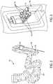
- FIG. 2illustrates an embodiment of a robotic arm and a tool assembly releasably coupled to the robotic arm
- FIG. 3illustrates an embodiment of a tool driver
- FIG. 4illustrates an embodiment of a tool assembly uncoupled from a robotic arm
- FIG. 5illustrates an embodiment of a puck and a proximal end of a shaft extending from the puck
- FIG. 6illustrates an embodiment of the actuation assembly components of a puck
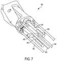
- FIG. 7illustrates a distal end of actuation shafts extending from a wrist located just proximal of an end effector
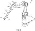
- FIG. 8illustrates an embodiment of a robotic arm and a tool assembly releasably coupled to the robotic arm
- FIG. 9illustrates an embodiment of a tool driver
- FIG. 10illustrates a portion of a puck actuation assembly contained within a puck
- FIG. 11illustrates an embodiment of a puck coupled to a driver with actuators extending from the driver into the puck and engaging driving member
- FIG. 12illustrates the degrees of freedom of movement within a surgical robotic system
- FIG. 13illustrates an embodiment of a computer system
- FIG. 14Aillustrates an embodiment of an end effector
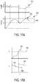
- FIG. 14Billustrates a bend load caused by a force exerted against the end effector of FIG. 14A ;
- FIG. 14Cillustrates a longitudinal load caused by a force exerted against the end effector of FIG. 14A ;
- FIG. 15Aillustrates a top view of an embodiment of an end effector
- FIG. 15Billustrates a perspective view of the end effector of FIG. 15A ;
- FIG. 15Cillustrates a side view of an embodiment of the end effector of FIG. 15A ;
- FIG. 15Dillustrates a cross sectional view of the end effector of FIG. 15A ;
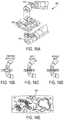
- FIG. 16Aillustrates an embodiment of an end effector
- FIGS. 16B-16Dare schematic views illustrating an example of a sequence of operations of the end effector of FIG. 16A ;
- FIG. 16Eis a schematic view illustrating an example of patterns that can be created by an end effector
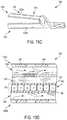
- FIG. 17Aillustrates a cross sectional view of an embodiment of an end effector
- FIG. 17Billustrates a top view of an embodiment of an end effector
- FIG. 18Aillustrates graphs showing power adjustments when treating tissue with one or more forms of energy
- FIG. 18Billustrates graphs showing adjustments of energy types while treating tissue with one or more forms of energy.
- FIG. 19illustrates an embodiment of a process for controlling an application of energy to tissue.
- like-named components of the embodimentsgenerally have similar features, and thus within a particular embodiment each feature of each like-named component is not necessarily fully elaborated upon.
- linear or circular dimensionsare used in the description of the disclosed systems, devices, and methods, such dimensions are not intended to limit the types of shapes that can be used in conjunction with such systems, devices, and methods.
- a person skilled in the artwill recognize that an equivalent to such linear and circular dimensions can easily be determined for any geometric shape. Sizes and shapes of the systems and devices, and the components thereof, can depend at least on the anatomy of the subject in which the systems and devices will be used, the size and shape of components with which the systems and devices will be used, and the methods and procedures in which the systems and devices will be used.
- one or more forms of energycan be used to treat (e.g., cut and cauterize) tissue during surgical procedures.
- Certain surgical instrumentscan be adapted to apply ultrasonic energy and/or radio frequency (RF) energy, which acts to cut the tissue while simultaneously creating a seal in the tissue by denaturing the proteins (e.g., collagen) present within the tissue.
- RFradio frequency
- the amount of energy (e.g., RF and/or ultrasonic) that is applied when treating tissueis critical. Particularly, a sufficient amount of energy must be applied in order to ensure that the tissue is properly cauterized and sealed. But the amount of energy that is applied can vary depending on the speed at which the surgical instrument is moved along or through the tissue. Here, subjective control over the motion of the instrument can introduce irregularities into the treatment process. For example, tissue may be subject to a “cold cut” (e.g., cut without being cauterized) when a fast moving instrument delivers only a small amount of energy along the path of the instrument. Alternately, a slow moving or lingering instrument can apply an excessive amount of energy thereby overheating and damaging the tissue.
- a cold cute.g., cut without being cauterized
- a slow moving or lingering instrumentcan apply an excessive amount of energy thereby overheating and damaging the tissue.
- the robotic systemcan determine an appropriate amount of energy to apply during the treatment of tissue.
- the instrumentcan be configured to sense parameters including, for example, tissue temperature and tension.
- the tension exhibited by the tissuecan indicate a velocity of the instrument's movement through tissue.
- the robotic systemcan adjust an amount of energy applied to the tissue based on the parameters sensed by the instrument. This automatic adjustment of energy based on sensed parameters can eliminate operational errors (e.g., cold cutting, overheating) that stem from a human operator's subjective control over the movement of the surgical instrument.
- the parameter(s)can be sensed via one or more sensors on the tool or end effector that is applying the energy to tissue, or by one or more sensors located remotely from the end effector or tool that is applying the energy, such as an adjacent end effector or surgical tool that may be mounted on an adjacent robotic arm.
- the systems, devices, and methods disclosed hereincan be implemented using a robotic surgical system.
- electronic communication between various components of a robotic surgical systemcan be wired or wireless.
- a person skilled in the artwill also appreciate that all electronic communication in the system can be wired, all electronic communication in the system can be wireless, or some portions of the system can be in wired communication and other portions of the system can be in wireless communication.
- FIG. 1is a perspective view of one embodiment of a surgical robotic system 300 that includes a patient-side portion 310 that is positioned adjacent to a patient 312 , and a user-side portion 311 that is located a distance from the patient, either in the same room and/or in a remote location.
- the patient-side portion 310generally includes one or more robotic arms 320 and one or more tool assemblies 330 that are configured to releasably couple to a robotic arm 320 .
- the user-side portion 311generally includes a vision system 313 for viewing the patient 312 and/or surgical site, and a control system 315 for controlling the movement of the robotic arms 320 and each tool assembly 330 during a surgical procedure.
- the control system 315can have a variety of configurations and it can be located adjacent to the patient, e.g., in the operating room, remote from the patient, e.g., in a separate control room, or it can be distributed at two or more locations.
- a dedicated system control consolecan be located in the operating room, and a separate console can be located in a remote location.
- the control system 315can include components that enable a user to view a surgical site of a patient 312 being operated on by the patient-side portion 310 and/or to control one or more parts of the patient-side portion 310 (e.g., to perform a surgical procedure at the surgical site 312 ).
- control system 315can also include one or more manually-operated input devices, such as a joystick, exoskeletal glove, a powered and gravity-compensated manipulator, or the like. These input devices can control teleoperated motors which, in turn, control the movement of the surgical system, including the robotic arms 320 and tool assemblies 330 .
- manually-operated input devicessuch as a joystick, exoskeletal glove, a powered and gravity-compensated manipulator, or the like.
- These input devicescan control teleoperated motors which, in turn, control the movement of the surgical system, including the robotic arms 320 and tool assemblies 330 .
- the patient-side portioncan also have a variety of configurations. As depicted in FIG. 1 , the patient-side portion 310 can couple to an operating table 314 . However, in some embodiments, the patient-side portion 310 can be mounted to a wall, to the ceiling, to the floor, or to other operating room equipment. Further, while the patient-side portion 310 is shown as including two robotic arms 320 , more or fewer robotic arms 320 may be included. Furthermore, the patient-side portion 310 can include separate robotic arms 320 mounted in various positions, such as relative to the surgical table 314 (as shown in FIG. 1 ). Alternatively, the patient-side portion 310 can include a single assembly that includes one or more robotic arms 320 extending therefrom.
- FIG. 2illustrates one embodiment of a robotic arm 420 and a tool assembly 430 releasably coupled to the robotic arm 420 .
- the robotic arm 420can support and move the associated tool assembly 430 along one or more mechanical degrees of freedom (e.g., all six Cartesian degrees of freedom, five or fewer Cartesian degrees of freedom, etc.).
- the robotic arm 420can include a tool driver 440 at a distal end of the robotic arm 420 , which can assist with controlling features associated with the tool assembly 430 .
- the robotic arm 420can also include an entry guide 432 (e.g., a cannula mount or cannula) that can be a part of or removably coupled to the robotic arm 420 , as shown in FIG. 2 .
- a shaft 436 of the tool assembly 430can be inserted through the entry guide 430 for insertion into a patient.
- a barrier 434can be placed between the actuating portion of the surgical system (e.g., the robotic arm 420 ) and the surgical instruments (e.g., the tool assembly 430 ).
- a sterile componentsuch as an instrument sterile adapter (ISA)
- ISAinstrument sterile adapter
- the placement of an ISA between the tool assembly 430 and the robotic arm 420can ensure a sterile coupling point for the tool assembly 430 and the robotic arm 420 . This permits removal of tool assemblies 430 from the robotic arm 420 to exchange with other tool assemblies 430 during the course of a surgery without compromising the sterile surgical field.
- FIG. 3illustrates the tool driver 440 in more detail.
- the tool driver 440includes one or more motors, e.g., five motors 442 are shown, that control a variety of movements and actions associated with the tool assembly 430 , as will be described in greater detail below.
- each motor 442can couple to and/or interact with an activation feature (e.g., gear) associated with the tool assembly 430 for controlling one or more actions and movements that can be performed by the tool assembly 430 , such as for assisting with performing a surgical operation.
- the motors 442are accessible on the upper surface of the tool driver 440 , and thus the tool assembly is configured to mount on top of the tool driver 440 to couple thereto.
- the tool driver 440also includes a shaft-receiving channel 444 formed in a sidewall thereof for receiving the shaft of the tool assembly 430 .
- the shaftcan extend through on opening in the tool driver 440 , or the two components can mate in various other configurations.
- FIG. 4illustrates the tool assembly 430 uncoupled from the robotic arm 420 .
- the tool assembly 430includes a housing or puck 435 coupled to a proximal end of a shaft 436 and an end effector 438 coupled to a distal end of the shaft 436 .
- the puck 435can include coupling features that assist with releasably coupling the puck 435 to the tool driver 440 of the robotic arm 420 .
- the puck 435can include gears and/or actuators that can be actuated by the one or more motors 442 in the driver 440 , as will be described in greater detail below.
- the gears and/or actuators in the puck 435can control the operation of various features associated with the end effector 438 (e.g., clamping, firing, rotation, articulation, energy delivery, etc.), as well as control the movement of the shaft 436 (e.g., rotation of the shaft).
- various features associated with the end effector 438e.g., clamping, firing, rotation, articulation, energy delivery, etc.
- control the movement of the shaft 436e.g., rotation of the shaft.
- the shaft 436can be fixed to the puck 435 , or it can be releasably coupled to the puck 435 such that the shaft 436 can be interchangeable with other shafts. This can allow a single puck 435 to be adaptable to various shafts 436 having different end effectors 438 .
- the shaft 436can include actuators and connectors that extend along the shaft and assist with controlling the actuation and/or movement of the end effector 438 and/or shaft 436 .
- the shaft 436can also include one or more joints or wrists 437 that allow a part of the shaft 436 or the end effector 438 to articulate relative to the longitudinal axis of the shaft 436 .
- the end effector 438can include any of a variety of surgical tools, such as a stapler, a clip applier, forceps, a needle driver, a cautery device, a cutting tool, a pair of jaws, an imaging device (e.g., an endoscope or ultrasound probe), or a combined device that includes a combination of two or more various tools.
- surgical toolssuch as a stapler, a clip applier, forceps, a needle driver, a cautery device, a cutting tool, a pair of jaws, an imaging device (e.g., an endoscope or ultrasound probe), or a combined device that includes a combination of two or more various tools.
- FIG. 5illustrates an embodiment of a puck 735 and a proximal end of a shaft 736 extending from the puck 735 .
- the puck 735includes a plurality of actuation gears and gear shafts that can be either directly or indirectly controlled by any one of the motors 442 associated with the driver 440 .
- the puck 735is configured to couple to five motors at the locations indicated by reference numbers M 1 , M 2 , M 3 , M 4 , and M 5 .
- puck 735includes first and second articulation gears G 1 , G 2 that are coupled respectively to the first and second motors M 1 , M 2 via a series of one or more additional gears and shafts. Actuation of the first and second motors M 1 , M 2 will rotate the articulation gears G 1 , G 2 , which in turn cause linear movement of an articulation cable in a proximal or distal direction to thereby cause articulation of the end effector 438 in desired left and right directions.
- the puck 735also includes a shaft rotation gear G 3 a that is coupled to the third motor M 3 via a series of one or more additional gears and shafts.
- the third motor M 3will thus rotate the shaft rotation gear G 3 a thereby causing rotation of the shaft 436 of the tool assembly 430 .
- the third motor M 3can also be configured to shift and to couple, via a series of one or more additional gears and shafts, to a head rotation gear G 3 b , which will cause rotation of the end effector 438 relative to the shaft 436 .
- the puck 735further includes a firm close gear G 4 a that is coupled to the fourth motor M 4 via a series of one or more additional gears and shafts. Actuation of the fourth motor M 4 will rotate the firm close gear G 4 a to cause linear translation of a drive screw to firmly close the jaws of the end effector 438 .
- the puck 735further includes a quick close gear G 4 b that can also couple to the fourth motor M 4 via a series of one or more additional gears and shafts.
- a quick close gear G 4 bthat can also couple to the fourth motor M 4 via a series of one or more additional gears and shafts.
- actuation of the fourth motor M 4will rotate the quick close gear G 4 b to cause linear translation of a quick close cable to quickly close the jaws of the end effector 438 .
- the illustrated puck 735includes a firing gear G 5 that is coupled to the fifth motor M 5 via a series of one or more additional gears and shafts. Actuation of the fifth motor M 5 will rotate the firing gear G 5 , thereby driving a lead screw linearly to advance a sled through the end effector 438 , as will be discussed in more detail below.
- FIG. 6illustrates the actuation assembly 870 components of the puck of FIG. 5 .
- each of the gears G 1 -G 5is coupled to an actuation shaft that extends from the actuation assembly 870 and along the shaft 436 of the tool assembly 430 , such as for controlling the movements of the end effector.
- FIG. 7illustrates a distal end of the actuation shafts extending from a wrist 980 located just proximal of the end effector 438 .
- the wrist 980can allow for fine movements and angulation of the end effector 438 relative to the proximal end of the shaft 436 .
- FIG. 7illustrates a distal end of the actuation shafts extending from a wrist 980 located just proximal of the end effector 438 .
- the wrist 980can allow for fine movements and angulation of the end effector 438 relative to the proximal end of the shaft 436 .
- the wrist 980includes four articulation cables 982 that are spaced around a perimeter of the wrist 980 .
- the articulation cables 982When actuated (e.g., pushed, pulled, rotated), the articulation cables 982 will cause articulation of the end effector 438 (e.g., movement up, down, left, right, and combinations thereof) relative to the proximal end of the shaft 436 .
- the articulation cables 982are connected to the articulation couplers 839 , shown in FIG. 6 , that are driven proximally and distally when the articulation gears G 1 , G 2 are actuated by the first and second motors M 1 , M 2 .
- the wrist 980also includes an upper rotary driver 984 that when actuated can cause the pair of jaws of the end effector 438 to firmly close.
- the upper rotary driver 984is coupled to the firm close gear G 4 a shown in FIG. 6 such that rotation of the firm close gear G 4 a by the motor M 4 causes rotation of the rotary driver 984 .
- the wrist 980can also include a lower rotary driver 986 that when actuated can cause movement of a sled located at the end effector 438 .
- the lower rotary driver 986is coupled to the firing gear G 5 shown in FIG. 6 and it likewise rotates in response to rotation of the firing gear G 5 .
- the illustrated wrist 980further includes a linear pull cable 988 that is coupled to the quick close gear G 4 b shown in FIG. 6 and that moves linearly in a proximal direction to cause rapid close of the pair of jaws.
- FIG. 8illustrates another embodiment of a robotic arm 1120 and a tool assembly 1130 releasably coupled to the robotic arm 1120 .
- the robotic arm 1120can support and move the associated tool assembly 1130 along one or more mechanical degrees of freedom (e.g., all six Cartesian degrees of freedom, five or fewer Cartesian degrees of freedom, etc.).
- the robotic arm 1120can include a tool driver 1140 at a distal end of the robotic arm 1120 , which can assist with controlling features associated with the tool assembly 1130 .
- the robotic arm 1120can also include a movable tool guide 1132 that can retract and extend relative to the driver 1140 .
- a shaft of the tool assembly 1130can extend parallel to a threaded shaft of the movable tool guide 1132 and can extend through a distal end feature 1133 (e.g., a ring) of the movable tool guide 1130 and into a patient.
- a barrier(not shown) can be placed between the actuating portion of the surgical system (e.g., the robotic arm 1120 ) and the surgical instruments (e.g., the tool assembly 1130 ) in the sterile surgical field.
- a sterile componentsuch as an instrument sterile adapter (ISA)
- ISAinstrument sterile adapter
- the placement of an ISA between the tool assembly 1130 and the robotic arm 1120can ensure a sterile coupling point for the tool assembly 1130 and the robotic arm 1120 . This permits removal of tool assemblies 1130 from the robotic arm 1120 to exchange with other tool assemblies 1130 during the course of a surgery without compromising the sterile surgical field.
- FIG. 9illustrates the tool driver 1140 in more detail.
- the tool driver 1140includes one or more motors, e.g., seven motors M 1 -M 7 are shown, that control a variety of movements and actions associated with the tool assembly 1130 , as will be described in greater detail below.
- the driver 1140can also include one or more lead screws (e.g., three lead screws L 1 , L 2 , and L 3 are shown) that can be individually rotated by a motor and, as a result of the rotation of the lead screw, cause linear and/or rotational movement of at least one actuator (e.g., see, for example, actuators A 1 and A 2 shown in FIG. 9 ).
- Movement of each actuatorcontrols the movement of driving members (e.g., gears, cables) located in the tool assembly 1130 for controlling one or more actions and movements that can be performed by the tooling assembly 1130 , such as for assisting with performing a surgical operation.
- the actuatorsextend from a top end of the driver 1140 for coupling to the driving members of the tool assembly 1130 mounted on top of the tool driver 1140 .
- the tool assembly 1130can be loaded from a top side of the driver 1140 with the shaft of the tool assembly 1130 being positioned in a shaft-receiving channel 1144 formed along the side of the driver 1140 .
- the shaft-receiving channel 1144allows the shaft, which extends along a central axis of the tool assembly 1130 , to extend along a central axis of the driver 1140 when the tool assembly 1130 is coupled to the driver 1140 .
- the shaftcan extend through on opening in the tool driver 1140 , or the two components can mate in various other configurations.
- the tool assembly 1130includes a housing or puck 1135 coupled to a proximal end of a shaft 1136 and an end effector 1138 coupled to a distal end of the shaft 1136 .
- the puck 1135can include coupling features that assist with releasably coupling the puck 1135 to the tool driver 1140 of the robotic arm 1120 .
- the puck 1135can include driving members (e.g., gears, cables, and/or drivers) that can be directly or indirectly actuated by the one or more motors M 1 -M 5 , as will be described in greater detail below.
- the driving members in the puck 1135can control the operation of various features associated with the end effector 1138 (e.g., clamping, firing, rotation, articulation, etc.), as well as control the movement of the shaft 1136 (e.g., rotation and/or articulation of the shaft).
- the shaft 1136can be releasably coupled to the puck 1135 such that the shaft 1136 can be interchangeable with other shafts. This can allow a single puck 1135 to be adaptable to various shafts 1136 having different end effectors 1138 .
- the shaft 1136can include actuators and connectors that extend along the shaft and assist with controlling the actuation and/or movement of the end effector 1138 and/or shaft 1136 .
- the shaft 1136can also include one or more joints or wrists 1137 that allow a part of the shaft 1136 or the end effector 1138 to rotate and/or articulate relative to the longitudinal axis of the shaft 1136 . This can allow for fine movements and various angulation of the end effector 1138 relative to the longitudinal axis of the shaft 1136 .
- the end effector 1138can include any of a variety of surgical tools, such as a stapler, a clip applier, forceps, a needle driver, a cautery device, a cutting tool, a pair of jaws, an imaging device (e.g., an endoscope or ultrasound probe), or a combined device that includes a combination of two or more various tools.
- surgical toolssuch as a stapler, a clip applier, forceps, a needle driver, a cautery device, a cutting tool, a pair of jaws, an imaging device (e.g., an endoscope or ultrasound probe), or a combined device that includes a combination of two or more various tools.
- FIG. 10illustrates a part of a puck actuation assembly contained within the puck 1135 .
- the puck 1135includes at least one driving member (e.g., four driving members D 1 , D 2 , D 3 , and D 4 are shown) that can each become engaged with an actuator of the driver 1140 such that actuation of an actuator causes actuation of a driving member thereby controlling the operation of various features associated with the shaft 1136 and/or end effector 1138 .
- Each driving member D 1 -D 4can be coupled to a proximal end of a shaft or cable (e.g., four cables C 1 , C 2 , C 3 , and C 4 are shown). Each cable can extend from a driving member and couple to a feature associated with either the shaft 1136 or the end effector 1138 thereby controlling a function of such feature.
- FIG. 11illustrates the puck 1135 coupled to the driver 1140 with the actuators extending from the driver 1140 into the puck 1135 and engaging the driving members.
- motor M 1can cause lead screw L 1 to rotate thereby causing actuator A 1 , which is threadably coupled to lead screw L 1 , to linearly advance in the proximal direction (towards and into the puck 1135 ).
- Actuator A 1can include an extension threadably coupled to the lead screw L 1 .
- the extensioncan be coupled to or integrated with a partial cylindrical shaft that extends along the longitudinal axis of the puck 1135 and the driver 1140 .
- the partial cylindrical shaft of the actuator A 1can engage with driving member D 1 such that when the actuator A 1 is linearly advanced, the driving member D 1 is caused to linearly advance in the same direction.
- Driving member D 1can be coupled to cable C 1 such that when driving member D 1 is advanced in the proximal direction, cable C 1 is pulled in the proximal direction.
- Cable C 1extends along the shaft of the tool assembly 1130 and is operatively coupled to a part of the end effector 1138 thereby controlling a function of the end effector 1138 (e.g., opening and closing of jaws, deployment of a staple, etc.) when the cable is C 1 translated in either the proximal or distal direction.
- four motorscan each individually control movement of a respective lead screw (e.g., L 1 -L 4 ) thereby individually linearly translating a respective actuator (e.g., A 1 -A 4 ) coupled thereto.
- a respective lead screwe.g., L 1 -L 4
- a respective actuatore.g., A 1 -A 4
- the actuatorsare described as being linearly translated, the actuators can be linearly translated and/or rotationally moved as a result of actuation of a respective motor.
- Additional motorse.g., motors M 5 and M 6
- motor M 5can cause a first driver shaft 1141 to rotate, which is operatively coupled to a first puck shaft 1147 having a first puck gear 1143 coupled to a distal end of the first puck shaft 1147 .
- Rotation of the first driver shaft 1141thereby causes the first puck shaft 1147 and first puck gear 1143 to rotate.
- the first puck gear 1143is engaged with a first shaft rotation gear 1148 that is caused to rotate as a result of the first puck gear 1143 rotating.
- the first shaft rotation gear 1148is operatively coupled to the shaft 1136 of the tool assembly 1130 and can thereby cause rotation of the shaft 1136 and/or end effector 1138 .
- Motor M 6can cause a second driver shaft to rotate, which is operatively coupled to a second puck gear 1153 .
- the second puck gear 1153is engaged with a second shaft rotation gear 1154 that is caused to rotate as a result of the second puck gear 1153 rotating.
- the second shaft rotation gear 1154is also operatively coupled to the shaft 1136 and, upon rotation, provides additional torque through the shaft 1136 and for various features associated with the end effector 1138 .
- Actuation of motor M 7can cause shaft gears 1161 to rotate, thereby causing the threaded shaft of the movable tool guide 1132 to linearly translate.
- the degrees of freedom of a systemare the number of independent variables that uniquely identify its pose or configuration.
- the set of Cartesian degrees of freedomis usually represented by the three translational or position variables, e.g., surge, heave, and sway, and by the three rotational or orientation variables, e.g., Euler angles or roll, pitch, and yaw, that describe the position and orientation of a component of a surgical system with respect to a given reference Cartesian frame.
- the three translational or position variablese.g., surge, heave, and sway
- the three rotational or orientation variablese.g., Euler angles or roll, pitch, and yaw
- the term “surge”refers to forward and backward movement
- the term “heave”refers to movement up and down
- the term “sway”refers to movement left and right.
- the rotational terms“roll” refers to tilting side to side
- “pitch”refers to tilting forward and backward
- “yaw”refers to turning left and right.
- each of the translation termsrefers to movement along one of the three axes in a Cartesian frame
- each of the rotational termsrefers to rotation about one of the three axes in a Cartesian frame.
- the number of degrees of freedomis at most six, a condition in which all the translational and orientation variables are independently controlled, the number of joint degrees of freedom is generally the result of design choices that involve considerations of the complexity of the mechanism and the task specifications.
- the number of independently controlled jointsis equal to the degree of mobility for an end effector.
- the end effectorwill have an equal number of degrees of freedom in Cartesian space that will correspond to a combination of translational and rotational motions. Accordingly, the number of degrees of freedom can be more than, equal to, or less than six.
- forwardrefers to an end of the surgical system that is closest to the distal end of the input tool, and when in use in a surgical procedure, to the end disposed within a patient's body.
- rearwardrefers to an end of the surgical system farthest from the distal end of the input tool, and when in use, generally to the end farther from the patient.
- spatially relative termse.g., “superior,” “inferior,” “beneath,” “below,” “lower,” “above,” “upper,” “rearward,” “forward,” etc.
- These spatially relative termsare intended to encompass different positions and orientations of the device in use or operation in addition to the position and orientation shown in the figures. For example, if the device in the figures is turned over, elements described as “inferior to” or “below” other elements or features would then be “superior to” or “above” the other elements or features.
- An end effectoris the part of a surgical instrument or assembly that performs a specific surgical function, e.g., forceps/graspers, needle drivers, scissors, electrocautery hooks, staplers, clip appliers/removers, suction tools, irrigation tools, etc. Any end effector can be utilized with the surgical systems described herein. Further, in exemplary embodiments, an end effector can be configured to be manipulated by a user input tool.
- the input toolcan be any tool that allows successful manipulation of the end effector, whether it be a tool similar in shape and style to the end effector, such as an input tool of scissors similar to end effector scissors, or a tool that is different in shape and style to the end effector, such as an input tool of a glove dissimilar to end effector graspers, and such as an input tool of a joystick dissimilar to end effector graspers.
- the input toolcan be a larger scaled version of the end effector to facilitate ease of use.
- Such a larger scale input toolcan have finger loops or grips of a size suitable for a user to hold.
- the end effector and the input toolcan have any relative size.
- a slave tool, e.g., a surgical instrument, of the surgical systemcan be positioned inside a patient's body cavity through an access point in a tissue surface for minimally invasive surgical procedures.
- cannulassuch as trocars are used to provide a pathway through a tissue surface and/or to prevent a surgical instrument or guide tube from rubbing on patient tissue.
- Cannulascan be used for both incisions and natural orifices.
- Some surgical proceduresrequire insufflation, and the cannula can include one or more seals to prevent excess insufflation gas leakage past the instrument or guide tube.
- the cannulacan have a housing coupled thereto with two or more sealed ports for receiving various types of instruments besides the slave assembly.
- any of the surgical system components disclosed hereincan have a functional seal disposed thereon, therein, and/or therearound to prevent and/or reduce insufflation leakage while any portion of the surgical system is disposed through a surgical access port, such as a cannula.
- the surgical systemscan also be used in open surgical procedures.
- a surgical access pointis a point at which the slave tool enters a body cavity through a tissue surface, whether through a cannula in a minimally invasive procedure or through an incision in an open procedure.
- the systems, devices, and methods disclosed hereincan be implemented using one or more computer systems, which may also be referred to herein as digital data processing systems and programmable systems.
- One or more aspects or features of the subject matter described hereincan be realized in digital electronic circuitry, integrated circuitry, specially designed application specific integrated circuits (ASICs), field programmable gate arrays (FPGAs) computer hardware, firmware, software, and/or combinations thereof.
- ASICsapplication specific integrated circuits
- FPGAsfield programmable gate arrays
- These various aspects or featurescan include implementation in one or more computer programs that are executable and/or interpretable on a programmable system including at least one programmable processor, which can be special or general purpose, coupled to receive data and instructions from, and to transmit data and instructions to, a storage system, at least one input device, and at least one output device.
- the programmable system or computer systemmay include clients and servers.
- a client and serverare generally remote from each other and typically interact through a communication network. The relationship of client and server arises by virtue of computer programs running on the respective computers and having a client-server relationship to each other.
- the computer programswhich can also be referred to as programs, software, software applications, applications, components, or code, include machine instructions for a programmable processor, and can be implemented in a high-level procedural language, an object-oriented programming language, a functional programming language, a logical programming language, and/or in assembly/machine language.
- machine-readable mediumrefers to any computer program product, apparatus and/or device, such as for example magnetic discs, optical disks, memory, and Programmable Logic Devices (PLDs), used to provide machine instructions and/or data to a programmable processor, including a machine-readable medium that receives machine instructions as a machine-readable signal.
- machine-readable signalrefers to any signal used to provide machine instructions and/or data to a programmable processor.
- the machine-readable mediumcan store such machine instructions non-transitorily, such as for example as would a non-transient solid-state memory or a magnetic hard drive or any equivalent storage medium.
- the machine-readable mediumcan alternatively or additionally store such machine instructions in a transient manner, such as for example as would a processor cache or other random access memory associated with one or more physical processor cores.
- one or more aspects or features of the subject matter described hereincan be implemented on a computer having a display device, such as for example a cathode ray tube (CRT) or a liquid crystal display (LCD) or a light emitting diode (LED) monitor for displaying information to the user and a keyboard and a pointing device, e.g., a mouse, a trackball, etc., by which the user may provide input to the computer.
- a display devicesuch as for example a cathode ray tube (CRT) or a liquid crystal display (LCD) or a light emitting diode (LED) monitor for displaying information to the user and a keyboard and a pointing device, e.g., a mouse, a trackball, etc.
- CTRcathode ray tube
- LCDliquid crystal display
- LEDlight emitting diode
- a keyboard and a pointing devicee.g., a mouse, a trackball, etc.
- Other kinds of devices
- feedback provided to the usercan be any form of sensory feedback, such as for example visual feedback, auditory feedback, or tactile feedback; and input from the user may be received in any form, including, but not limited to, acoustic, speech, or tactile input.
- Other possible input devicesinclude, but are not limited to, touch screens or other touch-sensitive devices such as single or multi-point resistive or capacitive trackpads, voice recognition hardware and software, optical scanners, optical pointers, digital image capture devices and associated interpretation software, and the like.
- FIG. 13illustrates an embodiment of a computer system 100 .
- the computer system 100includes one or more processors 102 which can control the operation of the computer system 100 .
- processorsare also referred to herein as “controllers.”
- the processor(s) 102can include any type of microprocessor or central processing unit (CPU), including programmable general-purpose or special-purpose microprocessors and/or any one of a variety of proprietary or commercially available single or multi-processor systems.
- the computer system 100can also include one or more memories 104 , which can provide temporary storage for code to be executed by the processor(s) 102 or for data acquired from one or more users, storage devices, and/or databases.
- the memory 104can include read-only memory (ROM), flash memory, one or more varieties of random access memory (RAM) (e.g., static RAM (SRAM), dynamic RAM (DRAM), or synchronous DRAM (SDRAM)), and/or a combination of memory technologies.
- ROMread-only memory
- flash memoryone or more varieties of random access memory (RAM) (e.g., static RAM (SRAM), dynamic RAM (DRAM), or synchronous DRAM (SDRAM)), and/or a combination of memory technologies.
- RAMrandom access memory
- SRAMstatic RAM
- DRAMdynamic RAM
- SDRAMsynchronous DRAM
- the various elements of the computer system 100can be coupled to a bus system 112 .
- the illustrated bus system 112is an abstraction that represents any one or more separate physical busses, communication lines/interfaces, and/or multi-drop or point-to-point connections, connected by appropriate bridges, adapters, and/or controllers.
- the computer system 100can also include one or more network interface(s) 106 , one or more input/output (JO) interface(s) 108 , and one or more storage device(s) 110 .
- JOinput/output
- the network interface(s) 106can enable the computer system 100 to communicate with remote devices, e.g., other computer systems, over a network, and can be, for non-limiting example, remote desktop connection interfaces, Ethernet adapters, and/or other local area network (LAN) adapters.
- the IO interface(s) 108can include one or more interface components to connect the computer system 100 with other electronic equipment.
- the IO interface(s) 108can include high speed data ports, such as universal serial bus (USB) ports, 1394 ports, Wi-Fi, Bluetooth, etc.
- the computer system 100can be accessible to a human user, and thus the IO interface(s) 108 can include displays, speakers, keyboards, pointing devices, and/or various other video, audio, or alphanumeric interfaces.
- the storage device(s) 110can include any conventional medium for storing data in a non-volatile and/or non-transient manner. The storage device(s) 110 can thus hold data and/or instructions in a persistent state, i.e., the value(s) are retained despite interruption of power to the computer system 100 .
- the storage device(s) 110can include one or more hard disk drives, flash drives, USB drives, optical drives, various media cards, diskettes, compact discs, and/or any combination thereof and can be directly connected to the computer system 100 or remotely connected thereto, such as over a network.
- the storage device(s)can include a tangible or non-transitory computer readable medium configured to store data, e.g., a hard disk drive, a flash drive, a USB drive, an optical drive, a media card, a diskette, a compact disc, etc.
- FIG. 13can be some or all of the elements of a single physical machine. In addition, not all of the illustrated elements need to be located on or in the same physical machine.
- Exemplary computer systemsinclude conventional desktop computers, workstations, minicomputers, laptop computers, tablet computers, personal digital assistants (PDAs), mobile phones, and the like.
- PDAspersonal digital assistants
- the computer system 100can include a web browser for retrieving web pages or other markup language streams, presenting those pages and/or streams (visually, aurally, or otherwise), executing scripts, controls and other code on those pages/streams, accepting user input with respect to those pages/streams (e.g., for purposes of completing input fields), issuing HyperText Transfer Protocol (HTTP) requests with respect to those pages/streams or otherwise (e.g., for submitting to a server information from the completed input fields), and so forth.
- the web pages or other markup languagecan be in HyperText Markup Language (HTML) or other conventional forms, including embedded Extensible Markup Language (XML), scripts, controls, and so forth.
- the computer system 100can also include a web server for generating and/or delivering the web pages to client computer systems.
- the computer system 100can be provided as a single unit, e.g., as a single server, as a single tower, contained within a single housing, etc.
- the single unitcan be modular such that various aspects thereof can be swapped in and out as needed for, e.g., upgrade, replacement, maintenance, etc., without interrupting functionality of any other aspects of the system.
- the single unitcan thus also be scalable with the ability to be added to as additional modules and/or additional functionality of existing modules are desired and/or improved upon.
- a computer systemcan also include any of a variety of other software and/or hardware components, including by way of non-limiting example, operating systems and database management systems. Although an exemplary computer system is depicted and described herein, it will be appreciated that this is for sake of generality and convenience. In other embodiments, the computer system may differ in architecture and operation from that shown and described here.
- a robotic surgical systemcan include an electromechanical tool assembly (e.g., tool assembly 330 in FIG. 1 or tool assembly 430 in FIGS. 2-4 ) including a surgical instrument adapted to apply energy, such as ultrasonic and/or radiofrequency (RF) energy, to tissue held by the surgical instrument.
- the electromechanical toolis configured to be mounted on an electromechanical arm (e.g., robotic arm 320 in FIG. 1 or robotic arm 420 in FIG. 2 ) and it is configured to move with or relative to the electromechanical arm.
- the robotic surgical systemfurther includes a controller operatively coupled to the electromechanical arm and the electromechanical tool and configured to control operation of these components.
- the surgical instrumentcan be an end effector or other type of an instrument that can transmit one or more forms of energy (e.g., ultrasonic and/or RF) through tissue to cut and cauterize and seal the tissue. After the seal in tissue is created, application of energy to the tissue is discontinued and tissue is disengaged from the end effector. As discussed above, the proper cutting and sealing of tissue require delivery of an appropriate amount of energy to the tissue. In a typical, manual surgical procedure, a surgeon exercises subjective control over the movement of the surgical instrument, thereby affecting the amount of energy that is applied to the tissue.
- energye.g., ultrasonic and/or RF
- Failure to deliver a proper amount of energy by moving the surgical instrument at an improper speedcan lead to insufficient cutting or sealing (e.g., cold cut), or to unintended tissue damage if too much energy is applied to the tissue.
- the robotic surgical system described hereincan automatically control a level and/or form of energy that is applied to tissue during the treatment of tissue.
- the controller(and/or other suitable component(s) of the robotic surgical system) can be configured to receive, during an application of energy (e.g., ultrasonic and/or RF) to the tissue, a plurality of measurements indicative of a speed at which the surgical instrument is moving across or through the tissue.
- the parameters that indicate the speed at which the surgical instrument is being moved across or through tissueinclude tension that is being exerted against the surgical instrument by the tissue.
- a high level of tensiongenerally indicates that the surgical instrument is being moved at a high speed.
- a high level of tensioncan also indicate certain tissue characteristics including, for example, that the tissue being treated is rough, stiff, and/or thick. In either case, a higher power may be required in order to ensure a proper cut and seal of the tissue.
- the controllercan determine a speed at which the surgical instrument is being moved across or through tissue, and adjust a power that is being applied to the tissue accordingly. Moreover, the controller can further detect when a speed of movement exceeds a certain threshold thereby requiring introduction of an additional form of energy in order to proper cut and cauterize the tissue.
- the robotic surgical systemcan also monitor a temperature of the tissue in order to detect when to adjust the power being applied to the tissue in order to avoid applying an excessive amount of energy and damaging the tissue through overheating.
- the robotic surgical systemcan be configured to control and adjust the level and/or forms of energy in any suitable way.
- the surgical systemcan increase (or reduce) the power being applied and/or turn on an additional form of energy.
- the surgical procedure as described hereinmay not be dependent on a surgeon's subjective control over the movement of the surgical instrument across or through tissue at a treatment site.
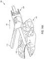
- FIGS. 14A-14Cillustrate an embodiment of an end effector 1400 of a robotic surgical system in accordance with the disclosed techniques.
- the end effector 1400is configured to cut and seal tissue by applying one or more forms of energy (e.g., ultrasonic and/or RF) thereto.
- the end effector 1400can be positioned at a distal end 1412 of an instrument shaft of an electromechanical tool assembly (not shown), such as, for example, the tool assembly 330 ( FIG. 1 ) or 430 ( FIGS. 2-4 ).
- the tool assemblycan be releasably mounted on an electromechanical robotic arm such as, for example, the robotic arm 320 ( FIG. 1 ) or 420 ( FIGS. 2 and 3 ).
- the end effector 1400can be, for example, the end effector 438 ( FIG. 4 ), or any other type of a surgical instrument configured to apply ultrasonic energy or other form of energy to tissue to cut and coagulate it.
- the tool assemblyis configured to move relative to the electromechanical arm.
- the end effector 1400includes an upper jaw or a clamp member 1410 and a lower jaw or blade 1420 that are configured to clamp tissue therebetween or contact tissue in other ways.
- the end effectorcan also be moved over tissue with an outer surface of the blade 1420 positioned in contact with the tissue.
- the end effectorcan be advanced, dragged, or otherwise moved along the tissue to create a cut therethrough or other feature.
- the end effectoralso includes a strain gauge 1430 discussed in more detail below. Other components of the surgical system are not shown in FIGS. 14A-14C for the sake of simplicity.
- the clamp member 1410 and the blade 1420can have a variety of different configurations.
- the clamp member 1410can have a tissue-facing surface configured (e.g., in shape and/or size) to grasp the tissue 1440 (or another type of tissue) between the clamp member 1410 and the blade 1420 .
- the tissue-facing surface of the clamp member 1410can have one or more surface features adapted to facilitate the grasping and securing of the tissue 1440 (or another type of tissue) between the clamp member 1410 and the blade 1420 .
- the features formed on the tissue-facing surfacecan form one or more patterns or combination of patterns.
- the blade 1420can be configured to treat (e.g., cut and/or cauterize) the tissue 1440 when one or more forms of energy are applied thereto.
- the end effector 1400can include a transmission element or waveguide (not shown separately) that is configured to transmit ultrasonic from an energy source to the blade 1420 .
- the blade 1420can be integral with the waveguide so as to form a single unit, or they can be separate elements connected to one another in a suitable way.
- one or more electrodescan be present on upper and lower jaws 1410 , 1420 (and any knife blade that may be present) so as to communicate energy between the electrodes and a suitable electrosurgical generator.
- the blade 1420can be configured to transmit one or more forms of energy to tissue in order to treat the tissue in a controlled manner.
- the described robotic surgical systemcan include an ultrasonic transducer coupled to an ultrasonic generator via a suitable transmission medium.
- the ultrasonic transducercan be coupled to the waveguide to transmit ultrasound signals thereto.
- the described robotic surgical systemcan have other components configured to deliver ultrasound energy to the end effector 1400 .
- the robotic surgical systemcan additionally include an RF generator coupled to a suitable source of RF energy. Regardless of the type, number, and configuration of such components, they can be controlled via a controller system, e.g., the control system 315 in FIG. 1 , or any other controller(s).
- the end effector 1400can be configured to apply one or both ultrasound and RF energy to tissue.
- the end effectorcan have an isolated electrode on the lower jaw that provides energy to tissue and that is configured to provide a return path for either type of energy back to a generator.
- the end effectorincludes an ultrasonic blade
- the movement of the end effector across tissuecan be referred as “back cutting.”
- a technique of “dragging” across tissuecan be performed using monopolar blades and exposed ultrasonic blades.
- an RF devicecan be used in the described manner a bipolar mode (i.e., the device includes two electrical poles or contacts).
- the RF devicecan have a tip configured to be used for both monopolar and bipolar cutting functions.
- a non-limiting example of such deviceis Enseal PowerTip (SurgRx, Inc.).
- the end effector 1400can be adapted to sense one or more parameters including, for example, a force F exerted against the end effector 1400 .
- FIG. 14Aillustrates by way of example a position of the end effector 1400 when it is moved (e.g., dragged) along a tissue 1440 in a direction of an arrow 1401 .
- the end effector 1400is moved in the direction 1401 as the tissue 1440 is being cut such that the cut is created.
- the strain gauge 1430can be configured to measure the force F exerted against the end effector 1400 (e.g., the blade 1420 ) by the tissue 1440 .
- the strain gauge 1430is subjected to a bend load that corresponds to the force F exerted against the end effector 1400 (e.g., the blade 1420 ).
- the tissue 1440is in the form of mesentery tissue.
- the tissue 1440can be any other type of tissue without departing from the scope of the present disclosure.
- FIG. 14Billustrates an example in which the end effector 1400 is moved (e.g., advanced) in a direction shown by an arrow 1402 to treat a vessel 1450 disposed over the blade 1420 .
- the vessel 1450causes a deformation strain or load in the form of a force F exerted against a distal end of the blade 1420 .
- the gauge 1430measures this strain or load.
- the strain gauge 1430can measure a longitudinal load that corresponds to the force F exerted against the end effector 1400 (e.g., against the blade 1420 ).
- FIGS. 14B and 14Cillustrates an example in which the end effector 1400 is moved (e.g., dragged) in a direction shown by an arrow 1403 along the vessel 1450 .
- the end effector 1400experiences a longitudinal load caused by the force F exerted against the blade 1420 by the vessel 1450 .
- the vessel 1450is shown in FIGS. 14B and 14C by way of example only.
- the force Fcan correspond to a tension across tissue, such as the tissue 1440 ( FIG. 14A ) or the vessel 1450 ( FIGS. 14B and 14C ).
- tissuesuch as the tissue 1440 ( FIG. 14A ) or the vessel 1450 ( FIGS. 14B and 14C ).
- the tissuewhen the tissue is rough, stiff, and/or thick, the tissue can exhibit high tension and therefore present greater resistance against the movement of the blade 1420 through the tissue.
- the magnitude of the force Fcan be indicative of one or more characteristics of the tissue including, for example, the roughness, stiffness, and/or thickness of the tissue.
- the force Fcan also correspond to a velocity of the end effector 1400 (e.g., the blade 1420 ) through the tissue.
- the blade 1420can encounter greater resistance from the tissue when the end effector 1400 is being moved (e.g., advanced or dragged) quickly (e.g., by the robotic arm 200 ) through the tissue.
- the magnitude of the force Fcan also be indicative of a speed of the movement of the end effector 1400 through the tissue.
- the end effector 1400can be adapted to apply, to the tissue 1440 , RF energy, ultrasonic energy, and/or a combination of both.
- the level and/or forms of energy (e.g., RF and/or ultrasonic) applied by the end effector 1400can be controlled by the control system 115 based on the parameters sensed by the end effector 1400 .
- the level and/or forms of energy applied by the end effector 1400can be adjusted based on the force F exerted against the end effector 1400 (e.g., the blade 1420 ) by the tissue 1440 .
- control system 115can increase the power and/or combine the different types of energies (e.g., combination ultrasonic and RF) applied by the end effector 1400 when the force F indicates that the tissue 1440 is rough, stiff, and/or thick. Alternately or additionally, the control system 115 can increase the power and/or combine the different types of energies applied by the end effector 1400 when the force F indicates that the end effector 1400 is being moved (e.g., advanced or dragged) quickly (e.g., by the robotic arm 200 ) through the tissue 1440 .
- energiese.g., combination ultrasonic and RF
- FIGS. 15A-15Dillustrate an embodiment of an end effector 1500 of a robotic system in accordance with the disclosed techniques.
- the end effector 1500is adapted to cut and seal tissue by applying one or more forms of energy (e.g., RF) thereto.
- the end effector 1500can be positioned at a distal end 1512 of an instrument shaft of an electromechanical tool assembly (not shown), such as, for example, the tool assembly 330 ( FIG. 1 ) or 430 ( FIGS. 2-4 ).
- the tool assemblycan be releasably mounted on an electromechanical robotic arm such as, for example, the robotic arm 320 ( FIG. 1 ) or 420 ( FIGS. 2 and 3 ).
- the end effector 1500can be, for example, the end effector 438 ( FIG. 4 ), or any other type of a surgical instrument configured to apply one or more forms of energy to tissue to cut and coagulate it.
- the tool assemblyis configured to move relative to the electromechanical arm.
- FIG. 15Aillustrates a top view of the end effector 1500 .
- the end effector 1500can include an RF device 1510 adapted to provide RF energy.
- the end effector 1500can also be configured to deliver ultrasound energy to tissue, in which case it includes components required to generate and deliver to the ultrasound energy to tissue.
- the end effector 1500can further include a grasper 1520 , which can include an upper grasper member 1520 A and a lower grasper member 1520 B.
- the end effector 1500can apply RF energy (e.g., from the RF device 1510 ) to a tissue 1530 while the tissue 1530 is secured by the grasper 1520 (e.g., between the upper grasper member 1520 A and the lower grasper member 1520 B).
- the tissue 1530can be any type of tissue (e.g., blood vessel, organ) without departing from the scope of the present disclosure.
- the grasper 1520can have a variety of configurations.
- the upper grasper member 1520 A and/or the lower grasper member 1520 Bcan have a tissue-facing surface configured (e.g., in shape and/or size) to grasp and secure the tissue 1530 between the upper grasper member 1520 A and the lower grasper member 1520 B.
- the tissue-facing surface of the upper grasper member 1520 A and/or the lower grasper member 1520 Bcan have one or more surface features adapted to facilitate the grasping and securing of the tissue 1440 . These features can form one or more patterns or combination of patterns.
- FIG. 15Billustrates a perspective view of the end effector 1500 .
- the end effector 1500can further include a cooling element 1540 and cooling tubes 1545 .
- the cooling element 1540can be disposed on the lower grasper member 1520 B of the grasper 1520 .
- the cooling element 1540can be a Peltier cooler adapted to provide thermoelectric cooling to the tissue 1530 while the tissue 1530 is treated with RF energy from the RF device 1510 . It should be appreciated, however, that any type of cooling element can be used as the described techniques are not limited in this respect.
- FIG. 15Cillustrates schematically a side view of the end effector 1500 .
- the end effector 1500can further include a plurality of sensors including, for example, a first sensor 1550 and a second sensor 1555 .
- the first sensor 1550can be positioned at a distal end of the upper grasper member 1520 A while the second sensor 1550 can be positioned at a proximal end of the upper grasper member 1520 B.
- the first sensor 1550 and the second sensor 1555can be temperature sensors adapted to measure a temperature of the tissue 1530 while the tissue 1530 is treated with RF energy from the RF device 1510 .
- two sensors 1550 , 1555are shown by way of example only and that the end effector 1500 can include any suitable number of sensors, without departing from the scope of the present disclosure.
- the end effectorcan include other type(s) of sensors.
- the end effector 1500can be adapted to apply RF energy (e.g., from the RF device 1510 ) to the tissue 1530 .
- the rate of power provided by the RF device 1510 and applied by the end effector 1500can be controlled by the control system 115 based on the parameters sensed by the end effector 1500 including, for example, the temperature at the tissue 1530 .
- the control system 115can decrease the rate of the RF energy when the temperature at the tissue 1530 is high.
- the control system 115can increase the rate of RF energy when the temperature at the tissue 1530 is low.
- control system 115can be configured to adjust the power by increasing the power when the temperature of the tissue is below a first threshold value and decreasing the power when the temperature of the tissue is above a second threshold value.
- the first and second threshold valuescan be selected based on a number of parameters, such as a type of tissue, type of surgery and/or any other suitable factors. Controlling the rate of RF energy applied to the tissue 1530 based on the temperature at the tissue 1530 can ensure that an adequate amount of RF energy is applied to the tissue 1530 while preventing overheating and damage to the tissue 1530 .
- FIG. 15Dillustrates a cross sectional view of the end effector 1500 .
- the tissue 1530can be secured between the grasper 1520 (e.g., the upper jaw 1520 A and the lower jaw 1520 B) in order to be treated with RF energy from the RF device 1510 .
- the upper jaw 1520 Acan include a first air space 1560 while the lower jaw 1520 B can include a second air space 1565 .
- the first and second air spaces 1560 , 1565(which are referred to as “first” and “second” for description purposes only) can be adapted to provide insulation.
- the cooling element 1540can be adapted to maintain a temperature of the tissue 1530 while the tissue 1530 is treated with RF energy (e.g., from the RF device 1510 ).
- the cooling element 1540can include a hot plate 1542 and a cold plate 1546 .
- the cooling element 1540can further include an interconnect 1544 (e.g., a layer of n-type and p-type semiconductors) disposed between the hot plate 1542 and the cold plate 1546 .
- the cold plate 1546can absorb at least a portion of the heat applied to the tissue 1530 (e.g., by the RF device 1510 ) and transfer the heat to the hot plate 1542 via the interconnect 1544 . This transfer of heat allows the cold plate 1546 to remain cool and to continue cooling the tissue 1530 while the tissue 1530 is treated with RF energy.
- FIG. 16Aillustrates another example of a portion of an end effector 1600 of a robotic surgical system in accordance with the disclosed techniques. Only a distal end of the end effector 1600 is shown, and other components of the surgical system are not shown in FIG. 16A for the sake of simplicity.
- the end effector 1600is adapted to seal tissue by applying one or more forms of energy (e.g., ultrasonic and/or RF) thereto.
- the end effector 1600can be positioned at a distal end of an instrument shaft of an electromechanical tool assembly (not shown), such as, for example, the tool assembly 330 ( FIG. 1 ) or 430 ( FIGS. 2-4 ).
- the tool assemblycan be releasably mounted on an electromechanical robotic arm such as, for example, the robotic arm 320 ( FIG. 1 ) or 420 ( FIGS. 2 and 3 ).
- the end effector 1600can be, for example, the end effector 438 ( FIG. 4 ), or any other type of a surgical instrument configured to apply one or more forms of energy to tissue to cut and coagulate it.
- the tool assemblyis configured to move relative to the electromechanical arm.
- the end effector 1600can be a bipolar welder having a first arm 1610 and a second arm 1620 .
- the end effector 1600can apply one or more forms of energy (e.g., RF, ultrasonic) to a tissue 1630 positioned between the first arm 1610 and the second arm 1620 .
- the tissue 1630can be any type of tissue (e.g., blood vessel, organ) without departing from the scope of the present disclosure.
- FIGS. 16B-16Dillustrate an example of a sequence of operations of an embodiment of an end effector, such as the end effector 1600 in FIG. 16A .
- a portion of tissuee.g., the tissue 1630
- first and second arms of an end effectore.g., arms 1610 , 1620 of the end effector 1600
- the end effector 1600can apply one or more forms of energy (e.g., RF, ultrasonic) to that portion of the tissue 1630 while it is compressed between the first arm 1610 and the second arm 1620 .
- forms of energye.g., RF, ultrasonic
- the end effector 1600can subsequently be advanced to a different (e.g., adjacent) portion of the tissue 1630 , as shown in FIG. 16D .
- the end effector 1600can spot weld and/or seal and cut the tissue 1630 to create various patterns, examples of which are shown in FIG. 16E .
- the end effector 1600can be configured to sense one or more parameters including, for example, a tension of the tissue 1630 and/or a velocity at which the first arm 1610 is brought towards the second arm 1620 .
- the level and/or type of energy applied by the end effector 1600can be controlled by the control system 115 based on the parameters sensed by the end effector 1600 .
- FIGS. 17A-Billustrate an embodiment of an end effector 1700 of a robotic surgical system in accordance with the disclosed techniques. Other components of the surgical system are not shown in FIGS. 17A-B for the sake of simplicity.
- the end effector 1700is adapted to cut and seal tissue by applying one or more forms of energy (e.g., ultrasonic, RF) thereto.
- the end effector 1700can be positioned at a distal end 1712 of an instrument shaft of an electromechanical tool assembly (not shown), such as, for example, the tool assembly 330 ( FIG. 1 ) or 430 ( FIGS. 2-4 ).
- the tool assemblycan be releasably mounted on an electromechanical robotic arm such as, for example, the robotic arm 320 ( FIG.
- the end effector 1700can be, for example, the end effector 438 ( FIG. 4 ), or any other type of a surgical instrument configured to apply ultrasonic energy or other form of energy to tissue to cut and coagulate it.
- the tool assemblyis configured to move relative to the electromechanical arm.
- FIG. 17Aillustrates a cross sectional view of the end effector 1700 .
- the end effector 1700can include a waveguide 1720 .
- the waveguide 1720can be adapted to propagate ultrasonic energy.
- the end effector 1700can further include a set of clamp members including, for example, a first clamp member 1732 , a second clamp member 1734 , and a third clamp member 1736 .
- the end effector 1700can be adapted to apply ultrasonic and/or RF energy to the tissue 1710 when the tissue 1710 is secured between the waveguide 1720 and the first clamp member 1732 , the second clamp member 1734 , and the third clamp member 1736 .
- the end effector 1700can be configured to sense one or more parameters including, for example, electrical impedance, force, and temperature.
- the first clamp member 1732 , the second clamp member 1734 , and the third clamp member 1736can include sensors adapted to measure the forces exerted by the tissue 1710 against the end effector 1700 (e.g., a first force sensor 1742 , a second force sensor 1744 , and a third force sensor 1746 ).
- the tissue 1710can exert both longitudinal forces (e.g., the forces F 1 and F 3 ) and traverse forces (e.g. the force F 2 ) against the end effector 1700 .
- the first force sensor 1742 , the second force sensor 1744 , and the third force sensor 1746can be adapted to measure the longitudinal and/or traverse forces exerted by the tissue 1710 .
- FIG. 17Billustrates a top view of the end effector 1700 .
- the end effector 1700can further include a plurality of temperature sensors including, for example, a first temperature sensor 1752 and a second temperature sensor 1754 .
- the first temperature sensor 1752 and the second temperature sensor 1754can be adapted to measure a temperature of the tissue 1710 while the tissue 1710 is treated with RF and/or ultrasonic energy.
- the first temperature sensor 1752 and the second temperature sensor 1754can be disposed along the first clamp member 1732 . Additional temperature sensors can be disposed along the first clamp member 1732 , the second clamp member 1734 , and/or the third clamp member 1736 without departing from the scope of the present disclosure.
- the level and/or forms of energy (e.g., RF, ultrasonic) applied by the end effector 1700can be controlled based on the parameters sensed by the end effector 1700 including, for example, electrical impedance, force, and temperature.
- the forcese.g., the forces F 1 , F 2 , and F 3 shown in FIG. 17A
- the forces exerted by the tissue 1710can further be indicative of a velocity of the movement (e.g., advancement, drag) of the end effector 1700 through the tissue 1710 .
- the control system 115can increase (or decrease) a rate of power applied by the end effector 1700 . Alternately or additionally, the control system 115 can change the forms of energy applied by the end effector 1700 .
- control system 115can cause a combination of RF and ultrasonic energy to be applied by the end effector 1700 when the forces (e.g., the forces F 1 , F 2 , and F 3 ) sensed by the end effector 1700 indicate that the tissue 1710 is rough, stiff, or thick, and/or when the forces sensed by the end effector 1700 indicate that the end effector 1700 is being moved (e.g., advanced, dragged) quickly through the tissue 1710 .
- forcese.g., the forces F 1 , F 2 , and F 3
- FIG. 18Aillustrates examples of a power curve 1810 and a corresponding force curve 1820 .
- the power curve 1810depicts varying rates of power (or energy), expressed in watts, that can be applied to a tissue (or vessel) at various times t.
- the end effectoris described herein as applying to power (or energy) to tissue. However, it should be appreciated that, while power is described, voltage and/or current can also be used to control operation of the end effector. In the case of the ultrasonic portion of the end effector, various frequencies and wave shapes can be used to control operation of the end effector.
- a corresponding amount of tension present in the tissue (or vessel)is shown in the force curve 1820 .
- the force exerted by the tissuee.g., against an end effector applying the energy
- the force exerted by the tissuecan further correspond to a velocity at which the end effector moves (e.g., advances, drags) through the tissue.
- the power applied to the tissuecan be adjusted based on measured force exerted by the tissue.
- FIG. 18Ashows that as the force exerted by the tissue (e.g., against the end effector applying the energy) increases from a zero value to a certain higher value, power (W) delivered to the tissue by the end effector also increases. In this example, this increase continues until a first threshold force value F 1 is reached, which corresponds to power W 1 applied to the tissue. As shown, at this point, the force is within an acceptable force range 1825 , which is a range between the first threshold force value F 1 and a second threshold force value F 2 . While the force values, which can vary, stay within this range, the power applied to tissue remains constant. Thus, as shown, the power does not vary during a time period between a first time t 1 and a second time t 2 .
- the powercan be decreased.
- Thin tissueis easier to cut than thick tissue.
- the end effectorcan move faster and/or have less force exerted on it. For this reason, when the tissue is thin and/or the force is low, the power can be decreased.
- the power(which has been decreased) remains constant. Further, when the force exerted by the tissue exceeds the second threshold force value F 2 , ( 1830 in FIG. 18A ), indicating that there may be an excessive amount of tissue and/or the end effector may be moving (e.g., advancing, dragging, etc.) too slow, the power can be increased, as shown in FIG. 18A . In this way, when the force exerted on the end effector is below or above certain values (in this example, the first and second thresholds F 1 , F 2 ), the power is adjusted by being decreased or increased accordingly.
- the first and second threshold values F 1 , F 2can be selected in many different ways. For example, they can be selected based on a type of tissue, a type of surgical procedure, patient's characteristics, and/or any other suitable factors. Also, a manner in which power values are adjusted based on the measured force values can vary based on various factors. For example, a change of power can be determined by the delta between the measured force and the threshold force value. A larger delta can require a more significant change in power. Power can be adjusted in a stepwise manner or in a linear manner. In some embodiments, a proportional or other mathematical relationship between the power rate and the force can be used. Minimum and maximum thresholds can also be set on power to ensure the desired tissue effect is achieved.
- Velocitycan alter the change in power, as well as an indication (e.g., a signal) that counter traction is being applied by a second device.
- Powercan also be varied depending on a time period during which the device has been activated. For example, the power level may not change regardless of force for the initial time period, until tissue effects start to occur (e.g., 500 milliseconds (ms), or any other suitable time period).
- a maximum allowed powere.g., the “power cap” can be decreased so as to limit end effector temperature.
- Power adjustments and “power caps”can be specific to the instruments in use, the tissue temperature or end effector temperature and the history of various interactions of instruments and tissue during a surgical procedure.
- applying one type of energymay not be adequate to thoroughly cut and cauterize the tissue.
- an additional type of energymay be introduced (e.g., a combination RF and ultrasonic) in order to ensure that an adequate amount of energy is applied to cut and cauterize the tissue.
- an end effector in accordance with the described techniquescan be configured to apply one type of energy, or it can be a combination device configured to apply (simultaneously or separately) two or more types of energy to tissue.
- the end effectorcan configured to apply ultrasound and RF energy to tissue, and the described techniques can be used to acquire tissue parameters to determine when, and with which magnitude, one or both ultrasound and RF energy are to be applied to tissue.
- FIG. 18Billustrates examples of a force curve 1850 and corresponding voltage curves for different forms of energy.
- a first voltage curve 1854corresponds to the application of RF energy
- a second voltage curve 1856corresponds to the application of ultrasonic energy
- a third voltage curvecorresponds to the application of both RF and ultrasonic energy.
- the forces exerted by the tissue against an end effector adapted to apply ultrasonic energycan be subject to a force limit F, which corresponds to the force limit line 1852 .
- the forces exerted against an ultrasonic end effectorcan exceed the force limit F when the end effector is encountering an excessively large amount of tissue and/or when the end effector is being moved (e.g., advanced, dragged) too quickly (e.g., by a surgeon).
- applying ultrasonic energy alonemay not be adequate to thoroughly cut and cauterize the tissue.
- RF energy along(e.g., as represented by the first voltage curve 1854 ) also may not provide sufficient energy to cut and cauterize the tissue. Accordingly, as shown in FIG. 18B , both RF and ultrasonic energy may be applied to treat the tissue.
- the combined voltage of RF and ultrasonic energyis represented by the third voltage curve 1858 . The combination of RF and ultrasonic energy can provide a sufficient amount of energy to cut and cauterize the tissue.
- FIG. 19illustrates an embodiment of a process 1900 for controlling an application of energy to tissue.
- the process 1900can be performed by a robotic surgical system (e.g., the robotic surgical system 300 in FIG. 1 ) to automate a lift of an electromechanical tool (e.g., tool 330 or 430 ) having an end effector (e.g., end effector 438 or 1400 ) adapted to apply ultrasonic energy to tissue coupled thereto.
- the electromechanical toolcan be coupled to a robotic arm (e.g., arm 320 or 420 ) and can be controlled to be lifted together with the arm, as the arm is being lifted. Additionally or alternatively, the electromechanical tool can be configured to be lifted independently of the robotic arm.
- the process 1900can start when the end effector is activated to treat tissue by at least applying one or more forms of energy thereto.
- a person skilled in the artwill understand that the process of cutting and cauterizing tissue is performed as part of a surgical procedure that includes other steps (e.g., preparation of the tissue and surgical site, setting and activation of the surgical system, etc.) that are not described herein.
- the surgical robotic systemcan receive one or more tissue parameters measured by an end effector while the end effector is applying at least one type of energy to the tissue ( 1902 ).
- an end effectorcan be configured to apply RF energy, ultrasonic energy, and/or a combination of both.
- the end effectorcan include one or more sensors (e.g., strain gauge, temperature sensor) configured to measure one or more parameters including, for example, temperature and tension at the tissue.
- the end effectorcan be configured to measure the one or more parameters while applying RF and/or ultrasonic energy to the tissue and provide these measurements to the surgical robotic system.
- the surgical robotic systemcan adjust, based on the one or more parameters, a level and/or type of energy applied to the tissue by the end effector ( 1904 ). In some embodiments, based on the temperature and/or tension at the tissue, the surgical robotic system can increase (or decrease) the power applied to the tissue. Moreover, based on the temperature and/or tension at the tissue, the surgical robotic system can also change the forms of energy applied to the tissue. For example, the surgical robotic system can increase the power applied to the tissue when the tension at the tissue is high due to tissue characteristics including, for example, the roughness, stiffness, and/or thickness of the tissue. The surgical robotic system can also increase the power applied to the tissue when the tension at the tissue is high due to a fast moving end effector.
- the surgical robotic systemcan introduce an additional type of energy (e.g., apply a combination of RF and ultrasonic energy) to treat the tissue.
- an additional type of energye.g., apply a combination of RF and ultrasonic energy
- process 1900can include additional and/or different operations than shown without departing from the scope of the present disclosure. Moreover, one or more operations of the process 1900 can be omitted and/or repeated without departing from the scope of the present disclosure.
- the devices disclosed hereincan also be designed to be disposed of after a single use, or they can be designed to be used multiple times. In either case, however, the device can be reconditioned for reuse after at least one use. Reconditioning can include any combination of the steps of disassembly of the device, followed by cleaning or replacement of particular pieces and subsequent reassembly. In particular, the device can be disassembled, and any number of the particular pieces or parts of the device can be selectively replaced or removed in any combination. Upon cleaning and/or replacement of particular parts, the device can be reassembled for subsequent use either at a reconditioning facility, or by a surgical team immediately prior to a surgical procedure.
- reconditioning of a devicecan utilize a variety of techniques for disassembly, cleaning/replacement, and reassembly. Use of such techniques, and the resulting reconditioned device, are all within the scope of the present application.
- components of the invention described hereinwill be processed before use.
- a new or used instrumentis obtained and if necessary cleaned.
- the instrumentcan then be sterilized.
- the instrumentis placed in a closed and sealed container, such as a plastic or TYVEK bag.
- the container and instrumentare then placed in a field of radiation that can penetrate the container, such as gamma radiation, x-rays, or high energy electrons.
- the radiationkills bacteria on the instrument and in the container.
- the sterilized instrumentcan then be stored in the sterile container.
- the sealed containerkeeps the instrument sterile until it is opened in the medical facility.
- the deviceis sterilized. This can be done by any number of ways known to those skilled in the art including beta or gamma radiation, ethylene oxide, steam, and a liquid bath (e.g., cold soak).
- a liquid bathe.g., cold soak.
- An exemplary embodiment of sterilizing a device including internal circuitryis described in more detail in U.S. Pat. No. 8,114,345, entitled “System And Method Of Sterilizing An Implantable Medical Device.” It is preferred that device, if implanted, is hermetically sealed. This can be done by any number of ways known to those skilled in the art.
Landscapes
- Health & Medical Sciences (AREA)
- Engineering & Computer Science (AREA)
- Life Sciences & Earth Sciences (AREA)
- Surgery (AREA)
- Biomedical Technology (AREA)
- Nuclear Medicine, Radiotherapy & Molecular Imaging (AREA)
- Animal Behavior & Ethology (AREA)
- General Health & Medical Sciences (AREA)
- Public Health (AREA)
- Veterinary Medicine (AREA)
- Medical Informatics (AREA)
- Heart & Thoracic Surgery (AREA)
- Molecular Biology (AREA)
- Plasma & Fusion (AREA)
- Otolaryngology (AREA)
- Physics & Mathematics (AREA)
- Robotics (AREA)
- Dentistry (AREA)
- Mechanical Engineering (AREA)
- Manipulator (AREA)
- Radiology & Medical Imaging (AREA)
Abstract
Description
Claims (17)
Priority Applications (1)
| Application Number | Priority Date | Filing Date | Title |
|---|---|---|---|
| US15/237,700US10813703B2 (en) | 2016-08-16 | 2016-08-16 | Robotic surgical system with energy application controls |
Applications Claiming Priority (1)
| Application Number | Priority Date | Filing Date | Title |
|---|---|---|---|
| US15/237,700US10813703B2 (en) | 2016-08-16 | 2016-08-16 | Robotic surgical system with energy application controls |
Publications (2)
| Publication Number | Publication Date |
|---|---|
| US20180049817A1 US20180049817A1 (en) | 2018-02-22 |
| US10813703B2true US10813703B2 (en) | 2020-10-27 |
Family
ID=61190945
Family Applications (1)
| Application Number | Title | Priority Date | Filing Date |
|---|---|---|---|
| US15/237,700Active2038-12-04US10813703B2 (en) | 2016-08-16 | 2016-08-16 | Robotic surgical system with energy application controls |
Country Status (1)
| Country | Link |
|---|---|
| US (1) | US10813703B2 (en) |
Cited By (121)
| Publication number | Priority date | Publication date | Assignee | Title |
|---|---|---|---|---|
| US10959744B2 (en) | 2017-10-30 | 2021-03-30 | Ethicon Llc | Surgical dissectors and manufacturing techniques |
| US10973520B2 (en) | 2018-03-28 | 2021-04-13 | Ethicon Llc | Surgical staple cartridge with firing member driven camming assembly that has an onboard tissue cutting feature |
| US20210121258A1 (en)* | 2018-04-27 | 2021-04-29 | Microport (Shanghai) Medbot Co., Ltd. | Surgical robot system |
| US20210121254A1 (en)* | 2019-10-28 | 2021-04-29 | Cmr Surgical Limited | Controlling a surgical instrument |
| US11026751B2 (en) | 2017-12-28 | 2021-06-08 | Cilag Gmbh International | Display of alignment of staple cartridge to prior linear staple line |
| US11045591B2 (en) | 2017-12-28 | 2021-06-29 | Cilag Gmbh International | Dual in-series large and small droplet filters |
| US11045197B2 (en) | 2017-10-30 | 2021-06-29 | Cilag Gmbh International | Clip applier comprising a movable clip magazine |
| US11056244B2 (en) | 2017-12-28 | 2021-07-06 | Cilag Gmbh International | Automated data scaling, alignment, and organizing based on predefined parameters within surgical networks |
| US11090047B2 (en) | 2018-03-28 | 2021-08-17 | Cilag Gmbh International | Surgical instrument comprising an adaptive control system |
| US11096688B2 (en) | 2018-03-28 | 2021-08-24 | Cilag Gmbh International | Rotary driven firing members with different anvil and channel engagement features |
| US11096693B2 (en) | 2017-12-28 | 2021-08-24 | Cilag Gmbh International | Adjustment of staple height of at least one row of staples based on the sensed tissue thickness or force in closing |
| US11114195B2 (en) | 2017-12-28 | 2021-09-07 | Cilag Gmbh International | Surgical instrument with a tissue marking assembly |
| US11129611B2 (en) | 2018-03-28 | 2021-09-28 | Cilag Gmbh International | Surgical staplers with arrangements for maintaining a firing member thereof in a locked configuration unless a compatible cartridge has been installed therein |
| US11147607B2 (en) | 2017-12-28 | 2021-10-19 | Cilag Gmbh International | Bipolar combination device that automatically adjusts pressure based on energy modality |
| US11179204B2 (en) | 2017-12-28 | 2021-11-23 | Cilag Gmbh International | Wireless pairing of a surgical device with another device within a sterile surgical field based on the usage and situational awareness of devices |
| US11179175B2 (en) | 2017-12-28 | 2021-11-23 | Cilag Gmbh International | Controlling an ultrasonic surgical instrument according to tissue location |
| US11207067B2 (en) | 2018-03-28 | 2021-12-28 | Cilag Gmbh International | Surgical stapling device with separate rotary driven closure and firing systems and firing member that engages both jaws while firing |
| US11219453B2 (en) | 2018-03-28 | 2022-01-11 | Cilag Gmbh International | Surgical stapling devices with cartridge compatible closure and firing lockout arrangements |
| US11229436B2 (en) | 2017-10-30 | 2022-01-25 | Cilag Gmbh International | Surgical system comprising a surgical tool and a surgical hub |
| US11234756B2 (en) | 2017-12-28 | 2022-02-01 | Cilag Gmbh International | Powered surgical tool with predefined adjustable control algorithm for controlling end effector parameter |
| US11257589B2 (en) | 2017-12-28 | 2022-02-22 | Cilag Gmbh International | Real-time analysis of comprehensive cost of all instrumentation used in surgery utilizing data fluidity to track instruments through stocking and in-house processes |
| US11253315B2 (en) | 2017-12-28 | 2022-02-22 | Cilag Gmbh International | Increasing radio frequency to create pad-less monopolar loop |
| US11259806B2 (en) | 2018-03-28 | 2022-03-01 | Cilag Gmbh International | Surgical stapling devices with features for blocking advancement of a camming assembly of an incompatible cartridge installed therein |
| US11259830B2 (en) | 2018-03-08 | 2022-03-01 | Cilag Gmbh International | Methods for controlling temperature in ultrasonic device |
| US11259807B2 (en) | 2019-02-19 | 2022-03-01 | Cilag Gmbh International | Staple cartridges with cam surfaces configured to engage primary and secondary portions of a lockout of a surgical stapling device |
| US11278281B2 (en) | 2017-12-28 | 2022-03-22 | Cilag Gmbh International | Interactive surgical system |
| US11278280B2 (en) | 2018-03-28 | 2022-03-22 | Cilag Gmbh International | Surgical instrument comprising a jaw closure lockout |
| US11284936B2 (en) | 2017-12-28 | 2022-03-29 | Cilag Gmbh International | Surgical instrument having a flexible electrode |
| US11291510B2 (en) | 2017-10-30 | 2022-04-05 | Cilag Gmbh International | Method of hub communication with surgical instrument systems |
| US11291495B2 (en) | 2017-12-28 | 2022-04-05 | Cilag Gmbh International | Interruption of energy due to inadvertent capacitive coupling |
| US11298148B2 (en) | 2018-03-08 | 2022-04-12 | Cilag Gmbh International | Live time tissue classification using electrical parameters |
| US11304699B2 (en) | 2017-12-28 | 2022-04-19 | Cilag Gmbh International | Method for adaptive control schemes for surgical network control and interaction |
| US11304720B2 (en) | 2017-12-28 | 2022-04-19 | Cilag Gmbh International | Activation of energy devices |
| US11308075B2 (en) | 2017-12-28 | 2022-04-19 | Cilag Gmbh International | Surgical network, instrument, and cloud responses based on validation of received dataset and authentication of its source and integrity |
| US11311342B2 (en) | 2017-10-30 | 2022-04-26 | Cilag Gmbh International | Method for communicating with surgical instrument systems |
| US11311306B2 (en) | 2017-12-28 | 2022-04-26 | Cilag Gmbh International | Surgical systems for detecting end effector tissue distribution irregularities |
| US11317937B2 (en) | 2018-03-08 | 2022-05-03 | Cilag Gmbh International | Determining the state of an ultrasonic end effector |
| US11317915B2 (en) | 2019-02-19 | 2022-05-03 | Cilag Gmbh International | Universal cartridge based key feature that unlocks multiple lockout arrangements in different surgical staplers |
| USD950728S1 (en) | 2019-06-25 | 2022-05-03 | Cilag Gmbh International | Surgical staple cartridge |
| US11317919B2 (en) | 2017-10-30 | 2022-05-03 | Cilag Gmbh International | Clip applier comprising a clip crimping system |
| US11324557B2 (en) | 2017-12-28 | 2022-05-10 | Cilag Gmbh International | Surgical instrument with a sensing array |
| USD952144S1 (en) | 2019-06-25 | 2022-05-17 | Cilag Gmbh International | Surgical staple cartridge retainer with firing system authentication key |
| US11337746B2 (en) | 2018-03-08 | 2022-05-24 | Cilag Gmbh International | Smart blade and power pulsing |
| US11357503B2 (en) | 2019-02-19 | 2022-06-14 | Cilag Gmbh International | Staple cartridge retainers with frangible retention features and methods of using same |
| US11364075B2 (en) | 2017-12-28 | 2022-06-21 | Cilag Gmbh International | Radio frequency energy device for delivering combined electrical signals |
| US11369377B2 (en) | 2019-02-19 | 2022-06-28 | Cilag Gmbh International | Surgical stapling assembly with cartridge based retainer configured to unlock a firing lockout |
| US11369443B2 (en) | 2019-06-27 | 2022-06-28 | Cilag Gmbh International | Method of using a surgical modular robotic assembly |
| US11376083B2 (en) | 2019-06-27 | 2022-07-05 | Cilag Gmbh International | Determining robotic surgical assembly coupling status |
| US11389164B2 (en) | 2017-12-28 | 2022-07-19 | Cilag Gmbh International | Method of using reinforced flexible circuits with multiple sensors to optimize performance of radio frequency devices |
| US11399906B2 (en) | 2019-06-27 | 2022-08-02 | Cilag Gmbh International | Robotic surgical system for controlling close operation of end-effectors |
| US11413102B2 (en) | 2019-06-27 | 2022-08-16 | Cilag Gmbh International | Multi-access port for surgical robotic systems |
| US11419667B2 (en) | 2017-12-28 | 2022-08-23 | Cilag Gmbh International | Ultrasonic energy device which varies pressure applied by clamp arm to provide threshold control pressure at a cut progression location |
| US11423007B2 (en) | 2017-12-28 | 2022-08-23 | Cilag Gmbh International | Adjustment of device control programs based on stratified contextual data in addition to the data |
| USD964564S1 (en) | 2019-06-25 | 2022-09-20 | Cilag Gmbh International | Surgical staple cartridge retainer with a closure system authentication key |
| US11446052B2 (en) | 2017-12-28 | 2022-09-20 | Cilag Gmbh International | Variation of radio frequency and ultrasonic power level in cooperation with varying clamp arm pressure to achieve predefined heat flux or power applied to tissue |
| US11464535B2 (en) | 2017-12-28 | 2022-10-11 | Cilag Gmbh International | Detection of end effector emersion in liquid |
| US11464559B2 (en) | 2017-12-28 | 2022-10-11 | Cilag Gmbh International | Estimating state of ultrasonic end effector and control system therefor |
| US11464511B2 (en) | 2019-02-19 | 2022-10-11 | Cilag Gmbh International | Surgical staple cartridges with movable authentication key arrangements |
| US11471156B2 (en) | 2018-03-28 | 2022-10-18 | Cilag Gmbh International | Surgical stapling devices with improved rotary driven closure systems |
| US11504192B2 (en) | 2014-10-30 | 2022-11-22 | Cilag Gmbh International | Method of hub communication with surgical instrument systems |
| US11510741B2 (en) | 2017-10-30 | 2022-11-29 | Cilag Gmbh International | Method for producing a surgical instrument comprising a smart electrical system |
| US11540855B2 (en) | 2017-12-28 | 2023-01-03 | Cilag Gmbh International | Controlling activation of an ultrasonic surgical instrument according to the presence of tissue |
| US11547465B2 (en) | 2012-06-28 | 2023-01-10 | Cilag Gmbh International | Surgical end effector jaw and electrode configurations |
| US11547468B2 (en) | 2019-06-27 | 2023-01-10 | Cilag Gmbh International | Robotic surgical system with safety and cooperative sensing control |
| US11559307B2 (en) | 2017-12-28 | 2023-01-24 | Cilag Gmbh International | Method of robotic hub communication, detection, and control |
| US11559308B2 (en) | 2017-12-28 | 2023-01-24 | Cilag Gmbh International | Method for smart energy device infrastructure |
| US11564756B2 (en) | 2017-10-30 | 2023-01-31 | Cilag Gmbh International | Method of hub communication with surgical instrument systems |
| US11571234B2 (en) | 2017-12-28 | 2023-02-07 | Cilag Gmbh International | Temperature control of ultrasonic end effector and control system therefor |
| US11576677B2 (en) | 2017-12-28 | 2023-02-14 | Cilag Gmbh International | Method of hub communication, processing, display, and cloud analytics |
| US11589888B2 (en) | 2017-12-28 | 2023-02-28 | Cilag Gmbh International | Method for controlling smart energy devices |
| US11589932B2 (en) | 2017-12-28 | 2023-02-28 | Cilag Gmbh International | Usage and technique analysis of surgeon / staff performance against a baseline to optimize device utilization and performance for both current and future procedures |
| US11601371B2 (en) | 2017-12-28 | 2023-03-07 | Cilag Gmbh International | Surgical network determination of prioritization of communication, interaction, or processing based on system or device needs |
| US11596291B2 (en) | 2017-12-28 | 2023-03-07 | Cilag Gmbh International | Method of compressing tissue within a stapling device and simultaneously displaying of the location of the tissue within the jaws |
| US11602393B2 (en) | 2017-12-28 | 2023-03-14 | Cilag Gmbh International | Surgical evacuation sensing and generator control |
| US11607278B2 (en) | 2019-06-27 | 2023-03-21 | Cilag Gmbh International | Cooperative robotic surgical systems |
| US11612444B2 (en) | 2017-12-28 | 2023-03-28 | Cilag Gmbh International | Adjustment of a surgical device function based on situational awareness |
| US11612445B2 (en) | 2019-06-27 | 2023-03-28 | Cilag Gmbh International | Cooperative operation of robotic arms |
| US11659023B2 (en) | 2017-12-28 | 2023-05-23 | Cilag Gmbh International | Method of hub communication |
| WO2023111815A1 (en) | 2021-12-15 | 2023-06-22 | Cilag Gmbh International | Robotic surgical instruments having onboard generators |
| US11723729B2 (en) | 2019-06-27 | 2023-08-15 | Cilag Gmbh International | Robotic surgical assembly coupling safety mechanisms |
| US11737668B2 (en) | 2017-12-28 | 2023-08-29 | Cilag Gmbh International | Communication hub and storage device for storing parameters and status of a surgical device to be shared with cloud based analytics systems |
| US11744604B2 (en) | 2017-12-28 | 2023-09-05 | Cilag Gmbh International | Surgical instrument with a hardware-only control circuit |
| US11751958B2 (en) | 2017-12-28 | 2023-09-12 | Cilag Gmbh International | Surgical hub coordination of control and communication of operating room devices |
| US11771487B2 (en) | 2017-12-28 | 2023-10-03 | Cilag Gmbh International | Mechanisms for controlling different electromechanical systems of an electrosurgical instrument |
| US11775682B2 (en) | 2017-12-28 | 2023-10-03 | Cilag Gmbh International | Data stripping method to interrogate patient records and create anonymized record |
| US11786251B2 (en) | 2017-12-28 | 2023-10-17 | Cilag Gmbh International | Method for adaptive control schemes for surgical network control and interaction |
| US11786245B2 (en) | 2017-12-28 | 2023-10-17 | Cilag Gmbh International | Surgical systems with prioritized data transmission capabilities |
| US11801098B2 (en) | 2017-10-30 | 2023-10-31 | Cilag Gmbh International | Method of hub communication with surgical instrument systems |
| US11818052B2 (en) | 2017-12-28 | 2023-11-14 | Cilag Gmbh International | Surgical network determination of prioritization of communication, interaction, or processing based on system or device needs |
| US11832840B2 (en) | 2017-12-28 | 2023-12-05 | Cilag Gmbh International | Surgical instrument having a flexible circuit |
| US11864728B2 (en) | 2017-12-28 | 2024-01-09 | Cilag Gmbh International | Characterization of tissue irregularities through the use of mono-chromatic light refractivity |
| US11871901B2 (en) | 2012-05-20 | 2024-01-16 | Cilag Gmbh International | Method for situational awareness for surgical network or surgical network connected device capable of adjusting function based on a sensed situation or usage |
| US11890065B2 (en) | 2017-12-28 | 2024-02-06 | Cilag Gmbh International | Surgical system to limit displacement |
| US11896322B2 (en) | 2017-12-28 | 2024-02-13 | Cilag Gmbh International | Sensing the patient position and contact utilizing the mono-polar return pad electrode to provide situational awareness to the hub |
| US11896443B2 (en) | 2017-12-28 | 2024-02-13 | Cilag Gmbh International | Control of a surgical system through a surgical barrier |
| US11903601B2 (en) | 2017-12-28 | 2024-02-20 | Cilag Gmbh International | Surgical instrument comprising a plurality of drive systems |
| US11903587B2 (en) | 2017-12-28 | 2024-02-20 | Cilag Gmbh International | Adjustment to the surgical stapling control based on situational awareness |
| US11911045B2 (en) | 2017-10-30 | 2024-02-27 | Cllag GmbH International | Method for operating a powered articulating multi-clip applier |
| US11931026B2 (en) | 2021-06-30 | 2024-03-19 | Cilag Gmbh International | Staple cartridge replacement |
| US11937769B2 (en) | 2017-12-28 | 2024-03-26 | Cilag Gmbh International | Method of hub communication, processing, storage and display |
| US11969216B2 (en) | 2017-12-28 | 2024-04-30 | Cilag Gmbh International | Surgical network recommendations from real time analysis of procedure variables against a baseline highlighting differences from the optimal solution |
| US11974829B2 (en) | 2021-06-30 | 2024-05-07 | Cilag Gmbh International | Link-driven articulation device for a surgical device |
| US11998193B2 (en) | 2017-12-28 | 2024-06-04 | Cilag Gmbh International | Method for usage of the shroud as an aspect of sensing or controlling a powered surgical device, and a control algorithm to adjust its default operation |
| US12029506B2 (en) | 2017-12-28 | 2024-07-09 | Cilag Gmbh International | Method of cloud based data analytics for use with the hub |
| US12035890B2 (en) | 2017-12-28 | 2024-07-16 | Cilag Gmbh International | Method of sensing particulate from smoke evacuated from a patient, adjusting the pump speed based on the sensed information, and communicating the functional parameters of the system to the hub |
| US12048496B2 (en) | 2017-12-28 | 2024-07-30 | Cilag Gmbh International | Adaptive control program updates for surgical hubs |
| US12059224B2 (en) | 2019-06-27 | 2024-08-13 | Cilag Gmbh International | Robotic surgical system with safety and cooperative sensing control |
| US12059124B2 (en) | 2017-12-28 | 2024-08-13 | Cilag Gmbh International | Surgical hub spatial awareness to determine devices in operating theater |
| US12062442B2 (en) | 2017-12-28 | 2024-08-13 | Cilag Gmbh International | Method for operating surgical instrument systems |
| US12076010B2 (en) | 2017-12-28 | 2024-09-03 | Cilag Gmbh International | Surgical instrument cartridge sensor assemblies |
| US12127729B2 (en) | 2017-12-28 | 2024-10-29 | Cilag Gmbh International | Method for smoke evacuation for surgical hub |
| US12133773B2 (en) | 2017-12-28 | 2024-11-05 | Cilag Gmbh International | Surgical hub and modular device response adjustment based on situational awareness |
| US12137991B2 (en) | 2017-12-28 | 2024-11-12 | Cilag Gmbh International | Display arrangements for robot-assisted surgical platforms |
| US12193766B2 (en) | 2017-12-28 | 2025-01-14 | Cilag Gmbh International | Situationally aware surgical system configured for use during a surgical procedure |
| US12226151B2 (en) | 2017-12-28 | 2025-02-18 | Cilag Gmbh International | Capacitive coupled return path pad with separable array elements |
| US12303159B2 (en) | 2018-03-08 | 2025-05-20 | Cilag Gmbh International | Methods for estimating and controlling state of ultrasonic end effector |
| US12318152B2 (en) | 2017-12-28 | 2025-06-03 | Cilag Gmbh International | Computer implemented interactive surgical systems |
| US12358136B2 (en) | 2021-06-30 | 2025-07-15 | Cilag Gmbh International | Grasping work determination and indications thereof |
| US12396806B2 (en) | 2017-12-28 | 2025-08-26 | Cilag Gmbh International | Adjustment of a surgical device function based on situational awareness |
| US12426912B2 (en) | 2021-06-17 | 2025-09-30 | Covidien Lp | Surgical instruments, systems, and methods for frequency dithering control functionality |
| US12433508B2 (en) | 2017-12-28 | 2025-10-07 | Cilag Gmbh International | Surgical system having a surgical instrument controlled based on comparison of sensor and database data |
Families Citing this family (30)
| Publication number | Priority date | Publication date | Assignee | Title |
|---|---|---|---|---|
| US11123094B2 (en)* | 2017-12-13 | 2021-09-21 | Covidien Lp | Ultrasonic surgical instruments and methods for sealing and/or cutting tissue |
| US11273001B2 (en) | 2017-12-28 | 2022-03-15 | Cilag Gmbh International | Surgical hub and modular device response adjustment based on situational awareness |
| US11069012B2 (en) | 2017-12-28 | 2021-07-20 | Cilag Gmbh International | Interactive surgical systems with condition handling of devices and data capabilities |
| US11696760B2 (en) | 2017-12-28 | 2023-07-11 | Cilag Gmbh International | Safety systems for smart powered surgical stapling |
| US10892899B2 (en) | 2017-12-28 | 2021-01-12 | Ethicon Llc | Self describing data packets generated at an issuing instrument |
| US11304745B2 (en) | 2017-12-28 | 2022-04-19 | Cilag Gmbh International | Surgical evacuation sensing and display |
| US10943454B2 (en) | 2017-12-28 | 2021-03-09 | Ethicon Llc | Detection and escalation of security responses of surgical instruments to increasing severity threats |
| US10966791B2 (en) | 2017-12-28 | 2021-04-06 | Ethicon Llc | Cloud-based medical analytics for medical facility segmented individualization of instrument function |
| US10755813B2 (en) | 2017-12-28 | 2020-08-25 | Ethicon Llc | Communication of smoke evacuation system parameters to hub or cloud in smoke evacuation module for interactive surgical platform |
| US10944728B2 (en) | 2017-12-28 | 2021-03-09 | Ethicon Llc | Interactive surgical systems with encrypted communication capabilities |
| US11051876B2 (en) | 2017-12-28 | 2021-07-06 | Cilag Gmbh International | Surgical evacuation flow paths |
| US11529187B2 (en) | 2017-12-28 | 2022-12-20 | Cilag Gmbh International | Surgical evacuation sensor arrangements |
| US11832899B2 (en) | 2017-12-28 | 2023-12-05 | Cilag Gmbh International | Surgical systems with autonomously adjustable control programs |
| US10849697B2 (en) | 2017-12-28 | 2020-12-01 | Ethicon Llc | Cloud interface for coupled surgical devices |
| US11666331B2 (en) | 2017-12-28 | 2023-06-06 | Cilag Gmbh International | Systems for detecting proximity of surgical end effector to cancerous tissue |
| US12376855B2 (en) | 2017-12-28 | 2025-08-05 | Cilag Gmbh International | Safety systems for smart powered surgical stapling |
| US11410259B2 (en) | 2017-12-28 | 2022-08-09 | Cilag Gmbh International | Adaptive control program updates for surgical devices |
| US11179208B2 (en) | 2017-12-28 | 2021-11-23 | Cilag Gmbh International | Cloud-based medical analytics for security and authentication trends and reactive measures |
| US11419630B2 (en) | 2017-12-28 | 2022-08-23 | Cilag Gmbh International | Surgical system distributed processing |
| US11266468B2 (en) | 2017-12-28 | 2022-03-08 | Cilag Gmbh International | Cooperative utilization of data derived from secondary sources by intelligent surgical hubs |
| US11424027B2 (en) | 2017-12-28 | 2022-08-23 | Cilag Gmbh International | Method for operating surgical instrument systems |
| US10987178B2 (en) | 2017-12-28 | 2021-04-27 | Ethicon Llc | Surgical hub control arrangements |
| US10695081B2 (en) | 2017-12-28 | 2020-06-30 | Ethicon Llc | Controlling a surgical instrument according to sensed closure parameters |
| US10932872B2 (en) | 2017-12-28 | 2021-03-02 | Ethicon Llc | Cloud-based medical analytics for linking of local usage trends with the resource acquisition behaviors of larger data set |
| US11100631B2 (en) | 2017-12-28 | 2021-08-24 | Cilag Gmbh International | Use of laser light and red-green-blue coloration to determine properties of back scattered light |
| US11432885B2 (en) | 2017-12-28 | 2022-09-06 | Cilag Gmbh International | Sensing arrangements for robot-assisted surgical platforms |
| US11160605B2 (en) | 2017-12-28 | 2021-11-02 | Cilag Gmbh International | Surgical evacuation sensing and motor control |
| GB2594438A (en)* | 2019-12-05 | 2021-11-03 | Creo Medical Ltd | Electrosurgical instrument, generator and apparatus |
| DE102021101766B4 (en) | 2021-01-27 | 2023-01-12 | Karl Storz Se & Co. Kg | Medical instrument and operating unit for a medical instrument |
| US12108951B2 (en)* | 2021-02-26 | 2024-10-08 | Cilag Gmbh International | Staple cartridge comprising a sensing array and a temperature control system |
Citations (13)
| Publication number | Priority date | Publication date | Assignee | Title |
|---|---|---|---|---|
| US5190517A (en)* | 1991-06-06 | 1993-03-02 | Valleylab Inc. | Electrosurgical and ultrasonic surgical system |
| US20080081948A1 (en) | 2006-10-03 | 2008-04-03 | Ethicon Endo-Surgery, Inc. | Apparatus for cleaning a distal scope end of a medical viewing scope |
| US20110118778A1 (en) | 2009-11-13 | 2011-05-19 | Intuitive Surgical Operations, Inc. | End effector with redundant closing mechanisms |
| US20110118709A1 (en) | 2009-11-13 | 2011-05-19 | Intuitive Surgical Operations, Inc. | Surgical tool with a two degree of freedom wrist |
| US8114345B2 (en) | 2008-02-08 | 2012-02-14 | Ethicon Endo-Surgery, Inc. | System and method of sterilizing an implantable medical device |
| US20130282052A1 (en) | 2011-10-25 | 2013-10-24 | Covidien Lp | Apparatus for endoscopic procedures |
| US20130296850A1 (en)* | 2012-05-04 | 2013-11-07 | St. Jude Medical, Atrial Fibrillation Division, Inc. | System and method for controlling delivery of ablation energy to tissue |
| US20140005718A1 (en) | 2012-06-28 | 2014-01-02 | Ethicon Endo-Surgery, Inc. | Multi-functional powered surgical device with external dissection features |
| US20140088612A1 (en)* | 2012-09-26 | 2014-03-27 | Innovative Surgical Solutions, Llc | Robotic surgical system with mechanomyography feedback |
| US8882792B2 (en) | 2009-08-14 | 2014-11-11 | Ethicon Endo-Surgery, Inc. | Ultrasonic surgical apparatus with silicon waveguide |
| US8915842B2 (en) | 2008-07-14 | 2014-12-23 | Ethicon Endo-Surgery, Inc. | Methods and devices for maintaining visibility and providing irrigation and/or suction during surgical procedures |
| US8931682B2 (en) | 2007-06-04 | 2015-01-13 | Ethicon Endo-Surgery, Inc. | Robotically-controlled shaft based rotary drive systems for surgical instruments |
| US8945098B2 (en) | 2009-12-07 | 2015-02-03 | Deutsches Zentrum Fuer Luft-Und Raumfahrt E.V. | Surgical manipulation instrument |
- 2016
- 2016-08-16USUS15/237,700patent/US10813703B2/enactiveActive
Patent Citations (13)
| Publication number | Priority date | Publication date | Assignee | Title |
|---|---|---|---|---|
| US5190517A (en)* | 1991-06-06 | 1993-03-02 | Valleylab Inc. | Electrosurgical and ultrasonic surgical system |
| US20080081948A1 (en) | 2006-10-03 | 2008-04-03 | Ethicon Endo-Surgery, Inc. | Apparatus for cleaning a distal scope end of a medical viewing scope |
| US8931682B2 (en) | 2007-06-04 | 2015-01-13 | Ethicon Endo-Surgery, Inc. | Robotically-controlled shaft based rotary drive systems for surgical instruments |
| US8114345B2 (en) | 2008-02-08 | 2012-02-14 | Ethicon Endo-Surgery, Inc. | System and method of sterilizing an implantable medical device |
| US8915842B2 (en) | 2008-07-14 | 2014-12-23 | Ethicon Endo-Surgery, Inc. | Methods and devices for maintaining visibility and providing irrigation and/or suction during surgical procedures |
| US8882792B2 (en) | 2009-08-14 | 2014-11-11 | Ethicon Endo-Surgery, Inc. | Ultrasonic surgical apparatus with silicon waveguide |
| US20110118709A1 (en) | 2009-11-13 | 2011-05-19 | Intuitive Surgical Operations, Inc. | Surgical tool with a two degree of freedom wrist |
| US20110118778A1 (en) | 2009-11-13 | 2011-05-19 | Intuitive Surgical Operations, Inc. | End effector with redundant closing mechanisms |
| US8945098B2 (en) | 2009-12-07 | 2015-02-03 | Deutsches Zentrum Fuer Luft-Und Raumfahrt E.V. | Surgical manipulation instrument |
| US20130282052A1 (en) | 2011-10-25 | 2013-10-24 | Covidien Lp | Apparatus for endoscopic procedures |
| US20130296850A1 (en)* | 2012-05-04 | 2013-11-07 | St. Jude Medical, Atrial Fibrillation Division, Inc. | System and method for controlling delivery of ablation energy to tissue |
| US20140005718A1 (en) | 2012-06-28 | 2014-01-02 | Ethicon Endo-Surgery, Inc. | Multi-functional powered surgical device with external dissection features |
| US20140088612A1 (en)* | 2012-09-26 | 2014-03-27 | Innovative Surgical Solutions, Llc | Robotic surgical system with mechanomyography feedback |
Non-Patent Citations (3)
| Title |
|---|
| Correlated Solutions, "Principle of Digital Image Correlation," 2013 (http://correlatedsolutions.com/digital-image-correlation/). |
| U.S. Appl. No. 15/131,963 entitled "Method for Operating a Surgical Instrument" filed Apr. 18, 2016. |
| U.S. Appl. No. 15/177,430 entitled "Surgical Instrument With User Adaptable Techniques" filed Jun. 9, 2016. |
Cited By (201)
| Publication number | Priority date | Publication date | Assignee | Title |
|---|---|---|---|---|
| US11871901B2 (en) | 2012-05-20 | 2024-01-16 | Cilag Gmbh International | Method for situational awareness for surgical network or surgical network connected device capable of adjusting function based on a sensed situation or usage |
| US11547465B2 (en) | 2012-06-28 | 2023-01-10 | Cilag Gmbh International | Surgical end effector jaw and electrode configurations |
| US11839420B2 (en) | 2012-06-28 | 2023-12-12 | Cilag Gmbh International | Stapling assembly comprising a firing member push tube |
| US11504192B2 (en) | 2014-10-30 | 2022-11-22 | Cilag Gmbh International | Method of hub communication with surgical instrument systems |
| US11109878B2 (en) | 2017-10-30 | 2021-09-07 | Cilag Gmbh International | Surgical clip applier comprising an automatic clip feeding system |
| US11141160B2 (en) | 2017-10-30 | 2021-10-12 | Cilag Gmbh International | Clip applier comprising a motor controller |
| US11045197B2 (en) | 2017-10-30 | 2021-06-29 | Cilag Gmbh International | Clip applier comprising a movable clip magazine |
| US11925373B2 (en) | 2017-10-30 | 2024-03-12 | Cilag Gmbh International | Surgical suturing instrument comprising a non-circular needle |
| US11071560B2 (en) | 2017-10-30 | 2021-07-27 | Cilag Gmbh International | Surgical clip applier comprising adaptive control in response to a strain gauge circuit |
| US11911045B2 (en) | 2017-10-30 | 2024-02-27 | Cllag GmbH International | Method for operating a powered articulating multi-clip applier |
| US12035983B2 (en) | 2017-10-30 | 2024-07-16 | Cilag Gmbh International | Method for producing a surgical instrument comprising a smart electrical system |
| US12059218B2 (en) | 2017-10-30 | 2024-08-13 | Cilag Gmbh International | Method of hub communication with surgical instrument systems |
| US11103268B2 (en) | 2017-10-30 | 2021-08-31 | Cilag Gmbh International | Surgical clip applier comprising adaptive firing control |
| US11819231B2 (en) | 2017-10-30 | 2023-11-21 | Cilag Gmbh International | Adaptive control programs for a surgical system comprising more than one type of cartridge |
| US11291510B2 (en) | 2017-10-30 | 2022-04-05 | Cilag Gmbh International | Method of hub communication with surgical instrument systems |
| US11123070B2 (en) | 2017-10-30 | 2021-09-21 | Cilag Gmbh International | Clip applier comprising a rotatable clip magazine |
| US11801098B2 (en) | 2017-10-30 | 2023-10-31 | Cilag Gmbh International | Method of hub communication with surgical instrument systems |
| US10959744B2 (en) | 2017-10-30 | 2021-03-30 | Ethicon Llc | Surgical dissectors and manufacturing techniques |
| US11793537B2 (en) | 2017-10-30 | 2023-10-24 | Cilag Gmbh International | Surgical instrument comprising an adaptive electrical system |
| US11696778B2 (en) | 2017-10-30 | 2023-07-11 | Cilag Gmbh International | Surgical dissectors configured to apply mechanical and electrical energy |
| US11602366B2 (en) | 2017-10-30 | 2023-03-14 | Cilag Gmbh International | Surgical suturing instrument configured to manipulate tissue using mechanical and electrical power |
| US11564756B2 (en) | 2017-10-30 | 2023-01-31 | Cilag Gmbh International | Method of hub communication with surgical instrument systems |
| US12121255B2 (en) | 2017-10-30 | 2024-10-22 | Cilag Gmbh International | Electrical power output control based on mechanical forces |
| US11510741B2 (en) | 2017-10-30 | 2022-11-29 | Cilag Gmbh International | Method for producing a surgical instrument comprising a smart electrical system |
| US12329467B2 (en) | 2017-10-30 | 2025-06-17 | Cilag Gmbh International | Method of hub communication with surgical instrument systems |
| US11413042B2 (en) | 2017-10-30 | 2022-08-16 | Cilag Gmbh International | Clip applier comprising a reciprocating clip advancing member |
| US11229436B2 (en) | 2017-10-30 | 2022-01-25 | Cilag Gmbh International | Surgical system comprising a surgical tool and a surgical hub |
| US11406390B2 (en) | 2017-10-30 | 2022-08-09 | Cilag Gmbh International | Clip applier comprising interchangeable clip reloads |
| US11317919B2 (en) | 2017-10-30 | 2022-05-03 | Cilag Gmbh International | Clip applier comprising a clip crimping system |
| US11311342B2 (en) | 2017-10-30 | 2022-04-26 | Cilag Gmbh International | Method for communicating with surgical instrument systems |
| US11931110B2 (en) | 2017-12-28 | 2024-03-19 | Cilag Gmbh International | Surgical instrument comprising a control system that uses input from a strain gage circuit |
| US11969216B2 (en) | 2017-12-28 | 2024-04-30 | Cilag Gmbh International | Surgical network recommendations from real time analysis of procedure variables against a baseline highlighting differences from the optimal solution |
| US12433508B2 (en) | 2017-12-28 | 2025-10-07 | Cilag Gmbh International | Surgical system having a surgical instrument controlled based on comparison of sensor and database data |
| US12396806B2 (en) | 2017-12-28 | 2025-08-26 | Cilag Gmbh International | Adjustment of a surgical device function based on situational awareness |
| US11278281B2 (en) | 2017-12-28 | 2022-03-22 | Cilag Gmbh International | Interactive surgical system |
| US12383115B2 (en) | 2017-12-28 | 2025-08-12 | Cilag Gmbh International | Method for smart energy device infrastructure |
| US11284936B2 (en) | 2017-12-28 | 2022-03-29 | Cilag Gmbh International | Surgical instrument having a flexible electrode |
| US12318152B2 (en) | 2017-12-28 | 2025-06-03 | Cilag Gmbh International | Computer implemented interactive surgical systems |
| US11291495B2 (en) | 2017-12-28 | 2022-04-05 | Cilag Gmbh International | Interruption of energy due to inadvertent capacitive coupling |
| US12310586B2 (en) | 2017-12-28 | 2025-05-27 | Cilag Gmbh International | Method for adaptive control schemes for surgical network control and interaction |
| US12295674B2 (en) | 2017-12-28 | 2025-05-13 | Cilag Gmbh International | Usage and technique analysis of surgeon / staff performance against a baseline to optimize device utilization and performance for both current and future procedures |
| US12256995B2 (en) | 2017-12-28 | 2025-03-25 | Cilag Gmbh International | Surgical network recommendations from real time analysis of procedure variables against a baseline highlighting differences from the optimal solution |
| US12239320B2 (en) | 2017-12-28 | 2025-03-04 | Cilag Gmbh International | Method of using reinforced flexible circuits with multiple sensors to optimize performance of radio frequency devices |
| US12226151B2 (en) | 2017-12-28 | 2025-02-18 | Cilag Gmbh International | Capacitive coupled return path pad with separable array elements |
| US11304699B2 (en) | 2017-12-28 | 2022-04-19 | Cilag Gmbh International | Method for adaptive control schemes for surgical network control and interaction |
| US11304720B2 (en) | 2017-12-28 | 2022-04-19 | Cilag Gmbh International | Activation of energy devices |
| US11308075B2 (en) | 2017-12-28 | 2022-04-19 | Cilag Gmbh International | Surgical network, instrument, and cloud responses based on validation of received dataset and authentication of its source and integrity |
| US11253315B2 (en) | 2017-12-28 | 2022-02-22 | Cilag Gmbh International | Increasing radio frequency to create pad-less monopolar loop |
| US11311306B2 (en) | 2017-12-28 | 2022-04-26 | Cilag Gmbh International | Surgical systems for detecting end effector tissue distribution irregularities |
| US12226166B2 (en) | 2017-12-28 | 2025-02-18 | Cilag Gmbh International | Surgical instrument with a sensing array |
| US12193636B2 (en) | 2017-12-28 | 2025-01-14 | Cilag Gmbh International | Characterization of tissue irregularities through the use of mono-chromatic light refractivity |
| US12193766B2 (en) | 2017-12-28 | 2025-01-14 | Cilag Gmbh International | Situationally aware surgical system configured for use during a surgical procedure |
| US11257589B2 (en) | 2017-12-28 | 2022-02-22 | Cilag Gmbh International | Real-time analysis of comprehensive cost of all instrumentation used in surgery utilizing data fluidity to track instruments through stocking and in-house processes |
| US11324557B2 (en) | 2017-12-28 | 2022-05-10 | Cilag Gmbh International | Surgical instrument with a sensing array |
| US12144518B2 (en) | 2017-12-28 | 2024-11-19 | Cilag Gmbh International | Surgical systems for detecting end effector tissue distribution irregularities |
| US12137991B2 (en) | 2017-12-28 | 2024-11-12 | Cilag Gmbh International | Display arrangements for robot-assisted surgical platforms |
| US12133660B2 (en) | 2017-12-28 | 2024-11-05 | Cilag Gmbh International | Controlling a temperature of an ultrasonic electromechanical blade according to frequency |
| US12133709B2 (en) | 2017-12-28 | 2024-11-05 | Cilag Gmbh International | Communication hub and storage device for storing parameters and status of a surgical device to be shared with cloud based analytics systems |
| US12133773B2 (en) | 2017-12-28 | 2024-11-05 | Cilag Gmbh International | Surgical hub and modular device response adjustment based on situational awareness |
| US12127729B2 (en) | 2017-12-28 | 2024-10-29 | Cilag Gmbh International | Method for smoke evacuation for surgical hub |
| US11364075B2 (en) | 2017-12-28 | 2022-06-21 | Cilag Gmbh International | Radio frequency energy device for delivering combined electrical signals |
| US12096985B2 (en) | 2017-12-28 | 2024-09-24 | Cilag Gmbh International | Surgical network recommendations from real time analysis of procedure variables against a baseline highlighting differences from the optimal solution |
| US12096916B2 (en) | 2017-12-28 | 2024-09-24 | Cilag Gmbh International | Method of sensing particulate from smoke evacuated from a patient, adjusting the pump speed based on the sensed information, and communicating the functional parameters of the system to the hub |
| US12076010B2 (en) | 2017-12-28 | 2024-09-03 | Cilag Gmbh International | Surgical instrument cartridge sensor assemblies |
| US11382697B2 (en) | 2017-12-28 | 2022-07-12 | Cilag Gmbh International | Surgical instruments comprising button circuits |
| US11389164B2 (en) | 2017-12-28 | 2022-07-19 | Cilag Gmbh International | Method of using reinforced flexible circuits with multiple sensors to optimize performance of radio frequency devices |
| US12059169B2 (en) | 2017-12-28 | 2024-08-13 | Cilag Gmbh International | Controlling an ultrasonic surgical instrument according to tissue location |
| US12062442B2 (en) | 2017-12-28 | 2024-08-13 | Cilag Gmbh International | Method for operating surgical instrument systems |
| US12059124B2 (en) | 2017-12-28 | 2024-08-13 | Cilag Gmbh International | Surgical hub spatial awareness to determine devices in operating theater |
| US12053159B2 (en) | 2017-12-28 | 2024-08-06 | Cilag Gmbh International | Method of sensing particulate from smoke evacuated from a patient, adjusting the pump speed based on the sensed information, and communicating the functional parameters of the system to the hub |
| US11234756B2 (en) | 2017-12-28 | 2022-02-01 | Cilag Gmbh International | Powered surgical tool with predefined adjustable control algorithm for controlling end effector parameter |
| US12048496B2 (en) | 2017-12-28 | 2024-07-30 | Cilag Gmbh International | Adaptive control program updates for surgical hubs |
| US12042207B2 (en) | 2017-12-28 | 2024-07-23 | Cilag Gmbh International | Estimating state of ultrasonic end effector and control system therefor |
| US11419667B2 (en) | 2017-12-28 | 2022-08-23 | Cilag Gmbh International | Ultrasonic energy device which varies pressure applied by clamp arm to provide threshold control pressure at a cut progression location |
| US11423007B2 (en) | 2017-12-28 | 2022-08-23 | Cilag Gmbh International | Adjustment of device control programs based on stratified contextual data in addition to the data |
| US11026751B2 (en) | 2017-12-28 | 2021-06-08 | Cilag Gmbh International | Display of alignment of staple cartridge to prior linear staple line |
| US11446052B2 (en) | 2017-12-28 | 2022-09-20 | Cilag Gmbh International | Variation of radio frequency and ultrasonic power level in cooperation with varying clamp arm pressure to achieve predefined heat flux or power applied to tissue |
| US12035890B2 (en) | 2017-12-28 | 2024-07-16 | Cilag Gmbh International | Method of sensing particulate from smoke evacuated from a patient, adjusting the pump speed based on the sensed information, and communicating the functional parameters of the system to the hub |
| US11464535B2 (en) | 2017-12-28 | 2022-10-11 | Cilag Gmbh International | Detection of end effector emersion in liquid |
| US12029506B2 (en) | 2017-12-28 | 2024-07-09 | Cilag Gmbh International | Method of cloud based data analytics for use with the hub |
| US11464559B2 (en) | 2017-12-28 | 2022-10-11 | Cilag Gmbh International | Estimating state of ultrasonic end effector and control system therefor |
| US12009095B2 (en) | 2017-12-28 | 2024-06-11 | Cilag Gmbh International | Real-time analysis of comprehensive cost of all instrumentation used in surgery utilizing data fluidity to track instruments through stocking and in-house processes |
| US11998193B2 (en) | 2017-12-28 | 2024-06-04 | Cilag Gmbh International | Method for usage of the shroud as an aspect of sensing or controlling a powered surgical device, and a control algorithm to adjust its default operation |
| US11969142B2 (en) | 2017-12-28 | 2024-04-30 | Cilag Gmbh International | Method of compressing tissue within a stapling device and simultaneously displaying the location of the tissue within the jaws |
| US11937769B2 (en) | 2017-12-28 | 2024-03-26 | Cilag Gmbh International | Method of hub communication, processing, storage and display |
| US11045591B2 (en) | 2017-12-28 | 2021-06-29 | Cilag Gmbh International | Dual in-series large and small droplet filters |
| US11056244B2 (en) | 2017-12-28 | 2021-07-06 | Cilag Gmbh International | Automated data scaling, alignment, and organizing based on predefined parameters within surgical networks |
| US11540855B2 (en) | 2017-12-28 | 2023-01-03 | Cilag Gmbh International | Controlling activation of an ultrasonic surgical instrument according to the presence of tissue |
| US11918302B2 (en) | 2017-12-28 | 2024-03-05 | Cilag Gmbh International | Sterile field interactive control displays |
| US11903587B2 (en) | 2017-12-28 | 2024-02-20 | Cilag Gmbh International | Adjustment to the surgical stapling control based on situational awareness |
| US11559307B2 (en) | 2017-12-28 | 2023-01-24 | Cilag Gmbh International | Method of robotic hub communication, detection, and control |
| US11559308B2 (en) | 2017-12-28 | 2023-01-24 | Cilag Gmbh International | Method for smart energy device infrastructure |
| US11179175B2 (en) | 2017-12-28 | 2021-11-23 | Cilag Gmbh International | Controlling an ultrasonic surgical instrument according to tissue location |
| US11571234B2 (en) | 2017-12-28 | 2023-02-07 | Cilag Gmbh International | Temperature control of ultrasonic end effector and control system therefor |
| US11576677B2 (en) | 2017-12-28 | 2023-02-14 | Cilag Gmbh International | Method of hub communication, processing, display, and cloud analytics |
| US11589888B2 (en) | 2017-12-28 | 2023-02-28 | Cilag Gmbh International | Method for controlling smart energy devices |
| US11589932B2 (en) | 2017-12-28 | 2023-02-28 | Cilag Gmbh International | Usage and technique analysis of surgeon / staff performance against a baseline to optimize device utilization and performance for both current and future procedures |
| US11903601B2 (en) | 2017-12-28 | 2024-02-20 | Cilag Gmbh International | Surgical instrument comprising a plurality of drive systems |
| US11896443B2 (en) | 2017-12-28 | 2024-02-13 | Cilag Gmbh International | Control of a surgical system through a surgical barrier |
| US11601371B2 (en) | 2017-12-28 | 2023-03-07 | Cilag Gmbh International | Surgical network determination of prioritization of communication, interaction, or processing based on system or device needs |
| US11596291B2 (en) | 2017-12-28 | 2023-03-07 | Cilag Gmbh International | Method of compressing tissue within a stapling device and simultaneously displaying of the location of the tissue within the jaws |
| US11602393B2 (en) | 2017-12-28 | 2023-03-14 | Cilag Gmbh International | Surgical evacuation sensing and generator control |
| US11179204B2 (en) | 2017-12-28 | 2021-11-23 | Cilag Gmbh International | Wireless pairing of a surgical device with another device within a sterile surgical field based on the usage and situational awareness of devices |
| US11896322B2 (en) | 2017-12-28 | 2024-02-13 | Cilag Gmbh International | Sensing the patient position and contact utilizing the mono-polar return pad electrode to provide situational awareness to the hub |
| US11612408B2 (en) | 2017-12-28 | 2023-03-28 | Cilag Gmbh International | Determining tissue composition via an ultrasonic system |
| US11612444B2 (en) | 2017-12-28 | 2023-03-28 | Cilag Gmbh International | Adjustment of a surgical device function based on situational awareness |
| US11890065B2 (en) | 2017-12-28 | 2024-02-06 | Cilag Gmbh International | Surgical system to limit displacement |
| US11864728B2 (en) | 2017-12-28 | 2024-01-09 | Cilag Gmbh International | Characterization of tissue irregularities through the use of mono-chromatic light refractivity |
| US11633237B2 (en) | 2017-12-28 | 2023-04-25 | Cilag Gmbh International | Usage and technique analysis of surgeon / staff performance against a baseline to optimize device utilization and performance for both current and future procedures |
| US11659023B2 (en) | 2017-12-28 | 2023-05-23 | Cilag Gmbh International | Method of hub communication |
| US11864845B2 (en) | 2017-12-28 | 2024-01-09 | Cilag Gmbh International | Sterile field interactive control displays |
| US11844579B2 (en) | 2017-12-28 | 2023-12-19 | Cilag Gmbh International | Adjustments based on airborne particle properties |
| US11096693B2 (en) | 2017-12-28 | 2021-08-24 | Cilag Gmbh International | Adjustment of staple height of at least one row of staples based on the sensed tissue thickness or force in closing |
| US11832840B2 (en) | 2017-12-28 | 2023-12-05 | Cilag Gmbh International | Surgical instrument having a flexible circuit |
| US11701185B2 (en) | 2017-12-28 | 2023-07-18 | Cilag Gmbh International | Wireless pairing of a surgical device with another device within a sterile surgical field based on the usage and situational awareness of devices |
| US11114195B2 (en) | 2017-12-28 | 2021-09-07 | Cilag Gmbh International | Surgical instrument with a tissue marking assembly |
| US11818052B2 (en) | 2017-12-28 | 2023-11-14 | Cilag Gmbh International | Surgical network determination of prioritization of communication, interaction, or processing based on system or device needs |
| US11147607B2 (en) | 2017-12-28 | 2021-10-19 | Cilag Gmbh International | Bipolar combination device that automatically adjusts pressure based on energy modality |
| US11712303B2 (en) | 2017-12-28 | 2023-08-01 | Cilag Gmbh International | Surgical instrument comprising a control circuit |
| US11786245B2 (en) | 2017-12-28 | 2023-10-17 | Cilag Gmbh International | Surgical systems with prioritized data transmission capabilities |
| US11737668B2 (en) | 2017-12-28 | 2023-08-29 | Cilag Gmbh International | Communication hub and storage device for storing parameters and status of a surgical device to be shared with cloud based analytics systems |
| US11744604B2 (en) | 2017-12-28 | 2023-09-05 | Cilag Gmbh International | Surgical instrument with a hardware-only control circuit |
| US11786251B2 (en) | 2017-12-28 | 2023-10-17 | Cilag Gmbh International | Method for adaptive control schemes for surgical network control and interaction |
| US11751958B2 (en) | 2017-12-28 | 2023-09-12 | Cilag Gmbh International | Surgical hub coordination of control and communication of operating room devices |
| US11771487B2 (en) | 2017-12-28 | 2023-10-03 | Cilag Gmbh International | Mechanisms for controlling different electromechanical systems of an electrosurgical instrument |
| US11775682B2 (en) | 2017-12-28 | 2023-10-03 | Cilag Gmbh International | Data stripping method to interrogate patient records and create anonymized record |
| US11779337B2 (en) | 2017-12-28 | 2023-10-10 | Cilag Gmbh International | Method of using reinforced flexible circuits with multiple sensors to optimize performance of radio frequency devices |
| US11337746B2 (en) | 2018-03-08 | 2022-05-24 | Cilag Gmbh International | Smart blade and power pulsing |
| US11534196B2 (en) | 2018-03-08 | 2022-12-27 | Cilag Gmbh International | Using spectroscopy to determine device use state in combo instrument |
| US11707293B2 (en) | 2018-03-08 | 2023-07-25 | Cilag Gmbh International | Ultrasonic sealing algorithm with temperature control |
| US12303159B2 (en) | 2018-03-08 | 2025-05-20 | Cilag Gmbh International | Methods for estimating and controlling state of ultrasonic end effector |
| US11701162B2 (en) | 2018-03-08 | 2023-07-18 | Cilag Gmbh International | Smart blade application for reusable and disposable devices |
| US11701139B2 (en) | 2018-03-08 | 2023-07-18 | Cilag Gmbh International | Methods for controlling temperature in ultrasonic device |
| US11298148B2 (en) | 2018-03-08 | 2022-04-12 | Cilag Gmbh International | Live time tissue classification using electrical parameters |
| US11317937B2 (en) | 2018-03-08 | 2022-05-03 | Cilag Gmbh International | Determining the state of an ultrasonic end effector |
| US11344326B2 (en) | 2018-03-08 | 2022-05-31 | Cilag Gmbh International | Smart blade technology to control blade instability |
| US11839396B2 (en) | 2018-03-08 | 2023-12-12 | Cilag Gmbh International | Fine dissection mode for tissue classification |
| US11464532B2 (en) | 2018-03-08 | 2022-10-11 | Cilag Gmbh International | Methods for estimating and controlling state of ultrasonic end effector |
| US11678901B2 (en) | 2018-03-08 | 2023-06-20 | Cilag Gmbh International | Vessel sensing for adaptive advanced hemostasis |
| US11678927B2 (en) | 2018-03-08 | 2023-06-20 | Cilag Gmbh International | Detection of large vessels during parenchymal dissection using a smart blade |
| US11617597B2 (en) | 2018-03-08 | 2023-04-04 | Cilag Gmbh International | Application of smart ultrasonic blade technology |
| US12121256B2 (en) | 2018-03-08 | 2024-10-22 | Cilag Gmbh International | Methods for controlling temperature in ultrasonic device |
| US11457944B2 (en) | 2018-03-08 | 2022-10-04 | Cilag Gmbh International | Adaptive advanced tissue treatment pad saver mode |
| US11399858B2 (en) | 2018-03-08 | 2022-08-02 | Cilag Gmbh International | Application of smart blade technology |
| US11589915B2 (en) | 2018-03-08 | 2023-02-28 | Cilag Gmbh International | In-the-jaw classifier based on a model |
| US11389188B2 (en) | 2018-03-08 | 2022-07-19 | Cilag Gmbh International | Start temperature of blade |
| US11844545B2 (en) | 2018-03-08 | 2023-12-19 | Cilag Gmbh International | Calcified vessel identification |
| US11986233B2 (en) | 2018-03-08 | 2024-05-21 | Cilag Gmbh International | Adjustment of complex impedance to compensate for lost power in an articulating ultrasonic device |
| US11259830B2 (en) | 2018-03-08 | 2022-03-01 | Cilag Gmbh International | Methods for controlling temperature in ultrasonic device |
| US11090047B2 (en) | 2018-03-28 | 2021-08-17 | Cilag Gmbh International | Surgical instrument comprising an adaptive control system |
| US11166716B2 (en) | 2018-03-28 | 2021-11-09 | Cilag Gmbh International | Stapling instrument comprising a deactivatable lockout |
| US11096688B2 (en) | 2018-03-28 | 2021-08-24 | Cilag Gmbh International | Rotary driven firing members with different anvil and channel engagement features |
| US11931027B2 (en) | 2018-03-28 | 2024-03-19 | Cilag Gmbh Interntional | Surgical instrument comprising an adaptive control system |
| US11406382B2 (en) | 2018-03-28 | 2022-08-09 | Cilag Gmbh International | Staple cartridge comprising a lockout key configured to lift a firing member |
| US11937817B2 (en) | 2018-03-28 | 2024-03-26 | Cilag Gmbh International | Surgical instruments with asymmetric jaw arrangements and separate closure and firing systems |
| US11207067B2 (en) | 2018-03-28 | 2021-12-28 | Cilag Gmbh International | Surgical stapling device with separate rotary driven closure and firing systems and firing member that engages both jaws while firing |
| US11213294B2 (en) | 2018-03-28 | 2022-01-04 | Cilag Gmbh International | Surgical instrument comprising co-operating lockout features |
| US11197668B2 (en) | 2018-03-28 | 2021-12-14 | Cilag Gmbh International | Surgical stapling assembly comprising a lockout and an exterior access orifice to permit artificial unlocking of the lockout |
| US11219453B2 (en) | 2018-03-28 | 2022-01-11 | Cilag Gmbh International | Surgical stapling devices with cartridge compatible closure and firing lockout arrangements |
| US11986185B2 (en) | 2018-03-28 | 2024-05-21 | Cilag Gmbh International | Methods for controlling a surgical stapler |
| US11278280B2 (en) | 2018-03-28 | 2022-03-22 | Cilag Gmbh International | Surgical instrument comprising a jaw closure lockout |
| US10973520B2 (en) | 2018-03-28 | 2021-04-13 | Ethicon Llc | Surgical staple cartridge with firing member driven camming assembly that has an onboard tissue cutting feature |
| US11129611B2 (en) | 2018-03-28 | 2021-09-28 | Cilag Gmbh International | Surgical staplers with arrangements for maintaining a firing member thereof in a locked configuration unless a compatible cartridge has been installed therein |
| US11259806B2 (en) | 2018-03-28 | 2022-03-01 | Cilag Gmbh International | Surgical stapling devices with features for blocking advancement of a camming assembly of an incompatible cartridge installed therein |
| US11589865B2 (en) | 2018-03-28 | 2023-02-28 | Cilag Gmbh International | Methods for controlling a powered surgical stapler that has separate rotary closure and firing systems |
| US11471156B2 (en) | 2018-03-28 | 2022-10-18 | Cilag Gmbh International | Surgical stapling devices with improved rotary driven closure systems |
| US20210121258A1 (en)* | 2018-04-27 | 2021-04-29 | Microport (Shanghai) Medbot Co., Ltd. | Surgical robot system |
| US11291445B2 (en) | 2019-02-19 | 2022-04-05 | Cilag Gmbh International | Surgical staple cartridges with integral authentication keys |
| US11331100B2 (en) | 2019-02-19 | 2022-05-17 | Cilag Gmbh International | Staple cartridge retainer system with authentication keys |
| US11464511B2 (en) | 2019-02-19 | 2022-10-11 | Cilag Gmbh International | Surgical staple cartridges with movable authentication key arrangements |
| US11291444B2 (en) | 2019-02-19 | 2022-04-05 | Cilag Gmbh International | Surgical stapling assembly with cartridge based retainer configured to unlock a closure lockout |
| US11298130B2 (en) | 2019-02-19 | 2022-04-12 | Cilag Gmbh International | Staple cartridge retainer with frangible authentication key |
| US11298129B2 (en) | 2019-02-19 | 2022-04-12 | Cilag Gmbh International | Method for providing an authentication lockout in a surgical stapler with a replaceable cartridge |
| US11272931B2 (en) | 2019-02-19 | 2022-03-15 | Cilag Gmbh International | Dual cam cartridge based feature for unlocking a surgical stapler lockout |
| US11317915B2 (en) | 2019-02-19 | 2022-05-03 | Cilag Gmbh International | Universal cartridge based key feature that unlocks multiple lockout arrangements in different surgical staplers |
| US11925350B2 (en) | 2019-02-19 | 2024-03-12 | Cilag Gmbh International | Method for providing an authentication lockout in a surgical stapler with a replaceable cartridge |
| US11369377B2 (en) | 2019-02-19 | 2022-06-28 | Cilag Gmbh International | Surgical stapling assembly with cartridge based retainer configured to unlock a firing lockout |
| US11259807B2 (en) | 2019-02-19 | 2022-03-01 | Cilag Gmbh International | Staple cartridges with cam surfaces configured to engage primary and secondary portions of a lockout of a surgical stapling device |
| US11517309B2 (en) | 2019-02-19 | 2022-12-06 | Cilag Gmbh International | Staple cartridge retainer with retractable authentication key |
| US11357503B2 (en) | 2019-02-19 | 2022-06-14 | Cilag Gmbh International | Staple cartridge retainers with frangible retention features and methods of using same |
| US11331101B2 (en) | 2019-02-19 | 2022-05-17 | Cilag Gmbh International | Deactivator element for defeating surgical stapling device lockouts |
| US11751872B2 (en) | 2019-02-19 | 2023-09-12 | Cilag Gmbh International | Insertable deactivator element for surgical stapler lockouts |
| USD950728S1 (en) | 2019-06-25 | 2022-05-03 | Cilag Gmbh International | Surgical staple cartridge |
| USD952144S1 (en) | 2019-06-25 | 2022-05-17 | Cilag Gmbh International | Surgical staple cartridge retainer with firing system authentication key |
| USD964564S1 (en) | 2019-06-25 | 2022-09-20 | Cilag Gmbh International | Surgical staple cartridge retainer with a closure system authentication key |
| US11547468B2 (en) | 2019-06-27 | 2023-01-10 | Cilag Gmbh International | Robotic surgical system with safety and cooperative sensing control |
| US11369443B2 (en) | 2019-06-27 | 2022-06-28 | Cilag Gmbh International | Method of using a surgical modular robotic assembly |
| US11376083B2 (en) | 2019-06-27 | 2022-07-05 | Cilag Gmbh International | Determining robotic surgical assembly coupling status |
| US11723729B2 (en) | 2019-06-27 | 2023-08-15 | Cilag Gmbh International | Robotic surgical assembly coupling safety mechanisms |
| US11612445B2 (en) | 2019-06-27 | 2023-03-28 | Cilag Gmbh International | Cooperative operation of robotic arms |
| US11399906B2 (en) | 2019-06-27 | 2022-08-02 | Cilag Gmbh International | Robotic surgical system for controlling close operation of end-effectors |
| US11607278B2 (en) | 2019-06-27 | 2023-03-21 | Cilag Gmbh International | Cooperative robotic surgical systems |
| US12059224B2 (en) | 2019-06-27 | 2024-08-13 | Cilag Gmbh International | Robotic surgical system with safety and cooperative sensing control |
| US11413102B2 (en) | 2019-06-27 | 2022-08-16 | Cilag Gmbh International | Multi-access port for surgical robotic systems |
| US11832906B2 (en)* | 2019-10-28 | 2023-12-05 | Cmr Surgical Limited | Controlling a surgical instrument |
| US20210121254A1 (en)* | 2019-10-28 | 2021-04-29 | Cmr Surgical Limited | Controlling a surgical instrument |
| US12426912B2 (en) | 2021-06-17 | 2025-09-30 | Covidien Lp | Surgical instruments, systems, and methods for frequency dithering control functionality |
| US12358136B2 (en) | 2021-06-30 | 2025-07-15 | Cilag Gmbh International | Grasping work determination and indications thereof |
| US11974829B2 (en) | 2021-06-30 | 2024-05-07 | Cilag Gmbh International | Link-driven articulation device for a surgical device |
| US11931026B2 (en) | 2021-06-30 | 2024-03-19 | Cilag Gmbh International | Staple cartridge replacement |
| WO2023111815A1 (en) | 2021-12-15 | 2023-06-22 | Cilag Gmbh International | Robotic surgical instruments having onboard generators |
Also Published As
| Publication number | Publication date |
|---|---|
| US20180049817A1 (en) | 2018-02-22 |
Similar Documents
| Publication | Publication Date | Title |
|---|---|---|
| US10813703B2 (en) | Robotic surgical system with energy application controls | |
| US10231775B2 (en) | Robotic surgical system with tool lift control | |
| US12016611B2 (en) | Modular surgical robotic tool | |
| US10390895B2 (en) | Control of advancement rate and application force based on measured forces | |
| US10531929B2 (en) | Control of robotic arm motion based on sensed load on cutting tool | |
| US10945798B2 (en) | Methods, systems, and devices for causing end effector motion with a robotic surgical system | |
| US10709511B2 (en) | Control of jaw or clamp arm closure in concert with advancement of device | |
| US11246670B2 (en) | Modular surgical robotic tool | |
| US10709513B2 (en) | Control of the rate of actuation of tool mechanism based on inherent parameters | |
| US10149726B2 (en) | Methods, systems, and devices for initializing a surgical tool | |
| US10485618B2 (en) | Methods, systems, and devices for limiting torque in robotic surgical tools | |
| US20220160388A1 (en) | Resisting torque in articulating surgical tools | |
| US10675103B2 (en) | Robotics communication and control |
Legal Events
| Date | Code | Title | Description |
|---|---|---|---|
| AS | Assignment | Owner name:ETHICON ENDO-SURGERY, LLC, PUERTO RICO Free format text:ASSIGNMENT OF ASSIGNORS INTEREST;ASSIGNORS:SWAYZE, JEFFREY S.;OVERMYER, MARK D.;YATES, DAVID C.;AND OTHERS;SIGNING DATES FROM 20160906 TO 20160912;REEL/FRAME:040408/0684 | |
| STPP | Information on status: patent application and granting procedure in general | Free format text:DOCKETED NEW CASE - READY FOR EXAMINATION | |
| AS | Assignment | Owner name:ETHICON LLC, PUERTO RICO Free format text:CHANGE OF NAME;ASSIGNOR:ETHICON ENDO-SURGERY, LLC;REEL/FRAME:045604/0713 Effective date:20161230 | |
| STPP | Information on status: patent application and granting procedure in general | Free format text:NON FINAL ACTION MAILED | |
| STPP | Information on status: patent application and granting procedure in general | Free format text:FINAL REJECTION MAILED | |
| STPP | Information on status: patent application and granting procedure in general | Free format text:RESPONSE AFTER FINAL ACTION FORWARDED TO EXAMINER | |
| STPP | Information on status: patent application and granting procedure in general | Free format text:DOCKETED NEW CASE - READY FOR EXAMINATION | |
| STPP | Information on status: patent application and granting procedure in general | Free format text:NOTICE OF ALLOWANCE MAILED -- APPLICATION RECEIVED IN OFFICE OF PUBLICATIONS | |
| STCF | Information on status: patent grant | Free format text:PATENTED CASE | |
| AS | Assignment | Owner name:CILAG GMBH INTERNATIONAL, SWITZERLAND Free format text:ASSIGNMENT OF ASSIGNORS INTEREST;ASSIGNOR:ETHICON LLC;REEL/FRAME:056983/0569 Effective date:20210405 | |
| MAFP | Maintenance fee payment | Free format text:PAYMENT OF MAINTENANCE FEE, 4TH YEAR, LARGE ENTITY (ORIGINAL EVENT CODE: M1551); ENTITY STATUS OF PATENT OWNER: LARGE ENTITY Year of fee payment:4 |