US10813503B2 - Automated food making apparatus - Google Patents
Automated food making apparatusDownload PDFInfo
- Publication number
- US10813503B2 US10813503B2US15/449,548US201715449548AUS10813503B2US 10813503 B2US10813503 B2US 10813503B2US 201715449548 AUS201715449548 AUS 201715449548AUS 10813503 B2US10813503 B2US 10813503B2
- Authority
- US
- United States
- Prior art keywords
- carousel
- canisters
- automated food
- food making
- making apparatus
- Prior art date
- Legal status (The legal status is an assumption and is not a legal conclusion. Google has not performed a legal analysis and makes no representation as to the accuracy of the status listed.)
- Active, expires
Links
- 235000013305foodNutrition0.000titleclaimsabstractdescription92
- 239000004615ingredientSubstances0.000claimsabstractdescription113
- 238000010411cookingMethods0.000claimsdescription40
- 230000033001locomotionEffects0.000claimsdescription26
- 239000007788liquidSubstances0.000claimsdescription11
- 240000008415Lactuca sativaSpecies0.000claimsdescription8
- 235000012045saladNutrition0.000claimsdescription8
- 238000010438heat treatmentMethods0.000claimsdescription5
- 238000005057refrigerationMethods0.000claimsdescription3
- 230000007246mechanismEffects0.000abstractdescription53
- 238000009413insulationMethods0.000description24
- 239000000463materialSubstances0.000description17
- 238000000034methodMethods0.000description14
- 230000008569processEffects0.000description8
- 235000013550pizzaNutrition0.000description7
- 230000006698inductionEffects0.000description6
- 230000008901benefitEffects0.000description5
- 230000009471actionEffects0.000description4
- 235000012041food componentNutrition0.000description4
- 239000005417food ingredientSubstances0.000description4
- 230000015654memoryEffects0.000description4
- 238000002360preparation methodMethods0.000description4
- 241000538571BrachydeuterusSpecies0.000description3
- 235000021450burritoNutrition0.000description3
- 229920002457flexible plasticPolymers0.000description3
- 230000006870functionEffects0.000description3
- 238000004140cleaningMethods0.000description2
- 238000001816coolingMethods0.000description2
- 238000013461designMethods0.000description2
- -1for examplePolymers0.000description2
- 230000005484gravityEffects0.000description2
- 239000004519greaseSubstances0.000description2
- 239000000203mixtureSubstances0.000description2
- 239000004417polycarbonateSubstances0.000description2
- 229920000515polycarbonatePolymers0.000description2
- 229920001296polysiloxanePolymers0.000description2
- 229920002635polyurethanePolymers0.000description2
- 239000004814polyurethaneSubstances0.000description2
- 238000012545processingMethods0.000description2
- 229920002379silicone rubberPolymers0.000description2
- 239000004945silicone rubberSubstances0.000description2
- 239000007787solidSubstances0.000description2
- 125000006850spacer groupChemical group0.000description2
- 235000012184tortillaNutrition0.000description2
- 230000001133accelerationEffects0.000description1
- 230000005540biological transmissionEffects0.000description1
- 230000015556catabolic processEffects0.000description1
- 238000006731degradation reactionMethods0.000description1
- 230000009977dual effectEffects0.000description1
- 238000005516engineering processMethods0.000description1
- 235000021183entréeNutrition0.000description1
- 230000007613environmental effectEffects0.000description1
- 238000003780insertionMethods0.000description1
- 230000037431insertionEffects0.000description1
- 239000012774insulation materialSubstances0.000description1
- 239000012212insulatorSubstances0.000description1
- 230000007774longtermEffects0.000description1
- 235000012054mealsNutrition0.000description1
- 235000013372meatNutrition0.000description1
- 238000002156mixingMethods0.000description1
- 238000012986modificationMethods0.000description1
- 230000004048modificationEffects0.000description1
- 238000012544monitoring processMethods0.000description1
- 238000005580one pot reactionMethods0.000description1
- 239000004033plasticSubstances0.000description1
- 229920003023plasticPolymers0.000description1
- 238000003303reheatingMethods0.000description1
- 230000002441reversible effectEffects0.000description1
- 235000013599spicesNutrition0.000description1
- 230000001954sterilising effectEffects0.000description1
- 238000004659sterilization and disinfectionMethods0.000description1
- 235000013547stewNutrition0.000description1
- 238000003756stirringMethods0.000description1
- 235000013311vegetablesNutrition0.000description1
- 239000013585weight reducing agentSubstances0.000description1
Images


Classifications
- A—HUMAN NECESSITIES
- A47—FURNITURE; DOMESTIC ARTICLES OR APPLIANCES; COFFEE MILLS; SPICE MILLS; SUCTION CLEANERS IN GENERAL
- A47J—KITCHEN EQUIPMENT; COFFEE MILLS; SPICE MILLS; APPARATUS FOR MAKING BEVERAGES
- A47J44/00—Multi-purpose machines for preparing food with several driving units
- B—PERFORMING OPERATIONS; TRANSPORTING
- B25—HAND TOOLS; PORTABLE POWER-DRIVEN TOOLS; MANIPULATORS
- B25J—MANIPULATORS; CHAMBERS PROVIDED WITH MANIPULATION DEVICES
- B25J11/00—Manipulators not otherwise provided for
- B25J11/0045—Manipulators used in the food industry
- B—PERFORMING OPERATIONS; TRANSPORTING
- B25—HAND TOOLS; PORTABLE POWER-DRIVEN TOOLS; MANIPULATORS
- B25J—MANIPULATORS; CHAMBERS PROVIDED WITH MANIPULATION DEVICES
- B25J9/00—Programme-controlled manipulators
- B25J9/0084—Programme-controlled manipulators comprising a plurality of manipulators
- Y—GENERAL TAGGING OF NEW TECHNOLOGICAL DEVELOPMENTS; GENERAL TAGGING OF CROSS-SECTIONAL TECHNOLOGIES SPANNING OVER SEVERAL SECTIONS OF THE IPC; TECHNICAL SUBJECTS COVERED BY FORMER USPC CROSS-REFERENCE ART COLLECTIONS [XRACs] AND DIGESTS
- Y10—TECHNICAL SUBJECTS COVERED BY FORMER USPC
- Y10S—TECHNICAL SUBJECTS COVERED BY FORMER USPC CROSS-REFERENCE ART COLLECTIONS [XRACs] AND DIGESTS
- Y10S901/00—Robots
- Y10S901/14—Arm movement, spatial
- Y10S901/16—Cartesian, three degrees of freedom
Definitions
- This applicationrelates to the general field of electronically-aided apparatuses, systems, methods and techniques to conduct the food making process in a home or a business.
- U.S. Patent Application Publication No. 2013/0112683 from Hegedis, Davenport and Hoareapparently describes a cooking apparatus where a heating element works with a user interface and temperature sensors and provides prompts to the user during cooking.
- thisrequires user input to provide all the ingredients needed for cooking and requires the user to stand near the cooktop for large periods of time to respond to the prompts provided by the cooking apparatus.
- U.S. Patent Application Publication No. 2011/0108546 from Cho and Chenapparently describes an intelligent heating mechanism which adaptively provides power to an induction cooktop based on temperature sensor data as well as a user-defined temperature profile.
- thisrequires the user to provide all the ingredients needed for cooking manually and requires the user to stand near the cooktop to mix the food items periodically.
- Everycooka prototype made in Europe, apparently promises to cut and mix food items and cook them with a recipe. However, the user still needs to be present near the Everycook cooking apparatus and dump additional food items every so often.
- Sereneti Kitchena prototype in the US, apparently wants to automate the cooking process but does not conduct any chopping of the ingredients and utilizes pre-chopped food instead. Neither does it put measured quantities of ingredients into the cooking vessel.
- An automated food making apparatuscan include: a carousel; a dispensing apparatus shared among a plurality of canisters on the carousel, wherein at least one canister includes a paddle; and wherein the dispensing apparatus is configured to rotate the canister's paddle to dispense ingredients stored in the canister.
- a dispensing mechanism for an automated food making apparatuscan include: an actuator arm; a motor that is adapted to rotate the actuator arm; one or more magnets embedded in the actuator arm; and one or more sensors configured to detect position of the actuator arm; wherein the actuator arm dispenses ingredients by rotating a pin located on a canister.
- An automated food making apparatuscan include: a carousel; a dispensing apparatus shared among a plurality of canisters on the carousel; wherein at least one canister is configured to dispense a liquid; and wherein the dispensing apparatus is configured to dispense said canister's contents by rotational motion of the dispensing apparatus.
- An automated food making apparatuscan include: a carousel; and at least one canister is configured to seal or unseal a food opening, the at least one canister having a base.
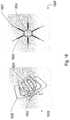
- FIG. 1depicts an embodiment of this present invention, which may include a carousel atop the cooking pot;
- FIG. 2depicts the carousel mechanism shown in FIG. 1 ;
- FIG. 3illustrates an embodiment of this invention, wherein two carousels, one for housing ingredients and one for chopping ingredients, are placed atop a cooking pot;
- FIG. 4illustrates an embodiment of this invention wherein a container with a rotating dispenser knob is used in combination with the carousel mechanism of FIG. 1 ;
- FIG. 5illustrates an embodiment of this invention, namely an actuation mechanism for ingredient dispenser containers
- FIG. 6Aillustrates an embodiment of this invention, which is an apparatus for chopping ingredients
- FIG. 6Billustrates an embodiment of this invention, which is an apparatus for dicing ingredients
- FIG. 7illustrates an embodiment of this invention, which uses a series of links to move a stirrer to various positions
- FIG. 8illustrates an embodiment of this invention, which may dispense solid ingredients
- FIG. 9illustrates an embodiment of this invention, wherein food is prevented from sticking on to the sides of the ingredient container by reducing the surface area of contact between the ingredient container and the food;
- FIG. 10A and FIG. 10Billustrate embodiments of this invention, wherein the mechanism for dispensing and sensing is described;
- FIG. 11illustrates an embodiment of this invention, wherein the mechanism for dispensing food is described
- FIG. 12A and FIG. 12Billustrate embodiments of this invention that dispense liquids
- FIG. 13illustrates an embodiment of this invention that shows a mass sensor system
- FIG. 14illustrates an embodiment of this invention that shows a system capable processing various types of food
- FIG. 15illustrates an embodiment of this invention that shows the system for placing the salad bowl or pizza base or cooking pot and heater or tortilla (for making burritos) and in general for placing the base that is processed further;
- FIG. 16illustrates an embodiment of this invention that illustrates a modular ingredient container and shows how it may be attached to a carousel;
- FIG. 17illustrates an embodiment of this invention, that shows how modular ingredient containers may be attached to each other;
- FIG. 18illustrates an embodiment of this invention, a paddle for dispensing ingredients
- FIG. 19illustrates an embodiment of this invention, a bearing for ingredient containers
- FIGS. 20A-20Cillustrate an embodiment of this invention, which show how magnets and Hall sensors may be structured for dispensing material from ingredient containers;
- FIG. 21illustrates an issue with a proposed dispensing system, wherein vertical knobs can collide with an actuator used for dispensing;
- FIG. 22illustrates an embodiment of this invention, that shows how a knob may be straightened with a “knob straightener mechanism”
- FIG. 23illustrates an embodiment of this invention, that shows how a robot may be controlled using a touchscreen user interface
- FIGS. 24A-24Billustrate an embodiment of this invention, which show how thermal insulation is provided between the chamber where ingredients are kept and other portions of the apparatus;
- FIG. 25illustrates an embodiment of this invention, which shows how a container may be used for providing thermal insulation by closing the hole where ingredients drop;
- FIGS. 26A-26Cillustrate an embodiment of this invention, which show a mechanism for opening and closing a hole where ingredients drop;
- FIG. 27illustrates an embodiment of this invention, which shows a method to dispense ingredients.
- FIG. 28illustrates an embodiment of this invention, which shows an apparatus for dispensing liquids.
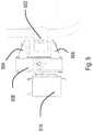
- FIG. 1describes an embodiment of this present invention, which may be a robotic cooking apparatus or food preparation machine/apparatus.
- a robotic cooking apparatusmay include outer container 100 , inner container 102 , carousel 104 , shaft 106 , pan 108 , stirrer 110 , robot arm 112 , X rail 114 , Y rail 116 , motor 118 , plate 120 , and heater 122 .
- Foodmay be stored in ingredient dispenser containers such as outer container 100 and inner container 102 .
- the terms tube and canistermay also be used to refer to containers at various sections of this patent application.
- Ingredient dispenser containers outer container 100 and inner container 102may be mounted on to a carousel 104 which may be attached to a rotating shaft 106 .
- the shaft 106may be rotated with the help of a motor.
- Several mechanismsmay be used for rotating containers placed in a circular configuration, which may be placed on a circular board/platform.
- FIG. 1two circular rows of ingredient dispensers are depicted, with outer container 100 on the outer circular row and inner container 102 on the inner circular row.
- a number of circular rowsmay be designed and utilized, and may range from at least 1 to 10.
- the carousel 104may be placed atop the pan 108 where cooking may happen.
- Pan 108may be called pot, cooking pot, cooking pan, or cooking vessel herein.
- the carousel 104may include openings (not shown), including substantially circular and other shapes, for dispensing food from ingredient containers outer container 100 and inner container 102 , and other containers.
- a heatersuch as, for example, an induction heater 122 , may be used to cook a dish. It may include a stirrer 110 which may be moved in X and Y dimensions (with respect to pan 108 ) using robot mechanisms which may include round shafts or rails such as X rail 114 and Y rail 116 . Stirrer 110 may also be designed to move in the Z dimension and various angles/combinations of X, Y and Z. A motor 118 may be used for rotating the stirrer 110 . Several variations of these embodiments are possible. For example, the stirrer 110 may be attached to a polar robot mechanism.
- Polar mechanismsmay provide improved resistance to cooking grease related reliability issues since they may be easier to seal.
- Cooking pan 108 and heater 122may be moved via moving plate 120 up and down using a robot arm 112 .
- Robot arms shown in FIG. 1may be built using a number of different mechanisms, such as, for example, chains, belts, lead screws, ball screws and many other materials.
- a refrigeration system, a Peltier cooling system or other cooling apparatusmay be utilized to cool the region above the carousel 104 , and efficiency improved by placing components above the carousel 104 in a thermally isolated environment.
- the opening on the carousel which may allow food to be dispensed into the pan 108may be open and closed using a robot arm or other actuation mechanism.
- the plate 120may include a mass sensor which measures the weight of food in the pan. This may provide information about the status of a certain dispensing step i.e. how much food has been dispensed from ingredient dispensers such as outer container 100 and inner container 102 into the pan 108 .
- the mass sensormay optionally also provide information about status of the cooking process—by measuring how much weight reduction happens during the cooking process. It will be clear to one skilled in the art that several variations of these embodiments may be possible.
- an induction heater 122need not be present, and one may dispense ingredients using the robotic cooking apparatus for making salads and other types of food. Sensors (not shown) may be present for estimating if ingredients in containers such as inner container 102 may be spoilt.
- Carousel 104may include more than two rows of containers or just one row of containers. The temperature of the environment in which the carousel with containers is placed can be modulated, for example, using a refrigeration system or a heating system.
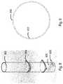
- FIG. 2illustrates a close up view of a design of the carousel described in FIG. 1 .
- Outer containers 200 and inner containers 202may be placed on the carousel 204 which may contain a shaft 206 .
- Placement of outer containers 200 and inner containers 202 on carousel 204may be designed such that their bottom opening may be positioned substantially directly over opening(s) (not shown) in the thermally isolated carousel environment of FIG. 1 .
- a chute configuration(not shown) may alternatively be employed wherein the containers are not substantially directly over the opening(s). Gravity feed as well as motorized movement of the food ingredients from the containers thru the opening(s) to the pan (or other receptacle) may be utilized.
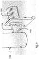
- FIG. 3illustrates an embodiment of this present invention wherein two carousels, upper carousel 300 and lower carousel 302 , may be placed above a cooking pan (not shown).
- the upper carousel 300may be connected to containers having ingredients, such as outer ingredient container 304 and inner ingredient container 306 .
- the lower carousel 302may be connected to choppers such as chopper 308 . Some choppers may contain blades to slice ingredients, some choppers may contain blades to dice ingredients, some choppers may contain blades to shred ingredients and some choppers may have other functions.
- the robotic cooking apparatuscan control which ingredient container is placed above which chopper by rotating individual carousels upper carousel 300 and lower carousel 302 , such that a certain ingredient, or combination of ingredients, may be chopped.
- Several mechanismsmay exist to rotate carousels upper carousel 300 and lower carousel 302 .
- beltssuch as upper belt 312 and lower belt 318 may be used, in combination with pulleys upper carousel pulley 310 , upper motor pulley 314 and lower motor pulley 316 .
- Direct drive and other gearing mechanismsmay also be utilized to rotate upper carousel 300 and lower carousel 302 .
- FIG. 4illustrates an embodiment of this invention, wherein the container shown in FIG. 4 may be used in conjunction with the carousel mechanism of FIG. 1 to dispense controlled amounts of ingredients.
- View 400shows a side view of the container that may be used in the carousel 104 while second view 402 shows an exploded view of the container that may be used in the carousel 104 .
- the containermay include an object such as cylinder 404 for housing the ingredients. Cylinder 404 may have a square or rectangular cross sectional shape, the diameter may increase or decrease in the vertical direction, and the material composition and surface friction coefficient/roughness chosen, depending on design and engineering considerations, for example of the food ingredient type, moisture content, container cleaning/sterilization constraints and so on.
- Shapes such as container side 406may be added to make insertion into a carousel mechanism easier by inserting the shapes into slots on a carousel.
- a shape such as handle 408may be used to dispense controlled amounts of ingredients.
- the exploded second view 402shows more details of the ingredient dispensing mechanism.
- the knob 410When the knob 410 is rotated, the shaft 414 may rotate the paddle 412 .
- the rotational motionmay allow dispensing of controlled amounts of ingredients.
- Paddle 412may be partially constructed of a flexible material, for example, such as silicone. Mass sensors (not shown) may be used in conjunction with this mechanism to determine the amount of ingredient dispensed.
- monitoring the rotational angle (theta) traversed by the knob 410may provide an estimate/measure of the ingredient amount dispensed.
- FIG. 5describes an embodiment of this invention, which illustrates an apparatus for actuating the knob 410 of container cylinder 404 in FIG. 4 herein.
- Knob 402 (or some other projection) of the dispenser containermay be present, and may be indicated as projection 502 .
- a gripper mechanismmay be used to rotate the projection 502 .
- Two arms of the gripper upper arm 504 and lower arm 506may be used to grip and then securely hold the projection 502 .
- the motor 510may be used to rotate the gripper by rotating gripper body 508 . In case some food items get stuck in container cylinder 404 , gripper body 508 may be rotated in the opposite direction.
- Motor 510 and hence gripper body 508may also be run thru an acceleration/deceleration forward/reverse algorithm (for example, creating a vibration) to clear stuck food items.
- an acceleration/deceleration forward/reverse algorithmfor example, creating a vibration
- Several other mechanismsare possible to hold and rotate the projection 502 , for example, utilizing a robotic arm, or single/quad gripper arms.
- FIG. 6Aillustrates an embodiment of this invention, which is an apparatus for chopping ingredients in the carousel mechanism that may be depicted with FIG. 1 .
- Exemplary ingredient containers 600may be placed in carousel 602 .
- Chopping sliders 604may be placed into sockets 606 at the base of ingredient containers so that they can slide back and forth in the sockets 606 .
- Chopping blades 608may chop up ingredients in containers when the chopping sliders 604 are moved in a certain direction.
- Chopping sliders 604may be pushed and pulled using an actuator mechanism (not shown in the figure).
- FIG. 6Bdescribes an embodiment of this invention, which is an apparatus for dicing ingredients in the carousel mechanism that may be depicted with FIG. 1 .
- Exemplary ingredient containers 620may be placed in carousel 622 .
- Chopping sliders 628may be placed into sockets 630 at the base of ingredient containers so that they can slide back and forth in the sockets 630 .
- Dicing grids, such as for example, 624may be placed at the base of ingredient dispensers.
- Ingredientsmay be pushed down the ingredient containers using a plunger mechanism, such as for example, the plunger described.
- the action of ingredients being pushed down the ingredient dispenser into the dicing grid, in combination with the motion of chopping sliders 628together may cause ingredients to be diced and dispensed.
- Chopping sliders 628may also include chopping blades 626 to provide a dual use function.
- FIG. 7illustrates an embodiment of this invention which allows motion of components in a plane based on motion of multiple links first link 706 and second link 708 .
- Motors first link motor 700 and second link motor 702could be used to rotate links first link 706 and second link 708 and thus move a stirrer 710 to various points in a cooking vessel 714 .
- Stirrer motor 704may be utilized to provide other motions of stirrer 710 , for example, rotation clockwise and counterclockwise, specific stirrer blade orientations in combination with link movement and orientation (for example, to provide a scrapping action on the surface of cooking vessel 714 ), and so on.
- the cooking vessel 714may be located atop a heater 716 .
- This type of link based systemcan be used for moving or providing motion to objects and mechanisms other than stirrers, such as, for example, spice dispensers, liquid dispensers and other objects.
- this link based systemmay possible. For example, one could have more links than two, motors may be placed at alternative positions, Z motion and combinations of X, Y, and Z motions, and many other options may be possible.
- FIG. 8illustrates an embodiment of this invention, a solid dispensing apparatus.
- a paddle 806(similar to paddle 412 of FIG. 4 herein) may be present within a food containing tube 802 (which is similar to ingredient containers of at least FIGS. 1-4, 6A and 6B herein).
- the tube 802may be attached to a carousel using collars 804 .
- the knob 808(similar to knob 410 of FIG. 4 herein) may be rotated using the help of a motor to rotate the paddle 806 and in combination with gravity, dispense food.
- the term pinmay also be used to describe the knob at various sections of this patent application.
- the knob 808may be rotated in more than one direction during the dispensing process, as described previously in at least FIG. 4 & related specification sections herein.
- FIG. 9illustrates an embodiment of this invention, which may help reduce sticking of food on the sides of container 802 depicted in FIG. 8 .
- Thismay be done by having non circular sidewalls 912 on the inside of the container so that surface area of contact between the food item and the inside wall is reduced.
- the outside wall 910may be circular.
- Several variations of these embodimentsmay be possible. For example, one could have non-circular inner and outer walls and one may use wave-like patterns or other patterns on the inner walls to reduce sticking. The pattern could be tuned or ‘matched’ to the type and shape of the food ingredient. For example, a vertical wave pattern could be the half or quarter period of the average size (‘wave’) of the food item.
- FIG. 10A and FIG. 10Billustrate an embodiment of this invention, a mechanism to rotate the knob 808 shown in FIG. 8 .
- the motor 1002may be used to rotate a shaft 1008 which may in turn rotate the dispensing mechanism 1006 .
- a magnetmay be used as part of the dispensing mechanism 1006 .
- a hall sensor 1010 shown in FIG. 10Bmay be used to determine the rest position of the knob 808 after the dispense operation is complete.
- FIG. 11illustrates an embodiment of this invention, a mechanism to dispense food, which may include ingredient container 1100 , ingredient container knob 1102 , dispensing knob 1104 and motor 1106 .
- a motor 1106may be used to rotate the dispensing knob 1104 .
- the ingredient container's knob 1102may also rotate. This, in turn, may dispense food ingredients from ingredient container 1100 .
- the term “pin”may be used instead of the term “knob” at various sections of this document.
- FIG. 12A and FIG. 12Billustrate embodiments of this invention, a liquid dispensing system, which may include pin 1202 , ingredient container 1204 , spacer 1206 , cam mechanism 1208 , shaft 1210 , ingredient container knob 1212 , pin 1214 , head 1216 and spout 1218 .
- the ingredient container knob 1212may be rotated, the cam mechanism 1208 may be pushed up on the spacer 1206 .
- the spout 1218may dispense the ingredient from the container 1204 using a pump mechanism.
- a one way valvemay be added to the end of the spout 1218 to reduce dripping of the liquid when dispensing action is not required.
- FIG. 13illustrates an embodiment of this invention, a mass sensor scheme, which may include load cell 1302 , mass measuring system 1304 and bowl 1306 .
- a load cell 1302may be used and attached to a mass measuring system 1304 .
- the motor for dispensing the ingredientmay be turned to OFF position.
- the mass sensor system shown in FIG. 13is isolated from the food zone where the salad bowl or cooking container or induction heater may be placed.
- the bowl 1306may be placed such that it is isolated from wires associated with the load cell 1302 .
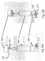
- FIG. 14is an illustration of an embodiment of this invention which illustrates a food system 1499 , part of a robotic cooking apparatus, capable of helping make pizza, cook food, make burritos, make salads and make several other types of food.
- Food system 1499may include plate 1402 , second link motor 1404 , first link motor 1406 , compartment 1408 , ingredient containers 1410 , carousel 1412 and dispenser motor 1414 .
- Ingredientsmay be placed in ingredient containers 1410 (one shown for clarity) and may be dispensed using motion of the carousel 1412 and dispensing mechanisms which use dispenser motors such as, for example, dispenser motor 1414 .
- the dispensing mechanismsmay be shared among multiple containers to lower cost and weight of the food making machine.
- the pizza basemay be placed on the plate 1402 .
- the plate 1402may be moved using a multi-link mechanism which in turn may move based on motion of motors second link motor 1404 , first link motor 1406 and additional motors placed in compartment 1408 .
- Ingredientsmay be dropped on the pizza base using technologies described in FIG. 1 - FIG. 13 herein.
- the pizza basemay be moved using motion of the plate 1402 to distribute the ingredients over the pizza area.
- the tortillamay be placed on the plate 1402 and ingredients may be dispensed atop it.
- the salad bowlmay be placed on the plate 1402 and ingredients may be dispensed atop it.
- an induction heater and the potmay be placed atop the plate 1402 and ingredients may be dispensed into the pot.
- An additional robot armmay be used to stir the food.
- the robot armmay be designed as a Cartesian robot system with a stirrer at the end or using a technique similar to the one described in FIG. 7 herein or using some other technique.
- FIG. 15is an illustration of an embodiment of this invention, which illustrates a closer view of the mechanism for moving the plate 1402 of FIG. 14 .
- the plate 1502may be moved using motion of links third link 1506 , second link 1510 and first link 1512 .
- the motors third link motor 1504 and second link motor 1508may rotate to move links third link 1506 and second link 1510 and thereby move the plate 1502 in the horizontal plane.
- the first link 1512may move up and down via motors placed within compartment 1514 .
- Several other mechanismsmay provide movement to the plate 1502 in the X, Y, Z plane and dispense ingredients onto it. For example, placing plate 1502 on a 3D motion table.
- FIG. 16is an illustration of an embodiment of this invention that describes a modular ingredient container and shows how it may be attached to a carousel.
- the modular ingredient container 1642(and blow-up 1640 ) may consist of two or more portions (such as, for example, upper portion 1623 and lower portion 1624 ) that may be attached to each other using a latch mechanism 1644 .
- Using modular ingredient containersis an innovation that provides several benefits: (1) If one wants to increase food capacity of the apparatus, one more modular ingredient container portions can be added to provide extra capacity (2) A big size ingredient container, when split into two smaller ingredient containers, is easier to fit into a dishwasher or sink for cleaning purposes.
- the modular ingredient containersmay be attached to carousel 1625 using various mechanisms.
- Modular ingredient containersmay also be attached to carousel 1625 using clip mechanisms, wherein a clip 1628 may be used to attach to a portion of an ingredient container such as location 1620 .
- a portion of an ingredient containeris attached to a clip 1622 .
- Several alternative mechanismsmay be possible to attach an ingredient container to the carousel. For example, magnets, for example a combination of permanent and electromagnets may be used. Pins, such as for example, cotter pins 1632 may be used to make sure a shaft used in the canister does not slip out.
- FIG. 17is an illustration of an embodiment of this invention how different portions of an ingredient container may be attached to each other.
- Projectionssuch as first projection 1712 , second projection 1713 , third projection 1710 and fourth projection 1714 may be added to ingredient container portions upper portion 1717 and lower portion 1716 which may need to be attached to each other.
- a joinermay be added that may consist of parts such as flap 1715 , elastic flap 1711 and stem 1720 .
- the elastic flap 1711may allow for a good fit despite the manufactured tolerance of various parts. It may consist of a flexible material that can deform to allow a good fit. Examples of flexible materials may include silicone rubber, polyurethane and many other materials.
- the stem 1720 , flap 1715 and other parts of the joinermay consist of non-flexible materials so that multiple parts of an ingredient container are closed securely, without leakage of material.
- materials for this applicationmay include polycarbonate, PVC and many other materials.
- the ingredient containersmay be open or closed by moving joiners into open or closed positions.
- FIG. 17includes locked position 1718 and unlocked position 1719 illustrations. At various sections of this patent application, the term latch may be used in place of the term joiner.
- FIG. 18is an illustration of an embodiment of this invention how paddles may be designed for use in the ingredient containers.
- the paddlesmay, for example, be constructed of similar or multiple different materials for core 1834 and external portions first extension 1830 and second extension 1831 .
- the core 1834may primarily include a non-flexible plastic, such as, for example, polycarbonate, PVC or other suitable non-flexible plastic.
- the external portions first extension 1830 and second extension 1831may have flexible materials, such as, for example, silicone rubber, polyurethane or some such material.
- the external portion first extension 1830may be thicker than the external portion second extension 1831 . This could provide the most effective combination of stiffness and flexibility for dispensing specific ingredients.
- the external portions first extension 1830 and second extension 1831may be overmolded atop the core 1834 .
- Holes 1832may be inserted into the core 1834 to allow more convenient overmolding.
- FIG. 19is an illustration of an embodiment of this invention how bearings may be used to provide long-term reliability to containers.
- shafts 1933When shafts 1933 are inserted into containers 1936 and rotated over long-periods of time to dispense ingredients, plastic used in containers 1936 may degrade and/or wear away.
- bearings outer bearing 1940 and inner bearing 1938By inserting bearings outer bearing 1940 and inner bearing 1938 into the ingredient container 1936 , the reliability challenges may be reduced.
- Various types of bearings and materials for bearingsmay be possible, and could reduce friction, degradation or wear.
- FIGS. 20A-20Cillustrate an embodiment of this invention, wherein multiple hall sensors and magnets may be placed within a dispenser motor assembly to more accurately dispense ingredients.
- FIG. 20Aindicates a dispensing actuator arm 2004 , a motor shaft 2006 that rotates actuator arm 2004 , a plate 2008 and a motor cover 2002 .
- Two Hall Sensors sensor one 2010 and sensor two 2012may be used to detect the location of the actuator arm 2014 based on position of magnets top magnet 2016 and bottom magnet 2018 . When a magnet is directly above a sensor during rotational motion of actuator arm 2014 , the sensor may indicate it and give feedback to the control PCB on location of the actuator arm.
- Various types of sensorsmay be possible, not just Hall sensors. Magnets may be of various shapes, sizes and types. More than two Hall sensors may be used. A single Hall sensor architecture may be used as well. Alternatively, an encoder may be used in the motor to indicate its position.
- FIG. 21illustrates an issue that arises when using a pin-dispenser rod actuator system 2106 .
- the pin 2102 and actuator arm 2104may be aligned in the same direction and could crash during motion of a carousel. This needs to be avoided for proper system operation.
- FIG. 22illustrates an embodiment of this invention, a system for aligning pin 2204 so that it does not collide with the actuator arm shown in FIG. 21 .
- a pin straightener 2202may be placed in the apparatus. When the carousel rotates, pins 2204 may be automatically aligned into a horizontal direction due to engagement with the pin straightener 2202 .
- FIGS. 23A-23Billustrate an embodiment of this invention, wherein a touchscreen may be used to control the operation of a food preparation/robotic cooking apparatus having one of more of the features indicated in FIG. 1-22 and FIG. 24-28 .
- the touchscreen 2308may be placed within door 2306 , as indicated in FIG. 23B .
- FIG. 23Aindicates the back side of the door 2304 and view 2302 indicates an exemplary carousel system with exemplary canisters loaded on it. Customers may use the touchscreen 2308 to indicate their food choices and the apparatus indicated in FIG. 23A-B may prepare the food.
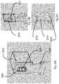
- FIG. 24A-Billustrates an embodiment of this invention, which is a system for thermally insulating the food storage chamber of the apparatus.
- the systemmay consist of an insulation canister 2404 meant for insulation purposes.
- One position of the insulation canister 2404may be indicated in FIG. 24A , where the insulation layer 2406 does not contact the food opening 2402 i.e. the food opening is unsealed.
- Another position of the insulation canister 2404may be indicated in FIG. 24B wherein the insulation layer 2406 may contact the food opening 2402 , seal it and prevent significant heat from entering the chamber.
- the insulation layer 2406may include a good insulator, such as, for example, silicone or some other insulation material.
- the insulation layer 2406may also include a material which has some flexibility so that it gives a tight fit to the food opening 2402 .
- a carouselmay move the canister meant for insulation (insulation canister 2404 ) directly above the food opening 2402 and keep the food storage chamber insulated.
- shape of canisters, insulation layers and food openingsmay be different than illustrated.
- Insulation canistermay also contain some insulative material in addition to insulation layer 2406 .
- FIG. 25illustrates different portions of the insulation canister described in FIGS. 24A-24B .
- the canistermay be composed of two portions, upper portion 2502 and lower portion 2504 , for example.
- the insulation layer 2506may be connected to a mechanism within the insulation canister using pieces 2508 .
- FIGS. 26A-26Cillustrates a simplified view of the internal mechanism within an insulation canister. It will be clear to one skilled in the art that the mechanism shown in FIG. 26A-26C is exemplary, and several variations may exist.
- An insulation layer 2606may be connected to a platform 2604 that moves within a canister.
- a pin 2610may be rotated with a dispensing actuator similar to those described earlier in this patent application.
- the pinmay actuate a mechanism consisting of a cam 2614 using a shaft.
- FIG. 26Bmay illustrate one position of the mechanism, where the portion 2616 of cam 2614 may come in contact with the wall 2618 .
- a wheel 2612may allow smooth motion of the cam 2614 .
- the platform 2604is not shown in FIG. 26B-26C to better illustrate the working of the mechanism.
- FIG. 26Cmay illustrate another position of the mechanism, where the cam 2620 may be in another stable position.
- One of the key factors of the invention shown in FIG. 26A-26Cis the fact that the cam 2614 may be in two stable positions.
- insulation layer 2606This provides a stable open and closed position of insulation layer 2606 , ‘closed’ with respect to food opening 2402 when actuated ‘down’, and ‘open’ with respect to food opening 2402 when the cam position pulls insulation layer 2606 ‘up’ so that the insulation canister 2404 can rotate freely on the carousel.
- the insulation canistermay be operated by the same motor/cam system as the normal food dispensing operation.
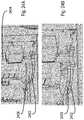
- FIG. 27illustrates an embodiment of this invention, wherein ingredients sticking to the walls of the ingredient container/canister may be reduced by using fittings 2704 within the canister.
- fittings 2704may be actuated by motion of the paddles 2710 .
- the fittings 2704may be attached to the top of canisters 2708 or the sides of canisters 2709 . They may have multiple pieces, for example, with one portion fitting bottom 2707 contacting the paddle and another portion fitting top 2704 contacting top of canisters 2708 .
- the paddlerotates, it may move the fittings back and forth by contacting fitting bottom 2707 and causing motion within the canister which may allow ingredients stuck to the sides of canisters to come unstuck.
- Snapshot one 2700illustrates fitting 2704 with no paddles 2710 contact
- snapshot two 2701illustrates fitting 2704 contacting paddles 2710 to one side
- snapshot three 2702illustrates fitting 2704 contacting paddles 2710 to the other side.
- the shape of the fittingsmay be different—it could be the shape of a curtain.
- the fittingsmay be attached to the sides of the canister instead of the center as shown in FIG. 27 .
- the fittingsmay include a hinge. Several other variations may be possible.
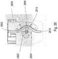
- FIG. 28illustrates an embodiment of this invention, which shows an apparatus for dispensing liquids.
- the liquid to be dispensedmay be stored in a bottle located within a canister 2806 and a flexible tube 2800 may lead from it.
- the flexible tubemay be compressed by rollers such as 2802 and 2804 to control the dispensing of the liquid.
- a one way valvemay be optionally added to the end of the tube 2810 to reduce dripping of liquid in unwanted locations.
- the rollers 2802 and 2804may move using rotation of shaft 2812 , which in turn may be rotated using a shared dispensing apparatus that may be connected to a pin located on the canister 2806 .
- references to “one embodiment,” “an embodiment,” “example embodiment,” “various embodiments,” etc.,may indicate that the embodiment(s) of the invention so described may include a particular feature, structure, or characteristic, but not every embodiment necessarily the particular feature, structure, or characteristic.
- processormay refer to any device or portion of a device that processes electronic data from registers and/or memory to transform that electronic data into other electronic data that may be stored in registers and/or memory.
- a “computing platform”may comprise one or more processors.
- Embodiments of the present inventionmay include apparatuses for performing the operations herein.
- An apparatusmay be specially constructed for the desired purposes, or it may comprise a general purpose device selectively activated or reconfigured by a program stored in the device.
Landscapes
- Engineering & Computer Science (AREA)
- Food Science & Technology (AREA)
- Robotics (AREA)
- Mechanical Engineering (AREA)
- Life Sciences & Earth Sciences (AREA)
- Food-Manufacturing Devices (AREA)
Abstract
Description
Claims (23)
Priority Applications (12)
| Application Number | Priority Date | Filing Date | Title |
|---|---|---|---|
| US15/449,548US10813503B2 (en) | 2014-09-09 | 2017-03-03 | Automated food making apparatus |
| US15/945,483US11284748B2 (en) | 2014-09-09 | 2018-04-04 | Enhanced automated food making apparatus |
| RU2019130974ARU2019130974A (en) | 2017-03-03 | 2018-04-04 | ADVANCED AUTOMATED COOKER |
| PCT/US2018/026065WO2018161096A2 (en) | 2017-03-03 | 2018-04-04 | An enhanced automated food making apparatus |
| EP18761194.2AEP3589169B1 (en) | 2017-03-03 | 2018-04-04 | An enhanced automated food making apparatus |
| CA3055291ACA3055291A1 (en) | 2017-03-03 | 2018-04-04 | An enhanced automated food making apparatus |
| US16/933,130US11918149B2 (en) | 2014-09-09 | 2020-07-20 | Enhanced automated food making apparatus |
| US16/934,447US12082749B2 (en) | 2014-09-09 | 2020-07-21 | Automated food making apparatus |
| US17/359,191US11918150B2 (en) | 2014-09-09 | 2021-06-25 | Enhanced automated food making apparatus |
| US17/382,907US12022982B2 (en) | 2014-09-09 | 2021-07-22 | Enhanced automated food making apparatus |
| US18/395,355US12318044B2 (en) | 2014-09-09 | 2023-12-22 | Automated food making apparatus |
| US18/444,469US12408799B2 (en) | 2014-09-09 | 2024-02-16 | Enhanced automated food making apparatus |
Applications Claiming Priority (9)
| Application Number | Priority Date | Filing Date | Title |
|---|---|---|---|
| US201462047785P | 2014-09-09 | 2014-09-09 | |
| US201462056368P | 2014-09-26 | 2014-09-26 | |
| US201462094595P | 2014-12-19 | 2014-12-19 | |
| US201562150303P | 2015-04-21 | 2015-04-21 | |
| US201562185524P | 2015-06-26 | 2015-06-26 | |
| US201562201105P | 2015-08-04 | 2015-08-04 | |
| US14/847,959US20160067866A1 (en) | 2014-09-09 | 2015-09-08 | Automated cooking machine using a cartesian bot |
| US201662304277P | 2016-03-06 | 2016-03-06 | |
| US15/449,548US10813503B2 (en) | 2014-09-09 | 2017-03-03 | Automated food making apparatus |
Related Parent Applications (1)
| Application Number | Title | Priority Date | Filing Date |
|---|---|---|---|
| US14/847,959Continuation-In-PartUS20160067866A1 (en) | 2014-09-09 | 2015-09-08 | Automated cooking machine using a cartesian bot |
Related Child Applications (2)
| Application Number | Title | Priority Date | Filing Date |
|---|---|---|---|
| US15/945,483Continuation-In-PartUS11284748B2 (en) | 2014-09-09 | 2018-04-04 | Enhanced automated food making apparatus |
| US16/934,447ContinuationUS12082749B2 (en) | 2014-09-09 | 2020-07-21 | Automated food making apparatus |
Publications (2)
| Publication Number | Publication Date |
|---|---|
| US20170172351A1 US20170172351A1 (en) | 2017-06-22 |
| US10813503B2true US10813503B2 (en) | 2020-10-27 |
Family
ID=59065321
Family Applications (3)
| Application Number | Title | Priority Date | Filing Date |
|---|---|---|---|
| US15/449,548Active2037-03-06US10813503B2 (en) | 2014-09-09 | 2017-03-03 | Automated food making apparatus |
| US16/934,447Active2035-11-02US12082749B2 (en) | 2014-09-09 | 2020-07-21 | Automated food making apparatus |
| US18/395,355ActiveUS12318044B2 (en) | 2014-09-09 | 2023-12-22 | Automated food making apparatus |
Family Applications After (2)
| Application Number | Title | Priority Date | Filing Date |
|---|---|---|---|
| US16/934,447Active2035-11-02US12082749B2 (en) | 2014-09-09 | 2020-07-21 | Automated food making apparatus |
| US18/395,355ActiveUS12318044B2 (en) | 2014-09-09 | 2023-12-22 | Automated food making apparatus |
Country Status (1)
| Country | Link |
|---|---|
| US (3) | US10813503B2 (en) |
Cited By (1)
| Publication number | Priority date | Publication date | Assignee | Title |
|---|---|---|---|---|
| US12075948B2 (en) | 2022-06-13 | 2024-09-03 | DoorDash, Inc. | Apparatuses and methods for improved ingredient dispensing |
Families Citing this family (13)
| Publication number | Priority date | Publication date | Assignee | Title |
|---|---|---|---|---|
| US11918150B2 (en) | 2014-09-09 | 2024-03-05 | DoorDash, Inc. | Enhanced automated food making apparatus |
| US10813503B2 (en) | 2014-09-09 | 2020-10-27 | Casabots Inc. | Automated food making apparatus |
| US11284748B2 (en) | 2014-09-09 | 2022-03-29 | Chowbotics | Enhanced automated food making apparatus |
| WO2017155829A2 (en)* | 2016-03-06 | 2017-09-14 | Kathirasen Kathirgugan | An automated food making apparatus |
| WO2018161096A2 (en)* | 2017-03-03 | 2018-09-07 | Chowbotics | An enhanced automated food making apparatus |
| WO2019097545A1 (en)* | 2017-11-15 | 2019-05-23 | Cohan Sujay Carlos | Cooking robot for the home |
| US20190193263A1 (en)* | 2017-12-22 | 2019-06-27 | Sridhar Raidi | Single compact robotic food making apparatus |
| US11613025B2 (en) | 2018-10-12 | 2023-03-28 | Truebird Technologies, Inc. | Isolating robotic actuators from food and beverage preparation |
| USD933438S1 (en)* | 2019-10-23 | 2021-10-19 | Lg Electronics Inc. | Bowl holder for a cooking robot |
| GB202018946D0 (en)* | 2020-12-01 | 2021-01-13 | Karakuri Ltd | Karakuri Big Book |
| CN217429739U (en)* | 2021-06-03 | 2022-09-16 | 添可智能科技有限公司 | Cooking equipment and prevent burnt pot cooking equipment |
| WO2023039042A1 (en)* | 2021-09-09 | 2023-03-16 | The Vollrath Company, L.L.C. | Systems and methods for providing touchless food service |
| DE102022101671B4 (en) | 2022-01-25 | 2024-10-10 | Ivan Galant | Feeding unit, automated device and method for preparing food |
Citations (31)
| Publication number | Priority date | Publication date | Assignee | Title |
|---|---|---|---|---|
| GB588616A (en) | 1944-08-24 | 1947-05-29 | Ferranti Ltd | Improvements relating to processes and apparatus for the drying of grain, seed or other granular material |
| US4058120A (en) | 1976-06-29 | 1977-11-15 | Air Products And Chemicals, Inc. | Vaporizer carousel for anesthesia machine |
| US4751878A (en) | 1986-11-28 | 1988-06-21 | Deering Ice Cream Corp. | Manufacture of decorative ice cream rolls |
| EP0455477A2 (en) | 1990-05-04 | 1991-11-06 | Restaurant Technology , Inc. | Food preparation system and method |
| US5955118A (en) | 1997-10-02 | 1999-09-21 | J & J Snack Foods Corp. | Apparatus and method for manufacturing twisted pretzels |
| US6029828A (en) | 1996-11-01 | 2000-02-29 | Robbins Industries, Inc. | Turntable storage device |
| US6533105B1 (en) | 1998-06-04 | 2003-03-18 | Reginald Vernon Dutschke | Grain augers and the like |
| US20030234264A1 (en) | 2002-06-25 | 2003-12-25 | Ofer Landau | Dry food dispensing system |
| US20040129740A1 (en)* | 2003-01-02 | 2004-07-08 | Barker Edward E. | Container for dispensing comestibles |
| US20040159244A1 (en) | 2003-02-18 | 2004-08-19 | Leason David G. | Electric wok having food processor with automatic feed |
| US20050194403A1 (en) | 2004-02-27 | 2005-09-08 | Mink Johannes H. | Fluid and hair-dye dispensers |
| US20050193901A1 (en) | 2004-02-18 | 2005-09-08 | Buehler David B. | Food preparation system |
| WO2006053507A1 (en) | 2004-11-22 | 2006-05-26 | Xiaoyong Liu | Intellectualized cooking method |
| CN2812591Y (en) | 2005-07-07 | 2006-09-06 | 河南兴泰科技实业有限公司 | Multipurpose rotary filler |
| US7174830B1 (en) | 2003-06-05 | 2007-02-13 | Dawei Dong | Robotic cooking system |
| US20070119688A1 (en) | 2003-07-17 | 2007-05-31 | Brandt Edward O | Grain Cart and Auger Construction |
| US7267833B2 (en) | 2002-12-02 | 2007-09-11 | Samsung Electronics Co., Ltd. | Apparatus and method of automatic cooking of buckwheat |
| JP4136297B2 (en) | 2000-09-06 | 2008-08-20 | 株式会社 ワイ・エム・エス | Powder storage hopper |
| US20080282904A1 (en) | 2005-01-12 | 2008-11-20 | Xiaoyong Liu | Automatic or Semi-Automatic Turning Method and Device |
| US20100126285A1 (en) | 2006-08-18 | 2010-05-27 | John Caroll | Method and apparatus for dispensing powder samples |
| US20110027914A1 (en)* | 2009-07-29 | 2011-02-03 | Dynex Technologies | Sample plate systems and methods |
| US20110108546A1 (en) | 2009-11-09 | 2011-05-12 | Delta Electronics, Inc. | Intelligent heater and temperature measuring device |
| US20120288973A1 (en) | 2010-01-08 | 2012-11-15 | Mtek-Smart Corporation | Dispensing method and dispensing apparatus |
| US20130112683A1 (en) | 2010-07-15 | 2013-05-09 | Breville Pty Limited | Multi Cooker |
| US20130192527A1 (en)* | 2012-01-31 | 2013-08-01 | Wayland Reid | Gravity fed automatic rotary vein dispenser |
| US20140230660A1 (en) | 2013-02-19 | 2014-08-21 | Zhengxu He | Scalable automated cooking system having small footprint and reduced labor cost |
| US20150075391A1 (en)* | 2012-06-06 | 2015-03-19 | Momentum Machines Company | System and method for dispensing toppings |
| US20150208871A1 (en)* | 2011-03-25 | 2015-07-30 | Ping-Hua CHANG | Automatic Cooking Apparatus |
| US20160067866A1 (en) | 2014-09-09 | 2016-03-10 | Casabots Inc. | Automated cooking machine using a cartesian bot |
| US20170172351A1 (en) | 2014-09-09 | 2017-06-22 | Casabots Inc. | Automated food making apparatus |
| US10064521B1 (en)* | 2014-01-15 | 2018-09-04 | Yantra, Llc | Automated multi-dish cooking machine |
Family Cites Families (46)
| Publication number | Priority date | Publication date | Assignee | Title |
|---|---|---|---|---|
| US3277356A (en) | 1963-12-12 | 1966-10-04 | Harold D Kraft | Pump arrangement for dispensing predetermined quantities of liquid |
| US4335761A (en)* | 1980-07-21 | 1982-06-22 | Fci, Inc. | Reciprocal bottle filling device |
| US4503502A (en) | 1983-06-03 | 1985-03-05 | Chapin Roger A | Method and apparatus for automated chinese stir-fry cooking |
| US4715517A (en) | 1986-06-26 | 1987-12-29 | Go-Jo Industries, Inc. | Dispenser having a roller for squeezing material from a tube |
| US4748902A (en) | 1987-01-21 | 1988-06-07 | Vito Maurantonio | Automatic food cooker and dispenser |
| JPH07100112B2 (en) | 1987-03-14 | 1995-11-01 | 株式会社東芝 | Detergent supply device for washing machines |
| JP3403010B2 (en) | 1996-07-12 | 2003-05-06 | キヤノン株式会社 | Liquid ejection head |
| US6131766A (en) | 1996-08-12 | 2000-10-17 | Restaurant Automation Development Inc. | System for dispensing controlled amounts of flowable material from a flexible container |
| AU738500B2 (en) | 1997-02-21 | 2001-09-20 | Taco Bell Corp. | Restaurant food preparation line |
| US6332100B1 (en) | 1998-03-24 | 2001-12-18 | Interactive Medical Developments, L.C. | Apparatus and method for medication dispensing and messaging |
| US6062438A (en) | 1998-04-20 | 2000-05-16 | Mars, Inc. | Apparatus for dispensing of bulk product |
| BE1012762A3 (en) | 1999-06-23 | 2001-03-06 | Fountain Ind Europ S A | Delivery device / products dosage. |
| IT1307830B1 (en) | 1999-12-23 | 2001-11-19 | Vales Maria Pilar Perez | AUTOMATED EQUIPMENT FOR THE SALE OF GRANULAR PRODUCTS SUCH AS COFFEE OR OTHER. |
| WO2002051294A2 (en) | 2000-12-26 | 2002-07-04 | Kimberly-Clark Worldwide, Inc. | Dispensing cartridge and system |
| HK1052112A2 (en) | 2002-06-25 | 2003-08-15 | 陈永坚 | Improved food processing apparatus |
| US20060011141A1 (en) | 2004-07-16 | 2006-01-19 | Bird Charles R | Feed hopper |
| EP1817237A4 (en) | 2004-12-04 | 2016-08-31 | Medical Instill Tech Inc | One-way valve, apparatus and method of using the valve |
| CN1739477A (en) | 2005-07-21 | 2006-03-01 | 高春平 | Automatic personalized health article preparing system |
| US7651010B2 (en) | 2005-09-23 | 2010-01-26 | Nestec S.A. | Food dispenser with pump for dispensing from a plurality of sources |
| US7527078B2 (en)* | 2005-10-13 | 2009-05-05 | Fluid Management, Llc | Apparatuses for dispensing materials volumetrically and gravimetrically based on a stored formula and methods of dispensing formulas using the same |
| EP1808404A1 (en) | 2006-01-12 | 2007-07-18 | Sencotel S.L. | Dispensing device for a dispensing machine |
| US9146564B2 (en)* | 2006-03-06 | 2015-09-29 | Deka Products Limited Partnership | Product dispensing system |
| EP2155572B1 (en) | 2007-05-07 | 2012-02-29 | Marek Szymanski | Liquid dispensing apparatus |
| JP5116461B2 (en) | 2007-12-28 | 2013-01-09 | ホシザキ電機株式会社 | Beverage dispenser |
| AU2009285598B2 (en) | 2008-08-28 | 2015-07-02 | Deka Products Limited Partnership | Product dispensing system |
| GB0819220D0 (en)* | 2008-10-21 | 2008-11-26 | Laliberte Jean Charles | Automatic food dispenser |
| JP5792628B2 (en) | 2008-12-08 | 2015-10-14 | イノディス コーポレーションEnodis Corporation | Device and method for creating beverage recipes for an integrated system for dispensing and formulating / mixing beverage ingredients |
| CA2755629A1 (en) | 2009-04-01 | 2010-10-07 | Stefano Ognissanti | Dispenser of disposable plates for food and related disposable plate |
| US20100276442A1 (en) | 2009-05-01 | 2010-11-04 | Whirlpool Corporation | Personalized dry or bulk dispensing system |
| WO2011060337A2 (en) | 2009-11-15 | 2011-05-19 | Legupro | Liquid movement and control within a container for food preparation |
| US9295281B2 (en) | 2012-06-06 | 2016-03-29 | Momentum Machines Company | System and method for dispensing toppings |
| US9295282B2 (en) | 2012-06-06 | 2016-03-29 | Momentum Machines Company | System and method for dispensing toppings |
| GB2504289A (en) | 2012-07-24 | 2014-01-29 | Rifat Jan | Paste dispenser and paste receiving pouches |
| US9867387B2 (en) | 2012-08-16 | 2018-01-16 | Sunbeam Products, Inc. | Frozen beverage blending and dispensing appliance |
| US20140131384A1 (en) | 2012-11-12 | 2014-05-15 | Jose L MARTINEZ | Personal Cereal Dispenser |
| FR2998890B1 (en) | 2012-12-04 | 2015-08-14 | Gervais Danone Sa | METHOD AND APPARATUS FOR PRESERVING AND DISPENSING A FOOD PRODUCT, IN PARTICULAR A YOGHURT |
| US10017371B2 (en) | 2013-11-13 | 2018-07-10 | TRV Dispense, LLC | Soft food and beverage dispenser |
| US9505600B2 (en) | 2013-11-13 | 2016-11-29 | TRV Dispense, LLC | Soft food and beverage dispenser |
| CN103919491B (en) | 2014-04-25 | 2016-09-07 | 珠海优特电力科技股份有限公司 | A kind of condiment automatically configures device |
| JP6805146B2 (en) | 2014-08-28 | 2020-12-23 | ティーボット インコーポレイテッド | Systems and methods for automatic distribution |
| US11284748B2 (en) | 2014-09-09 | 2022-03-29 | Chowbotics | Enhanced automated food making apparatus |
| US11918150B2 (en) | 2014-09-09 | 2024-03-05 | DoorDash, Inc. | Enhanced automated food making apparatus |
| CN204625150U (en) | 2015-05-05 | 2015-09-09 | 惠尔明(福建)化学工业股份有限公司 | A kind of automatic gauge paint filling equipment accurately |
| EP3178780B1 (en)* | 2015-12-07 | 2018-10-10 | Nestec S.A. | Apparatus for filling containers |
| US9862001B2 (en) | 2015-12-31 | 2018-01-09 | Sulzer Mixpac Ag | Dispensing device |
| AU2017248224A1 (en) | 2016-04-08 | 2018-11-15 | Zume, Inc. | On-demand robotic food assembly and related systems, devices and methods |
- 2017
- 2017-03-03USUS15/449,548patent/US10813503B2/enactiveActive
- 2020
- 2020-07-21USUS16/934,447patent/US12082749B2/enactiveActive
- 2023
- 2023-12-22USUS18/395,355patent/US12318044B2/enactiveActive
Patent Citations (32)
| Publication number | Priority date | Publication date | Assignee | Title |
|---|---|---|---|---|
| GB588616A (en) | 1944-08-24 | 1947-05-29 | Ferranti Ltd | Improvements relating to processes and apparatus for the drying of grain, seed or other granular material |
| US4058120A (en) | 1976-06-29 | 1977-11-15 | Air Products And Chemicals, Inc. | Vaporizer carousel for anesthesia machine |
| US4751878A (en) | 1986-11-28 | 1988-06-21 | Deering Ice Cream Corp. | Manufacture of decorative ice cream rolls |
| EP0455477A2 (en) | 1990-05-04 | 1991-11-06 | Restaurant Technology , Inc. | Food preparation system and method |
| US6029828A (en) | 1996-11-01 | 2000-02-29 | Robbins Industries, Inc. | Turntable storage device |
| US5955118A (en) | 1997-10-02 | 1999-09-21 | J & J Snack Foods Corp. | Apparatus and method for manufacturing twisted pretzels |
| US6533105B1 (en) | 1998-06-04 | 2003-03-18 | Reginald Vernon Dutschke | Grain augers and the like |
| JP4136297B2 (en) | 2000-09-06 | 2008-08-20 | 株式会社 ワイ・エム・エス | Powder storage hopper |
| US20030234264A1 (en) | 2002-06-25 | 2003-12-25 | Ofer Landau | Dry food dispensing system |
| US7267833B2 (en) | 2002-12-02 | 2007-09-11 | Samsung Electronics Co., Ltd. | Apparatus and method of automatic cooking of buckwheat |
| US20040129740A1 (en)* | 2003-01-02 | 2004-07-08 | Barker Edward E. | Container for dispensing comestibles |
| US20040159244A1 (en) | 2003-02-18 | 2004-08-19 | Leason David G. | Electric wok having food processor with automatic feed |
| US7174830B1 (en) | 2003-06-05 | 2007-02-13 | Dawei Dong | Robotic cooking system |
| US20070119688A1 (en) | 2003-07-17 | 2007-05-31 | Brandt Edward O | Grain Cart and Auger Construction |
| US20050193901A1 (en) | 2004-02-18 | 2005-09-08 | Buehler David B. | Food preparation system |
| US20050194403A1 (en) | 2004-02-27 | 2005-09-08 | Mink Johannes H. | Fluid and hair-dye dispensers |
| WO2006053507A1 (en) | 2004-11-22 | 2006-05-26 | Xiaoyong Liu | Intellectualized cooking method |
| US20090297678A1 (en) | 2004-11-22 | 2009-12-03 | Xiaoyong Liu | Intellectualized Cooking Method |
| US20080282904A1 (en) | 2005-01-12 | 2008-11-20 | Xiaoyong Liu | Automatic or Semi-Automatic Turning Method and Device |
| CN2812591Y (en) | 2005-07-07 | 2006-09-06 | 河南兴泰科技实业有限公司 | Multipurpose rotary filler |
| US20100126285A1 (en) | 2006-08-18 | 2010-05-27 | John Caroll | Method and apparatus for dispensing powder samples |
| US20110027914A1 (en)* | 2009-07-29 | 2011-02-03 | Dynex Technologies | Sample plate systems and methods |
| US20110108546A1 (en) | 2009-11-09 | 2011-05-12 | Delta Electronics, Inc. | Intelligent heater and temperature measuring device |
| US20120288973A1 (en) | 2010-01-08 | 2012-11-15 | Mtek-Smart Corporation | Dispensing method and dispensing apparatus |
| US20130112683A1 (en) | 2010-07-15 | 2013-05-09 | Breville Pty Limited | Multi Cooker |
| US20150208871A1 (en)* | 2011-03-25 | 2015-07-30 | Ping-Hua CHANG | Automatic Cooking Apparatus |
| US20130192527A1 (en)* | 2012-01-31 | 2013-08-01 | Wayland Reid | Gravity fed automatic rotary vein dispenser |
| US20150075391A1 (en)* | 2012-06-06 | 2015-03-19 | Momentum Machines Company | System and method for dispensing toppings |
| US20140230660A1 (en) | 2013-02-19 | 2014-08-21 | Zhengxu He | Scalable automated cooking system having small footprint and reduced labor cost |
| US10064521B1 (en)* | 2014-01-15 | 2018-09-04 | Yantra, Llc | Automated multi-dish cooking machine |
| US20160067866A1 (en) | 2014-09-09 | 2016-03-10 | Casabots Inc. | Automated cooking machine using a cartesian bot |
| US20170172351A1 (en) | 2014-09-09 | 2017-06-22 | Casabots Inc. | Automated food making apparatus |
Non-Patent Citations (10)
| Title |
|---|
| Cheshire, Say hello to EveryCook, your robotic chef, Wired, Mar. 2014, available at http://www.wired.co.uk/magazine/archive/2014/03/start/computerised-cuisinier. |
| Extended European Search Report issued in European Patent Application No. 15840037.4 dated Aug. 3, 2018. |
| International Search Report and Written Opinion issued in related International Patent Application PCT/US2018/026065 dated Sep. 18, 2018. |
| International Search Report dated Sep. 1, 2017 in International Patent Application No. PCT/US2017/020785. |
| Notification of the Transmittal of the International Search Report and the Written Opinion of the International Searching Authority in PCT International Application No. PCT/US2015/049003, dated Dec. 4, 2015. |
| Price, Foodini is a 3D printer for everything from burgers to gnocchi, Engadget, Mar. 27, 2014, available at http://www.engadget.com/2014/03/27/foodini/. |
| Rigg, Cooki's the robot chef that only knows how to stir, Engadget, Jan. 8, 2015, available at http://www.engadget.com/2015/01/08/cooki-robot-chef/. |
| WebstaurantStore Dry Food Dispenser-Triple Canister, Nov. 18, 2015, retrieved Jul. 14, 2017 from http://web.archive.org/web/20151118013427/http://www.webstaurantstore.com/dry-food-dispenser-triple-canister/407CRD3.html. |
| WebstaurantStore Dry Food Dispenser—Triple Canister, Nov. 18, 2015, retrieved Jul. 14, 2017 from http://web.archive.org/web/20151118013427/http://www.webstaurantstore.com/dry-food-dispenser-triple-canister/407CRD3.html. |
| Written Opinion dated Sep. 1, 2017 in International Patent Application No. PCT/US2017/020785. |
Cited By (1)
| Publication number | Priority date | Publication date | Assignee | Title |
|---|---|---|---|---|
| US12075948B2 (en) | 2022-06-13 | 2024-09-03 | DoorDash, Inc. | Apparatuses and methods for improved ingredient dispensing |
Also Published As
| Publication number | Publication date |
|---|---|
| US12318044B2 (en) | 2025-06-03 |
| US12082749B2 (en) | 2024-09-10 |
| US20170172351A1 (en) | 2017-06-22 |
| US20240138629A1 (en) | 2024-05-02 |
| US20210000301A1 (en) | 2021-01-07 |
Similar Documents
| Publication | Publication Date | Title |
|---|---|---|
| US12318044B2 (en) | Automated food making apparatus | |
| US12408799B2 (en) | Enhanced automated food making apparatus | |
| US11918150B2 (en) | Enhanced automated food making apparatus | |
| US20160067866A1 (en) | Automated cooking machine using a cartesian bot | |
| US10064521B1 (en) | Automated multi-dish cooking machine | |
| JP7223361B2 (en) | Improved automated food preparation equipment | |
| US20170290345A1 (en) | On-demand robotic food assembly and related systems, devices and methods | |
| WO2019070733A1 (en) | Self-propelled food preparation appliances and on-demand robotic food assembly with self-propelled food preparation appliances | |
| US20220324119A1 (en) | Food preparation system | |
| US11969878B2 (en) | Robotic food preparation system | |
| WO2017155829A2 (en) | An automated food making apparatus | |
| US20060113324A1 (en) | Multi-product dispenser and method of using same | |
| EP3589169B1 (en) | An enhanced automated food making apparatus | |
| CN111839185B (en) | Soup food system and soup adding device | |
| WO2010125456A1 (en) | Fast food heater unit interfaceable with in situ equipment for distribution of fast food and system for administration of hot fast food | |
| US20230075692A1 (en) | Systems and methods for providing touchless food service | |
| KR101872614B1 (en) | Refrigerator | |
| JP2021530666A (en) | A method for agitating an oven, as well as foodstuffs contained in a container disposed in a cooking cavity of such an oven, and a stirring member for such an oven. |
Legal Events
| Date | Code | Title | Description |
|---|---|---|---|
| STPP | Information on status: patent application and granting procedure in general | Free format text:DOCKETED NEW CASE - READY FOR EXAMINATION | |
| AS | Assignment | Owner name:CASABOTS INC., CALIFORNIA Free format text:ASSIGNMENT OF ASSIGNORS INTEREST;ASSIGNORS:KATHIRASEN, KATHIRGUGAN;SEKAR, DEEPAK C.;RICHARDSON, BRIAN;AND OTHERS;SIGNING DATES FROM 20180508 TO 20180509;REEL/FRAME:045838/0305 | |
| STPP | Information on status: patent application and granting procedure in general | Free format text:NON FINAL ACTION MAILED | |
| STPP | Information on status: patent application and granting procedure in general | Free format text:RESPONSE TO NON-FINAL OFFICE ACTION ENTERED AND FORWARDED TO EXAMINER | |
| STPP | Information on status: patent application and granting procedure in general | Free format text:FINAL REJECTION MAILED | |
| STPP | Information on status: patent application and granting procedure in general | Free format text:RESPONSE AFTER FINAL ACTION FORWARDED TO EXAMINER | |
| STPP | Information on status: patent application and granting procedure in general | Free format text:NOTICE OF ALLOWANCE MAILED -- APPLICATION RECEIVED IN OFFICE OF PUBLICATIONS | |
| STPP | Information on status: patent application and granting procedure in general | Free format text:PUBLICATIONS -- ISSUE FEE PAYMENT RECEIVED | |
| STCF | Information on status: patent grant | Free format text:PATENTED CASE | |
| AS | Assignment | Owner name:CHOWBOTICS, CALIFORNIA Free format text:CHANGE OF NAME;ASSIGNOR:CASABOTS INC.;REEL/FRAME:054600/0376 Effective date:20170306 | |
| AS | Assignment | Owner name:CHOWBOTICS, INC., CALIFORNIA Free format text:CORRECTIVE ASSIGNMENT TO CORRECT THE ASSIGNEE NAME OF CHOWBOTICS WAS INCORRECT AND SHOULD BE CHOWBOTICS, INC PREVIOUSLY RECORDED AT REEL: 054600 FRAME: 0376. ASSIGNOR(S) HEREBY CONFIRMS THE ASSIGNMENT;ASSIGNOR:CASABOTS INC.;REEL/FRAME:061463/0907 Effective date:20170306 | |
| FEPP | Fee payment procedure | Free format text:ENTITY STATUS SET TO UNDISCOUNTED (ORIGINAL EVENT CODE: BIG.); ENTITY STATUS OF PATENT OWNER: LARGE ENTITY | |
| AS | Assignment | Owner name:DOORDASH, INC., CALIFORNIA Free format text:ASSIGNMENT OF ASSIGNORS INTEREST;ASSIGNOR:CHOWBOTICS, INC.;REEL/FRAME:062281/0838 Effective date:20221220 | |
| MAFP | Maintenance fee payment | Free format text:PAYMENT OF MAINTENANCE FEE, 4TH YEAR, LARGE ENTITY (ORIGINAL EVENT CODE: M1551); ENTITY STATUS OF PATENT OWNER: LARGE ENTITY Year of fee payment:4 |