US10810328B2 - Method for developing an assembly which has at least one mechatronic component, and a corresponding arrangement - Google Patents
Method for developing an assembly which has at least one mechatronic component, and a corresponding arrangementDownload PDFInfo
- Publication number
- US10810328B2 US10810328B2US15/767,410US201615767410AUS10810328B2US 10810328 B2US10810328 B2US 10810328B2US 201615767410 AUS201615767410 AUS 201615767410AUS 10810328 B2US10810328 B2US 10810328B2
- Authority
- US
- United States
- Prior art keywords
- development
- authoring
- developing
- authoring system
- information technology
- Prior art date
- Legal status (The legal status is an assumption and is not a legal conclusion. Google has not performed a legal analysis and makes no representation as to the accuracy of the status listed.)
- Active, expires
Links
Images


Classifications
- G—PHYSICS
- G06—COMPUTING OR CALCULATING; COUNTING
- G06F—ELECTRIC DIGITAL DATA PROCESSING
- G06F30/00—Computer-aided design [CAD]
- G—PHYSICS
- G06—COMPUTING OR CALCULATING; COUNTING
- G06F—ELECTRIC DIGITAL DATA PROCESSING
- G06F2111/00—Details relating to CAD techniques
- G06F2111/02—CAD in a network environment, e.g. collaborative CAD or distributed simulation
Definitions
- the inventionis based on a method for developing an assembly which at least includes one mechatronic component with a mechanical portion, an electrical portion, and an information technology portion.
- DE 10 2010 043 405 A1describes a planning procedure for a mechatronic system which includes multiple mechatronic units, wherein a mechatronic unit data structure is stored for each mechatronic unit, wherein said mechatronic data structure includes information about the respective mechatronic unit.
- a process flow data structureis provided, which includes information about the process flow of the mechatronic system.
- This flowhas the following steps: a) Selecting at least two mechatronic unit data structures based on the process flow data structure; b) Automatically creating a hierarchy of the selected mechatronic unit data structure based on the process flow data structure, wherein the mechatronic unit data structure is divided into parent and child data structures; c) Providing interfaces in the selected parent mechatronic unit data structures based on the interfaces disposed in the child mechatronic unit data structures; and d) Specifying an assignment of each of the interfaces of the parent mechatronic unit data structures provided to the interfaces of the respective child mechatronic unit data structures, wherein said assignment is stored in the parent and/or the respective child mechatronic unit data structure(s).
- the method according to the inventionincludes the following steps:
- Continuous or periodic communication of at least one piece of development status information of the development processes of the portionscan be ensured that the development processes of the portions, which in principle are independent of one another, can be coordinated better and particularly that changes made in one of the portions can substantially be communicated to the development processes of the other portions without a time delay, such that there can be a development response, if required, to these changes if the change of the first portion communicated has an influence on the development of a second portion.
- Complex mechatronic componentscan be divided into functional subgroups, all of which are developed in a separate development cycle, respectively.
- a needs analysiscan be used to determine the portions which include the subcomponent to be developed and how many development processes (mechanical, electronic, or information technology related) must therefore be involved.
- the data structurecan be a structure which is adapted to the mechatronic product to be developed or to a specific engineering process of a user, regardless of the authoring systems and individually.
- the structurecan be requirement oriented or function oriented, wherein it can be component oriented or process oriented, particularly for series production.
- the methodmay further include the steps of:
- a development status of the mechanical portion, the electrical portion, and/or the information technology portion and an evaluation if the respective development status meets at least one of the individual requirementscan be stored in the database.
- the separate development processescan be performed using independent authoring systems, wherein the authoring systems exchange the development information via an interface and/or a gateway among each other.
- the authoring systemscan, for example, be common CAD systems.
- the authoring systemscan further be exclusively implemented in software.
- the authoring systemscan in this respect be coupled via plug-ins for data exchange via the interface and/or the gateway.
- a warning messagecan be communicated between the authoring systems via the interface and/or the gateway and, if required, be stored in a memory which the authoring systems can access if the development status of one of the portions was changed via the assigned authoring system and an evaluation has found that this change requires a change of the development status of another portion to meet at least one individual requirements to be met by the mechatronic component to be developed.
- changes of the development status of one of the portionscan be immediately forwarded to the development processes, for example, the authoring systems, to be taken into respective account there.
- an evaluationcan be made whether the respective change has an influence on the development of another portion to make the development status information more exploitable for the respective authoring system addressed.
- the development processes of the respective other portionscan be influenced by the change of the development status of a first portion in that the development process of the respective portion is held back until a specific development status of the portion issuing the development status information is achieved. Furthermore, the development process(es) can be started or resumed if a specific development status of the portion that is the subject matter of the development status information has been achieved.
- the methodcan further include communicating a requirement profile or a development instruction to the development process of a second of the portions or the development processes of the two remaining portions as a function of a final or preliminary development outcome of the first portion.
- the methodcan include buffering development status information in a buffer which development processes can access, wherein a relevance check is performed to determine whether a respective buffered piece of development status information requires a variation of the development processes of one of the portions or not, and wherein only such development status information is buffered whose relevance check has found that it requires a variation of the development process.
- the inventiondescribes an arrangement for developing an assembly, which includes at least one mechatronic component, according to the method described above.
- the arrangementhas the following features:
- a data interface and/or a gatewayvia which the computer systems are interconnected and exchange development status information about portions
- each of the authoring systemsis configured to output communicated development status information of the respective other authoring systems via the data interface and/or the gateway.
- the authoring systemscan be identical authoring systems, or they can be designed as discipline-specific systems for developing precisely one of the portions. At least one of the authoring systems can also be of interdisciplinary design or at least be designed for developing two portions. Also, at least two authoring systems can be provided for one of the portions.
- the computer systemscan for example be local PCs on which a respective development system configured for the development process is installed as authoring system, for example a CAD-based system.
- the computer systemscan communicate with one another and, for example, exchange the development status information via the data interface and/or the gateway. This makes it possible, for example that the respective development status of the electronic portion is taken into account when developing the mechanical portion. Furthermore, changes of the development status of one of the portions can be output to the respective authoring system and there, for example, visible be displayed for a user.
- the authoring systemscan be connected via the data interface and/or the gateway for accessing a PDM and/or ERP system.
- FIG. 1is a schematic view of an exemplary method for developing an assembly
- FIG. 2is a schematic view of another embodiment of the method according to the invention.
- independent authoring systems 1 , 2 , 4are used to develop the mechanical portion, the electronic portion, and the information technology portion of the mechatronics component of an assembly.
- a respective piece of development status information of the respective development processis continuously communicated via a gateway 3 via which the authoring systems 1 , 2 , 4 are communicatively interconnected.
- the authoring systems 1 , 2 , 4can influence their respective development processes. The result achieved in this manner is that the portions developed by the different authoring systems 1 , 2 , 4 are mutually compatible. Furthermore, parallel development of the various portions reduces the development time.
- the authoring system 1is designed as a mCAD system for developing the mechanical portion, while the other authoring system 2 is designed as an eCAD system for developing the electronic portion.
- the other authoring system 4is used for developing the information technology portion of the mechatronics component.
- the gateway 3is further connected with a product data management system (PDM system) and/or enterprise resource planning system (ERP system) for exchanging and storing respective data.
- PDM systemproduct data management system
- ERP systementerprise resource planning system
- Each authoring systemcan be directly connected to the PDM and/or ERP system 5 , or indirectly connected to the same via the gateway 3 .
- the gateway 3facilitates improved communication and improved documented processes in development projects within individual engineering disciplines, but also particularly in projects in which multiple engineering disciplines are involved, such as the case illustrated here.
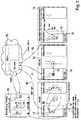
- FIG. 2shows another embodiment using any desired MCAD system 11 , an ECAD system 12 , and any desired software environment ( 13 ) as authoring systems. Communication between the authoring systems 11 , 12 , 13 is configured via web services in a cloud-based data memory.
- the data structure and development status information stored in the data memorycan also be accessed outside the authoring systems 11 , 12 , 13 , which can be initiated both from the authoring systems 11 , 12 , 13 or directly from the browser.
- the decentralized data memorymakes the arrangement location-independent; it can consequently be established across any desired locations.
- the structureshows how embodiments, features, and/or attributes from each of the authoring systems 11 , 12 , 13 can be linked, mutually communicated, and made available via a data memory.
- a plug-in 14 in the MCAD system 11is used to link CAD objects, such as parts and/or assemblies, to the common mechatronics product structure.
- the structure, the status information and featurescan also be viewed and modified outside the authoring systems 11 , 12 , 13 and the plug-ins. This is done here using a web browser 20 .
- the web browser 20is also used to model the mechatronics structure which is then available for linking in the authoring systems 11 , 12 , 13 via the plug-ins.
- the browser applicationcan both be started directly in the browser or via the plug-ins and includes all features of modern web UIs, currently based on HTML5 standards.
- the server applicationcan administer and store one or several mechatronics projects with their structures, features, and the mechatronics status information. It can also happen that the plug-ins buffer status information in the authoring systems and then use it for fast status reconciliation ( 21 ).
- the plug-ins 14 , 15 , 16can be represented in the authoring systems 11 , 12 , 13 , and the status information of all disciplines can be represented in the web application 20 . This can be done, for example, visually, such as in the form of traffic lights, linking icons, text, or the like.
- a structurecan be created in the browser extension and represented within the extension of the respective discipline.
- An elementcan also be assigned to the respective technical discipline within the extension. This can for example be a 3D component in the mechanics CAD, a circuit diagram page or a circuit diagram element from the electrical CAD, or a function block from software development. After successful linking, the communication functionality of the extension can be communicated with other disciplines.
- This communicationcan be reproduced within the browser application.
- all changesare documented in a so-called “activity stream”.
- the status of each disciplinecan be changed by the respective extension.
- the statuscan also be viewed from the respective other disciplines. This means that, for example, a mechanics developer can see if a requirement has already been implemented by electrical engineering.
- the principles underlying this inventionare not just suitable for developing mechatronics assemblies; they are also generally suitable for communication, cooperation, and requirements management within a discipline, e.g. mechanical development. Several designers are given the chance to communicate along an assembly, such that multiple designers can influence the development process in real time via the respective authoring systems.
Landscapes
- Engineering & Computer Science (AREA)
- Physics & Mathematics (AREA)
- Theoretical Computer Science (AREA)
- Computer Hardware Design (AREA)
- Evolutionary Computation (AREA)
- Geometry (AREA)
- General Engineering & Computer Science (AREA)
- General Physics & Mathematics (AREA)
- Stored Programmes (AREA)
- Architecture (AREA)
- Software Systems (AREA)
- Management, Administration, Business Operations System, And Electronic Commerce (AREA)
Abstract
Description
Claims (10)
Applications Claiming Priority (4)
| Application Number | Priority Date | Filing Date | Title |
|---|---|---|---|
| DE102015119414.7 | 2015-11-11 | ||
| DE102015119414 | 2015-11-11 | ||
| DE102015119414.7ADE102015119414A1 (en) | 2015-11-11 | 2015-11-11 | Method for developing an assembly having at least one mechatronic component, and a corresponding arrangement |
| PCT/DE2016/100435WO2017080543A1 (en) | 2015-11-11 | 2016-09-19 | Method for developing an assembly which has at least one mechatronic component, and a corresponding arrangement |
Publications (2)
| Publication Number | Publication Date |
|---|---|
| US20180300430A1 US20180300430A1 (en) | 2018-10-18 |
| US10810328B2true US10810328B2 (en) | 2020-10-20 |
Family
ID=57132941
Family Applications (1)
| Application Number | Title | Priority Date | Filing Date |
|---|---|---|---|
| US15/767,410Active2037-08-14US10810328B2 (en) | 2015-11-11 | 2016-09-19 | Method for developing an assembly which has at least one mechatronic component, and a corresponding arrangement |
Country Status (7)
| Country | Link |
|---|---|
| US (1) | US10810328B2 (en) |
| EP (1) | EP3374891B8 (en) |
| JP (1) | JP6674026B2 (en) |
| KR (1) | KR102125636B1 (en) |
| CN (1) | CN108351911B (en) |
| DE (1) | DE102015119414A1 (en) |
| WO (1) | WO2017080543A1 (en) |
Citations (17)
| Publication number | Priority date | Publication date | Assignee | Title |
|---|---|---|---|---|
| JPH09138823A (en) | 1995-09-11 | 1997-05-27 | Hitachi Ltd | Design / development progress management method and system, and design / development project management method and system |
| US6721614B2 (en)* | 2001-05-21 | 2004-04-13 | International Business Machines Corporation | Multi-discipline universal CAD library |
| US20050183081A1 (en)* | 2001-10-31 | 2005-08-18 | Gemplus | Installation of a compiled program, particularly in a chip card |
| US7266476B2 (en)* | 1999-09-30 | 2007-09-04 | Rockwell Automation Technologies, Inc. | Simulation method and apparatus for use in enterprise controls |
| US7467671B2 (en)* | 2003-11-28 | 2008-12-23 | Shell Oil Company | Drill bit with protection member |
| US7503032B2 (en)* | 2001-06-15 | 2009-03-10 | International Business Machines Corporation | Method and framework for model specification, consistency checking and coordination of business processes |
| US7536607B2 (en)* | 2005-02-25 | 2009-05-19 | Microsoft Corporation | Task sequence integration and execution mechanism with automated global condition checking and compensation |
| US20090192857A1 (en) | 2008-01-25 | 2009-07-30 | Morse Richard A | Product Lifecycle Management Method and Apparatus |
| US7703071B2 (en)* | 2006-04-13 | 2010-04-20 | International Business Machines Corporation | Method for modeling business transformation |
| JP2011107962A (en) | 2009-11-17 | 2011-06-02 | Canon Inc | Simulation device and simulation method |
| DE102010043405A1 (en) | 2010-08-25 | 2012-03-01 | Siemens Aktiengesellschaft | Method and system for the planning of mechatronic systems with mechatronic units |
| US8145518B2 (en)* | 2008-10-01 | 2012-03-27 | International Business Machines Corporation | System and method for finding business transformation opportunities by analyzing series of heat maps by dimension |
| US8175911B2 (en)* | 2008-10-01 | 2012-05-08 | International Business Machines Corporation | System and method for inferring and visualizing correlations of different business aspects for business transformation |
| US8738410B2 (en)* | 2007-05-31 | 2014-05-27 | The Boeing Company | Methods and systems for managing electronic work instructions for manufacture of product |
| US9250897B2 (en)* | 2004-09-30 | 2016-02-02 | Rockwell Automation Technologies, Inc. | Systems and methods that facilitate management of add-on instruction generation, selection, and/or monitoring during execution |
| US9720393B2 (en)* | 2012-08-31 | 2017-08-01 | P.C. Automax Inc. | Automation system and method of manufacturing product using automated equipment |
| US9904268B2 (en)* | 2002-10-22 | 2018-02-27 | Fisher-Rosemount Systems, Inc. | Updating and utilizing dynamic process simulation in an operating process environment |
Family Cites Families (9)
| Publication number | Priority date | Publication date | Assignee | Title |
|---|---|---|---|---|
| JP3447522B2 (en)* | 1997-08-28 | 2003-09-16 | シャープ株式会社 | Method and apparatus for creating component placement constraint on board |
| US20070061154A1 (en)* | 2003-11-14 | 2007-03-15 | Koninklijke Philips Electronics N.V. | Product data exchange |
| JP5030737B2 (en)* | 2007-11-08 | 2012-09-19 | 株式会社日立製作所 | 3D CAD system |
| CN101846994B (en)* | 2009-11-16 | 2012-11-21 | 王仁辉 | Assembled electric equipment of high-performance magnesium-alloy continuous casting production line |
| CN201869225U (en)* | 2010-10-11 | 2011-06-15 | 胡一鸣 | Port identification system with collaborative design based on WAP and WEB |
| CN102479357B (en)* | 2010-11-30 | 2015-12-16 | 大族激光科技产业集团股份有限公司 | A kind of product development system |
| CN103279831B (en)* | 2013-06-27 | 2016-01-20 | 李岩 | For the management system implementation method of evaluation software test mass and development ability |
| CN104200009B (en)* | 2014-08-11 | 2017-03-29 | 华东师范大学 | A kind of visualization interactive simulation method of multilayer circuit structure high-density wiring |
| CN104239613B (en)* | 2014-08-29 | 2017-11-14 | 北京动力机械研究所 | engine collaborative design integrated application system |
- 2015
- 2015-11-11DEDE102015119414.7Apatent/DE102015119414A1/ennot_activeCeased
- 2016
- 2016-09-19WOPCT/DE2016/100435patent/WO2017080543A1/ennot_activeCeased
- 2016-09-19USUS15/767,410patent/US10810328B2/enactiveActive
- 2016-09-19JPJP2018525405Apatent/JP6674026B2/enactiveActive
- 2016-09-19CNCN201680065894.XApatent/CN108351911B/enactiveActive
- 2016-09-19EPEP16781282.5Apatent/EP3374891B8/enactiveActive
- 2016-09-19KRKR1020187016453Apatent/KR102125636B1/enactiveActive
Patent Citations (17)
| Publication number | Priority date | Publication date | Assignee | Title |
|---|---|---|---|---|
| JPH09138823A (en) | 1995-09-11 | 1997-05-27 | Hitachi Ltd | Design / development progress management method and system, and design / development project management method and system |
| US7266476B2 (en)* | 1999-09-30 | 2007-09-04 | Rockwell Automation Technologies, Inc. | Simulation method and apparatus for use in enterprise controls |
| US6721614B2 (en)* | 2001-05-21 | 2004-04-13 | International Business Machines Corporation | Multi-discipline universal CAD library |
| US7503032B2 (en)* | 2001-06-15 | 2009-03-10 | International Business Machines Corporation | Method and framework for model specification, consistency checking and coordination of business processes |
| US20050183081A1 (en)* | 2001-10-31 | 2005-08-18 | Gemplus | Installation of a compiled program, particularly in a chip card |
| US9904268B2 (en)* | 2002-10-22 | 2018-02-27 | Fisher-Rosemount Systems, Inc. | Updating and utilizing dynamic process simulation in an operating process environment |
| US7467671B2 (en)* | 2003-11-28 | 2008-12-23 | Shell Oil Company | Drill bit with protection member |
| US9250897B2 (en)* | 2004-09-30 | 2016-02-02 | Rockwell Automation Technologies, Inc. | Systems and methods that facilitate management of add-on instruction generation, selection, and/or monitoring during execution |
| US7536607B2 (en)* | 2005-02-25 | 2009-05-19 | Microsoft Corporation | Task sequence integration and execution mechanism with automated global condition checking and compensation |
| US7703071B2 (en)* | 2006-04-13 | 2010-04-20 | International Business Machines Corporation | Method for modeling business transformation |
| US8738410B2 (en)* | 2007-05-31 | 2014-05-27 | The Boeing Company | Methods and systems for managing electronic work instructions for manufacture of product |
| US20090192857A1 (en) | 2008-01-25 | 2009-07-30 | Morse Richard A | Product Lifecycle Management Method and Apparatus |
| US8145518B2 (en)* | 2008-10-01 | 2012-03-27 | International Business Machines Corporation | System and method for finding business transformation opportunities by analyzing series of heat maps by dimension |
| US8175911B2 (en)* | 2008-10-01 | 2012-05-08 | International Business Machines Corporation | System and method for inferring and visualizing correlations of different business aspects for business transformation |
| JP2011107962A (en) | 2009-11-17 | 2011-06-02 | Canon Inc | Simulation device and simulation method |
| DE102010043405A1 (en) | 2010-08-25 | 2012-03-01 | Siemens Aktiengesellschaft | Method and system for the planning of mechatronic systems with mechatronic units |
| US9720393B2 (en)* | 2012-08-31 | 2017-08-01 | P.C. Automax Inc. | Automation system and method of manufacturing product using automated equipment |
Non-Patent Citations (2)
| Title |
|---|
| International Search Report (in English and German) and Written Opinion (in German) issued in PCT/DE2016/100435, dated Jan. 3, 2017; ISA/EP. |
| Japanese Office Action (w/English translation) dated Jun. 4, 2019 in corresponding Japanese Application No. 2018-525405. |
Also Published As
| Publication number | Publication date |
|---|---|
| CN108351911A (en) | 2018-07-31 |
| KR102125636B1 (en) | 2020-06-23 |
| WO2017080543A1 (en) | 2017-05-18 |
| JP2019502194A (en) | 2019-01-24 |
| KR20180102066A (en) | 2018-09-14 |
| EP3374891B8 (en) | 2021-09-08 |
| US20180300430A1 (en) | 2018-10-18 |
| EP3374891B1 (en) | 2021-07-28 |
| DE102015119414A1 (en) | 2017-05-11 |
| EP3374891A1 (en) | 2018-09-19 |
| JP6674026B2 (en) | 2020-04-01 |
| CN108351911B (en) | 2021-08-31 |
Similar Documents
| Publication | Publication Date | Title |
|---|---|---|
| Oti et al. | A framework for the utilization of Building Management System data in building information models for building design and operation | |
| Nakagawa et al. | Continuous systems and software engineering for industry 4.0: A disruptive view | |
| CN102193781A (en) | Integrated design application | |
| US10360188B2 (en) | Dynamic property data integration framework | |
| Hibino et al. | Efficient manufacturing system implementation based on combination between real and virtual factory | |
| CN107533329B (en) | Method and System for Interdisciplinary Data Validation Check in Multidisciplinary Engineering System | |
| Son et al. | Collaborative design environment between ECAD and MCAD engineers in high-tech products development | |
| CN110096377A (en) | A kind of implementation method of customized software publication | |
| CN113919030A (en) | BIM and Web 3D-based transformer substation three-dimensional model design intersection method | |
| US10810328B2 (en) | Method for developing an assembly which has at least one mechatronic component, and a corresponding arrangement | |
| Hammers et al. | Governing the process chain of product development with an enhanced Quality Gate approach | |
| Lavrischeva et al. | General disciplines and tools for e-learning software engineering | |
| Sporer et al. | Incorporation of model-based system and software development environments | |
| Loo et al. | UML extension for defining the interaction variants of design patterns | |
| Bezdeka et al. | Sequence chart studio | |
| KR101606820B1 (en) | Work system developing device and work system providing server | |
| Leite et al. | Grand challenges in information modeling for the architecture, engineering, construction, and facility management industries | |
| Hauan | Supporting Agile Processes within the Norwegian Infrastructure Industry-Integrating BIM-software with task and process management tools | |
| US10394688B2 (en) | Method for detecting computer module testability problems | |
| Himmler | Openness requirements for next generation hardware-in-the-loop testing systems | |
| Corradini et al. | Supporting multi-layer modeling in BPMN collaborations | |
| CN112860339B (en) | Application construction method and device, computer readable storage medium and electronic equipment | |
| Tomić et al. | DATA SYNCHRONISATION AND COST REDUCTION USING API IN CUSTOMER RELATIONSHIP MANAGEMENT. | |
| Niederbrucker et al. | Clouds Ahead–The Transformation of Vehicle Development and Data Management Processes | |
| Dugerdil | Architecting mobile enterprise app: a modeling approach to adapt enterprise applications to the mobile |
Legal Events
| Date | Code | Title | Description |
|---|---|---|---|
| FEPP | Fee payment procedure | Free format text:ENTITY STATUS SET TO UNDISCOUNTED (ORIGINAL EVENT CODE: BIG.); ENTITY STATUS OF PATENT OWNER: LARGE ENTITY | |
| AS | Assignment | Owner name:EPLAN SOFTWARE & SERVICE GMBH & CO. KG, GERMANY Free format text:ASSIGNMENT OF ASSIGNORS INTEREST;ASSIGNORS:LISSE, ROLF;WULFF, GERHARD;PAULFEUERBORN, ARND;SIGNING DATES FROM 20180417 TO 20180425;REEL/FRAME:045803/0940 Owner name:CIDEON SOFTWARE & SERVICES GMBH & CO. KG, GERMANY Free format text:ASSIGNMENT OF ASSIGNORS INTEREST;ASSIGNORS:LISSE, ROLF;WULFF, GERHARD;PAULFEUERBORN, ARND;SIGNING DATES FROM 20180417 TO 20180425;REEL/FRAME:045803/0940 | |
| STPP | Information on status: patent application and granting procedure in general | Free format text:DOCKETED NEW CASE - READY FOR EXAMINATION | |
| STPP | Information on status: patent application and granting procedure in general | Free format text:NON FINAL ACTION MAILED | |
| STPP | Information on status: patent application and granting procedure in general | Free format text:NOTICE OF ALLOWANCE MAILED -- APPLICATION RECEIVED IN OFFICE OF PUBLICATIONS | |
| STPP | Information on status: patent application and granting procedure in general | Free format text:PUBLICATIONS -- ISSUE FEE PAYMENT RECEIVED | |
| STCF | Information on status: patent grant | Free format text:PATENTED CASE | |
| MAFP | Maintenance fee payment | Free format text:PAYMENT OF MAINTENANCE FEE, 4TH YEAR, LARGE ENTITY (ORIGINAL EVENT CODE: M1551); ENTITY STATUS OF PATENT OWNER: LARGE ENTITY Year of fee payment:4 |