US10809345B2 - Torque limiter devices, systems and methods and solar trackers incorporating torque limiters - Google Patents
Torque limiter devices, systems and methods and solar trackers incorporating torque limitersDownload PDFInfo
- Publication number
- US10809345B2 US10809345B2US16/055,663US201816055663AUS10809345B2US 10809345 B2US10809345 B2US 10809345B2US 201816055663 AUS201816055663 AUS 201816055663AUS 10809345 B2US10809345 B2US 10809345B2
- Authority
- US
- United States
- Prior art keywords
- torsion
- solar tracker
- torque
- solar
- assembly
- Prior art date
- Legal status (The legal status is an assumption and is not a legal conclusion. Google has not performed a legal analysis and makes no representation as to the accuracy of the status listed.)
- Active
Links
Images


Classifications
- G—PHYSICS
- G01—MEASURING; TESTING
- G01S—RADIO DIRECTION-FINDING; RADIO NAVIGATION; DETERMINING DISTANCE OR VELOCITY BY USE OF RADIO WAVES; LOCATING OR PRESENCE-DETECTING BY USE OF THE REFLECTION OR RERADIATION OF RADIO WAVES; ANALOGOUS ARRANGEMENTS USING OTHER WAVES
- G01S3/00—Direction-finders for determining the direction from which infrasonic, sonic, ultrasonic, or electromagnetic waves, or particle emission, not having a directional significance, are being received
- G01S3/78—Direction-finders for determining the direction from which infrasonic, sonic, ultrasonic, or electromagnetic waves, or particle emission, not having a directional significance, are being received using electromagnetic waves other than radio waves
- G01S3/782—Systems for determining direction or deviation from predetermined direction
- G01S3/785—Systems for determining direction or deviation from predetermined direction using adjustment of orientation of directivity characteristics of a detector or detector system to give a desired condition of signal derived from that detector or detector system
- G01S3/786—Systems for determining direction or deviation from predetermined direction using adjustment of orientation of directivity characteristics of a detector or detector system to give a desired condition of signal derived from that detector or detector system the desired condition being maintained automatically
- G01S3/7861—Solar tracking systems
- H—ELECTRICITY
- H02—GENERATION; CONVERSION OR DISTRIBUTION OF ELECTRIC POWER
- H02S—GENERATION OF ELECTRIC POWER BY CONVERSION OF INFRARED RADIATION, VISIBLE LIGHT OR ULTRAVIOLET LIGHT, e.g. USING PHOTOVOLTAIC [PV] MODULES
- H02S20/00—Supporting structures for PV modules
- H02S20/30—Supporting structures being movable or adjustable, e.g. for angle adjustment
- F—MECHANICAL ENGINEERING; LIGHTING; HEATING; WEAPONS; BLASTING
- F16—ENGINEERING ELEMENTS AND UNITS; GENERAL MEASURES FOR PRODUCING AND MAINTAINING EFFECTIVE FUNCTIONING OF MACHINES OR INSTALLATIONS; THERMAL INSULATION IN GENERAL
- F16D—COUPLINGS FOR TRANSMITTING ROTATION; CLUTCHES; BRAKES
- F16D43/00—Automatic clutches
- F16D43/02—Automatic clutches actuated entirely mechanically
- F16D43/20—Automatic clutches actuated entirely mechanically controlled by torque, e.g. overload-release clutches, slip-clutches with means by which torque varies the clutching pressure
- F16D43/202—Automatic clutches actuated entirely mechanically controlled by torque, e.g. overload-release clutches, slip-clutches with means by which torque varies the clutching pressure of the ratchet type
- F16D43/2022—Automatic clutches actuated entirely mechanically controlled by torque, e.g. overload-release clutches, slip-clutches with means by which torque varies the clutching pressure of the ratchet type with at least one part moving axially between engagement and disengagement
- F16D43/2024—Automatic clutches actuated entirely mechanically controlled by torque, e.g. overload-release clutches, slip-clutches with means by which torque varies the clutching pressure of the ratchet type with at least one part moving axially between engagement and disengagement the axially moving part being coaxial with the rotation, e.g. a gear with face teeth
- F—MECHANICAL ENGINEERING; LIGHTING; HEATING; WEAPONS; BLASTING
- F16—ENGINEERING ELEMENTS AND UNITS; GENERAL MEASURES FOR PRODUCING AND MAINTAINING EFFECTIVE FUNCTIONING OF MACHINES OR INSTALLATIONS; THERMAL INSULATION IN GENERAL
- F16D—COUPLINGS FOR TRANSMITTING ROTATION; CLUTCHES; BRAKES
- F16D43/00—Automatic clutches
- F16D43/02—Automatic clutches actuated entirely mechanically
- F16D43/20—Automatic clutches actuated entirely mechanically controlled by torque, e.g. overload-release clutches, slip-clutches with means by which torque varies the clutching pressure
- F16D43/21—Automatic clutches actuated entirely mechanically controlled by torque, e.g. overload-release clutches, slip-clutches with means by which torque varies the clutching pressure with friction members
- F16D43/213—Automatic clutches actuated entirely mechanically controlled by torque, e.g. overload-release clutches, slip-clutches with means by which torque varies the clutching pressure with friction members with axially applied torque-limiting friction surfaces
- F16D43/215—Automatic clutches actuated entirely mechanically controlled by torque, e.g. overload-release clutches, slip-clutches with means by which torque varies the clutching pressure with friction members with axially applied torque-limiting friction surfaces with flat friction surfaces, e.g. discs
- F—MECHANICAL ENGINEERING; LIGHTING; HEATING; WEAPONS; BLASTING
- F24—HEATING; RANGES; VENTILATING
- F24S—SOLAR HEAT COLLECTORS; SOLAR HEAT SYSTEMS
- F24S30/00—Arrangements for moving or orienting solar heat collector modules
- F24S30/40—Arrangements for moving or orienting solar heat collector modules for rotary movement
- F24S30/42—Arrangements for moving or orienting solar heat collector modules for rotary movement with only one rotation axis
- F24S30/425—Horizontal axis
- F—MECHANICAL ENGINEERING; LIGHTING; HEATING; WEAPONS; BLASTING
- F24—HEATING; RANGES; VENTILATING
- F24S—SOLAR HEAT COLLECTORS; SOLAR HEAT SYSTEMS
- F24S40/00—Safety or protection arrangements of solar heat collectors; Preventing malfunction of solar heat collectors
- H—ELECTRICITY
- H02—GENERATION; CONVERSION OR DISTRIBUTION OF ELECTRIC POWER
- H02S—GENERATION OF ELECTRIC POWER BY CONVERSION OF INFRARED RADIATION, VISIBLE LIGHT OR ULTRAVIOLET LIGHT, e.g. USING PHOTOVOLTAIC [PV] MODULES
- H02S30/00—Structural details of PV modules other than those related to light conversion
- F—MECHANICAL ENGINEERING; LIGHTING; HEATING; WEAPONS; BLASTING
- F24—HEATING; RANGES; VENTILATING
- F24S—SOLAR HEAT COLLECTORS; SOLAR HEAT SYSTEMS
- F24S30/00—Arrangements for moving or orienting solar heat collector modules
- F24S2030/10—Special components
- F24S2030/11—Driving means
- F24S2030/115—Linear actuators, e.g. pneumatic cylinders
- F—MECHANICAL ENGINEERING; LIGHTING; HEATING; WEAPONS; BLASTING
- F24—HEATING; RANGES; VENTILATING
- F24S—SOLAR HEAT COLLECTORS; SOLAR HEAT SYSTEMS
- F24S30/00—Arrangements for moving or orienting solar heat collector modules
- F24S2030/10—Special components
- F24S2030/13—Transmissions
- F24S2030/134—Transmissions in the form of gearings or rack-and-pinion transmissions
- F—MECHANICAL ENGINEERING; LIGHTING; HEATING; WEAPONS; BLASTING
- F24—HEATING; RANGES; VENTILATING
- F24S—SOLAR HEAT COLLECTORS; SOLAR HEAT SYSTEMS
- F24S30/00—Arrangements for moving or orienting solar heat collector modules
- F24S2030/10—Special components
- F24S2030/13—Transmissions
- F24S2030/136—Transmissions for moving several solar collectors by common transmission elements
- F—MECHANICAL ENGINEERING; LIGHTING; HEATING; WEAPONS; BLASTING
- F24—HEATING; RANGES; VENTILATING
- F24S—SOLAR HEAT COLLECTORS; SOLAR HEAT SYSTEMS
- F24S30/00—Arrangements for moving or orienting solar heat collector modules
- F24S2030/10—Special components
- F24S2030/15—Bearings
- Y—GENERAL TAGGING OF NEW TECHNOLOGICAL DEVELOPMENTS; GENERAL TAGGING OF CROSS-SECTIONAL TECHNOLOGIES SPANNING OVER SEVERAL SECTIONS OF THE IPC; TECHNICAL SUBJECTS COVERED BY FORMER USPC CROSS-REFERENCE ART COLLECTIONS [XRACs] AND DIGESTS
- Y02—TECHNOLOGIES OR APPLICATIONS FOR MITIGATION OR ADAPTATION AGAINST CLIMATE CHANGE
- Y02E—REDUCTION OF GREENHOUSE GAS [GHG] EMISSIONS, RELATED TO ENERGY GENERATION, TRANSMISSION OR DISTRIBUTION
- Y02E10/00—Energy generation through renewable energy sources
- Y02E10/40—Solar thermal energy, e.g. solar towers
- Y02E10/47—Mountings or tracking
- Y—GENERAL TAGGING OF NEW TECHNOLOGICAL DEVELOPMENTS; GENERAL TAGGING OF CROSS-SECTIONAL TECHNOLOGIES SPANNING OVER SEVERAL SECTIONS OF THE IPC; TECHNICAL SUBJECTS COVERED BY FORMER USPC CROSS-REFERENCE ART COLLECTIONS [XRACs] AND DIGESTS
- Y02—TECHNOLOGIES OR APPLICATIONS FOR MITIGATION OR ADAPTATION AGAINST CLIMATE CHANGE
- Y02E—REDUCTION OF GREENHOUSE GAS [GHG] EMISSIONS, RELATED TO ENERGY GENERATION, TRANSMISSION OR DISTRIBUTION
- Y02E10/00—Energy generation through renewable energy sources
- Y02E10/50—Photovoltaic [PV] energy
Definitions
- the present disclosurerelates to torsion limiter devices, systems, and methods.
- the present disclosurefurther relates to torque release mechanisms in mechanical positioning systems.
- the present disclosurefurther relates to torque limiting and slip clutch assemblies.
- the hinge momenttypically is resisted at a single point.
- the resulting torsional forces applied to relatively long torsion tubes or other beam configurationsmay be large and tend to interact with the torsional flexibility of the tracker structure.
- Counteracting the high hinge moment forces at a single point in the structurerequires sufficiently strong torsional members to resist both the high combined torque and the beam loads of the system without excess flexibility.
- the hinge moment forcesmay present as a static force or sometimes dynamic force known as torsional divergence.
- the structural system of the trackeris flexible in its design, and is torsionally restrained at a single point, torsional divergence and other dynamic forces may occur that have the potential to substantially increase the loading on the structure. It is therefore structurally advantageous to minimize the flexibility of the tracker structure to reduce or eliminate the wind interactions that may cause these dynamic forces.
- Exemplary embodiments of the present disclosurealleviate to a great extent the disadvantages of known mechanical systems such as solar trackers by incorporating a torsion limiter, which may in some instances be a torque limiting clutch, at the output of a primary gearbox, prior to the engagement of a secondary gear rack in each tracker row. In essence, this places a pre-set torque release mechanism between the torsion stressed components and the drive in each individually motorized or linked tracker row of a tracker system.
- Exemplary embodiments of this disclosureadvantageously minimize the wind induced torsion forces on the tracker array in order to materially reduce the structural requirements of the tracking system. Materially reducing structure may result in a considerable reduction in the cost of the tracker system.
- Exemplary embodiments of a torsion limiteract as a torsional force relief valve that minimizes the hinge moments and eliminates any significant dynamic forces that may be induced by the wind on mechanical systems such as PV tracking structures.
- An important functionis to relieve the torsion during high wind events and allow each individual tracker row to move to a different position until either the array moves to a position in which the torsion force is no longer able to overcome the preset torsion release force, or the array is moved by the torsional force to the extreme angles of rotation and is then restrained at multiple points on the structure. Incorporating multiple stops along the array at the extreme rotation positions minimizes the torsion force in any one section of the torsional resisting structural component or components.
- the torsion limitermay also act as an overload relief from the input force of the drive motor if the array cannot move due to an obstruction such as an unbalanced heavy snow load, snow drift, or sand dune, or if one or more of the linked gear sets are at an extreme limit stop condition. In this condition the torsion limiting clutch will de-couple the input driving forces from the output forces if the obstruction resistance is greater than the torsion limiting threshold.
- the forces that will be released by the torsion limiterwill be both the hinge moment forces induced externally on the array, and also from the input driving mechanism, when the input driving forces required to move the array are above the torsion limiter threshold.
- Exemplary embodiments of a solar tracker assemblycomprise a support column, a torsion beam connected to the support column, a mounting mechanism attached to the torsion beam, a drive system connected to the torsion beam, and a torsion limiter connected to the drive system.
- the solar tracker assemblymay include a plurality of support columns and further comprise a stop at each support column.
- the torsion beammay be configured with a balanced center of gravity such that it rotates about the balanced center of gravity.
- the torsion limiterWhen an external force such as the wind causes a level of torsion in the system to exceed a pre-set limit, the torsion limiter then facilitates rotational movement of the solar tracker assembly in the direction of the torsion, thereby allowing the external force to rotate the assembly about a pivot axis extending through the torsion beam.
- the torsion limiterde-couples excess torsion such that the external force is released by allowing the array to move to a second rotational position.
- the movement in the direction of the torsionmay comprise movement of the solar tracker assembly from a first rotational position to at least one second rotational position.
- the solar trackermoves to an extreme rotational position stop position.
- the maximum rotational position mechanical stopis at a maximum angle of rotation and is then resisted at multiple points in the tracking structure so that the main torsional resisting structural member is ultimately supported rotationally at multiple points, effectively limiting the torsion in the torsion beam structure.
- the movement in the direction of the torsionmay comprise movement of the solar tracker assembly from a first rotational position to a second or multiple rotational positions.
- the solar tracker assemblyis constrained in its maximum rotational positions at multiple distributed locations along a torsional resisting structure of the solar tracker assembly.
- the torsion limiterlimits the hinge moment about the pivot axis extending through the torsion beam when the tracker is not at the extreme positions by allowing the tracker to rotate to release torsional force and then the multiple stops at the extreme positions ultimately limit the torsion in any one section of the torsion resisting structural member when the system cannot rotate any further.
- the drive system of the solar tracker assemblycomprises a gear assembly including at least one gear wheel.
- the gear assemblyincludes a one-way gearbox and the torsion limiter is a torsion limiting clutch.
- the torsion limitermay also be a slip clutch in some embodiments.
- the gear assemblyincludes a friction coupling engaging the gear wheel and the torsion limiter is located at the friction coupling.
- the torsion limitermay be located at the output of a first gear stage of the gear assembly.
- the solar tracker assemblyis a push/pull linked tracker and the torsion limiter is a linear slip device or linear clutch linkage.
- the solar tracker assemblymay include a hydraulic system and the torsion limiter may be in the form of a pressure relief valve in the hydraulic system.
- the solar tracker assemblymay further comprise a damper incorporated at or near the gear rack to control the release of torsional force and slow the motion of the solar tracker assembly.
- Exemplary embodimentsinclude methods of aligning a solar array comprising a plurality of rows of solar trackers, providing a torsion limiter individually connected to each row of solar trackers, where one or more of the solar trackers encounter a mechanical rotational limit which causes the level of torsion induced by the driveline in the at least one row of solar trackers to exceed the torsion limit threshold, whereby the torsion limiter allows the mechanically limited at least one row not to rotate while simultaneously driving the rotation of the other multiple rows of solar trackers.
- the plurality of rows of solar trackersincludes multiple rows of linked solar trackers.
- the mechanical limit condition on at least one row of solar trackers of the multiple rows of solar trackerscreates a level of torsion in the tracker that exceeds a pre-set threshold.
- the at least one mechanically limited rowdoes not rotate while the other multiple rows of solar trackers rotate and reach their maximum mechanical limit position until all of the plurality of rows of solar trackers are no longer rotating. As each row reaches its maximum mechanical limit position, each tracker row stops rotational movement while the other multiple rows of solar trackers rotate and reach their maximum limit positions. When all the tracker rows reach their mechanical limits, they are all in alignment.
- the same mechanism that limits and releases the driving torque at a safe thresholdis also advantageous if one or more tracker rows are obstructed from external environmental conditions such as a snow drift, sand dune or other impediment.
- the torsion limitermay protect the tracked array from damage by the obstruction while also allowing the tracker to rotate in a limited motion until the obstruction is cleared.
- the movement in the direction of the torsioncomprises movement of at least one row of solar trackers from a first rotational position to at least one second rotational position.
- the movement in the direction of the torsionmay comprise movement of at least one row of solar trackers from a first rotational position to multiple rotational positions.
- the at least one row of solar trackershits multiple mechanical constraints in the multiple rotational positions or maximum limit positions.
- Each row of solar trackersmay include a plurality of support columns and a stop at each support column.
- Exemplary embodimentsfurther comprise incorporating a damper near or at the torsion limiter to control the release of torsional force and slow the motion of the solar tracker assembly.
- Exemplary embodiments of a singular motorized solar tracker assemblycomprise a support column, one or more torsion beams connected to the support column, a solar module mounting system attached to the one or more torsion beams, a drive system connected to the one or more torsion beams, and a motor brake.
- the drive systemcomprises a bi-directional gearbox having an input and an output, and the motor brake is located at the input of the bi-directional gearbox.
- a gear drive systemcomprises a gear assembly including a torque-limiting clutch and at least one worm gear wheel.
- the gear assemblymay or may not be contained in a gearbox. When a level of torque on the gear exceeds a preset level the clutch slips.
- the gear assemblymay include two taper sections engaging the worm gear wheel.
- the torque limiting clutchis located at the two taper sections.
- the clutchmay be adjustable via a nut that varies the spring tension at the taper sections. This slip clutch may take alternate forms in exemplary embodiments and in other forms as necessary for different types of gear-driven mechanical systems.
- a solar tracker assemblycomprises at least one support column, a torsion beam connected to the support column, with a pivot axis extending through the torsion beam, a mounting mechanism attached to the torsion beam, one or more solar modules mounted to the mounting mechanism, and a gearbox assembly containing a torque limiting clutch and at least one worm gear wheel. When a level of torque on the gearbox exceeds a preset threshold, the clutch slips.
- Exemplary embodiments of a gear-driven mechanical systemcomprise at least one gear-driven mechanical unit including at least one gear rack and a gear drive system engaging with the gear rack.
- the gear drive systemcomprises a gear assembly including at least one gear wheel, and a torque-limiting clutch located at an output of the gear assembly and prior to a location where the gear drive system engages the gear rack. When a level of torque on the gear assembly exceeds a preset level the clutch slips, releasing the torque on the gear-driven mechanical unit.
- the gear assemblyincludes at least one taper section engaging the gear wheel and the torque limiting clutch is located at the taper section.
- the clutchmay be adjustable via a nut that varies the spring tension at the taper section.
- the gear-driven mechanical unitis rotatable.
- the gear-driven mechanical unitrotates to a hard stop position at its maximum angle of rotation.
- Exemplary embodiments of a gear-driven mechanical systemcomprise at least one gear-driven mechanical unit rotatable about a rotational axis and a gear drive system.
- the gear-driven mechanical unitincludes at least one gear rack and the gear drive system engages with the gear rack.
- the gear drive systemcomprises a gear assembly including at least one gear wheel and a torque limiting clutch located at an output of the gear assembly. When a level of torque on the gear assembly exceeds a pre-set level, the clutch slips, releasing the torque on the gear-driven mechanical unit and limiting a hinge moment about the rotational axis.
- the torque limiting clutchis located at the output of a first gear stage of the gear-driven mechanical unit. In exemplary embodiments, the torque limiting clutch is incorporated in the input to the gear rack of the gear-driven mechanical unit.
- the at least one gear-driven mechanical unitmay comprise a plurality of gear-driven mechanical units. In exemplary embodiments, each gear-driven mechanical unit rotates to a mechanically limited stop position at its maximum angle of rotation.
- Exemplary embodiments of a solar tracking systemcomprise at least one solar tracker assembly being held rotationally through a torque-limiting clutch.
- the solar tracker assemblyincludes at least one support column, a torsion beam connected to the support column, a module mounting means attached to the torsion beam, and at least one gear drive assembly connected to the torsion beam.
- a pivot axisextends through the torsion beam.
- the torque limiting clutchengages the gear drive assembly. When the level of externally applied torque on the gear drive assembly exceeds a preset level, the clutch slips allowing the tracking system to rotate, thereby releasing the torque on the solar tracker assembly and reducing the hinge moment about the pivot axis.
- the torque limiting clutchis located at the output of a first gear stage of the solar tracker assembly.
- the torque limiting clutchis incorporated in the gear drive assembly of the solar tracker assembly.
- the gear drive assemblymay include a main driving gear wherein the torque limiting clutch is incorporated on an output of the main driving gear.
- the solar tracker assemblyrotates to engage a mechanical stop at its maximum angle of rotation.
- the solar tracking systemmay be a linked system wherein the torque limiting clutch is incorporated between an arm connection and the torsion tube.
- the solar tracking systemmay be a push/pull linked tracker.
- the solar tracking systemis hydraulically driven, and the torque limiting clutch is a pressure relief valve.
- torsion limiterstorque-limiting clutches
- gear drive systemssolar trackers, and related torque release methods are provided.
- the disclosed devices, systems, and methodsprovide a preset torque release mechanism, thereby reducing or eliminating the hinge moments and other dynamic forces on the PV tracking structure.
- FIG. 1Ais a schematic of an exemplary embodiment of a mechanical unit in accordance with the present disclosure
- FIG. 1Bis a schematic of an exemplary embodiment of a mechanical unit in accordance with the present disclosure
- FIG. 1Cis a schematic of an exemplary embodiment of a mechanical unit in accordance with the present disclosure.
- FIG. 1Dis a schematic of an exemplary embodiment of a mechanical unit in accordance with the present disclosure.
- FIG. 2is a process flow diagram of an exemplary method of limiting torsion in accordance with the present disclosure
- FIG. 3is a perspective view of an exemplary embodiment of a solar tracker in accordance with the present disclosure
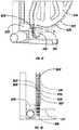
- FIG. 4is a detail cutaway view of an exemplary embodiment of a solar tracker including a torsion limiter in accordance with the present disclosure
- FIG. 5is a detail cutaway view of an exemplary embodiment of a gear-driven mechanical unit including a torsion limiter in accordance with the present disclosure
- FIG. 6is a perspective view of an exemplary embodiment of a multiple friction plate torsion limiter in accordance with the present disclosure
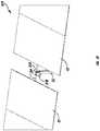
- FIG. 7Ais a perspective view of an exemplary embodiment of an individually motorized solar tracker incorporating an exemplary torsion limiter in accordance with the present disclosure
- FIG. 7Bis a perspective view of the solar tracker of FIG. 7A ;
- FIG. 8is a perspective view of an exemplary embodiment of a linked gear drive solar tracker array including an exemplary torque-limiting clutch in accordance with the present disclosure
- FIG. 9is a perspective view of an exemplary embodiment of a push/pull tracker system incorporating an exemplary embodiment of a rotary torsion limiter in accordance with the present disclosure
- FIG. 10is a perspective view of an exemplary embodiment of a push/pull linked tracker system including an exemplary embodiment of a linear slip force limiter in accordance with the present disclosure
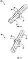
- FIG. 11is a perspective view of an exemplary embodiment of a linear slip force limiter in accordance with the present disclosure.
- FIG. 12Ais a rear perspective view an exemplary embodiment of a hydraulic ram driven solar tracker including an exemplary over pressure valve in accordance with the present disclosure
- FIG. 12Bis a side view of the solar tracker of FIG. 12A ;
- FIG. 13is a perspective view of an exemplary embodiment of a hydraulic cylinder or ram in accordance with the present disclosure
- FIG. 14is a cutaway view of an exemplary embodiment of an over pressure valve in accordance with the present disclosure.
- FIG. 15is a perspective view of an exemplary embodiment of a solar tracker gear assembly and exemplary torsion limiter in accordance with the present disclosure
- FIG. 16is a side view of an exemplary embodiment of a solar tracker gear assembly and exemplary torsion limiter in accordance with the present disclosure
- FIG. 17is a detail view of an exemplary embodiment of a solar tracker gear assembly and exemplary torsion limiter in accordance with the present disclosure
- FIG. 18is side detail view of an exemplary embodiment of a solar tracker gear assembly and exemplary torsion limiter in accordance with the present disclosure
- FIG. 19is a perspective view of an exemplary embodiment of a solar tracker including an exemplary motor brake in accordance with the present disclosure
- FIG. 20is a cut-away view of an exemplary embodiment of a motor brake in accordance with the present disclosure.
- FIG. 21is a perspective cut-away view of a DC brush motor as used in exemplary embodiments of the present disclosure.
- FIG. 22is a schematic diagram of an exemplary method of shorting out the motor armature of a brush type DC motor to create a motor brake in accordance with the present disclosure
- FIG. 23Ais a perspective view of an exemplary embodiment of a limit stop in accordance with the present disclosure.
- FIG. 23Bis a perspective view of an exemplary embodiment of the limit stop of FIG. 23A ;
- FIG. 23Cis a perspective view of the limit stop of FIG. 23A ;
- FIG. 23Dis a perspective view the limit stop of FIG. 23A at an extreme position
- FIG. 24Ais a perspective view of an exemplary embodiment of a limit stop in accordance with the present disclosure.
- FIG. 24Bis a side view of the limit stop of FIG. 24A ;
- FIG. 24Cis a cross-sectional view of the limit stop of FIG. 24A .
- Exemplary embodiments of torsion limitersmay be advantageously used in any kind of driven system that may be exposed to external forces such as high wind forces and could benefit from the ability to resist the external force at multiple points along the structure instead of just at a single point.
- Solar trackersare one example of such a system, and exemplary embodiments could be used in any kind of solar tracker, including but not limited to single-axis trackers such as horizontal, tilt and roll, and azimuth, as well as dual-axis trackers.
- Exemplary embodimentsinclude any solar tracker design that includes a torsion limiter connected between the output of the drive and the collector array where the torsion limiter releases at a pre-set level of torsion force.
- Exemplary embodimentsinclude solar trackers that are gear-driven, hydraulically driven, or driven by any other means.
- Exemplary tracker geometriesincorporate a worm-gear primary gear drive, either attached to the tracker frame directly or through a secondary stage such as a spur gear rack, D-ring chain drive, or cable system mounted to one or two column supports for the tracker.
- Exemplary solar tracker embodimentsmay incorporate a balanced array such that the torsion limiter force remains constant at any tracker rotational angle.
- Exemplary embodiments of the disclosurerelease torsion in a tracking system so the system moves out of a high torque position to a second position and stops, or if the external force is great enough, the system moves to an extreme position where torsion force can be resisted at multiple points instead of at a single point, usually the center of the system.
- an obstructionsuch as a sand dune, snow, ice, or some other external obstruction
- torque from the system's drive motoris released from the input drive by the torsion limiter.
- only the row or rows that are affected by the obstructiondo not move while the other unobstructed linked rows will continue to track.
- exemplary embodimentsadvantageously provide the benefit of releasing two different types of torque, external torsion forces from the wind and/or internal torsion forces generated by the drive when the tracking system output is obstructed.
- the wind forceinduces a hinge moment on the tracker system. If the hinge moment is greater than the holding force of the torsion limiter, the torsion limiter releases the torsion and the tracker moves to second position at which the force may be lessened because the wind gust has reduced or the hinge moment has been reduced as a result of the new rotational position. If the movement continues and the system is driven to the extreme position multiple mechanical stops, then the wind can be resisted at multiple points instead of at a single point.
- systems employing exemplary embodiments of torsion limitersreact in a natural or passive way, without the need for electronics such as a motor or active release.
- the torsion limiteris a clutch assembly which passively slips and has the opportunity to correct itself twice a day, once in the morning and once in the evening as the motor drives the system into the extreme stop positions.
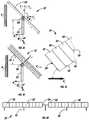
- the windacts on a tracked PV array
- the windnormally causes a hinge moment M H to occur about the rotational axis of the tracker as shown in FIGS. 1A-1D .
- the features and characteristics of an exemplary solar tracker subject to the windare designated as follows:
- exemplary torsion limiters and related gear drives and solar trackersreduce or eliminate the hinge moment on the tracker.
- FIG. 2shows an exemplary method 1000 incorporating a torsion limiter.
- a torsion limiteris any device that can limit, release, relieve, or otherwise reduce the level of torsion, torque, or other external force on a system by any means, including but not limited to, slipping, de-coupling force, releasing pressure, facilitating movement, or separating components of a system. As discussed in more detail herein, there are many design variants of torsion limiters.
- the systemmay be configured to have a pre-set limit on the level of torsion to which it can safely be exposed ( 1010 ).
- the torsion limiteracts to reduce the level of torsion on the system ( 1030 ).
- the torsion reduction actioncan be slipping ( 1040 ), releasing pressure ( 1050 ), and/or facilitating rotational movement of the system in the direction of the torsion ( 1060 ).
- the system's movement in the direction of the torsionmeans the system moves from a first position to at least one second position ( 1080 ).
- the systemmay hit a maximum position stop in the at least one second position ( 1090 ). If the movement is rotational movement, the maximum position stop may be at a maximum angle of rotation ( 1100 ).
- the movement in the direction of the torsionmay be from a first position to multiple positions ( 1110 ).
- the systemis constrained in its maximum positions at multiple distributed locations along a torsional resisting structure of the solar tracker assembly ( 1120 ).
- Gear-driven mechanical system 10may be any kind of mechanical system having one or more mechanical units and using gears to drive mechanical components for rotation, movement and/or to generate work, including but not limited to transportation systems, agricultural systems, manufacturing systems, and energy conversion and/or power generation systems.
- An exemplary gear-driven mechanical system 10comprises at least one gear-driven mechanical unit 12 that includes a gear rack 14 .
- the mechanical system 10may also include a gear drive system 16 that incorporates a torsion limiter such as a torque limiting clutch 18 . More particularly, an exemplary gear drive system 16 comprises a torque limiting clutch 18 and a gear assembly 20 including at least one gear wheel 22 .
- a motor 15may be provided to drive the gear drive system 16 , which in turn rotates a beam or tube, e.g., torsion tube 34 , directly, or drives a gear rack 14 , which in turn drives the torsion tube or other module mounting beam structure 34 .
- the gear rack 14may be a spur gear rack or D-ring chain drive, which is affixed to a rotatable tube, e.g., torsion tube 34 , of the mechanical unit 12 .
- the torque-limiting clutch 18is located at an output of the gear assembly 20 , on the first gear stage of the mechanical unit 12 , and prior to a location where the gear drive system 16 engages the gear rack 14 of the mechanical unit 12 .
- a second, third, etc. mechanical unit, similar to tracking assembly 12can be connected to drive shaft 25 with a separate and similar worm assembly. This can be repeated for several mechanical units in a gear-driven mechanical system.
- the gear wheel 22may be any kind of gear wheel and is shown, by way of example, as a worm wheel which engages worm 21 .
- the worm wheel 22may define two taper sections 26 at the center.
- the clutch 18is located at these taper sections 26 .
- the clutchmay be adjustable via a nut 44 or other equivalent mechanism that varies the spring tension on the taper 26 .
- Gearbox output shaft 43connects the gearbox 24 to the gear rack 14 .
- springs 19are provided on the output shaft 43 .
- the springscould be in the form of washers 19 such as Belleville washers.
- the washers 19are conical discs facing each other on the output shaft 43 outside the gearbox 24 .
- the washers 19act as springs that provide the pressure for the conical sections against the worm wheel 22 .
- an exemplary solar tracker 12comprises at least one support column 32 , which may be any shape and composed of any material so long as it is capable of supporting the PV modules and other components mounted thereto.
- Exemplary embodiments of a solar tracker 12include two spaced-apart support columns 32 a and 32 b .
- a torsion beam 34 or other tracker structureis connected to the support column 32 . More particularly, the torsion beam bridges the two support columns 32 a , 32 b and may be attached to the support columns by a bearing 36 and bearing housing arrangement including any suitable fasteners.
- the torsion beam 34may be any shape or configuration suitable for supporting a mounting rack or other mounting mechanism, including multiple connected beams, and in exemplary embodiments it has a circular-, square- or hexagonal-shaped cross section. In a system that has overhung weight, the overhung dead load torsion varies as the system rotates. Alternate exemplary torsion beam embodiments may be configured with a balanced center of gravity, such that the weight of the array is rotated about the balance point. This balanced system may be advantageous to incorporate into the torsion limiting design because, without any overhung weight, it will keep the torsional release force constant at all rotational positions.
- a pivot axis 40extends through the torsion beam 34 , and the torsion beam 34 may pivot or rotate about the pivot axis 40 .
- Solar modules 42may be mounted to the solar tracker 12 , either mounted on the torsion beam 34 using clamps 35 or via a module mounting bracket assembly. It should be noted that solar trackers could employ more than one torsion beam in a double- or multiple-beam torsion structure arrangement. In such embodiments, a tracker would have two or more torsion beams running along its length. A row of multiple trackers could have two or more torsion beams running along the length of the row.
- the gear drive system 16 of the solar tracker 12incorporates a torque-limiting clutch 18 on the first gear stage of the solar tracker 12 .
- Exemplary embodimentscould include a single-stage gear-driven solar tracker where the gear drive system 16 is a single-stage worm gear drive that directly rotates the solar collector array.
- the torsion limiterin the form of a clutch, could be located between the connection of the output of the worm gear drive and the solar collector array.
- Exemplary embodimentsalso include two- or multi-stage solar trackers.
- Gear assembly 20includes at least one gear wheel 22 , and in exemplary embodiments the gear wheel is a worm wheel.
- the torque limiting clutch 18is located between the connection of the output of the first stage worm gear and the second stage gear.
- the second or multiple stage gear or gearsmay be constructed of any type of bi-directional gear drive system capable of transmitting rotary force bi-directionally, including but not limited to, a spur gear, pin gear, cable drive, belt or chain drive.
- the torque-limiting clutch 18may be located at an output of the gear assembly 20 , on the output of the first gear stage of the solar tracker 12 , and prior to a location where the gear drive system 16 engages the gear rack 14 of the solar tracker 12 .
- the clutch 18may be located at two taper sections 26 of the worm wheel gear 22 .
- the two steel tapers 26engage the worm wheel gear 22 under spring tension, which may be adjustable via a nut 44 or other adjustment mechanism.
- the torque-limiting clutchmay be incorporated into a plurality of solar trackers 12 connected into an array layout comprised of one or more rows 46 of solar trackers. More particularly, multiple solar trackers 12 may be mechanically linked in a large array configuration 50 so they may operate in unison, driven by a single motor and tracker controller.
- the array configurationscould be implemented by providing a rotary drive linkage system underneath the solar tracker array.
- Another bearing system, such as a slew drivemay also be incorporated in the fixed-tilt azimuth tracking geometry if it is properly designed to withstand the load forces applied near the base of the array support.
- the arraycould have a motor at each solar collector gear drive.
- a torsion limiting featuremay be incorporated into the motorized gear drive assembly.
- the drive systemcould incorporate the linked worm-gear drive into a carousel type fixed tilt azimuth tracking array field.
- the tilted solar arrayis rotated on a large area circular bearing to track the sun.
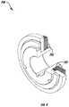
- an exemplary embodiment of a high-torsion, spring force, multiple-plate torsion limiter 718may be comprised of multiple interleaved spring loaded friction plates 715 .
- Springs 717create a friction force on the friction plates 715 causing an increase in the friction surface area of the torsion limiter 718 .
- This designis an exemplary variant of the spring loaded tapered cone torsion limiter depicted in FIGS. 4 and 5 .
- the inside diametermay be connected to one shaft and the outside diameter connected to a different shaft.
- the torsion limiter 718limits the torsion between the two shafts.
- the torsion limitercan be incorporated inside a worm gear drive unit between the gearing and the output, as shown in FIG.
- FIG. 7Bor mounted outside of the worm gear unit on the connection of the torsion tube to the worm gear unit, as illustrated in FIG. 7A .
- itcan be connected to the torsion tube on the inner diameter and the linear arm to limit torsion on the array of a linked tracking system, as in FIG. 10 .
- FIGS. 7A-12BExemplary embodiments of systems using torque-limiting clutch assemblies are shown, as solar tracker systems by way of example, in FIGS. 7A-12B .
- the torsion limiting clutchmay be at a location other than on the first gear stage of the tracker.
- an exemplary embodiment of an individually motorized gear-driven solar tracker 112may have a clutch 118 at the output of a gear assembly or incorporated inside the drive unit 116 .
- Such embodimentsare configured are configured similarly to the exemplary systems shown in FIGS. 3-4 , in which multiple trackers are driven by a single motor, and the torque-limiting clutch 18 operates in the same way, providing the same advantages.
- torsion beam 34is connected to the support column 32 , and solar modules 42 may be mounted to the tracker 112 .
- the torsion limiter or clutch 118may be located on the connection of the output of the gear drive unit 116 to the torsion tube 34 of an independently motorized gear-driven solar tracker 112 . More particularly, the clutch 118 is mechanically connected to the output of the gear assembly (within drive unit 116 ). Alternatively, the clutch may be incorporated into other stages of the gear train such as between a brake motor and a bi-directional gear drive. Additional torsion limiting clutches 118 may be provided and, in exemplary embodiments, are located between a rotary actuator 111 and the torsion beam 34 of the tracker 112 . In exemplary embodiments, the drive unit 116 houses a torque-limiting clutch.
- FIG. 8shows an exemplary embodiment of a linked single-stage gear drive tracker 112 arranged in multiple rows 46 in which two torsion limiting clutches 118 are incorporated on the output of the main driving gear 116 .
- FIG. 9shows an exemplary embodiment of a push/pull tracker 212 with a torsion limiter 218 on the connection of the torque arm to the torque tube 34 .
- a rotary clutchcould be located in the main torsion element or on the output of the gear of any kind of tracker.
- a torsion limiter 218could be incorporated between the arm connection of the output of the gear drive unit 216 and the torsion tube 34 of a push/pull tracker system. More particularly, the rotary clutch 218 is mechanically connected to the gear rack 214 of the solar tracker 212 , while the gear rack 214 is operatively connected to the torsion beam 34 .
- the torsion limitercould be a rotary torsion limiter.
- FIGS. 10-11an exemplary embodiment of a push/pull linked solar tracker system 310 is shown.
- the linkagecould incorporate a linear slip force limiter 318 at each tracker 312 to achieve individual row movement to an extreme position during high winds.
- An exemplary embodiment of a linear force limiter 318is shown in FIG. 11 .
- the linear clutchis a friction linear slide 318 that allows the tracker to rotate while the linear linkage slips in a linear motion.
- Friction linear slide 318is composed of a tube 319 and a clamp 321 which slides on the tube. The clamp 321 is mounted to the tube via trunion mount 323 and a friction mate 325 is located between the clamp 321 and tube 319 .
- This linear friction slide device 318can be placed in the push/pull linkage of a solar tracker.
- the torsional force externally applied to the trackeris greater than the force required to overcome the friction of the slide 318 , then the torsional force would be released and the tracker would be allowed to move.
- a push/pull tracker systemmay be individually driven or linked together with a linear drive motion.
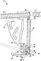
- exemplary embodiments of hydraulically driven tracker systems 412could employ a torsional relief function in the form of an over-pressure relief valve 418 to allow the tracker 412 to move to an extreme position in conditions where the tracker is exposed to excess wind force.
- a double acting hydraulic ram 460or cylinder, as shown in FIG. 13 , could be used to drive the hydraulic tracker 412 .
- Exemplary embodiments of a hydraulic ram 460has a rod 461 , which could be a rod, seal 465 and other sealing components 463 , an extend port 462 and a retract port 464 .
- the linear motion of hydraulic ram 460may be converted into rotary motion and used in a push/pull tracker design, discussed above with reference to FIGS. 10-11 .
- hydraulic ram 460may be fitted with an over-pressure valve 418 such as the one shown in FIG. 14 .
- An exemplary over-pressure valve 418has a spring 472 contained within the valve bonnet 476 .
- a seat disc 478is held by a disc holder 480 within body 474 .
- the valve 418may further comprise a blowdown adjustment ring 482 and a nozzle 484 .
- the over-pressure valve 418may be incorporated into the hydraulic fluid circuit between the two chambers of the hydraulic ram 460 that positions and holds the rotational position, i.e., it may be located between the extend port 462 and the retract port 464 of the hydraulic ram 460 .
- the over-pressure relief valve 418is designed or set to open at a pre-set pressure to release excess torsion externally applied to the tracking system 412 .
- the pressureis relieved by allowing the pressurized fluid to flow between the two chambers of the hydraulic ram, pressure controlled by the valve 418 .
- An air actuated tracker systemcould also employ a wind induced torsion relief in the form of an over-pressure relief valve to achieve the same function.
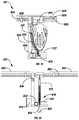
- a gear rack 814is coupled to the torsion tube 834 of a solar tracker assembly 812 and may also be attached to a support column 832 of the tracker assembly. More particularly, the gear rack 814 may be affixed to the torsion tube 834 via torsion tube bearing assemblies 836 and coupler 823 .
- the gear box 824has an internal clutch (not shown) located at an output of the gear assembly 820 , which includes the gear rack 814 , a pinion gear 815 with pinion gear shaft 817 , and may include a gear shaft end bearing.
- the systemmay have a gear drive upright column assembly with a driving motor 821 and driving the gearbox 824 .
- One or more photovoltaic modules 842may be coupled to the torsion tube 834 using module mounting brackets 835 .
- FIG. 17shows a detail view of the end travel position of the gear rack 814 and the engagement of the pinion gear 815 .
- the pins 825 of the gear rack 814are advantageously positioned at or near the end of the gear rack 814 to effect a stop as the pinion gear 815 rolls into the changed positioning of the pins 825 .
- the pinion 815may have center ridged pins 825 and a slotted pinion gear. This arrangement advantageously assures that the pinion gear 815 contacts only the pins 825 of the gear rack 814 and not the side plates of the gear rack.
- a single motorized solar tracker 512incorporates a torsion limiter device which could be a motor brake 518 .
- a motor brakewould affix to an electrical motor.
- the motor brake 518may include any suitable combination of pressure plate and disc components.
- the internal componentsinclude a stationary disc 521 as well as one or more rotating friction discs 523 having a hub and shaft.
- the brakeis electrically released during motor operation and engaged when the motor is de-energized.
- a pressure plate 525pushes against the discs, and a self-adjusting mechanism 527 may be provided to adjust the pressure on the discs.
- a release lever 529allows for manual release of the pressure.
- an individual motorcould be located at each array.
- a gearing system that is capable of being bi-directionally drivencould be coupled to a motor and a motor brake 518 at each array.
- the motorcould have a brake in the motor system or use itself as a brake. With the proper sizing of the motor, the brake, and the gear ratio and gear efficiency, the motor or motor brake 518 may act as the wind force release in the system.
- the drive systemcomprises a bi-directional gearbox 514 , and the motor brake 518 is located at the input of the gearbox 514 .
- the bi-directional gearingcan be driven from the gearbox input or output and has the capability to be driven from either the output or the input.
- the bi-directional gearingcould be any suitable gear, including but not limited to a spur gear, helical gear, planetary gear, high efficiency low ratio worm gear, belt drive, chain drive or other bi-directional drive arrangements.
- the torque in the torsion tube 34is reduced by the gear ratio of the bi-directional gearing, which overcomes the motor brake force. Then the torsion is released at the output and the tracker array rotates.
- the motor brake 518is configured to lock the solar tracker 512 in position until a pre-set torque limit is reached, at which time the motor brake slips.
- Exemplary embodimentscould incorporate a mechanical brake within the motor or affixed between the motor and the gear drive. If the motor itself has a separate brake as in FIG. 21 , then the motor may be sized for moving the array separately from the torsion release force required to hold the array.
- the motor brakecould be a brush-type direct current motor 618 that has the input power leads, such as lead wire 635 , shorted to effect a brake action on the motor output.
- the motoritself may be used as a the slip clutch for the external torsion to overcome.
- a DC brush-type motor 618 with its power leads shorted togetheract as a brake by turning the motor into a generator with a shorted output, making the motor difficult to turn.
- brush-type motor 618has an internal commutator 631 to periodically reverse the direction of the current and at least one brush 633 in contact with the commutator to complete the switch.
- FIG. 22shows an exemplary method of shorting out a motor, in this exemplary embodiment brush motor 618 , so it acts as a shorted out generator.
- the H-Bridgeturns on the motor and the motor may be shorted out via relay 619 .
- the brush motor 618acts like a fully-loaded generator so it is hard to turn and acts as a brake on the solar tracking system.
- the motor 618may incorporate a brake 637 , which could be a negative actuated-type electromagnetic brake.
- a motor brakecould be incorporated in any one of a variety of solar tracker assemblies, including but not limited to an individually motorized single, multi-stage or bi-directional gear driven system.
- an external forcecauses a level of torsion on the drive system to exceed the pre-set limit the motor brake is overcome and facilitates back-driving of the drive system.
- An exemplary bearing stop assembly 70comprises a bearing housing 72 , a dry slide bearing 74 and an internal rotating stop block 76 .
- FIG. 23Bdepicts the stop block 76 engaged at one side of its limit of rotation, i.e., one extreme stop position.
- FIG. 23Cshows the stop block 76 in middle position, i.e., in the middle of the allowed rotational motion.
- FIG. 23Dshows the stop block 76 at the opposite extreme stop position of FIG. 23B .
- the bearing stop assembliesmay be placed at every column and may be attached to the torsion tube 34 .
- Bearing stop assemblies 70advantageously provide the triple function of supporting the solar tracker array, providing a bearing on which the array can rotate, and, as discussed in detail herein, functioning as mechanical stops at the trackers' maximum rotational positions.
- the housingmay be coated with a low friction coating to prevent stick or slip action in the slow moving bearings.
- FIGS. 24A-24Cillustrate another exemplary embodiment of a tracker bearing stop assembly 170 with integral grounding.
- An exemplary assembly 170comprises a bearing housing 172 , a pin and roller bearing wheels 173 , a dry slide top half bushing 174 and an internal rotating stop block 176 .
- this designmay provide better performance in dusty environments and also provides a continuously electrically conductive grounding path, eliminating the need for an external ground wire to electrically bond the torsion tube to the column.
- an exemplary embodiment of a bearing stop assembly 70can be seen fully mounted in a solar tracker application where the solar tracker 12 has photovoltaic modules 42 mounted to the torsion tube 34 with special module mounting brackets.
- An additional bracketmay be provided which allows a damper to be connected between the torsion tube 34 and the support column 32 of the tracker.
- a dampermay be incorporated at the gear drive to control the rate at which the tracker rotates during an over torque event.
- the speed at which the array is allowed to movemay be controlled by the slip friction of the clutch, or by an external damper or both.
- the bearing stop assembly 70is connected to a U-bracket 78 that connects to an I-beam column 80 .
- the bearing stop assembly 70is mounted to an exemplary octagonal torsion tube 34 , such that the torsion tube runs through the center of the bearing stop assembly.
- the torsion tubecould be any cross-sectional shape including but not limited to circular, rounded, ovular, square, rectangular, triangular, pentagonal, hexagonal, and octagonal.
- the stop block 76 in the bearing stop assembly 70may be configured as a ring which conforms to the outside shape of the torsion tube 34 so that it is keyed to the outside of the tube and rotates with the tube.
- the dry-slide bearing 74also conforms to the outside shape of the torsion tube 34 and rotates with the tube. As shown in FIG. 23A , the dry slide bearing 74 may be octagonal on the internal and round on the external. The round external shape of the dry-slide bearing 74 slides on the round internal shape of the bearing housing 72 . This interface of the external surface of the dry-slide bearing 74 and the internal surface of the bearing housing 72 forms the bearing surface. In exemplary embodiments, the bearing surface of the bearing housing 72 may be coated with a low friction coating to reduce friction in the bearing.
- the dry-slide bearing 74is typically formed from polymer material and may also incorporate friction-lowering agents in its composition to reduce friction. When the torsion tube 34 is rotated to the mechanical limits, the stop block 76 engages the bearing housing to eliminate further rotation of the torsion tube 34 . There are therefore two extreme rotational stop positions created by the stop block 76 .
- the windinduces a hinge moment M H on the gear-driven mechanical system 10 .
- the clutchmay be pre-set to slip at a fraction of the maximum induced hinge moment torque.
- the friction of the clutch 18 on the tapers 26is overcome and the clutch 18 slips.
- the clutch 18acts like a pressure relief valve for the hinge moment M H induced by the wind, advantageously releasing the torque on the gear-driven mechanical unit 12 .
- a row of gear-driven mechanical units 12may rotate out of position and into a lower hinge moment position.
- the torsion limiting deviceWhen the torsion exerted externally on the output of the gear drive system (the collector array) exceeds a pre-set limit, the torsion limiting device allows the array to move into a new position until the force has diminished below the torsion threshold or the array has reached its mechanical limits. In the case where the torsion exerted from the input exceeds the pre-set torsion limit on the array, the torsion limiting device de-couples the excess input force and allows the input to move without affected movement on the array. As discussed in more detail herein, this may be used to synchronize linked arrays when driven against a mechanical stop, or used when natural occurrences such as snow drifts or sand impede array movement. In this case, it is advantageous to de-couple the input driving forces with the torsion limiter and hold the array output at position.
- the solar array or other gear-driven mechanical unit 12rotates to another position. If this excess torque continues from the wind, then each mechanical unit 12 and the array 50 of units moves to its maximum angle of rotation 54 , an extreme rotational angle where the torsion force can be resisted at multiple locations on the torsion tube 34 .
- the row of mechanical units 12may be rotated by the wind until the maximum angle stop is reached.
- the systemmay hit mechanical stops 58 on each row of mechanical units 12 each time the row moves to an extreme position during normal operation. Allowing the external force to rotate the row of solar trackers while driving the other rows of solar trackers allows each row to reach its maximum limit position until all of rows of solar trackers are aligned.
- thisensures alignment of all rows of units 12 twice a day in the event that the wind moves a row. This ensures that all the rows are exactly synchronized at least once per day.
- the tracker rowsmay be pointing all directions, but after a calibration, the rows would be completely synchronized.
- the clutch 18may act independently at each tracker row. This is because having a back-drivable linked system that has to back drive all tracker rows may not react properly to protect each row when the wind force is applied individually to a row.
- the rotation speedmay be regulated by the clutch slip force.
- the clutch 18may de-couple the dynamic loads on the system by eliminating the spring in the system, thereby significantly reducing the design loads.
- dampers 58may be provided to slow the motion of the tracker. The max angle stop may then be resisted not only by the gear rack, but by the dampers at the gear rack or stops 58 at the end of the rows of mechanical units 12 , thereby sharing the torsion load of the gear rack 60 and distributing the torsion load through multiple points on the torsion tube 34 .
- the dampers 58may serve double duty as stops at the end of the array, or dampers placed at any location may be designed to assist in regulating the torsional release reaction speed and resisting the hinge moment loads.
- exemplary embodimentsreduce the maximum hinge moment, eliminate the dynamic loading, and allow gear-driven mechanical systems to resist the hinge moment forces at multiple points on the array instead of at a single point. It is typical that the hinge moment forces are greater at small tilt angles and reduce as the array tilt angles increase. In exemplary embodiments, at the extreme vertical stop positions, the maximum hinge moment force will be less than at the small angles of rotation and will only occur at the mechanical stops at the range of motion extremes. The total hinge moment may be resisted in more than just the central gear. Range of motion mechanical stops may be placed at any location on the array, typically at the distributed vertical supports, to assist in resisting the hinge moment loading, thereby minimizing torsion loads at any single point in the system.
- the maximum hinge momentmay be x ft lbs, and the clutch 18 slips at about x/4 ft lbs. Accordingly, the torsion tube 34 need only resist a maximum of x/4 ft lbs at the gear drive 16 prior to the clutch 18 slipping.
- the maximum hinge momentis about x ft lbs
- the gear resists x/2 ft lbs and the stops located at the ends of the trackermust resist x/4 ft lbs so the maximum torsion load in the tube 34 is x/4 ft lbs.
- the maximum torsion valueswould likely be double in each component without advantageous use of exemplary embodiments of the clutch and multiple stops. These values can be reduced further by allowing the torsion release to occur at lower values and using more stops than only at the ends of the array, such as at every column.
- the driveline and the gear rackwould not see one gear rack 14 stopping the force from the motor 15 . Accordingly, the gear rack and the driveline can be more minimally constructed. Moreover, exemplary systems would need only be constructed to see the motion restricted to the everyday range of motion and over travel protection could be incorporated into the torsion limiter.
- the dampers 58 and gear rack 14may be optimally designed and implemented at full range of motion. No extra tolerance on range of motion is necessary other than the daily range of motion.
- one row of mechanical units 12may not affect the rest of the system 10 . This may be helpful as it may self-diagnose a tracker row binding problem. If the outer rows move to an extreme angle from the wind, they may act as wind blockers to the inner rows. Because the forces of lift, drag and hinge moment occur in combination on the system and each of these loads may peak at different specific rotational angle positions, it may be advantageous to allow a row of mechanical units to move into a more extreme angle position prior to the maximum lift force condition occurring. If this is reliably accomplished via the torsion limiters discussed herein, then the foundation design value for maximum lift will be lower and therefore the size and/or depth required for the system foundation may be lessened to resist the lower lift force.
- the torsional strength requirementsmay be less because the maximum torsion can be resisted at multiple points and not at the maximum rotational angle for peak hinge moment.
- the drag force peakmay not change since the system typically is designed for the extreme rotational angle position in the case of horizontal solar trackers, but may be lessened in other solar tracker geometries.
- the maximum combined forcemay also be less, in which case the overall structural requirements will be lessened.
- torsion limiter devices, systems, and methods incorporated into systems such as solar trackersare provided. While the systems, devices, and methods have been described in terms of exemplary embodiments, it is to be understood that the disclosure need not be limited to the disclosed embodiments. Although illustrative embodiments are described hereinabove, it will be evident to one skilled in the art that various changes and modifications may be made therein without departing from the disclosure.
Landscapes
- Engineering & Computer Science (AREA)
- Physics & Mathematics (AREA)
- General Engineering & Computer Science (AREA)
- Life Sciences & Earth Sciences (AREA)
- Sustainable Development (AREA)
- Mechanical Engineering (AREA)
- Chemical & Material Sciences (AREA)
- Sustainable Energy (AREA)
- Thermal Sciences (AREA)
- Combustion & Propulsion (AREA)
- General Physics & Mathematics (AREA)
- Radar, Positioning & Navigation (AREA)
- Remote Sensing (AREA)
- Electromagnetism (AREA)
- Photovoltaic Devices (AREA)
- Gear Transmission (AREA)
- Transmission Devices (AREA)
- Wind Motors (AREA)
Abstract
Description
| Symbol | Feature or Characteristic | ||
| As | Module Surface Area | ||
| MH | Hinge Moment due to wind loading | ||
| MG | Total Ground Moment Reaction | ||
| RD | Ground Drag Reaction | ||
| RL | Ground Lift Reaction | ||
| Θ | Tracker Angle from y-axis | ||
| FD | Drag Force due to wind loading | ||
| FL | Lift Force due to wind loading | ||
| qz | Dynamic Velocity Pressure of wind | ||
| Γ | Yaw Angle of Wind from the y-axis | ||
As mentioned above and described in more detail herein, exemplary torsion limiters and related gear drives and solar trackers reduce or eliminate the hinge moment on the tracker.
Claims (22)
Priority Applications (2)
| Application Number | Priority Date | Filing Date | Title |
|---|---|---|---|
| US16/055,663US10809345B2 (en) | 2014-02-19 | 2018-08-06 | Torque limiter devices, systems and methods and solar trackers incorporating torque limiters |
| US17/014,850US11454693B2 (en) | 2014-02-19 | 2020-09-08 | Torsion limiter devices, systems and methods and solar trackers incorporating torsion limiters |
Applications Claiming Priority (5)
| Application Number | Priority Date | Filing Date | Title |
|---|---|---|---|
| US201461941754P | 2014-02-19 | 2014-02-19 | |
| US201462065741P | 2014-10-19 | 2014-10-19 | |
| US14/624,930US9581678B2 (en) | 2014-02-19 | 2015-02-18 | Torque limiter devices, systems and methods and solar trackers incorporating torque limiters |
| US15/437,488US10042030B2 (en) | 2014-02-19 | 2017-02-21 | Torque limiter devices, systems and methods and solar trackers incorporating torque limiters |
| US16/055,663US10809345B2 (en) | 2014-02-19 | 2018-08-06 | Torque limiter devices, systems and methods and solar trackers incorporating torque limiters |
Related Parent Applications (1)
| Application Number | Title | Priority Date | Filing Date |
|---|---|---|---|
| US15/437,488ContinuationUS10042030B2 (en) | 2014-02-19 | 2017-02-21 | Torque limiter devices, systems and methods and solar trackers incorporating torque limiters |
Related Child Applications (1)
| Application Number | Title | Priority Date | Filing Date |
|---|---|---|---|
| US17/014,850ContinuationUS11454693B2 (en) | 2014-02-19 | 2020-09-08 | Torsion limiter devices, systems and methods and solar trackers incorporating torsion limiters |
Publications (2)
| Publication Number | Publication Date |
|---|---|
| US20180348331A1 US20180348331A1 (en) | 2018-12-06 |
| US10809345B2true US10809345B2 (en) | 2020-10-20 |
Family
ID=53797948
Family Applications (4)
| Application Number | Title | Priority Date | Filing Date |
|---|---|---|---|
| US14/624,930Active2035-07-05US9581678B2 (en) | 2014-02-19 | 2015-02-18 | Torque limiter devices, systems and methods and solar trackers incorporating torque limiters |
| US15/437,488Active2035-05-01US10042030B2 (en) | 2014-02-19 | 2017-02-21 | Torque limiter devices, systems and methods and solar trackers incorporating torque limiters |
| US16/055,663ActiveUS10809345B2 (en) | 2014-02-19 | 2018-08-06 | Torque limiter devices, systems and methods and solar trackers incorporating torque limiters |
| US17/014,850ActiveUS11454693B2 (en) | 2014-02-19 | 2020-09-08 | Torsion limiter devices, systems and methods and solar trackers incorporating torsion limiters |
Family Applications Before (2)
| Application Number | Title | Priority Date | Filing Date |
|---|---|---|---|
| US14/624,930Active2035-07-05US9581678B2 (en) | 2014-02-19 | 2015-02-18 | Torque limiter devices, systems and methods and solar trackers incorporating torque limiters |
| US15/437,488Active2035-05-01US10042030B2 (en) | 2014-02-19 | 2017-02-21 | Torque limiter devices, systems and methods and solar trackers incorporating torque limiters |
Family Applications After (1)
| Application Number | Title | Priority Date | Filing Date |
|---|---|---|---|
| US17/014,850ActiveUS11454693B2 (en) | 2014-02-19 | 2020-09-08 | Torsion limiter devices, systems and methods and solar trackers incorporating torsion limiters |
Country Status (13)
| Country | Link |
|---|---|
| US (4) | US9581678B2 (en) |
| EP (1) | EP3108186B1 (en) |
| JP (1) | JP6230718B2 (en) |
| KR (1) | KR101796599B1 (en) |
| CN (1) | CN106062489B (en) |
| AP (1) | AP2016009388A0 (en) |
| AU (1) | AU2015219130B2 (en) |
| BR (1) | BR112016018940B1 (en) |
| ES (1) | ES2869876T3 (en) |
| MX (1) | MX363114B (en) |
| PT (1) | PT3108186T (en) |
| SA (1) | SA516371694B1 (en) |
| WO (1) | WO2015126890A1 (en) |
Cited By (11)
| Publication number | Priority date | Publication date | Assignee | Title |
|---|---|---|---|---|
| USD940547S1 (en) | 2019-12-13 | 2022-01-11 | Array Technologies, Inc. | Clamp |
| US11360492B2 (en) | 2019-10-02 | 2022-06-14 | Array Technologies, Inc. | Solar tracking system |
| USD956538S1 (en) | 2020-05-08 | 2022-07-05 | Array Technologies, Inc. | Mounting hardware |
| USD956537S1 (en) | 2020-05-08 | 2022-07-05 | Array Technologies, Inc. | Mounting hardware |
| USD956536S1 (en) | 2020-05-08 | 2022-07-05 | Array Technologies, Inc. | Mounting hardware |
| US11454693B2 (en) | 2014-02-19 | 2022-09-27 | Array Technologies, Inc. | Torsion limiter devices, systems and methods and solar trackers incorporating torsion limiters |
| US11527988B2 (en) | 2020-05-13 | 2022-12-13 | Array Technologies, Inc. | Mounting bracket extension |
| USD979390S1 (en)* | 2019-11-12 | 2023-02-28 | Don Girard | Tube clamp liner |
| USD987421S1 (en) | 2020-12-11 | 2023-05-30 | Array Technologies, Inc. | Clamp |
| US20230370015A1 (en)* | 2021-02-09 | 2023-11-16 | Array Tech, Inc. | Geared drive system providing intermittent motion |
| US12031750B2 (en) | 2019-12-13 | 2024-07-09 | Array Tech, Inc. | Modified clamp |
Families Citing this family (59)
| Publication number | Priority date | Publication date | Assignee | Title |
|---|---|---|---|---|
| US10277159B2 (en) | 2008-11-17 | 2019-04-30 | Kbfx Llc | Finished multi-sensor units |
| US11063553B2 (en)* | 2008-11-17 | 2021-07-13 | Kbfx Llc | Solar carports, solar-tracking carports, and methods |
| US11035591B2 (en)* | 2015-10-13 | 2021-06-15 | Corosolar Llc | Bearing assembly for solar trackers |
| US12294332B2 (en) | 2015-12-15 | 2025-05-06 | Kbfx Llc | Solar carports, solar-tracking carports, and methods |
| CN105790691A (en)* | 2016-04-15 | 2016-07-20 | 无锡凯能光伏设备有限公司 | Solar power generation tracking bracket provided with safety protection device |
| KR102341671B1 (en)* | 2016-06-12 | 2021-12-20 | 어레이 테크놀로지 인코퍼레이티드 | How to mount clip-on mounting rails, mounting brackets and solar modules |
| MX2019000053A (en)* | 2016-07-08 | 2019-05-02 | Alion Energy Inc | Systems and methods for rotatably mounting and locking solar panels. |
| US10174970B2 (en)* | 2016-09-09 | 2019-01-08 | Sunpower Corporation | Sun tracking solar energy collection system with torsion lock |
| FR3056363A1 (en)* | 2016-09-22 | 2018-03-23 | Jean-Luc Batel | FOLLOWER SUPPORT FOR SOLAR PANEL |
| PL3589899T3 (en)* | 2017-03-02 | 2023-05-02 | Array Technologies, Inc. | Counterbalance spring assemblies and solar trackers containing counterbalance spring assemblies |
| EP3425305A1 (en)* | 2017-07-07 | 2019-01-09 | Hanlog Oy | Solar panel arrangement |
| US11855581B2 (en)* | 2017-07-18 | 2023-12-26 | Polar Racking Inc. | Solar panel support and drive system |
| CN107525290B (en)* | 2017-08-31 | 2019-06-18 | 山东奇威特太阳能科技有限公司 | Solar thermal collector cleans head shade |
| US11416010B2 (en) | 2018-02-13 | 2022-08-16 | FCX Solar LLC | System and method for flexible solar tracker and testing |
| EP3753102B1 (en)* | 2018-02-13 | 2024-01-17 | FCX Solar LLC | Solar tracker system |
| US20190296687A1 (en)* | 2018-03-23 | 2019-09-26 | Nextracker Inc. | Structural beam for solar tracker |
| US11283395B2 (en) | 2018-03-23 | 2022-03-22 | Nextracker Inc. | Multiple actuator system for solar tracker |
| DE202018103053U1 (en)* | 2018-05-30 | 2018-06-08 | Ideematec Deutschland Gmbh | Solar system with swiveling and lockable module table |
| US11387771B2 (en) | 2018-06-07 | 2022-07-12 | Nextracker Llc | Helical actuator system for solar tracker |
| ES2870227T3 (en)* | 2018-08-06 | 2021-10-26 | Soltec Energias Renovables Sl | Single axis solar tracker with torsional vibration damping device |
| CN111102392B (en)* | 2018-10-26 | 2022-01-11 | 浙江三花智能控制股份有限公司 | Control system and control method of electric valve |
| US11509258B2 (en)* | 2018-12-14 | 2022-11-22 | Xirasol Pty Ltd | Solar tracking installation |
| CN109404454A (en)* | 2018-12-24 | 2019-03-01 | 重庆工业职业技术学院 | A kind of mechanical limiting mechanism |
| CN109597434A (en)* | 2019-01-21 | 2019-04-09 | 江苏中信博新能源科技股份有限公司 | Wind turns round the photovoltaic tracking system of dispersion |
| EP3942688A4 (en)* | 2019-03-21 | 2022-12-21 | Ojjo, Inc. | Moment optimized truss foundations for single-axis trackers |
| US10917036B2 (en)* | 2019-05-01 | 2021-02-09 | Jan Christopher Schilling | Tilting solar panel mount |
| US11050383B2 (en) | 2019-05-21 | 2021-06-29 | Nextracker Inc | Radial cam helix with 0 degree stow for solar tracker |
| CN110939703A (en)* | 2019-11-21 | 2020-03-31 | 浙江正泰新能源开发有限公司 | Photovoltaic tracker deceleration system |
| PT3839371T (en)* | 2019-12-16 | 2023-07-28 | Soltec Innovations Sl | Solar tracker |
| CN111030585B (en)* | 2019-12-31 | 2021-01-01 | 山东蓝迪照明科技有限公司 | Solar photovoltaic power generation system for industrial factory building |
| US11569780B2 (en)* | 2020-03-17 | 2023-01-31 | Sun And Steel Solar Llc | Purlin system for solar module attachment |
| WO2022146527A1 (en)* | 2020-12-28 | 2022-07-07 | Gamechange Solar Corp. | Single axis solar tracker drive wheel assembly |
| CN111431475A (en)* | 2020-04-27 | 2020-07-17 | 上海摩昆新能源科技有限公司 | Photovoltaic tracking support and transmission device thereof |
| CN211557214U (en)* | 2020-04-27 | 2020-09-22 | 上海摩昆新能源科技有限公司 | Photovoltaic tracking support and transmission device thereof |
| US11139775B1 (en) | 2020-07-14 | 2021-10-05 | FTC Solar, Inc. | Systems and methods for terrain based backtracking for solar trackers |
| US11108353B1 (en) | 2020-07-14 | 2021-08-31 | FTC Solar, Inc. | Systems and methods for array level terrain based backtracking |
| US11522491B2 (en) | 2020-08-26 | 2022-12-06 | FTC Solar, Inc. | Systems and methods for adaptive range of motion for solar trackers |
| US11984841B2 (en)* | 2020-09-08 | 2024-05-14 | Nextracker Llc | Distributed locking tracker |
| US10935992B1 (en) | 2020-09-16 | 2021-03-02 | FTC Solar, Inc. | Systems and methods for solar trackers with diffuse light tracking |
| ES2950742R1 (en)* | 2020-12-03 | 2024-04-10 | Gamechange Solar Corp | Solar tracker with improved damping |
| US11757402B2 (en) | 2020-12-14 | 2023-09-12 | Nevados Engineering, Inc. | Integrated articulated bearing |
| WO2022132739A2 (en)* | 2020-12-14 | 2022-06-23 | Nevados Engineering, Inc. | Variable terrain solar tracker |
| US11209337B1 (en) | 2021-07-01 | 2021-12-28 | FCX Solar LLC | System and method for flexible solar tracker and testing |
| EP4117177A1 (en)* | 2021-07-07 | 2023-01-11 | Soltec Innovations, S.L. | Solar tracker with brake control |
| US11695370B2 (en) | 2021-07-27 | 2023-07-04 | FTC Solar, Inc. | Locking assembly for a solar photovoltaic array tracker |
| CN113746412B (en)* | 2021-09-15 | 2025-05-02 | 江苏曦日新能源科技有限公司 | Multi-point rotary drive photovoltaic power generation tracking bracket |
| CN219178009U (en)* | 2021-10-28 | 2023-06-13 | 上海施步新能源科技有限公司 | Solar bracket with damping mechanism |
| AU2022400770A1 (en)* | 2021-11-30 | 2024-06-06 | Nextracker Llc | Systems and methods for tracker-level protection |
| AU2022409837A1 (en) | 2021-12-16 | 2024-06-27 | FTC Solar, Inc. | Solar tracker system including a frame assembly |
| AU2023275488A1 (en)* | 2022-05-25 | 2024-12-05 | Array Tech, Inc. | Torque limiting mechanism for solar tracking systems |
| US11988260B2 (en) | 2022-05-25 | 2024-05-21 | Array Technologies, Inc. | Torque limiting mechanism for solar tracking systems |
| ES1293486Y (en)* | 2022-06-21 | 2022-10-24 | Trina Solar S L U | BEARING FOR FASTENING OF ROTATING SHAFTS ON SUPPORTING PILLARS |
| JP7217567B1 (en)* | 2022-11-16 | 2023-02-03 | 株式会社Qdジャパン | solar tracker |
| WO2024243167A1 (en)* | 2023-05-24 | 2024-11-28 | Nextracker Llc | Bearing housing assemblies for solar trackers |
| EP4477968B1 (en)* | 2023-06-14 | 2025-10-15 | Trina Solar Spain, S.L.U. | Passive locking system for solar tracker |
| WO2025085053A1 (en)* | 2023-10-17 | 2025-04-24 | Array Tech, Inc. | System for reducing torsional deflection in solar tracker torque tubes |
| JP2025117179A (en)* | 2024-01-30 | 2025-08-12 | 景欣股▲分▼有限公司 | Solar panel bracket |
| WO2025193153A1 (en)* | 2024-03-13 | 2025-09-18 | Vaja Ab | Solar panel suspension system comprising a blocking structure |
| WO2025193149A1 (en) | 2024-03-13 | 2025-09-18 | Vaja Ab | A solar tracker system |
Citations (76)
| Publication number | Priority date | Publication date | Assignee | Title |
|---|---|---|---|---|
| US4122827A (en) | 1977-08-25 | 1978-10-31 | Rhodes William A | Kinematic synchronous solar heliostat |
| JPS55131648A (en) | 1979-03-31 | 1980-10-13 | Takashi Mori | Driving mechanism for sunlight tracking apparatus |
| US4264145A (en) | 1978-09-14 | 1981-04-28 | Sener, Ingenieria Y Sistemas, S.A. | Invertible apparatus for the reflection of solar radiation |
| US4295621A (en) | 1980-03-18 | 1981-10-20 | Rca Corporation | Solar tracking apparatus |
| US4321909A (en) | 1975-07-11 | 1982-03-30 | Vulcan Australia Limited | Servo-controlled solar tracking apparatus |
| US4323052A (en) | 1979-01-05 | 1982-04-06 | Virgil Stark | Solar energy system |
| US4340812A (en) | 1979-03-26 | 1982-07-20 | Kei Mori | Radiation energy collection and tracking apparatus |
| US4354484A (en) | 1981-01-05 | 1982-10-19 | Transolar, Inc. | Solar collection system |
| US4572161A (en) | 1983-06-24 | 1986-02-25 | Kei Mori | Solar ray collector device |
| CH659123A5 (en) | 1983-03-25 | 1986-12-31 | Atlantis Energie Ag | Reflector for concentrating solar energy on a stationary absorber |
| JPS6410809U (en) | 1987-07-06 | 1989-01-20 | ||
| US4866918A (en) | 1988-11-01 | 1989-09-19 | Deere & Company | Torque limiting drive arrangement for a cotton harvester with multiple row units |
| US5080642A (en) | 1989-11-20 | 1992-01-14 | Mitsubishi Denki Kabushiki Kaisha | Rotation transmission device with a torque limiting transmission gear mechanism |
| US5228924A (en) | 1991-11-04 | 1993-07-20 | Mobil Solar Energy Corporation | Photovoltaic panel support assembly |
| US5241871A (en) | 1992-10-23 | 1993-09-07 | United Technologies Motor Systems, Inc. | Torque limiting starter drive clutch assembly |
| JPH0615284A (en) | 1992-07-01 | 1994-01-25 | Nippon Kentetsu Co Ltd | Water treatment apparatus |
| WO1995000806A1 (en) | 1993-06-17 | 1995-01-05 | Devappa | Device for generating electric power from solar energy |
| US5730014A (en) | 1996-08-16 | 1998-03-24 | Securitech Group, Inc. | Vandal-resistant torque sensitive release mechanism |
| US6280331B1 (en) | 1999-02-16 | 2001-08-28 | Hubbell Incorporated | Torque limiting slip clutch apparatus for cable reel drive assembly |
| CN1339683A (en) | 2000-08-17 | 2002-03-13 | 王建军 | Variable spring automatic sun following machine |
| US6464217B1 (en) | 1999-11-12 | 2002-10-15 | Pitney Bowes Inc. | Method and apparatus for limiting torque in a feeder |
| US6563040B2 (en)* | 2001-10-11 | 2003-05-13 | Pinnacle West Capital Corporation | Structure for supporting a photovoltaic module in a solar energy collection system |
| US20050284467A1 (en) | 2002-10-17 | 2005-12-29 | Patterson Michael T | Solar tracking apparatus |
| DE102004044841A1 (en) | 2004-09-13 | 2006-03-30 | Deutsches Zentrum für Luft- und Raumfahrt e.V. | Heliostat device and method for adjusting mirror surfaces of a heliostat device |
| US20060096586A1 (en) | 2004-11-09 | 2006-05-11 | Arizona Public Service Company | Positioning system and method of orienting an object using same |
| US20070034205A1 (en) | 2005-08-15 | 2007-02-15 | Watts Phillip C | Solar parabolic trough, receiver, tracker and drive system |
| US7197383B2 (en) | 2004-02-17 | 2007-03-27 | Ford Global Technologies, Llc | System for limiting reactive torque in powertrains |
| EP1791184A1 (en) | 2005-11-29 | 2007-05-30 | Dr. H. Frauenknecht GmbH | Solar power system and method of operation |
| DE102006028230A1 (en) | 2006-06-20 | 2007-12-27 | Schöll, Georg | Crack safety device for preventing transmission breaks in e.g. tracking systems for solar system, has unlocking device released to overshoot maximum moment of drive, and spring-loaded disengaging unit providing automatic resetting |
| US20080128235A1 (en) | 2006-11-30 | 2008-06-05 | Luk Lamellen Und Kupplungsbau Beteiligungs Kg | Torque limiter and method for assemblying a torque limiter |
| WO2008147560A1 (en) | 2007-05-24 | 2008-12-04 | Megawatt Solar, Inc. | Photovoltaic collection systems, friction drives, and method for tracking the sun and avoiding wind damage |
| US20090095283A1 (en) | 2007-10-15 | 2009-04-16 | Gary Noble Curtis | Multiplexed torque brake system for a solar concentrator assembly |
| ES2326778A1 (en) | 2008-04-17 | 2009-10-19 | Promotora Nuevas Tecnicas, S.A. | Solar tracking device |
| ES2327988A1 (en) | 2005-10-28 | 2009-11-05 | Instalaciones Y Montajes Electricos Del Valle Aguayo, S.A. | Orientation system for solar followers or heliostatos (Machine-translation by Google Translate, not legally binding) |
| ES2329219A1 (en) | 2008-05-21 | 2009-11-23 | Sun Nest, S.L.U. | Actuation device enabling the relative rotation of structures and a solar tracker |
| US20090320827A1 (en) | 2006-06-28 | 2009-12-31 | Thompson Technology Industries, Inc. | Solar array tracker controller |
| ES2334187A1 (en) | 2006-10-03 | 2010-03-05 | Manuel Lahuerta Romeo | Solar follower of three axes of great surface (Machine-translation by Google Translate, not legally binding) |
| JP2010067716A (en) | 2008-09-09 | 2010-03-25 | Mitsubishi Electric Corp | Photovoltaic power generating device |
| WO2010054831A2 (en) | 2008-11-14 | 2010-05-20 | Werner Kaufmann | A solar panel support apparatus |
| US20100166843A1 (en) | 2007-02-01 | 2010-07-01 | Sigma-Tau Industrie Farmaceutiche Riunite S.P.A. | Pharmaceutical composition comprising a campothecin derivative |
| CN201523017U (en) | 2009-10-15 | 2010-07-07 | 晃益齿轮工业股份有限公司 | Sun Tracking System Device |
| US20100185333A1 (en) | 2009-01-22 | 2010-07-22 | Kenneth Oosting | Feedforward control system for a solar tracker |
| US20100223865A1 (en) | 2009-03-04 | 2010-09-09 | Mecanizados Solares, S.L. | Support of a solar tracker |
| US7836879B2 (en) | 2004-08-10 | 2010-11-23 | Kevin Keith Mackamul | Tracker drive system and solar energy collection system |
| US7850577B2 (en) | 1997-02-18 | 2010-12-14 | Nautilus, Inc. | Free wheel clutch mechanism for bicycle drive train |
| WO2011056742A1 (en) | 2009-11-04 | 2011-05-12 | Ssw Holding Company, Inc. | Cooking appliance surfaces having spill containment pattern and methods of making the same |
| GB2481401A (en) | 2010-06-22 | 2011-12-28 | Athene Works Ltd | Apparatus for generating electricity from incident solar radiation |
| KR101176025B1 (en) | 2011-01-31 | 2012-08-24 | 주식회사 에타 | Solar Tracking Louver System and Control Method Thereof |
| US8278547B2 (en)* | 2003-04-02 | 2012-10-02 | P4P Holdings Llc | Solar array support methods and systems |
| US8290207B2 (en) | 2009-12-29 | 2012-10-16 | Hon Hai Precision Industry Co., Ltd. | Solar power device |
| JP2012204471A (en) | 2011-03-24 | 2012-10-22 | Daido Steel Co Ltd | Photovoltaic generation device |
| US20120285279A1 (en) | 2011-05-10 | 2012-11-15 | Jeremie Alan Wade | Dual torque limiter |
| WO2013005721A1 (en) | 2011-07-07 | 2013-01-10 | 株式会社ユニバンス | Solar tracking device |
| GB2493329A (en) | 2011-07-14 | 2013-02-06 | Athene Works Ltd | Curved reflective surface for concentrating EM radiation with obstructing members |
| US8372082B2 (en) | 2009-07-30 | 2013-02-12 | Kyphon Sarl | Surgical apparatus with force limiting clutch |
| US8459249B2 (en) | 2007-06-15 | 2013-06-11 | Ronald P. Corio | Single axis solar tracking system |
| WO2013139745A2 (en) | 2012-03-19 | 2013-09-26 | Ideematec Deutschland Gmbh | Tracking device for solar modules |
| US20130341934A1 (en) | 2009-08-24 | 2013-12-26 | Eiji Kawanishi | Hybrid power generator coupled to gravity power generator using balance which has pressure load device |
| US20130341294A1 (en) | 2012-05-02 | 2013-12-26 | Gossamer Space Frames | Brake system and method for a rotating frame in a solar power generation system |
| US20130340807A1 (en) | 2012-06-26 | 2013-12-26 | Lockheed Martin Corporation | Foldable solar tracking system, assembly and method for assembly, shipping and installation of the same |
| JP2014049312A (en) | 2012-08-31 | 2014-03-17 | Minebea Co Ltd | Drive unit, and moving body-tracking device |
| DE202014000621U1 (en) | 2014-01-22 | 2014-03-25 | Markus Masur | Spring-cage coupling for breaking down wind-induced forces on solar trackers |
| US8697983B2 (en) | 2008-05-16 | 2014-04-15 | Suncore Photovoltaics, Inc. | Concentrating photovoltaic solar panel |
| US8877016B2 (en) | 2011-11-06 | 2014-11-04 | King Saud University | Solar steam generation |
| US20140338659A1 (en) | 2008-06-12 | 2014-11-20 | Ronald P. Corio | Single axis solar tracking system |
| MX2013014987A (en) | 2013-12-17 | 2015-06-17 | Caru Ardica S A De C V | Multi-staged centric flat speed reducer with magnetic coupling and torque limit coupled to heliostat mirrors. |
| US9170033B2 (en) | 2010-01-20 | 2015-10-27 | Brightsource Industries (Israel) Ltd. | Method and apparatus for operating a solar energy system to account for cloud shading |
| US9203343B2 (en) | 2011-05-26 | 2015-12-01 | Machtwissen.De Ag | Devices for optimizing individual solar modules/collector modules and composite collector module groups and stabilizing the operation thereof against environmental influences, especially wind and particles and objects carried along by the wind |
| US9236516B2 (en) | 2013-03-01 | 2016-01-12 | Glenn M. Goldsby | Solar energy collector apparatus |
| US9297879B2 (en) | 2009-03-13 | 2016-03-29 | Fraunhofer-Gesellschaft Zur Foerderung Der Angewandten Forschung E.V. | Method for tracking a solar generator to the sun, control for a solar plant and solar plant |
| US9355873B2 (en)* | 2011-08-04 | 2016-05-31 | King Abdullah University Of Science And Technology | Apparatuses, systems and methods for cleaning photovoltaic devices |
| US9581678B2 (en) | 2014-02-19 | 2017-02-28 | Array Technologies, Inc. | Torque limiter devices, systems and methods and solar trackers incorporating torque limiters |
| US9641123B2 (en)* | 2011-03-18 | 2017-05-02 | Alion Energy, Inc. | Systems for mounting photovoltaic modules |
| US20180152134A1 (en) | 2015-06-03 | 2018-05-31 | Optimum Tracker | Method for predictive control of the orientation of a solar tracker |
| US20180196117A1 (en) | 2015-07-02 | 2018-07-12 | Optimum Tracker | Method for controlling the orientation of a solar tracker based on cartographic models |
| US20200162016A1 (en) | 2016-06-12 | 2020-05-21 | Array Technologies, Inc. | Clip-on mounting rails, mounting brackets, and methods of mounting solar modules |
Family Cites Families (6)
| Publication number | Priority date | Publication date | Assignee | Title |
|---|---|---|---|---|
| US4429178A (en)* | 1981-07-13 | 1984-01-31 | Acurex Solar Corporation | Solar tracking apparatus utilizing photovoltaic flat panels and method |
| US7531741B1 (en)* | 2003-03-07 | 2009-05-12 | Sacred Power Corporation | Tracking solar shelter |
| JP5455735B2 (en)* | 2010-03-25 | 2014-03-26 | 株式会社東芝 | Solar power plant |
| CN202403437U (en)* | 2011-12-16 | 2012-08-29 | 张宗炜 | Passive tracking holder for solar device |
| JP5418652B1 (en)* | 2012-09-28 | 2014-02-19 | ダイキン工業株式会社 | Solar panel unit |
| US20140166843A1 (en)* | 2012-12-19 | 2014-06-19 | Rudi Bertocchi | Adaptive velocity tracker |
- 2015
- 2015-02-18KRKR1020167025161Apatent/KR101796599B1/enactiveActive
- 2015-02-18CNCN201580009424.7Apatent/CN106062489B/enactiveActive
- 2015-02-18JPJP2016550728Apatent/JP6230718B2/enactiveActive
- 2015-02-18ESES15751281Tpatent/ES2869876T3/enactiveActive
- 2015-02-18PTPT157512815Tpatent/PT3108186T/enunknown
- 2015-02-18BRBR112016018940-0Apatent/BR112016018940B1/enactiveIP Right Grant
- 2015-02-18AUAU2015219130Apatent/AU2015219130B2/enactiveActive
- 2015-02-18USUS14/624,930patent/US9581678B2/enactiveActive
- 2015-02-18WOPCT/US2015/016290patent/WO2015126890A1/enactiveApplication Filing
- 2015-02-18EPEP15751281.5Apatent/EP3108186B1/enactiveActive
- 2015-02-18MXMX2016010230Apatent/MX363114B/enunknown
- 2016
- 2016-08-18SASA516371694Apatent/SA516371694B1/enunknown
- 2016-08-31APAP2016009388Apatent/AP2016009388A0/enunknown
- 2017
- 2017-02-21USUS15/437,488patent/US10042030B2/enactiveActive
- 2018
- 2018-08-06USUS16/055,663patent/US10809345B2/enactiveActive
- 2020
- 2020-09-08USUS17/014,850patent/US11454693B2/enactiveActive
Patent Citations (82)
| Publication number | Priority date | Publication date | Assignee | Title |
|---|---|---|---|---|
| US4321909A (en) | 1975-07-11 | 1982-03-30 | Vulcan Australia Limited | Servo-controlled solar tracking apparatus |
| US4122827A (en) | 1977-08-25 | 1978-10-31 | Rhodes William A | Kinematic synchronous solar heliostat |
| US4264145A (en) | 1978-09-14 | 1981-04-28 | Sener, Ingenieria Y Sistemas, S.A. | Invertible apparatus for the reflection of solar radiation |
| US4323052A (en) | 1979-01-05 | 1982-04-06 | Virgil Stark | Solar energy system |
| US4340812A (en) | 1979-03-26 | 1982-07-20 | Kei Mori | Radiation energy collection and tracking apparatus |
| JPS55131648A (en) | 1979-03-31 | 1980-10-13 | Takashi Mori | Driving mechanism for sunlight tracking apparatus |
| US4295621A (en) | 1980-03-18 | 1981-10-20 | Rca Corporation | Solar tracking apparatus |
| US4354484A (en) | 1981-01-05 | 1982-10-19 | Transolar, Inc. | Solar collection system |
| CH659123A5 (en) | 1983-03-25 | 1986-12-31 | Atlantis Energie Ag | Reflector for concentrating solar energy on a stationary absorber |
| US4572161A (en) | 1983-06-24 | 1986-02-25 | Kei Mori | Solar ray collector device |
| JPS6410809U (en) | 1987-07-06 | 1989-01-20 | ||
| US4866918A (en) | 1988-11-01 | 1989-09-19 | Deere & Company | Torque limiting drive arrangement for a cotton harvester with multiple row units |
| US5080642A (en) | 1989-11-20 | 1992-01-14 | Mitsubishi Denki Kabushiki Kaisha | Rotation transmission device with a torque limiting transmission gear mechanism |
| US5228924A (en) | 1991-11-04 | 1993-07-20 | Mobil Solar Energy Corporation | Photovoltaic panel support assembly |
| JPH0615284A (en) | 1992-07-01 | 1994-01-25 | Nippon Kentetsu Co Ltd | Water treatment apparatus |
| US5241871A (en) | 1992-10-23 | 1993-09-07 | United Technologies Motor Systems, Inc. | Torque limiting starter drive clutch assembly |
| WO1995000806A1 (en) | 1993-06-17 | 1995-01-05 | Devappa | Device for generating electric power from solar energy |
| US5730014A (en) | 1996-08-16 | 1998-03-24 | Securitech Group, Inc. | Vandal-resistant torque sensitive release mechanism |
| US7850577B2 (en) | 1997-02-18 | 2010-12-14 | Nautilus, Inc. | Free wheel clutch mechanism for bicycle drive train |
| US6280331B1 (en) | 1999-02-16 | 2001-08-28 | Hubbell Incorporated | Torque limiting slip clutch apparatus for cable reel drive assembly |
| US6464217B1 (en) | 1999-11-12 | 2002-10-15 | Pitney Bowes Inc. | Method and apparatus for limiting torque in a feeder |
| CN1339683A (en) | 2000-08-17 | 2002-03-13 | 王建军 | Variable spring automatic sun following machine |
| US6563040B2 (en)* | 2001-10-11 | 2003-05-13 | Pinnacle West Capital Corporation | Structure for supporting a photovoltaic module in a solar energy collection system |
| US20050284467A1 (en) | 2002-10-17 | 2005-12-29 | Patterson Michael T | Solar tracking apparatus |
| US8278547B2 (en)* | 2003-04-02 | 2012-10-02 | P4P Holdings Llc | Solar array support methods and systems |
| US7197383B2 (en) | 2004-02-17 | 2007-03-27 | Ford Global Technologies, Llc | System for limiting reactive torque in powertrains |
| US7836879B2 (en) | 2004-08-10 | 2010-11-23 | Kevin Keith Mackamul | Tracker drive system and solar energy collection system |
| DE102004044841A1 (en) | 2004-09-13 | 2006-03-30 | Deutsches Zentrum für Luft- und Raumfahrt e.V. | Heliostat device and method for adjusting mirror surfaces of a heliostat device |
| US7357132B2 (en) | 2004-11-09 | 2008-04-15 | Arizona Public Service Company | Positioning system and method of orienting an object using same |
| US20060096586A1 (en) | 2004-11-09 | 2006-05-11 | Arizona Public Service Company | Positioning system and method of orienting an object using same |
| US20070034205A1 (en) | 2005-08-15 | 2007-02-15 | Watts Phillip C | Solar parabolic trough, receiver, tracker and drive system |
| ES2327988A1 (en) | 2005-10-28 | 2009-11-05 | Instalaciones Y Montajes Electricos Del Valle Aguayo, S.A. | Orientation system for solar followers or heliostatos (Machine-translation by Google Translate, not legally binding) |
| EP1791184A1 (en) | 2005-11-29 | 2007-05-30 | Dr. H. Frauenknecht GmbH | Solar power system and method of operation |
| DE102006028230A1 (en) | 2006-06-20 | 2007-12-27 | Schöll, Georg | Crack safety device for preventing transmission breaks in e.g. tracking systems for solar system, has unlocking device released to overshoot maximum moment of drive, and spring-loaded disengaging unit providing automatic resetting |
| US20090320827A1 (en) | 2006-06-28 | 2009-12-31 | Thompson Technology Industries, Inc. | Solar array tracker controller |
| ES2334187A1 (en) | 2006-10-03 | 2010-03-05 | Manuel Lahuerta Romeo | Solar follower of three axes of great surface (Machine-translation by Google Translate, not legally binding) |
| US20080128235A1 (en) | 2006-11-30 | 2008-06-05 | Luk Lamellen Und Kupplungsbau Beteiligungs Kg | Torque limiter and method for assemblying a torque limiter |
| US7934997B2 (en) | 2006-11-30 | 2011-05-03 | Schaeffler Technologies Gmbh & Co. Kg | Torque limiter and method for assemblying a torque limiter |
| US20100166843A1 (en) | 2007-02-01 | 2010-07-01 | Sigma-Tau Industrie Farmaceutiche Riunite S.P.A. | Pharmaceutical composition comprising a campothecin derivative |
| US20080314440A1 (en) | 2007-05-24 | 2008-12-25 | Clemens J Christopher | Photovoltaic collection systems, friction drives, and method for tracking the sun and avoiding wind damage |
| WO2008147560A1 (en) | 2007-05-24 | 2008-12-04 | Megawatt Solar, Inc. | Photovoltaic collection systems, friction drives, and method for tracking the sun and avoiding wind damage |
| US8459249B2 (en) | 2007-06-15 | 2013-06-11 | Ronald P. Corio | Single axis solar tracking system |
| US20090095283A1 (en) | 2007-10-15 | 2009-04-16 | Gary Noble Curtis | Multiplexed torque brake system for a solar concentrator assembly |
| ES2326778A1 (en) | 2008-04-17 | 2009-10-19 | Promotora Nuevas Tecnicas, S.A. | Solar tracking device |
| US8697983B2 (en) | 2008-05-16 | 2014-04-15 | Suncore Photovoltaics, Inc. | Concentrating photovoltaic solar panel |
| ES2329219A1 (en) | 2008-05-21 | 2009-11-23 | Sun Nest, S.L.U. | Actuation device enabling the relative rotation of structures and a solar tracker |
| US20140338659A1 (en) | 2008-06-12 | 2014-11-20 | Ronald P. Corio | Single axis solar tracking system |
| JP2010067716A (en) | 2008-09-09 | 2010-03-25 | Mitsubishi Electric Corp | Photovoltaic power generating device |
| WO2010054831A2 (en) | 2008-11-14 | 2010-05-20 | Werner Kaufmann | A solar panel support apparatus |
| US20100185333A1 (en) | 2009-01-22 | 2010-07-22 | Kenneth Oosting | Feedforward control system for a solar tracker |
| US20100223865A1 (en) | 2009-03-04 | 2010-09-09 | Mecanizados Solares, S.L. | Support of a solar tracker |
| US9297879B2 (en) | 2009-03-13 | 2016-03-29 | Fraunhofer-Gesellschaft Zur Foerderung Der Angewandten Forschung E.V. | Method for tracking a solar generator to the sun, control for a solar plant and solar plant |
| US9846219B2 (en) | 2009-03-13 | 2017-12-19 | Fraunhofer-Gesellschaft Zur Foerderung Der Angew Andten Forschung E.V. | Method for tracking a solar generator to the sun, control for a solar plant and solar plant |
| US8372082B2 (en) | 2009-07-30 | 2013-02-12 | Kyphon Sarl | Surgical apparatus with force limiting clutch |
| US20130341934A1 (en) | 2009-08-24 | 2013-12-26 | Eiji Kawanishi | Hybrid power generator coupled to gravity power generator using balance which has pressure load device |
| CN201523017U (en) | 2009-10-15 | 2010-07-07 | 晃益齿轮工业股份有限公司 | Sun Tracking System Device |
| WO2011056742A1 (en) | 2009-11-04 | 2011-05-12 | Ssw Holding Company, Inc. | Cooking appliance surfaces having spill containment pattern and methods of making the same |
| US8290207B2 (en) | 2009-12-29 | 2012-10-16 | Hon Hai Precision Industry Co., Ltd. | Solar power device |
| US9170033B2 (en) | 2010-01-20 | 2015-10-27 | Brightsource Industries (Israel) Ltd. | Method and apparatus for operating a solar energy system to account for cloud shading |
| GB2481401A (en) | 2010-06-22 | 2011-12-28 | Athene Works Ltd | Apparatus for generating electricity from incident solar radiation |
| KR101176025B1 (en) | 2011-01-31 | 2012-08-24 | 주식회사 에타 | Solar Tracking Louver System and Control Method Thereof |
| US9641123B2 (en)* | 2011-03-18 | 2017-05-02 | Alion Energy, Inc. | Systems for mounting photovoltaic modules |
| JP2012204471A (en) | 2011-03-24 | 2012-10-22 | Daido Steel Co Ltd | Photovoltaic generation device |
| US20120285279A1 (en) | 2011-05-10 | 2012-11-15 | Jeremie Alan Wade | Dual torque limiter |
| US9203343B2 (en) | 2011-05-26 | 2015-12-01 | Machtwissen.De Ag | Devices for optimizing individual solar modules/collector modules and composite collector module groups and stabilizing the operation thereof against environmental influences, especially wind and particles and objects carried along by the wind |
| WO2013005721A1 (en) | 2011-07-07 | 2013-01-10 | 株式会社ユニバンス | Solar tracking device |
| GB2493329A (en) | 2011-07-14 | 2013-02-06 | Athene Works Ltd | Curved reflective surface for concentrating EM radiation with obstructing members |
| US9355873B2 (en)* | 2011-08-04 | 2016-05-31 | King Abdullah University Of Science And Technology | Apparatuses, systems and methods for cleaning photovoltaic devices |
| US8877016B2 (en) | 2011-11-06 | 2014-11-04 | King Saud University | Solar steam generation |
| WO2013139745A2 (en) | 2012-03-19 | 2013-09-26 | Ideematec Deutschland Gmbh | Tracking device for solar modules |
| US20130341294A1 (en) | 2012-05-02 | 2013-12-26 | Gossamer Space Frames | Brake system and method for a rotating frame in a solar power generation system |
| US20130340807A1 (en) | 2012-06-26 | 2013-12-26 | Lockheed Martin Corporation | Foldable solar tracking system, assembly and method for assembly, shipping and installation of the same |
| JP2014049312A (en) | 2012-08-31 | 2014-03-17 | Minebea Co Ltd | Drive unit, and moving body-tracking device |
| US9236516B2 (en) | 2013-03-01 | 2016-01-12 | Glenn M. Goldsby | Solar energy collector apparatus |
| MX2013014987A (en) | 2013-12-17 | 2015-06-17 | Caru Ardica S A De C V | Multi-staged centric flat speed reducer with magnetic coupling and torque limit coupled to heliostat mirrors. |
| DE202014000621U1 (en) | 2014-01-22 | 2014-03-25 | Markus Masur | Spring-cage coupling for breaking down wind-induced forces on solar trackers |
| US9581678B2 (en) | 2014-02-19 | 2017-02-28 | Array Technologies, Inc. | Torque limiter devices, systems and methods and solar trackers incorporating torque limiters |
| US10042030B2 (en) | 2014-02-19 | 2018-08-07 | Array Technologies, Inc. | Torque limiter devices, systems and methods and solar trackers incorporating torque limiters |
| US20180348331A1 (en) | 2014-02-19 | 2018-12-06 | Array Technologies, Inc. | Torque limiter devices, systems and methods and solar trackers incorporating torque limiters |
| US20180152134A1 (en) | 2015-06-03 | 2018-05-31 | Optimum Tracker | Method for predictive control of the orientation of a solar tracker |
| US20180196117A1 (en) | 2015-07-02 | 2018-07-12 | Optimum Tracker | Method for controlling the orientation of a solar tracker based on cartographic models |
| US20200162016A1 (en) | 2016-06-12 | 2020-05-21 | Array Technologies, Inc. | Clip-on mounting rails, mounting brackets, and methods of mounting solar modules |
Non-Patent Citations (8)
| Title |
|---|
| English Translation of Office Action dated Apr. 17, 2017 in related Japanese Patent Application No. 2016-550728. |
| Examination Report dated Jun. 3, 2019 in related ARIPO Patent Application No. AP/P/2016/009388. |
| Extended European Search Report dated Aug. 1, 2017 in related European Patent Application No. 15751281.5. |
| International Search Report and Written Opinion dated May 19, 2015 in related International Application No. PCT/US2015/016290. |
| Office Action dated Apr. 17, 2017 in related Japanese Patent Application No. 2016-550728. |
| Office Action dated Jan. 9, 2018 in related Chinese Patent Application No. 201580009424.7. |
| Office Action dated Mar. 6, 2019 in related European Patent Application No. 15751281.5. |
| Summary of Office Action dated Apr. 17, 2017 in related Japanese Patent Application No. 2016-550728. |
Cited By (17)
| Publication number | Priority date | Publication date | Assignee | Title |
|---|---|---|---|---|
| US11454693B2 (en) | 2014-02-19 | 2022-09-27 | Array Technologies, Inc. | Torsion limiter devices, systems and methods and solar trackers incorporating torsion limiters |
| US11500397B2 (en) | 2019-10-02 | 2022-11-15 | Array Technologies, Inc. | Solar tracking during persistent cloudy conditions |
| US11360492B2 (en) | 2019-10-02 | 2022-06-14 | Array Technologies, Inc. | Solar tracking system |
| USD979390S1 (en)* | 2019-11-12 | 2023-02-28 | Don Girard | Tube clamp liner |
| US12031750B2 (en) | 2019-12-13 | 2024-07-09 | Array Tech, Inc. | Modified clamp |
| USD940547S1 (en) | 2019-12-13 | 2022-01-11 | Array Technologies, Inc. | Clamp |
| USD966083S1 (en) | 2020-05-08 | 2022-10-11 | Array Tech, Inc. | Mounting hardware |
| USD1026631S1 (en) | 2020-05-08 | 2024-05-14 | Array Technologies, Inc. | Mounting hardware |
| USD956536S1 (en) | 2020-05-08 | 2022-07-05 | Array Technologies, Inc. | Mounting hardware |
| USD974888S1 (en) | 2020-05-08 | 2023-01-10 | Array Technologies, Inc. | Mounting hardware |
| USD956537S1 (en) | 2020-05-08 | 2022-07-05 | Array Technologies, Inc. | Mounting hardware |
| USD956538S1 (en) | 2020-05-08 | 2022-07-05 | Array Technologies, Inc. | Mounting hardware |
| USD1033305S1 (en) | 2020-05-08 | 2024-07-02 | Array Technologies, Inc. | Mounting hardware |
| US11527988B2 (en) | 2020-05-13 | 2022-12-13 | Array Technologies, Inc. | Mounting bracket extension |
| USD987421S1 (en) | 2020-12-11 | 2023-05-30 | Array Technologies, Inc. | Clamp |
| US20230370015A1 (en)* | 2021-02-09 | 2023-11-16 | Array Tech, Inc. | Geared drive system providing intermittent motion |
| US12188545B2 (en)* | 2021-02-09 | 2025-01-07 | Array Tech, Inc. | Geared drive system providing intermittent motion |
Also Published As
| Publication number | Publication date |
|---|---|
| AP2016009388A0 (en) | 2016-08-31 |
| US9581678B2 (en) | 2017-02-28 |
| EP3108186B1 (en) | 2021-03-31 |
| EP3108186A4 (en) | 2017-08-30 |
| PT3108186T (en) | 2021-06-02 |
| JP6230718B2 (en) | 2017-11-15 |
| KR101796599B1 (en) | 2017-12-01 |
| MX363114B (en) | 2019-03-08 |
| MX2016010230A (en) | 2017-11-16 |
| US10042030B2 (en) | 2018-08-07 |
| KR20160124146A (en) | 2016-10-26 |
| AU2015219130B2 (en) | 2017-08-10 |
| BR112016018940A8 (en) | 2022-07-19 |
| US11454693B2 (en) | 2022-09-27 |
| US20170160372A1 (en) | 2017-06-08 |
| BR112016018940B1 (en) | 2022-09-27 |
| US20150234031A1 (en) | 2015-08-20 |
| WO2015126890A1 (en) | 2015-08-27 |
| CN106062489A (en) | 2016-10-26 |
| CN106062489B (en) | 2019-04-26 |
| ES2869876T3 (en) | 2021-10-26 |
| US20200400772A1 (en) | 2020-12-24 |
| EP3108186A1 (en) | 2016-12-28 |
| US20180348331A1 (en) | 2018-12-06 |
| AU2015219130A1 (en) | 2016-08-25 |
| SA516371694B1 (en) | 2021-01-12 |
| BR112016018940A2 (en) | 2017-08-15 |
| JP2017506493A (en) | 2017-03-02 |
Similar Documents
| Publication | Publication Date | Title |
|---|---|---|
| US11454693B2 (en) | Torsion limiter devices, systems and methods and solar trackers incorporating torsion limiters | |
| US11533017B2 (en) | Spring counter-balance assemblies and solar trackers incorporating spring counter-balance assemblies | |
| US11837990B2 (en) | Solar tracker system | |
| US8536504B2 (en) | Terrestrial solar tracking photovoltaic array with chain drive | |
| DE112013005890T5 (en) | Horizontal balanced solar flatfighter | |
| WO2008147560A1 (en) | Photovoltaic collection systems, friction drives, and method for tracking the sun and avoiding wind damage | |
| EP2619513A2 (en) | Device for biaxial adjustment of an installation, in particular a solar panel unit | |
| CN204667195U (en) | Solar energy tracking equipment |
Legal Events
| Date | Code | Title | Description |
|---|---|---|---|
| FEPP | Fee payment procedure | Free format text:ENTITY STATUS SET TO UNDISCOUNTED (ORIGINAL EVENT CODE: BIG.); ENTITY STATUS OF PATENT OWNER: LARGE ENTITY Free format text:ENTITY STATUS SET TO UNDISCOUNTED (ORIGINAL EVENT CODE: BIG.); ENTITY STATUS OF PATENT OWNER: SMALL ENTITY | |
| FEPP | Fee payment procedure | Free format text:ENTITY STATUS SET TO SMALL (ORIGINAL EVENT CODE: SMAL); ENTITY STATUS OF PATENT OWNER: LARGE ENTITY Free format text:ENTITY STATUS SET TO SMALL (ORIGINAL EVENT CODE: SMAL); ENTITY STATUS OF PATENT OWNER: SMALL ENTITY | |
| STPP | Information on status: patent application and granting procedure in general | Free format text:DOCKETED NEW CASE - READY FOR EXAMINATION | |
| AS | Assignment | Owner name:ARRAY TECHNOLOGIES, INC., NEW MEXICO Free format text:ASSIGNMENT OF ASSIGNORS INTEREST;ASSIGNOR:CORIO, RONALD P.;REEL/FRAME:047407/0143 Effective date:20160610 | |
| STPP | Information on status: patent application and granting procedure in general | Free format text:NON FINAL ACTION MAILED | |
| FEPP | Fee payment procedure | Free format text:ENTITY STATUS SET TO UNDISCOUNTED (ORIGINAL EVENT CODE: BIG.); ENTITY STATUS OF PATENT OWNER: LARGE ENTITY Free format text:ENTITY STATUS SET TO UNDISCOUNTED (ORIGINAL EVENT CODE: BIG.); ENTITY STATUS OF PATENT OWNER: SMALL ENTITY | |
| STPP | Information on status: patent application and granting procedure in general | Free format text:NON FINAL ACTION MAILED | |
| STPP | Information on status: patent application and granting procedure in general | Free format text:RESPONSE TO NON-FINAL OFFICE ACTION ENTERED AND FORWARDED TO EXAMINER | |
| AS | Assignment | Owner name:WELLS FARGO BANK, NATIONAL ASSOCIATION, CALIFORNIA Free format text:SECURITY INTEREST;ASSIGNOR:ARRAY TECHNOLOGIES, INC.;REEL/FRAME:052433/0679 Effective date:20200417 | |
| STPP | Information on status: patent application and granting procedure in general | Free format text:NOTICE OF ALLOWANCE MAILED -- APPLICATION RECEIVED IN OFFICE OF PUBLICATIONS | |
| STCF | Information on status: patent grant | Free format text:PATENTED CASE | |
| FEPP | Fee payment procedure | Free format text:ENTITY STATUS SET TO SMALL (ORIGINAL EVENT CODE: SMAL); ENTITY STATUS OF PATENT OWNER: LARGE ENTITY Free format text:ENTITY STATUS SET TO SMALL (ORIGINAL EVENT CODE: SMAL); ENTITY STATUS OF PATENT OWNER: SMALL ENTITY | |
| STPP | Information on status: patent application and granting procedure in general | Free format text:NOTICE OF ALLOWANCE MAILED -- APPLICATION RECEIVED IN OFFICE OF PUBLICATIONS | |
| STCF | Information on status: patent grant | Free format text:PATENTED CASE | |
| AS | Assignment | Owner name:GOLDMAN SACHS BANK USA, AS ADMINISTRATIVE AGENT AND COLLATERAL AGENT, NEW YORK Free format text:SECURITY INTEREST;ASSIGNOR:ARRAY TECHNOLOGIES, INC.;REEL/FRAME:054055/0607 Effective date:20201014 Owner name:ARRAY TECHNOLOGIES PATENT HOLDING CO., LLC, NEW MEXICO Free format text:RELEASE BY SECURED PARTY;ASSIGNOR:WELLS FARGO BANK, NATIONAL ASSOCIATION;REEL/FRAME:054055/0600 Effective date:20201014 Owner name:ARRAY TECHNOLOGIES, INC., NEW MEXICO Free format text:RELEASE BY SECURED PARTY;ASSIGNOR:WELLS FARGO BANK, NATIONAL ASSOCIATION;REEL/FRAME:054055/0600 Effective date:20201014 | |
| FEPP | Fee payment procedure | Free format text:ENTITY STATUS SET TO UNDISCOUNTED (ORIGINAL EVENT CODE: BIG.); ENTITY STATUS OF PATENT OWNER: LARGE ENTITY | |
| MAFP | Maintenance fee payment | Free format text:PAYMENT OF MAINTENANCE FEE, 4TH YEAR, LARGE ENTITY (ORIGINAL EVENT CODE: M1551); ENTITY STATUS OF PATENT OWNER: LARGE ENTITY Year of fee payment:4 |