US10809129B2 - Intelligent alignment system and method for color sensing devices - Google Patents
Intelligent alignment system and method for color sensing devicesDownload PDFInfo
- Publication number
- US10809129B2 US10809129B2US16/224,027US201816224027AUS10809129B2US 10809129 B2US10809129 B2US 10809129B2US 201816224027 AUS201816224027 AUS 201816224027AUS 10809129 B2US10809129 B2US 10809129B2
- Authority
- US
- United States
- Prior art keywords
- color
- sensing device
- colors
- color sensing
- client
- Prior art date
- Legal status (The legal status is an assumption and is not a legal conclusion. Google has not performed a legal analysis and makes no representation as to the accuracy of the status listed.)
- Active
Links
Images


Classifications
- G—PHYSICS
- G01—MEASURING; TESTING
- G01J—MEASUREMENT OF INTENSITY, VELOCITY, SPECTRAL CONTENT, POLARISATION, PHASE OR PULSE CHARACTERISTICS OF INFRARED, VISIBLE OR ULTRAVIOLET LIGHT; COLORIMETRY; RADIATION PYROMETRY
- G01J3/00—Spectrometry; Spectrophotometry; Monochromators; Measuring colours
- G01J3/46—Measurement of colour; Colour measuring devices, e.g. colorimeters
- G01J3/462—Computing operations in or between colour spaces; Colour management systems
- G—PHYSICS
- G01—MEASURING; TESTING
- G01J—MEASUREMENT OF INTENSITY, VELOCITY, SPECTRAL CONTENT, POLARISATION, PHASE OR PULSE CHARACTERISTICS OF INFRARED, VISIBLE OR ULTRAVIOLET LIGHT; COLORIMETRY; RADIATION PYROMETRY
- G01J3/00—Spectrometry; Spectrophotometry; Monochromators; Measuring colours
- G01J3/02—Details
- G01J3/0264—Electrical interface; User interface
- G—PHYSICS
- G01—MEASURING; TESTING
- G01J—MEASUREMENT OF INTENSITY, VELOCITY, SPECTRAL CONTENT, POLARISATION, PHASE OR PULSE CHARACTERISTICS OF INFRARED, VISIBLE OR ULTRAVIOLET LIGHT; COLORIMETRY; RADIATION PYROMETRY
- G01J3/00—Spectrometry; Spectrophotometry; Monochromators; Measuring colours
- G01J3/02—Details
- G01J3/0272—Handheld
- G—PHYSICS
- G01—MEASURING; TESTING
- G01J—MEASUREMENT OF INTENSITY, VELOCITY, SPECTRAL CONTENT, POLARISATION, PHASE OR PULSE CHARACTERISTICS OF INFRARED, VISIBLE OR ULTRAVIOLET LIGHT; COLORIMETRY; RADIATION PYROMETRY
- G01J3/00—Spectrometry; Spectrophotometry; Monochromators; Measuring colours
- G01J3/46—Measurement of colour; Colour measuring devices, e.g. colorimeters
- G01J3/465—Measurement of colour; Colour measuring devices, e.g. colorimeters taking into account the colour perception of the eye; using tristimulus detection
- G—PHYSICS
- G01—MEASURING; TESTING
- G01J—MEASUREMENT OF INTENSITY, VELOCITY, SPECTRAL CONTENT, POLARISATION, PHASE OR PULSE CHARACTERISTICS OF INFRARED, VISIBLE OR ULTRAVIOLET LIGHT; COLORIMETRY; RADIATION PYROMETRY
- G01J3/00—Spectrometry; Spectrophotometry; Monochromators; Measuring colours
- G01J3/46—Measurement of colour; Colour measuring devices, e.g. colorimeters
- G01J3/50—Measurement of colour; Colour measuring devices, e.g. colorimeters using electric radiation detectors
- G—PHYSICS
- G01—MEASURING; TESTING
- G01J—MEASUREMENT OF INTENSITY, VELOCITY, SPECTRAL CONTENT, POLARISATION, PHASE OR PULSE CHARACTERISTICS OF INFRARED, VISIBLE OR ULTRAVIOLET LIGHT; COLORIMETRY; RADIATION PYROMETRY
- G01J3/00—Spectrometry; Spectrophotometry; Monochromators; Measuring colours
- G01J3/46—Measurement of colour; Colour measuring devices, e.g. colorimeters
- G01J3/52—Measurement of colour; Colour measuring devices, e.g. colorimeters using colour charts
- G01J3/524—Calibration of colorimeters
- G—PHYSICS
- G06—COMPUTING OR CALCULATING; COUNTING
- G06N—COMPUTING ARRANGEMENTS BASED ON SPECIFIC COMPUTATIONAL MODELS
- G06N3/00—Computing arrangements based on biological models
- G06N3/02—Neural networks
- G06N3/04—Architecture, e.g. interconnection topology
- G06N3/0499—Feedforward networks
- G—PHYSICS
- G06—COMPUTING OR CALCULATING; COUNTING
- G06N—COMPUTING ARRANGEMENTS BASED ON SPECIFIC COMPUTATIONAL MODELS
- G06N3/00—Computing arrangements based on biological models
- G06N3/02—Neural networks
- G06N3/08—Learning methods
- G—PHYSICS
- G06—COMPUTING OR CALCULATING; COUNTING
- G06N—COMPUTING ARRANGEMENTS BASED ON SPECIFIC COMPUTATIONAL MODELS
- G06N3/00—Computing arrangements based on biological models
- G06N3/02—Neural networks
- G06N3/08—Learning methods
- G06N3/09—Supervised learning
- G—PHYSICS
- G01—MEASURING; TESTING
- G01J—MEASUREMENT OF INTENSITY, VELOCITY, SPECTRAL CONTENT, POLARISATION, PHASE OR PULSE CHARACTERISTICS OF INFRARED, VISIBLE OR ULTRAVIOLET LIGHT; COLORIMETRY; RADIATION PYROMETRY
- G01J3/00—Spectrometry; Spectrophotometry; Monochromators; Measuring colours
- G01J3/46—Measurement of colour; Colour measuring devices, e.g. colorimeters
- G01J2003/467—Colour computing
Definitions
- the present disclosurerelates generally to color measurement and calibration. More particularly, the present disclosure relates to a computer-implemented intelligent alignment method for a color sensing device which initially obtains a raw sense value measured by the color sensing device and a computer system configured to implement the computer-implemented intelligent alignment method.
- Colorimetersinclude various types, including but not necessarily limited to RGB sensor based, tristimulus sensor based, and multi filter based colorimeters.
- the goal for all of these systemsis to convert from a sensed set of values into standard CIE color space values (e.g., XVZ, Lab, xyY), and then further color applications can be applied after this (e.g., paint matching, RGB color coding, etc.).
- standard CIE color space valuese.g., XVZ, Lab, xyY
- further color applicationse.g., paint matching, RGB color coding, etc.
- Spectrometersmeasure color by separating a measured lightwave into wavelength segments, and then integrating over these segments using standard observer curves to transform from wavelength into the standard CIE color space.
- Colorimetersgo about solving the same problem via a combination of light filters and/or light sources.
- RGB filterswhich sense light across spectrum frequencies that roughly represent red, green, and blue
- the colorimeterilluminates an object, and then reads back a sense value from the RGB filters.
- the values provided by the RGB sensorare not very useful until converted into a standard color space.
- Tristimulus sensor-based colorimeterswork in a similar fashion, but the wavelengths covered by the filters are meant to closely follow those of the standard observer curves. Even with output from the tristimulus sensor mimicking the standard observer curves, some level of calibration/conversion is still needed to accurately represent color values (and also account for device to device differences). This is also the case for spectrometers.
- ⁇ Ecolor difference standard
- CIEcolor space “distance” which has been developed by CIE to mimic the way the human eye perceives color difference.
- the process for converting from sense values and minimizing the ⁇ E between sensor readings and a standard color valueis where instrument calibration and setup becomes important, and will heavily impact the accuracy of a color measurement tool.
- colorimeterslack the specificity of a spectrophotometer due to much fewer independent measurable parameters in the optical spectrum (i.e., an RGB colorimeter might only measure R, G, and B, whereas a spectrophotometer can record high resolution reflectance curves over the visible spectrum). Inherent design differences such as optics, stimulation sources, and detector responses make colorimeters produce a different result from a spectrophotometer and from other colorimeters.
- spectrophotometer measurementsare often used as reference standard.
- the reference device used in the testing and development of this methodmay be a high-end benchtop spectrophotometer.
- the disclosed methodologyis independent of any particular reference device.
- Exemplary embodiments consistent with the present disclosuremay include a computer-implemented intelligent alignment method for a color sensing device which initially obtains a raw sense value measured by the color sensing device.
- the raw sense valuemay be converted to a tristimulus value.
- the color sensing devicemay be calibrated using a known set of colors.
- Raw readings received from the color sensing devicemay be mapped to known tristimulus values, and mapped values may be converted to a standard reference illuminant color space.
- exemplary embodimentsmay include a client-server system in which a color sensing device and one or more servers may collectively execute operations according to the present disclosure.
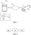
- FIG. 1is a diagram representing an exemplary color sensing system implementing a color sensing device.
- FIG. 2is a diagram representing a cloud-based color sensing system according to exemplary embodiments of the present disclosure.
- FIG. 3is a diagram representing relationships between components of a color sensing system according to exemplary embodiments of the present disclosure.
- FIG. 4is a flowchart representing an exemplary method for implementing a priori estimation in a color sensing system according to the present disclosure.
- FIG. 5is a flowchart representing an exemplary method for implementing an absolute adjustment in a color sensing system according to the present disclosure.
- FIG. 6is a flowchart representing an exemplary method for implementing a K-nearest neighbor (KNN) algorithm in a color sensing system according to the present disclosure.
- KNNK-nearest neighbor
- FIG. 7is a flowchart representing an exemplary method for implementing an Artificial Neural Network (ANN) algorithm in a color sensing system according to the present disclosure.
- ANNArtificial Neural Network
- FIG. 8is a flowchart representing an exemplary method for implementing a secondary adjustment in a color sensing system according to the present disclosure.
- FIG. 9is a flowchart representing an exemplary method for implementing a cloud service associated with in a color sensing system according to the present disclosure.
- FIG. 10is a flowchart representing an alternative exemplary method for implementing a cloud service associated with in a color sensing system according to the present disclosure.
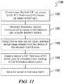
- FIG. 11is a flowchart representing an exemplary calibration method for a color sensing system according to the present disclosure.
- FIGS. 1-11a computer-implemented intelligent alignment system and for a color sensing device which initially obtains a raw sense value measured by the color sensing device according to the present disclosure may now be described in greater detail.
- a computer-implemented intelligent alignment system and for a color sensing devicewhich initially obtains a raw sense value measured by the color sensing device according to the present disclosure may now be described in greater detail.
- similar elements and featuresare given the same reference numerals and redundant description thereof may be omitted below.
- An exemplary color sensing system 10 as represented in FIG. 1may include without limitation a color sensing device 12 formed by a combination of a base module 14 and at least a color sensing module 16 , and a computer program product 20 .
- the program producti.e., program instructions
- the program productmay reside generally on a computer readable medium of a user computing device (e.g., typically a mobile computing device such as a smartphone or tablet computer, but also including a desktop computer, etc.) remote from the aforementioned modules or otherwise accessible by and executable from the mobile computing device.
- the program productmay be downloadable from a host server (not shown) to the user computing device in its entirety, or in various embodiments may be a distributed program product including one or more program modules executable from the user computing device 18 and one or more program modules executable from the host server via a communications network 26 .
- the user computing device 18may comprise a processor 24 configurable to execute program modules, and may further comprise storage 22 .
- the term “communications network” as used herein with respect to data communication between two or more parties or otherwise between communications network interfaces associated with two or more partiesmay refer to any one of, or a combination of any two or more of, telecommunications networks (whether wired, wireless, cellular or the like), a global network such as the Internet, local networks, network links, Internet Service Providers (ISP's), and intermediate communication interfaces.
- telecommunications networkswhether wired, wireless, cellular or the like
- a global networksuch as the Internet, local networks, network links, Internet Service Providers (ISP's), and intermediate communication interfaces.
- ISP'sInternet Service Providers
- a color sensing device 12 of the present disclosuremay be defined by the color sensing module 16 alone or a combination of the base 14 and color sensing modules 16 via direct coupling of the color sensing module 16 to the base module 14 .
- the base moduleenables remote communications to and from the color sensing module with respect to the user computing device 18 .
- the base modulemay further define a base, processing unit, communications interface and/or power supply for any one or more of a plurality of sensing modules that may be detachably coupled to the base module at any given time.
- the color-sensing module 16may be a ChromaTM sensor module selected from a family of sensor modules offered by Variable, Inc. for use with a base module (or host module), which may be a NODETM device also as offered by Variable, Inc.
- the color sensing module 16further comprises a CryptoAuthentication chip or an equivalent as known in the art, which enables restricting use of the color sensing module 16 with respect to the base module 14 or any other proprietary system as desired.
- This chipmay also further enable storage of unique calibration information for each color sensing device 12 .
- embodiments consistent with the present disclosuremay variously utilize a cloud client 210 and/or cloud service 220 communicatively connected to network 26 , as illustrated at FIG. 2 , in order to access, store, and/or transmit data within the spirit and scope of the disclosure.
- a color sensing device 12may function as a cloud client 210 and may submit data to cloud service 220 for processing.
- a cloud service 220may store parameters associated with cloud client 210 or may perform processing related to parameters associated with cloud client 210 which are transmitted to cloud client 210 for use in color calibration and/or processing.
- both the cloud client 210 and cloud service 220may, in various embodiments, perform the roles of either clients or servers depending upon a particular implementation.
- the base module 14may in one embodiment be a NODE unit as offered by Variable, Inc.
- the base module 14 in this embodimentis an intermediate hardware component with a microprocessor and communication peripherals that handle Bluetooth communication with a user device 18 such as a smartphone or the like.
- Different sensing modulesincluding for example Chroma, can be connected to the base module 14 and may be structurally interchangeable with each other while maintaining distinct sensing functions.
- the color sensing device 12may include a color sensing module 16 and a base module 14 having associated motion sensing functionality.
- a color sensing method of the present disclosuremay accordingly only be enabled when the base module verifies that the color sensing device is stationary and thereby assure more accurate color measurements.
- the color sensing device 12may include a color sensing module 16 and an air temperature sensing module (not shown) both interchangeably connectable to either of a plurality of connection ports on the base module 14 , wherein the color sensing system may have an enhanced color measurement method based further upon a sensed ambient temperature.
- the temperature sensing moduleis a Clima device as offered by Variable, Inc. which is further effective to sense barometric pressure, ambient light, humidity, etc., representative outputs for each of which may supplement color measurements or otherwise be displayed on the user device.
- a computer program product of a color sensing system 10 of the present disclosuremay comprise computer instructions residing on a non-transitory computer-readable medium in a computing device such as for example a smart phone or tablet computer.
- the computer program productmay reside in a non-transitory computer-readable medium such as a server system remote from the computing device but communicatively linked to the computing device such that execution of the computer program product directs the performance of a color sensing, storage and comparison method according to the present disclosure, at least part of which includes steps for generating a user interface on a display of the computing device and receiving user input regarding, e.g., various display parameters.
- the computer program productmay be or include the Chroma smartphone application as provided by Variable, Inc., which enables many unique features including base module (i.e., NODE) connectivity, color sensing, color display, color comparison, color information storage, history lookup, and others as listed in the sections below.
- base modulei.e., NODE
- FIG. 3illustrates relationships between components according to an exemplary embodiment of the present disclosure.
- matching tables 310may be associated with one or more batches 320 .
- Matching tables 310may comprise data correspondence information, such as conversion or mapping information between color spaces or reference data.
- Each batch 320may comprise at least one color sensing device 12 having an individual sensor calibration, and may, in one embodiment, be configured to group a plurality of color sensing devices 12 according to an associated ⁇ E value.
- a ⁇ E valueis a color difference standard which traditionally refers to a color space “distance” related to a perceived color difference when viewed by a human eye.
- each batch 320may be associated with an absolute adjustment 330 .
- this difficultymay be overcome by restructuring the problem into a supervised learning problem, for which a function approximation algorithm may be used.
- supervised learningis a branch of machine learning in which a learning algorithm is presented a set of inputs and the corresponding correct outputs. The algorithm may then “learn” the relationship between these inputs and outputs and produces a model that can be used to predict future unknown data based on the data it has been trained to learn. Therefore, the strategies presented herein may, in various embodiments, involve obtaining unadjusted color data and reference device data for a specially formulated set of colors. This data may then be used to create a model that approximates the function represented in Eq. 1. Transformed color readings after absolute adjustment may be referred to as adjusted color readings.
- the system illustrated by FIG. 3may include a Secondary Adjustment 340 .
- Secondary Adjustment 340may, in one embodiment, comprise a measurement surface adjustment.
- Accurate measurement of colorrequires that a color sensing device 12 illuminates a measurement surface with a known light source and captures the portion of this light reflecting off the surface.
- the reflection of this lightmay vary not only based on color, but also based on surface texture and translucency of the substrate. It is very likely that the desired reference device 350 may capture light from a rough surface texture differently from an unaligned color sensing device 12 .
- a Secondary Adjustment 340may be used in series after an Absolute Adjustment 330 . This allows the Absolute Adjustment 330 to make modifications needed to align a color sensing device 12 with the reference device 350 over the visible gamut and the Secondary Adjustment 340 to handle any sort of shift that may occur due to surface texture.
- Secondary Adjustment 340for surface textures, it is also possible in one exemplary embodiment to circumvent any true alignment, and to build a database of unadjusted color readings for a given color set. This may then be used to simply “match” unknown scans to the closest known color in the database.
- a Secondary Adjustment 340may comprise Artificial Neural Network (ANN) processing.
- ANN processingmay be implemented, for example, on a small set of different material types with less than 200 training examples per material, and in such implementation has proven to greatly improve the alignment between a learning device and the reference device 350 .
- the above-described method of performing Secondary Adjustment 340may be developed for a plurality of any material/surface types, using only a few training samples for each material/surface type.
- a color devicemay be calibrated by scanning a small known set of colors (e.g., 20-30) that is roughly representative of the standard color gamut.
- Scanned raw readingsmay be mapped to known tristimulus values in order to create a standard sense to tristimulus mapping for a color device. These mapped values may then be converted to a standard reference illuminant color space (e.g., D50 or D65) using chromatic adaptation from the measured reflectance curve of a color device's illuminant to D50/D65, for example by use of the Bradford method.
- calibrated device readings in a standard color spacemay be referred to as unadjusted color readings.
- Batchingmay use a representative “batching color set” that is greater than or equal to the number of colors in the initial a priori calibration color set and also represents the full color gamut.
- Devicesmay be grouped together based on a maximum allowed device-to-device ⁇ E for each color across the batching color set. With this, batches 320 of color sensing devices 12 may be created with known unit-to-unit consistency.
- representative color sensing device(s) 12 from the batchmay be scanned using any of a plurality of methods in order to maximize accuracy for all color sensing devices 12 in the batch 320 , for example, by means of Absolute Adjustment 330 described above.
- Embodiments consistent with the present disclosuremay include a designated color set that covers the visible color gamut uniformly using a reduced number of colors.
- the Variable 7300 training color setmay be used, which implements only 7383 colors. Uniformity of the color set over the visible spectrum increases a designated color set's effectiveness in building a set of supervised learning training data.
- a designated color setmay be realized in four general forms: a theoretical model, a printed representation of the theoretical model, and a digital representation of the printed model as measured by a reference device 350 , and a digital representation of the printed model as measured by a color sensing device 12 .
- the designated color sete.g., Variable 7300
- the designated color setas measured by a color sensing device 12 may be paired with the same designated color set as measured by a desired reference device 350 .
- raw sense values received from a color sensing device 12may be converted to tristimulus values, such as CIE XYZ values or the like.
- a color sensing device 12may be calibrated using a known set of colors.
- the known set of colorsmay include any of a subset of colors of the color gamut.
- the known set of colorsmay comprise the Variable 7300 color set or at least a portion thereof.
- Step S 403maps raw readings to known tristimulus values.
- the mapped valuesare converted to a standard reference illuminant color space.
- the standard illuminant color spacemay comprise, for example, the D50 and/or D65 illuminant color spaces, or the like.
- FIG. 5provides an exemplary implementation of an Absolute Adjustment process in accordance with the above-described Absolute Adjustment 330 .
- the processbegins at step S 501 , where devices are grouped based upon a maximum permissible ⁇ E for each color across a batching color set.
- steps S 502relationships are learned between inputs and output in order to produce a model for future unknown data.
- An unadjusted color readingis received as an input at step S 503 , and an adjusted color reading is generated at step S 504 according to the produced model.
- the entire supervised training set of raw scans and reference scansmay be stored in a database.
- a machine learning techniquefor example, a K Nearest Neighbor, Artificial Neural Network, or other machine learning technique may be used.
- KNNK Nearest Neighbor
- a K Nearest Neighbor (KNN) algorithmmay search through the database for the K nearest scans to the unadjusted color reading. The KNN algorithm may then return a weighted average of the K corresponding reference scans.
- the results of the KNN algorithmare extremely accurate for colors in or near the designated color set. However, this method loses accuracy when predicting colors that are not near a color in the designated color set.
- FIG. 6An exemplary process consistent with the above-noted KNN algorithm implementation is illustrated at FIG. 6 .
- raw scan data and reference scan dataare stored.
- a KNN algorithmis executed to search for K nearest scans to an unadjusted color reading.
- a weighted average of K reference scans associated with unadjusted color readingsis returned at step S 603 .
- a subset of the designated color spacemay be scanned to create a supervised learning training set.
- This setmay be used to train an Artificial Neural Network (ANN).
- ANNArtificial Neural Network
- An ANNis a machine learning method that is capable of estimating very complex functions present in the training set.
- the ANNmay be trained in one embodiment by using the standard gradient-descent backpropagation algorithm.
- the results of this methodare not as accurate as the lookup table for colors on or near the designated color set, but accuracy may be greatly improved for all other colors.
- the training set used to train the ANNcan be reduced tenfold without a major deterioration in performance.
- the ANNproves to do a better job providing a continuous representation of the color sensing device 12 's error when compared to the KNN method. It is also advantageous that the number of reference scans needed for this method is one tenth of the KNN method, which may greatly reduce production cost.
- FIG. 7An exemplary implementation of the above-described ANN algorithm is illustrated by FIG. 7 , which begins at step S 701 by training an ANN. At step S 702 an unadjusted color reading is received. A color is returned by the ANN algorithm based upon an ANN continuous representation associated with processed training data at step S 703 .
- FIG. 8provides an exemplary implementation of Secondary Adjustment 340 according to one embodiment of the present disclosure.
- Step S 801 of FIG. 8provides that a secondary ANN is developed according to different material types and/or surfaces.
- color data previously processed according to Absolute Adjustment 330is operated upon.
- step S 803a color is provided which has been adjusted based upon a material and/or surface type.
- a cloud-based systemmay allow for the above-noted techniques to be distributed to a large number of devices.
- a cloud servicemay scalably package all of the calibration, batching, adjustment methods, and advanced mathematics and allow the alignment methods to be accessed by an end user of the color sensing device 12 . Also, it may permit implementation of a relatively simple color “match” service that can be performed with unadjusted color readings or with fully aligned readings.
- a matching servicecan be created by simply obtaining a library of unadjusted CIE Standard color readings of the desired objects/colors to match.
- the systemUpon a request for the nearest match (a smallest ⁇ E may be used to represent color similarity as seen by the human eye) to a real-world scan, the system must only compare its unadjusted scan with the desired library of raw readings and return the identity of the nearest match.
- the data for this methodis represented by matching tables 310 of FIG. 3 .
- the above-described methodmay be effective for almost any type of color/surface texture combination, but has two potential weaknesses. First, it is missing the ability to give a reading that is accurately aligned to the reference device 350 . It is easy for the color sensing device 12 to recognize that it has “seen” a similar color before, and to give a user the information regarding that similar color, but the color sensing device 12 does not know how the reference device 350 will measure that color. Lastly, since this takes place before the Absolute Adjustment 330 , it requires that a library is created for each batch 320 of devices (see FIG. 3 ). This can be very expensive from a production perspective.
- a database according to this exemplary embodimentmay be utilized in two main ways, each naturally requiring some level of internet connectivity to access the cloud database.
- Bluetooth radio technologymay permit devices to interface with one or more internet connected client devices which may be configured to act as a cloud client 210 .
- a color sensing device 12may comprise onboard internet connectivity which permits the color sensing device 12 to act as its own cloud client 210 .
- a color sensing device 12may comprise onboard internet connectivity permitting the color sensing device to connect to an external device which functions as a cloud client 210 or a cloud service 220 .
- a cloud client 210may interact with a cloud service 220 in a plurality of manners.
- the cloud client 210may connect to a cloud service 220 .
- the color sensing device 12may be connected to an internet enabled device that will act as the cloud client 210 .
- the color sensing device 12may relay its unique ID to the cloud service 220 via the cloud client 210 .
- the cloud service 220may respond with alignment data that is unique to the color sensing device 12 .
- This informationmay be stored at the internet enabled device, where a software application may perform processing to utilize the alignment data and process referenced aligned color measurements. Alternatively, the information may be transmitted to the color sensing device 12 , which may perform processing to utilize the alignment data and referenced aligned color measurements.
- the aforementioned software application that interacts with the cloud service 220 and stores data on the client internet enabled devicemay be packaged as a software Application Programming Interface (API) and may be made available for use by applications and software developers. If new alignment methods are developed or more reference libraries are added to the cloud database, the cloud service 220 may permit seamless updates of the information stored in the client application, and the API may automatically detect and/or request updates upon internet connectivity or when internet connectivity is present. This allows the device to become “smarter” over its lifetime without the need for recalls or cumbersome device firmware updates.
- APIApplication Programming Interface
- all or a portion of alignment operationsmay be performed by cloud service 220 .
- cloud service 220Rather than relying on a cloud client 210 to perform alignment calculations, it can simply relay raw sensor readings and a unique device ID to the cloud service 220 and allow any or all of the adjustments to be performed remotely in the cloud. Though this requires internet connectivity to receive adjusted scans, this embodiment may be desirable for a number of reasons (e.g., connectivity, distributability, etc.).
- various functionality of their color sensing devices 12may be restricted (e.g., for security purposes).
- many raw sensor readingsmay be recorded at a single time, then a request that they be adjusted by many alignment methods at once may be received, the alignment methods may be performed in accordance with any future alignment methods. Allowing all calculations to be performed by the cloud service 220 may require internet connectivity, but also adds many freedoms from the perspective of an end user.
- FIG. 9provides an exemplary implementation of a cloud-based system in accordance with the present disclosure.
- a sensor 10is provided to client device(s) for example by a color sensing device 12 .
- a client devicemay comprise an internet connected device, a color sensing device 12 , or the like or may be a separate device in communication with a color sensing device 12 .
- a client devicemay request calibration data, for example from a cloud service 220 .
- response data and/or matching datamay be returned to the client device.
- a client devicemay perform adjustment operations corresponding to the response data and/or matching data at step S 904 .
- FIG. 10provides another exemplary implementation of a cloud-based system in accordance with the present disclosure.
- all alignmentmay be performed by cloud service 220 in the process illustrated by FIG. 10 .
- a color sensing device 12sends a raw sensor reading and a sensor 10 to a client device.
- the client devicesends the raw sensor data and the sensor 10 along with an adjustment type to cloud service 220 .
- the cloud servicemay perform operations corresponding to raw sensor reading, sensor 10 , and/or adjustment type.
- aligned color data and/or match datamay be returned to a client device.
- an exemplary color sensing methodmay include an algorithm for sensor calibration using a priori estimation. Thanks to the linearity of a color sensing chip used in various exemplary embodiments of the present disclosure (e.g., a Chroma color sensing module), one exemplary embodiment of an a priori sensor calibration algorithm 1100 as represented in FIG. 11 enables the sensor to detect the tristimulus coordinates of colors with an average accuracy of 0.6%.
- known MacBeth CIE Lab valuesmay be converted to CIE xyz Tristimulus (Xyz) values, which at this stage may be based on d50 light (step 1101 ). Chromatic adaptation of these values is performed (step 1102 ) by converting them to a reference light using a transformation method, for example a Bradford transform as is known in the art (e.g., by conversion to d65 reference light).
- the color sensing module of the present disclosurethen generates raw red, green and blue sensor measurements (step 1103 ) from a color rendition chart, for example a MacBeth ColorChecker or other color rendition chart used as a calibration target.
- the host systemmay generate a sensor to CIE Tristimulus (xyz) matrix (step 1104 ) which may be used for converting future output values from the color sensor into CIE Tristimulus values a priori.
- the generated tristimulus matrixmay be stored to a memory such as, for example, a CryptoAuthentication chip in the color sensing module (step 1105 ).
- the generated tristimulus matrixmay be stored using the cloud service 220 , as previously described and as illustrated at FIG. 2 .
- the process illustrated at FIG. 11may continue in accordance with the processes described herein and illustrated, for example, by FIGS. 4-10 .
- the usermay further select one or more of a plurality of lighting conditions, wherein the first and at least second color are displayed in accordance with the selected lighting condition, or only a first color may be displayed in accordance with a plurality of selected lighting conditions, etc.
- acts, events, or functions of any of the algorithms described hereincan be performed in a different sequence, can be added, merged, or left out altogether (e.g., not all described acts or events are necessary for the practice of the algorithm).
- acts or eventscan be performed concurrently, e.g., through multi-threaded processing, interrupt processing, or multiple processors or processor cores or on other parallel architectures, rather than sequentially.
- a machinesuch as a general purpose processor, a digital signal processor (DSP), an application specific integrated circuit (ASIC), a field programmable gate array (FPGA) or other programmable logic device, discrete gate or transistor logic, discrete hardware components, or any combination thereof designed to perform the functions described herein.
- DSPdigital signal processor
- ASICapplication specific integrated circuit
- FPGAfield programmable gate array
- a general purpose processorcan be a microprocessor, but in the alternative, the processor can be a controller, microcontroller, or state machine, combinations of the same, or the like.
- a processorcan also be implemented as a combination of computing devices, e.g., a combination of a DSP and a microprocessor, a plurality of microprocessors, one or more microprocessors in conjunction with a DSP core, or any other such configuration.
- a software modulecan reside in RAM memory, flash memory, ROM memory, EPROM memory, EEPROM memory, registers, hard disk, a removable disk, a CD-ROM, or any other form of computer-readable medium known in the art.
- An exemplary computer-readable mediumcan be coupled to the processor such that the processor can read information from, and write information to, the memory/storage medium.
- the mediumcan be integral to the processor.
- the processor and the mediumcan reside in an ASIC.
- the ASICcan reside in a user terminal.
- the processor and the mediumcan reside as discrete components in a user terminal.
Landscapes
- Physics & Mathematics (AREA)
- Spectroscopy & Molecular Physics (AREA)
- General Physics & Mathematics (AREA)
- Engineering & Computer Science (AREA)
- Theoretical Computer Science (AREA)
- Mathematical Physics (AREA)
- Biomedical Technology (AREA)
- General Engineering & Computer Science (AREA)
- Data Mining & Analysis (AREA)
- Evolutionary Computation (AREA)
- General Health & Medical Sciences (AREA)
- Molecular Biology (AREA)
- Computing Systems (AREA)
- Computational Linguistics (AREA)
- Biophysics (AREA)
- Artificial Intelligence (AREA)
- Software Systems (AREA)
- Life Sciences & Earth Sciences (AREA)
- Health & Medical Sciences (AREA)
- Human Computer Interaction (AREA)
- Spectrometry And Color Measurement (AREA)
Abstract
Description
SCANref=f(SCANdevice) (Eq. 1).
Claims (14)
Priority Applications (1)
| Application Number | Priority Date | Filing Date | Title |
|---|---|---|---|
| US16/224,027US10809129B2 (en) | 2015-05-01 | 2018-12-18 | Intelligent alignment system and method for color sensing devices |
Applications Claiming Priority (3)
| Application Number | Priority Date | Filing Date | Title |
|---|---|---|---|
| PCT/US2015/028861WO2016178653A1 (en) | 2015-05-01 | 2015-05-01 | Intelligent alignment system and method for color sensing devices |
| US201615032335A | 2016-04-27 | 2016-04-27 | |
| US16/224,027US10809129B2 (en) | 2015-05-01 | 2018-12-18 | Intelligent alignment system and method for color sensing devices |
Related Parent Applications (2)
| Application Number | Title | Priority Date | Filing Date |
|---|---|---|---|
| US15/032,335ContinuationUS10156477B2 (en) | 2015-05-01 | 2015-05-01 | Intelligent alignment system and method for color sensing devices |
| PCT/US2015/028861ContinuationWO2016178653A1 (en) | 2015-05-01 | 2015-05-01 | Intelligent alignment system and method for color sensing devices |
Publications (2)
| Publication Number | Publication Date |
|---|---|
| US20190120693A1 US20190120693A1 (en) | 2019-04-25 |
| US10809129B2true US10809129B2 (en) | 2020-10-20 |
Family
ID=57218012
Family Applications (2)
| Application Number | Title | Priority Date | Filing Date |
|---|---|---|---|
| US15/032,335ActiveUS10156477B2 (en) | 2015-05-01 | 2015-05-01 | Intelligent alignment system and method for color sensing devices |
| US16/224,027ActiveUS10809129B2 (en) | 2015-05-01 | 2018-12-18 | Intelligent alignment system and method for color sensing devices |
Family Applications Before (1)
| Application Number | Title | Priority Date | Filing Date |
|---|---|---|---|
| US15/032,335ActiveUS10156477B2 (en) | 2015-05-01 | 2015-05-01 | Intelligent alignment system and method for color sensing devices |
Country Status (4)
| Country | Link |
|---|---|
| US (2) | US10156477B2 (en) |
| EP (1) | EP3289322A4 (en) |
| CN (1) | CN107873079B (en) |
| WO (1) | WO2016178653A1 (en) |
Families Citing this family (9)
| Publication number | Priority date | Publication date | Assignee | Title |
|---|---|---|---|---|
| US10346710B2 (en) | 2016-09-29 | 2019-07-09 | Datacolor Inc. | Multi-agent training of a color identification neural network |
| US10692245B2 (en)* | 2017-07-11 | 2020-06-23 | Datacolor Inc. | Color identification in images |
| CN108333801B (en)* | 2018-01-15 | 2021-09-10 | 武汉精测电子集团股份有限公司 | System and method for collecting chromatic value of liquid crystal module |
| US10748304B2 (en) | 2018-03-08 | 2020-08-18 | Datacolor Inc. | Color search using a smartphone and a reference color chart |
| US10718669B2 (en) | 2018-09-12 | 2020-07-21 | Datacolor, Inc. | Re-calibrating color measurement instruments based on user-made color selections |
| US10502628B1 (en) | 2018-09-27 | 2019-12-10 | Datacolor Inc. | Inter-instrument variation correction |
| US10746599B2 (en)* | 2018-10-30 | 2020-08-18 | Variable, Inc. | System and method for spectral interpolation using multiple illumination sources |
| US11733099B2 (en) | 2019-10-30 | 2023-08-22 | Datacolor Inc. | System and method to calibrate color measurement devices |
| WO2023086747A1 (en) | 2021-11-10 | 2023-05-19 | Swimc Llc | System and method for tinting using low-resolution spectrophotometer |
Citations (50)
| Publication number | Priority date | Publication date | Assignee | Title |
|---|---|---|---|---|
| EP0525964A2 (en) | 1991-06-25 | 1993-02-03 | Scitex Corporation Ltd. | Apparatus and method for color calibration |
| US5725318A (en)* | 1995-10-17 | 1998-03-10 | Brother Kogyo Kabushiki Kaisha | Tape-shaped label printing device usable with ribbon cassettes having newly added colors |
| US6043909A (en)* | 1996-02-26 | 2000-03-28 | Imagicolor Corporation | System for distributing and controlling color reproduction at multiple sites |
| US20020122044A1 (en) | 2000-10-23 | 2002-09-05 | Sun Microsystems, Inc. | Multi-spectral color correction |
| US20020159066A1 (en) | 2001-04-27 | 2002-10-31 | International Business Machines Corporation | Portable colorimeter |
| US6480299B1 (en) | 1997-11-25 | 2002-11-12 | University Technology Corporation | Color printer characterization using optimization theory and neural networks |
| US20020184168A1 (en) | 2001-06-05 | 2002-12-05 | Mcclanahan Craig J. | System and method for determining acceptability of proposed color solution using an artificial intelligence based tolerance model |
| US6584435B2 (en) | 2001-08-30 | 2003-06-24 | Xerox Corporation | Systems and methods for determining spectra using dynamic karhunen-loeve algorithms with measurements from led color sensor |
| US6649416B1 (en) | 2000-02-18 | 2003-11-18 | Trustees Of Tufts College | Intelligent electro-optical sensor array and method for analyte detection |
| US20040141213A1 (en) | 2003-01-09 | 2004-07-22 | Larry Kleiman | System for capturing graphical images using hyperspectral illumination |
| US20050018191A1 (en) | 2001-10-04 | 2005-01-27 | Luo Ming Ronnier | Apparatus and method for measuring colour |
| US20050151974A1 (en) | 2004-01-14 | 2005-07-14 | Xerox Corporation | Methods for automated uniformity assessment and modification of image non-uniformities |
| US20050275912A1 (en) | 2004-06-15 | 2005-12-15 | Yung-Chih Chen | Method and apparatus for calibrating color temperature of color display devices |
| KR20070011671A (en) | 2005-07-21 | 2007-01-25 | (주)더리즈 | Method for manufacturing gallium nitride compound semiconductor device having a compliant substrate |
| US20070035554A1 (en) | 2005-08-09 | 2007-02-15 | Basf Corporation | Method of visualizing a color deviation |
| US7283238B2 (en) | 2002-08-21 | 2007-10-16 | Kokninklijke Philips Electronics N.V. | Method and apparatus for matching colours |
| CN101055206A (en) | 2007-05-25 | 2007-10-17 | 南开大学 | Interference-free color sampling device of machine vision system |
| US20080013077A1 (en) | 2006-04-10 | 2008-01-17 | Orelli Adrian V | Handheld colour measurement device |
| US7333963B2 (en)* | 2004-10-07 | 2008-02-19 | Bernard Widrow | Cognitive memory and auto-associative neural network based search engine for computer and network located images and photographs |
| US20080136836A1 (en) | 1997-06-27 | 2008-06-12 | Edge Christopher J | Method for mapping colors between imaging systems and method therefor |
| US20080259336A1 (en) | 2004-01-23 | 2008-10-23 | Olympus Corporation | Image processing system and camera |
| US7557925B2 (en) | 2005-08-15 | 2009-07-07 | X-Rite, Inc. | Optical instrument and parts thereof for optimally defining light pathways |
| US20100155608A1 (en)* | 2008-12-19 | 2010-06-24 | Utah State University | Optimized case specific spect sampling |
| US20100295942A1 (en) | 2009-05-19 | 2010-11-25 | Cubic Corporation | Method and apparatus for measuring weapon pointing angles |
| US20110050892A1 (en) | 2008-04-23 | 2011-03-03 | Oliver ZIND | Image recording and color measuring system |
| US7944561B2 (en) | 2005-04-25 | 2011-05-17 | X-Rite, Inc. | Measuring an appearance property of a surface using a bidirectional reflectance distribution function |
| US8008613B2 (en) | 2009-05-05 | 2011-08-30 | Apple Inc. | Light sensing device having a color sensor and a clear sensor for infrared rejection |
| US20110215997A1 (en) | 2010-03-03 | 2011-09-08 | Samsung Electronics Co. Ltd. | Method and apparatus for providing function of portable terminal using color sensor |
| US20120014571A1 (en)* | 2010-07-13 | 2012-01-19 | Wong Victor C | Dental shade mapping |
| US8139220B2 (en) | 2008-09-16 | 2012-03-20 | X-Rite, Inc. | Point-of purchase (POP) spectrophotometer for open-view measurement of a color sample |
| JP2012065192A (en) | 2010-09-16 | 2012-03-29 | Dic Corp | Device, method and program for assisting in color selection |
| US20120129269A1 (en) | 2009-03-20 | 2012-05-24 | Nanolambda, Inc. | Nano-optic filter array based sensor |
| US8237138B2 (en) | 2005-09-08 | 2012-08-07 | X-Rite, Inc. | Systems and method for optical scatter imaging of latent image plates |
| US8271021B2 (en) | 2009-06-19 | 2012-09-18 | Lg Electronics Inc. | Mobile terminal and method of performing functions using the same |
| US8280126B2 (en)* | 2005-10-24 | 2012-10-02 | Synarc Inc. | Cartilage curvature |
| US20120250020A1 (en) | 2011-04-01 | 2012-10-04 | X-Rite Europe Gmbh | Hand-held color measurement device |
| US20120331546A1 (en)* | 2011-06-22 | 2012-12-27 | Falkenburg David R | Intelligent stylus |
| US20130042295A1 (en) | 2011-08-10 | 2013-02-14 | Charles C. Kelly | Method and apparatus for providing a secure virtual environment on a mobile device |
| US20130050703A1 (en) | 2011-08-31 | 2013-02-28 | Colman Shannon | Method and apparatus for calibrating a color measurement device |
| US20140022410A1 (en)* | 2011-12-28 | 2014-01-23 | Dolby Laboratories Licensing Corporation | Spectral Synthesis for Image Capture Device Processing |
| US20140111807A1 (en) | 2012-10-23 | 2014-04-24 | Apple Inc. | High accuracy imaging colorimeter by special designed pattern closed-loop calibration assisted by spectrograph |
| WO2014071302A1 (en) | 2012-11-02 | 2014-05-08 | Variable, Inc. | Computer-implemented system and method for color sensing, storage and comparison |
| US20140247469A1 (en)* | 2013-03-01 | 2014-09-04 | Xerox Corporation | Standardized multi-intent color control architecture |
| US9070192B1 (en)* | 2007-05-15 | 2015-06-30 | Vision Interface Technologies, LLC | Implementing rich color transition curve tracking for applications |
| US20150215312A1 (en) | 2013-09-16 | 2015-07-30 | Clutch Authentication Systems, Llc | System and method for secure single or multi-factor authentication |
| US9111350B1 (en)* | 2012-02-10 | 2015-08-18 | Google Inc. | Conversion of monoscopic visual content to stereoscopic 3D |
| US20160048739A1 (en) | 2014-08-15 | 2016-02-18 | Scanadu Incorporated | Precision luxmeter methods for digital cameras to quantify colors in uncontrolled lighting environments |
| US20160187199A1 (en)* | 2014-08-26 | 2016-06-30 | Digimarc Corporation | Sensor-synchronized spectrally-structured-light imaging |
| US20160253466A1 (en)* | 2013-10-10 | 2016-09-01 | Board Of Regents, The University Of Texas System | Systems and methods for quantitative analysis of histopathology images using multiclassifier ensemble schemes |
| US9593982B2 (en)* | 2012-05-21 | 2017-03-14 | Digimarc Corporation | Sensor-synchronized spectrally-structured-light imaging |
Family Cites Families (3)
| Publication number | Priority date | Publication date | Assignee | Title |
|---|---|---|---|---|
| KR20070111671A (en) | 2006-05-18 | 2007-11-22 | 심현섭 | Color measurement device using reflected light and its control method |
| US20110075146A1 (en) | 2009-09-29 | 2011-03-31 | Nathan Moroney | Color measurement device |
| JP6375557B2 (en)* | 2013-09-19 | 2018-08-22 | ロレアル ソシエテ アノニム | System and method for measuring and categorizing surface colors and spectra |
- 2015
- 2015-05-01CNCN201580081392.1Apatent/CN107873079B/enactiveActive
- 2015-05-01WOPCT/US2015/028861patent/WO2016178653A1/ennot_activeCeased
- 2015-05-01USUS15/032,335patent/US10156477B2/enactiveActive
- 2015-05-01EPEP15891344.2Apatent/EP3289322A4/enactivePending
- 2018
- 2018-12-18USUS16/224,027patent/US10809129B2/enactiveActive
Patent Citations (52)
| Publication number | Priority date | Publication date | Assignee | Title |
|---|---|---|---|---|
| EP0525964A2 (en) | 1991-06-25 | 1993-02-03 | Scitex Corporation Ltd. | Apparatus and method for color calibration |
| US5725318A (en)* | 1995-10-17 | 1998-03-10 | Brother Kogyo Kabushiki Kaisha | Tape-shaped label printing device usable with ribbon cassettes having newly added colors |
| US6043909A (en)* | 1996-02-26 | 2000-03-28 | Imagicolor Corporation | System for distributing and controlling color reproduction at multiple sites |
| US20080136836A1 (en) | 1997-06-27 | 2008-06-12 | Edge Christopher J | Method for mapping colors between imaging systems and method therefor |
| US6480299B1 (en) | 1997-11-25 | 2002-11-12 | University Technology Corporation | Color printer characterization using optimization theory and neural networks |
| US6649416B1 (en) | 2000-02-18 | 2003-11-18 | Trustees Of Tufts College | Intelligent electro-optical sensor array and method for analyte detection |
| US20020122044A1 (en) | 2000-10-23 | 2002-09-05 | Sun Microsystems, Inc. | Multi-spectral color correction |
| US20020159066A1 (en) | 2001-04-27 | 2002-10-31 | International Business Machines Corporation | Portable colorimeter |
| US20020184168A1 (en) | 2001-06-05 | 2002-12-05 | Mcclanahan Craig J. | System and method for determining acceptability of proposed color solution using an artificial intelligence based tolerance model |
| US6584435B2 (en) | 2001-08-30 | 2003-06-24 | Xerox Corporation | Systems and methods for determining spectra using dynamic karhunen-loeve algorithms with measurements from led color sensor |
| US20050018191A1 (en) | 2001-10-04 | 2005-01-27 | Luo Ming Ronnier | Apparatus and method for measuring colour |
| US7283238B2 (en) | 2002-08-21 | 2007-10-16 | Kokninklijke Philips Electronics N.V. | Method and apparatus for matching colours |
| US20040141213A1 (en) | 2003-01-09 | 2004-07-22 | Larry Kleiman | System for capturing graphical images using hyperspectral illumination |
| US20050151974A1 (en) | 2004-01-14 | 2005-07-14 | Xerox Corporation | Methods for automated uniformity assessment and modification of image non-uniformities |
| US20080259336A1 (en) | 2004-01-23 | 2008-10-23 | Olympus Corporation | Image processing system and camera |
| US20050275912A1 (en) | 2004-06-15 | 2005-12-15 | Yung-Chih Chen | Method and apparatus for calibrating color temperature of color display devices |
| US7333963B2 (en)* | 2004-10-07 | 2008-02-19 | Bernard Widrow | Cognitive memory and auto-associative neural network based search engine for computer and network located images and photographs |
| US7944561B2 (en) | 2005-04-25 | 2011-05-17 | X-Rite, Inc. | Measuring an appearance property of a surface using a bidirectional reflectance distribution function |
| KR20070011671A (en) | 2005-07-21 | 2007-01-25 | (주)더리즈 | Method for manufacturing gallium nitride compound semiconductor device having a compliant substrate |
| US20070035554A1 (en) | 2005-08-09 | 2007-02-15 | Basf Corporation | Method of visualizing a color deviation |
| US7557925B2 (en) | 2005-08-15 | 2009-07-07 | X-Rite, Inc. | Optical instrument and parts thereof for optimally defining light pathways |
| US8237138B2 (en) | 2005-09-08 | 2012-08-07 | X-Rite, Inc. | Systems and method for optical scatter imaging of latent image plates |
| US8280126B2 (en)* | 2005-10-24 | 2012-10-02 | Synarc Inc. | Cartilage curvature |
| US20080013077A1 (en) | 2006-04-10 | 2008-01-17 | Orelli Adrian V | Handheld colour measurement device |
| US9070192B1 (en)* | 2007-05-15 | 2015-06-30 | Vision Interface Technologies, LLC | Implementing rich color transition curve tracking for applications |
| CN101055206A (en) | 2007-05-25 | 2007-10-17 | 南开大学 | Interference-free color sampling device of machine vision system |
| US20110050892A1 (en) | 2008-04-23 | 2011-03-03 | Oliver ZIND | Image recording and color measuring system |
| US8139220B2 (en) | 2008-09-16 | 2012-03-20 | X-Rite, Inc. | Point-of purchase (POP) spectrophotometer for open-view measurement of a color sample |
| US20100155608A1 (en)* | 2008-12-19 | 2010-06-24 | Utah State University | Optimized case specific spect sampling |
| US20120129269A1 (en) | 2009-03-20 | 2012-05-24 | Nanolambda, Inc. | Nano-optic filter array based sensor |
| US8008613B2 (en) | 2009-05-05 | 2011-08-30 | Apple Inc. | Light sensing device having a color sensor and a clear sensor for infrared rejection |
| US20100295942A1 (en) | 2009-05-19 | 2010-11-25 | Cubic Corporation | Method and apparatus for measuring weapon pointing angles |
| US8271021B2 (en) | 2009-06-19 | 2012-09-18 | Lg Electronics Inc. | Mobile terminal and method of performing functions using the same |
| CN102193628A (en) | 2010-03-03 | 2011-09-21 | 三星电子株式会社 | Method and apparatus for providing function of portable terminal using color sensor |
| US20110215997A1 (en) | 2010-03-03 | 2011-09-08 | Samsung Electronics Co. Ltd. | Method and apparatus for providing function of portable terminal using color sensor |
| US20120014571A1 (en)* | 2010-07-13 | 2012-01-19 | Wong Victor C | Dental shade mapping |
| JP2012065192A (en) | 2010-09-16 | 2012-03-29 | Dic Corp | Device, method and program for assisting in color selection |
| US20120250020A1 (en) | 2011-04-01 | 2012-10-04 | X-Rite Europe Gmbh | Hand-held color measurement device |
| US20120331546A1 (en)* | 2011-06-22 | 2012-12-27 | Falkenburg David R | Intelligent stylus |
| US20130042295A1 (en) | 2011-08-10 | 2013-02-14 | Charles C. Kelly | Method and apparatus for providing a secure virtual environment on a mobile device |
| US20130050703A1 (en) | 2011-08-31 | 2013-02-28 | Colman Shannon | Method and apparatus for calibrating a color measurement device |
| US20140022410A1 (en)* | 2011-12-28 | 2014-01-23 | Dolby Laboratories Licensing Corporation | Spectral Synthesis for Image Capture Device Processing |
| US9111350B1 (en)* | 2012-02-10 | 2015-08-18 | Google Inc. | Conversion of monoscopic visual content to stereoscopic 3D |
| US9593982B2 (en)* | 2012-05-21 | 2017-03-14 | Digimarc Corporation | Sensor-synchronized spectrally-structured-light imaging |
| US20140111807A1 (en) | 2012-10-23 | 2014-04-24 | Apple Inc. | High accuracy imaging colorimeter by special designed pattern closed-loop calibration assisted by spectrograph |
| WO2014071302A1 (en) | 2012-11-02 | 2014-05-08 | Variable, Inc. | Computer-implemented system and method for color sensing, storage and comparison |
| US20140247469A1 (en)* | 2013-03-01 | 2014-09-04 | Xerox Corporation | Standardized multi-intent color control architecture |
| US20150215312A1 (en) | 2013-09-16 | 2015-07-30 | Clutch Authentication Systems, Llc | System and method for secure single or multi-factor authentication |
| US20160253466A1 (en)* | 2013-10-10 | 2016-09-01 | Board Of Regents, The University Of Texas System | Systems and methods for quantitative analysis of histopathology images using multiclassifier ensemble schemes |
| US20160048739A1 (en) | 2014-08-15 | 2016-02-18 | Scanadu Incorporated | Precision luxmeter methods for digital cameras to quantify colors in uncontrolled lighting environments |
| US20160187199A1 (en)* | 2014-08-26 | 2016-06-30 | Digimarc Corporation | Sensor-synchronized spectrally-structured-light imaging |
| US10113910B2 (en)* | 2014-08-26 | 2018-10-30 | Digimarc Corporation | Sensor-synchronized spectrally-structured-light imaging |
Non-Patent Citations (8)
| Title |
|---|
| Brian Heater: Node Modular iOS sensor Hands-On, Oct. 20, 2012, XP002763666, 6 pp. retrieved from the Internet on Oct. 31, 2016. |
| European Search Report for corresponding application No. EP 15 89 1344, dated Aug. 17, 2018, 10 pp. |
| European Supplemental Search Report for application No. EP 13 85 0063, dated Apr. 11, 2017. |
| http://spyder.datacolor.com/portfolio-view/spyder4elite/ Copy obtained from https://archive.org/web/as it appered on Apr. 7, 2012. |
| http://www.emxinc.com/industrial.html (accessed Jul. 27, 2015). |
| http://www.hitechnic.com/cgi-bin/commece.cgi?preadd=action&key-NC01038 (available Jul. 27, 2015). |
| Nektarios A. Valous et al: Colour calibration of a laboratory computer vision system for quality evaluation of pre-sliced hams, FRCFT Group, Biosystems Engineering, University College Dublin, Natonal University of Ireland, Belfield, Dublin 4, Ireland Ashtown Food Research Centre, Teagasc, Dublin 15, Ireland. |
| State Intellectual Property Office, P.R. China: First Office Action, dated May 3, 2016 in re: Patent Application No. 2013800624943.0, filed Nov. 4, 2013. |
Also Published As
| Publication number | Publication date |
|---|---|
| EP3289322A4 (en) | 2018-09-26 |
| WO2016178653A1 (en) | 2016-11-10 |
| CN107873079B (en) | 2019-08-02 |
| CN107873079A (en) | 2018-04-03 |
| US20170131147A1 (en) | 2017-05-11 |
| EP3289322A1 (en) | 2018-03-07 |
| US10156477B2 (en) | 2018-12-18 |
| US20190120693A1 (en) | 2019-04-25 |
Similar Documents
| Publication | Publication Date | Title |
|---|---|---|
| US10809129B2 (en) | Intelligent alignment system and method for color sensing devices | |
| US10484654B2 (en) | Color sensing system and method for sensing, displaying and comparing colors across selectable lighting conditions | |
| US10746599B2 (en) | System and method for spectral interpolation using multiple illumination sources | |
| CN106605400B (en) | Digital system and method for paint color matching | |
| CN114402379A (en) | Color calibration of display modules using a reduced number of display characteristic measurements | |
| JP2019020311A (en) | Color measurement method and color measurement device | |
| US10928251B2 (en) | Inter-instrument variation correction | |
| US11733099B2 (en) | System and method to calibrate color measurement devices | |
| CN104813148B (en) | Method and device for adjusting measured values of a color measuring instrument | |
| US10194035B2 (en) | Imager calibration via modeled responses to importance-weighted color sample data | |
| CN114174784B (en) | Method and system for quantifying spectral similarity between a sample color and a target color | |
| US20220276152A1 (en) | Method and system for matching and adjusting pigmentation of a sample coating to a target coating | |
| WO2017094559A1 (en) | Reflection-characteristic measurement system | |
| CN107340296B (en) | Variation export device, Variation export system, and known color bodies | |
| JP5097927B2 (en) | Color conversion matrix calculation method | |
| US11582398B2 (en) | Calibrating color measurement devices | |
| CN110907036B (en) | Non-contact color measurement method | |
| US9424801B2 (en) | Display control device, non-transitory computer readable medium storing display control program, and color value data structure | |
| Smith et al. | Visual Display Calibration: An Analysis of Efficacy in Color Management |
Legal Events
| Date | Code | Title | Description |
|---|---|---|---|
| AS | Assignment | Owner name:VARIABLE, INC., TENNESSEE Free format text:ASSIGNMENT OF ASSIGNORS INTEREST;ASSIGNORS:YU, GEORGE YANG;TEMPLE, ANDREW RICHARD;MCGEHEE, JEFF;REEL/FRAME:047808/0771 Effective date:20150506 | |
| FEPP | Fee payment procedure | Free format text:ENTITY STATUS SET TO UNDISCOUNTED (ORIGINAL EVENT CODE: BIG.); ENTITY STATUS OF PATENT OWNER: SMALL ENTITY | |
| FEPP | Fee payment procedure | Free format text:ENTITY STATUS SET TO SMALL (ORIGINAL EVENT CODE: SMAL); ENTITY STATUS OF PATENT OWNER: SMALL ENTITY | |
| STPP | Information on status: patent application and granting procedure in general | Free format text:DOCKETED NEW CASE - READY FOR EXAMINATION | |
| STPP | Information on status: patent application and granting procedure in general | Free format text:NON FINAL ACTION MAILED | |
| STPP | Information on status: patent application and granting procedure in general | Free format text:RESPONSE TO NON-FINAL OFFICE ACTION ENTERED AND FORWARDED TO EXAMINER | |
| STPP | Information on status: patent application and granting procedure in general | Free format text:FINAL REJECTION MAILED | |
| STPP | Information on status: patent application and granting procedure in general | Free format text:NON FINAL ACTION MAILED | |
| STPP | Information on status: patent application and granting procedure in general | Free format text:NOTICE OF ALLOWANCE MAILED -- APPLICATION RECEIVED IN OFFICE OF PUBLICATIONS | |
| STCF | Information on status: patent grant | Free format text:PATENTED CASE | |
| FEPP | Fee payment procedure | Free format text:MAINTENANCE FEE REMINDER MAILED (ORIGINAL EVENT CODE: REM.); ENTITY STATUS OF PATENT OWNER: SMALL ENTITY | |
| FEPP | Fee payment procedure | Free format text:SURCHARGE FOR LATE PAYMENT, SMALL ENTITY (ORIGINAL EVENT CODE: M2554); ENTITY STATUS OF PATENT OWNER: SMALL ENTITY | |
| MAFP | Maintenance fee payment | Free format text:PAYMENT OF MAINTENANCE FEE, 4TH YR, SMALL ENTITY (ORIGINAL EVENT CODE: M2551); ENTITY STATUS OF PATENT OWNER: SMALL ENTITY Year of fee payment:4 |