US10808921B2 - Mountable fixture with sensor activated lighting - Google Patents
Mountable fixture with sensor activated lightingDownload PDFInfo
- Publication number
- US10808921B2 US10808921B2US15/486,773US201715486773AUS10808921B2US 10808921 B2US10808921 B2US 10808921B2US 201715486773 AUS201715486773 AUS 201715486773AUS 10808921 B2US10808921 B2US 10808921B2
- Authority
- US
- United States
- Prior art keywords
- fixture
- hub body
- light
- mounting plate
- sensor
- Prior art date
- Legal status (The legal status is an assumption and is not a legal conclusion. Google has not performed a legal analysis and makes no representation as to the accuracy of the status listed.)
- Active, expires
Links
Images


Classifications
- F—MECHANICAL ENGINEERING; LIGHTING; HEATING; WEAPONS; BLASTING
- F21—LIGHTING
- F21V—FUNCTIONAL FEATURES OR DETAILS OF LIGHTING DEVICES OR SYSTEMS THEREOF; STRUCTURAL COMBINATIONS OF LIGHTING DEVICES WITH OTHER ARTICLES, NOT OTHERWISE PROVIDED FOR
- F21V33/00—Structural combinations of lighting devices with other articles, not otherwise provided for
- F21V33/0004—Personal or domestic articles
- F21V33/004—Sanitary equipment, e.g. mirrors, showers, toilet seats or paper dispensers
- A—HUMAN NECESSITIES
- A47—FURNITURE; DOMESTIC ARTICLES OR APPLIANCES; COFFEE MILLS; SPICE MILLS; SUCTION CLEANERS IN GENERAL
- A47K—SANITARY EQUIPMENT NOT OTHERWISE PROVIDED FOR; TOILET ACCESSORIES
- A47K10/00—Body-drying implements; Toilet paper; Holders therefor
- A47K10/04—Towel racks; Towel rails; Towel rods; Towel rolls, e.g. rotatable
- F—MECHANICAL ENGINEERING; LIGHTING; HEATING; WEAPONS; BLASTING
- F21—LIGHTING
- F21V—FUNCTIONAL FEATURES OR DETAILS OF LIGHTING DEVICES OR SYSTEMS THEREOF; STRUCTURAL COMBINATIONS OF LIGHTING DEVICES WITH OTHER ARTICLES, NOT OTHERWISE PROVIDED FOR
- F21V23/00—Arrangement of electric circuit elements in or on lighting devices
- F21V23/04—Arrangement of electric circuit elements in or on lighting devices the elements being switches
- F21V23/0442—Arrangement of electric circuit elements in or on lighting devices the elements being switches activated by means of a sensor, e.g. motion or photodetectors
- F21V23/0464—Arrangement of electric circuit elements in or on lighting devices the elements being switches activated by means of a sensor, e.g. motion or photodetectors the sensor sensing the level of ambient illumination, e.g. dawn or dusk sensors
- F—MECHANICAL ENGINEERING; LIGHTING; HEATING; WEAPONS; BLASTING
- F21—LIGHTING
- F21V—FUNCTIONAL FEATURES OR DETAILS OF LIGHTING DEVICES OR SYSTEMS THEREOF; STRUCTURAL COMBINATIONS OF LIGHTING DEVICES WITH OTHER ARTICLES, NOT OTHERWISE PROVIDED FOR
- F21V23/00—Arrangement of electric circuit elements in or on lighting devices
- F21V23/04—Arrangement of electric circuit elements in or on lighting devices the elements being switches
- F21V23/0442—Arrangement of electric circuit elements in or on lighting devices the elements being switches activated by means of a sensor, e.g. motion or photodetectors
- F21V23/0471—Arrangement of electric circuit elements in or on lighting devices the elements being switches activated by means of a sensor, e.g. motion or photodetectors the sensor detecting the proximity, the presence or the movement of an object or a person
- Y—GENERAL TAGGING OF NEW TECHNOLOGICAL DEVELOPMENTS; GENERAL TAGGING OF CROSS-SECTIONAL TECHNOLOGIES SPANNING OVER SEVERAL SECTIONS OF THE IPC; TECHNICAL SUBJECTS COVERED BY FORMER USPC CROSS-REFERENCE ART COLLECTIONS [XRACs] AND DIGESTS
- Y02—TECHNOLOGIES OR APPLICATIONS FOR MITIGATION OR ADAPTATION AGAINST CLIMATE CHANGE
- Y02B—CLIMATE CHANGE MITIGATION TECHNOLOGIES RELATED TO BUILDINGS, e.g. HOUSING, HOUSE APPLIANCES OR RELATED END-USER APPLICATIONS
- Y02B20/00—Energy efficient lighting technologies, e.g. halogen lamps or gas discharge lamps
- Y02B20/40—Control techniques providing energy savings, e.g. smart controller or presence detection
Definitions
- the present disclosurerelates generally to home fixtures or accessories.
- the present disclosurerelates to a fixture that incorporates an illumination device to provide illumination to an area surrounding the fixture.
- Standard fixturesare typically constructed out of materials and finishes that permit the fixture to withstanding daily usage, and often fixtures are coordinated to have similar materials and designs within a designated area.
- Such fixturestypically have a design that is part aesthetic and part functional.
- the fixturemay be constructed out of opaque materials, such as metal or thick plastic, and may be affixed to a wall or other similar surface within a room in which a user may utilize items retained on the fixture.
- Certain types of fixturessuch as a towel ring, are configured to maintain useful items (e.g., a towel) in close proximity to where a user may need it, for example, in a bathroom or near a sink.
- Such fixturesmay be used in variant lighting conditions as well, for example, at night or when a room is in a darkened condition.
- usersmay be unable to see or detect the fixture, or any items located on or retrained by the fixture, in low level lighting conditions.
- a usermay not be able to detect items and objects near the fixture in such low level lighting conditions. Accordingly, there is a need for a means to provide illumination to an area surrounding a fixture when the ambient light is in a low level condition or there is no ambient light surrounding the fixture.
- a fixtureincludes a hub body that is configured about a hub axis and formed to include a cavity at least partially defined by the hub body.
- the hub bodyincludes a first end and a second end, with an opening extending through the second end.
- the hub bodyis comprised of a non-transparent material.
- the fixturefurther includes a mounting plate configured to be secured to the second end of the hub body and may extend within the opening of the second end.
- the mounting plateis configured to secure the hub body to an external surface upon which the fixture is secured.
- the mounting plateis comprised of translucent material and includes an outer annular surface through which light can be transmitted.
- the fixturefurther includes a system of electronic components including a sensor system, a controller, and a light generating unit.
- the light generating unitincludes at least one light.
- the systemis contained within the cavity of the hub body, and the controller is configured to generate a light beam from the light based on input received from the sensor system.
- the sensor systemincludes both a motion detector sensor and an ambient light sensor that can detect and transmit information regarding the area surrounding the fixture.
- FIG. 1is a perspective view of an example of an illuminating towel fixture according to an exemplary embodiment of the disclosure
- FIG. 2is a cross-sectional view of an accessory hub of the fixture of FIG. 1 ;
- FIG. 3is a an exploded view of the accessory hub of FIG. 2 ;
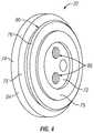
- FIG. 4is a front perspective view of a mounting plate of the accessory hub of the fixture of FIG. 1 ;
- FIG. 5is a simplified flowchart showing an example operation of an illuminating fixture according to an embodiment of the disclosure.
- references in the specification to “one embodiment,” “an embodiment,” “an illustrative embodiment,” etc.,indicate that the embodiment described may include a particular feature, structure, or characteristic, but every embodiment may or may not necessarily include that particular feature, structure, or characteristic. Moreover, such phrases are not necessarily referring to the same embodiment. Further, when a particular feature, structure, or characteristic is described in connection with an embodiment, it is submitted that it is within the knowledge of one skilled in the art to affect such feature, structure, or characteristic in connection with other embodiments whether or not explicitly described.
- FIG. 1shows an exemplary illuminating fixture 10 , namely a towel fixture, according to an embodiment of this disclosure.
- a towel fixturefor purposes of example, the method and apparatus for illuminating described herein could be implemented in any type of fixture, including other types of towel fixtures, paper fixtures/holders, hooks, pulls, handles, shelves, brackets and/or mounting hardware.
- the fixture 10includes a fixture or accessory hub 12 and a towel holder 14 coupled to the accessory hub 12 .
- the accessory hub 12is configured to be mounted or affixed to a wall or other surface (not shown) within a room so as to provide a user with ease of access to a towel (not shown) or other object retained on or within the towel holder 14 connected to the accessory hub 12 .
- the towel holder 14may be comprised of a ring or annularly-shaped bar 15 , wherein the towel or similar item is retained within an opening 16 formed in the holder 14 , the opening 16 circumscribed by the bar 15 .
- Other forms and shapes of a towel holder 14are envisioned within the scope of this disclosure. Further, other means for retaining a towel or similar items are generally known in the art.
- the fixture hub 12includes a hub body 20 , a mounting plate 22 that may be coupled to the hub body 20 , and a system 24 of electronic components and sensors generally housed in a cavity 26 of the hub body 20 .
- the hub body 20includes one or more retainers 28 ( FIG. 2 ) that permit the towel holder 14 to be coupled to the hub body 20 .
- a first end 17 of the bar 15may be configured to be received on a first retainer 28 a
- a second end 19 of the bar 15 of the towel holder 14may be configured to be received on a second retainer 28 b , as illustrated in FIG. 2 .
- retainers 28 a and 28 bmay be received within apertures 21 and 23 formed in the first and second ends 17 and 19 of the bar 15 , and the bar 15 may be rigid enough to be maintained securely on the retainers 28 a and 28 b .
- Other forms of attachment of the towel bar 14are envisioned within the scope of this disclosure.
- the hub body 20includes a first end 30 , a second end 32 , an outer surface 34 extending between the first and second ends 30 and 32 , and an inner surface 36 extending between the first and second ends 30 and 32 .
- the hub body 20may be positioned about a hub axis H, as illustrated in FIGS. 2-3 .
- the inner surface 36 of the hub body 20generally defines the cavity 26 of the hub body 20 .
- An exemplary embodiment of the hub body 20is a hub body having a generally annular or circular cross-sectional shape (for a cross-section taken at points along a length L of the hub body 20 ) as illustrated in FIGS.
- the hub body 20may have varying diameter sizes at various points along the length L of the hub body 20 that may be configured to provide aesthetic appeal or visual intrigue for the fixture 10 . It is envisioned that the hub body 20 may be formed of metal, plastic or any other suitable material capable of being utilized in a manner disclosed herein. As illustrated in FIGS. 1-3 , the retainers 28 may be integrally formed as part of the outer surface 34 , or may be coupled to the outer surface 34 , to retain the towel holder 14 to the hub body 20 .
- the cavity 26 of the hub body 20may be accessed via an opening 38 formed in the second end 32 of the hub body 20 .
- the opening 38is circumscribed by an annular lip 33 of the second end 32 .
- the annular lip 33may be formed to extend annularly inward into the opening 38 from the second end 32 of the hub body 20 .
- the mounting plate 22may be configured to be received within the opening 38 formed in the second end 32 in order to mount the hub body 20 to a wall or other surface (not shown) via the mounting plate 22 .
- the electrical system 24may be positioned within the cavity 26 before the mounting plate 22 is secured to the hub body 20 to be retained therein.
- the mounting plate 22is configured to be removable from the hub body 20 in order to permit access to the electrical system 24 , for instance, to replace components of the electrical system if necessary.
- FIGS. 2-4illustrate an exemplary embodiment of the mounting plate 22 .
- the mounting plate 22comprises a mounting body 72 , an annular mounting ring 74 coupled to the mounting body 72 , and an annular retainer 76 also coupled to the mounting body 72 .
- the mounting plate 22comprises a top surface 79 and a back surface 82 that define spaced apart ends of the mounting plate 22 .
- the annular mounting ring 74includes a back surface 78 and a front surface 75 spaced apart from the back surface 78 .
- the annular mounting ring 74is positioned to be in unitary arrangement with the mounting body 72 .
- the back surface 78 of the annular mounting ring 74may be aligned with the back surface 82 of the mounting plate 22 .
- the back surface 78 of the annular mounting ring 74 and the back surface 82 of the mounting body 72may be positioned against a wall or surface (not shown) upon which a user desires to mount the fixture 10 , as is understood by one of ordinary skill.
- the annular retainer 76may be generally in parallel alignment with the annular mounting ring 74 , with the annular retainer 76 spaced apart from the annular mounting ring 74 to form a mounting gap 80 therebetween.
- the annular lip 33 of the second end 32 of the hub body 20may be configured to be received within the mounting gap 80 to retain the hub body 20 on the mounting plate 22 .
- the mounting plate 22may be comprised of translucent material that permits light to travel through the surfaces of the mounting plate 22 .
- Portions of the mounting plate 22such as the annular retainer 76 , may be comprised of flexible or semi-flexible material, such as plastic, to permit a snap-fit connection with the hub body 20 , such as with the annular lip 33 .
- the second end 32 of the hub body 20may be configured to abut against a portion of the front surface 75 of the mounting ring 74 , as illustrated in FIGS. 2-3 .
- the mounting plate 22includes an annular outer surface 84 .
- the annular outer surface 84may generally define the outer circumference of the mounting plate 22 .
- the annular outer surface 84may be configured as a portion of the annular mounting ring 74 , as illustrated in FIGS. 2-4 , although other locations for the annular outer surface 84 are envisioned herein.
- the annular outer surface 84may be generally perpendicular to the surface (not shown) upon which the mounting plate 22 is to be mounted, and/or may be generally perpendicular to the front surface 75 and back surface 78 of the mounting ring 74 .
- Portions of the mounting plate 22such as at least the annular outer surface 84 , may be comprised of material that permits light to travel through, such as a translucent plastic.
- the mounting plate 22further includes an annular reflecting surface 88 .
- the annular reflecting surface 88may be positioned radially inward of the outer annular surface 84 and be configured to extend radially inwardly and towards the top of the mounting plate 22 (away from the back surface 82 ).
- the annular reflecting surface 88may be positioned adjacent to the back surface 82 of the mounting plate 22 , with the annular reflecting surface 88 being at an angle with respect to the back surface 82 of the mounting plate 22 .
- the annular reflecting surface 88may be at an angle R with respect to the back surface 82 of the annular mounting ring 74 .
- the annular reflecting surface 88may further be at an angle with respect to the back surface 78 , front surface 75 , or outer surface 84 of the annular mounting ring 74 , such that the annular reflecting surface 88 is neither perpendicular to nor parallel with surfaces 75 , 78 , or 84 .
- the angle Rmay be of various measurements.
- the angle Rmay be governed by the position of the light source, the position/target that the light needs to exit through (e.g. the outer surface 84 ) and the shape of the reflecting surface 88 or other lens that refracts light.
- An exemplary embodiment of the angle Rmay be 135 degrees.
- the reflecting surface 88may generally be at a 45 degree angle in relation to the annular outer surface 84 when the annular outer surface 84 is perpendicular to the back surface 82 of the mounting ring 74 , and may further be at a 45 degree angle with respect to the longitudinal axis. It is contemplated that the angle R and the reflecting surface 88 may be configured to reflect (or change the direction of) light generated inside the hub body 20 so that such light is configured to travel through the outer surface 84 .
- the mounting plate 22may optionally include means for mounting the mounting plate 22 on the surface (not shown) that a user desires to secure the fixture 10 .
- the mounting plate 22is formed to include one or more screw holes 86 through which screws (not shown) may extend to secure the mounting plate 22 to the surface.
- the screw holes 86may be configured to extend through the mounting body 72 to permit access to the cavity 26 when the hub body 20 is mounted to the mounting plate 22 .
- the electrical system 24includes one or more batteries 40 , a printed circuit board assembly (PCBA) 42 connected to the one or more batteries 40 , a sensor system 44 coupled to the PCBA 42 , and a light generating unit 46 also coupled to the PCBA 42 .
- the batteries 40may be configured to provide power to operate the sensor system 44 and/or the light generating unit 46 via the PCBA 42 , as is known in the industry.
- the PCBA 42is configured to control operation of the sensor system 44 and/or light generating unit 46 .
- the PCBAcomprises a microcontroller 43 that can monitor the sensor system 44 and/or control the light generating unit 46 .
- the light generating unit 46may be configured to include one or more lights 48 .
- the lights 48may be comprised of LEDs, although other forms of lights are envisioned within the scope of this disclosure.
- the sensor system 44may be comprised of a motion or proximity sensor 50 and an ambient light sensor 52 .
- the sensor system 44may alternatively be comprised of just a proximity sensor 50 or an ambient light sensor 52 , or may further include other types of sensors (not shown) known in the art.
- the motion sensor 50may be configured to detect motion or movement adjacent the fixture 10
- the ambient light sensor 52may be configured to detect the amount of ambient or surrounding light that is adjacent the fixture 10 .
- the proximity sensor 50 and/or ambient light sensor 52may be electronically coupled to the PCBA 42 via a connecting circuit 54 that permits information obtained by the sensors 50 and 52 to be transmitted to the PCBA 42 .
- the motion sensor 50 and/or the ambient light sensor 52are configured to be located within the cavity 26 of the hub body 20
- the motion sensor 50 and/or the ambient light sensor 52can sense movement and/or light outside the hub body 20 and adjacent the fixture 10 via one or more translucent surfaces 56 that are located adjacent the first end 30 or outer surface 34 of the hub body 20 .
- a translucent surface 56may extend within an opening 58 formed in the first end 30 of the hub body 20 .
- the translucent surface 56may be in the form of a dome 60 that is comprised of translucent material, the dome extending from within the cavity 26 of the hub body 20 to an external area 62 outside of the hub body 20 such that a tip 64 of the dome 60 extends past an outside surface 66 of the first end 30 .
- the dome 60may also comprise a Fresnel lens to extend the viewing area of the sensor assembly 44 . In other embodiments, the dome 60 may not extend past the outside surface 66 first end 30 .
- the translucent surface 56may be coupled to the hub body 20 via any known means, such as connection flanges 68 that may be received within a ledge 70 . Other means of attaching the translucent surface 56 to the hub body 20 are known in the art.
- the translucent surface 56provides means for the motion sensor 50 to detect motion in the area surrounding the fixture 10 , for example, by enabling the motion sensor 50 to have visible access to the area surrounding the fixture 10 .
- the translucent surface 56is configured to transmit the ambient light surrounding the fixture 10 to the ambient light sensor 56 .
- the connection flanges 68may also be comprised of translucent material and configured to transmit ambient light surrounding the fixture to the ambient light sensor 56 . Other variations of receiving movement and ambient light information from the surrounding area are envisioned herein.
- the sensor system 44may be configured to detect information regarding the environment in the external area 62 surrounding the fixture 10 and transmit that information to the PCBA 42 to control operation of the light generating unit 46 .
- the motion sensor 50may be configured to detect movement adjacent the fixture 10 , for example, when a person enters the room containing the fixture 10 . The motion sensor 50 may then send a signal to the PCBA 42 , which may be configured to turn on the light generating unit 46 when movement is detected.
- the ambient light sensor 52may be configured to detect the amount of light in the external area 62 surrounding the fixture 10 (e.g. the room in which the fixture 10 is located).
- Information about the amount of lightmay be transmitted from the ambient light sensor 52 to the PCBA 42 , which can then compare such information to a predetermined amount of light within the external area 62 (e.g. a specific watt or wavelength).
- the predetermined amount of lightmay be configured to correspond with enough light to permit good visibility within the room, although it may be determined based on other factors as well. If the PCBA 42 determines that the amount of light located within the external area 62 is equal to or higher than the predetermined amount of light, the PCBA 42 may override the signal to turn on the light generating unit 46 , thereby preventing the light 48 from being turned on, or turning the light 48 off if it was already on.
- the light 48 of the electrical system 24may generally be located to direct one or more light beams 90 from the light 48 along a light axis A.
- the light axis Amay be generally parallel to the annular outer surface 84 of the mounting plate 22 and perpendicular to the back surface 82 of the annular mounting ring 74 .
- the light 48may be positioned such that the light beams 90 are directed toward the mounting plate 22 to permit the light beams 90 to reflect off the reflecting surface 88 toward the annular outer surface 84 of the mounting plate 22 , as illustrated in FIG. 2 .
- the top surface 79 of the mounting plate 22may also act like a lens to focus (via refraction) the light onto the reflecting surface 88 .
- the light axis Amay intersect the reflecting surface 88 , although it is not necessary for the light axis A to intersect the reflecting surface 88 , as long as light beams 90 are configured to be reflected off of the reflecting surface 88 .
- the annular outer surface 84is illuminated by the light beams.
- the annular outer surface 84 of the mounting plate 22will generally be positioned adjacent the room surface. As light beams 90 travel through the annular outer surface 84 to illuminate the outer surface 84 , portions of the room surface will accordingly be illuminated too.
- the present disclosureencompasses various forms and configurations of refracting and reflecting light beams 90 to an outer annular surface 84 of a mounting plate 22 of a fixture 10 when the light beams 90 were generated by a light generating unit 46 located inside a cavity 26 of a hub body 20 of the fixture 10 .
- the hub body 20will typically be comprised of solid material, such as metal or thick plastic, that is not translucent, the light beams 90 traveling through the cavity 26 will generally not be visible through the hub body 20 .
- the mounting plate 22is comprised of translucent material, the light beams 90 reflected through the mounting plate 22 , such as through the outer annular surface 84 , should be visible through the mounting plate 22 in the external area 62 surrounding the fixture 10 .
- the combination of the non-translucent hub body 20 and the translucent mounting plate 22permit external illumination of specific portions of the fixture 10 .
- the fixture 10can be designed to illuminate various portions of the fixture 10 , depending on the material selected for such portions, and that the light beams 90 can be reflected off various surfaces of the fixture 10 that are angled or positioned with respect to a light generating unit 46 in order to cause such illumination, depending on the location of the portion being illuminated.
- the electrical system 24is configured to provide illumination to the external area 62 surrounding the fixture 10 based on whether there is a person located in the room of the fixture 10 and/or whether there is already enough ambient light within the room of the fixture 10 .
- the electrical system 24may operate to illuminate the mounting ring 74 , such as the outer annular surface 84 , and optionally illuminate the room surface on which the fixture 10 is mounted, when a person enters the room in order to act as a navigational guide and point of reference for the person in the room.
- the fixture 10may also be illuminated in order to shed light on the external area 62 surrounding where the fixture 10 is mounted.
- the electrical system 24may not illuminate the light generating unit 46 (or may turn it off if it was previously on), and accordingly the mounting ring 74 will not be illuminated.
- FIG. 5illustrates a flow chart of an exemplary process of operating the electrical system 24 and the light generating unit 46 of the fixture 10 .
- the light 48 within the fixture 10is initially turned off in a first step 102 .
- the electrical system 24is configured to detect whether there is predetermined amount of light within the room (e.g. an adequate amount of light for a person to see) via an ambient light sensor 52 in a second step 104 . If the electrical system 24 detects that there is an ample amount of light in the room, then the light 48 remains off. If the electrical system 24 detects that there is not an ample amount of light in the room, then the electrical system 24 utilizes a motion sensor 50 in a third step 106 to detect whether there is movement within the area surrounding the fixture 10 (e.g.
- the electrical system 24determines whether a person had entered the room). If the electrical system 24 does not detect movement, then the light 48 remains off. If the electrical system 24 detects movement in the room, then the electrical system 24 is configured to turn on the light 48 in a fourth step 108 , which will generate light beams 90 that will illuminate a portion of the fixture 10 , such as the mounting ring 74 or more particularly the outer annular surface 84 of the mounting ring 74 . The illumination can then provide a person with a navigational aid or point of reference.
- the electrical system 24may also be configured to control the light 48 based on changes in the surrounding area. For instance, in a fifth step 110 , the electrical system 24 may (via, for example, a microcontroller 43 ) monitor, at predetermined time intervals after the light 48 has been turned on, whether the light within the room has reached the predetermined amount. If the electrical system 24 detects that there is ample light in the room, then the electrical system 24 may turn off the light 48 . If the electrical system 24 detects that there is not an ample amount of light in the room, then the electrical system 24 utilizes the motion sensor 50 in a sixth step 112 to detect, at predetermined time intervals, whether there is movement within the area surrounding the fixture 10 (e.g. whether the person is still in the room). If the electrical system 24 does not detect any more movement in the room, then the electrical system may turn off the light 48 . If the electrical system does detect movement in the room, then the electrical system will maintain powering the light 48 on in a seventh step 114 .
- An embodiment of the illuminated fixturemay include any one or more, and any combination of, the examples described below.
- Example 1is an illuminated fixture that includes a hub body configured about a hub axis and formed to include a cavity.
- the hub bodyincludes a first end and a second end, wherein an opening extends through the second end, and is comprised of a nontransparent material.
- the fixturefurther includes a mounting plate configured to be secured to the second end of the hub body.
- the mounting plateis configured to secure the hub body to an external surface.
- the mounting plateincludes an outer annular surface that is comprised of translucent material.
- the fixturefurther includes a system of electronic components that has a sensor system, a controller, and a light generating unit that includes at least one light.
- the systemis contained within the cavity of the hub body, and the controller is configured to generate a light beam via the light generating unit based on input from the sensor system.
- the systemis further configured to generate the light beam to be transmitted to the outer annular surface of the mounting plate.
- Example 2the subject matter of Example 1 is further configured such that the mounting plate includes a reflecting surface that reflects the light beam to the outer annular surface.
- Example 3the subject matter of Example 2 is further configured such that the reflecting surface is configured to intersect a light axis of the light generating unit.
- Example 4the subject matter of Example 3 is further configured such that the reflecting surface is oriented with respect to the light beam to reflect the light beam outwardly from the hub axis.
- Example 5the subject matter of Example 2 is further configured such that the reflecting surface is annular about the hub axis of the hub body.
- Example 6the subject matter of Example 1 is further configured such that the second end of the hub body includes an annular lip that is configured to be received in a mounting gap of the mounting plate.
- Example 7the subject matter of Example 1 is further configured such that the sensor system includes an ambient light sensor and a motion sensor.
- Example 8the subject matter of Example 7 is further configured such that the controller is configured to turn on the light generating unit when the motion sensor detects motion in an area adjacent the fixture.
- Example 9the subject matter of Example 8 is further configured such that the ambient light sensor is configured to detect the amount of ambient light in the area adjacent the fixture, wherein the controller is configured to determine whether the amount of ambient light in the area meets a pre-determined amount, and wherein the controller is configured to prevent the light generating unit from being turned on when the ambient light in the area meets or exceeds the pre-determined amount.
- Example 10the subject matter of Example 8 is further configured such that the controller is configured to turn off the light generating unit when the motion sensor fails to detect motion in the area after a predetermined amount of time.
- Example 11the subject matter of Example 7 is further configured such that the ambient light sensor and the motion sensor receive information about the area surrounding the fixture via a translucent dome contained within a portion of the hub body.
- Example 12the subject matter of Example 11 is further configured such that the translucent dome includes a tip portion that extends beyond an outside surface of the hub body.
- Example 13the subject matter of Example 1 is further configured such that the fixture is one of a towel ring, robe hook, towel bar, shelf, or mounting hardware.
- Example 14is a method of providing illumination to an area adjacent a fixture. The method includes the steps of: detecting whether the area contains a predetermined amount of light; detecting whether there is movement within the area; turning on a light within an enclosed central cavity of the fixture if there is movement detected within the area and the area does not contain the predetermined amount of light; and directing a light beam from the light through a translucent mounting bracket of the fixture.
- Example 15the subject matter of Example 14 is further configured wherein the step of directing a light beam further comprises transmitting the light beam to a reflecting surface that is positioned at an angle to an axis of the fixture and redirecting the light beam to an outer surface of the mounting bracket that is not perpendicular to the axis of the fixture.
- Example 16the subject matter of Example 15 is further configured wherein the angle between the reflecting surface and the axis of the fixture is approximately 45 degrees.
- Example 17the subject matter of Example 15 is further configured wherein the reflecting surface and outer surface are annular to the axis of the fixture.
- Example 18is a fixture with a hub body, a mounting plate, a system of electronic components and an optical assembly.
- the hub bodyis configured about a longitudinal axis and formed to include a cavity.
- the hub bodyincludes a first end and a second end in which an opening extends through the second end.
- the mounting plateis configured to be secured to the second end of the hub body and configured to secure the hub body to an external surface.
- the hub body and/or the mounting plateincludes a transparent portion.
- the system of electronic componentsincludes a sensor system, a controller, and a light generating unit that includes at least one light.
- the systemis contained within the cavity of the hub body.
- the controlleris configured to generate a light beam via the light generating unit based on input from the sensor system.
- the optical assemblyis configured to direct the light beam outwardly from the longitudinal axis through the transparent portion.
- Example 19the subject matter of Example 18 is further configured such that the optical assembly includes a reflecting surface that reflects the light beam through the transparent portion.
- Example 20the subject matter of Example 19 is further configured such that the reflecting surface is oriented to reflect the light beam substantially transversely from the longitudinal axis of the hub body.
Landscapes
- Engineering & Computer Science (AREA)
- General Engineering & Computer Science (AREA)
- Health & Medical Sciences (AREA)
- Public Health (AREA)
- Epidemiology (AREA)
- Arrangement Of Elements, Cooling, Sealing, Or The Like Of Lighting Devices (AREA)
- Lighting Device Outwards From Vehicle And Optical Signal (AREA)
- Insertion Pins And Rivets (AREA)
Abstract
Description
Claims (16)
Priority Applications (2)
| Application Number | Priority Date | Filing Date | Title |
|---|---|---|---|
| US15/486,773US10808921B2 (en) | 2016-05-26 | 2017-04-13 | Mountable fixture with sensor activated lighting |
| TW106116556ATWI752959B (en) | 2016-05-26 | 2017-05-19 | Illuminating fixture and method of same |
Applications Claiming Priority (2)
| Application Number | Priority Date | Filing Date | Title |
|---|---|---|---|
| US201662341809P | 2016-05-26 | 2016-05-26 | |
| US15/486,773US10808921B2 (en) | 2016-05-26 | 2017-04-13 | Mountable fixture with sensor activated lighting |
Publications (2)
| Publication Number | Publication Date |
|---|---|
| US20170343205A1 US20170343205A1 (en) | 2017-11-30 |
| US10808921B2true US10808921B2 (en) | 2020-10-20 |
Family
ID=60412458
Family Applications (1)
| Application Number | Title | Priority Date | Filing Date |
|---|---|---|---|
| US15/486,773Active2037-07-11US10808921B2 (en) | 2016-05-26 | 2017-04-13 | Mountable fixture with sensor activated lighting |
Country Status (6)
| Country | Link |
|---|---|
| US (1) | US10808921B2 (en) |
| CN (1) | CN109416171A (en) |
| CA (1) | CA3025505A1 (en) |
| MX (1) | MX391090B (en) |
| TW (1) | TWI752959B (en) |
| WO (1) | WO2017205210A1 (en) |
Cited By (3)
| Publication number | Priority date | Publication date | Assignee | Title |
|---|---|---|---|---|
| US11208798B2 (en)* | 2018-01-03 | 2021-12-28 | Kohler Co. | System and method for touchless actuation of a toilet |
| US11246458B2 (en)* | 2016-06-22 | 2022-02-15 | Spectrum Brands, Inc. | Towel bar with integrated robe hook |
| US20220053959A1 (en)* | 2020-08-21 | 2022-02-24 | Stalmat Products LLC | Illuminated rod holder system |
Families Citing this family (4)
| Publication number | Priority date | Publication date | Assignee | Title |
|---|---|---|---|---|
| US11428401B2 (en) | 2019-05-31 | 2022-08-30 | Liberty Hardware Mfg. Corp. | Illuminated wall-mount hardware assembly |
| USD915102S1 (en)* | 2019-06-28 | 2021-04-06 | Lulight Shop, Inc. | Towel ring |
| TWM605899U (en)* | 2020-10-07 | 2020-12-21 | 郭 傑利幗鏞 | Tilting bathroom bracket |
| US11957280B2 (en)* | 2021-08-15 | 2024-04-16 | Jasco Products Company, LLC | Toilet roll spindle lighting device |
Citations (52)
| Publication number | Priority date | Publication date | Assignee | Title |
|---|---|---|---|---|
| US4901922A (en)* | 1984-05-09 | 1990-02-20 | Kessener Herman P M | Method and apparatus for creating a spectacular display |
| US5036443A (en) | 1990-05-02 | 1991-07-30 | Wayne Humble | Proximity light |
| US5624025A (en) | 1995-11-27 | 1997-04-29 | Hixon; Theodore | Multipurpose toilet tissue dispenser |
| US5697577A (en) | 1996-02-27 | 1997-12-16 | Ogden; Terry P. | Premoistened toilet paper dispenser |
| USD419012S (en) | 1999-05-03 | 2000-01-18 | WiggCo Designs LLC | Illuminated toilet paper holder |
| US6056233A (en) | 1996-11-01 | 2000-05-02 | Von Schenk; David R. | Protective housing for bathroom toilet paper |
| US6135621A (en)* | 1998-02-13 | 2000-10-24 | Bach; Kent | Illuminated handle |
| US6164793A (en)* | 1999-11-30 | 2000-12-26 | Wu; Hui-Ming | Refractive coaster |
| US6171060B1 (en)* | 1997-03-24 | 2001-01-09 | Minka Lighting, Inc. | Ceiling fan hub and lighting assembly |
| US6450658B1 (en)* | 2001-04-05 | 2002-09-17 | Hunter Fan Company | Ceiling fan with light assembly |
| US6578978B1 (en)* | 1999-06-07 | 2003-06-17 | Specialty Equipment Companies, Inc. | Display case having a mullion with recessed light fixtures |
| US20040062047A1 (en)* | 2001-10-31 | 2004-04-01 | Camarota Richard J. | Lighted handle |
| US6805458B2 (en) | 2002-08-15 | 2004-10-19 | Gelcore Llc | Night light for plumbing fixtures |
| US20050201082A1 (en)* | 2004-03-12 | 2005-09-15 | Mauk Andrew J. | Lighting fixture |
| US7008073B2 (en) | 2003-12-22 | 2006-03-07 | Stuhlmacher Ii Glen | Plumbing and lighting fixture |
| US20060152917A1 (en)* | 2003-07-17 | 2006-07-13 | Stuhlmacher Glen Ii | Plumbing and lighting fixture |
| US20070047224A1 (en) | 2005-08-29 | 2007-03-01 | Lee Yu Y | Battery powered magnetically operated light |
| KR20070069665A (en) | 2005-12-28 | 2007-07-03 | 엘지전자 주식회사 | Handle Assembly for Refrigerator |
| CN2919774Y (en) | 2006-06-16 | 2007-07-04 | 张平 | Intelligent small lamp used at night |
| US20070258258A1 (en)* | 2006-05-08 | 2007-11-08 | Weng-Shih Wang | Illuminating door handle and its base for car |
| US7303300B2 (en) | 2000-09-27 | 2007-12-04 | Color Kinetics Incorporated | Methods and systems for illuminating household products |
| US20080184475A1 (en) | 2007-02-06 | 2008-08-07 | Great Grabz, Llc | Illuminated grab bar |
| US20080205034A1 (en)* | 2005-01-05 | 2008-08-28 | Horst Kunkel | Sanitary Fitting Comprising an Assembly of Several Light Sources |
| US20080259615A1 (en)* | 2004-07-06 | 2008-10-23 | Tseng-Lu Chien | Surface mounted device with LED light |
| US20080266844A1 (en) | 2007-04-24 | 2008-10-30 | Reynolds Daniel A | Toilet paper holder task light device |
| US20080271238A1 (en)* | 2005-11-11 | 2008-11-06 | Reeder Ryan A | Integrated bathroom electronic system |
| US20080291660A1 (en)* | 2005-03-11 | 2008-11-27 | Kwc Ag | Sanitary fitting with a lightguide outflow pipe |
| US20090034245A1 (en)* | 2007-07-31 | 2009-02-05 | Ezra Esses | Movement-responsive, illuminated, household accessories |
| US7503081B2 (en) | 2005-12-28 | 2009-03-17 | Montgomery Robert D | Multifunctional odor-free, water-saving, clog-free, environmentally friendly toilet |
| US20090185366A1 (en)* | 2008-01-17 | 2009-07-23 | Beaulieu Jeffrey S | Illuminated cabinet soffits and aprons |
| US20090316385A1 (en)* | 2008-06-24 | 2009-12-24 | Tyco Electronics Corporation | Led lighting fixture |
| US7832890B2 (en) | 2007-09-28 | 2010-11-16 | Billin Jesse | Facial tissue container with integrated night light |
| US8096678B2 (en) | 2009-04-02 | 2012-01-17 | Texas Lightsmith, Inc | System, method and apparatus for backlit display on appliances and equipment |
| US20120023651A1 (en) | 2010-07-29 | 2012-02-02 | Carlos Taylor | Seat for a toilet including a target illuminating feature |
| US20120140493A1 (en)* | 2010-12-06 | 2012-06-07 | Hunter Fan Company | Light with alignment feature |
| US8206003B1 (en)* | 2011-01-21 | 2012-06-26 | Labarge Richard W | Illuminated toilet paper holder |
| US20120162973A1 (en) | 2010-12-27 | 2012-06-28 | Vandette Carter | Hybrid hydro-electric shower light |
| US8258708B2 (en) | 2007-05-10 | 2012-09-04 | Koninklijke Philips Electronics N.V. | Interactive light system for a clothing rack |
| CN102727123A (en) | 2011-03-31 | 2012-10-17 | 陈立波 | Plastic and noctilucent paper-towel holder |
| US8318273B2 (en) | 2010-08-18 | 2012-11-27 | Shenter Enterprise Co., Ltd. | Glassware structure with metal cladding |
| US8393755B2 (en) | 2005-03-30 | 2013-03-12 | Tseng-Lu Chien | LED light device with changeable features |
| CN203413600U (en) | 2013-08-12 | 2014-01-29 | 宁波安佳卫厨电器有限公司 | Controllable light-emitting device for handle of pulling door |
| US20140036484A1 (en)* | 2012-01-27 | 2014-02-06 | David Kalb | Combination planter box and saucer with internal lighting |
| US20140376231A1 (en)* | 2013-06-24 | 2014-12-25 | Trinity, Llc | Universal cornice light for product display |
| JP2015508563A (en) | 2012-01-06 | 2015-03-19 | サーマル・ソリューション・リソーシーズ・リミテッド・ライアビリティ・カンパニーThermal Solution Resources, Llc | LED lamp with enhanced wireless communication |
| US20150092408A1 (en)* | 2013-09-30 | 2015-04-02 | Capstone Lighting Technologies Llc | Light fixture with motion sensor |
| US20150131287A1 (en)* | 2012-06-08 | 2015-05-14 | Eco Lighting Solutions, LLC | Convertible lighting fixture for multiple light sources |
| US20150247307A1 (en) | 2005-11-11 | 2015-09-03 | Delta Faucet Company | Integrated electronic shower system |
| US9140416B2 (en) | 2012-07-18 | 2015-09-22 | Krista L. Bostic | Toilet bolt finial night light |
| US20150351195A1 (en) | 2014-05-29 | 2015-12-03 | Technical Consumer Products, Inc. | Wireless light fixture |
| US20160040841A1 (en)* | 2014-08-06 | 2016-02-11 | Lake Lite, Inc. | Outdoor lighting fixture |
| US20160047537A1 (en)* | 2014-08-13 | 2016-02-18 | Kenall Manufacturing Company | Luminaire with sensing and communication capabilities |
Family Cites Families (4)
| Publication number | Priority date | Publication date | Assignee | Title |
|---|---|---|---|---|
| CN103654572A (en)* | 2013-12-10 | 2014-03-26 | 无锡万象工业设计有限公司 | Fast-drying type towel rack with intelligent control |
| TWM512277U (en)* | 2015-05-01 | 2015-11-11 | Jia-De Chen | Sensing lamp |
| CN105193333A (en)* | 2015-09-19 | 2015-12-30 | 南京博创工业产品设计有限公司 | Novel towel drying device |
| CN105259855A (en)* | 2015-11-13 | 2016-01-20 | 成都理工大学 | Intelligent towel rack and control system thereof |
- 2017
- 2017-04-13USUS15/486,773patent/US10808921B2/enactiveActive
- 2017-05-19WOPCT/US2017/033582patent/WO2017205210A1/ennot_activeCeased
- 2017-05-19CNCN201780039469.8Apatent/CN109416171A/enactivePending
- 2017-05-19MXMX2018014537Apatent/MX391090B/enunknown
- 2017-05-19TWTW106116556Apatent/TWI752959B/enactive
- 2017-05-19CACA3025505Apatent/CA3025505A1/enactivePending
Patent Citations (53)
| Publication number | Priority date | Publication date | Assignee | Title |
|---|---|---|---|---|
| US4901922A (en)* | 1984-05-09 | 1990-02-20 | Kessener Herman P M | Method and apparatus for creating a spectacular display |
| US5036443A (en) | 1990-05-02 | 1991-07-30 | Wayne Humble | Proximity light |
| US5624025A (en) | 1995-11-27 | 1997-04-29 | Hixon; Theodore | Multipurpose toilet tissue dispenser |
| US5697577A (en) | 1996-02-27 | 1997-12-16 | Ogden; Terry P. | Premoistened toilet paper dispenser |
| US6056233A (en) | 1996-11-01 | 2000-05-02 | Von Schenk; David R. | Protective housing for bathroom toilet paper |
| US6171060B1 (en)* | 1997-03-24 | 2001-01-09 | Minka Lighting, Inc. | Ceiling fan hub and lighting assembly |
| US6135621A (en)* | 1998-02-13 | 2000-10-24 | Bach; Kent | Illuminated handle |
| USD419012S (en) | 1999-05-03 | 2000-01-18 | WiggCo Designs LLC | Illuminated toilet paper holder |
| US6578978B1 (en)* | 1999-06-07 | 2003-06-17 | Specialty Equipment Companies, Inc. | Display case having a mullion with recessed light fixtures |
| US6164793A (en)* | 1999-11-30 | 2000-12-26 | Wu; Hui-Ming | Refractive coaster |
| US7303300B2 (en) | 2000-09-27 | 2007-12-04 | Color Kinetics Incorporated | Methods and systems for illuminating household products |
| US6450658B1 (en)* | 2001-04-05 | 2002-09-17 | Hunter Fan Company | Ceiling fan with light assembly |
| US20040062047A1 (en)* | 2001-10-31 | 2004-04-01 | Camarota Richard J. | Lighted handle |
| US6805458B2 (en) | 2002-08-15 | 2004-10-19 | Gelcore Llc | Night light for plumbing fixtures |
| US20060152917A1 (en)* | 2003-07-17 | 2006-07-13 | Stuhlmacher Glen Ii | Plumbing and lighting fixture |
| US7434960B2 (en) | 2003-07-17 | 2008-10-14 | Stuhlmacher Ii Glen | Plumbing and lighting fixture |
| US7008073B2 (en) | 2003-12-22 | 2006-03-07 | Stuhlmacher Ii Glen | Plumbing and lighting fixture |
| US20050201082A1 (en)* | 2004-03-12 | 2005-09-15 | Mauk Andrew J. | Lighting fixture |
| US20080259615A1 (en)* | 2004-07-06 | 2008-10-23 | Tseng-Lu Chien | Surface mounted device with LED light |
| US20080205034A1 (en)* | 2005-01-05 | 2008-08-28 | Horst Kunkel | Sanitary Fitting Comprising an Assembly of Several Light Sources |
| US20080291660A1 (en)* | 2005-03-11 | 2008-11-27 | Kwc Ag | Sanitary fitting with a lightguide outflow pipe |
| US8393755B2 (en) | 2005-03-30 | 2013-03-12 | Tseng-Lu Chien | LED light device with changeable features |
| US20070047224A1 (en) | 2005-08-29 | 2007-03-01 | Lee Yu Y | Battery powered magnetically operated light |
| US20080271238A1 (en)* | 2005-11-11 | 2008-11-06 | Reeder Ryan A | Integrated bathroom electronic system |
| US20150247307A1 (en) | 2005-11-11 | 2015-09-03 | Delta Faucet Company | Integrated electronic shower system |
| US7503081B2 (en) | 2005-12-28 | 2009-03-17 | Montgomery Robert D | Multifunctional odor-free, water-saving, clog-free, environmentally friendly toilet |
| KR20070069665A (en) | 2005-12-28 | 2007-07-03 | 엘지전자 주식회사 | Handle Assembly for Refrigerator |
| US20070258258A1 (en)* | 2006-05-08 | 2007-11-08 | Weng-Shih Wang | Illuminating door handle and its base for car |
| CN2919774Y (en) | 2006-06-16 | 2007-07-04 | 张平 | Intelligent small lamp used at night |
| US20080184475A1 (en) | 2007-02-06 | 2008-08-07 | Great Grabz, Llc | Illuminated grab bar |
| US20080266844A1 (en) | 2007-04-24 | 2008-10-30 | Reynolds Daniel A | Toilet paper holder task light device |
| US8258708B2 (en) | 2007-05-10 | 2012-09-04 | Koninklijke Philips Electronics N.V. | Interactive light system for a clothing rack |
| US20090034245A1 (en)* | 2007-07-31 | 2009-02-05 | Ezra Esses | Movement-responsive, illuminated, household accessories |
| US7832890B2 (en) | 2007-09-28 | 2010-11-16 | Billin Jesse | Facial tissue container with integrated night light |
| US20090185366A1 (en)* | 2008-01-17 | 2009-07-23 | Beaulieu Jeffrey S | Illuminated cabinet soffits and aprons |
| US20090316385A1 (en)* | 2008-06-24 | 2009-12-24 | Tyco Electronics Corporation | Led lighting fixture |
| US8096678B2 (en) | 2009-04-02 | 2012-01-17 | Texas Lightsmith, Inc | System, method and apparatus for backlit display on appliances and equipment |
| US20120023651A1 (en) | 2010-07-29 | 2012-02-02 | Carlos Taylor | Seat for a toilet including a target illuminating feature |
| US8318273B2 (en) | 2010-08-18 | 2012-11-27 | Shenter Enterprise Co., Ltd. | Glassware structure with metal cladding |
| US20120140493A1 (en)* | 2010-12-06 | 2012-06-07 | Hunter Fan Company | Light with alignment feature |
| US20120162973A1 (en) | 2010-12-27 | 2012-06-28 | Vandette Carter | Hybrid hydro-electric shower light |
| US8206003B1 (en)* | 2011-01-21 | 2012-06-26 | Labarge Richard W | Illuminated toilet paper holder |
| CN102727123A (en) | 2011-03-31 | 2012-10-17 | 陈立波 | Plastic and noctilucent paper-towel holder |
| JP2015508563A (en) | 2012-01-06 | 2015-03-19 | サーマル・ソリューション・リソーシーズ・リミテッド・ライアビリティ・カンパニーThermal Solution Resources, Llc | LED lamp with enhanced wireless communication |
| US20140036484A1 (en)* | 2012-01-27 | 2014-02-06 | David Kalb | Combination planter box and saucer with internal lighting |
| US20150131287A1 (en)* | 2012-06-08 | 2015-05-14 | Eco Lighting Solutions, LLC | Convertible lighting fixture for multiple light sources |
| US9140416B2 (en) | 2012-07-18 | 2015-09-22 | Krista L. Bostic | Toilet bolt finial night light |
| US20140376231A1 (en)* | 2013-06-24 | 2014-12-25 | Trinity, Llc | Universal cornice light for product display |
| CN203413600U (en) | 2013-08-12 | 2014-01-29 | 宁波安佳卫厨电器有限公司 | Controllable light-emitting device for handle of pulling door |
| US20150092408A1 (en)* | 2013-09-30 | 2015-04-02 | Capstone Lighting Technologies Llc | Light fixture with motion sensor |
| US20150351195A1 (en) | 2014-05-29 | 2015-12-03 | Technical Consumer Products, Inc. | Wireless light fixture |
| US20160040841A1 (en)* | 2014-08-06 | 2016-02-11 | Lake Lite, Inc. | Outdoor lighting fixture |
| US20160047537A1 (en)* | 2014-08-13 | 2016-02-18 | Kenall Manufacturing Company | Luminaire with sensing and communication capabilities |
Non-Patent Citations (4)
| Title |
|---|
| International Search Report and Written Opinion; Application No. PCT/US2017/033582; dated Aug. 8, 2017. |
| PureDesign Dry Clean : A Towel Drier and Disinfecter; http://interiordesigner55.com/puredesign-dry-clean-towel-drier-disinfecter/; Jun. 2, 2017. |
| Refraction of Light; http://hyperphysics.phy-astr.gsu.edu/hbase/geoopt/refr.html; Apr. 17, 2017. |
| Sound Activated Nightlight Toilet Seat; http://www.sharperimage.com/si/view/product/Sound+Activated+Nightlight+Toilet+Seat/203661?trail=; Jun. 2, 2017. |
Cited By (6)
| Publication number | Priority date | Publication date | Assignee | Title |
|---|---|---|---|---|
| US11246458B2 (en)* | 2016-06-22 | 2022-02-15 | Spectrum Brands, Inc. | Towel bar with integrated robe hook |
| US11896168B2 (en) | 2016-06-22 | 2024-02-13 | Assa Abloy Americas Residential Inc. | Towel bar with integrated robe hook |
| US12279694B2 (en) | 2016-06-22 | 2025-04-22 | Assa Abloy Americas Residential Inc. | Towel bar with integrated robe hook |
| US11208798B2 (en)* | 2018-01-03 | 2021-12-28 | Kohler Co. | System and method for touchless actuation of a toilet |
| US12065817B2 (en) | 2018-01-03 | 2024-08-20 | Kohler Co. | System and method for touchless actuation of a toilet |
| US20220053959A1 (en)* | 2020-08-21 | 2022-02-24 | Stalmat Products LLC | Illuminated rod holder system |
Also Published As
| Publication number | Publication date |
|---|---|
| CA3025505A1 (en) | 2017-11-30 |
| TWI752959B (en) | 2022-01-21 |
| MX391090B (en) | 2025-03-21 |
| MX2018014537A (en) | 2019-03-28 |
| WO2017205210A1 (en) | 2017-11-30 |
| TW201804945A (en) | 2018-02-16 |
| CN109416171A (en) | 2019-03-01 |
| US20170343205A1 (en) | 2017-11-30 |
Similar Documents
| Publication | Publication Date | Title |
|---|---|---|
| US10808921B2 (en) | Mountable fixture with sensor activated lighting | |
| US20070241259A1 (en) | Room light responsive cabinet lighting apparatus | |
| US7048406B1 (en) | Mirror device having automatic light device | |
| US20130058074A1 (en) | Handrail with illumination function | |
| US9445699B2 (en) | Low power toilet light illuminator and night light with photosensor activation | |
| US10393362B2 (en) | Illuminated handle system | |
| US9772078B2 (en) | Lighted toilet paper holder | |
| JP2017000572A (en) | Cabinet for toilet and toilet device | |
| US11428401B2 (en) | Illuminated wall-mount hardware assembly | |
| JP2007291606A (en) | Faucet having lighting function | |
| US11096527B2 (en) | Illuminated shower handle assembly | |
| US20040178300A1 (en) | Axially fastened, illuminated, fixture standoff | |
| KR102394283B1 (en) | Daylight-led and bulb-colored integrated light device | |
| JP2008049046A (en) | Kitchen apparatus | |
| JP2021120123A (en) | Mirror with illumination | |
| KR100945011B1 (en) | Lighting apparatus for showcase of cultural assets | |
| US20070097676A1 (en) | Two-usage light | |
| JP2015125801A (en) | Lighting device | |
| JP5057576B2 (en) | Lighting device | |
| AU2016230918B2 (en) | Panel assembly | |
| US20050248296A1 (en) | Light device having automatic control device | |
| JP5158937B2 (en) | Lighting device | |
| JP2538667Y2 (en) | Light with portable sensor | |
| EP3268661A1 (en) | Luminaires | |
| KR20160004442U (en) | Monitor with lighting apparatus |
Legal Events
| Date | Code | Title | Description |
|---|---|---|---|
| AS | Assignment | Owner name:SPECTRUM BRANDS, INC., WISCONSIN Free format text:ASSIGNMENT OF ASSIGNORS INTEREST;ASSIGNORS:BECK, CHASEN;BLIZZARD, STEPHEN;HEUER, DARIN;SIGNING DATES FROM 20170607 TO 20170707;REEL/FRAME:043230/0753 | |
| STPP | Information on status: patent application and granting procedure in general | Free format text:NON FINAL ACTION MAILED | |
| STPP | Information on status: patent application and granting procedure in general | Free format text:RESPONSE TO NON-FINAL OFFICE ACTION ENTERED AND FORWARDED TO EXAMINER | |
| STPP | Information on status: patent application and granting procedure in general | Free format text:FINAL REJECTION MAILED | |
| STPP | Information on status: patent application and granting procedure in general | Free format text:ADVISORY ACTION MAILED | |
| STPP | Information on status: patent application and granting procedure in general | Free format text:DOCKETED NEW CASE - READY FOR EXAMINATION | |
| STPP | Information on status: patent application and granting procedure in general | Free format text:NON FINAL ACTION MAILED | |
| STPP | Information on status: patent application and granting procedure in general | Free format text:RESPONSE TO NON-FINAL OFFICE ACTION ENTERED AND FORWARDED TO EXAMINER | |
| STPP | Information on status: patent application and granting procedure in general | Free format text:NOTICE OF ALLOWANCE MAILED -- APPLICATION RECEIVED IN OFFICE OF PUBLICATIONS | |
| AS | Assignment | Owner name:ROYAL BANK OF CANADA, CANADA Free format text:NOTICE OF GRANT OF SECURITY INTEREST IN PATENTS;ASSIGNORS:GLOFISH LLC;SPECTRUM BRANDS, INC.;SPECTRUM BRANDS PET GROUP INC.;AND OTHERS;REEL/FRAME:053375/0416 Effective date:20200730 | |
| STPP | Information on status: patent application and granting procedure in general | Free format text:PUBLICATIONS -- ISSUE FEE PAYMENT VERIFIED | |
| STCF | Information on status: patent grant | Free format text:PATENTED CASE | |
| AS | Assignment | Owner name:SPECTRUM BRANDS, INC., WISCONSIN Free format text:RELEASE BY SECURED PARTY;ASSIGNOR:ROYAL BANK OF CANADA;REEL/FRAME:064029/0313 Effective date:20230620 | |
| AS | Assignment | Owner name:ASSA ABLOY AMERICAS RESIDENTIAL INC., CONNECTICUT Free format text:ASSIGNMENT OF ASSIGNORS INTEREST;ASSIGNOR:SPECTRUM BRANDS, INC.;REEL/FRAME:065658/0105 Effective date:20230620 | |
| MAFP | Maintenance fee payment | Free format text:PAYMENT OF MAINTENANCE FEE, 4TH YEAR, LARGE ENTITY (ORIGINAL EVENT CODE: M1551); ENTITY STATUS OF PATENT OWNER: LARGE ENTITY Year of fee payment:4 |