US10808619B2 - Intercooled cooling air with advanced cooling system - Google Patents
Intercooled cooling air with advanced cooling systemDownload PDFInfo
- Publication number
- US10808619B2 US10808619B2US15/956,853US201815956853AUS10808619B2US 10808619 B2US10808619 B2US 10808619B2US 201815956853 AUS201815956853 AUS 201815956853AUS 10808619 B2US10808619 B2US 10808619B2
- Authority
- US
- United States
- Prior art keywords
- compressor
- downstream
- cooling compressor
- cooling
- air
- Prior art date
- Legal status (The legal status is an assumption and is not a legal conclusion. Google has not performed a legal analysis and makes no representation as to the accuracy of the status listed.)
- Active, expires
Links
Images


Classifications
- F—MECHANICAL ENGINEERING; LIGHTING; HEATING; WEAPONS; BLASTING
- F02—COMBUSTION ENGINES; HOT-GAS OR COMBUSTION-PRODUCT ENGINE PLANTS
- F02C—GAS-TURBINE PLANTS; AIR INTAKES FOR JET-PROPULSION PLANTS; CONTROLLING FUEL SUPPLY IN AIR-BREATHING JET-PROPULSION PLANTS
- F02C9/00—Controlling gas-turbine plants; Controlling fuel supply in air- breathing jet-propulsion plants
- F02C9/16—Control of working fluid flow
- F02C9/18—Control of working fluid flow by bleeding, bypassing or acting on variable working fluid interconnections between turbines or compressors or their stages
- F—MECHANICAL ENGINEERING; LIGHTING; HEATING; WEAPONS; BLASTING
- F01—MACHINES OR ENGINES IN GENERAL; ENGINE PLANTS IN GENERAL; STEAM ENGINES
- F01D—NON-POSITIVE DISPLACEMENT MACHINES OR ENGINES, e.g. STEAM TURBINES
- F01D5/00—Blades; Blade-carrying members; Heating, heat-insulating, cooling or antivibration means on the blades or the members
- F01D5/12—Blades
- F01D5/14—Form or construction
- F01D5/18—Hollow blades, i.e. blades with cooling or heating channels or cavities; Heating, heat-insulating or cooling means on blades
- F01D5/187—Convection cooling
- F—MECHANICAL ENGINEERING; LIGHTING; HEATING; WEAPONS; BLASTING
- F02—COMBUSTION ENGINES; HOT-GAS OR COMBUSTION-PRODUCT ENGINE PLANTS
- F02C—GAS-TURBINE PLANTS; AIR INTAKES FOR JET-PROPULSION PLANTS; CONTROLLING FUEL SUPPLY IN AIR-BREATHING JET-PROPULSION PLANTS
- F02C7/00—Features, components parts, details or accessories, not provided for in, or of interest apart form groups F02C1/00 - F02C6/00; Air intakes for jet-propulsion plants
- F02C7/12—Cooling of plants
- F02C7/16—Cooling of plants characterised by cooling medium
- F02C7/18—Cooling of plants characterised by cooling medium the medium being gaseous, e.g. air
- F02C7/185—Cooling means for reducing the temperature of the cooling air or gas
- F—MECHANICAL ENGINEERING; LIGHTING; HEATING; WEAPONS; BLASTING
- F02—COMBUSTION ENGINES; HOT-GAS OR COMBUSTION-PRODUCT ENGINE PLANTS
- F02C—GAS-TURBINE PLANTS; AIR INTAKES FOR JET-PROPULSION PLANTS; CONTROLLING FUEL SUPPLY IN AIR-BREATHING JET-PROPULSION PLANTS
- F02C7/00—Features, components parts, details or accessories, not provided for in, or of interest apart form groups F02C1/00 - F02C6/00; Air intakes for jet-propulsion plants
- F02C7/32—Arrangement, mounting, or driving, of auxiliaries
- F—MECHANICAL ENGINEERING; LIGHTING; HEATING; WEAPONS; BLASTING
- F05—INDEXING SCHEMES RELATING TO ENGINES OR PUMPS IN VARIOUS SUBCLASSES OF CLASSES F01-F04
- F05D—INDEXING SCHEME FOR ASPECTS RELATING TO NON-POSITIVE-DISPLACEMENT MACHINES OR ENGINES, GAS-TURBINES OR JET-PROPULSION PLANTS
- F05D2220/00—Application
- F05D2220/30—Application in turbines
- F05D2220/32—Application in turbines in gas turbines
- F05D2220/323—Application in turbines in gas turbines for aircraft propulsion, e.g. jet engines
- F—MECHANICAL ENGINEERING; LIGHTING; HEATING; WEAPONS; BLASTING
- F05—INDEXING SCHEMES RELATING TO ENGINES OR PUMPS IN VARIOUS SUBCLASSES OF CLASSES F01-F04
- F05D—INDEXING SCHEME FOR ASPECTS RELATING TO NON-POSITIVE-DISPLACEMENT MACHINES OR ENGINES, GAS-TURBINES OR JET-PROPULSION PLANTS
- F05D2260/00—Function
- F05D2260/20—Heat transfer, e.g. cooling
- F05D2260/211—Heat transfer, e.g. cooling by intercooling, e.g. during a compression cycle
- F—MECHANICAL ENGINEERING; LIGHTING; HEATING; WEAPONS; BLASTING
- F05—INDEXING SCHEMES RELATING TO ENGINES OR PUMPS IN VARIOUS SUBCLASSES OF CLASSES F01-F04
- F05D—INDEXING SCHEME FOR ASPECTS RELATING TO NON-POSITIVE-DISPLACEMENT MACHINES OR ENGINES, GAS-TURBINES OR JET-PROPULSION PLANTS
- F05D2260/00—Function
- F05D2260/20—Heat transfer, e.g. cooling
- F05D2260/213—Heat transfer, e.g. cooling by the provision of a heat exchanger within the cooling circuit
- F—MECHANICAL ENGINEERING; LIGHTING; HEATING; WEAPONS; BLASTING
- F05—INDEXING SCHEMES RELATING TO ENGINES OR PUMPS IN VARIOUS SUBCLASSES OF CLASSES F01-F04
- F05D—INDEXING SCHEME FOR ASPECTS RELATING TO NON-POSITIVE-DISPLACEMENT MACHINES OR ENGINES, GAS-TURBINES OR JET-PROPULSION PLANTS
- F05D2270/00—Control
- F05D2270/30—Control parameters, e.g. input parameters
- F05D2270/303—Temperature
- Y—GENERAL TAGGING OF NEW TECHNOLOGICAL DEVELOPMENTS; GENERAL TAGGING OF CROSS-SECTIONAL TECHNOLOGIES SPANNING OVER SEVERAL SECTIONS OF THE IPC; TECHNICAL SUBJECTS COVERED BY FORMER USPC CROSS-REFERENCE ART COLLECTIONS [XRACs] AND DIGESTS
- Y02—TECHNOLOGIES OR APPLICATIONS FOR MITIGATION OR ADAPTATION AGAINST CLIMATE CHANGE
- Y02T—CLIMATE CHANGE MITIGATION TECHNOLOGIES RELATED TO TRANSPORTATION
- Y02T50/00—Aeronautics or air transport
- Y02T50/60—Efficient propulsion technologies, e.g. for aircraft
Definitions
- This disclosurerelates to an intercooled cooling air system for a gas turbine engine which has enhanced cooling features.
- Gas turbine enginestypically include a fan delivering air into a bypass duct as bypass air and into a compressor as core airflow.
- the airis compressed in the compressor and delivered into a combustor where it is mixed with fuel and ignited. Products of this combustion pass downstream over turbine rotors, driving them to rotate.
- the turbine sectionsees very high temperatures and, thus, it is desirable to provide cooling air to the turbine.
- one trend in modern gas turbine enginesis to increase the pressures reached by the compressor section. This raises temperature challenges at different components in the compressor section and, in particular, the disk and hubs.
- a gas turbine enginein a featured embodiment, includes a plurality of rotatable components housed within a compressor section and a turbine section.
- a tapis connected to a location upstream of a downstream most location in the compressor section.
- the tapis connected to a heat exchanger. Downstream of the heat exchanger is a shut off valve and downstream of the shut off valve is a cooling compressor.
- the cooling compressoris connected to deliver cooling air through a chamber, and then to at least one of the plurality of rotatable components.
- the chamberis provided with at least one check valve configured to selectively allow flow directly from a more downstream location in the compressor section than the location upstream. The flow from the more downstream location has a higher pressure than a flow from the location upstream.
- the cooling compressoris configured to compress air to a greater pressure than the higher pressure, such that when the cooling compressor is providing air, the at least one check valve is configured to maintain a closed position, but when said cooling compressor is not providing compressed air, the at least one check valve is configured to allow said higher pressure flow into said chamber.
- the greater pressureis between 100% and 130% of the higher pressure when the gas turbine engine is operating at sea level take-off conditions.
- shut off valve and the cooling compressorare controlled such that effective compression by the cooling compressor is stopped before effective flow through the shut off valve to the cooling compressor is stopped.
- the chamberis within a strut in a diffuser downstream of the compressor section.
- the chamberis positioned outwardly of a diffuser downstream of the main compressor section.
- the greater pressureis between 110% and 130% of the higher pressure when the gas turbine engine is operating at sea level take-off conditions.
- the high pressure airis downstream of the downstream most location.
- the systemis a clutch, selectively opened by the control to stop operation of the cooling compressor.
- a gas turbine enginein another featured embodiment, includes a plurality of rotatable components housed within a compressor section and a turbine section.
- a tapis connected to a location upstream of a downstream most location in the compressor section.
- the tapis connected to a heat exchanger. Downstream of the heat exchanger is a shut off valve and downstream of that is a cooling compressor.
- the cooling compressoris connected to deliver cooling air through a chamber, and then to at least one of said plurality of rotatable components.
- the chamberis provided with at least one check valve configured to selectively allow flow directly from a more downstream location in the compressor section than the location upstream. The flow from the more downstream location has a higher pressure than a flow from the location upstream. There is a means for stopping operation of the cooling compressor.
- the cooling compressoris configured to compress air to a greater pressure than the higher pressure, such that when the cooling compressor is providing air, the at least one check valve is configured to maintain a closed position, but when the cooling compressor is not providing compressed air, the at least one check valve is configured to allow the higher pressure flow into the chamber.
- the means for stopping operationis a clutch that can be selectively opened.
- the means for closingincludes a control and the shut off valve is electrically controllable.
- a method of operating a gas turbine engineincludes the steps of rotating components within a housing including a main compressor section and a turbine section. Air is tapped from a location upstream of a downstream most location in the main compressor section. The tapped air passes through a heat exchanger, a shut off valve and then to a cooling compressor. The cooling compressor delivers cooling air through a chamber, and then to at least one of the rotating components. The chamber is provided with check valve to allow flow of high pressure air compressed by the main compressor section to a higher pressure than the pressure at the location upstream. The cooling compressor compresses air to a greater pressure than the higher pressure, such that when the cooling compressor is providing air, the check valve is maintained closed, and selectively stopping operation of the cooling compressor such that the at least one check valve opens to allow flow of the high pressure air.
- the greater pressureis between 100% and 130% of the higher pressure when the gas turbine engine is operating at sea level take-off conditions.
- the high pressure airis from downstream of the downstream most location.
- the cooling compressoris provided with a clutch that is opened to stop operation of the cooling compressor.
- the shut off valveis closed to stop flow of air to the cooling compressor when the cooling compressor is stopped.
- shut off valve and the cooling compressorare controlled such that effective compression by the cooling compressor is stopped before effective flow through the valve to the cooling compressor is stopped.
- the high pressure airis from downstream of the downstream most location.
- the cooling compressoris operated during higher power conditions of the gas turbine engine.
- the cooling compressor operationis stopped under lower power conditions.
- the higher power conditionsinclude take off of an associated aircraft.
- the lower power conditionsinclude a cruise condition of the associated aircraft.
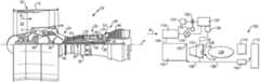
- FIG. 1schematically shows a gas turbine engine.
- FIG. 2Ashows an intercooled cooling system
- FIG. 2Bis a cross section.
- FIG. 2Cshows the FIG. 2A system in a distinct operational condition.
- FIG. 3shows another embodiment.
- FIG. 4shows features of a turbine blade.
- FIG. 1schematically illustrates a gas turbine engine 20 .
- the gas turbine engine 20is disclosed herein as a two-spool turbofan that generally incorporates a fan section 22 , a compressor section 24 , a combustor section 26 and a turbine section 28 .
- the fan section 22drives air along a bypass flow path B in a bypass duct defined within a nacelle 15 , and also drives air along a core flow path C for compression and communication into the combustor section 26 then expansion through the turbine section 28 .
- the exemplary engine 20generally includes a low speed spool 30 and a high speed spool 32 mounted for rotation about an engine central longitudinal axis A relative to an engine static structure 36 via several bearing systems 38 . It should be understood that various bearing systems 38 at various locations may alternatively or additionally be provided, and the location of bearing systems 38 may be varied as appropriate to the application.
- the low speed spool 30generally includes an inner shaft 40 that interconnects a fan 42 , a first (or low) pressure compressor 44 and a first (or low) pressure turbine 46 .
- the inner shaft 40is connected to the fan 42 through a speed change mechanism, which in exemplary gas turbine engine 20 is illustrated as a geared architecture 48 to drive the fan 42 at a lower speed than the low speed spool 30 .
- the high speed spool 32includes an outer shaft 50 that interconnects a second (or high) pressure compressor 52 and a second (or high) pressure turbine 54 .
- a combustor 56is arranged in exemplary gas turbine 20 between the high pressure compressor 52 and the high pressure turbine 54 .
- a mid-turbine frame 57 of the engine static structure 36is arranged generally between the high pressure turbine 54 and the low pressure turbine 46 .
- the mid-turbine frame 57further supports bearing systems 38 in the turbine section 28 .
- the inner shaft 40 and the outer shaft 50are concentric and rotate via bearing systems 38 about the engine central longitudinal axis A which is collinear with their longitudinal axes.
- the core airflowis compressed by the low pressure compressor 44 then the high pressure compressor 52 , mixed and burned with fuel in the combustor 56 , then expanded over the high pressure turbine 54 and low pressure turbine 46 .
- the mid-turbine frame 57includes airfoils 59 which are in the core airflow path C.
- the turbines 46 , 54rotationally drive the respective low speed spool 30 and high speed spool 32 in response to the expansion.
- gear system 48may be located aft of combustor section 26 or even aft of turbine section 28
- fan section 22may be positioned forward or aft of the location of gear system 48 .
- the engine 20 in one exampleis a high-bypass geared aircraft engine.
- the engine 20 bypass ratiois greater than about six (6), with an example embodiment being greater than about ten (10)
- the geared architecture 48is an epicyclic gear train, such as a planetary gear system or other gear system, with a gear reduction ratio of greater than about 2.3
- the low pressure turbine 46has a pressure ratio that is greater than about five.
- the engine 20 bypass ratiois greater than about ten (10:1)
- the fan diameteris significantly larger than that of the low pressure compressor 44
- the low pressure turbine 46has a pressure ratio that is greater than about five 5:1.
- Low pressure turbine 46 pressure ratiois pressure measured prior to inlet of low pressure turbine 46 as related to the pressure at the outlet of the low pressure turbine 46 prior to an exhaust nozzle.
- the geared architecture 48may be an epicycle gear train, such as a planetary gear system or other gear system, with a gear reduction ratio of greater than about 2.3:1. It should be understood, however, that the above parameters are only exemplary of one embodiment of a geared architecture engine and that the present invention is applicable to other gas turbine engines including direct drive turbofans.
- the fan section 22 of the engine 20is designed for a particular flight condition—typically cruise at about 0.8 Mach and about 35,000 feet (10,668 meters).
- TSFCThrust Specific Fuel Consumption
- Low fan pressure ratiois the pressure ratio across the fan blade alone, without a Fan Exit Guide Vane (“FEGV”) system.
- the low fan pressure ratio as disclosed herein according to one non-limiting embodimentis less than about 1.45.
- Low corrected fan tip speedis the actual fan tip speed in ft/sec divided by an industry standard temperature correction of [(Tram °R)/(518.7 °R)] 0.5 .
- the “Low corrected fan tip speed” as disclosed herein according to one non-limiting embodimentis less than about 1150 ft/second (350.5 meters/second).
- FIG. 2Ashows a system 100 for providing cooling air to rotatable components, such as a rotor in the compressor section and/or blades in the turbine section.
- the compressor section 102has a tap 104 connected to tap compressed air for use as cooling air.
- the tap 104is upstream of a downstream most location 105 .
- the tapped airis passed through a heat exchanger 116 , in which the tapped air is cooled, such as by bypass air B.
- the aircould be cooled in locations other than the bypass duct and by fluid other than bypass air B.
- the airthen passes downstream to a valve 118 and to a cooling compressor 120 .
- the cooling compressoris driven through a clutch 122 by an electric motor 124 or 124 could be representative of a shaft connection to one of the engine's spools.
- a control 126is operable to control the valve 118 and clutch 122 .
- Valve 118may be an electrically controllable valve.
- the cooling compressor 120may be utilized to supply compressed cooling air, as will be described below.
- the air flow from cooling compressor 120may be stopped. This can be achieved by opening the clutch 122 and closing the valve 118 .
- a compressor diffuser 106is positioned downstream of the cooling compressor 120 . Air passes into a line 130 and then through a strut 132 in a compressor diffuser 106 , which is downstream of the downstream most location 105 . As known, there are actually a plurality of struts 132 which serve the purpose of connecting inner and outer parts of a diffuser case (not shown) that connects to the endo of the compressor; and surrounds the combustor 108 . As shown, the diffuser 106 is upstream of a combustor section 108 , a first row turbine vane 110 , and a first row turbine blade 112 .
- the air in the struts 132passes into passageways or optional lines flowing toward 136 and/or 138 .
- Line or passage 136extends to cool the disks and hubs of at least the downstream most rotor in a high pressure compressor.
- Line 138may pass through a tangential on-board injector 140 (TOBI) and then to cool the blade 112 and vane 110 .
- TOBItangential on-board injector 140
- a chamber 114is downstream of the point 105 and surrounds the compressor 108 .
- FIG. 2Bshows the interior of the strut 132 .
- an interior chamber 133receives the air passing inwardly from line 130 .
- a check valve 134blocks flow of air from the chamber 114 as long as the pressure of the air at line 130 is higher than the pressure of the air in chamber 114 .
- the cooling compressor 120is designed such that it compresses the air to a pressure significantly higher than the pressure downstream of the downstream point 105 .
- the pressure at point 105is typically known as P 3 .
- the cooling compressor 120is designed to achieve an output of at least about 90% of P 3 but it might also be designed to reach greater than 100% P 3 and in certain applications with different cooling requirements it might go well above P 3 such as 110%-130% of the P 3 pressure, with the output ratio relative to P 3 pressure being defined at 86° F. sea level take-off conditions. In one embodiment it achieves 130% of P 3 .
- valve 134will remain closed and the flow provided to the chamber 133 is not lost to the passage labeled 135 .
- the alternative air controlled by valve 134will be less than P 3 , and still less than the cooling compressor pressure.
- the control 126is can be typically programmed to maintain this airflow during take-off, climb, and other relatively high power conditions.
- the control 126stops flow of the compressed air from the cooling air compressor 120 .
- the valve 134opens due to the higher pressure in chamber 114 .
- the air passing into chamber 133 through passage 135is now air which has not been compressed by the cooling compressor 120 , but rather the air at pressure P 3 .
- Thisprovides efficiencies, in that the cooling compressor 120 is not utilized when not needed and the extraction of power required from the engine for compressor work is reduced.
- FIG. 3shows another embodiment wherein the strut 142 is not the location of where the alternate flow of the air from chamber 114 or the cooling compressor occurs. Rather, there is a chamber 144 located away from the strut 142 which has the check valves 146 closing supply opening 147 which is a connection to air at a lower pressure than that delivered by the cooling compressor during its operation. This embodiment would otherwise operate as the FIG. 2A / 2 B embodiment.
- the chamber 144may be a single chamber having a plurality of check valves 146 , or could be a plurality of discrete chambers.
- FIG. 4is an example of a turbine blade 150 .
- turbine blade 150has skin cooling holes, such as shown at 152 , and internal cooling channels with heat transfer elements, such as trip strips, as shown at 154 .
- the turbine blade 150in modern gas turbine engines, is designed such that it can handle the increasing temperatures and pressures.
- the walls of the turbine blademay be thinner, trip strips, the number of internal passes, the size of the holes, and the spacing between the holes may all be controlled to increase the cooling potential of the cooling air passing through the turbine blade 150 .
- the turbine blade 150can be designed to have less cooling potential under the lower power conditions and at the lower P 3 pressure level seen at the entrance to the cooling passages of the blade when the cooling compressor 120 is not delivering cooling airflow.
- the higher pressure at conditions where the cooling compressor 120 is delivering its higher pressure airis able to drive through an adequately cooled turbine blade even for a turbine blade having lesser cooling potential.
- the skin holesmight be smaller or spread further apart or, internally the passages might be more narrow or the trips strips higher, all to reduce the flow and provide fuel consumption benefits to the engine during low power conditions when higher flow is not needed.
- the flow through the blademight be the same as the one-pressure blade or even higher owing to the elevated pressure chosen by the designer the blade service life goals he has.
- a gas turbine enginehas a plurality of rotatable components housed within a compressor section and a turbine section.
- a tapis connected to a location upstream of a downstream most location in the compressor section.
- the tapis connected to a heat exchanger. Downstream of the heat exchanger is a shut off valve. Downstream of the shut off valve is a cooling compressor.
- the cooling compressoris connected to deliver cooling air through a chamber, and then to at least one of the plurality of rotatable components.
- the chamberis provided with at least one check valve configured to selectively allow flow directly from a more downstream location in the compressor section than the location upstream. The flow from the more downstream location has a higher pressure than a flow from the location upstream. There is a means for stopping operation of the cooling compressor.
- the cooling compressoris configured to compress air to a greater pressure than the higher pressure, such that when the cooling compressor is providing air, the at least one check valve is configured to maintain a closed position, but when the cooling compressor is not providing compressed air, the at least one check valve is configured to allow the higher pressure flow into the chamber.
Landscapes
- Engineering & Computer Science (AREA)
- Chemical & Material Sciences (AREA)
- Combustion & Propulsion (AREA)
- Mechanical Engineering (AREA)
- General Engineering & Computer Science (AREA)
- Physics & Mathematics (AREA)
- Fluid Mechanics (AREA)
- Structures Of Non-Positive Displacement Pumps (AREA)
Abstract
Description
Claims (20)
Priority Applications (2)
| Application Number | Priority Date | Filing Date | Title |
|---|---|---|---|
| US15/956,853US10808619B2 (en) | 2018-04-19 | 2018-04-19 | Intercooled cooling air with advanced cooling system |
| EP19170209.1AEP3557030B1 (en) | 2018-04-19 | 2019-04-18 | Intercooled cooling air by advanced cooling system |
Applications Claiming Priority (1)
| Application Number | Priority Date | Filing Date | Title |
|---|---|---|---|
| US15/956,853US10808619B2 (en) | 2018-04-19 | 2018-04-19 | Intercooled cooling air with advanced cooling system |
Publications (2)
| Publication Number | Publication Date |
|---|---|
| US20190323431A1 US20190323431A1 (en) | 2019-10-24 |
| US10808619B2true US10808619B2 (en) | 2020-10-20 |
Family
ID=66396995
Family Applications (1)
| Application Number | Title | Priority Date | Filing Date |
|---|---|---|---|
| US15/956,853Active2038-07-09US10808619B2 (en) | 2018-04-19 | 2018-04-19 | Intercooled cooling air with advanced cooling system |
Country Status (2)
| Country | Link |
|---|---|
| US (1) | US10808619B2 (en) |
| EP (1) | EP3557030B1 (en) |
Families Citing this family (1)
| Publication number | Priority date | Publication date | Assignee | Title |
|---|---|---|---|---|
| US11021981B2 (en)* | 2018-05-22 | 2021-06-01 | Raytheon Technologies Corporation | Downstream turbine vane cooling for a gas turbine engine |
Citations (165)
| Publication number | Priority date | Publication date | Assignee | Title |
|---|---|---|---|---|
| US2692476A (en) | 1950-11-13 | 1954-10-26 | Boeing Co | Gas turbine engine air starting motor constituting air supply mechanism |
| US3034298A (en)* | 1958-06-12 | 1962-05-15 | Gen Motors Corp | Turbine cooling system |
| GB1244340A (en) | 1968-12-23 | 1971-08-25 | Rolls Royce | Front fan gas turbine engine |
| US3610698A (en)* | 1968-05-15 | 1971-10-05 | Jean Gachot | Compressed air brake systems for vehicles |
| US3878677A (en) | 1974-04-10 | 1975-04-22 | United Aircraft Corp | Auxiliary turbine/compressor system for turbine engine |
| DE2852057A1 (en) | 1977-12-02 | 1979-06-07 | Hitachi Ltd | METHOD AND DEVICE FOR COOLING A GAS TURBINE BLADE |
| US4254618A (en)* | 1977-08-18 | 1981-03-10 | General Electric Company | Cooling air cooler for a gas turbofan engine |
| US4304093A (en) | 1979-08-31 | 1981-12-08 | General Electric Company | Variable clearance control for a gas turbine engine |
| GB2152148A (en) | 1983-12-23 | 1985-07-31 | United Technologies Corp | Controlling bearing chamber temperature in gas turbine engine |
| US4539945A (en) | 1983-05-31 | 1985-09-10 | Roberto Bosisio S.P.A. | Internal combustion power pack with injection pump ventilation system |
| US4882902A (en) | 1986-04-30 | 1989-11-28 | General Electric Company | Turbine cooling air transferring apparatus |
| US4967552A (en) | 1986-02-07 | 1990-11-06 | Hitachi, Ltd. | Method and apparatus for controlling temperatures of turbine casing and turbine rotor |
| EP0447886A1 (en) | 1990-03-23 | 1991-09-25 | Asea Brown Boveri Ag | Axial flow gas turbine |
| US5056335A (en) | 1990-04-02 | 1991-10-15 | General Electric Company | Auxiliary refrigerated air system employing input air from turbine engine compressor after bypassing and conditioning within auxiliary system |
| EP0469825A2 (en) | 1990-07-30 | 1992-02-05 | General Electric Company | Precooling heat exchange arrangement integral with mounting structure fairing of gas turbine engine |
| US5269135A (en) | 1991-10-28 | 1993-12-14 | General Electric Company | Gas turbine engine fan cooled heat exchanger |
| US5305616A (en) | 1992-03-23 | 1994-04-26 | General Electric Company | Gas turbine engine cooling system |
| EP0608142A1 (en) | 1993-01-21 | 1994-07-27 | General Electric Company | Gas turbine engine cooling system |
| US5414992A (en) | 1993-08-06 | 1995-05-16 | United Technologies Corporation | Aircraft cooling method |
| US5452573A (en)* | 1994-01-31 | 1995-09-26 | United Technologies Corporation | High pressure air source for aircraft and engine requirements |
| US5498126A (en) | 1994-04-28 | 1996-03-12 | United Technologies Corporation | Airfoil with dual source cooling |
| US5724806A (en) | 1995-09-11 | 1998-03-10 | General Electric Company | Extracted, cooled, compressed/intercooled, cooling/combustion air for a gas turbine engine |
| US5758485A (en) | 1995-08-28 | 1998-06-02 | Asea Brown Boveri Ag | Method of operating gas turbine power plant with intercooler |
| JPH1136889A (en) | 1997-07-15 | 1999-02-09 | Mitsubishi Heavy Ind Ltd | Gas turbine cooler |
| US5867979A (en) | 1996-03-28 | 1999-02-09 | Rolls-Royce Plc | Gas turbine engine system |
| EP0903484A2 (en) | 1997-09-18 | 1999-03-24 | Kabushiki Kaisha Toshiba | Gas turbine plant with fuel preheater |
| US5918458A (en) | 1997-02-14 | 1999-07-06 | General Electric Company | System and method of providing clean filtered cooling air to a hot portion of a gas turbine engine |
| US6050079A (en) | 1997-12-24 | 2000-04-18 | General Electric Company | Modulated turbine cooling system |
| US6065282A (en) | 1997-10-29 | 2000-05-23 | Mitsubishi Heavy Industries, Ltd. | System for cooling blades in a gas turbine |
| US6134880A (en) | 1997-12-31 | 2000-10-24 | Concepts Eti, Inc. | Turbine engine with intercooler in bypass air passage |
| US6430931B1 (en) | 1997-10-22 | 2002-08-13 | General Electric Company | Gas turbine in-line intercooler |
| US6487863B1 (en) | 2001-03-30 | 2002-12-03 | Siemens Westinghouse Power Corporation | Method and apparatus for cooling high temperature components in a gas turbine |
| US20030046938A1 (en) | 2001-09-12 | 2003-03-13 | Mortzheim Jason Paul | Apparatus and methods for controlling flow in turbomachinery |
| WO2003037715A1 (en) | 2001-10-29 | 2003-05-08 | Pratt & Whitney Canada Corp. | Passive cooling system for auxiliary power unit installation |
| EP1314872A1 (en) | 1999-11-10 | 2003-05-28 | Hitachi, Ltd. | Gas turbine equipment and gas turbine cooling method |
| US6612114B1 (en) | 2000-02-29 | 2003-09-02 | Daimlerchrysler Ag | Cooling air system for gas turbine |
| US20040088995A1 (en) | 2001-05-10 | 2004-05-13 | Sergej Reissig | Method for cooling a gas turbine and gas turbine installation |
| FR2851295A1 (en) | 2003-02-19 | 2004-08-20 | Snecma Moteurs | Air collection system for aviation turbo-reactor, has flow adjustment valves on collection ducts extending between clip points that are at respective outlet and inlet of high-pressure compressor |
| US6892523B2 (en) | 2000-01-13 | 2005-05-17 | Alstom Technology Ltd | Cooling-air cooler for a gas-turbine plant and use of such a cooling-air cooler |
| US20050172612A1 (en) | 2001-08-29 | 2005-08-11 | Hitachi, Ltd. | Gas turbine and gas turbine high temperature section cooling method |
| US20070022735A1 (en) | 2005-07-29 | 2007-02-01 | General Electric Company | Pto assembly for a gas turbine engine |
| US7237386B2 (en) | 2001-11-02 | 2007-07-03 | Alstom Technology Ltd | Process for controlling the cooling air mass flow of a gas turbine set |
| US7246484B2 (en) | 2003-08-25 | 2007-07-24 | General Electric Company | FLADE gas turbine engine with counter-rotatable fans |
| US20070213917A1 (en) | 2006-03-09 | 2007-09-13 | Pratt & Whitney Canada Corp. | Gas turbine speed detection |
| US7284377B2 (en) | 2004-05-28 | 2007-10-23 | General Electric Company | Method and apparatus for operating an intercooler for a gas turbine engine |
| US20070245738A1 (en) | 2006-04-20 | 2007-10-25 | Stretton Richard G | Heat exchanger arrangement |
| US7306424B2 (en) | 2004-12-29 | 2007-12-11 | United Technologies Corporation | Blade outer seal with micro axial flow cooling system |
| US20080028763A1 (en) | 2006-08-03 | 2008-02-07 | United Technologies Corporation | Thermal management system with thrust recovery for a gas turbine engine fan nacelle assembly |
| US7334412B2 (en) | 2002-11-11 | 2008-02-26 | Siemens Aktiengesellschaft | Cooling air and injected liquid system for gas turbine blades |
| US7347637B2 (en) | 2003-09-04 | 2008-03-25 | Sharp Kabushiki Kaisha | Hybrid paper supply module and image forming apparatus equipped with such hybrid paper supply module |
| WO2008082335A1 (en) | 2006-12-29 | 2008-07-10 | Volvo Aero Corporation | A power transmission device for a gas turbine engine |
| EP1944475A2 (en) | 2007-01-08 | 2008-07-16 | Pratt & Whitney Rocketdyne Inc. | Heat exchange system |
| US20080230651A1 (en) | 2005-09-26 | 2008-09-25 | Airbus France | Turbofan Provided With a Pre-Cooler |
| US20080253881A1 (en) | 2006-09-09 | 2008-10-16 | Rolls-Royce Plc | Engine |
| US20090007567A1 (en) | 2006-01-19 | 2009-01-08 | Airbus France | Dual Flow Turbine Engine Equipped with a Precooler |
| US7500365B2 (en) | 2005-05-05 | 2009-03-10 | United Technologies Corporation | Accessory gearbox |
| US20090090096A1 (en) | 2007-10-03 | 2009-04-09 | United Technologies Corporation | Epicyclic gear train for variable cycle engine |
| US20090145102A1 (en) | 2007-12-05 | 2009-06-11 | United Technologies Corp. | Gas Turbine Engine Systems Involving Tip Fans |
| US7552591B2 (en) | 2005-02-11 | 2009-06-30 | Snecma | Twin spool turbine engine with power take-off means on the low-pressure and high-pressure rotors, and power take-off module for the turbine engine |
| EP2085599A2 (en) | 2008-01-25 | 2009-08-05 | United Technologies Corporation | Shared flow thermal management system |
| US20090196736A1 (en) | 2008-02-01 | 2009-08-06 | Ajit Singh Sengar | Apparatus and related methods for turbine cooling |
| US20090226297A1 (en) | 2008-03-07 | 2009-09-10 | Japan Aerospace Exploration Agency | High bypass-ratio turbofan jet engine |
| US20090272120A1 (en) | 2003-08-18 | 2009-11-05 | Peter Tiemann | Diffuser for a gas turbine, and gas turbine for power generation |
| EP2128023A1 (en) | 2008-05-29 | 2009-12-02 | Pratt & Whitney Canada Corp. | Bleed air cooler assembly for a gas turbine engine, corresponding kit and installation method |
| US20100043396A1 (en) | 2008-08-25 | 2010-02-25 | General Electric Company | Gas turbine engine fan bleed heat exchanger system |
| US7698884B2 (en) | 2003-09-19 | 2010-04-20 | Rolls-Royce Plc | Power transmission arrangement |
| US20100154434A1 (en) | 2008-08-06 | 2010-06-24 | Mitsubishi Heavy Industries, Ltd. | Gas Turbine |
| US7765788B2 (en) | 2006-07-06 | 2010-08-03 | United Technologies Corporation | Cooling exchanger duct |
| US7823389B2 (en) | 2006-11-15 | 2010-11-02 | General Electric Company | Compound clearance control engine |
| US7882691B2 (en) | 2007-07-05 | 2011-02-08 | Hamilton Sundstrand Corporation | High to low pressure spool summing gearbox for accessory power extraction and electric start |
| US7886520B2 (en) | 2006-04-20 | 2011-02-15 | Rolls-Royce Plc | Gas turbine engine |
| US20110036066A1 (en) | 2009-08-13 | 2011-02-17 | General Electric Company | System and method for injection of cooling air into exhaust gas flow |
| US7926289B2 (en) | 2006-11-10 | 2011-04-19 | General Electric Company | Dual interstage cooled engine |
| US20110088405A1 (en) | 2009-10-15 | 2011-04-21 | John Biagio Turco | Gas turbine engine temperature modulated cooling flow |
| US20110120083A1 (en) | 2009-11-20 | 2011-05-26 | Rollin George Giffin | Gas turbine engine with outer fans |
| EP2362081A1 (en) | 2010-02-19 | 2011-08-31 | United Technologies Corporation | Bearing compartment pressurization and shaft ventilation system |
| US8015828B2 (en) | 2007-04-03 | 2011-09-13 | General Electric Company | Power take-off system and gas turbine engine assembly including same |
| US20110247344A1 (en) | 2010-04-09 | 2011-10-13 | Glahn Jorn A | Rear hub cooling for high pressure compressor |
| US8037686B2 (en) | 2002-11-01 | 2011-10-18 | George Lasker | Uncoupled, thermal-compressor, gas-turbine engine |
| US8087249B2 (en) | 2008-12-23 | 2012-01-03 | General Electric Company | Turbine cooling air from a centrifugal compressor |
| US20120067055A1 (en) | 2009-04-17 | 2012-03-22 | Echogen Power Systems, Llc | System and method for managing thermal issues in gas turbine engines |
| US20120102915A1 (en) | 2009-03-17 | 2012-05-03 | Constantine Baltas | Gas turbine engine bifurcation located fan variable area nozzle |
| US8181443B2 (en) | 2008-12-10 | 2012-05-22 | Pratt & Whitney Canada Corp. | Heat exchanger to cool turbine air cooling flow |
| US20120159961A1 (en) | 2010-12-24 | 2012-06-28 | Michael Stephen Krautheim | Gas turbine engine heat exchanger |
| US20120180509A1 (en) | 2011-01-14 | 2012-07-19 | Hamilton Sundstrand Corporation | Low pressure bleed architecture |
| EP2540991A2 (en) | 2011-06-28 | 2013-01-02 | United Technologies Corporation | Mechanism for turbine engine start from low spool |
| US8350398B2 (en) | 2008-11-28 | 2013-01-08 | Rolls-Royce, Plc | Aeroengine starter/generator arrangement |
| US20130036747A1 (en) | 2011-06-16 | 2013-02-14 | Alstom Technology Ltd | Method for cooling a gas turbine plant and gas turbine plant for implementing the method |
| US8397487B2 (en) | 2011-02-28 | 2013-03-19 | General Electric Company | Environmental control system supply precooler bypass |
| US20130067928A1 (en) | 2011-08-22 | 2013-03-21 | Alstom Technology Ltd | Method for operating a gas turbine plant and gas turbine plant for implementing the method |
| US8402742B2 (en) | 2007-12-05 | 2013-03-26 | United Technologies Corporation | Gas turbine engine systems involving tip fans |
| EP2584172A2 (en) | 2011-10-21 | 2013-04-24 | United Technologies Corporation | Constant speed transmission for gas turbine engine |
| US20130098059A1 (en) | 2011-10-21 | 2013-04-25 | Gabriel L. Suciu | Windmill operation of a gas turbine engine |
| US8434997B2 (en) | 2007-08-22 | 2013-05-07 | United Technologies Corporation | Gas turbine engine case for clearance control |
| US20130145744A1 (en) | 2011-12-12 | 2013-06-13 | Honeywell International Inc. | System for directing air flow to a plurality of plena |
| US20130145774A1 (en) | 2011-12-07 | 2013-06-13 | Hung Duong | Accessory gearbox with tower shaft removal capability |
| EP2604825A2 (en) | 2011-12-14 | 2013-06-19 | Rolls-Royce plc | Controller for cooling the turbine section of a gas turbine engine |
| US20130186102A1 (en) | 2012-01-25 | 2013-07-25 | Honeywell International Inc. | Gas turbine engine in-board cooled cooling air system |
| US20130199156A1 (en) | 2010-03-26 | 2013-08-08 | Robert A. Ress, Jr. | Adaptive fan system for a variable cycle turbofan engine |
| US8511967B2 (en) | 2008-05-21 | 2013-08-20 | United Technologies Corporation | Gearbox assembly |
| US8522529B2 (en) | 2005-07-28 | 2013-09-03 | Airbus Operations Sas | Propulsion unit for aircraft with heat exchanger having front inlet faces for cooling air flow and hot air flow |
| US20130239583A1 (en) | 2012-03-14 | 2013-09-19 | United Technologies Corporation | Pump system for hpc eps parasitic loss elimination |
| WO2013154631A1 (en) | 2012-01-31 | 2013-10-17 | United Technologies Corporation | Gas turbine engine buffer system providing zoned ventilation |
| US20130319002A1 (en) | 2012-06-05 | 2013-12-05 | Dmitriy B. Sidelkovskiy | Nacelle bifurcation for gas turbine engine |
| US8602717B2 (en) | 2010-10-28 | 2013-12-10 | United Technologies Corporation | Compression system for turbomachine heat exchanger |
| US8621871B2 (en) | 2007-10-09 | 2014-01-07 | United Technologies Corporation | Systems and methods involving multiple torque paths for gas turbine engines |
| US20140020506A1 (en) | 2012-07-20 | 2014-01-23 | Hung Duong | Gearbox for gas turbine engine |
| WO2014046713A1 (en) | 2012-09-20 | 2014-03-27 | United Technologies Corporation | Geared gas turbine engine accessory gearbox |
| US8712739B2 (en) | 2010-11-19 | 2014-04-29 | General Electric Company | System and method for hybrid risk modeling of turbomachinery |
| US8727703B2 (en) | 2010-09-07 | 2014-05-20 | Siemens Energy, Inc. | Gas turbine engine |
| EP2733322A1 (en) | 2012-11-15 | 2014-05-21 | Magneti Marelli S.p.A. | Exhaust gas heat exchanger with thermal energy recovery for an exhaust system of an internal combustion engine |
| US20140137417A1 (en) | 2012-11-19 | 2014-05-22 | Helen Of Troy Limited | Device for cutting small food items |
| WO2014092777A1 (en) | 2012-12-10 | 2014-06-19 | United Technologies Corporation | Gas turbine engine with plural accessory air paths |
| US8776952B2 (en) | 2006-05-11 | 2014-07-15 | United Technologies Corporation | Thermal management system for turbofan engines |
| US20140196469A1 (en) | 2011-08-11 | 2014-07-17 | Hamilton Sundstrand Corporation | Low pressure compressor bleed exit for an aircraft pressurization system |
| US20140208768A1 (en) | 2012-01-06 | 2014-07-31 | Rolls-Royce Plc | Coolant supply system |
| WO2014120125A1 (en) | 2013-01-29 | 2014-08-07 | United Technologies Corporation | Gas turbine engine with lower bifurcation heat exchanger |
| US20140230444A1 (en) | 2013-02-15 | 2014-08-21 | General Electric Company | System and Method for Reducing Back Pressure in a Gas Turbine System |
| US8814502B2 (en) | 2011-05-31 | 2014-08-26 | Pratt & Whitney Canada Corp. | Dual input drive AGB for gas turbine engines |
| US20140250898A1 (en) | 2012-01-24 | 2014-09-11 | The Boeing Company | Bleed air systems for use with aircrafts and related methods |
| US20140260326A1 (en) | 2012-10-02 | 2014-09-18 | United Technologies Corporation | Geared turbofan engine with high compressor exit temperature |
| US20140311157A1 (en) | 2012-12-19 | 2014-10-23 | Vincent P. Laurello | Vane carrier temperature control system in a gas turbine engine |
| US8876465B2 (en) | 2010-04-28 | 2014-11-04 | Rolls-Royce Plc | Gas turbine engine |
| US20140341704A1 (en) | 2013-05-16 | 2014-11-20 | Rolls-Royce Plc | Heat exchange arrangement |
| US20140352315A1 (en) | 2013-05-31 | 2014-12-04 | General Electric Company | Cooled cooling air system for a gas turbine |
| US8961108B2 (en) | 2012-04-04 | 2015-02-24 | United Technologies Corporation | Cooling system for a turbine vane |
| EP2865981A1 (en) | 2013-10-28 | 2015-04-29 | Honeywell International Inc. | Counter-flow heat exchange systems |
| US20150285147A1 (en) | 2014-04-03 | 2015-10-08 | United Technologies Corporation | Cooling System with a Bearing Compartment Bypass |
| EP2942490A1 (en) | 2014-05-09 | 2015-11-11 | United Technologies Corporation | Turbine clearance control system and method for improved variable cycle gas turbine engine fuel burn |
| US20150330236A1 (en) | 2014-05-13 | 2015-11-19 | Rolls-Royce Plc | Bifurcation fairing |
| US20150354465A1 (en) | 2014-06-06 | 2015-12-10 | United Technologies Corporation | Turbine stage cooling |
| US20150354822A1 (en) | 2014-06-06 | 2015-12-10 | United Technologies Corporation | Turbine stage cooling |
| EP2960468A1 (en) | 2014-06-27 | 2015-12-30 | Frederick M. Schwarz | Geared turbofan engine with low pressure environmental control system for aircraft |
| US20160010554A1 (en)* | 2013-02-28 | 2016-01-14 | United Technologies Corporation | Method and apparatus for handling pre-diffuser airflow for use in adjusting a temperature profile |
| US9255492B2 (en) | 2011-12-14 | 2016-02-09 | Rolls-Royce Plc | Gas turbine engine having a multi-variable closed loop controller for regulating tip clearance |
| US9297391B2 (en) | 2009-05-14 | 2016-03-29 | Mtu Aero Engines Gmbh | Flow device comprising a cavity cooling system |
| US20160131036A1 (en) | 2014-11-06 | 2016-05-12 | United Technologies Corporation | Thermal management system for a gas turbine engine |
| US20160131037A1 (en) | 2013-07-17 | 2016-05-12 | United Technologies Corporation | Supply duct for cooling air |
| US20160169118A1 (en) | 2014-12-12 | 2016-06-16 | United Technologies Corporation | Dual tower shaft gearbox for gas turbine engine |
| US20160215732A1 (en) | 2013-09-24 | 2016-07-28 | United Technologies Corporation | Bypass duct heat exchanger placement |
| US20160236790A1 (en) | 2014-08-29 | 2016-08-18 | Tzunum, Inc. | System and methods for implementing regional air transit network using hybrid-electric aircraft |
| US20160237906A1 (en) | 2015-02-12 | 2016-08-18 | United Technologies Corporation | Intercooled cooling air with heat exchanger packaging |
| US9429072B2 (en) | 2013-05-22 | 2016-08-30 | General Electric Company | Return fluid air cooler system for turbine cooling with optional power extraction |
| GB2536628A (en) | 2015-03-19 | 2016-09-28 | Rolls Royce Plc | HPT Integrated interstage seal and cooling air passageways |
| EP3085924A1 (en) | 2015-04-24 | 2016-10-26 | United Technologies Corporation | Cooling air intercooling with cooling air tapped from plural locations |
| EP3085923A1 (en) | 2015-04-24 | 2016-10-26 | United Technologies Corporation | Cooling air intercooling with dual pass heat exchanger |
| US20160312711A1 (en) | 2015-04-24 | 2016-10-27 | United Technologies Corporation | Intercooled cooling air with plural heat exchangers |
| US20160341125A1 (en) | 2015-02-05 | 2016-11-24 | Powerphase Llc | Turbocooled vane of a gas turbine engine |
| US20160369697A1 (en) | 2015-06-16 | 2016-12-22 | United Technologies Corporation | Cooled cooling air system for a turbofan engine |
| US20170009657A1 (en) | 2015-07-07 | 2017-01-12 | United Technologies Corporation | Cooled cooling air system for a turbofan engine |
| EP3121411A1 (en) | 2015-07-21 | 2017-01-25 | United Technologies Corporation | Intercooled cooling air using existing heat exchanger |
| US20170044980A1 (en) | 2015-08-14 | 2017-02-16 | United Technologies Corporation | Heat exchanger for cooled cooling air with adjustable damper |
| US20170044982A1 (en) | 2015-08-14 | 2017-02-16 | United Technologies Corporation | Heat exchanger for cooled cooling air |
| US20170152765A1 (en) | 2014-03-24 | 2017-06-01 | Mitsubishi Hitachi Power Systems, Ltd. | Waste heat recovery system, gas turbine plant provided with same, waste heat recovery method, and installation method for waste heat recovery system |
| US20170159568A1 (en) | 2015-12-03 | 2017-06-08 | General Electric Company | Intercooling system and method for a gas turbine engine |
| US20170167388A1 (en) | 2015-12-14 | 2017-06-15 | United Technologies Corporation | Intercooled cooling air with auxiliary compressor control |
| US20170175632A1 (en) | 2015-12-18 | 2017-06-22 | United Technologies Corporation | Cooling air heat exchanger scoop |
| US20170184027A1 (en) | 2015-12-29 | 2017-06-29 | General Electric Company | Method and system for compressor and turbine cooling |
| CN106917641A (en) | 2017-04-25 | 2017-07-04 | 田忠武 | A kind of new aero-engine pressure turbine |
| US20170204787A1 (en) | 2016-01-19 | 2017-07-20 | United Technologies Corporation | Heat exchanger array |
| US20170234224A1 (en) | 2016-02-16 | 2017-08-17 | General Electric Company | Method and system for modulated turbine cooling as a function of engine health |
| RU2016115404A (en) | 2016-04-20 | 2017-10-23 | Акционерное общество "Климов" | GAS-TURBINE ENGINE GAS GENERATOR |
| US9816897B2 (en) | 2012-06-06 | 2017-11-14 | Harris Corporation | Wireless engine monitoring system and associated engine wireless sensor network |
| US9818242B2 (en) | 2014-12-16 | 2017-11-14 | University Of Southern California | Gas turbine engine anomaly detections and fault identifications |
| EP3296543A1 (en) | 2016-09-19 | 2018-03-21 | United Technologies Corporation | Gas turbine engine with intercooled cooling air and turbine drive |
Family Cites Families (1)
| Publication number | Priority date | Publication date | Assignee | Title |
|---|---|---|---|---|
| US10550768B2 (en)* | 2016-11-08 | 2020-02-04 | United Technologies Corporation | Intercooled cooled cooling integrated air cycle machine |
- 2018
- 2018-04-19USUS15/956,853patent/US10808619B2/enactiveActive
- 2019
- 2019-04-18EPEP19170209.1Apatent/EP3557030B1/enactiveActive
Patent Citations (174)
| Publication number | Priority date | Publication date | Assignee | Title |
|---|---|---|---|---|
| US2692476A (en) | 1950-11-13 | 1954-10-26 | Boeing Co | Gas turbine engine air starting motor constituting air supply mechanism |
| US3034298A (en)* | 1958-06-12 | 1962-05-15 | Gen Motors Corp | Turbine cooling system |
| US3610698A (en)* | 1968-05-15 | 1971-10-05 | Jean Gachot | Compressed air brake systems for vehicles |
| GB1244340A (en) | 1968-12-23 | 1971-08-25 | Rolls Royce | Front fan gas turbine engine |
| US3878677A (en) | 1974-04-10 | 1975-04-22 | United Aircraft Corp | Auxiliary turbine/compressor system for turbine engine |
| US4254618A (en)* | 1977-08-18 | 1981-03-10 | General Electric Company | Cooling air cooler for a gas turbofan engine |
| DE2852057A1 (en) | 1977-12-02 | 1979-06-07 | Hitachi Ltd | METHOD AND DEVICE FOR COOLING A GAS TURBINE BLADE |
| US4304093A (en) | 1979-08-31 | 1981-12-08 | General Electric Company | Variable clearance control for a gas turbine engine |
| US4539945A (en) | 1983-05-31 | 1985-09-10 | Roberto Bosisio S.P.A. | Internal combustion power pack with injection pump ventilation system |
| GB2152148A (en) | 1983-12-23 | 1985-07-31 | United Technologies Corp | Controlling bearing chamber temperature in gas turbine engine |
| US4967552A (en) | 1986-02-07 | 1990-11-06 | Hitachi, Ltd. | Method and apparatus for controlling temperatures of turbine casing and turbine rotor |
| US4882902A (en) | 1986-04-30 | 1989-11-28 | General Electric Company | Turbine cooling air transferring apparatus |
| EP0447886A1 (en) | 1990-03-23 | 1991-09-25 | Asea Brown Boveri Ag | Axial flow gas turbine |
| US5056335A (en) | 1990-04-02 | 1991-10-15 | General Electric Company | Auxiliary refrigerated air system employing input air from turbine engine compressor after bypassing and conditioning within auxiliary system |
| EP0469825A2 (en) | 1990-07-30 | 1992-02-05 | General Electric Company | Precooling heat exchange arrangement integral with mounting structure fairing of gas turbine engine |
| US5269135A (en) | 1991-10-28 | 1993-12-14 | General Electric Company | Gas turbine engine fan cooled heat exchanger |
| US5305616A (en) | 1992-03-23 | 1994-04-26 | General Electric Company | Gas turbine engine cooling system |
| US5392614A (en) | 1992-03-23 | 1995-02-28 | General Electric Company | Gas turbine engine cooling system |
| EP0608142A1 (en) | 1993-01-21 | 1994-07-27 | General Electric Company | Gas turbine engine cooling system |
| US5414992A (en) | 1993-08-06 | 1995-05-16 | United Technologies Corporation | Aircraft cooling method |
| US5452573A (en)* | 1994-01-31 | 1995-09-26 | United Technologies Corporation | High pressure air source for aircraft and engine requirements |
| US5498126A (en) | 1994-04-28 | 1996-03-12 | United Technologies Corporation | Airfoil with dual source cooling |
| US5758485A (en) | 1995-08-28 | 1998-06-02 | Asea Brown Boveri Ag | Method of operating gas turbine power plant with intercooler |
| US5724806A (en) | 1995-09-11 | 1998-03-10 | General Electric Company | Extracted, cooled, compressed/intercooled, cooling/combustion air for a gas turbine engine |
| US5867979A (en) | 1996-03-28 | 1999-02-09 | Rolls-Royce Plc | Gas turbine engine system |
| US5918458A (en) | 1997-02-14 | 1999-07-06 | General Electric Company | System and method of providing clean filtered cooling air to a hot portion of a gas turbine engine |
| JPH1136889A (en) | 1997-07-15 | 1999-02-09 | Mitsubishi Heavy Ind Ltd | Gas turbine cooler |
| EP0903484A2 (en) | 1997-09-18 | 1999-03-24 | Kabushiki Kaisha Toshiba | Gas turbine plant with fuel preheater |
| US6430931B1 (en) | 1997-10-22 | 2002-08-13 | General Electric Company | Gas turbine in-line intercooler |
| US6065282A (en) | 1997-10-29 | 2000-05-23 | Mitsubishi Heavy Industries, Ltd. | System for cooling blades in a gas turbine |
| US6050079A (en) | 1997-12-24 | 2000-04-18 | General Electric Company | Modulated turbine cooling system |
| US6134880A (en) | 1997-12-31 | 2000-10-24 | Concepts Eti, Inc. | Turbine engine with intercooler in bypass air passage |
| EP1314872A1 (en) | 1999-11-10 | 2003-05-28 | Hitachi, Ltd. | Gas turbine equipment and gas turbine cooling method |
| US6892523B2 (en) | 2000-01-13 | 2005-05-17 | Alstom Technology Ltd | Cooling-air cooler for a gas-turbine plant and use of such a cooling-air cooler |
| US6612114B1 (en) | 2000-02-29 | 2003-09-02 | Daimlerchrysler Ag | Cooling air system for gas turbine |
| US6487863B1 (en) | 2001-03-30 | 2002-12-03 | Siemens Westinghouse Power Corporation | Method and apparatus for cooling high temperature components in a gas turbine |
| US20040088995A1 (en) | 2001-05-10 | 2004-05-13 | Sergej Reissig | Method for cooling a gas turbine and gas turbine installation |
| US20050172612A1 (en) | 2001-08-29 | 2005-08-11 | Hitachi, Ltd. | Gas turbine and gas turbine high temperature section cooling method |
| US20030046938A1 (en) | 2001-09-12 | 2003-03-13 | Mortzheim Jason Paul | Apparatus and methods for controlling flow in turbomachinery |
| WO2003037715A1 (en) | 2001-10-29 | 2003-05-08 | Pratt & Whitney Canada Corp. | Passive cooling system for auxiliary power unit installation |
| US7237386B2 (en) | 2001-11-02 | 2007-07-03 | Alstom Technology Ltd | Process for controlling the cooling air mass flow of a gas turbine set |
| US8037686B2 (en) | 2002-11-01 | 2011-10-18 | George Lasker | Uncoupled, thermal-compressor, gas-turbine engine |
| US7334412B2 (en) | 2002-11-11 | 2008-02-26 | Siemens Aktiengesellschaft | Cooling air and injected liquid system for gas turbine blades |
| FR2851295A1 (en) | 2003-02-19 | 2004-08-20 | Snecma Moteurs | Air collection system for aviation turbo-reactor, has flow adjustment valves on collection ducts extending between clip points that are at respective outlet and inlet of high-pressure compressor |
| US8572982B2 (en) | 2003-08-18 | 2013-11-05 | Siemens Aktiengesellschaft | Diffuser having distribution element for providing part-flow |
| US20090272120A1 (en) | 2003-08-18 | 2009-11-05 | Peter Tiemann | Diffuser for a gas turbine, and gas turbine for power generation |
| US7246484B2 (en) | 2003-08-25 | 2007-07-24 | General Electric Company | FLADE gas turbine engine with counter-rotatable fans |
| US7347637B2 (en) | 2003-09-04 | 2008-03-25 | Sharp Kabushiki Kaisha | Hybrid paper supply module and image forming apparatus equipped with such hybrid paper supply module |
| US7698884B2 (en) | 2003-09-19 | 2010-04-20 | Rolls-Royce Plc | Power transmission arrangement |
| US7284377B2 (en) | 2004-05-28 | 2007-10-23 | General Electric Company | Method and apparatus for operating an intercooler for a gas turbine engine |
| US7306424B2 (en) | 2004-12-29 | 2007-12-11 | United Technologies Corporation | Blade outer seal with micro axial flow cooling system |
| US7552591B2 (en) | 2005-02-11 | 2009-06-30 | Snecma | Twin spool turbine engine with power take-off means on the low-pressure and high-pressure rotors, and power take-off module for the turbine engine |
| US7500365B2 (en) | 2005-05-05 | 2009-03-10 | United Technologies Corporation | Accessory gearbox |
| US8522529B2 (en) | 2005-07-28 | 2013-09-03 | Airbus Operations Sas | Propulsion unit for aircraft with heat exchanger having front inlet faces for cooling air flow and hot air flow |
| US20070022735A1 (en) | 2005-07-29 | 2007-02-01 | General Electric Company | Pto assembly for a gas turbine engine |
| US20080230651A1 (en) | 2005-09-26 | 2008-09-25 | Airbus France | Turbofan Provided With a Pre-Cooler |
| US20090007567A1 (en) | 2006-01-19 | 2009-01-08 | Airbus France | Dual Flow Turbine Engine Equipped with a Precooler |
| US20070213917A1 (en) | 2006-03-09 | 2007-09-13 | Pratt & Whitney Canada Corp. | Gas turbine speed detection |
| US7886520B2 (en) | 2006-04-20 | 2011-02-15 | Rolls-Royce Plc | Gas turbine engine |
| US20070245738A1 (en) | 2006-04-20 | 2007-10-25 | Stretton Richard G | Heat exchanger arrangement |
| US8776952B2 (en) | 2006-05-11 | 2014-07-15 | United Technologies Corporation | Thermal management system for turbofan engines |
| US7765788B2 (en) | 2006-07-06 | 2010-08-03 | United Technologies Corporation | Cooling exchanger duct |
| US20080028763A1 (en) | 2006-08-03 | 2008-02-07 | United Technologies Corporation | Thermal management system with thrust recovery for a gas turbine engine fan nacelle assembly |
| US20080253881A1 (en) | 2006-09-09 | 2008-10-16 | Rolls-Royce Plc | Engine |
| US7926289B2 (en) | 2006-11-10 | 2011-04-19 | General Electric Company | Dual interstage cooled engine |
| US7823389B2 (en) | 2006-11-15 | 2010-11-02 | General Electric Company | Compound clearance control engine |
| WO2008082335A1 (en) | 2006-12-29 | 2008-07-10 | Volvo Aero Corporation | A power transmission device for a gas turbine engine |
| EP1944475A2 (en) | 2007-01-08 | 2008-07-16 | Pratt & Whitney Rocketdyne Inc. | Heat exchange system |
| US8015828B2 (en) | 2007-04-03 | 2011-09-13 | General Electric Company | Power take-off system and gas turbine engine assembly including same |
| US7882691B2 (en) | 2007-07-05 | 2011-02-08 | Hamilton Sundstrand Corporation | High to low pressure spool summing gearbox for accessory power extraction and electric start |
| US8434997B2 (en) | 2007-08-22 | 2013-05-07 | United Technologies Corporation | Gas turbine engine case for clearance control |
| US20090090096A1 (en) | 2007-10-03 | 2009-04-09 | United Technologies Corporation | Epicyclic gear train for variable cycle engine |
| US8621871B2 (en) | 2007-10-09 | 2014-01-07 | United Technologies Corporation | Systems and methods involving multiple torque paths for gas turbine engines |
| US20090145102A1 (en) | 2007-12-05 | 2009-06-11 | United Technologies Corp. | Gas Turbine Engine Systems Involving Tip Fans |
| US8402742B2 (en) | 2007-12-05 | 2013-03-26 | United Technologies Corporation | Gas turbine engine systems involving tip fans |
| EP2085599A2 (en) | 2008-01-25 | 2009-08-05 | United Technologies Corporation | Shared flow thermal management system |
| US9234481B2 (en) | 2008-01-25 | 2016-01-12 | United Technologies Corporation | Shared flow thermal management system |
| US20090196736A1 (en) | 2008-02-01 | 2009-08-06 | Ajit Singh Sengar | Apparatus and related methods for turbine cooling |
| US20090226297A1 (en) | 2008-03-07 | 2009-09-10 | Japan Aerospace Exploration Agency | High bypass-ratio turbofan jet engine |
| US8511967B2 (en) | 2008-05-21 | 2013-08-20 | United Technologies Corporation | Gearbox assembly |
| EP2128023A1 (en) | 2008-05-29 | 2009-12-02 | Pratt & Whitney Canada Corp. | Bleed air cooler assembly for a gas turbine engine, corresponding kit and installation method |
| US20100154434A1 (en) | 2008-08-06 | 2010-06-24 | Mitsubishi Heavy Industries, Ltd. | Gas Turbine |
| US20100043396A1 (en) | 2008-08-25 | 2010-02-25 | General Electric Company | Gas turbine engine fan bleed heat exchanger system |
| US8350398B2 (en) | 2008-11-28 | 2013-01-08 | Rolls-Royce, Plc | Aeroengine starter/generator arrangement |
| US8181443B2 (en) | 2008-12-10 | 2012-05-22 | Pratt & Whitney Canada Corp. | Heat exchanger to cool turbine air cooling flow |
| US8087249B2 (en) | 2008-12-23 | 2012-01-03 | General Electric Company | Turbine cooling air from a centrifugal compressor |
| US20120102915A1 (en) | 2009-03-17 | 2012-05-03 | Constantine Baltas | Gas turbine engine bifurcation located fan variable area nozzle |
| US20120067055A1 (en) | 2009-04-17 | 2012-03-22 | Echogen Power Systems, Llc | System and method for managing thermal issues in gas turbine engines |
| US9297391B2 (en) | 2009-05-14 | 2016-03-29 | Mtu Aero Engines Gmbh | Flow device comprising a cavity cooling system |
| US20110036066A1 (en) | 2009-08-13 | 2011-02-17 | General Electric Company | System and method for injection of cooling air into exhaust gas flow |
| US8307662B2 (en) | 2009-10-15 | 2012-11-13 | General Electric Company | Gas turbine engine temperature modulated cooling flow |
| US20110088405A1 (en) | 2009-10-15 | 2011-04-21 | John Biagio Turco | Gas turbine engine temperature modulated cooling flow |
| US20110120083A1 (en) | 2009-11-20 | 2011-05-26 | Rollin George Giffin | Gas turbine engine with outer fans |
| EP2362081A1 (en) | 2010-02-19 | 2011-08-31 | United Technologies Corporation | Bearing compartment pressurization and shaft ventilation system |
| US20130199156A1 (en) | 2010-03-26 | 2013-08-08 | Robert A. Ress, Jr. | Adaptive fan system for a variable cycle turbofan engine |
| US20110247344A1 (en) | 2010-04-09 | 2011-10-13 | Glahn Jorn A | Rear hub cooling for high pressure compressor |
| US8876465B2 (en) | 2010-04-28 | 2014-11-04 | Rolls-Royce Plc | Gas turbine engine |
| US8727703B2 (en) | 2010-09-07 | 2014-05-20 | Siemens Energy, Inc. | Gas turbine engine |
| US8602717B2 (en) | 2010-10-28 | 2013-12-10 | United Technologies Corporation | Compression system for turbomachine heat exchanger |
| US8712739B2 (en) | 2010-11-19 | 2014-04-29 | General Electric Company | System and method for hybrid risk modeling of turbomachinery |
| US20120159961A1 (en) | 2010-12-24 | 2012-06-28 | Michael Stephen Krautheim | Gas turbine engine heat exchanger |
| US20120180509A1 (en) | 2011-01-14 | 2012-07-19 | Hamilton Sundstrand Corporation | Low pressure bleed architecture |
| US8397487B2 (en) | 2011-02-28 | 2013-03-19 | General Electric Company | Environmental control system supply precooler bypass |
| US8814502B2 (en) | 2011-05-31 | 2014-08-26 | Pratt & Whitney Canada Corp. | Dual input drive AGB for gas turbine engines |
| US20130036747A1 (en) | 2011-06-16 | 2013-02-14 | Alstom Technology Ltd | Method for cooling a gas turbine plant and gas turbine plant for implementing the method |
| EP2540991A2 (en) | 2011-06-28 | 2013-01-02 | United Technologies Corporation | Mechanism for turbine engine start from low spool |
| US20140196469A1 (en) | 2011-08-11 | 2014-07-17 | Hamilton Sundstrand Corporation | Low pressure compressor bleed exit for an aircraft pressurization system |
| US20130067928A1 (en) | 2011-08-22 | 2013-03-21 | Alstom Technology Ltd | Method for operating a gas turbine plant and gas turbine plant for implementing the method |
| EP2584172A2 (en) | 2011-10-21 | 2013-04-24 | United Technologies Corporation | Constant speed transmission for gas turbine engine |
| US20130098059A1 (en) | 2011-10-21 | 2013-04-25 | Gabriel L. Suciu | Windmill operation of a gas turbine engine |
| US20130145774A1 (en) | 2011-12-07 | 2013-06-13 | Hung Duong | Accessory gearbox with tower shaft removal capability |
| US20130145744A1 (en) | 2011-12-12 | 2013-06-13 | Honeywell International Inc. | System for directing air flow to a plurality of plena |
| US9255492B2 (en) | 2011-12-14 | 2016-02-09 | Rolls-Royce Plc | Gas turbine engine having a multi-variable closed loop controller for regulating tip clearance |
| EP2604825A2 (en) | 2011-12-14 | 2013-06-19 | Rolls-Royce plc | Controller for cooling the turbine section of a gas turbine engine |
| US20140208768A1 (en) | 2012-01-06 | 2014-07-31 | Rolls-Royce Plc | Coolant supply system |
| US20140250898A1 (en) | 2012-01-24 | 2014-09-11 | The Boeing Company | Bleed air systems for use with aircrafts and related methods |
| US9243563B2 (en) | 2012-01-25 | 2016-01-26 | Honeywell International Inc. | Gas turbine engine in-board cooled cooling air system |
| US20130186102A1 (en) | 2012-01-25 | 2013-07-25 | Honeywell International Inc. | Gas turbine engine in-board cooled cooling air system |
| WO2013154631A1 (en) | 2012-01-31 | 2013-10-17 | United Technologies Corporation | Gas turbine engine buffer system providing zoned ventilation |
| US20130239583A1 (en) | 2012-03-14 | 2013-09-19 | United Technologies Corporation | Pump system for hpc eps parasitic loss elimination |
| US8961108B2 (en) | 2012-04-04 | 2015-02-24 | United Technologies Corporation | Cooling system for a turbine vane |
| US20130319002A1 (en) | 2012-06-05 | 2013-12-05 | Dmitriy B. Sidelkovskiy | Nacelle bifurcation for gas turbine engine |
| US9816897B2 (en) | 2012-06-06 | 2017-11-14 | Harris Corporation | Wireless engine monitoring system and associated engine wireless sensor network |
| US20140020506A1 (en) | 2012-07-20 | 2014-01-23 | Hung Duong | Gearbox for gas turbine engine |
| WO2014046713A1 (en) | 2012-09-20 | 2014-03-27 | United Technologies Corporation | Geared gas turbine engine accessory gearbox |
| US20140260326A1 (en) | 2012-10-02 | 2014-09-18 | United Technologies Corporation | Geared turbofan engine with high compressor exit temperature |
| EP2733322A1 (en) | 2012-11-15 | 2014-05-21 | Magneti Marelli S.p.A. | Exhaust gas heat exchanger with thermal energy recovery for an exhaust system of an internal combustion engine |
| US20140137417A1 (en) | 2012-11-19 | 2014-05-22 | Helen Of Troy Limited | Device for cutting small food items |
| WO2014092777A1 (en) | 2012-12-10 | 2014-06-19 | United Technologies Corporation | Gas turbine engine with plural accessory air paths |
| US20140311157A1 (en) | 2012-12-19 | 2014-10-23 | Vincent P. Laurello | Vane carrier temperature control system in a gas turbine engine |
| WO2014120125A1 (en) | 2013-01-29 | 2014-08-07 | United Technologies Corporation | Gas turbine engine with lower bifurcation heat exchanger |
| US20150308339A1 (en) | 2013-01-29 | 2015-10-29 | United Technologies Corporation | Gas turbine engine with lower bifurcation heat exchanger |
| US20140230444A1 (en) | 2013-02-15 | 2014-08-21 | General Electric Company | System and Method for Reducing Back Pressure in a Gas Turbine System |
| US20160010554A1 (en)* | 2013-02-28 | 2016-01-14 | United Technologies Corporation | Method and apparatus for handling pre-diffuser airflow for use in adjusting a temperature profile |
| US20140341704A1 (en) | 2013-05-16 | 2014-11-20 | Rolls-Royce Plc | Heat exchange arrangement |
| US9429072B2 (en) | 2013-05-22 | 2016-08-30 | General Electric Company | Return fluid air cooler system for turbine cooling with optional power extraction |
| US20140352315A1 (en) | 2013-05-31 | 2014-12-04 | General Electric Company | Cooled cooling air system for a gas turbine |
| US9422063B2 (en) | 2013-05-31 | 2016-08-23 | General Electric Company | Cooled cooling air system for a gas turbine |
| US20160131037A1 (en) | 2013-07-17 | 2016-05-12 | United Technologies Corporation | Supply duct for cooling air |
| US20160215732A1 (en) | 2013-09-24 | 2016-07-28 | United Technologies Corporation | Bypass duct heat exchanger placement |
| US20150114611A1 (en) | 2013-10-28 | 2015-04-30 | Honeywell International Inc. | Counter-flow heat exchange systems |
| EP2865981A1 (en) | 2013-10-28 | 2015-04-29 | Honeywell International Inc. | Counter-flow heat exchange systems |
| US20170152765A1 (en) | 2014-03-24 | 2017-06-01 | Mitsubishi Hitachi Power Systems, Ltd. | Waste heat recovery system, gas turbine plant provided with same, waste heat recovery method, and installation method for waste heat recovery system |
| US20150285147A1 (en) | 2014-04-03 | 2015-10-08 | United Technologies Corporation | Cooling System with a Bearing Compartment Bypass |
| EP2942490A1 (en) | 2014-05-09 | 2015-11-11 | United Technologies Corporation | Turbine clearance control system and method for improved variable cycle gas turbine engine fuel burn |
| US20150330236A1 (en) | 2014-05-13 | 2015-11-19 | Rolls-Royce Plc | Bifurcation fairing |
| US20150354822A1 (en) | 2014-06-06 | 2015-12-10 | United Technologies Corporation | Turbine stage cooling |
| US20150354465A1 (en) | 2014-06-06 | 2015-12-10 | United Technologies Corporation | Turbine stage cooling |
| EP2960468A1 (en) | 2014-06-27 | 2015-12-30 | Frederick M. Schwarz | Geared turbofan engine with low pressure environmental control system for aircraft |
| US20160236790A1 (en) | 2014-08-29 | 2016-08-18 | Tzunum, Inc. | System and methods for implementing regional air transit network using hybrid-electric aircraft |
| US20160131036A1 (en) | 2014-11-06 | 2016-05-12 | United Technologies Corporation | Thermal management system for a gas turbine engine |
| US20160169118A1 (en) | 2014-12-12 | 2016-06-16 | United Technologies Corporation | Dual tower shaft gearbox for gas turbine engine |
| US9818242B2 (en) | 2014-12-16 | 2017-11-14 | University Of Southern California | Gas turbine engine anomaly detections and fault identifications |
| US20160341125A1 (en) | 2015-02-05 | 2016-11-24 | Powerphase Llc | Turbocooled vane of a gas turbine engine |
| US20160237906A1 (en) | 2015-02-12 | 2016-08-18 | United Technologies Corporation | Intercooled cooling air with heat exchanger packaging |
| GB2536628A (en) | 2015-03-19 | 2016-09-28 | Rolls Royce Plc | HPT Integrated interstage seal and cooling air passageways |
| US20160312711A1 (en) | 2015-04-24 | 2016-10-27 | United Technologies Corporation | Intercooled cooling air with plural heat exchangers |
| EP3085923A1 (en) | 2015-04-24 | 2016-10-26 | United Technologies Corporation | Cooling air intercooling with dual pass heat exchanger |
| US20160312797A1 (en) | 2015-04-24 | 2016-10-27 | United Technologies Corporation | Intercooled cooling air tapped from plural locations |
| EP3085924A1 (en) | 2015-04-24 | 2016-10-26 | United Technologies Corporation | Cooling air intercooling with cooling air tapped from plural locations |
| US20160369697A1 (en) | 2015-06-16 | 2016-12-22 | United Technologies Corporation | Cooled cooling air system for a turbofan engine |
| US20170009657A1 (en) | 2015-07-07 | 2017-01-12 | United Technologies Corporation | Cooled cooling air system for a turbofan engine |
| EP3121411A1 (en) | 2015-07-21 | 2017-01-25 | United Technologies Corporation | Intercooled cooling air using existing heat exchanger |
| US20170044980A1 (en) | 2015-08-14 | 2017-02-16 | United Technologies Corporation | Heat exchanger for cooled cooling air with adjustable damper |
| US20170044982A1 (en) | 2015-08-14 | 2017-02-16 | United Technologies Corporation | Heat exchanger for cooled cooling air |
| US20170159568A1 (en) | 2015-12-03 | 2017-06-08 | General Electric Company | Intercooling system and method for a gas turbine engine |
| US20170167388A1 (en) | 2015-12-14 | 2017-06-15 | United Technologies Corporation | Intercooled cooling air with auxiliary compressor control |
| US20170175632A1 (en) | 2015-12-18 | 2017-06-22 | United Technologies Corporation | Cooling air heat exchanger scoop |
| US20170184027A1 (en) | 2015-12-29 | 2017-06-29 | General Electric Company | Method and system for compressor and turbine cooling |
| US20170204787A1 (en) | 2016-01-19 | 2017-07-20 | United Technologies Corporation | Heat exchanger array |
| US20170234224A1 (en) | 2016-02-16 | 2017-08-17 | General Electric Company | Method and system for modulated turbine cooling as a function of engine health |
| RU2016115404A (en) | 2016-04-20 | 2017-10-23 | Акционерное общество "Климов" | GAS-TURBINE ENGINE GAS GENERATOR |
| EP3296543A1 (en) | 2016-09-19 | 2018-03-21 | United Technologies Corporation | Gas turbine engine with intercooled cooling air and turbine drive |
| CN106917641A (en) | 2017-04-25 | 2017-07-04 | 田忠武 | A kind of new aero-engine pressure turbine |
Non-Patent Citations (23)
| Title |
|---|
| Dornheim, Michael A., Rolls-Royce Trent 1000 to Drive Boeing 787 Accessories From IP Spool, Aviation Week & Space Technology, Mar. 28, 2005, p. 51, Los Angeles, CA. |
| European Search Report for Application No. 16170021.6 dated Oct. 11, 2016. |
| European Search Report for Application No. 16174862.9 dated Nov. 7, 2016. |
| European Search Report for Application No. 16178207.3 dated Nov. 21, 2016. |
| European Search Report for EP Application No. 17160816.9 dated Jul. 21, 2017. |
| European Search Report for EP Application No. 19170148.1 dated Aug. 19, 2019. |
| European Search Report for EP Application No. 19170209.1 dated Aug. 22, 2019. |
| European Search Report for European Application No. 16155316.9 completed Jun. 30, 2016. |
| European Search Report for European Application No. 16166707.6 dated Sep. 26, 2016. |
| European Search Report for European Application No. 16166724.1 dated Sep. 26, 2016. |
| European Search Report for European Application No. 16175531.9 dated Nov. 15, 2016. |
| European Search Report for European Application No. 16175533.5 dated Nov. 15, 2016. |
| European Search Report for European Application No. 16175552.5 dated Nov. 17, 2016. |
| European Search Report for European Application No. 16175760.4 dated Nov. 16, 2016. |
| European Search Report for European Application No. 16180657.5 dated Dec. 16, 2016. |
| European Search Report for European Application No. 16202876.5 dated Apr. 24, 2017. |
| European Search Report for European Patent Application No. 16154635.3 dated Jul. 6, 2016. |
| U.S. Appl. No. 14/964,984. |
| U.S. Appl. No. 14/967,446. |
| U.S. Appl. No. 15/069,197. |
| U.S. Appl. No. 15/232,101. |
| U.S. Appl. No. 15/269,014. |
| U.S. Appl. No. 15/373,072. |
Also Published As
| Publication number | Publication date |
|---|---|
| US20190323431A1 (en) | 2019-10-24 |
| EP3557030B1 (en) | 2022-02-23 |
| EP3557030A1 (en) | 2019-10-23 |
Similar Documents
| Publication | Publication Date | Title |
|---|---|---|
| US11512651B2 (en) | Intercooled cooling air with auxiliary compressor control | |
| US11781484B2 (en) | Secondary fuel flow demand fuel pumping system | |
| US11215197B2 (en) | Intercooled cooling air tapped from plural locations | |
| US10731563B2 (en) | Compressed air bleed supply for buffer system | |
| US10036329B2 (en) | Gas turbine engine thermal management system for heat exchanger using bypass flow | |
| US20170306847A1 (en) | Combined Drive for Cooling Air Using Cooing Compressor and Aircraft Air Supply Pump | |
| US10718233B2 (en) | Intercooled cooling air with low temperature bearing compartment air | |
| EP3690213B1 (en) | Aircraft environmental control | |
| US10563592B2 (en) | Turbo compressor for bleed air | |
| US10830149B2 (en) | Intercooled cooling air using cooling compressor as starter | |
| US20170082028A1 (en) | Intercooled cooling air using existing heat exchanger | |
| US11268530B2 (en) | Variable speed boost compressor for gas turbine engine cooling air supply | |
| US20190323789A1 (en) | Intercooled cooling air | |
| US10774752B2 (en) | Integrated environmental control and buffer air system | |
| EP3572645B1 (en) | Improved downstream turbine vane cooling for a gas turbine engine | |
| EP3219959B1 (en) | Intercooled cooling air using existing heat exchanger | |
| EP3543505B1 (en) | Intercooled cooling air with combined features | |
| EP3483418B1 (en) | Intercooled cooled cooling integrated air cycle machine | |
| EP3557030B1 (en) | Intercooled cooling air by advanced cooling system | |
| EP3351767B1 (en) | Intercooled cooling air system with bypass |
Legal Events
| Date | Code | Title | Description |
|---|---|---|---|
| AS | Assignment | Owner name:UNITED TECHNOLOGIES CORPORATION, CONNECTICUT Free format text:ASSIGNMENT OF ASSIGNORS INTEREST;ASSIGNORS:SCHWARZ, FREDERICK M.;NARROW, TARYN;SIGNING DATES FROM 20180417 TO 20180418;REEL/FRAME:045584/0077 | |
| FEPP | Fee payment procedure | Free format text:ENTITY STATUS SET TO UNDISCOUNTED (ORIGINAL EVENT CODE: BIG.); ENTITY STATUS OF PATENT OWNER: LARGE ENTITY | |
| STPP | Information on status: patent application and granting procedure in general | Free format text:NON FINAL ACTION MAILED | |
| STPP | Information on status: patent application and granting procedure in general | Free format text:RESPONSE TO NON-FINAL OFFICE ACTION ENTERED AND FORWARDED TO EXAMINER | |
| STPP | Information on status: patent application and granting procedure in general | Free format text:EX PARTE QUAYLE ACTION MAILED | |
| STPP | Information on status: patent application and granting procedure in general | Free format text:NOTICE OF ALLOWANCE MAILED -- APPLICATION RECEIVED IN OFFICE OF PUBLICATIONS | |
| AS | Assignment | Owner name:RAYTHEON TECHNOLOGIES CORPORATION, MASSACHUSETTS Free format text:CHANGE OF NAME;ASSIGNOR:UNITED TECHNOLOGIES CORPORATION;REEL/FRAME:054062/0001 Effective date:20200403 | |
| STCF | Information on status: patent grant | Free format text:PATENTED CASE | |
| AS | Assignment | Owner name:RAYTHEON TECHNOLOGIES CORPORATION, CONNECTICUT Free format text:CORRECTIVE ASSIGNMENT TO CORRECT THE AND REMOVE PATENT APPLICATION NUMBER 11886281 AND ADD PATENT APPLICATION NUMBER 14846874. TO CORRECT THE RECEIVING PARTY ADDRESS PREVIOUSLY RECORDED AT REEL: 054062 FRAME: 0001. ASSIGNOR(S) HEREBY CONFIRMS THE CHANGE OF ADDRESS;ASSIGNOR:UNITED TECHNOLOGIES CORPORATION;REEL/FRAME:055659/0001 Effective date:20200403 | |
| AS | Assignment | Owner name:RTX CORPORATION, CONNECTICUT Free format text:CHANGE OF NAME;ASSIGNOR:RAYTHEON TECHNOLOGIES CORPORATION;REEL/FRAME:064714/0001 Effective date:20230714 | |
| MAFP | Maintenance fee payment | Free format text:PAYMENT OF MAINTENANCE FEE, 4TH YEAR, LARGE ENTITY (ORIGINAL EVENT CODE: M1551); ENTITY STATUS OF PATENT OWNER: LARGE ENTITY Year of fee payment:4 |