US10807485B2 - Charger for electric vehicles with distributed power converter arbitration - Google Patents
Charger for electric vehicles with distributed power converter arbitrationDownload PDFInfo
- Publication number
- US10807485B2 US10807485B2US15/875,520US201815875520AUS10807485B2US 10807485 B2US10807485 B2US 10807485B2US 201815875520 AUS201815875520 AUS 201815875520AUS 10807485 B2US10807485 B2US 10807485B2
- Authority
- US
- United States
- Prior art keywords
- power
- vehicle
- available
- charger
- sum
- Prior art date
- Legal status (The legal status is an assumption and is not a legal conclusion. Google has not performed a legal analysis and makes no representation as to the accuracy of the status listed.)
- Active, expires
Links
- 238000000034methodMethods0.000claimsdescription7
- 238000004891communicationMethods0.000abstractdescription39
- 230000008878couplingEffects0.000description6
- 238000010168coupling processMethods0.000description6
- 238000005859coupling reactionMethods0.000description6
- 238000013500data storageMethods0.000description4
- 238000006243chemical reactionMethods0.000description2
- 230000001360synchronised effectEffects0.000description2
- 230000003247decreasing effectEffects0.000description1
- 238000010586diagramMethods0.000description1
- 239000011159matrix materialSubstances0.000description1
- 239000004576sandSubstances0.000description1
- 238000000926separation methodMethods0.000description1
Images


Classifications
- B—PERFORMING OPERATIONS; TRANSPORTING
- B60—VEHICLES IN GENERAL
- B60L—PROPULSION OF ELECTRICALLY-PROPELLED VEHICLES; SUPPLYING ELECTRIC POWER FOR AUXILIARY EQUIPMENT OF ELECTRICALLY-PROPELLED VEHICLES; ELECTRODYNAMIC BRAKE SYSTEMS FOR VEHICLES IN GENERAL; MAGNETIC SUSPENSION OR LEVITATION FOR VEHICLES; MONITORING OPERATING VARIABLES OF ELECTRICALLY-PROPELLED VEHICLES; ELECTRIC SAFETY DEVICES FOR ELECTRICALLY-PROPELLED VEHICLES
- B60L53/00—Methods of charging batteries, specially adapted for electric vehicles; Charging stations or on-board charging equipment therefor; Exchange of energy storage elements in electric vehicles
- B60L53/10—Methods of charging batteries, specially adapted for electric vehicles; Charging stations or on-board charging equipment therefor; Exchange of energy storage elements in electric vehicles characterised by the energy transfer between the charging station and the vehicle
- B60L53/11—DC charging controlled by the charging station, e.g. mode 4
- B—PERFORMING OPERATIONS; TRANSPORTING
- B60—VEHICLES IN GENERAL
- B60L—PROPULSION OF ELECTRICALLY-PROPELLED VEHICLES; SUPPLYING ELECTRIC POWER FOR AUXILIARY EQUIPMENT OF ELECTRICALLY-PROPELLED VEHICLES; ELECTRODYNAMIC BRAKE SYSTEMS FOR VEHICLES IN GENERAL; MAGNETIC SUSPENSION OR LEVITATION FOR VEHICLES; MONITORING OPERATING VARIABLES OF ELECTRICALLY-PROPELLED VEHICLES; ELECTRIC SAFETY DEVICES FOR ELECTRICALLY-PROPELLED VEHICLES
- B60L53/00—Methods of charging batteries, specially adapted for electric vehicles; Charging stations or on-board charging equipment therefor; Exchange of energy storage elements in electric vehicles
- B60L53/10—Methods of charging batteries, specially adapted for electric vehicles; Charging stations or on-board charging equipment therefor; Exchange of energy storage elements in electric vehicles characterised by the energy transfer between the charging station and the vehicle
- B60L53/14—Conductive energy transfer
- B60L53/16—Connectors, e.g. plugs or sockets, specially adapted for charging electric vehicles
- B—PERFORMING OPERATIONS; TRANSPORTING
- B60—VEHICLES IN GENERAL
- B60L—PROPULSION OF ELECTRICALLY-PROPELLED VEHICLES; SUPPLYING ELECTRIC POWER FOR AUXILIARY EQUIPMENT OF ELECTRICALLY-PROPELLED VEHICLES; ELECTRODYNAMIC BRAKE SYSTEMS FOR VEHICLES IN GENERAL; MAGNETIC SUSPENSION OR LEVITATION FOR VEHICLES; MONITORING OPERATING VARIABLES OF ELECTRICALLY-PROPELLED VEHICLES; ELECTRIC SAFETY DEVICES FOR ELECTRICALLY-PROPELLED VEHICLES
- B60L53/00—Methods of charging batteries, specially adapted for electric vehicles; Charging stations or on-board charging equipment therefor; Exchange of energy storage elements in electric vehicles
- B60L53/20—Methods of charging batteries, specially adapted for electric vehicles; Charging stations or on-board charging equipment therefor; Exchange of energy storage elements in electric vehicles characterised by converters located in the vehicle
- B—PERFORMING OPERATIONS; TRANSPORTING
- B60—VEHICLES IN GENERAL
- B60L—PROPULSION OF ELECTRICALLY-PROPELLED VEHICLES; SUPPLYING ELECTRIC POWER FOR AUXILIARY EQUIPMENT OF ELECTRICALLY-PROPELLED VEHICLES; ELECTRODYNAMIC BRAKE SYSTEMS FOR VEHICLES IN GENERAL; MAGNETIC SUSPENSION OR LEVITATION FOR VEHICLES; MONITORING OPERATING VARIABLES OF ELECTRICALLY-PROPELLED VEHICLES; ELECTRIC SAFETY DEVICES FOR ELECTRICALLY-PROPELLED VEHICLES
- B60L53/00—Methods of charging batteries, specially adapted for electric vehicles; Charging stations or on-board charging equipment therefor; Exchange of energy storage elements in electric vehicles
- B60L53/30—Constructional details of charging stations
- B60L53/31—Charging columns specially adapted for electric vehicles
- B—PERFORMING OPERATIONS; TRANSPORTING
- B60—VEHICLES IN GENERAL
- B60L—PROPULSION OF ELECTRICALLY-PROPELLED VEHICLES; SUPPLYING ELECTRIC POWER FOR AUXILIARY EQUIPMENT OF ELECTRICALLY-PROPELLED VEHICLES; ELECTRODYNAMIC BRAKE SYSTEMS FOR VEHICLES IN GENERAL; MAGNETIC SUSPENSION OR LEVITATION FOR VEHICLES; MONITORING OPERATING VARIABLES OF ELECTRICALLY-PROPELLED VEHICLES; ELECTRIC SAFETY DEVICES FOR ELECTRICALLY-PROPELLED VEHICLES
- B60L53/00—Methods of charging batteries, specially adapted for electric vehicles; Charging stations or on-board charging equipment therefor; Exchange of energy storage elements in electric vehicles
- B60L53/60—Monitoring or controlling charging stations
- B60L53/62—Monitoring or controlling charging stations in response to charging parameters, e.g. current, voltage or electrical charge
- B—PERFORMING OPERATIONS; TRANSPORTING
- B60—VEHICLES IN GENERAL
- B60L—PROPULSION OF ELECTRICALLY-PROPELLED VEHICLES; SUPPLYING ELECTRIC POWER FOR AUXILIARY EQUIPMENT OF ELECTRICALLY-PROPELLED VEHICLES; ELECTRODYNAMIC BRAKE SYSTEMS FOR VEHICLES IN GENERAL; MAGNETIC SUSPENSION OR LEVITATION FOR VEHICLES; MONITORING OPERATING VARIABLES OF ELECTRICALLY-PROPELLED VEHICLES; ELECTRIC SAFETY DEVICES FOR ELECTRICALLY-PROPELLED VEHICLES
- B60L53/00—Methods of charging batteries, specially adapted for electric vehicles; Charging stations or on-board charging equipment therefor; Exchange of energy storage elements in electric vehicles
- B60L53/60—Monitoring or controlling charging stations
- B60L53/63—Monitoring or controlling charging stations in response to network capacity
- B—PERFORMING OPERATIONS; TRANSPORTING
- B60—VEHICLES IN GENERAL
- B60L—PROPULSION OF ELECTRICALLY-PROPELLED VEHICLES; SUPPLYING ELECTRIC POWER FOR AUXILIARY EQUIPMENT OF ELECTRICALLY-PROPELLED VEHICLES; ELECTRODYNAMIC BRAKE SYSTEMS FOR VEHICLES IN GENERAL; MAGNETIC SUSPENSION OR LEVITATION FOR VEHICLES; MONITORING OPERATING VARIABLES OF ELECTRICALLY-PROPELLED VEHICLES; ELECTRIC SAFETY DEVICES FOR ELECTRICALLY-PROPELLED VEHICLES
- B60L53/00—Methods of charging batteries, specially adapted for electric vehicles; Charging stations or on-board charging equipment therefor; Exchange of energy storage elements in electric vehicles
- B60L53/60—Monitoring or controlling charging stations
- B60L53/66—Data transfer between charging stations and vehicles
- B—PERFORMING OPERATIONS; TRANSPORTING
- B60—VEHICLES IN GENERAL
- B60L—PROPULSION OF ELECTRICALLY-PROPELLED VEHICLES; SUPPLYING ELECTRIC POWER FOR AUXILIARY EQUIPMENT OF ELECTRICALLY-PROPELLED VEHICLES; ELECTRODYNAMIC BRAKE SYSTEMS FOR VEHICLES IN GENERAL; MAGNETIC SUSPENSION OR LEVITATION FOR VEHICLES; MONITORING OPERATING VARIABLES OF ELECTRICALLY-PROPELLED VEHICLES; ELECTRIC SAFETY DEVICES FOR ELECTRICALLY-PROPELLED VEHICLES
- B60L53/00—Methods of charging batteries, specially adapted for electric vehicles; Charging stations or on-board charging equipment therefor; Exchange of energy storage elements in electric vehicles
- B60L53/60—Monitoring or controlling charging stations
- B60L53/67—Controlling two or more charging stations
- B—PERFORMING OPERATIONS; TRANSPORTING
- B60—VEHICLES IN GENERAL
- B60L—PROPULSION OF ELECTRICALLY-PROPELLED VEHICLES; SUPPLYING ELECTRIC POWER FOR AUXILIARY EQUIPMENT OF ELECTRICALLY-PROPELLED VEHICLES; ELECTRODYNAMIC BRAKE SYSTEMS FOR VEHICLES IN GENERAL; MAGNETIC SUSPENSION OR LEVITATION FOR VEHICLES; MONITORING OPERATING VARIABLES OF ELECTRICALLY-PROPELLED VEHICLES; ELECTRIC SAFETY DEVICES FOR ELECTRICALLY-PROPELLED VEHICLES
- B60L55/00—Arrangements for supplying energy stored within a vehicle to a power network, i.e. vehicle-to-grid [V2G] arrangements
- B—PERFORMING OPERATIONS; TRANSPORTING
- B60—VEHICLES IN GENERAL
- B60L—PROPULSION OF ELECTRICALLY-PROPELLED VEHICLES; SUPPLYING ELECTRIC POWER FOR AUXILIARY EQUIPMENT OF ELECTRICALLY-PROPELLED VEHICLES; ELECTRODYNAMIC BRAKE SYSTEMS FOR VEHICLES IN GENERAL; MAGNETIC SUSPENSION OR LEVITATION FOR VEHICLES; MONITORING OPERATING VARIABLES OF ELECTRICALLY-PROPELLED VEHICLES; ELECTRIC SAFETY DEVICES FOR ELECTRICALLY-PROPELLED VEHICLES
- B60L2210/00—Converter types
- B60L2210/30—AC to DC converters
- B—PERFORMING OPERATIONS; TRANSPORTING
- B60—VEHICLES IN GENERAL
- B60L—PROPULSION OF ELECTRICALLY-PROPELLED VEHICLES; SUPPLYING ELECTRIC POWER FOR AUXILIARY EQUIPMENT OF ELECTRICALLY-PROPELLED VEHICLES; ELECTRODYNAMIC BRAKE SYSTEMS FOR VEHICLES IN GENERAL; MAGNETIC SUSPENSION OR LEVITATION FOR VEHICLES; MONITORING OPERATING VARIABLES OF ELECTRICALLY-PROPELLED VEHICLES; ELECTRIC SAFETY DEVICES FOR ELECTRICALLY-PROPELLED VEHICLES
- B60L2240/00—Control parameters of input or output; Target parameters
- B60L2240/80—Time limits
- B—PERFORMING OPERATIONS; TRANSPORTING
- B60—VEHICLES IN GENERAL
- B60L—PROPULSION OF ELECTRICALLY-PROPELLED VEHICLES; SUPPLYING ELECTRIC POWER FOR AUXILIARY EQUIPMENT OF ELECTRICALLY-PROPELLED VEHICLES; ELECTRODYNAMIC BRAKE SYSTEMS FOR VEHICLES IN GENERAL; MAGNETIC SUSPENSION OR LEVITATION FOR VEHICLES; MONITORING OPERATING VARIABLES OF ELECTRICALLY-PROPELLED VEHICLES; ELECTRIC SAFETY DEVICES FOR ELECTRICALLY-PROPELLED VEHICLES
- B60L53/00—Methods of charging batteries, specially adapted for electric vehicles; Charging stations or on-board charging equipment therefor; Exchange of energy storage elements in electric vehicles
- B60L53/60—Monitoring or controlling charging stations
- B60L53/64—Optimising energy costs, e.g. responding to electricity rates
- Y—GENERAL TAGGING OF NEW TECHNOLOGICAL DEVELOPMENTS; GENERAL TAGGING OF CROSS-SECTIONAL TECHNOLOGIES SPANNING OVER SEVERAL SECTIONS OF THE IPC; TECHNICAL SUBJECTS COVERED BY FORMER USPC CROSS-REFERENCE ART COLLECTIONS [XRACs] AND DIGESTS
- Y02—TECHNOLOGIES OR APPLICATIONS FOR MITIGATION OR ADAPTATION AGAINST CLIMATE CHANGE
- Y02E—REDUCTION OF GREENHOUSE GAS [GHG] EMISSIONS, RELATED TO ENERGY GENERATION, TRANSMISSION OR DISTRIBUTION
- Y02E60/00—Enabling technologies; Technologies with a potential or indirect contribution to GHG emissions mitigation
- Y02E60/721—
- Y—GENERAL TAGGING OF NEW TECHNOLOGICAL DEVELOPMENTS; GENERAL TAGGING OF CROSS-SECTIONAL TECHNOLOGIES SPANNING OVER SEVERAL SECTIONS OF THE IPC; TECHNICAL SUBJECTS COVERED BY FORMER USPC CROSS-REFERENCE ART COLLECTIONS [XRACs] AND DIGESTS
- Y02—TECHNOLOGIES OR APPLICATIONS FOR MITIGATION OR ADAPTATION AGAINST CLIMATE CHANGE
- Y02T—CLIMATE CHANGE MITIGATION TECHNOLOGIES RELATED TO TRANSPORTATION
- Y02T10/00—Road transport of goods or passengers
- Y02T10/60—Other road transportation technologies with climate change mitigation effect
- Y02T10/70—Energy storage systems for electromobility, e.g. batteries
- Y—GENERAL TAGGING OF NEW TECHNOLOGICAL DEVELOPMENTS; GENERAL TAGGING OF CROSS-SECTIONAL TECHNOLOGIES SPANNING OVER SEVERAL SECTIONS OF THE IPC; TECHNICAL SUBJECTS COVERED BY FORMER USPC CROSS-REFERENCE ART COLLECTIONS [XRACs] AND DIGESTS
- Y02—TECHNOLOGIES OR APPLICATIONS FOR MITIGATION OR ADAPTATION AGAINST CLIMATE CHANGE
- Y02T—CLIMATE CHANGE MITIGATION TECHNOLOGIES RELATED TO TRANSPORTATION
- Y02T10/00—Road transport of goods or passengers
- Y02T10/60—Other road transportation technologies with climate change mitigation effect
- Y02T10/7072—Electromobility specific charging systems or methods for batteries, ultracapacitors, supercapacitors or double-layer capacitors
- Y—GENERAL TAGGING OF NEW TECHNOLOGICAL DEVELOPMENTS; GENERAL TAGGING OF CROSS-SECTIONAL TECHNOLOGIES SPANNING OVER SEVERAL SECTIONS OF THE IPC; TECHNICAL SUBJECTS COVERED BY FORMER USPC CROSS-REFERENCE ART COLLECTIONS [XRACs] AND DIGESTS
- Y02—TECHNOLOGIES OR APPLICATIONS FOR MITIGATION OR ADAPTATION AGAINST CLIMATE CHANGE
- Y02T—CLIMATE CHANGE MITIGATION TECHNOLOGIES RELATED TO TRANSPORTATION
- Y02T10/00—Road transport of goods or passengers
- Y02T10/60—Other road transportation technologies with climate change mitigation effect
- Y02T10/72—Electric energy management in electromobility
- Y02T10/7241—
- Y—GENERAL TAGGING OF NEW TECHNOLOGICAL DEVELOPMENTS; GENERAL TAGGING OF CROSS-SECTIONAL TECHNOLOGIES SPANNING OVER SEVERAL SECTIONS OF THE IPC; TECHNICAL SUBJECTS COVERED BY FORMER USPC CROSS-REFERENCE ART COLLECTIONS [XRACs] AND DIGESTS
- Y02—TECHNOLOGIES OR APPLICATIONS FOR MITIGATION OR ADAPTATION AGAINST CLIMATE CHANGE
- Y02T—CLIMATE CHANGE MITIGATION TECHNOLOGIES RELATED TO TRANSPORTATION
- Y02T90/00—Enabling technologies or technologies with a potential or indirect contribution to GHG emissions mitigation
- Y02T90/10—Technologies relating to charging of electric vehicles
- Y02T90/12—Electric charging stations
- Y02T90/121—
- Y02T90/127—
- Y02T90/128—
- Y—GENERAL TAGGING OF NEW TECHNOLOGICAL DEVELOPMENTS; GENERAL TAGGING OF CROSS-SECTIONAL TECHNOLOGIES SPANNING OVER SEVERAL SECTIONS OF THE IPC; TECHNICAL SUBJECTS COVERED BY FORMER USPC CROSS-REFERENCE ART COLLECTIONS [XRACs] AND DIGESTS
- Y02—TECHNOLOGIES OR APPLICATIONS FOR MITIGATION OR ADAPTATION AGAINST CLIMATE CHANGE
- Y02T—CLIMATE CHANGE MITIGATION TECHNOLOGIES RELATED TO TRANSPORTATION
- Y02T90/00—Enabling technologies or technologies with a potential or indirect contribution to GHG emissions mitigation
- Y02T90/10—Technologies relating to charging of electric vehicles
- Y02T90/14—Plug-in electric vehicles
- Y—GENERAL TAGGING OF NEW TECHNOLOGICAL DEVELOPMENTS; GENERAL TAGGING OF CROSS-SECTIONAL TECHNOLOGIES SPANNING OVER SEVERAL SECTIONS OF THE IPC; TECHNICAL SUBJECTS COVERED BY FORMER USPC CROSS-REFERENCE ART COLLECTIONS [XRACs] AND DIGESTS
- Y02—TECHNOLOGIES OR APPLICATIONS FOR MITIGATION OR ADAPTATION AGAINST CLIMATE CHANGE
- Y02T—CLIMATE CHANGE MITIGATION TECHNOLOGIES RELATED TO TRANSPORTATION
- Y02T90/00—Enabling technologies or technologies with a potential or indirect contribution to GHG emissions mitigation
- Y02T90/10—Technologies relating to charging of electric vehicles
- Y02T90/16—Information or communication technologies improving the operation of electric vehicles
- Y02T90/167—Systems integrating technologies related to power network operation and communication or information technologies for supporting the interoperability of electric or hybrid vehicles, i.e. smartgrids as interface for battery charging of electric vehicles [EV] or hybrid vehicles [HEV]
- Y—GENERAL TAGGING OF NEW TECHNOLOGICAL DEVELOPMENTS; GENERAL TAGGING OF CROSS-SECTIONAL TECHNOLOGIES SPANNING OVER SEVERAL SECTIONS OF THE IPC; TECHNICAL SUBJECTS COVERED BY FORMER USPC CROSS-REFERENCE ART COLLECTIONS [XRACs] AND DIGESTS
- Y04—INFORMATION OR COMMUNICATION TECHNOLOGIES HAVING AN IMPACT ON OTHER TECHNOLOGY AREAS
- Y04S—SYSTEMS INTEGRATING TECHNOLOGIES RELATED TO POWER NETWORK OPERATION, COMMUNICATION OR INFORMATION TECHNOLOGIES FOR IMPROVING THE ELECTRICAL POWER GENERATION, TRANSMISSION, DISTRIBUTION, MANAGEMENT OR USAGE, i.e. SMART GRIDS
- Y04S10/00—Systems supporting electrical power generation, transmission or distribution
- Y04S10/12—Monitoring or controlling equipment for energy generation units, e.g. distributed energy generation [DER] or load-side generation
- Y04S10/126—Monitoring or controlling equipment for energy generation units, e.g. distributed energy generation [DER] or load-side generation the energy generation units being or involving electric vehicles [EV] or hybrid vehicles [HEV], i.e. power aggregation of EV or HEV, vehicle to grid arrangements [V2G]
Definitions
- the present inventionrelates to a charger for electric vehicles, more in particular to a charger comprising multiple power converters.
- Chargers for electric vehiclescomprising multiple power converters are known in the art.
- An advantage of the use of multiple converters in one chargeris that the number of active converters can be set according to a momentary power demand.
- Power converters in usemay be operated in an energy efficient, often maximal power of duty cycle mode.
- the inventionthereto proposes a charger for electric vehicles, comprising at least two power exchange ports for vehicles, each port comprising a data communication connection for at least receiving a power request from a vehicle, and a power exchange connection for delivering power to a vehicle at least one grid connection for receiving electric power, a data communication bus, for communicating the power request from the vehicles to a plurality of autonomously controllable power converters, each for converting power from the grid connection to a suitable level and wave-form for charging a vehicle, wherein each of the power converters comprises a data communication device, connected to the data bus, and configured for receiving power requests from vehicles; and configured for indicating its available power via the data bus.
- the charger according to the present inventionprovides the advantage that vehicles may have direct communication with a power converters controller, which enables the charger to continuously adapt itself to optimal settings for that specific moment and/or combination of vehicles to be charged.
- a further advantage of the charger according to the present inventionis that software maintenance of the controllers of the power converters is made easier, since all controllers can be addressed directly. With respect to the state of the art patent mentioned above one advantage is that there is no need for a master controller anymore.
- the charger according to the present inventionmay be operated as follows. When one or more vehicles connect to the charger in order to be charged, the sum of power requested by vehicles at power exchange ports of the charger is determined, as well as the sum of power available by power converters comprised by the charger. If the sum of the power requested is larger than the sum of the available power, the available power of at least one power converter is allocated to the power exchange port a requesting vehicle is coupled to.
- the remaining sum of power available by power converters comprised by the chargeris determined, and if the sum of the power requested is larger than the sum of the available power; a negotiation is performed with the vehicle.
- the available power of at least one power converteris delivered to the power exchange port a requesting vehicle is coupled to.
- the controllerchooses the power converters to deliver this power. This choice is made using a deterministic algorithm. Since all controllers use the same selection algorithm, they know each other's choices without the need for further communication.
- the data communication connections of the power exchange portsare provided with a data communication device, that is configured for retrieving a power request from a vehicle, making the request available to the controllable power converters via the communication bus and receiving available power indications from the power converters.
- a vehicle to be chargedmay be coupled to a power exchange port and a corresponding data communication port of the charger. Then the data communication device of the port the vehicle is coupled to receives a request from the vehicle, comprising requirements the vehicle sets to the charging, like a required power, a maximum duration of the charging, and protocols according to which the vehicle is able to be charged.
- the vehicleis “leading”, that is: the charger responds to a demand from a vehicle. It is also possible that the charger communicates the available power to a vehicle and that the vehicle then indicates how much of the available power it requires. In that case the charger is operated as follows, wherein the data communication connections of the power exchange ports are provided with a data communication device, that is configured for receiving available power indications from the power converters, making the request available to the vehicle via the communication bus and retrieving a power request based on the available power from a vehicle.
- the data communication devicesare configured for determining if at least one power converter has power available for at least partly fulfilling a request from a vehicle; coupling a power output of at least one power converter to a power exchange connection of a power exchange port for a vehicle if power is available; and negotiating power conversion settings with the autonomously controllable power converters in response to a power request from a vehicle. In such way, the request from a vehicle is directly and independently dealt with by the port that the vehicle is connected to.
- the data communication devicesare configured for coupling power outputs of available power converters to a power exchange connection until the power request is fulfilled or until no more power converters are available.
- the communication deviceWhen a power request is received from a vehicle, the communication device communicates the request via the communication bus, and it is received by all power converters.
- the controllerestimates whether the converters can deliver (a part of) the requested power. Since a galvanic separation is required between multiple vehicles coupled to one charger, a power converter can only be coupled to one power exchange port. When one power converter can deliver the requested power, it indicates so, and it is coupled to the power exchange port. When the requested power is larger than the power that can be delivered by one power converter, a second and further converter may be coupled to the power exchange port. In such case one or more number of power converters may operate at their maximum power level and/or duty cycle, and one last power converter may be operated on a power level below its maximum. This is done for obtaining a maximum efficiency, since power converters normally operate most efficient at their maximum power level and/or full duty cycle.
- the data communication devicesare configured for verifying if there are available power converters after a predetermined time interval or after a predetermined event when a power request was or is more than a maximum power available from a power converter; and if there are available power converters, coupling a power output of at least one of such power converters to the power exchange connection of the power exchange port for the vehicle that requests the power.
- the chargercomprises a data storage coupled to the data communication bus, the data storage comprising system limitation data, such as a power limitation of the grid connection, peak shaving requirements or energy costs.
- a communication port for communication with the power gridmay be present.
- FIG. 1shows a schematic view of a charger according to the present invention
- FIGS. 2 a -2 kgive a detailed example of a sequence of practical situations at the charger.
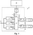
- FIG. 1shows a schematic view of a charger 1 according to the present invention, comprising two power exchange ports 2 , 3 for vehicles 4 , 5 , each port comprising a data communication connection 2 a , 3 a for at least receiving a power request from a vehicle, and a power exchange connection 2 b , 3 b for delivering power to a vehicle; a grid connection 6 for receiving electric power, a data communication bus 7 , for communicating the power request from the vehicles to a plurality of autonomously controllable power converters 8 , 9 , 10 , each for converting power from the grid connection to a suitable level and wave-form for charging a vehicle, wherein each of the power converters comprises a data communication device 8 a , 9 a , 10 a , connected to the data bus 7 , and configured for receiving power requests from vehicles 4 , Sand for indicating its available power via the data bus 7 .
- Data bus 7provides a way to share relevant information from the power modules, vehicle interfaces and backend interface. Information is shared in such a way that these mentioned devices have up to date information. With this information specific choices are being made such as allocation of power modules to vehicle interfaces.
- the data communication connections of the power exchange portsare provided with a data communication device 2 c , 3 c , that is configured for retrieving a power request from a vehicle, making the request available to the controllable power converters via the communication bus 7 and receiving available power indications from the power converters 8 , 9 , 10 .
- the chargerfurther comprises a data storage 11 coupled to the data communication bus 7 , the data storage comprising system limitation data, such as a power limit of the grid connection, peak shaving requirements or energy costs, as well as a communication port 11 a for communication with the back-end of the power grid 12 .
- system limitation datasuch as a power limit of the grid connection, peak shaving requirements or energy costs
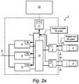
- the data communication devices 2 c , 3 c , 8 a , 9 a , 10 aare configured for determining if at least one power converter has power available for at least partly fulfilling a request from a vehicle, coupling a power output of at least one power converter to a power exchange connection of a power exchange port for a vehicle by means of a matrix with switches 13 if power is available and negotiating power conversion settings with the autonomously controllable power converters in response to a power request from a vehicle.
- the data communication devices 2 c , 3 c , 8 a , 9 a , 10 aare configured for coupling power outputs of available power converters to a power exchange connection until the power request is fulfilled or until no more power converters are available.
- the data communication devices 2 c , 3 c , 8 a , 9 a , 10 aare configured for verifying if there are available power converters after a predetermined time interval or after a predetermined event when a power request was or is more than a maximum power available from a power converter and if there are available power converters, coupling a power output of at least one of such power converters to the power exchange connection of the power exchange port for the vehicle that requests the power.
- FIG. 2shows a block diagram of a method according to the present invention.
- the methodcomprises the steps of determining the sum of power requested by vehicles at power exchange ports of the charger, determining the sum of power available by power converters comprised by the charger, if the sum of the power requested is larger than the sum of the available power, and allocate the available power of at least one power converter to the power exchange port a requesting vehicle is coupled to, such that the power request of said vehicle is met, and determine the remaining sum of power available by power converters comprised by the charger. If the sum of the power requested is larger than the sum of the available power a negotiation with the vehicle is performed and available power of at least one power converter is allocated to the power exchange port a requesting vehicle is coupled to.
- FIGS. 2 a -2 kgive a detailed example of a sequence of practical situations at the charger.
- FIG. 2 ashows an initial situation wherein electric vehicle EV 1 requests maximum DC power from the charger. Vehicle interface 1 sends requests to the power modules and the back-end interface for the available DC power.
- FIG. 2 bshows a situation wherein each of the power is rated to 20 kW and 3 power modules are available.
- a dynamic grid limitis 50 kW, so the available max DC power is 50 kW as well.
- FIG. 2 cshows that electric vehicle EV 1 starts with a DC power demand of 40 kW.
- the vehicle interface 1sends set points to two of the power modules. Electric vehicle EV 1 is charged.
- FIG. 2 dshows that electric vehicle EV 2 arrived later than electric vehicle EV 1 .
- Electric vehicle EV 2requests the maximum DC power from the charger.
- Vehicle interface 2sends requests to the power modules and the back-end interface for the available DC power.
- FIG. 2 eshows that each of the power modules is rated to 20 kW and one power module is available, the others are used by vehicle interface 1 .
- the dynamic grid limitis 50 kW, so the maximum available DC power 10 kW.
- FIG. 2 fshows that electric vehicle EV 2 starts with a DC power demand of 10 kW.
- the vehicle interface 2sends set points to one of the power modules. Electric vehicle EV 2 is charged.
- FIG. 2 gshows that electric vehicle EV 1 and 2 are being charged.
- the power demand of electric vehicle EV 1is decreased to 20 kW, therefore power module 2 is released by vehicle interface 1 .
- Electric vehicle EV 2increases its DC power demand to 30 kW.
- the vehicle interface 2send set points to two of the power modules (PM 2 and PM 3 ). Electric vehicle EV 2 is charged with higher power.
- FIG. 2 jshows that a new limit (60 kW) is received from the back-end server of the grid operator.
- the new limitis synchronized with the vehicles interfaces.
- the maximum available DC power communicated to the vehiclesare 20 kW (EV 1 ) and 40 kW (EV 2 ).
- FIG. 2 kshows that electric vehicle EV 2 increases its DC power demand to 40 kW. Electric vehicle EV 2 is charged with higher power.
Landscapes
- Engineering & Computer Science (AREA)
- Power Engineering (AREA)
- Transportation (AREA)
- Mechanical Engineering (AREA)
- Charge And Discharge Circuits For Batteries Or The Like (AREA)
- Electric Propulsion And Braking For Vehicles (AREA)
- Direct Current Feeding And Distribution (AREA)
- Secondary Cells (AREA)
Abstract
Description
Claims (4)
Priority Applications (2)
| Application Number | Priority Date | Filing Date | Title |
|---|---|---|---|
| US15/875,520US10807485B2 (en) | 2013-11-06 | 2018-01-19 | Charger for electric vehicles with distributed power converter arbitration |
| US16/675,769US11007885B2 (en) | 2013-11-06 | 2019-11-06 | Charger for electric vehicles with distributed power converter arbitration |
Applications Claiming Priority (5)
| Application Number | Priority Date | Filing Date | Title |
|---|---|---|---|
| EP13191822 | 2013-11-06 | ||
| EP13191822.9AEP2871090B1 (en) | 2013-11-06 | 2013-11-06 | Charger for electric vehicles with distributed power converter arbitration |
| EP13191822.9 | 2013-11-06 | ||
| US14/535,018US9908421B2 (en) | 2013-11-06 | 2014-11-06 | Charger for electric vehicles with distributed power converter arbitration |
| US15/875,520US10807485B2 (en) | 2013-11-06 | 2018-01-19 | Charger for electric vehicles with distributed power converter arbitration |
Related Parent Applications (1)
| Application Number | Title | Priority Date | Filing Date |
|---|---|---|---|
| US14/535,018DivisionUS9908421B2 (en) | 2013-11-06 | 2014-11-06 | Charger for electric vehicles with distributed power converter arbitration |
Related Child Applications (1)
| Application Number | Title | Priority Date | Filing Date |
|---|---|---|---|
| US16/675,769DivisionUS11007885B2 (en) | 2013-11-06 | 2019-11-06 | Charger for electric vehicles with distributed power converter arbitration |
Publications (2)
| Publication Number | Publication Date |
|---|---|
| US20180141447A1 US20180141447A1 (en) | 2018-05-24 |
| US10807485B2true US10807485B2 (en) | 2020-10-20 |
Family
ID=49546314
Family Applications (3)
| Application Number | Title | Priority Date | Filing Date |
|---|---|---|---|
| US14/535,018Active2035-11-26US9908421B2 (en) | 2013-11-06 | 2014-11-06 | Charger for electric vehicles with distributed power converter arbitration |
| US15/875,520Active2035-04-29US10807485B2 (en) | 2013-11-06 | 2018-01-19 | Charger for electric vehicles with distributed power converter arbitration |
| US16/675,769ActiveUS11007885B2 (en) | 2013-11-06 | 2019-11-06 | Charger for electric vehicles with distributed power converter arbitration |
Family Applications Before (1)
| Application Number | Title | Priority Date | Filing Date |
|---|---|---|---|
| US14/535,018Active2035-11-26US9908421B2 (en) | 2013-11-06 | 2014-11-06 | Charger for electric vehicles with distributed power converter arbitration |
Family Applications After (1)
| Application Number | Title | Priority Date | Filing Date |
|---|---|---|---|
| US16/675,769ActiveUS11007885B2 (en) | 2013-11-06 | 2019-11-06 | Charger for electric vehicles with distributed power converter arbitration |
Country Status (7)
| Country | Link |
|---|---|
| US (3) | US9908421B2 (en) |
| EP (2) | EP3782846A1 (en) |
| JP (2) | JP6639776B2 (en) |
| CN (1) | CN104638735A (en) |
| ES (1) | ES2837356T3 (en) |
| PL (1) | PL2871090T3 (en) |
| PT (1) | PT2871090T (en) |
Cited By (3)
| Publication number | Priority date | Publication date | Assignee | Title |
|---|---|---|---|---|
| US20220227243A1 (en)* | 2019-05-14 | 2022-07-21 | Chargepoly | System and method for electrically charging motor vehicles |
| US20230117407A1 (en)* | 2021-10-19 | 2023-04-20 | Chargepoint, Inc. | Dynamic allocation of power modules for charging electric vehicles |
| US20230264591A1 (en)* | 2022-02-21 | 2023-08-24 | Cyberswitchingpatents, Llc | Electric vehicle charging master controller |
Families Citing this family (40)
| Publication number | Priority date | Publication date | Assignee | Title |
|---|---|---|---|---|
| US8013570B2 (en) | 2009-07-23 | 2011-09-06 | Coulomb Technologies, Inc. | Electrical circuit sharing for electric vehicle charging stations |
| US9878629B2 (en) | 2009-12-17 | 2018-01-30 | Chargepoint, Inc. | Method and apparatus for electric vehicle charging station load management in a residence |
| PT2871090T (en)* | 2013-11-06 | 2020-12-24 | Abb Schweiz Ag | Charger for electric vehicles with distributed power converter arbitration |
| JP5918330B2 (en)* | 2014-10-01 | 2016-05-18 | 株式会社東光高岳 | Electric mobile charging device |
| US10873212B2 (en) | 2015-05-29 | 2020-12-22 | Hewlett-Packard Development Company, L.P. | Wireless charging at a lower class type |
| EP3314722A4 (en)* | 2015-09-04 | 2019-03-13 | Hewlett-Packard Development Company, L.P. | TRANSFER OF POWER FROM A DATA PORT |
| US20170199834A1 (en)* | 2016-01-13 | 2017-07-13 | Ford Global Technologies, Llc | Vehicle subsystem communication arbitration |
| US10150380B2 (en) | 2016-03-23 | 2018-12-11 | Chargepoint, Inc. | Dynamic allocation of power modules for charging electric vehicles |
| CN107294145A (en)* | 2016-03-30 | 2017-10-24 | 通用电气公司 | charging device, system and method |
| US10744883B2 (en)* | 2016-05-25 | 2020-08-18 | Chargepoint, Inc. | Dynamic allocation of power modules for charging electric vehicles |
| CN106696721B (en)* | 2016-12-16 | 2023-07-04 | 四川新筑通工汽车有限公司 | Dual-source energy system of pure electric vehicle, power supply control method, fast charging method and slow charging method |
| TWI624132B (en)* | 2016-12-27 | 2018-05-11 | 飛宏科技股份有限公司 | Intelligent power distributing system for charging station |
| EP3358698A1 (en)* | 2017-02-02 | 2018-08-08 | University of Limerick | Battery charging |
| CN111032423A (en)* | 2017-07-10 | 2020-04-17 | Abb瑞士股份有限公司 | Variable power charging |
| DE102017116887A1 (en) | 2017-07-26 | 2019-01-31 | Wobben Properties Gmbh | Charging station with dynamic charging current distribution |
| DE102017116886A1 (en) | 2017-07-26 | 2019-01-31 | Wobben Properties Gmbh | Charging station with dynamic charging current distribution |
| CN110014916B (en)* | 2017-09-01 | 2024-07-12 | 珠海银隆电器有限公司 | Vehicle direct-current charging system and method based on energy equalizing charge |
| CN108400634B (en)* | 2018-02-09 | 2021-06-01 | 蔚来(安徽)控股有限公司 | Electric vehicle charging control device and method |
| CN108667095B (en)* | 2018-05-16 | 2024-01-12 | 济南保特电子设备有限公司 | Power management distributor |
| DE102018212740A1 (en)* | 2018-07-31 | 2020-02-06 | Ads-Tec Gmbh | Charging station for electric cars |
| DE102018212927A1 (en)* | 2018-08-02 | 2020-02-06 | Audi Ag | Charger for electric vehicles |
| DE102019121848A1 (en)* | 2019-08-14 | 2021-02-18 | Wobben Properties Gmbh | Method for operating a charging station for electric vehicles |
| CN110435473B (en)* | 2019-08-16 | 2020-09-25 | 山东山大电力技术股份有限公司 | Power switching device, group control charging system and method |
| WO2021050186A1 (en)* | 2019-09-12 | 2021-03-18 | Zayo Group, Llc | Integrated data and charging station |
| CN110901453B (en)* | 2019-11-21 | 2021-01-01 | 科华恒盛股份有限公司 | Output switching control method, device and equipment for multi-gun charging pile and storage medium |
| CN112829627A (en)* | 2019-11-22 | 2021-05-25 | 台达电子企业管理(上海)有限公司 | Power distribution system and method for charging multiple electric vehicles |
| ES2961592T3 (en)* | 2020-04-16 | 2024-03-12 | Chargepoly | Motor vehicle charging system and procedure |
| EP3920356A1 (en)* | 2020-06-02 | 2021-12-08 | ABB Schweiz AG | Electric vehicle charging station |
| CN112124103A (en)* | 2020-10-12 | 2020-12-25 | 江西瑞华智能科技有限公司 | Multi-gun power distribution direct-current charger protection system |
| CN112356728B (en)* | 2020-10-19 | 2022-05-06 | 开迈斯新能源科技有限公司 | Power balance and power module energy efficiency optimization control method for direct current charging pile |
| CN112248867B (en)* | 2020-11-23 | 2022-08-12 | 国网北京市电力公司 | Automobile charging method and system |
| JP7250368B2 (en)* | 2021-01-25 | 2023-04-03 | ブルーネットワークス株式会社 | METHOD FOR CONTROLLING CHARGING CAPACITY OF ELECTRIC VEHICLE CHARGING TERMINAL FOR CHARGING SPECIFIC ELECTRIC VEHICLE, AND SERVER USING THE SAME |
| GB2603902A (en)* | 2021-02-15 | 2022-08-24 | Peter Boxwell Michael | Improved power supply to charging stations for electric vehicles |
| US11554684B2 (en) | 2021-02-17 | 2023-01-17 | AMPLY Power, Inc. | Aggregating capacity for depot charging |
| KR102551423B1 (en)* | 2021-09-15 | 2023-07-06 | 주식회사 효성 | Multi-channel charging system |
| PL246039B1 (en)* | 2022-05-27 | 2024-11-25 | Euroloop Spolka Z Ograniczona Odpowiedzialnoscia | DC charger for electric vehicles |
| CN116101109B (en)* | 2023-04-12 | 2023-06-23 | 深圳市百广源科技有限公司 | Parallel energy storage charging system |
| PL445710A1 (en)* | 2023-07-30 | 2025-02-03 | Energycar Spółka Z Ograniczoną Odpowiedzialnością | Dual-station AC charger, dual-station AC charger network, and method for controlling power transfer in a networked and non-networked charger |
| CN117022025B (en)* | 2023-10-10 | 2023-12-05 | 南京能可瑞科技有限公司 | Charging pile power balance distribution system and method thereof |
| JP2025101929A (en)* | 2023-12-26 | 2025-07-08 | 株式会社日立製作所 | Power management system and power supply system |
Citations (39)
| Publication number | Priority date | Publication date | Assignee | Title |
|---|---|---|---|---|
| US4849682A (en)* | 1987-10-30 | 1989-07-18 | Anton/Bauer, Inc. | Battery charging system |
| US5598084A (en)* | 1993-04-19 | 1997-01-28 | Keith; Arlie L. | Charging batteries of electric vehicles |
| US20040189251A1 (en) | 2003-03-28 | 2004-09-30 | Kutkut Nasser H. | Modular and reconfigurable rapid battery charger |
| US7256516B2 (en) | 2000-06-14 | 2007-08-14 | Aerovironment Inc. | Battery charging system and method |
| US20080039979A1 (en) | 2006-08-10 | 2008-02-14 | V2 Green Inc. | Smart Islanding and Power Backup in a Power Aggregation System for Distributed Electric Resources |
| US20090091291A1 (en) | 2007-10-04 | 2009-04-09 | Gm Global Technology Operations, Inc. | Power grid load management for plug-in vehicles |
| US20100228405A1 (en) | 2007-06-13 | 2010-09-09 | Intrago Corporation | Shared vehicle management system |
| US7844370B2 (en) | 2006-08-10 | 2010-11-30 | Gridpoint, Inc. | Scheduling and control in a power aggregation system for distributed electric resources |
| US20110006603A1 (en)* | 2009-07-10 | 2011-01-13 | Protonex Technology Corporation | Portable power manager operating methods |
| US20110106329A1 (en) | 2009-11-03 | 2011-05-05 | GRIDbot, LLC | Methods and apparatus for charging station with sms user interface |
| US20110115425A1 (en)* | 2009-11-13 | 2011-05-19 | Dresser, Inc. | Recharging Electric Vehicles |
| US20110145141A1 (en) | 2009-10-02 | 2011-06-16 | James Blain | Method and apparatus for recharging electric vehicles |
| US20110285345A1 (en)* | 2010-05-19 | 2011-11-24 | Hitachi, Ltd. | Method of receiving charge, method of controlling charge, charge control unit and charging equipment |
| WO2011145939A2 (en) | 2010-05-19 | 2011-11-24 | Epyon B.V. | Charging system for electric vehicles |
| US8102149B2 (en) | 2007-12-24 | 2012-01-24 | Signet System Inc. | Charger capable of performing integrated control and separate control of parallel operations |
| US20120074893A1 (en) | 2009-12-22 | 2012-03-29 | G2 Llc | Battery charging and management systems and related methods |
| US20120200256A1 (en) | 2011-02-04 | 2012-08-09 | David Yuan Jei Tse | Battery charging station |
| US20120286720A1 (en)* | 2009-09-02 | 2012-11-15 | Jochen Fassnacht | Jump-starting method and device for implementing the method |
| US8378627B2 (en) | 2009-08-05 | 2013-02-19 | Denso Corporation | Electric supply controller, electric supply system and method for controlling electric supply to charger and vehicle |
| US20130057210A1 (en) | 2011-09-02 | 2013-03-07 | Tesla Motors, Inc. | Method of Operating a Multiport Vehicle Charging System |
| US20130069292A1 (en) | 2011-09-15 | 2013-03-21 | Wabtec Holding Corp. | Compressible Elastomeric Spring |
| JP2013070500A (en) | 2011-09-22 | 2013-04-18 | Nissan Motor Co Ltd | Charger and charging method |
| US20130103191A1 (en) | 2010-02-22 | 2013-04-25 | Abb B.V. | System, device and method for exchanging energy with an electric vehicle |
| WO2013100764A1 (en) | 2011-12-29 | 2013-07-04 | Abb B.V. | Method, system and charger for charging a battery of an electric vehicle |
| US20130179061A1 (en) | 2010-06-10 | 2013-07-11 | The Regents Of The University Of California | Smart electric vehicle (ev) charging and grid integration apparatus and methods |
| US20130257146A1 (en)* | 2012-04-03 | 2013-10-03 | Geraldo Nojima | Electric vehicle supply equipment for electric vehicles |
| US20130278225A1 (en)* | 2011-01-15 | 2013-10-24 | Daimler Ag | Method for Charging a Battery of a Vehicle |
| US20130346308A1 (en)* | 2011-10-20 | 2013-12-26 | Panasonic Corporation | Vehicle charging control apparatus, vehicle charging control method, and information terminal |
| US8760115B2 (en) | 2009-08-20 | 2014-06-24 | GM Global Technology Operations LLC | Method for charging a plug-in electric vehicle |
| US8890474B2 (en) | 2010-04-20 | 2014-11-18 | Hanwha Techm Co., Ltd. | Universal charging device |
| US8912753B2 (en) | 2007-10-04 | 2014-12-16 | General Motors Llc. | Remote power usage management for plug-in vehicles |
| US20150061569A1 (en)* | 2013-03-13 | 2015-03-05 | Ideal Power, Inc. | Methods, systems, and devices for improved electric vehicle charging |
| US9000721B2 (en) | 2011-06-29 | 2015-04-07 | General Electric Company | Systems and methods for charging |
| US9248753B2 (en) | 2010-12-03 | 2016-02-02 | Abb B.V. | Method, system and device for charging an electric vehicle |
| US9371008B2 (en) | 2010-03-05 | 2016-06-21 | Abb B.V. | System, devices and method for charging a battery of an electric vehicle |
| US20160185246A1 (en)* | 2013-09-20 | 2016-06-30 | Kabushiki Kaisha Toshiba | Charging management device, charging management system, and charging management method |
| US9637017B2 (en)* | 2013-10-25 | 2017-05-02 | Korea Institute Of Energy Research | Power-sharing charging system, charging device, and method for controlling the same |
| US9908421B2 (en)* | 2013-11-06 | 2018-03-06 | Abb Schweiz Ag | Charger for electric vehicles with distributed power converter arbitration |
| US10137796B2 (en)* | 2014-10-31 | 2018-11-27 | Abb Schweiz Ag | Control system for electric vehicle charging station and method thereof |
Family Cites Families (4)
| Publication number | Priority date | Publication date | Assignee | Title |
|---|---|---|---|---|
| WO2001052475A2 (en)* | 2000-01-14 | 2001-07-19 | Qariba Limited | Resource allocation |
| WO2011118187A1 (en)* | 2010-03-23 | 2011-09-29 | パナソニック株式会社 | Charging control apparatus, charging system, and charging control method |
| WO2012086825A1 (en) | 2010-12-21 | 2012-06-28 | 日本電気株式会社 | Charging device and charging method |
| US8963494B2 (en)* | 2012-05-18 | 2015-02-24 | Tesla Motors, Inc. | Charge rate optimization |
- 2013
- 2013-11-06PTPT131918229Tpatent/PT2871090T/enunknown
- 2013-11-06ESES13191822Tpatent/ES2837356T3/enactiveActive
- 2013-11-06PLPL13191822Tpatent/PL2871090T3/enunknown
- 2013-11-06EPEP20199479.5Apatent/EP3782846A1/enactivePending
- 2013-11-06EPEP13191822.9Apatent/EP2871090B1/enactiveActive
- 2014
- 2014-11-06JPJP2014226267Apatent/JP6639776B2/enactiveActive
- 2014-11-06USUS14/535,018patent/US9908421B2/enactiveActive
- 2014-11-06CNCN201410618428.2Apatent/CN104638735A/enactivePending
- 2018
- 2018-01-19USUS15/875,520patent/US10807485B2/enactiveActive
- 2019
- 2019-10-30JPJP2019197689Apatent/JP7179710B2/enactiveActive
- 2019-11-06USUS16/675,769patent/US11007885B2/enactiveActive
Patent Citations (54)
| Publication number | Priority date | Publication date | Assignee | Title |
|---|---|---|---|---|
| US4849682A (en)* | 1987-10-30 | 1989-07-18 | Anton/Bauer, Inc. | Battery charging system |
| US5598084A (en)* | 1993-04-19 | 1997-01-28 | Keith; Arlie L. | Charging batteries of electric vehicles |
| US7256516B2 (en) | 2000-06-14 | 2007-08-14 | Aerovironment Inc. | Battery charging system and method |
| US20040189251A1 (en) | 2003-03-28 | 2004-09-30 | Kutkut Nasser H. | Modular and reconfigurable rapid battery charger |
| US7135836B2 (en) | 2003-03-28 | 2006-11-14 | Power Designers, Llc | Modular and reconfigurable rapid battery charger |
| US7844370B2 (en) | 2006-08-10 | 2010-11-30 | Gridpoint, Inc. | Scheduling and control in a power aggregation system for distributed electric resources |
| US20080039979A1 (en) | 2006-08-10 | 2008-02-14 | V2 Green Inc. | Smart Islanding and Power Backup in a Power Aggregation System for Distributed Electric Resources |
| US20100228405A1 (en) | 2007-06-13 | 2010-09-09 | Intrago Corporation | Shared vehicle management system |
| US8912753B2 (en) | 2007-10-04 | 2014-12-16 | General Motors Llc. | Remote power usage management for plug-in vehicles |
| US8278881B2 (en)* | 2007-10-04 | 2012-10-02 | GM Global Technology Operations LLC | Power grid load management for plug-in vehicles |
| US20090091291A1 (en) | 2007-10-04 | 2009-04-09 | Gm Global Technology Operations, Inc. | Power grid load management for plug-in vehicles |
| US8102149B2 (en) | 2007-12-24 | 2012-01-24 | Signet System Inc. | Charger capable of performing integrated control and separate control of parallel operations |
| US8633619B2 (en)* | 2009-07-10 | 2014-01-21 | Protonex Technology Corporation | Power managers and methods for operating power managers |
| US20110006603A1 (en)* | 2009-07-10 | 2011-01-13 | Protonex Technology Corporation | Portable power manager operating methods |
| US8378627B2 (en) | 2009-08-05 | 2013-02-19 | Denso Corporation | Electric supply controller, electric supply system and method for controlling electric supply to charger and vehicle |
| US8760115B2 (en) | 2009-08-20 | 2014-06-24 | GM Global Technology Operations LLC | Method for charging a plug-in electric vehicle |
| US9193272B2 (en)* | 2009-09-02 | 2015-11-24 | Robert Bosch Gmbh | Jump-starting method and device for implementing the method |
| US20120286720A1 (en)* | 2009-09-02 | 2012-11-15 | Jochen Fassnacht | Jump-starting method and device for implementing the method |
| US20110145141A1 (en) | 2009-10-02 | 2011-06-16 | James Blain | Method and apparatus for recharging electric vehicles |
| US20110106329A1 (en) | 2009-11-03 | 2011-05-05 | GRIDbot, LLC | Methods and apparatus for charging station with sms user interface |
| US9365127B2 (en)* | 2009-11-13 | 2016-06-14 | Wayne Fueling Systems Llc | Recharging electric vehicles |
| US20110115425A1 (en)* | 2009-11-13 | 2011-05-19 | Dresser, Inc. | Recharging Electric Vehicles |
| US20120074893A1 (en) | 2009-12-22 | 2012-03-29 | G2 Llc | Battery charging and management systems and related methods |
| US20130103191A1 (en) | 2010-02-22 | 2013-04-25 | Abb B.V. | System, device and method for exchanging energy with an electric vehicle |
| US9371008B2 (en) | 2010-03-05 | 2016-06-21 | Abb B.V. | System, devices and method for charging a battery of an electric vehicle |
| US8890474B2 (en) | 2010-04-20 | 2014-11-18 | Hanwha Techm Co., Ltd. | Universal charging device |
| US20130069592A1 (en) | 2010-05-19 | 2013-03-21 | Abb B.V. | Charging system for electric vehicles |
| US20110285345A1 (en)* | 2010-05-19 | 2011-11-24 | Hitachi, Ltd. | Method of receiving charge, method of controlling charge, charge control unit and charging equipment |
| WO2011145939A2 (en) | 2010-05-19 | 2011-11-24 | Epyon B.V. | Charging system for electric vehicles |
| JP2012005341A (en) | 2010-05-19 | 2012-01-05 | Hitachi Ltd | Charger, charge control unit, charge control method, and charge reception method |
| US9168841B2 (en)* | 2010-05-19 | 2015-10-27 | Hitachi, Ltd. | Method of receiving charge, method of controlling charge, charge control unit and charging equipment |
| US9026347B2 (en) | 2010-06-10 | 2015-05-05 | The Regents Of The University Of California | Smart electric vehicle (EV) charging and grid integration apparatus and methods |
| US20130179061A1 (en) | 2010-06-10 | 2013-07-11 | The Regents Of The University Of California | Smart electric vehicle (ev) charging and grid integration apparatus and methods |
| US9248753B2 (en) | 2010-12-03 | 2016-02-02 | Abb B.V. | Method, system and device for charging an electric vehicle |
| US20130278225A1 (en)* | 2011-01-15 | 2013-10-24 | Daimler Ag | Method for Charging a Battery of a Vehicle |
| US8952656B2 (en) | 2011-02-04 | 2015-02-10 | Atieva, Inc. | Battery charging station |
| US20120200256A1 (en) | 2011-02-04 | 2012-08-09 | David Yuan Jei Tse | Battery charging station |
| US9000721B2 (en) | 2011-06-29 | 2015-04-07 | General Electric Company | Systems and methods for charging |
| US20130057210A1 (en) | 2011-09-02 | 2013-03-07 | Tesla Motors, Inc. | Method of Operating a Multiport Vehicle Charging System |
| US20130057209A1 (en) | 2011-09-02 | 2013-03-07 | Tesla Motors, Inc. | Multiport Vehicle DC Charging System with Variable Power Distribution |
| US8810198B2 (en)* | 2011-09-02 | 2014-08-19 | Tesla Motors, Inc. | Multiport vehicle DC charging system with variable power distribution according to power distribution rules |
| US8643330B2 (en) | 2011-09-02 | 2014-02-04 | Tesla Motors, Inc. | Method of operating a multiport vehicle charging system |
| US20130069292A1 (en) | 2011-09-15 | 2013-03-21 | Wabtec Holding Corp. | Compressible Elastomeric Spring |
| JP2013070500A (en) | 2011-09-22 | 2013-04-18 | Nissan Motor Co Ltd | Charger and charging method |
| US20130346308A1 (en)* | 2011-10-20 | 2013-12-26 | Panasonic Corporation | Vehicle charging control apparatus, vehicle charging control method, and information terminal |
| US9881286B2 (en)* | 2011-10-20 | 2018-01-30 | Panasonic Intellectual Property Management Co., Ltd. | Vehicle charging control apparatus, vehicle charging control method, and information terminal |
| WO2013100764A1 (en) | 2011-12-29 | 2013-07-04 | Abb B.V. | Method, system and charger for charging a battery of an electric vehicle |
| US20150165917A1 (en)* | 2011-12-29 | 2015-06-18 | Abb B.V. | Method, system and charger for charging a battery of an electric vehicle |
| US20130257146A1 (en)* | 2012-04-03 | 2013-10-03 | Geraldo Nojima | Electric vehicle supply equipment for electric vehicles |
| US20150061569A1 (en)* | 2013-03-13 | 2015-03-05 | Ideal Power, Inc. | Methods, systems, and devices for improved electric vehicle charging |
| US20160185246A1 (en)* | 2013-09-20 | 2016-06-30 | Kabushiki Kaisha Toshiba | Charging management device, charging management system, and charging management method |
| US9637017B2 (en)* | 2013-10-25 | 2017-05-02 | Korea Institute Of Energy Research | Power-sharing charging system, charging device, and method for controlling the same |
| US9908421B2 (en)* | 2013-11-06 | 2018-03-06 | Abb Schweiz Ag | Charger for electric vehicles with distributed power converter arbitration |
| US10137796B2 (en)* | 2014-10-31 | 2018-11-27 | Abb Schweiz Ag | Control system for electric vehicle charging station and method thereof |
Non-Patent Citations (2)
| Title |
|---|
| European Search Report dated Apr. 2, 2014; European Patent Application No. 13191822.9; 8 pgs. |
| Yutthana Kanthaphayao et al., "Distributed Control of Parallel AC to DC Converter", IEEE Proceedings, Department of Electrical Engineering, University of Technology North Bangkok, Thailand, and Rajamangal University of Technology, Chiang Mai, Thailand, 2009, 8 pgs. |
Cited By (3)
| Publication number | Priority date | Publication date | Assignee | Title |
|---|---|---|---|---|
| US20220227243A1 (en)* | 2019-05-14 | 2022-07-21 | Chargepoly | System and method for electrically charging motor vehicles |
| US20230117407A1 (en)* | 2021-10-19 | 2023-04-20 | Chargepoint, Inc. | Dynamic allocation of power modules for charging electric vehicles |
| US20230264591A1 (en)* | 2022-02-21 | 2023-08-24 | Cyberswitchingpatents, Llc | Electric vehicle charging master controller |
Also Published As
| Publication number | Publication date |
|---|---|
| US11007885B2 (en) | 2021-05-18 |
| JP2020048406A (en) | 2020-03-26 |
| EP3782846A1 (en) | 2021-02-24 |
| US20180141447A1 (en) | 2018-05-24 |
| US20200139827A1 (en) | 2020-05-07 |
| JP2015109790A (en) | 2015-06-11 |
| US20150123613A1 (en) | 2015-05-07 |
| PL2871090T3 (en) | 2021-04-19 |
| JP6639776B2 (en) | 2020-02-05 |
| ES2837356T3 (en) | 2021-06-30 |
| US9908421B2 (en) | 2018-03-06 |
| EP2871090B1 (en) | 2020-10-07 |
| PT2871090T (en) | 2020-12-24 |
| EP2871090A1 (en) | 2015-05-13 |
| JP7179710B2 (en) | 2022-11-29 |
| CN104638735A (en) | 2015-05-20 |
Similar Documents
| Publication | Publication Date | Title |
|---|---|---|
| US11007885B2 (en) | Charger for electric vehicles with distributed power converter arbitration | |
| CN107194530B (en) | Electric vehicle energy scheduling method and system | |
| JP5930431B2 (en) | Power storage system including modularized BMS connection structure and control method thereof | |
| EP3511193A1 (en) | Electric car, and method of providing power charging between electric cars | |
| JP6003930B2 (en) | Power system | |
| JP5533306B2 (en) | Charge control device and charge control method thereof | |
| CN108879831B (en) | Power distribution system, capacity sharing system, master station, slave station, method and equipment | |
| EP2812971B1 (en) | Converter for a battery charging station | |
| JP2015507914A (en) | Method, system and charger for charging a battery of an electric vehicle | |
| CN114056179A (en) | Power control method, system, medium, device and charging station for charging and replacing station | |
| WO2012100538A1 (en) | Communication power source with multi-energy supply and control method thereof | |
| US10326270B2 (en) | DC power transmission device, DC power reception device, and DC power transmission system | |
| EP4427971A1 (en) | Charging system, charging station, power supply method, and computer readable storage medium | |
| WO2024250675A1 (en) | Charging device and power distribution method | |
| KR20210052015A (en) | Electronic device and method for adjusting electric power consumed in electric vehicle charging system | |
| EP2744065B1 (en) | Electric vehicle charging system and electric vehicle charging apparatus | |
| CN116890682A (en) | Power system, power control device, and power control method | |
| US20230191940A1 (en) | Power supply system for powering a home | |
| CN119116758A (en) | Power management method, system, and charging pile | |
| CN120382815A (en) | Charging equipment | |
| JP2024177781A (en) | Power Management System | |
| JP2024503418A (en) | Hybrid charging device for electric vehicles, charging system including the same, and charging method using the same | |
| JP2025008368A (en) | Power Management System |
Legal Events
| Date | Code | Title | Description |
|---|---|---|---|
| FEPP | Fee payment procedure | Free format text:ENTITY STATUS SET TO UNDISCOUNTED (ORIGINAL EVENT CODE: BIG.); ENTITY STATUS OF PATENT OWNER: LARGE ENTITY | |
| AS | Assignment | Owner name:ABB TECHNOLOGY AG, SWITZERLAND Free format text:ASSIGNMENT OF ASSIGNORS INTEREST;ASSIGNORS:KOOLEN, GERARDUS JOHANNES KAREL MARIJKE;ALBERS-VAN-DER-LINDEN, JEAN-PIERRE;BECH, LARS PETER;SIGNING DATES FROM 20141118 TO 20141208;REEL/FRAME:044731/0513 | |
| AS | Assignment | Owner name:ABB SCHWEIZ AG, SWITZERLAND Free format text:MERGER;ASSIGNOR:ABB TECHNOLOGY AG;REEL/FRAME:045204/0158 Effective date:20160617 | |
| STPP | Information on status: patent application and granting procedure in general | Free format text:DOCKETED NEW CASE - READY FOR EXAMINATION | |
| STPP | Information on status: patent application and granting procedure in general | Free format text:NON FINAL ACTION MAILED | |
| STPP | Information on status: patent application and granting procedure in general | Free format text:NON FINAL ACTION MAILED | |
| STPP | Information on status: patent application and granting procedure in general | Free format text:NON FINAL ACTION MAILED | |
| STPP | Information on status: patent application and granting procedure in general | Free format text:RESPONSE TO NON-FINAL OFFICE ACTION ENTERED AND FORWARDED TO EXAMINER | |
| STPP | Information on status: patent application and granting procedure in general | Free format text:NOTICE OF ALLOWANCE MAILED -- APPLICATION RECEIVED IN OFFICE OF PUBLICATIONS | |
| STCF | Information on status: patent grant | Free format text:PATENTED CASE | |
| AS | Assignment | Owner name:ABB B.V., NETHERLANDS Free format text:ASSIGNMENT OF ASSIGNORS INTEREST;ASSIGNOR:ABB SCHWEIZ AG;REEL/FRAME:062205/0860 Effective date:20221010 | |
| AS | Assignment | Owner name:ABB E-MOBILITY B.V., NETHERLANDS Free format text:CHANGE OF NAME;ASSIGNOR:ABB B.V.;REEL/FRAME:062320/0490 Effective date:20220101 | |
| MAFP | Maintenance fee payment | Free format text:PAYMENT OF MAINTENANCE FEE, 4TH YEAR, LARGE ENTITY (ORIGINAL EVENT CODE: M1551); ENTITY STATUS OF PATENT OWNER: LARGE ENTITY Year of fee payment:4 |