US10806891B2 - Method for infusing stem cells - Google Patents
Method for infusing stem cellsDownload PDFInfo
- Publication number
- US10806891B2 US10806891B2US16/174,689US201816174689AUS10806891B2US 10806891 B2US10806891 B2US 10806891B2US 201816174689 AUS201816174689 AUS 201816174689AUS 10806891 B2US10806891 B2US 10806891B2
- Authority
- US
- United States
- Prior art keywords
- infusion
- catheter
- fluid medium
- cells
- liquid
- Prior art date
- Legal status (The legal status is an assumption and is not a legal conclusion. Google has not performed a legal analysis and makes no representation as to the accuracy of the status listed.)
- Active
Links
Images


Classifications
- A—HUMAN NECESSITIES
- A61—MEDICAL OR VETERINARY SCIENCE; HYGIENE
- A61M—DEVICES FOR INTRODUCING MEDIA INTO, OR ONTO, THE BODY; DEVICES FOR TRANSDUCING BODY MEDIA OR FOR TAKING MEDIA FROM THE BODY; DEVICES FOR PRODUCING OR ENDING SLEEP OR STUPOR
- A61M25/00—Catheters; Hollow probes
- A61M25/0021—Catheters; Hollow probes characterised by the form of the tubing
- A61M25/0023—Catheters; Hollow probes characterised by the form of the tubing by the form of the lumen, e.g. cross-section, variable diameter
- A—HUMAN NECESSITIES
- A61—MEDICAL OR VETERINARY SCIENCE; HYGIENE
- A61L—METHODS OR APPARATUS FOR STERILISING MATERIALS OR OBJECTS IN GENERAL; DISINFECTION, STERILISATION OR DEODORISATION OF AIR; CHEMICAL ASPECTS OF BANDAGES, DRESSINGS, ABSORBENT PADS OR SURGICAL ARTICLES; MATERIALS FOR BANDAGES, DRESSINGS, ABSORBENT PADS OR SURGICAL ARTICLES
- A61L29/00—Materials for catheters, medical tubing, cannulae, or endoscopes or for coating catheters
- A61L29/14—Materials characterised by their function or physical properties, e.g. lubricating compositions
- A61L29/16—Biologically active materials, e.g. therapeutic substances
- A—HUMAN NECESSITIES
- A61—MEDICAL OR VETERINARY SCIENCE; HYGIENE
- A61M—DEVICES FOR INTRODUCING MEDIA INTO, OR ONTO, THE BODY; DEVICES FOR TRANSDUCING BODY MEDIA OR FOR TAKING MEDIA FROM THE BODY; DEVICES FOR PRODUCING OR ENDING SLEEP OR STUPOR
- A61M25/00—Catheters; Hollow probes
- A61M25/0067—Catheters; Hollow probes characterised by the distal end, e.g. tips
- A61M25/0068—Static characteristics of the catheter tip, e.g. shape, atraumatic tip, curved tip or tip structure
- A61M25/0071—Multiple separate lumens
- A—HUMAN NECESSITIES
- A61—MEDICAL OR VETERINARY SCIENCE; HYGIENE
- A61M—DEVICES FOR INTRODUCING MEDIA INTO, OR ONTO, THE BODY; DEVICES FOR TRANSDUCING BODY MEDIA OR FOR TAKING MEDIA FROM THE BODY; DEVICES FOR PRODUCING OR ENDING SLEEP OR STUPOR
- A61M25/00—Catheters; Hollow probes
- A61M25/0067—Catheters; Hollow probes characterised by the distal end, e.g. tips
- A61M25/0074—Dynamic characteristics of the catheter tip, e.g. openable, closable, expandable or deformable
- A61M25/0075—Valve means
- A—HUMAN NECESSITIES
- A61—MEDICAL OR VETERINARY SCIENCE; HYGIENE
- A61L—METHODS OR APPARATUS FOR STERILISING MATERIALS OR OBJECTS IN GENERAL; DISINFECTION, STERILISATION OR DEODORISATION OF AIR; CHEMICAL ASPECTS OF BANDAGES, DRESSINGS, ABSORBENT PADS OR SURGICAL ARTICLES; MATERIALS FOR BANDAGES, DRESSINGS, ABSORBENT PADS OR SURGICAL ARTICLES
- A61L2300/00—Biologically active materials used in bandages, wound dressings, absorbent pads or medical devices
- A61L2300/60—Biologically active materials used in bandages, wound dressings, absorbent pads or medical devices characterised by a special physical form
- A61L2300/64—Animal cells
- A—HUMAN NECESSITIES
- A61—MEDICAL OR VETERINARY SCIENCE; HYGIENE
- A61L—METHODS OR APPARATUS FOR STERILISING MATERIALS OR OBJECTS IN GENERAL; DISINFECTION, STERILISATION OR DEODORISATION OF AIR; CHEMICAL ASPECTS OF BANDAGES, DRESSINGS, ABSORBENT PADS OR SURGICAL ARTICLES; MATERIALS FOR BANDAGES, DRESSINGS, ABSORBENT PADS OR SURGICAL ARTICLES
- A61L2400/00—Materials characterised by their function or physical properties
- A61L2400/06—Flowable or injectable implant compositions
- A—HUMAN NECESSITIES
- A61—MEDICAL OR VETERINARY SCIENCE; HYGIENE
- A61M—DEVICES FOR INTRODUCING MEDIA INTO, OR ONTO, THE BODY; DEVICES FOR TRANSDUCING BODY MEDIA OR FOR TAKING MEDIA FROM THE BODY; DEVICES FOR PRODUCING OR ENDING SLEEP OR STUPOR
- A61M5/00—Devices for bringing media into the body in a subcutaneous, intra-vascular or intramuscular way; Accessories therefor, e.g. filling or cleaning devices, arm-rests
- A61M5/14—Infusion devices, e.g. infusing by gravity; Blood infusion; Accessories therefor
- A61M2005/1401—Functional features
- A61M2005/1404—Keep vein-open rate [KVO], i.e. low flow rate
- A—HUMAN NECESSITIES
- A61—MEDICAL OR VETERINARY SCIENCE; HYGIENE
- A61M—DEVICES FOR INTRODUCING MEDIA INTO, OR ONTO, THE BODY; DEVICES FOR TRANSDUCING BODY MEDIA OR FOR TAKING MEDIA FROM THE BODY; DEVICES FOR PRODUCING OR ENDING SLEEP OR STUPOR
- A61M25/00—Catheters; Hollow probes
- A61M25/01—Introducing, guiding, advancing, emplacing or holding catheters
- A61M2025/0183—Rapid exchange or monorail catheters
- A—HUMAN NECESSITIES
- A61—MEDICAL OR VETERINARY SCIENCE; HYGIENE
- A61M—DEVICES FOR INTRODUCING MEDIA INTO, OR ONTO, THE BODY; DEVICES FOR TRANSDUCING BODY MEDIA OR FOR TAKING MEDIA FROM THE BODY; DEVICES FOR PRODUCING OR ENDING SLEEP OR STUPOR
- A61M25/00—Catheters; Hollow probes
- A61M25/10—Balloon catheters
- A61M2025/1043—Balloon catheters with special features or adapted for special applications
- A61M2025/1097—Balloon catheters with special features or adapted for special applications with perfusion means for enabling blood circulation only while the balloon is in an inflated state, e.g. temporary by-pass within balloon
- A—HUMAN NECESSITIES
- A61—MEDICAL OR VETERINARY SCIENCE; HYGIENE
- A61M—DEVICES FOR INTRODUCING MEDIA INTO, OR ONTO, THE BODY; DEVICES FOR TRANSDUCING BODY MEDIA OR FOR TAKING MEDIA FROM THE BODY; DEVICES FOR PRODUCING OR ENDING SLEEP OR STUPOR
- A61M39/00—Tubes, tube connectors, tube couplings, valves, access sites or the like, specially adapted for medical use
- A61M39/08—Tubes; Storage means specially adapted therefor
- A61M2039/085—Tubes; Storage means specially adapted therefor external enteral feeding tubes
- A—HUMAN NECESSITIES
- A61—MEDICAL OR VETERINARY SCIENCE; HYGIENE
- A61M—DEVICES FOR INTRODUCING MEDIA INTO, OR ONTO, THE BODY; DEVICES FOR TRANSDUCING BODY MEDIA OR FOR TAKING MEDIA FROM THE BODY; DEVICES FOR PRODUCING OR ENDING SLEEP OR STUPOR
- A61M2205/00—General characteristics of the apparatus
- A61M2205/33—Controlling, regulating or measuring
- A61M2205/3331—Pressure; Flow
- A61M2205/3334—Measuring or controlling the flow rate
- A—HUMAN NECESSITIES
- A61—MEDICAL OR VETERINARY SCIENCE; HYGIENE
- A61M—DEVICES FOR INTRODUCING MEDIA INTO, OR ONTO, THE BODY; DEVICES FOR TRANSDUCING BODY MEDIA OR FOR TAKING MEDIA FROM THE BODY; DEVICES FOR PRODUCING OR ENDING SLEEP OR STUPOR
- A61M2206/00—Characteristics of a physical parameter; associated device therefor
- A61M2206/10—Flow characteristics
- A61M2206/18—Coaxial flows, e.g. one flow within another
- A—HUMAN NECESSITIES
- A61—MEDICAL OR VETERINARY SCIENCE; HYGIENE
- A61M—DEVICES FOR INTRODUCING MEDIA INTO, OR ONTO, THE BODY; DEVICES FOR TRANSDUCING BODY MEDIA OR FOR TAKING MEDIA FROM THE BODY; DEVICES FOR PRODUCING OR ENDING SLEEP OR STUPOR
- A61M25/00—Catheters; Hollow probes
- A61M25/10—Balloon catheters
- A61M25/1002—Balloon catheters characterised by balloon shape
- A—HUMAN NECESSITIES
- A61—MEDICAL OR VETERINARY SCIENCE; HYGIENE
- A61M—DEVICES FOR INTRODUCING MEDIA INTO, OR ONTO, THE BODY; DEVICES FOR TRANSDUCING BODY MEDIA OR FOR TAKING MEDIA FROM THE BODY; DEVICES FOR PRODUCING OR ENDING SLEEP OR STUPOR
- A61M39/00—Tubes, tube connectors, tube couplings, valves, access sites or the like, specially adapted for medical use
- A61M39/10—Tube connectors; Tube couplings
- A61M39/105—Multi-channel connectors or couplings, e.g. for connecting multi-lumen tubes
Definitions
- the present inventionpertains generally to infusion systems for introducing particles into a fluid stream. More particularly, the present invention pertains to infusion systems for introducing (infusing) particles of biological matter (e.g. stem cells) into the vasculature of a patient without diminishing the therapeutic effectiveness of the biological matter.
- biological mattere.g. stem cells
- the present inventionis particularly, but not exclusively useful as a system using a multi-lumen filter that allows particles to enter a lumen of the separator, either individually or in small groupings, for subsequent infusion into the vasculature of a patient.
- intravascular therapyi.e. intracoronary, intra-arterial or intravenous
- the therapeutic agente.g. biologics or drugs
- the diameter of a fluid passagewayis a factor that will affect the rate of fluid flow through the passageway.
- the diameter of the passagewaymust obviously be large enough to individually accommodate the small groups of particles.
- itmust also be small enough to separate and prevent larger groups of particles (cells) from clinging to each other.
- the rate at which particles can be carried through the passagewaywill be circumscribed by the dimensions of the passageway.
- a further consequence of thisis that, as particles leave the passageway, they are then influenced by the flow of fluid (i.e. blood) in the vessel of the vasculature. Depending on the purpose of the protocol, this may mean that the downstream fluid flow in the vasculature will somehow also need to be regulated.
- the downstream fluid flow in the vasculaturecan be controlled or regulated using an inflatable balloon that is attached to an outside surface of the catheter tube.
- an inflatable balloonthat is attached to an outside surface of the catheter tube.
- the catheter tubeis typically made of a flexible material to allow it to twist and turn as the catheter is navigated through the patient's vasculature. Because of the flexible nature of the catheter tube, it is typically susceptible to kinking and/or collapse during inflation of the balloon. This can be particularly troublesome for infusion catheters where the material to be infused is pumped through a central lumen of the catheter tube.
- a collapse or even partial blocking of the central lumen where the balloon is inflatedcan impede fluid flow in the central lumen, and adversely affect an infusion procedure.
- a collapsed or blocked catheter tube lumencan reduce cell viability during transport through the lumen by exposing the cells to shear stress (Note: in some cases, viability has been found to be lowered by around 70-80% when flow is impeded in the central lumen).
- shear stress thresholdFor each type of cell or cell family, there is a shear stress threshold which must be avoided to prevent cell injury. For some types of cells, exposure to stresses above a maximum shear stress is sufficient to avoid damage. For other types of cells, both the magnitude of the shear stresses and the time the cell is exposed to the shear stress must be considered when establishing the shear stress threshold.
- a number of factorscan influence the shear stress levels that develop when a fluid medium having a suspension of cells is pumped through an infusion catheter and introduced into the vasculature of a patient. These factors can include the size and geometry of the internal passages in the catheter, the concentration and type of cells present in the fluid medium and the flow rate.
- the use of a multi-lumen separator in an infusion cathetercan, in some cases, affect the levels of shear stress that are developed within the catheter.
- an inflation ballooncan in some cases, affect the size and geometry of the internal passages in the catheter, which in turn, can affect the levels of shear stress that are developed.
- an object of the present inventionto provide an infusion system that can effectively introduce only small groups of particles into a fluid flow.
- Another object of the present inventionis to provide an infusion system that coordinates the flow rate of a particle/fluid medium (i.e. a first fluid) with the flow rate of a fluid (i.e. a second fluid) into which the particle/fluid medium is being introduced.
- Still another object of the present inventionis to provide an infusion system that produces a low exit pressure to reduce the impact on a vessel wall caused when fluid exits a catheter and enters the vessel.
- It is still another object of the present inventionto provide an infusion system having a balloon to regulate blood flow at an infusion site that is not subject to central lumen collapse or blocking during balloon inflation.
- an infusion systemincludes an elongated catheter which is formed with a central lumen that extends between the proximal and distal ends of the catheter.
- the catheteris tubular shaped with a smooth, circular, outer surface and, for purposes of description, the catheter defines a longitudinal axis.
- a source of a fluid medium having particles suspended thereini.e. a particle/fluid medium
- a separatoris connected at the distal end of the catheter.
- the separatoris provided to prevent the particles from flocculating as they are infused or introduced into a vessel in the vasculature of a patient.
- the particlescan be either biologics (i.e. cell, gene or protein) or drugs. And, they can be introduced into the vasculature for intracoronary, intra-arterial, or intravenous therapy.
- the separatoris formed with a plurality of parallel lumens.
- each lumen of the separatoris individually placed in fluid communication with the central lumen of the catheter.
- each individual lumenis dimensioned to sequentially receive only small groups of particles (i.e. less than ten) therethrough.
- each lumencan receive several particles at a time, each lumen is sufficiently small to effectively separate particles from clinging to each other as they are received into the lumen.
- the systemalso includes a means for moving the particle/fluid medium through the lumen of the catheter, for further movement of the particles in alignment through individual lumens of the separator.
- the means for moving this particle/fluid mediumcan be any such means well known in the pertinent art, such as an IV pole, a syringe, or a pump.
- the system of the present inventionalso includes a configurable (inflatable) valve, such as a balloon.
- the configurable valveis positioned on the outer surface of the catheter to surround the catheter at a location that is proximal to the separator.
- the valveis formed with a plurality of apertures that are arranged around the axis of the catheter. The purpose of these apertures is to control the axial movement of a fluid (e.g. blood) past the catheter in a distal direction substantially parallel to the axis of the catheter.
- This controlis preferably provided by an inflator that selectively constricts the apertures of the valve to control the flow rate of fluid through the apertures.
- the valveis formed as an annulus that is centered on the axis.
- the annulushas an inner diameter that is affixed to the outer surface of the catheter.
- the valvealso has a substantially non-compliant material positioned on the outer periphery of the annulus that maintains the outer diameter at a predetermined radial distance from the catheter when the valve is inflated into a base configuration.
- the valvecan be a balloon as commonly used in the pertinent art, and the balloon can be of any material appropriate for this type of procedure.
- the balloonmay be nylon, polyethylene, or polyethylene terephthalate (PET).
- PETpolyethylene terephthalate
- the rest of the annulusis made of a compliant material.
- this compliant materialis responsive to the inflator to selectively constrict the apertures.
- Additional features of the present inventioninclude a provision for positioning the catheter in the vasculature over a monorail type guide wire. Also, a fluid flow controller can be provided to meter fluid flow from the source into the central lumen of the catheter at a selected fluid pressure.
- a recollection chamber used during an intravenous or an arterial infusionis provided at the distal end of the catheter and is created by positioning the separator in the central lumen of the catheter at a distance d from the distal end of the catheter. With this positioning, the recollection chamber will be substantially tubular, it will have a length d, and it will have a diameter the same as that of the central lumen. It should be noted that the valve, or balloon, does not extend to this location near the distal end of the catheter.
- the proximal (upstream) surfaceis slanted at an angle ⁇ relative to the axis of the catheter.
- the angle ⁇will be around 60°, with a consequence that the lumens established by the separator will have different lengths.
- the proximal (upstream) surface of the separatorwill be flat, with the entrance to each lumen angled at the angle ⁇ from the axis of the catheter.
- this surfacewill have a stepped configuration so that the entrance to each lumen will be perpendicular to the axis of the catheter.
- the distal (downstream) surface of the catheterwill be perpendicular to the axis of the catheter.
- the separator and the recollection chamberfunction to promote and maintain the separation of biologics as they are being safely infused.
- the recollection chamberslows the fluid velocity rate of the infusion fluid, after it has been accelerated through the separator.
- an inflatable ballooncan be attached to the outer surface of the catheter and it can be selectively inflated to coordinate the respective rates of blood flow and fluid infusion.
- a reinforcing memberis employed to strengthen the catheter wall under the inflatable balloon.
- the catheterdoes not kink or collapse due to the pressure exerted on the catheter wall when the balloon is inflated. Instead, a substantially constant cross-section for the central lumen is maintained during an inflation of the balloon, allowing for the unimpeded flow of particles to pass through the central lumen during an infusion of particles into a patient's vasculature.
- the reinforcement memberis positioned in contact with a section of the catheter wall that encircles a portion of the central lumen. Specifically, the reinforcement member is positioned in contact with the catheter wall under the inflatable balloon.
- the reinforcement membercomprises an annular shaped ring that is affixed to the outer surface of the catheter wall under the inflatable balloon. With the annular shaped ring affixed, the ring is oriented substantially perpendicular to a longitudinal axis defined by the infusion catheter and concentric with the axis, to strengthen the catheter wall.
- a separatoracts as both a filter and the reinforcement member.
- the separatoris located under the inflatable balloon and positioned in contact with the inner surface of the wall.
- the separatorprovides the dual function of preventing particles from flocculating as they are infused into the vasculature and functions to strengthen the catheter wall to prevent collapse during balloon inflation.
- a method for infusing a liquid into the vasculature of a patientincludes the steps of supplying a source of the liquid and providing an infusion catheter.
- the infusion catheterhas a proximal end and a distal end and is formed with a multi-lumen infusion unit mounted adjacent the distal end of the infusion catheter.
- the infusion catheterincludes an inflation balloon that is affixed to the catheter at a location that is proximal to the multi-lumen infusion unit.
- the distal end of the inflation catheteris positioned in an artery of the vasculature of the patient at a location within a predetermined distance from an intended target tissue surface.
- the balloonis inflated to at least partially occlude the artery.
- a forceis exerted on the liquid to establish a flow rate for the liquid in the catheter. Specifically, the force is exerted to infuse the liquid from the catheter through the infusion unit and into the vasculature with a homogeneous distribution of the liquid to cover the intended surface of the target tissue.
- the flow ratecan be established in accordance with an infusion protocol that is characterized by time and liquid volume parameters based on viscosity and pressure values in the liquid.
- the forcecan be exerted on the liquid in accordance with the infusion protocol to provide a substantially constant shear-stress distribution in the liquid during an infusion.
- the forcecan be exerted on the liquid in accordance with the infusion protocol to provide a substantially homogeneous distribution of elements suspended in the liquid during an infusion.
- FIG. 1is a schematic/perspective view of the system of the present invention shown with the system catheter positioned in an operational environment;
- FIG. 2is a cross-section view of the separator and distal portion of the system catheter as seen along the line 2 - 2 in FIG. 1 ;
- FIG. 3is a cross-section view of an alternate embodiment of the infusion tip as seen along line 2 - 2 in FIG. 1 ;
- FIG. 4is a cross-section view of an alternate embodiment of the infusion tip shown in FIG. 3 ;
- FIG. 5Ais a plan view of the balloon of the present invention in a deflated configuration and shown with the catheter positioned in an operational environment;
- FIG. 5Bis a plan view of the balloon of the present invention in an inflated configuration and shown with the system catheter positioned in an operational environment;
- FIG. 6is a plan view of the venous catheter for the present invention.
- FIG. 7is a cross-section view of an alternate embodiment of an infusion tip as seen along line 2 - 2 in FIG. 1 , having a balloon for regulating/controlling the axial movement of a fluid (e.g. blood) past the catheter and a separator which also functions to prevent catheter tube collapse during balloon inflation, shown with the balloon in a deflated state;
- a fluide.g. blood
- FIG. 8is a cross-section view of the infusion tip shown in FIG. 7 , shown with the balloon in an inflated state;
- FIG. 9is a cross-section view of an alternate embodiment of an infusion tip as seen along line 2 - 2 in FIG. 1 , having a balloon for regulating/controlling the axial movement of a fluid (e.g. blood) past the catheter and an annular shaped ring to prevent catheter tube collapse during balloon inflation, shown with the balloon in a deflated state;
- a fluide.g. blood
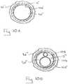
- FIG. 10is a cross-section view of the infusion tip shown in FIG. 9 , shown with the balloon in an inflated state;
- FIG. 10Ais a cross-section view of the infusion tip embodiment shown in FIG. 9 , as seen along line 10 A- 10 A;
- FIG. 10Bis a cross-section view as in FIG. 10A showing another infusion tip embodiment having an inflation tube and infusion tube within the central lumen of the catheter;
- FIG. 11is a flow-chart illustrating a protocol for infusing cells, such as stem cells, which ensures that stresses exerted on the cells are maintained below a shear stress threshold specified for the type of cell to prevent cell damage during an infusion procedure.
- a system for introducing (infusing) a fluid in accordance with the present inventionis shown and is generally designated 10 .
- the system 10includes a catheter 12 that can be advanced into a vessel 14 to position the catheter 10 at a predetermined location in the vasculature of a patient (not shown).
- the vessel 14is preferably an artery or a vein in the cardiovascular system of a patient, and the system 10 is used for an intra-arterial, intravenous or intracoronary protocol.
- FIG. 1shows that the system 10 includes a source 16 for holding a fluid medium 18 .
- a plurality of particles 20are suspended in the fluid medium 18 to create a particle/fluid medium 22 .
- the particles 20may be some form of a drug or, most likely, they will be some form of a biologics (i.e. cell, gene or protein).
- the particles 20will be suspended in the particle/fluid medium 22 for transport from the source 16 through the system 10 and into the vessel 14 .
- the source 16can be a syringe of a type well known in the pertinent art.
- the system 10includes a controller 24 that is in fluid communication with the source 16 .
- the controller 24can be any type device that is known in the pertinent art for moving a fluid (e.g. the particle/fluid medium 22 ) through a fluid flow system (e.g. system 10 ).
- a fluid flow systeme.g. system 10
- such a devicemay be an IV pump, an IV pole, a syringe, or some other fluid flow metering apparatus.
- the source 16is a syringe
- there is no specific need for a controller 24there is no specific need for a controller 24 .
- FIG. 1also shows that the system 10 includes an inflator 26 for a purpose to be discussed below.
- the controller 24 and the inflator 26can be individually joined at a connector 28 to, respectively, establish separate fluid communication channels with the catheter 12 .
- this connector 28is connected in fluid communication with the proximal end 30 of the catheter 12 .
- the system 10includes a tip (filter) 32 (hereinafter sometimes also referred to as a separator 68 ) that is affixed to the distal end 34 of the catheter 12 .
- a valve 36is mounted on the catheter 12 proximal the distal end 34 , and that the valve 36 is formed with a plurality of apertures, of which the apertures 38 a and 38 b are exemplary.
- the actual construction of the distal portion of the catheter 12 , and the cooperation of structure between the separator 68 and the valve 36will perhaps be best appreciated with reference to FIG. 2 .
- the separator 68is formed with a plurality of lumens, of which the lumens 40 a , 40 b , and 40 c are exemplary. More specifically, the lumens extend axially through the separator 68 and are substantially parallel to each other. They are also substantially parallel to the axis 42 that is generally defined by the catheter 12 . Importantly, each lumen is established with a diameter 44 that is specifically dimensioned to receive only individual or small groups of particles 20 . Although each lumen can receive several de-flocculated particles 20 at a time, the individual particles 20 or small groups of particles remain separated while they transit the lumen (e.g. see lumen 40 a ). Further, the separator 68 can be formed with a monorail lumen 46 that will interact with a guide wire 48 , in a manner well known by the skilled artisan, for the purpose of positioning the catheter 12 within the vessel 14 .
- the diameter 44 of each lumenbe dimensioned to prevent the entry of large groups of flocculated particles 20 into the lumen from the central lumen 50 of the catheter 12 .
- the particles 20may be dispersed as they enter the vessel 14 , to thereby minimize the possibility of subsequent flocculation in the vessel 14 , which may lead to heart attack or stroke if the cells are infused into the coronary circulatory system.
- dispersion of the particles 20 as they enter the vessel 14will provide better mixing with the blood for more efficient distribution to tissue.
- the valve 36is formed with a plurality of apertures. Further, with cross reference to FIG. 1 and FIG. 2 , it will also be appreciated that, when inflated, the valve 36 is generally shaped as an annulus and is formed with an inflation chamber 52 . As shown, the inflation chamber 52 is connected in fluid communication with the inflator 26 via an inflation line 54 . Within this structure, the inflation line 54 can be integrated into the catheter 12 .
- the valve 36includes a valve body 56 that is made of a compliant, inflatable material.
- the valve 36also includes a rim 58 made of a substantially non-compliant material that is located on the periphery of the annulus shaped valve 36 .
- the valve 36is located proximal to the separator 68 , and it is affixed to the outer surface 60 of the catheter 12 by any means known in the pertinent art, such as by gluing or bonding.
- the valve 36(balloon) starts from a deflated configuration, and it is then inflated by the inflator 26 into a base configuration (see FIGS. 1 and 2 ) wherein the valve 36 is constrained by the rim 58 .
- the valve 36will extend from the surface 60 of catheter 12 through a radial distance 62 and, in the base configuration, it will most likely make contact with the vessel 14 .
- each aperturee.g. aperture 38 a
- the rim 58does not expand from the base configuration.
- the radial distance 62remains substantially constant.
- valve body 56will expand in response to the inflator 26 such that the apertures are incrementally constricted. Stated differently, and with specific reference to the aperture 38 a , the diameter 64 will be diminished. In an alternate embodiment for the present invention, there may be no need for the valve 36 .
- a guide wire 48is first prepositioned in the vasculature of a patient.
- the guide wire 48is then received into the monorail lumen 46 of the catheter 12 , and the catheter 12 is advanced over the guide wire 48 and into position in the vasculature of the patient.
- the valve 36is inflated into its base configuration, or beyond. The exact extent of inflation for valve 36 will depend on the desired flow rate for fluid through the apertures in the vessel 14 . With the valve 36 inflated, the controller 24 is then activated to cause a flow of particle/fluid medium 22 from the source 16 and through the central lumen 50 of the catheter 12 .
- the respective diameters 44 of individual lumens in the separator 68allow only individual particles 20 or small groups of particles 20 to enter the lumen.
- the flocculation of particles 20 in the central lumen 50is disrupted, and flocculation of the particles 20 after they have passed through the separator 68 is minimized.
- the system 10is appropriate for any use wherein particles 20 may be suspended in a particle/fluid medium 22 for subsequent release as individual particle 20 into a fluid flow (e.g. blood flow through a vessel 14 ).
- an infusion tip for biologicsis shown and generally is designated 66 .
- a separator 68 ′is located in the central lumen 50 of the catheter 12 at a distance d from the distal end 34 of the catheter 12 .
- the separator 68 ′creates a recollection chamber 70 having a length d at the distal end 34 of the catheter 12 .
- the recollection chamber 70is a tubular section formed onto the distal end 34 of the catheter 12 . If necessary, the recollection chamber 70 may be established by a stand-alone piece of tubing that can be attached to the distal end 34 of the catheter 12 .
- the separator 68 ′has a proximal (upstream) surface 72 and a distal (downstream) surface 74 .
- the proximal surface 72 of the separator 68 ′is oriented at a slant angle ⁇ relative to the axis 42 of the catheter 12 .
- the distal surface 74 of the separator 68 ′is perpendicular to the axis 42 , and it is substantially flat.
- each lumen 76 a - cwill also be slanted at angle ⁇ relative to the axis 42 of catheter 12 . Consequently, when fluid flows through the catheter 12 and encounters the slanted proximal surface 72 of the catheter 12 , it is redirected to flow through the lumens 76 a - c of the separator 68 ′. In operation, this redirection helps prevent particles 20 in the fluid from flocculating prior to entering the vasculature of the patient. Upon exiting the lumens 76 a - c of the separator 68 ′, the fluid enters the recollection chamber 70 where it is allowed to slow down before entering the vasculature of the patient.
- the guide wire exit lumen 78is formed onto the catheter 12 at a location approximately 25-30 millimeters proximal the separator 68 ′ and 68 ′′.
- FIG. 4a variation of the infusion tip 66 ′ is shown wherein the proximal surface 72 of the separator 68 ′′ is formed with a step configuration. Due to the step configuration, the proximal end of each lumen 80 a - c remains substantially perpendicular to the axis 42 of the catheter 12 .
- the infusion tips 66 , 66 ′ shown in FIGS. 3 and 4are the same with the exception that the proximal surfaces differ.
- the proximal surface 72 of the separator 68can also take the shape shown in FIG. 2 for the separator 32 / 68 .
- a selectively inflatable balloon 82is shown attached to the catheter 12 at a location proximal the separator 68 .
- the balloon 82 ′controls the flow rate of blood around the catheter 12 by expanding radially away from the catheter 12 towards the vessel wall 84 .
- the flow rate of the blood outside the catheter 12should be compatible with the flow rate of fluid inside the catheter 12 in order to minimize turbulence at the distal end 34 of the catheter 12 .
- the overall objective for the recollection chamber 70 and the inflatable balloon 82is to decrease the probability of damage or injury to the vasculature of the patient during an infusion by decreasing the flow rate of blood to allow particles additional time to diffuse and to travel through blood vessels and into the tissue to be treated.
- an infusion tip 66 in accordance with the present inventioncan be employed in a venous catheter 86 of a type that is well-known in the pertinent art. If a venous catheter 86 is used, the infusion tip 66 will be essentially the same as disclosed above for other embodiments. The advantage here is that, in appropriate situations, the venous catheter 86 may be secured to the patient prior to the release of fluid from the fluid source 16 . For example, the wings 90 a - b are secured to the patient prior to the release of fluid 18 from the fluid source 16 . In all other important respects, the operation of the venous catheter 86 with the infusion tip 66 of the present invention is identical to the operation disclosed previously.
- FIG. 7shows another embodiment of an infusion tip 66 ′′ having an elongated catheter 12 ′ having a tubular-shaped wall 92 with an inner surface 94 and an outer surface 96 .
- the inner surface 94 of the wall 92surrounds a central lumen 50 ′ for the catheter 12 ′.
- FIG. 7also shows that an inflatable balloon 82 ′′ is mounted on the outer wall 96 .
- An inflation lumen 98is provided to selectively inflate the balloon 82 ′′ (inflated balloon 82 ′′ shown in FIG. 8 ). It can be seen that a portion of the outer wall 96 cooperates with the balloon 82 ′′ to establish an inflation chamber 100 .
- an inflation fluidis pumped through the inflation lumen 98 , for example using the inflator 26 shown in FIG. 1 and described above, to establish a preselected inflation pressure in the inflation chamber 100 . It is to be appreciated that this pressure will establish a force on the wall 92 that is directed radially inward and tends to constrict or collapse the catheter 12 ′. As indicated above, collapse or constriction of the catheter 12 ′ can undesirably impede flow in the central lumen and/or stress cells such as stem cells in the central lumen flow lowering cell viability (sometimes by as much as 70-80%).
- FIG. 7shows that the infusion tip 66 ′′ can include a reinforcing member 102 to support the catheter wall 92 under the inflatable balloon 82 ′′.
- the reinforcing member 102is a separator 68 ′ (as described above with reference to FIG. 3 ) that is positioned in the central lumen 50 ′ under the balloon 82 ′′.
- the separator 32 / 68 shown in FIG. 2 , the separator 68 ′′ shown in FIG. 4 or a similar separatormay be positioned in the central lumen 50 ′ under the balloon 82 ′′ to reinforce the wall 92 during inflation of the balloon 82 ′′.
- the reinforcing member 102prevents collapse of the wall 92 and maintains a substantially constant cross-section for the central lumen 50 ′ during an inflation of the balloon 82 ′′, allowing for unimpeded fluid flow to pass through the central lumen 50 ′ during an infusion.
- the infusion tip 66 ′′can be advanced to a treatment site suitable for delivery of particles 20 with the balloon 82 ′′ in a deflated state (as shown in FIG. 7 ).
- the balloon 82 ′′is selectively inflated (as shown in FIG. 8 ) to control and/or regulate the flow of blood in the vasculature for blood flowing past the infusion tip 66 ′′.
- a particle/fluid medium 22 including particles 20can be introduced into the central lumen 50 ′ and passed through the separator 68 ′ to prevent large, flocculated particles from entering the bloodstream.
- the particle/fluid medium 22then passes through a recollection chamber 70 ′ and exits the distal end 34 ′ of the catheter 12 ′.
- the balloon 82 ′′can be deflated and the infusion tip 66 ′′ withdrawn from the patient's vasculature.
- FIGS. 9, 10 and 10Ashow another embodiment of an infusion tip 66 ′′′ for an elongated catheter 12 ′′ having a tubular-shaped wall 92 ′ (see FIG. 9 ) with an inner surface 94 ′ and an outer surface 96 ′. As shown, the inner surface 94 ′ of the wall 92 ′ surrounds a central lumen 50 ′′ for the catheter 12 ′′.
- FIG. 7also shows that an inflatable balloon 82 ′′′ is mounted on the outer wall 96 ′.
- An inflation lumen 98 ′is provided to selectively inflate the balloon 82 ′′′ (inflated balloon 82 ′′′ shown in FIG. 10 ).
- a portion of the outer wall 96 ′cooperates with the balloon 82 ′′′ to establish an inflation chamber 100 ′.
- an inflation fluidis pumped through the inflation lumen 98 ′, for example using the inflator 26 shown in FIG. 1 and described above, to establish a preselected inflation pressure in the inflation chamber 100 ′.
- this pressurewill establish a force on the wall 92 ′ that is directed radially inward and tends to constrict or collapse the catheter 12 ′′.
- collapse or constriction of the catheter 12 ′′can undesirably impede flow in the central lumen and/or stress cells such as stem cells in the central lumen flow lowering cell viability (sometimes by as much as 70-80%).
- FIG. 9shows that the infusion tip 66 ′′ can include a reinforcing member 102 ′ to support the catheter wall 92 ′ under the inflatable balloon 82 ′′.
- the reinforcing member 102 ′can be formed as an annular shaped ring that is affixed to the outer surface 96 ′ of the catheter wall 94 ′ under the balloon 82 ′′. Once affixed, the ring shaped reinforcing member 102 ′ is oriented substantially perpendicular to a longitudinal axis 42 ′ defined by the infusion catheter 12 ′′, as shown.
- the reinforcing member 102 ′prevents collapse of the wall 92 ′ and maintains a substantially constant cross-section for the central lumen 50 ′′ during an inflation of the balloon 82 ′′′, allowing for unimpeded fluid flow to pass through the central lumen 50 ′′ during an infusion.
- the infusion tip 66 ′′′can be advanced to a treatment site suitable for delivery of particles 20 with the balloon 82 ′′′ in a deflated state (as shown in FIG. 9 ).
- the balloon 82 ′′′is selectively inflated (as shown in FIG. 10 ) to control and/or regulate the flow of blood in the vasculature for blood flowing past the infusion tip 66 ′′.
- a particle/fluid medium 22 including particles 20can be introduced into the central lumen 50 ′′ and passed through the separator 68 ′ to prevent large, flocculated particles from entering the bloodstream.
- the separator 32 / 68 shown in FIG. 2 , the separator 68 ′′ shown in FIG. 4 , or a similar separatormay be used.
- the particle/fluid medium 22then passes through a recollection chamber 70 ′′ and exits the distal end 34 ′′ of the catheter 12 ′′.
- the balloon 82 ′′′can be deflated and the infusion tip 66 ′′′ withdrawn from the patient's vasculature.
- FIG. 10Bshows another infusion tip embodiment having an inflation tube 104 and an infusion tube 106 positioned within the central lumen 50 ′′′ of the catheter 12 ′′′.
- an inflatable balloon 82 ′′′is mounted on the catheter 12 ′′′, and is connected in fluid communication with the inflatable balloon 82 ′′′.
- a reinforcing member 102 ′′is provided to support the catheter 12 ′′′. Collapse of the catheter 12 ′′′ during inflation may constrict the infusion tube 106 and undesirably impede flow in the infusion tube 106 and/or stress cells, such as stem cells in the infusion tube 106 , lowering cell viability.
- the reinforcing member 102 ′′can be formed as an annular shaped ring that is affixed to the outer surface of the catheter 12 ′′′ under the balloon 82 ′′′.
- FIG. 11shows a protocol 108 for infusing cells, such as stem cells, which ensures that stresses exerted on the cells are maintained below a shear stress threshold specified for the specific type of cell to prevent cell damage during an infusion procedure.
- the protocolbegins by selecting a type of cell or cell family for infusion into the vasculature of a patient during a treatment procedure (Box 110 ).
- a shear stress parameter threshold below which the cells remain viableis determined (Box 112 ). For example, this determination can be made experimentally.
- the shear stress parametercan be a maximum shear stress.
- both the magnitude of the shear stresses and the time the cell is exposed to the shear stresscan be considered when establishing the shear stress threshold.
- an infusion catheteris selected (Box 114 ).
- the infusion cathetercan include internal multi-lumen separator to de-flocculate cells, such as the separator 68 ′ shown in FIG. 10 , and/or an inflation balloon, such as the balloon 82 ′′′ shown in FIG. 10 .
- the size, shape and arrangement of the internal passages in the infusion cathetermay affect the shear stresses developed for a fluid flowing through the catheter.
- these changescan be considered in the protocol 108 when estimating the shear stresses that develop for a fluid flowing through the catheter.
- Box 116shows that a cell concentration for the fluid medium and a flow rate for the fluid medium through the infusion catheter can be selected with the understanding that each of these selections may affect the shear stresses developed for a fluid flowing through the catheter.
- the concentration of cells in the fluidcan affect the fluid's viscosity, which in turn, can affect the flow of the fluid through the catheter and ultimately the shear stresses that develop for a fluid flowing through the catheter.
- a shear stress parametercan be measured or calculated and compared with the shear stress threshold determined in Box 112 . If the measured or calculated shear stress parameter exceeds the shear stress threshold determined in Box 112 , arrow 120 indicates that a new cell concentration and flow rate is then selected (Box 116 ). This selection (Box 116 ) and comparison (Box 118 ) can be repeated, as needed, until the measured or calculated shear stress parameter does not exceed the shear stress threshold determined in Box 112 .
- a distal end of the infusion cathetercan be positioned in an artery of the vasculature of the patient at a location within a predetermined distance from an intended target tissue surface.
- Box 124indicates that the next step in the protocol 108 is to inflate the catheter balloon to at least partially occlude the artery. In this manner, blood flow past the distal end of the catheter can be reduced to increase the efficacy of the infusion procedure.
- Box 126shows that a force can then be exerted on the fluid to establish the selected flow rate for the fluid in the catheter to infuse the fluid into the vasculature.
- a suitable flow rates for the liquidare in the range of 3 milliliters/minute to 12 milliliters/minute and a suitable concentration of stem cells in the liquid is in the range of about 4 ⁇ 10 6 cells/milliliter to about 6 ⁇ 10 6 cells/milliliter.
Landscapes
- Health & Medical Sciences (AREA)
- Life Sciences & Earth Sciences (AREA)
- Animal Behavior & Ethology (AREA)
- General Health & Medical Sciences (AREA)
- Biomedical Technology (AREA)
- Engineering & Computer Science (AREA)
- Veterinary Medicine (AREA)
- Public Health (AREA)
- Heart & Thoracic Surgery (AREA)
- Anesthesiology (AREA)
- Hematology (AREA)
- Biophysics (AREA)
- Pulmonology (AREA)
- Chemical & Material Sciences (AREA)
- Epidemiology (AREA)
- Molecular Biology (AREA)
- Medicinal Chemistry (AREA)
- External Artificial Organs (AREA)
- Vascular Medicine (AREA)
Abstract
Description
Claims (19)
Priority Applications (2)
| Application Number | Priority Date | Filing Date | Title |
|---|---|---|---|
| US16/174,689US10806891B2 (en) | 2009-09-21 | 2018-10-30 | Method for infusing stem cells |
| US17/073,820US20210031002A1 (en) | 2009-09-21 | 2020-10-19 | Method for infusing stem cells |
Applications Claiming Priority (5)
| Application Number | Priority Date | Filing Date | Title |
|---|---|---|---|
| US12/563,876US8647311B2 (en) | 2009-09-21 | 2009-09-21 | Biologics infusion system |
| US13/473,988US8790298B2 (en) | 2009-09-21 | 2012-05-17 | Infusion catheter tip for biologics |
| US14/145,158US10058675B2 (en) | 2009-09-21 | 2013-12-31 | Infusion catheter tip for biologics with reinforced external balloon valve |
| US14/199,490US10155099B2 (en) | 2009-09-21 | 2014-03-06 | Method for infusing stem cells |
| US16/174,689US10806891B2 (en) | 2009-09-21 | 2018-10-30 | Method for infusing stem cells |
Related Parent Applications (1)
| Application Number | Title | Priority Date | Filing Date |
|---|---|---|---|
| US14/199,490DivisionUS10155099B2 (en) | 2009-09-21 | 2014-03-06 | Method for infusing stem cells |
Related Child Applications (1)
| Application Number | Title | Priority Date | Filing Date |
|---|---|---|---|
| US17/073,820DivisionUS20210031002A1 (en) | 2009-09-21 | 2020-10-19 | Method for infusing stem cells |
Publications (2)
| Publication Number | Publication Date |
|---|---|
| US20190060611A1 US20190060611A1 (en) | 2019-02-28 |
| US10806891B2true US10806891B2 (en) | 2020-10-20 |
Family
ID=51208277
Family Applications (3)
| Application Number | Title | Priority Date | Filing Date |
|---|---|---|---|
| US14/199,490Active2031-11-08US10155099B2 (en) | 2009-09-21 | 2014-03-06 | Method for infusing stem cells |
| US16/174,689ActiveUS10806891B2 (en) | 2009-09-21 | 2018-10-30 | Method for infusing stem cells |
| US17/073,820AbandonedUS20210031002A1 (en) | 2009-09-21 | 2020-10-19 | Method for infusing stem cells |
Family Applications Before (1)
| Application Number | Title | Priority Date | Filing Date |
|---|---|---|---|
| US14/199,490Active2031-11-08US10155099B2 (en) | 2009-09-21 | 2014-03-06 | Method for infusing stem cells |
Family Applications After (1)
| Application Number | Title | Priority Date | Filing Date |
|---|---|---|---|
| US17/073,820AbandonedUS20210031002A1 (en) | 2009-09-21 | 2020-10-19 | Method for infusing stem cells |
Country Status (1)
| Country | Link |
|---|---|
| US (3) | US10155099B2 (en) |
Cited By (1)
| Publication number | Priority date | Publication date | Assignee | Title |
|---|---|---|---|---|
| US20210031002A1 (en)* | 2009-09-21 | 2021-02-04 | Cook Regentec Llc | Method for infusing stem cells |
Families Citing this family (2)
| Publication number | Priority date | Publication date | Assignee | Title |
|---|---|---|---|---|
| US10058675B2 (en) | 2009-09-21 | 2018-08-28 | Cook Regentec Llc | Infusion catheter tip for biologics with reinforced external balloon valve |
| AU2015225718B2 (en)* | 2014-03-06 | 2019-12-12 | Cook Regentec Llc | Method for infusing stem cells |
Citations (78)
| Publication number | Priority date | Publication date | Assignee | Title |
|---|---|---|---|---|
| US4465481A (en) | 1981-02-26 | 1984-08-14 | Innovative Surgical Products, Inc. | Single piece wound drain catheter |
| US4608984A (en) | 1980-10-17 | 1986-09-02 | Fogarty Thomas J | Self-retracting dilatation catheter |
| JPS62122675A (en) | 1985-11-22 | 1987-06-03 | 住友ベークライト株式会社 | Medical guide tube and its use |
| EP0266957A2 (en) | 1986-11-04 | 1988-05-11 | C.R. Bard, Inc. | Two balloons angiplasty catheter |
| EP0318918A2 (en) | 1987-12-01 | 1989-06-07 | Terumo Kabushiki Kaisha | Balloon cathether |
| US4848344A (en) | 1987-11-13 | 1989-07-18 | Cook, Inc. | Balloon guide |
| US5000734A (en) | 1988-02-01 | 1991-03-19 | Georges Boussignac | Probe intended to be introduced within a living body |
| US5156594A (en) | 1990-08-28 | 1992-10-20 | Scimed Life Systems, Inc. | Balloon catheter with distal guide wire lumen |
| US5328470A (en) | 1989-03-31 | 1994-07-12 | The Regents Of The University Of Michigan | Treatment of diseases by site-specific instillation of cells or site-specific transformation of cells and kits therefor |
| US5354279A (en) | 1992-10-21 | 1994-10-11 | Bavaria Medizin Technologie Gmbh | Plural needle injection catheter |
| WO1995005868A1 (en) | 1993-08-27 | 1995-03-02 | Siemens Pacesetter, Inc. | Programming system for a patient's cardiac signal |
| US5447497A (en) | 1992-08-06 | 1995-09-05 | Scimed Life Systems, Inc | Balloon catheter having nonlinear compliance curve and method of using |
| US5447797A (en) | 1992-08-10 | 1995-09-05 | Siemens Aktiengesellschaft | Reaction resin mixture comprising epoxy resin, benzylthiolanium salt and sensitizer |
| JPH0838607A (en) | 1994-06-17 | 1996-02-13 | Trudell Medical Ltd | Atomizing catheter device,its use,and its production |
| WO1996012518A1 (en) | 1994-10-20 | 1996-05-02 | Children's Medical Center Corporation | Systems and methods for promoting tissue growth |
| WO1996033756A1 (en) | 1995-04-28 | 1996-10-31 | Medtronic, Inc. | Bioretentive filtered infusion catheter |
| EP0761252A1 (en) | 1995-09-06 | 1997-03-12 | Kabushiki Kaisha Vayu | A perfusion catheter |
| US5707358A (en) | 1996-05-13 | 1998-01-13 | Wright; John T. M. | Dual concentric balloon catheter for retrograde cardioplegia perfusion |
| WO1998048884A2 (en) | 1997-05-01 | 1998-11-05 | Chase Medical Inc. | Aortic arch occlusion and perfusion balloon catheter having pressure ports |
| WO1999025421A1 (en) | 1997-11-18 | 1999-05-27 | Advanced Cardiovascular Systems, Inc. | Perfusion catheter with coil supported inner tubular member |
| US5913842A (en)* | 1991-07-16 | 1999-06-22 | Heartport, Inc. | Retrograde delivery catheter and method for inducing cardioplegic arrest |
| US6048332A (en) | 1998-10-09 | 2000-04-11 | Ave Connaught | Dimpled porous infusion balloon |
| JP2000300524A (en) | 1999-04-16 | 2000-10-31 | Aisin Seiki Co Ltd | Balloon catheter |
| WO2000067647A1 (en) | 1999-05-07 | 2000-11-16 | Boston Scientific Limited | Injection array apparatus and method |
| WO2001034208A1 (en) | 1999-11-05 | 2001-05-17 | The Regents Of The University Of California | Techniques and compositions for treating cardiovascular disease by in vivo gene delivery |
| US6293920B1 (en) | 1994-05-27 | 2001-09-25 | Heartport, Inc. | Catheter system and method for providing cardiopulmonary bypass pump support during heart surgery |
| US6312374B1 (en) | 1997-03-06 | 2001-11-06 | Progenix, Llc | Radioactive wire placement catheter |
| US6319248B1 (en) | 1998-07-29 | 2001-11-20 | Cryocath Technologies, Inc. | Spray catheter |
| US6394978B1 (en) | 2000-08-09 | 2002-05-28 | Advanced Cardiovascular Systems, Inc. | Interventional procedure expandable balloon expansion enabling system and method |
| US20020072647A1 (en) | 2000-12-12 | 2002-06-13 | Schock Robert B. | Intra-aortic balloon catheter having a dual sensor pressure sensing system |
| US20020188276A1 (en) | 2000-01-25 | 2002-12-12 | Bacchus Vascular, Inc. | Apparatus and methods for clot dissolution |
| US6500145B1 (en) | 2000-02-08 | 2002-12-31 | California Medical Laboratories, Inc. | Retrograde cardioplegia catheter |
| US6524302B2 (en) | 2001-04-26 | 2003-02-25 | Scimed Life Systems, Inc. | Multi-lumen catheter |
| US6579287B2 (en) | 2001-10-09 | 2003-06-17 | Cryocath Technologies Inc. | Cryosurgical ablation device having sequential injection and method therefor |
| US20030130610A1 (en)* | 2002-12-09 | 2003-07-10 | Mager Larry F. | Aortic balloon catheter with improved positioning and balloon stability |
| US20030204171A1 (en) | 2000-05-19 | 2003-10-30 | John Kucharczyk | Cell delivery catheter and method |
| US6805860B1 (en) | 2001-09-30 | 2004-10-19 | Eckhard Alt | Method of transluminal application of myogenic cells for repair or replacement of heart tissue |
| US20050059930A1 (en) | 2003-09-16 | 2005-03-17 | Michi Garrison | Method and apparatus for localized drug delivery |
| US20050059931A1 (en) | 2003-09-16 | 2005-03-17 | Venomatrix | Methods and apparatus for localized and semi-localized drug delivery |
| US20050079161A1 (en) | 2001-09-30 | 2005-04-14 | Scicotec Gmbh | Transluminal application of adult stem cells for body organ tissue repair |
| US20050131386A1 (en) | 2003-12-15 | 2005-06-16 | Freeman Lynetta J. | Method and device for minimally invasive implantation of biomaterial |
| US20050226855A1 (en) | 2001-09-30 | 2005-10-13 | Scicotec Gmbh | Method and instrumentation for control of stem cell injection into the body |
| US20050287125A1 (en)* | 2002-05-22 | 2005-12-29 | Medtronic, Inc. | Cell delivery fluid for prevention of cell settling in delivery system |
| US20060004316A1 (en) | 2004-07-02 | 2006-01-05 | Difiore Attilio E | Reduction of recirculation in catheters |
| US20060030814A1 (en) | 2002-09-20 | 2006-02-09 | Flowmedica, Inc. | Method and apparatus for selective drug infusion via an intra-aortic flow diverter delivery catheter |
| US20060074399A1 (en) | 2004-10-05 | 2006-04-06 | Bates Mark C | Methods and apparatus for treating infarcted regions of tissue following acute myocardial infarction |
| WO2006078884A2 (en) | 2004-04-21 | 2006-07-27 | Acclarent, Inc. | Devices, systems and methods for treating disorders of the ear, nose and throat |
| US20070106208A1 (en) | 2005-11-04 | 2007-05-10 | Medrad, Inc. | Delivery of agents to tissue |
| JP2007175497A (en) | 2005-12-22 | 2007-07-12 | Cordis Corp | Guidewire having a distal expansion feature and method for improving the delivery and traversal capabilities of a medical device |
| US20080039786A1 (en) | 2006-08-10 | 2008-02-14 | Boston Scientific Scimed, Inc. | Medical device for vessel compatibility during high pressure infusion |
| WO2008020967A2 (en) | 2006-08-08 | 2008-02-21 | Peak Biosciences, Inc. | Catheter and array for anticancer therapy |
| WO2008057370A2 (en) | 2006-11-01 | 2008-05-15 | Ut-Battelle, Llc | Means and methods for cytometric therapies |
| JP2009522010A (en) | 2005-12-28 | 2009-06-11 | エーエムエス リサーチ コーポレイション | Apparatus, system and related methods for delivering fluid to tissue |
| US20090157042A1 (en) | 2007-12-12 | 2009-06-18 | Boston Scientific Scimed, Inc. | Methods, devices and compositions for controlled drug delivery to injured myocardium |
| US20090192450A1 (en) | 2004-04-22 | 2009-07-30 | Medtronic, Inc. | Branching catheter systems with diagnostic components |
| US20090209630A1 (en) | 2000-10-20 | 2009-08-20 | Vical Incorporated | Gene delivery formulations and methods for treatment of ischemic conditions |
| US20100004593A1 (en) | 2006-09-13 | 2010-01-07 | Boston Scientific Scimed, Inc. | Balloon catheter |
| US7686781B2 (en) | 2001-10-25 | 2010-03-30 | Emory University | Catheter for modified perfusion |
| US20100234804A1 (en) | 2006-06-30 | 2010-09-16 | Katsuhiro Hiejima | Indwelling Needle with wings |
| WO2011035182A2 (en) | 2009-09-21 | 2011-03-24 | Nabil Dib | Biologics infusion system |
| US20110105960A1 (en) | 2009-10-06 | 2011-05-05 | Wallace Michael P | Ultrasound-enhanced Stenosis therapy |
| US20110270131A1 (en) | 2010-04-28 | 2011-11-03 | Allergan, Inc. | Method and system for determining the pressure of a fluid in a syringe, an access port, a catheter, and a gastric band |
| EP2389973A1 (en) | 2010-05-25 | 2011-11-30 | Asahi Intecc Co., Ltd. | Balloon catheter |
| EP2389974A1 (en) | 2010-05-25 | 2011-11-30 | Miracor Medical Systems GmbH | A balloon catheter for introduction into a body vessel, in particular the coronary sinus |
| US20110295114A1 (en) | 2009-12-02 | 2011-12-01 | Renovorx | Devices, methods and kits for delivery of therapeutic materials to a pancreas |
| US20110295302A1 (en) | 2010-05-25 | 2011-12-01 | Miracor Medical Systems Gmbh | Treating Heart Tissue |
| US20110319917A1 (en) | 2007-10-17 | 2011-12-29 | Mindframe, Inc. | Methods of managing neurovascular obstructions |
| US20120035595A1 (en) | 2009-04-09 | 2012-02-09 | Oliver Goedje | Urethral catheter for measuring the pressure inside the bladder of a living being |
| US20120041359A1 (en) | 2010-02-19 | 2012-02-16 | Cardiovascular Systems, Inc. | Systems and methods for mixing therapeutic agents before and/or during administration |
| US20120148668A1 (en) | 2005-06-29 | 2012-06-14 | Advanced Cardiovascular Systems Inc. | Intracoronary device and method of use thereof |
| US20120226225A1 (en)* | 2009-09-21 | 2012-09-06 | Nabil Dib | Infusion Catheter Tip for Biologics |
| US20120245521A1 (en) | 2011-02-25 | 2012-09-27 | Microvention, Inc. | Reinforced Balloon Catheter |
| WO2013173166A1 (en) | 2012-05-17 | 2013-11-21 | Translational Biologic Infusion Catheter, Llc | Infusion catheter tip for biologics |
| WO2013184782A2 (en) | 2012-06-05 | 2013-12-12 | Muffin Incorporated | Catheter systems and methods useful for cell therapy |
| US20140114239A1 (en) | 2009-09-21 | 2014-04-24 | Translational Biologic Infusion Catheter, Llc | Infusion Catheter Tip for Biologics with Reinforced External Balloon Valve |
| US20140207107A1 (en) | 2009-09-21 | 2014-07-24 | Translational Biologic Infusion Catheter, Llc | Method for infusing stem cells |
| WO2015102820A2 (en) | 2013-12-31 | 2015-07-09 | Translational Biologic Infusion Catheter, Llc | Infusion catheter tip for biologics with reinforced external balloon valve |
| US20170073309A1 (en) | 2012-07-17 | 2017-03-16 | Glaxosmithkline Intellectual Property (No. 2) Limited | Chemical Compounds |
Family Cites Families (2)
| Publication number | Priority date | Publication date | Assignee | Title |
|---|---|---|---|---|
| GB9317539D0 (en) | 1993-08-24 | 1993-10-06 | Shiu Man F | Catheter |
| US6840920B2 (en) | 2003-05-09 | 2005-01-11 | Visual Connections | Butterfly needle with passive guard |
- 2014
- 2014-03-06USUS14/199,490patent/US10155099B2/enactiveActive
- 2018
- 2018-10-30USUS16/174,689patent/US10806891B2/enactiveActive
- 2020
- 2020-10-19USUS17/073,820patent/US20210031002A1/ennot_activeAbandoned
Patent Citations (101)
| Publication number | Priority date | Publication date | Assignee | Title |
|---|---|---|---|---|
| US4608984A (en) | 1980-10-17 | 1986-09-02 | Fogarty Thomas J | Self-retracting dilatation catheter |
| US4465481A (en) | 1981-02-26 | 1984-08-14 | Innovative Surgical Products, Inc. | Single piece wound drain catheter |
| JPS62122675A (en) | 1985-11-22 | 1987-06-03 | 住友ベークライト株式会社 | Medical guide tube and its use |
| EP0266957A2 (en) | 1986-11-04 | 1988-05-11 | C.R. Bard, Inc. | Two balloons angiplasty catheter |
| JPS63177868A (en) | 1986-11-04 | 1988-07-22 | シー・アール・バード・インコーポレーテッド | Expansible catheter |
| US4848344A (en) | 1987-11-13 | 1989-07-18 | Cook, Inc. | Balloon guide |
| EP0318918A2 (en) | 1987-12-01 | 1989-06-07 | Terumo Kabushiki Kaisha | Balloon cathether |
| US5000734A (en) | 1988-02-01 | 1991-03-19 | Georges Boussignac | Probe intended to be introduced within a living body |
| US5328470A (en) | 1989-03-31 | 1994-07-12 | The Regents Of The University Of Michigan | Treatment of diseases by site-specific instillation of cells or site-specific transformation of cells and kits therefor |
| US5156594A (en) | 1990-08-28 | 1992-10-20 | Scimed Life Systems, Inc. | Balloon catheter with distal guide wire lumen |
| US5913842A (en)* | 1991-07-16 | 1999-06-22 | Heartport, Inc. | Retrograde delivery catheter and method for inducing cardioplegic arrest |
| US5447497A (en) | 1992-08-06 | 1995-09-05 | Scimed Life Systems, Inc | Balloon catheter having nonlinear compliance curve and method of using |
| US5447797A (en) | 1992-08-10 | 1995-09-05 | Siemens Aktiengesellschaft | Reaction resin mixture comprising epoxy resin, benzylthiolanium salt and sensitizer |
| US5354279A (en) | 1992-10-21 | 1994-10-11 | Bavaria Medizin Technologie Gmbh | Plural needle injection catheter |
| WO1995005868A1 (en) | 1993-08-27 | 1995-03-02 | Siemens Pacesetter, Inc. | Programming system for a patient's cardiac signal |
| US6293920B1 (en) | 1994-05-27 | 2001-09-25 | Heartport, Inc. | Catheter system and method for providing cardiopulmonary bypass pump support during heart surgery |
| JPH0838607A (en) | 1994-06-17 | 1996-02-13 | Trudell Medical Ltd | Atomizing catheter device,its use,and its production |
| US5964223A (en) | 1994-06-17 | 1999-10-12 | Trudell Medical Limited | Nebulizing catheter system and methods of use and manufacture |
| WO1996012518A1 (en) | 1994-10-20 | 1996-05-02 | Children's Medical Center Corporation | Systems and methods for promoting tissue growth |
| JPH11504233A (en) | 1995-04-28 | 1999-04-20 | メドトロニック・インコーポレーテッド | Infusion catheter with bioretentive filter |
| WO1996033756A1 (en) | 1995-04-28 | 1996-10-31 | Medtronic, Inc. | Bioretentive filtered infusion catheter |
| JPH0970441A (en) | 1995-09-06 | 1997-03-18 | Buaayu:Kk | Perfusion catheter |
| EP0761252A1 (en) | 1995-09-06 | 1997-03-12 | Kabushiki Kaisha Vayu | A perfusion catheter |
| US5707358A (en) | 1996-05-13 | 1998-01-13 | Wright; John T. M. | Dual concentric balloon catheter for retrograde cardioplegia perfusion |
| US6312374B1 (en) | 1997-03-06 | 2001-11-06 | Progenix, Llc | Radioactive wire placement catheter |
| WO1998048884A3 (en) | 1997-05-01 | 1999-01-28 | Chase Medical Inc | Aortic arch occlusion and perfusion balloon catheter having pressure ports |
| WO1998048884A2 (en) | 1997-05-01 | 1998-11-05 | Chase Medical Inc. | Aortic arch occlusion and perfusion balloon catheter having pressure ports |
| WO1999025421A1 (en) | 1997-11-18 | 1999-05-27 | Advanced Cardiovascular Systems, Inc. | Perfusion catheter with coil supported inner tubular member |
| US6319248B1 (en) | 1998-07-29 | 2001-11-20 | Cryocath Technologies, Inc. | Spray catheter |
| US6048332A (en) | 1998-10-09 | 2000-04-11 | Ave Connaught | Dimpled porous infusion balloon |
| JP2000300524A (en) | 1999-04-16 | 2000-10-31 | Aisin Seiki Co Ltd | Balloon catheter |
| WO2000067647A1 (en) | 1999-05-07 | 2000-11-16 | Boston Scientific Limited | Injection array apparatus and method |
| US20040138622A1 (en) | 1999-05-07 | 2004-07-15 | Maria Palasis | Injection array apparatus |
| JP2002543868A (en) | 1999-05-07 | 2002-12-24 | ボストン サイエンティフィック リミテッド | Injection array device and method |
| WO2001034208A1 (en) | 1999-11-05 | 2001-05-17 | The Regents Of The University Of California | Techniques and compositions for treating cardiovascular disease by in vivo gene delivery |
| US20110046542A1 (en) | 2000-01-25 | 2011-02-24 | Bacchus Vascular Inc. | Apparatus and methods for clot dissolution |
| US20020188276A1 (en) | 2000-01-25 | 2002-12-12 | Bacchus Vascular, Inc. | Apparatus and methods for clot dissolution |
| US6500145B1 (en) | 2000-02-08 | 2002-12-31 | California Medical Laboratories, Inc. | Retrograde cardioplegia catheter |
| US20030204171A1 (en) | 2000-05-19 | 2003-10-30 | John Kucharczyk | Cell delivery catheter and method |
| US6394978B1 (en) | 2000-08-09 | 2002-05-28 | Advanced Cardiovascular Systems, Inc. | Interventional procedure expandable balloon expansion enabling system and method |
| US20090209630A1 (en) | 2000-10-20 | 2009-08-20 | Vical Incorporated | Gene delivery formulations and methods for treatment of ischemic conditions |
| US20020072647A1 (en) | 2000-12-12 | 2002-06-13 | Schock Robert B. | Intra-aortic balloon catheter having a dual sensor pressure sensing system |
| US6524302B2 (en) | 2001-04-26 | 2003-02-25 | Scimed Life Systems, Inc. | Multi-lumen catheter |
| US6805860B1 (en) | 2001-09-30 | 2004-10-19 | Eckhard Alt | Method of transluminal application of myogenic cells for repair or replacement of heart tissue |
| US20050079161A1 (en) | 2001-09-30 | 2005-04-14 | Scicotec Gmbh | Transluminal application of adult stem cells for body organ tissue repair |
| US20050226855A1 (en) | 2001-09-30 | 2005-10-13 | Scicotec Gmbh | Method and instrumentation for control of stem cell injection into the body |
| US6579287B2 (en) | 2001-10-09 | 2003-06-17 | Cryocath Technologies Inc. | Cryosurgical ablation device having sequential injection and method therefor |
| US7686781B2 (en) | 2001-10-25 | 2010-03-30 | Emory University | Catheter for modified perfusion |
| US20050287125A1 (en)* | 2002-05-22 | 2005-12-29 | Medtronic, Inc. | Cell delivery fluid for prevention of cell settling in delivery system |
| US20060030814A1 (en) | 2002-09-20 | 2006-02-09 | Flowmedica, Inc. | Method and apparatus for selective drug infusion via an intra-aortic flow diverter delivery catheter |
| US20030130610A1 (en)* | 2002-12-09 | 2003-07-10 | Mager Larry F. | Aortic balloon catheter with improved positioning and balloon stability |
| US20050059931A1 (en) | 2003-09-16 | 2005-03-17 | Venomatrix | Methods and apparatus for localized and semi-localized drug delivery |
| US20050059930A1 (en) | 2003-09-16 | 2005-03-17 | Michi Garrison | Method and apparatus for localized drug delivery |
| JP2005194272A (en) | 2003-12-15 | 2005-07-21 | Ethicon Endo Surgery Inc | Device and method for lowly invasively transplanting biological material |
| US20050131386A1 (en) | 2003-12-15 | 2005-06-16 | Freeman Lynetta J. | Method and device for minimally invasive implantation of biomaterial |
| WO2006078884A2 (en) | 2004-04-21 | 2006-07-27 | Acclarent, Inc. | Devices, systems and methods for treating disorders of the ear, nose and throat |
| WO2006078884A3 (en) | 2004-04-21 | 2007-11-01 | Acclarent Inc | Devices, systems and methods for treating disorders of the ear, nose and throat |
| US20090192450A1 (en) | 2004-04-22 | 2009-07-30 | Medtronic, Inc. | Branching catheter systems with diagnostic components |
| US20060004316A1 (en) | 2004-07-02 | 2006-01-05 | Difiore Attilio E | Reduction of recirculation in catheters |
| US20060074399A1 (en) | 2004-10-05 | 2006-04-06 | Bates Mark C | Methods and apparatus for treating infarcted regions of tissue following acute myocardial infarction |
| US20100010474A1 (en) | 2004-10-05 | 2010-01-14 | Nexeon Medsystems, Inc. | Methods and apparatus for treating infarcted regions of tissue following acute myocardial infarction |
| US20120148668A1 (en) | 2005-06-29 | 2012-06-14 | Advanced Cardiovascular Systems Inc. | Intracoronary device and method of use thereof |
| JP2009524442A (en) | 2005-11-04 | 2009-07-02 | メドラッド インコーポレーテッド | Drug delivery to the organization |
| US20070106208A1 (en) | 2005-11-04 | 2007-05-10 | Medrad, Inc. | Delivery of agents to tissue |
| JP2007175497A (en) | 2005-12-22 | 2007-07-12 | Cordis Corp | Guidewire having a distal expansion feature and method for improving the delivery and traversal capabilities of a medical device |
| JP2009522010A (en) | 2005-12-28 | 2009-06-11 | エーエムエス リサーチ コーポレイション | Apparatus, system and related methods for delivering fluid to tissue |
| US20100234804A1 (en) | 2006-06-30 | 2010-09-16 | Katsuhiro Hiejima | Indwelling Needle with wings |
| WO2008020967A2 (en) | 2006-08-08 | 2008-02-21 | Peak Biosciences, Inc. | Catheter and array for anticancer therapy |
| US20080039786A1 (en) | 2006-08-10 | 2008-02-14 | Boston Scientific Scimed, Inc. | Medical device for vessel compatibility during high pressure infusion |
| US20100004593A1 (en) | 2006-09-13 | 2010-01-07 | Boston Scientific Scimed, Inc. | Balloon catheter |
| US20100210927A1 (en) | 2006-11-01 | 2010-08-19 | Ut-Battelle, Llc | Means and methods for cytometric therapies |
| WO2008057370A3 (en) | 2006-11-01 | 2008-10-09 | Ut Battelle Llc | Means and methods for cytometric therapies |
| WO2008057370A2 (en) | 2006-11-01 | 2008-05-15 | Ut-Battelle, Llc | Means and methods for cytometric therapies |
| US20110319917A1 (en) | 2007-10-17 | 2011-12-29 | Mindframe, Inc. | Methods of managing neurovascular obstructions |
| US20090157042A1 (en) | 2007-12-12 | 2009-06-18 | Boston Scientific Scimed, Inc. | Methods, devices and compositions for controlled drug delivery to injured myocardium |
| US20120035595A1 (en) | 2009-04-09 | 2012-02-09 | Oliver Goedje | Urethral catheter for measuring the pressure inside the bladder of a living being |
| US10155099B2 (en)* | 2009-09-21 | 2018-12-18 | Cook Regentec Llc | Method for infusing stem cells |
| US10058675B2 (en)* | 2009-09-21 | 2018-08-28 | Cook Regentec Llc | Infusion catheter tip for biologics with reinforced external balloon valve |
| US8790298B2 (en)* | 2009-09-21 | 2014-07-29 | Translational Biologic Infusion Catheter, Llc | Infusion catheter tip for biologics |
| US20140207107A1 (en) | 2009-09-21 | 2014-07-24 | Translational Biologic Infusion Catheter, Llc | Method for infusing stem cells |
| US20140114239A1 (en) | 2009-09-21 | 2014-04-24 | Translational Biologic Infusion Catheter, Llc | Infusion Catheter Tip for Biologics with Reinforced External Balloon Valve |
| US8647311B2 (en)* | 2009-09-21 | 2014-02-11 | Translational Biologic Infusion Catheter, Llc | Biologics infusion system |
| US20110071496A1 (en) | 2009-09-21 | 2011-03-24 | Nabil Dib | Biologics infusion system |
| WO2011035182A2 (en) | 2009-09-21 | 2011-03-24 | Nabil Dib | Biologics infusion system |
| US20120226225A1 (en)* | 2009-09-21 | 2012-09-06 | Nabil Dib | Infusion Catheter Tip for Biologics |
| US20110105960A1 (en) | 2009-10-06 | 2011-05-05 | Wallace Michael P | Ultrasound-enhanced Stenosis therapy |
| US20110295114A1 (en) | 2009-12-02 | 2011-12-01 | Renovorx | Devices, methods and kits for delivery of therapeutic materials to a pancreas |
| US20120041359A1 (en) | 2010-02-19 | 2012-02-16 | Cardiovascular Systems, Inc. | Systems and methods for mixing therapeutic agents before and/or during administration |
| US20110270131A1 (en) | 2010-04-28 | 2011-11-03 | Allergan, Inc. | Method and system for determining the pressure of a fluid in a syringe, an access port, a catheter, and a gastric band |
| EP2389974A1 (en) | 2010-05-25 | 2011-11-30 | Miracor Medical Systems GmbH | A balloon catheter for introduction into a body vessel, in particular the coronary sinus |
| JP2011245300A (en) | 2010-05-25 | 2011-12-08 | Miracor Medical Systems Gmbh | Balloon catheter for introduction into body vessel, in particular coronary sinus |
| US20110295302A1 (en) | 2010-05-25 | 2011-12-01 | Miracor Medical Systems Gmbh | Treating Heart Tissue |
| EP2389973A1 (en) | 2010-05-25 | 2011-11-30 | Asahi Intecc Co., Ltd. | Balloon catheter |
| US20120245521A1 (en) | 2011-02-25 | 2012-09-27 | Microvention, Inc. | Reinforced Balloon Catheter |
| WO2013173166A1 (en) | 2012-05-17 | 2013-11-21 | Translational Biologic Infusion Catheter, Llc | Infusion catheter tip for biologics |
| US20130338637A1 (en) | 2012-06-05 | 2013-12-19 | Muffin Incorporated | Catheter systems and methods useful for cell therapy |
| WO2013184782A3 (en) | 2012-06-05 | 2014-01-30 | Muffin Incorporated | Catheter systems and methods useful for cell therapy |
| WO2013184782A2 (en) | 2012-06-05 | 2013-12-12 | Muffin Incorporated | Catheter systems and methods useful for cell therapy |
| US20170073309A1 (en) | 2012-07-17 | 2017-03-16 | Glaxosmithkline Intellectual Property (No. 2) Limited | Chemical Compounds |
| WO2015102820A2 (en) | 2013-12-31 | 2015-07-09 | Translational Biologic Infusion Catheter, Llc | Infusion catheter tip for biologics with reinforced external balloon valve |
| WO2015102820A3 (en) | 2013-12-31 | 2015-11-19 | Cook Regentec Llc | Infusion catheter tip for biologics with reinforced external balloon valve |
Non-Patent Citations (24)
| Title |
|---|
| Boekstegers, P. et al., "Myocardial gene transer by selective pressure-regulated retroinfusion of coronary veins," Gene Therapy 2000 7, pp. 232-240. |
| English Machine Translation of JP 2000300524. |
| English Machine Translation of JP 2002543868. |
| English Machine Translation of JP 2005194272. |
| English Machine Translation of JP 2007175497. |
| English Machine Translation of JP 2009-522010 A. |
| English Machine Translation of JP 2009524442. |
| English Machine Translation of JP H11-504233. |
| English Machine Translation of JP2011245300. |
| English Machine Translation of JP62122675. |
| Inter Search Rpt and Written Opinion—PCT/US2013/044287. |
| Invitation to Pay Additional Fees and Partial International Search Report issued in PCT/US2013/044287, dated Sep. 23, 2013. |
| Lee, Richard et al., "Retrograde Infusion of Lidocaine or L-Arginine Before Reperfusion Reduces Myocardial Infarct Size," Annals of Thoracic Surg. Assn. 1998. |
| Murad-Netto, Stans et al., "Stem Cell Therapy with Retrograde Coronary Perfusion in Acute Mocardial Infarction. A New Technique," arquivos Brasileiros de Cardiologia, vol. 83, No. 4, Oct. 2004, pp. 352-354. |
| Nabel, Elizabeth et al., "Gene Transfer and Cardiovascular Disease," TCM Jan.-Feb. pp. 12-17. |
| Nabel, Elizabeth et al., "Recombinant Gene Expression in Vivo Within Endothelial Cells of the Arterial Wall," Science, vol. 244 pp. 1342-1344. |
| Nabel, Elizabeth et al., "Safety and Toxicity of Catheter Gene Delivery to the Pulmonary Vasculatore in a Patient with Metastatic Melanoma," Human Gene Therapy 5:1089-1094 Sep. 1994. |
| Shinmura, Ken et al., "Catheter-Delivered In Vivo Gene Transfer into Rat Myocardium Using the Fusigenic Liposomal Mediated Method," Jpn Heart J 2000; 41: 633-647. |
| Stauer—Internet pages, "German cardiologist conducts first intracoronary stem cell transplantation," Stem cell therapy in MI patient, http://www.theheart.org/article/185323 last printed Jun. 6, 2011. |
| Suzuki, Ken et al., "Development of a Novel Method for Cell Transplantation Through the Coronary Artery," Circulation 2000; 102;III-359-III-364. |
| Suzuki, Ken et al., "Targeted Cell Delivery Into Infarcted Rat Hearts by Retrograde Intracoronary Infusion: Distribution, Dynamics, and Influence on Cardiac Function," Circulation 2004;110;II-225-II-230. |
| Taylor, Doris A. et al., "Delivery of Primary Autologous Skeletal Myoblasts into Rabbit Heart by Coronary Infusion: A Potential Approach to Myocardial Repair," Proceedings of the Assn of Am Physicians, vol. 109, No. 3, pp. 245-253. |
| Translation of Office Action dated Apr. 28, 2015 in related JP Application No. 2012-529945. |
| Written Opinion issued for Application No. 11201407429P dated Aug. 28, 2015. |
Cited By (1)
| Publication number | Priority date | Publication date | Assignee | Title |
|---|---|---|---|---|
| US20210031002A1 (en)* | 2009-09-21 | 2021-02-04 | Cook Regentec Llc | Method for infusing stem cells |
Also Published As
| Publication number | Publication date |
|---|---|
| US10155099B2 (en) | 2018-12-18 |
| US20190060611A1 (en) | 2019-02-28 |
| US20140207107A1 (en) | 2014-07-24 |
| US20210031002A1 (en) | 2021-02-04 |
Similar Documents
| Publication | Publication Date | Title |
|---|---|---|
| US10058675B2 (en) | Infusion catheter tip for biologics with reinforced external balloon valve | |
| CA2774572C (en) | Biologics infusion system | |
| US20210031002A1 (en) | Method for infusing stem cells | |
| US8657777B2 (en) | Rapid exchange fluid jet catheter | |
| AU2014374253B2 (en) | Infusion catheter tip for biologics with reinforced external balloon valve | |
| AU2013263111B2 (en) | Infusion catheter tip for biologics | |
| US8790298B2 (en) | Infusion catheter tip for biologics | |
| AU2015225718B2 (en) | Method for infusing stem cells | |
| HK1224974B (en) | Infusion catheter tip for biologics with reinforced external balloon valve | |
| HK1224974A1 (en) | Infusion catheter tip for biologics with reinforced external balloon valve |
Legal Events
| Date | Code | Title | Description |
|---|---|---|---|
| AS | Assignment | Owner name:TRANSLATIONAL BIOLOGIC INFUSION CATHETER, LLC, ARI Free format text:ASSIGNMENT OF ASSIGNORS INTEREST;ASSIGNORS:DIB, NABIL;KOHLER, ROBERT EDWARD;SIGNING DATES FROM 20140319 TO 20140320;REEL/FRAME:047355/0438 Owner name:COOK INCORPORATED, INDIANA Free format text:ASSIGNMENT OF ASSIGNORS INTEREST;ASSIGNOR:TRANSLATIONAL BIOLOGIC INFUSION CATHETER, LLC;REEL/FRAME:047355/0541 Effective date:20150522 Owner name:COOK REGENTEC LLC, INDIANA Free format text:ASSIGNMENT OF ASSIGNORS INTEREST;ASSIGNOR:COOK INCORPORATED;REEL/FRAME:047355/0675 Effective date:20150608 Owner name:TRANSLATIONAL BIOLOGIC INFUSION CATHETER, LLC, ARIZONA Free format text:ASSIGNMENT OF ASSIGNORS INTEREST;ASSIGNORS:DIB, NABIL;KOHLER, ROBERT EDWARD;SIGNING DATES FROM 20140319 TO 20140320;REEL/FRAME:047355/0438 | |
| FEPP | Fee payment procedure | Free format text:ENTITY STATUS SET TO UNDISCOUNTED (ORIGINAL EVENT CODE: BIG.); ENTITY STATUS OF PATENT OWNER: LARGE ENTITY | |
| STPP | Information on status: patent application and granting procedure in general | Free format text:DOCKETED NEW CASE - READY FOR EXAMINATION | |
| STPP | Information on status: patent application and granting procedure in general | Free format text:NON FINAL ACTION MAILED | |
| STPP | Information on status: patent application and granting procedure in general | Free format text:RESPONSE TO NON-FINAL OFFICE ACTION ENTERED AND FORWARDED TO EXAMINER | |
| STPP | Information on status: patent application and granting procedure in general | Free format text:NOTICE OF ALLOWANCE MAILED -- APPLICATION RECEIVED IN OFFICE OF PUBLICATIONS | |
| STCF | Information on status: patent grant | Free format text:PATENTED CASE | |
| AS | Assignment | Owner name:TRANSLATIONAL BIOLOGIC INFUSION CATHETER, LLC, ARIZONA Free format text:ASSIGNMENT OF ASSIGNORS INTEREST;ASSIGNOR:COOK REGENTEC LLC;REEL/FRAME:056926/0963 Effective date:20210218 | |
| MAFP | Maintenance fee payment | Free format text:PAYMENT OF MAINTENANCE FEE, 4TH YEAR, LARGE ENTITY (ORIGINAL EVENT CODE: M1551); ENTITY STATUS OF PATENT OWNER: LARGE ENTITY Year of fee payment:4 |