US10806838B2 - Conveying blades for a compressible rotor - Google Patents
Conveying blades for a compressible rotorDownload PDFInfo
- Publication number
- US10806838B2 US10806838B2US16/037,758US201816037758AUS10806838B2US 10806838 B2US10806838 B2US 10806838B2US 201816037758 AUS201816037758 AUS 201816037758AUS 10806838 B2US10806838 B2US 10806838B2
- Authority
- US
- United States
- Prior art keywords
- strut
- section
- blood pump
- pump rotor
- cutout
- Prior art date
- Legal status (The legal status is an assumption and is not a legal conclusion. Google has not performed a legal analysis and makes no representation as to the accuracy of the status listed.)
- Active, expires
Links
Images


Classifications
- F—MECHANICAL ENGINEERING; LIGHTING; HEATING; WEAPONS; BLASTING
- F04—POSITIVE - DISPLACEMENT MACHINES FOR LIQUIDS; PUMPS FOR LIQUIDS OR ELASTIC FLUIDS
- F04D—NON-POSITIVE-DISPLACEMENT PUMPS
- F04D29/00—Details, component parts, or accessories
- F04D29/18—Rotors
- F04D29/181—Axial flow rotors
- F—MECHANICAL ENGINEERING; LIGHTING; HEATING; WEAPONS; BLASTING
- F04—POSITIVE - DISPLACEMENT MACHINES FOR LIQUIDS; PUMPS FOR LIQUIDS OR ELASTIC FLUIDS
- F04D—NON-POSITIVE-DISPLACEMENT PUMPS
- F04D29/00—Details, component parts, or accessories
- F04D29/18—Rotors
- F04D29/22—Rotors specially for centrifugal pumps
- F04D29/24—Vanes
- F04D29/247—Vanes elastic or self-adjusting
- A61M1/1024—
- A61M1/101—
- A61M1/1034—
- A61M1/125—
- A—HUMAN NECESSITIES
- A61—MEDICAL OR VETERINARY SCIENCE; HYGIENE
- A61M—DEVICES FOR INTRODUCING MEDIA INTO, OR ONTO, THE BODY; DEVICES FOR TRANSDUCING BODY MEDIA OR FOR TAKING MEDIA FROM THE BODY; DEVICES FOR PRODUCING OR ENDING SLEEP OR STUPOR
- A61M60/00—Blood pumps; Devices for mechanical circulatory actuation; Balloon pumps for circulatory assistance
- A61M60/10—Location thereof with respect to the patient's body
- A61M60/122—Implantable pumps or pumping devices, i.e. the blood being pumped inside the patient's body
- A61M60/126—Implantable pumps or pumping devices, i.e. the blood being pumped inside the patient's body implantable via, into, inside, in line, branching on, or around a blood vessel
- A61M60/13—Implantable pumps or pumping devices, i.e. the blood being pumped inside the patient's body implantable via, into, inside, in line, branching on, or around a blood vessel by means of a catheter allowing explantation, e.g. catheter pumps temporarily introduced via the vascular system
- A—HUMAN NECESSITIES
- A61—MEDICAL OR VETERINARY SCIENCE; HYGIENE
- A61M—DEVICES FOR INTRODUCING MEDIA INTO, OR ONTO, THE BODY; DEVICES FOR TRANSDUCING BODY MEDIA OR FOR TAKING MEDIA FROM THE BODY; DEVICES FOR PRODUCING OR ENDING SLEEP OR STUPOR
- A61M60/00—Blood pumps; Devices for mechanical circulatory actuation; Balloon pumps for circulatory assistance
- A61M60/10—Location thereof with respect to the patient's body
- A61M60/122—Implantable pumps or pumping devices, i.e. the blood being pumped inside the patient's body
- A61M60/126—Implantable pumps or pumping devices, i.e. the blood being pumped inside the patient's body implantable via, into, inside, in line, branching on, or around a blood vessel
- A61M60/135—Implantable pumps or pumping devices, i.e. the blood being pumped inside the patient's body implantable via, into, inside, in line, branching on, or around a blood vessel inside a blood vessel, e.g. using grafting
- A—HUMAN NECESSITIES
- A61—MEDICAL OR VETERINARY SCIENCE; HYGIENE
- A61M—DEVICES FOR INTRODUCING MEDIA INTO, OR ONTO, THE BODY; DEVICES FOR TRANSDUCING BODY MEDIA OR FOR TAKING MEDIA FROM THE BODY; DEVICES FOR PRODUCING OR ENDING SLEEP OR STUPOR
- A61M60/00—Blood pumps; Devices for mechanical circulatory actuation; Balloon pumps for circulatory assistance
- A61M60/10—Location thereof with respect to the patient's body
- A61M60/122—Implantable pumps or pumping devices, i.e. the blood being pumped inside the patient's body
- A61M60/165—Implantable pumps or pumping devices, i.e. the blood being pumped inside the patient's body implantable in, on, or around the heart
- A61M60/17—Implantable pumps or pumping devices, i.e. the blood being pumped inside the patient's body implantable in, on, or around the heart inside a ventricle, e.g. intraventricular balloon pumps
- A61M60/174—Implantable pumps or pumping devices, i.e. the blood being pumped inside the patient's body implantable in, on, or around the heart inside a ventricle, e.g. intraventricular balloon pumps discharging the blood to the ventricle or arterial system via a cannula internal to the ventricle or arterial system
- A—HUMAN NECESSITIES
- A61—MEDICAL OR VETERINARY SCIENCE; HYGIENE
- A61M—DEVICES FOR INTRODUCING MEDIA INTO, OR ONTO, THE BODY; DEVICES FOR TRANSDUCING BODY MEDIA OR FOR TAKING MEDIA FROM THE BODY; DEVICES FOR PRODUCING OR ENDING SLEEP OR STUPOR
- A61M60/00—Blood pumps; Devices for mechanical circulatory actuation; Balloon pumps for circulatory assistance
- A61M60/20—Type thereof
- A61M60/205—Non-positive displacement blood pumps
- A61M60/216—Non-positive displacement blood pumps including a rotating member acting on the blood, e.g. impeller
- A—HUMAN NECESSITIES
- A61—MEDICAL OR VETERINARY SCIENCE; HYGIENE
- A61M—DEVICES FOR INTRODUCING MEDIA INTO, OR ONTO, THE BODY; DEVICES FOR TRANSDUCING BODY MEDIA OR FOR TAKING MEDIA FROM THE BODY; DEVICES FOR PRODUCING OR ENDING SLEEP OR STUPOR
- A61M60/00—Blood pumps; Devices for mechanical circulatory actuation; Balloon pumps for circulatory assistance
- A61M60/40—Details relating to driving
- A61M60/403—Details relating to driving for non-positive displacement blood pumps
- A61M60/408—Details relating to driving for non-positive displacement blood pumps the force acting on the blood contacting member being mechanical, e.g. transmitted by a shaft or cable
- A61M60/411—Details relating to driving for non-positive displacement blood pumps the force acting on the blood contacting member being mechanical, e.g. transmitted by a shaft or cable generated by an electromotor
- A61M60/414—Details relating to driving for non-positive displacement blood pumps the force acting on the blood contacting member being mechanical, e.g. transmitted by a shaft or cable generated by an electromotor transmitted by a rotating cable, e.g. for blood pumps mounted on a catheter
- A—HUMAN NECESSITIES
- A61—MEDICAL OR VETERINARY SCIENCE; HYGIENE
- A61M—DEVICES FOR INTRODUCING MEDIA INTO, OR ONTO, THE BODY; DEVICES FOR TRANSDUCING BODY MEDIA OR FOR TAKING MEDIA FROM THE BODY; DEVICES FOR PRODUCING OR ENDING SLEEP OR STUPOR
- A61M60/00—Blood pumps; Devices for mechanical circulatory actuation; Balloon pumps for circulatory assistance
- A61M60/80—Constructional details other than related to driving
- A61M60/802—Constructional details other than related to driving of non-positive displacement blood pumps
- A61M60/804—Impellers
- A61M60/806—Vanes or blades
- A61M60/808—Vanes or blades specially adapted for deformable impellers, e.g. expandable impellers
- F—MECHANICAL ENGINEERING; LIGHTING; HEATING; WEAPONS; BLASTING
- F04—POSITIVE - DISPLACEMENT MACHINES FOR LIQUIDS; PUMPS FOR LIQUIDS OR ELASTIC FLUIDS
- F04D—NON-POSITIVE-DISPLACEMENT PUMPS
- F04D29/00—Details, component parts, or accessories
- F04D29/60—Mounting; Assembling; Disassembling
- F04D29/605—Mounting; Assembling; Disassembling specially adapted for liquid pumps
- F04D29/606—Mounting in cavities
- F04D29/607—Mounting in cavities means for positioning from outside
- A61M1/122—
- A—HUMAN NECESSITIES
- A61—MEDICAL OR VETERINARY SCIENCE; HYGIENE
- A61M—DEVICES FOR INTRODUCING MEDIA INTO, OR ONTO, THE BODY; DEVICES FOR TRANSDUCING BODY MEDIA OR FOR TAKING MEDIA FROM THE BODY; DEVICES FOR PRODUCING OR ENDING SLEEP OR STUPOR
- A61M60/00—Blood pumps; Devices for mechanical circulatory actuation; Balloon pumps for circulatory assistance
- A61M60/10—Location thereof with respect to the patient's body
- A61M60/122—Implantable pumps or pumping devices, i.e. the blood being pumped inside the patient's body
- A61M60/126—Implantable pumps or pumping devices, i.e. the blood being pumped inside the patient's body implantable via, into, inside, in line, branching on, or around a blood vessel
- A61M60/148—Implantable pumps or pumping devices, i.e. the blood being pumped inside the patient's body implantable via, into, inside, in line, branching on, or around a blood vessel in line with a blood vessel using resection or like techniques, e.g. permanent endovascular heart assist devices
Definitions
- Such pumpscan be configured so small as micropumps in medical engineering, for example, that they can be introduced into blood vessels with microinvasiveness. They can then be used for assisting the pumping force of the human heart.
- Such pumpsare often designed compressible and expandable so that they can be introduced in a compressed state through a blood vessel, for example up to and into a ventricle, and can be expanded there.
- a corresponding rotor of the pump which can be driven very fast in operationis radially changeable, i.e. compressible and expandable between the transport state and the operating state.
- a pump having a compressible rotoris, in contrast thereto, known from WO 03/103745 A2, wherein the rotor with this pump has an unfoldable rotor blade which unfolds in operation due to the fluid pressure of the blood.
- a pumpis known in WO 2006/051023 having a rotor which has two cover surfaces and centrifugal blades disposed therebetween.
- the cover surfacesare pivotably fastened to the hub by means of joints.
- a corresponding conveying bladehas at least two struts as well as a membrane held between them in the expanded state of the rotor or in the elongated state of the struts, and the struts in turn each have at least one joint, in particular more than one joint, which allows an angling in one direction in a first movement plane and bounds an overelongation beyond an elongation angle, in particular 180°, in the opposite second direction within the first movement plane.
- the elongation anglecan also be less than 180°, for example 170°, 160° or 180°, or more than 180°, for example 190°, 200° or 210°, if a strut is intended to be realized which is curved in the operating state.
- the elongation angle of mutually adjacent jointscan be equal, but can also vary.
- a further deformation beyond the elongation anglecan moreover be possible in operation by mechanical strain on the struts by a fluid counter-pressure while utilizing the elasticity of the strut sections and the inherent elasticity of the joint material, with the force required for a further deformation/elongation, however, rising steeply on a reaching of the elongation angle.
- the joint or jointsare in this respect arranged over the length of the individual struts and are at least partly spaced apart from the hub such that they separate different sections of the struts from one another and allow the mutual angling of the individual sections.
- the conveying bladecan thereby be easily folded or rolled up.
- At least one jointis spaced apart from a hub of the rotor, for example by at least the radios or twice the radius of the hub.
- All of the joints, or at least the majority of joints,are advantageously kinkable in the same direction of movement so that the total conveying blade can be rolled up.
- Such a joint kinkable in one directionis in particular at least further pivotable in this first direction than in the opposite second direction within the same movement plane.
- the movability of a jointis thus asymmetrically bounded in the two opposite directions starting from the elongated position.
- the conveying blade or the rotor to which it is fastenedthus has a small radial extent and can thus easily be brought to the operating site.
- adjacent jointscan also be able to be angled in opposite directions to enable a concertina-like folding together. It is important in this respect that all the joints of the struts are brought into a defined, elongated position by the fluid counter-pressure and are stabilized there.
- the named jointsare generally advantageously, but not necessarily, configured as flexural hinges, integral hinges or hinge joints.
- the rotorAfter being brought to the operating site/deployment site, the rotor can be driven so that the conveying blade or a plurality of conveying blades are erected by centrifugal forces and/or by a fluid counter-pressure which is adopted.
- the unfolding of the rotorcan also be realized by elastic restoring forces in the joints.
- the elastic restoring forcescan also become effective in combination with centrifugal forces or fluid counter-pressure.
- the active area of the conveying blade or conveying bladesis thus increased so that the corresponding fluid pump has a good efficiency in operation.
- the individual jointsbound an overelongation of the strut or of the mutually adjacent sections beyond the elongation angle.
- the respective jointcan also be able to be elongated elastically some degrees beyond 180°, but advantageously no more than 200°.
- the conveying bladecan thus, for example, react with elastic yielding to impact strains in operation.
- a plurality of jointsfor example two, more than five, more than ten or more than twenty joints, are advantageously provided at each of the struts to facilitate a smooth rolling up, folding up or compressing of the conveying blades.
- the different strutscan be mutually connected to one another by further struts which facilitate an opening of the conveying blades and can hold the membrane spanned. These connection struts can in turn be connected to the joints.
- At least two strutsin particular also three struts, can advantageously be arranged parallel to one another or in fan shape starting from a common bass.
- An ergonomically favorable conveying bladewhich can be fastened to a hub of a rotor can thus easily be designed from two or more struts.
- the conveying bladecan, for example, have the form of an airplane propeller blade overall.
- the individual strutscan advantageously start from a common point in the region of the hub, expand the conveying blade radially outwardly in the manner of a fan and, optionally, converge again radially outwardly toward the tip of the conveying blade or be connected to one another there by a transverse strut.
- the strutsare fastened to an arc segment in the region of the hub, for example to an are segment of a circle or to an elliptical arc segment or to a ring which is outwardly fastened to the hub.
- Different arc segments of a circle of different conveying bladescan then be combined to a circular ring which can easily be pushed onto a hub of a rotor.
- the first movement plane which corresponds to an expanded state of the rotor in the maximum elongated state of the jointsextends parallel to a common plane of the struts or tangentially to the membrane spanned between the struts in the region of said struts.
- the conveying bladecan easily be flipped together or folded together or rolled up in the plane of the membrane or tangentially to the membrane surface and can be rolled up around the hub in the compressed state of the rotor, for example in the peripheral direction.
- the first movement plane which corresponds to an expanded state of the rotor in the maximum elongated state of the strutsextends substantially perpendicular to a common plane of the struts or extends perpendicular to the membrane spanned between the struts in the region of said struts.
- each of the conveying bladescan be rolled up, flipped over or folded perpendicular to the plane of the blade surface so that the conveying blades can, for example, be laid against the hub parallel thereto in the longitudinal direction to minimize the radial extent of the rotor.
- the individual jointsprevent a corresponding compression movement in the respective direction opposed to the kinking so that the conveying blades are stabilized in operation.
- a folding together of the respective rotorcan, for example, thereby take place or be supported in that the rotor is braked or is moved against the operating direction during pumping. Provision can be made that the joints are biased such that they are only held in the elongated state in operation by the fluid counter-pressure or the centrifugal force so that the rotor or the conveying blades automatically roll up when the rotor is stationary.
- At least one jointhas a support element at which at least one section of a strut is rotatably mounted and two adjacent sections are supported in the elongated state.
- the respective support elementcan be configured, for example, as a plate having a bearing block at which a respective section of a strut is mounted so that it is kinkable in a first direction with respect to the support element or with respect to a second section of the strut, but can only be angled in a second movement direction up to the elongation angle, for example, not substantially more than 180° into an elongated position of the strut.
- the respective sectionin each case abut the support element to bound the elongation movement either on the side of the bearing facing the second section or on the side of the bearing remote from the second section.
- the support elementcan advantageously be structured symmetrically with respect to a center plane between two sections mutually adjacent at the joint.
- the support elementcan moreover comprise a material which is more elastic than the material of the strut.
- a further advantageous embodiment of the inventionprovides that a first section of the strut is pivotably journalled at a second section of the strut in a bearing of a joint such that the two sections partly overlap in the longitudinal direction in the elongated position and that the first section has a pivot lever on a first side of the bearing and a support lever on the other side of the bearing, with the support lever being supported at the second section in the elongated state of the joint.
- the two mutually adjacent sectionsare approximately parallel to one another and are supported on one another such that the first section is mounted in a bearing fastened to the second section and has a pivot lever on the one side of the bearing and a support lever on the oppositely disposed side of the bearing, with the support lever being supported at the second section in the elongated state.
- the pivot leveris freely pivotable and the support lever is distanced from the point at which it is supported at the second section in the elongated state.
- a first section of the strutis mounted at a second section of the strut in the bearing of a joint such that the two sections partly overlap in the longitudinal direction in the elongated position and that the first section has a pivot lever on a first side of the bearing and a support lever on the second side of the bearing, with the pivot lever being supported at the end of the second section in the elongated state.
- the pivot leveris in turn supported at the second section and is freely movable in the opposite direction in the elongated state.
- a further advantageous embodiment of the inventionprovides that a first section of the strut and a second section of the strut are arranged adjacent to one another at the end face in the elongated state and are connected to one another by means of an asymmetrical film hinge.
- the two sectionscan generally be kinked with respect to one another with respect to the angle enclosed between them by the provision of a film hinge. It is ensured by the asymmetrical design of the film hinge that the kinking is possible in a first direction, but is bounded in a second direction in the elongated state of the strut.
- the film hingeis arranged at the side of the strut disposed inwardly in the compressed state of the rotor and in the kinked state of the strut where the sections of the strut kinked with respect to one another include the smaller angle with one another and that each of the sections forms an abutment at the outwardly disposed aide of the strut, with the abutments contacting one another in the elongated state of the strut.
- the inwardly disposed side of the strutmeans the side which has an angle less than 180° in the compressed state of the conveying blade. In this region, different mutually adjacent sections of the strut can be folded toward one another.
- the opposite side of the strut with respect to its longitudinal axis or longitudinal planeis called the outer side.
- a corresponding film hingecan either comprise a different material than the sections and can be connected to both sections, for example by adhesive bonding, welding or other joining techniques, or the film hinge can comprise the same material as the sections and also be contiguous thereto in one piece.
- a cut-outat the outer side of the strut.
- a cut-outcan, for example, be introduced by laser cutting, etching or other erosion techniques.
- the corresponding cut-outcan be introduced as a straight section or also as a wedge-shaped cut-out or in another form. The size of the cut-out determines when the two sections of the strut abut one another at the outer side disposed opposite the film hinge on a movement of the strut in the elongation direction and thus bound an overelongation.
- first and second sections of the strutare connected to one another at the end face by means of a joint section which comprises a material at the inner side of the strut at least up to the center plane of the strut which is more easily compressible than the material on the outer side of the strut.
- a separate joint sectionis then provided which has a different structure on the inner side and outer side of the strut, for example is comprised of different materials.
- the material on the inner side of the strutis advantageously easily compressible, at least more easily compressible than on the outer side of the strut.
- the material located at the outer side of the strutcan be designed as stretchable, as hard as possible and non-compressible. With good compressibility, the material on the inner side of the strut (which is therefore more compressible than on the outer side) can be configured as highly tensile, for example can be reinforced through highly tensile fibers.
- the strutis coated on the outside in the joint region with a material which is harder than the material of the joint section.
- the inventionalso relates, in addition to a conveying blade for a compressible rotor, to a rotor for a fluid pump which is provided with corresponding conveying blades.
- the inventionfurthermore also relates to a corresponding fluid pump, in particular to a blood pump for the medical area, which is equipped with a corresponding compressible rotor or compressible conveying blades in accordance with the invention.
- FIG. 1generally, the use of a blood pump in accordance with the invention with a compressible rotor in a ventricle;
- FIG. 2schematically, the structure of a conveying blade with three struts arranged in fan shape
- FIG. 3the structure of a conveying blade with a base in the shape of a circle segment
- FIG. 4a view of a rotor in expanded form
- FIG. 5a view of the rotor of FIG. 4 in compressed form
- FIG. 6a view of a further rotor in expanded form
- FIG. 7a view of the rotor of FIG. 6 in compressed form
- FIG. 8a schematic view of a joint of a strut
- FIG. 9the joint of FIG. 8 in different states, schematically
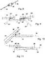
- FIG. 10a further joint of a strut in a first state
- FIG. 11the joint of FIG. 10 in a second state
- FIG. 12a joint of a strut which is provided in a joint section at which two sections are arranged at the end face;
- FIG. 13a film hinge of a strut in a first state
- FIG. 14the film hinge of FIG. 13 in a second state
- FIG. 15a further embodiment of a film hinge
- FIG. 16the embodiment of a joint section at a strut.
- FIG. 1shows a heart pump 1 which is located at its deployment site in the interior of a ventricle 3 and has a rotor 2 which has conveying blades on a hub 10 and is arranged inside a pump housing 9 .
- the pump housing 9is located at the transition from a blood vessel 4 to the ventricle 3 .
- the pumpis able to suck blood out of the ventricle 3 and to convey it into the blood vessel 4 .
- the pump 1is arranged at the end of a hollow catheter 5 which is introduced through a sluice 8 into the body of a patient or into the blood vessel 4 and which accommodates a shaft 6 in its interior which can be driven at high speeds and is connected to the hub 10 within the pump.
- the shaft 6is connected to a motor 7 at its proximal end at the drive side.
- the pump 1To transport the pump 1 through the blood vessel, it can be radially compressed in order then to be radially expanded after being brought into the ventricle 3 and to achieve a correspondingly improved efficiency or the desired pump performance.
- FIG. 2shows by way of example a conveying blade 11 of the rotor 2 in accordance with the invention in which a membrane is spanned between three struts 12 , 13 , 14 and is fastened to the individual struts, for example, by means of adhesive bonding, welding or in a similar manner.
- the membranecan also be attached simply by dipping the struts into a liquid plastic, for example polyurethane.
- the struts 12 , 13 , 14each have a plurality of joints 15 , 16 , 17 of which three or four are respectively shown at the individual struts.
- the struts 12 , 13 , 14converge at their base at a point 37 in which they are fastened to a hub 10 .
- FIG. 3shows a modified construction of a conveying blade 11 ′ with struts 12 ′, 13 ′, 14 ′ which each have joints 15 ′, 16 ′, 17 ′ and which converge at a base 37 ′ which is configured in the form of a segment of an arc of a circle and can be fastened to a correspondingly formed hub 10 of a rotor.
- the movement plane which is aligned within the plane of the struts 12 ′, 13 ′, 14 ′ or tangentially to the membrane at the respective pointis shown by the arrows 38 , 39 in FIG. 3 .
- FIG. 4shows two conveying blades of which the upper one is marked by 11 ′′ and is shown in more detail.
- the two conveying bladesare fastened radially opposite to one another, symmetrically at a hub 10 .
- the conveying blade 11 ′′has struts 12 ′′, 13 ′′ between which a membrane is spanned, with each of the struts as well as a third strut 14 ′′ disposed between them having joints 15 ′′, 16 ′′, 17 ′′ which are kinkable in the plane perpendicular to the surface of the conveying blade 11 ′′ or at the respective struts perpendicular to the membrane surface or to the tangent of the membrane surface.
- the individual conveying blades 11 ′′can be folded onto the hub 10 in the axial direction thereof as is shown in FIG. 5 in the compressed state of the rotor with reference to the struts 12 ′′ and 13 ′′.
- the struts 12 ′′, 13 ′are radially erected in operation by centrifugal forces by rotation of the hub, driven by the shaft 6 shown in FIG. 1 .
- FIG. 6shows a further rotor having two conveying blades of which the upper one is marked by 11 ′′′. It has struts 12 ′′′, 13 ′′′, 14 ′′ which are provided with respective joints 15 ′′′, 16 ′′′, 17 ′′′.
- the jointsare each kinkable in a first movement direction within the plane of the conveying blade, i.e. parallel to the membrane in the region of the respective strut or to a tangential surface of the membrane so that the conveying blades 11 ′′′ can be flipped or folded onto the hub 10 in the peripheral direction.
- the struts 12 ′′′, 13 ′′′lie about the hub 10 , as is shown in more detail in FIG. 7 .
- FIG. 8shows the construction of the joints in a first embodiment in more detail, with a support element 20 being shown in the form of a plate between two sections 18 , 19 of a strut.
- the support element 20has two bearing blocks 21 , 22 which are shown in more detail in a side view in FIG. 9 and in which a respective bearing shaft 21 ′, 22 ′ is journalled.
- the sections 19 , 19are rotatably journalled on the corresponding shafts.
- the section 19is additionally shown by dashed lines in the overelongated position 19 ′ on the right hand side of the support element 20 and the second is supported at this position at the point marked by 43 at the support element 20 , whereby a further angling of the section 19 with respect to the section 18 is prevented.
- the section 19 on the right hand sideis marked by 19 ′′ in the kinked position which is likewise shown by dashed lines.
- the corresponding strutis angled or folded with the sections 18 , 19 in this kinked position so that the rotor adopts a compressed position.
- FIG. 10represents a further embodiment of the invention in which a support element has been omitted, the two sections 41 , 42 partly cover one another in the elongated position in the longitudinal direction, with the section 42 having a pivot lever 43 and a support lever 44 at both sides of the bearing point 23 and with the pivot lever 43 projecting beyond the other section 41 and being able to be angled.
- FIG. 11the arrangement is shown with the two sections 41 , 42 in a maximally elongated position, with the section 42 ′ pivoted with respect to FIG. 10 being shown in the maximally overelongated position.
- the support lever 44is supported against the section 41 in this position. A further overelongation of the strut which has the two sections 41 , 42 is thus prevented.
- FIG. 12a strut having two sections 27 , 28 which are connected to one another by a joint section 29 is shown schematically.
- FIG. 13shows in more specific form a cut-out 30 in the form of a slit or incision which is introduced into the strut between the sections 27 ′, 28 ′.
- FIG. 14shows the strut of FIG. 13 in a kinked arrangement of the sections 27 ′, 28 ′, with the film hinge 31 lying on the inner side of the strut and the cut-out 30 on its outer side.
- the sections 27 ′, 28 ′thus include a smaller angle on the inner side than on the outer side when the strut is angled.
- the sections on the inner sidehave an angle which amounts to a maximum of 180°, or only a little above it, for example to a maximum of 190°.
- FIG. 15another form of the cut-out 32 is shown which does not follow a straight cut, but rather a more complicated shape and which thus provide a longer and more flexible film hinge.
- Such a complex cut-out 32can be introduced, for example, by means of laser cutting or etching techniques or other erosive processing techniques.
- FIG. 16represents another alternative in the formation of a joint at a strut.
- the joint section between two sections 27 ′′′ and 28 ′′′is marked by 33 .
- This joint section 32has a material 34 on the inner side which can also extend over the center plane 45 of the corresponding strut up to the outer side of the strut which extends perpendicular to the plane of the drawing.
- a layer 35is advantageously provided at the outer side of the strut, said layer being harder than the material 34 and above all being incompressible so that the strut cannot be angled toward the outer side and the overelongation of the strut is already prevented by the property of the material of the part 35 .
- the material 34is advantageously easily compressible, but solid.
- a layer 36is shown in FIG. 16 which can likewise be attached to the outer side of the strut instead of the layer 35 , or additionally thereto, but is stretchable just like the material of the layer 35 so that, on the one hand, a kinking of the sections 27 ′′′, 28 ′′′ toward the inner side of the strut is allowed, a kinking of the sections toward the outer side is, however, limited.
- a simple compressibility of a rotor for a fluid pumpis achieved by the design in accordance with the invention of conveying blades or of a rotor for a fluid pump having the corresponding joints so that the conveying blades can be brought into the compressed state completely without counter-forces or with small elastic counter-forces and can also be erected again after being brought to the operating site.
- the described jointsare of simple design, are simple to manufacture and are reliable and give the corresponding conveying blades a high flexibility.
Landscapes
- Health & Medical Sciences (AREA)
- Engineering & Computer Science (AREA)
- Heart & Thoracic Surgery (AREA)
- Mechanical Engineering (AREA)
- Cardiology (AREA)
- Biomedical Technology (AREA)
- General Health & Medical Sciences (AREA)
- Anesthesiology (AREA)
- Veterinary Medicine (AREA)
- Hematology (AREA)
- Life Sciences & Earth Sciences (AREA)
- Animal Behavior & Ethology (AREA)
- Public Health (AREA)
- General Engineering & Computer Science (AREA)
- Vascular Medicine (AREA)
- Transplantation (AREA)
- External Artificial Organs (AREA)
- Reciprocating Pumps (AREA)
- Structures Of Non-Positive Displacement Pumps (AREA)
Abstract
Description
Claims (20)
Priority Applications (6)
| Application Number | Priority Date | Filing Date | Title |
|---|---|---|---|
| US16/037,758US10806838B2 (en) | 2009-12-23 | 2018-07-17 | Conveying blades for a compressible rotor |
| US17/023,837US11266824B2 (en) | 2009-12-23 | 2020-09-17 | Conveying blades for a compressible rotor |
| US17/590,531US11549517B2 (en) | 2009-12-23 | 2022-02-01 | Conveying blades for a compressible rotor |
| US18/079,995US11773863B2 (en) | 2009-12-23 | 2022-12-13 | Conveying blades for a compressible rotor |
| US18/238,564US12117014B2 (en) | 2009-12-23 | 2023-08-28 | Conveying blades for a compressible rotor |
| US18/885,089US12305662B2 (en) | 2009-12-23 | 2024-09-13 | Conveying blades for a compressible rotor |
Applications Claiming Priority (8)
| Application Number | Priority Date | Filing Date | Title |
|---|---|---|---|
| US28964509P | 2009-12-23 | 2009-12-23 | |
| EP09075571AEP2338540A1 (en) | 2009-12-23 | 2009-12-23 | Delivery blade for a compressible rotor |
| EP09075571.1 | 2009-12-23 | ||
| EP09075571 | 2009-12-23 | ||
| PCT/EP2010/007998WO2011076441A1 (en) | 2009-12-23 | 2010-12-23 | Conveying blades for a compressible rotor |
| US201213261319A | 2012-08-08 | 2012-08-08 | |
| US15/069,627US10052419B2 (en) | 2009-12-23 | 2016-03-14 | Conveying blades for a compressible rotor |
| US16/037,758US10806838B2 (en) | 2009-12-23 | 2018-07-17 | Conveying blades for a compressible rotor |
Related Parent Applications (1)
| Application Number | Title | Priority Date | Filing Date |
|---|---|---|---|
| US15/069,627ContinuationUS10052419B2 (en) | 2009-12-23 | 2016-03-14 | Conveying blades for a compressible rotor |
Related Child Applications (1)
| Application Number | Title | Priority Date | Filing Date |
|---|---|---|---|
| US17/023,837ContinuationUS11266824B2 (en) | 2009-12-23 | 2020-09-17 | Conveying blades for a compressible rotor |
Publications (2)
| Publication Number | Publication Date |
|---|---|
| US20190099532A1 US20190099532A1 (en) | 2019-04-04 |
| US10806838B2true US10806838B2 (en) | 2020-10-20 |
Family
ID=42215607
Family Applications (8)
| Application Number | Title | Priority Date | Filing Date |
|---|---|---|---|
| US13/261,319Active2032-11-22US9314558B2 (en) | 2009-12-23 | 2010-12-23 | Conveying blades for a compressible rotor |
| US15/069,627Active2031-11-20US10052419B2 (en) | 2009-12-23 | 2016-03-14 | Conveying blades for a compressible rotor |
| US16/037,758Active2031-05-27US10806838B2 (en) | 2009-12-23 | 2018-07-17 | Conveying blades for a compressible rotor |
| US17/023,837ActiveUS11266824B2 (en) | 2009-12-23 | 2020-09-17 | Conveying blades for a compressible rotor |
| US17/590,531ActiveUS11549517B2 (en) | 2009-12-23 | 2022-02-01 | Conveying blades for a compressible rotor |
| US18/079,995ActiveUS11773863B2 (en) | 2009-12-23 | 2022-12-13 | Conveying blades for a compressible rotor |
| US18/238,564ActiveUS12117014B2 (en) | 2009-12-23 | 2023-08-28 | Conveying blades for a compressible rotor |
| US18/885,089ActiveUS12305662B2 (en) | 2009-12-23 | 2024-09-13 | Conveying blades for a compressible rotor |
Family Applications Before (2)
| Application Number | Title | Priority Date | Filing Date |
|---|---|---|---|
| US13/261,319Active2032-11-22US9314558B2 (en) | 2009-12-23 | 2010-12-23 | Conveying blades for a compressible rotor |
| US15/069,627Active2031-11-20US10052419B2 (en) | 2009-12-23 | 2016-03-14 | Conveying blades for a compressible rotor |
Family Applications After (5)
| Application Number | Title | Priority Date | Filing Date |
|---|---|---|---|
| US17/023,837ActiveUS11266824B2 (en) | 2009-12-23 | 2020-09-17 | Conveying blades for a compressible rotor |
| US17/590,531ActiveUS11549517B2 (en) | 2009-12-23 | 2022-02-01 | Conveying blades for a compressible rotor |
| US18/079,995ActiveUS11773863B2 (en) | 2009-12-23 | 2022-12-13 | Conveying blades for a compressible rotor |
| US18/238,564ActiveUS12117014B2 (en) | 2009-12-23 | 2023-08-28 | Conveying blades for a compressible rotor |
| US18/885,089ActiveUS12305662B2 (en) | 2009-12-23 | 2024-09-13 | Conveying blades for a compressible rotor |
Country Status (5)
| Country | Link |
|---|---|
| US (8) | US9314558B2 (en) |
| EP (1) | EP2338540A1 (en) |
| CN (1) | CN102665786B (en) |
| DE (1) | DE112010004979T5 (en) |
| WO (1) | WO2011076441A1 (en) |
Cited By (12)
| Publication number | Priority date | Publication date | Assignee | Title |
|---|---|---|---|---|
| US11648387B2 (en) | 2015-05-18 | 2023-05-16 | Magenta Medical Ltd. | Blood pump |
| US11648391B2 (en) | 2013-03-13 | 2023-05-16 | Magenta Medical Ltd. | Blood pump |
| US11648392B2 (en) | 2016-11-23 | 2023-05-16 | Magenta Medical Ltd. | Blood pumps |
| US11666747B2 (en) | 2019-01-24 | 2023-06-06 | Magenta Medical Ltd. | Manufacturing an impeller |
| US11684275B2 (en) | 2018-01-10 | 2023-06-27 | Magenta Medical Ltd. | Distal tip element for blood pump |
| US11839754B2 (en) | 2016-10-25 | 2023-12-12 | Magenta Medical Ltd | Ventricular assist device |
| US11839540B2 (en) | 2012-06-06 | 2023-12-12 | Magenta Medical Ltd | Vena-caval apparatus and methods |
| US11883274B2 (en) | 2013-03-13 | 2024-01-30 | Magenta Medical Ltd. | Vena-caval blood pump |
| US12128227B2 (en) | 2020-04-07 | 2024-10-29 | Magenta Medical Ltd. | Manufacture of an impeller |
| US12128228B2 (en) | 2019-05-23 | 2024-10-29 | Magenta Medical Ltd | Blood pumps |
| US12343518B2 (en) | 2018-01-10 | 2025-07-01 | Magenta Medical Ltd. | Blood-pressure-measurement element |
| US12440665B2 (en) | 2021-11-22 | 2025-10-14 | Magenta Medical Ltd. | Magnetic phase detection |
Families Citing this family (91)
| Publication number | Priority date | Publication date | Assignee | Title |
|---|---|---|---|---|
| US7393181B2 (en) | 2004-09-17 | 2008-07-01 | The Penn State Research Foundation | Expandable impeller pump |
| CN102380135A (en) | 2006-03-23 | 2012-03-21 | 宾州研究基金会 | Heart assist device with expandable impeller pump |
| EP2194278A1 (en) | 2008-12-05 | 2010-06-09 | ECP Entwicklungsgesellschaft mbH | Fluid pump with a rotor |
| EP2216059A1 (en) | 2009-02-04 | 2010-08-11 | ECP Entwicklungsgesellschaft mbH | Catheter device with a catheter and an actuation device |
| EP2229965A1 (en) | 2009-03-18 | 2010-09-22 | ECP Entwicklungsgesellschaft mbH | Fluid pump with particular form of a rotor blade |
| EP2246078A1 (en) | 2009-04-29 | 2010-11-03 | ECP Entwicklungsgesellschaft mbH | Shaft assembly with a shaft which moves within a fluid-filled casing |
| EP2248544A1 (en) | 2009-05-05 | 2010-11-10 | ECP Entwicklungsgesellschaft mbH | Fluid pump with variable circumference, particularly for medical use |
| EP2266640A1 (en) | 2009-06-25 | 2010-12-29 | ECP Entwicklungsgesellschaft mbH | Compressible and expandable turbine blade for a fluid pump |
| EP2282070B1 (en) | 2009-08-06 | 2012-10-17 | ECP Entwicklungsgesellschaft mbH | Catheter device with a coupling device for a drive device |
| EP2299119B1 (en) | 2009-09-22 | 2018-11-07 | ECP Entwicklungsgesellschaft mbH | Inflatable rotor for a fluid pump |
| EP2298371A1 (en) | 2009-09-22 | 2011-03-23 | ECP Entwicklungsgesellschaft mbH | Function element, in particular fluid pump with a housing and a transport element |
| EP2298373A1 (en) | 2009-09-22 | 2011-03-23 | ECP Entwicklungsgesellschaft mbH | Fluid pump with at least one turbine blade and a seating device |
| EP2298372A1 (en) | 2009-09-22 | 2011-03-23 | ECP Entwicklungsgesellschaft mbH | Rotor for an axial pump for transporting a fluid |
| EP2314330A1 (en) | 2009-10-23 | 2011-04-27 | ECP Entwicklungsgesellschaft mbH | Flexible shaft arrangement |
| EP2314331B1 (en) | 2009-10-23 | 2013-12-11 | ECP Entwicklungsgesellschaft mbH | Catheter pump arrangement and flexible shaft arrangement with a cable core |
| EP2338540A1 (en) | 2009-12-23 | 2011-06-29 | ECP Entwicklungsgesellschaft mbH | Delivery blade for a compressible rotor |
| EP2338541A1 (en) | 2009-12-23 | 2011-06-29 | ECP Entwicklungsgesellschaft mbH | Radial compressible and expandable rotor for a fluid pump |
| EP2338539A1 (en) | 2009-12-23 | 2011-06-29 | ECP Entwicklungsgesellschaft mbH | Pump device with a detection device |
| EP2347778A1 (en) | 2010-01-25 | 2011-07-27 | ECP Entwicklungsgesellschaft mbH | Fluid pump with a radially compressible rotor |
| EP2363157A1 (en) | 2010-03-05 | 2011-09-07 | ECP Entwicklungsgesellschaft mbH | Device for exerting mechanical force on a medium, in particular fluid pump |
| EP2388029A1 (en) | 2010-05-17 | 2011-11-23 | ECP Entwicklungsgesellschaft mbH | Pump array |
| EP2399639A1 (en) | 2010-06-25 | 2011-12-28 | ECP Entwicklungsgesellschaft mbH | System for introducing a pump |
| EP2407185A1 (en)* | 2010-07-15 | 2012-01-18 | ECP Entwicklungsgesellschaft mbH | Radial compressible and expandable rotor for a pump with a turbine blade |
| EP2407186A1 (en) | 2010-07-15 | 2012-01-18 | ECP Entwicklungsgesellschaft mbH | Rotor for a pump, produced with an initial elastic material |
| EP2407187A3 (en) | 2010-07-15 | 2012-06-20 | ECP Entwicklungsgesellschaft mbH | Blood pump for invasive application within the body of a patient |
| EP2422735A1 (en) | 2010-08-27 | 2012-02-29 | ECP Entwicklungsgesellschaft mbH | Implantable blood transportation device, manipulation device and coupling device |
| WO2012094641A2 (en) | 2011-01-06 | 2012-07-12 | Thoratec Corporation | Percutaneous heart pump |
| EP2497521A1 (en) | 2011-03-10 | 2012-09-12 | ECP Entwicklungsgesellschaft mbH | Push device for axial insertion of a string-shaped, flexible body |
| EP2564771A1 (en) | 2011-09-05 | 2013-03-06 | ECP Entwicklungsgesellschaft mbH | Medicinal product with a functional element for invasive use in the body of a patient |
| US8926492B2 (en) | 2011-10-11 | 2015-01-06 | Ecp Entwicklungsgesellschaft Mbh | Housing for a functional element |
| EP4218887A1 (en) | 2012-05-14 | 2023-08-02 | Tc1 Llc | Mechanical circulatory support device for stabilizing a patient after cardiogenic shock |
| US8721517B2 (en) | 2012-05-14 | 2014-05-13 | Thoratec Corporation | Impeller for catheter pump |
| US9446179B2 (en) | 2012-05-14 | 2016-09-20 | Thoratec Corporation | Distal bearing support |
| US9872947B2 (en) | 2012-05-14 | 2018-01-23 | Tc1 Llc | Sheath system for catheter pump |
| EP4186557A1 (en) | 2012-07-03 | 2023-05-31 | Tc1 Llc | Motor assembly for catheter pump |
| US9421311B2 (en) | 2012-07-03 | 2016-08-23 | Thoratec Corporation | Motor assembly for catheter pump |
| US9358329B2 (en) | 2012-07-03 | 2016-06-07 | Thoratec Corporation | Catheter pump |
| US11077294B2 (en) | 2013-03-13 | 2021-08-03 | Tc1 Llc | Sheath assembly for catheter pump |
| WO2014164136A1 (en) | 2013-03-13 | 2014-10-09 | Thoratec Corporation | Fluid handling system |
| US11033728B2 (en) | 2013-03-13 | 2021-06-15 | Tc1 Llc | Fluid handling system |
| US9308302B2 (en) | 2013-03-15 | 2016-04-12 | Thoratec Corporation | Catheter pump assembly including a stator |
| EP4190376A1 (en) | 2013-03-15 | 2023-06-07 | Tc1 Llc | Catheter pump assembly including a stator |
| EP2860849B1 (en) | 2013-10-11 | 2016-09-14 | ECP Entwicklungsgesellschaft mbH | Compressible motor, implanting assembly and method for positioning the motor |
| US9764113B2 (en) | 2013-12-11 | 2017-09-19 | Magenta Medical Ltd | Curved catheter |
| GB2527075A (en)* | 2014-03-17 | 2015-12-16 | Daassist As | Percutaneous system, devices and methods |
| WO2015160943A1 (en) | 2014-04-15 | 2015-10-22 | Thoratec Corporation | Sensors for catheter pumps |
| EP3131597B1 (en) | 2014-04-15 | 2020-12-02 | Tc1 Llc | Catheter pump introducer systems |
| US10583232B2 (en) | 2014-04-15 | 2020-03-10 | Tc1 Llc | Catheter pump with off-set motor position |
| EP3131599B1 (en) | 2014-04-15 | 2019-02-20 | Tc1 Llc | Catheter pump with access ports |
| EP3583973A1 (en) | 2014-08-18 | 2019-12-25 | Tc1 Llc | Guide features for percutaneous catheter pump |
| US9770543B2 (en) | 2015-01-22 | 2017-09-26 | Tc1 Llc | Reduced rotational mass motor assembly for catheter pump |
| WO2016118781A2 (en) | 2015-01-22 | 2016-07-28 | Thoratec Corporation | Motor assembly with heat exchanger for catheter pump |
| US9675738B2 (en) | 2015-01-22 | 2017-06-13 | Tc1 Llc | Attachment mechanisms for motor of catheter pump |
| US10893847B2 (en) | 2015-12-30 | 2021-01-19 | Nuheart As | Transcatheter insertion system |
| US11160970B2 (en) | 2016-07-21 | 2021-11-02 | Tc1 Llc | Fluid seals for catheter pump motor assembly |
| EP3808401A1 (en) | 2016-07-21 | 2021-04-21 | Tc1 Llc | Gas-filled chamber for catheter pump motor assembly |
| EP3518825B1 (en) | 2016-09-29 | 2020-05-27 | Magenta Medical Ltd. | Blood vessel tube |
| US10537672B2 (en) | 2016-10-07 | 2020-01-21 | Nuheart As | Transcatheter device and system for the delivery of intracorporeal devices |
| US10335528B2 (en) | 2016-10-07 | 2019-07-02 | Nuheart As | Transcatheter method and system for the delivery of intracorporeal devices |
| US10537670B2 (en) | 2017-04-28 | 2020-01-21 | Nuheart As | Ventricular assist device and method |
| US10888646B2 (en) | 2017-04-28 | 2021-01-12 | Nuheart As | Ventricular assist device and method |
| CA3066361A1 (en) | 2017-06-07 | 2018-12-13 | Shifamed Holdings, Llc | Intravascular fluid movement devices, systems, and methods of use |
| WO2019094963A1 (en) | 2017-11-13 | 2019-05-16 | Shifamed Holdings, Llc | Intravascular fluid movement devices, systems, and methods of use |
| DE102018201030B4 (en) | 2018-01-24 | 2025-10-16 | Kardion Gmbh | Magnetic dome element with magnetic bearing function |
| CN112004563B (en) | 2018-02-01 | 2024-08-06 | 施菲姆德控股有限责任公司 | Intravascular blood pump and methods of use and manufacture |
| AU2019230022C1 (en) | 2018-03-06 | 2025-05-01 | Indiana University Research And Technology Corporation | Blood pressure powered auxiliary pump |
| US10893927B2 (en) | 2018-03-29 | 2021-01-19 | Magenta Medical Ltd. | Inferior vena cava blood-flow implant |
| DE102018207575A1 (en) | 2018-05-16 | 2019-11-21 | Kardion Gmbh | Magnetic face turning coupling for the transmission of torques |
| DE102018207611A1 (en) | 2018-05-16 | 2019-11-21 | Kardion Gmbh | Rotor bearing system |
| DE102018208539A1 (en) | 2018-05-30 | 2019-12-05 | Kardion Gmbh | A motor housing module for sealing an engine compartment of a motor of a cardiac assist system and cardiac assistance system and method for mounting a cardiac assist system |
| DE102018208538A1 (en) | 2018-05-30 | 2019-12-05 | Kardion Gmbh | Intravascular blood pump and process for the production of electrical conductors |
| DE102018208541A1 (en) | 2018-05-30 | 2019-12-05 | Kardion Gmbh | Axial pump for a cardiac assist system and method of making an axial pump for a cardiac assist system |
| DE102018208550A1 (en) | 2018-05-30 | 2019-12-05 | Kardion Gmbh | A lead device for directing blood flow to a cardiac assist system, cardiac assist system, and method of making a lead device |
| DE102018210076A1 (en) | 2018-06-21 | 2019-12-24 | Kardion Gmbh | Method and device for detecting a state of wear of a cardiac support system, method and device for operating a cardiac support system and cardiac support system |
| DE102018210058A1 (en) | 2018-06-21 | 2019-12-24 | Kardion Gmbh | Stator blade device for guiding the flow of a fluid flowing out of an outlet opening of a heart support system, heart support system with stator blade device, method for operating a stator blade device and manufacturing method |
| DE102018211327A1 (en) | 2018-07-10 | 2020-01-16 | Kardion Gmbh | Impeller for an implantable vascular support system |
| DE102018212153A1 (en) | 2018-07-20 | 2020-01-23 | Kardion Gmbh | Inlet line for a pump unit of a cardiac support system, cardiac support system and method for producing an inlet line for a pump unit of a cardiac support system |
| US11541224B2 (en) | 2018-07-30 | 2023-01-03 | Cardiovascular Systems, Inc. | Intravascular pump without inducer and centrifugal force-driven expansion of impeller blades and/or expandable and collapsible impeller housing |
| US12161857B2 (en) | 2018-07-31 | 2024-12-10 | Shifamed Holdings, Llc | Intravascular blood pumps and methods of use |
| CN112654389A (en) | 2018-08-07 | 2021-04-13 | 开迪恩有限公司 | Bearing device for a cardiac support system and method for flushing an intermediate space in a bearing device for a cardiac support system |
| WO2020073047A1 (en) | 2018-10-05 | 2020-04-09 | Shifamed Holdings, Llc | Intravascular blood pumps and methods of use |
| US12097016B2 (en) | 2019-03-14 | 2024-09-24 | Abiomed, Inc. | Blood flow rate measurement system |
| WO2021011473A1 (en) | 2019-07-12 | 2021-01-21 | Shifamed Holdings, Llc | Intravascular blood pumps and methods of manufacture and use |
| US11654275B2 (en) | 2019-07-22 | 2023-05-23 | Shifamed Holdings, Llc | Intravascular blood pumps with struts and methods of use and manufacture |
| US12121713B2 (en) | 2019-09-25 | 2024-10-22 | Shifamed Holdings, Llc | Catheter blood pumps and collapsible blood conduits |
| EP4501393A3 (en) | 2019-09-25 | 2025-04-09 | Shifamed Holdings, LLC | Catheter blood pumps and collapsible pump housings |
| WO2021062265A1 (en) | 2019-09-25 | 2021-04-01 | Shifamed Holdings, Llc | Intravascular blood pump systems and methods of use and control thereof |
| EP4072650A4 (en) | 2019-12-11 | 2024-01-10 | Shifamed Holdings, LLC | Descending aorta and vena cava blood pumps |
| DE102020102474A1 (en) | 2020-01-31 | 2021-08-05 | Kardion Gmbh | Pump for conveying a fluid and method for manufacturing a pump |
| US11969586B2 (en) | 2021-03-02 | 2024-04-30 | Heartware, Inc. | Blood pump impeller |
| CN115591109A (en)* | 2022-08-01 | 2023-01-13 | 利为惠德无锡医疗科技有限公司(Cn) | A deformable rear guide vane structure and artificial heart |
Citations (186)
| Publication number | Priority date | Publication date | Assignee | Title |
|---|---|---|---|---|
| US3510229A (en) | 1968-07-23 | 1970-05-05 | Maytag Co | One-way pump |
| US3568659A (en) | 1968-09-24 | 1971-03-09 | James N Karnegis | Disposable percutaneous intracardiac pump and method of pumping blood |
| DE2207296A1 (en) | 1971-02-17 | 1972-08-31 | Somers, S. Brice L., Genf (Schweiz) | Flexible device for conveying granular powdery or liquid goods |
| DE2113986A1 (en) | 1971-03-23 | 1972-09-28 | Svu Textilni | Artificial heart machine - with ptfe or similar inert plastic coated parts,as intracorperal replacement |
| DE2233293A1 (en) | 1971-07-06 | 1973-01-25 | Vni I Ispytatelnyj I Med Techn | DEVICE TO FACILITATE HEARTINESS |
| US3812812A (en) | 1973-06-25 | 1974-05-28 | M Hurwitz | Trolling propeller with self adjusting hydrodynamic spoilers |
| US4014317A (en) | 1972-02-18 | 1977-03-29 | The United States Of America As Represented By The Department Of Health, Education And Welfare | Multipurpose cardiocirculatory assist cannula and methods of use thereof |
| US4207028A (en) | 1979-06-12 | 1980-06-10 | Ridder Sven O | Extendable and retractable propeller for watercraft |
| US4559951A (en) | 1982-11-29 | 1985-12-24 | Cardiac Pacemakers, Inc. | Catheter assembly |
| US4563181A (en) | 1983-02-18 | 1986-01-07 | Mallinckrodt, Inc. | Fused flexible tip catheter |
| US4679558A (en) | 1985-08-12 | 1987-07-14 | Intravascular Surgical Instruments, Inc. | Catheter based surgical methods and apparatus therefor |
| US4686982A (en) | 1985-06-19 | 1987-08-18 | John Nash | Spiral wire bearing for rotating wire drive catheter |
| US4747821A (en) | 1986-10-22 | 1988-05-31 | Intravascular Surgical Instruments, Inc. | Catheter with high speed moving working head |
| US4749376A (en) | 1986-10-24 | 1988-06-07 | Intravascular Surgical Instruments, Inc. | Reciprocating working head catheter |
| US4753221A (en) | 1986-10-22 | 1988-06-28 | Intravascular Surgical Instruments, Inc. | Blood pumping catheter and method of use |
| US4801243A (en) | 1985-12-28 | 1989-01-31 | Bird-Johnson Company | Adjustable diameter screw propeller |
| US4817613A (en) | 1987-07-13 | 1989-04-04 | Devices For Vascular Intervention, Inc. | Guiding catheter |
| US4919647A (en) | 1988-10-13 | 1990-04-24 | Kensey Nash Corporation | Aortically located blood pumping catheter and method of use |
| US4957504A (en) | 1988-12-02 | 1990-09-18 | Chardack William M | Implantable blood pump |
| US4969865A (en) | 1989-01-09 | 1990-11-13 | American Biomed, Inc. | Helifoil pump |
| US4995857A (en) | 1989-04-07 | 1991-02-26 | Arnold John R | Left ventricular assist device and method for temporary and permanent procedures |
| US5011469A (en) | 1988-08-29 | 1991-04-30 | Shiley, Inc. | Peripheral cardiopulmonary bypass and coronary reperfusion system |
| GB2239675A (en) | 1989-12-05 | 1991-07-10 | Man Fai Shiu | Pump for pumping liquid |
| US5040944A (en) | 1989-09-11 | 1991-08-20 | Cook Einar P | Pump having impeller rotational about convoluted stationary member |
| US5042984A (en) | 1989-08-17 | 1991-08-27 | Kensey Nash Corporation | Catheter with working head having selectable impacting surfaces and method of using the same |
| US5052404A (en) | 1989-03-02 | 1991-10-01 | The Microspring Company, Inc. | Torque transmitter |
| US5061256A (en) | 1987-12-07 | 1991-10-29 | Johnson & Johnson | Inflow cannula for intravascular blood pumps |
| DE4124299A1 (en) | 1990-07-20 | 1992-01-23 | Aymerich Diego Figuera | INTRAVENTRICULAR EXPANDABLE AUXILIARY PUMP |
| WO1992002263A1 (en) | 1989-02-23 | 1992-02-20 | Nimbus Medical, Inc. | Percutaneous axial flow bloodpump |
| US5092844A (en) | 1990-04-10 | 1992-03-03 | Mayo Foundation For Medical Education And Research | Intracatheter perfusion pump apparatus and method |
| US5097849A (en) | 1989-08-17 | 1992-03-24 | Kensey Nash Corporation | Method of use of catheter with working head having selectable impacting surfaces |
| US5108411A (en) | 1990-03-28 | 1992-04-28 | Cardiovascular Imaging Systems, Inc. | Flexible catheter drive cable |
| US5112292A (en) | 1989-01-09 | 1992-05-12 | American Biomed, Inc. | Helifoil pump |
| US5113872A (en) | 1990-04-18 | 1992-05-19 | Cordis Corporation | Guidewire extension system with connectors |
| US5118264A (en) | 1990-01-11 | 1992-06-02 | The Cleveland Clinic Foundation | Purge flow control in rotary blood pumps |
| US5117838A (en) | 1990-04-18 | 1992-06-02 | Cordis Corporation | Rotating guidewire extension system |
| US5145333A (en) | 1990-03-01 | 1992-09-08 | The Cleveland Clinic Foundation | Fluid motor driven blood pump |
| US5151721A (en) | 1990-05-15 | 1992-09-29 | Corning Incorporated | Compression joint for eyeglasses |
| US5163910A (en) | 1990-04-10 | 1992-11-17 | Mayo Foundation For Medical Education And Research | Intracatheter perfusion pump apparatus and method |
| US5183384A (en) | 1988-05-16 | 1993-02-02 | Trumbly Joe H | Foldable propeller assembly |
| WO1993002732A1 (en) | 1991-07-26 | 1993-02-18 | The Regents Of The University Of California | Method and device for retrieving materials from body lumens |
| WO1993003786A1 (en) | 1991-08-26 | 1993-03-04 | Target Therapeutics, Inc. | Extendable guidewire assembly |
| US5191888A (en) | 1990-04-18 | 1993-03-09 | Cordis Corporation | Assembly of an extension guidewire and an alignment tool for same |
| US5201679A (en) | 1991-12-13 | 1993-04-13 | Attwood Corporation | Marine propeller with breakaway hub |
| WO1993014805A1 (en) | 1992-01-28 | 1993-08-05 | Baxter International, Inc. | Guidewire extension system |
| EP0560000A2 (en) | 1991-11-05 | 1993-09-15 | Roberto Parravicini | Ventricular pumping device |
| US5275580A (en) | 1990-03-08 | 1994-01-04 | Kenji Yamazaki | Auxiliary artificial heart of the embedded-in-body type |
| WO1994001148A1 (en) | 1992-07-14 | 1994-01-20 | Aai Corporation | Articulated heart pump and method of use |
| WO1994005347A1 (en) | 1992-09-02 | 1994-03-17 | Reitan Oeyvind | Catheter pump |
| WO1994009835A1 (en) | 1992-10-30 | 1994-05-11 | Robert Jarvik | Cannula pumps for temporary cardiac support |
| WO1994020165A2 (en) | 1993-03-12 | 1994-09-15 | C.R. Bard, Inc. | Anatomically matched steerable ptca guidewire |
| US5373619A (en) | 1987-09-30 | 1994-12-20 | Lake Region Manufacturing Co., Inc. | Method of making a hollow lumen cable |
| EP0629412A2 (en) | 1993-06-03 | 1994-12-21 | Sun Medical Technology Research Corporation | Auxiliary artificial heart embedded in a ventricle of a heart |
| WO1995023000A2 (en) | 1994-02-25 | 1995-08-31 | General Dynamics Corporation | Reciprocating pump arrangement |
| US5501574A (en) | 1993-06-28 | 1996-03-26 | Baxter International Inc. | Blood pump |
| WO1996018358A1 (en) | 1994-12-16 | 1996-06-20 | Robert Jarvik | High reliability cardiac assist system |
| US5531789A (en) | 1993-12-24 | 1996-07-02 | Sun Medical Technology Research Corporation | Sealing system of an artificial internal organ |
| WO1996025969A2 (en) | 1995-02-21 | 1996-08-29 | C. R. Bard, Inc. | High performance wires for use in medical devices and alloys therefor |
| DE19535781A1 (en) | 1995-09-26 | 1997-03-27 | Fraunhofer Ges Forschung | System for active flow support of body fluids |
| EP0768091A1 (en) | 1995-10-16 | 1997-04-16 | Sun Medical Technology Research Corporation | Artificial heart |
| WO1997044071A1 (en) | 1996-05-21 | 1997-11-27 | Amnon Sudai | Apparatus and methods for revascularization and perfusion |
| US5701911A (en) | 1996-04-05 | 1997-12-30 | Medtronic, Inc. | Guide wire extension docking system |
| DE29804046U1 (en) | 1998-03-07 | 1998-04-30 | Günther, Rolf W., Prof. Dr.med., 52074 Aachen | Percutaneously implantable, self-expanding axial pump for temporary heart support |
| US5813405A (en) | 1990-04-18 | 1998-09-29 | Cordis Corporation | Snap-in connection assembly for extension guidewire system |
| US5820571A (en) | 1996-06-24 | 1998-10-13 | C. R. Bard, Inc. | Medical backloading wire |
| WO1998053864A1 (en) | 1997-05-30 | 1998-12-03 | Cardinove Inc. | Ventricular assist device comprising an enclosed-impeller axial flow blood pump |
| EP0884064A2 (en) | 1997-06-12 | 1998-12-16 | Schneider (Usa) Inc. | Balloon Catheter with impeller for perusing blood |
| US5851174A (en) | 1996-09-17 | 1998-12-22 | Robert Jarvik | Cardiac support device |
| US5877566A (en) | 1996-03-22 | 1999-03-02 | Chen; Chi-Der | Submersible magnetic motor having improved rotary blades |
| US5882329A (en) | 1997-02-12 | 1999-03-16 | Prolifix Medical, Inc. | Apparatus and method for removing stenotic material from stents |
| EP0914171A2 (en) | 1996-06-26 | 1999-05-12 | University Of Pittsburgh | Magnetically suspended miniature fluid pump and method of making the same |
| EP0916359A1 (en) | 1997-11-13 | 1999-05-19 | Impella Cardiotechnik Aktiengesellschaft | Improved cannula device |
| US5938672A (en) | 1996-07-26 | 1999-08-17 | Kensey Nash Corporation | System and method of use for revascularizing stenotic bypass grafts and other blood vessels |
| EP0951302A2 (en) | 1996-10-04 | 1999-10-27 | States Surgical Corporation United | Circulatory support system |
| US6030397A (en) | 1998-12-16 | 2000-02-29 | Micro Therapeutics, Inc. | Miniaturized medical brush |
| WO2000027446A1 (en) | 1998-11-06 | 2000-05-18 | Nagy Adly Habib | Use of implantable pumps |
| EP1019117A1 (en) | 1997-10-02 | 2000-07-19 | Micromed Technology, Inc. | Implantable pump system |
| WO2000043054A2 (en) | 1999-01-26 | 2000-07-27 | Nimbus, Inc. | Blood pump with profiled outflow region |
| WO2000062842A1 (en) | 1999-04-20 | 2000-10-26 | Berlin Heart Ag | Device for the axial transport of fluid media |
| US6152693A (en) | 1993-12-23 | 2000-11-28 | Gori Marine As | Folding propeller |
| CA2311977A1 (en) | 1999-06-18 | 2000-12-18 | Helmut Reul | Method for delivering a fluid into a vessel of a human body, and improved cannula useful for carrying out the method |
| WO2001007760A1 (en) | 1999-07-26 | 2001-02-01 | Impsa International Inc. | Hydraulic seal for rotary pumps |
| WO2001007787A1 (en) | 1999-07-26 | 2001-02-01 | Impsa International Inc. | Continuous flow rotary pump |
| US6254359B1 (en) | 1996-05-10 | 2001-07-03 | The United States Of America As Represented By The Administrator Of The National Aeronautics And Space Administration | Method for providing a jewel bearing for supporting a pump rotor shaft |
| US6302910B1 (en) | 1992-06-23 | 2001-10-16 | Sun Medical Technology Research Corporation | Auxiliary artificial heart of an embedded type |
| US6308632B1 (en) | 1998-11-23 | 2001-10-30 | James E. Shaffer | Deployable folded propeller assembly for aerial projectiles |
| WO2001083016A2 (en) | 2000-05-01 | 2001-11-08 | Flowmedica, Inc. | Apparatus and methods for treating congestive heart disease |
| DE10059714C1 (en) | 2000-12-01 | 2002-05-08 | Impella Cardiotech Ag | Intravasal pump has pump stage fitted with flexible expandible sleeve contricted during insertion through blood vessel |
| US20020094273A1 (en) | 2001-01-16 | 2002-07-18 | Yung-Chung Huang | Blade structure for ceiling fan |
| DE10108810A1 (en) | 2001-02-16 | 2002-08-29 | Berlin Heart Ag | Device for the axial conveyance of liquids |
| US20020123661A1 (en) | 1999-07-29 | 2002-09-05 | Verkerke Gijsbertus Jacob | Catheter pump, catheter and method for supporting organ perfusion |
| US6506025B1 (en) | 1999-06-23 | 2003-01-14 | California Institute Of Technology | Bladeless pump |
| US6517315B2 (en) | 2001-05-29 | 2003-02-11 | Hewlett-Packard Company | Enhanced performance fan with the use of winglets |
| US6527521B2 (en) | 2000-01-26 | 2003-03-04 | Nipro Corporation | Magnetically driven axial-flow pump |
| US6537030B1 (en) | 2000-10-18 | 2003-03-25 | Fasco Industries, Inc. | Single piece impeller having radial output |
| DE10155011A1 (en) | 2001-11-02 | 2003-05-22 | Cardioberlin Gmbh | Intra-aortal pump system for supporting or replacing the heart pumping function is inserted into the heart and aorta using an adjustable guide and support bracket through an incision in the heart apex |
| US6592612B1 (en) | 2000-05-04 | 2003-07-15 | Cardeon Corporation | Method and apparatus for providing heat exchange within a catheter body |
| US20030135086A1 (en) | 2001-11-19 | 2003-07-17 | University Of Medicine And Dentistry Of New Jersey | Temporary blood circulation assist device |
| WO2003057013A2 (en) | 2002-01-08 | 2003-07-17 | Micromed Technology, Inc. | Method and system for detecting ventricular collapse |
| US6652548B2 (en) | 2000-03-31 | 2003-11-25 | Bacchus Vascular Inc. | Expansible shearing catheters for thrombus removal |
| WO2003103745A2 (en) | 2002-06-11 | 2003-12-18 | Walid Aboul-Hosn | Expandable blood pump and related methods |
| US20030231959A1 (en) | 2002-06-12 | 2003-12-18 | William Hackett | Impeller assembly for centrifugal pumps |
| US20040046466A1 (en) | 2000-11-25 | 2004-03-11 | Thorsten Siess | Miniature motor |
| US20040093074A1 (en) | 2000-11-21 | 2004-05-13 | Gesine Hildebrand | Tubular vascular implants (stents) and methods for producing the same |
| RU2229899C2 (en) | 2002-03-20 | 2004-06-10 | Федеральный научно-производственный центр закрытое акционерное общество "Научно-производственный концерн (объединение) "ЭНЕРГИЯ" | Device for supporting assist blood circulation |
| DE10336902B3 (en) | 2003-08-08 | 2004-08-19 | Impella Cardiosystems Ag | Intracardial pumping device has flexible projection on distal side of suction head inlet openings acting as mechanical spacer holding pumping device away from heart chamber walls |
| US6790171B1 (en) | 1999-03-09 | 2004-09-14 | Universitair Medisch Cenrum Utrecht | Method and device for transventricular mechanical circulatory support |
| US20040215228A1 (en) | 2003-04-28 | 2004-10-28 | Cardiac Pacemakers, Inc. | Compliant guiding catheter sheath system |
| US20040215222A1 (en) | 2003-04-25 | 2004-10-28 | Michael Krivoruchko | Intravascular material removal device |
| WO2005002646A1 (en) | 2003-07-01 | 2005-01-13 | Ntu Ventures Private Limited | Pump |
| US6860713B2 (en) | 2002-11-27 | 2005-03-01 | Nidec Corporation | Fan with collapsible blades, redundant fan system, and related method |
| GB2405677A (en) | 2003-09-02 | 2005-03-09 | Hewlett Packard Development Co | Rotor with collapsible fan blade |
| WO2005021078A1 (en) | 2003-09-02 | 2005-03-10 | Intra-Vasc.Nl B.V. | Catheter pump, catheter and fittings therefore and methods of using a catheter pump. |
| WO2005030316A1 (en) | 2003-09-26 | 2005-04-07 | Medtronic, Inc. | Sutureless pump connector |
| WO2005032620A1 (en) | 2003-10-09 | 2005-04-14 | Ventracor Limited | Impeller |
| US20050101200A1 (en) | 2003-09-09 | 2005-05-12 | Chad Townsend | Paddle blade |
| WO2005081681A2 (en) | 2004-02-11 | 2005-09-09 | Fort Wayne Metals Research Products Corporation | Drawn strand filled tubing wire |
| US6945977B2 (en) | 1999-12-06 | 2005-09-20 | Bacchus Vascular, Inc. | Systems and methods for clot disruption and retrieval |
| US20060008349A1 (en) | 2004-05-20 | 2006-01-12 | Kenneth Khaw | Replaceable expandable transmyocardial ventricular assist device |
| WO2006020942A1 (en) | 2004-08-13 | 2006-02-23 | Delgado Reynolds M Iii | Method and apparatus for long-term assisting a left ventricle to pump blood |
| US20060062672A1 (en) | 2004-09-17 | 2006-03-23 | Mcbride Mark W | Expandable impeller pump |
| US7022100B1 (en) | 1999-09-03 | 2006-04-04 | A-Med Systems, Inc. | Guidable intravascular blood pump and related methods |
| WO2006051023A1 (en) | 2004-11-12 | 2006-05-18 | Abiomed Europe Gmbh | Folding, intravascularly inserted blood pump |
| US7074018B2 (en) | 2003-07-10 | 2006-07-11 | Sheldon Chang | Direct drive linear flow blood pump |
| US20060195004A1 (en) | 2005-02-28 | 2006-08-31 | Robert Jarvik | Minimally invasive transvalvular ventricular assist device |
| WO2006133209A1 (en) | 2005-06-06 | 2006-12-14 | The Cleveland Clinic Foundation | Blood pump |
| WO2007003351A1 (en) | 2005-07-01 | 2007-01-11 | Coras Medical | An axial flow pump with a spiral-shaped vane |
| US7179273B1 (en) | 1999-06-21 | 2007-02-20 | Endovascular Technologies, Inc. | Filter/emboli extractor for use in variable sized blood vessels |
| WO2007103464A2 (en) | 2006-03-08 | 2007-09-13 | Orqis Medical Corporation | Blood conduit connector |
| WO2007103390A2 (en) | 2006-03-06 | 2007-09-13 | Orqis Medical Corporation | Quick priming connectors for blood circuit |
| WO2007112033A2 (en) | 2006-03-23 | 2007-10-04 | The Penn State Research Foundation | Heart assist device with expandable impeller pump |
| US20070270875A1 (en) | 2006-04-13 | 2007-11-22 | Uwe Bacher | Medical Instrument For Spreading Vertebral Bodies Apart |
| WO2008017289A2 (en) | 2006-08-06 | 2008-02-14 | Mustafa Akdis | Blood pump |
| WO2008034068A2 (en) | 2006-09-14 | 2008-03-20 | Circulite, Inc. | Intravascular blood pump and catheter |
| US20080073983A1 (en) | 2006-09-21 | 2008-03-27 | Dezi Krajcir | Resilient motor mounting system and method of use |
| WO2008054699A2 (en) | 2006-10-30 | 2008-05-08 | Medtronic, Inc | Breakaway connectors and systems |
| US20080132748A1 (en) | 2006-12-01 | 2008-06-05 | Medical Value Partners, Llc | Method for Deployment of a Medical Device |
| US20080132747A1 (en) | 2006-12-01 | 2008-06-05 | Medical Value Partners, Llc | Medical Device |
| WO2008106103A2 (en) | 2007-02-26 | 2008-09-04 | Heartware, Inc. | Intravascular ventricular assist device |
| WO2008116765A2 (en) | 2007-03-24 | 2008-10-02 | Abiomed Europe Gmbh | Blood pump comprising a micromotor |
| WO2008124696A1 (en) | 2007-04-05 | 2008-10-16 | Micromed Technology, Inc. | Blood pump system |
| US20080262584A1 (en) | 2007-03-19 | 2008-10-23 | Bottomley Paul A | Methods and apparatus for fabricating leads with conductors and related flexible lead configurations |
| WO2008137353A1 (en) | 2007-05-01 | 2008-11-13 | Medtronic, Inc. | Offset catheter connector, system and method for use |
| WO2008137352A1 (en) | 2007-05-01 | 2008-11-13 | Medtronic, Inc. | Threaded catheter connector, system, and method |
| US20080306327A1 (en) | 2007-06-05 | 2008-12-11 | Medical Value Partners, Llc | Apparatus Comprising a Drive Cable for a Medical Device |
| WO2009015784A1 (en) | 2007-07-30 | 2009-02-05 | Ifw Manfred Otte Gmbh | Mould-integrated plastifying unit |
| US20090062597A1 (en) | 2007-08-29 | 2009-03-05 | Medical Value Partners, Llc | Article Comprising an Impeller |
| US20090093764A1 (en) | 2007-10-08 | 2009-04-09 | Ais Gmbh Aachen Innovative Solutions | Catheter device |
| US20090093796A1 (en) | 2007-10-08 | 2009-04-09 | Ais Gmbh Aachen Innovative Solutions | Catheter device |
| EP2047872A1 (en) | 2007-10-08 | 2009-04-15 | Ais Gmbh Aachen Innovative Solutions | Catheter device |
| CA2701809A1 (en) | 2007-10-08 | 2009-04-16 | Ais Gmbh Aachen Innovative Solutions | Catheter device |
| WO2009073037A1 (en) | 2007-12-07 | 2009-06-11 | Medical Value Partners, Llc | Medical device |
| EP2218469A1 (en) | 2009-02-12 | 2010-08-18 | ECP Entwicklungsgesellschaft mbH | Casing for a functional element |
| EP2229965A1 (en) | 2009-03-18 | 2010-09-22 | ECP Entwicklungsgesellschaft mbH | Fluid pump with particular form of a rotor blade |
| DE102010011998A1 (en) | 2009-03-24 | 2010-09-30 | Ecp Entwicklungsgesellschaft Mbh | Fluid pumping unit, particularly for medical area for use within body vessel, has fluid pump which consists of pump rotor and drive device for driving fluid pump, where drive device has fluid supply line and drive rotor driven by fluid |
| WO2010133567A1 (en) | 2009-05-18 | 2010-11-25 | Cardiobridge Gmbh | Catheter pump |
| EP2343091A1 (en) | 2010-01-08 | 2011-07-13 | ECP Entwicklungsgesellschaft mbH | Fluid pump with a transport device with controllable volume alteration |
| US20110257462A1 (en) | 2008-10-06 | 2011-10-20 | Indiana University and Technology Corporation | Active or passive assistance in the circulatory system |
| US20110275884A1 (en) | 2008-12-05 | 2011-11-10 | Ecp Entwicklungsgesellschaft Mbh | Fluid pump with a rotor |
| US20120046648A1 (en) | 2009-02-04 | 2012-02-23 | Mario Scheckel | Catheter device having a catheter and an actuation device |
| US20120093628A1 (en) | 2009-05-05 | 2012-04-19 | Ecp Entwicklungsgesellschaft Mbh | Fluid pump changeable in diameter, in particular for medical application |
| US20120101455A1 (en) | 2009-04-29 | 2012-04-26 | Ecp Entwicklungsgesellschaft Mbh | Shaft arrangement having a shaft which extends within a fluid-filled casing |
| US20120142994A1 (en) | 2009-06-25 | 2012-06-07 | Ecp[ Entwicklungsgellschaft Mbh | Compressible and expandable blade for a fluid pump |
| US20120184803A1 (en) | 2009-08-06 | 2012-07-19 | Ecp Entwicklungsgesellschaft Mbh | Catheter device having a coupling device for a drive device |
| US20120224970A1 (en) | 2009-09-22 | 2012-09-06 | Ecp Entwicklungsgesellschaft Mbh | Fluid pump having at least one impeller blade and a support device |
| EP2497521A1 (en) | 2011-03-10 | 2012-09-12 | ECP Entwicklungsgesellschaft mbH | Push device for axial insertion of a string-shaped, flexible body |
| US20120237353A1 (en) | 2009-09-22 | 2012-09-20 | Ecp Entwicklungsgesellschaft Mbh | Compressible rotor for a fluid pump |
| US20120237357A1 (en) | 2009-09-22 | 2012-09-20 | Ecp Entwicklungsgesellschaft Mbh | Rotor for an axial flow pump for conveying a fluid |
| US20120234411A1 (en) | 2009-09-22 | 2012-09-20 | Mario Scheckel | Functional element, in particular fluid pump, having a housing and a conveying element |
| US20120264523A1 (en) | 2009-10-23 | 2012-10-18 | Ecp Entwicklungsgesellschaft Mbh | Flexible shaft arrangement |
| US20120265002A1 (en) | 2009-10-23 | 2012-10-18 | Ecp Entwicklungsgesellschaft Mbh | Catheter pump arrangement and flexible shaft arrangement having a core |
| US20120294727A1 (en) | 2009-12-23 | 2012-11-22 | Ecp Entwicklungsegesellschaft Mbh | Radially compressible and expandable rotor for a fluid pump |
| US20120301318A1 (en) | 2009-12-23 | 2012-11-29 | Sami Er | Conveying blades for a compressible rotor |
| US20120308406A1 (en) | 2009-12-23 | 2012-12-06 | Ecp Entwicklungsgesellschaft Mbh | Pump device having a detection device |
| US20130019968A1 (en) | 2010-01-27 | 2013-01-24 | Ecp Entwicklungsegesellschaft Mbh | Conveying device for a fluid |
| US20130041202A1 (en) | 2010-01-25 | 2013-02-14 | Ecp Entwicklungsgesellschaft Mbh | Fluid pump having a radially compressible rotor |
| US20130060077A1 (en) | 2010-05-17 | 2013-03-07 | Ecp Entwicklungsgesellschaft Mbh | Pump arrangement |
| WO2013034547A1 (en) | 2011-09-05 | 2013-03-14 | Ecp Entwicklungsgesellschaft Mbh | Medical product comprising a functional element for the invasive use in a patient's body |
| US20130066139A1 (en) | 2010-03-05 | 2013-03-14 | Ecp Entwicklungsgesellschaft Mbh | Pump or rotary cutter for operation in a fluid |
| US20130085318A1 (en) | 2010-06-25 | 2013-04-04 | Ecp Entwicklungsgesellschaft Mbh | System for introducing a pump |
| EP2607712A1 (en) | 2011-12-22 | 2013-06-26 | ECP Entwicklungsgesellschaft mbH | Pump housing with an interior for holding a pump rotor |
| EP2606920A1 (en) | 2011-12-22 | 2013-06-26 | ECP Entwicklungsgesellschaft mbH | Sluice device for inserting a catheter |
| EP2606919A1 (en) | 2011-12-22 | 2013-06-26 | ECP Entwicklungsgesellschaft mbH | Sluice device for inserting a catheter |
| US20130177409A1 (en) | 2010-07-15 | 2013-07-11 | Ecp Entwicklungsgesellschaft Mbh | Rotor for a pump, produced with a first elastic material |
| US20130177432A1 (en) | 2010-07-15 | 2013-07-11 | Ecp Entwicklungsgesellschaft Mbh | Radially compressible and expandable rotor for a pump having an impeller blade |
| US20130204362A1 (en) | 2010-07-15 | 2013-08-08 | Ecp Entwicklungsgesellschaft Mbh | Blood pump for the invasive application within a body of a patient |
Family Cites Families (4)
| Publication number | Priority date | Publication date | Assignee | Title |
|---|---|---|---|---|
| US5964694A (en)* | 1997-04-02 | 1999-10-12 | Guidant Corporation | Method and apparatus for cardiac blood flow assistance |
| US5980471A (en) | 1997-10-10 | 1999-11-09 | Advanced Cardiovascular System, Inc. | Guidewire with tubular connector |
| US6217541B1 (en)* | 1999-01-19 | 2001-04-17 | Kriton Medical, Inc. | Blood pump using cross-flow principles |
| CN2754637Y (en)* | 2004-11-26 | 2006-02-01 | 清华大学 | Impeller of heart pump for preventing hemolysis and thrombus |
- 2009
- 2009-12-23EPEP09075571Apatent/EP2338540A1/ennot_activeWithdrawn
- 2010
- 2010-12-23DEDE112010004979Tpatent/DE112010004979T5/enactivePending
- 2010-12-23CNCN201080058800.9Apatent/CN102665786B/enactiveActive
- 2010-12-23WOPCT/EP2010/007998patent/WO2011076441A1/enactiveApplication Filing
- 2010-12-23USUS13/261,319patent/US9314558B2/enactiveActive
- 2016
- 2016-03-14USUS15/069,627patent/US10052419B2/enactiveActive
- 2018
- 2018-07-17USUS16/037,758patent/US10806838B2/enactiveActive
- 2020
- 2020-09-17USUS17/023,837patent/US11266824B2/enactiveActive
- 2022
- 2022-02-01USUS17/590,531patent/US11549517B2/enactiveActive
- 2022-12-13USUS18/079,995patent/US11773863B2/enactiveActive
- 2023
- 2023-08-28USUS18/238,564patent/US12117014B2/enactiveActive
- 2024
- 2024-09-13USUS18/885,089patent/US12305662B2/enactiveActive
Patent Citations (252)
| Publication number | Priority date | Publication date | Assignee | Title |
|---|---|---|---|---|
| US3510229A (en) | 1968-07-23 | 1970-05-05 | Maytag Co | One-way pump |
| US3568659A (en) | 1968-09-24 | 1971-03-09 | James N Karnegis | Disposable percutaneous intracardiac pump and method of pumping blood |
| DE2207296A1 (en) | 1971-02-17 | 1972-08-31 | Somers, S. Brice L., Genf (Schweiz) | Flexible device for conveying granular powdery or liquid goods |
| US3802551A (en) | 1971-02-17 | 1974-04-09 | S Somers | Flexible tubular conveyor |
| DE2113986A1 (en) | 1971-03-23 | 1972-09-28 | Svu Textilni | Artificial heart machine - with ptfe or similar inert plastic coated parts,as intracorperal replacement |
| CA1008330A (en) | 1971-07-06 | 1977-04-12 | Arseny N. Medelyanovsky | Device for facilitating cardiac action |
| DE2233293A1 (en) | 1971-07-06 | 1973-01-25 | Vni I Ispytatelnyj I Med Techn | DEVICE TO FACILITATE HEARTINESS |
| DE2613696A1 (en) | 1972-02-18 | 1977-10-13 | Anthony Matthew Dr Bruno | HEART CIRCULATION SUPPORT DEVICE |
| US4014317A (en) | 1972-02-18 | 1977-03-29 | The United States Of America As Represented By The Department Of Health, Education And Welfare | Multipurpose cardiocirculatory assist cannula and methods of use thereof |
| US3812812A (en) | 1973-06-25 | 1974-05-28 | M Hurwitz | Trolling propeller with self adjusting hydrodynamic spoilers |
| US4207028A (en) | 1979-06-12 | 1980-06-10 | Ridder Sven O | Extendable and retractable propeller for watercraft |
| US4559951A (en) | 1982-11-29 | 1985-12-24 | Cardiac Pacemakers, Inc. | Catheter assembly |
| US4563181A (en) | 1983-02-18 | 1986-01-07 | Mallinckrodt, Inc. | Fused flexible tip catheter |
| US4686982A (en) | 1985-06-19 | 1987-08-18 | John Nash | Spiral wire bearing for rotating wire drive catheter |
| US4679558A (en) | 1985-08-12 | 1987-07-14 | Intravascular Surgical Instruments, Inc. | Catheter based surgical methods and apparatus therefor |
| US4801243A (en) | 1985-12-28 | 1989-01-31 | Bird-Johnson Company | Adjustable diameter screw propeller |
| US4753221A (en) | 1986-10-22 | 1988-06-28 | Intravascular Surgical Instruments, Inc. | Blood pumping catheter and method of use |
| US4747821A (en) | 1986-10-22 | 1988-05-31 | Intravascular Surgical Instruments, Inc. | Catheter with high speed moving working head |
| US4749376A (en) | 1986-10-24 | 1988-06-07 | Intravascular Surgical Instruments, Inc. | Reciprocating working head catheter |
| US4817613A (en) | 1987-07-13 | 1989-04-04 | Devices For Vascular Intervention, Inc. | Guiding catheter |
| US5373619A (en) | 1987-09-30 | 1994-12-20 | Lake Region Manufacturing Co., Inc. | Method of making a hollow lumen cable |
| US5061256A (en) | 1987-12-07 | 1991-10-29 | Johnson & Johnson | Inflow cannula for intravascular blood pumps |
| US5183384A (en) | 1988-05-16 | 1993-02-02 | Trumbly Joe H | Foldable propeller assembly |
| US5011469A (en) | 1988-08-29 | 1991-04-30 | Shiley, Inc. | Peripheral cardiopulmonary bypass and coronary reperfusion system |
| US4919647A (en) | 1988-10-13 | 1990-04-24 | Kensey Nash Corporation | Aortically located blood pumping catheter and method of use |
| US4957504A (en) | 1988-12-02 | 1990-09-18 | Chardack William M | Implantable blood pump |
| US4969865A (en) | 1989-01-09 | 1990-11-13 | American Biomed, Inc. | Helifoil pump |
| US5112292A (en) | 1989-01-09 | 1992-05-12 | American Biomed, Inc. | Helifoil pump |
| EP0480102A1 (en) | 1989-01-09 | 1992-04-15 | American Biomed, Inc. | Helifoil pump |
| WO1992002263A1 (en) | 1989-02-23 | 1992-02-20 | Nimbus Medical, Inc. | Percutaneous axial flow bloodpump |
| US5052404A (en) | 1989-03-02 | 1991-10-01 | The Microspring Company, Inc. | Torque transmitter |
| US4995857A (en) | 1989-04-07 | 1991-02-26 | Arnold John R | Left ventricular assist device and method for temporary and permanent procedures |
| DE69017784T2 (en) | 1989-07-24 | 1995-11-16 | Lake Region Mfg Co Inc | Wire rope with continuous lumen. |
| US5042984A (en) | 1989-08-17 | 1991-08-27 | Kensey Nash Corporation | Catheter with working head having selectable impacting surfaces and method of using the same |
| US5097849A (en) | 1989-08-17 | 1992-03-24 | Kensey Nash Corporation | Method of use of catheter with working head having selectable impacting surfaces |
| US5040944A (en) | 1989-09-11 | 1991-08-20 | Cook Einar P | Pump having impeller rotational about convoluted stationary member |
| GB2239675A (en) | 1989-12-05 | 1991-07-10 | Man Fai Shiu | Pump for pumping liquid |
| US5118264A (en) | 1990-01-11 | 1992-06-02 | The Cleveland Clinic Foundation | Purge flow control in rotary blood pumps |
| US5145333A (en) | 1990-03-01 | 1992-09-08 | The Cleveland Clinic Foundation | Fluid motor driven blood pump |
| DE69103295T2 (en) | 1990-03-08 | 1994-12-01 | Sun Med Tech Res Corp | Artificial auxiliary heart implanted in the body. |
| US5275580A (en) | 1990-03-08 | 1994-01-04 | Kenji Yamazaki | Auxiliary artificial heart of the embedded-in-body type |
| US5108411A (en) | 1990-03-28 | 1992-04-28 | Cardiovascular Imaging Systems, Inc. | Flexible catheter drive cable |
| US5092844A (en) | 1990-04-10 | 1992-03-03 | Mayo Foundation For Medical Education And Research | Intracatheter perfusion pump apparatus and method |
| US5163910A (en) | 1990-04-10 | 1992-11-17 | Mayo Foundation For Medical Education And Research | Intracatheter perfusion pump apparatus and method |
| US5813405A (en) | 1990-04-18 | 1998-09-29 | Cordis Corporation | Snap-in connection assembly for extension guidewire system |
| US5191888A (en) | 1990-04-18 | 1993-03-09 | Cordis Corporation | Assembly of an extension guidewire and an alignment tool for same |
| US5113872A (en) | 1990-04-18 | 1992-05-19 | Cordis Corporation | Guidewire extension system with connectors |
| US5117838A (en) | 1990-04-18 | 1992-06-02 | Cordis Corporation | Rotating guidewire extension system |
| US5151721A (en) | 1990-05-15 | 1992-09-29 | Corning Incorporated | Compression joint for eyeglasses |
| US5169378A (en) | 1990-07-20 | 1992-12-08 | Diego Figuera | Intra-ventricular expansible assist pump |
| DE4124299A1 (en) | 1990-07-20 | 1992-01-23 | Aymerich Diego Figuera | INTRAVENTRICULAR EXPANDABLE AUXILIARY PUMP |
| WO1993002732A1 (en) | 1991-07-26 | 1993-02-18 | The Regents Of The University Of California | Method and device for retrieving materials from body lumens |
| WO1993003786A1 (en) | 1991-08-26 | 1993-03-04 | Target Therapeutics, Inc. | Extendable guidewire assembly |
| EP0560000A2 (en) | 1991-11-05 | 1993-09-15 | Roberto Parravicini | Ventricular pumping device |
| US5201679A (en) | 1991-12-13 | 1993-04-13 | Attwood Corporation | Marine propeller with breakaway hub |
| WO1993014805A1 (en) | 1992-01-28 | 1993-08-05 | Baxter International, Inc. | Guidewire extension system |
| US6387125B1 (en) | 1992-06-23 | 2002-05-14 | Sun Medical Technology Research Corporation | Auxiliary artificial heart of an embedded type |
| US6537315B2 (en) | 1992-06-23 | 2003-03-25 | Sun Medical Technology Research Corporation | Auxiliary artificial heart of an embedded type |
| US6302910B1 (en) | 1992-06-23 | 2001-10-16 | Sun Medical Technology Research Corporation | Auxiliary artificial heart of an embedded type |
| US6336939B1 (en) | 1992-06-23 | 2002-01-08 | Sun Medical Technology Research Corporation | Auxiliary artificial heart of an embedded type |
| US6346120B1 (en) | 1992-06-23 | 2002-02-12 | Sun Medical Technology Research Corporation | Auxiliary artificial heart of an embedded type |
| WO1994001148A1 (en) | 1992-07-14 | 1994-01-20 | Aai Corporation | Articulated heart pump and method of use |
| WO1994005347A1 (en) | 1992-09-02 | 1994-03-17 | Reitan Oeyvind | Catheter pump |
| US5749855A (en) | 1992-09-02 | 1998-05-12 | Reitan; Oyvind | Catheter pump |
| US5888241A (en) | 1992-10-30 | 1999-03-30 | Jarvik; Robert | Cannula pumps for temporary cardiac support and methods of their application and use |
| WO1994009835A1 (en) | 1992-10-30 | 1994-05-11 | Robert Jarvik | Cannula pumps for temporary cardiac support |
| US5776190A (en) | 1992-10-30 | 1998-07-07 | Jarvik; Robert | Cannula pumps for temporary cardiac support and methods of their application and use |
| US5755784A (en) | 1992-10-30 | 1998-05-26 | Jarvik; Robert | Cannula pumps for temporary cardiac support and methods of their application and use |
| US5376114A (en) | 1992-10-30 | 1994-12-27 | Jarvik; Robert | Cannula pumps for temporary cardiac support and methods of their application and use |
| WO1994020165A2 (en) | 1993-03-12 | 1994-09-15 | C.R. Bard, Inc. | Anatomically matched steerable ptca guidewire |
| EP0629412A2 (en) | 1993-06-03 | 1994-12-21 | Sun Medical Technology Research Corporation | Auxiliary artificial heart embedded in a ventricle of a heart |
| DE69407869T2 (en) | 1993-06-03 | 1998-04-30 | Seiko Epson Corp | Artificial auxiliary heart implanted in a cardiac ventricle |
| US5501574A (en) | 1993-06-28 | 1996-03-26 | Baxter International Inc. | Blood pump |
| DE69431204T2 (en) | 1993-06-28 | 2003-08-07 | Jostra Bentley, Inc. | BLOOD PUMP |
| US6152693A (en) | 1993-12-23 | 2000-11-28 | Gori Marine As | Folding propeller |
| DE69427390T2 (en) | 1993-12-24 | 2001-09-20 | Sun Medical Technology Research Corp., Suwa | Sealing system for an artificial internal organ |
| US5531789A (en) | 1993-12-24 | 1996-07-02 | Sun Medical Technology Research Corporation | Sealing system of an artificial internal organ |
| WO1995023000A2 (en) | 1994-02-25 | 1995-08-31 | General Dynamics Corporation | Reciprocating pump arrangement |
| WO1996018358A1 (en) | 1994-12-16 | 1996-06-20 | Robert Jarvik | High reliability cardiac assist system |
| WO1996025969A2 (en) | 1995-02-21 | 1996-08-29 | C. R. Bard, Inc. | High performance wires for use in medical devices and alloys therefor |
| DE19535781A1 (en) | 1995-09-26 | 1997-03-27 | Fraunhofer Ges Forschung | System for active flow support of body fluids |
| DE19711935A1 (en) | 1995-09-26 | 1998-04-02 | Fraunhofer Ges Forschung | Microsurgical apparatus for opening up occluded blood vessel |
| US6508787B2 (en) | 1995-09-26 | 2003-01-21 | Fraunhofer-Gesellschaft Zur Foerderung Der Angewandten Forschung E.V. | System for actively supporting the flow of body fluids |
| EP0768091A1 (en) | 1995-10-16 | 1997-04-16 | Sun Medical Technology Research Corporation | Artificial heart |
| US5877566A (en) | 1996-03-22 | 1999-03-02 | Chen; Chi-Der | Submersible magnetic motor having improved rotary blades |
| US5701911A (en) | 1996-04-05 | 1997-12-30 | Medtronic, Inc. | Guide wire extension docking system |
| US6254359B1 (en) | 1996-05-10 | 2001-07-03 | The United States Of America As Represented By The Administrator Of The National Aeronautics And Space Administration | Method for providing a jewel bearing for supporting a pump rotor shaft |
| WO1997044071A1 (en) | 1996-05-21 | 1997-11-27 | Amnon Sudai | Apparatus and methods for revascularization and perfusion |
| US6168624B1 (en) | 1996-05-21 | 2001-01-02 | Amnon Sudai | Apparatus and methods for revascularization and perfusion |
| US5820571A (en) | 1996-06-24 | 1998-10-13 | C. R. Bard, Inc. | Medical backloading wire |
| EP0914171A2 (en) | 1996-06-26 | 1999-05-12 | University Of Pittsburgh | Magnetically suspended miniature fluid pump and method of making the same |
| EP1114648A2 (en) | 1996-06-26 | 2001-07-11 | University Of Pittsburgh | Fluid pump |
| US5938672A (en) | 1996-07-26 | 1999-08-17 | Kensey Nash Corporation | System and method of use for revascularizing stenotic bypass grafts and other blood vessels |
| US5851174A (en) | 1996-09-17 | 1998-12-22 | Robert Jarvik | Cardiac support device |
| EP0951302A2 (en) | 1996-10-04 | 1999-10-27 | States Surgical Corporation United | Circulatory support system |
| US5882329A (en) | 1997-02-12 | 1999-03-16 | Prolifix Medical, Inc. | Apparatus and method for removing stenotic material from stents |
| WO1998053864A1 (en) | 1997-05-30 | 1998-12-03 | Cardinove Inc. | Ventricular assist device comprising an enclosed-impeller axial flow blood pump |
| US6503224B1 (en) | 1997-06-12 | 2003-01-07 | Scimed Life Systems, Inc. | Perfusion balloon catheter |
| EP0884064A2 (en) | 1997-06-12 | 1998-12-16 | Schneider (Usa) Inc. | Balloon Catheter with impeller for perusing blood |
| US6129704A (en) | 1997-06-12 | 2000-10-10 | Schneider (Usa) Inc. | Perfusion balloon catheter having a magnetically driven impeller |
| EP1019117A1 (en) | 1997-10-02 | 2000-07-19 | Micromed Technology, Inc. | Implantable pump system |
| EP0916359A1 (en) | 1997-11-13 | 1999-05-19 | Impella Cardiotechnik Aktiengesellschaft | Improved cannula device |
| WO1999044651A1 (en) | 1998-03-07 | 1999-09-10 | Guenther Rolf W | Self-deploying axial-flow pump introduced intravascularly for temporary cardiac support |
| US6533716B1 (en) | 1998-03-07 | 2003-03-18 | Thomas Schmitz-Rode | Self-deploying axial-flow pump introduced intravascularly for temporary cardiac support |
| DE29804046U1 (en) | 1998-03-07 | 1998-04-30 | Günther, Rolf W., Prof. Dr.med., 52074 Aachen | Percutaneously implantable, self-expanding axial pump for temporary heart support |
| WO2000027446A1 (en) | 1998-11-06 | 2000-05-18 | Nagy Adly Habib | Use of implantable pumps |
| US6308632B1 (en) | 1998-11-23 | 2001-10-30 | James E. Shaffer | Deployable folded propeller assembly for aerial projectiles |
| US6030397A (en) | 1998-12-16 | 2000-02-29 | Micro Therapeutics, Inc. | Miniaturized medical brush |
| WO2000043054A2 (en) | 1999-01-26 | 2000-07-27 | Nimbus, Inc. | Blood pump with profiled outflow region |
| US6790171B1 (en) | 1999-03-09 | 2004-09-14 | Universitair Medisch Cenrum Utrecht | Method and device for transventricular mechanical circulatory support |
| US6719791B1 (en) | 1999-04-20 | 2004-04-13 | Berlin Heart Ag | Device for the axial transport of fluid media |
| WO2000062842A1 (en) | 1999-04-20 | 2000-10-26 | Berlin Heart Ag | Device for the axial transport of fluid media |
| CA2311977A1 (en) | 1999-06-18 | 2000-12-18 | Helmut Reul | Method for delivering a fluid into a vessel of a human body, and improved cannula useful for carrying out the method |
| EP1066851A1 (en) | 1999-06-18 | 2001-01-10 | MEDOS Medizintechnik AG | Method for delivering a fluid into a human body vessel and cannula therefore |
| US7179273B1 (en) | 1999-06-21 | 2007-02-20 | Endovascular Technologies, Inc. | Filter/emboli extractor for use in variable sized blood vessels |
| US6506025B1 (en) | 1999-06-23 | 2003-01-14 | California Institute Of Technology | Bladeless pump |
| WO2001007760A1 (en) | 1999-07-26 | 2001-02-01 | Impsa International Inc. | Hydraulic seal for rotary pumps |
| WO2001007787A1 (en) | 1999-07-26 | 2001-02-01 | Impsa International Inc. | Continuous flow rotary pump |
| US20020123661A1 (en) | 1999-07-29 | 2002-09-05 | Verkerke Gijsbertus Jacob | Catheter pump, catheter and method for supporting organ perfusion |
| US7022100B1 (en) | 1999-09-03 | 2006-04-04 | A-Med Systems, Inc. | Guidable intravascular blood pump and related methods |
| US7731675B2 (en) | 1999-09-03 | 2010-06-08 | Maquet Cardiovascular Llc | Guidable intravascular blood pump and related methods |
| US6945977B2 (en) | 1999-12-06 | 2005-09-20 | Bacchus Vascular, Inc. | Systems and methods for clot disruption and retrieval |
| US6527521B2 (en) | 2000-01-26 | 2003-03-04 | Nipro Corporation | Magnetically driven axial-flow pump |
| US6652548B2 (en) | 2000-03-31 | 2003-11-25 | Bacchus Vascular Inc. | Expansible shearing catheters for thrombus removal |
| WO2001083016A2 (en) | 2000-05-01 | 2001-11-08 | Flowmedica, Inc. | Apparatus and methods for treating congestive heart disease |
| US6592612B1 (en) | 2000-05-04 | 2003-07-15 | Cardeon Corporation | Method and apparatus for providing heat exchange within a catheter body |
| US6537030B1 (en) | 2000-10-18 | 2003-03-25 | Fasco Industries, Inc. | Single piece impeller having radial output |
| US20040093074A1 (en) | 2000-11-21 | 2004-05-13 | Gesine Hildebrand | Tubular vascular implants (stents) and methods for producing the same |
| US20040046466A1 (en) | 2000-11-25 | 2004-03-11 | Thorsten Siess | Miniature motor |
| EP1337288A1 (en) | 2000-12-01 | 2003-08-27 | Impella CardioSystems AG | Intravascular pump |
| US20040044266A1 (en) | 2000-12-01 | 2004-03-04 | Thorsten Siess | Intravascular pump |
| US7027875B2 (en) | 2000-12-01 | 2006-04-11 | Impella Cardiosystems Ag | Intravascular pump |
| DE10059714C1 (en) | 2000-12-01 | 2002-05-08 | Impella Cardiotech Ag | Intravasal pump has pump stage fitted with flexible expandible sleeve contricted during insertion through blood vessel |
| US20020094273A1 (en) | 2001-01-16 | 2002-07-18 | Yung-Chung Huang | Blade structure for ceiling fan |
| US7934909B2 (en) | 2001-02-16 | 2011-05-03 | Berlin Heart Gmbh | Device for axially conveying fluids |
| US7467929B2 (en) | 2001-02-16 | 2008-12-23 | Berlin Heart Gmbh | Device for axially conveying fluids |
| DE10108810A1 (en) | 2001-02-16 | 2002-08-29 | Berlin Heart Ag | Device for the axial conveyance of liquids |
| US6517315B2 (en) | 2001-05-29 | 2003-02-11 | Hewlett-Packard Company | Enhanced performance fan with the use of winglets |
| DE10155011A1 (en) | 2001-11-02 | 2003-05-22 | Cardioberlin Gmbh | Intra-aortal pump system for supporting or replacing the heart pumping function is inserted into the heart and aorta using an adjustable guide and support bracket through an incision in the heart apex |
| US20030135086A1 (en) | 2001-11-19 | 2003-07-17 | University Of Medicine And Dentistry Of New Jersey | Temporary blood circulation assist device |
| US6981942B2 (en) | 2001-11-19 | 2006-01-03 | University Of Medicine And Dentristy Of New Jersey | Temporary blood circulation assist device |
| WO2003057013A2 (en) | 2002-01-08 | 2003-07-17 | Micromed Technology, Inc. | Method and system for detecting ventricular collapse |
| RU2229899C2 (en) | 2002-03-20 | 2004-06-10 | Федеральный научно-производственный центр закрытое акционерное общество "Научно-производственный концерн (объединение) "ЭНЕРГИЯ" | Device for supporting assist blood circulation |
| WO2003103745A2 (en) | 2002-06-11 | 2003-12-18 | Walid Aboul-Hosn | Expandable blood pump and related methods |
| US20030231959A1 (en) | 2002-06-12 | 2003-12-18 | William Hackett | Impeller assembly for centrifugal pumps |
| US6860713B2 (en) | 2002-11-27 | 2005-03-01 | Nidec Corporation | Fan with collapsible blades, redundant fan system, and related method |
| US20040215222A1 (en) | 2003-04-25 | 2004-10-28 | Michael Krivoruchko | Intravascular material removal device |
| US20040215228A1 (en) | 2003-04-28 | 2004-10-28 | Cardiac Pacemakers, Inc. | Compliant guiding catheter sheath system |
| WO2005002646A1 (en) | 2003-07-01 | 2005-01-13 | Ntu Ventures Private Limited | Pump |
| US7074018B2 (en) | 2003-07-10 | 2006-07-11 | Sheldon Chang | Direct drive linear flow blood pump |
| US20100268017A1 (en) | 2003-08-08 | 2010-10-21 | Thorsten Siess | Intracardiac Pumping Device |
| DE10336902B3 (en) | 2003-08-08 | 2004-08-19 | Impella Cardiosystems Ag | Intracardial pumping device has flexible projection on distal side of suction head inlet openings acting as mechanical spacer holding pumping device away from heart chamber walls |
| WO2005016416A1 (en) | 2003-08-08 | 2005-02-24 | Impella Cardiosystems Gmbh | Intracardiac pump device |
| EP1651290A1 (en) | 2003-08-08 | 2006-05-03 | Impella CardioSystems GmbH | Intracardiac pump device |
| GB2405677A (en) | 2003-09-02 | 2005-03-09 | Hewlett Packard Development Co | Rotor with collapsible fan blade |
| US7054156B2 (en) | 2003-09-02 | 2006-05-30 | Hewlett-Packard Development Company, L.P. | Fan rotor systems having collapsible fan blades |
| WO2005021078A1 (en) | 2003-09-02 | 2005-03-10 | Intra-Vasc.Nl B.V. | Catheter pump, catheter and fittings therefore and methods of using a catheter pump. |
| US20050101200A1 (en) | 2003-09-09 | 2005-05-12 | Chad Townsend | Paddle blade |
| WO2005030316A1 (en) | 2003-09-26 | 2005-04-07 | Medtronic, Inc. | Sutureless pump connector |
| WO2005032620A1 (en) | 2003-10-09 | 2005-04-14 | Ventracor Limited | Impeller |
| WO2005081681A2 (en) | 2004-02-11 | 2005-09-09 | Fort Wayne Metals Research Products Corporation | Drawn strand filled tubing wire |
| US20060008349A1 (en) | 2004-05-20 | 2006-01-12 | Kenneth Khaw | Replaceable expandable transmyocardial ventricular assist device |
| WO2006020942A1 (en) | 2004-08-13 | 2006-02-23 | Delgado Reynolds M Iii | Method and apparatus for long-term assisting a left ventricle to pump blood |
| US7927068B2 (en) | 2004-09-17 | 2011-04-19 | Thoratec Corporation | Expandable impeller pump |
| US7393181B2 (en) | 2004-09-17 | 2008-07-01 | The Penn State Research Foundation | Expandable impeller pump |
| US20110071338A1 (en) | 2004-09-17 | 2011-03-24 | The Penn State Research Foundation | Heart assist device with expandable impeller pump |
| US20110236210A1 (en) | 2004-09-17 | 2011-09-29 | The Penn State Research Foundation | Expandable impeller pump |
| WO2006034158A2 (en) | 2004-09-17 | 2006-03-30 | The Penn State Research Foundation | Expandable impeller pump |
| US20090060743A1 (en) | 2004-09-17 | 2009-03-05 | The Penn State Research Foundation | Expandable impeller pump |
| US20060062672A1 (en) | 2004-09-17 | 2006-03-23 | Mcbride Mark W | Expandable impeller pump |
| WO2006051023A1 (en) | 2004-11-12 | 2006-05-18 | Abiomed Europe Gmbh | Folding, intravascularly inserted blood pump |
| US20080103591A1 (en)* | 2004-11-12 | 2008-05-01 | Thorsten Siess | Foldable Intravascularly Inserted Blood Pump |
| US20060195004A1 (en) | 2005-02-28 | 2006-08-31 | Robert Jarvik | Minimally invasive transvalvular ventricular assist device |
| WO2006133209A1 (en) | 2005-06-06 | 2006-12-14 | The Cleveland Clinic Foundation | Blood pump |
| WO2007003351A1 (en) | 2005-07-01 | 2007-01-11 | Coras Medical | An axial flow pump with a spiral-shaped vane |
| WO2007103390A2 (en) | 2006-03-06 | 2007-09-13 | Orqis Medical Corporation | Quick priming connectors for blood circuit |
| WO2007103464A2 (en) | 2006-03-08 | 2007-09-13 | Orqis Medical Corporation | Blood conduit connector |
| US20080114339A1 (en) | 2006-03-23 | 2008-05-15 | The Penn State Research Foundation | Heart assist device with expandable impeller pump |
| US7841976B2 (en) | 2006-03-23 | 2010-11-30 | Thoratec Corporation | Heart assist device with expandable impeller pump |
| WO2007112033A2 (en) | 2006-03-23 | 2007-10-04 | The Penn State Research Foundation | Heart assist device with expandable impeller pump |
| US20070270875A1 (en) | 2006-04-13 | 2007-11-22 | Uwe Bacher | Medical Instrument For Spreading Vertebral Bodies Apart |
| WO2008017289A2 (en) | 2006-08-06 | 2008-02-14 | Mustafa Akdis | Blood pump |
| US20110238172A1 (en) | 2006-08-06 | 2011-09-29 | Mustafa Akdis | Blood pump |
| WO2008034068A2 (en) | 2006-09-14 | 2008-03-20 | Circulite, Inc. | Intravascular blood pump and catheter |
| US20080073983A1 (en) | 2006-09-21 | 2008-03-27 | Dezi Krajcir | Resilient motor mounting system and method of use |
| WO2008054699A2 (en) | 2006-10-30 | 2008-05-08 | Medtronic, Inc | Breakaway connectors and systems |
| US20080132748A1 (en) | 2006-12-01 | 2008-06-05 | Medical Value Partners, Llc | Method for Deployment of a Medical Device |
| US20080132747A1 (en) | 2006-12-01 | 2008-06-05 | Medical Value Partners, Llc | Medical Device |
| WO2008106103A2 (en) | 2007-02-26 | 2008-09-04 | Heartware, Inc. | Intravascular ventricular assist device |
| US20080262584A1 (en) | 2007-03-19 | 2008-10-23 | Bottomley Paul A | Methods and apparatus for fabricating leads with conductors and related flexible lead configurations |
| US20100041939A1 (en) | 2007-03-24 | 2010-02-18 | Abiomed Europe Gmbh | Blood pump with micromotor |
| WO2008116765A2 (en) | 2007-03-24 | 2008-10-02 | Abiomed Europe Gmbh | Blood pump comprising a micromotor |
| WO2008124696A1 (en) | 2007-04-05 | 2008-10-16 | Micromed Technology, Inc. | Blood pump system |
| WO2008137352A1 (en) | 2007-05-01 | 2008-11-13 | Medtronic, Inc. | Threaded catheter connector, system, and method |
| WO2008137353A1 (en) | 2007-05-01 | 2008-11-13 | Medtronic, Inc. | Offset catheter connector, system and method for use |
| US20080306327A1 (en) | 2007-06-05 | 2008-12-11 | Medical Value Partners, Llc | Apparatus Comprising a Drive Cable for a Medical Device |
| WO2009015784A1 (en) | 2007-07-30 | 2009-02-05 | Ifw Manfred Otte Gmbh | Mould-integrated plastifying unit |
| WO2009029959A2 (en) | 2007-08-29 | 2009-03-05 | Medical Value Partners, Llc | Article comprising an impeller |
| US20120039713A1 (en) | 2007-08-29 | 2012-02-16 | NuCardia, Inc. | Article Comprising an Impeller II |
| US8079948B2 (en) | 2007-08-29 | 2011-12-20 | NuCardia, Inc. | Article comprising an impeller |
| US20090062597A1 (en) | 2007-08-29 | 2009-03-05 | Medical Value Partners, Llc | Article Comprising an Impeller |
| US20090093764A1 (en) | 2007-10-08 | 2009-04-09 | Ais Gmbh Aachen Innovative Solutions | Catheter device |
| EP2366412A2 (en) | 2007-10-08 | 2011-09-21 | Ais Gmbh Aachen Innovative Solutions | Catheter device |
| CA2701810A1 (en) | 2007-10-08 | 2009-04-16 | Ais Gmbh Aachen Innovative Solutions | Catheter device |
| US20090093796A1 (en) | 2007-10-08 | 2009-04-09 | Ais Gmbh Aachen Innovative Solutions | Catheter device |
| EP2301598A1 (en) | 2007-10-08 | 2011-03-30 | Ais Gmbh Aachen Innovative Solutions | Catheter device |
| EP2308524A1 (en) | 2007-10-08 | 2011-04-13 | Ais Gmbh Aachen Innovative Solutions | Catheter device |
| EP2047872A1 (en) | 2007-10-08 | 2009-04-15 | Ais Gmbh Aachen Innovative Solutions | Catheter device |
| CA2701809A1 (en) | 2007-10-08 | 2009-04-16 | Ais Gmbh Aachen Innovative Solutions | Catheter device |
| US20130237744A1 (en) | 2007-10-08 | 2013-09-12 | Ais Gmbh Aachen Innovative Solutions | Catheter device |
| EP2345440A1 (en) | 2007-10-08 | 2011-07-20 | Ais Gmbh Aachen Innovative Solutions | Catheter device |
| WO2009073037A1 (en) | 2007-12-07 | 2009-06-11 | Medical Value Partners, Llc | Medical device |
| US20110257462A1 (en) | 2008-10-06 | 2011-10-20 | Indiana University and Technology Corporation | Active or passive assistance in the circulatory system |
| US20110275884A1 (en) | 2008-12-05 | 2011-11-10 | Ecp Entwicklungsgesellschaft Mbh | Fluid pump with a rotor |
| US20120046648A1 (en) | 2009-02-04 | 2012-02-23 | Mario Scheckel | Catheter device having a catheter and an actuation device |
| EP2218469A1 (en) | 2009-02-12 | 2010-08-18 | ECP Entwicklungsgesellschaft mbH | Casing for a functional element |
| US20120041254A1 (en) | 2009-02-12 | 2012-02-16 | Ecp Entwicklungsgesellschaft Mbh | Housing for a Functional Element |
| US20120039711A1 (en) | 2009-03-18 | 2012-02-16 | Ecp Entwicklungsgesellschaft Mbh | Fluid pump |
| EP2229965A1 (en) | 2009-03-18 | 2010-09-22 | ECP Entwicklungsgesellschaft mbH | Fluid pump with particular form of a rotor blade |
| DE102010011998A1 (en) | 2009-03-24 | 2010-09-30 | Ecp Entwicklungsgesellschaft Mbh | Fluid pumping unit, particularly for medical area for use within body vessel, has fluid pump which consists of pump rotor and drive device for driving fluid pump, where drive device has fluid supply line and drive rotor driven by fluid |
| US20120101455A1 (en) | 2009-04-29 | 2012-04-26 | Ecp Entwicklungsgesellschaft Mbh | Shaft arrangement having a shaft which extends within a fluid-filled casing |
| US20120093628A1 (en) | 2009-05-05 | 2012-04-19 | Ecp Entwicklungsgesellschaft Mbh | Fluid pump changeable in diameter, in particular for medical application |
| WO2010133567A1 (en) | 2009-05-18 | 2010-11-25 | Cardiobridge Gmbh | Catheter pump |
| US20120142994A1 (en) | 2009-06-25 | 2012-06-07 | Ecp[ Entwicklungsgellschaft Mbh | Compressible and expandable blade for a fluid pump |
| US20120184803A1 (en) | 2009-08-06 | 2012-07-19 | Ecp Entwicklungsgesellschaft Mbh | Catheter device having a coupling device for a drive device |
| US20120237353A1 (en) | 2009-09-22 | 2012-09-20 | Ecp Entwicklungsgesellschaft Mbh | Compressible rotor for a fluid pump |
| US20120224970A1 (en) | 2009-09-22 | 2012-09-06 | Ecp Entwicklungsgesellschaft Mbh | Fluid pump having at least one impeller blade and a support device |
| US20120237357A1 (en) | 2009-09-22 | 2012-09-20 | Ecp Entwicklungsgesellschaft Mbh | Rotor for an axial flow pump for conveying a fluid |
| US20120234411A1 (en) | 2009-09-22 | 2012-09-20 | Mario Scheckel | Functional element, in particular fluid pump, having a housing and a conveying element |
| US20120265002A1 (en) | 2009-10-23 | 2012-10-18 | Ecp Entwicklungsgesellschaft Mbh | Catheter pump arrangement and flexible shaft arrangement having a core |
| US20120264523A1 (en) | 2009-10-23 | 2012-10-18 | Ecp Entwicklungsgesellschaft Mbh | Flexible shaft arrangement |
| US20120308406A1 (en) | 2009-12-23 | 2012-12-06 | Ecp Entwicklungsgesellschaft Mbh | Pump device having a detection device |
| US20120301318A1 (en) | 2009-12-23 | 2012-11-29 | Sami Er | Conveying blades for a compressible rotor |
| US20120294727A1 (en) | 2009-12-23 | 2012-11-22 | Ecp Entwicklungsegesellschaft Mbh | Radially compressible and expandable rotor for a fluid pump |
| EP2343091A1 (en) | 2010-01-08 | 2011-07-13 | ECP Entwicklungsgesellschaft mbH | Fluid pump with a transport device with controllable volume alteration |
| US20130041202A1 (en) | 2010-01-25 | 2013-02-14 | Ecp Entwicklungsgesellschaft Mbh | Fluid pump having a radially compressible rotor |
| US20130019968A1 (en) | 2010-01-27 | 2013-01-24 | Ecp Entwicklungsegesellschaft Mbh | Conveying device for a fluid |
| US20130066139A1 (en) | 2010-03-05 | 2013-03-14 | Ecp Entwicklungsgesellschaft Mbh | Pump or rotary cutter for operation in a fluid |
| US20130060077A1 (en) | 2010-05-17 | 2013-03-07 | Ecp Entwicklungsgesellschaft Mbh | Pump arrangement |
| US20130085318A1 (en) | 2010-06-25 | 2013-04-04 | Ecp Entwicklungsgesellschaft Mbh | System for introducing a pump |
| US20130204362A1 (en) | 2010-07-15 | 2013-08-08 | Ecp Entwicklungsgesellschaft Mbh | Blood pump for the invasive application within a body of a patient |
| US20130177409A1 (en) | 2010-07-15 | 2013-07-11 | Ecp Entwicklungsgesellschaft Mbh | Rotor for a pump, produced with a first elastic material |
| US20130177432A1 (en) | 2010-07-15 | 2013-07-11 | Ecp Entwicklungsgesellschaft Mbh | Radially compressible and expandable rotor for a pump having an impeller blade |
| EP2497521A1 (en) | 2011-03-10 | 2012-09-12 | ECP Entwicklungsgesellschaft mbH | Push device for axial insertion of a string-shaped, flexible body |
| US20140039465A1 (en) | 2011-03-10 | 2014-02-06 | Ecp Entwicklungsgesellschaft Mbh | Push device for the axial insertion of an elongate, flexible body |
| WO2013034547A1 (en) | 2011-09-05 | 2013-03-14 | Ecp Entwicklungsgesellschaft Mbh | Medical product comprising a functional element for the invasive use in a patient's body |
| WO2013092971A1 (en) | 2011-12-22 | 2013-06-27 | Ecp Entwicklungsgesellschaft Mbh | Sheath device for inserting a catheter |
| WO2013093058A1 (en) | 2011-12-22 | 2013-06-27 | Ecp Entwicklungsgesellschaft Mbh | Sheath device for inserting a catheter |
| WO2013093001A2 (en) | 2011-12-22 | 2013-06-27 | Ecp Entwicklungsgesellschaft Mbh | Pump housing with an interior for accommodating a pump rotor |
| EP2606919A1 (en) | 2011-12-22 | 2013-06-26 | ECP Entwicklungsgesellschaft mbH | Sluice device for inserting a catheter |
| EP2606920A1 (en) | 2011-12-22 | 2013-06-26 | ECP Entwicklungsgesellschaft mbH | Sluice device for inserting a catheter |
| EP2607712A1 (en) | 2011-12-22 | 2013-06-26 | ECP Entwicklungsgesellschaft mbH | Pump housing with an interior for holding a pump rotor |
Cited By (32)
| Publication number | Priority date | Publication date | Assignee | Title |
|---|---|---|---|---|
| US11839540B2 (en) | 2012-06-06 | 2023-12-12 | Magenta Medical Ltd | Vena-caval apparatus and methods |
| US11850415B2 (en) | 2013-03-13 | 2023-12-26 | Magenta Medical Ltd. | Blood pump |
| US11648391B2 (en) | 2013-03-13 | 2023-05-16 | Magenta Medical Ltd. | Blood pump |
| US12414851B2 (en) | 2013-03-13 | 2025-09-16 | Magenta Medical Ltd | Impeller for blood pump |
| US11883274B2 (en) | 2013-03-13 | 2024-01-30 | Magenta Medical Ltd. | Vena-caval blood pump |
| US11648387B2 (en) | 2015-05-18 | 2023-05-16 | Magenta Medical Ltd. | Blood pump |
| US12390631B2 (en) | 2015-05-18 | 2025-08-19 | Magenta Medical Ltd. | Blood pump |
| US12090314B2 (en) | 2016-10-25 | 2024-09-17 | Magenta Medical Ltd. | Ventricular assist device |
| US11839754B2 (en) | 2016-10-25 | 2023-12-12 | Magenta Medical Ltd | Ventricular assist device |
| US11648392B2 (en) | 2016-11-23 | 2023-05-16 | Magenta Medical Ltd. | Blood pumps |
| US12133978B2 (en) | 2016-11-23 | 2024-11-05 | Magenta Medical Ltd. | Blood pumps |
| US11844592B2 (en) | 2018-01-10 | 2023-12-19 | Magenta Medical Ltd. | Impeller and frame for blood pump |
| US12127820B2 (en) | 2018-01-10 | 2024-10-29 | Magenta Medical Ltd. | Ventricular assist device |
| US11806116B2 (en) | 2018-01-10 | 2023-11-07 | Magenta Medical Ltd. | Sensor for blood pump |
| US11944413B2 (en) | 2018-01-10 | 2024-04-02 | Magenta Medical Ltd. | Ventricular assist device |
| US11950889B2 (en) | 2018-01-10 | 2024-04-09 | Magenta Medical Ltd. | Ventricular assist device |
| US11806117B2 (en) | 2018-01-10 | 2023-11-07 | Magenta Medical Ltd. | Drive cable for blood pump |
| US12343518B2 (en) | 2018-01-10 | 2025-07-01 | Magenta Medical Ltd. | Blood-pressure-measurement element |
| US12059235B2 (en) | 2018-01-10 | 2024-08-13 | Magenta Medical Ltd. | Blood pump catheter with dual-function continuous lumen |
| US11690521B2 (en) | 2018-01-10 | 2023-07-04 | Magenta Medical Ltd. | Impeller for blood pump |
| US12207906B2 (en) | 2018-01-10 | 2025-01-28 | Magenta Medical Ltd. | Tube for ventricular assist device |
| US11684275B2 (en) | 2018-01-10 | 2023-06-27 | Magenta Medical Ltd. | Distal tip element for blood pump |
| US11964143B2 (en) | 2019-01-24 | 2024-04-23 | Magenta Medical Ltd. | Flexible drive cable with rigid axial shaft |
| US12186545B2 (en) | 2019-01-24 | 2025-01-07 | Magenta Medical Ltd. | Impleller and frame for a blood pump |
| US12329957B2 (en) | 2019-01-24 | 2025-06-17 | Magenta Medical Ltd. | Impeller housing |
| US12023476B2 (en) | 2019-01-24 | 2024-07-02 | Magenta Medical Ltd. | Duckbill valve for use with percutaneous medical devices |
| US11944800B2 (en) | 2019-01-24 | 2024-04-02 | Magenta Medical Ltd. | Atraumatic balloon for blood pump |
| US11666747B2 (en) | 2019-01-24 | 2023-06-06 | Magenta Medical Ltd. | Manufacturing an impeller |
| US12128228B2 (en) | 2019-05-23 | 2024-10-29 | Magenta Medical Ltd | Blood pumps |
| US12128227B2 (en) | 2020-04-07 | 2024-10-29 | Magenta Medical Ltd. | Manufacture of an impeller |
| US12440665B2 (en) | 2021-11-22 | 2025-10-14 | Magenta Medical Ltd. | Magnetic phase detection |
| US12440663B2 (en) | 2022-04-18 | 2025-10-14 | Magenta Medical Ltd. | Curved tube for a ventricular assist device |
Also Published As
| Publication number | Publication date |
|---|---|
| CN102665786A (en) | 2012-09-12 |
| US20210138228A1 (en) | 2021-05-13 |
| US20250084864A1 (en) | 2025-03-13 |
| US20120301318A1 (en) | 2012-11-29 |
| US20190099532A1 (en) | 2019-04-04 |
| DE112010004979T5 (en) | 2013-02-28 |
| US20240052848A1 (en) | 2024-02-15 |
| US11773863B2 (en) | 2023-10-03 |
| US12117014B2 (en) | 2024-10-15 |
| CN102665786B (en) | 2015-06-10 |
| EP2338540A1 (en) | 2011-06-29 |
| WO2011076441A1 (en) | 2011-06-30 |
| US11266824B2 (en) | 2022-03-08 |
| US9314558B2 (en) | 2016-04-19 |
| US20220265991A1 (en) | 2022-08-25 |
| US10052419B2 (en) | 2018-08-21 |
| US20160263298A1 (en) | 2016-09-15 |
| US11549517B2 (en) | 2023-01-10 |
| US12305662B2 (en) | 2025-05-20 |
| US20230235746A1 (en) | 2023-07-27 |
Similar Documents
| Publication | Publication Date | Title |
|---|---|---|
| US12305662B2 (en) | Conveying blades for a compressible rotor | |
| US20240328427A1 (en) | Radially compressible and expandable rotor for a pump having an impeller blade | |
| US12066030B2 (en) | Fluid pump having at least one impeller blade and a support device | |
| US11781557B2 (en) | Radially compressible and expandable rotor for a fluid pump | |
| CN102395391B (en) | Fluid pump | |
| HK1201899A1 (en) | Fluid pump with a rotor |
Legal Events
| Date | Code | Title | Description |
|---|---|---|---|
| FEPP | Fee payment procedure | Free format text:ENTITY STATUS SET TO UNDISCOUNTED (ORIGINAL EVENT CODE: BIG.); ENTITY STATUS OF PATENT OWNER: LARGE ENTITY | |
| AS | Assignment | Owner name:ECP ENTWICKLUNGSGESELLSCHAFT MBH, GERMANY Free format text:ASSIGNMENT OF ASSIGNORS INTEREST;ASSIGNOR:ER, SAMI;REEL/FRAME:047009/0593 Effective date:20120724 | |
| STPP | Information on status: patent application and granting procedure in general | Free format text:DOCKETED NEW CASE - READY FOR EXAMINATION | |
| STPP | Information on status: patent application and granting procedure in general | Free format text:NON FINAL ACTION MAILED | |
| STPP | Information on status: patent application and granting procedure in general | Free format text:RESPONSE TO NON-FINAL OFFICE ACTION ENTERED AND FORWARDED TO EXAMINER | |
| STPP | Information on status: patent application and granting procedure in general | Free format text:NOTICE OF ALLOWANCE MAILED -- APPLICATION RECEIVED IN OFFICE OF PUBLICATIONS | |
| STCF | Information on status: patent grant | Free format text:PATENTED CASE | |
| CC | Certificate of correction | ||
| MAFP | Maintenance fee payment | Free format text:PAYMENT OF MAINTENANCE FEE, 4TH YEAR, LARGE ENTITY (ORIGINAL EVENT CODE: M1551); ENTITY STATUS OF PATENT OWNER: LARGE ENTITY Year of fee payment:4 |