US10806499B2 - Universal orthopedic clamp - Google Patents
Universal orthopedic clampDownload PDFInfo
- Publication number
- US10806499B2 US10806499B2US16/155,567US201816155567AUS10806499B2US 10806499 B2US10806499 B2US 10806499B2US 201816155567 AUS201816155567 AUS 201816155567AUS 10806499 B2US10806499 B2US 10806499B2
- Authority
- US
- United States
- Prior art keywords
- clamp
- clamping
- bone
- connector
- relative
- Prior art date
- Legal status (The legal status is an assumption and is not a legal conclusion. Google has not performed a legal analysis and makes no representation as to the accuracy of the status listed.)
- Active
Links
- 230000000399orthopedic effectEffects0.000titledescription12
- 210000000988bone and boneAnatomy0.000claimsabstractdescription83
- 239000004033plasticSubstances0.000claimsabstractdescription9
- 239000002184metalSubstances0.000claimsabstractdescription7
- 239000000463materialSubstances0.000claimsdescription6
- 230000000087stabilizing effectEffects0.000claims5
- 208000010392Bone FracturesDiseases0.000description13
- 230000009467reductionEffects0.000description13
- 206010017076FractureDiseases0.000description12
- 238000006073displacement reactionMethods0.000description10
- 238000000034methodMethods0.000description6
- 239000012634fragmentSubstances0.000description4
- 208000002847Surgical WoundDiseases0.000description3
- 238000004519manufacturing processMethods0.000description3
- 230000002829reductive effectEffects0.000description3
- 206010052428WoundDiseases0.000description2
- 208000027418Wounds and injuryDiseases0.000description2
- 238000004891communicationMethods0.000description2
- 230000006835compressionEffects0.000description2
- 238000007906compressionMethods0.000description2
- 238000003780insertionMethods0.000description2
- 230000037431insertionEffects0.000description2
- 230000002452interceptive effectEffects0.000description2
- 230000008569processEffects0.000description2
- 230000000717retained effectEffects0.000description2
- 238000001356surgical procedureMethods0.000description2
- 241001465754MetazoaSpecies0.000description1
- 239000004677NylonSubstances0.000description1
- 238000013459approachMethods0.000description1
- 208000037873arthrodesisDiseases0.000description1
- 230000008901benefitEffects0.000description1
- 238000010276constructionMethods0.000description1
- 238000005553drillingMethods0.000description1
- 238000002594fluoroscopyMethods0.000description1
- 239000011213glass-filled polymerSubstances0.000description1
- 230000035876healingEffects0.000description1
- 230000000670limiting effectEffects0.000description1
- 238000012423maintenanceMethods0.000description1
- 230000007246mechanismEffects0.000description1
- 238000012986modificationMethods0.000description1
- 230000004048modificationEffects0.000description1
- 230000007935neutral effectEffects0.000description1
- 229920001778nylonPolymers0.000description1
- 230000036961partial effectEffects0.000description1
- 239000004417polycarbonateSubstances0.000description1
- 229920000515polycarbonatePolymers0.000description1
- 229920000642polymerPolymers0.000description1
- 230000006641stabilisationEffects0.000description1
- 238000011105stabilizationMethods0.000description1
- 229910001220stainless steelInorganic materials0.000description1
- 239000010935stainless steelSubstances0.000description1
- 210000001519tissueAnatomy0.000description1
Images


Classifications
- A—HUMAN NECESSITIES
- A61—MEDICAL OR VETERINARY SCIENCE; HYGIENE
- A61B—DIAGNOSIS; SURGERY; IDENTIFICATION
- A61B17/00—Surgical instruments, devices or methods
- A61B17/56—Surgical instruments or methods for treatment of bones or joints; Devices specially adapted therefor
- A61B17/58—Surgical instruments or methods for treatment of bones or joints; Devices specially adapted therefor for osteosynthesis, e.g. bone plates, screws or setting implements
- A61B17/88—Osteosynthesis instruments; Methods or means for implanting or extracting internal or external fixation devices
- A61B17/8866—Osteosynthesis instruments; Methods or means for implanting or extracting internal or external fixation devices for gripping or pushing bones, e.g. approximators
- A—HUMAN NECESSITIES
- A61—MEDICAL OR VETERINARY SCIENCE; HYGIENE
- A61B—DIAGNOSIS; SURGERY; IDENTIFICATION
- A61B17/00—Surgical instruments, devices or methods
- A61B17/56—Surgical instruments or methods for treatment of bones or joints; Devices specially adapted therefor
- A61B17/58—Surgical instruments or methods for treatment of bones or joints; Devices specially adapted therefor for osteosynthesis, e.g. bone plates, screws or setting implements
- A61B17/60—Surgical instruments or methods for treatment of bones or joints; Devices specially adapted therefor for osteosynthesis, e.g. bone plates, screws or setting implements for external osteosynthesis, e.g. distractors, contractors
- A—HUMAN NECESSITIES
- A61—MEDICAL OR VETERINARY SCIENCE; HYGIENE
- A61B—DIAGNOSIS; SURGERY; IDENTIFICATION
- A61B17/00—Surgical instruments, devices or methods
- A61B2017/00681—Aspects not otherwise provided for
- A61B2017/0069—Aspects not otherwise provided for with universal joint, cardan joint
- A—HUMAN NECESSITIES
- A61—MEDICAL OR VETERINARY SCIENCE; HYGIENE
- A61B—DIAGNOSIS; SURGERY; IDENTIFICATION
- A61B17/00—Surgical instruments, devices or methods
- A61B17/56—Surgical instruments or methods for treatment of bones or joints; Devices specially adapted therefor
- A61B2017/564—Methods for bone or joint treatment
Definitions
- the present inventionrelates to orthopedic surgical instruments. More particularly this invention relates to clamps that temporarily hold bone portions of one or more bone in place during an orthopedic surgery.
- Bone fracturesrequire reduction and fixation. Reduction is the process of remedying a dislocation or fracture by returning the affected part of the body to its normal position. Fixation is the stable maintenance of the fracture in the reduced position during the healing process. Certain fractures need to be reduced and fixed surgically. The surgeon manipulates the various dislocated fragments in position, and then screws a rigid bone plate to the bone to stabilize the fracture.
- Clampingis commonly used to provide temporary fixation without compromising the bone.
- the clampsare generally either forceps-style clamps or C-clamps.
- Forceps-style clampsinclude two clamping surfaces mounted on arms coupled relative to a pivot point and are exemplified by the clamp described in U.S. Pat. No. 5,797,919 to Briton.
- One significant disadvantage of such clampsis that the arms and handle of the instrument approach the surgical wound transverse the direction of the clamping force. Thus, positioning the clamping surfaces around the bone is difficult and the surgical wound may need to be opened up more than necessary for clamp access.
- the handlegiven the transverse extension of the handle, there is significant opportunity for the handle to be bumped by the surgeon during the procedure or even for the tissue surrounding the surgical wound to apply sufficient force to the handle to cause inadvertent movement of the clamp and move the plate relative to the bone.
- C-clampshave clamping surfaces that longitudinally translate relative to each other, rather than pivot relative to each other.
- U.S. Pat. No. 4,187,840 to Watanabediscloses a C-shaped bone clamp that overcome some of the problems of forceps-style clamps.
- the handleextends up and out of the wound rather than transverse to it. Yet, the upwardly extending handle remains in the way of the surgeon, obstructing the portion of the plate held by the arms and limiting access for drilling holes in the plate.
- An orthopedic clampincludes a pair of clamps mounted on a clamp connector. Each clamp has a variable size opening that varies in size transverse to the bar. At least one of the clamps is longitudinally displaceable relative to the other along the bar, and lockable in its spaced apart position. At least one clamp can also be independently rotated relative to the bar and locked in its rotated position.
- the first and second clampsare preferably made from radiolucent plastic, whereas the connector bar is preferably made from metal.
- Each pair of clampincludes a first clamping arm and a second clamping arm.
- the first and second armseach include a proximal mounting end and a distal clamping end.
- the mounting endsarea mounted on an axle so that the second arm is rotatable relative to the first arm about an axis, and upon such rotation the distal clamping ends are consequently moved farther away and closer together from each other.
- a springapplies a force between the first and second arms to bias the first and second arms away from each other into an open configuration adapted to receive a portion of fractured bone.
- a rotatable connectorextends between the first and second arms, and more preferably through an axis of the spring, and can be rotated to draw the first and second arms toward each other counter to the bias of the spring into an at least partially closed configuration in which the first and second arms are adapted to grip the bone or maintain reduction of a bone fracture.
- the clamp deviceis highly adjustable and compact.
- the deviceprovides good visibility and access to the wound.
- the plastic clampshave low manufacturing costs, and render the clamp device suitable as a single-use device.
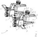
- FIG. 1is a perspective view of an orthopedic clamp device described herein.
- FIG. 2is an end view of the orthopedic clamp device of FIG. 1 .
- FIG. 3is a broken, partial transparent, perspective view of the orthopedic clamp device of FIG. 1 .
- FIG. 4is a broken second side view of the orthopedic clamp device of FIG. 1 .
- FIG. 5is a perspective view of the orthopedic clamp device of FIG. 1 , as applied to a fracture bone to retain reduction of the fracture while a bone plate is implanted.
- FIG. 6is a side elevation view of another embodiment of an orthopedic clamp device.
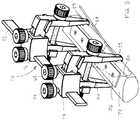
- FIG. 7is a perspective view of another embodiment of an orthopedic clamp device.
- FIG. 8is an end view of one clamp of the clamp device of FIG. 7 .
- FIG. 9is a cross-section through line 9 - 9 in FIG. 8 .
- FIG. 10is an assembly view of the clamp shown in FIG. 8 .
- FIG. 11is a side elevation of an assembled clamp device with first and second clamps angularly offset relative to each other.
- FIG. 12is a top view of the clamp device in the orientation of FIG. 11 .
- FIG. 13is an end perspective view of the clamp device in the orientation of FIG. 11 .
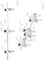
- FIG. 14is a side elevation of an assembled clamp device with three clamp angularly offset relative to each other.
- FIG. 15is a perspective view of the clamp device in the orientation of FIG. 14 .
- the clamping device 10generally includes a clamp connector 12 , and first and second clamps 14 , 16 displaceable relative to each other along the clamp connector.
- the clamp connectoris a rigid bar 12 .
- the bar 12preferably has a non-circular cross-section, and more preferably a generally rectangular cross-sectional shape.
- the rectangular cross-sectionhas a height greater than a width, with the width extending substantially parallel to the variable opening within each of the first and second clamps 14 , 16 .
- the clamp connector 12is made of a biocompatible stiff and rigid material.
- the first and second clamps 14 , 16are preferably longitudinally displaceable relative to each other along the clamp connector 12 , and lockable in respective spaced-apart positions, as described below.
- the first and second clamps 14 , 16preferably have a common construction. Therefore, clamp 14 will be described as follows, with it understood that clamp 16 preferably comprises like elements and assembly and has all the adjustability of clamp 14 , as described below.
- Clamp 14includes first and second clamping arms 20 , 22 .
- the first and second clamping arms 20 , 22each include a proximal mounting end 24 , 26 and a distal clamping end 28 , 30 .
- the clamping arms 20 , 22are preferably movable relative to each other about an axis of a pivot pin 32 at their mounting ends 24 , 26 to rotate the clamping ends 28 , 30 into a variable sized opening 34 of any dimension between maximum open and fully closed configurations.
- Exemplar maximum open dimensionsinclude 10-50 mm; such range of maximum sizes may be supported by a single clamp or clamps of different size.
- the clamp 14is oriented to the clamp connector 12 such that the size of opening 34 varies in a dimension transverse to the bar 12 .
- first and second holes 36 , 38are provided in the arms 20 , 22 , and a bolt 40 extends through the first and second holes.
- the holes 36 , 38have widthwise minor diameter substantially similar to the bolt 40 , and a heightwise major diameter that is slightly larger to permit clearance for rotation of the first and second clamping arms 20 , 22 relative to each other over the bolt 40 .
- the major diametermay be approximately 20 ⁇ 5 percent greater in dimension that the minor diameter.
- a nut 42is rotationally fixed relative to the second clamping arm 22 to facilitate advancement of the bolt 40 therethrough.
- the rotational fixationmay include arms 44 on the nut 42 that extend about the sides of the second clamping arm 22 or, alternatively, can include other means, by way of example, insertion of a non-circular nut into a rotationally interfering recess.
- the bolt 40includes a threaded shaft portion 46 , and a knurled head 48 and a hex socket 50 , both to further facilitate its manual and/or mechanical rotation relative to the first clamping arm 20 and the nut 42 .
- the threads 46 on the boltare preferably 8-32 or 6-32, which permit fine adjustment. Manual rotation of the head 48 is preferred so that the user feels the pressure imparted on the bone when clamping for tactile feedback.
- the first arm 20 about the first hole 36has a convex surface 52 so that as the first and second clamping arms 20 , 22 are rotated relative to each other between open and closed configurations, the first arm 20 has a consistently curved surface against which the head 48 makes tangential contact.
- a spring 54is provided to apply a force between the first and second clamping arms 20 , 22 to bias the arms toward the open configuration.
- the spring 54is preferably a compression spring extending coaxially over the bolt 40 and seating at each of its ends in recesses 56 at the insides of the first and second holes 36 , 38 .
- the clamping ends 28 , 30 of the first and second clamping arms 20 , 22include one or more teeth 58 to engage a bone and bone fragments so that the clamping arms 20 , 22 , when moved toward the closed configuration about the bone, can apply sufficient force against the bone fragments to maintain grip on bone or to maintain reduction of a bone fracture.
- a clearance of preferably 15-50 mmis provided from the distal tooth 58 to the bolt 40 .
- the clamping ends 28 , 30may also include angled slots 59 sized to receive auxiliary fixation devices such as K-wires or screws therethrough.
- the first and second clamping arms 20 , 22 of clamp 14are coupled to the clamp connector 12 via a mounting bracket 60 .
- the mounting bracket 60includes a curved internal guide channel 62 that receives curved tracks 64 extending laterally from the second clamping arm 22 .
- the second clamping arm 22can be advanced into and out of the guide channel to modify the angle at which the entire first clamp 14 is oriented relative to the clamp connector 12 .
- the second clamping arm 22and thus the clamp 14 , can preferably be rotated within a 20° to 45° arc relative to the clamp connector 12 , although other angular displacements are possible.
- a first threaded hole 66is provided in the mounting bracket 60 into communication with the guide channel 62 , and a first set screw 68 with manual knob is coupled within the first threaded hole 66 .
- the first set screw 68can be released to permit to the second clamping arm 22 to ride within the guide channel 62 , and rotated into contact with the second clamping arm to fix the position of the second clamping arm relative to the mounting bracket, and thus the angle of the first clamp 14 relative to the clamp connector 12 .
- a second threaded hole 70is provided in the mounting bracket into communication with a slot 72 that receives the clamp connector 12 , and a second set screw 74 with manual knob is coupled within the second threaded hole.
- the second set screw 74can be released to permit longitudinal movement of the mounting bracket 60 over the clamp connector 12 to displace the first clamp 14 relative to the second clamp 16 ; the second set screw 74 can then be rotated into contact with the clamp connector 12 to fix the position of the first clamp 14 relative to the second clamp 16 .
- the first and second clamps 14 , 16are preferably capable of being moved within 25 mm of each other, and preferably at least 100 mm apart from each other along the clamp connector 12 .
- the rotational displacement of the first and second clamping arms 20 , 22 of each of the first and second clamps 14 , 16 , the angular displacement of the first and second clamps 14 , 16 relative to their mounting bracket 60 and the clamp connector 12 , and the longitudinal displacement of the first and second clamps 14 , 16 along the clamp connector 12provide excellent configurability and adaptability to many bones and fracture conditions.
- the opening clearance 34 within the first and second clamps 14 , 16provides ample working space to manipulate bone reduction and insert and provide at least temporary fixation of a fracture fixation plate 76 onto the bone 78 without removal of the clamping device 10 ( FIG. 5 ).
- the bolts 40are loosened to permit the clamps 14 , 16 to have openings 34 of sufficient dimension to be received over the bone 72 .
- the first and second screws 68 , 74are also loosened to permit relative angular and longitudinal adjustment of the clamps 14 , 16 relative to each other.
- the fracture 80is reduced.
- the clamping device 10is positioned onto the bone 78 , with each clamp 14 , 16 located to hold the reduction.
- the loosened first and second screws 68 , 74allow the clamps 14 , 16 to be moved to an appropriate longitudinal and angular displacement to maintain the reduction.
- the bolt 40 on each clamp 14 , 16is sufficiently tightened to cause their clamping arms 20 , 22 to retain the reduction without providing excess compression that would displace bone fragments or otherwise operate counter to the procedure.
- the first and second screws 68 , 74are securely tightened to maintain the set configuration.
- One or more bone fixation devices 84may be inserted through holes 59 in the lower clamping ends of the clamping arms 20 , 22 and into bone therebetween for temporary stability of the bone. Then, the plate 76 can be positioned between the clamping arms 20 , 22 , under the bolt 40 , and onto the bone 78 . While the reduction is maintained with the clamping device 10 , the plate 76 is at least partially, and optionally fully secured to the bone.
- the fixation devices 84if used, are then removed. Then, the bolts 40 of the clamps 14 , 16 are loosened, allowing the arms 20 , 22 of each clamp to spread apart, and the clamping device 10 is removed.
- first and second clamping arms 20 , 22 of each clamp 14 , 16are hermaphroditic, and all features described with respect to either the first or second arms 20 , 22 are likewise provided to the other, such a configuration being shown in the figures. In this manner, a single arm construct may be utilized for assembly of both of the first and second clamping arms.
- each clamp 14 , 16 and mounting brackets 60may be made from a plastic, such as a transparent or translucent, radiolucent, polycarbonate which provides enhanced viewing of the bone 78 both visually to the surgeon and under fluoroscopy as a surgical procedure is being performed thereon.
- the clamps 14 , 16may be made from other polymers, including nylon or glass-filled polymers with high stiffness. Polymeric materials are lighter and provide a less massive and more manageable instrument. Further, such a device is readily adapted from a manufacturing cost perspective to be a single-use, disposable instrument.
- the clampsmay be made from a metal.
- the remaining components of the clamping device 10may be made from a suitable metal, such as a stainless steel, a suitable plastic, or a combination thereof.
- the clamp connector 112includes an articulation system 190 between the clamps 114 , 116 .
- the articulation system 190includes at least one, and preferably two, universal joints 192 , 194 , and an articulation bar 196 between the ball joints.
- Each joint 192 , 194permits displacement of the clamps 114 , 116 along x-, y- and z-axes relative to each other.
- the use of both joints 192 , 194 togetherpermits the clamps 114 , 116 to be displaced along parallel, non-coaxial axes.
- joints 114 , 116are shown as ball joints, other suitable joints and mechanisms permitting the described displacement can also be used.
- the clamps 114 , 116remain longitudinally displaceable along each of first and second portions 198 , 200 of the clamp connector.
- one of the clamps 114 , 116may be longitudinally fixed to one of the joints 192 , 194 , with all longitudinal displacement occurring at the other end of the clamp device 110 .
- Each clamp 214 , 216includes an integrated articulation system 290 that permits angular and rotational displacement of the clamp connector 212 relative to the respective clamp 214 , 216 .
- the articulation system 290is preferably a universal or ball joint that is adapted to provide a limited range of motion of the respective clamp 214 , 216 on the clamp connector 212 , e.g., at least ⁇ 15°, and more preferably ⁇ 30°, relative to a normal axis A to a plane of the respective clamp 214 , 216 .
- the connector bar 212is coaxial with the normal axis A.
- the articulation system 290includes an opening 292 formed in the upper end of clamp arm 222 .
- Opening 292includes an inner first portion 294 defining a flat 293 and a spherical surface 295 forming a portion of a socket for a ball structure 296 , an outer cylindrical bore portion 298 , transverse openings 300 , 302 for passage of the clamp connector 212 , and an upper threaded bore 303 .
- a socket insert 304 defining a flat 305 and a spherical surface 306 forming a remainder of the socket for the ball structure 296is provided into the bore portion 298 and captures the ball structure 296 .
- the socket inert 304 insertis captured and retained with pins 308 fixed in clamp arm holes 309 and insert holes 311 ( FIG. 10 ).
- the ball structure 296comprises upper and lower generally hemispherical elements 310 , 312 which together define an axial passage 314 for the clamp connector 212 and lateral flats 316 , 318 ( FIGS. 9 and 10 ).
- Hemispherical elements 310 , 312may be free floating within the socket, or may be retained in a spaced apart configuration, e.g., with one or more spring elements (not shown).
- the lateral flats 316 , 318face corresponding flats 293 , 305 on the first portion 294 and the socket insert 304 , but are slightly spaced apart therefrom in a neutral position.
- the facing flats 293 , 316 , and 305 , 318interfere when the ball structure 296 is laterally angularly displaced by more than a predetermined amount, such as 15° from normal, to function as a stop for maximum angular displacement.
- the clamp connector 212is positioned through the axial passages 314 of both clamps 214 , 216 .
- the ends 212 a , 212 b of the clamp connector 212may be rounded or otherwise tapered to facilitate insertion through the axial passage 314 .
- the axial passages 314may be defined as round (as shown) or optionally the clamp connector 212 and axial passages 314 may have interfering cross-sectional shapes, e.g., square or hexagonal, such that relative rotation between the clamp connector 212 and the ball structure 296 of the clamps 214 , 216 is prohibited.
- a locking screw 320is inserted into the threaded bore 303 and can be advanced to tighten the ball structure 296 about the clamp connector 212 and lock the ball structure 296 relative to the clamp 214 ; or loosened to permit repositioning of the ball structure 296 along the clamp connector 212 and/or the angular position of the clamp 214 relative to the ball structure.
- FIGS. 11 through 13show the clamps angularly displaced relative to each other.
- the clamp devicecan also be used with more than two clamps and more than two clamp connectors. Turning now to FIGS. 14 and 15 , an assembly of a device 410 is shown using three clamps 414 , 415 , 416 and two clamp connectors 412 , 413 .
- Clamps 414 , 416include, as described above with clamps 14 , 114 and 214 , a socket or other structure at one side of the clamp in which to receive a clamp connector.
- clamp 415is a double-connecting clamp, including a socket 514 , 515 or suitable structure in which to receive clamp connectors 412 , 413 at both sides of the clamp; i.e., in each clamp arm 422 , 424 .
- clamps 414 and/or 416can be replaced with double-connecting clamps, such that additional clamp connectors can be added to assemble a clamping device of appropriate length for a procedure.
- other clampsneed not independently articulate relative to the clamp connectors to which they are attached is order to have a high degree of adjustment for most applications.
- knobs effecting and releasing longitudinal fixation of the clamps along the clamp connectorare shown positioned at the upper side of the clamping device, the knobs may be provided along a lateral or lower side of the clamping device. Further, while the knobs effecting and releasing angular fixation of the first and second arms of the clamps are shown positioned at the upper side of the clamping device, the knobs may be provided along a lateral side of each clamp.
- clamping deviceWhile various materials have been disclosed for manufacture of the clamping device, other suitable materials can be used and may be appropriate depending on whether the clamping device is intended as a single-use disposable or multi-use re-usable surgical device. Moreover, the clamping device may be provided in various sizes so as to be adapted to maintain reduction on bones of different portions of the human body, on human bodies of different size, and even non-human mammalian and other animal bodies. It will therefore be appreciated by those skilled in the art that yet other modifications could be made to the provided invention without deviating from its scope as claimed.
Landscapes
- Health & Medical Sciences (AREA)
- Life Sciences & Earth Sciences (AREA)
- Orthopedic Medicine & Surgery (AREA)
- Surgery (AREA)
- Biomedical Technology (AREA)
- Engineering & Computer Science (AREA)
- Nuclear Medicine, Radiotherapy & Molecular Imaging (AREA)
- Heart & Thoracic Surgery (AREA)
- Medical Informatics (AREA)
- Molecular Biology (AREA)
- Animal Behavior & Ethology (AREA)
- General Health & Medical Sciences (AREA)
- Public Health (AREA)
- Veterinary Medicine (AREA)
- Surgical Instruments (AREA)
Abstract
Description
Claims (31)
Priority Applications (1)
| Application Number | Priority Date | Filing Date | Title |
|---|---|---|---|
| US16/155,567US10806499B2 (en) | 2017-10-10 | 2018-10-09 | Universal orthopedic clamp |
Applications Claiming Priority (2)
| Application Number | Priority Date | Filing Date | Title |
|---|---|---|---|
| US201762570390P | 2017-10-10 | 2017-10-10 | |
| US16/155,567US10806499B2 (en) | 2017-10-10 | 2018-10-09 | Universal orthopedic clamp |
Publications (2)
| Publication Number | Publication Date |
|---|---|
| US20190105092A1 US20190105092A1 (en) | 2019-04-11 |
| US10806499B2true US10806499B2 (en) | 2020-10-20 |
Family
ID=65992826
Family Applications (1)
| Application Number | Title | Priority Date | Filing Date |
|---|---|---|---|
| US16/155,567ActiveUS10806499B2 (en) | 2017-10-10 | 2018-10-09 | Universal orthopedic clamp |
Country Status (2)
| Country | Link |
|---|---|
| US (1) | US10806499B2 (en) |
| WO (1) | WO2019074722A2 (en) |
Cited By (90)
| Publication number | Priority date | Publication date | Assignee | Title |
|---|---|---|---|---|
| US11311306B2 (en) | 2017-12-28 | 2022-04-26 | Cilag Gmbh International | Surgical systems for detecting end effector tissue distribution irregularities |
| USD950728S1 (en) | 2019-06-25 | 2022-05-03 | Cilag Gmbh International | Surgical staple cartridge |
| US11317915B2 (en) | 2019-02-19 | 2022-05-03 | Cilag Gmbh International | Universal cartridge based key feature that unlocks multiple lockout arrangements in different surgical staplers |
| US11324557B2 (en) | 2017-12-28 | 2022-05-10 | Cilag Gmbh International | Surgical instrument with a sensing array |
| US11331100B2 (en) | 2019-02-19 | 2022-05-17 | Cilag Gmbh International | Staple cartridge retainer system with authentication keys |
| US11337746B2 (en) | 2018-03-08 | 2022-05-24 | Cilag Gmbh International | Smart blade and power pulsing |
| US11344326B2 (en) | 2018-03-08 | 2022-05-31 | Cilag Gmbh International | Smart blade technology to control blade instability |
| US11357503B2 (en) | 2019-02-19 | 2022-06-14 | Cilag Gmbh International | Staple cartridge retainers with frangible retention features and methods of using same |
| US11364075B2 (en) | 2017-12-28 | 2022-06-21 | Cilag Gmbh International | Radio frequency energy device for delivering combined electrical signals |
| US11382697B2 (en) | 2017-12-28 | 2022-07-12 | Cilag Gmbh International | Surgical instruments comprising button circuits |
| US11389164B2 (en) | 2017-12-28 | 2022-07-19 | Cilag Gmbh International | Method of using reinforced flexible circuits with multiple sensors to optimize performance of radio frequency devices |
| US11406390B2 (en) | 2017-10-30 | 2022-08-09 | Cilag Gmbh International | Clip applier comprising interchangeable clip reloads |
| US11410259B2 (en) | 2017-12-28 | 2022-08-09 | Cilag Gmbh International | Adaptive control program updates for surgical devices |
| US11424027B2 (en) | 2017-12-28 | 2022-08-23 | Cilag Gmbh International | Method for operating surgical instrument systems |
| US11419667B2 (en) | 2017-12-28 | 2022-08-23 | Cilag Gmbh International | Ultrasonic energy device which varies pressure applied by clamp arm to provide threshold control pressure at a cut progression location |
| US11423007B2 (en) | 2017-12-28 | 2022-08-23 | Cilag Gmbh International | Adjustment of device control programs based on stratified contextual data in addition to the data |
| US11430355B2 (en)* | 2018-07-18 | 2022-08-30 | Sport Clamps, Inc. | Display clamp |
| US11432885B2 (en) | 2017-12-28 | 2022-09-06 | Cilag Gmbh International | Sensing arrangements for robot-assisted surgical platforms |
| US11446052B2 (en) | 2017-12-28 | 2022-09-20 | Cilag Gmbh International | Variation of radio frequency and ultrasonic power level in cooperation with varying clamp arm pressure to achieve predefined heat flux or power applied to tissue |
| USD964564S1 (en) | 2019-06-25 | 2022-09-20 | Cilag Gmbh International | Surgical staple cartridge retainer with a closure system authentication key |
| US11464559B2 (en) | 2017-12-28 | 2022-10-11 | Cilag Gmbh International | Estimating state of ultrasonic end effector and control system therefor |
| US11464511B2 (en) | 2019-02-19 | 2022-10-11 | Cilag Gmbh International | Surgical staple cartridges with movable authentication key arrangements |
| US11464535B2 (en) | 2017-12-28 | 2022-10-11 | Cilag Gmbh International | Detection of end effector emersion in liquid |
| US11471156B2 (en) | 2018-03-28 | 2022-10-18 | Cilag Gmbh International | Surgical stapling devices with improved rotary driven closure systems |
| US11504192B2 (en) | 2014-10-30 | 2022-11-22 | Cilag Gmbh International | Method of hub communication with surgical instrument systems |
| US11510741B2 (en) | 2017-10-30 | 2022-11-29 | Cilag Gmbh International | Method for producing a surgical instrument comprising a smart electrical system |
| US11529187B2 (en) | 2017-12-28 | 2022-12-20 | Cilag Gmbh International | Surgical evacuation sensor arrangements |
| US11540855B2 (en) | 2017-12-28 | 2023-01-03 | Cilag Gmbh International | Controlling activation of an ultrasonic surgical instrument according to the presence of tissue |
| US11559308B2 (en) | 2017-12-28 | 2023-01-24 | Cilag Gmbh International | Method for smart energy device infrastructure |
| US11559307B2 (en) | 2017-12-28 | 2023-01-24 | Cilag Gmbh International | Method of robotic hub communication, detection, and control |
| US11564703B2 (en) | 2017-10-30 | 2023-01-31 | Cilag Gmbh International | Surgical suturing instrument comprising a capture width which is larger than trocar diameter |
| US11564756B2 (en) | 2017-10-30 | 2023-01-31 | Cilag Gmbh International | Method of hub communication with surgical instrument systems |
| US11571234B2 (en) | 2017-12-28 | 2023-02-07 | Cilag Gmbh International | Temperature control of ultrasonic end effector and control system therefor |
| US11576677B2 (en) | 2017-12-28 | 2023-02-14 | Cilag Gmbh International | Method of hub communication, processing, display, and cloud analytics |
| US11589932B2 (en) | 2017-12-28 | 2023-02-28 | Cilag Gmbh International | Usage and technique analysis of surgeon / staff performance against a baseline to optimize device utilization and performance for both current and future procedures |
| US11589888B2 (en) | 2017-12-28 | 2023-02-28 | Cilag Gmbh International | Method for controlling smart energy devices |
| US11589865B2 (en) | 2018-03-28 | 2023-02-28 | Cilag Gmbh International | Methods for controlling a powered surgical stapler that has separate rotary closure and firing systems |
| US11601371B2 (en) | 2017-12-28 | 2023-03-07 | Cilag Gmbh International | Surgical network determination of prioritization of communication, interaction, or processing based on system or device needs |
| US11596291B2 (en) | 2017-12-28 | 2023-03-07 | Cilag Gmbh International | Method of compressing tissue within a stapling device and simultaneously displaying of the location of the tissue within the jaws |
| US11602393B2 (en) | 2017-12-28 | 2023-03-14 | Cilag Gmbh International | Surgical evacuation sensing and generator control |
| US11612444B2 (en) | 2017-12-28 | 2023-03-28 | Cilag Gmbh International | Adjustment of a surgical device function based on situational awareness |
| US11612408B2 (en) | 2017-12-28 | 2023-03-28 | Cilag Gmbh International | Determining tissue composition via an ultrasonic system |
| US11659023B2 (en) | 2017-12-28 | 2023-05-23 | Cilag Gmbh International | Method of hub communication |
| US11666331B2 (en) | 2017-12-28 | 2023-06-06 | Cilag Gmbh International | Systems for detecting proximity of surgical end effector to cancerous tissue |
| US11678881B2 (en) | 2017-12-28 | 2023-06-20 | Cilag Gmbh International | Spatial awareness of surgical hubs in operating rooms |
| US11696760B2 (en) | 2017-12-28 | 2023-07-11 | Cilag Gmbh International | Safety systems for smart powered surgical stapling |
| US11701185B2 (en) | 2017-12-28 | 2023-07-18 | Cilag Gmbh International | Wireless pairing of a surgical device with another device within a sterile surgical field based on the usage and situational awareness of devices |
| US11701139B2 (en) | 2018-03-08 | 2023-07-18 | Cilag Gmbh International | Methods for controlling temperature in ultrasonic device |
| US11737668B2 (en) | 2017-12-28 | 2023-08-29 | Cilag Gmbh International | Communication hub and storage device for storing parameters and status of a surgical device to be shared with cloud based analytics systems |
| US11744604B2 (en) | 2017-12-28 | 2023-09-05 | Cilag Gmbh International | Surgical instrument with a hardware-only control circuit |
| US11751958B2 (en) | 2017-12-28 | 2023-09-12 | Cilag Gmbh International | Surgical hub coordination of control and communication of operating room devices |
| US11771487B2 (en) | 2017-12-28 | 2023-10-03 | Cilag Gmbh International | Mechanisms for controlling different electromechanical systems of an electrosurgical instrument |
| US11775682B2 (en) | 2017-12-28 | 2023-10-03 | Cilag Gmbh International | Data stripping method to interrogate patient records and create anonymized record |
| US11786251B2 (en) | 2017-12-28 | 2023-10-17 | Cilag Gmbh International | Method for adaptive control schemes for surgical network control and interaction |
| US11786245B2 (en) | 2017-12-28 | 2023-10-17 | Cilag Gmbh International | Surgical systems with prioritized data transmission capabilities |
| US11801098B2 (en) | 2017-10-30 | 2023-10-31 | Cilag Gmbh International | Method of hub communication with surgical instrument systems |
| US11818052B2 (en) | 2017-12-28 | 2023-11-14 | Cilag Gmbh International | Surgical network determination of prioritization of communication, interaction, or processing based on system or device needs |
| US11832840B2 (en) | 2017-12-28 | 2023-12-05 | Cilag Gmbh International | Surgical instrument having a flexible circuit |
| US11832899B2 (en) | 2017-12-28 | 2023-12-05 | Cilag Gmbh International | Surgical systems with autonomously adjustable control programs |
| US11857152B2 (en) | 2017-12-28 | 2024-01-02 | Cilag Gmbh International | Surgical hub spatial awareness to determine devices in operating theater |
| US11864728B2 (en) | 2017-12-28 | 2024-01-09 | Cilag Gmbh International | Characterization of tissue irregularities through the use of mono-chromatic light refractivity |
| US11871901B2 (en) | 2012-05-20 | 2024-01-16 | Cilag Gmbh International | Method for situational awareness for surgical network or surgical network connected device capable of adjusting function based on a sensed situation or usage |
| US11890065B2 (en) | 2017-12-28 | 2024-02-06 | Cilag Gmbh International | Surgical system to limit displacement |
| US11896443B2 (en) | 2017-12-28 | 2024-02-13 | Cilag Gmbh International | Control of a surgical system through a surgical barrier |
| US11896322B2 (en) | 2017-12-28 | 2024-02-13 | Cilag Gmbh International | Sensing the patient position and contact utilizing the mono-polar return pad electrode to provide situational awareness to the hub |
| US11903587B2 (en) | 2017-12-28 | 2024-02-20 | Cilag Gmbh International | Adjustment to the surgical stapling control based on situational awareness |
| US11903601B2 (en) | 2017-12-28 | 2024-02-20 | Cilag Gmbh International | Surgical instrument comprising a plurality of drive systems |
| US11911045B2 (en) | 2017-10-30 | 2024-02-27 | Cllag GmbH International | Method for operating a powered articulating multi-clip applier |
| US11931027B2 (en) | 2018-03-28 | 2024-03-19 | Cilag Gmbh Interntional | Surgical instrument comprising an adaptive control system |
| US11937769B2 (en) | 2017-12-28 | 2024-03-26 | Cilag Gmbh International | Method of hub communication, processing, storage and display |
| US11969216B2 (en) | 2017-12-28 | 2024-04-30 | Cilag Gmbh International | Surgical network recommendations from real time analysis of procedure variables against a baseline highlighting differences from the optimal solution |
| US11998193B2 (en) | 2017-12-28 | 2024-06-04 | Cilag Gmbh International | Method for usage of the shroud as an aspect of sensing or controlling a powered surgical device, and a control algorithm to adjust its default operation |
| US12009095B2 (en) | 2017-12-28 | 2024-06-11 | Cilag Gmbh International | Real-time analysis of comprehensive cost of all instrumentation used in surgery utilizing data fluidity to track instruments through stocking and in-house processes |
| US12029506B2 (en) | 2017-12-28 | 2024-07-09 | Cilag Gmbh International | Method of cloud based data analytics for use with the hub |
| US12035890B2 (en) | 2017-12-28 | 2024-07-16 | Cilag Gmbh International | Method of sensing particulate from smoke evacuated from a patient, adjusting the pump speed based on the sensed information, and communicating the functional parameters of the system to the hub |
| US12048496B2 (en) | 2017-12-28 | 2024-07-30 | Cilag Gmbh International | Adaptive control program updates for surgical hubs |
| US12062442B2 (en) | 2017-12-28 | 2024-08-13 | Cilag Gmbh International | Method for operating surgical instrument systems |
| US12076010B2 (en) | 2017-12-28 | 2024-09-03 | Cilag Gmbh International | Surgical instrument cartridge sensor assemblies |
| US12127729B2 (en) | 2017-12-28 | 2024-10-29 | Cilag Gmbh International | Method for smoke evacuation for surgical hub |
| US12133773B2 (en) | 2017-12-28 | 2024-11-05 | Cilag Gmbh International | Surgical hub and modular device response adjustment based on situational awareness |
| US12137991B2 (en) | 2017-12-28 | 2024-11-12 | Cilag Gmbh International | Display arrangements for robot-assisted surgical platforms |
| US12193766B2 (en) | 2017-12-28 | 2025-01-14 | Cilag Gmbh International | Situationally aware surgical system configured for use during a surgical procedure |
| US12226151B2 (en) | 2017-12-28 | 2025-02-18 | Cilag Gmbh International | Capacitive coupled return path pad with separable array elements |
| US12303159B2 (en) | 2018-03-08 | 2025-05-20 | Cilag Gmbh International | Methods for estimating and controlling state of ultrasonic end effector |
| US12310586B2 (en) | 2017-12-28 | 2025-05-27 | Cilag Gmbh International | Method for adaptive control schemes for surgical network control and interaction |
| US12318152B2 (en) | 2017-12-28 | 2025-06-03 | Cilag Gmbh International | Computer implemented interactive surgical systems |
| US12329467B2 (en) | 2017-10-30 | 2025-06-17 | Cilag Gmbh International | Method of hub communication with surgical instrument systems |
| US12376855B2 (en) | 2017-12-28 | 2025-08-05 | Cilag Gmbh International | Safety systems for smart powered surgical stapling |
| US12396806B2 (en) | 2017-12-28 | 2025-08-26 | Cilag Gmbh International | Adjustment of a surgical device function based on situational awareness |
| US12433508B2 (en) | 2017-12-28 | 2025-10-07 | Cilag Gmbh International | Surgical system having a surgical instrument controlled based on comparison of sensor and database data |
Families Citing this family (7)
| Publication number | Priority date | Publication date | Assignee | Title |
|---|---|---|---|---|
| WO2019074722A2 (en)* | 2017-10-10 | 2019-04-18 | Miki Roberto Augusto | Universal orthopedic clamp |
| US11344352B2 (en) | 2019-03-29 | 2022-05-31 | Depuy Ireland Unlimited Company | Methods of operating a surgical instrument and performing a surgical procedure to balance a patient's knee |
| US12433656B2 (en) | 2019-03-29 | 2025-10-07 | Depuy Ireland Unlimited Company | Methods, surgical instruments, and associated systems for performing a surgical procedure to balance a patient's knee |
| US20210338299A1 (en)* | 2020-04-29 | 2021-11-04 | Smith & Nephew, Inc. | Anatomical structure mounting apparatuses |
| CN115153804B (en)* | 2022-06-24 | 2025-01-24 | 上海焰医数字医疗科技有限公司 | Bone clamp structure and bone clamp system |
| CN119326519A (en)* | 2023-07-19 | 2025-01-21 | 中国人民解放军总医院第四医学中心 | Osteotomy guide |
| CN118044870B (en)* | 2024-04-16 | 2024-06-28 | 四川大学华西医院 | Spinal column dislocation resetting device |
Citations (119)
| Publication number | Priority date | Publication date | Assignee | Title |
|---|---|---|---|---|
| US842007A (en)* | 1906-11-08 | 1907-01-22 | Ralph Parker | Pipe-clamp. |
| US852180A (en)* | 1907-03-15 | 1907-04-30 | Anna M Hoffman | Bedclothes-fastener. |
| US1766546A (en)* | 1928-11-13 | 1930-06-24 | Axel H Roos | Combination calipers |
| US1782752A (en)* | 1929-02-26 | 1930-11-25 | F J Hagerling | Wrench |
| US1985108A (en)* | 1933-12-18 | 1934-12-18 | Henry P Rush | Surgical instrument |
| US2168257A (en)* | 1937-07-19 | 1939-08-01 | Cincinnati Tool Company | Clamp |
| US2190143A (en)* | 1937-05-14 | 1940-02-13 | Walter C Barnes | Mechanical clamp |
| US2225875A (en)* | 1940-04-17 | 1940-12-24 | Liebmann Moses | Blanket fastener |
| US2362957A (en)* | 1941-09-27 | 1944-11-14 | Harry Herschel Leiter | Surgical bone clamp |
| US2427128A (en)* | 1946-01-28 | 1947-09-09 | Zimmer Mfg Company | Surgical bone clamp |
| US2460470A (en)* | 1946-11-27 | 1949-02-01 | Rogers Samuel Perry | Holding tool |
| US2583896A (en)* | 1949-09-06 | 1952-01-29 | Siebrandt Inc | Bone clamp |
| US2631585A (en)* | 1949-09-06 | 1953-03-17 | Siebrandt Francture Equipment | Bone reducing tool |
| US2669958A (en)* | 1951-04-18 | 1954-02-23 | Joseph R Hague | Welder's work-holding appliance |
| US2913792A (en)* | 1958-01-27 | 1959-11-24 | Elvin S Land | Garment holder |
| US3477429A (en)* | 1967-06-30 | 1969-11-11 | Sampson Corp | Extra-cortical clamp with detachable tensioning tool for internal fixation of bone fractures |
| US3604069A (en)* | 1970-04-01 | 1971-09-14 | Pacific Plantronics Inc | Cable strain relief device |
| US3609638A (en)* | 1970-06-03 | 1971-09-28 | John J Darrey | Extension cord coupling clamp assembly |
| US3727272A (en)* | 1970-10-15 | 1973-04-17 | P Rhodes | Flexible material holding device |
| US3736629A (en)* | 1971-03-16 | 1973-06-05 | J Blake | Clamping device |
| USRE27986E (en)* | 1973-05-29 | 1974-04-23 | Cable strain relief device | |
| US4187840A (en)* | 1978-08-14 | 1980-02-12 | Watanabe Robert S | Bone plate clamp |
| US4611582A (en) | 1983-12-27 | 1986-09-16 | Wisconsin Alumni Research Foundation | Vertebral clamp |
| US5133342A (en)* | 1990-12-26 | 1992-07-28 | Seaton James I | Lever to align bones |
| US5302039A (en)* | 1992-08-11 | 1994-04-12 | Omholt Bruce D | Panel coupler |
| US5312403A (en)* | 1991-05-03 | 1994-05-17 | Synthes (U.S.A.) | External fixation device |
| US5342364A (en)* | 1993-05-17 | 1994-08-30 | Mikhail Michael W E | Patellar implant stem trimmer |
| US5578032A (en)* | 1994-12-20 | 1996-11-26 | Accurate Surgical & Scientific Instruments Corporation | Bone clamp |
| US5645548A (en)* | 1996-02-15 | 1997-07-08 | Augsburger; Samuel F. | Osteotomy frame |
| US5797919A (en)* | 1996-07-16 | 1998-08-25 | Brinson; Keith Anthony | Surgical bone clamp |
| US5885298A (en)* | 1994-02-23 | 1999-03-23 | Biomet, Inc. | Patellar clamp and reamer with adjustable stop |
| US5951556A (en) | 1996-05-15 | 1999-09-14 | Orthofix S.R.L. | Compact external fixation device |
| US6171307B1 (en) | 1999-03-23 | 2001-01-09 | Orlich Jose Luis | Bone stabilizer and method |
| US6171308B1 (en) | 1995-05-12 | 2001-01-09 | Kirk Jay Bailey | Method and apparatus for external fixation of large bones |
| US6221072B1 (en) | 1997-11-03 | 2001-04-24 | Gerrit Johannes Termaten | Device for fixing bone sections relative to each other |
| US6287307B1 (en)* | 2000-07-31 | 2001-09-11 | Shalom Y. Abboudi | Apparatus and methods for clamping split bone sections |
| US6315780B1 (en)* | 1999-04-12 | 2001-11-13 | Accurate Surgical & Scientific Instruments Corporation | Bone clamp for dynamic and non-dynamic compression of transverse fractures and method of use thereof |
| US20010053911A1 (en)* | 1998-09-17 | 2001-12-20 | Marcus Hehli | Repositioning instrument to fixate bone-fractures |
| US6387097B1 (en)* | 1997-05-16 | 2002-05-14 | Scient'x Societe A Responsabilite Limitee | Implant for osteosynthesis device with hook |
| US6443955B1 (en)* | 1998-11-25 | 2002-09-03 | Alliance Orthopedic, Inc. | Fracture reduction clamp |
| US20030004513A1 (en)* | 2001-06-27 | 2003-01-02 | Guzman Pamela C. | Method and apparatus for use in the performance of endoscopic minimally invasive orthopaedic plating procedures |
| US20030080267A1 (en)* | 2001-10-29 | 2003-05-01 | Panavision, Inc. | Multi-sized clamp |
| US6579296B1 (en)* | 1998-03-13 | 2003-06-17 | Theodore I. Macey | Method and apparatus for clamping |
| US20030149430A1 (en)* | 2002-02-04 | 2003-08-07 | Joseph Ferrante | Devices, systems, and methods for placing and positioning fixation elements in external fixation systems |
| US6605088B1 (en)* | 2000-03-15 | 2003-08-12 | Richard A. St. Onge | Bone setting apparatus and method |
| US6702824B2 (en)* | 1999-09-10 | 2004-03-09 | Depuy Orthopaedics, Inc. | Prosthesis positioning apparatus |
| US20040055429A1 (en)* | 2002-09-23 | 2004-03-25 | Winkler John Andrew | Locking pliers tool with automatic jaw gap adjustment and adjustable clamping force capability |
| US20040232608A1 (en)* | 2003-05-23 | 2004-11-25 | Harry Wong | Quick release cantilever clamp |
| US20050149028A1 (en) | 2003-12-29 | 2005-07-07 | Alec Birkbeck | Bone clamp |
| US20060116679A1 (en)* | 2004-11-30 | 2006-06-01 | Stryker Trauma Sa | Bone plating implants, instruments and methods |
| US7147639B2 (en) | 2000-05-26 | 2006-12-12 | Orthofix S.R.L. | Disposable external fixation device |
| US20080009871A1 (en)* | 2006-06-27 | 2008-01-10 | Orbay Jorge L | Bone Plate Clamp |
| US20080221625A1 (en)* | 2007-03-08 | 2008-09-11 | Cas Innovations Ag | Medical Clamp, in Particular Spinal Clamp, Device for Providing a Reference Position and Method for Determining a Reference Position |
| US20090024127A1 (en)* | 2007-07-17 | 2009-01-22 | Christian Lechner | Radiolucent reference for computer-assisted surgery |
| US20090030462A1 (en)* | 2007-07-26 | 2009-01-29 | Glenn R. Buttermann, M.D. | Segmental Orthopaedic device for spinal elongation and for treatment of Scoliosis |
| US20090062869A1 (en)* | 2007-08-28 | 2009-03-05 | Perception Raisonnement Action En Medecine | Minimally invasive bone fixation clamp for navigated surgeries |
| US20090118775A1 (en)* | 2007-11-01 | 2009-05-07 | Burke Shawn M | Sternal Clamp |
| US20090187217A1 (en)* | 2008-01-18 | 2009-07-23 | Mark Weiman | Transverse Connector |
| US7881771B2 (en) | 2005-08-03 | 2011-02-01 | The Hong Kong Polytechnic University | Bone reposition device, method and system |
| US20110066151A1 (en)* | 2009-09-11 | 2011-03-17 | Stryker Trauma Sa | External fixation component |
| US20110106183A1 (en)* | 2008-07-29 | 2011-05-05 | Dell Oca Alberto A Fernandez | Plate Holding Bone Forceps and Method of Use |
| US20110118750A1 (en)* | 2009-11-18 | 2011-05-19 | Accumis Inc. | Universal direction medical positioning structure |
| US20110137353A1 (en)* | 2007-07-26 | 2011-06-09 | Buttermann Glenn R | Segmental orthopedic device for spinal elongation and for treatment of scoliosis |
| US20110257657A1 (en) | 2007-06-25 | 2011-10-20 | Smith & Nephew, Inc. | Medical aligning device |
| US20110270314A1 (en)* | 2008-09-12 | 2011-11-03 | Marcel Mueller | Spinal stabilizing and guiding fixation system |
| EP2436324A1 (en) | 2010-09-30 | 2012-04-04 | Amenduni Gresele, Massimo | Instrument for surgical interventions, particularly orthopedic surgery |
| US20120093575A1 (en)* | 2010-10-07 | 2012-04-19 | Stryker Trauma Sa | Coupling element for an external fixator |
| US20120130384A1 (en)* | 2009-08-04 | 2012-05-24 | University Of South Florida | Apparatus for Osteotomy and Graft Preparation |
| US8192449B2 (en)* | 2005-10-25 | 2012-06-05 | Brainlab Ag | Non-penetrating fixing device |
| US8231623B1 (en)* | 2009-11-23 | 2012-07-31 | Christopher Jordan | Bone reduction and plate clamp assembly |
| US8230863B2 (en)* | 2006-05-30 | 2012-07-31 | Mini-Lap Technologies, Inc. | Platform for fixing surgical instruments during surgery |
| US20120221059A1 (en)* | 2010-06-18 | 2012-08-30 | The Curators Of The University Of Missouri | Cervical spine clamp |
| US20120271366A1 (en)* | 2011-04-19 | 2012-10-25 | Biomet Manufacturing Corp. | Patient-specific fracture fixation instrumentation and method |
| US20130025093A1 (en)* | 2011-07-28 | 2013-01-31 | Eric Liao | Clip Assembly |
| US8388619B2 (en) | 2002-09-17 | 2013-03-05 | Sixfix Inc. | Unilateral fixator |
| US20130116733A1 (en)* | 2011-11-07 | 2013-05-09 | Edward Jordan Stoll, JR. | Bone Clamp and Method |
| US20130131738A1 (en)* | 2011-05-10 | 2013-05-23 | Sean Powell | Bone fracture fixation clamp |
| US20130165939A1 (en)* | 2011-02-14 | 2013-06-27 | Imds Corporation | Patient Specific Implants and Instrumentation For Patellar Prostheses |
| US20130261674A1 (en)* | 2012-03-30 | 2013-10-03 | Daniel Duane Fritzinger | Bone plate positioning device |
| US8579950B1 (en)* | 2009-12-22 | 2013-11-12 | Christopher Jordan | Bone reduction and plate clamp assembly |
| US20130345762A1 (en)* | 2012-06-20 | 2013-12-26 | DePuy Synthes Products, LLC | Soft tissue bone reduction forceps |
| US8685037B1 (en)* | 2009-12-22 | 2014-04-01 | Christopher Jordan | Bone reduction and plate clamp assembly |
| US20140094818A1 (en)* | 2012-09-28 | 2014-04-03 | Matthew S. Wallace | Patella drill guide and trial surgical instrument having an alignment bore formed therein and method of using the same |
| CN103976773A (en) | 2014-06-04 | 2014-08-13 | 马秋野 | Reduction forceps |
| US20150032158A1 (en)* | 2013-07-25 | 2015-01-29 | Amendia Inc. | Percutaneous Pedicle Screw Revision System |
| US20150031985A1 (en)* | 2013-07-25 | 2015-01-29 | Medtronic Navigation, Inc. | Method and Apparatus for Moving a Reference Device |
| US20150209939A1 (en)* | 2014-01-28 | 2015-07-30 | Ho Chi-Fu | Adjustable Positioning Fixture |
| US20150209093A1 (en)* | 2014-01-27 | 2015-07-30 | James Dallis | Implantable medical device for restoring alignment and stabilizing bone fractures and methods of using the same |
| US9131974B1 (en)* | 2014-04-28 | 2015-09-15 | Boyer Anderson, LLC | Device for facilitating artificial prosthesis installation with measured applied pressure and method therefor |
| US20160015430A1 (en)* | 2013-03-11 | 2016-01-21 | Dynamic Spine, Llc | Screw-clamp orthopedic device and methods of implementation |
| US20160128730A1 (en)* | 2014-03-19 | 2016-05-12 | Yingze Zhang | Stress-dispersing fixing and connecting apparatus for anterior superior iliac spine and iliac crest |
| US9402746B2 (en)* | 2014-08-01 | 2016-08-02 | Boyer Anderson, LLC | Device for facilitating artificial prosthesis installation with measured applied pressure and method therefor |
| US20160249952A1 (en)* | 2015-02-27 | 2016-09-01 | Fixx Orthopedics, LLC | Orthopedic external fixation device |
| CN106037882A (en) | 2016-06-17 | 2016-10-26 | 李存玉 | Fixation forceps for department of orthopedics |
| US20160346097A1 (en)* | 2014-08-01 | 2016-12-01 | Boyer Anderson, LLC | Contact Surface Adapter and Components for Artificial Prosthesis Installation Clamp |
| US20160374694A1 (en)* | 2015-06-29 | 2016-12-29 | Smith & Nephew, Inc. | Graft placement system and method |
| US9550277B1 (en)* | 2014-10-17 | 2017-01-24 | Matthew E. Williams | Alignment and adjustment clamp |
| US9554813B2 (en)* | 2012-09-28 | 2017-01-31 | Depuy Ireland Unlimited Company | Patella drill guide and trial surgical instrument |
| US9572590B2 (en)* | 2006-10-03 | 2017-02-21 | Biomet Uk Limited | Surgical instrument |
| US20170113330A1 (en)* | 2014-10-17 | 2017-04-27 | Matthew E. Williams | Alignment and adjustment clamp |
| US20170156757A1 (en)* | 2015-12-03 | 2017-06-08 | Globus Medical, Inc. | External fixator assembly |
| US20170156892A1 (en)* | 2012-09-27 | 2017-06-08 | DePuy Synthes Products, Inc. | Acetabular orthopaedic surgical instrument and method of using same |
| US20170252069A1 (en)* | 2015-12-03 | 2017-09-07 | Globus Medical, Inc. | External fixator assembly |
| US20170281202A1 (en)* | 2016-03-31 | 2017-10-05 | Howmedica Osteonics Corp. | Navigated patella clamp |
| US20170296248A1 (en)* | 2016-04-15 | 2017-10-19 | Stryker European Holdings I, Llc | Distraction and compression in one plier |
| US20180092667A1 (en)* | 2016-03-17 | 2018-04-05 | Brainlab Ag | Bone clamp |
| US20180110542A1 (en)* | 2016-10-26 | 2018-04-26 | SIGN Fracture Care International | Bone fixation system and method using a clamping instrument to guide fastener placement |
| US20180132909A1 (en)* | 2016-11-16 | 2018-05-17 | Alphatec Spine, Inc. | Adjustable hook |
| US20180168699A1 (en)* | 2016-12-16 | 2018-06-21 | Nuvasive, Inc. | Bone hook apparatus |
| US20180168707A1 (en)* | 2016-12-20 | 2018-06-21 | Mohammad Javad Shariati | Bone reduction and internal fixation apparatus and method for using same |
| US20180193071A1 (en)* | 2017-01-12 | 2018-07-12 | 2B1 S.R.L. | Plate for synthesis of a bone fracture, kit incorporating that plate and method for synthesis of a fractured bone |
| US10034679B1 (en)* | 2017-10-31 | 2018-07-31 | Boyer Anderson, LLC | Artificial prosthesis installation clamp and method |
| US20190008564A1 (en)* | 2016-01-15 | 2019-01-10 | Neo Medical Sa | Combined Distraction and Compression Clamp for Surgical Operations |
| US10179001B2 (en)* | 2014-06-30 | 2019-01-15 | DePuy Synthes Products, Inc. | Bone reduction forceps and plate holding forceps |
| US20190046235A1 (en)* | 2016-02-09 | 2019-02-14 | Marc Waisman | Bone needle clamps and cannulated needle pins for use as skeletal infusion needles and methods therein |
| US20190105092A1 (en)* | 2017-10-10 | 2019-04-11 | Javier E. Castaneda | Universal Orthopedic Clamp |
| US20190160632A1 (en)* | 2017-11-30 | 2019-05-30 | Michael Chau-Lun CHANG | Hands-free dual clamp device |
| US20190183531A1 (en)* | 2017-12-06 | 2019-06-20 | Austin Miller Trauma LLC | Fixation clamp with spacer |
| US20190328434A1 (en)* | 2016-07-08 | 2019-10-31 | Massachusetts Institute Of Technology | Bone Reduction Forceps |
- 2018
- 2018-10-02WOPCT/US2018/053927patent/WO2019074722A2/ennot_activeCeased
- 2018-10-09USUS16/155,567patent/US10806499B2/enactiveActive
Patent Citations (122)
| Publication number | Priority date | Publication date | Assignee | Title |
|---|---|---|---|---|
| US842007A (en)* | 1906-11-08 | 1907-01-22 | Ralph Parker | Pipe-clamp. |
| US852180A (en)* | 1907-03-15 | 1907-04-30 | Anna M Hoffman | Bedclothes-fastener. |
| US1766546A (en)* | 1928-11-13 | 1930-06-24 | Axel H Roos | Combination calipers |
| US1782752A (en)* | 1929-02-26 | 1930-11-25 | F J Hagerling | Wrench |
| US1985108A (en)* | 1933-12-18 | 1934-12-18 | Henry P Rush | Surgical instrument |
| US2190143A (en)* | 1937-05-14 | 1940-02-13 | Walter C Barnes | Mechanical clamp |
| US2168257A (en)* | 1937-07-19 | 1939-08-01 | Cincinnati Tool Company | Clamp |
| US2225875A (en)* | 1940-04-17 | 1940-12-24 | Liebmann Moses | Blanket fastener |
| US2362957A (en)* | 1941-09-27 | 1944-11-14 | Harry Herschel Leiter | Surgical bone clamp |
| US2427128A (en)* | 1946-01-28 | 1947-09-09 | Zimmer Mfg Company | Surgical bone clamp |
| US2460470A (en)* | 1946-11-27 | 1949-02-01 | Rogers Samuel Perry | Holding tool |
| US2583896A (en)* | 1949-09-06 | 1952-01-29 | Siebrandt Inc | Bone clamp |
| US2631585A (en)* | 1949-09-06 | 1953-03-17 | Siebrandt Francture Equipment | Bone reducing tool |
| US2669958A (en)* | 1951-04-18 | 1954-02-23 | Joseph R Hague | Welder's work-holding appliance |
| US2913792A (en)* | 1958-01-27 | 1959-11-24 | Elvin S Land | Garment holder |
| US3477429A (en)* | 1967-06-30 | 1969-11-11 | Sampson Corp | Extra-cortical clamp with detachable tensioning tool for internal fixation of bone fractures |
| US3604069A (en)* | 1970-04-01 | 1971-09-14 | Pacific Plantronics Inc | Cable strain relief device |
| US3609638A (en)* | 1970-06-03 | 1971-09-28 | John J Darrey | Extension cord coupling clamp assembly |
| US3727272A (en)* | 1970-10-15 | 1973-04-17 | P Rhodes | Flexible material holding device |
| US3736629A (en)* | 1971-03-16 | 1973-06-05 | J Blake | Clamping device |
| USRE27986E (en)* | 1973-05-29 | 1974-04-23 | Cable strain relief device | |
| US4187840A (en)* | 1978-08-14 | 1980-02-12 | Watanabe Robert S | Bone plate clamp |
| US4611582A (en) | 1983-12-27 | 1986-09-16 | Wisconsin Alumni Research Foundation | Vertebral clamp |
| US5133342A (en)* | 1990-12-26 | 1992-07-28 | Seaton James I | Lever to align bones |
| US5312403A (en)* | 1991-05-03 | 1994-05-17 | Synthes (U.S.A.) | External fixation device |
| US5302039A (en)* | 1992-08-11 | 1994-04-12 | Omholt Bruce D | Panel coupler |
| US5342364A (en)* | 1993-05-17 | 1994-08-30 | Mikhail Michael W E | Patellar implant stem trimmer |
| US5885298A (en)* | 1994-02-23 | 1999-03-23 | Biomet, Inc. | Patellar clamp and reamer with adjustable stop |
| US5578032A (en)* | 1994-12-20 | 1996-11-26 | Accurate Surgical & Scientific Instruments Corporation | Bone clamp |
| US6171308B1 (en) | 1995-05-12 | 2001-01-09 | Kirk Jay Bailey | Method and apparatus for external fixation of large bones |
| US5645548A (en)* | 1996-02-15 | 1997-07-08 | Augsburger; Samuel F. | Osteotomy frame |
| US5951556A (en) | 1996-05-15 | 1999-09-14 | Orthofix S.R.L. | Compact external fixation device |
| US5797919A (en)* | 1996-07-16 | 1998-08-25 | Brinson; Keith Anthony | Surgical bone clamp |
| US6387097B1 (en)* | 1997-05-16 | 2002-05-14 | Scient'x Societe A Responsabilite Limitee | Implant for osteosynthesis device with hook |
| US6221072B1 (en) | 1997-11-03 | 2001-04-24 | Gerrit Johannes Termaten | Device for fixing bone sections relative to each other |
| US6579296B1 (en)* | 1998-03-13 | 2003-06-17 | Theodore I. Macey | Method and apparatus for clamping |
| US20010053911A1 (en)* | 1998-09-17 | 2001-12-20 | Marcus Hehli | Repositioning instrument to fixate bone-fractures |
| US6443955B1 (en)* | 1998-11-25 | 2002-09-03 | Alliance Orthopedic, Inc. | Fracture reduction clamp |
| US6171307B1 (en) | 1999-03-23 | 2001-01-09 | Orlich Jose Luis | Bone stabilizer and method |
| US6315780B1 (en)* | 1999-04-12 | 2001-11-13 | Accurate Surgical & Scientific Instruments Corporation | Bone clamp for dynamic and non-dynamic compression of transverse fractures and method of use thereof |
| US6702824B2 (en)* | 1999-09-10 | 2004-03-09 | Depuy Orthopaedics, Inc. | Prosthesis positioning apparatus |
| US6605088B1 (en)* | 2000-03-15 | 2003-08-12 | Richard A. St. Onge | Bone setting apparatus and method |
| US7147639B2 (en) | 2000-05-26 | 2006-12-12 | Orthofix S.R.L. | Disposable external fixation device |
| US6287307B1 (en)* | 2000-07-31 | 2001-09-11 | Shalom Y. Abboudi | Apparatus and methods for clamping split bone sections |
| US20030004513A1 (en)* | 2001-06-27 | 2003-01-02 | Guzman Pamela C. | Method and apparatus for use in the performance of endoscopic minimally invasive orthopaedic plating procedures |
| US20030080267A1 (en)* | 2001-10-29 | 2003-05-01 | Panavision, Inc. | Multi-sized clamp |
| US20030149430A1 (en)* | 2002-02-04 | 2003-08-07 | Joseph Ferrante | Devices, systems, and methods for placing and positioning fixation elements in external fixation systems |
| US8388619B2 (en) | 2002-09-17 | 2013-03-05 | Sixfix Inc. | Unilateral fixator |
| US20040055429A1 (en)* | 2002-09-23 | 2004-03-25 | Winkler John Andrew | Locking pliers tool with automatic jaw gap adjustment and adjustable clamping force capability |
| US20040232608A1 (en)* | 2003-05-23 | 2004-11-25 | Harry Wong | Quick release cantilever clamp |
| US20050149028A1 (en) | 2003-12-29 | 2005-07-07 | Alec Birkbeck | Bone clamp |
| US20060116679A1 (en)* | 2004-11-30 | 2006-06-01 | Stryker Trauma Sa | Bone plating implants, instruments and methods |
| US7881771B2 (en) | 2005-08-03 | 2011-02-01 | The Hong Kong Polytechnic University | Bone reposition device, method and system |
| US8192449B2 (en)* | 2005-10-25 | 2012-06-05 | Brainlab Ag | Non-penetrating fixing device |
| US8230863B2 (en)* | 2006-05-30 | 2012-07-31 | Mini-Lap Technologies, Inc. | Platform for fixing surgical instruments during surgery |
| US20080009871A1 (en)* | 2006-06-27 | 2008-01-10 | Orbay Jorge L | Bone Plate Clamp |
| US9572590B2 (en)* | 2006-10-03 | 2017-02-21 | Biomet Uk Limited | Surgical instrument |
| US20080221625A1 (en)* | 2007-03-08 | 2008-09-11 | Cas Innovations Ag | Medical Clamp, in Particular Spinal Clamp, Device for Providing a Reference Position and Method for Determining a Reference Position |
| US20110257657A1 (en) | 2007-06-25 | 2011-10-20 | Smith & Nephew, Inc. | Medical aligning device |
| US20090024127A1 (en)* | 2007-07-17 | 2009-01-22 | Christian Lechner | Radiolucent reference for computer-assisted surgery |
| US20110137353A1 (en)* | 2007-07-26 | 2011-06-09 | Buttermann Glenn R | Segmental orthopedic device for spinal elongation and for treatment of scoliosis |
| US9204908B2 (en) | 2007-07-26 | 2015-12-08 | Dynamic Spine, Llc | Segmental orthopedic device for spinal elongation and for treatment of scoliosis |
| US20090030462A1 (en)* | 2007-07-26 | 2009-01-29 | Glenn R. Buttermann, M.D. | Segmental Orthopaedic device for spinal elongation and for treatment of Scoliosis |
| US20090062869A1 (en)* | 2007-08-28 | 2009-03-05 | Perception Raisonnement Action En Medecine | Minimally invasive bone fixation clamp for navigated surgeries |
| US20090118775A1 (en)* | 2007-11-01 | 2009-05-07 | Burke Shawn M | Sternal Clamp |
| US20090187217A1 (en)* | 2008-01-18 | 2009-07-23 | Mark Weiman | Transverse Connector |
| US20110106183A1 (en)* | 2008-07-29 | 2011-05-05 | Dell Oca Alberto A Fernandez | Plate Holding Bone Forceps and Method of Use |
| US20110270314A1 (en)* | 2008-09-12 | 2011-11-03 | Marcel Mueller | Spinal stabilizing and guiding fixation system |
| US20120130384A1 (en)* | 2009-08-04 | 2012-05-24 | University Of South Florida | Apparatus for Osteotomy and Graft Preparation |
| US20110066151A1 (en)* | 2009-09-11 | 2011-03-17 | Stryker Trauma Sa | External fixation component |
| US20110118750A1 (en)* | 2009-11-18 | 2011-05-19 | Accumis Inc. | Universal direction medical positioning structure |
| US8231623B1 (en)* | 2009-11-23 | 2012-07-31 | Christopher Jordan | Bone reduction and plate clamp assembly |
| US8579950B1 (en)* | 2009-12-22 | 2013-11-12 | Christopher Jordan | Bone reduction and plate clamp assembly |
| US8685037B1 (en)* | 2009-12-22 | 2014-04-01 | Christopher Jordan | Bone reduction and plate clamp assembly |
| US20120221059A1 (en)* | 2010-06-18 | 2012-08-30 | The Curators Of The University Of Missouri | Cervical spine clamp |
| EP2436324A1 (en) | 2010-09-30 | 2012-04-04 | Amenduni Gresele, Massimo | Instrument for surgical interventions, particularly orthopedic surgery |
| US20120093575A1 (en)* | 2010-10-07 | 2012-04-19 | Stryker Trauma Sa | Coupling element for an external fixator |
| US20130165939A1 (en)* | 2011-02-14 | 2013-06-27 | Imds Corporation | Patient Specific Implants and Instrumentation For Patellar Prostheses |
| US20120271366A1 (en)* | 2011-04-19 | 2012-10-25 | Biomet Manufacturing Corp. | Patient-specific fracture fixation instrumentation and method |
| US20130131738A1 (en)* | 2011-05-10 | 2013-05-23 | Sean Powell | Bone fracture fixation clamp |
| US20130025093A1 (en)* | 2011-07-28 | 2013-01-31 | Eric Liao | Clip Assembly |
| US20130116733A1 (en)* | 2011-11-07 | 2013-05-09 | Edward Jordan Stoll, JR. | Bone Clamp and Method |
| US20130261674A1 (en)* | 2012-03-30 | 2013-10-03 | Daniel Duane Fritzinger | Bone plate positioning device |
| US20130345762A1 (en)* | 2012-06-20 | 2013-12-26 | DePuy Synthes Products, LLC | Soft tissue bone reduction forceps |
| US20170156892A1 (en)* | 2012-09-27 | 2017-06-08 | DePuy Synthes Products, Inc. | Acetabular orthopaedic surgical instrument and method of using same |
| US9554813B2 (en)* | 2012-09-28 | 2017-01-31 | Depuy Ireland Unlimited Company | Patella drill guide and trial surgical instrument |
| US20140094818A1 (en)* | 2012-09-28 | 2014-04-03 | Matthew S. Wallace | Patella drill guide and trial surgical instrument having an alignment bore formed therein and method of using the same |
| US20160015430A1 (en)* | 2013-03-11 | 2016-01-21 | Dynamic Spine, Llc | Screw-clamp orthopedic device and methods of implementation |
| US20150032158A1 (en)* | 2013-07-25 | 2015-01-29 | Amendia Inc. | Percutaneous Pedicle Screw Revision System |
| US20150031985A1 (en)* | 2013-07-25 | 2015-01-29 | Medtronic Navigation, Inc. | Method and Apparatus for Moving a Reference Device |
| US20150209093A1 (en)* | 2014-01-27 | 2015-07-30 | James Dallis | Implantable medical device for restoring alignment and stabilizing bone fractures and methods of using the same |
| US20150209939A1 (en)* | 2014-01-28 | 2015-07-30 | Ho Chi-Fu | Adjustable Positioning Fixture |
| US20160128730A1 (en)* | 2014-03-19 | 2016-05-12 | Yingze Zhang | Stress-dispersing fixing and connecting apparatus for anterior superior iliac spine and iliac crest |
| US9131974B1 (en)* | 2014-04-28 | 2015-09-15 | Boyer Anderson, LLC | Device for facilitating artificial prosthesis installation with measured applied pressure and method therefor |
| US20170086989A1 (en)* | 2014-04-28 | 2017-03-30 | BoyerAnderson,LLC | Device for Facilitating Artificial Prosthesis Installation with Measured Applied Pressure and Method Therefor |
| CN103976773A (en) | 2014-06-04 | 2014-08-13 | 马秋野 | Reduction forceps |
| US10179001B2 (en)* | 2014-06-30 | 2019-01-15 | DePuy Synthes Products, Inc. | Bone reduction forceps and plate holding forceps |
| US9402746B2 (en)* | 2014-08-01 | 2016-08-02 | Boyer Anderson, LLC | Device for facilitating artificial prosthesis installation with measured applied pressure and method therefor |
| US20160346097A1 (en)* | 2014-08-01 | 2016-12-01 | Boyer Anderson, LLC | Contact Surface Adapter and Components for Artificial Prosthesis Installation Clamp |
| US9550277B1 (en)* | 2014-10-17 | 2017-01-24 | Matthew E. Williams | Alignment and adjustment clamp |
| US20170113330A1 (en)* | 2014-10-17 | 2017-04-27 | Matthew E. Williams | Alignment and adjustment clamp |
| US20160249952A1 (en)* | 2015-02-27 | 2016-09-01 | Fixx Orthopedics, LLC | Orthopedic external fixation device |
| US20160374694A1 (en)* | 2015-06-29 | 2016-12-29 | Smith & Nephew, Inc. | Graft placement system and method |
| US20170156757A1 (en)* | 2015-12-03 | 2017-06-08 | Globus Medical, Inc. | External fixator assembly |
| US20170252069A1 (en)* | 2015-12-03 | 2017-09-07 | Globus Medical, Inc. | External fixator assembly |
| US9943337B2 (en)* | 2015-12-03 | 2018-04-17 | Globus Medical, Inc. | External fixator assembly |
| US20190008564A1 (en)* | 2016-01-15 | 2019-01-10 | Neo Medical Sa | Combined Distraction and Compression Clamp for Surgical Operations |
| US20190046235A1 (en)* | 2016-02-09 | 2019-02-14 | Marc Waisman | Bone needle clamps and cannulated needle pins for use as skeletal infusion needles and methods therein |
| US20180092667A1 (en)* | 2016-03-17 | 2018-04-05 | Brainlab Ag | Bone clamp |
| US20170281202A1 (en)* | 2016-03-31 | 2017-10-05 | Howmedica Osteonics Corp. | Navigated patella clamp |
| US20170296248A1 (en)* | 2016-04-15 | 2017-10-19 | Stryker European Holdings I, Llc | Distraction and compression in one plier |
| CN106037882A (en) | 2016-06-17 | 2016-10-26 | 李存玉 | Fixation forceps for department of orthopedics |
| US20190328434A1 (en)* | 2016-07-08 | 2019-10-31 | Massachusetts Institute Of Technology | Bone Reduction Forceps |
| US20180110542A1 (en)* | 2016-10-26 | 2018-04-26 | SIGN Fracture Care International | Bone fixation system and method using a clamping instrument to guide fastener placement |
| US20180132909A1 (en)* | 2016-11-16 | 2018-05-17 | Alphatec Spine, Inc. | Adjustable hook |
| US20180168699A1 (en)* | 2016-12-16 | 2018-06-21 | Nuvasive, Inc. | Bone hook apparatus |
| US20180168707A1 (en)* | 2016-12-20 | 2018-06-21 | Mohammad Javad Shariati | Bone reduction and internal fixation apparatus and method for using same |
| US20180193071A1 (en)* | 2017-01-12 | 2018-07-12 | 2B1 S.R.L. | Plate for synthesis of a bone fracture, kit incorporating that plate and method for synthesis of a fractured bone |
| US20190105092A1 (en)* | 2017-10-10 | 2019-04-11 | Javier E. Castaneda | Universal Orthopedic Clamp |
| US10034679B1 (en)* | 2017-10-31 | 2018-07-31 | Boyer Anderson, LLC | Artificial prosthesis installation clamp and method |
| US20190160632A1 (en)* | 2017-11-30 | 2019-05-30 | Michael Chau-Lun CHANG | Hands-free dual clamp device |
| US20190183531A1 (en)* | 2017-12-06 | 2019-06-20 | Austin Miller Trauma LLC | Fixation clamp with spacer |
Non-Patent Citations (2)
| Title |
|---|
| "Innovations in Orthopedic Instruments" (INNOMED) Aug. 2016. |
| International Search Report and Written Opinion of Application No. PCT/US18/053927 dated Dec. 21, 2018. |
Cited By (145)
| Publication number | Priority date | Publication date | Assignee | Title |
|---|---|---|---|---|
| US11871901B2 (en) | 2012-05-20 | 2024-01-16 | Cilag Gmbh International | Method for situational awareness for surgical network or surgical network connected device capable of adjusting function based on a sensed situation or usage |
| US11504192B2 (en) | 2014-10-30 | 2022-11-22 | Cilag Gmbh International | Method of hub communication with surgical instrument systems |
| US11819231B2 (en) | 2017-10-30 | 2023-11-21 | Cilag Gmbh International | Adaptive control programs for a surgical system comprising more than one type of cartridge |
| US11801098B2 (en) | 2017-10-30 | 2023-10-31 | Cilag Gmbh International | Method of hub communication with surgical instrument systems |
| US12035983B2 (en) | 2017-10-30 | 2024-07-16 | Cilag Gmbh International | Method for producing a surgical instrument comprising a smart electrical system |
| US11925373B2 (en) | 2017-10-30 | 2024-03-12 | Cilag Gmbh International | Surgical suturing instrument comprising a non-circular needle |
| US11911045B2 (en) | 2017-10-30 | 2024-02-27 | Cllag GmbH International | Method for operating a powered articulating multi-clip applier |
| US12121255B2 (en) | 2017-10-30 | 2024-10-22 | Cilag Gmbh International | Electrical power output control based on mechanical forces |
| US12329467B2 (en) | 2017-10-30 | 2025-06-17 | Cilag Gmbh International | Method of hub communication with surgical instrument systems |
| US12059218B2 (en) | 2017-10-30 | 2024-08-13 | Cilag Gmbh International | Method of hub communication with surgical instrument systems |
| US11759224B2 (en) | 2017-10-30 | 2023-09-19 | Cilag Gmbh International | Surgical instrument systems comprising handle arrangements |
| US11696778B2 (en) | 2017-10-30 | 2023-07-11 | Cilag Gmbh International | Surgical dissectors configured to apply mechanical and electrical energy |
| US11648022B2 (en) | 2017-10-30 | 2023-05-16 | Cilag Gmbh International | Surgical instrument systems comprising battery arrangements |
| US11406390B2 (en) | 2017-10-30 | 2022-08-09 | Cilag Gmbh International | Clip applier comprising interchangeable clip reloads |
| US11602366B2 (en) | 2017-10-30 | 2023-03-14 | Cilag Gmbh International | Surgical suturing instrument configured to manipulate tissue using mechanical and electrical power |
| US11564756B2 (en) | 2017-10-30 | 2023-01-31 | Cilag Gmbh International | Method of hub communication with surgical instrument systems |
| US11564703B2 (en) | 2017-10-30 | 2023-01-31 | Cilag Gmbh International | Surgical suturing instrument comprising a capture width which is larger than trocar diameter |
| US11510741B2 (en) | 2017-10-30 | 2022-11-29 | Cilag Gmbh International | Method for producing a surgical instrument comprising a smart electrical system |
| US11775682B2 (en) | 2017-12-28 | 2023-10-03 | Cilag Gmbh International | Data stripping method to interrogate patient records and create anonymized record |
| US12053159B2 (en) | 2017-12-28 | 2024-08-06 | Cilag Gmbh International | Method of sensing particulate from smoke evacuated from a patient, adjusting the pump speed based on the sensed information, and communicating the functional parameters of the system to the hub |
| US11446052B2 (en) | 2017-12-28 | 2022-09-20 | Cilag Gmbh International | Variation of radio frequency and ultrasonic power level in cooperation with varying clamp arm pressure to achieve predefined heat flux or power applied to tissue |
| US12433508B2 (en) | 2017-12-28 | 2025-10-07 | Cilag Gmbh International | Surgical system having a surgical instrument controlled based on comparison of sensor and database data |
| US12396806B2 (en) | 2017-12-28 | 2025-08-26 | Cilag Gmbh International | Adjustment of a surgical device function based on situational awareness |
| US11464559B2 (en) | 2017-12-28 | 2022-10-11 | Cilag Gmbh International | Estimating state of ultrasonic end effector and control system therefor |
| US12383115B2 (en) | 2017-12-28 | 2025-08-12 | Cilag Gmbh International | Method for smart energy device infrastructure |
| US12376855B2 (en) | 2017-12-28 | 2025-08-05 | Cilag Gmbh International | Safety systems for smart powered surgical stapling |
| US11464535B2 (en) | 2017-12-28 | 2022-10-11 | Cilag Gmbh International | Detection of end effector emersion in liquid |
| US12318152B2 (en) | 2017-12-28 | 2025-06-03 | Cilag Gmbh International | Computer implemented interactive surgical systems |
| US12310586B2 (en) | 2017-12-28 | 2025-05-27 | Cilag Gmbh International | Method for adaptive control schemes for surgical network control and interaction |
| US11423007B2 (en) | 2017-12-28 | 2022-08-23 | Cilag Gmbh International | Adjustment of device control programs based on stratified contextual data in addition to the data |
| US12295674B2 (en) | 2017-12-28 | 2025-05-13 | Cilag Gmbh International | Usage and technique analysis of surgeon / staff performance against a baseline to optimize device utilization and performance for both current and future procedures |
| US11529187B2 (en) | 2017-12-28 | 2022-12-20 | Cilag Gmbh International | Surgical evacuation sensor arrangements |
| US12256995B2 (en) | 2017-12-28 | 2025-03-25 | Cilag Gmbh International | Surgical network recommendations from real time analysis of procedure variables against a baseline highlighting differences from the optimal solution |
| US11540855B2 (en) | 2017-12-28 | 2023-01-03 | Cilag Gmbh International | Controlling activation of an ultrasonic surgical instrument according to the presence of tissue |
| US11559308B2 (en) | 2017-12-28 | 2023-01-24 | Cilag Gmbh International | Method for smart energy device infrastructure |
| US11559307B2 (en) | 2017-12-28 | 2023-01-24 | Cilag Gmbh International | Method of robotic hub communication, detection, and control |
| US11419667B2 (en) | 2017-12-28 | 2022-08-23 | Cilag Gmbh International | Ultrasonic energy device which varies pressure applied by clamp arm to provide threshold control pressure at a cut progression location |
| US11424027B2 (en) | 2017-12-28 | 2022-08-23 | Cilag Gmbh International | Method for operating surgical instrument systems |
| US11571234B2 (en) | 2017-12-28 | 2023-02-07 | Cilag Gmbh International | Temperature control of ultrasonic end effector and control system therefor |
| US11576677B2 (en) | 2017-12-28 | 2023-02-14 | Cilag Gmbh International | Method of hub communication, processing, display, and cloud analytics |
| US11589932B2 (en) | 2017-12-28 | 2023-02-28 | Cilag Gmbh International | Usage and technique analysis of surgeon / staff performance against a baseline to optimize device utilization and performance for both current and future procedures |
| US12239320B2 (en) | 2017-12-28 | 2025-03-04 | Cilag Gmbh International | Method of using reinforced flexible circuits with multiple sensors to optimize performance of radio frequency devices |
| US11589888B2 (en) | 2017-12-28 | 2023-02-28 | Cilag Gmbh International | Method for controlling smart energy devices |
| US12232729B2 (en) | 2017-12-28 | 2025-02-25 | Cilag Gmbh International | Systems for detecting proximity of surgical end effector to cancerous tissue |
| US11601371B2 (en) | 2017-12-28 | 2023-03-07 | Cilag Gmbh International | Surgical network determination of prioritization of communication, interaction, or processing based on system or device needs |
| US11596291B2 (en) | 2017-12-28 | 2023-03-07 | Cilag Gmbh International | Method of compressing tissue within a stapling device and simultaneously displaying of the location of the tissue within the jaws |
| US11410259B2 (en) | 2017-12-28 | 2022-08-09 | Cilag Gmbh International | Adaptive control program updates for surgical devices |
| US11602393B2 (en) | 2017-12-28 | 2023-03-14 | Cilag Gmbh International | Surgical evacuation sensing and generator control |
| US11612444B2 (en) | 2017-12-28 | 2023-03-28 | Cilag Gmbh International | Adjustment of a surgical device function based on situational awareness |
| US11612408B2 (en) | 2017-12-28 | 2023-03-28 | Cilag Gmbh International | Determining tissue composition via an ultrasonic system |
| US12226151B2 (en) | 2017-12-28 | 2025-02-18 | Cilag Gmbh International | Capacitive coupled return path pad with separable array elements |
| US11633237B2 (en) | 2017-12-28 | 2023-04-25 | Cilag Gmbh International | Usage and technique analysis of surgeon / staff performance against a baseline to optimize device utilization and performance for both current and future procedures |
| US12226166B2 (en) | 2017-12-28 | 2025-02-18 | Cilag Gmbh International | Surgical instrument with a sensing array |
| US11659023B2 (en) | 2017-12-28 | 2023-05-23 | Cilag Gmbh International | Method of hub communication |
| US11666331B2 (en) | 2017-12-28 | 2023-06-06 | Cilag Gmbh International | Systems for detecting proximity of surgical end effector to cancerous tissue |
| US11672605B2 (en) | 2017-12-28 | 2023-06-13 | Cilag Gmbh International | Sterile field interactive control displays |
| US12207817B2 (en) | 2017-12-28 | 2025-01-28 | Cilag Gmbh International | Safety systems for smart powered surgical stapling |
| US11678881B2 (en) | 2017-12-28 | 2023-06-20 | Cilag Gmbh International | Spatial awareness of surgical hubs in operating rooms |
| US12193766B2 (en) | 2017-12-28 | 2025-01-14 | Cilag Gmbh International | Situationally aware surgical system configured for use during a surgical procedure |
| US11389164B2 (en) | 2017-12-28 | 2022-07-19 | Cilag Gmbh International | Method of using reinforced flexible circuits with multiple sensors to optimize performance of radio frequency devices |
| US11696760B2 (en) | 2017-12-28 | 2023-07-11 | Cilag Gmbh International | Safety systems for smart powered surgical stapling |
| US11701185B2 (en) | 2017-12-28 | 2023-07-18 | Cilag Gmbh International | Wireless pairing of a surgical device with another device within a sterile surgical field based on the usage and situational awareness of devices |
| US12193636B2 (en) | 2017-12-28 | 2025-01-14 | Cilag Gmbh International | Characterization of tissue irregularities through the use of mono-chromatic light refractivity |
| US12144518B2 (en) | 2017-12-28 | 2024-11-19 | Cilag Gmbh International | Surgical systems for detecting end effector tissue distribution irregularities |
| US12137991B2 (en) | 2017-12-28 | 2024-11-12 | Cilag Gmbh International | Display arrangements for robot-assisted surgical platforms |
| US11712303B2 (en) | 2017-12-28 | 2023-08-01 | Cilag Gmbh International | Surgical instrument comprising a control circuit |
| US11737668B2 (en) | 2017-12-28 | 2023-08-29 | Cilag Gmbh International | Communication hub and storage device for storing parameters and status of a surgical device to be shared with cloud based analytics systems |
| US11744604B2 (en) | 2017-12-28 | 2023-09-05 | Cilag Gmbh International | Surgical instrument with a hardware-only control circuit |
| US11751958B2 (en) | 2017-12-28 | 2023-09-12 | Cilag Gmbh International | Surgical hub coordination of control and communication of operating room devices |
| US12133773B2 (en) | 2017-12-28 | 2024-11-05 | Cilag Gmbh International | Surgical hub and modular device response adjustment based on situational awareness |
| US12133709B2 (en) | 2017-12-28 | 2024-11-05 | Cilag Gmbh International | Communication hub and storage device for storing parameters and status of a surgical device to be shared with cloud based analytics systems |
| US11771487B2 (en) | 2017-12-28 | 2023-10-03 | Cilag Gmbh International | Mechanisms for controlling different electromechanical systems of an electrosurgical instrument |
| US11311306B2 (en) | 2017-12-28 | 2022-04-26 | Cilag Gmbh International | Surgical systems for detecting end effector tissue distribution irregularities |
| US11779337B2 (en) | 2017-12-28 | 2023-10-10 | Cilag Gmbh International | Method of using reinforced flexible circuits with multiple sensors to optimize performance of radio frequency devices |
| US11786251B2 (en) | 2017-12-28 | 2023-10-17 | Cilag Gmbh International | Method for adaptive control schemes for surgical network control and interaction |
| US11786245B2 (en) | 2017-12-28 | 2023-10-17 | Cilag Gmbh International | Surgical systems with prioritized data transmission capabilities |
| US11382697B2 (en) | 2017-12-28 | 2022-07-12 | Cilag Gmbh International | Surgical instruments comprising button circuits |
| US11818052B2 (en) | 2017-12-28 | 2023-11-14 | Cilag Gmbh International | Surgical network determination of prioritization of communication, interaction, or processing based on system or device needs |
| US11364075B2 (en) | 2017-12-28 | 2022-06-21 | Cilag Gmbh International | Radio frequency energy device for delivering combined electrical signals |
| US11832840B2 (en) | 2017-12-28 | 2023-12-05 | Cilag Gmbh International | Surgical instrument having a flexible circuit |
| US11832899B2 (en) | 2017-12-28 | 2023-12-05 | Cilag Gmbh International | Surgical systems with autonomously adjustable control programs |
| US12133660B2 (en) | 2017-12-28 | 2024-11-05 | Cilag Gmbh International | Controlling a temperature of an ultrasonic electromechanical blade according to frequency |
| US12127729B2 (en) | 2017-12-28 | 2024-10-29 | Cilag Gmbh International | Method for smoke evacuation for surgical hub |
| US11844579B2 (en) | 2017-12-28 | 2023-12-19 | Cilag Gmbh International | Adjustments based on airborne particle properties |
| US11857152B2 (en) | 2017-12-28 | 2024-01-02 | Cilag Gmbh International | Surgical hub spatial awareness to determine devices in operating theater |
| US11864728B2 (en) | 2017-12-28 | 2024-01-09 | Cilag Gmbh International | Characterization of tissue irregularities through the use of mono-chromatic light refractivity |
| US11864845B2 (en) | 2017-12-28 | 2024-01-09 | Cilag Gmbh International | Sterile field interactive control displays |
| US12096985B2 (en) | 2017-12-28 | 2024-09-24 | Cilag Gmbh International | Surgical network recommendations from real time analysis of procedure variables against a baseline highlighting differences from the optimal solution |
| US11890065B2 (en) | 2017-12-28 | 2024-02-06 | Cilag Gmbh International | Surgical system to limit displacement |
| US11896443B2 (en) | 2017-12-28 | 2024-02-13 | Cilag Gmbh International | Control of a surgical system through a surgical barrier |
| US11896322B2 (en) | 2017-12-28 | 2024-02-13 | Cilag Gmbh International | Sensing the patient position and contact utilizing the mono-polar return pad electrode to provide situational awareness to the hub |
| US11903587B2 (en) | 2017-12-28 | 2024-02-20 | Cilag Gmbh International | Adjustment to the surgical stapling control based on situational awareness |
| US11903601B2 (en) | 2017-12-28 | 2024-02-20 | Cilag Gmbh International | Surgical instrument comprising a plurality of drive systems |
| US12096916B2 (en) | 2017-12-28 | 2024-09-24 | Cilag Gmbh International | Method of sensing particulate from smoke evacuated from a patient, adjusting the pump speed based on the sensed information, and communicating the functional parameters of the system to the hub |
| US11918302B2 (en) | 2017-12-28 | 2024-03-05 | Cilag Gmbh International | Sterile field interactive control displays |
| US12076010B2 (en) | 2017-12-28 | 2024-09-03 | Cilag Gmbh International | Surgical instrument cartridge sensor assemblies |
| US12059169B2 (en) | 2017-12-28 | 2024-08-13 | Cilag Gmbh International | Controlling an ultrasonic surgical instrument according to tissue location |
| US11931110B2 (en) | 2017-12-28 | 2024-03-19 | Cilag Gmbh International | Surgical instrument comprising a control system that uses input from a strain gage circuit |
| US12059124B2 (en) | 2017-12-28 | 2024-08-13 | Cilag Gmbh International | Surgical hub spatial awareness to determine devices in operating theater |
| US11937769B2 (en) | 2017-12-28 | 2024-03-26 | Cilag Gmbh International | Method of hub communication, processing, storage and display |
| US12062442B2 (en) | 2017-12-28 | 2024-08-13 | Cilag Gmbh International | Method for operating surgical instrument systems |
| US11969216B2 (en) | 2017-12-28 | 2024-04-30 | Cilag Gmbh International | Surgical network recommendations from real time analysis of procedure variables against a baseline highlighting differences from the optimal solution |
| US11969142B2 (en) | 2017-12-28 | 2024-04-30 | Cilag Gmbh International | Method of compressing tissue within a stapling device and simultaneously displaying the location of the tissue within the jaws |
| US11324557B2 (en) | 2017-12-28 | 2022-05-10 | Cilag Gmbh International | Surgical instrument with a sensing array |
| US11432885B2 (en) | 2017-12-28 | 2022-09-06 | Cilag Gmbh International | Sensing arrangements for robot-assisted surgical platforms |
| US11998193B2 (en) | 2017-12-28 | 2024-06-04 | Cilag Gmbh International | Method for usage of the shroud as an aspect of sensing or controlling a powered surgical device, and a control algorithm to adjust its default operation |
| US12009095B2 (en) | 2017-12-28 | 2024-06-11 | Cilag Gmbh International | Real-time analysis of comprehensive cost of all instrumentation used in surgery utilizing data fluidity to track instruments through stocking and in-house processes |
| US12029506B2 (en) | 2017-12-28 | 2024-07-09 | Cilag Gmbh International | Method of cloud based data analytics for use with the hub |
| US12048496B2 (en) | 2017-12-28 | 2024-07-30 | Cilag Gmbh International | Adaptive control program updates for surgical hubs |
| US12035890B2 (en) | 2017-12-28 | 2024-07-16 | Cilag Gmbh International | Method of sensing particulate from smoke evacuated from a patient, adjusting the pump speed based on the sensed information, and communicating the functional parameters of the system to the hub |
| US12042207B2 (en) | 2017-12-28 | 2024-07-23 | Cilag Gmbh International | Estimating state of ultrasonic end effector and control system therefor |
| US11534196B2 (en) | 2018-03-08 | 2022-12-27 | Cilag Gmbh International | Using spectroscopy to determine device use state in combo instrument |
| US11389188B2 (en) | 2018-03-08 | 2022-07-19 | Cilag Gmbh International | Start temperature of blade |
| US11986233B2 (en) | 2018-03-08 | 2024-05-21 | Cilag Gmbh International | Adjustment of complex impedance to compensate for lost power in an articulating ultrasonic device |
| US11589915B2 (en) | 2018-03-08 | 2023-02-28 | Cilag Gmbh International | In-the-jaw classifier based on a model |
| US11617597B2 (en) | 2018-03-08 | 2023-04-04 | Cilag Gmbh International | Application of smart ultrasonic blade technology |
| US11457944B2 (en) | 2018-03-08 | 2022-10-04 | Cilag Gmbh International | Adaptive advanced tissue treatment pad saver mode |
| US11337746B2 (en) | 2018-03-08 | 2022-05-24 | Cilag Gmbh International | Smart blade and power pulsing |
| US11344326B2 (en) | 2018-03-08 | 2022-05-31 | Cilag Gmbh International | Smart blade technology to control blade instability |
| US11464532B2 (en) | 2018-03-08 | 2022-10-11 | Cilag Gmbh International | Methods for estimating and controlling state of ultrasonic end effector |
| US11701139B2 (en) | 2018-03-08 | 2023-07-18 | Cilag Gmbh International | Methods for controlling temperature in ultrasonic device |
| US11678901B2 (en) | 2018-03-08 | 2023-06-20 | Cilag Gmbh International | Vessel sensing for adaptive advanced hemostasis |
| US11844545B2 (en) | 2018-03-08 | 2023-12-19 | Cilag Gmbh International | Calcified vessel identification |
| US11839396B2 (en) | 2018-03-08 | 2023-12-12 | Cilag Gmbh International | Fine dissection mode for tissue classification |
| US12303159B2 (en) | 2018-03-08 | 2025-05-20 | Cilag Gmbh International | Methods for estimating and controlling state of ultrasonic end effector |
| US11399858B2 (en) | 2018-03-08 | 2022-08-02 | Cilag Gmbh International | Application of smart blade technology |
| US11707293B2 (en) | 2018-03-08 | 2023-07-25 | Cilag Gmbh International | Ultrasonic sealing algorithm with temperature control |
| US11678927B2 (en) | 2018-03-08 | 2023-06-20 | Cilag Gmbh International | Detection of large vessels during parenchymal dissection using a smart blade |
| US11701162B2 (en) | 2018-03-08 | 2023-07-18 | Cilag Gmbh International | Smart blade application for reusable and disposable devices |
| US12121256B2 (en) | 2018-03-08 | 2024-10-22 | Cilag Gmbh International | Methods for controlling temperature in ultrasonic device |
| US11986185B2 (en) | 2018-03-28 | 2024-05-21 | Cilag Gmbh International | Methods for controlling a surgical stapler |
| US11471156B2 (en) | 2018-03-28 | 2022-10-18 | Cilag Gmbh International | Surgical stapling devices with improved rotary driven closure systems |
| US11931027B2 (en) | 2018-03-28 | 2024-03-19 | Cilag Gmbh Interntional | Surgical instrument comprising an adaptive control system |
| US11589865B2 (en) | 2018-03-28 | 2023-02-28 | Cilag Gmbh International | Methods for controlling a powered surgical stapler that has separate rotary closure and firing systems |
| US11937817B2 (en) | 2018-03-28 | 2024-03-26 | Cilag Gmbh International | Surgical instruments with asymmetric jaw arrangements and separate closure and firing systems |
| US11430355B2 (en)* | 2018-07-18 | 2022-08-30 | Sport Clamps, Inc. | Display clamp |
| US11317915B2 (en) | 2019-02-19 | 2022-05-03 | Cilag Gmbh International | Universal cartridge based key feature that unlocks multiple lockout arrangements in different surgical staplers |
| US11517309B2 (en) | 2019-02-19 | 2022-12-06 | Cilag Gmbh International | Staple cartridge retainer with retractable authentication key |
| US11331100B2 (en) | 2019-02-19 | 2022-05-17 | Cilag Gmbh International | Staple cartridge retainer system with authentication keys |
| US11751872B2 (en) | 2019-02-19 | 2023-09-12 | Cilag Gmbh International | Insertable deactivator element for surgical stapler lockouts |
| US11464511B2 (en) | 2019-02-19 | 2022-10-11 | Cilag Gmbh International | Surgical staple cartridges with movable authentication key arrangements |
| US11357503B2 (en) | 2019-02-19 | 2022-06-14 | Cilag Gmbh International | Staple cartridge retainers with frangible retention features and methods of using same |
| US11925350B2 (en) | 2019-02-19 | 2024-03-12 | Cilag Gmbh International | Method for providing an authentication lockout in a surgical stapler with a replaceable cartridge |
| USD950728S1 (en) | 2019-06-25 | 2022-05-03 | Cilag Gmbh International | Surgical staple cartridge |
| USD964564S1 (en) | 2019-06-25 | 2022-09-20 | Cilag Gmbh International | Surgical staple cartridge retainer with a closure system authentication key |
Also Published As
| Publication number | Publication date |
|---|---|
| WO2019074722A2 (en) | 2019-04-18 |
| WO2019074722A3 (en) | 2019-09-19 |
| US20190105092A1 (en) | 2019-04-11 |
Similar Documents
| Publication | Publication Date | Title |
|---|---|---|
| US10806499B2 (en) | Universal orthopedic clamp | |
| US12156646B2 (en) | Percutaneous compression and distraction system | |
| US7578822B2 (en) | Instrument for compression or distraction | |
| US7799031B2 (en) | Reducing instrument for spinal surgery | |
| US7794464B2 (en) | Spinal derotation instruments and methods | |
| US5219349A (en) | Spinal fixator reduction frame | |
| EP1916952B1 (en) | External fixation system | |
| USRE44296E1 (en) | Rod reducer instruments and methods | |
| US8747409B2 (en) | Surgical instrument for positioning a spinal rod | |
| US20130190820A1 (en) | Spinous process implant with gear teeth | |
| WO2006118999A2 (en) | Orthopedic instrument | |
| EP1872733A1 (en) | Bone plate clamp | |
| US20120197304A1 (en) | Expansion and compression instrument for fracture fixation | |
| JPH04319348A (en) | High-speed wrench for surgery | |
| US20240341812A1 (en) | Clamp of external fixation device | |
| US8784420B2 (en) | Surgical instruments for cutting elongated elements and methods of use | |
| DE102019113097B3 (en) | Medical cross connector with floating storage and medical product set with the medical cross connector | |
| US10070908B2 (en) | Surgical instruments for cutting elongated elements and methods of use |
Legal Events
| Date | Code | Title | Description |
|---|---|---|---|
| FEPP | Fee payment procedure | Free format text:ENTITY STATUS SET TO UNDISCOUNTED (ORIGINAL EVENT CODE: BIG.); ENTITY STATUS OF PATENT OWNER: SMALL ENTITY | |
| FEPP | Fee payment procedure | Free format text:ENTITY STATUS SET TO SMALL (ORIGINAL EVENT CODE: SMAL); ENTITY STATUS OF PATENT OWNER: SMALL ENTITY | |
| STPP | Information on status: patent application and granting procedure in general | Free format text:DOCKETED NEW CASE - READY FOR EXAMINATION | |
| STPP | Information on status: patent application and granting procedure in general | Free format text:NON FINAL ACTION MAILED | |
| STPP | Information on status: patent application and granting procedure in general | Free format text:RESPONSE TO NON-FINAL OFFICE ACTION ENTERED AND FORWARDED TO EXAMINER | |
| STPP | Information on status: patent application and granting procedure in general | Free format text:FINAL REJECTION MAILED | |
| STPP | Information on status: patent application and granting procedure in general | Free format text:RESPONSE AFTER FINAL ACTION FORWARDED TO EXAMINER | |
| STPP | Information on status: patent application and granting procedure in general | Free format text:NOTICE OF ALLOWANCE MAILED -- APPLICATION RECEIVED IN OFFICE OF PUBLICATIONS | |
| STCF | Information on status: patent grant | Free format text:PATENTED CASE | |
| MAFP | Maintenance fee payment | Free format text:PAYMENT OF MAINTENANCE FEE, 4TH YR, SMALL ENTITY (ORIGINAL EVENT CODE: M2551); ENTITY STATUS OF PATENT OWNER: SMALL ENTITY Year of fee payment:4 |