US10806451B2 - Surgical stapler with cooperating distal tip features on anvil and staple cartridge - Google Patents
Surgical stapler with cooperating distal tip features on anvil and staple cartridgeDownload PDFInfo
- Publication number
- US10806451B2 US10806451B2US15/435,618US201715435618AUS10806451B2US 10806451 B2US10806451 B2US 10806451B2US 201715435618 AUS201715435618 AUS 201715435618AUS 10806451 B2US10806451 B2US 10806451B2
- Authority
- US
- United States
- Prior art keywords
- anvil
- cartridge
- end effector
- features
- tip
- Prior art date
- Legal status (The legal status is an assumption and is not a legal conclusion. Google has not performed a legal analysis and makes no representation as to the accuracy of the status listed.)
- Active, expires
Links
Images


Classifications
- A—HUMAN NECESSITIES
- A61—MEDICAL OR VETERINARY SCIENCE; HYGIENE
- A61B—DIAGNOSIS; SURGERY; IDENTIFICATION
- A61B17/00—Surgical instruments, devices or methods
- A61B17/068—Surgical staplers, e.g. containing multiple staples or clamps
- A61B17/072—Surgical staplers, e.g. containing multiple staples or clamps for applying a row of staples in a single action, e.g. the staples being applied simultaneously
- A61B17/07207—Surgical staplers, e.g. containing multiple staples or clamps for applying a row of staples in a single action, e.g. the staples being applied simultaneously the staples being applied sequentially
- A—HUMAN NECESSITIES
- A61—MEDICAL OR VETERINARY SCIENCE; HYGIENE
- A61B—DIAGNOSIS; SURGERY; IDENTIFICATION
- A61B17/00—Surgical instruments, devices or methods
- A61B2017/00477—Coupling
- A—HUMAN NECESSITIES
- A61—MEDICAL OR VETERINARY SCIENCE; HYGIENE
- A61B—DIAGNOSIS; SURGERY; IDENTIFICATION
- A61B17/00—Surgical instruments, devices or methods
- A61B2017/00526—Methods of manufacturing
- A61B2017/0053—Loading magazines or sutures into applying tools
- A—HUMAN NECESSITIES
- A61—MEDICAL OR VETERINARY SCIENCE; HYGIENE
- A61B—DIAGNOSIS; SURGERY; IDENTIFICATION
- A61B17/00—Surgical instruments, devices or methods
- A61B2017/00681—Aspects not otherwise provided for
- A61B2017/00738—Aspects not otherwise provided for part of the tool being offset with respect to a main axis, e.g. for better view for the surgeon
- A—HUMAN NECESSITIES
- A61—MEDICAL OR VETERINARY SCIENCE; HYGIENE
- A61B—DIAGNOSIS; SURGERY; IDENTIFICATION
- A61B17/00—Surgical instruments, devices or methods
- A61B2017/00831—Material properties
- A61B2017/00862—Material properties elastic or resilient
- A—HUMAN NECESSITIES
- A61—MEDICAL OR VETERINARY SCIENCE; HYGIENE
- A61B—DIAGNOSIS; SURGERY; IDENTIFICATION
- A61B17/00—Surgical instruments, devices or methods
- A61B17/068—Surgical staplers, e.g. containing multiple staples or clamps
- A61B17/072—Surgical staplers, e.g. containing multiple staples or clamps for applying a row of staples in a single action, e.g. the staples being applied simultaneously
- A61B2017/07214—Stapler heads
- A61B2017/07242—Stapler heads achieving different staple heights during the same shot, e.g. using an anvil anvil having different heights or staples of different sizes
- A—HUMAN NECESSITIES
- A61—MEDICAL OR VETERINARY SCIENCE; HYGIENE
- A61B—DIAGNOSIS; SURGERY; IDENTIFICATION
- A61B17/00—Surgical instruments, devices or methods
- A61B17/068—Surgical staplers, e.g. containing multiple staples or clamps
- A61B17/072—Surgical staplers, e.g. containing multiple staples or clamps for applying a row of staples in a single action, e.g. the staples being applied simultaneously
- A61B2017/07214—Stapler heads
- A61B2017/07257—Stapler heads characterised by its anvil
- A—HUMAN NECESSITIES
- A61—MEDICAL OR VETERINARY SCIENCE; HYGIENE
- A61B—DIAGNOSIS; SURGERY; IDENTIFICATION
- A61B17/00—Surgical instruments, devices or methods
- A61B17/068—Surgical staplers, e.g. containing multiple staples or clamps
- A61B17/072—Surgical staplers, e.g. containing multiple staples or clamps for applying a row of staples in a single action, e.g. the staples being applied simultaneously
- A61B2017/07214—Stapler heads
- A61B2017/07271—Stapler heads characterised by its cartridge
Definitions
- endoscopic surgical instrumentsmay be preferred over traditional open surgical devices since a smaller incision may reduce the post-operative recovery time and complications. Consequently, some endoscopic surgical instruments may be suitable for placement of a distal end effector at a desired surgical site through the cannula of a trocar. These distal end effectors may engage tissue in a number of ways to achieve a diagnostic or therapeutic effect (e.g., endocutter, grasper, cutter, stapler, clip applier, access device, drug/gene therapy delivery device, and energy delivery device using ultrasound, RF, laser, etc.). Endoscopic surgical instruments may include a shaft between the end effector and a handle portion, which is manipulated by the clinician.
- Such a shaftmay enable insertion to a desired depth and rotation about the longitudinal axis of the shaft, thereby facilitating positioning of the end effector within the patient. Positioning of an end effector may be further facilitated through inclusion of one or more articulation joints or features, enabling the end effector to be selectively articulated or otherwise deflected relative to the longitudinal axis of the shaft.
- endoscopic surgical instrumentsinclude surgical staplers. Some such staplers are operable to clamp down on layers of tissue, cut through the clamped layers of tissue, and drive staples through the layers of tissue to substantially seal the severed layers of tissue together near the severed ends of the tissue layers.
- surgical staplersare disclosed in U.S. Pat. No. 4,805,823, entitled “Pocket Configuration for Internal Organ Staplers,” issued Feb. 21, 1989; U.S. Pat. No. 5,415,334, entitled “Surgical Stapler and Staple Cartridge,” issued May 16, 1995; U.S. Pat. No. 5,465,895, entitled “Surgical Stapler Instrument,” issued Nov. 14, 1995; U.S. Pat. No.
- surgical staplers referred to aboveare described as being used in endoscopic procedures, it should be understood that such surgical staplers may also be used in open procedures and/or other non-endoscopic procedures.
- a surgical staplermay be inserted through a thoracotomy and thereby between a patient's ribs to reach one or more organs in a thoracic surgical procedure that does not use a trocar as a conduit for the stapler.
- Such proceduresmay include the use of the stapler to sever and close a vessel leading to a lung. For instance, the vessels leading to an organ may be severed and closed by a stapler before removal of the organ from the thoracic cavity.
- surgical staplersmay be used in various other settings and procedures.
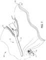
- FIG. 1depicts a perspective view of an exemplary articulating surgical stapling instrument
- FIG. 2depicts a side view of the instrument of FIG. 1 ;
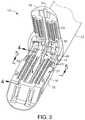
- FIG. 3depicts a perspective view of an opened end effector of the instrument of FIG. 1 ;
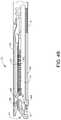
- FIG. 4Adepicts a side cross-sectional view of the end effector of FIG. 3 , taken along line 4 - 4 of FIG. 3 , with the firing beam in a proximal position;
- FIG. 4Bdepicts a side cross-sectional view of the end effector of FIG. 3 , taken along line 4 - 4 of FIG. 3 , with the firing beam in a distal position;
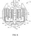
- FIG. 5depicts an end cross-sectional view of the end effector of FIG. 3 , taken along line 5 - 5 of FIG. 3 ;
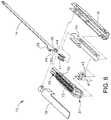
- FIG. 6depicts an exploded perspective view of the end effector of FIG. 3 ;
- FIG. 7depicts a perspective view of the end effector of FIG. 3 , positioned at tissue and having been actuated once in the tissue;
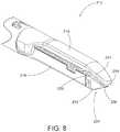
- FIG. 8depicts a perspective view of an alternative version of an end effector with an angled anvil and an angled cartridge
- FIG. 9depicts an enlarged, side view of the end effector of FIG. 8 ;
- FIG. 10depicts an enlarged top view of the end effector of FIG. 8 ;
- FIG. 11depicts an enlarged exploded perspective view of a distal portion of an alternative version of an end effector, with a curved anvil tip and cartridge nose having cooperating features;
- FIG. 12depicts a partial perspective view of a distal portion of another exemplary anvil for use with the end effector of FIG. 11 and similar to the anvil of FIG. 11 , but having an alternate underside surface and shown with a portion of the anvil tip in phantom to reveal the connection between the anvil tip and a body of the anvil;
- FIG. 13depicts an enlarged side view of a distal portion of an alternative version of an end effector, with a curved anvil tip and cartridge nose having cooperating features, and shown with the anvil in partial cross section to reveal the connection between the anvil tip and a body of the anvil;
- FIG. 14depicts an enlarged side view of a distal portion of an alternative version of an end effector, with a curved anvil tip and cartridge nose having cooperating features, and shown with a portion of the anvil tip and cartridge nose in cross section;
- FIG. 15depicts an enlarged side view of a distal portion of an alternative version of an end effector, with a curved anvil tip and cartridge nose having cooperating features, and shown with the anvil in partial cross section to reveal the connection between the anvil tip and a body of the anvil;
- FIG. 16depicts an enlarged side view of a distal portion of an alternative version of an end effector, with a curved anvil tip and cartridge nose having cooperating features, and shown with a portion of the anvil tip and cartridge nose in cross section;
- FIG. 17depicts a partial perspective view of the cartridge nose of FIG. 16 ;
- FIG. 18depicts a partial perspective view of a distal portion of an alternative version of a cartridge for use in an end effector, showing a plurality of gripping features along an angled surface of the cartridge nose and a plurality of gripping features along a deck of the cartridge;
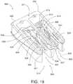
- FIG. 19depicts a perspective view of an exemplary tip replacement cartridge for use with end effectors having detachable anvil tips and cartridges with cooperating features;
- FIG. 20depicts a first side elevational view in a series of views showing installation of a new anvil tip and cartridge using the tip replacement cartridge of FIG. 19 ;
- FIG. 21depicts a second side elevational view in a series of views showing installation of a new anvil tip and cartridge using the tip replacement cartridge of FIG. 19 ;
- FIG. 22depicts a third side elevational view in a series of views showing installation of a new anvil tip and cartridge using the tip replacement cartridge of FIG. 19 .
- FIGS. 1-7depict an exemplary surgical stapling and severing instrument ( 10 ) that is sized for insertion, in a nonarticulated state as depicted in FIG. 1 , through a trocar cannula to a surgical site in a patient for performing a surgical procedure.
- a trocarmay be inserted in a patient's abdomen, between two of the patient's ribs, or elsewhere.
- instrument ( 10 )is used without a trocar.
- instrument ( 10 )may be inserted directly through a thoracotomy or other type of incision.
- Instrument ( 10 ) of the present exampleincludes a handle portion ( 20 ) connected to a shaft ( 22 ).
- Shaft ( 22 )distally terminates in an articulation joint ( 11 ), which is further coupled with an end effector ( 12 ).
- end effector12
- proximal and distalare used herein with reference to a clinician gripping handle portion ( 20 ) of instrument ( 10 ).
- end effector ( 12 )is distal with respect to the more proximal handle portion ( 20 ).
- spatial termssuch as “vertical” and “horizontal” are used herein with respect to the drawings. However, surgical instruments are used in many orientations and positions, and these terms are not intended to be limiting and absolute.
- shaft ( 22 )is constructed in accordance with at least some of the teachings of U.S. Pub. No. 2014/0239038, entitled “Surgical Instrument with Multi-Diameter Shaft,” published Aug. 28, 2014, issued as U.S. Pat. No. 9,795,379 on Oct. 24, 2017, the disclosure of which is incorporated by reference herein.
- shaft ( 22 )may be detachable from handle portion ( 20 ) in accordance with at least some of the teachings of U.S. Pub. No. 2015/0272575, entitled “Surgical Instrument Comprising a Sensor System,” published Oct. 1, 2015, issued as U.S. Pat. No. 9,913,642 on Mar. 13, 2018, the disclosure of which is incorporated by reference herein.
- shaft ( 22 )is not detachable from handle portion ( 20 ).
- Other suitable configurations for shaft ( 22 )will be apparent to those of ordinary skill in the art in view of the teachings herein.
- articulation joint ( 11 )may be remotely articulated, as depicted in phantom in FIG. 1 , by an articulation control ( 13 ), such that end effector ( 12 ) may be deflected from the longitudinal axis (LA) of shaft ( 22 ) at a desired angle (a). End effector ( 12 ) may thereby reach behind an organ or approach tissue from a desired angle or for other reasons.
- articulation joint ( 11 )enables deflection of end effector ( 12 ) along a single plane.
- articulation joint ( 11 )enables deflection of end effector along more than one plane.
- Articulation joint ( 11 ) and articulation control ( 13 )may be configured in accordance with the teachings of any of the numerous references that are cited herein.
- articulation joint ( 11 ) and/or articulation control ( 13 )may have any other suitable configuration.
- articulation control ( 13 )may instead be configured as a knob that rotates about an axis that is perpendicular to the longitudinal axis (LA) of shaft ( 22 ).
- articulation joint ( 11 ) and/or articulation control ( 13 )are/is constructed and operable in accordance with at least some of the teachings of U.S. Pat. No. 9,186,142, entitled “Surgical Instrument End Effector Articulation Drive with Pinion and Opposing Racks,” issued on Nov. 17, 2015, the disclosure of which is incorporated by reference herein.
- Articulation joint ( 11 )may also be constructed and operable in accordance with at least some of the teachings of U.S. Pub. No. 2014/0239038, entitled “Surgical Instrument with Multi-Diameter Shaft,” published Aug. 28, 2014, issued as U.S. Pat. No. 9,795,379 on Oct. 24, 2017, the disclosure of which is incorporated by reference herein.
- Other suitable forms that articulation joint ( 11 ) and articulation control ( 13 ) may takewill be apparent to those of ordinary skill in the art in view of the teachings herein.
- End effector ( 12 ) of the present exampleincludes a lower jaw ( 16 ) and a pivotable anvil ( 18 ).
- lower jaw ( 16 )is constructed in accordance with at least some of the teachings of U.S. Pub. No. 2014/0239044, entitled “Installation Features for Surgical Instrument End Effector Cartridge,” published on Aug. 28, 2014, issued as U.S. Pat. No. 9,808,248 on Nov. 7, 2017, the disclosure of which is incorporated by reference herein.
- Anvil ( 18 )may be constructed in accordance with at least some of the teachings of U.S. Pub. No. 2014/0239042, entitled “Integrated Tissue Positioning and Jaw Alignment Features for Surgical Stapler,” published on Aug.
- Handle portion ( 20 )includes a pistol grip ( 24 ) and a closure trigger ( 26 ).
- Closure trigger ( 26 )is pivotable toward pistol grip ( 24 ) to cause clamping, or closing, of the anvil ( 18 ) toward lower jaw ( 16 ) of end effector ( 12 ).
- Such closing of anvil ( 18 )is provided through a closure tube ( 32 ) and a closure ring ( 33 ), which both longitudinally translate relative to handle portion ( 20 ) in response to pivoting of closure trigger ( 26 ) relative to pistol grip ( 24 ).
- Closure tube ( 32 )extends along the length of shaft ( 22 ); and closure ring ( 33 ) is positioned distal to articulation joint ( 11 ). Articulation joint ( 11 ) is operable to communicate/transmit longitudinal movement from closure tube ( 32 ) to closure ring ( 33 ).
- Handle portion ( 20 )also includes a firing trigger ( 28 ).
- An elongate member(not shown) longitudinally extends through shaft ( 22 ) and communicates a longitudinal firing motion from handle portion ( 20 ) to a firing beam ( 14 ) in response to actuation of firing trigger ( 28 ).
- This distal translation of firing beam ( 14 )causes the stapling and severing of clamped tissue in end effector ( 12 ), as will be described in greater detail below.
- triggers ( 26 , 28 )may be released to release the tissue from end effector ( 12 ).
- FIGS. 3-6depict end effector ( 12 ) employing an E-beam form of firing beam ( 14 ) to perform a number of functions.
- Firing beam ( 14 )may take any other suitable form, including but not limited to non-E-beam forms.
- firing beam ( 14 )includes a transversely oriented upper pin ( 38 ), a firing beam cap ( 44 ), a transversely oriented middle pin ( 46 ), and a distally presented cutting edge ( 48 ).
- Upper pin ( 38 )is positioned and translatable within a longitudinal anvil slot ( 42 ) of anvil ( 18 ).
- Firing beam cap ( 44 )slidably engages a lower surface of lower jaw ( 16 ) by having firing beam ( 14 ) extend through lower jaw slot ( 45 ) (shown in FIG. 4B ) that is formed through lower jaw ( 16 ).
- Middle pin ( 46 )slidingly engages a top surface of lower jaw ( 16 ), cooperating with firing beam cap ( 44 ). Thereby, firing beam ( 14 ) affirmatively spaces end effector ( 12 ) during firing.
- firing beam ( 14 )may lack upper pin ( 38 ), middle pin ( 46 ) and/or firing beam cap ( 44 ). Some such versions of instrument ( 10 ) may simply rely on closure ring ( 33 ) or some other feature to pivot anvil ( 18 ) to a closed position and hold anvil ( 18 ) in the closed position while firing beam ( 14 ) advances to the distal position.
- firing beam ( 14 ) and/or associated lockout featuresmay be constructed and operable in accordance with at least some of the teachings of U.S. Pub. No. 2014/0239041, entitled “Lockout Feature for Movable Cutting Member of Surgical Instrument,” published on Aug. 28, 2014, issued as U.S. Pat. No. 9,717,497 on Aug. 1, 2017, the disclosure of which is incorporated by reference herein.
- Other suitable forms that firing beam ( 14 ) may takewill be apparent to those of ordinary skill in the art in view of the teachings herein.
- FIG. 3shows firing beam ( 14 ) of the present example proximally positioned and anvil ( 18 ) pivoted to an open position, allowing an unspent staple cartridge ( 37 ) to be removably installed into a channel of lower jaw ( 16 ).
- staple cartridge ( 37 ) of this exampleincludes a cartridge body ( 70 ), which presents an upper deck ( 72 ) and is coupled with a lower cartridge tray ( 74 ).
- a vertical slot ( 49 )is formed through part of staple cartridge ( 37 ).
- FIG. 3shows firing beam ( 14 ) of the present example proximally positioned and anvil ( 18 ) pivoted to an open position, allowing an unspent staple cartridge ( 37 ) to be removably installed into a channel of lower jaw ( 16 ).
- staple cartridge ( 37 ) of this exampleincludes a cartridge body ( 70 ), which presents an upper deck ( 72 ) and is coupled with a lower cartridge tray ( 74 ).
- a vertical slot ( 49 )is formed through part of staple cartridge
- three rows of staple apertures ( 51 )are formed through upper deck ( 72 ) on one side of vertical slot ( 49 ), with another set of three rows of staple apertures ( 51 ) being formed through upper deck ( 72 ) on the other side of vertical slot ( 49 ).
- any other suitable number of staple rowse.g., two rows, four rows, any other number
- a wedge sled ( 41 ) and a plurality of staple drivers ( 43 )are captured between cartridge body ( 70 ) and tray ( 74 ), with wedge sled ( 41 ) being located proximal to staple drivers ( 43 ).
- Wedge sled ( 41 )is movable longitudinally within staple cartridge ( 37 ); while staple drivers ( 43 ) are movable vertically within staple cartridge ( 37 ). Staples ( 47 ) are also positioned within cartridge body ( 70 ), above corresponding staple drivers ( 43 ). In particular, each staple ( 47 ) is driven vertically within cartridge body ( 70 ) by a staple driver ( 43 ) to drive staple ( 47 ) out through an associated staple aperture ( 51 ). As best seen in FIGS. 4A-4B and 6 , wedge sled ( 41 ) presents inclined cam surfaces that urge staple drivers ( 43 ) upwardly as wedge sled ( 41 ) is driven distally through staple cartridge ( 37 ).
- staple cartridge ( 37 )is constructed and operable in accordance with at least some of the teachings of U.S. Pub. No. 2014/0239042, entitled “Integrated Tissue Positioning and Jaw Alignment Features for Surgical Stapler,” published on Aug. 28, 2014, issued as U.S. Pat. No. 9,517,065 on Dec. 13, 2016, the disclosure of which is incorporated by reference herein.
- staple cartridge ( 37 )may be constructed and operable in accordance with at least some of the teachings of U.S. Pub. No. 2014/0239044, entitled “Installation Features for Surgical Instrument End Effector Cartridge,” published on Aug. 28, 2014, issued as U.S. Pat. No. 9,808,248 on Nov. 7, 2017, the disclosure of which is incorporated by reference herein.
- Other suitable forms that staple cartridge ( 37 ) may takewill be apparent to those of ordinary skill in the art in view of the teachings herein.
- firing beam ( 14 )is then advanced in engagement with anvil ( 18 ) by having upper pin ( 38 ) enter longitudinal anvil slot ( 42 ).
- a pusher block ( 80 )(shown in FIG. 5 ) is located at the distal end of firing beam ( 14 ), and is configured to engage wedge sled ( 41 ) such that wedge sled ( 41 ) is pushed distally by pusher block ( 80 ) as firing beam ( 14 ) is advanced distally through staple cartridge ( 37 ) when firing trigger ( 28 ) is actuated.
- middle pin ( 46 ) and pusher block ( 80 )together actuate staple cartridge ( 37 ) by entering into vertical slot ( 49 ) within staple cartridge ( 37 ), driving wedge sled ( 41 ) into upward camming contact with staple drivers ( 43 ) that in turn drive staples ( 47 ) out through staple apertures ( 51 ) and into forming contact with staple forming pockets ( 53 ) (shown in FIG. 3 ) on the inner surface of anvil ( 18 ).
- FIG. 4A-4Bmiddle pin ( 46 ) and pusher block ( 80 ) together actuate staple cartridge ( 37 ) by entering into vertical slot ( 49 ) within staple cartridge ( 37 ), driving wedge sled ( 41 ) into upward camming contact with staple drivers ( 43 ) that in turn drive staples ( 47 ) out through staple apertures ( 51 ) and into forming contact with staple forming pockets ( 53 ) (shown in FIG. 3 ) on the inner surface of anvil ( 18 ).
- FIG. 4Bdepicts firing beam ( 14 ) fully distally translated after completing severing and stapling of tissue. It should be understood that staple forming pockets ( 53 ) are intentionally omitted from the view in FIGS. 4A-4B ; but staple forming pockets ( 53 ) are shown in FIG. 3 . It should also be understood that anvil ( 18 ) is intentionally omitted from the view in FIG. 5 .
- FIG. 7shows end effector ( 12 ) having been actuated through a single stroke through tissue ( 90 ).
- cutting edge ( 48 )(obscured in FIG. 7 ) has cut through tissue ( 90 ), while staple drivers ( 43 ) have driven three alternating rows of staples ( 47 ) through the tissue ( 90 ) on each side of the cut line produced by cutting edge ( 48 ).
- Staples ( 47 )are all oriented substantially parallel to the cut line in this example, though it should be understood that staples ( 47 ) may be positioned at any suitable orientations.
- end effector ( 12 )is withdrawn from the trocar after the first stroke is complete, spent staple cartridge ( 37 ) is replaced with a new staple cartridge, and end effector ( 12 ) is then again inserted through the trocar to reach the stapling site for further cutting and stapling. This process may be repeated until the desired amount of cuts and staples ( 47 ) have been provided.
- Anvil ( 18 )may need to be closed to facilitate insertion and withdrawal through the trocar; and anvil ( 18 ) may need to be opened to facilitate replacement of staple cartridge ( 37 ).
- cutting edge ( 48 )may sever tissue substantially contemporaneously with staples ( 47 ) being driven through tissue during each actuation stroke.
- cutting edge ( 48 )just slightly lags behind driving of staples ( 47 ), such that a staple ( 47 ) is driven through the tissue just before cutting edge ( 48 ) passes through the same region of tissue, though it should be understood that this order may be reversed or that cutting edge ( 48 ) may be directly synchronized with adjacent staples. While FIG.
- end effector ( 12 )being actuated in two layers ( 92 , 94 ) of tissue ( 90 )
- end effector ( 12 )may be actuated through a single layer of tissue ( 90 ) or more than two layers ( 92 , 94 ) of tissue.
- the formation and positioning of staples ( 47 ) adjacent to the cut line produced by cutting edge ( 48 )may substantially seal the tissue at the cut line, thereby reducing or preventing bleeding and/or leaking of other bodily fluids at the cut line.
- FIG. 7shows end effector ( 12 ) being actuated in two substantially flat, apposed planar layers ( 92 , 94 ) of tissue, it should be understood that end effector ( 12 ) may also be actuated across a tubular structure such as a blood vessel, a section of the gastrointestinal tract, etc. FIG. 7 should therefore not be viewed as demonstrating any limitation on the contemplated uses for end effector ( 12 ).
- instrument ( 10 )may be used will be apparent to those of ordinary skill in the art in view of the teachings herein.
- instrument ( 10 )provides motorized control of firing beam ( 14 ).
- Exemplary components that may be used to provide motorized control of firing beam ( 14 )are shown and described in US. Pub. No. 2014/0239043, entitled “Distal Tip Features for End Effector of Surgical Instrument,” published on Aug. 28, 2014, issued as U.S. Pat. No. 9,622,746 on Apr. 18, 2017, the disclosure of which is incorporated by reference herein.
- at least part of the motorized controlmay be configured in accordance with at least some of the teachings of U.S. Pat. No. 8,210,411, entitled “Motor-Driven Surgical Instrument,” issued Jul. 3, 2012, the disclosure of which is incorporated by reference herein.
- the features operable to drive firing beam ( 14 )may be configured in accordance with at least some of the teachings of U.S. Pub. No. 2012/0239012, issued as U.S. Pat. No. 8,453,914 on Jun. 4, 2013, the disclosure of which is incorporated by reference herein; and/or in accordance with at least some of the teachings of U.S. Pub. No. 2012/0239012, issued as U.S. Pat. No. 8,453,914 on Jun. 4, 2013, the disclosure of which is also incorporated by reference herein.
- Other suitable components, features, and configurations for providing motorization of firing beam ( 14 )will be apparent to those of ordinary skill in the art in view of the teachings herein.
- firing beam ( 14 )may be actuated in accordance with at least some of the teachings of any other patent/publication reference cited herein.
- Instrument ( 10 )may also include a lockout switch and lockout indicator as shown and described in US. Pub. No. 2014/0239043, entitled “Distal Tip Features for End Effector of Surgical Instrument,” published on Aug. 28, 2014, issued as U.S. Pat. No. 9,622,746 on Apr. 18, 2017, the disclosure of which is incorporated by reference herein. Additionally, a lockout switch and/or lockout indication and associated components/functionality may be configured in accordance with at least some of the teachings of U.S. Pat. No. 7,644,848, entitled “Electronic Lockouts and Surgical Instrument Including Same,” issued Jan. 12, 2010, the disclosure of which is incorporated by reference herein.
- Instrument ( 10 )also include a manual return switch ( 116 ) configured to act as a “bailout” feature, enabling the operator to quickly begin retracting firing beam ( 14 ) proximally during a firing stroke.
- manual return switch ( 116 )may be manually actuated when firing beam ( 14 ) has only been partially advanced distally.
- Manual return switch ( 116 )may provide further functionality in accordance with at least some of the teachings of U.S. Pub. No. 2014/0239043, entitled “Distal Tip Features for End Effector of Surgical Instrument,” published on Aug. 28, 2014, issued as U.S. Pat. No. 9,622,746 on Apr. 18, 2017, the disclosure of which is incorporated by reference herein.
- anvil ( 18 )pivots about an axis that is defined by a pin (or similar feature) that slides along an elongate slot or channel as anvil ( 18 ) moves toward lower jaw ( 16 ). In such versions, the pivot axis translates along the path defined by the slot or channel while anvil ( 18 ) simultaneously pivots about that axis.
- pivot axismay slide along the slot/channel first, with anvil ( 18 ) then pivoting about the pivot axis after the pivot axis has slid a certain distance along the slot/channel.
- sliding/translating pivotal movementis encompassed within terms such as “pivot,” “pivots,” “pivotal,” “pivotable,” “pivoting,” and the like.
- some versionsmay provide pivotal movement of anvil ( 18 ) about an axis that remains fixed and does not translate within a slot or channel, etc.
- instrument ( 10 )may be configured and operable in accordance with any of the teachings of U.S. Pat. Nos. 4,805,823; 5,415,334; 5,465,895; 5,597,107; 5,632,432; 5,673,840; 5,704,534; 5,814,055; 6,978,921; 7,000,818; 7,143,923; 7,303,108; 7,367,485; 7,380,695; 7,380,696; 7,404,508; 7,434,715; 7,721,930; U.S. Pub. No. 2010/0264193, issued as U.S. Pat. No. 8,408,439 on Apr. 2, 2013; and/or 2012/0239012, issued as U.S.
- end effector ( 12 )it may be desirable to provide the user with better visualization of end effector ( 12 ).
- the usermay rotate shaft ( 22 ) of instrument ( 10 ) during the procedure.
- end effector ( 12 )also rotates.
- end effector ( 12 )could be rotated such that when the user views end effector ( 12 ), anvil ( 18 ) is visible by the user. It may be desirable to provide visibility of the surgical site for the user beyond what is possible in instrument ( 10 ) of FIG. 1 . For instance, in the case of some surgical procedures where fluid carrying vessels are transected and stapled, it may be desirable to have visual confirmation that anvil ( 18 ) and lower jaw ( 16 ) completely cover the vessel to be cut, such that the vessel may be fully cut and stapled in one single actuation. In other words, the user may wish to avoid cutting and stapling only a portion of a vessel.
- Some means of visual monitoring and/or feedbackmay be desirable so that the user will know that end effector ( 12 ) has been positioned properly within the surgical site for anvil ( 18 ) and lower jaw ( 16 ) to fully clamp the vessel.
- One potential way of monitoring the surgical sitemay include improving visualization of the area adjacent to the distal tip of lower jaw ( 16 ) and anvil ( 18 ).
- end effector ( 12 )may be desirable, but also it may be desirable to construct end effector ( 12 ) such that the distal end of anvil ( 18 ) is configured to urge tissue (e.g., a large vessel) proximally into the space between anvil ( 18 ) and lower jaw ( 16 ) as anvil ( 18 ) closes toward lower jaw ( 16 ).
- tissuee.g., a large vessel
- FIG. 8depicts an exemplary end effector ( 212 ) comprising an anvil ( 218 ) and a lower jaw ( 216 ). It will be appreciated that end effector ( 212 ) may be used in place of end effector ( 12 ) of instrument ( 10 ). End effector ( 212 ) may be integrally formed with instrument ( 10 ) or in the alternative may be interchangeable with end effector ( 12 ) of instrument ( 10 ).
- Anvil ( 218 )is operable to pivot relative to lower jaw ( 216 ).
- Anvil ( 218 ) and lower jaw ( 216 )may clamp tissue ( 90 ) similarly to clamping performed by anvil ( 18 ) and lower jaw ( 16 ) shown in FIG. 1 .
- End effector ( 212 )further comprises a cartridge ( 237 ) operable to be placed in lower jaw ( 216 ) similarly to cartridge ( 37 ) shown in FIG. 3 .
- Anvil ( 218 ) as can be seen in FIGS. 8-10has an elongated shape where the distal portion of anvil ( 218 ) angles toward cartridge ( 237 ).
- the distal portion of anvil ( 218 )angles toward cartridge ( 237 ) such that the distal most tip ( 219 ) of anvil ( 218 ) extends distally longitudinally further than cartridge ( 237 ).
- distal tip ( 219 )may extend to a distance longitudinally equal to cartridge ( 237 ) or proximal relative to the distal most point on cartridge ( 237 ).
- anvil ( 218 )angles toward cartridge ( 237 ) through a gentle slope. As seen best in FIG.
- anvil ( 218 )includes sides ( 241 ) that taper as they approach the distal most tip ( 219 ) of anvil ( 218 ).
- anvil ( 218 )is shaped in FIG. 8 similarly to an inverted ski tip.
- the angled shape of anvil ( 218 )may provide easier insertion of end effector ( 212 ) into a surgical site.
- the gentle slope or inverted ski tip shape of anvil ( 218 )may provide an atraumatic tissue deflection surface as anvil ( 218 ) contacts or moves through tissue.
- Such atraumatic tissue deflectionmay include urging tissue (e.g., a large vessel) proximally into the space between anvil ( 218 ) and lower jaw ( 216 ) as anvil ( 218 ) closes toward lower jaw ( 216 ).
- tissuee.g., a large vessel
- the angled shape of anvil ( 218 )may also provide better maneuverability of end effector ( 212 ) and better visibility of the distal end of end effector ( 212 ) in relation to anatomical structures at the surgical site.
- Other suitable variations of anvil ( 218 )will be apparent to one of ordinary skill in the art in view of the teachings herein.
- Cartridge ( 237 )is operable to hold staples similar to staples ( 47 ) shown in FIG. 4A for driving into tissue.
- the distal end of cartridge ( 237 )has a triangular profile.
- the distal end of cartridge ( 237 )comprises an upper tapered surface ( 239 ) and a lower tapered surface ( 238 ).
- the distal end of cartridge ( 237 )comprises a tapered side surface ( 243 ) on each side.
- each tapered side surface ( 243 ) of cartridge ( 237 )generally aligns with the taper presented by sides ( 241 ) of anvil ( 218 ).
- side surfaces ( 243 ) of cartridge ( 237 )do not extend outwardly from longitudinal axis (LA) of end effector ( 212 ) past sides ( 241 ) of anvil ( 218 ).
- Upper tapered surface ( 239 ) and lower tapered surface ( 238 )lead to the distal most end of cartridge ( 237 ).
- Lower tapered surface ( 238 )defines a sight line ( 240 ) such that once end effector ( 212 ) is inserted into a surgical site, the user can see along sight line ( 240 ).
- Sight line ( 240 )extends along the edge of lower tapered surface ( 238 ).
- planar shape of lower tapered surface ( 238 )may be operable to allow the user to visualize and/or nearly visualize the distal tip ( 219 ) of anvil ( 218 ).
- sight line ( 240 )intersects longitudinal axis (LA), which extends longitudinally through end effector ( 212 ), to form a viewing angle ( ⁇ ).
- Viewing angle ( ⁇ )may establish the relative visibility that a user has regarding distal tip ( 219 ).
- the usercan see in front of distal tip ( 219 ) along any line of sight that passes through the intersection of sight line ( 240 ) and longitudinal axis (LA) within viewing angle ( ⁇ ).
- viewing angle ( ⁇ )defines an angle greater than 90 degrees.
- viewing angle ( ⁇ )defines an angle greater than 135 degrees.
- viewing angle ( ⁇ )Other suitable angles for viewing angle ( ⁇ ) will be apparent to one of ordinary skill in the art in view of the teachings herein.
- the usergenerally looks along sight line ( 240 ) or along some other line of sight within viewing angle ( ⁇ ), thus, the user has visibility along sight line as well as any area within viewing angle ( ⁇ ).
- the underside of distal tip ( 219 )is further slightly rounded to aid in the visibility of the intersection of longitudinal axis (LA) and sight line ( 240 ).
- tissue ( 90 )When tissue ( 90 ) is clamped between a closed cartridge ( 237 ) and anvil ( 218 ), the user can look along sight line ( 240 ) or elsewhere within viewing angle ( ⁇ ) to see, for instance, precisely where anvil ( 218 ) has clamped tissue ( 90 ). Furthermore, the user would be able to determine whether the tissue is completely clamped between anvil ( 218 ) and cartridge ( 237 ) such that tissue does not spill over the end of end effector ( 212 ). The user may be able to also visualize the quality of the clamp between anvil ( 218 ) and cartridge ( 237 ) against tissue ( 90 ).
- end effector ( 212 )may be rotated before, during, or after clamping tissue ( 90 ).
- the tapered shape of anvil ( 218 )may also provide more accessible viewing of distal tip ( 219 ) or substantially adjacent distal tip ( 219 ).
- the taper of anvil ( 218 ) along with lower tapered surface ( 238 ) of cartridge ( 237 )may further promote easy insertion of end effector ( 212 ) into tissue in an atraumatic manner.
- itmay be easier to fit end effector ( 212 ) through a trocar or other devices operable to introduce end effector ( 212 ) into a surgical site due to the tapered end of end effector ( 212 ).
- lower tapered surface ( 238 ) and the tapered shape of anvil ( 218 )may provide a lead-in, guiding the rest of end effector ( 212 ) into the trocar.
- visibility and maneuverabilitycan be enhanced by the tapered design for both sides ( 241 ) of anvil ( 218 ) and each side ( 243 ) of cartridge ( 237 ).
- end effector ( 212 ) and versions of instrument ( 10 ) incorporating end effector ( 212 )may be configured and operable in accordance with at least some of the teachings of U.S. Pat. No. 9,186,142, entitled “Surgical Instrument End Effector Articulation Drive with Pinion and Opposing Racks,” issued Nov. 17, 2015, the disclosure of which is incorporated by reference herein; U.S. Pub. No. 2014/0239041, entitled “Lockout Feature for Movable Cutting Member of Surgical Instrument,” published Aug. 28, 2014, issued as U.S. Pat. No. 9,717,497 on Aug. 1, 2017, the disclosure of which is incorporated by reference herein; U.S. Pat. No.
- instrument ( 10 )may be placed at the surgical site, actuated to cut and staple, then removed from the surgical site for installing a new cartridge ( 37 ), and then be placed back at the surgical site again for the next cut and staple along the same path in which the previous cutting and stapling cycle occurred. This process is repeated until the cut and staple procedure is complete. As can be seen in FIGS. 4A-4B and FIG.
- the distal end configuration of end effector ( 12 )provides a gap between the distal end of anvil ( 18 ) and the distal end of cartridge ( 37 ). This gap may facilitate marching by providing an atraumatic space for tissue to enter the distal end of end effector ( 12 ) at the beginning of each marching step.
- the distal end configuration of end effector ( 212 )is different from the distal end configuration of end effector ( 12 ), with the different configuration of end effector ( 212 ) providing different potential advantages.
- the distal end configuration of end effector ( 212 )may provide improved maneuverability and improved visibility of the relationship between the distal end of end effector ( 212 ) and adjacent anatomical structures.
- the distal end configuration of end effector ( 212 )may provide tissue-gathering effects by urging tissue proximally into the space between anvil ( 218 ) and lower jaw ( 216 ) as anvil ( 218 ) is closed toward lower jaw ( 216 ).
- end effector ( 212 )may not lend itself well to marching operations, as distal tip ( 219 ) may impart trauma to tissue that is not gathered into the space between anvil ( 218 ) and lower jaw ( 216 ) as anvil ( 218 ) is closed toward lower jaw ( 216 ).
- end effector ( 212 )may be best suited for cutting and stapling operations (e.g., vessel transection) where all of the tissue that is to be cut and stapled is gathered proximal to distal tip ( 219 ).
- an anvilhas a distal tip that is resiliently biased to assume a bent or angled configuration like distal tip ( 219 ); yet the resiliently biased distal tip is deflectable away from the lower jaw in response to a sufficient load on the distal tip.
- an anvil with an elastically deformable angled distal tip portioncan provide an additional level of maneuverability benefits in terms of navigating through tissue to a surgical site.
- the deformable distal tip portionmay deflect or deform to promote smooth and atraumatic movement of the end effector through tissue, particularly during marching operations.
- an anvil having a bias to an angled position when not in a loaded state or contacted by surrounding tissueenhanced visualization during tissue capture and cutting can be achieved compared to using end effectors with a straight or non-angled anvil.
- an anvil with a distal tip that is biased to an angled positionmay provide some degree of tissue gathering effects up until reaching a load point that would be associated with marching rather than being associated with simply gathering a relatively small tissue structure between the anvil and lower jaw.
- Some exemplary end effectors having curved anvil tips that are elastically deformableare described in U.S. patent application Ser. No. 15/435,573, entitled “Surgical Stapler with Elastically Deformable Tip,” filed on Feb. 17, 2017, published as U.S. Pub. No. 2018/0235609 on Aug. 23, 2018, the disclosure of which is incorporated by reference herein.
- One exemplary way to provide anvils for end effectors that provide better visualization and maneuverability characteristicsis to configure an anvil with a modular curved tip, that may also be elastically deformable.
- Some exemplary anvils having modular curved tips, and that may be elastically deformableare described in U.S. patent application Ser. No. 15/435,607 entitled “Surgical Stapler with Insertable Distal Anvil Tip,” filed on Feb. 17, 2017, issued as U.S. Pat. No. 10,729,434 on Aug. 4, 2020, and the disclosure of which is incorporated by reference herein.
- end effectorsthat incorporate modular releasable anvil tips where the tips may be elastically deformable
- enhanced tissue grippingcan be achieved using end effectors having anvil tips and cartridge noses with cooperating features.
- cooperating featuresmay provide a lock or tissue stop that prevents clamped tissue from moving out of the distal end of the end effector during a cutting and stapling action.
- cooperating featuresmay also act as a tactile feedback feature to signal to a user that they have completely clamped the tissue, vessel, or tubular structure by feeling the cooperating features engage or contact at the distal end.
- such cooperating featurescan similarly act as a feedback feature or structure to signal to a user that they are at the end of the tissue path, as evidenced by the cooperating features engaging or contacting at the distal end (as opposed to the respective cooperating features each contacting tissue). Additionally, as described further below, to ensure that the matching anvil tips and cartridges tips are used together, such anvil tips and cartridges with cooperating features can be provided as a kit with a loading and/or unloading cartridge or tool.
- FIG. 11depicts an exemplary end effector ( 312 ) comprising an anvil ( 318 ) and a lower jaw ( 316 ).
- end effector ( 312 )may be used in place of end effector ( 12 ) of instrument ( 10 ).
- End effector ( 312 )may be integrally formed with instrument ( 10 ) or in the alternative may be interchangeable with end effector ( 12 ) of instrument ( 10 ).
- Anvil ( 318 )is operable to pivot relative to lower jaw ( 316 ).
- Anvil ( 318 ) and lower jaw ( 316 )may clamp tissue ( 90 ) similarly to clamping performed by anvil ( 18 ) and lower jaw ( 16 ) shown in FIG. 1 .
- End effector ( 312 )further comprises a cartridge ( 337 ) that is operable to be placed in lower jaw ( 316 ) similarly to cartridge ( 37 ) shown in FIG. 3 .
- Anvil ( 318 )comprises an anvil body ( 320 ) and an anvil tip ( 319 ).
- Anvil ( 318 )has an elongated shape where anvil body ( 320 ) is straight and anvil tip ( 319 ) extends distally in an angled or curved manner toward cartridge ( 337 ).
- Anvil tip ( 319 )includes sides ( 322 ) that taper as they approach the distal-most part of anvil tip ( 319 ), although such a tapered configuration is not required in all versions.
- anvil ( 318 )is shaped in FIGS. 11 and 12 with the shape of anvil tip ( 319 ) being similar to an inverted ski tip.
- anvil tip ( 319 )may provide an atraumatic tissue deflection surface as anvil ( 318 ) contacts or moves through tissue.
- the angled shape of anvil tip ( 319 )may provide better maneuverability of end effector ( 312 ).
- Other suitable variations of anvil ( 318 )will be apparent to one of ordinary skill in the art in view of the teachings herein.
- angled and curvedshall be read as being synonymous with each other when referring to a distal end configuration of a component of an end effector.
- the term “curved” (and variations thereof)may include a relationship between two straight features that together define an angle, such that the term “curved” (and variations thereof) should not be read as requiring a component to necessarily extend along an arc.
- Anvil ( 318 )further comprises staple forming pockets ( 53 ) as described above; and longitudinal anvil slot ( 42 ) as also described above.
- anvil tip ( 319 )is configured as a modular releasable component that selectively connects with or attaches to anvil body ( 320 ).
- anvil tip ( 319 )comprises an insert or other structure that extends proximally and is configured to be received within a distal end of longitudinal slot ( 42 ).
- Anvil tip ( 319 )comprises a bottom surface ( 324 ) that faces cartridge ( 337 ) and that is configured to contact tissue ( 90 ) when end effector ( 312 ) is in a loaded state clamping tissue ( 90 ).
- anvil tip ( 319 )comprises one or more features ( 326 ) that are configured to also contact tissue ( 90 ) when end effector ( 312 ) is in a loaded state.
- one or more features ( 326 )comprise a pair of raised arcuate ribs that generally extend transversely across a width of anvil tip ( 319 ). In this manner, the raised arcuate ribs protrude or extend from bottom surface ( 324 ) toward cartridge ( 337 ).
- anvil tip ( 319 )comprises greater or fewer ribs.
- one or more features ( 326 )are positioned along or closer to a distal end of anvil tip ( 319 ) rather than along a proximal end of anvil tip ( 319 ). In some other versions, however, one or more features ( 326 ) can be located along a middle portion, proximal end, or other portions of bottom surface ( 324 ) of anvil tip ( 319 ).
- Anvil tip ( 319 )is comprised of an elastomeric material in the present example. With such a construction, in use during clamping tissue, anvil tip ( 319 ) may deflect or bend from a curved state to a straight or less curved state. By way of example only, tip ( 319 ) may be deflectable between about 20 degrees and about 70 degrees in a downward direction from a longitudinal axis toward cartridge; between about 0 degrees and about 90 degrees in an upward direction from a longitudinal axis toward cartridge ( 337 ). The degree of deflection may be influenced by the thickness and/or density of the tissue that is being compressed between anvil ( 318 ) and cartridge ( 337 ).
- anvil tip ( 319 )may deflect or bend from a curved state to a straight or less curved state in accordance with at least some of the teachings in U.S. patent application Ser. No. 15/435,573, entitled “Surgical Stapler with Elastically Deformable Tip,” filed on Feb. 17, 2017, published as U.S. Pat. No. 2018/0235609 on Aug. 23, 2018, the disclosure of which is incorporated by reference herein.
- anvil tip ( 319 )is operably configured for use in procedures where marching is used.
- one or more features ( 326 )are similarly formed of an elastomeric material such that they are also elastically deformable.
- one or more features ( 326 )are elastically deformable to a different extent than anvil tip ( 319 ) generally.
- one or more features ( 326 )can be elastically deformable to the same or to a greater extent compared to anvil tip ( 319 ) generally.
- various ways to modify and manipulate the degree or extent of elastic deformability of one or more features ( 326 ) and/or anvil tip ( 319 )generally will be apparent to those of ordinary skill in the art.
- anvil tip ( 319 ) and/or its one or more features ( 326 )are not required to be elastically deformable and thus may be rigid.
- Cartridge ( 337 )is operable to hold staples similar to staples ( 47 ) shown in FIG. 4A for driving into tissue.
- cartridge ( 337 )comprises a nose portion ( 344 ) at a distal end.
- Cartridge nose ( 344 )has a triangular profile.
- cartridge nose ( 344 )comprises an upper tapered surface ( 339 ), a bottom surface ( 340 ), and side surfaces ( 342 ).
- bottom surface ( 340 )is generally parallel with a longitudinal axis defined by cartridge ( 337 ). In some other examples, bottom surface ( 340 ) is angled toward the longitudinal axis defined by cartridge ( 337 ), similar to the configuration shown above with respect to cartridge ( 237 ).
- cartridge ( 337 )comprises one or more features ( 346 ) that are configured to also contact tissue ( 90 ) when end effector ( 312 ) is in a loaded state.
- one or more features ( 346 )comprise a pair of raised arcuate ribs that generally extend transversely across a width of cartridge ( 337 ). In this manner, the raised arcuate ribs protrude or extend from upper surface ( 339 ) toward anvil tip ( 319 ). While the present example shows three such ribs, in other versions nose portion ( 344 ) of cartridge ( 337 ) comprises greater or fewer ribs.
- one or more features ( 346 )are positioned along or closer to a middle and distal end of nose portion ( 344 ) rather than along a proximal end of nose portion ( 344 ). In some other versions, however, one or more features ( 346 ) can be located along a proximal end, or other portions of upper surface ( 339 ) of cartridge ( 337 ).
- cartridge ( 337 ) and one or more features ( 346 ) protruding from nose portion ( 344 )are rigid such that they do not elastically deform when end effector ( 312 ) is in a loaded state clamping tissue ( 90 ). Furthermore, when end effector ( 312 ) is closed and in a non-loaded state not clamping tissue, one or more features ( 346 ) of cartridge ( 337 ) are configured to complement one or more features ( 326 ) of anvil tip ( 319 ).
- one or more features ( 346 ) of cartridge ( 337 ) and one or more features ( 326 ) of anvil tip ( 319 )cooperate to form a nesting arrangement.
- one or more features ( 326 ) of anvil tip ( 319 )are positionable adjacent to one or more features ( 346 ) of cartridge ( 337 ).
- a distal-most rib of anvil tip ( 319 )is positioned adjacent to and proximal to a distal-most rib of cartridge ( 337 ).
- a distal-most rib of anvil tip ( 319 )is positioned adjacent to and distal to a distal-most rib of cartridge ( 337 ).
- end effector ( 312 )comprises the combination of elastically deformable anvil tip ( 319 ) having one or more features ( 326 ), combined with rigid cartridge nose ( 344 ) having one or more features ( 346 ). Furthermore, as described above the one or more features ( 326 ) cooperate with, or are complementary to, the one or more features ( 346 ). In other versions, one or more features ( 346 ) of cartridge nose ( 344 ) can be configured as elastically deformable while one or more features ( 326 ) of anvil tip ( 319 ) can be configured as rigid. Still yet in other versions, both of one or more features ( 326 , 346 ) can be elastically deformable, or both can be rigid.
- bottom surface ( 324 ) of anvil tip ( 319 ) and upper surface ( 339 ) of cartridge nose portion ( 344 )are generally parallel surfaces.
- This parallel orientationpromotes equal nesting of one or more features ( 326 ) of anvil ( 319 ) with one or more features ( 346 ) of nose portion ( 344 ).
- the most distal features ( 326 , 346 )will nest to the same extent or degree as the most proximal features ( 326 , 346 ).
- this parallel orientationprovides for a consistent gap between those portions of anvil bottom surface ( 324 ) and cartridge upper surface ( 339 ) not having the one or more features ( 326 , 346 ).
- other arrangements for the orientation of bottom surface ( 324 ) and upper surface ( 339 ), including non-parallel arrangementswill be apparent to those of ordinary skill in the art.
- FIG. 11is described as one or more features ( 326 ) of anvil tip ( 319 ) and one or more features ( 346 ) of cartridge nose ( 344 ) adopting a nesting arrangement, in some instances such an arrangement may be a contacting arrangement where one or more features ( 326 ) of anvil tip ( 319 ) contact with upper surface ( 339 ) of cartridge nose ( 344 ) when end effector ( 312 ) is closed and in an unloaded state and/or one or more features ( 346 ) of cartridge nose ( 344 ) contact with bottom surface ( 324 ) of anvil tip ( 319 ) when end effector ( 312 ) is closed and in an unloaded state.
- the gap between the flat regions of bottom surface ( 324 ) and upper surface ( 339 )generally equals the distance that the protruding ribs extend away from their respective bottom surface ( 324 ) and upper surface ( 339 ).
- Some other nesting arrangementsare non-contacting arrangements where, even when end effector ( 312 ) is closed and in an unloaded state where no tissue is within end effector ( 312 ), one or more features ( 326 ) of anvil tip ( 319 ) do not contact cartridge ( 337 ); and similarly one or more features ( 346 ) of cartridge nose ( 344 ) do not contact anvil tip ( 319 ).
- one or more features ( 326 , 346 )contact tissue in a manner that applies staggered concentrations of force to clamped tissue ( 90 ). These staggered concentrations of force coincide with the locations where one or more features ( 326 , 346 ) that protrude from respective anvil tip ( 319 ) and cartridge nose ( 344 ) contact tissue ( 90 ).
- the one or more features ( 326 , 346 )also provide a tissue stop or locking feature that prevents tissue ( 90 ) that is clamped between anvil ( 318 ) and cartridge ( 337 ) from spilling over the end of end effector ( 312 ).
- end effector ( 312 )may be rotated before, during, or after clamping tissue ( 90 ).
- the curved shape of anvil ( 318 )may also provide more accessible viewing of anvil tip ( 319 ) or regions substantially adjacent anvil tip ( 319 ).
- the curve of anvil ( 318 )may further promote easy insertion of end effector ( 312 ) into tissue in an atraumatic manner.
- itmay be easier to fit end effector ( 312 ) through a trocar or other devices operable to introduce end effector ( 312 ) into a surgical site due to the curve of anvil ( 318 ) of end effector ( 312 ).
- cartridge ( 337 )comprises vertical slot ( 349 ) having the same or similar structure and function as vertical slot ( 49 ) discussed above.
- Cartridge ( 337 )also comprises staple apertures ( 351 ) having the same or similar structure and function as staple apertures ( 51 ) discussed above.
- cartridge ( 337 )is generally flat along a staple deck ( 348 ) with staple apertures ( 351 ) being along the same plane defined by staple deck ( 348 ).
- cartridge ( 337 )comprises shelf ( 350 ), which is also flat but is slightly recessed relative to staple deck ( 348 ).
- cartridge ( 337 )may be modified similar to cartridge ( 37 ) above by having cartridge ( 337 ) include separate raised areas and recessed areas such that one row of staple apertures ( 51 ) may be higher or lower than another row of staple apertures ( 51 ).
- staple deck ( 348 ) of cartridge ( 337 )could be modified so that staple deck ( 348 ) defines more than one plane and staple apertures ( 351 ) are not all along the same plane, but instead are found of different planes that face anvil ( 318 ).
- FIG. 11illustrates anvil body ( 320 ) as having recessed areas ( 328 ) along an outer region of anvil body ( 320 ).
- anvil body ( 320 )has a raised area ( 330 ) along a center region of anvil body ( 320 ).
- anvil ( 317 )may comprise anvil body ( 321 ) having a flat area ( 332 ) along the portion of anvil body ( 321 ) having staple forming pockets ( 53 ).
- staple forming pockets ( 53 )may be co-planar, yet in other instances staple forming pockets ( 53 ) may be located along different planes defined by the undersurface of anvil body ( 320 ). It should be noted that the other features of anvils ( 317 , 318 ) are identical except for the underside surface configuration as described here. In view of the teachings herein, various modifications and other ways to configure anvils ( 317 , 318 ) will be apparent to those of ordinary skill in the art.
- FIG. 13illustrates another exemplary end effector ( 412 ) comprising anvil ( 418 ) and lower jaw ( 416 ).
- end effector ( 412 )may be used in place of end effector ( 12 ) of instrument ( 10 ).
- End effector ( 412 )may be integrally formed with instrument ( 10 ) or in the alternative may be interchangeable with end effector ( 12 ) of instrument ( 10 ).
- Anvil ( 418 )is operable to pivot relative to lower jaw ( 416 ).
- Anvil ( 418 ) and lower jaw ( 416 )may clamp tissue ( 90 ) similarly to clamping performed by anvil ( 18 ) and lower jaw ( 16 ) shown in FIG. 1 .
- End effector ( 412 )further comprises a cartridge ( 437 ) that is operable to be placed in lower jaw ( 416 ) similarly to cartridge ( 37 ) shown in FIG. 3 .
- Anvil ( 418 )is similar to anvil ( 318 ) described above.
- Anvil ( 418 )comprises an anvil body ( 420 ) and an anvil tip ( 419 ).
- Anvil ( 418 )has an elongated shape where anvil body ( 420 ) is straight and anvil tip ( 419 ) extends distally in an angled or curved manner toward cartridge ( 437 ).
- anvil tip ( 419 )is shaped similar to an inverted ski tip. This may provide easier insertion of end effector ( 412 ) into a surgical site.
- the gentle slope or inverted ski tip shape of anvil tip ( 419 )may provide an atraumatic tissue deflection surface as anvil ( 418 ) contacts or moves through tissue.
- anvil tip ( 419 )may provide better maneuverability of end effector ( 412 ).
- Other suitable variations of anvil ( 418 )will be apparent to one of ordinary skill in the art in view of the teachings herein.
- Anvil ( 418 )further comprises staple forming pockets (not shown) as described above, and a longitudinal anvil slot ( 42 ) as also described above.
- anvil tip ( 419 )is configured as a modular releasable component that selectively connects with or attaches to anvil body ( 420 ).
- anvil tip ( 419 )comprises a fastener ( 434 ) such as an insert, shim, or other structure that extends proximally and is configured to be received within a distal end of longitudinal slot ( 42 ).
- Anvil tip ( 419 )comprises a bottom surface ( 424 ) that faces cartridge ( 437 ) and that is configured to contact tissue ( 90 ) when end effector ( 412 ) is in a loaded state clamping tissue ( 90 ).
- anvil tip ( 419 )comprises one or more features ( 426 ) that are configured to also contact tissue ( 90 ) when end effector ( 412 ) is in a loaded state.
- one or more features ( 426 )comprise a pair of raised ribs that generally extend transversely across a width of anvil tip ( 419 ). In this manner, the raised ribs protrude or extend from bottom surface ( 424 ) toward cartridge ( 437 ).
- anvil tip ( 419 )comprises greater or fewer ribs.
- one or more features ( 426 )are positioned along or closer to a distal end of anvil tip ( 419 ) rather than along a proximal end of anvil tip ( 419 ).
- the pair of raised ribsare configured such that anvil tip ( 419 ) distally terminates at one of the pair of raised ribs.
- one of the one or more features ( 426 )is located at the distal end of anvil tip ( 419 ), with the other one of the one or more features ( 426 ) being proximal thereof as shown in FIG. 13 .
- one or more features ( 426 )can be located along a middle portion, proximal end, or other portions of bottom surface ( 424 ) of anvil tip ( 419 ).
- anvil tip ( 419 )comprises a steeper angle or greater amount of curvature compared to anvil tip ( 319 ).
- a longitudinal axis defined by anvil body ( 420 ), and a longitudinal axis defined by a distal portion of anvil tip ( 419 )intersect to form an angle of between about 110 degrees and about 125 degrees.
- the same angle with anvil tip ( 319 ) and body ( 320 )is greater as the angle of anvil tip ( 319 ) relative to anvil body ( 320 ) is more gradual.
- the same angle for anvil tip ( 319 ) and anvil body ( 320 ) in one versionis between about 135 degrees and about 160 degrees. Still with either anvil tip ( 319 , 419 ), these angles may be larger or smaller as those of ordinary skill in the art will understand in view of the teachings herein.
- Anvil tip ( 419 )is comprised of an elastomeric material in the present example. With such a construction, in use during clamping tissue anvil tip ( 419 ) may deflect or bend from a curved state to a straight or less curved state.
- tip ( 419 )may be deflectable between about 20 degrees and about 70 degrees in a downward direction from a longitudinal axis toward cartridge; between about 0 degrees and about 90 degrees in an upward direction from a longitudinal axis toward cartridge ( 437 ).
- the degree of deflectionmay be influenced by the thickness and/or density of the tissue that is being compressed between anvil ( 418 ) and cartridge ( 437 ).
- anvil tip ( 319 )may deflect or bend from a curved state to a straight or less curved state in accordance with at least some of the teachings in U.S. patent application Ser. No. 15/435,573, entitled “Surgical Stapler with Elastically Deformable Tip,” filed on Feb. 17, 2017, published as U.S. Pub. No. 2018/0235609 on Aug. 23, 2018, the disclosure of which is incorporated by reference herein.
- anvil tip ( 419 )is operably configured for use in procedures where marching is used.
- one or more features ( 426 )are similarly formed of an elastomeric material such that they are also elastically deformable.
- one or more features ( 426 )are elastically deformable to a different extent than anvil tip ( 419 ) generally.
- one or more features ( 426 )can be elastically deformable to the same or to a greater extent compared to anvil tip ( 419 ) generally.
- various ways to modify and manipulate the degree or extent of elastic deformability of one or more features ( 426 ) and/or anvil tip ( 419 )generally will be apparent to those of ordinary skill in the art.
- anvil tip ( 419 ) and/or its one or more features ( 426 )are not required to be elastically deformable and thus may be rigid.
- Cartridge ( 437 )is operable to hold staples similar to staples ( 47 ) shown in FIG. 4A for driving into tissue.
- cartridge ( 437 )comprises a nose portion ( 444 ) at a distal end.
- Cartridge nose ( 444 )has a triangular profile.
- cartridge nose ( 444 )comprises an upper tapered surface ( 439 ), a bottom surface ( 440 ), and side surfaces ( 442 ).
- bottom surface ( 440 )is generally parallel with a longitudinal axis defined by cartridge ( 437 ). In some other examples, bottom surface ( 440 ) is angled toward the longitudinal axis defined by cartridge ( 437 ), similar to the configuration shown above with respect to cartridge ( 237 ).
- cartridge ( 437 )comprises one or more features ( 446 ) that are configured to also contact tissue ( 90 ) when end effector ( 412 ) is in a loaded state.
- one or more features ( 446 )comprise a pair of raised ribs that generally extend transversely across a width of cartridge ( 437 ). In this manner, the raised ribs protrude or extend from upper surface ( 439 ) toward anvil tip ( 419 ). While the present example shows two such ribs, in other versions nose portion ( 444 ) of cartridge ( 437 ) comprises greater or fewer ribs.
- one or more features ( 446 )are positioned along or closer to a middle and distal end of nose portion ( 444 ) rather than along a proximal end of nose portion ( 444 ). In some other versions, however, one or more features ( 446 ) can be located along a proximal end, or other portions of, upper surface ( 439 ) of cartridge ( 437 ).
- cartridge ( 437 ) and one or more features ( 446 ) protruding from nose portion ( 444 )are rigid such that they do not elastically deform when end effector ( 412 ) is in a loaded state clamping tissue ( 90 ). Furthermore, when end effector ( 412 ) is closed and in a non-loaded state not clamping tissue, one or more features ( 446 ) of cartridge ( 437 ) are configured to complement one or more features ( 426 ) of anvil tip ( 419 ).
- one or more features ( 446 ) of cartridge ( 437 ) and one or more features ( 426 ) of anvil tip ( 419 )cooperate to form a nesting arrangement.
- one or more features ( 426 ) of anvil tip ( 419 )are positionable adjacent to one or more features ( 446 ) of cartridge ( 437 ).
- a distal-most rib of anvil tip ( 419 )is positioned adjacent to and distal to a distal-most rib of cartridge ( 437 ).
- a distal-most rib of anvil tip ( 419 )can be positioned adjacent to and proximal to a distal-most rib of cartridge ( 437 ), similar to end effector ( 312 ) described above.
- end effector ( 412 )comprises the combination of elastically deformable anvil tip ( 419 ) having one or more features ( 426 ), combined with rigid cartridge nose ( 444 ) having one or more features ( 446 ). Furthermore, as described above the one or more features ( 426 ) cooperate with, or are complementary to, the one or more features ( 446 ). In other versions, one or more features ( 446 ) of cartridge nose ( 444 ) can be configured as elastically deformable while one or more features ( 426 ) of anvil tip ( 419 ) can be configured as rigid. Still yet in other versions, both of one or more features ( 426 , 446 ) can be elastically deformable, or both can be rigid.
- bottom surface ( 424 ) of anvil tip ( 419 ) and upper surface ( 439 ) of cartridge nose portion ( 444 )are generally parallel surfaces. This parallel orientation promotes equal nesting of one or more features ( 426 ) of anvil ( 419 ) with one or more features ( 446 ) of nose portion ( 444 ). For instance, in the present example, the most distal features ( 426 , 446 ) will nest to the same extent or degree as the most proximal features ( 326 , 446 ). In view of the teachings herein, other arrangements for the orientation of bottom surface ( 424 ) and upper surface ( 439 ), including non-parallel arrangements, will be apparent to those of ordinary skill in the art.
- Anvil tip ( 419 )has a steep angle as described above.
- anvil tip ( 419 )comprises a rear surface ( 436 ) that extends along the distal portion of anvil tip ( 419 ) that defines the longitudinal axis of anvil tip ( 419 ) as described above.
- rear surface ( 436 )is not parallel with upper surface ( 439 ) of cartridge ( 437 ).
- end effector ( 412 )comprises a void space ( 414 ) between anvil tip ( 419 ) and upper surface ( 439 ) of cartridge ( 437 ).
- void space ( 414 )has a triangular profile.
- FIG. 13is described as one or more features ( 426 ) of anvil tip ( 419 ) and one or more features ( 446 ) of cartridge nose ( 444 ) adopting a nesting arrangement, in some instances such an arrangement may be a contacting arrangement where one or more features ( 426 ) of anvil tip ( 419 ) contact with upper surface ( 439 ) of cartridge nose ( 444 ) when end effector ( 412 ) is closed and in an unloaded state and/or one or more features ( 446 ) of cartridge nose ( 444 ) contact with bottom surface ( 424 ) of anvil tip ( 419 ) when end effector ( 412 ) is closed and in an unloaded state.
- the gap between the flat regions of bottom surface ( 424 ) and upper surface ( 439 )generally equals the distance the protruding ribs extend away from their respective bottom surface ( 424 ) and upper surface ( 439 ).
- Some other nesting arrangementsare non-contacting arrangements where, even when end effector ( 412 ) is closed and in an unloaded state where no tissue is within end effector ( 412 ), one or more features ( 426 ) of anvil tip ( 419 ) do not contact cartridge ( 437 ); and similarly one or more features ( 446 ) of cartridge nose ( 444 ) do not contact anvil tip ( 419 ).
- one or more features ( 426 , 446 )contact tissue in a manner that applies staggered concentrations of force to clamped tissue ( 90 ). These staggered concentrations of force coincide with the locations where one or more features ( 426 , 446 ) that protrude from respective anvil tip ( 419 ) and cartridge nose ( 444 ) contact tissue ( 90 ).
- the one or more features ( 426 , 446 )also provide a tissue stop or locking feature that prevents tissue ( 90 ) that is clamped between anvil ( 418 ) and cartridge ( 437 ) from spilling over the end of end effector ( 412 ).
- end effector ( 412 )may be rotated before, during, or after clamping tissue ( 90 ).
- the curved shape of anvil ( 418 )may also provide more accessible viewing of anvil tip ( 419 ) or regions substantially adjacent anvil tip ( 419 ).
- the curve of anvil ( 418 )may further promote easy insertion of end effector ( 412 ) into tissue in an atraumatic manner.
- itmay be easier to fit end effector ( 412 ) through a trocar or other devices operable to introduce end effector ( 412 ) into a surgical site due to the curve of anvil ( 418 ) of end effector ( 412 ).
- cartridge ( 437 )comprises vertical slot (not shown) having the same or similar structure and function as vertical slot ( 49 ) discussed above.
- Cartridge ( 437 )also comprises staple apertures (not shown) having the same or similar structure and function as staple apertures ( 51 ) discussed above.
- cartridge ( 437 )comprises a stepped staple deck ( 448 ).
- Stepped staple deck ( 448 )includes regions or areas of staple deck ( 448 ) that define different planes of staple deck ( 448 ) such that staple apertures along staple deck ( 448 ) may be located along different planes that face anvil ( 418 ).
- cartridge ( 437 )may be fitted with staples of varying lengths. For instance an outer row of staples may be longer compared to the staples used closer to a centerline of cartridge ( 437 ). This may promote better stapling of tissue having a thickness that varies across the width of end effector ( 412 ).
- cartridge ( 437 )comprises stepped staple deck ( 448 ) that defines three separate planes.
- a first planeis defined by an outer region ( 452 ) of staple deck ( 448 ).
- the first plane and outer region ( 452 )are common to both sides of staple deck ( 448 ) such that the outer region on one side of staple deck ( 448 ) is co-planar with the outer region on the other side of staple deck ( 448 ).
- a second planeis defined by a middle region ( 454 ) of staple deck ( 448 ).
- the second plane and middle region ( 454 )are common to both sides of staple deck ( 448 ) such that the middle region on one side of staple deck ( 448 ) is co-planar with the middle region on the other side of staple deck ( 448 ).
- a third planeis defined by an inner region ( 456 ) of staple deck ( 448 ).
- the third plane and inner region ( 456 )are common to both sides of staple deck ( 448 ) such that the inner region on one side of staple deck ( 448 ) is co-planar with the inner region on the other side of staple deck ( 448 ).
- cartridge ( 437 )may be modified similar to cartridge ( 337 ) above by having cartridge ( 437 ) include a staple deck that defines a single plane such that all staple apertures are located along the same plane facing anvil ( 418 ).
- anvil body ( 420 )may have recessed areas along an outer region of anvil body ( 420 ) as described above with respect to anvil body ( 320 ).
- anvil ( 418 )may comprise anvil body ( 420 ) having a flat area along the portion of anvil body ( 420 ) having staple forming pockets as described above with respect to anvil body ( 321 ) of FIG. 12 .
- various modifications and other ways to configure anvil ( 418 )will be apparent to those of ordinary skill in the art.
- anvil body ( 420 )may have a complementary stepped underside surface to maintain a consistent gap between anvil ( 418 ) and cartridge ( 437 ) when end effector ( 412 ) is closed.
- anvil body ( 420 )may be stepped or not stepped such that a consistent gap is not required across the lateral width of anvil ( 418 ) and cartridge ( 437 ).
- end effector ( 412 )is configured such that nose ( 444 ) of cartridge ( 437 ) extends distal to anvil tip ( 419 ) when end effector ( 412 ) is closed in a non-loaded state.
- anvil tip ( 419 )may deflect when contacting or clamping tissue. In its deflected state, anvil tip ( 419 ) may extend distally such that anvil tip ( 419 ) aligns with the distal end of nose ( 444 ) of cartridge ( 437 ), or in some versions extends distally past the distal end of nose ( 444 ).
- FIG. 14illustrates another exemplary end effector ( 512 ) comprising anvil ( 518 ) and lower jaw ( 516 ). It will be appreciated that end effector ( 512 ) may be used in place of end effector ( 12 ) of instrument ( 10 ). End effector ( 512 ) may be integrally formed with instrument ( 10 ) or in the alternative may be interchangeable with end effector ( 12 ) of instrument ( 10 ). Anvil ( 518 ) is operable to pivot relative to lower jaw ( 516 ). Anvil ( 518 ) and lower jaw ( 516 ) may clamp tissue ( 90 ) similarly to clamping performed by anvil ( 18 ) and lower jaw ( 16 ) shown in FIG. 1 . End effector ( 512 ) further comprises a cartridge ( 537 ) that is operable to be placed in lower jaw ( 516 ) similarly to cartridge ( 37 ) shown in FIG. 3 .
- Anvil ( 518 )is similar to anvils ( 318 , 418 ) described above.
- Anvil ( 518 )comprises an anvil body ( 520 ) and an anvil tip ( 519 ).
- Anvil ( 518 )has an elongated shape where anvil body ( 520 ) is straight and anvil tip ( 519 ) extends distally in an angled or curved manner toward cartridge ( 537 ).
- anvil tip ( 519 )is shaped similar to an inverted ski tip. This may provide easier insertion of end effector ( 512 ) into a surgical site.
- anvil tip ( 519 )may provide an atraumatic tissue deflection surface as anvil ( 518 ) contacts or moves through tissue.
- the angled shape of anvil tip ( 519 )may provide better maneuverability of end effector ( 512 ).
- Other suitable variations of anvil ( 518 )will be apparent to one of ordinary skill in the art in view of the teachings herein.
- Anvil ( 518 )further comprises staple forming pockets (not shown) as described above, and a longitudinal anvil slot (not shown) as also described above.
- anvil tip ( 519 )is configured as a modular releasable component that selectively connects with or attaches to anvil body ( 520 ).
- anvil tip ( 519 )comprises a fastener (not shown) such as an insert, shim, or other structure that extends proximally and is configured to be received within a distal end of the longitudinal slot.
- Anvil tip ( 519 )comprises a bottom surface ( 524 ) that faces cartridge ( 537 ) and that is configured to contact tissue ( 90 ) when end effector ( 512 ) is in a loaded state clamping tissue ( 90 ).
- anvil tip ( 519 )comprises one or more features ( 526 ) that are configured to also contact tissue ( 90 ) when end effector ( 512 ) is in a loaded state.
- one or more features ( 526 )comprise a single raised rib that generally extends transversely across a width of anvil tip ( 519 ). In this manner, the raised rib protrudes or extends from bottom surface ( 524 ) toward cartridge ( 537 ).
- anvil tip ( 519 )comprises greater or fewer ribs.
- one or more features ( 526 )are positioned along a distal end of anvil tip ( 519 ) rather than along a more proximal portion of anvil tip ( 519 ).
- the ribis configured such that anvil tip ( 519 ) distally terminates at the rib.
- one or more features ( 526 )are not required to be at the distal end of anvil tip ( 519 ), and can instead or in addition be located along a more proximal portion of bottom surface ( 524 ) of anvil tip ( 519 ).
- anvil tip ( 519 )comprises a steeper angle or greater amount of curvature compared to anvil tip ( 319 ), but less than that compared to anvil tip ( 419 ).
- a longitudinal axis defined by anvil body ( 520 ), and a longitudinal axis defined by a distal portion of anvil tip ( 519 )intersect to form an angle of between about 130 degrees and about 150 degrees.
- the same angle with anvil tip ( 319 ) and body ( 320 )is greater as the angle of anvil tip ( 319 ) relative to anvil body ( 320 ) is more gradual.
- Anvil tip ( 519 )is comprised of an elastomeric material in the present example. With such a construction, in use during clamping tissue anvil tip ( 519 ) may deflect or bend from a curved state to a straight or less curved state.
- tip ( 519 )may be deflectable between about 20 degrees and about 70 degrees in a downward direction from a longitudinal axis toward cartridge; between about 0 degrees and about 90 degrees in an upward direction from a longitudinal axis toward cartridge ( 537 ).
- the degree of deflectionmay be influenced by the thickness and/or density of the tissue that is being compressed between anvil ( 518 ) and cartridge ( 537 ).
- anvil tip ( 319 )may deflect or bend from a curved state to a straight or less curved state in accordance with at least some of the teachings in U.S. patent application Ser. No. 15/435,573, entitled “Surgical Stapler with Elastically Deformable Tip,” filed on Feb. 17, 2017, published as U.S. Pub. No. 2018/0235609 on Aug. 23, 2018, the disclosure of which is incorporated by reference herein.
- anvil tip ( 519 )is operably configured for use in procedures where marching is used.
- one or more features ( 526 )are similarly formed of an elastomeric material such that they are also elastically deformable.
- one or more features ( 526 )are elastically deformable to a different extent than anvil tip ( 519 ) generally.
- one or more features ( 526 )can be elastically deformable to the same or to a greater extent compared to anvil tip ( 519 ) generally.
- various ways to modify and manipulate the degree or extent of elastic deformability of one or more features ( 526 ) and/or anvil tip ( 519 )generally will be apparent to those of ordinary skill in the art.
- anvil tip ( 519 ) and/or its one or more features ( 526 )are not required to be elastically deformable and thus may be rigid.
- Cartridge ( 537 )is operable to hold staples similar to staples ( 47 ) shown in FIG. 4A for driving into tissue.
- cartridge ( 537 )comprises a nose portion ( 544 ) at a distal end.
- Cartridge nose ( 544 )has a triangular profile.
- cartridge nose ( 544 )comprises an upper tapered surface ( 539 ), a bottom surface ( 540 ), and side surfaces ( 542 ).
- bottom surface ( 540 )is generally parallel with a longitudinal axis defined by cartridge ( 537 ). In some other examples, bottom surface ( 540 ) is angled toward the longitudinal axis defined by cartridge ( 537 ), similar to the configuration shown above with respect to cartridge ( 237 ).
- cartridge ( 537 )comprises one or more features ( 546 ) that are configured to also contact tissue ( 90 ) when end effector ( 512 ) is in a loaded state.
- one or more features ( 546 )comprise a pair of raised ribs that generally extend transversely across a width of cartridge ( 537 ). In this manner, the raised ribs protrude or extend from upper surface ( 539 ) toward anvil tip ( 519 ). While the present example shows two such ribs, in other versions nose portion ( 544 ) of cartridge ( 537 ) comprises greater or fewer ribs.
- one or more features ( 546 )are positioned along or closer to a middle and distal end of nose portion ( 544 ) rather than along a proximal end of nose portion ( 544 ). In some other versions, however, one or more features ( 546 ) can be located along a proximal end, or other portions of upper surface ( 539 ) of cartridge ( 537 ).
- cartridge ( 537 ) and one or more features ( 546 ) protruding from nose portion ( 544 )are rigid such that they do not elastically deform when end effector ( 512 ) is in a loaded state clamping tissue ( 90 ). Furthermore, when end effector ( 512 ) is closed and in a non-loaded state not clamping tissue, one or more features ( 546 ) of cartridge ( 537 ) are configured to complement one or more features ( 526 ) of anvil tip ( 519 ).
- one or more features ( 546 ) of cartridge ( 537 ) and one or more features ( 526 ) of anvil tip ( 519 )cooperate to form a nesting arrangement.
- one or more features ( 526 ) of anvil tip ( 519 )are positionable adjacent to one or more features ( 546 ) of cartridge ( 537 ).
- the single distal rib of anvil tip ( 519 )is positioned in alignment between two ribs of cartridge ( 537 ).
- the single distal rib of anvil tip ( 519 )can be positioned proximal or distal the two ribs of cartridge ( 537 ).
- end effector ( 512 )comprises the combination of elastically deformable anvil tip ( 519 ) having one or more features ( 526 ) combined with rigid cartridge nose ( 544 ) having one or more features ( 546 ). Furthermore, as described above the one or more features ( 526 ) cooperate with, or are complementary to, the one or more features ( 546 ). In other versions, one or more features ( 546 ) of cartridge nose ( 544 ) can be configured as elastically deformable while one or more features ( 526 ) of anvil tip ( 519 ) can be configured as rigid. Still yet in other versions, both of one or more features ( 526 , 546 ) can be elastically deformable, or both can be rigid.
- end effector ( 512 )With end effector ( 512 ), bottom surface ( 524 ) of anvil tip ( 519 ) and upper surface ( 539 ) of cartridge nose portion ( 544 ) are angled to different degrees such that surfaces ( 524 , 539 ) are not parallel.
- end effector ( 512 )comprises a void space ( 514 ) between anvil tip ( 519 ) and upper surface ( 539 ) of cartridge ( 537 ).
- void space ( 514 )has a triangular profile.
- other arrangements for the orientation of bottom surface ( 524 ) and upper surface ( 539 ), including parallel arrangements,will be apparent to those of ordinary skill in the art.
- FIG. 14is described as one or more features ( 526 ) of anvil tip ( 519 ) and one or more features ( 546 ) of cartridge nose ( 544 ) adopting a nesting arrangement
- such an arrangementis a non-contacting arrangement where even when end effector ( 512 ) is closed and in an unloaded state where no tissue is within end effector ( 512 ), one or more features ( 526 ) of anvil tip ( 519 ) do not contact cartridge ( 537 ); and similarly one or more features ( 546 ) of cartridge nose ( 544 ) do not contact anvil tip ( 519 ).
- end effector ( 512 )may have a nesting arrangement that is a contacting arrangement where one or more features ( 526 ) of anvil tip ( 519 ) contact with upper surface ( 539 ) of cartridge nose ( 544 ) when end effector ( 512 ) is closed and in an unloaded state and/or one or more features ( 546 ) of cartridge nose ( 544 ) contact with bottom surface ( 524 ) of anvil tip ( 519 ) when end effector ( 512 ) is closed and in an unloaded state.
- one or more features ( 526 , 546 )contact tissue in a manner that applies staggered concentrations of force to clamped tissue ( 90 ). These staggered concentrations of force coincide with the locations where one or more features ( 526 , 546 ) that protrude from respective anvil tip ( 519 ) and cartridge nose ( 544 ) contact tissue ( 90 ).
- one or more features ( 526 , 546 )also provide a tissue stop or locking feature that inhibits tissue ( 90 ) that is clamped between anvil ( 518 ) and cartridge ( 537 ) from spilling over the end of end effector ( 512 ).
- end effector ( 512 )may be rotated before, during, or after clamping tissue ( 90 ).
- the curved shape of anvil ( 518 )may also provide more accessible viewing of anvil tip ( 519 ) or regions substantially adjacent anvil tip ( 519 ).
- the curve of anvil ( 518 )may further promote easy insertion of end effector ( 512 ) into tissue in an atraumatic manner.
- itmay be easier to fit end effector ( 512 ) through a trocar or other devices operable to introduce end effector ( 512 ) into a surgical site due to the curve of anvil ( 518 ) of end effector ( 512 ).
- cartridge ( 537 )comprises vertical slot (not shown) having the same or similar structure and function as vertical slot ( 49 ) discussed above.
- Cartridge ( 537 )also comprises staple apertures (not shown) having the same or similar structure and function as staple apertures ( 51 ) discussed above.
- cartridge ( 537 )is generally flat along a staple deck ( 548 ) with staple apertures being along the same plane defined by staple deck ( 548 ).
- cartridge ( 537 )comprises shelf ( 550 ), which is also flat but is slightly recessed relative to staple deck ( 548 ).
- cartridge ( 537 )may be modified similar to cartridge ( 37 ) above by having cartridge ( 537 ) include separate raised areas and recessed areas such that one row of staple apertures may be higher or lower than another row of staple apertures.
- staple deck ( 548 ) of cartridge ( 537 )could be modified so that staple deck ( 548 ) defines more than one plane and staple apertures are not all along the same plane, but instead are found of different planes facing anvil ( 518 ), the same or similar to that described above for cartridge ( 437 ).
- anvil body ( 520 )may have recessed areas along an outer region of anvil body ( 520 ) as described above with respect to anvil body ( 320 ).
- anvil ( 518 )may comprise anvil body ( 520 ) having a flat area along the portion of anvil body ( 520 ) having staple forming pockets as described above with respect to anvil body ( 321 ) of FIG. 12 .
- various modifications and other ways to configure anvil ( 518 )will be apparent to those of ordinary skill in the art.
- anvil body ( 520 )may have a complementary stepped underside surface to maintain a consistent gap between anvil ( 518 ) and cartridge ( 537 ) when end effector ( 512 ) is closed.
- anvil body ( 520 )may be stepped or not stepped such that a consistent gap is not required across the lateral width of anvil ( 518 ) and cartridge ( 537 ).
- end effector ( 512 )is configured such that nose ( 544 ) of cartridge ( 537 ) extends distal to anvil tip ( 519 ) when end effector ( 512 ) is closed in a non-loaded state.
- elastically deformable anvil tip ( 519 )may deflect when contacting or clamping tissue. In its deflected state, anvil tip ( 519 ) may extend distally such that anvil tip ( 519 ) remains proximal to the distal end of cartridge nose ( 544 ). In other examples anvil tip ( 519 ) may extend when deflected to align with the distal end of nose ( 544 ) of cartridge ( 537 ). Still in other examples, anvil tip ( 519 ) may extend when deflected distally past the distal end of nose ( 544 ).
- FIG. 15illustrates another exemplary end effector ( 612 ) comprising anvil ( 618 ) and lower jaw ( 616 ).
- end effector ( 612 )may be used in place of end effector ( 12 ) of instrument ( 10 ).
- End effector ( 612 )may be integrally formed with instrument ( 10 ) or in the alternative may be interchangeable with end effector ( 12 ) of instrument ( 10 ).
- Anvil ( 618 )is operable to pivot relative to lower jaw ( 616 ).
- Anvil ( 618 ) and lower jaw ( 616 )may clamp tissue ( 90 ) similarly to clamping performed by anvil ( 18 ) and lower jaw ( 16 ) shown in FIG. 1 .
- End effector ( 612 )further comprises a cartridge ( 637 ) that is operable to be placed in lower jaw ( 616 ) similarly to cartridge ( 37 ) shown in FIG. 3 .
- Anvil ( 618 )is similar to anvil ( 418 ) described above.
- Anvil ( 618 )comprises an anvil body ( 620 ) and an anvil tip ( 619 ).
- Anvil ( 618 )has an elongated shape where anvil body ( 620 ) is straight and anvil tip ( 619 ) extends distally in an angled or curved manner toward cartridge ( 637 ).
- anvil tip ( 619 )is shaped similar to an inverted ski tip. This may provide easier insertion of end effector ( 612 ) into a surgical site.
- the gentle slope or inverted ski tip shape of anvil tip ( 619 )may provide an atraumatic tissue deflection surface as anvil ( 618 ) contacts or moves through tissue.
- anvil tip ( 619 )may provide better maneuverability of end effector ( 612 ).
- Other suitable variations of anvil ( 618 )will be apparent to one of ordinary skill in the art in view of the teachings herein.
- Anvil ( 618 )further comprises staple forming pockets (not shown) as described above, and a longitudinal anvil slot ( 42 ) as also described above.
- anvil tip ( 619 )is configured as a modular releasable component that selectively connects with or attaches to anvil body ( 620 ).
- anvil tip ( 619 )comprises a fastener ( 634 ) such as an insert, shim, or other structure that extends proximally and is configured to be received within a distal end of longitudinal slot ( 42 ).
- Anvil tip ( 619 )comprises a bottom surface ( 624 ) that faces cartridge ( 637 ) and that is configured to contact tissue ( 90 ) when end effector ( 612 ) is in a loaded state clamping tissue ( 90 ).
- anvil tip ( 619 )comprises one or more features ( 626 ) that are configured to also contact tissue ( 90 ) when end effector ( 612 ) is in a loaded state.
- one or more features ( 626 )comprise a recessed area in the form of a circular depression (i.e., a concave spherical dome) in bottom surface ( 624 ) of anvil tip ( 619 ). While the present example shows a single recessed area in the form of a circular depression, in other versions anvil tip ( 519 ) may comprise more than one recessed area that may also have other shapes besides or in addition to a circular depression.
- anvil tip ( 619 )comprises a similar angle or similar amount of curvature compared to anvil tip ( 319 ).
- a longitudinal axis defined by anvil body ( 620 ), and a longitudinal axis defined by a distal portion of anvil tip ( 619 )intersect to form an angle of between about 135 degrees and about 160 degrees.
- these anglesmay be larger or smaller as those of ordinary skill in the art will understand in view of the teachings herein.
- Anvil tip ( 619 )is comprised of an elastomeric material in the present example. With such a construction, in use during clamping tissue anvil tip ( 619 ) may deflect or bend from a curved state to a straight or less curved state.
- tip ( 619 )may be deflectable between about 20 degrees and about 70 degrees in a downward direction from a longitudinal axis toward cartridge; between about 0 degrees and about 90 degrees in an upward direction from a longitudinal axis toward cartridge ( 637 ).
- the degree of deflectionmay be influenced by the thickness and/or density of the tissue that is being compressed between anvil ( 618 ) and cartridge ( 637 ).
- anvil tip ( 319 )may deflect or bend from a curved state to a straight or less curved state in accordance with at least some of the teachings in U.S. patent application Ser. No. 15/435,573, entitled “Surgical Stapler with Elastically Deformable Tip,” filed on Feb. 17, 2017, published as U.S. Pub. No. 2018/0235609 on Aug. 23, 2018, the disclosure of which is incorporated by reference herein. As described above, in this manner anvil tip ( 619 ) is operably configured for use in procedures where marching is used.
- anvil tip ( 619 )is not required to be elastically deformable and thus may be rigid.
- Cartridge ( 637 )is operable to hold staples similar to staples ( 47 ) shown in FIG. 4A for driving into tissue.
- cartridge ( 637 )comprises a nose portion ( 644 ) at a distal end.
- Cartridge nose ( 644 )has a triangular profile.
- cartridge nose ( 644 )comprises an upper tapered surface ( 639 ), a bottom surface ( 640 ), and side surfaces ( 642 ).
- bottom surface ( 640 )is generally parallel with a longitudinal axis defined by cartridge ( 637 ). In some other examples, bottom surface ( 640 ) is angled toward the longitudinal axis defined by cartridge ( 637 ), similar to the configuration shown above with respect to cartridge ( 237 ).
- cartridge ( 637 )comprises one or more features ( 646 ) that are configured to also contact tissue ( 90 ) when end effector ( 612 ) is in a loaded state.
- one or more features ( 646 )comprise a raised member in the form of a dome shaped protrusion (i.e., a convex spherical dome). In this manner, the raised member protrudes or extends from upper surface ( 639 ) toward anvil tip ( 619 ).
- nose portion ( 644 ) of cartridge ( 637 )may comprise more than one raised member, and the one or more raised members may take the form of a dome shaped protrusion or another shape that will be apparent to those of ordinary skill in the art in view of the teachings herein.
- feature ( 626 )is concave in the present example and feature ( 646 ) is convex in the present example, it should be understood that this structural relationship may be reversed. In other words, in some variations feature ( 626 ) is convex and feature ( 646 ) is concave.
- cartridge ( 637 ) and one or more features ( 646 ) protruding from nose portion ( 644 )are rigid such that they do not elastically deform when end effector ( 612 ) is in a loaded state clamping tissue ( 90 ). Furthermore, when end effector ( 612 ) is closed and in a non-loaded state not clamping tissue, one or more features ( 646 ) of cartridge ( 637 ) are configured to complement one or more features ( 626 ) of anvil tip ( 619 ).
- one or more features ( 646 ) of cartridge ( 637 ) and one or more features ( 626 ) of anvil tip ( 619 )cooperate to form a nesting arrangement.
- one or more features ( 626 ) of anvil tip ( 619 )are positionable adjacent to one or more features ( 646 ) of cartridge ( 637 ).
- the dome shaped protrusion of cartridge nose ( 644 )is posited within the space defined by circular depression of anvil tip ( 419 ).
- end effector ( 612 )comprises the combination of elastically deformable anvil tip ( 619 ) having one or more features ( 626 ) combined with rigid cartridge nose ( 644 ) having one or more features ( 646 ). Furthermore, as described above the one or more features ( 626 ) cooperate with, or are complementary to, the one or more features ( 646 ). In other versions, one or more features ( 646 ) of cartridge nose ( 644 ) can be configured as elastically deformable while one or more features ( 626 ) of anvil tip ( 619 ) can be configured as rigid. Still yet in other versions, both of one or more features ( 626 , 646 ) can be elastically deformable, or both can be rigid.
- bottom surface ( 624 ) of anvil tip ( 619 ) and upper surface ( 639 ) of cartridge nose portion ( 644 )are nearly parallel surfaces. This orientation promotes a general close spacing between bottom surface ( 624 ) and upper surface ( 639 ) when end effector ( 612 ) is closed and in a non-loaded state.
- other arrangements for the orientation of bottom surface ( 624 ) and upper surface ( 639 ), including other non-parallel arrangements or parallel arrangements,will be apparent to those of ordinary skill in the art.
- FIG. 15is described as one or more features ( 626 ) of anvil tip ( 619 ) and one or more features ( 646 ) of cartridge nose ( 644 ) adopting a nesting arrangement, in some instances, such as the illustrated version, this arrangement is a non-contacting arrangement.
- this arrangementis a non-contacting arrangement.
- the nesting arrangementmay be a contacting arrangement where anvil tip ( 619 ) and/or one or more features ( 626 ) of anvil tip ( 619 ) contacts with upper surface ( 639 ) of cartridge nose ( 644 ) when end effector ( 612 ) is closed and in an unloaded state and/or one or more features ( 646 ) of cartridge nose ( 644 ) contact with bottom surface ( 624 ) of anvil tip ( 619 ) when end effector ( 612 ) is closed and in an unloaded state.
- a loaded stateregardless if the nesting arrangement is contacting or non-contacting, one or more features ( 626 , 646 ) contact tissue in a manner that applies force to clamped tissue ( 90 ).
- anvil tip ( 619 ) and cartridge nose ( 644 )are used in marching applications
- tissue ( 90 )is clamped between a closed cartridge ( 637 ) and anvil ( 618 )
- a userwould be able to determine whether they are at the final cut and staple location along the tissue since at that point the one or more features ( 626 , 646 ) may adopt their nested arrangement or a partially nested arrangement. In either arrangement, a portion of the dome shaped protrusion would reside within the space of the circular depression. This could be detected by the user visually in a non-contacting arrangement and visually and/or based on tactile feedback from prior cut and staple iterations in a contacting arrangement where dome shaped protrusion contacts circular depression.
- the one or more features ( 626 , 646 )also provide a tissue stop or locking feature that inhibits or restricts tissue ( 90 ) that is clamped between anvil ( 618 ) and cartridge ( 637 ) from spilling over the end of end effector ( 612 ).
- end effector ( 612 )may be rotated before, during, or after clamping tissue ( 90 ).
- the curved shape of anvil ( 618 )may also provide more accessible viewing of anvil tip ( 619 ) or regions substantially adjacent anvil tip ( 619 ).
- the curve of anvil ( 618 )may further promote easy insertion of end effector ( 612 ) into tissue in an atraumatic manner.
- itmay be easier to fit end effector ( 612 ) through a trocar or other devices operable to introduce end effector ( 612 ) into a surgical site due to the curve of anvil ( 618 ) of end effector ( 612 ).
- cartridge ( 637 )comprises vertical slot (not shown) having the same or similar structure and function as vertical slot ( 49 ) discussed above.
- Cartridge ( 637 )also comprises staple apertures (not shown) having the same or similar structure and function as staple apertures ( 51 ) discussed above.
- cartridge ( 637 )comprises a stepped staple deck ( 648 ).
- Stepped staple deck ( 648 )includes regions or areas of staple deck ( 648 ) that define different planes of staple deck ( 648 ) such that staple apertures along staple deck ( 648 ) may be located along different planes facing anvil ( 618 ).
- cartridge ( 637 )may be fitted with staples of varying lengths. For instance an outer row of staples may be longer compared to the staples used closer to a centerline of cartridge ( 637 ).
- cartridge ( 637 )comprises stepped staple deck ( 648 ) that defines three separate planes.
- a first planeis defined by an outer region ( 652 ) of staple deck ( 648 ).
- the first plane and outer region ( 652 )are common to both sides of staple deck ( 648 ) such that the outer region on one side of staple deck ( 648 ) is co-planar with the outer region on the other side of staple deck ( 648 ).
- a second planeis defined by a middle region ( 654 ) of staple deck ( 648 ).
- the second plane and middle region ( 654 )are common to both sides of staple deck ( 648 ) such that the middle region on one side of staple deck ( 648 ) is co-planar with the middle region on the other side of staple deck ( 648 ).
- a third planeis defined by an inner region ( 656 ) of staple deck ( 648 ).
- the third plane and inner region ( 656 )are common to both sides of staple deck ( 648 ) such that the inner region on one side of staple deck ( 648 ) is co-planar with the inner region on the other side of staple deck ( 648 ).
- cartridge ( 637 )may be modified similar to cartridge ( 337 ) above by having cartridge ( 637 ) include a staple deck that defines a single plane such that all staple apertures are located along the same plane facing anvil ( 618 ).
- anvil body ( 620 )may have recessed areas along an outer region of anvil body ( 620 ) as described above with respect to anvil body ( 320 ).
- anvil ( 618 )may comprise anvil body ( 620 ) having a flat area along the portion of anvil body ( 620 ) having staple forming pockets as described above with respect to anvil body ( 321 ) of FIG. 12 .
- various modifications and other ways to configure anvil ( 618 )will be apparent to those of ordinary skill in the art.
- anvil body ( 620 )may have a complementary stepped underside surface to maintain a consistent gap between anvil ( 618 ) and cartridge ( 637 ) when end effector ( 612 ) is closed.
- anvil body ( 620 )may be stepped or not stepped such that a consistent gap is not required across the lateral width of anvil ( 618 ) and cartridge ( 637 ).
- end effector ( 612 )is configured such that a distal end of anvil tip ( 619 ) extends distal to cartridge nose ( 644 ) when end effector ( 612 ) is closed in a non-loaded state.
- anvil tip ( 619 )may deflect when contacting or clamping tissue. In its deflected state, anvil tip ( 619 ) may extend further distally such that anvil tip ( 619 ) extends further past the distal end of cartridge nose ( 644 ) when end effector ( 612 ) clamps tissue.
- end effector ( 612 )may be configured such that the distal end of anvil tip ( 619 ) aligns with the distal end of cartridge nose ( 644 ), or anvil tip ( 619 ) may be proximal to the distal end of cartridge nose ( 644 ).
- FIGS. 16 and 17illustrate another exemplary end effector ( 712 ) comprising anvil ( 718 ) and lower jaw ( 716 ). It will be appreciated that end effector ( 712 ) may be used in place of end effector ( 12 ) of instrument ( 10 ). End effector ( 712 ) may be integrally formed with instrument ( 10 ) or in the alternative may be interchangeable with end effector ( 12 ) of instrument ( 10 ). Anvil ( 718 ) is operable to pivot relative to lower jaw ( 716 ). Anvil ( 718 ) and lower jaw ( 716 ) may clamp tissue ( 90 ) similarly to clamping performed by anvil ( 18 ) and lower jaw ( 16 ) shown in FIG. 1 . End effector ( 712 ) further comprises a cartridge ( 737 ) that is operable to be placed in lower jaw ( 716 ) similarly to cartridge ( 37 ) shown in FIG. 3 .
- Anvil ( 718 )is identical to anvil ( 418 ) described above except as noted as follows. Accordingly, the description above of anvil ( 418 ) applies equally here to anvil ( 718 ), with any differences described below with respect to FIGS. 16 and 17 . Additionally, cartridge ( 737 ) and lower jaw ( 716 ) are identical to cartridge ( 337 ) and lower jaw ( 316 ) except as noted as follows. Accordingly, the description above of cartridge ( 337 ) and lower jaw ( 316 ) applies equally here to cartridge ( 737 ) and lower jaw ( 716 ), with any differences described below with respect to FIGS. 16 and 17 .
- anvil tip ( 719 )comprises one or more features ( 726 ) that are configured to also contact tissue ( 90 ) when end effector ( 712 ) is in a loaded state.
- one or more features ( 726 )comprise a pair of raised ribs that generally extend transversely across a width of anvil tip ( 719 ) in a curved arrangement.
- cartridge ( 737 )comprises one or more features ( 746 ) configured to also contact tissue ( 90 ) when end effector ( 712 ) is in a loaded state.
- one or more features ( 746 )comprise a single raised rib having a U-shape or a horseshoe shape or configuration and generally extending transversely across a width of cartridge ( 737 ) as shown in FIG. 17 .
- one or more features ( 746 ) of cartridge ( 737 )are configured to complement one or more features ( 726 ) of anvil tip ( 719 ).
- tissue ( 90 )is not present within end effector ( 712 )
- one or more features ( 746 ) of cartridge ( 737 ) and one or more features ( 726 ) of anvil tip ( 719 )cooperate to form a nesting arrangement.
- one or more features ( 726 ) of anvil tip ( 719 )are positionable adjacent to one or more features ( 746 ) of cartridge ( 737 ).
- the one or more features ( 726 ) of anvil ( 719 )surround the one or more features ( 746 ) of cartridge ( 737 ) with end effector ( 712 ) closed and in a non-loaded state.
- the one or more features ( 726 ) of anvil ( 719 )complement the one or more features ( 746 ) of cartridge ( 737 ) as described above with respect to end effector ( 412 ) for example.
- end effector ( 712 )is configured such that nose ( 344 ) of cartridge ( 737 ) extends distal to anvil tip ( 719 ) when end effector ( 712 ) is closed in a non-loaded state.
- anvil tip ( 719 )may deflect when contacting or clamping tissue. In its deflected state, anvil tip ( 719 ) may extend distally such that anvil tip ( 719 ) aligns with the distal end of nose ( 344 ) of cartridge ( 737 ), or in some versions extends distally past the distal end of nose ( 344 ).
- FIG. 18illustrates a portion of another exemplary cartridge ( 837 ) and lower jaw ( 816 ) that may be used with any of the end effectors described herein.
- cartridge ( 837 )is compatible with the lower jaws of the end effectors described herein.
- Cartridge ( 837 ) and lower jaw ( 816 )are identical to cartridge ( 337 ) and lower jaw ( 316 ) except as noted as follows. Accordingly, the description above of cartridge ( 337 ) and lower jaw ( 316 ) applies equally here to cartridge ( 837 ) and lower jaw ( 816 ), with any differences described below with respect to FIG. 18 .
- Cartridge ( 837 )comprises staple deck ( 848 ) that includes surface features ( 858 ).
- Surface features ( 858 )are configured to provide enhanced tissue gripping during clamping, cutting, and stapling.
- a pair of surface features ( 858 )are located at opposite ends of each staple forming aperture ( 351 ) in staple deck ( 848 ).
- each of surface features ( 858 )comprises a U-shape or horseshoe shape having ends ( 862 ) that face each other.
- Staple forming apertures ( 351 )are arranged in rows where each row's staple forming apertures ( 351 ) are offset from staple forming apertures ( 351 ) of an adjacent row.
- surface features ( 858 )are likewise arranged in rows where each row's surface features ( 858 ) are offset from surface features ( 858 ) of an adjacent row.
- surface features ( 858 )are located and configured to provide enhance gripping of tissue at or immediately adjacent to the locations where staples will ultimately pass through tissue to seal or connect cut tissue. In this manner, surface features ( 858 ) promote achieving a high quality and successful application of stapling to tissue.
- other ways to configure surface features ( 858 )will be apparent to those of ordinary skill in the art.
- Cartridge ( 837 )further comprises upper tapered surface ( 839 ) that includes surface features ( 860 ).
- Surface features ( 860 )are similar to one or more features ( 346 , 446 , 546 , 746 ) described above.
- the complementary featurescooperate as described above in e.g. end effector ( 312 ).
- the anvil used with cartridge ( 837 )may not include features that complement surface features ( 860 ).
- Surface features ( 860 )are configured to provide enhanced tissue gripping during clamping, cutting, and stapling of tissue.
- surface features ( 860 )are configured as raised ribs having a nested sinusoidal arrangement. While in the present example there are five surface features ( 860 ), in other versions the number of surfaces features ( 860 ) may be greater or fewer. In view of the teaching herein, other shapes and arrangements for surface features ( 860 ) will be apparent to those of ordinary skill in the art.
- Both surface features ( 858 ) and surface features ( 860 )are rigid in the present example, but in other versions either or both of surface features ( 858 , 860 ) may be elastically deformable.
- the anvil of the end effectoris the movable jaw portion of the end effector while the cartridge is the fixed or non-movable jaw portion of the end effector.
- the modular and elastically deformable anvil tips shown and described hereinare attachable or connectable with the movable jaw portion of such end effectors.
- modular and elastically deformable tipssuch as those configurations described herein, can be adapted or modified to be tips for the cartridge or non-movable jaw portion of the end effector.
- modifications to end effectorswill be apparent to those of ordinary skill in the art in view of the teachings herein.
- the anvilmay remain stationary relative to the shaft assembly while the jaw portion holding the staples pivots toward and away from the fixed anvil.
- an instrument with an end effector having an anvil tip and staple cartridge that have cooperating featuresit can be useful to provide for a device that aids in installation of the anvil tip to the anvil of the end effector while also simultaneously aiding in the installation of the staple cartridge to the lower jaw of the end effector.
- a devicecan be useful in marching procedures where replacement staple cartridges are installed sequentially during a cutting and stapling procedure.
- Such a devicecan also be helpful to ensure that matching anvil tips and staple cartridges are installed together so the full benefit of the cooperating features of each can be realized.
- FIG. 19illustrates an exemplary device, in the form of a loading cartridge ( 900 ), for installing an anvil tip ( 919 ) and a staple cartridge ( 937 ) to an end effector ( 912 ) of FIG. 20 .
- some loading cartridges ( 900 )may be configured for use with end effectors ( 312 , 412 , 512 , 612 , 712 ) as well as other end effectors that will be apparent to those of ordinary skill in the art in view of the teachings herein.
- loading cartridge ( 900 )is further configured to aid in removing a previously installed or existing anvil tip ( 919 ) and/or a previously installed or existing staple cartridge ( 937 ) from end effector ( 912 ).
- Loading cartridge ( 900 )may be considered as installing a new anvil tip and staple cartridge for a first use of an end effector, or loading cartridge ( 900 ) may be considered as installing a replacement anvil tip and/or replacement cartridge.
- loading cartridge ( 900 )comprises a housing ( 902 ), a removal side ( 904 ), and an installation side ( 906 ). Positioned within installation side ( 906 ), is anvil tip ( 919 ).
- anvil tip ( 919 )comprises a body portion ( 908 ) and a shim ( 910 ).
- anvil tip ( 919 )is configured for installation within an anvil as shown and described in U.S. patent application Ser. No. 15/435,607 entitled “Surgical Stapler with Insertable Distal Anvil Tip,” filed on Feb. 17, 2017, issued as U.S. Pat. No. 10,729,434 on Aug.
- anvil tip configurationsuitable for use with cartridge ( 900 ) will be apparent to those of ordinary skill in the art in view of the teachings herein.
- other anvil tipsthat may be used with loading cartridge ( 900 ) or another similar cartridge include anvil tips ( 319 , 419 , 519 , 619 , 719 ).
- cartridge ( 937 )that is configured to hold one or more staples.
- Cartridge ( 937 )may be the same or similar to any of those staple cartridges described herein.
- other cartridges that may be used with loading cartridge ( 900 )include cartridges ( 337 , 437 , 537 , 637 , 737 , 837 ).
- Various other staple cartridge configurations suitable for use with loading cartridge ( 900 )will be apparent to those of ordinary skill in the art in view of the teachings herein.
- loading cartridge ( 900 )comprises a top side ( 911 ) and a bottom side ( 914 ).
- anvil tip ( 919 )is selectively retained within top side ( 911 )
- cartridge ( 937 )is selectively retained within bottom side ( 914 ).
- shim ( 910 )is selectively retained within a clamp member ( 915 ).
- Shim ( 910 )further extends partially within body portion ( 908 ) of anvil tip ( 919 ) to selectively retain body portion ( 908 ) within top side ( 911 ) of installation side ( 906 ) of loading cartridge ( 900 ). As shown best in FIGS.
- loading cartridge ( 900 )comprises a clamp member ( 917 ) along bottom side ( 914 ) that is configured to selectively engage with a distal end of cartridge ( 937 ) to selectively retain cartridge ( 937 ) within bottom side ( 914 ) of installation side ( 906 ) of loading cartridge ( 900 ).
- proximal portions of loading cartridge ( 900 )may be configured as engaging portions that selectively engage with the vertical slot ( 949 ) of staple cartridge ( 937 ) to promote further selective retention of cartridge ( 937 ) within loading cartridge ( 900 ).
- installation side ( 906 ) of loading cartridge ( 900 )to provide selective retention of anvil tip ( 919 ) and cartridge ( 937 ) will be apparent to those of ordinary skill in the art.
- guide members ( 924 )are located along top side ( 911 ) of installation side ( 906 ).
- Guide members ( 924 )are configured to guide end effector ( 912 ) being used with loading cartridge ( 900 ).
- guide members ( 924 )provide a cam action to guide anvil ( 918 ) of end effector ( 912 ) into position to receive anvil tip ( 919 ).
- guide members ( 924 )also provide a cam action to guide lower jaw ( 916 ) of end effector ( 912 ) into position to receive staple cartridge ( 937 ).
- Loading cartridge ( 900 )comprises removal side ( 904 ) as mentioned above.
- Compartment ( 921 )is located along top side ( 911 ) of loading cartridge ( 900 ), while compartment ( 922 ) is located along a bottom side ( 914 ) of cartridge ( 900 ).
- Hooks ( 926 )are resiliently biased such that when anvil tip ( 919 ), such as a previously installed anvil tip ( 919 ), of end effector ( 912 ) is inserted within compartment ( 921 ) and advanced distally toward a distal end ( 930 ) of loading cartridge ( 900 ), hooks ( 926 ) deflect away from the inserted and advancing anvil tip ( 919 ). This deflection of hooks ( 926 ) permits continued advancing of anvil tip ( 919 ) distally.
- Top side ( 911 ) of removal side ( 904 )is further configured such that when anvil tip ( 919 ) is fully positioned within removal side ( 904 ), hooks ( 926 ) resiliently return to their initial non-deflected, or a less deflected, state such that hooks ( 926 ) can engage with body portion ( 908 ) of anvil tip ( 919 ).
- Removal side ( 904 )comprises hook ( 928 ) as well.
- Hook ( 928 )is configured to engage shim ( 910 ) of anvil tip ( 919 ) being removed.
- shim ( 910 ) being engaged for removalmay be from a previously installed anvil tip ( 919 ).
- Hook ( 928 )is also resiliently biased in the present example. This resilient bias allows for hook ( 928 ) to deflect away from anvil tip ( 919 ) when anvil ( 918 ) is inserted within removal side ( 906 ).
- hook ( 928 )comprises a chamfer ( 932 ) that is configured to promote deflection of hook ( 928 ) when contacted from a proximal side and a force is applied distally.
- anvil tip ( 919 )is configured such that body portion ( 908 ) comprises a space (not shown) beneath shim ( 910 ) when anvil tip ( 919 ) is fully installed on anvil ( 918 ) and shim ( 910 ) is fully posited within body portion ( 908 ).
- This spaceallows for hook ( 928 ) to contact shim ( 910 ), and when deflected downwardly to slide past shim ( 910 ).
- hook ( 928 )resiliently returns to its initial non-deflected, or a less deflected, state such that hook ( 928 ) can engage with the head portion of shim ( 910 ).
- the space for receiving hook ( 928 )may be located within a distal end of shim ( 910 ) itself, rather than within body portion ( 908 ).
- end effector ( 912 )can be retracted from removal side ( 904 ) and hook ( 928 ) will hold shim ( 910 ) stationary such that shim ( 910 ) is pulled free from a longitudinal slot (not shown) of anvil body ( 920 ).
- hooks ( 926 )will hold anvil body portion ( 908 ) stationary relative to retracting end effector ( 912 ).
- Removal side ( 904 )also includes compartment ( 922 ) along bottom side ( 914 ). Compartment ( 922 ) provides for a space within which a previously installed staple cartridge ( 937 ) is removable.
- a distal end of bottom side ( 914 ) of removal side ( 904 )comprises a resilient clamp member (not shown), similar to clamp member ( 917 ) mentioned above.
- the resilient clamp member on removal side ( 904 )is configurable such that it engages with a distal end of cartridge ( 937 ) when end effector ( 912 ) is fully advanced within removal side ( 904 ).
- end effector ( 912 )can be opened such that lower jaw ( 916 ) moves downwardly and away from loading cartridge ( 900 ).
- lower jaw ( 916 )With staple cartridge ( 937 ) held in place through its engagement with the clamp member of removal side ( 904 ) of loading cartridge ( 900 ), lower jaw ( 916 ) separates from cartridge ( 937 ) such that cartridge ( 937 ) is removed from lower jaw ( 916 ) of end effector ( 912 ).
- other ways to selectively disengage a staple cartridge from a lower jaw of an end effector using loading cartridge ( 900 ) or a similar devicewill be apparent to those of ordinary skill in the art.
- loading cartridge ( 900 )may include features operable to remove and/or secure anvil tips ( 910 ) from/to anvil body ( 920 ). Examples of such features are described in U.S. patent application Ser. No. 15/435,607, entitled “Surgical Stapler with Insertable Distal Anvil Tip,” filed on Feb. 17, 2017, issued as U.S. Pat. No. 10,729,434 on Aug. 4, 2020, the disclosure of which is incorporated by reference herein.
- guide members ( 934 )Similar to installation side ( 906 ), within removal side ( 904 ) are guide members ( 934 ).
- guide members ( 934 )are located along top side ( 911 ) of removal side ( 904 ).
- Guide members ( 934 )are configured to guide end effector ( 912 ) being used with loading cartridge ( 900 ).
- guide members ( 934 )provide a camming action to guide anvil ( 918 ) of end effector ( 912 ) into position to remove anvil tip ( 919 ).
- guide members ( 934 )also provide a camming action to guide lower jaw ( 916 ) of end effector ( 912 ) into position to remove staple cartridge ( 937 ).
- FIGS. 20-22illustrate an exemplary series view showing use of loading cartridge ( 900 ) to install anvil tip ( 919 ) and staple cartridge ( 937 ) with end effector ( 912 ).
- end effector ( 912 )is opened to some extent and anvil ( 918 ) is aligned and slid within installation side ( 906 ).
- guide members ( 924 )assist in the alignment of anvil ( 918 ) when inserting or sliding anvil ( 918 ) within top side ( 911 ) of installation side ( 906 ).
- lower jaw ( 916 )is initially empty such that it can receive cartridge ( 937 ).
- end effector ( 312 )is aligned with anvil ( 918 ) within top side ( 911 ) of installation side ( 906 ), and lower jaw ( 916 ) within bottom side ( 914 ) of installation side ( 906 )
- end effector ( 912 )is advanced distally and closed slightly.
- anvil ( 918 )is moved distally to position an insert portion of anvil body portion ( 908 ) within the longitudinal slot of anvil body ( 920 ).
- lower jaw ( 916 )moves distally and closes to some extent such that cartridge ( 937 ) partially resides within lower jaw ( 916 ) as shown in FIG. 21 .
- end effector ( 912 )is then advanced further distally relative to loading cartridge ( 900 ) such that shim ( 910 ) is inserted through anvil body portion ( 908 ) and into the longitudinal slot of anvil body ( 920 ).
- anvil tip ( 919 )is now securely connected with anvil body ( 920 ).
- lower jaw ( 916 )moves distally and closes further such lower jaw ( 916 ) engages cartridge ( 937 ) such that cartridge ( 937 ) is now securely connected with lower jaw ( 916 ).
- end effector ( 912 )is retracted from loading cartridge ( 900 ) and ready for use.
- loading cartridge ( 900 )for use with any of the end effectors described herein, will be apparent to those of ordinary skill in the art.
- other ways to use loading cartridge ( 900 ) or a modified loading cartridge ( 900 ) with the end effectors described herein to remove or install anvil tips and/or staple cartridgeswill be apparent to those of ordinary skill in the art.
- An apparatuscomprising: (a) a body portion; (b) a shaft extending distally from the body portion, wherein the shaft defines a longitudinal axis; and (c) an end effector in communication with the shaft, wherein the end effector is movable between an open configuration and a closed configuration, wherein the end effector is operable to compress, staple, and cut tissue, and wherein the end effector comprises: (i) a cartridge configured to hold one or more staples, wherein the cartridge comprises an angled nose portion, wherein the angled nose portion comprises one or more first features protruding from the nose portion, wherein the one or more first features are configured to contact tissue, (ii) an anvil body, and (iii) an anvil tip configured to be selectively secured with a distal end of the anvil body, wherein the anvil tip comprises a curved portion, wherein the curved portion comprises one or more second features configured to contact tissue, wherein the one or more first features of the cartridge are configured to complement the one or more second features of the
- Example 1The apparatus of Example 1, wherein at least a portion of the anvil tip is elastically deformable and configured to deflect in response to a clamping force applied to the anvil tip.
- Example 4The apparatus of Example 4, wherein the one or more first features of the cartridge are rigid.
- Example 9The apparatus of Example 9, wherein a select proximal-most one of the one or more first features of the cartridge are positioned proximal to the one or more second features of the anvil tip.
- Example 11The apparatus of Example 11, wherein a select proximal-most one of the one or more first features of the cartridge are positioned proximal to the one or more second features of the anvil tip.
- Example 13The apparatus of Example 13, wherein the anvil tip extends distal to the nose of the cartridge.
- the apparatusfurther comprises a shim configured to connect the anvil tip with the anvil body, wherein the shim is selectively insertable within the slot of the anvil body.
- An apparatuscomprising: (a) a body portion; (b) a shaft extending distally from the body portion, wherein the shaft defines a longitudinal axis; and (c) an end effector in communication with the shaft, wherein the end effector is movable between an open configuration and a closed configuration, wherein the end effector is operable to compress, staple, and cut tissue, and wherein the end effector comprises: (i) a lower jaw configured to receive and selectively retain a first cartridge configured to hold one or more staples, wherein the first cartridge comprises an angled nose portion, wherein the angled nose portion comprises one or more first features protruding from the nose portion, wherein the one or more first features are configured to contact tissue, (ii) an anvil body configured to receive and selectively retain an anvil tip, wherein the anvil tip comprises a curved portion, wherein the curved portion comprises one or more second features configured to contact tissue, wherein the one or more first features of the first cartridge are configured to complement the one or more second features of the anvil tip
- Example 17The apparatus of Example 17, wherein the second cartridge is further configured to remove the anvil tip and the first cartridge from the end effector, wherein the second cartridge is further configured to install a replacement anvil tip and a replacement first cartridge.
- Example 18The apparatus of Example 18, wherein the second cartridge comprises a compartment configured to receive the anvil tip, wherein the second cartridge further comprises one or more hook members configured to engage with the anvil tip to retain the anvil tip within the compartment as the end effector is separated from the second cartridge, thereby removing the anvil tip from the end effector.
- a method of configuring a surgical instrument for usecomprising: (i) a body portion, (ii) a shaft extending distally from the body portion, and (iii) an end effector in communication with the shaft, wherein the end effector is operable to compress, staple, and cut tissue, wherein the end effector comprises an anvil body configured to receive an anvil tip, and wherein the end effector comprises a lower jaw configured to receive a first cartridge that is configured to hold one or more staples; wherein the method steps comprise: (a) aligning the end effector with a second cartridge, wherein the second cartridge selectively retains the anvil tip and the first cartridge, wherein first cartridge comprises a nose portion having one or more first features, wherein the anvil tip comprises a curved portion having one or more second features, wherein the one or more first features of the first cartridge are configured to complement the one or more second features of the anvil tip; (b) inserting an anvil body of the end effector into an upper compartment of the second cartridge; (c
- 2012/0132450entitled “Shiftable Drive Interface for Robotically-Controlled Surgical Tool,” published May 31, 2012, issued as U.S. Pat. No. 8,616,431 on Dec. 31, 2013, the disclosure of which is incorporated by reference herein;
- U.S. Pub. No. 2012/0199633entitled “Surgical Stapling Instruments with Cam-Driven Staple Deployment Arrangements,” published Aug. 9, 2012, issued as U.S. Pat. No. 8,573,461 on Nov. 5, 2013, the disclosure of which is incorporated by reference herein;
- U.S. Pub. No. 2012/0199631entitled “Robotically-Controlled Motorized Surgical End Effector System with Rotary Actuated Closure Systems Having Variable Actuation Speeds,” published Aug.
- 2012/0211546entitled “Drive Interface for Operably Coupling a Manipulatable Surgical Tool to a Robot,” published Aug. 23, 2012, issued as U.S. Pat. No. 8,479,969 on Jul. 9, 2013; U.S. Pub. No. 2012/0138660, entitled “Robotically-Controlled Cable-Based Surgical End Effectors,” published Jun. 7, 2012, issued as U.S. Pat. No. 8,800,838 on Aug. 12, 2014, the disclosure of which is incorporated by reference herein; and/or U.S. Pub. No. 2012/0205421, entitled “Robotically-Controlled Surgical End Effector System with Rotary Actuated Closure Systems,” published Aug. 16, 2012, issued as U.S. Pat. No. 8,573,465 on Nov. 5, 2013, the disclosure of which is incorporated by reference herein.
- Versions of the devices described abovemay be designed to be disposed of after a single use, or they can be designed to be used multiple times. Versions may, in either or both cases, be reconditioned for reuse after at least one use. Reconditioning may include any combination of the steps of disassembly of the device, followed by cleaning or replacement of particular pieces, and subsequent reassembly. In particular, some versions of the device may be disassembled, and any number of the particular pieces or parts of the device may be selectively replaced or removed in any combination. Upon cleaning and/or replacement of particular parts, some versions of the device may be reassembled for subsequent use either at a reconditioning facility, or by a user immediately prior to a procedure.
- reconditioning of a devicemay utilize a variety of techniques for disassembly, cleaning/replacement, and reassembly. Use of such techniques, and the resulting reconditioned device, are all within the scope of the present application.
- versions described hereinmay be sterilized before and/or after a procedure.
- the deviceis placed in a closed and sealed container, such as a plastic or TYVEK bag.
- the container and devicemay then be placed in a field of radiation that can penetrate the container, such as gamma radiation, x-rays, or high-energy electrons.
- the radiationmay kill bacteria on the device and in the container.
- the sterilized devicemay then be stored in the sterile container for later use.
- a devicemay also be sterilized using any other technique known in the art, including but not limited to beta or gamma radiation, ethylene oxide, or steam.
Landscapes
- Health & Medical Sciences (AREA)
- Life Sciences & Earth Sciences (AREA)
- Surgery (AREA)
- Heart & Thoracic Surgery (AREA)
- Engineering & Computer Science (AREA)
- Biomedical Technology (AREA)
- Nuclear Medicine, Radiotherapy & Molecular Imaging (AREA)
- Medical Informatics (AREA)
- Molecular Biology (AREA)
- Animal Behavior & Ethology (AREA)
- General Health & Medical Sciences (AREA)
- Public Health (AREA)
- Veterinary Medicine (AREA)
- Surgical Instruments (AREA)
Abstract
Description
Claims (20)
Priority Applications (6)
| Application Number | Priority Date | Filing Date | Title |
|---|---|---|---|
| US15/435,618US10806451B2 (en) | 2017-02-17 | 2017-02-17 | Surgical stapler with cooperating distal tip features on anvil and staple cartridge |
| JP2019544728AJP7237841B2 (en) | 2017-02-17 | 2018-02-14 | Surgical stapler with cooperating distal tip features on anvil and staple cartridge |
| BR112019016978ABR112019016978A2 (en) | 2017-02-17 | 2018-02-14 | surgical stapler with cooperating features on the distal end of the anvil and staple cartridge |
| CN201880025214.0ACN110520062B (en) | 2017-02-17 | 2018-02-14 | Surgical stapler with cooperating distal tip features on anvil and cartridge |
| PCT/US2018/018104WO2018152151A1 (en) | 2017-02-17 | 2018-02-14 | Surgical stapler with cooperating distal tip features on anvil and staple cartridge |
| EP18157199.3AEP3363384B1 (en) | 2017-02-17 | 2018-02-16 | Surgical stapler with cooperating distal tip features on anvil and staple cartridge |
Applications Claiming Priority (1)
| Application Number | Priority Date | Filing Date | Title |
|---|---|---|---|
| US15/435,618US10806451B2 (en) | 2017-02-17 | 2017-02-17 | Surgical stapler with cooperating distal tip features on anvil and staple cartridge |
Publications (2)
| Publication Number | Publication Date |
|---|---|
| US20180235611A1 US20180235611A1 (en) | 2018-08-23 |
| US10806451B2true US10806451B2 (en) | 2020-10-20 |
Family
ID=61231153
Family Applications (1)
| Application Number | Title | Priority Date | Filing Date |
|---|---|---|---|
| US15/435,618Active2038-03-19US10806451B2 (en) | 2017-02-17 | 2017-02-17 | Surgical stapler with cooperating distal tip features on anvil and staple cartridge |
Country Status (6)
| Country | Link |
|---|---|
| US (1) | US10806451B2 (en) |
| EP (1) | EP3363384B1 (en) |
| JP (1) | JP7237841B2 (en) |
| CN (1) | CN110520062B (en) |
| BR (1) | BR112019016978A2 (en) |
| WO (1) | WO2018152151A1 (en) |
Cited By (336)
| Publication number | Priority date | Publication date | Assignee | Title |
|---|---|---|---|---|
| US20200205811A1 (en)* | 2018-12-28 | 2020-07-02 | Ethicon Llc | Surgical stapler with sloped staple deck for varying tissue compression |
| US10952728B2 (en) | 2006-01-31 | 2021-03-23 | Ethicon Llc | Powered surgical instruments with firing system lockout arrangements |
| USD914878S1 (en) | 2018-08-20 | 2021-03-30 | Ethicon Llc | Surgical instrument anvil |
| US10966627B2 (en) | 2015-03-06 | 2021-04-06 | Ethicon Llc | Time dependent evaluation of sensor data to determine stability, creep, and viscoelastic elements of measures |
| US10980534B2 (en) | 2011-05-27 | 2021-04-20 | Ethicon Llc | Robotically-controlled motorized surgical instrument with an end effector |
| US10980539B2 (en) | 2015-09-30 | 2021-04-20 | Ethicon Llc | Implantable adjunct comprising bonded layers |
| US10987102B2 (en) | 2010-09-30 | 2021-04-27 | Ethicon Llc | Tissue thickness compensator comprising a plurality of layers |
| US10993713B2 (en) | 2005-11-09 | 2021-05-04 | Ethicon Llc | Surgical instruments |
| US11000277B2 (en) | 2007-01-10 | 2021-05-11 | Ethicon Llc | Surgical instrument with wireless communication between control unit and remote sensor |
| US11000274B2 (en) | 2013-08-23 | 2021-05-11 | Ethicon Llc | Powered surgical instrument |
| US11000279B2 (en) | 2017-06-28 | 2021-05-11 | Ethicon Llc | Surgical instrument comprising an articulation system ratio |
| US11000275B2 (en) | 2006-01-31 | 2021-05-11 | Ethicon Llc | Surgical instrument |
| US11013511B2 (en) | 2007-06-22 | 2021-05-25 | Ethicon Llc | Surgical stapling instrument with an articulatable end effector |
| US11020114B2 (en) | 2017-06-28 | 2021-06-01 | Cilag Gmbh International | Surgical instruments with articulatable end effector with axially shortened articulation joint configurations |
| US11026678B2 (en) | 2015-09-23 | 2021-06-08 | Cilag Gmbh International | Surgical stapler having motor control based on an electrical parameter related to a motor current |
| US11026684B2 (en) | 2016-04-15 | 2021-06-08 | Ethicon Llc | Surgical instrument with multiple program responses during a firing motion |
| US11039836B2 (en) | 2007-01-11 | 2021-06-22 | Cilag Gmbh International | Staple cartridge for use with a surgical stapling instrument |
| US11039834B2 (en) | 2018-08-20 | 2021-06-22 | Cilag Gmbh International | Surgical stapler anvils with staple directing protrusions and tissue stability features |
| US11045192B2 (en) | 2018-08-20 | 2021-06-29 | Cilag Gmbh International | Fabricating techniques for surgical stapler anvils |
| US11051813B2 (en) | 2006-01-31 | 2021-07-06 | Cilag Gmbh International | Powered surgical instruments with firing system lockout arrangements |
| US11051810B2 (en) | 2016-04-15 | 2021-07-06 | Cilag Gmbh International | Modular surgical instrument with configurable operating mode |
| US11051807B2 (en) | 2019-06-28 | 2021-07-06 | Cilag Gmbh International | Packaging assembly including a particulate trap |
| US11058422B2 (en) | 2015-12-30 | 2021-07-13 | Cilag Gmbh International | Mechanisms for compensating for battery pack failure in powered surgical instruments |
| US11071545B2 (en) | 2014-09-05 | 2021-07-27 | Cilag Gmbh International | Smart cartridge wake up operation and data retention |
| US11071543B2 (en) | 2017-12-15 | 2021-07-27 | Cilag Gmbh International | Surgical end effectors with clamping assemblies configured to increase jaw aperture ranges |
| US11071554B2 (en) | 2017-06-20 | 2021-07-27 | Cilag Gmbh International | Closed loop feedback control of motor velocity of a surgical stapling and cutting instrument based on magnitude of velocity error measurements |
| US11076929B2 (en) | 2015-09-25 | 2021-08-03 | Cilag Gmbh International | Implantable adjunct systems for determining adjunct skew |
| US11076854B2 (en) | 2014-09-05 | 2021-08-03 | Cilag Gmbh International | Smart cartridge wake up operation and data retention |
| US11076853B2 (en) | 2017-12-21 | 2021-08-03 | Cilag Gmbh International | Systems and methods of displaying a knife position during transection for a surgical instrument |
| US11083458B2 (en) | 2018-08-20 | 2021-08-10 | Cilag Gmbh International | Powered surgical instruments with clutching arrangements to convert linear drive motions to rotary drive motions |
| US11083457B2 (en) | 2012-06-28 | 2021-08-10 | Cilag Gmbh International | Surgical instrument system including replaceable end effectors |
| US11083456B2 (en) | 2004-07-28 | 2021-08-10 | Cilag Gmbh International | Articulating surgical instrument incorporating a two-piece firing mechanism |
| US11083453B2 (en) | 2014-12-18 | 2021-08-10 | Cilag Gmbh International | Surgical stapling system including a flexible firing actuator and lateral buckling supports |
| US11083452B2 (en) | 2010-09-30 | 2021-08-10 | Cilag Gmbh International | Staple cartridge including a tissue thickness compensator |
| US11083454B2 (en) | 2015-12-30 | 2021-08-10 | Cilag Gmbh International | Mechanisms for compensating for drivetrain failure in powered surgical instruments |
| US11090048B2 (en) | 2016-12-21 | 2021-08-17 | Cilag Gmbh International | Method for resetting a fuse of a surgical instrument shaft |
| US11090046B2 (en) | 2017-06-20 | 2021-08-17 | Cilag Gmbh International | Systems and methods for controlling displacement member motion of a surgical stapling and cutting instrument |
| US11090049B2 (en) | 2017-06-27 | 2021-08-17 | Cilag Gmbh International | Staple forming pocket arrangements |
| US11090045B2 (en) | 2005-08-31 | 2021-08-17 | Cilag Gmbh International | Staple cartridges for forming staples having differing formed staple heights |
| US11090075B2 (en) | 2017-10-30 | 2021-08-17 | Cilag Gmbh International | Articulation features for surgical end effector |
| US11096689B2 (en) | 2016-12-21 | 2021-08-24 | Cilag Gmbh International | Shaft assembly comprising a lockout |
| US11103241B2 (en) | 2008-09-23 | 2021-08-31 | Cilag Gmbh International | Motor-driven surgical cutting instrument |
| US11103269B2 (en) | 2006-01-31 | 2021-08-31 | Cilag Gmbh International | Motor-driven surgical cutting and fastening instrument with tactile position feedback |
| US11109859B2 (en) | 2015-03-06 | 2021-09-07 | Cilag Gmbh International | Surgical instrument comprising a lockable battery housing |
| US11109860B2 (en) | 2012-06-28 | 2021-09-07 | Cilag Gmbh International | Surgical end effectors for use with hand-held and robotically-controlled rotary powered surgical systems |
| US11133106B2 (en) | 2013-08-23 | 2021-09-28 | Cilag Gmbh International | Surgical instrument assembly comprising a retraction assembly |
| US11129615B2 (en) | 2009-02-05 | 2021-09-28 | Cilag Gmbh International | Surgical stapling system |
| US11129616B2 (en) | 2011-05-27 | 2021-09-28 | Cilag Gmbh International | Surgical stapling system |
| US11134944B2 (en) | 2017-10-30 | 2021-10-05 | Cilag Gmbh International | Surgical stapler knife motion controls |
| US11134942B2 (en) | 2016-12-21 | 2021-10-05 | Cilag Gmbh International | Surgical stapling instruments and staple-forming anvils |
| US11134938B2 (en) | 2007-06-04 | 2021-10-05 | Cilag Gmbh International | Robotically-controlled shaft based rotary drive systems for surgical instruments |
| US11134947B2 (en) | 2005-08-31 | 2021-10-05 | Cilag Gmbh International | Fastener cartridge assembly comprising a camming sled with variable cam arrangements |
| US11135352B2 (en) | 2004-07-28 | 2021-10-05 | Cilag Gmbh International | End effector including a gradually releasable medical adjunct |
| US11141153B2 (en) | 2014-10-29 | 2021-10-12 | Cilag Gmbh International | Staple cartridges comprising driver arrangements |
| US11147547B2 (en) | 2017-12-21 | 2021-10-19 | Cilag Gmbh International | Surgical stapler comprising storable cartridges having different staple sizes |
| US11147551B2 (en) | 2019-03-25 | 2021-10-19 | Cilag Gmbh International | Firing drive arrangements for surgical systems |
| US11147553B2 (en) | 2019-03-25 | 2021-10-19 | Cilag Gmbh International | Firing drive arrangements for surgical systems |
| US11147554B2 (en) | 2016-04-18 | 2021-10-19 | Cilag Gmbh International | Surgical instrument system comprising a magnetic lockout |
| US11154297B2 (en) | 2008-02-15 | 2021-10-26 | Cilag Gmbh International | Layer arrangements for surgical staple cartridges |
| US11154296B2 (en) | 2010-09-30 | 2021-10-26 | Cilag Gmbh International | Anvil layer attached to a proximal end of an end effector |
| US11154301B2 (en) | 2015-02-27 | 2021-10-26 | Cilag Gmbh International | Modular stapling assembly |
| US11160553B2 (en) | 2016-12-21 | 2021-11-02 | Cilag Gmbh International | Surgical stapling systems |
| US11160551B2 (en) | 2016-12-21 | 2021-11-02 | Cilag Gmbh International | Articulatable surgical stapling instruments |
| US11172929B2 (en) | 2019-03-25 | 2021-11-16 | Cilag Gmbh International | Articulation drive arrangements for surgical systems |
| US11179155B2 (en) | 2016-12-21 | 2021-11-23 | Cilag Gmbh International | Anvil arrangements for surgical staplers |
| US11179150B2 (en) | 2016-04-15 | 2021-11-23 | Cilag Gmbh International | Systems and methods for controlling a surgical stapling and cutting instrument |
| US11185325B2 (en) | 2014-10-16 | 2021-11-30 | Cilag Gmbh International | End effector including different tissue gaps |
| US11191545B2 (en) | 2016-04-15 | 2021-12-07 | Cilag Gmbh International | Staple formation detection mechanisms |
| US11197670B2 (en) | 2017-12-15 | 2021-12-14 | Cilag Gmbh International | Surgical end effectors with pivotal jaws configured to touch at their respective distal ends when fully closed |
| US11197671B2 (en) | 2012-06-28 | 2021-12-14 | Cilag Gmbh International | Stapling assembly comprising a lockout |
| US11202633B2 (en) | 2014-09-26 | 2021-12-21 | Cilag Gmbh International | Surgical stapling buttresses and adjunct materials |
| US11207065B2 (en) | 2018-08-20 | 2021-12-28 | Cilag Gmbh International | Method for fabricating surgical stapler anvils |
| US11207064B2 (en) | 2011-05-27 | 2021-12-28 | Cilag Gmbh International | Automated end effector component reloading system for use with a robotic system |
| US11213302B2 (en) | 2017-06-20 | 2022-01-04 | Cilag Gmbh International | Method for closed loop control of motor velocity of a surgical stapling and cutting instrument |
| US11213293B2 (en) | 2016-02-09 | 2022-01-04 | Cilag Gmbh International | Articulatable surgical instruments with single articulation link arrangements |
| US11219455B2 (en) | 2019-06-28 | 2022-01-11 | Cilag Gmbh International | Surgical instrument including a lockout key |
| US11224426B2 (en) | 2016-02-12 | 2022-01-18 | Cilag Gmbh International | Mechanisms for compensating for drivetrain failure in powered surgical instruments |
| US11224423B2 (en) | 2015-03-06 | 2022-01-18 | Cilag Gmbh International | Smart sensors with local signal processing |
| US11224427B2 (en) | 2006-01-31 | 2022-01-18 | Cilag Gmbh International | Surgical stapling system including a console and retraction assembly |
| US11224497B2 (en) | 2019-06-28 | 2022-01-18 | Cilag Gmbh International | Surgical systems with multiple RFID tags |
| US11224428B2 (en) | 2016-12-21 | 2022-01-18 | Cilag Gmbh International | Surgical stapling systems |
| US11229437B2 (en) | 2019-06-28 | 2022-01-25 | Cilag Gmbh International | Method for authenticating the compatibility of a staple cartridge with a surgical instrument |
| US11234698B2 (en) | 2019-12-19 | 2022-02-01 | Cilag Gmbh International | Stapling system comprising a clamp lockout and a firing lockout |
| US11241230B2 (en) | 2012-06-28 | 2022-02-08 | Cilag Gmbh International | Clip applier tool for use with a robotic surgical system |
| US11246590B2 (en) | 2005-08-31 | 2022-02-15 | Cilag Gmbh International | Staple cartridge including staple drivers having different unfired heights |
| US11246592B2 (en) | 2017-06-28 | 2022-02-15 | Cilag Gmbh International | Surgical instrument comprising an articulation system lockable to a frame |
| US11246678B2 (en) | 2019-06-28 | 2022-02-15 | Cilag Gmbh International | Surgical stapling system having a frangible RFID tag |
| US11246618B2 (en) | 2013-03-01 | 2022-02-15 | Cilag Gmbh International | Surgical instrument soft stop |
| US11253256B2 (en) | 2018-08-20 | 2022-02-22 | Cilag Gmbh International | Articulatable motor powered surgical instruments with dedicated articulation motor arrangements |
| US11253254B2 (en) | 2019-04-30 | 2022-02-22 | Cilag Gmbh International | Shaft rotation actuator on a surgical instrument |
| US11259799B2 (en) | 2014-03-26 | 2022-03-01 | Cilag Gmbh International | Interface systems for use with surgical instruments |
| US11259805B2 (en) | 2017-06-28 | 2022-03-01 | Cilag Gmbh International | Surgical instrument comprising firing member supports |
| US11259803B2 (en) | 2019-06-28 | 2022-03-01 | Cilag Gmbh International | Surgical stapling system having an information encryption protocol |
| US11266406B2 (en) | 2013-03-14 | 2022-03-08 | Cilag Gmbh International | Control systems for surgical instruments |
| US11266409B2 (en) | 2014-04-16 | 2022-03-08 | Cilag Gmbh International | Fastener cartridge comprising a sled including longitudinally-staggered ramps |
| US11266405B2 (en) | 2017-06-27 | 2022-03-08 | Cilag Gmbh International | Surgical anvil manufacturing methods |
| US11272938B2 (en) | 2006-06-27 | 2022-03-15 | Cilag Gmbh International | Surgical instrument including dedicated firing and retraction assemblies |
| US11278279B2 (en) | 2006-01-31 | 2022-03-22 | Cilag Gmbh International | Surgical instrument assembly |
| US11284953B2 (en) | 2017-12-19 | 2022-03-29 | Cilag Gmbh International | Method for determining the position of a rotatable jaw of a surgical instrument attachment assembly |
| US11284898B2 (en) | 2014-09-18 | 2022-03-29 | Cilag Gmbh International | Surgical instrument including a deployable knife |
| US11291449B2 (en) | 2009-12-24 | 2022-04-05 | Cilag Gmbh International | Surgical cutting instrument that analyzes tissue thickness |
| US11291451B2 (en) | 2019-06-28 | 2022-04-05 | Cilag Gmbh International | Surgical instrument with battery compatibility verification functionality |
| US11291441B2 (en) | 2007-01-10 | 2022-04-05 | Cilag Gmbh International | Surgical instrument with wireless communication between control unit and remote sensor |
| US11291440B2 (en) | 2018-08-20 | 2022-04-05 | Cilag Gmbh International | Method for operating a powered articulatable surgical instrument |
| US11291447B2 (en) | 2019-12-19 | 2022-04-05 | Cilag Gmbh International | Stapling instrument comprising independent jaw closing and staple firing systems |
| US11298132B2 (en) | 2019-06-28 | 2022-04-12 | Cilag GmbH Inlernational | Staple cartridge including a honeycomb extension |
| US11298127B2 (en) | 2019-06-28 | 2022-04-12 | Cilag GmbH Interational | Surgical stapling system having a lockout mechanism for an incompatible cartridge |
| US11298125B2 (en) | 2010-09-30 | 2022-04-12 | Cilag Gmbh International | Tissue stapler having a thickness compensator |
| US11304696B2 (en) | 2019-12-19 | 2022-04-19 | Cilag Gmbh International | Surgical instrument comprising a powered articulation system |
| US11304695B2 (en) | 2017-08-03 | 2022-04-19 | Cilag Gmbh International | Surgical system shaft interconnection |
| US11311294B2 (en) | 2014-09-05 | 2022-04-26 | Cilag Gmbh International | Powered medical device including measurement of closure state of jaws |
| US11311290B2 (en) | 2017-12-21 | 2022-04-26 | Cilag Gmbh International | Surgical instrument comprising an end effector dampener |
| US11311292B2 (en) | 2016-04-15 | 2022-04-26 | Cilag Gmbh International | Surgical instrument with detection sensors |
| US11317913B2 (en) | 2016-12-21 | 2022-05-03 | Cilag Gmbh International | Lockout arrangements for surgical end effectors and replaceable tool assemblies |
| US11317917B2 (en) | 2016-04-18 | 2022-05-03 | Cilag Gmbh International | Surgical stapling system comprising a lockable firing assembly |
| US11324503B2 (en) | 2017-06-27 | 2022-05-10 | Cilag Gmbh International | Surgical firing member arrangements |
| US11324501B2 (en) | 2018-08-20 | 2022-05-10 | Cilag Gmbh International | Surgical stapling devices with improved closure members |
| US11337698B2 (en) | 2014-11-06 | 2022-05-24 | Cilag Gmbh International | Staple cartridge comprising a releasable adjunct material |
| US11337693B2 (en) | 2007-03-15 | 2022-05-24 | Cilag Gmbh International | Surgical stapling instrument having a releasable buttress material |
| US11344299B2 (en) | 2015-09-23 | 2022-05-31 | Cilag Gmbh International | Surgical stapler having downstream current-based motor control |
| US11344303B2 (en) | 2016-02-12 | 2022-05-31 | Cilag Gmbh International | Mechanisms for compensating for drivetrain failure in powered surgical instruments |
| US11350929B2 (en) | 2007-01-10 | 2022-06-07 | Cilag Gmbh International | Surgical instrument with wireless communication between control unit and sensor transponders |
| US11350932B2 (en) | 2016-04-15 | 2022-06-07 | Cilag Gmbh International | Surgical instrument with improved stop/start control during a firing motion |
| US11350928B2 (en) | 2016-04-18 | 2022-06-07 | Cilag Gmbh International | Surgical instrument comprising a tissue thickness lockout and speed control system |
| US11350935B2 (en) | 2016-12-21 | 2022-06-07 | Cilag Gmbh International | Surgical tool assemblies with closure stroke reduction features |
| US11350916B2 (en) | 2006-01-31 | 2022-06-07 | Cilag Gmbh International | Endoscopic surgical instrument with a handle that can articulate with respect to the shaft |
| US11376098B2 (en) | 2019-06-28 | 2022-07-05 | Cilag Gmbh International | Surgical instrument system comprising an RFID system |
| US11382638B2 (en) | 2017-06-20 | 2022-07-12 | Cilag Gmbh International | Closed loop feedback control of motor velocity of a surgical stapling and cutting instrument based on measured time over a specified displacement distance |
| US11382626B2 (en) | 2006-10-03 | 2022-07-12 | Cilag Gmbh International | Surgical system including a knife bar supported for rotational and axial travel |
| US11382628B2 (en) | 2014-12-10 | 2022-07-12 | Cilag Gmbh International | Articulatable surgical instrument system |
| US11382627B2 (en) | 2014-04-16 | 2022-07-12 | Cilag Gmbh International | Surgical stapling assembly comprising a firing member including a lateral extension |
| US11395652B2 (en) | 2013-04-16 | 2022-07-26 | Cilag Gmbh International | Powered surgical stapler |
| US11399837B2 (en) | 2019-06-28 | 2022-08-02 | Cilag Gmbh International | Mechanisms for motor control adjustments of a motorized surgical instrument |
| US11399831B2 (en) | 2014-12-18 | 2022-08-02 | Cilag Gmbh International | Drive arrangements for articulatable surgical instruments |
| US11399828B2 (en) | 2005-08-31 | 2022-08-02 | Cilag Gmbh International | Fastener cartridge assembly comprising a fixed anvil and different staple heights |
| US11399829B2 (en) | 2017-09-29 | 2022-08-02 | Cilag Gmbh International | Systems and methods of initiating a power shutdown mode for a surgical instrument |
| US11406380B2 (en) | 2008-09-23 | 2022-08-09 | Cilag Gmbh International | Motorized surgical instrument |
| US11406378B2 (en) | 2012-03-28 | 2022-08-09 | Cilag Gmbh International | Staple cartridge comprising a compressible tissue thickness compensator |
| US11419606B2 (en) | 2016-12-21 | 2022-08-23 | Cilag Gmbh International | Shaft assembly comprising a clutch configured to adapt the output of a rotary firing member to two different systems |
| US11426251B2 (en) | 2019-04-30 | 2022-08-30 | Cilag Gmbh International | Articulation directional lights on a surgical instrument |
| US11426167B2 (en) | 2019-06-28 | 2022-08-30 | Cilag Gmbh International | Mechanisms for proper anvil attachment surgical stapling head assembly |
| US11432816B2 (en) | 2019-04-30 | 2022-09-06 | Cilag Gmbh International | Articulation pin for a surgical instrument |
| US11439470B2 (en) | 2011-05-27 | 2022-09-13 | Cilag Gmbh International | Robotically-controlled surgical instrument with selectively articulatable end effector |
| US11446034B2 (en) | 2008-02-14 | 2022-09-20 | Cilag Gmbh International | Surgical stapling assembly comprising first and second actuation systems configured to perform different functions |
| US11446029B2 (en) | 2019-12-19 | 2022-09-20 | Cilag Gmbh International | Staple cartridge comprising projections extending from a curved deck surface |
| US11452528B2 (en) | 2019-04-30 | 2022-09-27 | Cilag Gmbh International | Articulation actuators for a surgical instrument |
| US11452526B2 (en) | 2020-10-29 | 2022-09-27 | Cilag Gmbh International | Surgical instrument comprising a staged voltage regulation start-up system |
| US11457918B2 (en) | 2014-10-29 | 2022-10-04 | Cilag Gmbh International | Cartridge assemblies for surgical staplers |
| US11464512B2 (en) | 2019-12-19 | 2022-10-11 | Cilag Gmbh International | Staple cartridge comprising a curved deck surface |
| USD966512S1 (en) | 2020-06-02 | 2022-10-11 | Cilag Gmbh International | Staple cartridge |
| US11464513B2 (en) | 2012-06-28 | 2022-10-11 | Cilag Gmbh International | Surgical instrument system including replaceable end effectors |
| US11464601B2 (en) | 2019-06-28 | 2022-10-11 | Cilag Gmbh International | Surgical instrument comprising an RFID system for tracking a movable component |
| US11464514B2 (en) | 2008-02-14 | 2022-10-11 | Cilag Gmbh International | Motorized surgical stapling system including a sensing array |
| US11471155B2 (en) | 2017-08-03 | 2022-10-18 | Cilag Gmbh International | Surgical system bailout |
| US11471157B2 (en) | 2019-04-30 | 2022-10-18 | Cilag Gmbh International | Articulation control mapping for a surgical instrument |
| USD967421S1 (en) | 2020-06-02 | 2022-10-18 | Cilag Gmbh International | Staple cartridge |
| US11478244B2 (en) | 2017-10-31 | 2022-10-25 | Cilag Gmbh International | Cartridge body design with force reduction based on firing completion |
| US11478247B2 (en) | 2010-07-30 | 2022-10-25 | Cilag Gmbh International | Tissue acquisition arrangements and methods for surgical stapling devices |
| US11478241B2 (en) | 2019-06-28 | 2022-10-25 | Cilag Gmbh International | Staple cartridge including projections |
| US11484311B2 (en) | 2005-08-31 | 2022-11-01 | Cilag Gmbh International | Staple cartridge comprising a staple driver arrangement |
| US11484312B2 (en) | 2005-08-31 | 2022-11-01 | Cilag Gmbh International | Staple cartridge comprising a staple driver arrangement |
| US11484307B2 (en) | 2008-02-14 | 2022-11-01 | Cilag Gmbh International | Loading unit coupleable to a surgical stapling system |
| US11497492B2 (en) | 2019-06-28 | 2022-11-15 | Cilag Gmbh International | Surgical instrument including an articulation lock |
| US11497488B2 (en) | 2014-03-26 | 2022-11-15 | Cilag Gmbh International | Systems and methods for controlling a segmented circuit |
| US11504116B2 (en) | 2011-04-29 | 2022-11-22 | Cilag Gmbh International | Layer of material for a surgical end effector |
| US11504122B2 (en) | 2019-12-19 | 2022-11-22 | Cilag Gmbh International | Surgical instrument comprising a nested firing member |
| US11517311B2 (en) | 2014-12-18 | 2022-12-06 | Cilag Gmbh International | Surgical instrument systems comprising an articulatable end effector and means for adjusting the firing stroke of a firing member |
| US11517390B2 (en) | 2020-10-29 | 2022-12-06 | Cilag Gmbh International | Surgical instrument comprising a limited travel switch |
| US11517325B2 (en) | 2017-06-20 | 2022-12-06 | Cilag Gmbh International | Closed loop feedback control of motor velocity of a surgical stapling and cutting instrument based on measured displacement distance traveled over a specified time interval |
| US11523823B2 (en) | 2016-02-09 | 2022-12-13 | Cilag Gmbh International | Surgical instruments with non-symmetrical articulation arrangements |
| US11523822B2 (en) | 2019-06-28 | 2022-12-13 | Cilag Gmbh International | Battery pack including a circuit interrupter |
| US11523821B2 (en) | 2014-09-26 | 2022-12-13 | Cilag Gmbh International | Method for creating a flexible staple line |
| US11529138B2 (en) | 2013-03-01 | 2022-12-20 | Cilag Gmbh International | Powered surgical instrument including a rotary drive screw |
| US11529142B2 (en) | 2010-10-01 | 2022-12-20 | Cilag Gmbh International | Surgical instrument having a power control circuit |
| US11529137B2 (en) | 2019-12-19 | 2022-12-20 | Cilag Gmbh International | Staple cartridge comprising driver retention members |
| US11529139B2 (en) | 2019-12-19 | 2022-12-20 | Cilag Gmbh International | Motor driven surgical instrument |
| US11534259B2 (en) | 2020-10-29 | 2022-12-27 | Cilag Gmbh International | Surgical instrument comprising an articulation indicator |
| USD974560S1 (en) | 2020-06-02 | 2023-01-03 | Cilag Gmbh International | Staple cartridge |
| US11547404B2 (en) | 2014-12-18 | 2023-01-10 | Cilag Gmbh International | Surgical instrument assembly comprising a flexible articulation system |
| USD975278S1 (en) | 2020-06-02 | 2023-01-10 | Cilag Gmbh International | Staple cartridge |
| USD975850S1 (en) | 2020-06-02 | 2023-01-17 | Cilag Gmbh International | Staple cartridge |
| US11553916B2 (en) | 2015-09-30 | 2023-01-17 | Cilag Gmbh International | Compressible adjunct with crossing spacer fibers |
| US11553971B2 (en) | 2019-06-28 | 2023-01-17 | Cilag Gmbh International | Surgical RFID assemblies for display and communication |
| USD975851S1 (en) | 2020-06-02 | 2023-01-17 | Cilag Gmbh International | Staple cartridge |
| US11559304B2 (en) | 2019-12-19 | 2023-01-24 | Cilag Gmbh International | Surgical instrument comprising a rapid closure mechanism |
| US11559496B2 (en) | 2010-09-30 | 2023-01-24 | Cilag Gmbh International | Tissue thickness compensator configured to redistribute compressive forces |
| USD976401S1 (en) | 2020-06-02 | 2023-01-24 | Cilag Gmbh International | Staple cartridge |
| US11564686B2 (en) | 2017-06-28 | 2023-01-31 | Cilag Gmbh International | Surgical shaft assemblies with flexible interfaces |
| US11564682B2 (en) | 2007-06-04 | 2023-01-31 | Cilag Gmbh International | Surgical stapler device |
| US11571212B2 (en) | 2008-02-14 | 2023-02-07 | Cilag Gmbh International | Surgical stapling system including an impedance sensor |
| US11571215B2 (en) | 2010-09-30 | 2023-02-07 | Cilag Gmbh International | Layer of material for a surgical end effector |
| US11571231B2 (en) | 2006-09-29 | 2023-02-07 | Cilag Gmbh International | Staple cartridge having a driver for driving multiple staples |
| US11576672B2 (en) | 2019-12-19 | 2023-02-14 | Cilag Gmbh International | Surgical instrument comprising a closure system including a closure member and an opening member driven by a drive screw |
| US11583279B2 (en) | 2008-10-10 | 2023-02-21 | Cilag Gmbh International | Powered surgical cutting and stapling apparatus with manually retractable firing system |
| USD980425S1 (en) | 2020-10-29 | 2023-03-07 | Cilag Gmbh International | Surgical instrument assembly |
| US11607219B2 (en) | 2019-12-19 | 2023-03-21 | Cilag Gmbh International | Staple cartridge comprising a detachable tissue cutting knife |
| US11607239B2 (en) | 2016-04-15 | 2023-03-21 | Cilag Gmbh International | Systems and methods for controlling a surgical stapling and cutting instrument |
| US11612394B2 (en) | 2011-05-27 | 2023-03-28 | Cilag Gmbh International | Automated end effector component reloading system for use with a robotic system |
| US11612393B2 (en) | 2006-01-31 | 2023-03-28 | Cilag Gmbh International | Robotically-controlled end effector |
| US11617577B2 (en) | 2020-10-29 | 2023-04-04 | Cilag Gmbh International | Surgical instrument comprising a sensor configured to sense whether an articulation drive of the surgical instrument is actuatable |
| US11622766B2 (en) | 2012-06-28 | 2023-04-11 | Cilag Gmbh International | Empty clip cartridge lockout |
| US11622763B2 (en) | 2013-04-16 | 2023-04-11 | Cilag Gmbh International | Stapling assembly comprising a shiftable drive |
| US11627959B2 (en) | 2019-06-28 | 2023-04-18 | Cilag Gmbh International | Surgical instruments including manual and powered system lockouts |
| US11627960B2 (en) | 2020-12-02 | 2023-04-18 | Cilag Gmbh International | Powered surgical instruments with smart reload with separately attachable exteriorly mounted wiring connections |
| US11638582B2 (en) | 2020-07-28 | 2023-05-02 | Cilag Gmbh International | Surgical instruments with torsion spine drive arrangements |
| US11638587B2 (en) | 2019-06-28 | 2023-05-02 | Cilag Gmbh International | RFID identification systems for surgical instruments |
| US11642128B2 (en) | 2017-06-28 | 2023-05-09 | Cilag Gmbh International | Method for articulating a surgical instrument |
| US11642125B2 (en) | 2016-04-15 | 2023-05-09 | Cilag Gmbh International | Robotic surgical system including a user interface and a control circuit |
| US11648009B2 (en)* | 2019-04-30 | 2023-05-16 | Cilag Gmbh International | Rotatable jaw tip for a surgical instrument |
| US11648005B2 (en) | 2008-09-23 | 2023-05-16 | Cilag Gmbh International | Robotically-controlled motorized surgical instrument with an end effector |
| US11653915B2 (en) | 2020-12-02 | 2023-05-23 | Cilag Gmbh International | Surgical instruments with sled location detection and adjustment features |
| US11653920B2 (en) | 2020-12-02 | 2023-05-23 | Cilag Gmbh International | Powered surgical instruments with communication interfaces through sterile barrier |
| US11653914B2 (en) | 2017-06-20 | 2023-05-23 | Cilag Gmbh International | Systems and methods for controlling motor velocity of a surgical stapling and cutting instrument according to articulation angle of end effector |
| US11660163B2 (en) | 2019-06-28 | 2023-05-30 | Cilag Gmbh International | Surgical system with RFID tags for updating motor assembly parameters |
| US11672532B2 (en) | 2017-06-20 | 2023-06-13 | Cilag Gmbh International | Techniques for adaptive control of motor velocity of a surgical stapling and cutting instrument |
| US11678882B2 (en) | 2020-12-02 | 2023-06-20 | Cilag Gmbh International | Surgical instruments with interactive features to remedy incidental sled movements |
| US11678877B2 (en) | 2014-12-18 | 2023-06-20 | Cilag Gmbh International | Surgical instrument including a flexible support configured to support a flexible firing member |
| US11684434B2 (en) | 2019-06-28 | 2023-06-27 | Cilag Gmbh International | Surgical RFID assemblies for instrument operational setting control |
| US11684360B2 (en) | 2010-09-30 | 2023-06-27 | Cilag Gmbh International | Staple cartridge comprising a variable thickness compressible portion |
| US11690623B2 (en) | 2015-09-30 | 2023-07-04 | Cilag Gmbh International | Method for applying an implantable layer to a fastener cartridge |
| US11696761B2 (en) | 2019-03-25 | 2023-07-11 | Cilag Gmbh International | Firing drive arrangements for surgical systems |
| US11696757B2 (en) | 2021-02-26 | 2023-07-11 | Cilag Gmbh International | Monitoring of internal systems to detect and track cartridge motion status |
| US11701111B2 (en) | 2019-12-19 | 2023-07-18 | Cilag Gmbh International | Method for operating a surgical stapling instrument |
| US11701113B2 (en) | 2021-02-26 | 2023-07-18 | Cilag Gmbh International | Stapling instrument comprising a separate power antenna and a data transfer antenna |
| US11707273B2 (en) | 2012-06-15 | 2023-07-25 | Cilag Gmbh International | Articulatable surgical instrument comprising a firing drive |
| US11717291B2 (en) | 2021-03-22 | 2023-08-08 | Cilag Gmbh International | Staple cartridge comprising staples configured to apply different tissue compression |
| US11717294B2 (en) | 2014-04-16 | 2023-08-08 | Cilag Gmbh International | End effector arrangements comprising indicators |
| US11717289B2 (en) | 2020-10-29 | 2023-08-08 | Cilag Gmbh International | Surgical instrument comprising an indicator which indicates that an articulation drive is actuatable |
| US11717285B2 (en) | 2008-02-14 | 2023-08-08 | Cilag Gmbh International | Surgical cutting and fastening instrument having RF electrodes |
| US11723657B2 (en) | 2021-02-26 | 2023-08-15 | Cilag Gmbh International | Adjustable communication based on available bandwidth and power capacity |
| US11723658B2 (en) | 2021-03-22 | 2023-08-15 | Cilag Gmbh International | Staple cartridge comprising a firing lockout |
| US11723662B2 (en) | 2021-05-28 | 2023-08-15 | Cilag Gmbh International | Stapling instrument comprising an articulation control display |
| US11730473B2 (en) | 2021-02-26 | 2023-08-22 | Cilag Gmbh International | Monitoring of manufacturing life-cycle |
| US11737749B2 (en) | 2021-03-22 | 2023-08-29 | Cilag Gmbh International | Surgical stapling instrument comprising a retraction system |
| US11737751B2 (en) | 2020-12-02 | 2023-08-29 | Cilag Gmbh International | Devices and methods of managing energy dissipated within sterile barriers of surgical instrument housings |
| US11737754B2 (en) | 2010-09-30 | 2023-08-29 | Cilag Gmbh International | Surgical stapler with floating anvil |
| US11744583B2 (en) | 2021-02-26 | 2023-09-05 | Cilag Gmbh International | Distal communication array to tune frequency of RF systems |
| US11744581B2 (en) | 2020-12-02 | 2023-09-05 | Cilag Gmbh International | Powered surgical instruments with multi-phase tissue treatment |
| US11749877B2 (en) | 2021-02-26 | 2023-09-05 | Cilag Gmbh International | Stapling instrument comprising a signal antenna |
| US11744603B2 (en) | 2021-03-24 | 2023-09-05 | Cilag Gmbh International | Multi-axis pivot joints for surgical instruments and methods for manufacturing same |
| US11751869B2 (en) | 2021-02-26 | 2023-09-12 | Cilag Gmbh International | Monitoring of multiple sensors over time to detect moving characteristics of tissue |
| US11759202B2 (en) | 2021-03-22 | 2023-09-19 | Cilag Gmbh International | Staple cartridge comprising an implantable layer |
| US11766258B2 (en) | 2017-06-27 | 2023-09-26 | Cilag Gmbh International | Surgical anvil arrangements |
| US11766259B2 (en) | 2016-12-21 | 2023-09-26 | Cilag Gmbh International | Method of deforming staples from two different types of staple cartridges with the same surgical stapling instrument |
| US11766260B2 (en) | 2016-12-21 | 2023-09-26 | Cilag Gmbh International | Methods of stapling tissue |
| US11771419B2 (en) | 2019-06-28 | 2023-10-03 | Cilag Gmbh International | Packaging for a replaceable component of a surgical stapling system |
| US11779420B2 (en) | 2012-06-28 | 2023-10-10 | Cilag Gmbh International | Robotic surgical attachments having manually-actuated retraction assemblies |
| US11779330B2 (en) | 2020-10-29 | 2023-10-10 | Cilag Gmbh International | Surgical instrument comprising a jaw alignment system |
| US11786243B2 (en) | 2021-03-24 | 2023-10-17 | Cilag Gmbh International | Firing members having flexible portions for adapting to a load during a surgical firing stroke |
| US11786239B2 (en) | 2021-03-24 | 2023-10-17 | Cilag Gmbh International | Surgical instrument articulation joint arrangements comprising multiple moving linkage features |
| US11793522B2 (en) | 2015-09-30 | 2023-10-24 | Cilag Gmbh International | Staple cartridge assembly including a compressible adjunct |
| US11793513B2 (en) | 2017-06-20 | 2023-10-24 | Cilag Gmbh International | Systems and methods for controlling motor speed according to user input for a surgical instrument |
| US11793514B2 (en) | 2021-02-26 | 2023-10-24 | Cilag Gmbh International | Staple cartridge comprising sensor array which may be embedded in cartridge body |
| US11793518B2 (en) | 2006-01-31 | 2023-10-24 | Cilag Gmbh International | Powered surgical instruments with firing system lockout arrangements |
| US11793516B2 (en) | 2021-03-24 | 2023-10-24 | Cilag Gmbh International | Surgical staple cartridge comprising longitudinal support beam |
| US11801051B2 (en) | 2006-01-31 | 2023-10-31 | Cilag Gmbh International | Accessing data stored in a memory of a surgical instrument |
| US11806011B2 (en) | 2021-03-22 | 2023-11-07 | Cilag Gmbh International | Stapling instrument comprising tissue compression systems |
| US11812964B2 (en) | 2021-02-26 | 2023-11-14 | Cilag Gmbh International | Staple cartridge comprising a power management circuit |
| US11812958B2 (en) | 2014-12-18 | 2023-11-14 | Cilag Gmbh International | Locking arrangements for detachable shaft assemblies with articulatable surgical end effectors |
| US11826012B2 (en) | 2021-03-22 | 2023-11-28 | Cilag Gmbh International | Stapling instrument comprising a pulsed motor-driven firing rack |
| US11826042B2 (en) | 2021-03-22 | 2023-11-28 | Cilag Gmbh International | Surgical instrument comprising a firing drive including a selectable leverage mechanism |
| US11826132B2 (en) | 2015-03-06 | 2023-11-28 | Cilag Gmbh International | Time dependent evaluation of sensor data to determine stability, creep, and viscoelastic elements of measures |
| US11826048B2 (en) | 2017-06-28 | 2023-11-28 | Cilag Gmbh International | Surgical instrument comprising selectively actuatable rotatable couplers |
| US11832816B2 (en) | 2021-03-24 | 2023-12-05 | Cilag Gmbh International | Surgical stapling assembly comprising nonplanar staples and planar staples |
| US11839352B2 (en) | 2007-01-11 | 2023-12-12 | Cilag Gmbh International | Surgical stapling device with an end effector |
| US11844520B2 (en) | 2019-12-19 | 2023-12-19 | Cilag Gmbh International | Staple cartridge comprising driver retention members |
| US11844518B2 (en) | 2020-10-29 | 2023-12-19 | Cilag Gmbh International | Method for operating a surgical instrument |
| US11849943B2 (en) | 2020-12-02 | 2023-12-26 | Cilag Gmbh International | Surgical instrument with cartridge release mechanisms |
| US11849945B2 (en) | 2021-03-24 | 2023-12-26 | Cilag Gmbh International | Rotary-driven surgical stapling assembly comprising eccentrically driven firing member |
| US11849952B2 (en) | 2010-09-30 | 2023-12-26 | Cilag Gmbh International | Staple cartridge comprising staples positioned within a compressible portion thereof |
| US11849941B2 (en) | 2007-06-29 | 2023-12-26 | Cilag Gmbh International | Staple cartridge having staple cavities extending at a transverse angle relative to a longitudinal cartridge axis |
| US11853835B2 (en) | 2019-06-28 | 2023-12-26 | Cilag Gmbh International | RFID identification systems for surgical instruments |
| US11849944B2 (en) | 2021-03-24 | 2023-12-26 | Cilag Gmbh International | Drivers for fastener cartridge assemblies having rotary drive screws |
| US11857187B2 (en) | 2010-09-30 | 2024-01-02 | Cilag Gmbh International | Tissue thickness compensator comprising controlled release and expansion |
| US11857183B2 (en) | 2021-03-24 | 2024-01-02 | Cilag Gmbh International | Stapling assembly components having metal substrates and plastic bodies |
| US11877745B2 (en) | 2021-10-18 | 2024-01-23 | Cilag Gmbh International | Surgical stapling assembly having longitudinally-repeating staple leg clusters |
| US11883026B2 (en) | 2014-04-16 | 2024-01-30 | Cilag Gmbh International | Fastener cartridge assemblies and staple retainer cover arrangements |
| US11883020B2 (en) | 2006-01-31 | 2024-01-30 | Cilag Gmbh International | Surgical instrument having a feedback system |
| USD1013170S1 (en) | 2020-10-29 | 2024-01-30 | Cilag Gmbh International | Surgical instrument assembly |
| US11890012B2 (en) | 2004-07-28 | 2024-02-06 | Cilag Gmbh International | Staple cartridge comprising cartridge body and attached support |
| US11890005B2 (en) | 2017-06-29 | 2024-02-06 | Cilag Gmbh International | Methods for closed loop velocity control for robotic surgical instrument |
| US11890010B2 (en) | 2020-12-02 | 2024-02-06 | Cllag GmbH International | Dual-sided reinforced reload for surgical instruments |
| US11896219B2 (en) | 2021-03-24 | 2024-02-13 | Cilag Gmbh International | Mating features between drivers and underside of a cartridge deck |
| US11896222B2 (en) | 2017-12-15 | 2024-02-13 | Cilag Gmbh International | Methods of operating surgical end effectors |
| US11896217B2 (en) | 2020-10-29 | 2024-02-13 | Cilag Gmbh International | Surgical instrument comprising an articulation lock |
| US11896218B2 (en) | 2021-03-24 | 2024-02-13 | Cilag Gmbh International | Method of using a powered stapling device |
| US11903584B2 (en) | 2016-11-14 | 2024-02-20 | Cilag Gmbh International | Atraumatic stapling head features for circular surgical stapler |
| US11903582B2 (en) | 2021-03-24 | 2024-02-20 | Cilag Gmbh International | Leveraging surfaces for cartridge installation |
| US11903581B2 (en) | 2019-04-30 | 2024-02-20 | Cilag Gmbh International | Methods for stapling tissue using a surgical instrument |
| US11911032B2 (en) | 2019-12-19 | 2024-02-27 | Cilag Gmbh International | Staple cartridge comprising a seating cam |
| US11918212B2 (en) | 2015-03-31 | 2024-03-05 | Cilag Gmbh International | Surgical instrument with selectively disengageable drive systems |
| US11918220B2 (en) | 2012-03-28 | 2024-03-05 | Cilag Gmbh International | Tissue thickness compensator comprising tissue ingrowth features |
| US11925349B2 (en) | 2021-02-26 | 2024-03-12 | Cilag Gmbh International | Adjustment to transfer parameters to improve available power |
| US11931034B2 (en) | 2016-12-21 | 2024-03-19 | Cilag Gmbh International | Surgical stapling instruments with smart staple cartridges |
| US11931025B2 (en) | 2020-10-29 | 2024-03-19 | Cilag Gmbh International | Surgical instrument comprising a releasable closure drive lock |
| USD1018577S1 (en) | 2017-06-28 | 2024-03-19 | Cilag Gmbh International | Display screen or portion thereof with a graphical user interface for a surgical instrument |
| US11931033B2 (en) | 2019-12-19 | 2024-03-19 | Cilag Gmbh International | Staple cartridge comprising a latch lockout |
| US11937816B2 (en) | 2021-10-28 | 2024-03-26 | Cilag Gmbh International | Electrical lead arrangements for surgical instruments |
| US11944300B2 (en) | 2017-08-03 | 2024-04-02 | Cilag Gmbh International | Method for operating a surgical system bailout |
| US11944296B2 (en) | 2020-12-02 | 2024-04-02 | Cilag Gmbh International | Powered surgical instruments with external connectors |
| US11944338B2 (en) | 2015-03-06 | 2024-04-02 | Cilag Gmbh International | Multiple level thresholds to modify operation of powered surgical instruments |
| US11944336B2 (en) | 2021-03-24 | 2024-04-02 | Cilag Gmbh International | Joint arrangements for multi-planar alignment and support of operational drive shafts in articulatable surgical instruments |
| US11950779B2 (en) | 2021-02-26 | 2024-04-09 | Cilag Gmbh International | Method of powering and communicating with a staple cartridge |
| US11950777B2 (en) | 2021-02-26 | 2024-04-09 | Cilag Gmbh International | Staple cartridge comprising an information access control system |
| US11957337B2 (en) | 2021-10-18 | 2024-04-16 | Cilag Gmbh International | Surgical stapling assembly with offset ramped drive surfaces |
| US11974742B2 (en) | 2017-08-03 | 2024-05-07 | Cilag Gmbh International | Surgical system comprising an articulation bailout |
| US11980362B2 (en) | 2021-02-26 | 2024-05-14 | Cilag Gmbh International | Surgical instrument system comprising a power transfer coil |
| US11980363B2 (en) | 2021-10-18 | 2024-05-14 | Cilag Gmbh International | Row-to-row staple array variations |
| US11980366B2 (en) | 2006-10-03 | 2024-05-14 | Cilag Gmbh International | Surgical instrument |
| US11986183B2 (en) | 2008-02-14 | 2024-05-21 | Cilag Gmbh International | Surgical cutting and fastening instrument comprising a plurality of sensors to measure an electrical parameter |
| US11998206B2 (en) | 2008-02-14 | 2024-06-04 | Cilag Gmbh International | Detachable motor powered surgical instrument |
| US11998199B2 (en) | 2017-09-29 | 2024-06-04 | Cllag GmbH International | System and methods for controlling a display of a surgical instrument |
| US11998198B2 (en) | 2004-07-28 | 2024-06-04 | Cilag Gmbh International | Surgical stapling instrument incorporating a two-piece E-beam firing mechanism |
| US12004745B2 (en) | 2016-12-21 | 2024-06-11 | Cilag Gmbh International | Surgical instrument system comprising an end effector lockout and a firing assembly lockout |
| US12004740B2 (en) | 2019-06-28 | 2024-06-11 | Cilag Gmbh International | Surgical stapling system having an information decryption protocol |
| US12016564B2 (en) | 2014-09-26 | 2024-06-25 | Cilag Gmbh International | Circular fastener cartridges for applying radially expandable fastener lines |
| US12035913B2 (en) | 2019-12-19 | 2024-07-16 | Cilag Gmbh International | Staple cartridge comprising a deployable knife |
| US12053175B2 (en) | 2020-10-29 | 2024-08-06 | Cilag Gmbh International | Surgical instrument comprising a stowed closure actuator stop |
| US12089841B2 (en) | 2021-10-28 | 2024-09-17 | Cilag CmbH International | Staple cartridge identification systems |
| US12102323B2 (en) | 2021-03-24 | 2024-10-01 | Cilag Gmbh International | Rotary-driven surgical stapling assembly comprising a floatable component |
| US12108951B2 (en) | 2021-02-26 | 2024-10-08 | Cilag Gmbh International | Staple cartridge comprising a sensing array and a temperature control system |
| US12156653B2 (en) | 2015-12-30 | 2024-12-03 | Cilag Gmbh International | Surgical instruments with motor control circuits |
| US12171507B2 (en) | 2016-08-16 | 2024-12-24 | Cilag Gmbh International | Surgical tool with manual control of end effector jaws |
| US12207835B2 (en) | 2009-12-24 | 2025-01-28 | Cilag Gmbh International | Motor-driven surgical cutting instrument with electric actuator directional control assembly |
| US12213666B2 (en) | 2010-09-30 | 2025-02-04 | Cilag Gmbh International | Tissue thickness compensator comprising layers |
| US12232723B2 (en) | 2014-03-26 | 2025-02-25 | Cilag Gmbh International | Systems and methods for controlling a segmented circuit |
| US12239317B2 (en) | 2021-10-18 | 2025-03-04 | Cilag Gmbh International | Anvil comprising an arrangement of forming pockets proximal to tissue stop |
| US12245764B2 (en) | 2016-12-21 | 2025-03-11 | Cilag Gmbh International | Shaft assembly comprising a lockout |
| US12262888B2 (en) | 2018-08-20 | 2025-04-01 | Cilag Gmbh International | Surgical instruments with progressive jaw closure arrangements |
| US12274442B2 (en) | 2016-12-21 | 2025-04-15 | Cilag Gmbh International | Surgical staple cartridge alignment features |
| US12285166B2 (en) | 2014-03-26 | 2025-04-29 | Cilag Gmbh International | Feedback algorithms for manual bailout systems for surgical instruments |
| US12324580B2 (en) | 2021-02-26 | 2025-06-10 | Cilag Gmbh International | Method of powering and communicating with a staple cartridge |
| US12336705B2 (en) | 2017-12-21 | 2025-06-24 | Cilag Gmbh International | Continuous use self-propelled stapling instrument |
| US12383267B2 (en) | 2012-06-28 | 2025-08-12 | Cilag Gmbh International | Robotically powered surgical device with manually-actuatable reversing system |
| US12432790B2 (en) | 2021-10-28 | 2025-09-30 | Cilag Gmbh International | Method and device for transmitting UART communications over a security short range wireless communication |
| US12440208B2 (en) | 2023-08-23 | 2025-10-14 | Cilag Gmbh International | Powered surgical instrument |
Families Citing this family (38)
| Publication number | Priority date | Publication date | Assignee | Title |
|---|---|---|---|---|
| US11272930B2 (en) | 2017-02-17 | 2022-03-15 | Cilag Gmbh International | Method of surgical stapling with end effector component having a curved tip |
| US11564684B2 (en) | 2017-02-17 | 2023-01-31 | Cilag Gmbh International | Surgical stapling end effector component with tip having varying bend angle |
| US11564687B2 (en) | 2017-02-17 | 2023-01-31 | Cilag Gmbh International | Method of surgical stapling with end effector component having a curved tip |
| US11103244B2 (en) | 2017-02-17 | 2021-08-31 | Cilag Gmbh International | Surgical stapling end effector jaw with tip deflecting toward other jaw |
| US11207066B2 (en) | 2017-10-30 | 2021-12-28 | Covidien Lp | Apparatus for endoscopic procedures |
| JP7387708B2 (en)* | 2018-07-16 | 2023-11-28 | エシコン エルエルシー | Device comprising an end effector having a disposed tip |
| US10973515B2 (en) | 2018-07-16 | 2021-04-13 | Ethicon Llc | Permanent attachment means for curved tip of component of surgical stapling instrument |
| US10912558B2 (en) | 2018-07-16 | 2021-02-09 | Ethicon Llc | Surgical stapling end effector component with deformable tip having thick distal end |
| US11160550B2 (en) | 2018-07-16 | 2021-11-02 | Cilag Gmbh International | Surgical stapling end effector component with articulation and asymmetric deformable tip |
| US11179154B2 (en) | 2018-07-16 | 2021-11-23 | Cilag Gmbh International | Surgical stapling end effector component with deformable tip skewing in multiple planes |
| US10786252B2 (en) | 2018-07-16 | 2020-09-29 | Ethicon Llc | Surgical stapling end effector component with deformable tip having void |
| US10912561B2 (en) | 2018-07-16 | 2021-02-09 | Ethicon Llc | Buttress applier cartridge for surgical stapler having end effector with deflectable curved tip |
| US11116505B2 (en) | 2018-12-28 | 2021-09-14 | Cilag Gmbh International | Applicator for surgical stapler buttress |
| USD933220S1 (en) | 2018-12-28 | 2021-10-12 | Cilag Gmbh International | Buttress assembly for a surgical stapler |
| USD922576S1 (en) | 2018-12-28 | 2021-06-15 | Cilag Gmbh International | Applicator tray for a buttress applicator for a surgical stapler |
| US11202628B2 (en) | 2018-12-28 | 2021-12-21 | Cilag Gmbh International | Surgical stapler with tissue engagement features around tissue containment pin |
| USD926318S1 (en) | 2018-12-28 | 2021-07-27 | Cilag Gmbh International | Surgical stapler deck with tissue engagement recess features |
| US11166725B2 (en) | 2018-12-28 | 2021-11-09 | Cilag Gmbh International | Configuration of buttress for surgical stapler |
| USD926317S1 (en) | 2018-12-28 | 2021-07-27 | Cilag Gmbh International | Surgical stapler deck with tissue engagement cleat features |
| US10905424B2 (en) | 2018-12-28 | 2021-02-02 | Ethicon Llc | Curved tip surgical stapler buttress assembly applicator with proximal alignment features |
| USD903115S1 (en) | 2018-12-28 | 2020-11-24 | Ethicon Llc | Applicator for a surgical stapler buttress |
| USD901686S1 (en) | 2018-12-28 | 2020-11-10 | Ethicon Llc | Applicator for surgical stapler buttress |
| USD932621S1 (en) | 2018-12-28 | 2021-10-05 | Cilag Gmbh International | Buttress assembly for a surgical stapler |
| US11033269B2 (en) | 2018-12-28 | 2021-06-15 | Cilag Gmbh International | Method of applying buttresses to surgically cut and stapled sites |
| US11272935B2 (en) | 2018-12-28 | 2022-03-15 | Cilag Gmbh International | Curved tip surgical stapler buttress assembly applicator with opening feature for curved tip alignment |
| US11432817B2 (en) | 2018-12-28 | 2022-09-06 | Cilag Gmbh International | Packaging for surgical stapler buttress |
| US11166724B2 (en) | 2018-12-28 | 2021-11-09 | Cilag Gmbh International | Adhesive distribution on buttress for surgical stapler |
| US11103243B2 (en) | 2018-12-28 | 2021-08-31 | Cilag Gmbh International | Curved tip surgical stapler buttress assembly applicator with compression layer pocket feature |
| US11304697B2 (en) | 2019-01-30 | 2022-04-19 | Cilag Gmbh International | Surgical stapler with deflectable distal tip |
| US11439391B2 (en) | 2019-01-30 | 2022-09-13 | Cilag Gmbh International | Surgical stapler with toggling distal tip |
| US11317912B2 (en) | 2019-01-30 | 2022-05-03 | Cilag Gmbh International | Surgical stapler with rotatable distal tip |
| US11571208B2 (en)* | 2019-10-11 | 2023-02-07 | Covidien Lp | Surgical buttress loading units |
| US12383260B2 (en)* | 2019-12-13 | 2025-08-12 | Covidien Lp | Surgical stapler with universal tip reload |
| CN113491550B (en)* | 2020-04-03 | 2025-08-29 | 江苏风和医疗器材股份有限公司 | Separate parts, components and surgical kits for surgical instruments |
| WO2023244506A1 (en)* | 2022-06-13 | 2023-12-21 | The Regents Of The University Of Michigan | Endovascular aortic septotomy device for type b aortic dissection |
| US20240382198A1 (en)* | 2023-05-19 | 2024-11-21 | Cilag Gmbh International | Surgical stapler with discretely positionable distal tip |
| US12433589B2 (en)* | 2023-10-13 | 2025-10-07 | Cilag Gmbh International | Learned triggers for adaptive control of surgical stapling systems |
| CN119214717B (en)* | 2024-12-02 | 2025-04-08 | 上海逸思医疗科技股份有限公司 | Surgical anastomosis instrument and disassembly and assembly method thereof |
Citations (63)
| Publication number | Priority date | Publication date | Assignee | Title |
|---|---|---|---|---|
| US4805823A (en) | 1988-03-18 | 1989-02-21 | Ethicon, Inc. | Pocket configuration for internal organ staplers |
| US5415334A (en) | 1993-05-05 | 1995-05-16 | Ethicon Endo-Surgery | Surgical stapler and staple cartridge |
| US5465895A (en) | 1994-02-03 | 1995-11-14 | Ethicon Endo-Surgery, Inc. | Surgical stapler instrument |
| US5597107A (en) | 1994-02-03 | 1997-01-28 | Ethicon Endo-Surgery, Inc. | Surgical stapler instrument |
| US5632432A (en) | 1994-12-19 | 1997-05-27 | Ethicon Endo-Surgery, Inc. | Surgical instrument |
| US5704534A (en) | 1994-12-19 | 1998-01-06 | Ethicon Endo-Surgery, Inc. | Articulation assembly for surgical instruments |
| US5792135A (en) | 1996-05-20 | 1998-08-11 | Intuitive Surgical, Inc. | Articulated surgical instrument for performing minimally invasive surgery with enhanced dexterity and sensitivity |
| US5814055A (en) | 1995-09-19 | 1998-09-29 | Ethicon Endo-Surgery, Inc. | Surgical clamping mechanism |
| US5817084A (en) | 1993-05-14 | 1998-10-06 | Sri International | Remote center positioning device with flexible drive |
| US5878193A (en) | 1992-08-10 | 1999-03-02 | Computer Motion, Inc. | Automated endoscope system for optimal positioning |
| US6231565B1 (en) | 1997-06-18 | 2001-05-15 | United States Surgical Corporation | Robotic arm DLUs for performing surgical tasks |
| US6364888B1 (en) | 1996-09-09 | 2002-04-02 | Intuitive Surgical, Inc. | Alignment of master and slave in a minimally invasive surgical apparatus |
| US6783524B2 (en)* | 2001-04-19 | 2004-08-31 | Intuitive Surgical, Inc. | Robotic surgical tool with ultrasound cauterizing and cutting instrument |
| WO2004096057A2 (en) | 2003-04-29 | 2004-11-11 | Tyco Healthcare Group, Lp | Surgical stapling device with dissecting tip |
| US20050139633A1 (en)* | 2003-12-30 | 2005-06-30 | Wukusick Peter M. | Cartridge retainer for a curved cutter stapler |
| US6978921B2 (en) | 2003-05-20 | 2005-12-27 | Ethicon Endo-Surgery, Inc. | Surgical stapling instrument incorporating an E-beam firing mechanism |
| US7143923B2 (en) | 2003-05-20 | 2006-12-05 | Ethicon Endo-Surgery, Inc. | Surgical stapling instrument having a firing lockout for an unclosed anvil |
| US7303108B2 (en) | 2003-09-29 | 2007-12-04 | Ethicon Endo-Surgery, Inc. | Surgical stapling instrument incorporating a multi-stroke firing mechanism with a flexible rack |
| US7367485B2 (en) | 2004-06-30 | 2008-05-06 | Ethicon Endo-Surgery, Inc. | Surgical stapling instrument incorporating a multistroke firing mechanism having a rotary transmission |
| US7380695B2 (en) | 2003-05-20 | 2008-06-03 | Ethicon Endo-Surgery, Inc. | Surgical stapling instrument having a single lockout mechanism for prevention of firing |
| US7380696B2 (en) | 2003-05-20 | 2008-06-03 | Ethicon Endo-Surgery, Inc. | Articulating surgical stapling instrument incorporating a two-piece E-beam firing mechanism |
| US7404508B2 (en) | 2005-07-26 | 2008-07-29 | Ethicon Endo-Surgery, Inc. | Surgical stapling and cutting device |
| US7434715B2 (en) | 2003-09-29 | 2008-10-14 | Ethicon Endo-Surgery, Inc. | Surgical stapling instrument having multistroke firing with opening lockout |
| US7524320B2 (en) | 1998-12-08 | 2009-04-28 | Intuitive Surgical, Inc. | Mechanical actuator interface system for robotic surgical tools |
| US7644848B2 (en) | 2006-01-31 | 2010-01-12 | Ethicon Endo-Surgery, Inc. | Electronic lockouts and surgical instrument including same |
| US7691098B2 (en) | 2001-06-29 | 2010-04-06 | Intuitive Surgical, Inc. | Platform link wrist mechanism |
| US7721930B2 (en) | 2006-11-10 | 2010-05-25 | Thicon Endo-Surgery, Inc. | Disposable cartridge with adhesive for use with a stapling device |
| US7806891B2 (en) | 1998-11-20 | 2010-10-05 | Intuitive Surgical Operations, Inc. | Repositioning and reorientation of master/slave relationship in minimally invasive telesurgery |
| US8136711B2 (en)* | 2006-09-08 | 2012-03-20 | Tyco Healthcare Group Lp | Dissection tip and introducer for surgical instrument |
| US8210411B2 (en) | 2008-09-23 | 2012-07-03 | Ethicon Endo-Surgery, Inc. | Motor-driven surgical cutting instrument |
| US20120241491A1 (en)* | 2010-09-30 | 2012-09-27 | Ethicon Endo-Surgery, Inc. | Expandable tissue thickness compensator |
| US8408439B2 (en) | 2007-06-22 | 2013-04-02 | Ethicon Endo-Surgery, Inc. | Surgical stapling instrument with an articulatable end effector |
| US8449560B2 (en) | 2004-03-09 | 2013-05-28 | Satiety, Inc. | Devices and methods for placement of partitions within a hollow body organ |
| US8453914B2 (en) | 2009-12-24 | 2013-06-04 | Ethicon Endo-Surgery, Inc. | Motor-driven surgical cutting instrument with electric actuator directional control assembly |
| US20130146643A1 (en)* | 2010-09-30 | 2013-06-13 | Ethicon Endo-Surgery, Inc. | Adhesive film laminate |
| US8479969B2 (en) | 2007-01-10 | 2013-07-09 | Ethicon Endo-Surgery, Inc. | Drive interface for operably coupling a manipulatable surgical tool to a robot |
| US8573465B2 (en) | 2008-02-14 | 2013-11-05 | Ethicon Endo-Surgery, Inc. | Robotically-controlled surgical end effector system with rotary actuated closure systems |
| US8573461B2 (en) | 2008-02-14 | 2013-11-05 | Ethicon Endo-Surgery, Inc. | Surgical stapling instruments with cam-driven staple deployment arrangements |
| US8602288B2 (en) | 2008-09-23 | 2013-12-10 | Ethicon Endo-Surgery. Inc. | Robotically-controlled motorized surgical end effector system with rotary actuated closure systems having variable actuation speeds |
| EP2674111A2 (en) | 2012-06-14 | 2013-12-18 | Covidien LP | Sliding anvil/retracting cartridge reload |
| US8616431B2 (en) | 2007-06-04 | 2013-12-31 | Ethicon Endo-Surgery, Inc. | Shiftable drive interface for robotically-controlled surgical tool |
| US8783541B2 (en) | 2003-05-20 | 2014-07-22 | Frederick E. Shelton, IV | Robotically-controlled surgical end effector system |
| US8800838B2 (en) | 2005-08-31 | 2014-08-12 | Ethicon Endo-Surgery, Inc. | Robotically-controlled cable-based surgical end effectors |
| US20140239041A1 (en) | 2013-02-28 | 2014-08-28 | Ethicon Endo-Surgery, Inc. | Lockout feature for movable cutting member of surgical instrument |
| US20140239036A1 (en) | 2013-02-28 | 2014-08-28 | Ethicon Endo-Surgery, Inc. | Jaw closure feature for end effector of surgical instrument |
| US20140239037A1 (en) | 2013-02-28 | 2014-08-28 | Ethicon Endo-Surgery, Inc. | Staple forming features for surgical stapling instrument |
| US20140239044A1 (en) | 2013-02-28 | 2014-08-28 | Ethicon Endo-Surgery, Inc. | Installation features for surgical instrument end effector cartridge |
| US20140239038A1 (en) | 2013-02-28 | 2014-08-28 | Ethicon Endo-Surgery, Inc. | Surgical instrument with multi-diameter shaft |
| US20140239043A1 (en)* | 2013-02-28 | 2014-08-28 | Ethicon Endo-Surgery, Inc. | Distal tip features for end effector of surgical instrument |
| US8820605B2 (en) | 2006-01-31 | 2014-09-02 | Ethicon Endo-Surgery, Inc. | Robotically-controlled surgical instruments |
| EP2772202A2 (en) | 2013-02-28 | 2014-09-03 | Ethicon Endo-Surgery, Inc. | Integrated tissue positioning and jaw alignment features for surgical stapler |
| EP2777523A1 (en) | 2013-03-12 | 2014-09-17 | Covidien LP | Interchangeable tips for surgical device |
| US8844789B2 (en) | 2006-01-31 | 2014-09-30 | Ethicon Endo-Surgery, Inc. | Automated end effector component reloading system for use with a robotic system |
| US20150083776A1 (en)* | 2013-09-20 | 2015-03-26 | Kok Hoo LIM | Guide Tip Introducer and Method to Create Thereof |
| US9011434B2 (en) | 2012-01-31 | 2015-04-21 | Boston Scientific Scimed, Inc. | Multi-functional medical device and related methods of use |
| EP2913010A2 (en)* | 2014-02-03 | 2015-09-02 | Covidien LP | Introducer assembly for a surgical fastener applying apparatus |
| US20150272575A1 (en) | 2014-03-26 | 2015-10-01 | Ethicon Endo-Surgery, Inc. | Surgical instrument comprising a sensor system |
| US9186142B2 (en) | 2013-02-28 | 2015-11-17 | Ethicon Endo-Surgery, Inc. | Surgical instrument end effector articulation drive with pinion and opposing racks |
| US9198662B2 (en) | 2012-03-28 | 2015-12-01 | Ethicon Endo-Surgery, Inc. | Tissue thickness compensator having improved visibility |
| US9301759B2 (en) | 2006-03-23 | 2016-04-05 | Ethicon Endo-Surgery, Llc | Robotically-controlled surgical instrument with selectively articulatable end effector |
| US20160120544A1 (en)* | 2014-10-29 | 2016-05-05 | Ethicon Endo-Surgery, Inc. | Cartridge assemblies for surgical staplers |
| US20180021051A1 (en)* | 2016-07-19 | 2018-01-25 | Ethicon Endo-Surgery, Llc | Articulation joint having an inner guide |
| USD833010S1 (en) | 2017-02-17 | 2018-11-06 | Ethicon Llc | Stapling head feature for a surgical stapler |
Family Cites Families (9)
| Publication number | Priority date | Publication date | Assignee | Title |
|---|---|---|---|---|
| US7731072B2 (en)* | 2007-06-18 | 2010-06-08 | Ethicon Endo-Surgery, Inc. | Surgical stapling and cutting instrument with improved anvil opening features |
| BRPI0915375B8 (en)* | 2008-06-12 | 2021-06-22 | Ethicon Endo Surgery Inc | surgical stapler for installing staples in fabrics |
| US8215532B2 (en)* | 2008-09-23 | 2012-07-10 | Tyco Healthcare Group Lp | Tissue stop for surgical instrument |
| US8893949B2 (en)* | 2010-09-30 | 2014-11-25 | Ethicon Endo-Surgery, Inc. | Surgical stapler with floating anvil |
| US9113862B2 (en)* | 2010-09-30 | 2015-08-25 | Ethicon Endo-Surgery, Inc. | Surgical stapling instrument with a variable staple forming system |
| US9198644B2 (en)* | 2011-09-22 | 2015-12-01 | Ethicon Endo-Surgery, Inc. | Anvil cartridge for surgical fastening device |
| US9561029B2 (en)* | 2013-08-15 | 2017-02-07 | Ethicon Endo-Surgery, Llc | Surgical stapler with rolling anvil |
| US9629627B2 (en) | 2014-01-28 | 2017-04-25 | Coviden Lp | Surgical apparatus |
| US10548593B2 (en) | 2015-03-25 | 2020-02-04 | Ethicon Llc | Flowable bioabsorbable polymer adhesive for releasably attaching a staple buttress to a surgical stapler |
- 2017
- 2017-02-17USUS15/435,618patent/US10806451B2/enactiveActive
- 2018
- 2018-02-14WOPCT/US2018/018104patent/WO2018152151A1/ennot_activeCeased
- 2018-02-14CNCN201880025214.0Apatent/CN110520062B/enactiveActive
- 2018-02-14BRBR112019016978Apatent/BR112019016978A2/enactiveSearch and Examination
- 2018-02-14JPJP2019544728Apatent/JP7237841B2/enactiveActive
- 2018-02-16EPEP18157199.3Apatent/EP3363384B1/ennot_activeNot-in-force
Patent Citations (73)
| Publication number | Priority date | Publication date | Assignee | Title |
|---|---|---|---|---|
| US4805823A (en) | 1988-03-18 | 1989-02-21 | Ethicon, Inc. | Pocket configuration for internal organ staplers |
| US5878193A (en) | 1992-08-10 | 1999-03-02 | Computer Motion, Inc. | Automated endoscope system for optimal positioning |
| US5415334A (en) | 1993-05-05 | 1995-05-16 | Ethicon Endo-Surgery | Surgical stapler and staple cartridge |
| US5817084A (en) | 1993-05-14 | 1998-10-06 | Sri International | Remote center positioning device with flexible drive |
| US5465895A (en) | 1994-02-03 | 1995-11-14 | Ethicon Endo-Surgery, Inc. | Surgical stapler instrument |
| US5597107A (en) | 1994-02-03 | 1997-01-28 | Ethicon Endo-Surgery, Inc. | Surgical stapler instrument |
| US5673840A (en) | 1994-12-19 | 1997-10-07 | Ethicon Endo-Surgery, Inc. | Surgical instrument |
| US5632432A (en) | 1994-12-19 | 1997-05-27 | Ethicon Endo-Surgery, Inc. | Surgical instrument |
| US5704534A (en) | 1994-12-19 | 1998-01-06 | Ethicon Endo-Surgery, Inc. | Articulation assembly for surgical instruments |
| US5814055A (en) | 1995-09-19 | 1998-09-29 | Ethicon Endo-Surgery, Inc. | Surgical clamping mechanism |
| US5792135A (en) | 1996-05-20 | 1998-08-11 | Intuitive Surgical, Inc. | Articulated surgical instrument for performing minimally invasive surgery with enhanced dexterity and sensitivity |
| US6364888B1 (en) | 1996-09-09 | 2002-04-02 | Intuitive Surgical, Inc. | Alignment of master and slave in a minimally invasive surgical apparatus |
| US6231565B1 (en) | 1997-06-18 | 2001-05-15 | United States Surgical Corporation | Robotic arm DLUs for performing surgical tasks |
| US7806891B2 (en) | 1998-11-20 | 2010-10-05 | Intuitive Surgical Operations, Inc. | Repositioning and reorientation of master/slave relationship in minimally invasive telesurgery |
| US7524320B2 (en) | 1998-12-08 | 2009-04-28 | Intuitive Surgical, Inc. | Mechanical actuator interface system for robotic surgical tools |
| US6783524B2 (en)* | 2001-04-19 | 2004-08-31 | Intuitive Surgical, Inc. | Robotic surgical tool with ultrasound cauterizing and cutting instrument |
| US7691098B2 (en) | 2001-06-29 | 2010-04-06 | Intuitive Surgical, Inc. | Platform link wrist mechanism |
| US20040243151A1 (en)* | 2003-04-29 | 2004-12-02 | Demmy Todd L. | Surgical stapling device with dissecting tip |
| WO2004096057A2 (en) | 2003-04-29 | 2004-11-11 | Tyco Healthcare Group, Lp | Surgical stapling device with dissecting tip |
| EP1617768A2 (en) | 2003-04-29 | 2006-01-25 | Tyco Healthcare Group Lp | Surgical stapling device with dissecting tip |
| US7143923B2 (en) | 2003-05-20 | 2006-12-05 | Ethicon Endo-Surgery, Inc. | Surgical stapling instrument having a firing lockout for an unclosed anvil |
| US7000818B2 (en) | 2003-05-20 | 2006-02-21 | Ethicon, Endo-Surger, Inc. | Surgical stapling instrument having separate distinct closing and firing systems |
| US8783541B2 (en) | 2003-05-20 | 2014-07-22 | Frederick E. Shelton, IV | Robotically-controlled surgical end effector system |
| US7380695B2 (en) | 2003-05-20 | 2008-06-03 | Ethicon Endo-Surgery, Inc. | Surgical stapling instrument having a single lockout mechanism for prevention of firing |
| US7380696B2 (en) | 2003-05-20 | 2008-06-03 | Ethicon Endo-Surgery, Inc. | Articulating surgical stapling instrument incorporating a two-piece E-beam firing mechanism |
| US6978921B2 (en) | 2003-05-20 | 2005-12-27 | Ethicon Endo-Surgery, Inc. | Surgical stapling instrument incorporating an E-beam firing mechanism |
| US7434715B2 (en) | 2003-09-29 | 2008-10-14 | Ethicon Endo-Surgery, Inc. | Surgical stapling instrument having multistroke firing with opening lockout |
| US7303108B2 (en) | 2003-09-29 | 2007-12-04 | Ethicon Endo-Surgery, Inc. | Surgical stapling instrument incorporating a multi-stroke firing mechanism with a flexible rack |
| US20050139633A1 (en)* | 2003-12-30 | 2005-06-30 | Wukusick Peter M. | Cartridge retainer for a curved cutter stapler |
| US8449560B2 (en) | 2004-03-09 | 2013-05-28 | Satiety, Inc. | Devices and methods for placement of partitions within a hollow body organ |
| US7367485B2 (en) | 2004-06-30 | 2008-05-06 | Ethicon Endo-Surgery, Inc. | Surgical stapling instrument incorporating a multistroke firing mechanism having a rotary transmission |
| US7404508B2 (en) | 2005-07-26 | 2008-07-29 | Ethicon Endo-Surgery, Inc. | Surgical stapling and cutting device |
| US8800838B2 (en) | 2005-08-31 | 2014-08-12 | Ethicon Endo-Surgery, Inc. | Robotically-controlled cable-based surgical end effectors |
| US7644848B2 (en) | 2006-01-31 | 2010-01-12 | Ethicon Endo-Surgery, Inc. | Electronic lockouts and surgical instrument including same |
| US8820605B2 (en) | 2006-01-31 | 2014-09-02 | Ethicon Endo-Surgery, Inc. | Robotically-controlled surgical instruments |
| US8844789B2 (en) | 2006-01-31 | 2014-09-30 | Ethicon Endo-Surgery, Inc. | Automated end effector component reloading system for use with a robotic system |
| US9301759B2 (en) | 2006-03-23 | 2016-04-05 | Ethicon Endo-Surgery, Llc | Robotically-controlled surgical instrument with selectively articulatable end effector |
| US8136711B2 (en)* | 2006-09-08 | 2012-03-20 | Tyco Healthcare Group Lp | Dissection tip and introducer for surgical instrument |
| US7721930B2 (en) | 2006-11-10 | 2010-05-25 | Thicon Endo-Surgery, Inc. | Disposable cartridge with adhesive for use with a stapling device |
| US8479969B2 (en) | 2007-01-10 | 2013-07-09 | Ethicon Endo-Surgery, Inc. | Drive interface for operably coupling a manipulatable surgical tool to a robot |
| US8616431B2 (en) | 2007-06-04 | 2013-12-31 | Ethicon Endo-Surgery, Inc. | Shiftable drive interface for robotically-controlled surgical tool |
| US8408439B2 (en) | 2007-06-22 | 2013-04-02 | Ethicon Endo-Surgery, Inc. | Surgical stapling instrument with an articulatable end effector |
| US8573465B2 (en) | 2008-02-14 | 2013-11-05 | Ethicon Endo-Surgery, Inc. | Robotically-controlled surgical end effector system with rotary actuated closure systems |
| US8573461B2 (en) | 2008-02-14 | 2013-11-05 | Ethicon Endo-Surgery, Inc. | Surgical stapling instruments with cam-driven staple deployment arrangements |
| US8210411B2 (en) | 2008-09-23 | 2012-07-03 | Ethicon Endo-Surgery, Inc. | Motor-driven surgical cutting instrument |
| US8602288B2 (en) | 2008-09-23 | 2013-12-10 | Ethicon Endo-Surgery. Inc. | Robotically-controlled motorized surgical end effector system with rotary actuated closure systems having variable actuation speeds |
| US8453914B2 (en) | 2009-12-24 | 2013-06-04 | Ethicon Endo-Surgery, Inc. | Motor-driven surgical cutting instrument with electric actuator directional control assembly |
| US20130146643A1 (en)* | 2010-09-30 | 2013-06-13 | Ethicon Endo-Surgery, Inc. | Adhesive film laminate |
| US20140097227A1 (en)* | 2010-09-30 | 2014-04-10 | Ethicon Endo-Surgery, Inc. | Fastener cartridge comprising a cutting member for releasing a tissue thickness compensator |
| US9301753B2 (en) | 2010-09-30 | 2016-04-05 | Ethicon Endo-Surgery, Llc | Expandable tissue thickness compensator |
| US20120241491A1 (en)* | 2010-09-30 | 2012-09-27 | Ethicon Endo-Surgery, Inc. | Expandable tissue thickness compensator |
| US9333003B2 (en)* | 2012-01-31 | 2016-05-10 | Boston Scientific Scimed, Inc. | Multi-functional medical device and related methods of use |
| US9011434B2 (en) | 2012-01-31 | 2015-04-21 | Boston Scientific Scimed, Inc. | Multi-functional medical device and related methods of use |
| US9198662B2 (en) | 2012-03-28 | 2015-12-01 | Ethicon Endo-Surgery, Inc. | Tissue thickness compensator having improved visibility |
| US20130334280A1 (en)* | 2012-06-14 | 2013-12-19 | Covidien Lp | Sliding Anvil/Retracting Cartridge Reload |
| EP2674111A2 (en) | 2012-06-14 | 2013-12-18 | Covidien LP | Sliding anvil/retracting cartridge reload |
| EP2772202A2 (en) | 2013-02-28 | 2014-09-03 | Ethicon Endo-Surgery, Inc. | Integrated tissue positioning and jaw alignment features for surgical stapler |
| US20140239044A1 (en) | 2013-02-28 | 2014-08-28 | Ethicon Endo-Surgery, Inc. | Installation features for surgical instrument end effector cartridge |
| US9517065B2 (en) | 2013-02-28 | 2016-12-13 | Ethicon Endo-Surgery, Llc | Integrated tissue positioning and jaw alignment features for surgical stapler |
| US20140239043A1 (en)* | 2013-02-28 | 2014-08-28 | Ethicon Endo-Surgery, Inc. | Distal tip features for end effector of surgical instrument |
| US20140239041A1 (en) | 2013-02-28 | 2014-08-28 | Ethicon Endo-Surgery, Inc. | Lockout feature for movable cutting member of surgical instrument |
| US20140239038A1 (en) | 2013-02-28 | 2014-08-28 | Ethicon Endo-Surgery, Inc. | Surgical instrument with multi-diameter shaft |
| US20140239036A1 (en) | 2013-02-28 | 2014-08-28 | Ethicon Endo-Surgery, Inc. | Jaw closure feature for end effector of surgical instrument |
| US20140239037A1 (en) | 2013-02-28 | 2014-08-28 | Ethicon Endo-Surgery, Inc. | Staple forming features for surgical stapling instrument |
| US9186142B2 (en) | 2013-02-28 | 2015-11-17 | Ethicon Endo-Surgery, Inc. | Surgical instrument end effector articulation drive with pinion and opposing racks |
| EP2772203A2 (en) | 2013-02-28 | 2014-09-03 | Ethicon Endo-Surgery, Inc. | Distal tip features for end effector of surgical instrument |
| EP2777523A1 (en) | 2013-03-12 | 2014-09-17 | Covidien LP | Interchangeable tips for surgical device |
| US20150083776A1 (en)* | 2013-09-20 | 2015-03-26 | Kok Hoo LIM | Guide Tip Introducer and Method to Create Thereof |
| EP2913010A2 (en)* | 2014-02-03 | 2015-09-02 | Covidien LP | Introducer assembly for a surgical fastener applying apparatus |
| US20150272575A1 (en) | 2014-03-26 | 2015-10-01 | Ethicon Endo-Surgery, Inc. | Surgical instrument comprising a sensor system |
| US20160120544A1 (en)* | 2014-10-29 | 2016-05-05 | Ethicon Endo-Surgery, Inc. | Cartridge assemblies for surgical staplers |
| US20180021051A1 (en)* | 2016-07-19 | 2018-01-25 | Ethicon Endo-Surgery, Llc | Articulation joint having an inner guide |
| USD833010S1 (en) | 2017-02-17 | 2018-11-06 | Ethicon Llc | Stapling head feature for a surgical stapler |
Non-Patent Citations (9)
| Title |
|---|
| Design U.S. Appl. No. 29/594,332, filed Feb. 17, 2017. |
| Design U.S. Appl. No. 29/594,340, filed Feb. 17, 2017. |
| European Examination Report dated Sep. 5, 2019 for Application No. EP 18157199.3, 4 pgs. |
| European Search Report and Written Opinion dated Oct. 4, 2018 for Application No. EP 18157199.3, 13 pgs. |
| European Search Report, Partial, and Provisional Written Opinion dated Jun. 27, 2018 for Application No. EP 18157199.3, 14 pgs. |
| International Search Report and Written Opinion dated Jul. 20, 2018 for Application No. PCT/US2018/018104, 21 pgs. |
| U.S. Appl. No. 15/435,573, filed Feb. 17, 2017. |
| U.S. Appl. No. 15/435,607, filed Feb. 17, 2017. |
| U.S. Appl. No. 15/435,631, filed Feb. 17, 2017. |
Cited By (616)
| Publication number | Priority date | Publication date | Assignee | Title |
|---|---|---|---|---|
| US11684365B2 (en) | 2004-07-28 | 2023-06-27 | Cilag Gmbh International | Replaceable staple cartridges for surgical instruments |
| US11135352B2 (en) | 2004-07-28 | 2021-10-05 | Cilag Gmbh International | End effector including a gradually releasable medical adjunct |
| US11896225B2 (en) | 2004-07-28 | 2024-02-13 | Cilag Gmbh International | Staple cartridge comprising a pan |
| US11890012B2 (en) | 2004-07-28 | 2024-02-06 | Cilag Gmbh International | Staple cartridge comprising cartridge body and attached support |
| US11116502B2 (en) | 2004-07-28 | 2021-09-14 | Cilag Gmbh International | Surgical stapling instrument incorporating a two-piece firing mechanism |
| US11882987B2 (en) | 2004-07-28 | 2024-01-30 | Cilag Gmbh International | Articulating surgical stapling instrument incorporating a two-piece E-beam firing mechanism |
| US11963679B2 (en) | 2004-07-28 | 2024-04-23 | Cilag Gmbh International | Articulating surgical stapling instrument incorporating a two-piece E-beam firing mechanism |
| US11812960B2 (en) | 2004-07-28 | 2023-11-14 | Cilag Gmbh International | Method of segmenting the operation of a surgical stapling instrument |
| US11083456B2 (en) | 2004-07-28 | 2021-08-10 | Cilag Gmbh International | Articulating surgical instrument incorporating a two-piece firing mechanism |
| US11998198B2 (en) | 2004-07-28 | 2024-06-04 | Cilag Gmbh International | Surgical stapling instrument incorporating a two-piece E-beam firing mechanism |
| US12011165B2 (en) | 2004-07-28 | 2024-06-18 | Cilag Gmbh International | Surgical stapling instrument comprising replaceable staple cartridge |
| US12029423B2 (en) | 2004-07-28 | 2024-07-09 | Cilag Gmbh International | Surgical stapling instrument comprising a staple cartridge |
| US11090045B2 (en) | 2005-08-31 | 2021-08-17 | Cilag Gmbh International | Staple cartridges for forming staples having differing formed staple heights |
| US11179153B2 (en) | 2005-08-31 | 2021-11-23 | Cilag Gmbh International | Staple cartridges for forming staples having differing formed staple heights |
| US11399828B2 (en) | 2005-08-31 | 2022-08-02 | Cilag Gmbh International | Fastener cartridge assembly comprising a fixed anvil and different staple heights |
| US11484311B2 (en) | 2005-08-31 | 2022-11-01 | Cilag Gmbh International | Staple cartridge comprising a staple driver arrangement |
| US11172927B2 (en) | 2005-08-31 | 2021-11-16 | Cilag Gmbh International | Staple cartridges for forming staples having differing formed staple heights |
| US11134947B2 (en) | 2005-08-31 | 2021-10-05 | Cilag Gmbh International | Fastener cartridge assembly comprising a camming sled with variable cam arrangements |
| US11272928B2 (en) | 2005-08-31 | 2022-03-15 | Cilag GmbH Intemational | Staple cartridges for forming staples having differing formed staple heights |
| US11771425B2 (en) | 2005-08-31 | 2023-10-03 | Cilag Gmbh International | Stapling assembly for forming staples to different formed heights |
| US11839375B2 (en) | 2005-08-31 | 2023-12-12 | Cilag Gmbh International | Fastener cartridge assembly comprising an anvil and different staple heights |
| US11576673B2 (en) | 2005-08-31 | 2023-02-14 | Cilag Gmbh International | Stapling assembly for forming staples to different heights |
| US11246590B2 (en) | 2005-08-31 | 2022-02-15 | Cilag Gmbh International | Staple cartridge including staple drivers having different unfired heights |
| US11484312B2 (en) | 2005-08-31 | 2022-11-01 | Cilag Gmbh International | Staple cartridge comprising a staple driver arrangement |
| US11793512B2 (en) | 2005-08-31 | 2023-10-24 | Cilag Gmbh International | Staple cartridges for forming staples having differing formed staple heights |
| US11730474B2 (en) | 2005-08-31 | 2023-08-22 | Cilag Gmbh International | Fastener cartridge assembly comprising a movable cartridge and a staple driver arrangement |
| US11793511B2 (en) | 2005-11-09 | 2023-10-24 | Cilag Gmbh International | Surgical instruments |
| US10993713B2 (en) | 2005-11-09 | 2021-05-04 | Ethicon Llc | Surgical instruments |
| US11612393B2 (en) | 2006-01-31 | 2023-03-28 | Cilag Gmbh International | Robotically-controlled end effector |
| US11883020B2 (en) | 2006-01-31 | 2024-01-30 | Cilag Gmbh International | Surgical instrument having a feedback system |
| US11793518B2 (en) | 2006-01-31 | 2023-10-24 | Cilag Gmbh International | Powered surgical instruments with firing system lockout arrangements |
| US11000275B2 (en) | 2006-01-31 | 2021-05-11 | Ethicon Llc | Surgical instrument |
| US11058420B2 (en) | 2006-01-31 | 2021-07-13 | Cilag Gmbh International | Surgical stapling apparatus comprising a lockout system |
| US10952728B2 (en) | 2006-01-31 | 2021-03-23 | Ethicon Llc | Powered surgical instruments with firing system lockout arrangements |
| US12433584B2 (en) | 2006-01-31 | 2025-10-07 | Cilag Gmbh International | Robotically-controlled end effector |
| US11660110B2 (en) | 2006-01-31 | 2023-05-30 | Cilag Gmbh International | Motor-driven surgical cutting and fastening instrument with tactile position feedback |
| US11224427B2 (en) | 2006-01-31 | 2022-01-18 | Cilag Gmbh International | Surgical stapling system including a console and retraction assembly |
| US11224454B2 (en) | 2006-01-31 | 2022-01-18 | Cilag Gmbh International | Motor-driven surgical cutting and fastening instrument with tactile position feedback |
| US11801051B2 (en) | 2006-01-31 | 2023-10-31 | Cilag Gmbh International | Accessing data stored in a memory of a surgical instrument |
| US12161329B2 (en) | 2006-01-31 | 2024-12-10 | Cilag Gmbh International | Surgical systems comprising a control circuit including a timer |
| US11051813B2 (en) | 2006-01-31 | 2021-07-06 | Cilag Gmbh International | Powered surgical instruments with firing system lockout arrangements |
| US11890008B2 (en) | 2006-01-31 | 2024-02-06 | Cilag Gmbh International | Surgical instrument with firing lockout |
| US11890029B2 (en) | 2006-01-31 | 2024-02-06 | Cilag Gmbh International | Motor-driven surgical cutting and fastening instrument |
| US11648008B2 (en) | 2006-01-31 | 2023-05-16 | Cilag Gmbh International | Surgical instrument having force feedback capabilities |
| US11278279B2 (en) | 2006-01-31 | 2022-03-22 | Cilag Gmbh International | Surgical instrument assembly |
| US11166717B2 (en) | 2006-01-31 | 2021-11-09 | Cilag Gmbh International | Surgical instrument with firing lockout |
| US11103269B2 (en) | 2006-01-31 | 2021-08-31 | Cilag Gmbh International | Motor-driven surgical cutting and fastening instrument with tactile position feedback |
| US11246616B2 (en) | 2006-01-31 | 2022-02-15 | Cilag Gmbh International | Motor-driven surgical cutting and fastening instrument with tactile position feedback |
| US11350916B2 (en) | 2006-01-31 | 2022-06-07 | Cilag Gmbh International | Endoscopic surgical instrument with a handle that can articulate with respect to the shaft |
| US11944299B2 (en) | 2006-01-31 | 2024-04-02 | Cilag Gmbh International | Surgical instrument having force feedback capabilities |
| US11364046B2 (en) | 2006-01-31 | 2022-06-21 | Cilag Gmbh International | Motor-driven surgical cutting and fastening instrument with tactile position feedback |
| US11648024B2 (en) | 2006-01-31 | 2023-05-16 | Cilag Gmbh International | Motor-driven surgical cutting and fastening instrument with position feedback |
| US12171508B2 (en) | 2006-03-23 | 2024-12-24 | Cilag Gmbh International | Robotically-controlled surgical instrument with selectively articulatable end effector |
| US11272938B2 (en) | 2006-06-27 | 2022-03-15 | Cilag Gmbh International | Surgical instrument including dedicated firing and retraction assemblies |
| US11622785B2 (en) | 2006-09-29 | 2023-04-11 | Cilag Gmbh International | Surgical staples having attached drivers and stapling instruments for deploying the same |
| US11571231B2 (en) | 2006-09-29 | 2023-02-07 | Cilag Gmbh International | Staple cartridge having a driver for driving multiple staples |
| US11980366B2 (en) | 2006-10-03 | 2024-05-14 | Cilag Gmbh International | Surgical instrument |
| US12178434B2 (en) | 2006-10-03 | 2024-12-31 | Cilag Gmbh International | Surgical stapling system including control circuit to monitor clamping pressure |
| US11382626B2 (en) | 2006-10-03 | 2022-07-12 | Cilag Gmbh International | Surgical system including a knife bar supported for rotational and axial travel |
| US11877748B2 (en) | 2006-10-03 | 2024-01-23 | Cilag Gmbh International | Robotically-driven surgical instrument with E-beam driver |
| US12004743B2 (en) | 2007-01-10 | 2024-06-11 | Cilag Gmbh International | Staple cartridge comprising a sloped wall |
| US12082806B2 (en) | 2007-01-10 | 2024-09-10 | Cilag Gmbh International | Surgical instrument with wireless communication between control unit and sensor transponders |
| US11918211B2 (en) | 2007-01-10 | 2024-03-05 | Cilag Gmbh International | Surgical stapling instrument for use with a robotic system |
| US11666332B2 (en) | 2007-01-10 | 2023-06-06 | Cilag Gmbh International | Surgical instrument comprising a control circuit configured to adjust the operation of a motor |
| US11166720B2 (en) | 2007-01-10 | 2021-11-09 | Cilag Gmbh International | Surgical instrument including a control module for assessing an end effector |
| US11844521B2 (en) | 2007-01-10 | 2023-12-19 | Cilag Gmbh International | Surgical instrument for use with a robotic system |
| US11931032B2 (en) | 2007-01-10 | 2024-03-19 | Cilag Gmbh International | Surgical instrument with wireless communication between a control unit of a robotic system and remote sensor |
| US11771426B2 (en) | 2007-01-10 | 2023-10-03 | Cilag Gmbh International | Surgical instrument with wireless communication |
| US11000277B2 (en) | 2007-01-10 | 2021-05-11 | Ethicon Llc | Surgical instrument with wireless communication between control unit and remote sensor |
| US11134943B2 (en) | 2007-01-10 | 2021-10-05 | Cilag Gmbh International | Powered surgical instrument including a control unit and sensor |
| US11849947B2 (en) | 2007-01-10 | 2023-12-26 | Cilag Gmbh International | Surgical system including a control circuit and a passively-powered transponder |
| US11291441B2 (en) | 2007-01-10 | 2022-04-05 | Cilag Gmbh International | Surgical instrument with wireless communication between control unit and remote sensor |
| US11350929B2 (en) | 2007-01-10 | 2022-06-07 | Cilag Gmbh International | Surgical instrument with wireless communication between control unit and sensor transponders |
| US11937814B2 (en) | 2007-01-10 | 2024-03-26 | Cilag Gmbh International | Surgical instrument for use with a robotic system |
| US11812961B2 (en) | 2007-01-10 | 2023-11-14 | Cilag Gmbh International | Surgical instrument including a motor control system |
| US11039836B2 (en) | 2007-01-11 | 2021-06-22 | Cilag Gmbh International | Staple cartridge for use with a surgical stapling instrument |
| US11839352B2 (en) | 2007-01-11 | 2023-12-12 | Cilag Gmbh International | Surgical stapling device with an end effector |
| US11337693B2 (en) | 2007-03-15 | 2022-05-24 | Cilag Gmbh International | Surgical stapling instrument having a releasable buttress material |
| US11857181B2 (en) | 2007-06-04 | 2024-01-02 | Cilag Gmbh International | Robotically-controlled shaft based rotary drive systems for surgical instruments |
| US11672531B2 (en) | 2007-06-04 | 2023-06-13 | Cilag Gmbh International | Rotary drive systems for surgical instruments |
| US11134938B2 (en) | 2007-06-04 | 2021-10-05 | Cilag Gmbh International | Robotically-controlled shaft based rotary drive systems for surgical instruments |
| US12035906B2 (en) | 2007-06-04 | 2024-07-16 | Cilag Gmbh International | Surgical instrument including a handle system for advancing a cutting member |
| US12023024B2 (en) | 2007-06-04 | 2024-07-02 | Cilag Gmbh International | Robotically-controlled shaft based rotary drive systems for surgical instruments |
| US11564682B2 (en) | 2007-06-04 | 2023-01-31 | Cilag Gmbh International | Surgical stapler device |
| US11992208B2 (en) | 2007-06-04 | 2024-05-28 | Cilag Gmbh International | Rotary drive systems for surgical instruments |
| US11648006B2 (en) | 2007-06-04 | 2023-05-16 | Cilag Gmbh International | Robotically-controlled shaft based rotary drive systems for surgical instruments |
| US11559302B2 (en) | 2007-06-04 | 2023-01-24 | Cilag Gmbh International | Surgical instrument including a firing member movable at different speeds |
| US11147549B2 (en) | 2007-06-04 | 2021-10-19 | Cilag Gmbh International | Stapling instrument including a firing system and a closure system |
| US11154298B2 (en) | 2007-06-04 | 2021-10-26 | Cilag Gmbh International | Stapling system for use with a robotic surgical system |
| US11911028B2 (en) | 2007-06-04 | 2024-02-27 | Cilag Gmbh International | Surgical instruments for use with a robotic surgical system |
| US11013511B2 (en) | 2007-06-22 | 2021-05-25 | Ethicon Llc | Surgical stapling instrument with an articulatable end effector |
| US11998200B2 (en) | 2007-06-22 | 2024-06-04 | Cilag Gmbh International | Surgical stapling instrument with an articulatable end effector |
| US12023025B2 (en) | 2007-06-29 | 2024-07-02 | Cilag Gmbh International | Surgical stapling instrument having a releasable buttress material |
| US11849941B2 (en) | 2007-06-29 | 2023-12-26 | Cilag Gmbh International | Staple cartridge having staple cavities extending at a transverse angle relative to a longitudinal cartridge axis |
| US11925346B2 (en) | 2007-06-29 | 2024-03-12 | Cilag Gmbh International | Surgical staple cartridge including tissue supporting surfaces |
| US11986183B2 (en) | 2008-02-14 | 2024-05-21 | Cilag Gmbh International | Surgical cutting and fastening instrument comprising a plurality of sensors to measure an electrical parameter |
| US11484307B2 (en) | 2008-02-14 | 2022-11-01 | Cilag Gmbh International | Loading unit coupleable to a surgical stapling system |
| US11801047B2 (en) | 2008-02-14 | 2023-10-31 | Cilag Gmbh International | Surgical stapling system comprising a control circuit configured to selectively monitor tissue impedance and adjust control of a motor |
| US11446034B2 (en) | 2008-02-14 | 2022-09-20 | Cilag Gmbh International | Surgical stapling assembly comprising first and second actuation systems configured to perform different functions |
| US11464514B2 (en) | 2008-02-14 | 2022-10-11 | Cilag Gmbh International | Motorized surgical stapling system including a sensing array |
| US12213671B2 (en) | 2008-02-14 | 2025-02-04 | Cilag Gmbh International | Motorized system having a plurality of power sources |
| US11612395B2 (en) | 2008-02-14 | 2023-03-28 | Cilag Gmbh International | Surgical system including a control system having an RFID tag reader |
| US11998206B2 (en) | 2008-02-14 | 2024-06-04 | Cilag Gmbh International | Detachable motor powered surgical instrument |
| US11571212B2 (en) | 2008-02-14 | 2023-02-07 | Cilag Gmbh International | Surgical stapling system including an impedance sensor |
| US11638583B2 (en) | 2008-02-14 | 2023-05-02 | Cilag Gmbh International | Motorized surgical system having a plurality of power sources |
| US11717285B2 (en) | 2008-02-14 | 2023-08-08 | Cilag Gmbh International | Surgical cutting and fastening instrument having RF electrodes |
| US11998194B2 (en) | 2008-02-15 | 2024-06-04 | Cilag Gmbh International | Surgical stapling assembly comprising an adjunct applicator |
| US11154297B2 (en) | 2008-02-15 | 2021-10-26 | Cilag Gmbh International | Layer arrangements for surgical staple cartridges |
| US12029415B2 (en) | 2008-09-23 | 2024-07-09 | Cilag Gmbh International | Motor-driven surgical cutting instrument |
| US11684361B2 (en) | 2008-09-23 | 2023-06-27 | Cilag Gmbh International | Motor-driven surgical cutting instrument |
| US11812954B2 (en) | 2008-09-23 | 2023-11-14 | Cilag Gmbh International | Robotically-controlled motorized surgical instrument with an end effector |
| US11617576B2 (en) | 2008-09-23 | 2023-04-04 | Cilag Gmbh International | Motor-driven surgical cutting instrument |
| US11617575B2 (en) | 2008-09-23 | 2023-04-04 | Cilag Gmbh International | Motor-driven surgical cutting instrument |
| US11103241B2 (en) | 2008-09-23 | 2021-08-31 | Cilag Gmbh International | Motor-driven surgical cutting instrument |
| US11517304B2 (en) | 2008-09-23 | 2022-12-06 | Cilag Gmbh International | Motor-driven surgical cutting instrument |
| US11406380B2 (en) | 2008-09-23 | 2022-08-09 | Cilag Gmbh International | Motorized surgical instrument |
| US11045189B2 (en) | 2008-09-23 | 2021-06-29 | Cilag Gmbh International | Robotically-controlled motorized surgical instrument with an end effector |
| US11648005B2 (en) | 2008-09-23 | 2023-05-16 | Cilag Gmbh International | Robotically-controlled motorized surgical instrument with an end effector |
| US11871923B2 (en) | 2008-09-23 | 2024-01-16 | Cilag Gmbh International | Motorized surgical instrument |
| US11793521B2 (en) | 2008-10-10 | 2023-10-24 | Cilag Gmbh International | Powered surgical cutting and stapling apparatus with manually retractable firing system |
| US11583279B2 (en) | 2008-10-10 | 2023-02-21 | Cilag Gmbh International | Powered surgical cutting and stapling apparatus with manually retractable firing system |
| US11730477B2 (en) | 2008-10-10 | 2023-08-22 | Cilag Gmbh International | Powered surgical system with manually retractable firing system |
| US11129615B2 (en) | 2009-02-05 | 2021-09-28 | Cilag Gmbh International | Surgical stapling system |
| US12207835B2 (en) | 2009-12-24 | 2025-01-28 | Cilag Gmbh International | Motor-driven surgical cutting instrument with electric actuator directional control assembly |
| US11291449B2 (en) | 2009-12-24 | 2022-04-05 | Cilag Gmbh International | Surgical cutting instrument that analyzes tissue thickness |
| US11478247B2 (en) | 2010-07-30 | 2022-10-25 | Cilag Gmbh International | Tissue acquisition arrangements and methods for surgical stapling devices |
| US11583277B2 (en) | 2010-09-30 | 2023-02-21 | Cilag Gmbh International | Layer of material for a surgical end effector |
| US11298125B2 (en) | 2010-09-30 | 2022-04-12 | Cilag Gmbh International | Tissue stapler having a thickness compensator |
| US11395651B2 (en) | 2010-09-30 | 2022-07-26 | Cilag Gmbh International | Adhesive film laminate |
| US11406377B2 (en) | 2010-09-30 | 2022-08-09 | Cilag Gmbh International | Adhesive film laminate |
| US11672536B2 (en) | 2010-09-30 | 2023-06-13 | Cilag Gmbh International | Layer of material for a surgical end effector |
| US11684360B2 (en) | 2010-09-30 | 2023-06-27 | Cilag Gmbh International | Staple cartridge comprising a variable thickness compressible portion |
| US12213666B2 (en) | 2010-09-30 | 2025-02-04 | Cilag Gmbh International | Tissue thickness compensator comprising layers |
| US11925354B2 (en) | 2010-09-30 | 2024-03-12 | Cilag Gmbh International | Staple cartridge comprising staples positioned within a compressible portion thereof |
| US11911027B2 (en) | 2010-09-30 | 2024-02-27 | Cilag Gmbh International | Adhesive film laminate |
| US11737754B2 (en) | 2010-09-30 | 2023-08-29 | Cilag Gmbh International | Surgical stapler with floating anvil |
| US11083452B2 (en) | 2010-09-30 | 2021-08-10 | Cilag Gmbh International | Staple cartridge including a tissue thickness compensator |
| US10987102B2 (en) | 2010-09-30 | 2021-04-27 | Ethicon Llc | Tissue thickness compensator comprising a plurality of layers |
| US12178432B2 (en) | 2010-09-30 | 2024-12-31 | Cilag Gmbh International | Tissue thickness compensator comprising laterally offset layers |
| US11883025B2 (en) | 2010-09-30 | 2024-01-30 | Cilag Gmbh International | Tissue thickness compensator comprising a plurality of layers |
| US11602340B2 (en) | 2010-09-30 | 2023-03-14 | Cilag Gmbh International | Adhesive film laminate |
| US11154296B2 (en) | 2010-09-30 | 2021-10-26 | Cilag Gmbh International | Anvil layer attached to a proximal end of an end effector |
| US11944292B2 (en) | 2010-09-30 | 2024-04-02 | Cilag Gmbh International | Anvil layer attached to a proximal end of an end effector |
| US11812965B2 (en) | 2010-09-30 | 2023-11-14 | Cilag Gmbh International | Layer of material for a surgical end effector |
| US11850310B2 (en) | 2010-09-30 | 2023-12-26 | Cilag Gmbh International | Staple cartridge including an adjunct |
| US11559496B2 (en) | 2010-09-30 | 2023-01-24 | Cilag Gmbh International | Tissue thickness compensator configured to redistribute compressive forces |
| US11571215B2 (en) | 2010-09-30 | 2023-02-07 | Cilag Gmbh International | Layer of material for a surgical end effector |
| US11849952B2 (en) | 2010-09-30 | 2023-12-26 | Cilag Gmbh International | Staple cartridge comprising staples positioned within a compressible portion thereof |
| US11857187B2 (en) | 2010-09-30 | 2024-01-02 | Cilag Gmbh International | Tissue thickness compensator comprising controlled release and expansion |
| US11957795B2 (en) | 2010-09-30 | 2024-04-16 | Cilag Gmbh International | Tissue thickness compensator configured to redistribute compressive forces |
| US11529142B2 (en) | 2010-10-01 | 2022-12-20 | Cilag Gmbh International | Surgical instrument having a power control circuit |
| US11504116B2 (en) | 2011-04-29 | 2022-11-22 | Cilag Gmbh International | Layer of material for a surgical end effector |
| US11129616B2 (en) | 2011-05-27 | 2021-09-28 | Cilag Gmbh International | Surgical stapling system |
| US11918208B2 (en) | 2011-05-27 | 2024-03-05 | Cilag Gmbh International | Robotically-controlled shaft based rotary drive systems for surgical instruments |
| US12239316B2 (en) | 2011-05-27 | 2025-03-04 | Cilag Gmbh International | Automated end effector component reloading system for use with a robotic system |
| US11207064B2 (en) | 2011-05-27 | 2021-12-28 | Cilag Gmbh International | Automated end effector component reloading system for use with a robotic system |
| US11583278B2 (en) | 2011-05-27 | 2023-02-21 | Cilag Gmbh International | Surgical stapling system having multi-direction articulation |
| US11612394B2 (en) | 2011-05-27 | 2023-03-28 | Cilag Gmbh International | Automated end effector component reloading system for use with a robotic system |
| US12290261B2 (en) | 2011-05-27 | 2025-05-06 | Cilag Gmbh International | Robotically-driven surgical instrument with E-beam driver |
| US12059154B2 (en) | 2011-05-27 | 2024-08-13 | Cilag Gmbh International | Surgical instrument with detachable motor control unit |
| US11266410B2 (en) | 2011-05-27 | 2022-03-08 | Cilag Gmbh International | Surgical device for use with a robotic system |
| US11974747B2 (en) | 2011-05-27 | 2024-05-07 | Cilag Gmbh International | Surgical stapling instruments with rotatable staple deployment arrangements |
| US11439470B2 (en) | 2011-05-27 | 2022-09-13 | Cilag Gmbh International | Robotically-controlled surgical instrument with selectively articulatable end effector |
| US12256930B2 (en) | 2011-05-27 | 2025-03-25 | Cilag Gmbh International | Robotically-driven surgical instrument with E-beam driver |
| US10980534B2 (en) | 2011-05-27 | 2021-04-20 | Ethicon Llc | Robotically-controlled motorized surgical instrument with an end effector |
| US11406378B2 (en) | 2012-03-28 | 2022-08-09 | Cilag Gmbh International | Staple cartridge comprising a compressible tissue thickness compensator |
| US11918220B2 (en) | 2012-03-28 | 2024-03-05 | Cilag Gmbh International | Tissue thickness compensator comprising tissue ingrowth features |
| US11793509B2 (en) | 2012-03-28 | 2023-10-24 | Cilag Gmbh International | Staple cartridge including an implantable layer |
| US12121234B2 (en) | 2012-03-28 | 2024-10-22 | Cilag Gmbh International | Staple cartridge assembly comprising a compensator |
| US11707273B2 (en) | 2012-06-15 | 2023-07-25 | Cilag Gmbh International | Articulatable surgical instrument comprising a firing drive |
| US11918213B2 (en) | 2012-06-28 | 2024-03-05 | Cilag Gmbh International | Surgical stapler including couplers for attaching a shaft to an end effector |
| US11141155B2 (en) | 2012-06-28 | 2021-10-12 | Cilag Gmbh International | Drive system for surgical tool |
| US11602346B2 (en) | 2012-06-28 | 2023-03-14 | Cilag Gmbh International | Robotically powered surgical device with manually-actuatable reversing system |
| US11622766B2 (en) | 2012-06-28 | 2023-04-11 | Cilag Gmbh International | Empty clip cartridge lockout |
| US11857189B2 (en) | 2012-06-28 | 2024-01-02 | Cilag Gmbh International | Surgical instrument including first and second articulation joints |
| US11154299B2 (en) | 2012-06-28 | 2021-10-26 | Cilag Gmbh International | Stapling assembly comprising a firing lockout |
| US11197671B2 (en) | 2012-06-28 | 2021-12-14 | Cilag Gmbh International | Stapling assembly comprising a lockout |
| US11083457B2 (en) | 2012-06-28 | 2021-08-10 | Cilag Gmbh International | Surgical instrument system including replaceable end effectors |
| US11278284B2 (en) | 2012-06-28 | 2022-03-22 | Cilag Gmbh International | Rotary drive arrangements for surgical instruments |
| US11806013B2 (en) | 2012-06-28 | 2023-11-07 | Cilag Gmbh International | Firing system arrangements for surgical instruments |
| US12383267B2 (en) | 2012-06-28 | 2025-08-12 | Cilag Gmbh International | Robotically powered surgical device with manually-actuatable reversing system |
| US11464513B2 (en) | 2012-06-28 | 2022-10-11 | Cilag Gmbh International | Surgical instrument system including replaceable end effectors |
| US11779420B2 (en) | 2012-06-28 | 2023-10-10 | Cilag Gmbh International | Robotic surgical attachments having manually-actuated retraction assemblies |
| US11109860B2 (en) | 2012-06-28 | 2021-09-07 | Cilag Gmbh International | Surgical end effectors for use with hand-held and robotically-controlled rotary powered surgical systems |
| US11141156B2 (en) | 2012-06-28 | 2021-10-12 | Cilag Gmbh International | Surgical stapling assembly comprising flexible output shaft |
| US11510671B2 (en) | 2012-06-28 | 2022-11-29 | Cilag Gmbh International | Firing system lockout arrangements for surgical instruments |
| US11202631B2 (en) | 2012-06-28 | 2021-12-21 | Cilag Gmbh International | Stapling assembly comprising a firing lockout |
| US12343013B2 (en) | 2012-06-28 | 2025-07-01 | Cilag Gmbh International | Interconnected joint segments forming drive tube for stapling assembly |
| US11540829B2 (en) | 2012-06-28 | 2023-01-03 | Cilag Gmbh International | Surgical instrument system including replaceable end effectors |
| US12369911B2 (en) | 2012-06-28 | 2025-07-29 | Cilag Gmbh International | Firing system lockout arrangements for surgical instruments |
| US11534162B2 (en) | 2012-06-28 | 2022-12-27 | Cilag GmbH Inlernational | Robotically powered surgical device with manually-actuatable reversing system |
| US11241230B2 (en) | 2012-06-28 | 2022-02-08 | Cilag Gmbh International | Clip applier tool for use with a robotic surgical system |
| US11373755B2 (en) | 2012-08-23 | 2022-06-28 | Cilag Gmbh International | Surgical device drive system including a ratchet mechanism |
| US11246618B2 (en) | 2013-03-01 | 2022-02-15 | Cilag Gmbh International | Surgical instrument soft stop |
| US11529138B2 (en) | 2013-03-01 | 2022-12-20 | Cilag Gmbh International | Powered surgical instrument including a rotary drive screw |
| US11957345B2 (en) | 2013-03-01 | 2024-04-16 | Cilag Gmbh International | Articulatable surgical instruments with conductive pathways for signal communication |
| US12433627B2 (en) | 2013-03-01 | 2025-10-07 | Cilag Gmbh International | Surgical instrument soft stop |
| US11992214B2 (en) | 2013-03-14 | 2024-05-28 | Cilag Gmbh International | Control systems for surgical instruments |
| US11266406B2 (en) | 2013-03-14 | 2022-03-08 | Cilag Gmbh International | Control systems for surgical instruments |
| US11395652B2 (en) | 2013-04-16 | 2022-07-26 | Cilag Gmbh International | Powered surgical stapler |
| US12161320B2 (en) | 2013-04-16 | 2024-12-10 | Cilag Gmbh International | Powered surgical stapler |
| US11406381B2 (en) | 2013-04-16 | 2022-08-09 | Cilag Gmbh International | Powered surgical stapler |
| US12178429B2 (en) | 2013-04-16 | 2024-12-31 | Cilag Gmbh International | Surgical instruments having modular end effector selectively coupleable to housing assembly |
| US11690615B2 (en) | 2013-04-16 | 2023-07-04 | Cilag Gmbh International | Surgical system including an electric motor and a surgical instrument |
| US11638581B2 (en) | 2013-04-16 | 2023-05-02 | Cilag Gmbh International | Powered surgical stapler |
| US11564679B2 (en) | 2013-04-16 | 2023-01-31 | Cilag Gmbh International | Powered surgical stapler |
| US11633183B2 (en) | 2013-04-16 | 2023-04-25 | Cilag International GmbH | Stapling assembly comprising a retraction drive |
| US11622763B2 (en) | 2013-04-16 | 2023-04-11 | Cilag Gmbh International | Stapling assembly comprising a shiftable drive |
| US12053176B2 (en) | 2013-08-23 | 2024-08-06 | Cilag Gmbh International | End effector detention systems for surgical instruments |
| US11109858B2 (en) | 2013-08-23 | 2021-09-07 | Cilag Gmbh International | Surgical instrument including a display which displays the position of a firing element |
| US11000274B2 (en) | 2013-08-23 | 2021-05-11 | Ethicon Llc | Powered surgical instrument |
| US11376001B2 (en) | 2013-08-23 | 2022-07-05 | Cilag Gmbh International | Surgical stapling device with rotary multi-turn retraction mechanism |
| US11133106B2 (en) | 2013-08-23 | 2021-09-28 | Cilag Gmbh International | Surgical instrument assembly comprising a retraction assembly |
| US11701110B2 (en) | 2013-08-23 | 2023-07-18 | Cilag Gmbh International | Surgical instrument including a drive assembly movable in a non-motorized mode of operation |
| US11389160B2 (en) | 2013-08-23 | 2022-07-19 | Cilag Gmbh International | Surgical system comprising a display |
| US11504119B2 (en) | 2013-08-23 | 2022-11-22 | Cilag Gmbh International | Surgical instrument including an electronic firing lockout |
| US11918209B2 (en) | 2013-08-23 | 2024-03-05 | Cilag Gmbh International | Torque optimization for surgical instruments |
| US11259799B2 (en) | 2014-03-26 | 2022-03-01 | Cilag Gmbh International | Interface systems for use with surgical instruments |
| US12232723B2 (en) | 2014-03-26 | 2025-02-25 | Cilag Gmbh International | Systems and methods for controlling a segmented circuit |
| US12023023B2 (en) | 2014-03-26 | 2024-07-02 | Cilag Gmbh International | Interface systems for use with surgical instruments |
| US12285166B2 (en) | 2014-03-26 | 2025-04-29 | Cilag Gmbh International | Feedback algorithms for manual bailout systems for surgical instruments |
| US11497488B2 (en) | 2014-03-26 | 2022-11-15 | Cilag Gmbh International | Systems and methods for controlling a segmented circuit |
| US12023022B2 (en) | 2014-03-26 | 2024-07-02 | Cilag Gmbh International | Systems and methods for controlling a segmented circuit |
| US11382627B2 (en) | 2014-04-16 | 2022-07-12 | Cilag Gmbh International | Surgical stapling assembly comprising a firing member including a lateral extension |
| US12324585B2 (en) | 2014-04-16 | 2025-06-10 | Cilag Gmbh International | Fastener cartridges including extensions having different configurations |
| US12285171B2 (en) | 2014-04-16 | 2025-04-29 | Cilag Gmbh International | Fastener cartridges including extensions having different configurations |
| US11266409B2 (en) | 2014-04-16 | 2022-03-08 | Cilag Gmbh International | Fastener cartridge comprising a sled including longitudinally-staggered ramps |
| US11918222B2 (en) | 2014-04-16 | 2024-03-05 | Cilag Gmbh International | Stapling assembly having firing member viewing windows |
| US11963678B2 (en) | 2014-04-16 | 2024-04-23 | Cilag Gmbh International | Fastener cartridges including extensions having different configurations |
| US12089849B2 (en) | 2014-04-16 | 2024-09-17 | Cilag Gmbh International | Staple cartridges including a projection |
| US12256931B2 (en) | 2014-04-16 | 2025-03-25 | Cilag Gmbh International | Fastener cartridges including extensions having different configurations |
| US11382625B2 (en) | 2014-04-16 | 2022-07-12 | Cilag Gmbh International | Fastener cartridge comprising non-uniform fasteners |
| US11883026B2 (en) | 2014-04-16 | 2024-01-30 | Cilag Gmbh International | Fastener cartridge assemblies and staple retainer cover arrangements |
| US11298134B2 (en) | 2014-04-16 | 2022-04-12 | Cilag Gmbh International | Fastener cartridge comprising non-uniform fasteners |
| US11974746B2 (en) | 2014-04-16 | 2024-05-07 | Cilag Gmbh International | Anvil for use with a surgical stapling assembly |
| US12274445B2 (en) | 2014-04-16 | 2025-04-15 | Cilag Gmbh International | Fastener cartridges including extensions having different configurations |
| US11925353B2 (en) | 2014-04-16 | 2024-03-12 | Cilag Gmbh International | Surgical stapling instrument comprising internal passage between stapling cartridge and elongate channel |
| US11944307B2 (en) | 2014-04-16 | 2024-04-02 | Cilag Gmbh International | Surgical stapling system including jaw windows |
| US11717294B2 (en) | 2014-04-16 | 2023-08-08 | Cilag Gmbh International | End effector arrangements comprising indicators |
| US11596406B2 (en) | 2014-04-16 | 2023-03-07 | Cilag Gmbh International | Fastener cartridges including extensions having different configurations |
| US12414768B2 (en) | 2014-09-05 | 2025-09-16 | Cilag Gmbh International | Staple cartridge electrical contacts |
| US11653918B2 (en) | 2014-09-05 | 2023-05-23 | Cilag Gmbh International | Local display of tissue parameter stabilization |
| US11406386B2 (en) | 2014-09-05 | 2022-08-09 | Cilag Gmbh International | End effector including magnetic and impedance sensors |
| US12336709B2 (en) | 2014-09-05 | 2025-06-24 | Cilag Gmbh International | Smart cartridge wake up operation and data retention |
| US11717297B2 (en) | 2014-09-05 | 2023-08-08 | Cilag Gmbh International | Smart cartridge wake up operation and data retention |
| US11076854B2 (en) | 2014-09-05 | 2021-08-03 | Cilag Gmbh International | Smart cartridge wake up operation and data retention |
| US11071545B2 (en) | 2014-09-05 | 2021-07-27 | Cilag Gmbh International | Smart cartridge wake up operation and data retention |
| US12042147B2 (en) | 2014-09-05 | 2024-07-23 | Cllag GmbH International | Smart cartridge wake up operation and data retention |
| US11311294B2 (en) | 2014-09-05 | 2022-04-26 | Cilag Gmbh International | Powered medical device including measurement of closure state of jaws |
| US11389162B2 (en) | 2014-09-05 | 2022-07-19 | Cilag Gmbh International | Smart cartridge wake up operation and data retention |
| US11284898B2 (en) | 2014-09-18 | 2022-03-29 | Cilag Gmbh International | Surgical instrument including a deployable knife |
| US12076017B2 (en) | 2014-09-18 | 2024-09-03 | Cilag Gmbh International | Surgical instrument including a deployable knife |
| US12383259B2 (en) | 2014-09-26 | 2025-08-12 | Cilag Gmbh International | Method for creating a flexible staple line |
| US11202633B2 (en) | 2014-09-26 | 2021-12-21 | Cilag Gmbh International | Surgical stapling buttresses and adjunct materials |
| US12016564B2 (en) | 2014-09-26 | 2024-06-25 | Cilag Gmbh International | Circular fastener cartridges for applying radially expandable fastener lines |
| US11523821B2 (en) | 2014-09-26 | 2022-12-13 | Cilag Gmbh International | Method for creating a flexible staple line |
| US11931031B2 (en) | 2014-10-16 | 2024-03-19 | Cilag Gmbh International | Staple cartridge comprising a deck including an upper surface and a lower surface |
| US11918210B2 (en) | 2014-10-16 | 2024-03-05 | Cilag Gmbh International | Staple cartridge comprising a cartridge body including a plurality of wells |
| US11185325B2 (en) | 2014-10-16 | 2021-11-30 | Cilag Gmbh International | End effector including different tissue gaps |
| US11701114B2 (en) | 2014-10-16 | 2023-07-18 | Cilag Gmbh International | Staple cartridge |
| US12004741B2 (en) | 2014-10-16 | 2024-06-11 | Cilag Gmbh International | Staple cartridge comprising a tissue thickness compensator |
| US11141153B2 (en) | 2014-10-29 | 2021-10-12 | Cilag Gmbh International | Staple cartridges comprising driver arrangements |
| US11241229B2 (en) | 2014-10-29 | 2022-02-08 | Cilag Gmbh International | Staple cartridges comprising driver arrangements |
| US11931038B2 (en) | 2014-10-29 | 2024-03-19 | Cilag Gmbh International | Cartridge assemblies for surgical staplers |
| US11457918B2 (en) | 2014-10-29 | 2022-10-04 | Cilag Gmbh International | Cartridge assemblies for surgical staplers |
| US11864760B2 (en) | 2014-10-29 | 2024-01-09 | Cilag Gmbh International | Staple cartridges comprising driver arrangements |
| US11337698B2 (en) | 2014-11-06 | 2022-05-24 | Cilag Gmbh International | Staple cartridge comprising a releasable adjunct material |
| US12114859B2 (en) | 2014-12-10 | 2024-10-15 | Cilag Gmbh International | Articulatable surgical instrument system |
| US11382628B2 (en) | 2014-12-10 | 2022-07-12 | Cilag Gmbh International | Articulatable surgical instrument system |
| US12029419B2 (en) | 2014-12-18 | 2024-07-09 | Cilag Gmbh International | Surgical instrument including a flexible support configured to support a flexible firing member |
| US11678877B2 (en) | 2014-12-18 | 2023-06-20 | Cilag Gmbh International | Surgical instrument including a flexible support configured to support a flexible firing member |
| US11399831B2 (en) | 2014-12-18 | 2022-08-02 | Cilag Gmbh International | Drive arrangements for articulatable surgical instruments |
| US11517311B2 (en) | 2014-12-18 | 2022-12-06 | Cilag Gmbh International | Surgical instrument systems comprising an articulatable end effector and means for adjusting the firing stroke of a firing member |
| US11812958B2 (en) | 2014-12-18 | 2023-11-14 | Cilag Gmbh International | Locking arrangements for detachable shaft assemblies with articulatable surgical end effectors |
| US11553911B2 (en) | 2014-12-18 | 2023-01-17 | Cilag Gmbh International | Surgical instrument assembly comprising a flexible articulation system |
| US12108950B2 (en) | 2014-12-18 | 2024-10-08 | Cilag Gmbh International | Surgical instrument assembly comprising a flexible articulation system |
| US11547403B2 (en) | 2014-12-18 | 2023-01-10 | Cilag Gmbh International | Surgical instrument having a laminate firing actuator and lateral buckling supports |
| US11571207B2 (en) | 2014-12-18 | 2023-02-07 | Cilag Gmbh International | Surgical system including lateral supports for a flexible drive member |
| US11083453B2 (en) | 2014-12-18 | 2021-08-10 | Cilag Gmbh International | Surgical stapling system including a flexible firing actuator and lateral buckling supports |
| US11547404B2 (en) | 2014-12-18 | 2023-01-10 | Cilag Gmbh International | Surgical instrument assembly comprising a flexible articulation system |
| US11744588B2 (en) | 2015-02-27 | 2023-09-05 | Cilag Gmbh International | Surgical stapling instrument including a removably attachable battery pack |
| US11324506B2 (en) | 2015-02-27 | 2022-05-10 | Cilag Gmbh International | Modular stapling assembly |
| US12076018B2 (en) | 2015-02-27 | 2024-09-03 | Cilag Gmbh International | Modular stapling assembly |
| US11154301B2 (en) | 2015-02-27 | 2021-10-26 | Cilag Gmbh International | Modular stapling assembly |
| US11350843B2 (en) | 2015-03-06 | 2022-06-07 | Cilag Gmbh International | Time dependent evaluation of sensor data to determine stability, creep, and viscoelastic elements of measures |
| US10966627B2 (en) | 2015-03-06 | 2021-04-06 | Ethicon Llc | Time dependent evaluation of sensor data to determine stability, creep, and viscoelastic elements of measures |
| US11826132B2 (en) | 2015-03-06 | 2023-11-28 | Cilag Gmbh International | Time dependent evaluation of sensor data to determine stability, creep, and viscoelastic elements of measures |
| US11224423B2 (en) | 2015-03-06 | 2022-01-18 | Cilag Gmbh International | Smart sensors with local signal processing |
| US11944338B2 (en) | 2015-03-06 | 2024-04-02 | Cilag Gmbh International | Multiple level thresholds to modify operation of powered surgical instruments |
| US11109859B2 (en) | 2015-03-06 | 2021-09-07 | Cilag Gmbh International | Surgical instrument comprising a lockable battery housing |
| US11426160B2 (en) | 2015-03-06 | 2022-08-30 | Cilag Gmbh International | Smart sensors with local signal processing |
| US11918212B2 (en) | 2015-03-31 | 2024-03-05 | Cilag Gmbh International | Surgical instrument with selectively disengageable drive systems |
| US11849946B2 (en) | 2015-09-23 | 2023-12-26 | Cilag Gmbh International | Surgical stapler having downstream current-based motor control |
| US11490889B2 (en) | 2015-09-23 | 2022-11-08 | Cilag Gmbh International | Surgical stapler having motor control based on an electrical parameter related to a motor current |
| US11026678B2 (en) | 2015-09-23 | 2021-06-08 | Cilag Gmbh International | Surgical stapler having motor control based on an electrical parameter related to a motor current |
| US11344299B2 (en) | 2015-09-23 | 2022-05-31 | Cilag Gmbh International | Surgical stapler having downstream current-based motor control |
| US12245901B2 (en) | 2015-09-25 | 2025-03-11 | Cilag Gmbh International | Implantable layer comprising boundary indicators |
| US11076929B2 (en) | 2015-09-25 | 2021-08-03 | Cilag Gmbh International | Implantable adjunct systems for determining adjunct skew |
| US11690623B2 (en) | 2015-09-30 | 2023-07-04 | Cilag Gmbh International | Method for applying an implantable layer to a fastener cartridge |
| US11712244B2 (en) | 2015-09-30 | 2023-08-01 | Cilag Gmbh International | Implantable layer with spacer fibers |
| US11944308B2 (en) | 2015-09-30 | 2024-04-02 | Cilag Gmbh International | Compressible adjunct with crossing spacer fibers |
| US10980539B2 (en) | 2015-09-30 | 2021-04-20 | Ethicon Llc | Implantable adjunct comprising bonded layers |
| US11890015B2 (en) | 2015-09-30 | 2024-02-06 | Cilag Gmbh International | Compressible adjunct with crossing spacer fibers |
| US11553916B2 (en) | 2015-09-30 | 2023-01-17 | Cilag Gmbh International | Compressible adjunct with crossing spacer fibers |
| US11793522B2 (en) | 2015-09-30 | 2023-10-24 | Cilag Gmbh International | Staple cartridge assembly including a compressible adjunct |
| US12137912B2 (en) | 2015-09-30 | 2024-11-12 | Cilag Gmbh International | Compressible adjunct with attachment regions |
| US11903586B2 (en) | 2015-09-30 | 2024-02-20 | Cilag Gmbh International | Compressible adjunct with crossing spacer fibers |
| US11058422B2 (en) | 2015-12-30 | 2021-07-13 | Cilag Gmbh International | Mechanisms for compensating for battery pack failure in powered surgical instruments |
| US11484309B2 (en) | 2015-12-30 | 2022-11-01 | Cilag Gmbh International | Surgical stapling system comprising a controller configured to cause a motor to reset a firing sequence |
| US11083454B2 (en) | 2015-12-30 | 2021-08-10 | Cilag Gmbh International | Mechanisms for compensating for drivetrain failure in powered surgical instruments |
| US12324579B2 (en) | 2015-12-30 | 2025-06-10 | Cilag Gmbh International | Mechanisms for compensating for battery pack failure in powered surgical instruments |
| US11759208B2 (en) | 2015-12-30 | 2023-09-19 | Cilag Gmbh International | Mechanisms for compensating for battery pack failure in powered surgical instruments |
| US12156653B2 (en) | 2015-12-30 | 2024-12-03 | Cilag Gmbh International | Surgical instruments with motor control circuits |
| US11523823B2 (en) | 2016-02-09 | 2022-12-13 | Cilag Gmbh International | Surgical instruments with non-symmetrical articulation arrangements |
| US11730471B2 (en) | 2016-02-09 | 2023-08-22 | Cilag Gmbh International | Articulatable surgical instruments with single articulation link arrangements |
| US11213293B2 (en) | 2016-02-09 | 2022-01-04 | Cilag Gmbh International | Articulatable surgical instruments with single articulation link arrangements |
| US11826045B2 (en) | 2016-02-12 | 2023-11-28 | Cilag Gmbh International | Mechanisms for compensating for drivetrain failure in powered surgical instruments |
| US11344303B2 (en) | 2016-02-12 | 2022-05-31 | Cilag Gmbh International | Mechanisms for compensating for drivetrain failure in powered surgical instruments |
| US11779336B2 (en) | 2016-02-12 | 2023-10-10 | Cilag Gmbh International | Mechanisms for compensating for drivetrain failure in powered surgical instruments |
| US11224426B2 (en) | 2016-02-12 | 2022-01-18 | Cilag Gmbh International | Mechanisms for compensating for drivetrain failure in powered surgical instruments |
| US11284891B2 (en) | 2016-04-15 | 2022-03-29 | Cilag Gmbh International | Surgical instrument with multiple program responses during a firing motion |
| US11191545B2 (en) | 2016-04-15 | 2021-12-07 | Cilag Gmbh International | Staple formation detection mechanisms |
| US11026684B2 (en) | 2016-04-15 | 2021-06-08 | Ethicon Llc | Surgical instrument with multiple program responses during a firing motion |
| US11051810B2 (en) | 2016-04-15 | 2021-07-06 | Cilag Gmbh International | Modular surgical instrument with configurable operating mode |
| US11311292B2 (en) | 2016-04-15 | 2022-04-26 | Cilag Gmbh International | Surgical instrument with detection sensors |
| US11642125B2 (en) | 2016-04-15 | 2023-05-09 | Cilag Gmbh International | Robotic surgical system including a user interface and a control circuit |
| US11350932B2 (en) | 2016-04-15 | 2022-06-07 | Cilag Gmbh International | Surgical instrument with improved stop/start control during a firing motion |
| US11317910B2 (en) | 2016-04-15 | 2022-05-03 | Cilag Gmbh International | Surgical instrument with detection sensors |
| US11517306B2 (en) | 2016-04-15 | 2022-12-06 | Cilag Gmbh International | Surgical instrument with detection sensors |
| US12144500B2 (en) | 2016-04-15 | 2024-11-19 | Cilag Gmbh International | Surgical instrument with multiple program responses during a firing motion |
| US11607239B2 (en) | 2016-04-15 | 2023-03-21 | Cilag Gmbh International | Systems and methods for controlling a surgical stapling and cutting instrument |
| US11179150B2 (en) | 2016-04-15 | 2021-11-23 | Cilag Gmbh International | Systems and methods for controlling a surgical stapling and cutting instrument |
| US11931028B2 (en) | 2016-04-15 | 2024-03-19 | Cilag Gmbh International | Surgical instrument with multiple program responses during a firing motion |
| US11350928B2 (en) | 2016-04-18 | 2022-06-07 | Cilag Gmbh International | Surgical instrument comprising a tissue thickness lockout and speed control system |
| US11811253B2 (en) | 2016-04-18 | 2023-11-07 | Cilag Gmbh International | Surgical robotic system with fault state detection configurations based on motor current draw |
| US11559303B2 (en) | 2016-04-18 | 2023-01-24 | Cilag Gmbh International | Cartridge lockout arrangements for rotary powered surgical cutting and stapling instruments |
| US12261471B2 (en) | 2016-04-18 | 2025-03-25 | Cilag Gmbh International | Technologies for detection of drive train failures in a surgical instrument |
| US11147554B2 (en) | 2016-04-18 | 2021-10-19 | Cilag Gmbh International | Surgical instrument system comprising a magnetic lockout |
| US11317917B2 (en) | 2016-04-18 | 2022-05-03 | Cilag Gmbh International | Surgical stapling system comprising a lockable firing assembly |
| US12171507B2 (en) | 2016-08-16 | 2024-12-24 | Cilag Gmbh International | Surgical tool with manual control of end effector jaws |
| US11903584B2 (en) | 2016-11-14 | 2024-02-20 | Cilag Gmbh International | Atraumatic stapling head features for circular surgical stapler |
| US12161327B2 (en) | 2016-11-14 | 2024-12-10 | Cilag Gmbh International | Atraumatic stapling head features for circular surgical stapler |
| US12226100B2 (en) | 2016-12-21 | 2025-02-18 | Cilag Gmbh International | Method of deforming staples from two different types of staple cartridges with the same surgical stapling instrument |
| US11931034B2 (en) | 2016-12-21 | 2024-03-19 | Cilag Gmbh International | Surgical stapling instruments with smart staple cartridges |
| US11096689B2 (en) | 2016-12-21 | 2021-08-24 | Cilag Gmbh International | Shaft assembly comprising a lockout |
| US11957344B2 (en) | 2016-12-21 | 2024-04-16 | Cilag Gmbh International | Surgical stapler having rows of obliquely oriented staples |
| US11653917B2 (en) | 2016-12-21 | 2023-05-23 | Cilag Gmbh International | Surgical stapling systems |
| US11191540B2 (en) | 2016-12-21 | 2021-12-07 | Cilag Gmbh International | Protective cover arrangements for a joint interface between a movable jaw and actuator shaft of a surgical instrument |
| US11090048B2 (en) | 2016-12-21 | 2021-08-17 | Cilag Gmbh International | Method for resetting a fuse of a surgical instrument shaft |
| US12185946B2 (en) | 2016-12-21 | 2025-01-07 | Cilag Gmbh International | Articulatable surgical stapling instruments |
| US12245764B2 (en) | 2016-12-21 | 2025-03-11 | Cilag Gmbh International | Shaft assembly comprising a lockout |
| US12274442B2 (en) | 2016-12-21 | 2025-04-15 | Cilag Gmbh International | Surgical staple cartridge alignment features |
| US11191539B2 (en) | 2016-12-21 | 2021-12-07 | Cilag Gmbh International | Shaft assembly comprising a manually-operable retraction system for use with a motorized surgical instrument system |
| US11369376B2 (en) | 2016-12-21 | 2022-06-28 | Cilag Gmbh International | Surgical stapling systems |
| US11992213B2 (en) | 2016-12-21 | 2024-05-28 | Cilag Gmbh International | Surgical stapling instruments with replaceable staple cartridges |
| US11419606B2 (en) | 2016-12-21 | 2022-08-23 | Cilag Gmbh International | Shaft assembly comprising a clutch configured to adapt the output of a rotary firing member to two different systems |
| US11191543B2 (en) | 2016-12-21 | 2021-12-07 | Cilag Gmbh International | Assembly comprising a lock |
| US11160553B2 (en) | 2016-12-21 | 2021-11-02 | Cilag Gmbh International | Surgical stapling systems |
| US11701115B2 (en) | 2016-12-21 | 2023-07-18 | Cilag Gmbh International | Methods of stapling tissue |
| US11134942B2 (en) | 2016-12-21 | 2021-10-05 | Cilag Gmbh International | Surgical stapling instruments and staple-forming anvils |
| US11849948B2 (en) | 2016-12-21 | 2023-12-26 | Cilag Gmbh International | Method for resetting a fuse of a surgical instrument shaft |
| US11179155B2 (en) | 2016-12-21 | 2021-11-23 | Cilag Gmbh International | Anvil arrangements for surgical staplers |
| US11766259B2 (en) | 2016-12-21 | 2023-09-26 | Cilag Gmbh International | Method of deforming staples from two different types of staple cartridges with the same surgical stapling instrument |
| US11766260B2 (en) | 2016-12-21 | 2023-09-26 | Cilag Gmbh International | Methods of stapling tissue |
| US11350934B2 (en) | 2016-12-21 | 2022-06-07 | Cilag Gmbh International | Staple forming pocket arrangement to accommodate different types of staples |
| US11350935B2 (en) | 2016-12-21 | 2022-06-07 | Cilag Gmbh International | Surgical tool assemblies with closure stroke reduction features |
| US11918215B2 (en) | 2016-12-21 | 2024-03-05 | Cilag Gmbh International | Staple cartridge with array of staple pockets |
| US11497499B2 (en) | 2016-12-21 | 2022-11-15 | Cilag Gmbh International | Articulatable surgical stapling instruments |
| US12004745B2 (en) | 2016-12-21 | 2024-06-11 | Cilag Gmbh International | Surgical instrument system comprising an end effector lockout and a firing assembly lockout |
| US11317913B2 (en) | 2016-12-21 | 2022-05-03 | Cilag Gmbh International | Lockout arrangements for surgical end effectors and replaceable tool assemblies |
| US12011166B2 (en) | 2016-12-21 | 2024-06-18 | Cilag Gmbh International | Articulatable surgical stapling instruments |
| US11564688B2 (en) | 2016-12-21 | 2023-01-31 | Cilag Gmbh International | Robotic surgical tool having a retraction mechanism |
| US11224428B2 (en) | 2016-12-21 | 2022-01-18 | Cilag Gmbh International | Surgical stapling systems |
| US11160551B2 (en) | 2016-12-21 | 2021-11-02 | Cilag Gmbh International | Articulatable surgical stapling instruments |
| US11382638B2 (en) | 2017-06-20 | 2022-07-12 | Cilag Gmbh International | Closed loop feedback control of motor velocity of a surgical stapling and cutting instrument based on measured time over a specified displacement distance |
| US11213302B2 (en) | 2017-06-20 | 2022-01-04 | Cilag Gmbh International | Method for closed loop control of motor velocity of a surgical stapling and cutting instrument |
| US11672532B2 (en) | 2017-06-20 | 2023-06-13 | Cilag Gmbh International | Techniques for adaptive control of motor velocity of a surgical stapling and cutting instrument |
| US11871939B2 (en) | 2017-06-20 | 2024-01-16 | Cilag Gmbh International | Method for closed loop control of motor velocity of a surgical stapling and cutting instrument |
| US11653914B2 (en) | 2017-06-20 | 2023-05-23 | Cilag Gmbh International | Systems and methods for controlling motor velocity of a surgical stapling and cutting instrument according to articulation angle of end effector |
| US11071554B2 (en) | 2017-06-20 | 2021-07-27 | Cilag Gmbh International | Closed loop feedback control of motor velocity of a surgical stapling and cutting instrument based on magnitude of velocity error measurements |
| US11793513B2 (en) | 2017-06-20 | 2023-10-24 | Cilag Gmbh International | Systems and methods for controlling motor speed according to user input for a surgical instrument |
| US11090046B2 (en) | 2017-06-20 | 2021-08-17 | Cilag Gmbh International | Systems and methods for controlling displacement member motion of a surgical stapling and cutting instrument |
| US11517325B2 (en) | 2017-06-20 | 2022-12-06 | Cilag Gmbh International | Closed loop feedback control of motor velocity of a surgical stapling and cutting instrument based on measured displacement distance traveled over a specified time interval |
| US12274438B2 (en) | 2017-06-20 | 2025-04-15 | Cilag Gmbh International | Systems and methods for controlling motor velocity of a surgical stapling and cutting instrument according to articulation angle of end effector |
| US11266405B2 (en) | 2017-06-27 | 2022-03-08 | Cilag Gmbh International | Surgical anvil manufacturing methods |
| US12207820B2 (en) | 2017-06-27 | 2025-01-28 | Cilag Gmbh International | Surgical anvil arrangements |
| US12161326B2 (en) | 2017-06-27 | 2024-12-10 | Cilag Gmbh International | Surgical anvil manufacturing methods |
| US11141154B2 (en) | 2017-06-27 | 2021-10-12 | Cilag Gmbh International | Surgical end effectors and anvils |
| US11766258B2 (en) | 2017-06-27 | 2023-09-26 | Cilag Gmbh International | Surgical anvil arrangements |
| US11324503B2 (en) | 2017-06-27 | 2022-05-10 | Cilag Gmbh International | Surgical firing member arrangements |
| US11090049B2 (en) | 2017-06-27 | 2021-08-17 | Cilag Gmbh International | Staple forming pocket arrangements |
| US11642128B2 (en) | 2017-06-28 | 2023-05-09 | Cilag Gmbh International | Method for articulating a surgical instrument |
| US11678880B2 (en) | 2017-06-28 | 2023-06-20 | Cilag Gmbh International | Surgical instrument comprising a shaft including a housing arrangement |
| US11484310B2 (en) | 2017-06-28 | 2022-11-01 | Cilag Gmbh International | Surgical instrument comprising a shaft including a closure tube profile |
| US11389161B2 (en) | 2017-06-28 | 2022-07-19 | Cilag Gmbh International | Surgical instrument comprising selectively actuatable rotatable couplers |
| US11478242B2 (en) | 2017-06-28 | 2022-10-25 | Cilag Gmbh International | Jaw retainer arrangement for retaining a pivotable surgical instrument jaw in pivotable retaining engagement with a second surgical instrument jaw |
| US11564686B2 (en) | 2017-06-28 | 2023-01-31 | Cilag Gmbh International | Surgical shaft assemblies with flexible interfaces |
| US12324581B2 (en) | 2017-06-28 | 2025-06-10 | Cilag Gmbh International | Surgical instrument comprising selectively actuatable rotatable couplers |
| US11826048B2 (en) | 2017-06-28 | 2023-11-28 | Cilag Gmbh International | Surgical instrument comprising selectively actuatable rotatable couplers |
| US11246592B2 (en) | 2017-06-28 | 2022-02-15 | Cilag Gmbh International | Surgical instrument comprising an articulation system lockable to a frame |
| US11020114B2 (en) | 2017-06-28 | 2021-06-01 | Cilag Gmbh International | Surgical instruments with articulatable end effector with axially shortened articulation joint configurations |
| US11696759B2 (en) | 2017-06-28 | 2023-07-11 | Cilag Gmbh International | Surgical stapling instruments comprising shortened staple cartridge noses |
| US11259805B2 (en) | 2017-06-28 | 2022-03-01 | Cilag Gmbh International | Surgical instrument comprising firing member supports |
| US11000279B2 (en) | 2017-06-28 | 2021-05-11 | Ethicon Llc | Surgical instrument comprising an articulation system ratio |
| USD1018577S1 (en) | 2017-06-28 | 2024-03-19 | Cilag Gmbh International | Display screen or portion thereof with a graphical user interface for a surgical instrument |
| US11058424B2 (en) | 2017-06-28 | 2021-07-13 | Cilag Gmbh International | Surgical instrument comprising an offset articulation joint |
| US11529140B2 (en) | 2017-06-28 | 2022-12-20 | Cilag Gmbh International | Surgical instrument lockout arrangement |
| US11083455B2 (en) | 2017-06-28 | 2021-08-10 | Cilag Gmbh International | Surgical instrument comprising an articulation system ratio |
| US11890005B2 (en) | 2017-06-29 | 2024-02-06 | Cilag Gmbh International | Methods for closed loop velocity control for robotic surgical instrument |
| US11304695B2 (en) | 2017-08-03 | 2022-04-19 | Cilag Gmbh International | Surgical system shaft interconnection |
| US11944300B2 (en) | 2017-08-03 | 2024-04-02 | Cilag Gmbh International | Method for operating a surgical system bailout |
| US11974742B2 (en) | 2017-08-03 | 2024-05-07 | Cilag Gmbh International | Surgical system comprising an articulation bailout |
| US11471155B2 (en) | 2017-08-03 | 2022-10-18 | Cilag Gmbh International | Surgical system bailout |
| US11998199B2 (en) | 2017-09-29 | 2024-06-04 | Cllag GmbH International | System and methods for controlling a display of a surgical instrument |
| US11399829B2 (en) | 2017-09-29 | 2022-08-02 | Cilag Gmbh International | Systems and methods of initiating a power shutdown mode for a surgical instrument |
| US11134944B2 (en) | 2017-10-30 | 2021-10-05 | Cilag Gmbh International | Surgical stapler knife motion controls |
| US11090075B2 (en) | 2017-10-30 | 2021-08-17 | Cilag Gmbh International | Articulation features for surgical end effector |
| US12076011B2 (en) | 2017-10-30 | 2024-09-03 | Cilag Gmbh International | Surgical stapler knife motion controls |
| US11478244B2 (en) | 2017-10-31 | 2022-10-25 | Cilag Gmbh International | Cartridge body design with force reduction based on firing completion |
| US11963680B2 (en) | 2017-10-31 | 2024-04-23 | Cilag Gmbh International | Cartridge body design with force reduction based on firing completion |
| US11071543B2 (en) | 2017-12-15 | 2021-07-27 | Cilag Gmbh International | Surgical end effectors with clamping assemblies configured to increase jaw aperture ranges |
| US11896222B2 (en) | 2017-12-15 | 2024-02-13 | Cilag Gmbh International | Methods of operating surgical end effectors |
| US11197670B2 (en) | 2017-12-15 | 2021-12-14 | Cilag Gmbh International | Surgical end effectors with pivotal jaws configured to touch at their respective distal ends when fully closed |
| US11284953B2 (en) | 2017-12-19 | 2022-03-29 | Cilag Gmbh International | Method for determining the position of a rotatable jaw of a surgical instrument attachment assembly |
| US12076096B2 (en) | 2017-12-19 | 2024-09-03 | Cilag Gmbh International | Method for determining the position of a rotatable jaw of a surgical instrument attachment assembly |
| US11576668B2 (en) | 2017-12-21 | 2023-02-14 | Cilag Gmbh International | Staple instrument comprising a firing path display |
| US11311290B2 (en) | 2017-12-21 | 2022-04-26 | Cilag Gmbh International | Surgical instrument comprising an end effector dampener |
| US11179152B2 (en) | 2017-12-21 | 2021-11-23 | Cilag Gmbh International | Surgical instrument comprising a tissue grasping system |
| US11179151B2 (en) | 2017-12-21 | 2021-11-23 | Cilag Gmbh International | Surgical instrument comprising a display |
| US11883019B2 (en) | 2017-12-21 | 2024-01-30 | Cilag Gmbh International | Stapling instrument comprising a staple feeding system |
| US11751867B2 (en) | 2017-12-21 | 2023-09-12 | Cilag Gmbh International | Surgical instrument comprising sequenced systems |
| US11849939B2 (en) | 2017-12-21 | 2023-12-26 | Cilag Gmbh International | Continuous use self-propelled stapling instrument |
| US11364027B2 (en) | 2017-12-21 | 2022-06-21 | Cilag Gmbh International | Surgical instrument comprising speed control |
| US11076853B2 (en) | 2017-12-21 | 2021-08-03 | Cilag Gmbh International | Systems and methods of displaying a knife position during transection for a surgical instrument |
| US11337691B2 (en) | 2017-12-21 | 2022-05-24 | Cilag Gmbh International | Surgical instrument configured to determine firing path |
| US11147547B2 (en) | 2017-12-21 | 2021-10-19 | Cilag Gmbh International | Surgical stapler comprising storable cartridges having different staple sizes |
| US11369368B2 (en) | 2017-12-21 | 2022-06-28 | Cilag Gmbh International | Surgical instrument comprising synchronized drive systems |
| US12336705B2 (en) | 2017-12-21 | 2025-06-24 | Cilag Gmbh International | Continuous use self-propelled stapling instrument |
| US11583274B2 (en) | 2017-12-21 | 2023-02-21 | Cilag Gmbh International | Self-guiding stapling instrument |
| US11045192B2 (en) | 2018-08-20 | 2021-06-29 | Cilag Gmbh International | Fabricating techniques for surgical stapler anvils |
| US12262888B2 (en) | 2018-08-20 | 2025-04-01 | Cilag Gmbh International | Surgical instruments with progressive jaw closure arrangements |
| US11083458B2 (en) | 2018-08-20 | 2021-08-10 | Cilag Gmbh International | Powered surgical instruments with clutching arrangements to convert linear drive motions to rotary drive motions |
| US11253256B2 (en) | 2018-08-20 | 2022-02-22 | Cilag Gmbh International | Articulatable motor powered surgical instruments with dedicated articulation motor arrangements |
| US11039834B2 (en) | 2018-08-20 | 2021-06-22 | Cilag Gmbh International | Surgical stapler anvils with staple directing protrusions and tissue stability features |
| USD914878S1 (en) | 2018-08-20 | 2021-03-30 | Ethicon Llc | Surgical instrument anvil |
| US11957339B2 (en) | 2018-08-20 | 2024-04-16 | Cilag Gmbh International | Method for fabricating surgical stapler anvils |
| US11324501B2 (en) | 2018-08-20 | 2022-05-10 | Cilag Gmbh International | Surgical stapling devices with improved closure members |
| US11207065B2 (en) | 2018-08-20 | 2021-12-28 | Cilag Gmbh International | Method for fabricating surgical stapler anvils |
| US11291440B2 (en) | 2018-08-20 | 2022-04-05 | Cilag Gmbh International | Method for operating a powered articulatable surgical instrument |
| US12076008B2 (en) | 2018-08-20 | 2024-09-03 | Cilag Gmbh International | Method for operating a powered articulatable surgical instrument |
| US11701109B2 (en)* | 2018-12-28 | 2023-07-18 | Cilag Gmbh International | Surgical stapler with sloped staple deck for varying tissue compression |
| US12232725B2 (en) | 2018-12-28 | 2025-02-25 | Cilag Gmbh International | Surgical stapler with sloped staple deck for varying tissue compression |
| US20200205811A1 (en)* | 2018-12-28 | 2020-07-02 | Ethicon Llc | Surgical stapler with sloped staple deck for varying tissue compression |
| US11696761B2 (en) | 2019-03-25 | 2023-07-11 | Cilag Gmbh International | Firing drive arrangements for surgical systems |
| US11147553B2 (en) | 2019-03-25 | 2021-10-19 | Cilag Gmbh International | Firing drive arrangements for surgical systems |
| US11147551B2 (en) | 2019-03-25 | 2021-10-19 | Cilag Gmbh International | Firing drive arrangements for surgical systems |
| US12290259B2 (en) | 2019-03-25 | 2025-05-06 | Cilag Gmbh International | Firing drive arrangements for surgical systems |
| US11172929B2 (en) | 2019-03-25 | 2021-11-16 | Cilag Gmbh International | Articulation drive arrangements for surgical systems |
| US11903581B2 (en) | 2019-04-30 | 2024-02-20 | Cilag Gmbh International | Methods for stapling tissue using a surgical instrument |
| US11253254B2 (en) | 2019-04-30 | 2022-02-22 | Cilag Gmbh International | Shaft rotation actuator on a surgical instrument |
| US20230293173A1 (en)* | 2019-04-30 | 2023-09-21 | Cilag Gmbh International | Rotatable jaw tip for a surgical instrument |
| US11432816B2 (en) | 2019-04-30 | 2022-09-06 | Cilag Gmbh International | Articulation pin for a surgical instrument |
| US11426251B2 (en) | 2019-04-30 | 2022-08-30 | Cilag Gmbh International | Articulation directional lights on a surgical instrument |
| US12171431B2 (en)* | 2019-04-30 | 2024-12-24 | Cilag Gmbh International | Rotatable jaw tip for a surgical instrument |
| US11648009B2 (en)* | 2019-04-30 | 2023-05-16 | Cilag Gmbh International | Rotatable jaw tip for a surgical instrument |
| US11471157B2 (en) | 2019-04-30 | 2022-10-18 | Cilag Gmbh International | Articulation control mapping for a surgical instrument |
| US11452528B2 (en) | 2019-04-30 | 2022-09-27 | Cilag Gmbh International | Articulation actuators for a surgical instrument |
| US11684369B2 (en) | 2019-06-28 | 2023-06-27 | Cilag Gmbh International | Method of using multiple RFID chips with a surgical assembly |
| US11298132B2 (en) | 2019-06-28 | 2022-04-12 | Cilag GmbH Inlernational | Staple cartridge including a honeycomb extension |
| US11553919B2 (en) | 2019-06-28 | 2023-01-17 | Cilag Gmbh International | Method for authenticating the compatibility of a staple cartridge with a surgical instrument |
| US11298127B2 (en) | 2019-06-28 | 2022-04-12 | Cilag GmbH Interational | Surgical stapling system having a lockout mechanism for an incompatible cartridge |
| US11219455B2 (en) | 2019-06-28 | 2022-01-11 | Cilag Gmbh International | Surgical instrument including a lockout key |
| US11426167B2 (en) | 2019-06-28 | 2022-08-30 | Cilag Gmbh International | Mechanisms for proper anvil attachment surgical stapling head assembly |
| US11684434B2 (en) | 2019-06-28 | 2023-06-27 | Cilag Gmbh International | Surgical RFID assemblies for instrument operational setting control |
| US11853835B2 (en) | 2019-06-28 | 2023-12-26 | Cilag Gmbh International | RFID identification systems for surgical instruments |
| US11771419B2 (en) | 2019-06-28 | 2023-10-03 | Cilag Gmbh International | Packaging for a replaceable component of a surgical stapling system |
| US11246678B2 (en) | 2019-06-28 | 2022-02-15 | Cilag Gmbh International | Surgical stapling system having a frangible RFID tag |
| US11523822B2 (en) | 2019-06-28 | 2022-12-13 | Cilag Gmbh International | Battery pack including a circuit interrupter |
| US11744593B2 (en) | 2019-06-28 | 2023-09-05 | Cilag Gmbh International | Method for authenticating the compatibility of a staple cartridge with a surgical instrument |
| US11464601B2 (en) | 2019-06-28 | 2022-10-11 | Cilag Gmbh International | Surgical instrument comprising an RFID system for tracking a movable component |
| US11291451B2 (en) | 2019-06-28 | 2022-04-05 | Cilag Gmbh International | Surgical instrument with battery compatibility verification functionality |
| US11627959B2 (en) | 2019-06-28 | 2023-04-18 | Cilag Gmbh International | Surgical instruments including manual and powered system lockouts |
| US11350938B2 (en) | 2019-06-28 | 2022-06-07 | Cilag Gmbh International | Surgical instrument comprising an aligned rfid sensor |
| US12004740B2 (en) | 2019-06-28 | 2024-06-11 | Cilag Gmbh International | Surgical stapling system having an information decryption protocol |
| US11638587B2 (en) | 2019-06-28 | 2023-05-02 | Cilag Gmbh International | RFID identification systems for surgical instruments |
| US11051807B2 (en) | 2019-06-28 | 2021-07-06 | Cilag Gmbh International | Packaging assembly including a particulate trap |
| US11478241B2 (en) | 2019-06-28 | 2022-10-25 | Cilag Gmbh International | Staple cartridge including projections |
| US11241235B2 (en) | 2019-06-28 | 2022-02-08 | Cilag Gmbh International | Method of using multiple RFID chips with a surgical assembly |
| US11553971B2 (en) | 2019-06-28 | 2023-01-17 | Cilag Gmbh International | Surgical RFID assemblies for display and communication |
| US11259803B2 (en) | 2019-06-28 | 2022-03-01 | Cilag Gmbh International | Surgical stapling system having an information encryption protocol |
| US11224497B2 (en) | 2019-06-28 | 2022-01-18 | Cilag Gmbh International | Surgical systems with multiple RFID tags |
| US11399837B2 (en) | 2019-06-28 | 2022-08-02 | Cilag Gmbh International | Mechanisms for motor control adjustments of a motorized surgical instrument |
| US11660163B2 (en) | 2019-06-28 | 2023-05-30 | Cilag Gmbh International | Surgical system with RFID tags for updating motor assembly parameters |
| US11497492B2 (en) | 2019-06-28 | 2022-11-15 | Cilag Gmbh International | Surgical instrument including an articulation lock |
| US11229437B2 (en) | 2019-06-28 | 2022-01-25 | Cilag Gmbh International | Method for authenticating the compatibility of a staple cartridge with a surgical instrument |
| US11376098B2 (en) | 2019-06-28 | 2022-07-05 | Cilag Gmbh International | Surgical instrument system comprising an RFID system |
| US11291447B2 (en) | 2019-12-19 | 2022-04-05 | Cilag Gmbh International | Stapling instrument comprising independent jaw closing and staple firing systems |
| US11576672B2 (en) | 2019-12-19 | 2023-02-14 | Cilag Gmbh International | Surgical instrument comprising a closure system including a closure member and an opening member driven by a drive screw |
| US11446029B2 (en) | 2019-12-19 | 2022-09-20 | Cilag Gmbh International | Staple cartridge comprising projections extending from a curved deck surface |
| US11234698B2 (en) | 2019-12-19 | 2022-02-01 | Cilag Gmbh International | Stapling system comprising a clamp lockout and a firing lockout |
| US11464512B2 (en) | 2019-12-19 | 2022-10-11 | Cilag Gmbh International | Staple cartridge comprising a curved deck surface |
| US12035913B2 (en) | 2019-12-19 | 2024-07-16 | Cilag Gmbh International | Staple cartridge comprising a deployable knife |
| US11607219B2 (en) | 2019-12-19 | 2023-03-21 | Cilag Gmbh International | Staple cartridge comprising a detachable tissue cutting knife |
| US11504122B2 (en) | 2019-12-19 | 2022-11-22 | Cilag Gmbh International | Surgical instrument comprising a nested firing member |
| US11844520B2 (en) | 2019-12-19 | 2023-12-19 | Cilag Gmbh International | Staple cartridge comprising driver retention members |
| US11529137B2 (en) | 2019-12-19 | 2022-12-20 | Cilag Gmbh International | Staple cartridge comprising driver retention members |
| US11931033B2 (en) | 2019-12-19 | 2024-03-19 | Cilag Gmbh International | Staple cartridge comprising a latch lockout |
| US11304696B2 (en) | 2019-12-19 | 2022-04-19 | Cilag Gmbh International | Surgical instrument comprising a powered articulation system |
| US11529139B2 (en) | 2019-12-19 | 2022-12-20 | Cilag Gmbh International | Motor driven surgical instrument |
| US11701111B2 (en) | 2019-12-19 | 2023-07-18 | Cilag Gmbh International | Method for operating a surgical stapling instrument |
| US11559304B2 (en) | 2019-12-19 | 2023-01-24 | Cilag Gmbh International | Surgical instrument comprising a rapid closure mechanism |
| US11911032B2 (en) | 2019-12-19 | 2024-02-27 | Cilag Gmbh International | Staple cartridge comprising a seating cam |
| USD976401S1 (en) | 2020-06-02 | 2023-01-24 | Cilag Gmbh International | Staple cartridge |
| USD975850S1 (en) | 2020-06-02 | 2023-01-17 | Cilag Gmbh International | Staple cartridge |
| USD966512S1 (en) | 2020-06-02 | 2022-10-11 | Cilag Gmbh International | Staple cartridge |
| USD975851S1 (en) | 2020-06-02 | 2023-01-17 | Cilag Gmbh International | Staple cartridge |
| USD974560S1 (en) | 2020-06-02 | 2023-01-03 | Cilag Gmbh International | Staple cartridge |
| USD967421S1 (en) | 2020-06-02 | 2022-10-18 | Cilag Gmbh International | Staple cartridge |
| USD975278S1 (en) | 2020-06-02 | 2023-01-10 | Cilag Gmbh International | Staple cartridge |
| US11871925B2 (en) | 2020-07-28 | 2024-01-16 | Cilag Gmbh International | Surgical instruments with dual spherical articulation joint arrangements |
| US11883024B2 (en) | 2020-07-28 | 2024-01-30 | Cilag Gmbh International | Method of operating a surgical instrument |
| US11974741B2 (en) | 2020-07-28 | 2024-05-07 | Cilag Gmbh International | Surgical instruments with differential articulation joint arrangements for accommodating flexible actuators |
| US11864756B2 (en) | 2020-07-28 | 2024-01-09 | Cilag Gmbh International | Surgical instruments with flexible ball chain drive arrangements |
| US11826013B2 (en) | 2020-07-28 | 2023-11-28 | Cilag Gmbh International | Surgical instruments with firing member closure features |
| US11857182B2 (en) | 2020-07-28 | 2024-01-02 | Cilag Gmbh International | Surgical instruments with combination function articulation joint arrangements |
| US11737748B2 (en) | 2020-07-28 | 2023-08-29 | Cilag Gmbh International | Surgical instruments with double spherical articulation joints with pivotable links |
| US12161323B2 (en) | 2020-07-28 | 2024-12-10 | Cilag Gmbh International | Surgical instruments with torsion spine drive arrangements |
| US12064107B2 (en) | 2020-07-28 | 2024-08-20 | Cilag Gmbh International | Articulatable surgical instruments with articulation joints comprising flexible exoskeleton arrangements |
| US11660090B2 (en) | 2020-07-28 | 2023-05-30 | Cllag GmbH International | Surgical instruments with segmented flexible drive arrangements |
| US11638582B2 (en) | 2020-07-28 | 2023-05-02 | Cilag Gmbh International | Surgical instruments with torsion spine drive arrangements |
| US12220126B2 (en) | 2020-07-28 | 2025-02-11 | Cilag Gmbh International | Surgical instruments with double pivot articulation joint arrangements |
| US11534259B2 (en) | 2020-10-29 | 2022-12-27 | Cilag Gmbh International | Surgical instrument comprising an articulation indicator |
| US11617577B2 (en) | 2020-10-29 | 2023-04-04 | Cilag Gmbh International | Surgical instrument comprising a sensor configured to sense whether an articulation drive of the surgical instrument is actuatable |
| US12226099B2 (en) | 2020-10-29 | 2025-02-18 | Cilag Gmbh International | Surgical stapler with pulse width modulated driven adjustable speed staple firing stroke |
| US11844518B2 (en) | 2020-10-29 | 2023-12-19 | Cilag Gmbh International | Method for operating a surgical instrument |
| US12029421B2 (en) | 2020-10-29 | 2024-07-09 | Cilag Gmbh International | Surgical instrument comprising a staged voltage regulation start-up system |
| US12053175B2 (en) | 2020-10-29 | 2024-08-06 | Cilag Gmbh International | Surgical instrument comprising a stowed closure actuator stop |
| USD980425S1 (en) | 2020-10-29 | 2023-03-07 | Cilag Gmbh International | Surgical instrument assembly |
| USD1013170S1 (en) | 2020-10-29 | 2024-01-30 | Cilag Gmbh International | Surgical instrument assembly |
| US11896217B2 (en) | 2020-10-29 | 2024-02-13 | Cilag Gmbh International | Surgical instrument comprising an articulation lock |
| US11717289B2 (en) | 2020-10-29 | 2023-08-08 | Cilag Gmbh International | Surgical instrument comprising an indicator which indicates that an articulation drive is actuatable |
| US11779330B2 (en) | 2020-10-29 | 2023-10-10 | Cilag Gmbh International | Surgical instrument comprising a jaw alignment system |
| US11931025B2 (en) | 2020-10-29 | 2024-03-19 | Cilag Gmbh International | Surgical instrument comprising a releasable closure drive lock |
| US11517390B2 (en) | 2020-10-29 | 2022-12-06 | Cilag Gmbh International | Surgical instrument comprising a limited travel switch |
| US12076194B2 (en) | 2020-10-29 | 2024-09-03 | Cilag Gmbh International | Surgical instrument comprising an articulation indicator |
| US11452526B2 (en) | 2020-10-29 | 2022-09-27 | Cilag Gmbh International | Surgical instrument comprising a staged voltage regulation start-up system |
| US11653920B2 (en) | 2020-12-02 | 2023-05-23 | Cilag Gmbh International | Powered surgical instruments with communication interfaces through sterile barrier |
| US11744581B2 (en) | 2020-12-02 | 2023-09-05 | Cilag Gmbh International | Powered surgical instruments with multi-phase tissue treatment |
| US12369912B2 (en) | 2020-12-02 | 2025-07-29 | Cilag Gmbh International | Surgical instruments with interactive features to remedy incidental sled movements |
| US11944296B2 (en) | 2020-12-02 | 2024-04-02 | Cilag Gmbh International | Powered surgical instruments with external connectors |
| US11890010B2 (en) | 2020-12-02 | 2024-02-06 | Cllag GmbH International | Dual-sided reinforced reload for surgical instruments |
| US11627960B2 (en) | 2020-12-02 | 2023-04-18 | Cilag Gmbh International | Powered surgical instruments with smart reload with separately attachable exteriorly mounted wiring connections |
| US11849943B2 (en) | 2020-12-02 | 2023-12-26 | Cilag Gmbh International | Surgical instrument with cartridge release mechanisms |
| US12133648B2 (en) | 2020-12-02 | 2024-11-05 | Cilag Gmbh International | Surgical instrument with cartridge release mechanisms |
| US11653915B2 (en) | 2020-12-02 | 2023-05-23 | Cilag Gmbh International | Surgical instruments with sled location detection and adjustment features |
| US11678882B2 (en) | 2020-12-02 | 2023-06-20 | Cilag Gmbh International | Surgical instruments with interactive features to remedy incidental sled movements |
| US12232724B2 (en) | 2020-12-02 | 2025-02-25 | Cilag Gmbh International | Surgical instruments with sled location detection and adjustment features |
| US11737751B2 (en) | 2020-12-02 | 2023-08-29 | Cilag Gmbh International | Devices and methods of managing energy dissipated within sterile barriers of surgical instrument housings |
| US12171427B2 (en) | 2020-12-02 | 2024-12-24 | Cilag Gmbh International | Powered surgical instruments with smart reload with separately attachable exteriorly mounted wiring connections |
| US12035910B2 (en) | 2021-02-26 | 2024-07-16 | Cllag GmbH International | Monitoring of internal systems to detect and track cartridge motion status |
| US12144501B2 (en) | 2021-02-26 | 2024-11-19 | Cilag Gmbh International | Monitoring of manufacturing life-cycle |
| US11980362B2 (en) | 2021-02-26 | 2024-05-14 | Cilag Gmbh International | Surgical instrument system comprising a power transfer coil |
| US11812964B2 (en) | 2021-02-26 | 2023-11-14 | Cilag Gmbh International | Staple cartridge comprising a power management circuit |
| US11751869B2 (en) | 2021-02-26 | 2023-09-12 | Cilag Gmbh International | Monitoring of multiple sensors over time to detect moving characteristics of tissue |
| US11744583B2 (en) | 2021-02-26 | 2023-09-05 | Cilag Gmbh International | Distal communication array to tune frequency of RF systems |
| US11950777B2 (en) | 2021-02-26 | 2024-04-09 | Cilag Gmbh International | Staple cartridge comprising an information access control system |
| US11950779B2 (en) | 2021-02-26 | 2024-04-09 | Cilag Gmbh International | Method of powering and communicating with a staple cartridge |
| US12369909B2 (en) | 2021-02-26 | 2025-07-29 | Cilag Gmbh International | Monitoring of multiple sensors over time to detect moving characteristics of tissue |
| US11730473B2 (en) | 2021-02-26 | 2023-08-22 | Cilag Gmbh International | Monitoring of manufacturing life-cycle |
| US12357309B2 (en) | 2021-02-26 | 2025-07-15 | Cilag Gmbh International | Staple cartridge comprising a power management circuit |
| US11793514B2 (en) | 2021-02-26 | 2023-10-24 | Cilag Gmbh International | Staple cartridge comprising sensor array which may be embedded in cartridge body |
| US11723657B2 (en) | 2021-02-26 | 2023-08-15 | Cilag Gmbh International | Adjustable communication based on available bandwidth and power capacity |
| US11925349B2 (en) | 2021-02-26 | 2024-03-12 | Cilag Gmbh International | Adjustment to transfer parameters to improve available power |
| US11749877B2 (en) | 2021-02-26 | 2023-09-05 | Cilag Gmbh International | Stapling instrument comprising a signal antenna |
| US11701113B2 (en) | 2021-02-26 | 2023-07-18 | Cilag Gmbh International | Stapling instrument comprising a separate power antenna and a data transfer antenna |
| US12324580B2 (en) | 2021-02-26 | 2025-06-10 | Cilag Gmbh International | Method of powering and communicating with a staple cartridge |
| US12108951B2 (en) | 2021-02-26 | 2024-10-08 | Cilag Gmbh International | Staple cartridge comprising a sensing array and a temperature control system |
| US12035911B2 (en) | 2021-02-26 | 2024-07-16 | Cilag Gmbh International | Stapling instrument comprising a separate power antenna and a data transfer antenna |
| US11696757B2 (en) | 2021-02-26 | 2023-07-11 | Cilag Gmbh International | Monitoring of internal systems to detect and track cartridge motion status |
| US12035912B2 (en) | 2021-02-26 | 2024-07-16 | Cilag Gmbh International | Adjustable communication based on available bandwidth and power capacity |
| US11717291B2 (en) | 2021-03-22 | 2023-08-08 | Cilag Gmbh International | Staple cartridge comprising staples configured to apply different tissue compression |
| US12023026B2 (en) | 2021-03-22 | 2024-07-02 | Cilag Gmbh International | Staple cartridge comprising a firing lockout |
| US11826012B2 (en) | 2021-03-22 | 2023-11-28 | Cilag Gmbh International | Stapling instrument comprising a pulsed motor-driven firing rack |
| US11806011B2 (en) | 2021-03-22 | 2023-11-07 | Cilag Gmbh International | Stapling instrument comprising tissue compression systems |
| US11759202B2 (en) | 2021-03-22 | 2023-09-19 | Cilag Gmbh International | Staple cartridge comprising an implantable layer |
| US11737749B2 (en) | 2021-03-22 | 2023-08-29 | Cilag Gmbh International | Surgical stapling instrument comprising a retraction system |
| US11723658B2 (en) | 2021-03-22 | 2023-08-15 | Cilag Gmbh International | Staple cartridge comprising a firing lockout |
| US12042146B2 (en) | 2021-03-22 | 2024-07-23 | Cilag Gmbh International | Surgical stapling instrument comprising a retraction system |
| US11826042B2 (en) | 2021-03-22 | 2023-11-28 | Cilag Gmbh International | Surgical instrument comprising a firing drive including a selectable leverage mechanism |
| US11849944B2 (en) | 2021-03-24 | 2023-12-26 | Cilag Gmbh International | Drivers for fastener cartridge assemblies having rotary drive screws |
| US11786239B2 (en) | 2021-03-24 | 2023-10-17 | Cilag Gmbh International | Surgical instrument articulation joint arrangements comprising multiple moving linkage features |
| US11793516B2 (en) | 2021-03-24 | 2023-10-24 | Cilag Gmbh International | Surgical staple cartridge comprising longitudinal support beam |
| US11744603B2 (en) | 2021-03-24 | 2023-09-05 | Cilag Gmbh International | Multi-axis pivot joints for surgical instruments and methods for manufacturing same |
| US11832816B2 (en) | 2021-03-24 | 2023-12-05 | Cilag Gmbh International | Surgical stapling assembly comprising nonplanar staples and planar staples |
| US11896219B2 (en) | 2021-03-24 | 2024-02-13 | Cilag Gmbh International | Mating features between drivers and underside of a cartridge deck |
| US11896218B2 (en) | 2021-03-24 | 2024-02-13 | Cilag Gmbh International | Method of using a powered stapling device |
| US11903582B2 (en) | 2021-03-24 | 2024-02-20 | Cilag Gmbh International | Leveraging surfaces for cartridge installation |
| US11849945B2 (en) | 2021-03-24 | 2023-12-26 | Cilag Gmbh International | Rotary-driven surgical stapling assembly comprising eccentrically driven firing member |
| US11786243B2 (en) | 2021-03-24 | 2023-10-17 | Cilag Gmbh International | Firing members having flexible portions for adapting to a load during a surgical firing stroke |
| US12102323B2 (en) | 2021-03-24 | 2024-10-01 | Cilag Gmbh International | Rotary-driven surgical stapling assembly comprising a floatable component |
| US11944336B2 (en) | 2021-03-24 | 2024-04-02 | Cilag Gmbh International | Joint arrangements for multi-planar alignment and support of operational drive shafts in articulatable surgical instruments |
| US11857183B2 (en) | 2021-03-24 | 2024-01-02 | Cilag Gmbh International | Stapling assembly components having metal substrates and plastic bodies |
| US11918217B2 (en) | 2021-05-28 | 2024-03-05 | Cilag Gmbh International | Stapling instrument comprising a staple cartridge insertion stop |
| US11723662B2 (en) | 2021-05-28 | 2023-08-15 | Cilag Gmbh International | Stapling instrument comprising an articulation control display |
| US11826047B2 (en) | 2021-05-28 | 2023-11-28 | Cilag Gmbh International | Stapling instrument comprising jaw mounts |
| US11998201B2 (en) | 2021-05-28 | 2024-06-04 | Cilag CmbH International | Stapling instrument comprising a firing lockout |
| US12239317B2 (en) | 2021-10-18 | 2025-03-04 | Cilag Gmbh International | Anvil comprising an arrangement of forming pockets proximal to tissue stop |
| US11980363B2 (en) | 2021-10-18 | 2024-05-14 | Cilag Gmbh International | Row-to-row staple array variations |
| US11877745B2 (en) | 2021-10-18 | 2024-01-23 | Cilag Gmbh International | Surgical stapling assembly having longitudinally-repeating staple leg clusters |
| US11957337B2 (en) | 2021-10-18 | 2024-04-16 | Cilag Gmbh International | Surgical stapling assembly with offset ramped drive surfaces |
| US12089841B2 (en) | 2021-10-28 | 2024-09-17 | Cilag CmbH International | Staple cartridge identification systems |
| US11937816B2 (en) | 2021-10-28 | 2024-03-26 | Cilag Gmbh International | Electrical lead arrangements for surgical instruments |
| US12432790B2 (en) | 2021-10-28 | 2025-09-30 | Cilag Gmbh International | Method and device for transmitting UART communications over a security short range wireless communication |
| US12440213B2 (en) | 2022-12-05 | 2025-10-14 | Cilag Gmbh International | Surgical instrument having a power control circuit |
| US12440209B2 (en) | 2023-05-09 | 2025-10-14 | Cilag Gmbh International | Surgical instrument with multiple program responses during a firing motion |
| US12440208B2 (en) | 2023-08-23 | 2025-10-14 | Cilag Gmbh International | Powered surgical instrument |
Also Published As
| Publication number | Publication date |
|---|---|
| JP7237841B2 (en) | 2023-03-13 |
| BR112019016978A2 (en) | 2020-04-07 |
| EP3363384B1 (en) | 2020-10-28 |
| US20180235611A1 (en) | 2018-08-23 |
| CN110520062A (en) | 2019-11-29 |
| WO2018152151A1 (en) | 2018-08-23 |
| EP3363384A2 (en) | 2018-08-22 |
| EP3363384A3 (en) | 2018-10-31 |
| JP2020508131A (en) | 2020-03-19 |
| CN110520062B (en) | 2023-10-20 |
Similar Documents
| Publication | Publication Date | Title |
|---|---|---|
| EP3363384B1 (en) | Surgical stapler with cooperating distal tip features on anvil and staple cartridge | |
| US11992212B2 (en) | Surgical stapling end effector component with tip having varying bend angle | |
| US10828031B2 (en) | Surgical stapler with elastically deformable tip | |
| US10729434B2 (en) | Surgical stapler with insertable distal anvil tip | |
| US10973515B2 (en) | Permanent attachment means for curved tip of component of surgical stapling instrument | |
| EP3363378B1 (en) | Surgical stapler with bent anvil tip, angled staple cartridge tip, and tissue gripping features | |
| US11103244B2 (en) | Surgical stapling end effector jaw with tip deflecting toward other jaw | |
| US20220249091A1 (en) | Method of surgical stapling with end effector component having a curved tip | |
| EP3597121B1 (en) | Surgical stapling end effector jaw with tip deflecting toward other jaw | |
| JP7494162B2 (en) | Surgical stapling end effector components having tips with various bend angles - Patents.com |
Legal Events
| Date | Code | Title | Description |
|---|---|---|---|
| AS | Assignment | Owner name:ETHICON LLC, PUERTO RICO Free format text:ASSIGNMENT OF ASSIGNORS INTEREST;ASSIGNORS:HARRIS, JASON L.;BAKOS, GREGORY J.;SHELTON, FREDERICK E., IV;SIGNING DATES FROM 20170223 TO 20170306;REEL/FRAME:041557/0259 | |
| AS | Assignment | Owner name:ETHICON LLC, PUERTO RICO Free format text:CHANGE OF NAME;ASSIGNOR:ETHICON ENDO-SURGERY, LLC;REEL/FRAME:045644/0357 Effective date:20161230 | |
| STPP | Information on status: patent application and granting procedure in general | Free format text:RESPONSE TO NON-FINAL OFFICE ACTION ENTERED AND FORWARDED TO EXAMINER | |
| STPP | Information on status: patent application and granting procedure in general | Free format text:NON FINAL ACTION MAILED | |
| STPP | Information on status: patent application and granting procedure in general | Free format text:RESPONSE TO NON-FINAL OFFICE ACTION ENTERED AND FORWARDED TO EXAMINER | |
| AS | Assignment | Owner name:ETHICON LLC, PUERTO RICO Free format text:ASSIGNMENT OF ASSIGNORS INTEREST;ASSIGNORS:HARRIS, JASON L.;BAKOS, GREGORY J.;SHELTON, FREDERICK E., IV;SIGNING DATES FROM 20190806 TO 20190813;REEL/FRAME:050045/0221 | |
| STPP | Information on status: patent application and granting procedure in general | Free format text:FINAL REJECTION MAILED | |
| STPP | Information on status: patent application and granting procedure in general | Free format text:DOCKETED NEW CASE - READY FOR EXAMINATION | |
| STPP | Information on status: patent application and granting procedure in general | Free format text:NOTICE OF ALLOWANCE MAILED -- APPLICATION RECEIVED IN OFFICE OF PUBLICATIONS | |
| STCF | Information on status: patent grant | Free format text:PATENTED CASE | |
| AS | Assignment | Owner name:CILAG GMBH INTERNATIONAL, SWITZERLAND Free format text:ASSIGNMENT OF ASSIGNORS INTEREST;ASSIGNOR:ETHICON LLC;REEL/FRAME:056983/0569 Effective date:20210405 | |
| MAFP | Maintenance fee payment | Free format text:PAYMENT OF MAINTENANCE FEE, 4TH YEAR, LARGE ENTITY (ORIGINAL EVENT CODE: M1551); ENTITY STATUS OF PATENT OWNER: LARGE ENTITY Year of fee payment:4 |