US10804751B2 - Controlling inductive power transfer systems - Google Patents
Controlling inductive power transfer systemsDownload PDFInfo
- Publication number
- US10804751B2 US10804751B2US16/117,755US201816117755AUS10804751B2US 10804751 B2US10804751 B2US 10804751B2US 201816117755 AUS201816117755 AUS 201816117755AUS 10804751 B2US10804751 B2US 10804751B2
- Authority
- US
- United States
- Prior art keywords
- secondary device
- power
- primary
- load
- primary unit
- Prior art date
- Legal status (The legal status is an assumption and is not a legal conclusion. Google has not performed a legal analysis and makes no representation as to the accuracy of the status listed.)
- Expired - Lifetime, expires
Links
Images


Classifications
- G—PHYSICS
- G05—CONTROLLING; REGULATING
- G05F—SYSTEMS FOR REGULATING ELECTRIC OR MAGNETIC VARIABLES
- G05F1/00—Automatic systems in which deviations of an electric quantity from one or more predetermined values are detected at the output of the system and fed back to a device within the system to restore the detected quantity to its predetermined value or values, i.e. retroactive systems
- G05F1/10—Regulating voltage or current
- G05F1/12—Regulating voltage or current wherein the variable actually regulated by the final control device is AC
- G05F1/24—Regulating voltage or current wherein the variable actually regulated by the final control device is AC using bucking or boosting transformers as final control devices
- G05F1/26—Regulating voltage or current wherein the variable actually regulated by the final control device is AC using bucking or boosting transformers as final control devices combined with discharge tubes or semiconductor devices
- G05F1/30—Regulating voltage or current wherein the variable actually regulated by the final control device is AC using bucking or boosting transformers as final control devices combined with discharge tubes or semiconductor devices semiconductor devices only
- G—PHYSICS
- G05—CONTROLLING; REGULATING
- G05F—SYSTEMS FOR REGULATING ELECTRIC OR MAGNETIC VARIABLES
- G05F1/00—Automatic systems in which deviations of an electric quantity from one or more predetermined values are detected at the output of the system and fed back to a device within the system to restore the detected quantity to its predetermined value or values, i.e. retroactive systems
- G05F1/66—Regulating electric power
- H—ELECTRICITY
- H01—ELECTRIC ELEMENTS
- H01F—MAGNETS; INDUCTANCES; TRANSFORMERS; SELECTION OF MATERIALS FOR THEIR MAGNETIC PROPERTIES
- H01F38/00—Adaptations of transformers or inductances for specific applications or functions
- H01F38/14—Inductive couplings
- H—ELECTRICITY
- H02—GENERATION; CONVERSION OR DISTRIBUTION OF ELECTRIC POWER
- H02H—EMERGENCY PROTECTIVE CIRCUIT ARRANGEMENTS
- H02H1/00—Details of emergency protective circuit arrangements
- H02H1/0061—Details of emergency protective circuit arrangements concerning transmission of signals
- H02H1/0069—Details of emergency protective circuit arrangements concerning transmission of signals by means of light or heat rays
- H—ELECTRICITY
- H02—GENERATION; CONVERSION OR DISTRIBUTION OF ELECTRIC POWER
- H02J—CIRCUIT ARRANGEMENTS OR SYSTEMS FOR SUPPLYING OR DISTRIBUTING ELECTRIC POWER; SYSTEMS FOR STORING ELECTRIC ENERGY
- H02J50/00—Circuit arrangements or systems for wireless supply or distribution of electric power
- H—ELECTRICITY
- H02—GENERATION; CONVERSION OR DISTRIBUTION OF ELECTRIC POWER
- H02J—CIRCUIT ARRANGEMENTS OR SYSTEMS FOR SUPPLYING OR DISTRIBUTING ELECTRIC POWER; SYSTEMS FOR STORING ELECTRIC ENERGY
- H02J50/00—Circuit arrangements or systems for wireless supply or distribution of electric power
- H02J50/10—Circuit arrangements or systems for wireless supply or distribution of electric power using inductive coupling
- H02J50/12—Circuit arrangements or systems for wireless supply or distribution of electric power using inductive coupling of the resonant type
- H—ELECTRICITY
- H02—GENERATION; CONVERSION OR DISTRIBUTION OF ELECTRIC POWER
- H02J—CIRCUIT ARRANGEMENTS OR SYSTEMS FOR SUPPLYING OR DISTRIBUTING ELECTRIC POWER; SYSTEMS FOR STORING ELECTRIC ENERGY
- H02J50/00—Circuit arrangements or systems for wireless supply or distribution of electric power
- H02J50/60—Circuit arrangements or systems for wireless supply or distribution of electric power responsive to the presence of foreign objects, e.g. detection of living beings
- H—ELECTRICITY
- H02—GENERATION; CONVERSION OR DISTRIBUTION OF ELECTRIC POWER
- H02J—CIRCUIT ARRANGEMENTS OR SYSTEMS FOR SUPPLYING OR DISTRIBUTING ELECTRIC POWER; SYSTEMS FOR STORING ELECTRIC ENERGY
- H02J50/00—Circuit arrangements or systems for wireless supply or distribution of electric power
- H02J50/80—Circuit arrangements or systems for wireless supply or distribution of electric power involving the exchange of data, concerning supply or distribution of electric power, between transmitting devices and receiving devices
- H—ELECTRICITY
- H02—GENERATION; CONVERSION OR DISTRIBUTION OF ELECTRIC POWER
- H02M—APPARATUS FOR CONVERSION BETWEEN AC AND AC, BETWEEN AC AND DC, OR BETWEEN DC AND DC, AND FOR USE WITH MAINS OR SIMILAR POWER SUPPLY SYSTEMS; CONVERSION OF DC OR AC INPUT POWER INTO SURGE OUTPUT POWER; CONTROL OR REGULATION THEREOF
- H02M7/00—Conversion of AC power input into DC power output; Conversion of DC power input into AC power output
- H02M7/02—Conversion of AC power input into DC power output without possibility of reversal
- H02M7/04—Conversion of AC power input into DC power output without possibility of reversal by static converters
- H02M7/12—Conversion of AC power input into DC power output without possibility of reversal by static converters using discharge tubes with control electrode or semiconductor devices with control electrode
- H02M7/21—Conversion of AC power input into DC power output without possibility of reversal by static converters using discharge tubes with control electrode or semiconductor devices with control electrode using devices of a triode or transistor type requiring continuous application of a control signal
- H02M7/217—Conversion of AC power input into DC power output without possibility of reversal by static converters using discharge tubes with control electrode or semiconductor devices with control electrode using devices of a triode or transistor type requiring continuous application of a control signal using semiconductor devices only
- H—ELECTRICITY
- H02—GENERATION; CONVERSION OR DISTRIBUTION OF ELECTRIC POWER
- H02M—APPARATUS FOR CONVERSION BETWEEN AC AND AC, BETWEEN AC AND DC, OR BETWEEN DC AND DC, AND FOR USE WITH MAINS OR SIMILAR POWER SUPPLY SYSTEMS; CONVERSION OF DC OR AC INPUT POWER INTO SURGE OUTPUT POWER; CONTROL OR REGULATION THEREOF
- H02M7/00—Conversion of AC power input into DC power output; Conversion of DC power input into AC power output
- H02M7/42—Conversion of DC power input into AC power output without possibility of reversal
- H02M7/44—Conversion of DC power input into AC power output without possibility of reversal by static converters
- H02M7/48—Conversion of DC power input into AC power output without possibility of reversal by static converters using discharge tubes with control electrode or semiconductor devices with control electrode
- H02M7/53—Conversion of DC power input into AC power output without possibility of reversal by static converters using discharge tubes with control electrode or semiconductor devices with control electrode using devices of a triode or transistor type requiring continuous application of a control signal
- H02M7/537—Conversion of DC power input into AC power output without possibility of reversal by static converters using discharge tubes with control electrode or semiconductor devices with control electrode using devices of a triode or transistor type requiring continuous application of a control signal using semiconductor devices only, e.g. single switched pulse inverters
- H02M7/538—Conversion of DC power input into AC power output without possibility of reversal by static converters using discharge tubes with control electrode or semiconductor devices with control electrode using devices of a triode or transistor type requiring continuous application of a control signal using semiconductor devices only, e.g. single switched pulse inverters in a push-pull configuration
- H—ELECTRICITY
- H02—GENERATION; CONVERSION OR DISTRIBUTION OF ELECTRIC POWER
- H02J—CIRCUIT ARRANGEMENTS OR SYSTEMS FOR SUPPLYING OR DISTRIBUTING ELECTRIC POWER; SYSTEMS FOR STORING ELECTRIC ENERGY
- H02J50/00—Circuit arrangements or systems for wireless supply or distribution of electric power
- H02J50/40—Circuit arrangements or systems for wireless supply or distribution of electric power using two or more transmitting or receiving devices
- Y10T307/297—
- Y10T307/406—
- Y10T307/511—
Definitions
- the present inventionrelates to controlling inductive power transfer systems for use, for example, to power portable electrical or electronic devices.
- Inductive power transfer systems suitable for powering portable devicesmay consist of two parts:
- the secondary devicesupplies the transferred power to an external load
- the secondary devicemay be carried in or by a host object which includes the load.
- the host objectmay be a portable electrical or electronic device having a rechargeable battery or cell.
- the loadmay be a battery charger circuit for charging the battery or cell.
- the secondary devicemay be incorporated in such a rechargeable cell or battery, together with a suitable battery charger circuit.
- a class of such an inductive power transfer systemsis described in our United Kingdom patent publication GB-A-2388716.
- a notable characteristic of this class of systemsis the physically “open” nature of the magnetic system of the primary unit—a significant part of the magnetic path is through air. This is necessary in order that the primary unit can supply power to different shapes and sizes of secondary device, and to multiple secondary devices simultaneously.
- Another example of such an “open” systemis described in GB-A-2389720.
- a first problemis that the primary unit cannot be 100% efficient. For example, switching losses in the electronics and I 2 R losses in the primary coil dissipate power even when there is no secondary device present, or when no secondary devices that are present require charge. This wastes energy. Preferably the primary unit should enter a low-power “standby mode” in this situation.
- a second problem in such systemsis that it is not possible to mechanically prevent foreign objects from being placed into proximity with the primary coil, coupling to the coil. Foreign objects made of metal will have eddy-currents induced therein. These eddy currents tend to act to exclude the flux, but because the material has resistance, the flowing eddy currents will suffer I 2 R losses which will cause heating of the object. There are two particular cases where this heating may be significant:
- parasitic loadssuch foreign objects that cause power drain are termed “parasitic loads”.
- the primary unitshould enter a “shutdown mode” when parasitic loads are present, to avoid heating them.
- Solutions to the first problem, of not wasting power when no secondary device requires chargeinclude:
- a method of controlling inductive power transfer in an inductive power transfer systemcomprising a primary unit operable to generate an electromagnetic field and at least one secondary device, separable from the primary unit, and adapted to couple with said field when the secondary device is in proximity to the primary unit so that power can be received inductively by the secondary device from the primary unit without direct electrical conductive contacts therebetween, which method comprises: setting the or each secondary device to a no-load state in which supply of any of the power received inductively by the secondary device to an actual load thereof is substantially prevented; and in the primary unit, measuring a power drawn from the primary unit when the or each secondary device is set into said no-load state, and restricting or stopping the inductive power supply from the primary unit in dependence upon the measured power.
- the secondary device(s)are set into the no-load state during the power measurement, it can be detected easily from the measured power if there is a substantial parasitic load. If so, the primary unit can enter a shutdown mode. For example, the if the measured power is greater than a threshold value in the no-load state, then the power supply may be restricted or stopped.
- This methodis convenient because it is unnecessary for the secondary devices to communicate their power requirements to the primary unit or for the primary unit to carry out any summation of the power requirements: it is known that since the secondary devices are in the no-load state their combined power requirement is zero or at least a small value influenced by any parasitic load imposed on the primary unit by the secondary devices themselves.
- a method of controlling inductive power transfer in an inductive power transfer systemcomprising a primary unit operable to generate an electromagnetic field and at least one secondary device, separable from the primary unit, and adapted to couple with said field when the secondary device is in proximity to the primary unit so that power can be received inductively by the secondary device from the primary unit without direct electrical conductive contacts therebetween, which method comprises: in the primary unit, receiving, from the or each secondary device that is in a power-requiring state, information relating to a power requirement of the secondary device concerned; and in the primary unit, measuring the power drawn from the primary unit when power is being supplied to the or each secondary device having the power-requiring state, and restricting or stopping the inductive power transfer from the primary unit in dependence upon the measured power and the received power requirement information.
- the inductive power supply from the primary unitmay be restricted or stopped in dependence upon a difference between said measured power and a sum of the respective power requirements of the secondary devices having said power-requiring state.
- the inductive power supplymay be restricted or stopped in the event that the measured power exceeds said sum by more than a threshold value.
- This methodhas the advantage over the method of the first aspect that it does not need to set the secondary devices into the no-load state during the power measurement. Thus, power can be supplied continuously to the actual loads of the secondary devices.
- the power measurement periodcan be very short, so that any interruption to the power supply to the load may be unnoticeable. If interruption of the load is a problem, it is possible to provide an energy storage means such as a capacitor in the secondary device to maintain the power supply to the actual load during the power measurement period.
- any suitable communication methodmay be used to transmit the power requirement information from each secondary device to the primary unit.
- One preferred method for the or each secondary device to transmit its power requirement information to the primary unitis an RFID method.
- the or each secondary devicemay transmit its power requirement information to the primary unit by varying a load imposed by the secondary device on the primary unit.
- the methods embodying the first and second aspects of the inventionprovide different ways of detecting if there is a substantial difference between, on the one hand, a power drawn from the primary unit and, on the other hand, a power required by the secondary device or, if there is more than one secondary device, a combined power required by the secondary devices. Following such detection, the inductive power supply from the primary unit can be restricted or stopped.
- the methods of the first and second aspectsit is possible to vary a load imposed by the secondary device on the primary unit to communicate a signal or information from the secondary device to the primary unit.
- the power requirement information needed in the second aspectmay be transmitted this way.
- An advantage of communicating using load variationis that it can permit two or more, or possibly all, secondary devices to supply respective items of information simultaneously to the primary unit. For example, if any secondary device requires power it may vary its load. If the primary unit detects no or no substantial overall load variation it can conclude that no secondary device requires power and hence enter a standby mode. Similarly, the primary unit will detect the sum of any load variations. If the load variation from each individual secondary device is proportional to some analog quantity to be communicated to the primary unit, for example the power requirement or parasitic load of the secondary device, then the sum of the respective analog quantities will be detected by the primary unit in the power measurement. This means that the sum can be obtained directly without the need for additional processing in the primary unit which may be time-consuming and/or costly to implement.
- a condition for entering a standby modein addition to detecting when to enter the shutdown mode.
- the or each said secondary devicereports to the primary unit state information indicating whether the secondary device is in a no-power-requiring state, in which an actual load of the secondary device currently requires no power from the primary unit, or a power-requiring state in which said active load does currently require power from the primary unit.
- the primary unitthen restricts or stops the inductive power supply therefrom in dependence upon the state information reported by the or each secondary device.
- the primary unitmay restrict or stop the inductive power transfer unless the state information reported by at least one secondary device indicates that it has said power-requiring state.
- the state information reported by at least one secondary deviceindicates that it has said power-requiring state.
- two or more secondary devicesreport their respective state information simultaneously to the primary unit.
- One convenient possibility, as noted above,is for the or each said secondary device to report its said state information by varying a load imposed by it on the primary unit.
- the secondary devicesIn general, it is possible to carry out two or more measurements of the power drawn from the primary unit in different measurement periods. If the secondary devices are synchronised with the primary unit, then they can behave differently in one measurement period from another, so that the primary unit can detect two or more different conditions under which power restriction or stopping is appropriate.
- One preferred embodimenthas three measurement periods. In the first period, each secondary device turns off a dummy load. In the second period, each secondary device that requires power turns on its dummy load. The other secondary devices turn their dummy loads off. In the third period, each secondary device turns on its dummy load.
- the primary unitcan detect from a comparison of the power measurements in the three periods whether there is a substantial parasitic load requiring shutdown or no device requiring power so that standby is appropriate.
- the amplitude of the load changemay be fixed but the duration may be varied to supply information.
- the primary unitmay have registered therein a power requirement of at least one said secondary device.
- the power requirement information transmitted from that secondary devicemay simply be information identifying the secondary device.
- the primary unitemploys the identifying information to retrieve the registered power requirement for the device.
- the identifying informationcan be a code or a type, model or serial number assigned to the secondary device. This can reduce the amount of information to be transmitted to the primary unit and also improve speed of response and reliability.
- each secondary device that is in the power-receiving statetransmits power requirement information to the primary unit in the method of the second aspect
- the or each said secondary device not having the power-requiring statemay also transmit such power requirement information to the primary unit, if desired.
- the power requirement information transmitted by the or each said secondary device not in said power-requiring statemay be representative of a parasitic load imposed on the primary unit by the secondary device. This can then be used to make the shutdown detection more reliable.
- the power requirement informationto be the sum of power requirement of the actual load and the parasitic load of the secondary device when in the power-requiring state and just the power requirement of the parasitic load when not in that state.
- One wayis to employ, when carrying out said detection, first compensation information relating to losses in the primary unit itself so as compensate for said losses. It is possible to derive part or all of said first compensation information from measurements taken by the primary unit when it is effectively in electromagnetic isolation.
- the first compensation informationmay be stored in a calibration unit of the primary unit.
- Another wayis to employ, when carrying out said detection, second compensation information relating to a parasitic load imposed on the primary unit by the or each secondary device so as to compensate for said parasitic load of the or each secondary device.
- the or each said secondary devicepreferably communicates its said second compensation information directly to said primary unit or communicates to the primary unit other information from which the primary unit derives said second compensation information.
- the secondary devicemay communicate its said second compensation information or its said other information to the primary unit by varying a load imposed by it on the primary unit, as mentioned above.
- a particularly convenient and efficient wayis for the or each said secondary device to have a dummy load, representative of its said parasitic load, which it imposes on said primary unit to vary the load imposed by it on the primary unit.
- Part or all of said first compensation information and/or part or all of said second compensation informationmay be information stored in the primary unit during manufacture and/or testing of the primary unit.
- a secondary devicemay be capable of being used either by itself or combination with another object.
- the secondary devicemay be removable from a host object. If it can be powered when removed or when installed in the host object, the parasitic load of the device alone is likely to be quite different from the parasitic load of the device and host object together.
- the second compensation informationmay be varied in dependence upon whether the device is used by itself or in combination with another object.
- the secondary devicesneed to operate in synchronism with primary unit. It is therefore preferable to transmit a synchronising signal from the primary unit to the or each said secondary device, or from the or each said secondary device to the primary unit, to synchronise operation of the primary unit and the or each said secondary device. This is conveniently done by modulating a drive signal applied to a primary coil in the primary unit. Frequency, amplitude or phase modulation, or a combination thereof, may be used.
- the electromagnetic fieldis generated by a primary coil driven by an electrical drive unit, and electrical power for the drive unit is supplied from a power supply of the primary unit to a power input of the drive unit.
- the power drawn from the primary unitis measured by temporarily disconnecting the power supply and detecting a change at said power input during the disconnection.
- the changemay be a voltage decay.
- an energy storage unitsuch as a capacitor connected to said power input so that power can continue to be supplied to said power input whilst said power supply is disconnected.
- Another way to measure the power drawnmay be available if the electrical drive unit has a feedback circuit to control the current or power of the drive to the primary coil.
- a feedback signal in the feedback circuitmay provide a measure of the power being drawn without the need to add in a power measurement unit at all.
- Another way to measure the powerinvolves causing a circuit including said primary coil to operate, during a measurement period, in an undriven resonating condition in which the application of drive signals to the primary coil is suspended so that energy stored in the circuit decays over the course of said period.
- One or more measures of such energy decayare then taken during said period and employed to measure said power drawn from the primary unit.
- Two or more power measurementsmay be taken under the same conditions and the results averaged to improve accuracy.
- the primary unithas the power requirement information from each secondary device and can therefore easily set the field magnitude in dependence upon the power required by the secondary device or, if there is more than one secondary device, the combined power required by the secondary devices. In this way a minimum power output for powering the secondary devices can be found.
- a secondary device that is not getting enough powermay modulate its load in some way.
- the primary unitmay start operating at maximum power and reduce the power until the load modulation is detected from at least one secondary device. This enables minimum power to be determined in a simple and quick way.
- an inductive power transfer systemcomprising: a primary unit operable to generate an electromagnetic field; at least one secondary device, separable from the primary unit, and adapted to couple with said field when the secondary device is in proximity to the primary unit so that power can be received inductively by the secondary device from the primary unit without direct electrical conductive contacts therebetween; means for detecting if there is a substantial difference between, on the one hand, a power drawn from the primary unit and, on the other hand, a power required by the secondary device or, if there is more than one secondary device, a combined power required by the secondary devices; and means operable, following such detection, to restrict or stop the inductive power supply from the primary unit.
- a primary unitfor use in an inductive power transfer system that also has at least one secondary device separable from the primary unit, the primary unit comprising: means for generating an electromagnetic field which couples with said at least one secondary device when it is in proximity to the primary unit so that power can be received inductively by the secondary device from the primary unit without direct electrical conductive contacts therebetween; means for detecting if there is a substantial difference between, on the one hand, a power drawn from the primary unit and, on the other hand, a power required by the secondary device or, if there is more than one secondary device, a combined power required by the secondary devices; and means operable, following such detection, to restrict or stop the inductive power supply from the primary unit.
- a secondary devicefor use in an inductive power transfer system that comprises a primary unit which generates an electromagnetic field, the secondary device comprising: a secondary coil adapted to couple with said field generated by said primary unit when the secondary device is in proximity to the primary unit so that power can be received inductively by the secondary device from the primary unit without direct electrical conductive contacts therebetween; load connection means, connected to said secondary coil and adapted to be connected when the secondary device is in use to a load requiring power from the primary unit, for supplying such inductively-received power to the load; detecting means for detecting a synchronisation signal transmitted by the primary unit; and control means, responsive to the detection of the synchronisation signal, to set the secondary device into a no-load state in which supply by the load connection means of any of the inductively-received power to said load is substantially prevented.
- a secondary devicefor use in an inductive power transfer system that comprises a primary unit which generates an electromagnetic field, the secondary device comprising: a secondary coil adapted to couple with said field generated by said primary unit when the secondary device is in proximity to the primary unit so that power can be received inductively by the secondary device from the primary unit without direct electrical conductive contacts therebetween; load connection means, connected to said secondary coil and adapted to be connected when the secondary device is in use to a load requiring power from the primary unit, for supplying such inductively-received power to the load; and RFID communication means operable to supply to the primary unit, using an RFID communication method, information relating to a power requirement of the secondary device.
- the load connection meansdoes not disconnect the actual load during the power measurement.
- a seventh aspect of the present inventionthere is provided a method of controlling conductive power transfer in an inductive power transfer system comprising a primary unit operable to generate an electromagnetic field and at least one secondary device, separable from primary unit, and adapted to couple with said field when the secondary device is in proximity to the primary unit so that power can be received inductively by the secondary device from the primary unit without direct electrical conductive contacts therebetween, which method comprises: in an information supplying phase, permitting two or more secondary devices to supply simultaneously to the primary unit information relating respectively to the secondary devices concerned; and interpreting the simultaneously-supplied information at the primary unit and determining based on the interpreted information whether to restrict or stop the inductive power supply from the primary unit.
- This methodcan permit rapid supply of information or signals from the secondary devices to enable restriction or stopping of the power supply to be achieved quickly.
- the information supplied from each secondary deviceindicates whether or not the secondary device concerned is in a power-requiring state in which an actual load of the secondary device requires power from the primary unit, and the primary unit determines that the inductive power supply therefrom should be restricted or stopped unless the information supplied in said information supplying phase by at least one of the secondary devices indicates that it has said power-receiving state.
- the information supplied from each secondary devicemay represent an analog quantity of the secondary device concerned.
- the primary unitcan derive directly from the simultaneously-supplied information a sum of the respective analog quantities of the secondary devices.
- the analog quantitymay be representative of a parasitic load imposed on the primary unit by the secondary device itself.
- the analog quantitymay be representative of a power requirement of an actual load of the secondary device.
- the analog quantitymay be representative of a total load imposed on the primary unit by the secondary device, said total load including an actual load of the secondary device and a parasitic load imposed on the primary unit by the secondary device itself.
- each said secondary devicesupplies its said information by varying a load imposed by it on the primary unit.
- each said secondary devicemay have a dummy load which it imposes selectively on the primary unit during said information supplying phase.
- the dummy loadis preferably representative of said analog quantity. Different dummy loads may be used to represent different analog quantities, for example a power requirement and a parasitic load.
- each said secondary devicehas its said information supplying phase at a time determined by the primary unit.
- a method of controlling inductive power transfer in an inductive power transfer systemcomprising a primary unit operable to generate an electromagnetic field and at least one secondary device, separable from the primary unit, and adapted to couple with said field when the secondary device is in proximity to the primary unit so that power can be received inductively by the secondary device from the primary unit without direct electrical conductive contacts therebetween, in which method: in a reporting phase the or each said secondary device reports to the primary unit information indicating whether the secondary device is in a no-power-requiring state, in which an actual load of the secondary device currently requires no power from the primary unit, or a power-requiring state in which said active load does currently require power from the primary unit; and the primary unit determines that the inductive power supply therefrom should be restricted or stopped in dependence upon the information reported by the or each secondary device in said reporting phase.
- the or each said secondary devicehas its said reporting phase at a time determined by the primary unit.
- each said secondary devicehas its said reporting phase at the same time.
- the or each said secondary devicemay report its said information by varying a load imposed by it on the primary unit.
- the or each said secondary devicemay have a dummy load which it imposes selectively on the primary unit during its said reporting phase.
- the or each said secondary device that has said power-requiring stateimposes its said dummy load during said reporting phase and the or each said secondary device that has said non-power-requiring state does not impose its said dummy load during said reporting phase.
- a secondary devicefor use in an inductive power transfer system that comprises a primary unit which generates an electromagnetic field, the secondary device comprising: a secondary coil adapted to couple with said field generated by said primary unit when the secondary device is in proximity to the primary unit so that power can be received inductively by the secondary device from the primary unit without direct electrical conductive contacts therebetween; load connection means, connected to said secondary coil and adapted to be connected when the secondary device is in use to a load requiring power from the primary unit, for supplying such inductively-received power to the load; and communication means operable to communicate to the primary unit information relating to a parasitic load imposed on the primary unit by the secondary device.
- Such a secondary devicecan communicate its parasitic load to the primary unit for the primary unit to use to compensate for that load.
- the communicated parasitic loadcan be used when detecting conditions for restricting or stopping inductive power transfer from the primary unit.
- Any communication methodcan be used, and the method is not limited to load variation.
- infrared or ultrasonic communicationcan be used.
- RFIDcan also be used.
- said communication meansare operable to communicate said information by imposing a dummy load on said primary unit.
- the communication meansmay be operable to impose a first dummy load on the primary unit at a first time and a second dummy load, different from said first dummy load, at a second time, a difference between said first and second dummy loads being set in dependence upon said parasitic load.
- One of said first and second dummy loadsmay be zero.
- a portable electrical or electronic devicecomprising: a load which at least at times requires power from said primary unit; and a secondary device embodying the aforesaid fifth, sixth or ninth aspect of the present invention, said load connection means of said secondary device being connected to said load for supplying such inductively-received power to the load at said times.
- a method of controlling inductive power transfer in an inductive power transfer systemcomprising a primary unit, having a primary coil to which electrical drive signals are applied to generate an electromagnetic field, and also comprising at least one secondary device, separable from the primary unit and having a secondary coil adapted to couple with said field when the secondary device is in proximity to the primary unit so that power can be transferred inductively from the primary unit to the secondary device without direct electrical conductive contacts therebetween, which method comprises: causing a circuit including said primary coil to operate, during a measurement period, in an undriven resonating condition in which the application of said drive signals to said primary coil is suspended so that energy stored in the circuit decays over the course of said period; taking one or more measures of such energy decay during said period; and restricting or stopping inductive power transfer from the primary unit in dependence upon said one or more energy decay measures.
- Such a methodcan enable either or both of parasitic load and standby detection to be achieved in a robust and cost-effective manner. It is particularly advantageous in systems which may have multiple secondary devices and/or whose open magnetic nature makes it easy for parasitic objects to couple to the primary coil.
- FIG. 1is a block diagram showing parts of an inductive power transfer system embodying the present invention
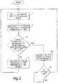
- FIG. 2is a flowchart for use in explaining a first method of detecting a shutdown condition in accordance with the present invention
- FIG. 3is a flowchart for use in explaining a first method of detecting a standby condition in accordance with the present invention
- FIG. 4is a block diagram showing parts of an inductive power transfer system according to a first embodiment of the present invention
- FIG. 5shows waveform diagrams for use in explaining operation of the FIG. 4 system
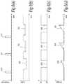
- FIGS. 6( a ) through 6( d )show waveform diagrams showing the timing of the various signals within the FIG. 4 system: FIG. 6( a ) shows a frequency of an AC voltage signal applied to a primary coil; FIG. 6( b ) shows a power drawn from the primary unit; FIG. 6( c ) shows a state of a switch in the primary unit; and FIG. 6( d ) shows the voltage across the switch in the primary unit;
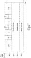
- FIG. 7is a diagram showing the load drawn during three different measurement operations
- FIG. 9is a block diagram showing parts of a primary unit in a power transfer system according to a second embodiment of the present invention.
- FIG. 10shows waveform diagrams for use in explaining operation of the FIG. 9 system
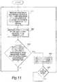
- FIG. 11is a flowchart for use in explaining a second method of detecting a shutdown condition in accordance with the present invention.
- FIG. 12is a block diagram showing parts of a power transfer system according to a third embodiment of the present invention.
- FIG. 1illustrates parts of an inductive power transfer system embodying the present invention.
- the system 1comprises a primary unit 10 and at least one secondary device 30 .
- the primary unit 10has a primary coil 12 and an electrical drive unit 14 connected to the primary coil 12 for applying electrical drive signals thereto so as to generate an electromagnetic field.
- a control unit 16is connected to the electrical drive unit 14 .
- This control unitgenerates an AC voltage signal 106 .
- the electrical drive unittakes the AC voltage signal 106 and converts it to an AC current signal in the primary coil 12 , so as to generate an induced electromagnetic field in the proximity of the primary coil 12 .
- the primary unit 10may have any suitable form but one preferred form is a flat platform having a power transfer surface on or in proximity to which each secondary device 30 can be placed.
- the fieldmay be distributed over a power transfer area of the surface, as described in GB-A-2388716.
- the secondary device 30is separable from the primary unit 10 and has a secondary coil 32 which couples with the electromagnetic field generated by the primary unit 10 when the secondary device 30 is in proximity to the primary unit 10 . In this way, power can be transferred inductively from the primary unit 10 to the secondary device 30 without direct electrical conductive contacts therebetween.
- the primary coil 12 and the secondary coils 32can have any suitable forms, but may for example be copper wire wound around a high-permeability former such as ferrite or amorphous metal.
- the secondary device 30is usually connected to an external load (not shown—also referred to herein as the actual load of the secondary device) and supplies the inductively-received power to the external load.
- the secondary device 30may be carried in or by an object requiring power such as a portable electrical or electronic device or a rechargeable battery or cell. Further information regarding designs of secondary device 30 and the objects which can be powered using the secondary devices 30 can be found in GB-A-2388716.
- the primary unit 10 in the FIG. 1 systemalso comprises a power measurement unit 100 connected to the control unit 16 .
- the power measurement unit 100performs a measurement of the electrical power drawn by the electrical drive unit 14 , on receipt of a signal provided by the control unit 16 .
- the power measurement unit 100provides an output representative of the electrical power drawn by the electrical drive unit 14 to the control unit 16 .
- the power drawn by the electrical drive unit 14is representative of the power drawn by the primary coil 12 and hence also the power drawn by all the secondary devices 30 plus other losses.
- control unit 16may enter a shutdown mode in which the drive to the primary coil 12 is reduced or stopped, preventing heating of the parasitic load.
- Another such conditionis when no secondary device 30 of the system is present in the vicinity of the primary unit 10 .
- Another such conditionis when there is at least one secondary device 30 present but none of the devices has a load currently requiring power.
- a loaddoes not require power, for example, when turned off or when, in the case of a rechargeable battery or cell, the battery or cell is fully charged.
- the control unit 16may enter a standby mode in which the drive to the primary coil 12 is reduced or stopped, preventing unnecessary power consumption in the primary unit 10 .
- FIG. 2is a flowchart for use in explaining a first method for detecting the presence of a substantial parasitic load in the vicinity of the primary unit in accordance with the present invention.
- step S 3the control unit 16 simply compares the measured power with a predetermined shutdown threshold. If the measured power exceeds the shutdown threshold value, the control unit 16 determines that the inductive power supply from the primary unit should be restricted or stopped.
- these lossesinclude losses in the primary unit itself and/or any secondary devices/host objects present. These losses include inefficiencies in the primary coil itself and any other components associated with the primary coil such as the electrical drive unit, for example I 2 R losses in the copper of the coil or effective series resistance of any resonating capacitor.
- the lossesalso include any magnetic losses in the primary unit and the secondary devices, for example magnetic is hysteretic loop losses in any coils associated with the primary unit and/or secondary devices.
- the control unit 16may employ, in addition to the measured power, first compensation information relating to losses in the primary unit itself, so as to compensate for those losses in step S 3 .
- the control unit 16may employ, in addition to the measured power, second compensation information relating to a parasitic load imposed on the primary unit by the or each secondary device, so as to compensate for the parasitic load of the or each secondary device in step S 3 .
- step S 4the control unit 16 places the primary unit in a shutdown mode in which the inductive power supply from the primary unit is restricted or stopped.
- the primary unitwill remain in the shutdown mode until it is reset in some way. Such a reset could be manually initiated by a user of the primary unit, or alternatively the control unit 16 could periodically start to supply inductive power again and repeat steps S 1 to S 3 to determine whether to remain in the shutdown mode or not.
- step S 3if the control unit 16 determines that the power supply does not need to be restricted or stopped, then in step S 6 secondary devices requiring power resume receiving power from the primary unit. Processing then returns, for example after a predetermined interval, to step S 1 again.
- step S 12the control unit 16 in the primary unit determines if the inductive power supply therefrom should be restricted or stopped in dependence upon the state information reported in step S 11 .
- the control unit 16determines that the inductive power supply should be restricted or stopped and processing proceeds to step S 13 in which the primary unit is set into the standby mode.
- the control unit 16also sets the primary unit into the standby mode.
- step S 5 of the method of FIG. 2once the primary unit has been set into the standby mode it may be reset into an operating mode again either by manual intervention from a user or automatically.
- step S 12If in step S 12 the control unit 16 determines that the inductive power supply should not be restricted or stopped based on the reported state information, then processing returns to step S 11 , for example after a predetermined interval. In this way, each secondary device present periodically has a reporting phase in which it reports its state information to the primary unit.
- FIGS. 2 and 3may be carried out independently of one another. However, it is preferable for the control unit 16 of the primary unit to be able to detect both when to enter the shutdown mode and to enter the standby mode. This can be achieved by a combination of the methods of FIGS. 2 and 3 as will now be described with reference to FIG. 4 .
- FIG. 4shows parts of an inductive power transfer system according to a first embodiment of the present invention.
- the system 1has a primary unit 10 and a secondary device 30 .
- FIG. 4also shows a parasitic load 500 on the primary unit, caused for example by a foreign object placed in the vicinity of the primary unit 10 .
- the secondary device 30in this case is assumed to be carried in or by a host object such as a portable electrical or electronic device. As explained hereinbefore the secondary device 30 and/or host object also inevitably impose a “friendly” parasitic load 501 on the primary unit 10 .
- the primary unit 10comprises a primary coil 12 , an electrical drive unit 14 , a control unit 16 and a power measurement unit 100 .
- the electrical drive unit 14has an input connected to an output of the control unit 16 supplying the AC voltage signal 106 .
- the output nodes of the electrical drive unit 14are connected to the primary coil 12 .
- the electrical drive unitis connected to the power supply 105 , via the power measurement unit 100 .
- the power supply 105supplies direct current to the electrical drive unit 14 .
- the electrical drive unit 14presents a high input impedance for the AC voltage signal 106 , so that essentially all the load current is drawn from power supply 105 .
- the control unit 16is a microprocessor in this embodiment.
- the microprocessorhas an inbuilt digital-to-analogue converter (not shown) to drive the output supplying the AC voltage signal 106 .
- an ASICcould be used to implement the control unit 16 , as well as some or all of the other circuit elements of the primary unit.
- the control unit 16 in this embodimentis adapted to modulate the AC voltage signal 106 for transmitting a synchronisation signal to a secondary device.
- the modulationis a frequency modulation of the AC voltage signal.
- Other modulation techniquessuch as amplitude or phase modulation may also be used.
- the control unit 16is adapted to send a synchronisation signal to any secondary devices 30 present.
- the secondary devices 30alter their load conditions in response to the synchronisation signal. This information is used to detect the conditions for entering the shutdown and standby modes.
- the power measurement unit 100It is desirable for the power measurement unit 100 to be operative without the need to disconnect the electrical supply to the primary coil 12 , as this means that supply to the secondary device 30 is not interrupted and it reduces stray electromagnetic interference into the surrounding environment. This is challenging because there is a lot of noise and the measurement is required in a short time.
- the power measurement unit 100comprises a switch 102 between the 0V supply in the power supply 105 and the ground terminal of the electrical drive unit 14 .
- the switch 102is controlled by the control unit 16 .
- the power measurement unitalso comprises a capacitor 101 connected between the positive and ground terminals of the electrical drive unit 14 .
- the capacitorfunctions as an energy storage unit.
- the analogue-to-digital converter outputis coupled to the control unit 16 .
- the power measurement unit 100When the switch 102 is closed, the power measurement unit 100 is not operative and the power is directly coupled from the power supply 105 to the electrical drive unit 14 .
- a power measurementis performed when the switch 102 is opened.
- the capacitor 101is now disconnected from the 0V rail on the power supply 105 , but still retains its charge.
- the electrical drive unit 14meanwhile continues to draw current and therefore discharges the capacitor 101 . In so doing the voltage across the capacitor 101 decays slightly and consequently the voltage at the point between the capacitor 101 and switch 102 rises slightly above 0V.
- the reservoir capacitor 107ensures that the positive supply voltage remains constant.
- the differential amplifier 103measures the voltage across the switch 102 and the resulting measurement is converted into a digital signal by the analogue-to-digital converter 104 and passed to the control unit 16 .
- the small temporary voltage drop across the electrical drive unit 14does not have any noticeable effect on the power transfer to the secondary devices 30 .
- V +is the supply voltage, assuming V 1 , V 2 ⁇ V + . It is advantageous to sample the voltage level at the same point in the cycle, so that the periodic perturbation in voltage is removed (also shown in FIG. 5 ). The switch 102 is then closed again to reconnect the power supply 105 to the electrical drive unit 14 .
- the change measured by the circuitry during the disconnection of the power supplymight be a change in current, for example measured as a voltage drop across a series resistor.
- the primary unit 10further comprises a calibration unit 29 in this embodiment.
- the calibration unit 29stores compensation information about the losses in the primary unit (e.g. electrical or magnetic losses). By design, at manufacture, and/or periodically thereafter, the losses in the primary unit may be calibrated and stored within the calibration unit 29 .
- the calibration unit 29supplies the stored information to the control unit 16 to enable the control unit 16 to subtract the losses from the total measurement, thus calculating a number for the loss due to parasitic loads alone.
- This calibration unit 29may vary the compensation information to cope with variable losses in the primary unit, for example losses which vary with temperature.
- the secondary device 30comprises a secondary coil 32 , a rectifier 34 , a secondary control unit 36 , a dummy load switch 38 , a dummy load 40 , a load switch 42 , a storage unit 44 and an actual load 46 .
- the dummy load switch 38 and the load switch 42may each be an FET, for example.
- the dummy load 40is, for example, a resistor.
- the storage unit 44is a capacitor in this embodiment but an inductor could be used instead.
- the actual load 46is external to the secondary device 30 in this embodiment and is part of the host object. It could be a battery charge controller for a Lithium-ion cell.
- the detection unit 200may be a zero crossing detector which passes a signal to the control unit every time the AC signal crosses zero volts.
- the control unit 36may then comprise an internal clock and counter circuit (not shown). The clock and counter circuit may be used to measure the time interval between successive zero crossings and hence derive the frequency of the AC signal 106 imposed by the primary unit control unit 16 .
- the secondary unitmay detect a change in frequency and respond by altering its load conditions by adjusting switches 42 and 38 .
- load detection circuit 200may comprise a threshold detector for digital amplitude modulation or an analogue-to-digital converter for multiple level amplitude modulation or a phase detector for phase modulation or any combination thereof.
- the host object incorporating the secondary device 30is placed on or in proximity to the primary unit 10 .
- Switch 102is closed.
- the control unit 16applies an AC voltage signal 106 to the electrical drive unit 14 .
- the electrical drive unit 14takes DC power from the power supply 105 and amplifies the AC voltage signal 106 and applies it to the primary coil 12 .
- the primary coil 12In the operating mode, the primary coil 12 generates an electromagnetic field in the vicinity of the primary unit 10 .
- the secondary coil 32couples with this field and an alternating current is induced in the coil by the field.
- the dummy load switch 38is open and the load switch 42 is closed.
- the alternating current induced in the secondary coil 32is rectified by the rectifier 34 and the rectified current is supplied via the load switch 42 to the storage unit 44 and the actual load 46 . In this way, power is transferred inductively from the primary unit 10 to the secondary device 30 and from there to the load 46 .
- the storage unit 44stores energy in the operating mode.
- the control unit 16 in the primary unit 10Whilst in the operating mode, from time to time the control unit 16 in the primary unit 10 initiates a measurement.
- the measurementstarts with the primary unit 10 sending a synchronisation signal to the secondary unit 30 by applying a momentary frequency change to the AC drive voltage signal 106 .
- the secondary devices 30receive the AC voltage signal and in each receiving secondary device the detection unit 200 in conjunction with the control unit 36 determine when the synchronisation signal has occurred.
- the secondary unitspresent alter their load conditions for a set time period and the primary unit 10 measures the total load (power drawn) within this time period.
- the primary unit 10initiates a series of three power measurements for the purposes of determining: 1) whether the there is a parasitic metal present requiring it to enter the shutdown mode to prevent overheating and 2) if there are no devices requiring any power, such that the unit can enter the standby mode.
- the behaviour of the primary unit 10 and the secondary device 30is slightly different in each of the three measurements of the series.
- the secondary control unit 36has the dummy load switch 38 open so that the dummy load 40 is not connected to the secondary coil 32 .
- the first measurementis a measure of the power delivered to any parasitic loads 500 from foreign objects in the vicinity of the primary unit and any parasitic load 501 imposed by losses in the secondary device and/or its host object and any losses in the primary unit itself.
- operation during the first measurementcorresponds to the steps S 1 to S 3 of FIG. 2 above.
- the secondary control unit 36selectively closes the dummy load switch 38 .
- the secondary control unit 36decides whether to have the dummy load switch 38 open or closed during the second measurement based on the power requirement of the actual load 46 . If the load 46 does not require any power at the present time, for example because it has a rechargeable battery which is presently fully charged, then the dummy load switch 38 is kept open during the second measurement. If, on the other hand, the load 46 does require power at the present time, then the dummy load switch 38 is closed so that the dummy load 40 is connected to the primary coil 32 .
- the control unit 16produces another measure of the power load during the second measurement. If the second power measurement is substantially different from the first power measurement, the control unit 16 detects that a secondary device requiring power is present in the vicinity of the primary unit. Thus, operation during the second measurement corresponds to steps S 11 and S 12 of FIG. 3 above.
- the secondary control unit 36always closes the dummy load switch 38 so that the dummy load 40 is connected to the secondary coil 32 .
- Another power measureis taken by the control unit 16 in the primary unit.
- the measurementis the sum of the parasitic loads 500 , the parasitic load 501 of the secondary device and/or host object, primary unit losses, and the dummy load 40 .
- the control unitcalculates the value of the total of the dummy loads 40 in all of the secondary devices present in the vicinity of the primary unit.
- FIGS. 6( a ) through 6( d )The timing of the various signals and measurements is illustrated diagrammatically in FIGS. 6( a ) through 6( d ) (not to scale).
- FIG. 6( a )represents the frequency of the drive applied to the primary coil 12
- FIG. 6( b )represents the load presented by the secondary device 30
- FIG. 6 ( c )represents the state of the switch 102 in the primary unit 10
- FIG. 6( d )represents the voltage across the switch 102 .
- the primary unit 10first momentarily changes the frequency of the drive to the primary coil 510 , 511 , 512 , for the first, second and third measurements respectively. Then each secondary device 30 isolates its actual load 513 , 514 , 515 and depending on the circumstances introduces a dummy load 514 , 515 .
- the switch 102 in the primary unitopens 516 , 517 , 518 .
- the voltage across the switch 106ramps up 519 , 520 , 521 . This voltage is sampled at several points within this window to measure the power.
- On the first measurementthere is no dummy load 513 , on the second measurement each device only connects the dummy load if its actual load requires power 514 , on the third measurement the dummy load is always connected 515 .
- the secondary device 30knows which measurement is which by the order in which they occur. If there has been a long gap of say a few ms since the last synchronisation signal then the secondary device knows that it must be the first measurement. The secondary device can count the number of periods in the received alternating current to determine this. The second and third measurement synchronisation signals naturally follow in that order within a set number of cycles. In order to get more accurate measurements, it is possible to average each measurement over a number of sequences.
- Each dummy load 40 in a secondary device 30 in the system of this embodimentis set to a particular value (at manufacture or during calibration or testing) so that the value represents the parasitic load 501 imposed by the secondary device concerned and/or by its host object.
- the total dummy load for all secondary devices presentcan be used by the control unit 16 as second compensation information to compensate for the parasitic loads 501 of the secondary devices present. For example, if the control unit 16 detects that a substantial parasitic load 500 is present in the vicinity of the primary unit when the measured power exceeds some threshold, the threshold may be increased by an amount dependent on the total parasitic load 501 of all the secondary devices present, so that the detection of parasitic loads 500 from foreign objects is not influenced by the number of secondary devices present.
- FIG. 7shows diagrammatically the load drawn for the three measurements.
- the load drawnis the sum of: the losses associated with the primary coil in the primary unit (pad) 543 , the parasitic load associated with foreign metal objects 542 , ‘friendly parasitics’ of metal associated with host object (portable device) to be powered 541 and the current load associated with all the secondary devices 540 .
- the first measurement 530has all of these components except the load 540 . If no devices require power then the second measurement 531 will be the same as the first measurement 530 , so the primary unit can be placed into the standby mode (step S 4 in FIG. 3 ). However, if at least one device requires power then the second measurement 531 will be greater than the first measurement 530 , and power is required.
- each secondary device 30connects its dummy load.
- the dummy load of each device 40is made equal to that device's ‘friendly parastics’.
- the primary unit loss 543is known (and stored in the calibration unit 29 ).
- the calculated ‘friendly parasitics’ 541 and the known primary unit loss 543may be subtracted from the first measurement 530 . If this figure is above a certain threshold then the unit can be placed into the shutdown mode (step S 4 in FIG. 2 ).
- a system embodying the present inventionis capable of measuring loads imposed on the primary unit sensitively, for example to within 50 mW or so. With this degree of sensitivity, it is possible to ensure that very little power is coupled into parasitic loads 500 such as foreign objects.
- FIG. 8is a diagram illustrating the different modes of operation in the FIG. 4 system and the conditions for switching between these different modes.
- the three modes of operationare an operating mode, a shutdown mode and a standby mode.
- the primary unitIn the operating mode, the primary unit is in the normal state (driven condition) most of the time, but periodically does a sequence of three measurements as described above. If the result of the measurement sequence is that no secondary device requires power, the primary unit goes into a standby mode. If the result of the measurement sequence is that a significant parasitic load 500 is present, the primary unit goes into a shutdown mode.
- the electrical drive unit 14In the standby mode, the electrical drive unit 14 is stopped for most of the time, thus consuming little power. Periodically the primary unit enters the normal mode, then does a series of measurements in respective probing periods, to check whether it should enter either the operating mode or the shutdown mode. Otherwise it remains in the standby mode.
- the shutdown modeis functionally identical to standby mode. However, the two modes may be distinguished by some user-interface feature such as an LED to prompt the user to remove any substantial parasitic load 500 .
- inductive power transfer systemswhich rather than have a single primary coil 12 have a plurality of coils, for instance as described in GB-A-2398176.
- the present inventionmay be used in such a configuration directly.
- the electrical drive unit 14not only supplies the AC current drive to the first coil, but also to the second coil.
- the transmitted synchronisation signalswill be present on both coils.
- the power measurementsince the current measurement is performed by determining the current drawn from the power supply, the power measurement will be the total sum of all the load drawn regardless of what proportion is drawn by each coil. In such a 2 channel rotating system, the orientation of the secondary device 30 is arbitrary. Therefore the secondary device 30 will see a +/ ⁇ 180° phase difference relative to the primary unit. Therefore the secondary devices 30 , must each lift their load for at least 1 ⁇ 2 cycle each side of the primary unit's measurement period.
- a fourth measurementmay be made. This measure is initiated by the control unit 16 in the primary unit 10 , and results in the power measurement unit 100 taking a power measurement, but without any synchronisation signal being sent to the primary coil 12 .
- the secondary units 30do not alter their load conditions and this is therefore a measurement of the power whilst in the operating state. This measurement can be performed at any time other than during a measurement sequence of the first three measurements.
- This fourth measurementis used to determine if the total load drawn is greater than the power specification of the device and hence put the primary unit into an ‘overload state’.
- the ‘overload’ stateis functionally identical to the ‘shutdown state’, but may be distinguished by some use-interface feature such as an LED.
- the electrical drive unit 14is adapted to modify the magnitude of its output current into the primary coil for the purpose of varying the field magnitude of the generated magnetic field. This would allow the field magnitude to be reduced for small loads, thereby conserving electrical power.
- An implementation of this featureis to use the first and second measurements in a different way, not only to detect if devices require power, but also to set the required field magnitude. Instead of switching in the dummy load 40 during the second measurement if it needs power, a secondary device could switch in its dummy load if it is not getting sufficient power. The presence of a difference between the first and second measurements would then be taken by the primary unit as a “not enough power” signal. The primary unit 10 could periodically bring the field up to maximum magnitude and then gradually reduce it until the difference between the first and second measurements was greater than a certain threshold (“not enough power” signal). This way the primary unit would always be operating at the lowest possible field magnitude.
- the secondary devicesare adapted for changing the magnitude of their dummy loads dynamically.
- Thiscould be achieved for instance by incorporating a load which may be altered in value by a control means.
- a simple examplemight be a resistor ladder with an array of switches, which may be arranged with values in binary increments.
- the loadmay be adapted to have a continuously variable magnitude by use of a transistor circuit or by incorporation of some other nonlinear element.
- Another way of dynamically changing the loadis to modulate the switch 40 which connects the load, such that when the power measurement is averaged over the measurement time interval, the effective load is altered.
- the pulse width or duty cyclecould be altered to change the effective load magnitude.
- the ability to change the dummy load dynamicallyis useful for devices whose ‘friendly parasitic’ load may change.
- a self-charging batterymay have a different ‘friendly parasitic’ load when charged alone, compared to when it is charged whilst connected to a mobile phone.
- the control unit 36could detect whether the phone was attached and modify the dummy load accordingly.
- the phonecould communicate its ‘friendly parasitics’ to the battery.
- Other removable attachments which contribute additional ‘friendly parasitic’ loadcould also be detected and the dummy load modified accordingly. These include for example, but are not limited to, removable camera attachments, cases and speakers.
- this methodcould be used such that the primary unit 10 could deduce other information about the secondary device 30 .
- the primary unit 10could receive information about the serial number, model number, power requirements or other information stored in the secondary device.
- the loadcould be altered dynamically either synchronously or asynchronously to achieve this.
- Amplitude modulation or pulse width modulationmay be used.
- a number of ‘bits’ or ‘symbols’may be used (where a ‘symbol’ represents a plurality of amplitude levels or pulse width durations and therefore more than one ‘bit’).
- the primary unit 10could communicate information to the secondary device 30 , other than synchronisation signals, by means of modulating the AC voltage signal 106 applied to the electrical drive unit.
- This informationmay include but is not limited to information about the primary unit 10 , such as cost of a charge, power capability, codes; information about the location of the primary unit, such as nearby facilities; and other information such as advertising material.
- the secondary device 30could receive such information by means of the detection element 200 and the control unit 36 .
- the standby detect featuremay be implemented.
- the parasitic detect featuremay be implemented.
- the overload detect featuremay be implemented.
- Information about the secondary device 30may be deduced by the primary unit, without implementing other features.
- informationmay be sent from the primary unit to the secondary device without implementing other features. Further measurements may be used to implement additional features. It should be appreciated that the labelling of each measurement is purely for identification purposes and the measurements may be performed in any order.
- synchronisation signalsmay differ in frequency offset, amplitude or phase
- sending only a first synchronisation signal and deducing the timing of the other measurementsmay be means of either a counter to count cycles of the received signal or an internal clock within each secondary device. It is even possible to perform the measurements back to back, with no substantial gap between them. Alternatively measurements are initiated by the secondary device rather than the primary unit.
- the secondary devicecould initiate a ‘preamble’ dynamic load modulation, which the primary unit would detect and then synchronise on, so that its power measurements coincided with the timing of the secondary device adapting its load conditions.
- the ‘preamble’could involve the use of some unique identifier, so that each secondary device may be interrogated independently. ‘Preambles’ could also be used in communication from the primary unit to the secondary device to address each device independently.
- the dummy loadmay be used to represent the ‘friendly parasitic’ load of the host device.
- the ratio between the dummy load value and the friendly parasitic load to be communicatedis not limited to any particular value.
- the dummy loadcould be twice or three times the ‘friendly parasitic’ value or a noninteger multiple of the value.
- the primary unitcan deduce the total ‘friendly parasitic load’ so long as it knows what the ratio is.
- a first dummy loadmay be used for the second measurement and a second dummy load may be used for the third measurement.
- the first dummy loadwould be used for standby detection and the second dummy load would be representative of the ‘friendly parasitics’. This is particularly advantageous if the secondary devices have widely varying parasitic loads.
- the first dummy loadcould also be used for determining the power requirements of the secondary devices requiring charging, rather just making a standby decision.
- the dummy load valuewould be adapted to be representative of the power requirements of that particular device.
- the first and second dummy loadsmay be implemented by a single dynamically variable dummy load described above, or fixed loads may be used, or a combination of the two.
- the simplest power measurementmay comprise inserting a series resistor on one supply rail. The voltage could be measured across that resistor and the power deduced from the observed voltage and the known resistor value. With such a method it may be desirable to incorporate a switch across the resistor, so that during periods outside of the measurement time, the resistor may be short circuited, such that there is no unnecessary power dissipation in the resistor.
- Another method of power measurementis to measure the power within the electrical drive unit. For instance, it is desirable for the electrical drive to the coil or coils to be regulated by means of a feedback circuit.
- the feedback signalmay be used to derive a power measurement.
- the power measurementinvolves disconnecting the power to the primary coils and detecting the decay in the undriven resonant circuit.
- the act of disconnecting the power to the primary coil 12also has the effect of modulating the signal in the primary coil and as a result the signal received in the secondary device 30 .
- FIG. 9shows a second embodiment of a power transfer system according to the present invention.
- the primary unit 110comprises a primary coil 112 , an electrical drive unit 114 , a control unit 116 and a decay measurement unit 118 .
- the electrical drive unit 114 in this embodimenthas a conventional half bridge configuration in which a first switch 120 is connected between a first power supply line of the primary unit and an output node of the electrical drive unit, and a second switch 121 is connected between the output node and a second power supply line of the primary unit.
- the first and second switches 120 and 121may, for example, be field-effect transistors (FETs).
- the electrical drive unit 114also comprises a drive controller 119 which applies control signals to the switches 121 and 122 to turn them on and off.
- the drive controller 119has a control input connected to an output of the control unit 116 .
- the output node of the electrical drive unit 114is connected via a capacitor 117 to one side of the primary coil 112 .
- the control unit 116is a microprocessor in this embodiment.
- an ASICcould be used to implement the control unit 116 , as well as some or all of the other circuit elements of the primary unit.
- the decay measurement unit 118comprises a resistor 125 which has a first node connected to one side of a switch 128 and a second node connected to the second power supply line.
- the resistor 125is a low-value resistor.
- the decay measurement unit 118further comprises an operational amplifier 126 having an input connected to the first node of the resistor 125 .
- the decay measurement unit 118also comprises an analog-to-digital converter (ADC) 127 connected to an output of the operational amplifier 126 . An output of the ADC 127 is connected to a measurement input of the control unit 116 .
- ADCanalog-to-digital converter
- the other side of the switch 128is connected to the other side of the primary coil 112 .
- a snubber unit 122is connected in parallel with the switch 128 .
- the snubber unit 122comprises a capacitor 123 and a resistor 124 connected in series with one another.
- the calibration unit 129is the same as the calibration unit 29 in FIG. 4 .
- Each secondary device in this embodimentcan be substantially the same as the secondary device 30 in FIG. 4 , and accordingly a description thereof is omitted here and no secondary device is illustrated in FIG. 9 .
- FIG. 9Operation of the FIG. 9 system will now be described with reference to FIG. 10 .
- the systemhas a normal state in which the control unit 116 causes the electrical drive unit 114 to apply drive signals to the primary coil 112 to cause it to oscillate. It will be appreciated that in the operating mode, the system is in this state for almost all the time.
- the switch 128is closed, and the circuit including the capacitor 117 and primary coil 112 forms a resonant tank.
- the next stateis a “snub” state.
- the application of drive signals to the primary coil 112 by the electrical drive unit 114is suspended under the control of the control unit 116 .
- the drive controller 119closes the switch 121 .
- the control unit 116also opens the switch 128 at a time when most of the energy in the resonant tank resides in the capacitor 117 .
- the opening of the switch 128brings the snubber unit 122 in series with the resonant tank.
- the snubber unit 122quickly dissipates any energy which remains in the primary coil 112 , stopping it from resonating within one cycle or so. Most of the energy stored in the resonant tank is left in the capacitor 117 .
- the sudden cessation of cyclesis detected by the detection unit 200 and the secondary control unit 36 in the secondary device 30 .
- the secondary control unit 36opens the load switch 42 .
- he detection unit 200 in FIG. 4needs to be modified to detect the sudden cessation of cycles in the snub state in the present embodiment.
- a threshold detector(as mentioned above) may be used as the detection unit in the present embodiment.
- the snub stateis used as the synchronisation signal to the secondary device, though the other forms (e.g. frequency or phase modulation) could also be used. It is not always necessary to have a synchronisation signal before every measurement as described above.
- the systemthen enters the decay state from the snub state.
- the control unit 116closes the switch 128 , removing the snubber unit 122 from the resonant tank, and thus allowing the energy in capacitor 117 to flow again within the resonant tank.
- the resonant tankoperates in an undriven resonating condition. Energy stored in the resonant tank decays over the course of time in the decay state.
- the decay measurement unit 118measures the energy decay in the resonant tank by measuring the current flowing through the primary coil 112 . The same current flows through the resistor 125 and generates a voltage at the first node of that resistor. This voltage is buffered by the operational amplifier 126 and converted into a digital signal by the ADC 127 . The resulting digital signal is applied to the measurement input of the control unit 116 .
- FIG. 10shows how the current flowing through the primary coil 12 varies in the normal, snub and decay states which occur during a power measurement.
- the digital signals representing the current flowing in the primary coil within a measurement periodare received and processed within the control unit 16 to calculate a measure of the rate of energy decay in the resonant tank.
- the energy stored in the resonant tank of the primary unit at any given momentcan be calculated if the inductance and peak current are known, or if the capacitance and peak voltage are known, or combinations thereof.
- the capacitanceis known by design
- the peak current and voltagecan be measured by suitable circuitry, and the inductance can be deduced by observing the natural resonant frequency during the measurement and applying the formula:
- the power measure, Pis given by the rate of decay of energy (and thus the loss) from the resonant tank and can be calculated by measuring E 1 at time T 1 and E 2 at another time T 2 .
- a second method for detecting a shutdown condition in accordance with the present inventionwill be described with reference to FIG. 11 .
- This methodcan be used in the FIG. 1 system.
- each secondary device which is in the power-requiring statesupplies information to the primary unit relating to its own power requirement.
- the power requirement informationmay take many different forms.
- the informationmay comprise a binary part used to indicate either “no power required” or “power required”.
- supplemental informationmay be provided by the secondary device to indicate the amount of power required.
- the power requirement informationmay simply be representative of the amount of power required, and “0” may be transmitted if the device requires no power at all.
- the power requirement of the secondary devicemay already be known to the primary unit. For example, it may be known that all secondary devices of a certain type will have a particular power requirement. In this case, the power requirement information may simply be a code (or some other identifying information) indicating the type of the secondary device.
- All of the secondary devicesmay supply the power requirement information simultaneously to the primary unit.
- each secondary devicesupplies its power requirement information individually in turn to the primary unit.
- the power requirement information supplied by each secondary device that has the power-requiring stateis received by the primary unit.
- step S 22the control unit 16 in the primary unit causes the power measurement unit 100 to measure the power drawn by the secondary devices from the primary unit as described previously. In practice, the measured power will also reflect any losses in the system.
- step S 23the control unit 16 determines whether inductive power supply from the primary unit should be restricted or stopped in dependence upon the measured power in step S 22 and the power requirement information received in step S 21 . For example, the control unit 16 calculates a sum of the respective power requirements of all of the secondary devices that are in the power-requiring state. This sum is compared with the measured power found in step S 22 . If the measured power exceeds the sum of the power requirements by more than a threshold value, then the control unit determines that a substantial parasitic load must be present in the vicinity of the primary unit. In that case, processing proceeds to step S 24 in which the primary unit enters the shutdown mode and inductive power supply from the primary unit is restricted or stopped. As described previously in relation to the method of FIG. 2 , the system may be reset manually or automatically in step S 25 .
- step S 23If in step S 23 the control unit 16 determines that the power supply need not be restricted or stopped, then processing returns to step S 21 , for example after a predetermined time interval.
- the shutdown threshold employed in step S 23may be adjusted.
- One way in which this can be doneis for each secondary device (whether or not in the power-requiring state) to also supply to the primary unit information relating to its “friendly parasitic” load.
- losses as in the primary unitmay be accounted for using a calibration unit as described with reference to FIG. 4 .
- FIG. 12shows parts of a power transfer system according to a third embodiment of the present invention. This system implements the shutdown detection method of FIG. 11 using an RFID communication method.
- the FIG. 12 systemcomprises a plurality of secondary devices 600 1 , 600 2 , . . . , 600 n .
- the system of FIG. 12also comprises a primary unit 700 .
- the primary unit 700comprises an RFID unit 710 , a control unit 720 and a power measurement unit 730 .
- the control unit 720corresponds generally to the control unit 16 described previously with reference to FIG. 1
- the power measurement unit 730corresponds generally to the power measurement unit 100 described in reference to FIG. 1 .
- each secondary device 600comprises its own load measuring unit 610 and an RFID unit 620 .
- the load measuring unit 610measures the power being supplied to the actual load ( 46 in FIG. 4 ) of that secondary device.
- the load measuring unit 610may measure the current and/or voltage being supplied to the actual load 46 and may possibly integrate these measures over time for averaging purposes.
- the averaging periodmay be ten seconds.
- the RFID unit 620 in each secondary deviceis capable of communicating with the RFID unit 710 in the primary unit 700 using an RFID link 630 .
- the load measure produced by the load measuring unit 610 in each secondary deviceis supplied to the RFID unit 620 in the device and then transmitted via the relevant RFID link 630 to the RFID unit 710 in the primary unit.
- the RFID unit 710may poll the RFID unit 610 in each of the secondary devices from time to time.
- the RFID unit 620 that has been polledtransmits its load measure. This load measure corresponds to the power requirement information of step S 21 in FIG. 11 .
- the power measurement unit 730 in the primary unitalso measures the power being drawn by the secondary devices from the primary unit, as in step S 22 in FIG. 11 . Then, the control unit 720 determines, in dependence upon the measured power and the sum of the received load measures from the secondary devices, whether or not the power supply to the secondary devices should be restricted or stopped. In particular, if the measured power from the power measurement unit 730 exceeds the sum of the load measures from the secondary devices by more than a shutdown threshold, then the control unit 720 concludes that a substantial parasitic load must be present and places the primary unit in the shutdown mode, as in step S 24 in FIG. 11 .
- the load measure produced by each secondary devicemay represent a total load from the secondary device including the amount of power required by the actual load and any friendly parasitic load of the secondary device/host object. If the actual load requires no power the load measure may change to represent only the friendly parasitic load.
- every RFID unit 620has an unique code (or one which will be practically unique based on statistics).
- the RFID unit 710 in the primary unitwould send out a signal requesting that all RFID units 620 within a certain range reply.
- the RFID units 620send out their reply in code (e.g. Manchester code), so that the RFID unit 710 can tell if more than one device has replied.
- the primary unitgradually narrows down the range until it can uniquely identify the code of each device present. Typically, it may halve the range of codes in each iteration to home in quickly.
- any suitable communication linkcan be used to permit each secondary device to communicate its power requirement information to the primary unit.
- infrared or ultrasound communicationcould be used.
- each secondary devicecould vary the load it imposes on the primary unit to communicate the power requirement information.
- each secondary devicecould impose a dummy load representing the amount of power required by its actual load.
- all the secondary devices in the power-requiring statecan impose their respective dummy loads simultaneously, so that the primary unit can directly derive the sum of the power requirements of all the secondary devices in one measurement.
- the dummy loadmay represent a total load from the secondary device including the amount of power required by the actual load and any friendly parasitic load of the secondary device/host object.
- any reference to claim elements as “at least one of X, Y and Z”is meant to include any one of X, Y or Z individually, and any combination of X, Y and Z, for example, X, Y, Z; X, Y; X, Z; and Y, Z.
Landscapes
- Engineering & Computer Science (AREA)
- Power Engineering (AREA)
- Computer Networks & Wireless Communication (AREA)
- Physics & Mathematics (AREA)
- Electromagnetism (AREA)
- General Physics & Mathematics (AREA)
- Radar, Positioning & Navigation (AREA)
- Automation & Control Theory (AREA)
- Charge And Discharge Circuits For Batteries Or The Like (AREA)
- Emergency Protection Circuit Devices (AREA)
Abstract
Description
- A primary unit having at least one primary coil, through which it drives an alternating current, creating a time-varying magnetic flux.
- A secondary device, separable from the primary unit, containing a secondary coil. When the secondary coil is placed in proximity to the time-varying flux created by the primary coil, the varying flux induces an alternating current in the secondary coil, and thus power may be transferred inductively from the primary unit to the secondary device.
- If the resistance of any metal is high, for example if it is impure or thin.
- If the material is ferromagnetic, for example steel. Such materials have high permeability, encouraging a high flux density within the material, causing large eddy currents and therefore large I2R losses.
- In EP0533247 and U.S. Pat. No. 6,118,249 the secondary device modulates its inductive load during charging, causing a corresponding variation in the power taken from the primary unit. This indicates to the primary unit that it should stay out of the standby state.
- In EP1022840 the primary unit varies the frequency of its drive, and thus the coupling factor to a tuned secondary unit. If the secondary unit is not taking power, there is no difference in the power taken as the frequency is swept and thus the primary unit goes into a standby state.
- In U.S. Pat. No. 5,536,979 the primary unit simply measures the power flowing in the primary coil, and enters a pulsing standby state if this is below a threshold.
- In U.S. Pat. No. 5,896,278 the primary unit contains detecting coils which have power coupled back into them according to the position of the secondary device. If the device is not present the primary unit enters a standby mode.
- In U.S. Pat. No. 5,952,814 the secondary device has a mechanical protrusion which fits a slot in the primary unit, activating it.
- In U.S. Pat. No. 6,028,413 the primary unit drives two coils, and there are a corresponding two power receiving secondary coils in the secondary unit. The primary unit measures the power delivered from each primary coil and enters standby mode if it is below a threshold.
- As mentioned above, in EP1022840 the primary unit varies the frequency of its drive. In this system, the secondary device is tuned, so this frequency variation will result in a variation of the power taken from the primary unit. If the load is instead a piece of metal, then varying the frequency will not have as much effect and the primary unit will enter a shutdown state.
- As mentioned above, in U.S. Pat. No. 5,952,814 a key in the secondary device activates the primary unit. The assumption is that if a secondary device is present then this will physically exclude any foreign objects.
- As mentioned above, in U.S. Pat. No. 6,028,413 the primary unit supplies power to the secondary device by driving two primary coils. If the amount of power supplied by the two coils is different, the primary unit assumes that the load is not a valid secondary device and enters shutdown mode.
where V+ is the supply voltage, assuming V1, V2<<V+. It is advantageous to sample the voltage level at the same point in the cycle, so that the periodic perturbation in voltage is removed (also shown in
E=½LÎ2=½C{circumflex over (V)}2
where E is the energy, L the inductance, Î is the peak current, C is the capacitance and {circumflex over (V)} is the peak voltage.
Claims (20)
Priority Applications (1)
| Application Number | Priority Date | Filing Date | Title |
|---|---|---|---|
| US16/117,755US10804751B2 (en) | 2004-05-11 | 2018-08-30 | Controlling inductive power transfer systems |
Applications Claiming Priority (11)
| Application Number | Priority Date | Filing Date | Title |
|---|---|---|---|
| GB0410503.7 | 2004-05-11 | ||
| GB0410503AGB2414120B (en) | 2004-05-11 | 2004-05-11 | Controlling inductive power transfer systems |
| GB0502775AGB0502775D0 (en) | 2004-05-11 | 2005-02-10 | Controlling inductive power transfer systems |
| GB0502775.0 | 2005-02-10 | ||
| US11/569,035US7605496B2 (en) | 2004-05-11 | 2005-05-11 | Controlling inductive power transfer systems |
| PCT/GB2005/001824WO2005109597A1 (en) | 2004-05-11 | 2005-05-11 | Controlling inductive power transfer systems |
| US12/556,121US8039995B2 (en) | 2004-05-11 | 2009-09-09 | Controlling inductive power transfer systems |
| US13/236,066US8508077B2 (en) | 2004-05-11 | 2011-09-19 | Controlling inductive power transfer systems |
| US13/927,173US9331526B2 (en) | 2004-05-11 | 2013-06-26 | Controlling inductive power transfer system |
| US15/083,955US10069350B2 (en) | 2004-05-11 | 2016-03-29 | Controlling inductive power transfer system |
| US16/117,755US10804751B2 (en) | 2004-05-11 | 2018-08-30 | Controlling inductive power transfer systems |
Related Parent Applications (1)
| Application Number | Title | Priority Date | Filing Date |
|---|---|---|---|
| US15/083,955ContinuationUS10069350B2 (en) | 2004-05-11 | 2016-03-29 | Controlling inductive power transfer system |
Publications (2)
| Publication Number | Publication Date |
|---|---|
| US20180375389A1 US20180375389A1 (en) | 2018-12-27 |
| US10804751B2true US10804751B2 (en) | 2020-10-13 |
Family
ID=34702526
Family Applications (6)
| Application Number | Title | Priority Date | Filing Date |
|---|---|---|---|
| US11/569,035Active2025-10-20US7605496B2 (en) | 2004-05-11 | 2005-05-11 | Controlling inductive power transfer systems |
| US12/556,121Expired - LifetimeUS8039995B2 (en) | 2004-05-11 | 2009-09-09 | Controlling inductive power transfer systems |
| US13/236,066Expired - LifetimeUS8508077B2 (en) | 2004-05-11 | 2011-09-19 | Controlling inductive power transfer systems |
| US13/927,173Active2026-02-25US9331526B2 (en) | 2004-05-11 | 2013-06-26 | Controlling inductive power transfer system |
| US15/083,955Active2025-12-25US10069350B2 (en) | 2004-05-11 | 2016-03-29 | Controlling inductive power transfer system |
| US16/117,755Expired - LifetimeUS10804751B2 (en) | 2004-05-11 | 2018-08-30 | Controlling inductive power transfer systems |
Family Applications Before (5)
| Application Number | Title | Priority Date | Filing Date |
|---|---|---|---|
| US11/569,035Active2025-10-20US7605496B2 (en) | 2004-05-11 | 2005-05-11 | Controlling inductive power transfer systems |
| US12/556,121Expired - LifetimeUS8039995B2 (en) | 2004-05-11 | 2009-09-09 | Controlling inductive power transfer systems |
| US13/236,066Expired - LifetimeUS8508077B2 (en) | 2004-05-11 | 2011-09-19 | Controlling inductive power transfer systems |
| US13/927,173Active2026-02-25US9331526B2 (en) | 2004-05-11 | 2013-06-26 | Controlling inductive power transfer system |
| US15/083,955Active2025-12-25US10069350B2 (en) | 2004-05-11 | 2016-03-29 | Controlling inductive power transfer system |
Country Status (4)
| Country | Link |
|---|---|
| US (6) | US7605496B2 (en) |
| EP (1) | EP1751834B1 (en) |
| GB (1) | GB2414121B (en) |
| WO (1) | WO2005109597A1 (en) |
Cited By (1)
| Publication number | Priority date | Publication date | Assignee | Title |
|---|---|---|---|---|
| US11979201B2 (en) | 2008-07-02 | 2024-05-07 | Powermat Technologies Ltd. | System and method for coded communication signals regulating inductive power transmissions |
Families Citing this family (427)
| Publication number | Priority date | Publication date | Assignee | Title |
|---|---|---|---|---|
| GB2414121B (en)* | 2004-05-11 | 2008-04-02 | Splashpower Ltd | Controlling inductive power transfer systems |
| GB2414120B (en)* | 2004-05-11 | 2008-04-02 | Splashpower Ltd | Controlling inductive power transfer systems |
| JP4096315B2 (en)* | 2004-08-04 | 2008-06-04 | セイコーエプソン株式会社 | Display system |
| US9596031B2 (en) | 2005-03-01 | 2017-03-14 | Alexander Ivan Soto | System and method for a subscriber-powered network element |
| US9515747B2 (en) | 2005-03-01 | 2016-12-06 | Alexander Ivan Soto | System and method for a subscriber-powered network element |
| US8543008B2 (en)* | 2005-03-01 | 2013-09-24 | Alexander I Soto | System and method for a subscriber powered network element |
| NZ540927A (en)* | 2005-06-22 | 2008-03-28 | Traffic Electronics Ltd | Communication system for inductive power transfer system |
| CN101860089B (en) | 2005-07-12 | 2013-02-06 | 麻省理工学院 | wireless non-radiative energy transfer |
| US7825543B2 (en) | 2005-07-12 | 2010-11-02 | Massachusetts Institute Of Technology | Wireless energy transfer |
| US7514899B2 (en) | 2005-11-18 | 2009-04-07 | Avago Technologies Ecbu Ip (Singapore) Pte. Ltd. | Method and apparatus for optical wireless charging |
| WO2007069293A1 (en)* | 2005-12-12 | 2007-06-21 | Matsushita Electric Industrial Co., Ltd. | Contactless charging-type battery system, charging device, and battery pack |
| US7952322B2 (en) | 2006-01-31 | 2011-05-31 | Mojo Mobility, Inc. | Inductive power source and charging system |
| US11201500B2 (en) | 2006-01-31 | 2021-12-14 | Mojo Mobility, Inc. | Efficiencies and flexibilities in inductive (wireless) charging |
| US8169185B2 (en) | 2006-01-31 | 2012-05-01 | Mojo Mobility, Inc. | System and method for inductive charging of portable devices |
| US7355150B2 (en) | 2006-03-23 | 2008-04-08 | Access Business Group International Llc | Food preparation system with inductive power |
| US11245287B2 (en) | 2006-03-23 | 2022-02-08 | Philips Ip Ventures B.V. | Inductive power supply with device identification |
| US7989986B2 (en) | 2006-03-23 | 2011-08-02 | Access Business Group International Llc | Inductive power supply with device identification |
| DE102006034128A1 (en) | 2006-04-12 | 2007-10-18 | Funkwerk Dabendorf Gmbh | Arrangement for receiving a mobile phone within a motor vehicle |
| US7948208B2 (en) | 2006-06-01 | 2011-05-24 | Mojo Mobility, Inc. | Power source, charging system, and inductive receiver for mobile devices |
| US11329511B2 (en) | 2006-06-01 | 2022-05-10 | Mojo Mobility Inc. | Power source, charging system, and inductive receiver for mobile devices |
| US8004235B2 (en)* | 2006-09-29 | 2011-08-23 | Access Business Group International Llc | System and method for inductively charging a battery |
| US8099140B2 (en)* | 2006-11-24 | 2012-01-17 | Semiconductor Energy Laboratory Co., Ltd. | Wireless power supply system and wireless power supply method |
| CN101802942A (en) | 2007-01-29 | 2010-08-11 | 普迈公司 | Pinless power coupling |
| EP3975372B1 (en)* | 2007-03-22 | 2024-01-31 | Powermat Technologies Ltd. | Efficiency monitor for inductive power transmission |
| KR102128564B1 (en)* | 2007-05-10 | 2020-07-01 | 오클랜드 유니서비시즈 리미티드 | Multi power sourced electric vehicle |
| JP5121307B2 (en)* | 2007-05-28 | 2013-01-16 | ソニーモバイルコミュニケーションズ株式会社 | Non-contact power transmission coil unit, portable terminal, power transmission device, and non-contact power transmission system |
| US8115448B2 (en) | 2007-06-01 | 2012-02-14 | Michael Sasha John | Systems and methods for wireless power |
| US9421388B2 (en) | 2007-06-01 | 2016-08-23 | Witricity Corporation | Power generation for implantable devices |
| US7812481B2 (en)* | 2007-06-29 | 2010-10-12 | Seiko Epson Corporation | Power transmission control device, power transmission device, electronic instrument, and non-contact power transmission system |
| JP4743173B2 (en)* | 2007-06-29 | 2011-08-10 | セイコーエプソン株式会社 | Power transmission control device, power transmission device, non-contact power transmission system, and electronic device |
| US8729734B2 (en) | 2007-11-16 | 2014-05-20 | Qualcomm Incorporated | Wireless power bridge |
| JP4600462B2 (en)* | 2007-11-16 | 2010-12-15 | セイコーエプソン株式会社 | Power transmission control device, power transmission device, electronic device, and non-contact power transmission system |
| WO2009069844A1 (en)* | 2007-11-30 | 2009-06-04 | Chun-Kil Jung | Multiple non-contact charging system of wireless power transmision and control method thereof |
| KR100971748B1 (en) | 2007-11-30 | 2010-07-22 | 정춘길 | Short range wireless power transfer system |
| US8884468B2 (en) | 2007-12-21 | 2014-11-11 | Access Business Group International Llc | Circuitry for inductive power transfer |
| KR101061661B1 (en)* | 2008-01-09 | 2011-09-01 | 세이코 엡슨 가부시키가이샤 | Power transmission control device, power transmission device, contactless power transmission system, electronic equipment and power transmission control method |
| US8294300B2 (en)* | 2008-01-14 | 2012-10-23 | Qualcomm Incorporated | Wireless powering and charging station |
| KR100976161B1 (en)* | 2008-02-20 | 2010-08-16 | 정춘길 | Contactless charging system and its charging control method |
| US8344552B2 (en)* | 2008-02-27 | 2013-01-01 | Qualcomm Incorporated | Antennas and their coupling characteristics for wireless power transfer via magnetic coupling |
| US8855554B2 (en)* | 2008-03-05 | 2014-10-07 | Qualcomm Incorporated | Packaging and details of a wireless power device |
| JP5188211B2 (en)* | 2008-03-07 | 2013-04-24 | キヤノン株式会社 | Power supply apparatus and power supply method |
| CN102084442B (en) | 2008-03-17 | 2013-12-04 | 鲍尔马特技术有限公司 | Inductive transmission system |
| JP5398160B2 (en)* | 2008-03-31 | 2014-01-29 | パナソニック株式会社 | Electronic device, charger, and electronic device charging system |
| EP2277252A4 (en) | 2008-04-21 | 2017-04-26 | Qualcomm Incorporated | Short range efficient wireless power transfer |
| US20110050164A1 (en) | 2008-05-07 | 2011-03-03 | Afshin Partovi | System and methods for inductive charging, and improvements and uses thereof |
| US20090284369A1 (en) | 2008-05-13 | 2009-11-19 | Qualcomm Incorporated | Transmit power control for a wireless charging system |
| US8878393B2 (en) | 2008-05-13 | 2014-11-04 | Qualcomm Incorporated | Wireless power transfer for vehicles |
| JP4725604B2 (en) | 2008-06-25 | 2011-07-13 | セイコーエプソン株式会社 | Power transmission control device, power transmission device, power reception control device, power reception device, and electronic device |
| US8981598B2 (en) | 2008-07-02 | 2015-03-17 | Powermat Technologies Ltd. | Energy efficient inductive power transmission system and method |
| JP2010045960A (en)* | 2008-07-16 | 2010-02-25 | Seiko Epson Corp | Power transmission control device, power transmission device, power-receiving control device, power receiving device, electronic apparatus, and contactless power transmission method |
| US8278784B2 (en) | 2008-07-28 | 2012-10-02 | Qualcomm Incorporated | Wireless power transmission for electronic devices |
| EP2149956B1 (en)* | 2008-07-31 | 2017-12-13 | Siemens Aktiengesellschaft | Modular electrical system and method for its operation |
| US8248024B2 (en)* | 2008-08-15 | 2012-08-21 | Microsoft Corporation | Advanced inductive charging pad for portable devices |
| JP4911148B2 (en)* | 2008-09-02 | 2012-04-04 | ソニー株式会社 | Contactless power supply |
| US8400017B2 (en) | 2008-09-27 | 2013-03-19 | Witricity Corporation | Wireless energy transfer for computer peripheral applications |
| US8907531B2 (en) | 2008-09-27 | 2014-12-09 | Witricity Corporation | Wireless energy transfer with variable size resonators for medical applications |
| US8669676B2 (en) | 2008-09-27 | 2014-03-11 | Witricity Corporation | Wireless energy transfer across variable distances using field shaping with magnetic materials to improve the coupling factor |
| US9601261B2 (en) | 2008-09-27 | 2017-03-21 | Witricity Corporation | Wireless energy transfer using repeater resonators |
| US9035499B2 (en) | 2008-09-27 | 2015-05-19 | Witricity Corporation | Wireless energy transfer for photovoltaic panels |
| US20110074346A1 (en)* | 2009-09-25 | 2011-03-31 | Hall Katherine L | Vehicle charger safety system and method |
| US9577436B2 (en) | 2008-09-27 | 2017-02-21 | Witricity Corporation | Wireless energy transfer for implantable devices |
| US8587153B2 (en) | 2008-09-27 | 2013-11-19 | Witricity Corporation | Wireless energy transfer using high Q resonators for lighting applications |
| US8933594B2 (en) | 2008-09-27 | 2015-01-13 | Witricity Corporation | Wireless energy transfer for vehicles |
| US8487480B1 (en) | 2008-09-27 | 2013-07-16 | Witricity Corporation | Wireless energy transfer resonator kit |
| US8587155B2 (en) | 2008-09-27 | 2013-11-19 | Witricity Corporation | Wireless energy transfer using repeater resonators |
| US8901779B2 (en) | 2008-09-27 | 2014-12-02 | Witricity Corporation | Wireless energy transfer with resonator arrays for medical applications |
| US8772973B2 (en) | 2008-09-27 | 2014-07-08 | Witricity Corporation | Integrated resonator-shield structures |
| US8912687B2 (en) | 2008-09-27 | 2014-12-16 | Witricity Corporation | Secure wireless energy transfer for vehicle applications |
| US8441154B2 (en) | 2008-09-27 | 2013-05-14 | Witricity Corporation | Multi-resonator wireless energy transfer for exterior lighting |
| US8963488B2 (en) | 2008-09-27 | 2015-02-24 | Witricity Corporation | Position insensitive wireless charging |
| US8410636B2 (en) | 2008-09-27 | 2013-04-02 | Witricity Corporation | Low AC resistance conductor designs |
| US8482158B2 (en) | 2008-09-27 | 2013-07-09 | Witricity Corporation | Wireless energy transfer using variable size resonators and system monitoring |
| US8946938B2 (en) | 2008-09-27 | 2015-02-03 | Witricity Corporation | Safety systems for wireless energy transfer in vehicle applications |
| US8461721B2 (en) | 2008-09-27 | 2013-06-11 | Witricity Corporation | Wireless energy transfer using object positioning for low loss |
| US9246336B2 (en) | 2008-09-27 | 2016-01-26 | Witricity Corporation | Resonator optimizations for wireless energy transfer |
| US8937408B2 (en) | 2008-09-27 | 2015-01-20 | Witricity Corporation | Wireless energy transfer for medical applications |
| US8497601B2 (en) | 2008-09-27 | 2013-07-30 | Witricity Corporation | Wireless energy transfer converters |
| US8947186B2 (en) | 2008-09-27 | 2015-02-03 | Witricity Corporation | Wireless energy transfer resonator thermal management |
| US8304935B2 (en) | 2008-09-27 | 2012-11-06 | Witricity Corporation | Wireless energy transfer using field shaping to reduce loss |
| US8692412B2 (en) | 2008-09-27 | 2014-04-08 | Witricity Corporation | Temperature compensation in a wireless transfer system |
| US8324759B2 (en) | 2008-09-27 | 2012-12-04 | Witricity Corporation | Wireless energy transfer using magnetic materials to shape field and reduce loss |
| US8476788B2 (en) | 2008-09-27 | 2013-07-02 | Witricity Corporation | Wireless energy transfer with high-Q resonators using field shaping to improve K |
| US9601270B2 (en) | 2008-09-27 | 2017-03-21 | Witricity Corporation | Low AC resistance conductor designs |
| US9093853B2 (en) | 2008-09-27 | 2015-07-28 | Witricity Corporation | Flexible resonator attachment |
| US8629578B2 (en) | 2008-09-27 | 2014-01-14 | Witricity Corporation | Wireless energy transfer systems |
| US9160203B2 (en) | 2008-09-27 | 2015-10-13 | Witricity Corporation | Wireless powered television |
| US8686598B2 (en) | 2008-09-27 | 2014-04-01 | Witricity Corporation | Wireless energy transfer for supplying power and heat to a device |
| US8461722B2 (en) | 2008-09-27 | 2013-06-11 | Witricity Corporation | Wireless energy transfer using conducting surfaces to shape field and improve K |
| US9396867B2 (en) | 2008-09-27 | 2016-07-19 | Witricity Corporation | Integrated resonator-shield structures |
| US9515494B2 (en) | 2008-09-27 | 2016-12-06 | Witricity Corporation | Wireless power system including impedance matching network |
| US8471410B2 (en) | 2008-09-27 | 2013-06-25 | Witricity Corporation | Wireless energy transfer over distance using field shaping to improve the coupling factor |
| US8957549B2 (en) | 2008-09-27 | 2015-02-17 | Witricity Corporation | Tunable wireless energy transfer for in-vehicle applications |
| US8598743B2 (en) | 2008-09-27 | 2013-12-03 | Witricity Corporation | Resonator arrays for wireless energy transfer |
| US9065423B2 (en) | 2008-09-27 | 2015-06-23 | Witricity Corporation | Wireless energy distribution system |
| US8461720B2 (en) | 2008-09-27 | 2013-06-11 | Witricity Corporation | Wireless energy transfer using conducting surfaces to shape fields and reduce loss |
| US9744858B2 (en) | 2008-09-27 | 2017-08-29 | Witricity Corporation | System for wireless energy distribution in a vehicle |
| US8723366B2 (en) | 2008-09-27 | 2014-05-13 | Witricity Corporation | Wireless energy transfer resonator enclosures |
| US8692410B2 (en) | 2008-09-27 | 2014-04-08 | Witricity Corporation | Wireless energy transfer with frequency hopping |
| US9318922B2 (en) | 2008-09-27 | 2016-04-19 | Witricity Corporation | Mechanically removable wireless power vehicle seat assembly |
| EP3179640A1 (en) | 2008-09-27 | 2017-06-14 | WiTricity Corporation | Wireless energy transfer systems |
| US8922066B2 (en) | 2008-09-27 | 2014-12-30 | Witricity Corporation | Wireless energy transfer with multi resonator arrays for vehicle applications |
| US9184595B2 (en) | 2008-09-27 | 2015-11-10 | Witricity Corporation | Wireless energy transfer in lossy environments |
| US9544683B2 (en) | 2008-09-27 | 2017-01-10 | Witricity Corporation | Wirelessly powered audio devices |
| US9106203B2 (en) | 2008-09-27 | 2015-08-11 | Witricity Corporation | Secure wireless energy transfer in medical applications |
| US8928276B2 (en) | 2008-09-27 | 2015-01-06 | Witricity Corporation | Integrated repeaters for cell phone applications |
| US9601266B2 (en) | 2008-09-27 | 2017-03-21 | Witricity Corporation | Multiple connected resonators with a single electronic circuit |
| US8901778B2 (en) | 2008-09-27 | 2014-12-02 | Witricity Corporation | Wireless energy transfer with variable size resonators for implanted medical devices |
| US8643326B2 (en) | 2008-09-27 | 2014-02-04 | Witricity Corporation | Tunable wireless energy transfer systems |
| US8466583B2 (en) | 2008-09-27 | 2013-06-18 | Witricity Corporation | Tunable wireless energy transfer for outdoor lighting applications |
| US8552592B2 (en) | 2008-09-27 | 2013-10-08 | Witricity Corporation | Wireless energy transfer with feedback control for lighting applications |
| US9105959B2 (en) | 2008-09-27 | 2015-08-11 | Witricity Corporation | Resonator enclosure |
| CN102165670B (en)* | 2008-09-29 | 2014-08-06 | 株式会社村田制作所 | Non-contact power receiving circuit and non-contact power transmission system |
| US8362651B2 (en) | 2008-10-01 | 2013-01-29 | Massachusetts Institute Of Technology | Efficient near-field wireless energy transfer using adiabatic system variations |
| US8446046B2 (en) | 2008-10-03 | 2013-05-21 | Access Business Group International Llc | Power system |
| JP5258521B2 (en) | 2008-11-14 | 2013-08-07 | トヨタ自動車株式会社 | Power supply system |
| JP4815485B2 (en)* | 2008-11-14 | 2011-11-16 | 東光株式会社 | Non-contact power transmission device |
| CN101919139B (en) | 2008-12-12 | 2014-08-20 | 翰林Postech株式会社 | Non-contact power transmission equipment |
| JP5285418B2 (en)* | 2008-12-24 | 2013-09-11 | 株式会社豊田自動織機 | Resonant non-contact power supply device |
| JP4478729B1 (en)* | 2008-12-24 | 2010-06-09 | 株式会社豊田自動織機 | Resonant non-contact charging device |
| MY166603A (en)* | 2009-01-06 | 2018-07-17 | Philips Ip Ventures B V | Comunication across an inductive link with a dynamic load |
| US8497658B2 (en) | 2009-01-22 | 2013-07-30 | Qualcomm Incorporated | Adaptive power control for wireless charging of devices |
| US8616134B2 (en)* | 2009-01-23 | 2013-12-31 | Magnemotion, Inc. | Transport system powered by short block linear synchronous motors |
| US9032880B2 (en) | 2009-01-23 | 2015-05-19 | Magnemotion, Inc. | Transport system powered by short block linear synchronous motors and switching mechanism |
| US8967051B2 (en) | 2009-01-23 | 2015-03-03 | Magnemotion, Inc. | Transport system powered by short block linear synchronous motors and switching mechanism |
| US8427330B2 (en)* | 2009-02-06 | 2013-04-23 | Broadcom Corporation | Efficiency indicator for increasing efficiency of wireless power transfer |
| US8427100B2 (en)* | 2009-02-06 | 2013-04-23 | Broadcom Corporation | Increasing efficiency of wireless power transfer |
| US20100201310A1 (en)* | 2009-02-06 | 2010-08-12 | Broadcom Corporation | Wireless power transfer system |
| US20100201312A1 (en) | 2009-02-10 | 2010-08-12 | Qualcomm Incorporated | Wireless power transfer for portable enclosures |
| US8854224B2 (en) | 2009-02-10 | 2014-10-07 | Qualcomm Incorporated | Conveying device information relating to wireless charging |
| US9312924B2 (en) | 2009-02-10 | 2016-04-12 | Qualcomm Incorporated | Systems and methods relating to multi-dimensional wireless charging |
| US9240824B2 (en)* | 2009-02-13 | 2016-01-19 | Qualcomm Incorporated | Wireless power and wireless communication for electronic devices |
| JP5597022B2 (en) | 2009-05-13 | 2014-10-01 | キヤノン株式会社 | Power supply apparatus and control method |
| JP5603647B2 (en) | 2009-05-13 | 2014-10-08 | キヤノン株式会社 | Power feeding device, power feeding device control method, and power feeding communication system |
| DE102009033236A1 (en)* | 2009-07-14 | 2011-01-20 | Conductix-Wampfler Ag | Device for inductive transmission of electrical energy |
| DE102009033237A1 (en)* | 2009-07-14 | 2011-01-20 | Conductix-Wampfler Ag | Device for inductive transmission of electrical energy |
| US20150255994A1 (en)* | 2009-09-25 | 2015-09-10 | Witricity Corporation | Safety systems for wireless energy transfer in vehicle applications |
| KR101059657B1 (en)* | 2009-10-07 | 2011-08-25 | 삼성전기주식회사 | Wireless power transceiver and method |
| US8575944B2 (en)* | 2009-11-03 | 2013-11-05 | Robert Bosch Gmbh | Foreign object detection in inductive coupled devices |
| JP2011114885A (en)* | 2009-11-24 | 2011-06-09 | Panasonic Electric Works Co Ltd | Non-contact power transmission apparatus |
| JP2011114886A (en)* | 2009-11-24 | 2011-06-09 | Panasonic Electric Works Co Ltd | Non-contact power transmission apparatus |
| JP2011114985A (en)* | 2009-11-27 | 2011-06-09 | Sanyo Electric Co Ltd | Apparatus with built-in battery and charging pad |
| DK3054556T3 (en)* | 2010-01-15 | 2019-07-01 | Colt Canada Ip Holding Partnership | Transmitter unit and method for transferring data to and from a requisition |
| US10470010B2 (en) | 2010-01-15 | 2019-11-05 | Colt Canada Ip Holding Partnership | Networked battle system or firearm |
| US10337834B2 (en) | 2010-01-15 | 2019-07-02 | Colt Canada Ip Holding Partnership | Networked battle system or firearm |
| US9823043B2 (en) | 2010-01-15 | 2017-11-21 | Colt Canada Ip Holding Partnership | Rail for inductively powering firearm accessories |
| US10477619B2 (en) | 2010-01-15 | 2019-11-12 | Colt Canada Ip Holding Partnership | Networked battle system or firearm |
| US9921028B2 (en) | 2010-01-15 | 2018-03-20 | Colt Canada Ip Holding Partnership | Apparatus and method for powering and networking a rail of a firearm |
| US10477618B2 (en) | 2010-01-15 | 2019-11-12 | Colt Canada Ip Holding Partnership | Networked battle system or firearm |
| JP5918146B2 (en)* | 2010-01-25 | 2016-05-18 | アクセス ビジネス グループ インターナショナル リミテッド ライアビリティ カンパニー | System and method for detecting data communication on a wireless power link |
| GB2490074B (en) | 2010-02-08 | 2014-02-19 | Access Business Group Int Llc | Input parasitic metal detection |
| US8656193B2 (en)* | 2010-02-17 | 2014-02-18 | Dell Products, Lp | Power module for information handling system and methods thereof |
| US9106086B2 (en) | 2010-03-11 | 2015-08-11 | Qualcomm Incorporated | Detection and protection of devices within a wireless power system |
| JP5519367B2 (en)* | 2010-03-29 | 2014-06-11 | パナソニック株式会社 | Power receiving device and power transmission system |
| KR101821837B1 (en) | 2010-04-08 | 2018-01-24 | 액세스 비지니스 그룹 인터내셔날 엘엘씨 | Point of sale inductive systems and methods |
| US8860364B2 (en) | 2010-04-23 | 2014-10-14 | Qualcomm Incorporated | Wireless power distribution among a plurality of receivers |
| US8772979B2 (en)* | 2011-02-01 | 2014-07-08 | Fu Da Tong Technology Co., Ltd. | Method for power self-regulation in a high-power induction type power source |
| US9413197B2 (en) | 2010-05-31 | 2016-08-09 | Fu Da Tong Technology Co., Ltd. | Inductive power supply system and intruding metal detection method thereof |
| US8841881B2 (en) | 2010-06-02 | 2014-09-23 | Bryan Marc Failing | Energy transfer with vehicles |
| EP2580837A2 (en) | 2010-06-10 | 2013-04-17 | Access Business Group International LLC | Coil configurations for inductive power transfer |
| WO2011156768A2 (en) | 2010-06-11 | 2011-12-15 | Mojo Mobility, Inc. | System for wireless power transfer that supports interoperability, and multi-pole magnets for use therewith |
| JP4996722B2 (en)* | 2010-06-30 | 2012-08-08 | 株式会社東芝 | Power transmission system and power transmission device |
| US9853478B2 (en) | 2010-07-28 | 2017-12-26 | Qualcomm Incorporated | Low power detection of wireless power devices |
| US9602168B2 (en) | 2010-08-31 | 2017-03-21 | Witricity Corporation | Communication in wireless energy transfer systems |
| JP2012055086A (en)* | 2010-09-01 | 2012-03-15 | Hitachi Maxell Energy Ltd | Charging unit and electric apparatus including the same |
| US20120235474A1 (en)* | 2010-09-14 | 2012-09-20 | Joseph Mannino | Windshield embedded power coil for wireless charging |
| TW201236301A (en) | 2010-12-08 | 2012-09-01 | Access Business Group Int Llc | System and method for providing communications in a wireless power supply |
| US8983374B2 (en) | 2010-12-13 | 2015-03-17 | Qualcomm Incorporated | Receiver for near field communication and wireless power functionalities |
| US20120153739A1 (en)* | 2010-12-21 | 2012-06-21 | Cooper Emily B | Range adaptation mechanism for wireless power transfer |
| US10115520B2 (en) | 2011-01-18 | 2018-10-30 | Mojo Mobility, Inc. | Systems and method for wireless power transfer |
| US9178369B2 (en) | 2011-01-18 | 2015-11-03 | Mojo Mobility, Inc. | Systems and methods for providing positioning freedom, and support of different voltages, protocols, and power levels in a wireless power system |
| US9496732B2 (en) | 2011-01-18 | 2016-11-15 | Mojo Mobility, Inc. | Systems and methods for wireless power transfer |
| US11342777B2 (en) | 2011-01-18 | 2022-05-24 | Mojo Mobility, Inc. | Powering and/or charging with more than one protocol |
| CN103460615B (en) | 2011-02-07 | 2016-04-27 | 捷通国际有限公司 | Systems and methods for providing communication in a wireless power transfer system |
| DK3165868T3 (en)* | 2011-02-15 | 2018-11-26 | Colt Canada Ip Holding Partnership | Apparatus and method for inductive power supply and network connection of a firearm's rail |
| JP5439416B2 (en)* | 2011-03-04 | 2014-03-12 | 株式会社東芝 | Wireless power transmission device |
| CN102148502B (en)* | 2011-03-17 | 2013-03-20 | 清华大学 | Single machine isolated network self-excitation judging method |
| KR101397624B1 (en)* | 2011-03-23 | 2014-05-22 | 주식회사 한림포스텍 | Method for controlling power transmission in wireless power transmission apparatus and wireless power transmission apparatus thereof |
| US9035601B2 (en)* | 2011-05-05 | 2015-05-19 | Samsung Electro-Mechanics | Wireless power transfer system and methods |
| KR101765128B1 (en)* | 2011-05-12 | 2017-08-14 | 삼성전자주식회사 | Method and apparatus for avoiding noise in no contact charging system |
| KR102000987B1 (en) | 2011-05-17 | 2019-07-17 | 삼성전자주식회사 | Power transmitting and receiving apparatus and method for performing a wireless multi-power transmission |
| DE102011050655B4 (en) | 2011-05-26 | 2024-08-22 | Enrx Ipt Gmbh | Method for detecting an electrically conductive foreign body and device for inductive transmission of electrical energy |
| JP6067211B2 (en)* | 2011-05-27 | 2017-01-25 | 日産自動車株式会社 | Non-contact power feeding device |
| KR101668925B1 (en) | 2011-06-07 | 2016-10-24 | 마그네모션, 인코포레이티드 | Versatile control of a linear synchronous motor propulsion system |
| DE102011105063B4 (en)* | 2011-06-21 | 2023-09-21 | Airbus Operations Gmbh | Detection of a foreign body in an inductive transmission path |
| US9300147B2 (en) | 2011-06-29 | 2016-03-29 | Lg Electronics Inc. | Method for avoiding signal collision in wireless power transfer |
| JP5071574B1 (en) | 2011-07-05 | 2012-11-14 | ソニー株式会社 | Sensing device, power receiving device, non-contact power transmission system, and sensing method |
| US9948145B2 (en) | 2011-07-08 | 2018-04-17 | Witricity Corporation | Wireless power transfer for a seat-vest-helmet system |
| EP2735079A1 (en) | 2011-07-21 | 2014-05-28 | UT-Battelle, LLC | Wireless power transfer electric vehicle supply equipment installation and validation tool |
| CN108110907B (en) | 2011-08-04 | 2022-08-02 | 韦特里西提公司 | Tunable wireless power supply architecture |
| JP5940784B2 (en)* | 2011-09-09 | 2016-06-29 | 国立大学法人埼玉大学 | Non-contact power feeding device for moving objects |
| US9252846B2 (en) | 2011-09-09 | 2016-02-02 | Qualcomm Incorporated | Systems and methods for detecting and identifying a wireless power device |
| EP2754222B1 (en) | 2011-09-09 | 2015-11-18 | Witricity Corporation | Foreign object detection in wireless energy transfer systems |
| US20130062966A1 (en) | 2011-09-12 | 2013-03-14 | Witricity Corporation | Reconfigurable control architectures and algorithms for electric vehicle wireless energy transfer systems |
| JP2013070580A (en)* | 2011-09-26 | 2013-04-18 | Sony Corp | Power receiving device, power transmitting device, wireless power transfer system, and wireless power transfer method |
| US20140203774A1 (en)* | 2011-09-29 | 2014-07-24 | Hitachi Power Solutions Co., Ltd. | Charging Control Device and Charging Control Method |
| CN103988238B (en) | 2011-10-11 | 2017-05-10 | 传感技术股份有限公司 | Electrodynamic field strength trigger system |
| US9450648B2 (en) | 2011-10-13 | 2016-09-20 | Integrated Device Technology, Inc. | Apparatus, system, and method for detecting a foreign object in an inductive wireless power transfer system |
| US9553485B2 (en) | 2011-10-13 | 2017-01-24 | Integrated Device Technology, Inc. | Apparatus, system, and method for detecting a foreign object in an inductive wireless power transfer system based on input power |
| US9318257B2 (en) | 2011-10-18 | 2016-04-19 | Witricity Corporation | Wireless energy transfer for packaging |
| JP6007561B2 (en)* | 2011-10-21 | 2016-10-12 | ソニー株式会社 | Power supply device and power supply system |
| KR101979261B1 (en)* | 2011-10-24 | 2019-08-28 | 삼성전자주식회사 | Wireless power transmitter and method for controlling thereof |
| CN103891098B (en)* | 2011-10-25 | 2016-08-24 | 金宣燮 | Contactless charging system and contactless charging method |
| CA2853824A1 (en) | 2011-11-04 | 2013-05-10 | Witricity Corporation | Wireless energy transfer modeling tool |
| US20130127252A1 (en)* | 2011-11-17 | 2013-05-23 | William S. Yerazunis | Wireless Energy Transfer with Perfect Magnetic Conductors |
| JP5838768B2 (en)* | 2011-11-30 | 2016-01-06 | ソニー株式会社 | Sensing device, power receiving device, non-contact power transmission system, and sensing method |
| US9041254B2 (en)* | 2011-12-14 | 2015-05-26 | Linear Technology Corporation | Primary unit control of resonant inductive power transfer system for optimum efficiency |
| WO2013087971A1 (en)* | 2011-12-14 | 2013-06-20 | Nokia Corporation | Method and apparatus for optimizing standby power consumption and providing user indications in wpc based wireless charging system |
| KR101951358B1 (en) | 2011-12-15 | 2019-02-22 | 삼성전자주식회사 | Wireless power transmitter, wireless power receiver and method for controlling each thereof |
| CN104272545B (en)* | 2011-12-16 | 2018-06-12 | 奥克兰联合服务有限公司 | Inductive power transfer system and method |
| TWI565248B (en) | 2012-01-08 | 2017-01-01 | 通路實業集團國際公司 | Interference mitigation for multiple inductive systems |
| JP2015508987A (en) | 2012-01-26 | 2015-03-23 | ワイトリシティ コーポレーションWitricity Corporation | Wireless energy transmission with reduced field |
| JP5903624B2 (en)* | 2012-03-09 | 2016-04-13 | パナソニックIpマネジメント株式会社 | Non-contact power transmission device driving method and non-contact power transmission device |
| US20130271069A1 (en) | 2012-03-21 | 2013-10-17 | Mojo Mobility, Inc. | Systems and methods for wireless power transfer |
| US9722447B2 (en) | 2012-03-21 | 2017-08-01 | Mojo Mobility, Inc. | System and method for charging or powering devices, such as robots, electric vehicles, or other mobile devices or equipment |
| JP6145669B2 (en)* | 2012-03-27 | 2017-06-14 | パナソニックIpマネジメント株式会社 | Power management apparatus and power management system |
| JP5966538B2 (en)* | 2012-04-10 | 2016-08-10 | ソニー株式会社 | Power receiving device, power receiving device control method, and power feeding system |
| KR101844422B1 (en)* | 2012-04-19 | 2018-04-03 | 삼성전자주식회사 | Apparatus and method for wireless energy transmission and apparatus wireless energy reception |
| CN108173350B (en) | 2012-05-02 | 2021-06-15 | 苹果公司 | Inductive power transmitter and method for detecting and identifying receiver |
| WO2013164831A1 (en) | 2012-05-03 | 2013-11-07 | Powermat Technologies Ltd. | System and method for triggering power transfer across an inductive power coupling and non resonant transmission |
| US9218031B2 (en)* | 2012-05-18 | 2015-12-22 | Dell Products, Lp | System and method for providing wireless power feedback in a wireless power delivery system |
| US10084350B2 (en)* | 2012-05-29 | 2018-09-25 | Pioneer Corporation | Wireless power transmission system and method |
| FR2991464B1 (en)* | 2012-05-31 | 2015-01-30 | Continental Automotive France | METHOD AND DETECTION OF AN OBJECT |
| DE112012006570A5 (en)* | 2012-06-20 | 2015-03-12 | Siemens Aktiengesellschaft | Detection coil assembly, energy transfer coil assembly and detection system for detecting electrically conductive foreign bodies |
| DE202013012730U1 (en) | 2012-06-22 | 2018-12-02 | Sony Corporation | processing device |
| JP5915904B2 (en)* | 2012-06-22 | 2016-05-11 | ソニー株式会社 | Processing apparatus, processing method, and program |
| DE102012210897A1 (en)* | 2012-06-26 | 2014-01-02 | Robert Bosch Gmbh | Object recognition for an energy transmission system |
| US9343922B2 (en) | 2012-06-27 | 2016-05-17 | Witricity Corporation | Wireless energy transfer for rechargeable batteries |
| US9867062B1 (en) | 2014-07-21 | 2018-01-09 | Energous Corporation | System and methods for using a remote server to authorize a receiving device that has requested wireless power and to determine whether another receiving device should request wireless power in a wireless power transmission system |
| US10439448B2 (en) | 2014-08-21 | 2019-10-08 | Energous Corporation | Systems and methods for automatically testing the communication between wireless power transmitter and wireless power receiver |
| US11502551B2 (en) | 2012-07-06 | 2022-11-15 | Energous Corporation | Wirelessly charging multiple wireless-power receivers using different subsets of an antenna array to focus energy at different locations |
| US10063105B2 (en) | 2013-07-11 | 2018-08-28 | Energous Corporation | Proximity transmitters for wireless power charging systems |
| US12057715B2 (en) | 2012-07-06 | 2024-08-06 | Energous Corporation | Systems and methods of wirelessly delivering power to a wireless-power receiver device in response to a change of orientation of the wireless-power receiver device |
| US9787103B1 (en) | 2013-08-06 | 2017-10-10 | Energous Corporation | Systems and methods for wirelessly delivering power to electronic devices that are unable to communicate with a transmitter |
| US10992185B2 (en) | 2012-07-06 | 2021-04-27 | Energous Corporation | Systems and methods of using electromagnetic waves to wirelessly deliver power to game controllers |
| US10965164B2 (en) | 2012-07-06 | 2021-03-30 | Energous Corporation | Systems and methods of wirelessly delivering power to a receiver device |
| US9876394B1 (en) | 2014-05-07 | 2018-01-23 | Energous Corporation | Boost-charger-boost system for enhanced power delivery |
| US10256657B2 (en) | 2015-12-24 | 2019-04-09 | Energous Corporation | Antenna having coaxial structure for near field wireless power charging |
| US10381880B2 (en) | 2014-07-21 | 2019-08-13 | Energous Corporation | Integrated antenna structure arrays for wireless power transmission |
| US10992187B2 (en) | 2012-07-06 | 2021-04-27 | Energous Corporation | System and methods of using electromagnetic waves to wirelessly deliver power to electronic devices |
| KR102074475B1 (en)* | 2012-07-10 | 2020-02-06 | 지이 하이브리드 테크놀로지스, 엘엘씨 | Apparatus and method for detecting foreign object in wireless power transmitting system |
| KR101962667B1 (en)* | 2012-07-12 | 2019-03-27 | 삼성전자주식회사 | Wireless power transmitter, wireless power receiver and method for controlling each thereof |
| CN103543345A (en)* | 2012-07-12 | 2014-01-29 | 鸿富锦精密工业(深圳)有限公司 | Inductor test system |
| US9467002B2 (en) | 2012-07-19 | 2016-10-11 | Ford Global Technologies, Llc | Vehicle charging system |
| US10773596B2 (en) | 2012-07-19 | 2020-09-15 | Ford Global Technologies, Llc | Vehicle battery charging system and method |
| US20140021912A1 (en)* | 2012-07-19 | 2014-01-23 | Ford Global Technologies, Llc | Vehicle battery charging system and method |
| US9287607B2 (en) | 2012-07-31 | 2016-03-15 | Witricity Corporation | Resonator fine tuning |
| US9735701B2 (en)* | 2012-08-03 | 2017-08-15 | Mediatek Singapore Ptd. Ltd. | Circuit and method for measuring available power in a wireless power system |
| CA2881982C (en) | 2012-08-16 | 2020-10-13 | Colt Canada Corporation | Apparatus and method for powering and networking a rail of a firearm |
| US10173539B2 (en)* | 2012-08-31 | 2019-01-08 | Siemens Aktiengesellschaft | Battery charging system and method for cableless charging of a battery with voltage and current sensors on both the primary and secondary sides and a DC-DC converter on the primary side involved in an efficiency calibration power loop |
| DE102012108671A1 (en)* | 2012-09-17 | 2014-05-28 | Paul Vahle Gmbh & Co. Kg | Metal foreign object detection system for inductive power transmission systems |
| US9595378B2 (en) | 2012-09-19 | 2017-03-14 | Witricity Corporation | Resonator enclosure |
| JP6008672B2 (en)* | 2012-09-26 | 2016-10-19 | ローム株式会社 | Wireless power supply / reception device, wireless power reception device, and wireless power supply device |
| GB2506909A (en)* | 2012-10-12 | 2014-04-16 | Bombardier Transp Gmbh | Detecting an object having an elevated temperature in an inductive power transfer area |
| EP2909917B1 (en) | 2012-10-16 | 2020-11-11 | Koninklijke Philips N.V. | Wireless inductive power transfer |
| EP2909912B1 (en) | 2012-10-19 | 2022-08-10 | WiTricity Corporation | Foreign object detection in wireless energy transfer systems |
| WO2014064489A1 (en) | 2012-10-25 | 2014-05-01 | Nokia Corporation | Foreign object detection |
| KR20210096686A (en)* | 2012-11-05 | 2021-08-05 | 애플 인크. | Inductively coupled power transfer systems |
| US9842684B2 (en) | 2012-11-16 | 2017-12-12 | Witricity Corporation | Systems and methods for wireless power system with improved performance and/or ease of use |
| US9368975B2 (en)* | 2012-11-30 | 2016-06-14 | Qualcomm Incorporated | High power RF field effect transistor switching using DC biases |
| US20140195180A1 (en) | 2013-01-04 | 2014-07-10 | 1 Oak Technologies, LLC | Electronic device power management |
| KR101809295B1 (en)* | 2013-01-15 | 2018-01-18 | 삼성전자주식회사 | Wireless power transmitter and wireless power receiver and method for controlling each thereof |
| WO2014112784A1 (en)* | 2013-01-15 | 2014-07-24 | Samsung Electronics Co., Ltd. | Wireless power transmitter, wireless power receiver, and control methods thereof |
| KR102051682B1 (en) | 2013-03-15 | 2019-12-03 | 지이 하이브리드 테크놀로지스, 엘엘씨 | Apparatus and method for detecting foreign object in wireless power transmitting system |
| JP6167395B2 (en)* | 2013-03-22 | 2017-07-26 | パナソニックIpマネジメント株式会社 | Power supply device |
| US9837846B2 (en) | 2013-04-12 | 2017-12-05 | Mojo Mobility, Inc. | System and method for powering or charging receivers or devices having small surface areas or volumes |
| US10298073B2 (en)* | 2013-04-12 | 2019-05-21 | Semiconductor Components Industries, Llc | Method and apparatus for controlling wireless induction power supply |
| KR102040717B1 (en)* | 2013-05-16 | 2019-11-27 | 삼성전자주식회사 | Apparatus and method for wireless power transmission |
| CN105264744B (en)* | 2013-06-05 | 2018-03-06 | 三星电子株式会社 | Wireless power receiving unit and method of generating load change for detecting same in wireless charging |
| US9900056B2 (en)* | 2013-06-14 | 2018-02-20 | Qualcomm Incorporated | System and method for delayed application processor initialization during wireless charging |
| RU2534020C1 (en)* | 2013-06-19 | 2014-11-27 | Корпорация "САМСУНГ ЭЛЕКТРОНИКС Ко., Лтд." | Wireless charging system for mobile devices |
| US10008874B2 (en) | 2013-07-19 | 2018-06-26 | Intel Corporation | Apparatus, system and method of wireless power transfer |
| US10020684B2 (en) | 2013-07-19 | 2018-07-10 | Intel Corporation | Apparatus, system and method of multiple device wireless power transfer |
| KR102122514B1 (en)* | 2013-07-22 | 2020-06-12 | 삼성전자주식회사 | Power Transmitting Unit, and Power Receiving Unit and Method for Communication in Wireless Power Transfer System |
| RU2649907C2 (en)* | 2013-08-07 | 2018-04-05 | Конинклейке Филипс Н.В. | Wireless inductive power transfer |
| US9857821B2 (en) | 2013-08-14 | 2018-01-02 | Witricity Corporation | Wireless power transfer frequency adjustment |
| US9929601B2 (en) | 2013-08-23 | 2018-03-27 | Qualcomm Incorporated | Apparatus and method for lost power detection |
| JP6387222B2 (en)* | 2013-08-28 | 2018-09-05 | ソニー株式会社 | Power feeding device, power receiving device, power feeding system, and method for controlling power feeding device |
| DE202014011252U1 (en)* | 2013-08-28 | 2018-11-06 | Sony Corporation | Power feeding device, power receiving device and power feeding system |
| US9882437B2 (en)* | 2013-08-28 | 2018-01-30 | Sony Corporation | Power feeding apparatus, power receiving apparatus, power feeding system, and method of controlling power feeding |
| US9847666B2 (en)* | 2013-09-03 | 2017-12-19 | Apple Inc. | Power management for inductive charging systems |
| WO2015033860A1 (en)* | 2013-09-04 | 2015-03-12 | 株式会社村田製作所 | Power transmission device, wireless power transmission system, and power transmission discrimination method |
| WO2015042409A1 (en) | 2013-09-21 | 2015-03-26 | Magnemotion, Inc. | Linear motor transport for packaging and other uses |
| US9837866B2 (en) | 2013-10-09 | 2017-12-05 | Apple Inc. | Reducing power dissipation in inductive energy transfer systems |
| US10097041B2 (en) | 2013-10-31 | 2018-10-09 | Lg Electronics Inc. | Wireless power transmission device and control method therefor |
| WO2015064915A1 (en)* | 2013-10-31 | 2015-05-07 | 엘지전자 주식회사 | Wireless power transmission device and control method therefor |
| US9673784B2 (en) | 2013-11-21 | 2017-06-06 | Apple Inc. | Using pulsed biases to represent DC bias for charging |
| EP2876770B1 (en)* | 2013-11-22 | 2016-08-17 | TOSHIBA Electronics Europe GmbH | Method for the cableless transmission of power |
| US10164472B2 (en) | 2013-12-03 | 2018-12-25 | Massachusetts Institute Of Technology | Method and apparatus for wirelessly charging portable electronic devices |
| US9780573B2 (en) | 2014-02-03 | 2017-10-03 | Witricity Corporation | Wirelessly charged battery system |
| DE102014202163A1 (en)* | 2014-02-06 | 2015-08-06 | Volkswagen Aktiengesellschaft | Method for charging an electric or hybrid vehicle, charging unit, charging station and device for preventing a fire during inductive charging of an electric or hybrid vehicle |
| US9952266B2 (en) | 2014-02-14 | 2018-04-24 | Witricity Corporation | Object detection for wireless energy transfer systems |
| US9716861B1 (en) | 2014-03-07 | 2017-07-25 | Steelcase Inc. | Method and system for facilitating collaboration sessions |
| US10664772B1 (en) | 2014-03-07 | 2020-05-26 | Steelcase Inc. | Method and system for facilitating collaboration sessions |
| US10008870B2 (en) | 2014-03-20 | 2018-06-26 | Otter Products, Llc | Powered case for portable electronic device |
| US9842687B2 (en) | 2014-04-17 | 2017-12-12 | Witricity Corporation | Wireless power transfer systems with shaped magnetic components |
| DE102014207427A1 (en)* | 2014-04-17 | 2015-10-22 | Bombardier Transportation Gmbh | Device and method for detecting a disturbing body in a system for inductive energy transmission and system for inductive energy transmission |
| US9892849B2 (en) | 2014-04-17 | 2018-02-13 | Witricity Corporation | Wireless power transfer systems with shield openings |
| US10158257B2 (en) | 2014-05-01 | 2018-12-18 | Energous Corporation | System and methods for using sound waves to wirelessly deliver power to electronic devices |
| US9735585B2 (en)* | 2014-05-05 | 2017-08-15 | Google Inc. | Foreign object detection method for wireless charging systems |
| US9837860B2 (en) | 2014-05-05 | 2017-12-05 | Witricity Corporation | Wireless power transmission systems for elevators |
| JP2017518018A (en) | 2014-05-07 | 2017-06-29 | ワイトリシティ コーポレーションWitricity Corporation | Foreign object detection in wireless energy transmission systems |
| US9698632B2 (en)* | 2014-05-09 | 2017-07-04 | Otter Products, Llc | Wireless battery charger and charge-receiving device |
| US9369183B2 (en) | 2014-05-15 | 2016-06-14 | Qualcomm Incorporated | Systems and methods for measuring power and impedance in wireless power charging systems |
| US9766079B1 (en) | 2014-10-03 | 2017-09-19 | Steelcase Inc. | Method and system for locating resources and communicating within an enterprise |
| US9380682B2 (en) | 2014-06-05 | 2016-06-28 | Steelcase Inc. | Environment optimization for space based on presence and activities |
| US9955318B1 (en) | 2014-06-05 | 2018-04-24 | Steelcase Inc. | Space guidance and management system and method |
| US11744376B2 (en) | 2014-06-06 | 2023-09-05 | Steelcase Inc. | Microclimate control systems and methods |
| US10614694B1 (en) | 2014-06-06 | 2020-04-07 | Steelcase Inc. | Powered furniture assembly |
| US10433646B1 (en) | 2014-06-06 | 2019-10-08 | Steelcaase Inc. | Microclimate control systems and methods |
| US20150365737A1 (en)* | 2014-06-11 | 2015-12-17 | Enovate Medical, Llc | Wireless transfer station with display |
| US9954375B2 (en) | 2014-06-20 | 2018-04-24 | Witricity Corporation | Wireless power transfer systems for surfaces |
| EP3158621A4 (en)* | 2014-06-20 | 2017-07-12 | PowerbyProxi Limited | Foreign object detection in inductive power transfer field |
| JP6296917B2 (en)* | 2014-06-26 | 2018-03-20 | キヤノン株式会社 | Power transmission device, power transmission device control method, and program |
| CN107258046B (en) | 2014-07-08 | 2020-07-17 | 无线电力公司 | Resonator equalization in wireless power transfer systems |
| US10574091B2 (en) | 2014-07-08 | 2020-02-25 | Witricity Corporation | Enclosures for high power wireless power transfer systems |
| US10068703B1 (en) | 2014-07-21 | 2018-09-04 | Energous Corporation | Integrated miniature PIFA with artificial magnetic conductor metamaterials |
| US10193372B2 (en)* | 2014-09-02 | 2019-01-29 | Apple Inc. | Operating an inductive energy transfer system |
| US9543782B2 (en) | 2014-09-18 | 2017-01-10 | Qualcomm Incorporated | Apparatus and method for lost power detection |
| US10411762B2 (en)* | 2014-09-22 | 2019-09-10 | Canon Kabushiki Kaisha | Electronic apparatus |
| US9852388B1 (en) | 2014-10-03 | 2017-12-26 | Steelcase, Inc. | Method and system for locating resources and communicating within an enterprise |
| WO2016099032A1 (en)* | 2014-12-16 | 2016-06-23 | 주식회사 한림포스텍 | Apparatus and method for controlling power transmission coverage of wireless power transmission network |
| KR20160051497A (en) | 2014-11-03 | 2016-05-11 | 주식회사 한림포스텍 | Method and apparutus for controlling a power transmission coverage of wireless power transmission network |
| SE541339C2 (en)* | 2014-12-19 | 2019-07-16 | Nok9 Ip Ab | A mobile device tester for precise inductive power measurement and a calibration unit therefor |
| US9843217B2 (en) | 2015-01-05 | 2017-12-12 | Witricity Corporation | Wireless energy transfer for wearables |
| JP6405253B2 (en)* | 2015-01-28 | 2018-10-17 | ローム株式会社 | Contactless power supply system |
| JP6402819B2 (en)* | 2015-02-20 | 2018-10-10 | 富士通株式会社 | Power receiver and power transmission system |
| EP3266092B1 (en) | 2015-03-04 | 2020-06-03 | Apple Inc. | Inductive power transmitter |
| KR102391190B1 (en)* | 2015-03-13 | 2022-04-28 | 삼성전자주식회사 | Method for generating a load of wireless power receiving unit in wireless charge system and the wireless power receiving unit |
| US10326488B2 (en) | 2015-04-01 | 2019-06-18 | Otter Products, Llc | Electronic device case with inductive coupling features |
| CN107529346B (en) | 2015-04-02 | 2021-03-02 | 苹果公司 | Inductive power transmitter |
| JP6701623B2 (en)* | 2015-05-13 | 2020-05-27 | セイコーエプソン株式会社 | Control device, electronic device and non-contact power transmission system |
| WO2016190649A1 (en)* | 2015-05-26 | 2016-12-01 | 주식회사 아모센스 | Wireless power reception module |
| DE102015108241A1 (en)* | 2015-05-26 | 2016-12-01 | Hauni Maschinenbau Gmbh | Device for conveying, testing and / or processing a rod-shaped article of the tobacco-processing industry |
| US10733371B1 (en) | 2015-06-02 | 2020-08-04 | Steelcase Inc. | Template based content preparation system for use with a plurality of space types |
| US10164468B2 (en) | 2015-06-16 | 2018-12-25 | Otter Products, Llc | Protective cover with wireless charging feature |
| US10498160B2 (en) | 2015-08-03 | 2019-12-03 | Massachusetts Institute Of Technology | Efficiency maximization for device-to-device wireless charging |
| US12283828B2 (en) | 2015-09-15 | 2025-04-22 | Energous Corporation | Receiver devices configured to determine location within a transmission field |
| US10523033B2 (en) | 2015-09-15 | 2019-12-31 | Energous Corporation | Receiver devices configured to determine location within a transmission field |
| US10778041B2 (en) | 2015-09-16 | 2020-09-15 | Energous Corporation | Systems and methods for generating power waves in a wireless power transmission system |
| US10122217B2 (en) | 2015-09-28 | 2018-11-06 | Apple Inc. | In-band signaling within wireless power transfer systems |
| US10784030B2 (en)* | 2015-10-05 | 2020-09-22 | Amogreentech Co., Ltd. | Magnetic sheet, module comprising same, and portable device comprising same |
| US10057642B2 (en)* | 2015-10-06 | 2018-08-21 | Comcast Cable Communications, Llc | Controlling the provision of power to one or more devices |
| US10248899B2 (en) | 2015-10-06 | 2019-04-02 | Witricity Corporation | RFID tag and transponder detection in wireless energy transfer systems |
| US10734717B2 (en) | 2015-10-13 | 2020-08-04 | Energous Corporation | 3D ceramic mold antenna |
| US9929721B2 (en) | 2015-10-14 | 2018-03-27 | Witricity Corporation | Phase and amplitude detection in wireless energy transfer systems |
| WO2017070227A1 (en) | 2015-10-19 | 2017-04-27 | Witricity Corporation | Foreign object detection in wireless energy transfer systems |
| WO2017070009A1 (en) | 2015-10-22 | 2017-04-27 | Witricity Corporation | Dynamic tuning in wireless energy transfer systems |
| US10063108B1 (en) | 2015-11-02 | 2018-08-28 | Energous Corporation | Stamped three-dimensional antenna |
| US10027180B1 (en) | 2015-11-02 | 2018-07-17 | Energous Corporation | 3D triple linear antenna that acts as heat sink |
| KR102130791B1 (en) | 2015-11-19 | 2020-07-06 | 애플 인크. | Induction power transmitter |
| US10075019B2 (en) | 2015-11-20 | 2018-09-11 | Witricity Corporation | Voltage source isolation in wireless power transfer systems |
| US10027159B2 (en) | 2015-12-24 | 2018-07-17 | Energous Corporation | Antenna for transmitting wireless power signals |
| US10079515B2 (en) | 2016-12-12 | 2018-09-18 | Energous Corporation | Near-field RF charging pad with multi-band antenna element with adaptive loading to efficiently charge an electronic device at any position on the pad |
| US11863001B2 (en) | 2015-12-24 | 2024-01-02 | Energous Corporation | Near-field antenna for wireless power transmission with antenna elements that follow meandering patterns |
| US10038332B1 (en) | 2015-12-24 | 2018-07-31 | Energous Corporation | Systems and methods of wireless power charging through multiple receiving devices |
| WO2017136491A1 (en) | 2016-02-02 | 2017-08-10 | Witricity Corporation | Controlling wireless power transfer systems |
| CN114123540B (en) | 2016-02-08 | 2024-08-20 | 韦特里西提公司 | Variable capacitance device and high-power wireless energy transmission system |
| US10122287B2 (en)* | 2016-02-24 | 2018-11-06 | Infineon Technologies Austria Ag | Power supply systems and feedback through a transformer |
| WO2017176128A1 (en) | 2016-04-04 | 2017-10-12 | Powerbyproxi Limited | Inductive power transmitter |
| KR20170118571A (en)* | 2016-04-15 | 2017-10-25 | 엘지이노텍 주식회사 | Foreign Object Detection Method and Apparatus and System therefor |
| US9921726B1 (en) | 2016-06-03 | 2018-03-20 | Steelcase Inc. | Smart workstation method and system |
| US10218228B2 (en)* | 2016-07-01 | 2019-02-26 | Intel Corporation | Detecting an object on a wireless charging device |
| US11070095B2 (en)* | 2016-07-01 | 2021-07-20 | Lg Innotek Co., Ltd. | Method for detecting foreign material, and device and system therefor |
| US10601250B1 (en) | 2016-09-22 | 2020-03-24 | Apple Inc. | Asymmetric duty control of a half bridge power converter |
| DE102016120254A1 (en)* | 2016-10-24 | 2018-04-26 | Endress+Hauser Conducta Gmbh+Co. Kg | Circuit for supplying energy to a consumer and for receiving user signals transmitted by the consumer |
| US10923954B2 (en) | 2016-11-03 | 2021-02-16 | Energous Corporation | Wireless power receiver with a synchronous rectifier |
| KR102185600B1 (en) | 2016-12-12 | 2020-12-03 | 에너저스 코포레이션 | A method of selectively activating antenna zones of a near field charging pad to maximize transmitted wireless power |
| US10264213B1 (en) | 2016-12-15 | 2019-04-16 | Steelcase Inc. | Content amplification system and method |
| WO2018111424A2 (en)* | 2016-12-16 | 2018-06-21 | General Electric Company | Calibration device and method for determining an optimal operating frequency of a power transfer system |
| US10439442B2 (en) | 2017-01-24 | 2019-10-08 | Energous Corporation | Microstrip antennas for wireless power transmitters |
| US10680319B2 (en) | 2017-01-06 | 2020-06-09 | Energous Corporation | Devices and methods for reducing mutual coupling effects in wireless power transmission systems |
| US10978899B2 (en) | 2017-02-02 | 2021-04-13 | Apple Inc. | Wireless charging system with duty cycle control |
| TWI637614B (en)* | 2017-03-28 | 2018-10-01 | 國立中央大學 | Fast rfid tag identifying method |
| US11011942B2 (en) | 2017-03-30 | 2021-05-18 | Energous Corporation | Flat antennas having two or more resonant frequencies for use in wireless power transmission systems |
| US10511097B2 (en) | 2017-05-12 | 2019-12-17 | Energous Corporation | Near-field antennas for accumulating energy at a near-field distance with minimal far-field gain |
| US12074452B2 (en) | 2017-05-16 | 2024-08-27 | Wireless Electrical Grid Lan, Wigl Inc. | Networked wireless charging system |
| US12074460B2 (en) | 2017-05-16 | 2024-08-27 | Wireless Electrical Grid Lan, Wigl Inc. | Rechargeable wireless power bank and method of using |
| US11462949B2 (en) | 2017-05-16 | 2022-10-04 | Wireless electrical Grid LAN, WiGL Inc | Wireless charging method and system |
| US10686336B2 (en) | 2017-05-30 | 2020-06-16 | Wireless Advanced Vehicle Electrification, Inc. | Single feed multi-pad wireless charging |
| US10848853B2 (en) | 2017-06-23 | 2020-11-24 | Energous Corporation | Systems, methods, and devices for utilizing a wire of a sound-producing device as an antenna for receipt of wirelessly delivered power |
| WO2019006376A1 (en) | 2017-06-29 | 2019-01-03 | Witricity Corporation | Protection and control of wireless power systems |
| US11108277B2 (en)* | 2017-08-25 | 2021-08-31 | Apple Inc. | Wireless power transfer control based on required and received power error |
| US11426091B2 (en) | 2017-09-06 | 2022-08-30 | Apple Inc. | Film coatings as electrically conductive pathways |
| US10855110B2 (en) | 2017-09-06 | 2020-12-01 | Apple Inc. | Antenna integration for portable electronic devices having wireless charging receiver systems |
| US10381881B2 (en)* | 2017-09-06 | 2019-08-13 | Apple Inc. | Architecture of portable electronic devices with wireless charging receiver systems |
| US10122219B1 (en) | 2017-10-10 | 2018-11-06 | Energous Corporation | Systems, methods, and devices for using a battery as a antenna for receiving wirelessly delivered power from radio frequency power waves |
| US11342798B2 (en) | 2017-10-30 | 2022-05-24 | Energous Corporation | Systems and methods for managing coexistence of wireless-power signals and data signals operating in a same frequency band |
| EP3477811A1 (en)* | 2017-10-31 | 2019-05-01 | HMD global Oy | Wireless charging feature for wireless device and wireless charging method having a backoff feature |
| US11462943B2 (en) | 2018-01-30 | 2022-10-04 | Wireless Advanced Vehicle Electrification, Llc | DC link charging of capacitor in a wireless power transfer pad |
| US10615647B2 (en)* | 2018-02-02 | 2020-04-07 | Energous Corporation | Systems and methods for detecting wireless power receivers and other objects at a near-field charging pad |
| US10651687B2 (en) | 2018-02-08 | 2020-05-12 | Massachusetts Institute Of Technology | Detuning for a resonant wireless power transfer system including cryptography |
| US11018526B2 (en) | 2018-02-08 | 2021-05-25 | Massachusetts Institute Of Technology | Detuning for a resonant wireless power transfer system including cooperative power sharing |
| US11159057B2 (en) | 2018-03-14 | 2021-10-26 | Energous Corporation | Loop antennas with selectively-activated feeds to control propagation patterns of wireless power signals |
| US10873222B2 (en)* | 2018-03-26 | 2020-12-22 | Hong Kong Applied Science and Technology Research Institute Company Limited | System and method for preventing cross connection in wireless charging |
| US11515732B2 (en) | 2018-06-25 | 2022-11-29 | Energous Corporation | Power wave transmission techniques to focus wirelessly delivered power at a receiving device |
| DE102018115653A1 (en) | 2018-06-28 | 2020-01-02 | Peiker Acustic Gmbh | Method for controlling and monitoring a wireless charging process between a charger and a mobile device, and an inductively operating energy transfer system for carrying out the method |
| KR102669786B1 (en)* | 2018-07-31 | 2024-05-29 | 삼성전자주식회사 | Wireless power receiving apparatus and control method thereof |
| RU2688664C1 (en)* | 2018-08-06 | 2019-05-22 | Акционерное общество "Мостком" | Method of adjusting a signal strength at a receiver of an optical wireless communication terminal |
| US10958103B2 (en) | 2018-08-14 | 2021-03-23 | Otter Products, Llc | Stackable battery pack system with wireless charging |
| US11437735B2 (en) | 2018-11-14 | 2022-09-06 | Energous Corporation | Systems for receiving electromagnetic energy using antennas that are minimally affected by the presence of the human body |
| US10630114B1 (en)* | 2018-11-21 | 2020-04-21 | Witricity Corporation | Method and system for moving a magnetic field hot spot of a wireless power transfer device |
| US11539243B2 (en) | 2019-01-28 | 2022-12-27 | Energous Corporation | Systems and methods for miniaturized antenna for wireless power transmissions |
| US11444485B2 (en) | 2019-02-05 | 2022-09-13 | Mojo Mobility, Inc. | Inductive charging system with charging electronics physically separated from charging coil |
| EP3921945A1 (en) | 2019-02-06 | 2021-12-15 | Energous Corporation | Systems and methods of estimating optimal phases to use for individual antennas in an antenna array |
| US12155231B2 (en) | 2019-04-09 | 2024-11-26 | Energous Corporation | Asymmetric spiral antennas for wireless power transmission and reception |
| US10998776B2 (en) | 2019-04-11 | 2021-05-04 | Apple Inc. | Wireless power system with in-band communications |
| DE102020109640A1 (en)* | 2019-04-11 | 2020-10-15 | Apple Inc. | WIRELESS POWER SYSTEM WITH IN-BAND COMMUNICATIONS |
| USD906958S1 (en) | 2019-05-13 | 2021-01-05 | Otter Products, Llc | Battery charger |
| CN114731061A (en) | 2019-09-20 | 2022-07-08 | 艾诺格思公司 | Classifying and detecting foreign objects using a power amplifier controller integrated circuit in a wireless power transmission system |
| WO2021055901A1 (en) | 2019-09-20 | 2021-03-25 | Energous Corporation | Asymmetric spiral antennas with parasitic elements for wireless power transmission |
| WO2021055899A1 (en) | 2019-09-20 | 2021-03-25 | Energous Corporation | Systems and methods of protecting wireless power receivers using multiple rectifiers and establishing in-band communications using multiple rectifiers |
| WO2021055898A1 (en) | 2019-09-20 | 2021-03-25 | Energous Corporation | Systems and methods for machine learning based foreign object detection for wireless power transmission |
| US11381118B2 (en) | 2019-09-20 | 2022-07-05 | Energous Corporation | Systems and methods for machine learning based foreign object detection for wireless power transmission |
| US11355966B2 (en) | 2019-12-13 | 2022-06-07 | Energous Corporation | Charging pad with guiding contours to align an electronic device on the charging pad and efficiently transfer near-field radio-frequency energy to the electronic device |
| US10985617B1 (en) | 2019-12-31 | 2021-04-20 | Energous Corporation | System for wirelessly transmitting energy at a near-field distance without using beam-forming control |
| KR102809808B1 (en)* | 2020-02-27 | 2025-05-16 | 엘지전자 주식회사 | Wireless power transmission apparatus capable of induction heating and the control method thereof |
| US12118178B1 (en) | 2020-04-08 | 2024-10-15 | Steelcase Inc. | Wayfinding services method and apparatus |
| US11799324B2 (en) | 2020-04-13 | 2023-10-24 | Energous Corporation | Wireless-power transmitting device for creating a uniform near-field charging area |
| US11984739B1 (en) | 2020-07-31 | 2024-05-14 | Steelcase Inc. | Remote power systems, apparatus and methods |
| US11469629B2 (en) | 2020-08-12 | 2022-10-11 | Energous Corporation | Systems and methods for secure wireless transmission of power using unidirectional communication signals from a wireless-power-receiving device |
| US12283838B2 (en)* | 2020-08-14 | 2025-04-22 | Cirrus Logic Inc. | Reverse wireless charging power management |
| US12306285B2 (en) | 2020-12-01 | 2025-05-20 | Energous Corporation | Systems and methods for using one or more sensors to detect and classify objects in a keep-out zone of a wireless-power transmission field, and antennas with integrated sensor arrangements |
| US12027962B2 (en) | 2021-02-03 | 2024-07-02 | Texas Instruments Incorporated | Load regulation |
| BR112023025824A2 (en)* | 2021-06-15 | 2024-02-27 | Canon Kk | ENERGY TRANSMISSION APPARATUS, ENERGY RECEIVING APPARATUS, CONTROL METHOD, AND STORAGE MEDIUM |
| US11916398B2 (en) | 2021-12-29 | 2024-02-27 | Energous Corporation | Small form-factor devices with integrated and modular harvesting receivers, and shelving-mounted wireless-power transmitters for use therewith |
| US12142939B2 (en) | 2022-05-13 | 2024-11-12 | Energous Corporation | Integrated wireless-power-transmission platform designed to operate in multiple bands, and multi-band antennas for use therewith |
| CN119404413A (en) | 2022-06-20 | 2025-02-07 | 松下汽车电子系统株式会社 | Charging device |
Citations (24)
| Publication number | Priority date | Publication date | Assignee | Title |
|---|---|---|---|---|
| US4654573A (en) | 1985-05-17 | 1987-03-31 | Flexible Manufacturing Systems, Inc. | Power transfer device |
| EP0533247A1 (en) | 1991-09-20 | 1993-03-24 | Ericsson Radio Systems B.V. | System for charging a rechargeable battery of a portable unit in a rack |
| JPH09103037A (en) | 1995-10-05 | 1997-04-15 | Nippon Ido Tsushin Kk | Power supply device, power supply device and power supply system |
| US5734254A (en) | 1996-12-06 | 1998-03-31 | Hewlett-Packard Company | Battery pack and charging system for a portable electronic device |
| JPH10215530A (en) | 1997-01-28 | 1998-08-11 | Matsushita Electric Works Ltd | Non-contact power transmission device |
| EP0903830A2 (en) | 1997-09-19 | 1999-03-24 | NOKIA TECHNOLOGY GmbH | Charging device for batteries in a mobile electrical unit |
| DE19741279A1 (en) | 1997-09-19 | 1999-03-25 | Salcomp Oy | Induction battery charging device for portable equipment |
| US6040986A (en) | 1997-12-09 | 2000-03-21 | Matsushita Electric Works, Ltd. | Non-contact power transmitting device having simplified self-oscillation feedback loop which interrupts power transmission when no load is present |
| US6057668A (en) | 1998-09-17 | 2000-05-02 | Shi-Ming Chen | Battery charging device for mobile phone |
| US6118249A (en) | 1998-08-19 | 2000-09-12 | Perdix Oy | Charger with inductive power transmission for batteries in a mobile electrical device |
| JP2000295796A (en) | 1999-04-02 | 2000-10-20 | Tokin Corp | Contactless power supply |
| JP2001275280A (en) | 2000-03-27 | 2001-10-05 | Sharp Corp | Non-contact power and signal transmission device |
| JP2001275282A (en) | 2000-03-28 | 2001-10-05 | Sharp Corp | Non-contact power and signal transmission device |
| US20020154518A1 (en) | 2001-04-20 | 2002-10-24 | Reinhold Elferich | System for wireless transmission of electrical power, a garment, a system of garments and method for the transmission of signals and/or electrical energy |
| US20020158512A1 (en) | 2001-04-26 | 2002-10-31 | Satoshi Mizutani | Mounting structure including communication system for transmitting multiplex control signal to vehicle electrical devices |
| JP2003264934A (en) | 2002-03-08 | 2003-09-19 | Denso Wave Inc | Non-contact charging system, charger, and charged equipment |
| WO2004015885A1 (en) | 2002-08-12 | 2004-02-19 | Mobilewise, Inc. | Wireless power supply system for small devices |
| US20040130916A1 (en) | 1999-06-21 | 2004-07-08 | Baarman David W. | Adaptive inductive power supply |
| US20040145342A1 (en) | 2003-01-28 | 2004-07-29 | Lyon Geoff M. | Adaptive charger system and method |
| US20050068019A1 (en) | 2003-09-30 | 2005-03-31 | Sharp Kabushiki Kaisha | Power supply system |
| WO2005031944A1 (en) | 2003-09-29 | 2005-04-07 | Auckland Uniservices Limited | Inductively powered power transfer system with one or more independently controllable loads |
| US20070228833A1 (en) | 2004-05-11 | 2007-10-04 | Stevens Michael C | Controlling Inductive Power Transfer Systems |
| EP2017940A2 (en) | 2007-07-17 | 2009-01-21 | Seiko Epson Corporation | Power reception control device, power reception device, non-contact power transmission system, charge control device, battery device, and electronic instrument |
| WO2009081115A1 (en) | 2007-12-21 | 2009-07-02 | Amway (Europe) Limited | Inductive power transfer |
Family Cites Families (1)
| Publication number | Priority date | Publication date | Assignee | Title |
|---|---|---|---|---|
| US6459218B2 (en)* | 1994-07-13 | 2002-10-01 | Auckland Uniservices Limited | Inductively powered lamp unit |
- 2005
- 2005-05-11GBGB0509663Apatent/GB2414121B/ennot_activeExpired - Lifetime
- 2005-05-11USUS11/569,035patent/US7605496B2/enactiveActive
- 2005-05-11EPEP05744253Apatent/EP1751834B1/ennot_activeExpired - Lifetime
- 2005-05-11WOPCT/GB2005/001824patent/WO2005109597A1/enactiveApplication Filing
- 2009
- 2009-09-09USUS12/556,121patent/US8039995B2/ennot_activeExpired - Lifetime
- 2011
- 2011-09-19USUS13/236,066patent/US8508077B2/ennot_activeExpired - Lifetime
- 2013
- 2013-06-26USUS13/927,173patent/US9331526B2/enactiveActive
- 2016
- 2016-03-29USUS15/083,955patent/US10069350B2/enactiveActive
- 2018
- 2018-08-30USUS16/117,755patent/US10804751B2/ennot_activeExpired - Lifetime
Patent Citations (26)
| Publication number | Priority date | Publication date | Assignee | Title |
|---|---|---|---|---|
| US4654573A (en) | 1985-05-17 | 1987-03-31 | Flexible Manufacturing Systems, Inc. | Power transfer device |
| EP0533247A1 (en) | 1991-09-20 | 1993-03-24 | Ericsson Radio Systems B.V. | System for charging a rechargeable battery of a portable unit in a rack |
| JPH09103037A (en) | 1995-10-05 | 1997-04-15 | Nippon Ido Tsushin Kk | Power supply device, power supply device and power supply system |
| US5734254A (en) | 1996-12-06 | 1998-03-31 | Hewlett-Packard Company | Battery pack and charging system for a portable electronic device |
| JPH10215530A (en) | 1997-01-28 | 1998-08-11 | Matsushita Electric Works Ltd | Non-contact power transmission device |
| EP0903830A2 (en) | 1997-09-19 | 1999-03-24 | NOKIA TECHNOLOGY GmbH | Charging device for batteries in a mobile electrical unit |
| DE19741279A1 (en) | 1997-09-19 | 1999-03-25 | Salcomp Oy | Induction battery charging device for portable equipment |
| US6028413A (en) | 1997-09-19 | 2000-02-22 | Perdix Oy | Charging device for batteries in a mobile electrical device |
| US6040986A (en) | 1997-12-09 | 2000-03-21 | Matsushita Electric Works, Ltd. | Non-contact power transmitting device having simplified self-oscillation feedback loop which interrupts power transmission when no load is present |
| US6118249A (en) | 1998-08-19 | 2000-09-12 | Perdix Oy | Charger with inductive power transmission for batteries in a mobile electrical device |
| US6057668A (en) | 1998-09-17 | 2000-05-02 | Shi-Ming Chen | Battery charging device for mobile phone |
| JP2000295796A (en) | 1999-04-02 | 2000-10-20 | Tokin Corp | Contactless power supply |
| US20040130916A1 (en) | 1999-06-21 | 2004-07-08 | Baarman David W. | Adaptive inductive power supply |
| JP2001275280A (en) | 2000-03-27 | 2001-10-05 | Sharp Corp | Non-contact power and signal transmission device |
| JP2001275282A (en) | 2000-03-28 | 2001-10-05 | Sharp Corp | Non-contact power and signal transmission device |
| US20020154518A1 (en) | 2001-04-20 | 2002-10-24 | Reinhold Elferich | System for wireless transmission of electrical power, a garment, a system of garments and method for the transmission of signals and/or electrical energy |
| US20020158512A1 (en) | 2001-04-26 | 2002-10-31 | Satoshi Mizutani | Mounting structure including communication system for transmitting multiplex control signal to vehicle electrical devices |
| JP2003264934A (en) | 2002-03-08 | 2003-09-19 | Denso Wave Inc | Non-contact charging system, charger, and charged equipment |
| WO2004015885A1 (en) | 2002-08-12 | 2004-02-19 | Mobilewise, Inc. | Wireless power supply system for small devices |
| US20040145342A1 (en) | 2003-01-28 | 2004-07-29 | Lyon Geoff M. | Adaptive charger system and method |
| WO2005031944A1 (en) | 2003-09-29 | 2005-04-07 | Auckland Uniservices Limited | Inductively powered power transfer system with one or more independently controllable loads |
| US20050068019A1 (en) | 2003-09-30 | 2005-03-31 | Sharp Kabushiki Kaisha | Power supply system |
| US20070228833A1 (en) | 2004-05-11 | 2007-10-04 | Stevens Michael C | Controlling Inductive Power Transfer Systems |
| US10069350B2 (en)* | 2004-05-11 | 2018-09-04 | Philips Ip Ventures B.V. | Controlling inductive power transfer system |
| EP2017940A2 (en) | 2007-07-17 | 2009-01-21 | Seiko Epson Corporation | Power reception control device, power reception device, non-contact power transmission system, charge control device, battery device, and electronic instrument |
| WO2009081115A1 (en) | 2007-12-21 | 2009-07-02 | Amway (Europe) Limited | Inductive power transfer |
Non-Patent Citations (2)
| Title |
|---|
| Response to European Office Action in counterpart European patent application, dated Nov. 14, 2007. |
| Search Report issued in PCT International Application No. PCT/GB2005/001824, dated Nov. 23, 2006. |
Cited By (1)
| Publication number | Priority date | Publication date | Assignee | Title |
|---|---|---|---|---|
| US11979201B2 (en) | 2008-07-02 | 2024-05-07 | Powermat Technologies Ltd. | System and method for coded communication signals regulating inductive power transmissions |
Also Published As
| Publication number | Publication date |
|---|---|
| US7605496B2 (en) | 2009-10-20 |
| GB2414121A (en) | 2005-11-16 |
| EP1751834B1 (en) | 2009-12-02 |
| US8508077B2 (en) | 2013-08-13 |
| US20090322158A1 (en) | 2009-12-31 |
| GB0509663D0 (en) | 2005-06-15 |
| EP1751834A1 (en) | 2007-02-14 |
| US20180375389A1 (en) | 2018-12-27 |
| US20140001877A1 (en) | 2014-01-02 |
| GB2414121B (en) | 2008-04-02 |
| US9331526B2 (en) | 2016-05-03 |
| WO2005109597A1 (en) | 2005-11-17 |
| US20160241088A1 (en) | 2016-08-18 |
| US10069350B2 (en) | 2018-09-04 |
| US20120068536A1 (en) | 2012-03-22 |
| US20070228833A1 (en) | 2007-10-04 |
| US8039995B2 (en) | 2011-10-18 |
Similar Documents
| Publication | Publication Date | Title |
|---|---|---|
| US10804751B2 (en) | Controlling inductive power transfer systems | |
| EP2375532B1 (en) | Controlling inductive power transfer systems | |
| KR101179002B1 (en) | Controlling inductive power transfer systems | |
| HK1163375B (en) | Controlling inductive power transfer systems | |
| HK1163376B (en) | Controlling inductive power transfer systems | |
| HK1163376A (en) | Controlling inductive power transfer systems | |
| HK1133957B (en) | Controlling inductive power transfer systems and methods | |
| HK1134864B (en) | Controlling inductive power transfer systems | |
| HK1136906B (en) | Controlling inductive power transfer systems |
Legal Events
| Date | Code | Title | Description |
|---|---|---|---|
| AS | Assignment | Owner name:AMWAY (EUROPE) LIMITED, UNITED KINGDOM Free format text:ASSIGNMENT OF ASSIGNORS INTEREST;ASSIGNOR:SPLASHPOWER LIMITED;REEL/FRAME:046758/0393 Effective date:20080430 Owner name:SPLASHPOWER LIMITED, UNITED KINGDOM Free format text:ASSIGNMENT OF ASSIGNORS INTEREST;ASSIGNORS:STEVENS, MICHAEL CRAIG;KNILL, ALEXANDER CHARLES;DUNTON, JOHN ROBERT;AND OTHERS;SIGNING DATES FROM 20051110 TO 20061108;REEL/FRAME:046758/0190 Owner name:ACCESS BUSINESS GROUP INTERNATIONAL LLC., MICHIGAN Free format text:ASSIGNMENT OF ASSIGNORS INTEREST;ASSIGNOR:AMWAY (EUROPE) LIMITED;REEL/FRAME:046758/0524 Effective date:20090401 Owner name:PHILIPS IP VENTURES B.V., NETHERLANDS Free format text:ASSIGNMENT OF ASSIGNORS INTEREST;ASSIGNOR:ACCESS BUSINESS GROUP INTERNATIONAL LLC;REEL/FRAME:046758/0683 Effective date:20171020 Owner name:ACCESS BUSINESS GROUP INTERNATIONAL LLC., MICHIGAN Free format text:ASSIGNMENT OF ASSIGNORS INTEREST;ASSIGNOR:FELLS, JULIAN ANDREW JOHN;REEL/FRAME:046758/0603 Effective date:20111118 | |
| FEPP | Fee payment procedure | Free format text:ENTITY STATUS SET TO UNDISCOUNTED (ORIGINAL EVENT CODE: BIG.); ENTITY STATUS OF PATENT OWNER: LARGE ENTITY | |
| STPP | Information on status: patent application and granting procedure in general | Free format text:APPLICATION DISPATCHED FROM PREEXAM, NOT YET DOCKETED | |
| STPP | Information on status: patent application and granting procedure in general | Free format text:DOCKETED NEW CASE - READY FOR EXAMINATION | |
| STPP | Information on status: patent application and granting procedure in general | Free format text:NON FINAL ACTION MAILED | |
| STPP | Information on status: patent application and granting procedure in general | Free format text:NOTICE OF ALLOWANCE MAILED -- APPLICATION RECEIVED IN OFFICE OF PUBLICATIONS | |
| STPP | Information on status: patent application and granting procedure in general | Free format text:PUBLICATIONS -- ISSUE FEE PAYMENT VERIFIED | |
| STCF | Information on status: patent grant | Free format text:PATENTED CASE | |
| MAFP | Maintenance fee payment | Free format text:PAYMENT OF MAINTENANCE FEE, 4TH YEAR, LARGE ENTITY (ORIGINAL EVENT CODE: M1551); ENTITY STATUS OF PATENT OWNER: LARGE ENTITY Year of fee payment:4 |