US10803629B2 - Graphics processing method and system - Google Patents
Graphics processing method and systemDownload PDFInfo
- Publication number
- US10803629B2 US10803629B2US14/876,738US201514876738AUS10803629B2US 10803629 B2US10803629 B2US 10803629B2US 201514876738 AUS201514876738 AUS 201514876738AUS 10803629 B2US10803629 B2US 10803629B2
- Authority
- US
- United States
- Prior art keywords
- flood
- edge
- fill
- color
- pixel
- Prior art date
- Legal status (The legal status is an assumption and is not a legal conclusion. Google has not performed a legal analysis and makes no representation as to the accuracy of the status listed.)
- Expired - Lifetime
Links
Images


Classifications
- G—PHYSICS
- G06—COMPUTING OR CALCULATING; COUNTING
- G06T—IMAGE DATA PROCESSING OR GENERATION, IN GENERAL
- G06T11/00—2D [Two Dimensional] image generation
- G06T11/001—Texturing; Colouring; Generation of texture or colour
- G—PHYSICS
- G06—COMPUTING OR CALCULATING; COUNTING
- G06T—IMAGE DATA PROCESSING OR GENERATION, IN GENERAL
- G06T11/00—2D [Two Dimensional] image generation
- G06T11/40—Filling a planar surface by adding surface attributes, e.g. colour or texture
- G06T5/003—
- G—PHYSICS
- G06—COMPUTING OR CALCULATING; COUNTING
- G06T—IMAGE DATA PROCESSING OR GENERATION, IN GENERAL
- G06T5/00—Image enhancement or restoration
- G06T5/20—Image enhancement or restoration using local operators
- G06T5/30—Erosion or dilatation, e.g. thinning
- G—PHYSICS
- G06—COMPUTING OR CALCULATING; COUNTING
- G06T—IMAGE DATA PROCESSING OR GENERATION, IN GENERAL
- G06T5/00—Image enhancement or restoration
- G06T5/73—Deblurring; Sharpening
- G—PHYSICS
- G06—COMPUTING OR CALCULATING; COUNTING
- G06T—IMAGE DATA PROCESSING OR GENERATION, IN GENERAL
- G06T2200/00—Indexing scheme for image data processing or generation, in general
- G06T2200/12—Indexing scheme for image data processing or generation, in general involving antialiasing
- G—PHYSICS
- G06—COMPUTING OR CALCULATING; COUNTING
- G06T—IMAGE DATA PROCESSING OR GENERATION, IN GENERAL
- G06T2207/00—Indexing scheme for image analysis or image enhancement
- G06T2207/10—Image acquisition modality
- G06T2207/10024—Color image
Definitions
- the present inventionis directed to a system and method for flood filling. Aspects of the present invention relate to anti-aliased flood filling without artifacts.
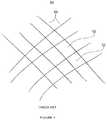
- FIG. 1shows an original or initial image 50 with regions 52 defined by strokes or lines 54 .
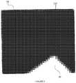
- FIG. 2shows image 50 where a flood fill operation on the regions 52 in FIG. 1 has produced corresponding filled regions 72 .
- Flood fillingis an important technique in two-dimensional computer graphics and has many uses such as coloring the cells of 2D cartoon characters, changing the color of a region in a photographic image, etc.
- a flood fillmay also be applied to a three-dimensional surface, but the calculation is usually two-dimensional.
- Most imaging programssuch as Adobe Photoshop, Painter, and GIMP, have a user tool for performing a flood fill operation. Typically, these tools allow a user to click a point on an image (a seed point) causing a surrounding patch or region of like-colored pixels to be filled with the user's choice of color.
- the regions 52were originally light colored patches bounded by dark colored pixels of the lines 54 (as discussed later, the dashed rectangular region 76 is shown blown-up in FIG. 3 ). After being flood filled, the same regions 52 (seen as regions 72 in FIGS. 2 / 3 ) exhibit the new fill color up to the pixels of the lines 54 that delimit the regions 52 / 72 .
- Flood filling a patch or region of an image with a fill color, fill image, fill function, fill pattern, etc.has usually entailed identifying contiguous pixels that have a same or similar color, and filling that region by setting its pixels to the fill color, Typically, the mutually contiguous pixels in the fill region have an initial color close to or the same as a given base color, usually referred to as a seed color. A color that is “close” may vary from the seed color by less than a specified tolerance. For identifying a fill region, there are many algorithms, most of which simply mark candidate pixels as being “in” or “out” of the region without performing any anti-aliasing.
- a well-known flood filling techniqueis Alvy Ray Smith's tint fill algorithm (ACM Siggraph Proceedings, August 1979). Many flood-filling techniques are similar to Alvy Ray Smith's technique, which usually starts with an array of pixels (an image), a seed color (usually the color of the start pixel), and a destination fill color (the new color being filled in). Starting at the start pixel and working outward, neighboring pixels are recursively considered and added to the region if their color matches or approximates the seed color. The pixels added to the region are set to the fill color.
- Anti-aliasinghas been used to smooth the meeting of these differing colors, for example by applying a blur to the fill region (or to a mask of the fill region).
- anti-aliasingit can help to think of an image as a discrete sampling, or “discretization”, of actual or hypothetical continuous colors.
- anti-aliasingsmoothes the discretization of an image by padding pixels with intermediate colors.
- anti-aliasinghas been computed by performing a flood fill type operation to create a “mask” image of the fill region, applying a slight blur to that mask, and then blending a color into the target image via the mask image.
- FIG. 3shows problems that can occur with prior art anti-aliased flood filling.
- FIG. 3is a blow-up of dashed rectangular region 76 in FIG. 2 .
- pixelssuch as pixel 90 carry shades of the original background color 92 into the filled regions 72 , creating a haloing effect.
- a flood fillis often blurred to emulate anti-aliasing, but insufficient blurring creates jagged edges, and too much blurring creates soft edges and haloes as in FIG. 3 .
- artifacts from anti-aliased flood fillinghave not been automatically correctable or avoidable.
- a candidate pixelcan be included in the region based on a color of the pixel and also a color of a neighbor of the pixel.
- the inclusion basismay be a color distance between a seed color and the points, and a color distance between the seed color and the point's neighbor. Points in the region may be weighted according to their color distance relative to the seed color, where the color distance can also take into account alpha values.
- Flood fillingmay be anti-aliased by assigning alpha values to pixels in gaps between corners of the fill region, where an alpha value may be proportional to a point's contribution to the gap. Dimples in a fill region may be tested for and used to determine which of two flood fill algorithms to use.
- FIG. 1shows an original or initial image with regions defined by strokes or lines.
- FIG. 2shows an image where a flood fill operation on the regions in FIG. 1 has produced corresponding filled regions.
- FIG. 3shows problems that can occur with prior art anti-aliased flood filling.
- FIG. 4shows filled regions resulting from applying new flood fill techniques to the original image in FIG. 1 .
- FIG. 5shows a blow-up of the dashed rectangular area that is shown in both FIG. 4 .
- FIG. 6shows an overview of a combined approach for performing a flood fill operation.
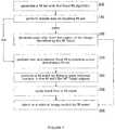
- FIG. 7shows detail of a hybrid approach for performing a flood fill operation.
- FIG. 8shows a first flood fill algorithm
- FIG. 9shows the inclusion test or stopping criteria of the flood fill algorithm shown in FIG. 8 .
- FIG. 10shows a color distance calculator
- FIG. 11shows a fill mask value calculator
- FIG. 12shows a potential dimple to be tested in a flood fill result of the first flood fill algorithm or any other flood fill algorithm.
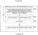
- FIG. 13shows a dimple test applicable to a fill region or fill mask.
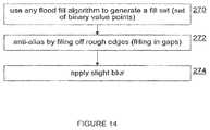
- FIG. 14shows a second anti-aliased flood fill algorithm.
- FIG. 15shows a gap or rough edges.
- FIG. 16shows an algorithm for filing off rough edges.
- FIG. 17shows gaps for filling.
- FIG. 18shows stepwise results of a gap-filling algorithm.
- a “color”, or “color value”is an n-dimensional value indicating the perceived color of a point or pixel. Colors can be defined in RGBA format, which is a 4-dimensional value where the dimensions refer to the intensity of red, green, blue, and opacity (alpha) of the color respectively. As used herein, “color” or “color value” can be in any color space RGB, HSV, CMYK, etc.
- a “color distance”is a value, preferably normalized, indicating various measures of the difference between two colors.
- a color distance between two colorscan indicate if the two colors are identical (e.g. a color distance of 0.0).
- a color distancecan also indicate if two colors are completely different (e.g. a color distance of 1.0).
- Color distanceis preferably represented as a floating point value between 0.0 and 1.0 but can also be represented as fixed point values of any precision—i.e. 8 bit fixed point 0 to 255, or 16 bit fixed point—0 to 65535. An 8 bit fixed point may be adequate in typical image processing applications.
- a “fill mask”is a two-dimensional array or set of single channel values (e.g. 8 bit points representing 0.0 to 1.0) and usually of the same size or color channel depth as the input image being processed. Points in the fill mask contain normalized values indicating the amount that the corresponding image point will be modified by the flood fill operation.
- a “fill set”is a set of points for the image that will be modified by a flood fill operation, usually corresponding to the non-zero pixels in a fill mask.
- a “seed point”is a point in a specific image, usually given by the user to use as the starting point for a flood fill operation.
- a seed pointcan also be algorithmically determined, for example by looking for a point with a color close to the average color of a neighborhood of points. The seed point is usually sure to be included in the fill set and is also the point with which other points in the fill set will be directly or indirectly contiguous with.
- a “seed color”is a color of a seed point in an image to be processed. Although it is possible to start a flood fill operation with a point that is not identical to the seed color (e.g. it may be within a range), usually the seed color will be the initial color of the seed point.
- a “tolerance”is a value, usually normalized, that can be used when generating a fill set to indicate the largest distance between a color and the seed color that will be considered equivalent to a color distance indicating equivalence (e.g. a color distance of 0.0).
- FIGS. 2 and 3show results from a prior art flood fill operation applied to the original image 50 .
- FIG. 4shows filled regions 112 resulting from applying new flood fill techniques to the same original image 50 in FIG. 1 .
- the filled regions 112correspond to regions 52 and can be compared to the corresponding prior art filled regions 72 in FIGS. 2 and 3 .
- FIG. 5shows a blow-up of the dashed rectangular area 76 that is shown in both FIGS. 2 and 4 .
- FIG. 6shows an overview of a combined or hybrid approach for performing a flood fill operation.
- the hybrid approachinvolves first applying 120 a first flood fill algorithm, then testing 122 whether the first flood fill algorithm fails or produces an acceptable flood fill result, and applying 124 a second flood fill technique if the testing 122 indicates that the first flood fill algorithm fails or produces inferior results.
- the new first flood fill algorithm described hereinworks well on certain types of images, but can fail on others. However, failure of the first technique can be tested for. If failure is detected, the new second flood fill technique is used instead.
- the second algorithmworks well on all images, but generally not as well on images preferred by the first algorithm (e.g. pencil sketches, etc.)
- FIG. 7shows detail of a hybrid or two-algorithm approach for performing a flood fill operation.
- the processstarts by generating 140 a fill set with a first flood fill algorithm.
- the success or effectiveness of the first flood fill algorithmis tested 142 to check for dimples in the fill set generated by step 140 . If the first flood fill algorithm passes the dimple test 142 , then the seed color is the deblended 146 from the region of the image identified by the fill mask.
- the deblending 146may be performed according to various techniques described in the related patent application referenced above. If the dimple test 142 fails, then the results of the first algorithm may be discarded, and a non anti-aliased flood fill is performed 148 to produce a non anti-aliased fill set.
- the fill set from step 148is used to produce a fill mask by filling in 150 gaps between corners in the fill set.
- the fill mask produced by step 150is slightly blurred 152 .
- a target coloror image, function, etc. is blended into the fill region of the image according to be values of the fill mask produced by either step 146 or step 152 .
- the first flood fill algorithm mentioned abovehas similarities with Alvy Ray Smith's tint fill algorithm but with new aspects relating to color distance measurement, stopping criteria, and anti-aliasing.
- This first algorithmworks well on pencil sketches, line drawings, cartoon figures, etc., but can fail on airbrushed images and photographs. That is to say, the algorithm works well when there are abrupt or steep color differences.
- the test to determine whether the first algorithm failedcan be characterized as looking for dimples. More specifically, the test involves looking for pixels in the fill mask or region (or an approximation thereof) that are different from both neighboring pixels in the vertical or horizontal direction.
- the second flood fill algorithmhas similarities to standard approaches used by various image processing and editing applications, but with new aspects related to how anti-aliasing is performed, namely generating a mask image and filling in areas around rough edges (in effect visually “filing off” the rough edges) and then slightly blurring the so-filed mask.
- the maskis then used to blend in a color (or other image) into the target image.
- the stopping criteriatells the algorithm when to stop searching for pixels in the fill area around the starting pixel.
- a strict stopping criteriacan be used to identify the region. With this approach, pixels are determined to be either in the region or not in the region. But this stopping criteria approach can cause the fill region to have jagged edges.
- Another approachis to test a degree to which a pixel is “in” the region based on its color distance, but this can cause the fill region to have soft blurry edges.
- a stopping criteriaa criteria to determine which pixels to include in the fill set/mask/region
- a color distance measurementpreferably a tint fill type of algorithm
- an anti-aliasing calculationare preferably all used in a first flood fill algorithm (preferably a tint fill type of algorithm). This first algorithm works well with certain types of images.
- anti-aliasingcan be done at the current point; the pixel's contribution is known and the stop criteria creates the anti-alias effect.
- FIG. 8shows a first flood fill algorithm.
- the first flood fill algorithmstarts with an input image to which the flood fill algorithm is applied, a seed point in the image, and a tolerance.
- the algorithmproduces a fill mask that can be used to flood fill a color at the end of the overall flood fill operation, for example at step 154 in FIG. 7 .
- a fill maskis initialized 170 by setting its elements to zero.
- a seed coloris obtained 172 , for example by using the color value of a seed point selected by a user.
- a fill setis initialized 174 to contain the seed point.
- An inclusion testis applied 176 to each neighbor of the seed point and neighbors are added to the fill set accordingly. The inclusion test or stopping criteria is discussed further below with reference to FIG. 9 .
- For 178 each point added to the fill set, a corresponding fill mask valueis determined 180 using a fill mask value calculation. The fill mask calculation is discussed further below with reference to FIG. 11 . Neighbors of the current point are identified 182 by applying 176 the inclusion test to each neighbor that is not in the fill set.
- Identified neighborsare added 184 to the fill set. The process continues until 186 there are no points left to check.
- the resultis a fill mask with elements that can vary over a range such as from 0 to 255 or 0.0 to 1.0; any range between any two numbers is sufficient.
- FIG. 9shows the inclusion test or stopping criteria of the flood fill algorithm shown in FIG. 8 .
- the teststarts with a seed color, a point color that is the color of the point being considered for inclusion (for purposes of this test, the current point and its color are synonymous), a neighbor color that is the color of a point or pixel neighboring the point being tested, and a tolerance.
- the inclusion testdetermines 200 the current point's color distance—the color distance between the seed color and the current point color—using a color distance calculator, which is discussed below with reference to FIG. 10 .
- the inclusion testdetermines 202 the neighbor point's color distance—the color distance between the seed color and the neighbor color—using the color distance calculator.
- the two color distances from steps 200 and 202are compared to determine 204 if the current point's color distance is less than the tolerance. When it is determined 204 that the current point's color distance is less than the tolerance, true is returned. Conversely, when it is determined 204 that the current point's color distance is not less than the tolerance, then: false is returned when the neighbor's color distance is 206 less than the tolerance; and true is returned when the neighbor's color distance is 206 not less than the tolerance.
- the inclusion test in FIG. 9is applied 176 to the current point and the current point is added to the fill set according to the true/false value returned by the inclusion test. The added point is in turn recursively processed.
- the flood fill algorithm discussed above, and in particular the stop/inclusion criteriacan also be understood by the following explanation. If the image is considered as an array of heights that are color distances from the seed color, then going across a stroke or line the height goes up to a peak around the center of the line and then back down on the other side. It is desirable to flood fill up to the center or peak of the line. But one line or edge can be fainter than another. Using a straight tolerance will not lead to the center of each line; some lines would have halos. By using a stopping or inclusion criteria that looks at neighbors of a point being considered for inclusion, it is possible to include and weight points going “up” the profile of a line and exclude points that are on the downside of a lines color difference profile.
- FIG. 10shows a color distance calculator suitable for use in steps 200 and 202 in FIG. 9 .
- the color distance calculator in FIG. 10starts with two input colors, in RGBA format, for example, and outputs a number from 0.0 to 1.0, for example.
- a distance between each channel of the two input colorsis calculated 220 , preferably using simple differences (i.e. Manhattan distance).
- An RGB distanceis calculated 222 by adding up the calculated 220 distances of each channel.
- a scaled RGB color distanceis determined 224 by multiplying the calculated 222 RGB distance with the smaller of the two alpha values from the two input colors.
- the final color distanceis set 226 to the larger of (1) the difference between the alphas of the respective input colors, and (2) the determined 224 scaled RGB distance.
- the color distance calculator of FIG. 10has been found, through trial and error, to provide optimal results. However, variations and other means of calculating color distance can be used. Although the Manhattan RGB distance is preferable for step 220 , Euclidean distance can also be used, and though theoretically more precise than a Manhattan distance, it is usually hard to tell the difference. It is significantly beneficial to take the smaller of the two alpha values from the two input colors and multiply by the RGB distance (non-alpha distance) and then choose either that alpha distance or the distance of the scaled RGB depending on which is bigger. Another important aspect of the color distance calculator is that even if two color values are very close in color distance (RGB distance) but very different in terms of their respective opacities, a strong difference in their respective opacities can be more significant than their RGB distance.
- RGB distancecolor distance
- FIG. 11shows a fill mask value calculation.
- fill mask valuesare determined 180 (see FIG. 8 ) using a fill mask value calculator.
- the fill mask value calculator shown in FIG. 11starts with the seed color, the color of the point whose corresponding fill mask value is currently being calculated, and the tolerance.
- the color distance between the seed color and the point coloris calculated 230 using the color distance calculator.
- the calculatorreturns 236 a value of 1.0.
- the calculatorreturns 236 a value of 1.0 when the current point's color distance is 234 not strictly greater than the neighbor color's distance, and returns 238 value 1.0 minus the color distance when the current point's color distance is 234 strictly greater than the neighbor color's distance.
- inclusion testwhen testing if a point is to be included (inclusion test), not only is the algorithm looking at the current pixel, but it is also looking at the neighbor in the direction it is going, which handles edge conditions. The fill value is going to be based on that also.
- the algorithmtakes the seed color, point color, and tolerance, and if the color distance is smaller than the tolerance, the color distance is used, otherwise 1.0 minus the color distance is used.
- the first flood fill algorithm discussed aboveworks well as a compliment to a second flood fill algorithm (discussed below), the first flood fill algorithm can also stand on its own.
- anti-aliased flood fillsare crisp and free of artifacts, which has not previously been accomplished.
- the first algorithmmay not produce satisfactory results, such as when the input image has smooth gradations of color as in photographs or airbrush drawings. As discussed below, the undesirable results can be recognized.
- FIG. 12shows a potential dimple 240 to be tested in a flood fill result of the first flood fill algorithm or any other flood fill algorithm.
- test point 240is compared to its vertical neighbors 242 and its horizontal neighbors 244 .
- FIG. 13shows a dimple test applicable to a fill region or fill mask. Pixels in the fill mask or the fill region are iterated over, and for a current pixel: if 250 both vertical neighbors 242 of the current pixel 240 are different, or if both horizontal neighbors 244 of the current pixel 240 are different, then a dimple is found and a dimple count is incremented 252 . When no more pixels remain 254 in the fill mask/region, the test returns a pass or fail according to the dimple count.
- the return valuecan be according to a simple threshold dimple count, a ratio of dimples, a density of dimples, etc. The more dimples found, the more likely it is that there is a failure of the first flood fill algorithm or whatever other algorithm is being tested.
- the dimple testis checking the border of the fill mask, and can be optimized by testing only on or near the border.
- the testis inexpensive so this optimization is not usually necessary or preferable.
- the testalso stands alone as a test capable of efficiently checking for border noise.
- Previous techniquesflood fill by generating a single channel image, or mask, of the pixels to be filled, and then they apply a convolution filter or a blur to soften the edges.
- the blurred maskis then used to scale a color or image and then blend that on top.
- artifactssuch as halos or a jaggedness effect are common.
- the jaggedness effectcan be reduced with increased blurring, but the edges then appear too soft and greater or larger haloing artifacts appear.
- an imageis a discrete sampling, or “discretization” of continuous colors.
- a pixelcan be thought of as a representation or sample of some real value at a particular point; a grid of pixels is not really a precisely subdivided grid, but rather an arrangement of points (centers of a pixel's square) that have space between them. So even a location near a square's border is really a mix of the nearby pixel centers. In sum, pixels are not really squares of color. But, pixels can be treated as such so information can be interpolated.
- FIG. 14shows a second anti-aliased flood fill algorithm. Any flood fill algorithm is used to generate 270 a fill set or a fill mask with values of either 0.0 or 1.0. Gaps along the edge of the fill mask are filled 272 . This can also be thought of as filing off the rough corners of the fill mask. A slight blur is then applied 274 to the fill mask to create the anti-aliased flood fill region.
- FIG. 15shows a gap (points/squares with both horizontal and vertical lines) between rough edges (points 280 , seen as bold-lined squares).
- Checkered pointsrepresent points or pixels in the fill mask. Corners of two fill mask pixels 280 are “rough edges”.
- a hypothetical line 282passes through the corners, creating hypothetical regions 284 near the fill set (horizontal lines) and also vertically striped regions 286 on the other side of the line 282 .
- FIG. 16shows an algorithm for filing off 272 the rough edges 280 .
- any flood fill algorithmcan be used with a seed point and a tolerance to generate 290 a fill mask (0.0 s and 1.0 s).
- the fill maskis parsed or walked to find pixels with corners such as pixels 280 .
- the pixelsPreferably, the pixels have one-pixel width gaps.
- the points falling on the hypothetical line 282 between the points 280are filled 272 by setting an opacity of each according to a ratio of areas of the portions on opposing sides of the line 282 .
- pixels in the gap between the corner pixels 280will be assigned an opacity or transparency according to how deep or shallow its portion of the gap is; deeper pixels will be assigned higher opacities.
- pixelsare assigned opacity according to a ratio of their horizontally-striped region to their vertically-striped region.
- a blurmay be applied to the filed-off fill mask, the blur may not be necessary. If a blur is applied after the filing, a 1 to 1.5 pixel radius is preferable.
- the bluris a weighted average blur over a 3 ⁇ 3 pixel neighborhood. That is, for each pixel in the target taking a weighted average, preferably over a 1.5 pixel radius, performs image a Gaussian blur.
- FIG. 17shows gaps for filling with alpha values.
- Dark squares in grid 300depict pixels in a fill region.
- the short dashed linesresult from a horizontal pass, and the long dashed lines result from a vertical pass. These lines correspond to line 282 in FIG. 15 .
- the gap filling algorithmscans up and down, left and right, to find runs of pixels.
- a run of pixelsstarts at or near a corner and ends at or near a pixel of the fill region.
- gapsare one pixel wide.
- a distinguishing characteristic of a gapis that it does not necessarily go from one corner to another, but rather may end against a flat part of the border of the fill region, which may be substantially longer than one pixel or the height of the gap.
- a gapcan run from a corner to an interior point of a side.
- a cornercan be a corner such as would be found by a convex hull of the fill region, but a corner can also be interior to a convex hull wrapping, as seen by corner 304 . That is to say, the algorithm scans for locally outer corners.
- the gapsmay be understood as spanning from a corner to another corner, or from a corner to a side of the fill region.
- the gapsmay also be defined as portions of a theoretical layer around the fill region. Taking a given fill region, there is one pixel wide layer of pixels surrounding the fill region. Pixels in the gap portions of the layer are given alpha values as discussed above.
- pixels such as pixel 306are in two gaps, such as the two gaps defined by or corresponding to lines 302 .
- the alpha value assigned to pixel 306is preferably the larger of the value according to either line 302 .
- the alpha value according to horizontal gap/line 302would be used.
- An average valuemay also be used.
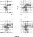
- FIG. 18shows stepwise results of a gap-filling algorithm. Starting 320 with a fill region, a layer of pixels is found 322 . Corner pixels of the layer are marked 324 . Finally, pixels intersected by dashed lines are filled in proportion to their positions along the gap (i.e. their contribution to the triangles defined by the dashed lines and two sides of the fill region.
- the gap-filling algorithmcan be applied independently to a defined patch, whether the patch is predefined, derived from a flood fill, or otherwise provided.
- the tolerances discussed aboveare not necessary, and can be obviated by setting its value to zero, thus requiring color equivalence.
- the stopping criteria, the color distance calculator, the fill mask value calculator, and other aspects discussed aboveeach have their own advantages but also work well when combined.
- the filing off of rough edgescan be applied to any boundary whether from a flood fill operation or not.
- the dimple testcan test for noise in any context.
- a candidate pixelcan be included in the region based on a color of the pixel and also a color of a neighbor of the point.
- the inclusion basismay be a color distance between a seed color and the points, and a color distance between the seed color and the point's neighbor.
- Points in the regionmay be weighted according to their color distance relative to the seed color, where the color distance can also take into account alpha values.
- Flood fillingmay be anti-aliased by assigning alpha values to pixels in gaps between corners of the fill region, where an alpha value may be proportional to a point's contribution to the gap. Dimples in a fill region may be tested for and used to determine which of two flood fill algorithms to use.
Landscapes
- Physics & Mathematics (AREA)
- General Physics & Mathematics (AREA)
- Engineering & Computer Science (AREA)
- Theoretical Computer Science (AREA)
- Image Processing (AREA)
Abstract
Description
Claims (9)
Priority Applications (1)
| Application Number | Priority Date | Filing Date | Title |
|---|---|---|---|
| US14/876,738US10803629B2 (en) | 2004-10-22 | 2015-10-06 | Graphics processing method and system |
Applications Claiming Priority (3)
| Application Number | Priority Date | Filing Date | Title |
|---|---|---|---|
| US10/969,878US8744184B2 (en) | 2004-10-22 | 2004-10-22 | Graphics processing method and system |
| US12/004,042US9153052B2 (en) | 2004-10-22 | 2007-12-20 | Graphics processing method and system |
| US14/876,738US10803629B2 (en) | 2004-10-22 | 2015-10-06 | Graphics processing method and system |
Related Parent Applications (1)
| Application Number | Title | Priority Date | Filing Date |
|---|---|---|---|
| US12/004,042DivisionUS9153052B2 (en) | 2004-10-22 | 2007-12-20 | Graphics processing method and system |
Publications (2)
| Publication Number | Publication Date |
|---|---|
| US20160098845A1 US20160098845A1 (en) | 2016-04-07 |
| US10803629B2true US10803629B2 (en) | 2020-10-13 |
Family
ID=36205780
Family Applications (7)
| Application Number | Title | Priority Date | Filing Date |
|---|---|---|---|
| US10/969,878Active2027-12-21US8744184B2 (en) | 2004-10-22 | 2004-10-22 | Graphics processing method and system |
| US12/004,042Expired - LifetimeUS9153052B2 (en) | 2004-10-22 | 2007-12-20 | Graphics processing method and system |
| US12/352,797AbandonedUS20090122071A1 (en) | 2004-10-22 | 2009-01-13 | Graphics processing method and system |
| US12/352,801Expired - LifetimeUS8805064B2 (en) | 2004-10-22 | 2009-01-13 | Graphics processing method and system |
| US12/352,806AbandonedUS20090122078A1 (en) | 2004-10-22 | 2009-01-13 | Graphics processing method and system |
| US12/352,804AbandonedUS20090122077A1 (en) | 2004-10-22 | 2009-01-13 | Graphics processing method and system |
| US14/876,738Expired - LifetimeUS10803629B2 (en) | 2004-10-22 | 2015-10-06 | Graphics processing method and system |
Family Applications Before (6)
| Application Number | Title | Priority Date | Filing Date |
|---|---|---|---|
| US10/969,878Active2027-12-21US8744184B2 (en) | 2004-10-22 | 2004-10-22 | Graphics processing method and system |
| US12/004,042Expired - LifetimeUS9153052B2 (en) | 2004-10-22 | 2007-12-20 | Graphics processing method and system |
| US12/352,797AbandonedUS20090122071A1 (en) | 2004-10-22 | 2009-01-13 | Graphics processing method and system |
| US12/352,801Expired - LifetimeUS8805064B2 (en) | 2004-10-22 | 2009-01-13 | Graphics processing method and system |
| US12/352,806AbandonedUS20090122078A1 (en) | 2004-10-22 | 2009-01-13 | Graphics processing method and system |
| US12/352,804AbandonedUS20090122077A1 (en) | 2004-10-22 | 2009-01-13 | Graphics processing method and system |
Country Status (1)
| Country | Link |
|---|---|
| US (7) | US8744184B2 (en) |
Families Citing this family (30)
| Publication number | Priority date | Publication date | Assignee | Title |
|---|---|---|---|---|
| US8744184B2 (en) | 2004-10-22 | 2014-06-03 | Autodesk, Inc. | Graphics processing method and system |
| US8379101B2 (en)* | 2009-05-29 | 2013-02-19 | Microsoft Corporation | Environment and/or target segmentation |
| TWI489860B (en)* | 2011-11-08 | 2015-06-21 | Novatek Microelectronics Corp | Three-dimension image processing method and a three-dimension image display apparatus applying the same |
| US8952979B2 (en)* | 2012-09-19 | 2015-02-10 | Autodesk, Inc. | Wave fill |
| US8902238B2 (en) | 2012-10-15 | 2014-12-02 | Intel Corporation | Parallel flood-fill techniques and architecture |
| CN105096353B (en)* | 2014-05-05 | 2020-02-11 | 腾讯科技(深圳)有限公司 | Image processing method and device |
| US9350924B2 (en) | 2014-08-25 | 2016-05-24 | John G. Posa | Portable electronic devices with integrated image/video compositing |
| JP6992005B2 (en) | 2016-01-18 | 2022-01-13 | アドバンスト・マイクロ・ディバイシズ・インコーポレイテッド | Performing anti-aliasing operations in computing systems |
| US11179926B2 (en) | 2016-12-15 | 2021-11-23 | General Electric Company | Hybridized light sources |
| US10430987B1 (en) | 2017-06-09 | 2019-10-01 | Snap Inc. | Annotating an image with a texture fill |
| CN108198128B (en)* | 2017-12-12 | 2021-12-03 | 北京美摄网络科技有限公司 | Method and device for alpha channel boundary corrosion |
| CN109117542B (en)* | 2018-08-06 | 2023-03-24 | 深圳一起秀信息科技有限公司 | Parquet importing method based on convolution algorithm |
| US11328457B2 (en) | 2019-09-11 | 2022-05-10 | Microsoft Technology Licensing, Llc | System and method for tinting of computer-generated object(s) |
| US11076151B2 (en) | 2019-09-30 | 2021-07-27 | Ati Technologies Ulc | Hierarchical histogram calculation with application to palette table derivation |
| US11915337B2 (en) | 2020-03-13 | 2024-02-27 | Advanced Micro Devices, Inc. | Single pass downsampler |
| US11707883B2 (en) | 2020-11-20 | 2023-07-25 | General Electric Company | Foil interaction device for additive manufacturing |
| US11010943B1 (en) | 2020-12-18 | 2021-05-18 | Ivan Bajic | Method and system for digital coloring or segmenting of multi-color graphics |
| US11865780B2 (en) | 2021-02-26 | 2024-01-09 | General Electric Company | Accumalator assembly for additive manufacturing |
| US11954798B2 (en)* | 2021-04-22 | 2024-04-09 | Faro Technologies, Inc. | Automatic selection of a region in a three-dimensional (3D) point cloud |
| US11951679B2 (en) | 2021-06-16 | 2024-04-09 | General Electric Company | Additive manufacturing system |
| US11731367B2 (en) | 2021-06-23 | 2023-08-22 | General Electric Company | Drive system for additive manufacturing |
| US11958249B2 (en) | 2021-06-24 | 2024-04-16 | General Electric Company | Reclamation system for additive manufacturing |
| US11958250B2 (en) | 2021-06-24 | 2024-04-16 | General Electric Company | Reclamation system for additive manufacturing |
| US11826950B2 (en) | 2021-07-09 | 2023-11-28 | General Electric Company | Resin management system for additive manufacturing |
| US12370741B2 (en) | 2021-08-13 | 2025-07-29 | General Electric Company | Material deposition assembly for additive manufacturing |
| US12296535B2 (en) | 2021-08-24 | 2025-05-13 | General Electric Company | Attachment structure for additive manufacturing |
| US11813799B2 (en) | 2021-09-01 | 2023-11-14 | General Electric Company | Control systems and methods for additive manufacturing |
| EP4249216A1 (en) | 2022-03-23 | 2023-09-27 | General Electric Company | Systems and methods for additive manufacturing |
| US12403654B2 (en) | 2022-09-30 | 2025-09-02 | General Electric Company | Systems and methods for additive manufacturing |
| CN118735871A (en)* | 2024-06-18 | 2024-10-01 | 宁波锦德五金有限公司 | Transmission wire fittings surface color deviation detection system |
Citations (26)
| Publication number | Priority date | Publication date | Assignee | Title |
|---|---|---|---|---|
| US4947158A (en) | 1987-03-13 | 1990-08-07 | Ricoh Company, Ltd. | Method and apparatus for filling in an inner region of a pattern |
| US5122873A (en) | 1987-10-05 | 1992-06-16 | Intel Corporation | Method and apparatus for selectively encoding and decoding a digital motion video signal at multiple resolution levels |
| US5122872A (en) | 1985-06-20 | 1992-06-16 | Sharp Kabushiki Kaisha | Picture data memory system for storing both black and white and color picture data with different resolutions |
| US5438656A (en) | 1993-06-01 | 1995-08-01 | Ductus, Inc. | Raster shape synthesis by direct multi-level filling |
| US5495429A (en) | 1993-02-12 | 1996-02-27 | West Virginia University | Method and apparatus for measuring the color of three dimensional objects |
| US5872902A (en)* | 1993-05-28 | 1999-02-16 | Nihon Unisys, Ltd. | Method and apparatus for rendering of fractional pixel lists for anti-aliasing and transparency |
| US6134345A (en) | 1998-08-28 | 2000-10-17 | Ultimatte Corporation | Comprehensive method for removing from an image the background surrounding a selected subject |
| US6134346A (en) | 1998-01-16 | 2000-10-17 | Ultimatte Corp | Method for removing from an image the background surrounding a selected object |
| US6167166A (en) | 1998-03-23 | 2000-12-26 | Xerox Corporation | Method to enable the recognition and rendering of antialiased images |
| US6228703B1 (en) | 1998-12-10 | 2001-05-08 | United Microelectronics, Corp. | Method of fabricating mixed-mode semiconductor device having a capacitor and a gate |
| US20020101435A1 (en)* | 2000-08-23 | 2002-08-01 | Nobuo Sasaki | Apparatus and method for rendering antialiased image |
| US20030147100A1 (en) | 2000-05-03 | 2003-08-07 | Andersen Hans Jorgen | Method of segmentation of a digital image and a method of controlling an implement |
| US20030174872A1 (en) | 2001-10-15 | 2003-09-18 | Insightful Corporation | System and method for mining quantitive information from medical images |
| US20040042682A1 (en) | 2002-08-30 | 2004-03-04 | Charles Jia | Method and apparatus for automatic removal of optical artifacts in scanning |
| US6738154B1 (en) | 1997-01-21 | 2004-05-18 | Xerox Corporation | Locating the position and orientation of multiple objects with a smart platen |
| US20040130548A1 (en) | 2003-01-07 | 2004-07-08 | Hux William A | Voxel center smoothing |
| US20040130546A1 (en) | 2003-01-06 | 2004-07-08 | Porikli Fatih M. | Region growing with adaptive thresholds and distance function parameters |
| US20040145599A1 (en) | 2002-11-27 | 2004-07-29 | Hiroki Taoka | Display apparatus, method and program |
| US20050007381A1 (en)* | 2003-07-07 | 2005-01-13 | Dongren Chen | Graphic engine for handling sub-pixel regions in a resource-constrained device |
| US20050168476A1 (en) | 2003-10-30 | 2005-08-04 | Sensable Technologies, Inc. | Apparatus and methods for stenciling an image |
| US20050206657A1 (en)* | 2004-03-17 | 2005-09-22 | Arcas Blaise A Y | Methods and apparatus for navigating an image |
| US20050226502A1 (en) | 2004-03-31 | 2005-10-13 | Microsoft Corporation | Stylization of video |
| US6982723B1 (en) | 1998-08-30 | 2006-01-03 | Gmd-Forschungszentrum Informationstechnik Gmbh | Method and apparatus for eliminating unwanted steps at edges in graphic representations in the line raster |
| US20060044323A1 (en) | 2004-08-27 | 2006-03-02 | Alias Systems | Transparency and/or color processing |
| US7054503B2 (en) | 2001-02-23 | 2006-05-30 | Seiko Epson Corporation | Image processing system, image processing method, and image processing program |
| US20090122077A1 (en) | 2004-10-22 | 2009-05-14 | Autodesk, Inc. | Graphics processing method and system |
Family Cites Families (2)
| Publication number | Priority date | Publication date | Assignee | Title |
|---|---|---|---|---|
| US6288703B1 (en)* | 1996-11-25 | 2001-09-11 | Ultimatte Corporation | Method for removing from an image the background surrounding a selected subject by generating candidate mattes |
| US7302904B2 (en)* | 1997-09-01 | 2007-12-04 | Peter Robert Burns | Ground anchors with compression plates |
- 2004
- 2004-10-22USUS10/969,878patent/US8744184B2/enactiveActive
- 2007
- 2007-12-20USUS12/004,042patent/US9153052B2/ennot_activeExpired - Lifetime
- 2009
- 2009-01-13USUS12/352,797patent/US20090122071A1/ennot_activeAbandoned
- 2009-01-13USUS12/352,801patent/US8805064B2/ennot_activeExpired - Lifetime
- 2009-01-13USUS12/352,806patent/US20090122078A1/ennot_activeAbandoned
- 2009-01-13USUS12/352,804patent/US20090122077A1/ennot_activeAbandoned
- 2015
- 2015-10-06USUS14/876,738patent/US10803629B2/ennot_activeExpired - Lifetime
Patent Citations (31)
| Publication number | Priority date | Publication date | Assignee | Title |
|---|---|---|---|---|
| US5122872A (en) | 1985-06-20 | 1992-06-16 | Sharp Kabushiki Kaisha | Picture data memory system for storing both black and white and color picture data with different resolutions |
| US4947158A (en) | 1987-03-13 | 1990-08-07 | Ricoh Company, Ltd. | Method and apparatus for filling in an inner region of a pattern |
| US5122873A (en) | 1987-10-05 | 1992-06-16 | Intel Corporation | Method and apparatus for selectively encoding and decoding a digital motion video signal at multiple resolution levels |
| US5495429A (en) | 1993-02-12 | 1996-02-27 | West Virginia University | Method and apparatus for measuring the color of three dimensional objects |
| US5872902A (en)* | 1993-05-28 | 1999-02-16 | Nihon Unisys, Ltd. | Method and apparatus for rendering of fractional pixel lists for anti-aliasing and transparency |
| US5438656A (en) | 1993-06-01 | 1995-08-01 | Ductus, Inc. | Raster shape synthesis by direct multi-level filling |
| US6738154B1 (en) | 1997-01-21 | 2004-05-18 | Xerox Corporation | Locating the position and orientation of multiple objects with a smart platen |
| US6134346A (en) | 1998-01-16 | 2000-10-17 | Ultimatte Corp | Method for removing from an image the background surrounding a selected object |
| US6167166A (en) | 1998-03-23 | 2000-12-26 | Xerox Corporation | Method to enable the recognition and rendering of antialiased images |
| US6134345A (en) | 1998-08-28 | 2000-10-17 | Ultimatte Corporation | Comprehensive method for removing from an image the background surrounding a selected subject |
| US6982723B1 (en) | 1998-08-30 | 2006-01-03 | Gmd-Forschungszentrum Informationstechnik Gmbh | Method and apparatus for eliminating unwanted steps at edges in graphic representations in the line raster |
| US6228703B1 (en) | 1998-12-10 | 2001-05-08 | United Microelectronics, Corp. | Method of fabricating mixed-mode semiconductor device having a capacitor and a gate |
| US20030147100A1 (en) | 2000-05-03 | 2003-08-07 | Andersen Hans Jorgen | Method of segmentation of a digital image and a method of controlling an implement |
| US20020101435A1 (en)* | 2000-08-23 | 2002-08-01 | Nobuo Sasaki | Apparatus and method for rendering antialiased image |
| US7054503B2 (en) | 2001-02-23 | 2006-05-30 | Seiko Epson Corporation | Image processing system, image processing method, and image processing program |
| US20030174872A1 (en) | 2001-10-15 | 2003-09-18 | Insightful Corporation | System and method for mining quantitive information from medical images |
| US20040042682A1 (en) | 2002-08-30 | 2004-03-04 | Charles Jia | Method and apparatus for automatic removal of optical artifacts in scanning |
| US20040145599A1 (en) | 2002-11-27 | 2004-07-29 | Hiroki Taoka | Display apparatus, method and program |
| US20040130546A1 (en) | 2003-01-06 | 2004-07-08 | Porikli Fatih M. | Region growing with adaptive thresholds and distance function parameters |
| US20040130548A1 (en) | 2003-01-07 | 2004-07-08 | Hux William A | Voxel center smoothing |
| US20050007381A1 (en)* | 2003-07-07 | 2005-01-13 | Dongren Chen | Graphic engine for handling sub-pixel regions in a resource-constrained device |
| US20050168476A1 (en) | 2003-10-30 | 2005-08-04 | Sensable Technologies, Inc. | Apparatus and methods for stenciling an image |
| US20050206657A1 (en)* | 2004-03-17 | 2005-09-22 | Arcas Blaise A Y | Methods and apparatus for navigating an image |
| US20050226502A1 (en) | 2004-03-31 | 2005-10-13 | Microsoft Corporation | Stylization of video |
| US20060044323A1 (en) | 2004-08-27 | 2006-03-02 | Alias Systems | Transparency and/or color processing |
| US7302094B2 (en) | 2004-08-27 | 2007-11-27 | Autodesk, Inc. | Transparency and/or color processing |
| US20090122077A1 (en) | 2004-10-22 | 2009-05-14 | Autodesk, Inc. | Graphics processing method and system |
| US20090122071A1 (en) | 2004-10-22 | 2009-05-14 | Autodesk, Inc. | Graphics processing method and system |
| US20090122078A1 (en) | 2004-10-22 | 2009-05-14 | Autodesk, Inc | Graphics processing method and system |
| US8744184B2 (en) | 2004-10-22 | 2014-06-03 | Autodesk, Inc. | Graphics processing method and system |
| US9153052B2 (en) | 2004-10-22 | 2015-10-06 | Autodesk, Inc. | Graphics processing method and system |
Non-Patent Citations (26)
| Title |
|---|
| Fathi, et al., "A New Fuzzy Based Floor-Fill Algorithm for 3 D NMR Brain Segmentation", IEEE SMC '99 Conference Proceedings, 1999 IEEE International Conference on Systems, Man, and Cybernetics, vol. 4, 1999, pp. 881-885. |
| Final Office Action dated Apr. 19, 2013 for copending U.S. Appl. No. 12/352,801. |
| Final Office Action dated Aug. 12, 2008 in U.S. Appl. No. 10/969,878. |
| Final Office Action dated Aug. 18, 2011 for copending U.S. Appl. No. 12/352,801. |
| Final Office Action dated Nov. 16, 2009 in U.S. Appl. No. 12/004,042. |
| Final Office Action dated Nov. 4, 2010 issued in co-pending U.S. Appl. No. 12/352,801. |
| Final Office Action dated Oct. 23, 2009 in U.S. Appl. No. 12/352,797. |
| Final Office Action dated Oct. 23, 2009 in U.S. Appl. No. 12/352,804. |
| Final Office Action dated Sep. 29, 2009 in U.S. Appl. No. 10/969,878. |
| Final Office Action dated Sep. 4, 2007 in U.S. Appl. No. 10/969,878. |
| Lauckhart, "System and Method for Interactvely Identifying Regions of a Digital Image", IBM Technical Disclosure Bulletin, Jun. 1, 1996, vol. 39, Issue 6, p. 247-248. |
| Martin et al., "A topology-based filing algorithm", Computer and Graphics, vol. 25, No. 3, 2001, pp. 493-509. |
| Office Action dated Apr. 12, 2007 in U.S. Appl. No. 10/969,878. |
| Office Action dated Apr. 26, 2010 for co-pending U.S. Appl. No. 12/352,801. |
| Office Action dated Aug. 21, 2012 for copending U.S. Appl. No. 12/352,801. |
| Office Action dated Feb. 28, 2011 issued in co-pending U.S. Appl. No. 12/352,801. |
| Office Action dated Jan. 3, 2007 in U.S. Appl. No. 10/969,878. |
| Office Action dated Jan. 9, 2008 in U.S. Appl. No. 10/969,878. |
| Office Action dated Jun. 15, 2009 in U.S. Appl. No. 12/352,806. |
| Office Action dated Jun. 7, 2010 for co-pending U.S. Appl. No. 12/352,797. |
| Office Action dated Mar. 25, 2009 in U.S. Appl. No. 10/969,878. |
| Office Action dated Mar. 30, 2009 in U.S. Appl. No. 12/352,804. |
| Office Action dated Mar. 31, 2009 in U.S. Appl. No. 12/352,797. |
| Office Action dated Mar. 4, 2009 in U.S. Appl. No. 12/004,042. |
| Office Action dated Nov. 26, 2013 for copending U.S. Appl. No. 12/004,042. |
| Porter et al., "Compositing Digital Images", Computer Graphics, vol. 18, No. 3, Jul. 1984, pp. 253-259. |
Also Published As
| Publication number | Publication date |
|---|---|
| US20060087518A1 (en) | 2006-04-27 |
| US20090122071A1 (en) | 2009-05-14 |
| US9153052B2 (en) | 2015-10-06 |
| US20090122077A1 (en) | 2009-05-14 |
| US20090122072A1 (en) | 2009-05-14 |
| US20090122078A1 (en) | 2009-05-14 |
| US20080100640A1 (en) | 2008-05-01 |
| US8805064B2 (en) | 2014-08-12 |
| US8744184B2 (en) | 2014-06-03 |
| US20160098845A1 (en) | 2016-04-07 |
Similar Documents
| Publication | Publication Date | Title |
|---|---|---|
| US10803629B2 (en) | Graphics processing method and system | |
| US7676086B2 (en) | Automatic coloring of pixels exposed during manipulation of image regions | |
| US8422776B2 (en) | Transparency and/or color processing | |
| CA2442603C (en) | Digital composition of a mosaic image | |
| US7557812B2 (en) | Multilevel texture processing method for mapping multiple images onto 3D models | |
| US8374428B2 (en) | Color balancing for partially overlapping images | |
| US9886747B2 (en) | Digital image blemish removal | |
| CA2527053C (en) | Shading computer-generated objects using generalized shading regions | |
| US7542033B2 (en) | Method and program for generating a two-dimensional cartoonish picturization of a three-dimensional object | |
| US20030206652A1 (en) | Depth map creation through hypothesis blending in a bayesian framework | |
| WO2022132289A1 (en) | Method and system for digital coloring or segmenting of multi-color graphics | |
| US7359530B2 (en) | Object-based raster trapping | |
| US8913074B2 (en) | Colorization method and apparatus | |
| Sari et al. | Structure-texture consistent painting completion for artworks | |
| US7190374B2 (en) | Shading polygons from a three-dimensional model | |
| US20040233196A1 (en) | Logic arrangements storage mediums, and methods for generating digital images using brush strokes | |
| Sauvaget et al. | Comics stylization from photographs | |
| CN113012225B (en) | Quick positioning method for minimum circumscribed rectangular frame of material image of color sorter | |
| KR101155227B1 (en) | Apparatus and method for converting image reflecting directional texture information of original image | |
| Arroyo et al. | Stochastic generation of dots for computer aided stippling | |
| Sauvaget et al. | Abstraction of photographs: a comics style approach | |
| Obaid | Moment Based Painterly Rendering Using Connected Color Components |
Legal Events
| Date | Code | Title | Description |
|---|---|---|---|
| AS | Assignment | Owner name:ALIAS SYSTEMS CORP., CANADA Free format text:ASSIGNMENT OF ASSIGNORS INTEREST;ASSIGNORS:AMELINE, IAN R.;BLAIS, ERIC A.;REEL/FRAME:043532/0125 Effective date:20041022 Owner name:AUTODESK, INC., CALIFORNIA Free format text:ASSIGNMENT OF ASSIGNORS INTEREST;ASSIGNOR:ALIAS SYSTEMS CORP.;REEL/FRAME:044102/0142 Effective date:20060125 | |
| STPP | Information on status: patent application and granting procedure in general | Free format text:DOCKETED NEW CASE - READY FOR EXAMINATION | |
| STPP | Information on status: patent application and granting procedure in general | Free format text:NON FINAL ACTION MAILED | |
| STPP | Information on status: patent application and granting procedure in general | Free format text:FINAL REJECTION MAILED | |
| STPP | Information on status: patent application and granting procedure in general | Free format text:ADVISORY ACTION MAILED | |
| STPP | Information on status: patent application and granting procedure in general | Free format text:NON FINAL ACTION MAILED | |
| STPP | Information on status: patent application and granting procedure in general | Free format text:FINAL REJECTION MAILED | |
| STPP | Information on status: patent application and granting procedure in general | Free format text:NOTICE OF ALLOWANCE MAILED -- APPLICATION RECEIVED IN OFFICE OF PUBLICATIONS | |
| STPP | Information on status: patent application and granting procedure in general | Free format text:PUBLICATIONS -- ISSUE FEE PAYMENT RECEIVED | |
| STCF | Information on status: patent grant | Free format text:PATENTED CASE | |
| CC | Certificate of correction | ||
| MAFP | Maintenance fee payment | Free format text:PAYMENT OF MAINTENANCE FEE, 4TH YEAR, LARGE ENTITY (ORIGINAL EVENT CODE: M1551); ENTITY STATUS OF PATENT OWNER: LARGE ENTITY Year of fee payment:4 |