US10801197B2 - Wall assembly having a spacer - Google Patents
Wall assembly having a spacerDownload PDFInfo
- Publication number
- US10801197B2 US10801197B2US15/543,872US201615543872AUS10801197B2US 10801197 B2US10801197 B2US 10801197B2US 201615543872 AUS201615543872 AUS 201615543872AUS 10801197 B2US10801197 B2US 10801197B2
- Authority
- US
- United States
- Prior art keywords
- spacer
- vertical members
- wall assembly
- insulating layer
- layer
- Prior art date
- Legal status (The legal status is an assumption and is not a legal conclusion. Google has not performed a legal analysis and makes no representation as to the accuracy of the status listed.)
- Active
Links
- 125000006850spacer groupChemical group0.000titleclaimsabstractdescription112
- 239000006260foamSubstances0.000claimsdescription72
- -1cementitious boardSubstances0.000claimsdescription41
- 230000004888barrier functionEffects0.000claimsdescription16
- 238000000034methodMethods0.000claimsdescription13
- 229920002396PolyureaPolymers0.000claimsdescription10
- 229920005830Polyurethane FoamPolymers0.000claimsdescription7
- 239000011496polyurethane foamSubstances0.000claimsdescription7
- 230000008878couplingEffects0.000claimsdescription6
- 238000010168coupling processMethods0.000claimsdescription6
- 238000005859coupling reactionMethods0.000claimsdescription6
- 238000009413insulationMethods0.000claimsdescription6
- 239000011120plywoodSubstances0.000claimsdescription5
- 239000011094fiberboardSubstances0.000claimsdescription4
- 238000004519manufacturing processMethods0.000claimsdescription4
- 229910052500inorganic mineralInorganic materials0.000claimsdescription3
- 239000011707mineralSubstances0.000claimsdescription3
- 238000005507sprayingMethods0.000claimsdescription2
- 208000004880PolyuriaDiseases0.000claims2
- 239000011230binding agentSubstances0.000description50
- 239000002245particleSubstances0.000description44
- 229920000642polymerPolymers0.000description33
- 239000000203mixtureSubstances0.000description29
- 229920001577copolymerPolymers0.000description25
- 239000000178monomerSubstances0.000description24
- 239000000463materialSubstances0.000description22
- 230000001070adhesive effectEffects0.000description21
- 239000000853adhesiveSubstances0.000description20
- 239000000565sealantSubstances0.000description16
- 229920002635polyurethanePolymers0.000description15
- 239000004814polyurethaneSubstances0.000description15
- VYPSYNLAJGMNEJ-UHFFFAOYSA-NSilicium dioxideChemical compoundO=[Si]=OVYPSYNLAJGMNEJ-UHFFFAOYSA-N0.000description13
- 239000003063flame retardantSubstances0.000description11
- 238000006116polymerization reactionMethods0.000description11
- PPBRXRYQALVLMV-UHFFFAOYSA-NStyreneChemical compoundC=CC1=CC=CC=C1PPBRXRYQALVLMV-UHFFFAOYSA-N0.000description10
- NIXOWILDQLNWCW-UHFFFAOYSA-Nacrylic acid groupChemical groupC(C=C)(=O)ONIXOWILDQLNWCW-UHFFFAOYSA-N0.000description10
- 238000007720emulsion polymerization reactionMethods0.000description10
- 239000012948isocyanateSubstances0.000description9
- 150000002513isocyanatesChemical class0.000description9
- 229920005989resinPolymers0.000description9
- 239000011347resinSubstances0.000description9
- 229920002554vinyl polymerPolymers0.000description9
- RNFJDJUURJAICM-UHFFFAOYSA-N2,2,4,4,6,6-hexaphenoxy-1,3,5-triaza-2$l^{5},4$l^{5},6$l^{5}-triphosphacyclohexa-1,3,5-trieneChemical compoundN=1P(OC=2C=CC=CC=2)(OC=2C=CC=CC=2)=NP(OC=2C=CC=CC=2)(OC=2C=CC=CC=2)=NP=1(OC=1C=CC=CC=1)OC1=CC=CC=C1RNFJDJUURJAICM-UHFFFAOYSA-N0.000description8
- NIXOWILDQLNWCW-UHFFFAOYSA-MAcrylateChemical compound[O-]C(=O)C=CNIXOWILDQLNWCW-UHFFFAOYSA-M0.000description8
- MHAJPDPJQMAIIY-UHFFFAOYSA-NHydrogen peroxideChemical compoundOOMHAJPDPJQMAIIY-UHFFFAOYSA-N0.000description8
- 239000004793PolystyreneSubstances0.000description8
- 229920002223polystyrenePolymers0.000description8
- 239000004721Polyphenylene oxideSubstances0.000description7
- 239000008186active pharmaceutical agentSubstances0.000description7
- 239000012530fluidSubstances0.000description7
- 239000011521glassSubstances0.000description7
- CIWBSHSKHKDKBQ-JLAZNSOCSA-NAscorbic acidChemical compoundOC[C@H](O)[C@H]1OC(=O)C(O)=C1OCIWBSHSKHKDKBQ-JLAZNSOCSA-N0.000description6
- GWEVSGVZZGPLCZ-UHFFFAOYSA-NTitan oxideChemical compoundO=[Ti]=OGWEVSGVZZGPLCZ-UHFFFAOYSA-N0.000description6
- 239000011449brickSubstances0.000description6
- 239000007795chemical reaction productSubstances0.000description6
- 238000004132cross linkingMethods0.000description6
- 150000002148estersChemical class0.000description6
- 239000010954inorganic particleSubstances0.000description6
- 150000002763monocarboxylic acidsChemical class0.000description6
- 229920000570polyetherPolymers0.000description6
- 239000007787solidSubstances0.000description6
- HRPVXLWXLXDGHG-UHFFFAOYSA-NAcrylamideChemical compoundNC(=O)C=CHRPVXLWXLXDGHG-UHFFFAOYSA-N0.000description5
- 239000004593EpoxySubstances0.000description5
- 229920000877Melamine resinPolymers0.000description5
- 239000002585baseSubstances0.000description5
- 125000004432carbon atomChemical groupC*0.000description5
- 239000004568cementSubstances0.000description5
- 239000003795chemical substances by applicationSubstances0.000description5
- 239000000945fillerSubstances0.000description5
- 229920000728polyesterPolymers0.000description5
- 229920005862polyolPolymers0.000description5
- 150000003077polyolsChemical class0.000description5
- 229920003048styrene butadiene rubberPolymers0.000description5
- VZCYOOQTPOCHFL-UHFFFAOYSA-Ntrans-butenedioic acidNatural productsOC(=O)C=CC(O)=OVZCYOOQTPOCHFL-UHFFFAOYSA-N0.000description5
- XLYOFNOQVPJJNP-UHFFFAOYSA-NwaterSubstancesOXLYOFNOQVPJJNP-UHFFFAOYSA-N0.000description5
- SMZOUWXMTYCWNB-UHFFFAOYSA-N2-(2-methoxy-5-methylphenyl)ethanamineChemical compoundCOC1=CC=C(C)C=C1CCNSMZOUWXMTYCWNB-UHFFFAOYSA-N0.000description4
- VTYYLEPIZMXCLO-UHFFFAOYSA-LCalcium carbonateChemical compound[Ca+2].[O-]C([O-])=OVTYYLEPIZMXCLO-UHFFFAOYSA-L0.000description4
- VZCYOOQTPOCHFL-OWOJBTEDSA-NFumaric acidChemical compoundOC(=O)\C=C\C(O)=OVZCYOOQTPOCHFL-OWOJBTEDSA-N0.000description4
- CERQOIWHTDAKMF-UHFFFAOYSA-NMethacrylic acidChemical compoundCC(=C)C(O)=OCERQOIWHTDAKMF-UHFFFAOYSA-N0.000description4
- PXHVJJICTQNCMI-UHFFFAOYSA-NNickelChemical compound[Ni]PXHVJJICTQNCMI-UHFFFAOYSA-N0.000description4
- XLOMVQKBTHCTTD-UHFFFAOYSA-NZinc monoxideChemical compound[Zn]=OXLOMVQKBTHCTTD-UHFFFAOYSA-N0.000description4
- 150000003926acrylamidesChemical class0.000description4
- 229910052783alkali metalInorganic materials0.000description4
- RREGISFBPQOLTM-UHFFFAOYSA-Nalumane;trihydrateChemical compoundO.O.O.[AlH3]RREGISFBPQOLTM-UHFFFAOYSA-N0.000description4
- 229910052782aluminiumInorganic materials0.000description4
- XAGFODPZIPBFFR-UHFFFAOYSA-NaluminiumChemical compound[Al]XAGFODPZIPBFFR-UHFFFAOYSA-N0.000description4
- 230000000712assemblyEffects0.000description4
- 238000000429assemblyMethods0.000description4
- 239000011324beadSubstances0.000description4
- 239000003153chemical reaction reagentSubstances0.000description4
- 150000001991dicarboxylic acidsChemical class0.000description4
- LEQAOMBKQFMDFZ-UHFFFAOYSA-NglyoxalChemical compoundO=CC=OLEQAOMBKQFMDFZ-UHFFFAOYSA-N0.000description4
- 239000003999initiatorSubstances0.000description4
- 229910052751metalInorganic materials0.000description4
- 239000002184metalSubstances0.000description4
- 229920001200poly(ethylene-vinyl acetate)Polymers0.000description4
- 229920005906polyester polyolPolymers0.000description4
- 239000002861polymer materialSubstances0.000description4
- 239000000047productSubstances0.000description4
- CIHOLLKRGTVIJN-UHFFFAOYSA-Ntert‐butyl hydroperoxideChemical compoundCC(C)(C)OOCIHOLLKRGTVIJN-UHFFFAOYSA-N0.000description4
- 125000000391vinyl groupChemical group[H]C([*])=C([H])[H]0.000description4
- OKTJSMMVPCPJKN-UHFFFAOYSA-NCarbonChemical compound[C]OKTJSMMVPCPJKN-UHFFFAOYSA-N0.000description3
- 239000004971Cross linkerSubstances0.000description3
- WSFSSNUMVMOOMR-UHFFFAOYSA-NFormaldehydeChemical compoundO=CWSFSSNUMVMOOMR-UHFFFAOYSA-N0.000description3
- OKKJLVBELUTLKV-UHFFFAOYSA-NMethanolChemical compoundOCOKKJLVBELUTLKV-UHFFFAOYSA-N0.000description3
- OFBQJSOFQDEBGM-UHFFFAOYSA-NPentaneChemical compoundCCCCCOFBQJSOFQDEBGM-UHFFFAOYSA-N0.000description3
- 239000004698PolyethyleneSubstances0.000description3
- OFOBLEOULBTSOW-UHFFFAOYSA-NPropanedioic acidNatural productsOC(=O)CC(O)=OOFOBLEOULBTSOW-UHFFFAOYSA-N0.000description3
- 239000003677Sheet moulding compoundSubstances0.000description3
- KEAYESYHFKHZAL-UHFFFAOYSA-NSodiumChemical class[Na]KEAYESYHFKHZAL-UHFFFAOYSA-N0.000description3
- CDBYLPFSWZWCQE-UHFFFAOYSA-LSodium CarbonateChemical compound[Na+].[Na+].[O-]C([O-])=OCDBYLPFSWZWCQE-UHFFFAOYSA-L0.000description3
- XTXRWKRVRITETP-UHFFFAOYSA-NVinyl acetateChemical compoundCC(=O)OC=CXTXRWKRVRITETP-UHFFFAOYSA-N0.000description3
- 239000002253acidSubstances0.000description3
- 150000001252acrylic acid derivativesChemical class0.000description3
- 150000001298alcoholsChemical class0.000description3
- PNEYBMLMFCGWSK-UHFFFAOYSA-Naluminium oxideInorganic materials[O-2].[O-2].[O-2].[Al+3].[Al+3]PNEYBMLMFCGWSK-UHFFFAOYSA-N0.000description3
- 235000010323ascorbic acidNutrition0.000description3
- 239000011668ascorbic acidSubstances0.000description3
- 229960005070ascorbic acidDrugs0.000description3
- DQXBYHZEEUGOBF-UHFFFAOYSA-Nbut-3-enoic acid;etheneChemical compoundC=C.OC(=O)CC=CDQXBYHZEEUGOBF-UHFFFAOYSA-N0.000description3
- 239000000919ceramicSubstances0.000description3
- 150000001875compoundsChemical class0.000description3
- SHFGJEQAOUMGJM-UHFFFAOYSA-Ndialuminum dipotassium disodium dioxosilane iron(3+) oxocalcium oxomagnesium oxygen(2-)Chemical compound[O--].[O--].[O--].[O--].[O--].[O--].[O--].[O--].[Na+].[Na+].[Al+3].[Al+3].[K+].[K+].[Fe+3].[Fe+3].O=[Mg].O=[Ca].O=[Si]=OSHFGJEQAOUMGJM-UHFFFAOYSA-N0.000description3
- 239000006185dispersionSubstances0.000description3
- 229920001971elastomerPolymers0.000description3
- LYCAIKOWRPUZTN-UHFFFAOYSA-Nethylene glycolNatural productsOCCOLYCAIKOWRPUZTN-UHFFFAOYSA-N0.000description3
- 239000005038ethylene vinyl acetateSubstances0.000description3
- VZCYOOQTPOCHFL-UPHRSURJSA-Nmaleic acidChemical compoundOC(=O)\C=C/C(O)=OVZCYOOQTPOCHFL-UPHRSURJSA-N0.000description3
- 239000011976maleic acidSubstances0.000description3
- 239000004005microsphereSubstances0.000description3
- 239000000049pigmentSubstances0.000description3
- 229920000768polyaminePolymers0.000description3
- 229920000573polyethylenePolymers0.000description3
- 235000013824polyphenolsNutrition0.000description3
- 239000005060rubberSubstances0.000description3
- 239000000377silicon dioxideSubstances0.000description3
- 229920001169thermoplasticPolymers0.000description3
- 229920001187thermosetting polymerPolymers0.000description3
- MYRTYDVEIRVNKP-UHFFFAOYSA-N1,2-DivinylbenzeneChemical compoundC=CC1=CC=CC=C1C=CMYRTYDVEIRVNKP-UHFFFAOYSA-N0.000description2
- JAHNSTQSQJOJLO-UHFFFAOYSA-N2-(3-fluorophenyl)-1h-imidazoleChemical compoundFC1=CC=CC(C=2NC=CN=2)=C1JAHNSTQSQJOJLO-UHFFFAOYSA-N0.000description2
- KUDUQBURMYMBIJ-UHFFFAOYSA-N2-prop-2-enoyloxyethyl prop-2-enoateChemical compoundC=CC(=O)OCCOC(=O)C=CKUDUQBURMYMBIJ-UHFFFAOYSA-N0.000description2
- JHWGFJBTMHEZME-UHFFFAOYSA-N4-prop-2-enoyloxybutyl prop-2-enoateChemical compoundC=CC(=O)OCCCCOC(=O)C=CJHWGFJBTMHEZME-UHFFFAOYSA-N0.000description2
- NLHHRLWOUZZQLW-UHFFFAOYSA-NAcrylonitrileChemical compoundC=CC#NNLHHRLWOUZZQLW-UHFFFAOYSA-N0.000description2
- XKRFYHLGVUSROY-UHFFFAOYSA-NArgonChemical compound[Ar]XKRFYHLGVUSROY-UHFFFAOYSA-N0.000description2
- IJGRMHOSHXDMSA-UHFFFAOYSA-NAtomic nitrogenChemical compoundN#NIJGRMHOSHXDMSA-UHFFFAOYSA-N0.000description2
- 239000004604Blowing AgentSubstances0.000description2
- KAKZBPTYRLMSJV-UHFFFAOYSA-NButadieneChemical compoundC=CC=CKAKZBPTYRLMSJV-UHFFFAOYSA-N0.000description2
- 239000004215Carbon black (E152)Substances0.000description2
- CURLTUGMZLYLDI-UHFFFAOYSA-NCarbon dioxideChemical compoundO=C=OCURLTUGMZLYLDI-UHFFFAOYSA-N0.000description2
- VEXZGXHMUGYJMC-UHFFFAOYSA-MChloride anionChemical compound[Cl-]VEXZGXHMUGYJMC-UHFFFAOYSA-M0.000description2
- RYGMFSIKBFXOCR-UHFFFAOYSA-NCopperChemical compound[Cu]RYGMFSIKBFXOCR-UHFFFAOYSA-N0.000description2
- IAYPIBMASNFSPL-UHFFFAOYSA-NEthylene oxideChemical compoundC1CO1IAYPIBMASNFSPL-UHFFFAOYSA-N0.000description2
- XEEYBQQBJWHFJM-UHFFFAOYSA-NIronChemical compound[Fe]XEEYBQQBJWHFJM-UHFFFAOYSA-N0.000description2
- VQTUBCCKSQIDNK-UHFFFAOYSA-NIsobuteneChemical compoundCC(C)=CVQTUBCCKSQIDNK-UHFFFAOYSA-N0.000description2
- RRHGJUQNOFWUDK-UHFFFAOYSA-NIsopreneChemical compoundCC(=C)C=CRRHGJUQNOFWUDK-UHFFFAOYSA-N0.000description2
- 229920009204Methacrylate-butadiene-styrenePolymers0.000description2
- 229910019142PO4Inorganic materials0.000description2
- OAICVXFJPJFONN-UHFFFAOYSA-NPhosphorusChemical compound[P]OAICVXFJPJFONN-UHFFFAOYSA-N0.000description2
- 239000004952PolyamideSubstances0.000description2
- 239000004642PolyimideSubstances0.000description2
- QQONPFPTGQHPMA-UHFFFAOYSA-NPropeneChemical compoundCC=CQQONPFPTGQHPMA-UHFFFAOYSA-N0.000description2
- GOOHAUXETOMSMM-UHFFFAOYSA-NPropylene oxideChemical compoundCC1CO1GOOHAUXETOMSMM-UHFFFAOYSA-N0.000description2
- 229920002323Silicone foamPolymers0.000description2
- 239000002174Styrene-butadieneSubstances0.000description2
- 229920006329StyroporPolymers0.000description2
- WYURNTSHIVDZCO-UHFFFAOYSA-NTetrahydrofuranChemical compoundC1CCOC1WYURNTSHIVDZCO-UHFFFAOYSA-N0.000description2
- 229920001807Urea-formaldehydePolymers0.000description2
- 229920002877acrylic styrene acrylonitrilePolymers0.000description2
- 239000013466adhesive and sealantSubstances0.000description2
- 125000000278alkyl amino alkyl groupChemical group0.000description2
- ADCOVFLJGNWWNZ-UHFFFAOYSA-Nantimony trioxideChemical compoundO=[Sb]O[Sb]=OADCOVFLJGNWWNZ-UHFFFAOYSA-N0.000description2
- 150000001491aromatic compoundsChemical class0.000description2
- TZCXTZWJZNENPQ-UHFFFAOYSA-Lbarium sulfateChemical compound[Ba+2].[O-]S([O-])(=O)=OTZCXTZWJZNENPQ-UHFFFAOYSA-L0.000description2
- 238000010923batch productionMethods0.000description2
- 230000008901benefitEffects0.000description2
- 150000001642boronic acid derivativesChemical class0.000description2
- MTAZNLWOLGHBHU-UHFFFAOYSA-Nbutadiene-styrene rubberChemical compoundC=CC=C.C=CC1=CC=CC=C1MTAZNLWOLGHBHU-UHFFFAOYSA-N0.000description2
- 229910000019calcium carbonateInorganic materials0.000description2
- 238000006243chemical reactionMethods0.000description2
- 229910052681coesiteInorganic materials0.000description2
- 239000002131composite materialSubstances0.000description2
- 229910052802copperInorganic materials0.000description2
- 239000010949copperSubstances0.000description2
- 229910052593corundumInorganic materials0.000description2
- 229910052906cristobaliteInorganic materials0.000description2
- 239000003431cross linking reagentSubstances0.000description2
- HGCIXCUEYOPUTN-UHFFFAOYSA-NcyclohexeneChemical compoundC1CCC=CC1HGCIXCUEYOPUTN-UHFFFAOYSA-N0.000description2
- LPIQUOYDBNQMRZ-UHFFFAOYSA-NcyclopenteneChemical compoundC1CC=CC1LPIQUOYDBNQMRZ-UHFFFAOYSA-N0.000description2
- 230000007423decreaseEffects0.000description2
- 125000003700epoxy groupChemical group0.000description2
- FJKIXWOMBXYWOQ-UHFFFAOYSA-NethenoxyethaneChemical compoundCCOC=CFJKIXWOMBXYWOQ-UHFFFAOYSA-N0.000description2
- 125000001495ethyl groupChemical group[H]C([H])([H])C([H])([H])*0.000description2
- 229920006248expandable polystyrenePolymers0.000description2
- 239000004794expanded polystyreneSubstances0.000description2
- 239000000835fiberSubstances0.000description2
- 239000011152fibreglassSubstances0.000description2
- 229920001821foam rubberPolymers0.000description2
- 239000001530fumaric acidSubstances0.000description2
- 125000000524functional groupChemical group0.000description2
- 239000005350fused silica glassSubstances0.000description2
- 229940015043glyoxalDrugs0.000description2
- 229930195733hydrocarbonNatural products0.000description2
- 150000002430hydrocarbonsChemical class0.000description2
- WGCNASOHLSPBMP-UHFFFAOYSA-NhydroxyacetaldehydeNatural productsOCC=OWGCNASOHLSPBMP-UHFFFAOYSA-N0.000description2
- SBGKURINHGJRFN-UHFFFAOYSA-Nhydroxymethanesulfinic acidChemical compoundOCS(O)=OSBGKURINHGJRFN-UHFFFAOYSA-N0.000description2
- 238000002347injectionMethods0.000description2
- 239000007924injectionSubstances0.000description2
- 239000011810insulating materialSubstances0.000description2
- 230000003993interactionEffects0.000description2
- ZFSLODLOARCGLH-UHFFFAOYSA-Nisocyanuric acidChemical compoundOC1=NC(O)=NC(O)=N1ZFSLODLOARCGLH-UHFFFAOYSA-N0.000description2
- QWTDNUCVQCZILF-UHFFFAOYSA-NisopentaneChemical compoundCCC(C)CQWTDNUCVQCZILF-UHFFFAOYSA-N0.000description2
- 239000007788liquidSubstances0.000description2
- VTHJTEIRLNZDEV-UHFFFAOYSA-Lmagnesium dihydroxideChemical compound[OH-].[OH-].[Mg+2]VTHJTEIRLNZDEV-UHFFFAOYSA-L0.000description2
- 239000000347magnesium hydroxideSubstances0.000description2
- 229910001862magnesium hydroxideInorganic materials0.000description2
- 239000000395magnesium oxideSubstances0.000description2
- CPLXHLVBOLITMK-UHFFFAOYSA-Nmagnesium oxideInorganic materials[Mg]=OCPLXHLVBOLITMK-UHFFFAOYSA-N0.000description2
- AXZKOIWUVFPNLO-UHFFFAOYSA-Nmagnesium;oxygen(2-)Chemical compound[O-2].[Mg+2]AXZKOIWUVFPNLO-UHFFFAOYSA-N0.000description2
- JDSHMPZPIAZGSV-UHFFFAOYSA-NmelamineChemical compoundNC1=NC(N)=NC(N)=N1JDSHMPZPIAZGSV-UHFFFAOYSA-N0.000description2
- 150000002739metalsChemical class0.000description2
- LVHBHZANLOWSRM-UHFFFAOYSA-Nmethylenebutanedioic acidNatural productsOC(=O)CC(=C)C(O)=OLVHBHZANLOWSRM-UHFFFAOYSA-N0.000description2
- 239000010445micaSubstances0.000description2
- 229910052618mica groupInorganic materials0.000description2
- 229910052759nickelInorganic materials0.000description2
- 229910052757nitrogenInorganic materials0.000description2
- 239000010451perliteSubstances0.000description2
- 235000019362perliteNutrition0.000description2
- 235000021317phosphateNutrition0.000description2
- 229910052698phosphorusInorganic materials0.000description2
- 239000011574phosphorusSubstances0.000description2
- 229920003023plasticPolymers0.000description2
- 239000004033plasticSubstances0.000description2
- 229920001084poly(chloroprene)Polymers0.000description2
- 229920000647polyepoxidePolymers0.000description2
- 229920000139polyethylene terephthalatePolymers0.000description2
- 239000005020polyethylene terephthalateSubstances0.000description2
- 229920001721polyimidePolymers0.000description2
- 229920000582polyisocyanuratePolymers0.000description2
- 239000011495polyisocyanurateSubstances0.000description2
- 229920006380polyphenylene oxidePolymers0.000description2
- 229920001296polysiloxanePolymers0.000description2
- 239000005077polysulfideSubstances0.000description2
- 229920001021polysulfidePolymers0.000description2
- 150000008117polysulfidesPolymers0.000description2
- 229920002689polyvinyl acetatePolymers0.000description2
- 239000011118polyvinyl acetateSubstances0.000description2
- 239000004800polyvinyl chlorideSubstances0.000description2
- 229920000915polyvinyl chloridePolymers0.000description2
- HJWLCRVIBGQPNF-UHFFFAOYSA-Nprop-2-enylbenzeneChemical classC=CCC1=CC=CC=C1HJWLCRVIBGQPNF-UHFFFAOYSA-N0.000description2
- 239000007870radical polymerization initiatorSubstances0.000description2
- 239000004576sandSubstances0.000description2
- GEHJYWRUCIMESM-UHFFFAOYSA-Lsodium sulfiteChemical compound[Na+].[Na+].[O-]S([O-])=OGEHJYWRUCIMESM-UHFFFAOYSA-L0.000description2
- 229910052682stishoviteInorganic materials0.000description2
- 239000011115styrene butadieneSubstances0.000description2
- 229920001909styrene-acrylic polymerPolymers0.000description2
- 239000000126substanceSubstances0.000description2
- 239000000454talcSubstances0.000description2
- 229910052623talcInorganic materials0.000description2
- 229910052905tridymiteInorganic materials0.000description2
- 239000002023woodSubstances0.000description2
- 229910001845yogo sapphireInorganic materials0.000description2
- 239000011787zinc oxideSubstances0.000description2
- VXNZUUAINFGPBY-UHFFFAOYSA-N1-ButeneChemical compoundCCC=CVXNZUUAINFGPBY-UHFFFAOYSA-N0.000description1
- CQCXMYUCNSJSKG-UHFFFAOYSA-N1-dimethoxyphosphoryletheneChemical compoundCOP(=O)(OC)C=CCQCXMYUCNSJSKG-UHFFFAOYSA-N0.000description1
- OZCMOJQQLBXBKI-UHFFFAOYSA-N1-ethenoxy-2-methylpropaneChemical compoundCC(C)COC=COZCMOJQQLBXBKI-UHFFFAOYSA-N0.000description1
- NSOAQRMLVFRWIT-UHFFFAOYSA-N1-ethenoxydecaneChemical compoundCCCCCCCCCCOC=CNSOAQRMLVFRWIT-UHFFFAOYSA-N0.000description1
- LAYAKLSFVAPMEL-UHFFFAOYSA-N1-ethenoxydodecaneChemical compoundCCCCCCCCCCCCOC=CLAYAKLSFVAPMEL-UHFFFAOYSA-N0.000description1
- QJJDJWUCRAPCOL-UHFFFAOYSA-N1-ethenoxyoctadecaneChemical compoundCCCCCCCCCCCCCCCCCCOC=CQJJDJWUCRAPCOL-UHFFFAOYSA-N0.000description1
- OVGRCEFMXPHEBL-UHFFFAOYSA-N1-ethenoxypropaneChemical compoundCCCOC=COVGRCEFMXPHEBL-UHFFFAOYSA-N0.000description1
- VDSAXHBDVIUOGV-UHFFFAOYSA-N1-ethenyl-2-methyl-4,5-dihydroimidazoleChemical compoundCC1=NCCN1C=CVDSAXHBDVIUOGV-UHFFFAOYSA-N0.000description1
- BDHGFCVQWMDIQX-UHFFFAOYSA-N1-ethenyl-2-methylimidazoleChemical compoundCC1=NC=CN1C=CBDHGFCVQWMDIQX-UHFFFAOYSA-N0.000description1
- JWYVGKFDLWWQJX-UHFFFAOYSA-N1-ethenylazepan-2-oneChemical compoundC=CN1CCCCCC1=OJWYVGKFDLWWQJX-UHFFFAOYSA-N0.000description1
- OSSNTDFYBPYIEC-UHFFFAOYSA-N1-ethenylimidazoleChemical compoundC=CN1C=CN=C1OSSNTDFYBPYIEC-UHFFFAOYSA-N0.000description1
- LIKMAJRDDDTEIG-UHFFFAOYSA-N1-hexeneChemical compoundCCCCC=CLIKMAJRDDDTEIG-UHFFFAOYSA-N0.000description1
- WAEOXIOXMKNFLQ-UHFFFAOYSA-N1-methyl-4-prop-2-enylbenzeneChemical groupCC1=CC=C(CC=C)C=C1WAEOXIOXMKNFLQ-UHFFFAOYSA-N0.000description1
- CISIJYCKDJSTMX-UHFFFAOYSA-N2,2-dichloroethenylbenzeneChemical compoundClC(Cl)=CC1=CC=CC=C1CISIJYCKDJSTMX-UHFFFAOYSA-N0.000description1
- YAJYJWXEWKRTPO-UHFFFAOYSA-N2,3,3,4,4,5-hexamethylhexane-2-thiolChemical compoundCC(C)C(C)(C)C(C)(C)C(C)(C)SYAJYJWXEWKRTPO-UHFFFAOYSA-N0.000description1
- ZXSBYAWLZRAJJY-UHFFFAOYSA-N2,6-dihydroxybenzaldehyde phenolChemical compoundC1(O)=C(C(O)=CC=C1)C=O.OC1=CC=CC=C1ZXSBYAWLZRAJJY-UHFFFAOYSA-N0.000description1
- LCPVQAHEFVXVKT-UHFFFAOYSA-N2-(2,4-difluorophenoxy)pyridin-3-amineChemical compoundNC1=CC=CN=C1OC1=CC=C(F)C=C1FLCPVQAHEFVXVKT-UHFFFAOYSA-N0.000description1
- SBASXUCJHJRPEV-UHFFFAOYSA-N2-(2-methoxyethoxy)ethanolChemical compoundCOCCOCCOSBASXUCJHJRPEV-UHFFFAOYSA-N0.000description1
- OEPOKWHJYJXUGD-UHFFFAOYSA-N2-(3-phenylmethoxyphenyl)-1,3-thiazole-4-carbaldehydeChemical compoundO=CC1=CSC(C=2C=C(OCC=3C=CC=CC=3)C=CC=2)=N1OEPOKWHJYJXUGD-UHFFFAOYSA-N0.000description1
- 2299200005362-Acrylamido-2-methylpropane sulfonic acidPolymers0.000description1
- GOXQRTZXKQZDDN-UHFFFAOYSA-N2-Ethylhexyl acrylateChemical classCCCCC(CC)COC(=O)C=CGOXQRTZXKQZDDN-UHFFFAOYSA-N0.000description1
- XHZPRMZZQOIPDS-UHFFFAOYSA-N2-Methyl-2-[(1-oxo-2-propenyl)amino]-1-propanesulfonic acidChemical compoundOS(=O)(=O)CC(C)(C)NC(=O)C=CXHZPRMZZQOIPDS-UHFFFAOYSA-N0.000description1
- SBYMUDUGTIKLCR-UHFFFAOYSA-N2-chloroethenylbenzeneChemical compoundClC=CC1=CC=CC=C1SBYMUDUGTIKLCR-UHFFFAOYSA-N0.000description1
- 1250000030062-dimethylaminoethyl groupChemical group[H]C([H])([H])N(C([H])([H])[H])C([H])([H])C([H])([H])*0.000description1
- PLWQJHWLGRXAMP-UHFFFAOYSA-N2-ethenoxy-n,n-diethylethanamineChemical compoundCCN(CC)CCOC=CPLWQJHWLGRXAMP-UHFFFAOYSA-N0.000description1
- WROUWQQRXUBECT-UHFFFAOYSA-N2-ethylacrylic acidChemical compoundCCC(=C)C(O)=OWROUWQQRXUBECT-UHFFFAOYSA-N0.000description1
- KBKNKFIRGXQLDB-UHFFFAOYSA-N2-fluoroethenylbenzeneChemical compoundFC=CC1=CC=CC=C1KBKNKFIRGXQLDB-UHFFFAOYSA-N0.000description1
- NEYTXADIGVEHQD-UHFFFAOYSA-N2-hydroxy-2-(prop-2-enoylamino)acetic acidChemical compoundOC(=O)C(O)NC(=O)C=CNEYTXADIGVEHQD-UHFFFAOYSA-N0.000description1
- IJDPNBIGSQXILF-UHFFFAOYSA-N2-methoxy-2-(2-methylprop-2-enoylamino)acetic acidChemical compoundCOC(C(O)=O)NC(=O)C(C)=CIJDPNBIGSQXILF-UHFFFAOYSA-N0.000description1
- PSZAEHPBBUYICS-UHFFFAOYSA-N2-methylidenepropanedioic acidChemical compoundOC(=O)C(=C)C(O)=OPSZAEHPBBUYICS-UHFFFAOYSA-N0.000description1
- XEEYSDHEOQHCDA-UHFFFAOYSA-N2-methylprop-2-ene-1-sulfonic acidChemical compoundCC(=C)CS(O)(=O)=OXEEYSDHEOQHCDA-UHFFFAOYSA-N0.000description1
- AGBXYHCHUYARJY-UHFFFAOYSA-N2-phenylethenesulfonic acidChemical compoundOS(=O)(=O)C=CC1=CC=CC=C1AGBXYHCHUYARJY-UHFFFAOYSA-N0.000description1
- VFZKVQVQOMDJEG-UHFFFAOYSA-N2-prop-2-enoyloxypropyl prop-2-enoateChemical compoundC=CC(=O)OC(C)COC(=O)C=CVFZKVQVQOMDJEG-UHFFFAOYSA-N0.000description1
- 1250000039032-propenyl groupChemical group[H]C([*])([H])C([H])=C([H])[H]0.000description1
- KGIGUEBEKRSTEW-UHFFFAOYSA-N2-vinylpyridineChemical compoundC=CC1=CC=CC=N1KGIGUEBEKRSTEW-UHFFFAOYSA-N0.000description1
- DXIJHCSGLOHNES-UHFFFAOYSA-N3,3-dimethylbut-1-enylbenzeneChemical compoundCC(C)(C)C=CC1=CC=CC=C1DXIJHCSGLOHNES-UHFFFAOYSA-N0.000description1
- KFNGWPXYNSJXOP-UHFFFAOYSA-N3-(2-methylprop-2-enoyloxy)propane-1-sulfonic acidChemical compoundCC(=C)C(=O)OCCCS(O)(=O)=OKFNGWPXYNSJXOP-UHFFFAOYSA-N0.000description1
- PYSRRFNXTXNWCD-UHFFFAOYSA-N3-(2-phenylethenyl)furan-2,5-dioneChemical compoundO=C1OC(=O)C(C=CC=2C=CC=CC=2)=C1PYSRRFNXTXNWCD-UHFFFAOYSA-N0.000description1
- DSSAWHFZNWVJEC-UHFFFAOYSA-N3-(ethenoxymethyl)heptaneChemical compoundCCCCC(CC)COC=CDSSAWHFZNWVJEC-UHFFFAOYSA-N0.000description1
- CEBRPXLXYCFYGU-UHFFFAOYSA-N3-methylbut-1-enylbenzeneChemical compoundCC(C)C=CC1=CC=CC=C1CEBRPXLXYCFYGU-UHFFFAOYSA-N0.000description1
- OFNISBHGPNMTMS-UHFFFAOYSA-N3-methylideneoxolane-2,5-dioneChemical compoundC=C1CC(=O)OC1=OOFNISBHGPNMTMS-UHFFFAOYSA-N0.000description1
- SDYYWRBMQSZLOC-UHFFFAOYSA-N3-methyloxetane-2,4-dioneChemical compoundCC1C(=O)OC1=OSDYYWRBMQSZLOC-UHFFFAOYSA-N0.000description1
- FQMIAEWUVYWVNB-UHFFFAOYSA-N3-prop-2-enoyloxybutyl prop-2-enoateChemical compoundC=CC(=O)OC(C)CCOC(=O)C=CFQMIAEWUVYWVNB-UHFFFAOYSA-N0.000description1
- NYUTUWAFOUJLKI-UHFFFAOYSA-N3-prop-2-enoyloxypropane-1-sulfonic acidChemical compoundOS(=O)(=O)CCCOC(=O)C=CNYUTUWAFOUJLKI-UHFFFAOYSA-N0.000description1
- UUEWCQRISZBELL-UHFFFAOYSA-N3-trimethoxysilylpropane-1-thiolChemical compoundCO[Si](OC)(OC)CCCSUUEWCQRISZBELL-UHFFFAOYSA-N0.000description1
- XDLMVUHYZWKMMD-UHFFFAOYSA-N3-trimethoxysilylpropyl 2-methylprop-2-enoateChemical compoundCO[Si](OC)(OC)CCCOC(=O)C(C)=CXDLMVUHYZWKMMD-UHFFFAOYSA-N0.000description1
- HMBNQNDUEFFFNZ-UHFFFAOYSA-N4-ethenoxybutan-1-olChemical compoundOCCCCOC=CHMBNQNDUEFFFNZ-UHFFFAOYSA-N0.000description1
- KFDVPJUYSDEJTH-UHFFFAOYSA-N4-ethenylpyridineChemical compoundC=CC1=CC=NC=C1KFDVPJUYSDEJTH-UHFFFAOYSA-N0.000description1
- 229920005789ACRONAL® acrylic binderPolymers0.000description1
- 239000004925Acrylic resinSubstances0.000description1
- 229920000178Acrylic resinPolymers0.000description1
- 239000005995Aluminium silicateSubstances0.000description1
- QGZKDVFQNNGYKY-UHFFFAOYSA-OAmmoniumChemical compound[NH4+]QGZKDVFQNNGYKY-UHFFFAOYSA-O0.000description1
- LSNNMFCWUKXFEE-UHFFFAOYSA-MBisulfiteChemical compoundOS([O-])=OLSNNMFCWUKXFEE-UHFFFAOYSA-M0.000description1
- WRAGBEWQGHCDDU-UHFFFAOYSA-MC([O-])([O-])=O.[NH4+].[Zr+]Chemical compoundC([O-])([O-])=O.[NH4+].[Zr+]WRAGBEWQGHCDDU-UHFFFAOYSA-M0.000description1
- 125000002853C1-C4 hydroxyalkyl groupChemical group0.000description1
- YAAQEISEHDUIFO-UHFFFAOYSA-NC=CC#N.OC(=O)C=CC=CC1=CC=CC=C1Chemical compoundC=CC#N.OC(=O)C=CC=CC1=CC=CC=C1YAAQEISEHDUIFO-UHFFFAOYSA-N0.000description1
- GAWIXWVDTYZWAW-UHFFFAOYSA-NC[CH]OChemical groupC[CH]OGAWIXWVDTYZWAW-UHFFFAOYSA-N0.000description1
- OYPRJOBELJOOCE-UHFFFAOYSA-NCalciumChemical compound[Ca]OYPRJOBELJOOCE-UHFFFAOYSA-N0.000description1
- 229920001651CyanoacrylatePolymers0.000description1
- VGGSQFUCUMXWEO-UHFFFAOYSA-NEtheneChemical compoundC=CVGGSQFUCUMXWEO-UHFFFAOYSA-N0.000description1
- JIGUQPWFLRLWPJ-UHFFFAOYSA-NEthyl acrylateChemical compoundCCOC(=O)C=CJIGUQPWFLRLWPJ-UHFFFAOYSA-N0.000description1
- 244000043261Hevea brasiliensisSpecies0.000description1
- 239000004609Impact ModifierSubstances0.000description1
- FYYHWMGAXLPEAU-UHFFFAOYSA-NMagnesiumChemical compound[Mg]FYYHWMGAXLPEAU-UHFFFAOYSA-N0.000description1
- 241001465754MetazoaSpecies0.000description1
- VVQNEPGJFQJSBK-UHFFFAOYSA-NMethyl methacrylateChemical compoundCOC(=O)C(C)=CVVQNEPGJFQJSBK-UHFFFAOYSA-N0.000description1
- CNCOEDDPFOAUMB-UHFFFAOYSA-NN-MethylolacrylamideChemical compoundOCNC(=O)C=CCNCOEDDPFOAUMB-UHFFFAOYSA-N0.000description1
- WHNWPMSKXPGLAX-UHFFFAOYSA-NN-Vinyl-2-pyrrolidoneChemical compoundC=CN1CCCC1=OWHNWPMSKXPGLAX-UHFFFAOYSA-N0.000description1
- 229930040373ParaformaldehydeNatural products0.000description1
- 240000005428Pistacia lentiscusSpecies0.000description1
- 229920001944PlastisolPolymers0.000description1
- 229920002873PolyethyleniminePolymers0.000description1
- 229920002367PolyisobutenePolymers0.000description1
- 239000004743PolypropyleneSubstances0.000description1
- 239000004372Polyvinyl alcoholSubstances0.000description1
- BLRPTPMANUNPDV-UHFFFAOYSA-NSilaneChemical compound[SiH4]BLRPTPMANUNPDV-UHFFFAOYSA-N0.000description1
- XUIMIQQOPSSXEZ-UHFFFAOYSA-NSiliconChemical compound[Si]XUIMIQQOPSSXEZ-UHFFFAOYSA-N0.000description1
- 239000004115Sodium SilicateSubstances0.000description1
- DWAQJAXMDSEUJJ-UHFFFAOYSA-MSodium bisulfiteChemical compound[Na+].OS([O-])=ODWAQJAXMDSEUJJ-UHFFFAOYSA-M0.000description1
- 229910000831SteelInorganic materials0.000description1
- 229920007962Styrene Methyl MethacrylatePolymers0.000description1
- 229920000147Styrene maleic anhydridePolymers0.000description1
- NINIDFKCEFEMDL-UHFFFAOYSA-NSulfurChemical compound[S]NINIDFKCEFEMDL-UHFFFAOYSA-N0.000description1
- 239000004433Thermoplastic polyurethaneSubstances0.000description1
- ATJFFYVFTNAWJD-UHFFFAOYSA-NTinChemical compound[Sn]ATJFFYVFTNAWJD-UHFFFAOYSA-N0.000description1
- RTAQQCXQSZGOHL-UHFFFAOYSA-NTitaniumChemical compound[Ti]RTAQQCXQSZGOHL-UHFFFAOYSA-N0.000description1
- 241001625808TronaSpecies0.000description1
- BZHJMEDXRYGGRV-UHFFFAOYSA-NVinyl chlorideChemical compoundClC=CBZHJMEDXRYGGRV-UHFFFAOYSA-N0.000description1
- QYKIQEUNHZKYBP-UHFFFAOYSA-NVinyl etherChemical compoundC=COC=CQYKIQEUNHZKYBP-UHFFFAOYSA-N0.000description1
- HCHKCACWOHOZIP-UHFFFAOYSA-NZincChemical compound[Zn]HCHKCACWOHOZIP-UHFFFAOYSA-N0.000description1
- FMRLDPWIRHBCCC-UHFFFAOYSA-LZinc carbonateChemical compound[Zn+2].[O-]C([O-])=OFMRLDPWIRHBCCC-UHFFFAOYSA-L0.000description1
- QCWXUUIWCKQGHC-UHFFFAOYSA-NZirconiumChemical compound[Zr]QCWXUUIWCKQGHC-UHFFFAOYSA-N0.000description1
- YMOONIIMQBGTDU-VOTSOKGWSA-N[(e)-2-bromoethenyl]benzeneChemical compoundBr\C=C\C1=CC=CC=C1YMOONIIMQBGTDU-VOTSOKGWSA-N0.000description1
- DHKHKXVYLBGOIT-UHFFFAOYSA-Nacetaldehyde Diethyl AcetalNatural productsCCOC(C)OCCDHKHKXVYLBGOIT-UHFFFAOYSA-N0.000description1
- 150000001241acetalsChemical class0.000description1
- 150000007513acidsChemical class0.000description1
- 229920006243acrylic copolymerPolymers0.000description1
- 239000004676acrylonitrile butadiene styreneSubstances0.000description1
- 239000000654additiveSubstances0.000description1
- 238000004026adhesive bondingMethods0.000description1
- IBVAQQYNSHJXBV-UHFFFAOYSA-Nadipic acid dihydrazideChemical compoundNNC(=O)CCCCC(=O)NNIBVAQQYNSHJXBV-UHFFFAOYSA-N0.000description1
- 239000003570airSubstances0.000description1
- 150000001340alkali metalsChemical class0.000description1
- 229910045601alloyInorganic materials0.000description1
- 239000000956alloySubstances0.000description1
- 235000012211aluminium silicateNutrition0.000description1
- ROOXNKNUYICQNP-UHFFFAOYSA-Nammonium persulfateChemical class[NH4+].[NH4+].[O-]S(=O)(=O)OOS([O-])(=O)=OROOXNKNUYICQNP-UHFFFAOYSA-N0.000description1
- 235000019395ammonium persulphateNutrition0.000description1
- 150000003863ammonium saltsChemical class0.000description1
- 229910003481amorphous carbonInorganic materials0.000description1
- 150000008064anhydridesChemical class0.000description1
- 125000000129anionic groupChemical group0.000description1
- 229910052787antimonyInorganic materials0.000description1
- WATWJIUSRGPENY-UHFFFAOYSA-Nantimony atomChemical compound[Sb]WATWJIUSRGPENY-UHFFFAOYSA-N0.000description1
- 239000003963antioxidant agentSubstances0.000description1
- 235000006708antioxidantsNutrition0.000description1
- 229910052786argonInorganic materials0.000description1
- 125000003118aryl groupChemical group0.000description1
- 239000010426asphaltSubstances0.000description1
- 150000001541aziridinesChemical class0.000description1
- 125000000751azo groupChemical group[*]N=N[*]0.000description1
- 229910000278bentoniteInorganic materials0.000description1
- 239000000440bentoniteSubstances0.000description1
- SVPXDRXYRYOSEX-UHFFFAOYSA-NbentoquatamChemical compoundO.O=[Si]=O.O=[Al]O[Al]=OSVPXDRXYRYOSEX-UHFFFAOYSA-N0.000description1
- KVBYPTUGEKVEIJ-UHFFFAOYSA-Nbenzene-1,3-diol;formaldehydeChemical compoundO=C.OC1=CC=CC(O)=C1KVBYPTUGEKVEIJ-UHFFFAOYSA-N0.000description1
- 239000003139biocideSubstances0.000description1
- ZPOLOEWJWXZUSP-AATRIKPKSA-Nbis(prop-2-enyl) (e)-but-2-enedioateChemical compoundC=CCOC(=O)\C=C\C(=O)OCC=CZPOLOEWJWXZUSP-AATRIKPKSA-N0.000description1
- ZPOLOEWJWXZUSP-WAYWQWQTSA-Nbis(prop-2-enyl) (z)-but-2-enedioateChemical compoundC=CCOC(=O)\C=C/C(=O)OCC=CZPOLOEWJWXZUSP-WAYWQWQTSA-N0.000description1
- 229920001400block copolymerPolymers0.000description1
- 229910021538boraxInorganic materials0.000description1
- KGBXLFKZBHKPEV-UHFFFAOYSA-Nboric acidChemical compoundOB(O)OKGBXLFKZBHKPEV-UHFFFAOYSA-N0.000description1
- 239000004327boric acidSubstances0.000description1
- MPMBRWOOISTHJV-UHFFFAOYSA-Nbut-1-enylbenzeneChemical compoundCCC=CC1=CC=CC=C1MPMBRWOOISTHJV-UHFFFAOYSA-N0.000description1
- PVEOYINWKBTPIZ-UHFFFAOYSA-Nbut-3-enoic acidChemical compoundOC(=O)CC=CPVEOYINWKBTPIZ-UHFFFAOYSA-N0.000description1
- LKAVYBZHOYOUSX-UHFFFAOYSA-Nbuta-1,3-diene;2-methylprop-2-enoic acid;styreneChemical compoundC=CC=C.CC(=C)C(O)=O.C=CC1=CC=CC=C1LKAVYBZHOYOUSX-UHFFFAOYSA-N0.000description1
- BZDKYAZTCWRUDZ-UHFFFAOYSA-Nbuta-1,3-diene;methyl 2-methylprop-2-enoate;prop-2-enenitrile;styreneChemical compoundC=CC=C.C=CC#N.COC(=O)C(C)=C.C=CC1=CC=CC=C1BZDKYAZTCWRUDZ-UHFFFAOYSA-N0.000description1
- NTXGQCSETZTARF-UHFFFAOYSA-Nbuta-1,3-diene;prop-2-enenitrileChemical compoundC=CC=C.C=CC#NNTXGQCSETZTARF-UHFFFAOYSA-N0.000description1
- 239000001273butaneSubstances0.000description1
- IAQRGUVFOMOMEM-UHFFFAOYSA-NbuteneNatural productsCC=CCIAQRGUVFOMOMEM-UHFFFAOYSA-N0.000description1
- UTOVMEACOLCUCK-PLNGDYQASA-Nbutyl maleateChemical compoundCCCCOC(=O)\C=C/C(O)=OUTOVMEACOLCUCK-PLNGDYQASA-N0.000description1
- 229920005549butyl rubberPolymers0.000description1
- 239000011575calciumSubstances0.000description1
- 229910052791calciumInorganic materials0.000description1
- AXCZMVOFGPJBDE-UHFFFAOYSA-Lcalcium dihydroxideChemical compound[OH-].[OH-].[Ca+2]AXCZMVOFGPJBDE-UHFFFAOYSA-L0.000description1
- 239000000920calcium hydroxideSubstances0.000description1
- 229910001861calcium hydroxideInorganic materials0.000description1
- BRPQOXSCLDDYGP-UHFFFAOYSA-Ncalcium oxideChemical compound[O-2].[Ca+2]BRPQOXSCLDDYGP-UHFFFAOYSA-N0.000description1
- 239000000292calcium oxideSubstances0.000description1
- ODINCKMPIJJUCX-UHFFFAOYSA-Ncalcium oxideInorganic materials[Ca]=OODINCKMPIJJUCX-UHFFFAOYSA-N0.000description1
- VNSBYDPZHCQWNB-UHFFFAOYSA-Ncalcium;aluminum;dioxido(oxo)silane;sodium;hydrateChemical compoundO.[Na].[Al].[Ca+2].[O-][Si]([O-])=OVNSBYDPZHCQWNB-UHFFFAOYSA-N0.000description1
- QXJJQWWVWRCVQT-UHFFFAOYSA-Kcalcium;sodium;phosphateChemical compound[Na+].[Ca+2].[O-]P([O-])([O-])=OQXJJQWWVWRCVQT-UHFFFAOYSA-K0.000description1
- 150000001718carbodiimidesChemical class0.000description1
- 150000001720carbohydratesChemical class0.000description1
- 239000006229carbon blackSubstances0.000description1
- 239000001569carbon dioxideSubstances0.000description1
- 229910002092carbon dioxideInorganic materials0.000description1
- 150000004649carbonic acid derivativesChemical class0.000description1
- 150000001735carboxylic acidsChemical class0.000description1
- 125000002091cationic groupChemical group0.000description1
- 150000001768cationsChemical class0.000description1
- 239000003638chemical reducing agentSubstances0.000description1
- HNEGQIOMVPPMNR-IHWYPQMZSA-Ncitraconic acidChemical compoundOC(=O)C(/C)=C\C(O)=OHNEGQIOMVPPMNR-IHWYPQMZSA-N0.000description1
- 229940018557citraconic acidDrugs0.000description1
- 238000005253claddingMethods0.000description1
- 239000004927claySubstances0.000description1
- 239000000470constituentSubstances0.000description1
- 238000010276constructionMethods0.000description1
- 238000010924continuous productionMethods0.000description1
- LDHQCZJRKDOVOX-NSCUHMNNSA-Ncrotonic acidChemical compoundC\C=C\C(O)=OLDHQCZJRKDOVOX-NSCUHMNNSA-N0.000description1
- NLCKLZIHJQEMCU-UHFFFAOYSA-Ncyano prop-2-enoateChemical classC=CC(=O)OC#NNLCKLZIHJQEMCU-UHFFFAOYSA-N0.000description1
- 238000013016dampingMethods0.000description1
- 125000004663dialkyl amino groupChemical group0.000description1
- 150000001993dienesChemical class0.000description1
- 150000005690diestersChemical class0.000description1
- 238000000113differential scanning calorimetryMethods0.000description1
- AFABGHUZZDYHJO-UHFFFAOYSA-Ndimethyl butaneNatural productsCCCC(C)CAFABGHUZZDYHJO-UHFFFAOYSA-N0.000description1
- LDCRTTXIJACKKU-ARJAWSKDSA-Ndimethyl maleateChemical compoundCOC(=O)\C=C/C(=O)OCLDCRTTXIJACKKU-ARJAWSKDSA-N0.000description1
- 239000004205dimethyl polysiloxaneSubstances0.000description1
- 239000002270dispersing agentSubstances0.000description1
- 239000000428dustSubstances0.000description1
- 239000000975dyeSubstances0.000description1
- 239000000839emulsionSubstances0.000description1
- VGIYPVFBQRUBDD-UHFFFAOYSA-NethenoxycyclohexaneChemical compoundC=COC1CCCCC1VGIYPVFBQRUBDD-UHFFFAOYSA-N0.000description1
- FFYWKOUKJFCBAM-UHFFFAOYSA-Nethenyl 2-methylprop-2-enoateChemical compoundCC(=C)C(=O)OC=CFFYWKOUKJFCBAM-UHFFFAOYSA-N0.000description1
- MEGHWIAOTJPCHQ-UHFFFAOYSA-Nethenyl butanoateChemical compoundCCCC(=O)OC=CMEGHWIAOTJPCHQ-UHFFFAOYSA-N0.000description1
- GLVVKKSPKXTQRB-UHFFFAOYSA-Nethenyl dodecanoateChemical compoundCCCCCCCCCCCC(=O)OC=CGLVVKKSPKXTQRB-UHFFFAOYSA-N0.000description1
- AFSIMBWBBOJPJG-UHFFFAOYSA-Nethenyl octadecanoateChemical compoundCCCCCCCCCCCCCCCCCC(=O)OC=CAFSIMBWBBOJPJG-UHFFFAOYSA-N0.000description1
- BLCTWBJQROOONQ-UHFFFAOYSA-Nethenyl prop-2-enoateChemical compoundC=COC(=O)C=CBLCTWBJQROOONQ-UHFFFAOYSA-N0.000description1
- UIWXSTHGICQLQT-UHFFFAOYSA-Nethenyl propanoateChemical compoundCCC(=O)OC=CUIWXSTHGICQLQT-UHFFFAOYSA-N0.000description1
- 239000010433feldsparSubstances0.000description1
- 229920002313fluoropolymerPolymers0.000description1
- 239000004811fluoropolymerSubstances0.000description1
- IVJISJACKSSFGE-UHFFFAOYSA-Nformaldehyde;1,3,5-triazine-2,4,6-triamineChemical compoundO=C.NC1=NC(N)=NC(N)=N1IVJISJACKSSFGE-UHFFFAOYSA-N0.000description1
- 238000009472formulationMethods0.000description1
- 229910021485fumed silicaInorganic materials0.000description1
- 239000000417fungicideSubstances0.000description1
- 239000002223garnetSubstances0.000description1
- 239000003365glass fiberSubstances0.000description1
- 230000009477glass transitionEffects0.000description1
- 239000003292glueSubstances0.000description1
- 125000003055glycidyl groupChemical groupC(C1CO1)*0.000description1
- VOZRXNHHFUQHIL-UHFFFAOYSA-Nglycidyl methacrylateChemical compoundCC(=C)C(=O)OCC1CO1VOZRXNHHFUQHIL-UHFFFAOYSA-N0.000description1
- PCHJSUWPFVWCPO-UHFFFAOYSA-NgoldChemical compound[Au]PCHJSUWPFVWCPO-UHFFFAOYSA-N0.000description1
- 229910052737goldInorganic materials0.000description1
- 239000010931goldSubstances0.000description1
- 239000010438graniteSubstances0.000description1
- 239000008187granular materialSubstances0.000description1
- 239000010439graphiteSubstances0.000description1
- 229910002804graphiteInorganic materials0.000description1
- 239000010440gypsumSubstances0.000description1
- 229910052602gypsumInorganic materials0.000description1
- 238000010438heat treatmentMethods0.000description1
- 229920001903high density polyethylenePolymers0.000description1
- 239000004700high-density polyethyleneSubstances0.000description1
- 229920001519homopolymerPolymers0.000description1
- 239000012943hotmeltSubstances0.000description1
- 229940042795hydrazides for tuberculosis treatmentDrugs0.000description1
- BHEPBYXIRTUNPN-UHFFFAOYSA-Nhydridophosphorus(.) (triplet)Chemical compound[PH]BHEPBYXIRTUNPN-UHFFFAOYSA-N0.000description1
- 239000001257hydrogenSubstances0.000description1
- 229910052739hydrogenInorganic materials0.000description1
- DLINORNFHVEIFE-UHFFFAOYSA-Nhydrogen peroxide;zincChemical compound[Zn].OODLINORNFHVEIFE-UHFFFAOYSA-N0.000description1
- 125000002887hydroxy groupChemical group[H]O*0.000description1
- 229920002681hypalonPolymers0.000description1
- 230000000977initiatory effectEffects0.000description1
- 239000012784inorganic fiberSubstances0.000description1
- 229910010272inorganic materialInorganic materials0.000description1
- 239000011147inorganic materialSubstances0.000description1
- 238000009434installationMethods0.000description1
- 229910052742ironInorganic materials0.000description1
- BAUYGSIQEAFULO-UHFFFAOYSA-Liron(2+) sulfate (anhydrous)Chemical compound[Fe+2].[O-]S([O-])(=O)=OBAUYGSIQEAFULO-UHFFFAOYSA-L0.000description1
- 229910000359iron(II) sulfateInorganic materials0.000description1
- 125000000959isobutyl groupChemical group[H]C([H])([H])C([H])(C([H])([H])[H])C([H])([H])*0.000description1
- NLYAJNPCOHFWQQ-UHFFFAOYSA-NkaolinChemical compoundO.O.O=[Al]O[Si](=O)O[Si](=O)O[Al]=ONLYAJNPCOHFWQQ-UHFFFAOYSA-N0.000description1
- 229920000126latexPolymers0.000description1
- 239000004816latexSubstances0.000description1
- HTUMBQDCCIXGCV-UHFFFAOYSA-Nlead oxideChemical compound[O-2].[Pb+2]HTUMBQDCCIXGCV-UHFFFAOYSA-N0.000description1
- YEXPOXQUZXUXJW-UHFFFAOYSA-Nlead(II) oxideInorganic materials[Pb]=OYEXPOXQUZXUXJW-UHFFFAOYSA-N0.000description1
- 239000003562lightweight materialSubstances0.000description1
- 229920000092linear low density polyethylenePolymers0.000description1
- 239000004707linear low-density polyethyleneSubstances0.000description1
- 229920001684low density polyethylenePolymers0.000description1
- 239000004702low-density polyethyleneSubstances0.000description1
- 239000011777magnesiumSubstances0.000description1
- 229910052749magnesiumInorganic materials0.000description1
- FPYJFEHAWHCUMM-UHFFFAOYSA-Nmaleic anhydrideChemical compoundO=C1OC(=O)C=C1FPYJFEHAWHCUMM-UHFFFAOYSA-N0.000description1
- 239000010982man-made stoneSubstances0.000description1
- 230000007246mechanismEffects0.000description1
- 150000007974melaminesChemical class0.000description1
- HNEGQIOMVPPMNR-NSCUHMNNSA-Nmesaconic acidChemical compoundOC(=O)C(/C)=C/C(O)=OHNEGQIOMVPPMNR-NSCUHMNNSA-N0.000description1
- 150000002734metacrylic acid derivativesChemical class0.000description1
- 150000002736metal compoundsChemical class0.000description1
- 229910000000metal hydroxideInorganic materials0.000description1
- 150000004692metal hydroxidesChemical class0.000description1
- 229910044991metal oxideInorganic materials0.000description1
- 150000004706metal oxidesChemical class0.000description1
- DCUFMVPCXCSVNP-UHFFFAOYSA-Nmethacrylic anhydrideChemical compoundCC(=C)C(=O)OC(=O)C(C)=CDCUFMVPCXCSVNP-UHFFFAOYSA-N0.000description1
- ADFPJHOAARPYLP-UHFFFAOYSA-Nmethyl 2-methylprop-2-enoate;styreneChemical compoundCOC(=O)C(C)=C.C=CC1=CC=CC=C1ADFPJHOAARPYLP-UHFFFAOYSA-N0.000description1
- 229920012128methyl methacrylate acrylonitrile butadiene styrenePolymers0.000description1
- XJRBAMWJDBPFIM-UHFFFAOYSA-Nmethyl vinyl etherChemical compoundCOC=CXJRBAMWJDBPFIM-UHFFFAOYSA-N0.000description1
- HNEGQIOMVPPMNR-UHFFFAOYSA-Nmethylfumaric acidNatural productsOC(=O)C(C)=CC(O)=OHNEGQIOMVPPMNR-UHFFFAOYSA-N0.000description1
- 235000010755mineralNutrition0.000description1
- 239000011490mineral woolSubstances0.000description1
- 230000004048modificationEffects0.000description1
- 238000012986modificationMethods0.000description1
- ZIUHHBKFKCYYJD-UHFFFAOYSA-Nn,n'-methylenebisacrylamideChemical compoundC=CC(=O)NCNC(=O)C=CZIUHHBKFKCYYJD-UHFFFAOYSA-N0.000description1
- DNTMQTKDNSEIFO-UHFFFAOYSA-Nn-(hydroxymethyl)-2-methylprop-2-enamideChemical compoundCC(=C)C(=O)NCODNTMQTKDNSEIFO-UHFFFAOYSA-N0.000description1
- IJDNQMDRQITEOD-UHFFFAOYSA-Nn-butaneChemical compoundCCCCIJDNQMDRQITEOD-UHFFFAOYSA-N0.000description1
- 125000004108n-butyl groupChemical group[H]C([H])([H])C([H])([H])C([H])([H])C([H])([H])*0.000description1
- PDALYLKISJYESJ-UHFFFAOYSA-Nn-butyl-n-(2-ethenoxyethyl)butan-1-amineChemical compoundCCCCN(CCCC)CCOC=CPDALYLKISJYESJ-UHFFFAOYSA-N0.000description1
- OFESGEKAXKKFQT-UHFFFAOYSA-Nn-ethenyl-n-methylformamideChemical compoundC=CN(C)C=OOFESGEKAXKKFQT-UHFFFAOYSA-N0.000description1
- ZQXSMRAEXCEDJD-UHFFFAOYSA-Nn-ethenylformamideChemical compoundC=CNC=OZQXSMRAEXCEDJD-UHFFFAOYSA-N0.000description1
- XFHJDMUEHUHAJW-UHFFFAOYSA-Nn-tert-butylprop-2-enamideChemical classCC(C)(C)NC(=O)C=CXFHJDMUEHUHAJW-UHFFFAOYSA-N0.000description1
- KKFHAJHLJHVUDM-UHFFFAOYSA-Nn-vinylcarbazoleChemical compoundC1=CC=C2N(C=C)C3=CC=CC=C3C2=C1KKFHAJHLJHVUDM-UHFFFAOYSA-N0.000description1
- 229920003052natural elastomerPolymers0.000description1
- 229920001194natural rubberPolymers0.000description1
- 229920006173natural rubber latexPolymers0.000description1
- 239000010434nephelineSubstances0.000description1
- 229910052664nephelineInorganic materials0.000description1
- 231100000252nontoxicToxicity0.000description1
- 230000003000nontoxic effectEffects0.000description1
- 239000011368organic materialSubstances0.000description1
- 229920000620organic polymerPolymers0.000description1
- 150000001282organosilanesChemical class0.000description1
- 150000002918oxazolinesChemical class0.000description1
- 230000003647oxidationEffects0.000description1
- 238000007254oxidation reactionMethods0.000description1
- 230000037361pathwayEffects0.000description1
- HVAMZGADVCBITI-UHFFFAOYSA-Npent-4-enoic acidChemical compoundOC(=O)CCC=CHVAMZGADVCBITI-UHFFFAOYSA-N0.000description1
- RGSFGYAAUTVSQA-UHFFFAOYSA-NpentamethyleneNatural productsC1CCCC1RGSFGYAAUTVSQA-UHFFFAOYSA-N0.000description1
- YWAKXRMUMFPDSH-UHFFFAOYSA-NpenteneChemical compoundCCCC=CYWAKXRMUMFPDSH-UHFFFAOYSA-N0.000description1
- PNJWIWWMYCMZRO-UHFFFAOYSA-Npent‐4‐en‐2‐oneNatural productsCC(=O)CC=CPNJWIWWMYCMZRO-UHFFFAOYSA-N0.000description1
- 150000002978peroxidesChemical class0.000description1
- 125000000951phenoxy groupChemical group[H]C1=C([H])C([H])=C(O*)C([H])=C1[H]0.000description1
- 229920006287phenoxy resinPolymers0.000description1
- 239000013034phenoxy resinSubstances0.000description1
- 239000010452phosphateSubstances0.000description1
- NBIIXXVUZAFLBC-UHFFFAOYSA-KphosphateChemical compound[O-]P([O-])([O-])=ONBIIXXVUZAFLBC-UHFFFAOYSA-K0.000description1
- 125000002467phosphate groupChemical group[H]OP(=O)(O[H])O[*]0.000description1
- 150000003013phosphoric acid derivativesChemical class0.000description1
- 150000003014phosphoric acid estersChemical class0.000description1
- 239000004014plasticizerSubstances0.000description1
- 239000004999plastisolSubstances0.000description1
- 238000009428plumbingMethods0.000description1
- 229920003192poly(bis maleimide)Polymers0.000description1
- 229920000435poly(dimethylsiloxane)Polymers0.000description1
- 229920003229poly(methyl methacrylate)Polymers0.000description1
- 229920002492poly(sulfone)Polymers0.000description1
- 229920002432poly(vinyl methyl ether) polymerPolymers0.000description1
- 229920000058polyacrylatePolymers0.000description1
- 229920002647polyamidePolymers0.000description1
- 229920002480polybenzimidazolePolymers0.000description1
- 239000004417polycarbonateSubstances0.000description1
- 229920000515polycarbonatePolymers0.000description1
- 229920001228polyisocyanatePolymers0.000description1
- 239000005056polyisocyanateSubstances0.000description1
- 230000000379polymerizing effectEffects0.000description1
- 239000004926polymethyl methacrylateSubstances0.000description1
- ODGAOXROABLFNM-UHFFFAOYSA-NpolynoxylinChemical compoundO=C.NC(N)=OODGAOXROABLFNM-UHFFFAOYSA-N0.000description1
- 229920000098polyolefinPolymers0.000description1
- 229920006324polyoxymethylenePolymers0.000description1
- 229920001155polypropylenePolymers0.000description1
- 229920002451polyvinyl alcoholPolymers0.000description1
- 239000002243precursorSubstances0.000description1
- 125000002924primary amino groupChemical group[H]N([H])*0.000description1
- 230000008569processEffects0.000description1
- UIIIBRHUICCMAI-UHFFFAOYSA-Nprop-2-ene-1-sulfonic acidChemical compoundOS(=O)(=O)CC=CUIIIBRHUICCMAI-UHFFFAOYSA-N0.000description1
- YOSXAXYCARLZTR-UHFFFAOYSA-Nprop-2-enoyl isocyanateChemical compoundC=CC(=O)N=C=OYOSXAXYCARLZTR-UHFFFAOYSA-N0.000description1
- FBCQUCJYYPMKRO-UHFFFAOYSA-Nprop-2-enyl 2-methylprop-2-enoateChemical compoundCC(=C)C(=O)OCC=CFBCQUCJYYPMKRO-UHFFFAOYSA-N0.000description1
- QTECDUFMBMSHKR-UHFFFAOYSA-Nprop-2-enyl prop-2-enoateChemical compoundC=CCOC(=O)C=CQTECDUFMBMSHKR-UHFFFAOYSA-N0.000description1
- 239000010453quartzSubstances0.000description1
- 238000005956quaternization reactionMethods0.000description1
- 238000010526radical polymerization reactionMethods0.000description1
- 239000000376reactantSubstances0.000description1
- 239000002990reinforced plasticSubstances0.000description1
- 239000006254rheological additiveSubstances0.000description1
- 150000003839saltsChemical class0.000description1
- 229910000275saponiteInorganic materials0.000description1
- 229910000077silaneInorganic materials0.000description1
- 150000004760silicatesChemical class0.000description1
- 229910052710siliconInorganic materials0.000description1
- 239000010703siliconSubstances0.000description1
- 229910052709silverInorganic materials0.000description1
- 239000004332silverSubstances0.000description1
- 239000010454slateSubstances0.000description1
- 229910000029sodium carbonateInorganic materials0.000description1
- 235000017550sodium carbonateNutrition0.000description1
- 229940079827sodium hydrogen sulfiteDrugs0.000description1
- 235000010267sodium hydrogen sulphiteNutrition0.000description1
- CHQMHPLRPQMAMX-UHFFFAOYSA-Lsodium persulfateSubstances[Na+].[Na+].[O-]S(=O)(=O)OOS([O-])(=O)=OCHQMHPLRPQMAMX-UHFFFAOYSA-L0.000description1
- NTHWMYGWWRZVTN-UHFFFAOYSA-Nsodium silicateChemical compound[Na+].[Na+].[O-][Si]([O-])=ONTHWMYGWWRZVTN-UHFFFAOYSA-N0.000description1
- 229910052911sodium silicateInorganic materials0.000description1
- 235000010265sodium sulphiteNutrition0.000description1
- 235000010339sodium tetraborateNutrition0.000description1
- 229910000679solderInorganic materials0.000description1
- 239000002904solventSubstances0.000description1
- 239000007921spraySubstances0.000description1
- 239000010959steelSubstances0.000description1
- 239000004575stoneSubstances0.000description1
- 239000011145styrene acrylonitrile resinSubstances0.000description1
- 125000001424substituent groupChemical group0.000description1
- 239000011593sulfurSubstances0.000description1
- 229910052717sulfurInorganic materials0.000description1
- 239000004094surface-active agentSubstances0.000description1
- 238000010557suspension polymerization reactionMethods0.000description1
- 239000010435syeniteSubstances0.000description1
- 229920002994synthetic fiberPolymers0.000description1
- 229920002725thermoplastic elastomerPolymers0.000description1
- 229920006345thermoplastic polyamidePolymers0.000description1
- 229920002803thermoplastic polyurethanePolymers0.000description1
- 229920005992thermoplastic resinPolymers0.000description1
- 239000004416thermosoftening plasticSubstances0.000description1
- 239000002562thickening agentSubstances0.000description1
- 229910052718tinInorganic materials0.000description1
- 239000011135tinSubstances0.000description1
- 239000010936titaniumSubstances0.000description1
- 229910052719titaniumInorganic materials0.000description1
- 239000004408titanium dioxideSubstances0.000description1
- LDHQCZJRKDOVOX-UHFFFAOYSA-Ntrans-crotonic acidNatural productsCC=CC(O)=OLDHQCZJRKDOVOX-UHFFFAOYSA-N0.000description1
- 150000005691triestersChemical class0.000description1
- BSVBQGMMJUBVOD-UHFFFAOYSA-Ntrisodium borateChemical compound[Na+].[Na+].[Na+].[O-]B([O-])[O-]BSVBQGMMJUBVOD-UHFFFAOYSA-N0.000description1
- BIKXLKXABVUSMH-UHFFFAOYSA-Ntrizinc;diborateChemical compound[Zn+2].[Zn+2].[Zn+2].[O-]B([O-])[O-].[O-]B([O-])[O-]BIKXLKXABVUSMH-UHFFFAOYSA-N0.000description1
- 229920006305unsaturated polyesterPolymers0.000description1
- XSQUKJJJFZCRTK-UHFFFAOYSA-Nurea groupChemical groupNC(=O)NXSQUKJJJFZCRTK-UHFFFAOYSA-N0.000description1
- 229910052720vanadiumInorganic materials0.000description1
- GPPXJZIENCGNKB-UHFFFAOYSA-NvanadiumChemical compound[V]#[V]GPPXJZIENCGNKB-UHFFFAOYSA-N0.000description1
- 229920001567vinyl ester resinPolymers0.000description1
- ZTWTYVWXUKTLCP-UHFFFAOYSA-Nvinylphosphonic acidChemical compoundOP(O)(=O)C=CZTWTYVWXUKTLCP-UHFFFAOYSA-N0.000description1
- NLVXSWCKKBEXTG-UHFFFAOYSA-Nvinylsulfonic acidChemical compoundOS(=O)(=O)C=CNLVXSWCKKBEXTG-UHFFFAOYSA-N0.000description1
- 239000000080wetting agentSubstances0.000description1
- 239000010456wollastoniteSubstances0.000description1
- 229910052882wollastoniteInorganic materials0.000description1
- 239000011701zincSubstances0.000description1
- 229910052725zincInorganic materials0.000description1
- 239000011667zinc carbonateSubstances0.000description1
- 229910000010zinc carbonateInorganic materials0.000description1
- 235000004416zinc carbonateNutrition0.000description1
- 229940105296zinc peroxideDrugs0.000description1
- 229910052726zirconiumInorganic materials0.000description1
Images


Classifications
- E—FIXED CONSTRUCTIONS
- E04—BUILDING
- E04B—GENERAL BUILDING CONSTRUCTIONS; WALLS, e.g. PARTITIONS; ROOFS; FLOORS; CEILINGS; INSULATION OR OTHER PROTECTION OF BUILDINGS
- E04B1/00—Constructions in general; Structures which are not restricted either to walls, e.g. partitions, or floors or ceilings or roofs
- E04B1/02—Structures consisting primarily of load-supporting, block-shaped, or slab-shaped elements
- E04B1/10—Structures consisting primarily of load-supporting, block-shaped, or slab-shaped elements the elements consisting of wood
- E—FIXED CONSTRUCTIONS
- E04—BUILDING
- E04C—STRUCTURAL ELEMENTS; BUILDING MATERIALS
- E04C2/00—Building elements of relatively thin form for the construction of parts of buildings, e.g. sheet materials, slabs, or panels
- E04C2/02—Building elements of relatively thin form for the construction of parts of buildings, e.g. sheet materials, slabs, or panels characterised by specified materials
- E04C2/26—Building elements of relatively thin form for the construction of parts of buildings, e.g. sheet materials, slabs, or panels characterised by specified materials composed of materials covered by two or more of groups E04C2/04, E04C2/08, E04C2/10 or of materials covered by one of these groups with a material not specified in one of the groups
- E04C2/284—Building elements of relatively thin form for the construction of parts of buildings, e.g. sheet materials, slabs, or panels characterised by specified materials composed of materials covered by two or more of groups E04C2/04, E04C2/08, E04C2/10 or of materials covered by one of these groups with a material not specified in one of the groups at least one of the materials being insulating
- E04C2/296—Building elements of relatively thin form for the construction of parts of buildings, e.g. sheet materials, slabs, or panels characterised by specified materials composed of materials covered by two or more of groups E04C2/04, E04C2/08, E04C2/10 or of materials covered by one of these groups with a material not specified in one of the groups at least one of the materials being insulating composed of insulating material and non-metallic or unspecified sheet-material
- E—FIXED CONSTRUCTIONS
- E04—BUILDING
- E04C—STRUCTURAL ELEMENTS; BUILDING MATERIALS
- E04C2/00—Building elements of relatively thin form for the construction of parts of buildings, e.g. sheet materials, slabs, or panels
- E04C2/30—Building elements of relatively thin form for the construction of parts of buildings, e.g. sheet materials, slabs, or panels characterised by the shape or structure
- E04C2/38—Building elements of relatively thin form for the construction of parts of buildings, e.g. sheet materials, slabs, or panels characterised by the shape or structure with attached ribs, flanges, or the like, e.g. framed panels
- E04C2/386—Building elements of relatively thin form for the construction of parts of buildings, e.g. sheet materials, slabs, or panels characterised by the shape or structure with attached ribs, flanges, or the like, e.g. framed panels with a frame of unreconstituted or laminated wood
- Y—GENERAL TAGGING OF NEW TECHNOLOGICAL DEVELOPMENTS; GENERAL TAGGING OF CROSS-SECTIONAL TECHNOLOGIES SPANNING OVER SEVERAL SECTIONS OF THE IPC; TECHNICAL SUBJECTS COVERED BY FORMER USPC CROSS-REFERENCE ART COLLECTIONS [XRACs] AND DIGESTS
- Y02—TECHNOLOGIES OR APPLICATIONS FOR MITIGATION OR ADAPTATION AGAINST CLIMATE CHANGE
- Y02A—TECHNOLOGIES FOR ADAPTATION TO CLIMATE CHANGE
- Y02A30/00—Adapting or protecting infrastructure or their operation
- Y—GENERAL TAGGING OF NEW TECHNOLOGICAL DEVELOPMENTS; GENERAL TAGGING OF CROSS-SECTIONAL TECHNOLOGIES SPANNING OVER SEVERAL SECTIONS OF THE IPC; TECHNICAL SUBJECTS COVERED BY FORMER USPC CROSS-REFERENCE ART COLLECTIONS [XRACs] AND DIGESTS
- Y02—TECHNOLOGIES OR APPLICATIONS FOR MITIGATION OR ADAPTATION AGAINST CLIMATE CHANGE
- Y02B—CLIMATE CHANGE MITIGATION TECHNOLOGIES RELATED TO BUILDINGS, e.g. HOUSING, HOUSE APPLIANCES OR RELATED END-USER APPLICATIONS
- Y02B30/00—Energy efficient heating, ventilation or air conditioning [HVAC]
- Y02B30/90—Passive houses; Double facade technology
Definitions
- the present inventiongenerally relates to a wall assembly. More specifically, the present invention relates to a wall assembly including a spacer.
- Wall assemblies for use as walls of a building, such as residential buildings, or commercial buildings,are known in the art.
- the conventional wall assemblyincludes a frame assembly.
- a sheathing layeris applied to the frame assembly and an exterior insulating layer is applied to the exterior of the sheathing layer. Because the exterior insulating layer is on the exterior of the sheathing layer, the exterior insulating layer may become damaged during handling and installation of the wall assembly. Additionally, because the sheathing layer is directly connected to the frame assembly and is between the exterior insulating layer and any interior insulating layer, the wall assembly lacks a thermal break to prevent the flow of thermal energy from the sheathing layer through the frame assembly.
- a wall assemblyis manufactured for supporting an exterior coving of a structure.
- the wall assemblyincludes a frame assembly.
- the frame assemblyincludes a top member having a top interior surface configured to face an interior of the structure and a top exterior surface configured to face an exterior of the structure.
- a top member depth of the top memberis defined between the top interior surface and the top exterior surface of the top member.
- the frame assemblyalso includes a bottom member spaced from the top member.
- the bottom memberhas a bottom interior surface configured to face the interior of the structure and a bottom exterior surface configured to face the exterior of the structure.
- a bottom member depth of the bottom memberis defined between the bottom interior surface and the bottom exterior surface of the bottom member.
- the frame assemblyfurther includes a plurality of vertical members spaced from each other and coupled to and extending between the top and bottom members. Each of the plurality of vertical members has a vertical member depth that is less than the top member depth and the bottom member depth. The plurality of vertical members are spaced from the top exterior surface of the top member and spaced from
- the wall assemblyalso includes a sheathing layer coupled to the top exterior surface of the top member and coupled to the bottom exterior surface of the bottom member.
- the sheathing layeris spaced from the plurality of vertical members thereby defining a gap between the plurality of vertical members and the sheathing layer with the sheathing layer configured to receive the exterior covering;
- At least one spaceris coupled to at least one of the plurality of vertical members between the top and bottom members with the spacer including an inner face coupled to at least one of the plurality of vertical members and an outer face coupled to the sheathing layer with an outer periphery of the spacer extending between the inner and outer faces.
- the wall assemblyfurther includes an insulating layer disposed with the gap between the sheathing layer and the plurality of vertical members with the insulating layer encapsulating the outer periphery of the spacer. Because the insulating layer is disposed within the gap, the insulating layer provides a thermal break between the sheathing layer and the frame assembly within the wall assembly. Additionally, because the insulating layer encapsulates the outer periphery of the spacer, the insulating layer contributes to the shear strength of the wall assembly as the insulating layer acts against the outer periphery of the spacer as the wall assembly experiences shear stresses.
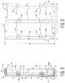
- FIG. 1is a perspective view of an exterior face of a wall assembly having a frame assembly, a sheathing layer, a spacer, and an exterior covering;
- FIG. 2is a front view of the frame assembly showing a top member, a bottom member, and vertical members;
- FIG. 3is a cross-sectional view of the wall assembly taken along line 3 - 3 of FIG. 1 ;
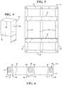
- FIG. 4is an enlarged perspective view of the spacer
- FIG. 5is a front view of the frame assembly showing the spacer extending a length of the frame assembly
- FIG. 6is a cross-sectional view of the wall assembly taken along line 6 - 6 of FIG. 1 ;
- FIG. 7is a front view of the frame assembly
- FIG. 8is a cross-sectional view of the wall assembly showing the spacer
- FIG. 9is a cross-sectional view of the wall assembly showing an inner foam layer coupled to an insulating layer
- FIG. 10is a cross-sectional view of the wall assembly showing the insulating layer extending into voids defined between the vertical members;
- FIG. 11is a cross-sectional view of the wall assembly showing the insulating layer extending into voids defined between the vertical members.
- the wall assembly 20is for constructing a building, such as a residential building or a commercial building.
- the wall assembly 20is at least one of a plurality of exterior walls of the building. It is to be appreciated that the wall assembly 20 may only be one of the plurality of exterior walls of the building or the wall assembly 20 may be all of the plurality of exterior walls of the building. Said differently, the wall assembly 20 may be used to construct a single exterior wall of the building.
- multiple wall assemblies 20may be used to construct the exterior walls of building. Said differently, the wall assembly 20 may be coupled to another wall assembly 20 to define a perimeter of the building. Additionally, the wall assembly 20 may be coupled to a traditional field constructed wall to define the perimeter of the building. It is to be appreciated that the wall assembly 20 may be coupled to the traditional field constructed wall or the another wall assembly 20 by any suitable methods. For example, fasteners 44 , such as nails or screws, an adhesive bead, bolts, cam locks, or straps could be used to the couple together the adjacent wall assemblies 20 .
- fasteners 44such as nails or screws, an adhesive bead, bolts, cam locks, or straps could be used to the couple together the adjacent wall assemblies 20 .
- the wall assembly 20can be manufactured in any length L or height H desired for use as the exterior walls of the building. Additionally, the wall assembly 20 may be used completely above grade or extend below grade such that a portion of the wall assembly 20 is embedded within the ground. Furthermore, the wall assembly 20 can be used as interior walls of the building.
- the wall assembly 20may be manufactured by assembling the wall assembly 20 off-site from the location of the building. Said differently, the wall assembly 20 may be manufactured at a location that is different from the location that the building is to be constructed. For example, the wall assembly 20 can be manufactured at a factory or a warehouse and subsequently transported to the location that the building is to be constructed. Once the wall assembly 20 is delivered on-site, the wall assembly 20 is secured in position on a support structure of the building, such as a footer or stem wall, foundation wall, first, second, or third floor walls, and/or another wall assembly 20 .
- a support structure of the buildingsuch as a footer or stem wall, foundation wall, first, second, or third floor walls, and/or another wall assembly 20 .
- the wall assembly 20may be manufactured on-site at the location where the building is to be constructed. It is to be appreciated that the wall assembly 20 may be positioned with the assistance of machinery, such as a crane. Typically, once the wall assembly 20 is secured in position, the wall assembly 20 receives an exterior covering 22 of the building.
- the exterior covering 22may be a typical cladding such as siding, brick, stucco, cultured stone, fiber cement, wood, insulating foam panel, vinyl, and combinations thereof.
- the wall assembly 20may receive the exterior covering 22 prior to arriving on-site, i.e., in the factor or the warehouse.
- the exterior covering 22may be secured to the wall assembly 20 by exterior fasteners 44 , such as nails, screws, or ties.
- the wall assembly 20may include brick ties as the exterior fasteners 44 .
- the exterior covering 22may be secured to the wall assembly 20 by an adhesive.
- panels of the sidingmay be adhesively bonded to the wall assembly 20 .
- the exterior covering 22is the outermost layer of the wall assembly 20 , once the wall is completed. For example, when the wall assembly 20 is assembled without the exterior covering 22 , it is understood that the wall assembly 20 is not complete. Once the exterior covering 22 is added to the wall assembly 20 , the wall assembly 20 is deemed complete.
- the wall assembly 20includes a frame assembly 24 .
- the frame assembly 24includes a top member 26 and a bottom member 28 spaced from the top member 26 .
- the top and bottom members 26 , 28extend horizontally when the wall assembly 20 is installed.
- the top member 26has a top interior surface 30 configured to face an interior of the structure and a top exterior surface 32 configured to face the exterior of the structure. Said differently, the top interior surface 30 of the top member 26 is configured to face the inside of the building or structure. The top exterior surface 32 of the top member 26 is configured face the outside of the building or structure. A top member depth TMD of the top member 26 is defined between the top interior surface 30 and the top exterior surface 32 of the top member 26 .
- the bottom member 28is spaced from the top member 26 .
- the top and bottom members 26 , 28are substantially parallel with each other.
- the bottom member 28has a bottom interior surface 34 configured to face the interior of the structure and a bottom exterior surface 36 configured to face the exterior of the structure.
- a bottom member depth BMD of the bottom member 28is defined between the bottom interior surface 34 and the bottom exterior surface 36 of the bottom member 28 .
- the frame assembly 24also includes a plurality of vertical members 38 spaced from each other and coupled to and extending between the top and bottom members 26 , 28 .
- Each of the plurality of vertical members 38has a vertical member depth VMD that is less than the top member depth TMD and the bottom member depth BMD. More specifically, each of the vertical members 38 has a vertical interior surface 40 configured to face an interior of the structure and a vertical exterior surface 42 configured to face the exterior of the structure.
- the vertical member depth VMDis defined between the vertical interior surface 40 and the vertical exterior surface 42 of the vertical members 38 .
- the plurality of vertical members 38are spaced from the top exterior surface 32 of the top member 26 and spaced from the bottom exterior surface 36 of the bottom member 28 . Said differently, the vertical members 38 are recessed relative to the top exterior surface 32 of the top member 26 and the bottom exterior surface 36 of the bottom member 28 . More specifically, the vertical exterior surface 42 of the vertical members 38 are spaced from the top exterior surface 32 of the top member 26 and spaced from the bottom exterior surface 36 of the bottom member 28 .
- the top exterior surface 32 of the top member 26 , the bottom exterior surface 36 of the bottom member 28 , and the vertical exterior surface 42 of the vertical members 38present an exterior face of the frame assembly 24 .
- the top interior surface 30 of the top member 26 , the bottom interior surface 34 of the bottom member 28 , and the vertical interior surface 40 of the vertical members 38collectively present an interior face of the frame assembly 24 .
- the interior face of the frame assembly 24faces the interior of the building and the exterior face of the frame assembly 24 faces the exterior of the building.
- the bottom member 28is secured in position on the support structure of the building.
- the frame assembly 24may also include a structural support member for providing resistance to axial loads, shear loads, and lateral loads applied to the wall assembly 20 .
- the frame assembly 24may include wind bracing, hurricane straps, and/or up-lifting clips.
- top and bottom members 26 , 28are horizontal and the vertical members 38 are perpendicular to the top and bottom members 26 , 28 .
- the top and bottom members 26 , 28may be vertical with the vertical members 38 extending horizontally between the top and bottom members 26 , 28 .
- top, bottom, and vertical members 26 , 28 , 38are typically coupled together using fasteners 44 , such as nails and/or screws.
- fasteners 44such as nails and/or screws.
- the top, bottom, and/or the vertical members 38may be couple together in any suitable manner, such as by an adhesive, with or without fasteners 44 .
- the top, bottom, and vertical members 26 , 28 , 38are dimensional lumber.
- the top, bottom, and vertical members 26 , 28 , 38may be any suitable material, such as fiberglass, aluminum, light steel, or other metals.
- the top, bottom, and vertical members 26 , 28 , 38may be different materials relative to each other.
- the top and bottom members 26 , 28may be dimensional lumber while the vertical members 38 may be metal.
- the top, bottom, and vertical members 26 , 28 , 38may be of any desired dimensions.
- the top, bottom, and vertical members 26 , 28 , 38may have a nominal cross-section of 2 inches by 4 inches or a nominal cross-section of 2 inches by 6 inches.
- the top, bottom, and vertical members 26 , 28 , 38may be of different dimensions relative to each other.
- the top and bottom members 26 , 28may have the nominal cross-section of 2 inches by 6 inches and the vertical members 38 may have the nominal cross-section of 2 inches by 4 inches.
- the vertical members 38 along with the top and bottom members 26 , 28define the height H of the wall assembly 20 .
- the height H of the wall assembly 20is of from about 2 to about 24 feet, more typically of from about 6 to about 12 feet, and even more typically of from about 8 to about 12 feet.
- the frame assembly 24has a first end 46 and a second end 48 spaced from the first end 46 .
- one of the vertical members 38is disposed at the first end 46 of the frame assembly 24 and another one of the vertical members 38 is disposed at the second end 48 of the frame assembly 24 with other vertical members 38 spaced between the first and second ends 46 , 48 of the frame assembly 24 .
- the length L of the wall assembly 20is defined between the first and second ends 46 , 48 of the frame assembly 24 .
- a length of the top and bottom members 26 , 28is generally equal to the length L of the wall assembly 20 .
- the length L of the wall assembly 20is of from about 1 to about 52 feet, more typically of from about 5 to about 25 feet, and even more typically of from about 12 to about 16 feet, and even more typical still of from about 8 to about 12 feet.
- the length L of the wall assembly 20may vary depending on specific needs of a customer.
- the length L of the wall assembly 20may be equal to a length of the exterior wall of the building in which the wall assembly 20 is to be used.
- the length L of the wall assembly 20may be shorter than the exterior wall of the building in which the wall assembly 20 is to be used such that multiple wall assemblies 20 are joined together to form a unitary wall of the building.
- the vertical members 38are typically spaced apart from each other a distance DS.
- a plurality of voidsare defined by the vertical members 38 . Said differently, the plurality of voids are between the vertical members 38 .
- the distance DSis measured from a centerline of one of the vertical members 38 to a centerline of another one of the vertical members 38 .
- the vertical members 38are typically equally spaced apart throughout the frame assembly 24 . However, it is to be appreciated that the distance DS between adjacent vertical members 38 may vary throughout the frame assembly 24 . For example, the distance DS between the vertical members 38 may vary for defining an opening in the frame assembly 24 to receive a window frame.
- the distance DS between the vertical members 38may vary for defining other openings in the frame assembly 24 to receive other desired structures, such as door frames.
- the distance DS between adjacent vertical members 38is typically of from about 1 to about 32 inches on-center, more typically of from about 10 to about 32 inches on-center, even more typically of from about 12 to about 28 inches on-center.
- the distance DS between adjacent vertical members 38may be 12, 16, and/or 24 inches on-center.
- the wall assembly 20includes a sheathing layer 50 coupled to the top exterior surface 32 of the top member 26 and coupled to the bottom exterior surface 36 of the bottom member 28 .
- the sheathing layer 50is spaced from the plurality of vertical members 38 thereby defining a gap 52 between the plurality of vertical members 38 and the sheathing layer 50 . More specifically, because the vertical members 38 are recessed from the top exterior surface 32 of the top member 26 and the bottom exterior surface 36 of the bottom member 28 , the sheathing layer 50 is spaced from the vertical members 38 .
- the depth of the gap 52is approximately equal to the difference between the top member depth TMD of the top member 26 and the vertical member depth VMD of the vertical members 38 .
- the sheathing layer 50can be any suitable material.
- the sheathing layer 50may be selected from the group of rigid insulation (polystyrene, polyurethane, polyiso) Oriented strand board (OSB), plywood, fiber board, cementitious board, mineral based boards, such as gypsum and magnesium oxide boards, and combinations thereof.
- OSBrigid insulation
- the fiber boardmay be natural or artificial fibers.
- the sheathing layer 50may be a rigid insulation layer laminated to a structural sheathing, such as OSB, plywood, or a composite material.
- the exterior covering 22may be coupled to the sheathing layer 50 opposite the frame assembly 24 . Said differently, the sheathing layer 50 is configured to receive the exterior covering 22 . It is to be appreciated that the exterior coving may be applied on-site or off-site. Examples of suitable exterior coverings 22 include siding, brick, and/or an insulating foam panels.
- the exterior covering 22may be secured to the wall assembly 20 by exterior fasteners 44 , such as nails, screws, or ties.
- the wall assembly 20may include brick ties as the exterior fasteners 44 .
- the exterior covering 22may be secured to the wall assembly 20 by an adhesive.
- panels of the sidingmay be adhesively bonded to the wall assembly 20 .
- the wall assembly 20also includes at least one spacer 54 coupled to at least one of the plurality of vertical members 38 between the top and bottom members 26 , 28 .
- the spacer 54may be a material selected from the group of wood, metal, plastic, and combinations thereof.
- the spacer 54includes an inner face 56 coupled to at least one of the plurality of vertical members 38 and an outer face 58 coupled to the sheathing layer 50 with an outer periphery 60 of the spacer 54 extending between the inner and outer faces 56 , 58 .
- the spacer 54has a spacer depth SW defined between the inner and outer faces 56 , 58 with the spacer depth SW approximately equal to a difference between the top member depth TMD and the vertical member depth VMD. Said differently, the spacer depth SW is approximately equal to the depth of the gap 52 between the sheathing layer 50 and the vertical members 38 . Said yet another way, the spacer 54 occupies the gap 52 directly between the sheathing layer 50 and the vertical members 38 .
- the sheathing layer 50may be coupled to the spacer 54 for further coupling the sheathing layer 50 to the frame assembly 24 .
- the sheathing layer 50may be coupled to the spacer 54 by exterior fasteners 44 , such as nails, screws, or ties. Additionally, the sheathing layer 50 could be coupled to the spacer 54 by other suitable methods, such as adhesive bonding.
- the wall assembly 20further includes an insulating layer 62 disposed within the gap 52 between the sheathing layer 50 and the plurality of vertical members 38 .
- the insulating layer 62is generally planar. Said differently, the insulating layer 62 is generally parallel to the frame assembly 24 .
- the insulating layer 62may be a preformed panel or may be applied and cured on the sheathing layer 50 , the vertical members 38 , and/or the spacer 54 .
- the insulating layer 62is typically selected from the group of polyurethane foams, polyurea foams, and combinations thereof.
- the insulating layer 62may be any suitable material.
- the insulating layer 62may be a pour in place foam.
- the insulating layer 62may be a sprayable foam selected from the group of polyurethane sprayable foams, polyurea sprayable foams, and combinations thereof.
- the sprayable foammay be selected from the group of acrylic foams, latex foams, melamine foams, isocyanurate foams, and silicone foams.
- the sprayable foammay be the reaction product of a polyether polyol and an isocyanate. It is to be appreciated that any polyether polyols may be used.
- the sprayable foamwhen the sprayable foam is the polyurethane sprayable foam, the sprayable foam may be the reaction product of a polyester polyol and the isocyanate. The use of the polyester polyol imparts the insulating layer 62 with a fire retardant.
- the sprayable foamis a polyurea sprayable foam
- the sprayable foamis the reaction product of a polyamine and an isocyanate.
- An example of an isocyanate suitable for the sprayable foamis lubrinate.
- the insulating layer 62is a plurality of particles and a binder.
- the particles and the binderimpart the insulating layer 62 with strength. More specifically, the insulating layer 62 has a flexural strength typically greater than 25 psi according to ASTM C 203. Additionally, the insulating layer 62 has a compressive resistance of 10%/o deformation at greater than 13 psi according to ASTM D 1621.
- the binderincludes an acrylic-based polymer or copolymer, a styrene-acrylic-based copolymer, a styrene-butadiene-based copolymer, a vinyl acrylic-based copolymer, a vinyl acetate based polymer or copolymer (e.g. ethylene vinyl acetate), and combinations thereof.
- Additional monomers or co-monomers that can be usedinclude linear 1-olefins, branched-chain 1-olefins or cyclic olefins (e.g., ethene, propene, butene, isobutene, pentene, cyclopentene, hexene, and cyclohexene); vinyl and allyl alkyl ethers having 1 to 40 carbon atoms in the alkyl radical, wherein the alkyl radical can possibly carry further substituents such as a hydroxyl group, an amino or dialkylamino group, or one or more alkoxylated groups (e.g., methyl vinyl ether, ethyl vinyl ether, propyl vinyl ether, isobutyl vinyl ether, 2-ethylhexyl vinyl ether, vinyl cyclohexyl ether, vinyl 4-hydroxybutyl ether, decyl vinyl ether, dodecyl vinyl ether, oct
- the monomers usedmay include cross-linking monomers, such as divinylbenzene; 1,4-butanediol diacrylate; methacrylic acid anhydride; monomers containing 1,3-diketo groups (e.g., acetoacetoxyethyl(meth)acrylate or diacetonacrylamide); monomers containing urea groups (e.g., ureidoethyl (meth)acrylate, acrylamidoglycolic acid, and methacrylamidoglycolate methyl ether); and silane cross-linkers (e.g., 3-methacryloxypropyl trimethoxysilane and 3-mercaptopropyl trimethoxysilane).
- cross-linking monomerssuch as divinylbenzene; 1,4-butanediol diacrylate; methacrylic acid anhydride; monomers containing 1,3-diketo groups (e.g., acetoacetoxyethyl(meth)
- cross-linkersinclude N-alkylolamides of ⁇ , ⁇ -monoethylenically unsaturated carboxylic acids having 3 to 10 carbon atoms and esters thereof with alcohols having 1 to 4 carbon atoms (e.g., N-methylolacrylamide and N-methylolmethacrylamide); glyoxal based cross-linkers; monomers containing two vinyl radicals; monomers containing two vinylidene radicals; and monomers containing two alkenyl radicals.
- Exemplary cross-linking monomersinclude diesters or triesters of dihydric and trihydric alcohols with ⁇ , ⁇ -monoethylenically unsaturated monocarboxylic acids (e.g., di(meth)acrylates, tri(meth)acrylates), of which in turn acrylic acid and methacrylic acid can be employed.
- ⁇ , ⁇ -monoethylenically unsaturated monocarboxylic acidse.g., di(meth)acrylates, tri(meth)acrylates
- acrylic acid and methacrylic acidcan be employed.
- alkylene glycol diacrylates and dimethacrylatessuch as ethylene glycol diacrylate, 1,3-butylene glycol diacrylate, 1,4-butylene glycol diacrylate and propylene glycol diacrylate, vinyl methacrylate, vinyl acrylate, allyl methacrylate, allyl acrylate, diallyl maleate, diallyl fumarate and methylenebisacrylamide.
- Functional groups present in the cross-linking monomers included in the binder described hereincan be cross-linked by a chemical reagent.
- the chemical reagentis capable of cross-linking the functional groups of the cross-linking monomers to form, for example, covalent bonds, ionic bonds, hydrogen bonds, metallic bonds, dipole-dipole interactions, and cation-pi interactions.
- Chemical reagents useful in the aqueous latex dispersions described hereininclude, for example, divalent and multivalent cations, such as zirconium (e.g., ammonium zirconium carbonate), zinc (e.g., zinc oxide and/or zinc peroxide), calcium, magnesium, aluminum, iron, tin, titanium, antimony, vanadium, and combinations thereof.
- zirconiume.g., ammonium zirconium carbonate
- zince.g., zinc oxide and/or zinc peroxide
- carbodiimidese.g., polycarbodiimides
- polyisocyanatesorganosilanes (e.g., epoxysilanes), urea-formaldehyde resins, melamine-formaldehyde resins, epoxy containing compounds, aziridines, acrylamides (e.g., N-methyloylacrylamide), hydrazides (e.g., adipic acid dihydrazide), glyoxal condensates, oxazolines, polyethylenimines, polyamines, dialdehydes, and combinations thereof.
- carbodiimidese.g., polycarbodiimides
- organosilanese.g., epoxysilanes
- urea-formaldehyde resinsurea-formaldehyde resins
- melamine-formaldehyde resinsepoxy containing compounds
- aziridinesacrylamides (e.g.,
- the copolymer included in the bindercan be prepared by heterophase polymerization techniques, including, for example, free-radical emulsion polymerization, suspension polymerization, and mini-emulsion polymerization.
- the binderis prepared by polymerizing the monomers using free-radical emulsion polymerization.
- the emulsion polymerization temperatureis generally from 10° C. to 95° C. or from 75° C. to 90° C.
- the polymerization mediumcan include water alone or a mixture of water and water-miscible liquids, such as methanol. In some embodiments, water is used alone.
- the emulsion polymerizationcan be carried out either as a batch, semi-batch, or continuous process.
- a semi-batch processis used.
- a portion of the monomerscan be heated to the polymerization temperature and partially polymerized, and the remainder of the polymerization batch can be subsequently fed to the polymerization zone continuously, in steps or with superposition of a concentration gradient.
- Combined systemscan also be used additionally containing a small amount of a metal compound which is soluble in the polymerization medium and whose metallic component can exist in more than one oxidation state, e.g., ascorbic acid/iron(II) sulfate/hydrogen peroxide, where ascorbic acid can be replaced by the sodium metal salt of hydroxymethanesulfinic acid, sodium sulfite, sodium hydrogen sulfite or sodium metal bisulfite and hydrogen peroxide can be replaced by tert-butyl hydroperoxide or alkali metal peroxydisulfates and/or ammonium peroxydisulfates.
- the carbohydrate derived compoundcan also be used as the reducing component.
- the amount of free-radical initiator systems employedcan be from 0.1 to 2%, based on the total amount of the monomers to be polymerized.
- the initiatorsare ammonium and/or alkali metal peroxydisulfates (e.g., sodium persulfate), alone or as a constituent of combined systems.
- the manner in which the free-radical initiator system is added to the polymerization reactor during the free-radical aqueous emulsion polymerizationis not critical. It can either all be introduced into the polymerization reactor at the beginning, or added continuously or stepwise as it is consumed during the free-radical aqueous emulsion polymerization.
- molecular weight regulatorssuch as tert-dodecyl mercaptan
- tert-dodecyl mercaptansmall amounts (e.g., from 0.01 to 2% by weight based on the total monomer weight) of molecular weight regulators, such as tert-dodecyl mercaptan, can optionally be used.
- molecular weight regulatorssuch as tert-dodecyl mercaptan
- the polymer for use in the binderhas a glass transition temperature (T g ), as measured by differential scanning calorimetry, less than or equal to the temperature of the room in which the binder is used (e.g., in an attic, the T g is 65° C. or less).
- T gglass transition temperature
- the T g of the binder copolymercan be 50° C. or less, 40° C. or less, 30° C. or less, 20° C. or less, or 10° C. or less.
- the polymers for use in the bindercan include self-cross-linking polymers or cross-linkable polymers.
- Specific examples of useful polymers for inclusion in the binder described hereininclude, but are not limited to, ACRONAL NX 4787, acrylic polymers commercially available from BASF Corporation (Florham Park, N.J.).
- the polymers for use in the bindercan also include flame retardant polymers.
- the binder described hereincan include adhesives or sealants.
- suitable adhesivesinclude thermosetting adhesives, thermoplastic adhesives, elastomeric adhesives, and hybrid adhesives.
- the adhesivescan be structural adhesives such as epoxies, epoxy hybrids, formaldehyde based adhesives (e.g., resorcinol formaldehyde, phenol resorcinol formaldehyde, melamine formaldehyde, and urea formaldehyde), phenolics and modified phenolics (nitrile-phenolics, vinyl-phenolics, and neoprene-phenolics), polyaromatic high temperature resins (e.g., polyimides, bismaleimides, and polybenzimidazoles), polyesters, polyurethanes, anaerobic resins, cyanoacrylates, and modified acrylics.
- formaldehyde based adhesivese.g., resorcinol formaldehyde, phenol
- the adhesivescan be non-structural adhesives such as elastomeric resins (e.g., natural rubber, asphalt, reclaimed rubber, butyl rubber, styrene butadiene rubber, polychloroprene, acrylonitrile butadiene, polyisobutylene, polyvinyl methyl ether, polysulfide, and silicone).
- the adhesivescan also be thermoplastic resins, such as polyvinyl acetal, polyvinyl acetate, polyvinyl alcohol, thermoplastic elastomers, ethylene vinyl acetate, cellulosic resins, polyamide, polyester, polyolefins, polysulfone, phenoxy, and acrylic resins.
- the adhesivescan be naturally occurring resins such as natural organic resins (e.g., glues of agricultural or animal origin) or inorganic adhesives and cements (e.g., sodium silicate, phosphate cements, litharge cement, and sulfur cement).
- natural organic resinse.g., glues of agricultural or animal origin
- inorganic adhesives and cementse.g., sodium silicate, phosphate cements, litharge cement, and sulfur cement.
- sealantsexamples include hardening and non-hardening sealants, two-part system sealants, single component sealants, and solvent and water release sealants.
- These sealantscan be low performance sealants (e.g., oil- and resin-based sealants, asphaltic and other bituminous mastics, polyvinyl acetate, epoxy, and polyvinyl chloride plastisol), medium performance sealants (e.g., hydrocarbon rubber-based sealants, acrylic, chlorosulfonated polyethylene, and hot-melt sealants), or high performance sealants (e.g., fluorosilicone and fluoropolymer sealants, polysulfides, polyethers, polyurethanes, silicones, styrene butadiene copolymers, and chloroprenes).
- low performance sealantse.g., oil- and resin-based sealants, asphaltic and other bituminous mastics, polyvinyl acetate, epoxy, and polyvinyl chloride plasti
- the binder described hereincan have a solids percentage of 40% to 85%.
- the bindercan have a solids percentage from 50% to 80%, from 55% to 75%, or from 60% to 70%/o.
- the binderis substantially free of curing agents or cross-linking agents. “Substantially free” means that the binder can include less than 0.1%, less than 0.01%, less than 0.001%, less than 0.0001%, or 0%/o of curing agents or cross-linking agents based on the weight of the binder. In other examples, the binder contains reactive groups that can bond with one or more reactive groups present in the plurality of particles.
- the particles, as described herein,can be pre-expanded polymers that can be fully expanded or partially expanded, for example, with air.
- the pre-expanded polymercan be of from 50 to 99 percent air by volume.
- the pre-expanded polymercan be previously expanded with an organic blowing agent, such as a hydrocarbon like pentane, isopentane, butane and combinations thereof.
- the pre-expanded polymercan be previously expanded with an inorganic blowing agent, such an air, carbon dioxide, nitrogen, argon, and combinations thereof.
- the pre-expanded polymercan be partially expanded, such that the pre-expanded polymer is capable of further expansion, or can be fully expanded.
- the pre-expanded polymeris greater than of about 50 percent expanded, more typically greater than 60 percent expanded, and even more typically greater than 70 percent expanded.
- the particlescan be polymeric particles, non-polymeric particles, and combinations thereof.
- the particlescan be inorganic microspheres and lightweight inorganic particles, such as inorganic particles with a density of from about 10 to 20 kg/m 3 .
- the pre-expanded polymercan be derived from expanded polymers, including thermoplastic polymers.
- pre-expanded polymersinclude polystyrene (e.g. free-radical-polymerized glass-clear polystyrene (GPPS) or anionically polymerized polystyrene (APS)), styrene-based-copolymers (e.g., styrene-maleic anhydride copolymers, styrene-butadiene copolymers, styrene- ⁇ -methylstyrene copolymers, acrylonitrile-butadiene-styrene (ABS) copolymers, styrene-acrylonitrile (SAN) copolymers, styrene-methyl methacrylate copolymers, acrylonitrile-styrene-acrylate (ASA) copolymers, methacrylate-butadiene-sty
- suitable pre-expanded polymersinclude polyphenylene oxide, polystyrene-polyphenylene oxide blends, polyoxymethylene, poly(methyl methacrylate), methyl methacrylate copolymers, ethylene-propylene copolymers (e.g., random and block), ethylene-vinyl acetate copolymers, polycarbonate, polyethylene terephthalate, aromatic polyester/polyether glycol block copolymer, polyethylene and polymerized vinyl aromatic resins.
- vinyl aromatic resinsinclude the solid homopolymers of styrene, vinyltoluene, vinylxylene, ethylvinylbenzene, isopropylstyrene, t-butylstyrene, chlorostyrene, dichlorostyrene, fluorostyrene, bromostyrene; the solid copolymers of two or more monovinyl aromatic compounds; and the solid copolymers of one or more of monovinyl aromatic compounds and a copolymerizable olefinic compound (e.g., acrylonitrile, methyl methacrylate, or ethyl acrylate).
- a copolymerizable olefinic compounde.g., acrylonitrile, methyl methacrylate, or ethyl acrylate.
- the plurality of particlesincludes inorganic particles.
- the inorganic particlescan be hollow, solid, macroporous, inert, and/or non-toxic.
- examples of inorganic particlesinclude, but are not limited to, expanded perlite, hollow glass particles, for example those sold under the trademark NOBLITE® (Noble International, France) or amorphous sililca, for example sold under the trademark such as Nanogel from Aspen Cabot®.
- each of the plurality of particlesis not limited in shape.
- each of the plurality of particlescan be beads, flakes, fibers, rods, disks, cubes, cylinders, pyramids, cones, cuboids, spheres, granules, platelets, microballoons, and combinations thereof.
- the plurality of particlesare uniform in shape (e.g., beads only).
- the plurality of particlesincludes a mixture of two or more shapes (e.g., beads, spheres, and flakes).
- the plurality of particlesare small in size and of low density and overall weight.
- the average particle size of the largest dimension of the plurality of particlesis from 0.1 to 10 mm.
- the plurality of particlesmay include multiple particle sizes.
- the plurality of particlescan include small (i.e., the largest dimension of the pre-expanded polymer is less than 1.0 mm), medium (i.e., the largest dimension of the pre-expanded polymer is from 1.0 to 2.0 mm), and large (i.e., the largest dimension of the pre-expanded polymer is greater than 2.0 mm, such as, for example, from 2.0 mm to 10 mm) particle sizes to provide a closely packed yet breathable barrier, which still defines the pathways 50 .
- the plurality of particlescan be flame retardant. Additionally, flame retardant materials can be added to the binder. Generally, the flame retardant properties of the particles and the binder provide the insulating layer 62 with a flame resistance that meets ASTM E-84.
- suitable flame retardant materials for the binderinclude non-halogenated flame retardant to provide the desired level of flame resistance required.
- Flame retardant particlescan include pre-expanded polymers STYROPOR BF and NEOPOR, expandable polystyrenes commercially available from BASF Corporation (Florham Park, N.J.), and inorganic particles.
- phosphorus flame retardantscan be added to the binder and be either inorganic or organic based. This includes organic phosphate esters, phosphates and inorganic phosphorous containing salts. Phosphate moiety can also be incorporated into the binder.
- metal hydroxidescan be added to the binder formulation to enhance flame resistance, including aluminum trihydrate and magnesium hydroxide. Borates can be used alone or in combination with aluminum trihydrate and magnesium hydroxide. Suitable borates include sodium borate, boric acid and zinc borate. Polydimethylsiloxane alone or in combination with the above mention retardants can also be used. Conventional fillers can be supplemented with silica and talc to further enhance the flame resistance of the insulation drainage board.
- the plurality of particlescan include insulating materials (e.g. fiberglass, rockwool, expanded polystyrene, polyiscyanurate and polyurethane).
- the plurality of particlescan further include recycled material.
- the recycled materialscan be insulating materials.
- the plurality of particlescan include recycled materials such as polymeric organic materials (e.g. polystyrene, polyurethane and polyisocyanurate), inorganic materials (e.g. carbonates, clay, mica, stone, glass, and metal oxides), and combinations thereof.
- Organic polymersinclude, for example, filled and unfilled thermoset/thermoplastic polymers.
- filled polymers materialsare reinforced reaction injection molded (RRIM) thermoset plastic materials that have an organic component including substantially polyurethanes; unreacted precursors of the RRIM polymer such as polyols and isocyanates; sheet molding compounds (SMC) which have an organic component comprising styrene cross-linked polyesters; uncured SMC reactants comprising styrene and unsaturated polyesters; and epoxies, phenolics, silicates, melamines, diallylphthalates, and polyimides as are typically used in reinforced plastics.
- RRIMreinforced reaction injection molded
- SMCsheet molding compounds
- Examples of useful unfilled polymer materialsare reaction injection molded (RIM) plastics, such as unreinforced RIM polyurethanes and polyureas, polyethylenes, polyethylene terephthalate, polystyrenes, and scrap rubber tires that are filled or unfilled polymer materials.
- the recycled polymer materials, inorganic recycled materials, and composite recycled productstypically are ground, shredded, or otherwise comminuted before inclusion in the plurality of particles and can include lightweight or foamed polymer materials such as, but not limited to, ground expanded polystyrene, polyurethane, and other lightweight materials.
- the plurality of particlescan be greater than 80% by volume of the composition.
- the plurality of particlescan be greater than 60%, greater than 70%, greater than 80%, greater than 90%, or greater than 95% by volume of the composition.
- the insulating layer 62may include a filler, such as heat reflective material, fire retardants, and impact modifiers.
- Fillers suitable for use in the compositions described hereininclude ground/recycled glass (e.g., window or bottle glass), milled glass, glass spheres, glass flakes, glass fibers, clays (e.g., kaolin), feldspar, mica, talc, activated carbon, metals and alloys (e.g., nickel, copper, aluminum, silicon, solder, silver, and gold), metal-plated particulates (e.g., silver-plated copper, silver-plated nickel, and silver-plated glass microspheres), sol-gel ceramics (e.g., sol-gel SiO 2 , TiO 2 or Al 2 O 3 ), precipitated ceramics (such as SiO 2 , TiO 2 or Al 2 O 3 ), ceramic microspheres, fused silica, fumed silica, amorphous fused silica, aluminum trihydrate (ATH), sand, ground
- the fillercan include calcium carbonate and/or aluminum trihydrate.
- the fillercan include heat and/or infrared reflective materials, such as those present in RADIANCE e-0.25 AB-C, an acrylic copolymer emulsion/pigment blend commercially available from BASF Corporation (Florham Park, N.J.), and other pigments or metallic flake materials (e.g., aluminum flake materials).
- the compositioncan include a liquid flame retardant, for example, in an amount of 0 to 30% by weight of the composition.
- the compositioncan also include additives such as antioxidants, thickeners, fungicides, biocides, surfactants, defoamers, coalescing agents, tackifiers, plasticizers, dispersants, rheology modifiers, dyes, freeze-thaw agents, wetting agents, other formulating agents, and combinations thereof.
- suitable heat reflective materialinclude, but are not limited to, graphite, and pigments.
- the particles and the binderare mixed to form the insulating layer 62 .
- the bindercoats the particles and is cured to form the insulating layer 62 .
- the insulating layer 62once the binder is cured, can provide insulating properties.
- the particles and bindermay be formed and cured to form preformed panels with the preformed panels subsequently applied to the frame assembly 24 .
- the particles and the bindermay be applied to an sheathing layer 50 , which is coupled to the frame assembly 24 .
- the binderis cured to form the insulating layer 62 , with the insulating layer 62 providing a continuous, bonded, insulation, drainage layer.
- the insulating layer 62is between the sheathing layer 50 and the frame assembly 24 .
- the sheathing layer 50may be a foam layer of a foam selected from the group of polyurethane foams, polyurea foams, and combinations thereof.
- the particles and the binderare applied to and cured on the foam layer to bond the insulating layer 62 to the foam layer.
- the foam layermay be any suitable material, such as plywood and OSB board.
- the preformed panelsmay be coupled directly to the frame assembly 24 by the fasteners 44 .
- the preformed panelsmay be adhesively bonded to the frame assembly 24 .
- the particles and the binderare mixed to form a fluid composition prior to coupling the insulating layer 62 to the frame assembly 24 .
- the fluid compositionmay be rolled or brushed onto the frame assembly 24 .
- the particles and the binderare mixed to form a sprayable composition.
- the sprayable compositionmay be sprayed onto an exterior side 58 of the sheathing layer 50 .
- the particles and the bindermay be mixed to form the sprayable composition prior to applying the sprayable composition to the sheathing layer 50 .
- the sprayable compositionmay be formed and subsequently sprayed onto the exterior side 58 of the sheathing layer 50 to apply the sprayable composition on the sheathing layer 50 .
- the insulating layer 62is seamless across the length L of said frame assembly 24 . Additionally, when the fluid composition or the sprayable composition are used, the insulating layer 62 has a density of from about 0.5 to about 5.00 pounds per cubic foot. Furthermore, when the fluid composition or the sprayable composition are used, the insulating layer 62 typically has an R-value of from about 1.00 to about 9.00 per inch, and more typically of from about 3.00 to about 6.00 per inch.
- Suitable preformed panels for use as the insulating layer 62include products sold under the trade name NEOPOR.
- suitable spray foams for use as the insulating layer 62include products sold under the trade name WALLTITE HP.
- the insulating layer 62has a thickness and provides the wall assembly 20 with a thermal resistance, or R-value.
- the thickness of the insulating layer 62may be approximately equaled to the difference between the top member depth TMD and the vertical member depth VMD.
- the insulating layer 62has a thickness of from about 0.25 to about 3.50 inches, more typically of from about 0.25 to about 2.00 inches, and even more typically or from about 0.50 to about 1.50 inches.
- insulating layer 62has a density of from about 1.00 to about 5.00 pounds per cubic foot, more typically of from about 1.00 to about 4.50 pounds per cubic foot, and even more typically of from about 1.00 to about 2.00 pounds per cubic foot.
- the insulating layer 62typically has an R-value of from about 1.00 to about 9.00 per inch, and more typically, 3.00 to about 7.00 per inch. As described above, the insulating layer 62 is within the gap 52 . Because the insulating layer 62 is disposed within the gap 52 , the insulating layer 62 acts as a thermal break between the sheathing layer 50 and the frame assembly 24 within the wall assembly 20 . Additionally, the spacer 54 may also provide a thermal break between the sheathing layer 50 and the frame assembly 24 .
- the insulating layer 62encapsulates the outer periphery 60 of the spacer 54 .
- the insulating layer 62surrounds the outer periphery 60 of the spacer 54 .
- the insulating layer 62directly abuts the spacer 54 on all surfaces of the spacer 54 not covered by the sheathing layer 50 or the vertical members 38 . Because the insulating layer 62 encapsulates the outer periphery 60 of the spacer 54 , the insulating layer 62 contributes to the shear strength of the wall assembly 20 as the insulating layer 62 acts against the outer periphery 60 of the spacer 54 as the wall assembly 20 experiences shear stresses.
- the spacer 54acts as a wedge to prevent the insulating layer 62 from moving relative to the frame assembly 24 due to stresses acting on the wall assembly 20 . Additionally, the inclusion of the insulating layer 62 between the vertical members 38 further enhances to the structural integrity of the wall assembly 20 .
- the wall assembly 20may include more than one spacer 54 .
- the spacer 54may be further defined as a first spacer 54 A and the wall assembly 20 may further include a second spacer 54 B.
- the second spacer 54 Bcan be coupled to another one of the plurality of vertical members 38 relative to the first spacer 54 A.
- the second spacercan be on the same vertical member relative to the first spacer 54 A.
- the second spacer 54 Bis spaced from said first spacer 54 A.
- the spacer 54may be coupled to more than one of the vertical members 38 , as shown in FIG. 5 .
- the spacer 54may be coupled to at least two of the plurality of vertical members 38 .
- the spacer 54may extend for the length L of the wall.
- the spacers 54may be coupled to multiple vertical members 38 without extending the length L of the wall assembly 20 , as shown in FIG. 2 .
- the spacer 54has a rectangular cross-section. However, as shown in FIGS. 6 and 8 , the spacer 54 may have other cross-sections, such as U-shaped, L-shaped, Z-shaped. More specifically, the inner face 56 of the spacer 54 has a base segment 64 . The inner face 56 of the spacer 54 may also have a leg segment 66 extending from the base segment 64 with the base segment 64 and the leg segment 66 presenting the spacer 54 with the L-shaped cross-section and cooperatively defining an L-shaped cavity. When present, at least one vertical member 38 may be disposed within the L-shaped cavity such that the spacer 54 extends along one side of the vertical member 38 .
- the leg segment 66 of the spacer 54may be further defined as a first leg segment 66 A and the spacer 54 further includes a second leg segment 66 B spaced from the first leg segment 66 A and extending from the base segment 64 .
- the base segment 64 and the first and second leg segments 66 A, 66 Bpresent the spacer 54 with the U-shaped cross-section and cooperatively defining a U-shaped cavity.
- at least one vertical member 38may be disposed within the U-shaped cavity such that the spacer 54 wraps around at least a portion of the vertical member 38 .
- one example of the spacer 54may include a connecting member 68 connecting the inner face 56 and the outer face 58 of the spacer 54 .
- the spacer 54may the connecting member 68 with the connecting member 68 interconnecting the inner face 56 and the outer face 58 of the spacer 54 to present the spacer 54 with the Z-shaped configuration.
- the spacer 54may have any suitable configuration or shape needed in order to create the desired space.
- the wall assembly 20may include any number of spacers 54 .
- the wall assembly 20may include 6 spacers 54 as shown in FIG. 7 .
- multiple spacers 54may be disposed on the same vertical member 38 .
- the spacers 54 usedmay have different cross-sectional areas.
- spacers 54 used on one vertical member 38may have the U-shaped cross-section and the spacers 54 used on another vertical member 38 may have the L-shaped cross-section, as shown in FIG. 6 .
- a strength of the wall assembly 20can be modified. For example, having a U-shaped spacer 54 increases the surface area of the spacer 54 that the insulating layer 62 contacts, thereby increasing the shear strength of the wall assembly 20 .
- the wall assembly 20may include an inner foam layer 70 applied to the insulating layer 62 and extending into the frame assembly 24 . More specifically, when present the inner foam layer 70 is disposed between the vertical members 38 . It is to be appreciated that the inner foam layer 70 may be in contact with the vertical members 38 or, alternatively, the inner foam layer 70 may be spaced from the vertical members 38 while still being disposed between the vertical members 38 . The inner foam layer 70 can be used to increase the R-value of the wall assembly 20 . Alternatively, the insulating layer 62 may extend in between the vertical members 38 of the frame assembly 24 thereby making the inner foam layer 70 unnecessary, as shown in FIGS. 10 and 11 .
- the inner foam layer 70is typically selected from the group of polyurethane foams, polyurea foams, and combinations thereof.
- the inner foam layer 70may be any suitable material.
- the inner foam layer 70may be a sprayable foam selected from the group of polyurethane sprayable foams, polyurea sprayable foams, and combinations thereof.
- the sprayable foammay be selected from the group of acrylic foams, latex foams, melamine foams, isocyanurate foams, and silicone foams.
- the sprayable foamis a polyurethane sprayable foam
- the sprayable foammay be the reaction product of a polyether polyol and an isocyanate. It is to be appreciated that any polyether polyols may be used.
- the sprayable foamwhen the sprayable foam is the polyurethane sprayable foam, the sprayable foam may be the reaction product of a polyester polyol and the isocyanate.
- the use of the polyester polyolimparts the insulating layer 62 with a fire retardant.
- the sprayable foamis a polyurea sprayable foam
- the sprayable foamis the reaction product of a polyamine and an isocyanate.
- An example of an isocyanate suitable for the sprayable foamis lubrinate.
- the insulating layer 62provides structural support to the frame assembly 24 .
- the insulating layer 62 and/or the inner foam layer 70may couple the top, bottom, and vertical members 26 , 28 , 38 together thereby reducing the number of fasteners 44 needed to structurally secure the top, bottom, and vertical members 26 , 28 , 38 together.
- the inner foam layer 70may reduce the amount of fasteners 44 or even eliminate the fasteners 44 needed to couple together the top, bottom, and vertical members 26 , 28 , 38 such that the frame assembly 24 is free of fasteners 44 while still meeting structural requirements.
- the insulating layer 62is typically applied to the frame assembly 24 off-site from the location where the building is to be constructed.
- the wall assembly 20may be manufactured at a location that is different from the location that the building is to be constructed, such as the factory or warehouse. Manufacturing the wall assembly 20 off-site decreases labor cost for constructing the building and decreases construction time required to construct the building once the wall assembly 20 is on-site.
- the wall assembly 20may include a barrier layer coupled to the sheathing layer 50 opposite the insulating layer 62 .
- the barrier layermay be an additional weather resistant barrier, and/or a radiant barrier.
- the barrier layermay be any suitable weather resistant barrier or radiant barrier, including fluid applied weather resistant barriers. Examples of fluid weather resistant barriers include sprayable weather resistant barriers and radiant barriers and roller or brush applied weather resistant barriers and radiant barriers.
- the insulting layer and/or the inner foam layer 70may include a chase portion for receiving utilities, such as electrical wires and/or plumbing. It is to be appreciated that the chase portion may run vertically within the insulating layer 62 and/or the inner foam layer 70 such that the chase portion are parallel to the vertical members 38 or the chase portion may run horizontally within the insulating layer 62 and/or the inner foam layer 70 such that the chase portion are perpendicular to the vertical members 38 .
- the methodincludes the step of providing the frame assembly 24 including the top member 26 and the bottom member 28 with each of the top and bottom members 26 , 28 having the interior surface configured to face the interior of the structure and the exterior surface configured to face the exterior of the structure.
- the frame assembly 24also includes the plurality of vertical members 38 spaced from each other and coupled to and extending between the top and bottom members 26 , 28 with the plurality of vertical members 38 spaced from the exterior surface of the top and bottom members 26 , 28 .
- the methodalso includes the step of coupling the spacer 54 to at least one of the plurality of vertical members 38 of the frame assembly 24 between the top and bottom members 26 , 28 .
- the methodfurther includes the step of coupling the sheathing layer 50 to the top and bottom members 26 , 28 and to the spacer 54 with the sheathing layer 50 spaced from the plurality of vertical members 38 by the spacer 54 .
- the methodfurther includes the step of applying the insulating layer 62 within the gap 52 between the sheathing layer 50 and the plurality of vertical members 38 with the insulating layer 62 encapsulating the outer periphery 60 of the spacer 54 .
- the insulating layer 62is applied to the sheathing layer 50 opposite the frame assembly 24 .
- the step of applying the insulating layer 62is further defined as spraying foam onto the sheathing layer 50 and the vertical members 38 to form the insulating layer 62 .
- the methodwould include the step of curing the insulating layer 62 thereby forming the wall assembly 20 .
- the step of curing the bindermay be passive, i.e., there is no need for an affirmative step, such as heating, etc. to cure the binder. Said differently, the binder may cure naturally via a respective curing mechanism of the binder composition. Alternatively, an affirmative step, such as applying heat to the binder, may be required to cure the binder.
- the step of providing the frame assembly 24may be further defined as assembling the frame assembly 24 with the plurality of vertical members 38 coupled between the top member 26 and the bottom member 28 .
- the methodmay include the step of applying the inner foam layer 70 to the sheathing layer 50 between the vertical members 38 of the frame assembly 24 .
- the insulating layer 62 and/or the sheathing layer 50may be coupled to the frame assembly 24 either on-site where the building is to be constructed or off-site at a factory or warehouse.
- the insulating layer 62may be made from preformed panels with the preformed panels being applied to the frame assembly 24 .
- the methodmay include the step of providing the preformed panels for the insulating layer 62 .
- the insulating layer 62may be sprayed, brushed or rolled onto the sheathing layer 50 .
Landscapes
- Engineering & Computer Science (AREA)
- Architecture (AREA)
- Civil Engineering (AREA)
- Structural Engineering (AREA)
- Life Sciences & Earth Sciences (AREA)
- Wood Science & Technology (AREA)
- Physics & Mathematics (AREA)
- Electromagnetism (AREA)
- Building Environments (AREA)
Abstract
Description
Claims (18)
Priority Applications (1)
| Application Number | Priority Date | Filing Date | Title |
|---|---|---|---|
| US15/543,872US10801197B2 (en) | 2015-01-19 | 2016-01-19 | Wall assembly having a spacer |
Applications Claiming Priority (3)
| Application Number | Priority Date | Filing Date | Title |
|---|---|---|---|
| US201562104955P | 2015-01-19 | 2015-01-19 | |
| PCT/US2016/013880WO2016118490A1 (en) | 2015-01-19 | 2016-01-19 | Wall assembly having a spacer |
| US15/543,872US10801197B2 (en) | 2015-01-19 | 2016-01-19 | Wall assembly having a spacer |
Publications (2)
| Publication Number | Publication Date |
|---|---|
| US20180016781A1 US20180016781A1 (en) | 2018-01-18 |
| US10801197B2true US10801197B2 (en) | 2020-10-13 |
Family
ID=55398411
Family Applications (1)
| Application Number | Title | Priority Date | Filing Date |
|---|---|---|---|
| US15/543,872ActiveUS10801197B2 (en) | 2015-01-19 | 2016-01-19 | Wall assembly having a spacer |
Country Status (3)
| Country | Link |
|---|---|
| US (1) | US10801197B2 (en) |
| CA (1) | CA2973726C (en) |
| WO (1) | WO2016118490A1 (en) |
Cited By (4)
| Publication number | Priority date | Publication date | Assignee | Title |
|---|---|---|---|---|
| US11541625B2 (en)* | 2015-01-19 | 2023-01-03 | Basf Se | Wall assembly |
| US20230049445A1 (en)* | 2021-08-12 | 2023-02-16 | Plank Structural Systems LLC | Foam filled structural plank building foundation with laminated reinforcement |
| US20240117628A1 (en)* | 2022-10-10 | 2024-04-11 | Brian IVERSON | Modular complete thermal break foundation, wall and roof assemblies for buildings |
| US20250075497A1 (en)* | 2023-01-30 | 2025-03-06 | Citra Group Ag | Structure and construction method |
Families Citing this family (9)
| Publication number | Priority date | Publication date | Assignee | Title |
|---|---|---|---|---|
| US9879400B1 (en) | 2016-07-07 | 2018-01-30 | Robert P. Walker | Device and method for foundation drainage |
| CN106522460B (en)* | 2016-11-29 | 2018-11-16 | 马计划 | A heat-insulating and sound-absorbing wall body and preparation method thereof |
| US11007921B2 (en) | 2017-10-03 | 2021-05-18 | Build Ip Llc | Wheeled assembly for item transport |
| JP7629857B2 (en) | 2019-02-14 | 2025-02-14 | ボクサブル インク | Surrounding structure of enclosure components |
| US11718984B2 (en) | 2021-01-12 | 2023-08-08 | Build Ip Llc | Liftable foldable transportable buildings |
| US11739547B2 (en) | 2021-01-12 | 2023-08-29 | Build Ip Llc | Stackable foldable transportable buildings |
| US12104368B2 (en) | 2021-11-22 | 2024-10-01 | Merged Materials | Layered panels |
| US20230160205A1 (en)* | 2021-11-22 | 2023-05-25 | Merged Materials | Layered Panels |
| WO2024040244A2 (en)* | 2022-08-19 | 2024-02-22 | Owens Corning Intellectual Capital, Llc | Multi-material sheathing system with sustained thermal insulation performance |
Citations (297)
| Publication number | Priority date | Publication date | Assignee | Title |
|---|---|---|---|---|
| US1028725A (en) | 1911-01-11 | 1912-06-04 | Ernest Franklin Hodgson | Roof construction. |
| US1549292A (en) | 1923-11-05 | 1925-08-11 | George A Buttress | Composition lath board |
| US1637410A (en) | 1922-12-23 | 1927-08-02 | Truscon Steel Co | Coated metal lath |
| US1914345A (en) | 1932-07-07 | 1933-06-13 | United States Gypsum Co | Wall construction |
| US2015817A (en) | 1925-07-04 | 1935-10-01 | Int Alfol Mij Nv | Heat insulation for wall structures |
| US2116270A (en) | 1932-09-19 | 1938-05-03 | Grand Joseph M Le | Building structure |
| US2318820A (en) | 1938-06-04 | 1943-05-11 | Johns Manville | Building construction |
| US2324971A (en) | 1940-02-03 | 1943-07-20 | Minnesota & Ontario Paper Co | Wall |
| US2514170A (en) | 1945-10-12 | 1950-07-04 | Raybestos Manhattan Inc | Insulating material |
| US2553881A (en) | 1948-01-15 | 1951-05-22 | Suttles Omar | Ventilating system for house trailers |
| US2645824A (en) | 1949-09-13 | 1953-07-21 | Edwin J Titsworth | Ventilated wall |
| US2755728A (en) | 1952-06-12 | 1956-07-24 | Raymond A Frisby | Closure for ventilators |
| US2767961A (en) | 1953-02-26 | 1956-10-23 | William H Frankland | Radiant heating and air conditioning system |
| US2876871A (en) | 1953-07-29 | 1959-03-10 | Robertson Co H H | Wall panel |
| US2999571A (en)* | 1958-09-12 | 1961-09-12 | Peter H Huber | Powder-actuated fastener |
| US3006113A (en) | 1957-02-12 | 1961-10-31 | Foil Process Corp | Self-cooling roof structure |
| US3086323A (en) | 1959-02-27 | 1963-04-23 | Thermovent Products Corp | Ventilated building |
| US3115819A (en) | 1961-03-06 | 1963-12-31 | Sheffield Corp | Prefabricated enclosure |
| US3147336A (en) | 1962-04-17 | 1964-09-01 | Howard G Mathews | Laminate panels for constructing enclosure |
| US3196773A (en) | 1962-08-06 | 1965-07-27 | Reynolds Metals Co | Building system with ventilating means |
| US3251163A (en) | 1962-04-05 | 1966-05-17 | Lockheed Aircraft Corp | Clamp joint construction for prefabricated panels |
| US3258889A (en) | 1962-04-16 | 1966-07-05 | Upson Co | Prefabricated stud panel with foam insulation connector |
| US3295278A (en) | 1963-04-03 | 1967-01-03 | Plastitect Ets | Laminated, load-bearing, heat-insulating structural element |
| US3343474A (en) | 1964-09-22 | 1967-09-26 | Sohda Yoshitoshi | Building with a vent device |
| GB1097452A (en) | 1963-11-21 | 1968-01-03 | Yoshitoshi Sohda | Wall and roof components for buildings or like constructions |
| US3394576A (en)* | 1964-06-15 | 1968-07-30 | United Eng Foundry Co | Rolling mill |
| DE1281133B (en) | 1964-05-09 | 1968-10-24 | Georg Anton Wissler | Flat roof covering made of double-shell elements laid side by side |
| US3474583A (en)* | 1968-09-11 | 1969-10-28 | Robertson Co H H | Insulated metal wall structure |
| US3482367A (en) | 1968-04-12 | 1969-12-09 | Robertson Co H H | Field erected insulated wall structure |
| GB1196469A (en) | 1967-12-08 | 1970-06-24 | N R T Mouldings Ltd | A method of and means for Ducting the Roofs of Buildings |
| US3595728A (en) | 1966-06-20 | 1971-07-27 | Nuclear Power Group Ltd | Thermal insulation |
| US3605365A (en) | 1969-09-08 | 1971-09-20 | Allan J Hastings | Plastic foam building panel |
| US3616139A (en) | 1969-01-21 | 1971-10-26 | Peter Jones | Multilayered thermal insulators |
| US3633659A (en) | 1969-01-20 | 1972-01-11 | Sisenca Sa | Roof constructions |
| US3683785A (en) | 1970-06-11 | 1972-08-15 | Howard L Grange | Roof construction providing air flow from eave to ridge |
| US3736715A (en) | 1971-09-15 | 1973-06-05 | Nomeco Building Specialties In | Prefabricated walls |
| US3748803A (en) | 1970-04-09 | 1973-07-31 | Svenska Flaektfabriken Ab | Arrangement at buildings assembled of pre-fabricated wall and roof element |
| US3756895A (en) | 1968-08-26 | 1973-09-04 | Selby Battersby & Co | Vented roof systems employing microporous membranes |
| US3780638A (en) | 1971-12-03 | 1973-12-25 | E Burghartz | Construction for the ventilation and air conditioning of rooms of existing buildings |
| US3783563A (en) | 1971-07-06 | 1974-01-08 | Moorex Ind Inc | Prefabricated building components |
| US3785913A (en) | 1971-08-12 | 1974-01-15 | Hallamore Homes | Prefabricated construction panel |
| US3789747A (en) | 1972-12-15 | 1974-02-05 | Industrial Acoustics Co | Ventilated acoustic structural panel |
| US3797180A (en) | 1972-07-17 | 1974-03-19 | H Grange | Ventilated roof construction |
| US3816234A (en) | 1971-03-22 | 1974-06-11 | Burden W | Impact absorbing laminate and articles fabricated therefrom |
| US3868796A (en) | 1973-04-04 | 1975-03-04 | Ford Motor Co | Side door intrusion protection |
| US3885008A (en) | 1969-11-26 | 1975-05-20 | Robert E Martin | Method for producing prefabricated wall section with molded panels |
| US3952471A (en) | 1974-08-05 | 1976-04-27 | Mooney Edward L | Precast wall panel and building erected on site therefrom |
| US3972164A (en) | 1974-03-11 | 1976-08-03 | Grange Howard L | Roof construction with inlet and outlet venting means |
| US3982360A (en) | 1974-03-20 | 1976-09-28 | Newman Ernest L | Mobile home roof apparatus |
| US4019297A (en) | 1974-07-29 | 1977-04-26 | David V. Munnis | Construction panel |
| US4028289A (en) | 1976-10-05 | 1977-06-07 | Vast Products Inc. | Foamed polyester resin |
| US4047355A (en) | 1976-05-03 | 1977-09-13 | Studco, Inc. | Shaftwall |
| US4057123A (en) | 1975-12-03 | 1977-11-08 | Conwed Corporation | Lightweight sound absorbent panels having high noise reduction coefficient |
| US4067155A (en) | 1975-08-28 | 1978-01-10 | Grefco, Inc. | Sealing system |
| US4069628A (en) | 1976-05-05 | 1978-01-24 | Pease Company | Eave thermal baffle for insulation |
| US4080881A (en) | 1975-05-22 | 1978-03-28 | Campbell Research Corporation | Building construction |
| US4096790A (en) | 1977-06-24 | 1978-06-27 | Curran Laurence E | Ventilation and insulation baffle |
| US4099355A (en) | 1976-07-07 | 1978-07-11 | Horst Lampertz | Paneling of fireproof insulating elements for walls, floors and ceilings |
| US4102092A (en) | 1977-04-15 | 1978-07-25 | Ward Bruce K | Venting device |
| US4104840A (en) | 1977-01-10 | 1978-08-08 | Inryco, Inc. | Metal building panel |
| US4114338A (en)* | 1977-05-09 | 1978-09-19 | Armco Steel Corporation | Reinforcing plate for overlapped joints |
| US4125971A (en) | 1977-09-19 | 1978-11-21 | Diversified Insulation, Inc. | Vent and baffle |
| EP0004216A1 (en) | 1978-03-07 | 1979-09-19 | ETABLISSEMENTS D'ARDOREL Société Anonyme française | Cladding for thermally insulating and protecting a rigid construction or structure against adverse weather conditions and use of such a cladding for a house |
| FR2421344A1 (en) | 1978-03-30 | 1979-10-26 | Cousquer Lucien | Air conditioning system for animal house - has air ducts in sloping roof, with dampers giving choice of air flow patterns |
| US4185437A (en) | 1978-10-10 | 1980-01-29 | Olympian Stone Company | Building wall panel and method of making same |
| US4201121A (en) | 1978-07-31 | 1980-05-06 | Brandenburg Frank J Jr | Method of venting heat from homes |
| US4214510A (en) | 1978-09-14 | 1980-07-29 | Ward Bruce K | Vent and baffle unit |
| US4223489A (en) | 1978-11-29 | 1980-09-23 | Bentley Billy E | Insulation stop |
| SU775258A1 (en) | 1978-08-07 | 1980-10-30 | За витель 54) ПОКРЫТИЕ у-г S Г I ИЯ . . ;: t-r- :- | Roofing |
| US4237672A (en) | 1979-04-09 | 1980-12-09 | Lloyd Plastics Company | Roofing vent and installation tool |
| US4254598A (en) | 1979-05-21 | 1981-03-10 | Rugroden Roger R | Thermally isolated roof structure |
| US4286420A (en) | 1979-04-18 | 1981-09-01 | Pharmakidis Panayiotis D | Heat retention wall system |
| US4295304A (en) | 1978-04-04 | 1981-10-20 | Star Manufacturing Company Of Oklahoma | Prefabricated panel construction system |
| FR2481341A1 (en) | 1980-04-29 | 1981-10-30 | Haironville Forges D | Composite insulating roofing panel - includes spacers which create cavities between exterior and interior panels permitting air to circulate |
| US4308308A (en) | 1979-02-08 | 1981-12-29 | Chemie Werk Weinsheim Gmbh | Multilayer anti-drumming and stiffening sheeting |
| US4329823A (en)* | 1979-11-13 | 1982-05-18 | Encon Products, Inc. | Support spacer apparatus |
| US4333290A (en) | 1979-05-10 | 1982-06-08 | Arizona Diversified Products, Inc. | Structural member for installation system |
| US4344413A (en) | 1980-04-21 | 1982-08-17 | Gulf States Manufacturers, Inc. | Solar heating panel for metal buildings |
| US4346541A (en) | 1978-08-31 | 1982-08-31 | G & S Company | Building panel construction and panel assemblies utilizing same |
| US4382435A (en) | 1978-02-24 | 1983-05-10 | Cresent Roofing Company Limited | Roofing panels |
| US4429503A (en) | 1979-06-29 | 1984-02-07 | Reynolds Metals Company | Insulated panel |
| US4446661A (en) | 1979-02-19 | 1984-05-08 | Jonsson Jan U E | Spacer means for providing air gaps |
| US4453359A (en) | 1982-05-07 | 1984-06-12 | Olympian Stone Company, Inc. | Building wall panel |
| EP0111235A2 (en) | 1982-12-04 | 1984-06-20 | BASF Aktiengesellschaft | Prefabricated composite element for the external insulation of building-walls |
| US4471591A (en) | 1983-08-08 | 1984-09-18 | Jamison Walter E | Air impervious split wall structure |
| GB2145756A (en) | 1983-08-30 | 1985-04-03 | Marley Extrusions | Roof ventilation |
| US4528789A (en)* | 1979-11-13 | 1985-07-16 | Encon Products, Inc. | Insulated roof system |
| US4593511A (en) | 1983-06-01 | 1986-06-10 | Oy Partek Ab | Panel for exterior insulation |
| FR2576943A1 (en) | 1985-02-01 | 1986-08-08 | Cuisenier Jean Pierre | VESTURE INSULATION PROCESS |
| US4635419A (en) | 1983-05-16 | 1987-01-13 | Forrest Joseph C | Vented roof construction |
| US4637190A (en) | 1983-07-15 | 1987-01-20 | Minialoff Gerrard O | Building panel |
| US4641469A (en) | 1985-07-18 | 1987-02-10 | Wood Edward F | Prefabricated insulating panels |
| US4661533A (en) | 1985-10-28 | 1987-04-28 | The Dow Chemical Company | Rigid polyurethane modified polyisocyanurate containing fly ash as an inorganic filler |
| US4660463A (en) | 1982-11-13 | 1987-04-28 | Glidevale Building And Products, Ltd. | Roof space ventilator |
| US4677903A (en) | 1985-07-26 | 1987-07-07 | Mathews Iii J F | Construction utilizing a passive air system for the heating and cooling of a building structure |
| US4683688A (en) | 1984-03-16 | 1987-08-04 | Wojcinski Allan S | Containerized shooting range |
| US4698366A (en) | 1984-02-09 | 1987-10-06 | Stichting Iwl | Method for the manufacture of insulating porous shaped building articles |
| US4736561A (en) | 1981-12-14 | 1988-04-12 | Loadmaster Systems, Inc. | Roof deck construction |
| GB2196032A (en) | 1986-10-04 | 1988-04-20 | Frederick Panton | Broiler house with closable ventilation holes in roof ridge |
| US4747249A (en)* | 1985-11-01 | 1988-05-31 | Amca International Corporation | Subpurlin and attachment assembly |
| US4754587A (en) | 1986-12-22 | 1988-07-05 | Glaser Donald L | Thermal break panel |
| US4832308A (en) | 1986-01-31 | 1989-05-23 | Ontario Inc. | Panel for concrete formwork |
| US4852314A (en) | 1986-12-11 | 1989-08-01 | Moore Jr Thomas W | Prefabricated insulating and ventilating panel |
| US4858403A (en) | 1988-06-01 | 1989-08-22 | Lingle Cleo M | Fastening bar assembly for frameless insulating panels |
| US4916875A (en) | 1988-07-18 | 1990-04-17 | Abc Trading Co., Ltd. | Tile-mount plate for use in wall assembly |
| US4942711A (en) | 1988-01-19 | 1990-07-24 | Swedal-Systems Hb | Outer walls or roofs |
| US4960184A (en) | 1989-11-09 | 1990-10-02 | Bruce Woodward | Sound absorbing structure |
| US4995308A (en) | 1989-05-24 | 1991-02-26 | Alumax Inc. | Roof ventilating apparatus |
| US5009043A (en) | 1990-07-12 | 1991-04-23 | Herman Miller, Inc. | Acoustic panel |
| CA1284571C (en) | 1987-06-23 | 1991-06-04 | Peter E. Kayne | Rapid assembly building system |
| CA2006652A1 (en) | 1989-12-27 | 1991-06-27 | Balther J. Jensen | Polaris wall building component |
| US5033248A (en) | 1990-01-05 | 1991-07-23 | Phillips Charles N | Reinforced concrete building and method of construction |
| US5102260A (en) | 1991-01-17 | 1992-04-07 | Horvath John S | Geoinclusion method and composite |
| US5172532A (en) | 1988-04-01 | 1992-12-22 | Gibbar Jr James H | Prefabricated polymer building wall panels |
| US5192598A (en) | 1991-09-16 | 1993-03-09 | Manville Corporation | Foamed building board composite and method of making same |
| US5224315A (en) | 1987-04-27 | 1993-07-06 | Winter Amos G Iv | Prefabricated building panel having an insect and fungicide deterrent therein |
| EP0553414A1 (en) | 1992-01-30 | 1993-08-04 | General Electric Company | Panel-shaped element manufactured from a synthetic resin |
| CA2097788A1 (en) | 1992-06-05 | 1993-12-06 | Terrence M. Rothwell | Method and Apparatus for Producing Prefabricated Foam-Insulated Walls |
| US5279089A (en) | 1992-03-19 | 1994-01-18 | Gulur V Rao | Insulated wall system |
| US5293728A (en) | 1992-09-17 | 1994-03-15 | Texas Aluminum Industries, Inc. | Insulated panel |
| CA2081651A1 (en) | 1992-10-28 | 1994-04-29 | A. Stewart Riddell | Modular prefabricated building panels |
| JPH06185130A (en) | 1992-12-18 | 1994-07-05 | Daiwa House Ind Co Ltd | Mansard roof ventilating structure with radiant heat insulation |
| US5327699A (en) | 1991-07-30 | 1994-07-12 | Khan James A | Modular building structure |
| US5341612A (en) | 1992-07-16 | 1994-08-30 | Inno-Tech Plastics, Inc. | Baffle vent structure |
| US5373678A (en) | 1994-02-22 | 1994-12-20 | Hesser; Francis J. | Structural panel system |
| US5425908A (en) | 1993-02-05 | 1995-06-20 | Foamseal, Inc. | Method of forming structural panel assemblies |
| US5425207A (en) | 1994-02-22 | 1995-06-20 | Shayman; Harry I. | Method of constructing buildings and other structures using corrugated material |
| US5426908A (en) | 1994-02-22 | 1995-06-27 | Shayman; Harry I. | Method of construction using corrugated material |
| US5433050A (en) | 1992-01-14 | 1995-07-18 | Atlas Roofing Corporation | Vented insulation panel with foamed spacer members |
| CA2019852C (en) | 1989-06-23 | 1995-08-01 | Harry W. Raymond | Foamed building panel including an internally mounted stud |
| US5473847A (en) | 1994-06-23 | 1995-12-12 | Old Reliable Wholesale Inc. | Ventilated insulated roofing system |
| US5487247A (en) | 1994-06-11 | 1996-01-30 | Pigg; Willard L. | Ventilated roof and wall structure |
| US5497589A (en) | 1994-07-12 | 1996-03-12 | Porter; William H. | Structural insulated panels with metal edges |
| US5509242A (en) | 1994-04-04 | 1996-04-23 | American International Homes Limited | Structural insulated building panel system |
| US5522195A (en) | 1993-11-15 | 1996-06-04 | Bargen; Theodore J. | Energy-efficient fire door |
| US5526629A (en) | 1993-06-09 | 1996-06-18 | Cavaness Investment Corporation | Composite building panel |
| US5533311A (en) | 1994-09-30 | 1996-07-09 | Maytag Corporation | Thermoformed plastic refrigerator door |
| US5596847A (en) | 1994-10-14 | 1997-01-28 | Inno-Vent Plastics, Inc. | Baffle vent structure |
| US5600928A (en) | 1995-07-27 | 1997-02-11 | Uc Industries, Inc. | Roof vent panel |
| US5612117A (en) | 1995-03-09 | 1997-03-18 | Baultar Composite Inc. | Core-board |
| US5644878A (en) | 1995-01-11 | 1997-07-08 | Sony Corporation | Reusable finish trim for prefabricated clean room wall system |
| US5743055A (en) | 1996-06-04 | 1998-04-28 | Hon Industries Inc. | Wall panel connector system |
| US5758463A (en) | 1993-03-12 | 1998-06-02 | P & M Manufacturing Co., Ltd. | Composite modular building panel |
| US5761864A (en) | 1994-08-31 | 1998-06-09 | Nonoshita; Tadamichi | Thermally insulated building and a building panel therefor |
| US5766071A (en) | 1996-10-15 | 1998-06-16 | Kirkwood; Howard G. | Venturi ventilation system for an angled tile roof and method therefor |
| US5765330A (en) | 1996-07-29 | 1998-06-16 | Richard; Michel V. | Pre-insulated prefab wall panel |
| US5771645A (en) | 1996-04-12 | 1998-06-30 | Porter; William H. | Electrical access in structural insulated foam core panels |
| US5771654A (en) | 1994-11-14 | 1998-06-30 | Modern Technologies Corp. | Method of construction using molded polymer blocks |
| US5787665A (en) | 1996-07-17 | 1998-08-04 | Carlin; Steven W. | Composite wall panel |
| US5806264A (en) | 1994-08-19 | 1998-09-15 | Phillip Boot Holdings Pty Ltd | Multi-cellular wall structure |
| US5860259A (en) | 1995-05-15 | 1999-01-19 | Laska; Walter A. | Masonry insulated board with integral drainage |
| BE1010844A3 (en) | 1997-01-10 | 1999-02-02 | Bofa Naamloze Vennootschap | Prefabricated wall, a prefabricated construction making use of the same and a method for manufacturing such a prefabricated wall |
| US5884446A (en) | 1996-08-26 | 1999-03-23 | Palisades Atlantic Inc. | Roof having improved base sheet |
| US5910082A (en) | 1996-12-21 | 1999-06-08 | Wilhelmi Werke Ag | Sound-absorbing building panel |
| CA2174573C (en) | 1995-04-27 | 1999-06-08 | Larry C. Hesterman | Prefabricated composite building panel with improved fire retardancy |
| US5943775A (en) | 1995-11-13 | 1999-08-31 | Qb Technology | Synthetic panel and method |
| US5953883A (en) | 1997-12-05 | 1999-09-21 | Ojala; Leo V. | Insulated wall panel |
| US6026629A (en) | 1998-05-22 | 2000-02-22 | Canam Manac Group, Inc. | Modular building panel and method for constructing the same |
| US6032434A (en) | 1995-09-06 | 2000-03-07 | Dragica Graf | Half-timber frame and half-timber compartment element |
| US6041561A (en) | 1997-08-22 | 2000-03-28 | Wayne Leblang | Self-contained molded pre-fabricated building panel and method of making the same |
| US6061973A (en) | 1998-06-04 | 2000-05-16 | Accardi; George J. | Roof venting system for trussed and raftered roofs |
| US6061978A (en) | 1997-06-25 | 2000-05-16 | Powerlight Corporation | Vented cavity radiant barrier assembly and method |
| US6067770A (en) | 1998-08-31 | 2000-05-30 | Pactiv Corporation | Methods for using a foam condensation board system |
| US6085469A (en) | 1996-08-09 | 2000-07-11 | Wolfe; Michael J. | Structural connector system for the assembly of structural panel buildings |
| US6085485A (en) | 1997-12-11 | 2000-07-11 | Murdock; Douglas G. | Load bearing pre-fabricated building construction panel |
| US6088992A (en) | 1997-04-15 | 2000-07-18 | Loadmaster Systems, Inc. | Roof deck termination structure |
| US6122879A (en) | 1999-04-07 | 2000-09-26 | Worldwide Refrigeration Industries, Inc. | Snap together insulated panels |
| US6141932A (en) | 1999-04-27 | 2000-11-07 | Tarrant; Padraig M. | Metal deck roof construction |
| US6185895B1 (en) | 1998-12-24 | 2001-02-13 | Robert A. Rettew | Ventilating radiant barrier |
| US6212837B1 (en) | 1998-08-03 | 2001-04-10 | Richard A. Davis | Rain water diverter system for deck structures |
| US6220956B1 (en) | 2000-02-14 | 2001-04-24 | Jay T. Kilian | Soffit fan |
| US6226943B1 (en) | 1999-01-26 | 2001-05-08 | The Dow Chemical Company | Wall system and insulation panel therefor |
| US6279293B1 (en) | 1997-12-05 | 2001-08-28 | Leo V. Ojala | Insulated roof panel |
| US6279287B1 (en) | 1998-08-12 | 2001-08-28 | Shoshone Station Llc | Prefabricated building panel and method of manufacturing same |
| US6279290B1 (en) | 1996-07-26 | 2001-08-28 | Ultraframe Plc Of Enterprise Works | Roof beams with positive engagement between cross bar and lower capping |
| US6280669B2 (en) | 1995-07-28 | 2001-08-28 | Kistner Concrete Products, Inc. | Method for making insulated pre-formed wall panels for attachment to like insulated pre-formed wall panels |
| US6305142B1 (en) | 1997-04-04 | 2001-10-23 | Recobond, Inc. | Apparatus and method for installing prefabricated building system for walls roofs and floors using a foam core building pane |
| WO2001083911A1 (en) | 2000-05-01 | 2001-11-08 | Heikkila Unto A | Roof with exposed openings |
| US20020020129A1 (en) | 2000-05-06 | 2002-02-21 | Winter Teresa G. | Deep-ribbed, load-bearing, prefabricated insulative panel and method for joining |
| US6383652B1 (en) | 1996-01-30 | 2002-05-07 | Tt Technologies, Inc. | Weatherable building products |
| US6415580B2 (en) | 1997-12-05 | 2002-07-09 | Leo V. Ojala | Insulated roof panel |
| US6519904B1 (en) | 2000-12-01 | 2003-02-18 | Charles N. Phillips | Method of forming concrete walls for buildings |
| US6571523B2 (en) | 2001-05-16 | 2003-06-03 | Brian Wayne Chambers | Wall framing system |
| US6589660B1 (en) | 1997-08-14 | 2003-07-08 | Tt Technologies, Inc. | Weatherable building materials |
| US6588172B2 (en) | 2001-08-16 | 2003-07-08 | William H. Porter | Building panels with plastic impregnated paper |
| US20030126806A1 (en) | 2002-01-08 | 2003-07-10 | Billy Ellis | Thermal deck |
| US20030150183A1 (en) | 2002-02-13 | 2003-08-14 | Patrick Egan | Prefabricated wall panel |
| US6619008B1 (en) | 2002-06-10 | 2003-09-16 | Smed International Inc. | Corner connector for upright panels |
| NL1020177C2 (en) | 2002-03-14 | 2003-09-16 | Tipspit Holding B V | Roof insulation, comprises dome shaped parts with roof supported by legs connected via arches |
| US20030172613A1 (en) | 2002-03-06 | 2003-09-18 | Abb Service S.R.I | Frame member for electrical distribution cabinets |
| US20040000113A1 (en) | 2002-06-28 | 2004-01-01 | Alderman Robert J. | Heat insulator with air gap and reflector |
| US6688059B1 (en) | 2002-12-06 | 2004-02-10 | Kenneth E. Walker | Protective trim strip for decks |
| US6688073B2 (en) | 2001-01-30 | 2004-02-10 | Chameleon Cast Wall System Llc | Method of forming a composite panel |
| US6715249B2 (en) | 2001-03-27 | 2004-04-06 | Owens Corning Fiberglas Technology, Inc. | Structural insulated sheathing and related sheathing methods |
| US6729094B1 (en) | 2003-02-24 | 2004-05-04 | Tex Rite Building Systems, Inc. | Pre-fabricated building panels and method of manufacturing |
| US20040148889A1 (en) | 2003-01-09 | 2004-08-05 | Bibee Douglas V. | Insulated building structures containing compressible CPI foam and a method for their fabrication |
| US6772569B2 (en) | 2002-02-06 | 2004-08-10 | John Landus Bennett | Tongue and groove panel |
| US6780099B1 (en) | 2003-04-28 | 2004-08-24 | Richard W. Harper | Roof ventilation system |
| US6789645B1 (en) | 1999-06-09 | 2004-09-14 | The Dow Chemical Company | Sound-insulating sandwich element |
| US6802157B2 (en) | 1999-02-12 | 2004-10-12 | Hallsten Corporation | Tank cover system with substantial gas seal |
| US6854230B2 (en) | 2003-03-13 | 2005-02-15 | Charles Starke | Continuous structural wall system |
| US20050055982A1 (en) | 2003-08-13 | 2005-03-17 | Medina Mario A. | Phase-change structural insulated panels and walls |
| US6869661B1 (en) | 2002-10-24 | 2005-03-22 | David D. Ahr | Flexible radiant barrier |
| US20050072072A1 (en) | 2003-09-19 | 2005-04-07 | Cerainteed Corporation | Baffled attic vent including method of making and using same |
| US20050076600A1 (en) | 2003-10-08 | 2005-04-14 | Moody Donald R. | Thermal wall system |
| US6886301B2 (en) | 2003-04-11 | 2005-05-03 | Herbert K. Schilger | Exterior building cladding having rigid foam layer with drain channels |
| US20050144900A1 (en) | 2003-12-17 | 2005-07-07 | Gerald Hallissy | Blast resistant prefabricated wall units |
| US20050163881A1 (en) | 1997-01-16 | 2005-07-28 | Trexel, Inc. | Injection molding of polymeric material |
| US20050166496A1 (en) | 2001-03-22 | 2005-08-04 | Farag F. A. | Seismic safe and fire resistant rated edge attached stopless glazing |
| US20050188649A1 (en) | 2003-06-06 | 2005-09-01 | Hans T. Hagen, Jr. | Insulated stud panel and mehod of making such |
| US6941706B2 (en) | 2001-05-10 | 2005-09-13 | Monier Lifetile Llc | Vented eaves closure |
| US20050204697A1 (en) | 2004-03-03 | 2005-09-22 | Rue Jerry R | Insulated structural building panel and assembly system |
| US20050204699A1 (en) | 2004-03-03 | 2005-09-22 | Rue Jerry R | Insulated structural building truss panel |
| WO2005103407A2 (en) | 2004-04-19 | 2005-11-03 | Rotter Martin J | Rib vent system for roofing panels |
| US20050255318A1 (en) | 2002-08-23 | 2005-11-17 | Hans Czerny | Insulating component for insulating heat and/or sound, provided with a fire-retardant coating |
| WO2006028698A1 (en) | 2004-09-02 | 2006-03-16 | Daniels William B | Roof providing improved passive ventilation and energy efficiency |
| US20060068188A1 (en) | 2004-09-30 | 2006-03-30 | Morse Rick J | Foam backed fiber cement |
| US20060117689A1 (en) | 2004-11-23 | 2006-06-08 | Shari Howard | Apparatus, system and method of manufacture thereof for insulated structural panels comprising a combination of structural metal channels and rigid foam insulation |
| US20060185267A1 (en) | 2005-01-27 | 2006-08-24 | United States Gypsum Company | Non-combustible reinforced cementitious lightweight panels and metal frame system for roofing |
| US20060201089A1 (en) | 2005-03-09 | 2006-09-14 | Duncan Richard S | Spray foam and mineral wool hybrid insulation system |
| US20060218869A1 (en) | 2005-04-01 | 2006-10-05 | Billy Ellis | Thermal insulation for a building |
| US20060251851A1 (en) | 2005-02-25 | 2006-11-09 | Jay Bowman | Composite pre-formed construction articles |
| US7143557B1 (en) | 2002-01-04 | 2006-12-05 | Ayers Jr W Howard | Structural vent assembly for a roof perimeter |
| US7165369B2 (en) | 2000-09-14 | 2007-01-23 | Adolf Jandl | Building |
| US20070034110A1 (en) | 2003-02-13 | 2007-02-15 | Zupancich Ronald J | Insulated cargo containers |
| US20070062151A1 (en) | 2003-07-21 | 2007-03-22 | Brian Smith | Composite building panel and method of making composite building panel |
| US7247090B2 (en) | 2001-11-08 | 2007-07-24 | Vacek Sam S | System and method for inhibiting moisture and mold in an outer wall of a structure |
| US20070234667A1 (en) | 2006-03-27 | 2007-10-11 | Lubker John W Ii | Methods of forming building wall systems and building wall systems |
| US20070234649A1 (en) | 2006-03-31 | 2007-10-11 | Johns Manville | Method of insulating overhead cavities using spray-applied fibrous insulation and the insulation material resulting from the same |
| US20070294976A1 (en) | 2006-06-23 | 2007-12-27 | Ralph Michael Fay | Spray applied building wrap coating material, spray applied building wrap, and building construction assembly |
| US20080047217A1 (en) | 2004-04-08 | 2008-02-28 | Raymond Browning | Snap Fit Pultrusion for Housing Elements |
| US7398856B2 (en) | 2004-08-24 | 2008-07-15 | Matthew Foster | Acoustical and firewall barrier assembly |
| US20080193712A1 (en) | 2007-02-10 | 2008-08-14 | Desjardins Paul A | Structurally insulated - integrated building panel |
| US20080260993A1 (en) | 2007-04-18 | 2008-10-23 | Masonry Technology Incorporated | Moisture drainage product having limited bearing surface, wall system incorporating such and method therefore |
| US20080295450A1 (en) | 2007-05-29 | 2008-12-04 | Yitzhak Yogev | Prefabricated wall panels and a method for manufacturing the same |
| US20090056255A1 (en) | 2007-09-05 | 2009-03-05 | Greensteel Technology, Inc. | Rigid wall panel system |
| US20090100780A1 (en) | 2007-10-19 | 2009-04-23 | Mathis John P | Structural insulated panel system |
| US20090107065A1 (en) | 2007-10-24 | 2009-04-30 | Leblang Dennis William | Building construction for forming columns and beams within a wall mold |
| US20090239059A1 (en) | 2007-03-21 | 2009-09-24 | Kipp Michael D | Wallboard Materials Incorporating a Microparticle Matrix |
| US20090255201A1 (en) | 2008-04-10 | 2009-10-15 | Velcro Industries B.V. | Membrane roofing |
| US7610729B1 (en) | 2006-11-16 | 2009-11-03 | Ayers Jr W Howard | Structural vent assembly for a roof perimeter |
| US20090308001A1 (en) | 2008-06-16 | 2009-12-17 | Shaobing Wu | Substrate and the application |
| US20100058700A1 (en) | 2008-09-08 | 2010-03-11 | Leblang Dennis William | Building construction using structural insulating core |
| US20100095613A1 (en) | 2008-10-20 | 2010-04-22 | Arthur George Paetkau | Prefabricated Building Panels and Structures, Building, Methods and Systems Relating to Same |
| US20100107539A1 (en) | 2008-11-05 | 2010-05-06 | Martens Clark M | Insulating wall panel apparatuses, systems, and methods |
| US7735267B1 (en) | 2007-08-01 | 2010-06-15 | Ayers Jr W Howard | Structural vented roof deck enclosure system |
| US7749598B2 (en) | 2005-05-11 | 2010-07-06 | Johns Manville | Facer and faced polymeric roofing board |
| US7765756B2 (en) | 2005-02-25 | 2010-08-03 | Bontrager Ii Arley L | Low noise roof deck system |
| US7810296B1 (en) | 2007-05-03 | 2010-10-12 | Blendi Turku | Sheathing assembly and method of sheathing a roofing structure |
| US20100269439A1 (en) | 2009-04-28 | 2010-10-28 | Adrian Thomas Morrisette | Insulated panel and system for construction of a modular building and method of fabrication thereof |
| US20100307089A1 (en) | 2005-02-08 | 2010-12-09 | James Edward Cox | Composite building panel and method |
| WO2011003143A1 (en) | 2009-07-07 | 2011-01-13 | Weeks Group Pty Ltd | A prefabricated structural building frame and method of making the same |
| US20110024050A1 (en) | 2008-04-02 | 2011-02-03 | Adco Products, Inc. | System and method for attaching a solar module to a substrate |
| ES2351467A1 (en) | 2008-07-29 | 2011-02-07 | Jorge Molina Santos | Ventilated facade. (Machine-translation by Google Translate, not legally binding) |
| US20110036030A1 (en) | 2009-08-13 | 2011-02-17 | Adam Joel Hegland | Building Insulation Sheathing Systems and Methods of Use Thereof |
| US20110047908A1 (en) | 2009-08-28 | 2011-03-03 | Brusman Bryan Daniel | High-strength insulated building panel with internal stud members |
| US7926233B2 (en) | 2006-12-04 | 2011-04-19 | Composite Panel Systems, Llc | Buildings, building walls and other structures |
| US20110094175A1 (en) | 2007-08-22 | 2011-04-28 | Environmentally Safe Products, Inc. | Insulated roof assembly |
| US20110107723A1 (en) | 2009-11-11 | 2011-05-12 | Thomas Lucian Hurlburt | Thermal Barrier Construction Material |
| CZ302477B6 (en) | 2009-12-11 | 2011-06-08 | Vysoké ucení technické v Brne | Heat accumulating module based on materials with phase change and assembly of such modules |
| US20110239574A1 (en) | 2010-04-02 | 2011-10-06 | Morris Kevin D | Radiant barrier rafter vent |
| US20110258944A1 (en) | 2010-04-26 | 2011-10-27 | Marius Radoane | NP-EIFS Non-Permissive Exterior Insulation and Finish Systems concept technology and details |
| US20110296794A1 (en) | 2010-06-07 | 2011-12-08 | Georgia-Pacific Gypsum Llc | Acoustical sound proofing materials and methods of making the same |
| US20110314759A1 (en) | 2010-06-25 | 2011-12-29 | Mccullough Nicholas W | Drywall product |
| US20120011792A1 (en) | 2010-07-15 | 2012-01-19 | Dewildt Dean P | High strength light-framed wall structure |
| US8100341B1 (en) | 2009-07-19 | 2012-01-24 | David Roderick | Solar power augmented heat shield systems |
| US8104245B2 (en) | 2006-11-02 | 2012-01-31 | Sika Technology Ag | Method for waterproofing a structural surface |
| US8122664B2 (en) | 2007-09-11 | 2012-02-28 | Sika Technology Ag | Insulating and waterproofing membrane |
| US8122666B2 (en) | 2006-08-10 | 2012-02-28 | Vivek Gupta | Insulating and heat dissipating panels |
| WO2012027353A2 (en) | 2010-08-24 | 2012-03-01 | James Walker | Ventilated structural panels and method of construction with ventilated structural panels |
| US8137170B2 (en) | 2007-08-13 | 2012-03-20 | Michael Robert Klement | Radiant baffle/collector for roof construction and retrofit |
| US8152608B1 (en) | 2010-10-27 | 2012-04-10 | Aubrey Eugene Hamby | Solar energy intercept and waste heat recovery system |
| US20120100289A1 (en) | 2010-09-29 | 2012-04-26 | Basf Se | Insulating compositions comprising expanded particles and methods for application and use |
| US8176699B1 (en) | 2010-05-03 | 2012-05-15 | Birchfield Robert J | Hurricane truss roof system |
| US8178643B2 (en) | 2005-06-30 | 2012-05-15 | Jeld-Wen, Inc. | Molded polymeric structural members and compositions and methods for making them |
| US20120151869A1 (en) | 2010-12-20 | 2012-06-21 | United States Gypsum Company | Insulated drywall ceiling on steel "c" joists |
| US8240103B2 (en) | 2009-03-12 | 2012-08-14 | Frank Warner Riepe | Wall construction method using injected urethane foam between the wall frame and autoclaved aerated concrete (AAC) blocks |
| US8245947B2 (en) | 2009-07-19 | 2012-08-21 | David Roderick | Thermogenic augmentation system |
| WO2012174408A2 (en) | 2011-06-17 | 2012-12-20 | Basf Se | Prefabricated wall assembly having an outer foam layer |
| US20120317923A1 (en) | 2011-06-15 | 2012-12-20 | The Regents Of The University Of Colorado, A Body Corporate | Structural insulated building panel |
| US20130019549A1 (en) | 2008-09-08 | 2013-01-24 | Henriquez Jose L | Prefabricated Insulation Wall Panels for Construction of Walls |
| US20130067841A1 (en) | 2011-09-16 | 2013-03-21 | Owens Corning Intellectual Capital, Llc | Air barrier system |
| US20130081346A1 (en) | 2011-10-03 | 2013-04-04 | Ames Kulprathipanja | Methods and systems for sealing a wall |
| US20130209782A1 (en) | 2007-03-21 | 2013-08-15 | AshTech Industries LLC | Utility Materials Incorporating a Microparticle Matrix |
| US8613180B2 (en) | 2009-04-14 | 2013-12-24 | Assa Abloy Door Group, Llc | Insulated door and method of making same |
| US8621804B2 (en)* | 2010-04-09 | 2014-01-07 | Materiaux Laurier Inc. | Insulating wall panel assembly and method for manufacturing same |
| US20140033627A1 (en) | 2012-06-26 | 2014-02-06 | Roy Dean Stephens, JR. | Modular building panel with frame |
| US20140053486A1 (en) | 2012-08-21 | 2014-02-27 | Bayer Matrialscience Llc | Foam Wall Structure |
| US8695299B2 (en) | 2010-01-20 | 2014-04-15 | Propst Family Limited Partnership | Building panel system |
| US20140115991A1 (en) | 2011-06-17 | 2014-05-01 | Michael J. Sievers | High Performance Wall Assembly |
| US20140115988A1 (en) | 2011-06-17 | 2014-05-01 | Basf Se | Prefabricated Wall Assembly Having An Insulating Foam Layer |
| US8745950B2 (en) | 2011-02-10 | 2014-06-10 | Nichiha Corporation | Construction structure of wall surface |
| US20140174011A1 (en) | 2011-10-27 | 2014-06-26 | Huntsman International Llc | Method of Fabricating a Wall Structure |
| US8793952B2 (en) | 2009-12-16 | 2014-08-05 | Fatemeh Nassreen Olang | Apparatus and methods for application of foam and foam/loosefill insulation systems |
| US20150376898A1 (en) | 2014-06-28 | 2015-12-31 | Kenneth Robert Kreizinger | Stiffened Frame Supported Panel |
| WO2016118493A1 (en) | 2015-01-19 | 2016-07-28 | Basf Se | Wall assembly |
| US20170234008A1 (en)* | 2012-05-18 | 2017-08-17 | Nexgen Framing Solutions LLC | Structural insulated panel framing system |
- 2016
- 2016-01-19USUS15/543,872patent/US10801197B2/enactiveActive
- 2016-01-19CACA2973726Apatent/CA2973726C/enactiveActive
- 2016-01-19WOPCT/US2016/013880patent/WO2016118490A1/ennot_activeCeased
Patent Citations (317)
| Publication number | Priority date | Publication date | Assignee | Title |
|---|---|---|---|---|
| US1028725A (en) | 1911-01-11 | 1912-06-04 | Ernest Franklin Hodgson | Roof construction. |
| US1637410A (en) | 1922-12-23 | 1927-08-02 | Truscon Steel Co | Coated metal lath |
| US1549292A (en) | 1923-11-05 | 1925-08-11 | George A Buttress | Composition lath board |
| US2015817A (en) | 1925-07-04 | 1935-10-01 | Int Alfol Mij Nv | Heat insulation for wall structures |
| US1914345A (en) | 1932-07-07 | 1933-06-13 | United States Gypsum Co | Wall construction |
| US2116270A (en) | 1932-09-19 | 1938-05-03 | Grand Joseph M Le | Building structure |
| US2318820A (en) | 1938-06-04 | 1943-05-11 | Johns Manville | Building construction |
| US2324971A (en) | 1940-02-03 | 1943-07-20 | Minnesota & Ontario Paper Co | Wall |
| US2514170A (en) | 1945-10-12 | 1950-07-04 | Raybestos Manhattan Inc | Insulating material |
| US2553881A (en) | 1948-01-15 | 1951-05-22 | Suttles Omar | Ventilating system for house trailers |
| US2645824A (en) | 1949-09-13 | 1953-07-21 | Edwin J Titsworth | Ventilated wall |
| US2755728A (en) | 1952-06-12 | 1956-07-24 | Raymond A Frisby | Closure for ventilators |
| US2767961A (en) | 1953-02-26 | 1956-10-23 | William H Frankland | Radiant heating and air conditioning system |
| US2876871A (en) | 1953-07-29 | 1959-03-10 | Robertson Co H H | Wall panel |
| US3006113A (en) | 1957-02-12 | 1961-10-31 | Foil Process Corp | Self-cooling roof structure |
| US2999571A (en)* | 1958-09-12 | 1961-09-12 | Peter H Huber | Powder-actuated fastener |
| US3086323A (en) | 1959-02-27 | 1963-04-23 | Thermovent Products Corp | Ventilated building |
| US3115819A (en) | 1961-03-06 | 1963-12-31 | Sheffield Corp | Prefabricated enclosure |
| US3251163A (en) | 1962-04-05 | 1966-05-17 | Lockheed Aircraft Corp | Clamp joint construction for prefabricated panels |
| US3258889A (en) | 1962-04-16 | 1966-07-05 | Upson Co | Prefabricated stud panel with foam insulation connector |
| US3147336A (en) | 1962-04-17 | 1964-09-01 | Howard G Mathews | Laminate panels for constructing enclosure |
| US3196773A (en) | 1962-08-06 | 1965-07-27 | Reynolds Metals Co | Building system with ventilating means |
| US3295278A (en) | 1963-04-03 | 1967-01-03 | Plastitect Ets | Laminated, load-bearing, heat-insulating structural element |
| GB1097452A (en) | 1963-11-21 | 1968-01-03 | Yoshitoshi Sohda | Wall and roof components for buildings or like constructions |
| US3368473A (en) | 1963-11-21 | 1968-02-13 | Sohda Yoshitoshi | Roof and wall construction |
| DE1281133B (en) | 1964-05-09 | 1968-10-24 | Georg Anton Wissler | Flat roof covering made of double-shell elements laid side by side |
| US3394576A (en)* | 1964-06-15 | 1968-07-30 | United Eng Foundry Co | Rolling mill |
| US3343474A (en) | 1964-09-22 | 1967-09-26 | Sohda Yoshitoshi | Building with a vent device |
| US3595728A (en) | 1966-06-20 | 1971-07-27 | Nuclear Power Group Ltd | Thermal insulation |
| GB1196469A (en) | 1967-12-08 | 1970-06-24 | N R T Mouldings Ltd | A method of and means for Ducting the Roofs of Buildings |
| US3482367A (en) | 1968-04-12 | 1969-12-09 | Robertson Co H H | Field erected insulated wall structure |
| US3756895A (en) | 1968-08-26 | 1973-09-04 | Selby Battersby & Co | Vented roof systems employing microporous membranes |
| US3474583A (en)* | 1968-09-11 | 1969-10-28 | Robertson Co H H | Insulated metal wall structure |
| US3633659A (en) | 1969-01-20 | 1972-01-11 | Sisenca Sa | Roof constructions |
| US3616139A (en) | 1969-01-21 | 1971-10-26 | Peter Jones | Multilayered thermal insulators |
| US3605365A (en) | 1969-09-08 | 1971-09-20 | Allan J Hastings | Plastic foam building panel |
| US3885008A (en) | 1969-11-26 | 1975-05-20 | Robert E Martin | Method for producing prefabricated wall section with molded panels |
| US3748803A (en) | 1970-04-09 | 1973-07-31 | Svenska Flaektfabriken Ab | Arrangement at buildings assembled of pre-fabricated wall and roof element |
| US3683785A (en) | 1970-06-11 | 1972-08-15 | Howard L Grange | Roof construction providing air flow from eave to ridge |
| US3816234A (en) | 1971-03-22 | 1974-06-11 | Burden W | Impact absorbing laminate and articles fabricated therefrom |
| US3783563A (en) | 1971-07-06 | 1974-01-08 | Moorex Ind Inc | Prefabricated building components |
| US3785913A (en) | 1971-08-12 | 1974-01-15 | Hallamore Homes | Prefabricated construction panel |
| US3736715A (en) | 1971-09-15 | 1973-06-05 | Nomeco Building Specialties In | Prefabricated walls |
| US3780638A (en) | 1971-12-03 | 1973-12-25 | E Burghartz | Construction for the ventilation and air conditioning of rooms of existing buildings |
| US3797180A (en) | 1972-07-17 | 1974-03-19 | H Grange | Ventilated roof construction |
| US3789747A (en) | 1972-12-15 | 1974-02-05 | Industrial Acoustics Co | Ventilated acoustic structural panel |
| US3868796A (en) | 1973-04-04 | 1975-03-04 | Ford Motor Co | Side door intrusion protection |
| US3972164A (en) | 1974-03-11 | 1976-08-03 | Grange Howard L | Roof construction with inlet and outlet venting means |
| US3982360A (en) | 1974-03-20 | 1976-09-28 | Newman Ernest L | Mobile home roof apparatus |
| US4019297A (en) | 1974-07-29 | 1977-04-26 | David V. Munnis | Construction panel |
| US3952471A (en) | 1974-08-05 | 1976-04-27 | Mooney Edward L | Precast wall panel and building erected on site therefrom |
| US4080881A (en) | 1975-05-22 | 1978-03-28 | Campbell Research Corporation | Building construction |
| US4067155A (en) | 1975-08-28 | 1978-01-10 | Grefco, Inc. | Sealing system |
| US4057123A (en) | 1975-12-03 | 1977-11-08 | Conwed Corporation | Lightweight sound absorbent panels having high noise reduction coefficient |
| US4047355A (en) | 1976-05-03 | 1977-09-13 | Studco, Inc. | Shaftwall |
| US4069628A (en) | 1976-05-05 | 1978-01-24 | Pease Company | Eave thermal baffle for insulation |
| US4099355A (en) | 1976-07-07 | 1978-07-11 | Horst Lampertz | Paneling of fireproof insulating elements for walls, floors and ceilings |
| US4028289A (en) | 1976-10-05 | 1977-06-07 | Vast Products Inc. | Foamed polyester resin |
| US4104840A (en) | 1977-01-10 | 1978-08-08 | Inryco, Inc. | Metal building panel |
| US4102092A (en) | 1977-04-15 | 1978-07-25 | Ward Bruce K | Venting device |
| US4114338A (en)* | 1977-05-09 | 1978-09-19 | Armco Steel Corporation | Reinforcing plate for overlapped joints |
| US4096790A (en) | 1977-06-24 | 1978-06-27 | Curran Laurence E | Ventilation and insulation baffle |
| US4125971A (en) | 1977-09-19 | 1978-11-21 | Diversified Insulation, Inc. | Vent and baffle |
| US4382435A (en) | 1978-02-24 | 1983-05-10 | Cresent Roofing Company Limited | Roofing panels |
| EP0004216A1 (en) | 1978-03-07 | 1979-09-19 | ETABLISSEMENTS D'ARDOREL Société Anonyme française | Cladding for thermally insulating and protecting a rigid construction or structure against adverse weather conditions and use of such a cladding for a house |
| US4397122A (en) | 1978-03-07 | 1983-08-09 | Jacques Cros | Method and a covering for heat insulation and protection of a construction |
| FR2421344A1 (en) | 1978-03-30 | 1979-10-26 | Cousquer Lucien | Air conditioning system for animal house - has air ducts in sloping roof, with dampers giving choice of air flow patterns |
| US4295304A (en) | 1978-04-04 | 1981-10-20 | Star Manufacturing Company Of Oklahoma | Prefabricated panel construction system |
| US4201121A (en) | 1978-07-31 | 1980-05-06 | Brandenburg Frank J Jr | Method of venting heat from homes |
| SU775258A1 (en) | 1978-08-07 | 1980-10-30 | За витель 54) ПОКРЫТИЕ у-г S Г I ИЯ . . ;: t-r- :- | Roofing |
| US4346541A (en) | 1978-08-31 | 1982-08-31 | G & S Company | Building panel construction and panel assemblies utilizing same |
| US4214510A (en) | 1978-09-14 | 1980-07-29 | Ward Bruce K | Vent and baffle unit |
| US4185437A (en) | 1978-10-10 | 1980-01-29 | Olympian Stone Company | Building wall panel and method of making same |
| US4223489A (en) | 1978-11-29 | 1980-09-23 | Bentley Billy E | Insulation stop |
| US4308308A (en) | 1979-02-08 | 1981-12-29 | Chemie Werk Weinsheim Gmbh | Multilayer anti-drumming and stiffening sheeting |
| US4446661A (en) | 1979-02-19 | 1984-05-08 | Jonsson Jan U E | Spacer means for providing air gaps |
| US4237672A (en) | 1979-04-09 | 1980-12-09 | Lloyd Plastics Company | Roofing vent and installation tool |
| US4286420A (en) | 1979-04-18 | 1981-09-01 | Pharmakidis Panayiotis D | Heat retention wall system |
| US4333290A (en) | 1979-05-10 | 1982-06-08 | Arizona Diversified Products, Inc. | Structural member for installation system |
| US4254598A (en) | 1979-05-21 | 1981-03-10 | Rugroden Roger R | Thermally isolated roof structure |
| US4429503A (en) | 1979-06-29 | 1984-02-07 | Reynolds Metals Company | Insulated panel |
| US4329823A (en)* | 1979-11-13 | 1982-05-18 | Encon Products, Inc. | Support spacer apparatus |
| US4528789A (en)* | 1979-11-13 | 1985-07-16 | Encon Products, Inc. | Insulated roof system |
| US4344413A (en) | 1980-04-21 | 1982-08-17 | Gulf States Manufacturers, Inc. | Solar heating panel for metal buildings |
| FR2481341A1 (en) | 1980-04-29 | 1981-10-30 | Haironville Forges D | Composite insulating roofing panel - includes spacers which create cavities between exterior and interior panels permitting air to circulate |
| US4736561A (en) | 1981-12-14 | 1988-04-12 | Loadmaster Systems, Inc. | Roof deck construction |
| US4453359A (en) | 1982-05-07 | 1984-06-12 | Olympian Stone Company, Inc. | Building wall panel |
| US4660463A (en) | 1982-11-13 | 1987-04-28 | Glidevale Building And Products, Ltd. | Roof space ventilator |
| EP0111235A2 (en) | 1982-12-04 | 1984-06-20 | BASF Aktiengesellschaft | Prefabricated composite element for the external insulation of building-walls |
| US4635419A (en) | 1983-05-16 | 1987-01-13 | Forrest Joseph C | Vented roof construction |
| US4593511A (en) | 1983-06-01 | 1986-06-10 | Oy Partek Ab | Panel for exterior insulation |
| US4637190A (en) | 1983-07-15 | 1987-01-20 | Minialoff Gerrard O | Building panel |
| US4471591A (en) | 1983-08-08 | 1984-09-18 | Jamison Walter E | Air impervious split wall structure |
| GB2145756A (en) | 1983-08-30 | 1985-04-03 | Marley Extrusions | Roof ventilation |
| US4698366A (en) | 1984-02-09 | 1987-10-06 | Stichting Iwl | Method for the manufacture of insulating porous shaped building articles |
| US4683688A (en) | 1984-03-16 | 1987-08-04 | Wojcinski Allan S | Containerized shooting range |
| EP0191709A1 (en) | 1985-02-01 | 1986-08-20 | Jean-Pierre Cuisenier | Method of insulation by cladding |
| FR2576943A1 (en) | 1985-02-01 | 1986-08-08 | Cuisenier Jean Pierre | VESTURE INSULATION PROCESS |
| US4641469A (en) | 1985-07-18 | 1987-02-10 | Wood Edward F | Prefabricated insulating panels |
| US4677903A (en) | 1985-07-26 | 1987-07-07 | Mathews Iii J F | Construction utilizing a passive air system for the heating and cooling of a building structure |
| US4661533A (en) | 1985-10-28 | 1987-04-28 | The Dow Chemical Company | Rigid polyurethane modified polyisocyanurate containing fly ash as an inorganic filler |
| US4747249A (en)* | 1985-11-01 | 1988-05-31 | Amca International Corporation | Subpurlin and attachment assembly |
| US4832308A (en) | 1986-01-31 | 1989-05-23 | Ontario Inc. | Panel for concrete formwork |
| GB2196032A (en) | 1986-10-04 | 1988-04-20 | Frederick Panton | Broiler house with closable ventilation holes in roof ridge |
| US4852314A (en) | 1986-12-11 | 1989-08-01 | Moore Jr Thomas W | Prefabricated insulating and ventilating panel |
| US4754587A (en) | 1986-12-22 | 1988-07-05 | Glaser Donald L | Thermal break panel |
| US5224315A (en) | 1987-04-27 | 1993-07-06 | Winter Amos G Iv | Prefabricated building panel having an insect and fungicide deterrent therein |
| CA1284571C (en) | 1987-06-23 | 1991-06-04 | Peter E. Kayne | Rapid assembly building system |
| US4942711A (en) | 1988-01-19 | 1990-07-24 | Swedal-Systems Hb | Outer walls or roofs |
| US5172532A (en) | 1988-04-01 | 1992-12-22 | Gibbar Jr James H | Prefabricated polymer building wall panels |
| US4858403A (en) | 1988-06-01 | 1989-08-22 | Lingle Cleo M | Fastening bar assembly for frameless insulating panels |
| US4916875A (en) | 1988-07-18 | 1990-04-17 | Abc Trading Co., Ltd. | Tile-mount plate for use in wall assembly |
| US4995308A (en) | 1989-05-24 | 1991-02-26 | Alumax Inc. | Roof ventilating apparatus |
| CA2019852C (en) | 1989-06-23 | 1995-08-01 | Harry W. Raymond | Foamed building panel including an internally mounted stud |
| US4960184A (en) | 1989-11-09 | 1990-10-02 | Bruce Woodward | Sound absorbing structure |
| CA2006652A1 (en) | 1989-12-27 | 1991-06-27 | Balther J. Jensen | Polaris wall building component |
| US5033248A (en) | 1990-01-05 | 1991-07-23 | Phillips Charles N | Reinforced concrete building and method of construction |
| US5009043A (en) | 1990-07-12 | 1991-04-23 | Herman Miller, Inc. | Acoustic panel |
| US5102260A (en) | 1991-01-17 | 1992-04-07 | Horvath John S | Geoinclusion method and composite |
| US5327699A (en) | 1991-07-30 | 1994-07-12 | Khan James A | Modular building structure |
| US5192598A (en) | 1991-09-16 | 1993-03-09 | Manville Corporation | Foamed building board composite and method of making same |
| US5433050A (en) | 1992-01-14 | 1995-07-18 | Atlas Roofing Corporation | Vented insulation panel with foamed spacer members |
| EP0553414A1 (en) | 1992-01-30 | 1993-08-04 | General Electric Company | Panel-shaped element manufactured from a synthetic resin |
| US5279089A (en) | 1992-03-19 | 1994-01-18 | Gulur V Rao | Insulated wall system |
| CA2097788A1 (en) | 1992-06-05 | 1993-12-06 | Terrence M. Rothwell | Method and Apparatus for Producing Prefabricated Foam-Insulated Walls |
| US5341612A (en) | 1992-07-16 | 1994-08-30 | Inno-Tech Plastics, Inc. | Baffle vent structure |
| US5293728A (en) | 1992-09-17 | 1994-03-15 | Texas Aluminum Industries, Inc. | Insulated panel |
| CA2081651A1 (en) | 1992-10-28 | 1994-04-29 | A. Stewart Riddell | Modular prefabricated building panels |
| JPH06185130A (en) | 1992-12-18 | 1994-07-05 | Daiwa House Ind Co Ltd | Mansard roof ventilating structure with radiant heat insulation |
| US5425908A (en) | 1993-02-05 | 1995-06-20 | Foamseal, Inc. | Method of forming structural panel assemblies |
| US5758463A (en) | 1993-03-12 | 1998-06-02 | P & M Manufacturing Co., Ltd. | Composite modular building panel |
| US5526629A (en) | 1993-06-09 | 1996-06-18 | Cavaness Investment Corporation | Composite building panel |
| US5522195A (en) | 1993-11-15 | 1996-06-04 | Bargen; Theodore J. | Energy-efficient fire door |
| US5373678A (en) | 1994-02-22 | 1994-12-20 | Hesser; Francis J. | Structural panel system |
| US5425207A (en) | 1994-02-22 | 1995-06-20 | Shayman; Harry I. | Method of constructing buildings and other structures using corrugated material |
| US5426908A (en) | 1994-02-22 | 1995-06-27 | Shayman; Harry I. | Method of construction using corrugated material |
| US5509242A (en) | 1994-04-04 | 1996-04-23 | American International Homes Limited | Structural insulated building panel system |
| US5487247A (en) | 1994-06-11 | 1996-01-30 | Pigg; Willard L. | Ventilated roof and wall structure |
| US5473847A (en) | 1994-06-23 | 1995-12-12 | Old Reliable Wholesale Inc. | Ventilated insulated roofing system |
| US5497589A (en) | 1994-07-12 | 1996-03-12 | Porter; William H. | Structural insulated panels with metal edges |
| US5806264A (en) | 1994-08-19 | 1998-09-15 | Phillip Boot Holdings Pty Ltd | Multi-cellular wall structure |
| US5761864A (en) | 1994-08-31 | 1998-06-09 | Nonoshita; Tadamichi | Thermally insulated building and a building panel therefor |
| US5533311A (en) | 1994-09-30 | 1996-07-09 | Maytag Corporation | Thermoformed plastic refrigerator door |
| US5596847A (en) | 1994-10-14 | 1997-01-28 | Inno-Vent Plastics, Inc. | Baffle vent structure |
| US5771654A (en) | 1994-11-14 | 1998-06-30 | Modern Technologies Corp. | Method of construction using molded polymer blocks |
| US5644878A (en) | 1995-01-11 | 1997-07-08 | Sony Corporation | Reusable finish trim for prefabricated clean room wall system |
| US5612117A (en) | 1995-03-09 | 1997-03-18 | Baultar Composite Inc. | Core-board |
| CA2174573C (en) | 1995-04-27 | 1999-06-08 | Larry C. Hesterman | Prefabricated composite building panel with improved fire retardancy |
| US5860259A (en) | 1995-05-15 | 1999-01-19 | Laska; Walter A. | Masonry insulated board with integral drainage |
| US5600928A (en) | 1995-07-27 | 1997-02-11 | Uc Industries, Inc. | Roof vent panel |
| US6280669B2 (en) | 1995-07-28 | 2001-08-28 | Kistner Concrete Products, Inc. | Method for making insulated pre-formed wall panels for attachment to like insulated pre-formed wall panels |
| US6032434A (en) | 1995-09-06 | 2000-03-07 | Dragica Graf | Half-timber frame and half-timber compartment element |
| US5943775A (en) | 1995-11-13 | 1999-08-31 | Qb Technology | Synthetic panel and method |
| US6383652B1 (en) | 1996-01-30 | 2002-05-07 | Tt Technologies, Inc. | Weatherable building products |
| US5771645A (en) | 1996-04-12 | 1998-06-30 | Porter; William H. | Electrical access in structural insulated foam core panels |
| US5743055A (en) | 1996-06-04 | 1998-04-28 | Hon Industries Inc. | Wall panel connector system |
| US5787665A (en) | 1996-07-17 | 1998-08-04 | Carlin; Steven W. | Composite wall panel |
| US6279290B1 (en) | 1996-07-26 | 2001-08-28 | Ultraframe Plc Of Enterprise Works | Roof beams with positive engagement between cross bar and lower capping |
| US5765330A (en) | 1996-07-29 | 1998-06-16 | Richard; Michel V. | Pre-insulated prefab wall panel |
| US6085469A (en) | 1996-08-09 | 2000-07-11 | Wolfe; Michael J. | Structural connector system for the assembly of structural panel buildings |
| US5884446A (en) | 1996-08-26 | 1999-03-23 | Palisades Atlantic Inc. | Roof having improved base sheet |
| US5766071A (en) | 1996-10-15 | 1998-06-16 | Kirkwood; Howard G. | Venturi ventilation system for an angled tile roof and method therefor |
| US5910082A (en) | 1996-12-21 | 1999-06-08 | Wilhelmi Werke Ag | Sound-absorbing building panel |
| BE1010844A3 (en) | 1997-01-10 | 1999-02-02 | Bofa Naamloze Vennootschap | Prefabricated wall, a prefabricated construction making use of the same and a method for manufacturing such a prefabricated wall |
| US20050163881A1 (en) | 1997-01-16 | 2005-07-28 | Trexel, Inc. | Injection molding of polymeric material |
| US6305142B1 (en) | 1997-04-04 | 2001-10-23 | Recobond, Inc. | Apparatus and method for installing prefabricated building system for walls roofs and floors using a foam core building pane |
| US6088992A (en) | 1997-04-15 | 2000-07-18 | Loadmaster Systems, Inc. | Roof deck termination structure |
| US6061978A (en) | 1997-06-25 | 2000-05-16 | Powerlight Corporation | Vented cavity radiant barrier assembly and method |
| US6589660B1 (en) | 1997-08-14 | 2003-07-08 | Tt Technologies, Inc. | Weatherable building materials |
| US6401417B1 (en) | 1997-08-22 | 2002-06-11 | Leblang Dennis | Concrete form structure |
| US6041561A (en) | 1997-08-22 | 2000-03-28 | Wayne Leblang | Self-contained molded pre-fabricated building panel and method of making the same |
| US6279293B1 (en) | 1997-12-05 | 2001-08-28 | Leo V. Ojala | Insulated roof panel |
| US6415580B2 (en) | 1997-12-05 | 2002-07-09 | Leo V. Ojala | Insulated roof panel |
| US5953883A (en) | 1997-12-05 | 1999-09-21 | Ojala; Leo V. | Insulated wall panel |
| US6085485A (en) | 1997-12-11 | 2000-07-11 | Murdock; Douglas G. | Load bearing pre-fabricated building construction panel |
| US6099768A (en) | 1998-05-22 | 2000-08-08 | Canam Manac Group, Inc. | Modular building panel and method for constructing the same |
| US6026629A (en) | 1998-05-22 | 2000-02-22 | Canam Manac Group, Inc. | Modular building panel and method for constructing the same |
| US6061973A (en) | 1998-06-04 | 2000-05-16 | Accardi; George J. | Roof venting system for trussed and raftered roofs |
| US6212837B1 (en) | 1998-08-03 | 2001-04-10 | Richard A. Davis | Rain water diverter system for deck structures |
| US6279287B1 (en) | 1998-08-12 | 2001-08-28 | Shoshone Station Llc | Prefabricated building panel and method of manufacturing same |
| US6067770A (en) | 1998-08-31 | 2000-05-30 | Pactiv Corporation | Methods for using a foam condensation board system |
| US6185895B1 (en) | 1998-12-24 | 2001-02-13 | Robert A. Rettew | Ventilating radiant barrier |
| US6226943B1 (en) | 1999-01-26 | 2001-05-08 | The Dow Chemical Company | Wall system and insulation panel therefor |
| US6802157B2 (en) | 1999-02-12 | 2004-10-12 | Hallsten Corporation | Tank cover system with substantial gas seal |
| US6122879A (en) | 1999-04-07 | 2000-09-26 | Worldwide Refrigeration Industries, Inc. | Snap together insulated panels |
| US6141932A (en) | 1999-04-27 | 2000-11-07 | Tarrant; Padraig M. | Metal deck roof construction |
| US6789645B1 (en) | 1999-06-09 | 2004-09-14 | The Dow Chemical Company | Sound-insulating sandwich element |
| US6220956B1 (en) | 2000-02-14 | 2001-04-24 | Jay T. Kilian | Soffit fan |
| WO2001083911A1 (en) | 2000-05-01 | 2001-11-08 | Heikkila Unto A | Roof with exposed openings |
| US20020020129A1 (en) | 2000-05-06 | 2002-02-21 | Winter Teresa G. | Deep-ribbed, load-bearing, prefabricated insulative panel and method for joining |
| US7165369B2 (en) | 2000-09-14 | 2007-01-23 | Adolf Jandl | Building |
| US6519904B1 (en) | 2000-12-01 | 2003-02-18 | Charles N. Phillips | Method of forming concrete walls for buildings |
| US6688073B2 (en) | 2001-01-30 | 2004-02-10 | Chameleon Cast Wall System Llc | Method of forming a composite panel |
| US20050166496A1 (en) | 2001-03-22 | 2005-08-04 | Farag F. A. | Seismic safe and fire resistant rated edge attached stopless glazing |
| US6715249B2 (en) | 2001-03-27 | 2004-04-06 | Owens Corning Fiberglas Technology, Inc. | Structural insulated sheathing and related sheathing methods |
| US6941706B2 (en) | 2001-05-10 | 2005-09-13 | Monier Lifetile Llc | Vented eaves closure |
| US6571523B2 (en) | 2001-05-16 | 2003-06-03 | Brian Wayne Chambers | Wall framing system |
| US6588172B2 (en) | 2001-08-16 | 2003-07-08 | William H. Porter | Building panels with plastic impregnated paper |
| US7247090B2 (en) | 2001-11-08 | 2007-07-24 | Vacek Sam S | System and method for inhibiting moisture and mold in an outer wall of a structure |
| US7143557B1 (en) | 2002-01-04 | 2006-12-05 | Ayers Jr W Howard | Structural vent assembly for a roof perimeter |
| US20030126806A1 (en) | 2002-01-08 | 2003-07-10 | Billy Ellis | Thermal deck |
| US6772569B2 (en) | 2002-02-06 | 2004-08-10 | John Landus Bennett | Tongue and groove panel |
| US20030150183A1 (en) | 2002-02-13 | 2003-08-14 | Patrick Egan | Prefabricated wall panel |
| US20030172613A1 (en) | 2002-03-06 | 2003-09-18 | Abb Service S.R.I | Frame member for electrical distribution cabinets |
| NL1020177C2 (en) | 2002-03-14 | 2003-09-16 | Tipspit Holding B V | Roof insulation, comprises dome shaped parts with roof supported by legs connected via arches |
| US6619008B1 (en) | 2002-06-10 | 2003-09-16 | Smed International Inc. | Corner connector for upright panels |
| US20040000113A1 (en) | 2002-06-28 | 2004-01-01 | Alderman Robert J. | Heat insulator with air gap and reflector |
| US20050255318A1 (en) | 2002-08-23 | 2005-11-17 | Hans Czerny | Insulating component for insulating heat and/or sound, provided with a fire-retardant coating |
| US6869661B1 (en) | 2002-10-24 | 2005-03-22 | David D. Ahr | Flexible radiant barrier |
| US6688059B1 (en) | 2002-12-06 | 2004-02-10 | Kenneth E. Walker | Protective trim strip for decks |
| US20040148889A1 (en) | 2003-01-09 | 2004-08-05 | Bibee Douglas V. | Insulated building structures containing compressible CPI foam and a method for their fabrication |
| US20070034110A1 (en) | 2003-02-13 | 2007-02-15 | Zupancich Ronald J | Insulated cargo containers |
| US6729094B1 (en) | 2003-02-24 | 2004-05-04 | Tex Rite Building Systems, Inc. | Pre-fabricated building panels and method of manufacturing |
| US6854230B2 (en) | 2003-03-13 | 2005-02-15 | Charles Starke | Continuous structural wall system |
| US6886301B2 (en) | 2003-04-11 | 2005-05-03 | Herbert K. Schilger | Exterior building cladding having rigid foam layer with drain channels |
| US6780099B1 (en) | 2003-04-28 | 2004-08-24 | Richard W. Harper | Roof ventilation system |
| US7574837B2 (en) | 2003-06-06 | 2009-08-18 | Hans T. Hagen, Jr. | Insulated stud panel and method of making such |
| US20060260267A1 (en) | 2003-06-06 | 2006-11-23 | Hans Hagen | Insulated stud panel and method of making such |
| US7168216B2 (en) | 2003-06-06 | 2007-01-30 | Hans T. Hagen, Jr. | Insulated stud panel and method of making such |
| US20050188649A1 (en) | 2003-06-06 | 2005-09-01 | Hans T. Hagen, Jr. | Insulated stud panel and mehod of making such |
| US20070062151A1 (en) | 2003-07-21 | 2007-03-22 | Brian Smith | Composite building panel and method of making composite building panel |
| US20050055982A1 (en) | 2003-08-13 | 2005-03-17 | Medina Mario A. | Phase-change structural insulated panels and walls |
| US7765750B2 (en) | 2003-09-19 | 2010-08-03 | Certainteed Corporation | Reconfigurable attic air vent |
| US20050072072A1 (en) | 2003-09-19 | 2005-04-07 | Cerainteed Corporation | Baffled attic vent including method of making and using same |
| US20050076600A1 (en) | 2003-10-08 | 2005-04-14 | Moody Donald R. | Thermal wall system |
| US20050144900A1 (en) | 2003-12-17 | 2005-07-07 | Gerald Hallissy | Blast resistant prefabricated wall units |
| US20050204697A1 (en) | 2004-03-03 | 2005-09-22 | Rue Jerry R | Insulated structural building panel and assembly system |
| US20050204699A1 (en) | 2004-03-03 | 2005-09-22 | Rue Jerry R | Insulated structural building truss panel |
| US7543419B2 (en) | 2004-03-03 | 2009-06-09 | Jerry Randall Rue | Insulated structural building truss panel |
| US20080047217A1 (en) | 2004-04-08 | 2008-02-28 | Raymond Browning | Snap Fit Pultrusion for Housing Elements |
| US7591109B2 (en) | 2004-04-19 | 2009-09-22 | Rotter Martin J | Rib vent system for roofing panels |
| WO2005103407A2 (en) | 2004-04-19 | 2005-11-03 | Rotter Martin J | Rib vent system for roofing panels |
| US7398856B2 (en) | 2004-08-24 | 2008-07-15 | Matthew Foster | Acoustical and firewall barrier assembly |
| US7946384B2 (en) | 2004-08-24 | 2011-05-24 | Thermacrete L.L.C. | Acoustical and firewall barrier assembly |
| WO2006028698A1 (en) | 2004-09-02 | 2006-03-16 | Daniels William B | Roof providing improved passive ventilation and energy efficiency |
| US20060068188A1 (en) | 2004-09-30 | 2006-03-30 | Morse Rick J | Foam backed fiber cement |
| US7712276B2 (en) | 2004-09-30 | 2010-05-11 | Certainteed Corporation | Moisture diverting insulated siding panel |
| US20060117689A1 (en) | 2004-11-23 | 2006-06-08 | Shari Howard | Apparatus, system and method of manufacture thereof for insulated structural panels comprising a combination of structural metal channels and rigid foam insulation |
| US20060185267A1 (en) | 2005-01-27 | 2006-08-24 | United States Gypsum Company | Non-combustible reinforced cementitious lightweight panels and metal frame system for roofing |
| US20100307089A1 (en) | 2005-02-08 | 2010-12-09 | James Edward Cox | Composite building panel and method |
| US8453404B2 (en) | 2005-02-08 | 2013-06-04 | James Edward Cox | Composite building panel and method |
| US7765756B2 (en) | 2005-02-25 | 2010-08-03 | Bontrager Ii Arley L | Low noise roof deck system |
| US20060251851A1 (en) | 2005-02-25 | 2006-11-09 | Jay Bowman | Composite pre-formed construction articles |
| US20060201089A1 (en) | 2005-03-09 | 2006-09-14 | Duncan Richard S | Spray foam and mineral wool hybrid insulation system |
| US7818922B2 (en) | 2005-04-01 | 2010-10-26 | Billy Ellis | Thermal insulation for a building |
| US20060218869A1 (en) | 2005-04-01 | 2006-10-05 | Billy Ellis | Thermal insulation for a building |
| US7749598B2 (en) | 2005-05-11 | 2010-07-06 | Johns Manville | Facer and faced polymeric roofing board |
| US8178643B2 (en) | 2005-06-30 | 2012-05-15 | Jeld-Wen, Inc. | Molded polymeric structural members and compositions and methods for making them |
| US20070234667A1 (en) | 2006-03-27 | 2007-10-11 | Lubker John W Ii | Methods of forming building wall systems and building wall systems |
| US20070234649A1 (en) | 2006-03-31 | 2007-10-11 | Johns Manville | Method of insulating overhead cavities using spray-applied fibrous insulation and the insulation material resulting from the same |
| US20070294976A1 (en) | 2006-06-23 | 2007-12-27 | Ralph Michael Fay | Spray applied building wrap coating material, spray applied building wrap, and building construction assembly |
| US8122666B2 (en) | 2006-08-10 | 2012-02-28 | Vivek Gupta | Insulating and heat dissipating panels |
| US8104245B2 (en) | 2006-11-02 | 2012-01-31 | Sika Technology Ag | Method for waterproofing a structural surface |
| US7610729B1 (en) | 2006-11-16 | 2009-11-03 | Ayers Jr W Howard | Structural vent assembly for a roof perimeter |
| US7926233B2 (en) | 2006-12-04 | 2011-04-19 | Composite Panel Systems, Llc | Buildings, building walls and other structures |
| US20080193712A1 (en) | 2007-02-10 | 2008-08-14 | Desjardins Paul A | Structurally insulated - integrated building panel |
| US20130209782A1 (en) | 2007-03-21 | 2013-08-15 | AshTech Industries LLC | Utility Materials Incorporating a Microparticle Matrix |
| US20090239059A1 (en) | 2007-03-21 | 2009-09-24 | Kipp Michael D | Wallboard Materials Incorporating a Microparticle Matrix |
| US20080260993A1 (en) | 2007-04-18 | 2008-10-23 | Masonry Technology Incorporated | Moisture drainage product having limited bearing surface, wall system incorporating such and method therefore |
| US7810296B1 (en) | 2007-05-03 | 2010-10-12 | Blendi Turku | Sheathing assembly and method of sheathing a roofing structure |
| US20080295450A1 (en) | 2007-05-29 | 2008-12-04 | Yitzhak Yogev | Prefabricated wall panels and a method for manufacturing the same |
| US7735267B1 (en) | 2007-08-01 | 2010-06-15 | Ayers Jr W Howard | Structural vented roof deck enclosure system |
| US8024894B1 (en) | 2007-08-01 | 2011-09-27 | Ayers Jr W Howard | Structural vented roof deck enclosure system |
| US8137170B2 (en) | 2007-08-13 | 2012-03-20 | Michael Robert Klement | Radiant baffle/collector for roof construction and retrofit |
| US20110094175A1 (en) | 2007-08-22 | 2011-04-28 | Environmentally Safe Products, Inc. | Insulated roof assembly |
| US20090056255A1 (en) | 2007-09-05 | 2009-03-05 | Greensteel Technology, Inc. | Rigid wall panel system |
| US8122664B2 (en) | 2007-09-11 | 2012-02-28 | Sika Technology Ag | Insulating and waterproofing membrane |
| US20090100780A1 (en) | 2007-10-19 | 2009-04-23 | Mathis John P | Structural insulated panel system |
| US20090107065A1 (en) | 2007-10-24 | 2009-04-30 | Leblang Dennis William | Building construction for forming columns and beams within a wall mold |
| US20110024050A1 (en) | 2008-04-02 | 2011-02-03 | Adco Products, Inc. | System and method for attaching a solar module to a substrate |
| US20090255201A1 (en) | 2008-04-10 | 2009-10-15 | Velcro Industries B.V. | Membrane roofing |
| US20090308001A1 (en) | 2008-06-16 | 2009-12-17 | Shaobing Wu | Substrate and the application |
| ES2351467A1 (en) | 2008-07-29 | 2011-02-07 | Jorge Molina Santos | Ventilated facade. (Machine-translation by Google Translate, not legally binding) |
| US20130019549A1 (en) | 2008-09-08 | 2013-01-24 | Henriquez Jose L | Prefabricated Insulation Wall Panels for Construction of Walls |
| US20100058700A1 (en) | 2008-09-08 | 2010-03-11 | Leblang Dennis William | Building construction using structural insulating core |
| US20100095613A1 (en) | 2008-10-20 | 2010-04-22 | Arthur George Paetkau | Prefabricated Building Panels and Structures, Building, Methods and Systems Relating to Same |
| US20100107539A1 (en) | 2008-11-05 | 2010-05-06 | Martens Clark M | Insulating wall panel apparatuses, systems, and methods |
| US8240103B2 (en) | 2009-03-12 | 2012-08-14 | Frank Warner Riepe | Wall construction method using injected urethane foam between the wall frame and autoclaved aerated concrete (AAC) blocks |
| US8613180B2 (en) | 2009-04-14 | 2013-12-24 | Assa Abloy Door Group, Llc | Insulated door and method of making same |
| US20100269439A1 (en) | 2009-04-28 | 2010-10-28 | Adrian Thomas Morrisette | Insulated panel and system for construction of a modular building and method of fabrication thereof |
| WO2011003143A1 (en) | 2009-07-07 | 2011-01-13 | Weeks Group Pty Ltd | A prefabricated structural building frame and method of making the same |
| US8245947B2 (en) | 2009-07-19 | 2012-08-21 | David Roderick | Thermogenic augmentation system |
| US8100341B1 (en) | 2009-07-19 | 2012-01-24 | David Roderick | Solar power augmented heat shield systems |
| US20110036030A1 (en) | 2009-08-13 | 2011-02-17 | Adam Joel Hegland | Building Insulation Sheathing Systems and Methods of Use Thereof |
| US20110047908A1 (en) | 2009-08-28 | 2011-03-03 | Brusman Bryan Daniel | High-strength insulated building panel with internal stud members |
| US20110107723A1 (en) | 2009-11-11 | 2011-05-12 | Thomas Lucian Hurlburt | Thermal Barrier Construction Material |
| EP2333474A2 (en) | 2009-12-11 | 2011-06-15 | Vysoké Ucení Technické V Brne | Heat accumulating module with PCM, module's assembly and double heat accumulating wall |
| CZ302477B6 (en) | 2009-12-11 | 2011-06-08 | Vysoké ucení technické v Brne | Heat accumulating module based on materials with phase change and assembly of such modules |
| US8793952B2 (en) | 2009-12-16 | 2014-08-05 | Fatemeh Nassreen Olang | Apparatus and methods for application of foam and foam/loosefill insulation systems |
| US8695299B2 (en) | 2010-01-20 | 2014-04-15 | Propst Family Limited Partnership | Building panel system |
| US20110239574A1 (en) | 2010-04-02 | 2011-10-06 | Morris Kevin D | Radiant barrier rafter vent |
| US8621804B2 (en)* | 2010-04-09 | 2014-01-07 | Materiaux Laurier Inc. | Insulating wall panel assembly and method for manufacturing same |
| US20110258944A1 (en) | 2010-04-26 | 2011-10-27 | Marius Radoane | NP-EIFS Non-Permissive Exterior Insulation and Finish Systems concept technology and details |
| US8176699B1 (en) | 2010-05-03 | 2012-05-15 | Birchfield Robert J | Hurricane truss roof system |
| US20110296794A1 (en) | 2010-06-07 | 2011-12-08 | Georgia-Pacific Gypsum Llc | Acoustical sound proofing materials and methods of making the same |
| US20110314759A1 (en) | 2010-06-25 | 2011-12-29 | Mccullough Nicholas W | Drywall product |
| US20120011792A1 (en) | 2010-07-15 | 2012-01-19 | Dewildt Dean P | High strength light-framed wall structure |
| WO2012027353A2 (en) | 2010-08-24 | 2012-03-01 | James Walker | Ventilated structural panels and method of construction with ventilated structural panels |
| US20120100289A1 (en) | 2010-09-29 | 2012-04-26 | Basf Se | Insulating compositions comprising expanded particles and methods for application and use |
| US8152608B1 (en) | 2010-10-27 | 2012-04-10 | Aubrey Eugene Hamby | Solar energy intercept and waste heat recovery system |
| US20120151869A1 (en) | 2010-12-20 | 2012-06-21 | United States Gypsum Company | Insulated drywall ceiling on steel "c" joists |
| US8745950B2 (en) | 2011-02-10 | 2014-06-10 | Nichiha Corporation | Construction structure of wall surface |
| US20120317923A1 (en) | 2011-06-15 | 2012-12-20 | The Regents Of The University Of Colorado, A Body Corporate | Structural insulated building panel |
| US20140115988A1 (en) | 2011-06-17 | 2014-05-01 | Basf Se | Prefabricated Wall Assembly Having An Insulating Foam Layer |
| US9702152B2 (en) | 2011-06-17 | 2017-07-11 | Basf Se | Prefabricated wall assembly having an outer foam layer |
| WO2012174408A2 (en) | 2011-06-17 | 2012-12-20 | Basf Se | Prefabricated wall assembly having an outer foam layer |
| US20140115989A1 (en) | 2011-06-17 | 2014-05-01 | Basf Se | Prefabricated Wall Assembly Having An Outer Foam Layer |
| US20140115991A1 (en) | 2011-06-17 | 2014-05-01 | Michael J. Sievers | High Performance Wall Assembly |
| US20130067841A1 (en) | 2011-09-16 | 2013-03-21 | Owens Corning Intellectual Capital, Llc | Air barrier system |
| US20130081346A1 (en) | 2011-10-03 | 2013-04-04 | Ames Kulprathipanja | Methods and systems for sealing a wall |
| US20140174011A1 (en) | 2011-10-27 | 2014-06-26 | Huntsman International Llc | Method of Fabricating a Wall Structure |
| US20170234008A1 (en)* | 2012-05-18 | 2017-08-17 | Nexgen Framing Solutions LLC | Structural insulated panel framing system |
| US20140033627A1 (en) | 2012-06-26 | 2014-02-06 | Roy Dean Stephens, JR. | Modular building panel with frame |
| US8925270B2 (en) | 2012-08-21 | 2015-01-06 | Bayer Materialscience, Llc | Foam wall structure |
| US20140053486A1 (en) | 2012-08-21 | 2014-02-27 | Bayer Matrialscience Llc | Foam Wall Structure |
| US20150376898A1 (en) | 2014-06-28 | 2015-12-31 | Kenneth Robert Kreizinger | Stiffened Frame Supported Panel |
| WO2016118493A1 (en) | 2015-01-19 | 2016-07-28 | Basf Se | Wall assembly |
Non-Patent Citations (23)
| Title |
|---|
| English language abstract and machine-assisted English translation for BE 1010844 extracted from espacenet.com database on Jul. 31, 2017, 13 pages. |
| English language abstract and machine-assisted English translation for EP 0 111 235 extracted from espacenet.com database on Apr. 30, 2014, 8 pages. |
| English language abstract and machine-assisted English translation for EP 0 191 709 extracted from espacenet.com database on Apr. 30, 2014, 15 pages. |
| English language abstract and machine-assisted English translation for FR 2 421 344 extracted from espacenet.com database on Apr. 30, 2014, 6 pages. |
| English language abstract and machine-assisted English translation for FR 2 481 341 extracted from espacenet.com database on Apr. 30, 2014, 6 pages. |
| English language abstract and machine-assisted English translation for JPH 06-185130 extracted from espacenet.com database on May 12, 2014, 8 pages. |
| English language abstract for CZ 302 477 extracted from espacenet.com database on May 12, 2014, 2 pages. |
| English language abstract for EP 0 004 216 extracted from espacenet.com database on May 12, 2014, 2 pages. |
| English language abstract for NL 1020177 extracted from espacenet.com database on Apr. 30, 2014, 1 page. |
| International Search Report for Application No. PCT/US2012/042667 dated Sep. 7, 2012, 4 pages. |
| International Search Report for Application No. PCT/US2012/042718 dated Sep. 17, 2012, 3 pages. |
| International Search Report for Application No. PCT/US2012/042751 dated Sep. 13, 2012, 3 pages. |
| International Search Report for Application No. PCT/US2016/013880 dated Apr. 6, 2016, 2 pages. |
| International Search Report for Application No. PCT/US2016/013884 dated Apr. 6, 2016, 2 pages. |
| Machine-assisted English translation for DE 1 281 133 extracted from espacenet.com database on Apr. 30, 2014, 6 pages. |
| Machine-assisted English translation for ES 2 351 467 extracted from espacenet.com database on Apr. 30, 2014, 8 pages. |
| Machine-assisted English translation for FR 2 576 943 extracted from espacenet.com database on Apr. 30, 2014, 17 pages. |
| Machine-assisted English translation for Su 775258 extracted from espacenet.com database on Apr. 30, 2014, 5 pages. |
| McGraw Hill, "Handbook of Adhesives and Sealants: Chapter 10: Adhesive Families", 2000, pp. 343-414. |
| McGraw Hill, "Handbook of Adhesives and Sealants: Chapter 13: Sealant Families", 2000, pp. 475-499. |
| McGraw Hill, "Handbook of Adhesives and Sealants: Chapter 8: Adhesive Classifications", 2000, pp. 279-317. |
| McGraw Hill, Handbook of Adhesives and Sealants: Chapter 12: Sealant Classification and Composition, 2000, pp. 451-474. |
| Nu-Tech Building Systems, "Modular Wall Panel Technology", downloaded from http://www.nu-techbuildingsystems.com/modular_panel_technology.php on Aug. 23, 2010, pp. 1-7. |
Cited By (7)
| Publication number | Priority date | Publication date | Assignee | Title |
|---|---|---|---|---|
| US11541625B2 (en)* | 2015-01-19 | 2023-01-03 | Basf Se | Wall assembly |
| US20230049445A1 (en)* | 2021-08-12 | 2023-02-16 | Plank Structural Systems LLC | Foam filled structural plank building foundation with laminated reinforcement |
| US11814841B2 (en)* | 2021-08-12 | 2023-11-14 | Plank Structural Systems LLC | Foam filled structural plank building foundation with laminated reinforcement |
| US11851875B2 (en)* | 2021-08-12 | 2023-12-26 | Plank Structural Systems LLC | Foam filled structural plank building foundation with laminated reinforcement |
| US20240117628A1 (en)* | 2022-10-10 | 2024-04-11 | Brian IVERSON | Modular complete thermal break foundation, wall and roof assemblies for buildings |
| US20250075497A1 (en)* | 2023-01-30 | 2025-03-06 | Citra Group Ag | Structure and construction method |
| US12331519B2 (en)* | 2023-01-30 | 2025-06-17 | Citra Group Ag | Structure and construction method |
Also Published As
| Publication number | Publication date |
|---|---|
| WO2016118490A1 (en) | 2016-07-28 |
| CA2973726A1 (en) | 2016-07-28 |
| US20180016781A1 (en) | 2018-01-18 |
| CA2973726C (en) | 2022-12-06 |
Similar Documents
| Publication | Publication Date | Title |
|---|---|---|
| US9702152B2 (en) | Prefabricated wall assembly having an outer foam layer | |
| US11541625B2 (en) | Wall assembly | |
| US10801197B2 (en) | Wall assembly having a spacer | |
| US20120100289A1 (en) | Insulating compositions comprising expanded particles and methods for application and use | |
| US11131089B2 (en) | High performace wall assembly | |
| KR101211383B1 (en) | Heat-insulating composite board, manufacturing method thereof and constructing method for heat-insulating using the same | |
| KR102259775B1 (en) | Semi-flammable urethane insulator and method of exterior insulating building using the same | |
| US20050066620A1 (en) | Building product using an insulation board | |
| US9587393B2 (en) | Method for producing sandwich construction elements | |
| KR20220044736A (en) | Insulation material and its manufacturing method | |
| EP3972829B1 (en) | Barrier, construction article and method of manufacture thereof | |
| CN114051491A (en) | Insulating material and method for the production thereof | |
| US20250262848A1 (en) | Multi-material sheathing system | |
| US20220034082A1 (en) | Insulation board comprising enhanced strength | |
| US20240060303A1 (en) | Multi-material sheathing system | |
| KR102383307B1 (en) | Complex insulation material and method for manufacturing the same | |
| CA3218984A1 (en) | Composite framing member comprising elements that provide a thermal break | |
| HK1230686B (en) | Thermal insulation panel | |
| KR20040052855A (en) | The structural insulation flat materials with reducing the sound from a shock for EPS board |
Legal Events
| Date | Code | Title | Description |
|---|---|---|---|
| AS | Assignment | Owner name:BASF CORPORATION, NEW JERSEY Free format text:ASSIGNMENT OF ASSIGNORS INTEREST;ASSIGNORS:FOX, PAUL J.;CAMPBELL, PAUL;ROSEMOND, CHRIS;AND OTHERS;SIGNING DATES FROM 20160215 TO 20160229;REEL/FRAME:044784/0438 Owner name:BASF SE, GERMANY Free format text:ASSIGNMENT OF ASSIGNORS INTEREST;ASSIGNOR:BASF CORPORATION;REEL/FRAME:044784/0621 Effective date:20160414 | |
| STPP | Information on status: patent application and granting procedure in general | Free format text:NON FINAL ACTION MAILED | |
| STPP | Information on status: patent application and granting procedure in general | Free format text:RESPONSE TO NON-FINAL OFFICE ACTION ENTERED AND FORWARDED TO EXAMINER | |
| STPP | Information on status: patent application and granting procedure in general | Free format text:FINAL REJECTION MAILED | |
| STPP | Information on status: patent application and granting procedure in general | Free format text:RESPONSE AFTER FINAL ACTION FORWARDED TO EXAMINER | |
| STPP | Information on status: patent application and granting procedure in general | Free format text:ADVISORY ACTION MAILED | |
| STPP | Information on status: patent application and granting procedure in general | Free format text:NON FINAL ACTION MAILED | |
| STPP | Information on status: patent application and granting procedure in general | Free format text:NOTICE OF ALLOWANCE MAILED -- APPLICATION RECEIVED IN OFFICE OF PUBLICATIONS | |
| STPP | Information on status: patent application and granting procedure in general | Free format text:PUBLICATIONS -- ISSUE FEE PAYMENT VERIFIED | |
| STCF | Information on status: patent grant | Free format text:PATENTED CASE | |
| MAFP | Maintenance fee payment | Free format text:PAYMENT OF MAINTENANCE FEE, 4TH YEAR, LARGE ENTITY (ORIGINAL EVENT CODE: M1551); ENTITY STATUS OF PATENT OWNER: LARGE ENTITY Year of fee payment:4 |