US10798810B2 - Plasma source - Google Patents
Plasma sourceDownload PDFInfo
- Publication number
- US10798810B2 US10798810B2US16/480,063US201716480063AUS10798810B2US 10798810 B2US10798810 B2US 10798810B2US 201716480063 AUS201716480063 AUS 201716480063AUS 10798810 B2US10798810 B2US 10798810B2
- Authority
- US
- United States
- Prior art keywords
- antenna
- plasma
- diameter
- enclosure
- opening
- Prior art date
- Legal status (The legal status is an assumption and is not a legal conclusion. Google has not performed a legal analysis and makes no representation as to the accuracy of the status listed.)
- Active
Links
Images


Classifications
- H—ELECTRICITY
- H05—ELECTRIC TECHNIQUES NOT OTHERWISE PROVIDED FOR
- H05H—PLASMA TECHNIQUE; PRODUCTION OF ACCELERATED ELECTRICALLY-CHARGED PARTICLES OR OF NEUTRONS; PRODUCTION OR ACCELERATION OF NEUTRAL MOLECULAR OR ATOMIC BEAMS
- H05H1/00—Generating plasma; Handling plasma
- H05H1/24—Generating plasma
- H05H1/46—Generating plasma using applied electromagnetic fields, e.g. high frequency or microwave energy
- H—ELECTRICITY
- H01—ELECTRIC ELEMENTS
- H01J—ELECTRIC DISCHARGE TUBES OR DISCHARGE LAMPS
- H01J27/00—Ion beam tubes
- H01J27/02—Ion sources; Ion guns
- H01J27/16—Ion sources; Ion guns using high-frequency excitation, e.g. microwave excitation
- H—ELECTRICITY
- H05—ELECTRIC TECHNIQUES NOT OTHERWISE PROVIDED FOR
- H05H—PLASMA TECHNIQUE; PRODUCTION OF ACCELERATED ELECTRICALLY-CHARGED PARTICLES OR OF NEUTRONS; PRODUCTION OR ACCELERATION OF NEUTRAL MOLECULAR OR ATOMIC BEAMS
- H05H1/00—Generating plasma; Handling plasma
- H05H1/24—Generating plasma
- H05H1/46—Generating plasma using applied electromagnetic fields, e.g. high frequency or microwave energy
- H05H1/461—Microwave discharges
- H05H1/463—Microwave discharges using antennas or applicators
- H—ELECTRICITY
- H01—ELECTRIC ELEMENTS
- H01J—ELECTRIC DISCHARGE TUBES OR DISCHARGE LAMPS
- H01J2237/00—Discharge tubes exposing object to beam, e.g. for analysis treatment, etching, imaging
- H01J2237/06—Sources
- H01J2237/08—Ion sources
- H01J2237/0815—Methods of ionisation
- H01J2237/0817—Microwaves
- H—ELECTRICITY
- H05—ELECTRIC TECHNIQUES NOT OTHERWISE PROVIDED FOR
- H05H—PLASMA TECHNIQUE; PRODUCTION OF ACCELERATED ELECTRICALLY-CHARGED PARTICLES OR OF NEUTRONS; PRODUCTION OR ACCELERATION OF NEUTRAL MOLECULAR OR ATOMIC BEAMS
- H05H1/00—Generating plasma; Handling plasma
- H05H1/24—Generating plasma
- H05H1/46—Generating plasma using applied electromagnetic fields, e.g. high frequency or microwave energy
- H05H1/4645—Radiofrequency discharges
- H05H1/466—Radiofrequency discharges using capacitive coupling means, e.g. electrodes
- H05H2001/463—
- H05H2001/466—
Definitions
- the present inventionconcerns a gaseous plasma source and more specifically a source in which the plasma is obtained by interaction between a high-frequency electromagnetic radiation and a low-pressure gas.
- the gasis capable of ionizing and of forming a plasma in an area where the high-frequency electromagnetic field has a sufficient intensity.
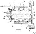
- FIG. 1 appended heretois a copy of FIG. 1 of Japanese patent application published under number JPH09245658, describing a plasma source. Only certain elements of the drawing will be described hereafter. Reference will be made hereafter to the Japanese patent application for more complete explanations.
- the plasma source shown in this drawingcomprises a plasma chamber 1 having a quarter wave antenna 6 arranged therein. Antenna 6 is isolated from the enclosure of plasma chamber 1 at its base by an isolator 2 . The free end of antenna 6 is located opposite a perforated electrode 8 . An input 4 allows gas to be introduced into the low-pressure enclosure of chamber 1 .
- the antennais excited by a high-frequency electromagnetic field and a plasma 5 foil's in chamber 1 at the locations where the electromagnetic field is maximum, as indicated by a cloud of points.
- Permanent magnets 3are arranged around the enclosure of plasma chamber 1 , to confine the plasma. Charges of the plasma are capable of being extracted through an opening or extraction grid 14 .
- antenna 6is described as having a lifetime from two to three hours, which is imputed to the fact that antenna 6 is submitted to a spraying, as well as the walls of enclosure 1 . It is specified that it is thus necessary to regularly change antenna 6 and to clean plasma chamber 1 . Accordingly, it is necessary to regularly take out the plasma source from the vacuum enclosure where it is used, which causes relatively long maintenance and vacuum restoration operations.
- an embodimentprovides a plasma source comprising a quarter wave antenna located in a cylindrical enclosure provided with an opening opposite the end of the antenna, wherein: the diameter of the antenna is in the range from one third to one quarter of the inner diameter of the enclosure, the distance between the end of the antenna and the opening is in the range from 2 ⁇ 3 to 5/3 of the diameter of the antenna.
- the inner diameter of the enclosureis in the order of 10 mm.
- the inner diameter of the enclosureis 10 mm
- the diameter of the antennais in the range from 2.5 to 3.3 mm
- the distance between the end of the antenna and the openingis in the range from 1.5 to 5.5 mm.
- the openingis a circular opening having a diameter in the range from 1 ⁇ m to the inner diameter of the enclosure.
- the openingis an extraction grid.
- the excitation frequency of the antennais 2.45 GHz.
- An embodimentprovides an extensive plasma source comprising an assembly of plasma sources such as those previously described, arranged side by side.
- FIG. 1previously described, is a cross-section view of a plasma source and is a copy of FIG. 1 of patent application JPH09245658;
- FIGS. 2A to 2Cshow plasma chambers provided with antennas having different diameters
- FIGS. 3A and 3Bare diagrams showing the average energy E radiated by the antenna in various areas according to diameter d of the antenna.
- FIG. 4is a simplified front view of an embodiment of a plasma source.
- the same elementshave been designated with the same reference numerals in the different drawings. For clarity, only those steps and elements which are useful to the understanding of the described embodiments have been shown and are detailed.
- the plasma source elements surrounding the plasma chambersuch as, in particular, a gas inlet, permanent magnets, connections of high-frequency signals and extraction electrodes, are not shown.
- FIGS. 2A to 2Care cross-section views of cylindrical plasma chambers 100 , all identical, having quarter wave antennas 102 of different diameters arranged therein.
- Quarter wave antennameans an antenna having a length approximately equal to one quarter of the wavelength of the excitation signal of the antenna.
- Each plasma chamber 100comprises an opening or extraction grid 104 through which ions of the plasma may be extracted.
- a surface 105delimits a plasma-forming region.
- a plasma-forming regioncorresponds to the area surrounding the antenna where the electromagnetic field has a sufficiently high value to enable to form the plasma. This value may for example be in the order of 10 4 V/m.
- Region 106is located on the side of opening or extraction grid 104 .
- Region 106here called useful region, contains a plasma which will be called useful plasma, that is, the plasma from which ions can be extracted to form an ion source.
- Region 108is located around antenna 102 along at least part of its length.
- Region 108here called useless region, contains a plasma which will be called useless plasma.
- the useless plasmacannot be extracted from the plasma source, and thus has no useful role but appears to be the cause of the degradation of antenna 102 described in patent application JPH09245658.
- the inventorshave thus attempted to maximize the useful plasma volume while decreasing the useless plasma volume. To achieve this, the inventors have studied the incidence of the diameter of antenna 102 of a plasma chamber 100 on such useful and useless plasma regions.
- plasma chambers 100 having an inner diameter equal to 10 mmare considered as an example.
- antenna 102has a 1-mm diameter. This corresponds to the dimensions of the antenna and of the plasma chamber illustrated in the above-mentioned Japanese patent application.
- antenna 102has a 3-mm diameter.
- Useless region 108has a smaller volume than in the case of FIG. 2A , which results in a decreased degradation.
- Useless region 106however keeps a similar volume.
- antenna 102has a 6-mm diameter.
- Useless region 108has a further decreased volume. However, the volume of useless region 106 is also decreased.
- FIGS. 3A and 3Bare diagrams respectively showing the energy E stored in useful region 106 and in useless region 108 , according to diameter d of antenna 102 , for a same radiated power having a 5-W intensity at a 2.45-GHz frequency.
- the energy E stored in useful region 106for diameters d of antenna 102 in the range from 1 to 3 mm, is approximately constant, and close to 6.10 ⁇ 11 J. It can also be observed that, for diameters d in the range from 3 to 6 mm, the energy E stored in useful region 106 markedly decreases to reach a substantially half value, close to 3.10 ⁇ 11 J for a diameter d of the antenna 102 of 6 mm.
- an increase in the diameter of the antennacauses a decrease in the volume of useless region 108 , that is, a decrease in the quantity of useless plasma likely to deteriorate antenna 102 .
- useless region 106contains a substantially constant quantity of useful plasma for diameters of antenna 102 approximately in the range from 1 to 3 mm.
- An advantageous diameter of antenna 102thus is a diameter which enables to keep as large a volume as possible of useful region 106 while reducing as much as possible the volume of useless region 108 .
- an advantageous diameter of the antennais approximately 3 mm, for example, in the range from 2.5 to 3.3 mm, for an inner diameter of plasma chamber 100 of 10 mm. This corresponds to a diameter of a plasma source in the range from one quarter to one third of the inner diameter of the plasma chamber.
- FIG. 4is a simplified cross-section view of an embodiment of a plasma chamber 200 .
- Plasma chamber 200comprises a cylindrical enclosure 202 .
- a quarter wave antenna 204is arranged in enclosure 202 .
- the base of antenna 204is isolated from the enclosure by an isolator 206 .
- Enclosure 202comprises an opening 208 opposite the end of antenna 204 .
- Opening 208is, in this example, a circular opening. Opening 208 may also be an extraction grid.
- the inner diameter d 1 of the enclosureis 10 mm in this example.
- an optimal value of diameter d of antenna 204is in the range from one quarter to one third of inner diameter d 1 of the enclosure, that is, approximately from 2.5 to 3.3 mm.
- Distance l between the end of antenna 204 and opening 208has a value for example in the range from 2 ⁇ 3 to 5/3 of the diameter of antenna 204 , that is, here in the range from 1.5 to 5.5 mm.
- diameter d 2 of opening 208 in the example of FIG. 4has a diameter approximately equal to diameter d of antenna 208 , for example, in the range from 4 ⁇ 5 to 6/5 of diameter d of antenna 204 .
- the inner diameter d 1 of the plasma chamberis here described as having a 10-mm value. This diameter may be selected differently.
- the diameter of opening 208may vary between 1 ⁇ m and inner diameter d 1 of the enclosure.
- Such plasma sourcesmay be associated to form an extended plasma source.
Landscapes
- Physics & Mathematics (AREA)
- Engineering & Computer Science (AREA)
- Plasma & Fusion (AREA)
- Electromagnetism (AREA)
- Spectroscopy & Molecular Physics (AREA)
- Chemical & Material Sciences (AREA)
- Combustion & Propulsion (AREA)
- Plasma Technology (AREA)
- Electron Sources, Ion Sources (AREA)
Abstract
Description
Claims (8)
Applications Claiming Priority (4)
| Application Number | Priority Date | Filing Date | Title |
|---|---|---|---|
| FR1750978AFR3062770B1 (en) | 2017-02-06 | 2017-02-06 | SOURCE OF PLASMA |
| FR1750978 | 2017-02-06 | ||
| FR17/50978 | 2017-02-06 | ||
| PCT/FR2017/053798WO2018142036A1 (en) | 2017-02-06 | 2017-12-21 | Plasma source |
Publications (2)
| Publication Number | Publication Date |
|---|---|
| US20190394866A1 US20190394866A1 (en) | 2019-12-26 |
| US10798810B2true US10798810B2 (en) | 2020-10-06 |
Family
ID=58547698
Family Applications (1)
| Application Number | Title | Priority Date | Filing Date |
|---|---|---|---|
| US16/480,063ActiveUS10798810B2 (en) | 2017-02-06 | 2017-12-21 | Plasma source |
Country Status (9)
| Country | Link |
|---|---|
| US (1) | US10798810B2 (en) |
| EP (1) | EP3578014B1 (en) |
| JP (1) | JP6847267B2 (en) |
| KR (1) | KR102526862B1 (en) |
| CN (1) | CN110383957B (en) |
| DK (1) | DK3578014T3 (en) |
| FR (1) | FR3062770B1 (en) |
| PL (1) | PL3578014T3 (en) |
| WO (1) | WO2018142036A1 (en) |
Families Citing this family (1)
| Publication number | Priority date | Publication date | Assignee | Title |
|---|---|---|---|---|
| FR3136104A1 (en) | 2022-05-30 | 2023-12-01 | Polygon Physics | Electron beam device for surface treatment |
Citations (6)
| Publication number | Priority date | Publication date | Assignee | Title |
|---|---|---|---|---|
| FR2480552A1 (en) | 1980-04-10 | 1981-10-16 | Anvar | PLASMA GENERATOR |
| US5361737A (en) | 1992-09-30 | 1994-11-08 | West Virginia University | Radio frequency coaxial cavity resonator as an ignition source and associated method |
| WO1998035379A1 (en) | 1997-01-23 | 1998-08-13 | The Regents Of The University Of California | Atmospheric-pressure plasma jet |
| US7103460B1 (en)* | 1994-05-09 | 2006-09-05 | Automotive Technologies International, Inc. | System and method for vehicle diagnostics |
| US20070095823A1 (en)* | 2005-10-27 | 2007-05-03 | Sedlmayr Steven R | Microwave nucleon-electron-bonding spin alignment and alteration of materials |
| US8664862B2 (en)* | 2008-10-17 | 2014-03-04 | Centre National De La Recherche Scientifique | Low-power gaseous plasma source |
Family Cites Families (7)
| Publication number | Priority date | Publication date | Assignee | Title |
|---|---|---|---|---|
| DE3023055A1 (en)* | 1979-07-12 | 1981-02-05 | Emi Ltd | ANTENNA |
| JPH09245658A (en) | 1996-03-12 | 1997-09-19 | Nissin Electric Co Ltd | Plasma generating mechanism utilizing ecr resonance by permanent magnet |
| CN100388559C (en)* | 2005-12-29 | 2008-05-14 | 上海交通大学 | Self-reconfiguring plasmonic antenna |
| ES2688300T3 (en)* | 2007-11-06 | 2018-10-31 | Creo Medical Limited | Applicator for plasma sterilization by microwave |
| KR101012345B1 (en)* | 2008-08-26 | 2011-02-09 | 포항공과대학교 산학협력단 | Low Power Portable Microwave Plasma Generator |
| US20110248002A1 (en)* | 2010-04-13 | 2011-10-13 | General Electric Company | Plasma generation apparatus |
| EP2928011B1 (en)* | 2014-04-02 | 2020-02-12 | Andrew Wireless Systems GmbH | Microwave cavity resonator |
- 2017
- 2017-02-06FRFR1750978Apatent/FR3062770B1/ennot_activeExpired - Fee Related
- 2017-12-21USUS16/480,063patent/US10798810B2/enactiveActive
- 2017-12-21EPEP17832280.6Apatent/EP3578014B1/enactiveActive
- 2017-12-21KRKR1020197025109Apatent/KR102526862B1/enactiveActive
- 2017-12-21WOPCT/FR2017/053798patent/WO2018142036A1/ennot_activeCeased
- 2017-12-21JPJP2019563692Apatent/JP6847267B2/enactiveActive
- 2017-12-21CNCN201780085783.XApatent/CN110383957B/enactiveActive
- 2017-12-21PLPL17832280Tpatent/PL3578014T3/enunknown
- 2017-12-21DKDK17832280.6Tpatent/DK3578014T3/enactive
Patent Citations (8)
| Publication number | Priority date | Publication date | Assignee | Title |
|---|---|---|---|---|
| FR2480552A1 (en) | 1980-04-10 | 1981-10-16 | Anvar | PLASMA GENERATOR |
| US4609808A (en)* | 1980-04-10 | 1986-09-02 | Agence Nationale De Valorisation De La Rechere (Anvar) | Plasma generator |
| US5361737A (en) | 1992-09-30 | 1994-11-08 | West Virginia University | Radio frequency coaxial cavity resonator as an ignition source and associated method |
| US7103460B1 (en)* | 1994-05-09 | 2006-09-05 | Automotive Technologies International, Inc. | System and method for vehicle diagnostics |
| WO1998035379A1 (en) | 1997-01-23 | 1998-08-13 | The Regents Of The University Of California | Atmospheric-pressure plasma jet |
| US5961772A (en)* | 1997-01-23 | 1999-10-05 | The Regents Of The University Of California | Atmospheric-pressure plasma jet |
| US20070095823A1 (en)* | 2005-10-27 | 2007-05-03 | Sedlmayr Steven R | Microwave nucleon-electron-bonding spin alignment and alteration of materials |
| US8664862B2 (en)* | 2008-10-17 | 2014-03-04 | Centre National De La Recherche Scientifique | Low-power gaseous plasma source |
Also Published As
| Publication number | Publication date |
|---|---|
| FR3062770B1 (en) | 2019-03-29 |
| EP3578014B1 (en) | 2020-10-28 |
| CN110383957B (en) | 2021-09-17 |
| CN110383957A (en) | 2019-10-25 |
| FR3062770A1 (en) | 2018-08-10 |
| PL3578014T3 (en) | 2021-05-31 |
| JP2020506526A (en) | 2020-02-27 |
| US20190394866A1 (en) | 2019-12-26 |
| JP6847267B2 (en) | 2021-03-24 |
| KR20190109749A (en) | 2019-09-26 |
| WO2018142036A1 (en) | 2018-08-09 |
| EP3578014A1 (en) | 2019-12-11 |
| DK3578014T3 (en) | 2020-11-30 |
| KR102526862B1 (en) | 2023-04-27 |
Similar Documents
| Publication | Publication Date | Title |
|---|---|---|
| US6803585B2 (en) | Electron-cyclotron resonance type ion beam source for ion implanter | |
| US7863582B2 (en) | Ion-beam source | |
| US9153405B2 (en) | Ion source device and ion beam generating method | |
| US20070176709A1 (en) | Method and apparatus for producing plasma | |
| US8698400B2 (en) | Method for producing a plasma beam and plasma source | |
| US9330889B2 (en) | Plasma generation device with microstrip resonator | |
| US9215789B1 (en) | Hybrid plasma source | |
| KR102862264B1 (en) | Ion source device with adjustable plasma density | |
| US7493869B1 (en) | Very large area/volume microwave ECR plasma and ion source | |
| RU2480858C2 (en) | High-current source of multicharge ions based on plasma of electronic-cyclotronic resonant discharge retained in open magnetic trap | |
| US8664862B2 (en) | Low-power gaseous plasma source | |
| US10798810B2 (en) | Plasma source | |
| US6835048B2 (en) | Ion pump having secondary magnetic field | |
| US11127578B2 (en) | Ion guiding device and related method | |
| JP2015534214A (en) | Apparatus for generating plasma that is axially high from a gaseous medium by electron cyclotron resonance (ECR) | |
| RU2246035C9 (en) | Ion engine | |
| KR101397646B1 (en) | Integrated microwave waveguide with impedance transition | |
| RU2649911C1 (en) | High-current source of ion beams based on of electron-cyclotron resonance discharge plasma held in open magnetic trap | |
| US10818469B2 (en) | Cylindrical shaped arc chamber for indirectly heated cathode ion source | |
| KR20020004934A (en) | Plasma source of linear beam ions | |
| US9368313B1 (en) | Electronic amplifier device | |
| CN109479369B (en) | Plasma source and plasma processing apparatus | |
| Guzilov | 6 kW L-band pulsed MBK with broad frequency band of 15% | |
| US9837240B1 (en) | Relativistic magnetron with no physical cathode | |
| JP7255952B2 (en) | ion beam source |
Legal Events
| Date | Code | Title | Description |
|---|---|---|---|
| FEPP | Fee payment procedure | Free format text:ENTITY STATUS SET TO UNDISCOUNTED (ORIGINAL EVENT CODE: BIG.); ENTITY STATUS OF PATENT OWNER: SMALL ENTITY | |
| FEPP | Fee payment procedure | Free format text:ENTITY STATUS SET TO SMALL (ORIGINAL EVENT CODE: SMAL); ENTITY STATUS OF PATENT OWNER: SMALL ENTITY | |
| AS | Assignment | Owner name:POLYGON PHYSICS, FRANCE Free format text:ASSIGNMENT OF ASSIGNORS INTEREST;ASSIGNOR:SORTAIS, PASCAL;REEL/FRAME:050456/0103 Effective date:20190827 | |
| STPP | Information on status: patent application and granting procedure in general | Free format text:PUBLICATIONS -- ISSUE FEE PAYMENT VERIFIED | |
| STCB | Information on status: application discontinuation | Free format text:ABANDONMENT FOR FAILURE TO CORRECT DRAWINGS/OATH/NONPUB REQUEST | |
| STPP | Information on status: patent application and granting procedure in general | Free format text:PUBLICATIONS -- ISSUE FEE PAYMENT VERIFIED | |
| STCF | Information on status: patent grant | Free format text:PATENTED CASE | |
| MAFP | Maintenance fee payment | Free format text:PAYMENT OF MAINTENANCE FEE, 4TH YR, SMALL ENTITY (ORIGINAL EVENT CODE: M2551); ENTITY STATUS OF PATENT OWNER: SMALL ENTITY Year of fee payment:4 | |
| AS | Assignment | Owner name:CAMECA, FRANCE Free format text:ASSIGNMENT OF ASSIGNORS INTEREST;ASSIGNOR:POLYGON PHYSICS;REEL/FRAME:071626/0244 Effective date:20241001 |