US10794632B2 - Vented cover plate for an array of syringes - Google Patents
Vented cover plate for an array of syringesDownload PDFInfo
- Publication number
- US10794632B2 US10794632B2US16/073,835US201716073835AUS10794632B2US 10794632 B2US10794632 B2US 10794632B2US 201716073835 AUS201716073835 AUS 201716073835AUS 10794632 B2US10794632 B2US 10794632B2
- Authority
- US
- United States
- Prior art keywords
- cover plate
- protuberances
- extensions
- containers
- tub
- Prior art date
- Legal status (The legal status is an assumption and is not a legal conclusion. Google has not performed a legal analysis and makes no representation as to the accuracy of the status listed.)
- Expired - Fee Related, expires
Links
Images


Classifications
- F—MECHANICAL ENGINEERING; LIGHTING; HEATING; WEAPONS; BLASTING
- F26—DRYING
- F26B—DRYING SOLID MATERIALS OR OBJECTS BY REMOVING LIQUID THEREFROM
- F26B5/00—Drying solid materials or objects by processes not involving the application of heat
- F26B5/04—Drying solid materials or objects by processes not involving the application of heat by evaporation or sublimation of moisture under reduced pressure, e.g. in a vacuum
- F26B5/06—Drying solid materials or objects by processes not involving the application of heat by evaporation or sublimation of moisture under reduced pressure, e.g. in a vacuum the process involving freezing
- A—HUMAN NECESSITIES
- A61—MEDICAL OR VETERINARY SCIENCE; HYGIENE
- A61J—CONTAINERS SPECIALLY ADAPTED FOR MEDICAL OR PHARMACEUTICAL PURPOSES; DEVICES OR METHODS SPECIALLY ADAPTED FOR BRINGING PHARMACEUTICAL PRODUCTS INTO PARTICULAR PHYSICAL OR ADMINISTERING FORMS; DEVICES FOR ADMINISTERING FOOD OR MEDICINES ORALLY; BABY COMFORTERS; DEVICES FOR RECEIVING SPITTLE
- A61J1/00—Containers specially adapted for medical or pharmaceutical purposes
- A61J1/14—Details; Accessories therefor
- A61J1/16—Holders for containers
- A—HUMAN NECESSITIES
- A61—MEDICAL OR VETERINARY SCIENCE; HYGIENE
- A61J—CONTAINERS SPECIALLY ADAPTED FOR MEDICAL OR PHARMACEUTICAL PURPOSES; DEVICES OR METHODS SPECIALLY ADAPTED FOR BRINGING PHARMACEUTICAL PRODUCTS INTO PARTICULAR PHYSICAL OR ADMINISTERING FORMS; DEVICES FOR ADMINISTERING FOOD OR MEDICINES ORALLY; BABY COMFORTERS; DEVICES FOR RECEIVING SPITTLE
- A61J1/00—Containers specially adapted for medical or pharmaceutical purposes
- A61J1/14—Details; Accessories therefor
- A61J1/20—Arrangements for transferring or mixing fluids, e.g. from vial to syringe
- A61J1/2096—Combination of a vial and a syringe for transferring or mixing their contents
- A—HUMAN NECESSITIES
- A61—MEDICAL OR VETERINARY SCIENCE; HYGIENE
- A61J—CONTAINERS SPECIALLY ADAPTED FOR MEDICAL OR PHARMACEUTICAL PURPOSES; DEVICES OR METHODS SPECIALLY ADAPTED FOR BRINGING PHARMACEUTICAL PRODUCTS INTO PARTICULAR PHYSICAL OR ADMINISTERING FORMS; DEVICES FOR ADMINISTERING FOOD OR MEDICINES ORALLY; BABY COMFORTERS; DEVICES FOR RECEIVING SPITTLE
- A61J3/00—Devices or methods specially adapted for bringing pharmaceutical products into particular physical or administering forms
- A61J3/02—Devices or methods specially adapted for bringing pharmaceutical products into particular physical or administering forms into the form of powders
- A—HUMAN NECESSITIES
- A61—MEDICAL OR VETERINARY SCIENCE; HYGIENE
- A61K—PREPARATIONS FOR MEDICAL, DENTAL OR TOILETRY PURPOSES
- A61K38/00—Medicinal preparations containing peptides
- A61K38/04—Peptides having up to 20 amino acids in a fully defined sequence; Derivatives thereof
- A61K38/08—Peptides having 5 to 11 amino acids
- A61K38/09—Luteinising hormone-releasing hormone [LHRH], i.e. Gonadotropin-releasing hormone [GnRH]; Related peptides
- A—HUMAN NECESSITIES
- A61—MEDICAL OR VETERINARY SCIENCE; HYGIENE
- A61M—DEVICES FOR INTRODUCING MEDIA INTO, OR ONTO, THE BODY; DEVICES FOR TRANSDUCING BODY MEDIA OR FOR TAKING MEDIA FROM THE BODY; DEVICES FOR PRODUCING OR ENDING SLEEP OR STUPOR
- A61M5/00—Devices for bringing media into the body in a subcutaneous, intra-vascular or intramuscular way; Accessories therefor, e.g. filling or cleaning devices, arm-rests
- A61M5/008—Racks for supporting syringes or needles
- A—HUMAN NECESSITIES
- A61—MEDICAL OR VETERINARY SCIENCE; HYGIENE
- A61M—DEVICES FOR INTRODUCING MEDIA INTO, OR ONTO, THE BODY; DEVICES FOR TRANSDUCING BODY MEDIA OR FOR TAKING MEDIA FROM THE BODY; DEVICES FOR PRODUCING OR ENDING SLEEP OR STUPOR
- A61M5/00—Devices for bringing media into the body in a subcutaneous, intra-vascular or intramuscular way; Accessories therefor, e.g. filling or cleaning devices, arm-rests
- A61M5/178—Syringes
- B—PERFORMING OPERATIONS; TRANSPORTING
- B65—CONVEYING; PACKING; STORING; HANDLING THIN OR FILAMENTARY MATERIAL
- B65D—CONTAINERS FOR STORAGE OR TRANSPORT OF ARTICLES OR MATERIALS, e.g. BAGS, BARRELS, BOTTLES, BOXES, CANS, CARTONS, CRATES, DRUMS, JARS, TANKS, HOPPERS, FORWARDING CONTAINERS; ACCESSORIES, CLOSURES, OR FITTINGS THEREFOR; PACKAGING ELEMENTS; PACKAGES
- B65D51/00—Closures not otherwise provided for
- B65D51/16—Closures not otherwise provided for with means for venting air or gas
- F—MECHANICAL ENGINEERING; LIGHTING; HEATING; WEAPONS; BLASTING
- F26—DRYING
- F26B—DRYING SOLID MATERIALS OR OBJECTS BY REMOVING LIQUID THEREFROM
- F26B25/00—Details of general application not covered by group F26B21/00 or F26B23/00
- F26B25/001—Handling, e.g. loading or unloading arrangements
- F26B25/003—Handling, e.g. loading or unloading arrangements for articles
Definitions
- the present disclosurerelates generally to methods and systems for handling delivery containers, such as syringes. More specifically, the present disclosure relates to methods and systems for filling, sterilizing, and handling delivery containers, and for enabling certain process including, but not limited to, lyophilization of contents provided within one or more delivery containers.
- Organic compounds, and more specifically pharmaceuticalsare generally more stable when they exist as a solid or powder than when they exist in solution.
- the shelf-life of a pharmaceutical stored in solutionis generally shorter than the shelf-life of the pharmaceutical stored as a solid or powder. Since many pharmaceuticals are stored for extended periods of time before use, it is advantageous to have these pharmaceuticals remain active over the extended period of time. It is therefore desirable to store pharmaceuticals, over an extended period of time, as a solid or powder. This includes pharmaceuticals that are ultimately reconstituted as a solution before administration.
- the lyophilized pharmaceuticali.e., medication
- a diluentcan be added to the syringe for reconstitution of the medication just prior to administration.
- the medicationcan then be administered from the syringe directly to the patient.
- lyophilizationtypically results in the solution “popping” or “bumping” when there is a residual amount of solvent remaining. This can result in solvent and pharmaceutical being displaced outside the syringe. In addition, the popping can result in cross contamination of adjacent syringes in the array.
- lyophilizationis performed directly in a syringe, a significant amount of solution containing the pharmaceutical can be displaced outside the syringe. Accordingly, one cannot be certain whether any such pharmaceutical has been displaced outside the syringe and therefore the amount of pharmaceutical remaining inside the syringe after lyophilization may not be sufficiently accurate or precise. Thus, the syringe and the contents therein must be recycled or discarded since the amount of pharmaceutical remaining in the syringe cannot be adequately ascertained for proper administration.
- Known devicesgenerally rely on an interaction between an inner diameter of a syringe barrel and an outer diameter of a protuberance of a cover plate to provide a temporary cover for syringes, tubes, or other devices during processing, such as a lyophilization process.
- weightis an important consideration as providing a cover plate with insufficient mass will enable the cover plate to move or be displaced too easily, while a cover plate with excessive mass may apply excessive force upon the syringe(s) and prevent venting or escape of lyophilized content, particularly if the device has been warped due to autoclaving, use, age, etc.
- Embodiments of the present disclosureprovide a cover plate suitable for use to cover one or more delivery containers (e.g., syringes) during filling and lyophilization processes.
- the cover plates of the present disclosureinclude a lid region and one or more protuberances which project substantially perpendicularly from the lid region. The one or more protuberances are adapted to fit in one or more delivery containers.
- the cover platepermits the escape of vapor from the one or more delivery containers during the lyophilization process.
- the cover plateprevents the escape of lyophilizate from the one or more delivery containers during the lyophilization process.
- Devices, methods and systems of the present disclosurecontemplate a syringe nest provided within or in connection with a tub, such as Hypak® or Steripak® configuration of prepackaged syringes in a tub, as sold by Becton, Dickinson & Company or the TopPac® device available from Schott®.
- a syringe nestprovided within or in connection with a tub, such as Hypak® or Steripak® configuration of prepackaged syringes in a tub, as sold by Becton, Dickinson & Company or the TopPac® device available from Schott®.
- Embodiments of the present disclosurealso provide a system for lyophilizing a pharmaceutical solution, and ultimately the lyophilized product.
- the systemincludes one or more delivery containers suitable for containing the pharmaceutical solution.
- the systemalso includes a cover plate as shown and described herein.
- Embodiments of the present disclosurealso provide systems for lyophilizing a pharmaceutical solution including one or more apparatus and one or more delivery containers. At least one of the one or more delivery containers contains the pharmaceutical solution.
- the systemalso includes a cover plate of the present invention that covers the one or more delivery containers during the lyophilization process.
- Embodimentsalso include a delivery system comprising the at least one or more delivery containers containing the lyophilized pharmaceutical product or “lyophilizate” (e.g., after lyophilization is complete), and which also includes a cover plate of the present invention that covers the one or more delivery containers.
- Embodiments of the present disclosurealso provide methods for lyophilizing a solution. Such methods include, for example, depositing the solution in one or more delivery containers, covering the one or more delivery containers with a cover plate of the present invention, and lyophilizing the solution that includes the pharmaceutical.
- the cover plateallows pharmaceutical solutions to be lyophilized, and enables at least one of pressure, vapor, and gas to escape from the delivery container during a lyophilization process and while preventing cross contamination of adjacent syringes.
- the cover plateallows pharmaceutical solutions to be lyophilized while the amount of lyophilizate remaining inside the delivery containers is sufficiently ascertainable.
- Embodiments of the present disclosureprovide cover plates or restrictor plates used to cover one or more delivery containers during a lyophilization process.
- the cover plates of the present disclosureallow for the lyophilization of a solution in a delivery container whereby the solution and the lyophilizate remains inside the delivery container.
- no significant amount of solution or lyophilizateis displaced from a delivery container.
- the amount of lyophilizate remaining inside the delivery containeris sufficiently ascertainable.
- cover plates of the present disclosureprevent cross-contamination of adjacent syringes in the array.
- the cover platesensure that the venting during lyophilization is repeatedly and reliably sufficient such that meltback of the lyophilized product cakes due to occlusion of the syringes by the cover plate is substantially or entirely prevented.
- Lyophilizationrefers to the removal of solvent from a frozen state by sublimation. Lyophilization is accomplished by freezing a solution below its melting point and then manipulating the temperature and pressure to provide sublimation. Precise control of temperature and pressure permits drying from the frozen state without product melt-back. In practical applications, the process is accelerated and more precisely controlled under reduced pressure conditions. Lyophilization or freeze drying is a process in which water is removed from a product after it is frozen and placed under a vacuum, allowing the ice to change directly from solid to vapor without passing through a liquid phase. The process generally consists of three separate, unique, and interdependent processes; freezing, primary drying (sublimation), and secondary drying (desorption).
- a cover platecomprising a base portion and at least one protuberance extending therefrom.
- the protuberancespreferably comprise a conical or frustoconical shape with a first end proximal to the base portion and a second end opposite thereto.
- the first ends of the protuberancescomprise a contact area for the cover plate where the contact plate is supported on or otherwise in contact with an open end of a syringe barrel.
- the first ends of the protuberancescomprise raised vent features wherein the raised vent features comprise support structures and/or contact areas for supporting the weight of the cover plate while allowing for one or more gaps or vents between an upper end of the syringe barrel(s) and the cover plate structure.
- one or more extensionsare provided on a cover plate and wherein the extensions are not formed directly on the protuberance(s).
- certain embodiments of the present disclosurecontemplate the provision of stand-off features or extensions that are provided distally or spaced apart from the protuberances, and wherein the protuberances are prevented from fully occluding an open end of delivery containers.
- lyophilizategenerally refers to the solid, powder or granular material remaining after lyophilization.
- the solid, powder or granular materialis essentially free of solvent.
- cover plates of the present disclosurecan be used to lyophilize a solution containing a pharmaceutical in a delivery container.
- Suitable pharmaceuticalinclude substances capable of prevention an infection systemically in an animal or human, or locally at the defect site, for example, antibacterial agents such as penicillin, cephalosporins, bacitracin, tetracycline, doxycycline, gentamycin, quinolines, neomycin, clindamycin, kanamycin, and metronidazole; anti-inflammatory agents such as hydrocortisone, and prednisone; antiparasitic agent such as quinacrine, chloroquine, and vidarbine; antifungal agents such as nystatin; antiviral agents such as acyclovir, ribarivin, and interferons; analgesic agents such as salicylic acid, acetaminophen, ibuprofen, naproxen, piroxicam, flurbiprof
- Suitable pharmaceuticalsinclude substances, or metabolic precursors thereof, which are capable of promoting growth and survival of cells and tissues or augmenting the functioning of cells.
- Suitable compounds capable of promoting growth and survival of cells and tissues or augmenting the functioning of cellsinclude a nerve growth promoting substance, such as a ganglioside or a nerve growth factor; a hard or soft tissue growth promoting agent, such as fibronectin (FN), human growth hormone (HGH), a colony stimulating factor, bone morphogenic protein, platelet-derived growth factor (PDGF), insulin-derived growth factor (IGF-I, IGF-II), transforming growth factor-alpha (TGF- ⁇ ), transforming growth factor- ⁇ (TGF- ⁇ ), epidermal growth factor (EGF), fibroblast growth factor (FGF), interleukin-1 (IL-1), and prostaglandins such as PGE1, PGE2 and PGD2; and an osteoinductive agent or bone growth promoting substance such a bone chips or demineralized bone material.
- Suitable pharmaceutical agentsinclude antine
- hormonessuch as progesterone, testosterone, follicle stimulating hormone (FSH) (used for birth control and fertility-enhancement), insulin, and somatotropins
- antihistaminessuch as diphenhydramine and chlorphencramine
- cardiovascular agentssuch as digitalis, nitroglycerine, papaverine and streptokinase
- anti-ulcer agentssuch as cimetidine hydrochloride, and isopropamide iodide
- bronchodilatorssuch as metaprotemal sulfate and aminophylline
- vasodilatorssuch as theophylline, niacin and minoxidil
- central nervous system agentssuch as tranquilizers, ⁇ -adrenergic blocking agents, and dopamine
- antipsychotic agentssuch as risperidone and olanzapine
- narcotic antagonistssuch as naltrexone, naloxone and buprenorphine.
- Suitable excipientsinclude ionic and non-ionic (amphoteric) surfactants (e.g., polysorbates, cremophores and tyloxopols), bulking agents (e.g., sodium phosphates, potassium phosphates, citric acid, tartaric acid, gelatins, and carbohydrates such as dextrose, mannitol and dextran), and lyoprotectants (e.g., glucose, catalase, maltose, maltotriose and maltohexose).
- ionic and non-ionic (amphoteric) surfactantse.g., polysorbates, cremophores and tyloxopols
- bulking agentse.g., sodium phosphates, potassium phosphates, citric acid, tartaric acid, gelatins, and carbohydrates such as dextrose, mannitol and dextran
- lyoprotectantse.g., glucose, catalase, maltos
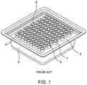
- FIG. 1is a front perspective view of a syringe nest and associated tub.
- FIG. 2is a detailed perspective view of a syringe nest and associated tub.
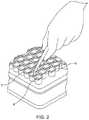
- FIG. 3is a perspective view of a tub, syringe nest and cover plate.
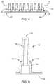
- FIG. 4is a side elevation view of a cover plate according to one embodiment of the present disclosure.
- FIG. 5is a cross-sectional elevation view of a cover plate according to the embodiment of FIG. 5 .
- Cover plates of the present disclosurecan be constructed from any suitable material.
- the material, or combination of materialsis preferably resistant to the temperature and pressure changes that exist during the lyophilization process.
- the materialis preferably durable, inexpensive, and reusable. Suitable materials include, but are not limited to plastics, TEFLON®, rubber, fiberglass, glass, and any combination thereof.
- Plasticis one preferable material for making the cover plate, as it is relatively light, durable, easy to use and relatively inexpensive.
- a syringe nest or rack 2is provided within a tub 4 .
- the syringe nest 2comprises a plurality of wells 6 for receiving syringes 7 , the syringes 7 comprising an open end 8 of a barrel portion.
- the open end 8comprises an opening that is generally exposed and adapted to receive a plunger rod (for example) after filling and/or sterilization process of the syringes are complete.
- FIG. 1depicts a syringe nest 2 with a plurality of syringes 7 disposed therein and wherein the open ends 8 of the syringes 7 are exposed to an outside environment.
- FIG. 2is a detailed perspective view of the system of FIG. 1 , wherein syringes 7 comprise an open end 8 . As shown, the open ends 8 allow access to an interior portion of a syringe barrel for various operations including, but not limited to, filling and lyophilization.
- FIG. 3is a perspective view of a syringe storage system or assembly comprising a syringe nest or rack 2 in combination with a tub 4 and a cover plate 12 .
- the cover plate 12comprises a plurality of protuberances 14 .
- the number and geometry of the protuberances 14preferably correspond to the number of wells provided in the syringe nest 2 .
- the cover plate 12as shown and described in more detail herein, generally comprises a cover plate for placing in contact and communication with the syringe nest 2 and associated syringes.
- the cover plate 12comprises a device that is adapted to rest on the syringe nest 2 and/or the plurality of syringes.
- the plateis not fastened or securely connected to the syringes or the syringe nest, but rests on the syringes or syringe nest under the force of gravity.
- a restrictor plateis provided comprising one or more fasteners to securely connect the plate to the syringe nest 2 or the tub 4 .
- FIG. 4is a front elevation view of a cover plate 12 in accordance with one embodiment of the present disclosure.
- the cover plate 12comprises a plurality of protuberances 14 extending from a base portion 16 .
- the base portion 16preferably comprises a rectangular and substantially planar base.
- the base portion 16extends outwardly beyond the protuberances 14 to provide a flange 17 extending around a perimeter or a portion of the perimeter of the base portion 16 .
- the protuberancesfurther comprise a first portion 15 and a second portion 18 .
- the first portions 15 and the second portions 18 of the protuberancespreferably comprise frustoconical members wherein the smallest outer diameter of the second portions 18 is greater than the largest outer diameter of the first portions 15 .
- the spacing or gaps between the extensionscomprise gaps or vents 30 (see FIG. 6 ) to allow gas and vapor to escape from the delivery container(s) during a lyophilization procedure, for example.
- the extensions provided in FIG. 4comprise a plurality of rectangular extensions extending from the second portions 18 and along an outer surface of the first portions 15 , it will be recognized that the extensions 20 may comprise any number of shapes, geometries, orientations, positions, etc. and still constitute features within the scope of the present disclosure.
- a void space, or spacing between the extensions 20provide vent features or fluid flow paths to allow gas to flow between and/or around the extensions 20 and therefore escape a delivery container in which the gas is stored or formed. Accordingly, the extensions 20 are contemplated as comprising extensions of any shape, size, position, etc.
- a protuberanceis provided with one or more flutes or recesses such that the protuberance rests in and/or on a delivery container and vapor or gas is allowed to escape from the delivery container and the restrictor plate through the flute(s) or recess(es).
- the flutesare contemplated as comprising slots or depressions in the sidewall(s) of the protuberances, wherein the sidewall of the protuberances contact the syringe barrel, and the flutes extend above and below the rim or lip of the syringe barrel to allow for egress of lyophilized contents.
- the flutesmay be of various shape including, for example, oval, circular, tear-drop shaped, etc.
- FIG. 5is a cross-sectional elevation view of a single protuberance 14 extending from a base portion 16 of a cover plate 12 , and taken through a center-line of the protuberance 14 .
- the protuberance 14comprises a first portion 15 and a second portion 18 . At least a portion of the first portion 15 is adapted to extend into an internal volume of a delivery container.
- the external surface and distal end 19 of the protuberance 14serve to cover and trap lyophilizate within an interior volume of a delivery container, while the second portion 18 and extensions 20 allow for the escape of gas and material necessary to the completion of a lyophilization process, or similar process.
- the cover platecomprises between 1 to about 300, 1 to about 200, 50 to about 150 or, preferably, about 75 to about 125 protuberances 14 .
- the protuberancesserve as a non air-tight stopper, plug or cap over a delivery container, thereby preventing the escape of lyophilizate from the delivery container during lyophilization.
- suitable protuberancescan catch lyophilizate that contacts the protuberance 14 during lyophilization.
- a suitable protuberance 14prevents lyophilizate from one delivery container from being introduced into another delivery container during lyophilization, thereby contaminating the contents of one delivery container with the contents of another delivery container.
- a suitable protuberance 14permits lyophilization to proceed by allowing vapor to pass from the interior of the delivery container to the exterior of the delivery container during lyophilization.
- the protuberances 14preferably fit within an opening 8 of the delivery container 7 to prevent the escape of lyophilizate from the delivery container 7 and to allow vapor to pass from the interior of the delivery container 7 to the exterior of the delivery container 7 during lyophilization.
- the protuberance 14can have any suitable shape.
- the protuberance 14can assume any suitable shape which generally corresponds with or is received within the shape of the opening 8 of the delivery container 7 , so long as the protuberance 14 cooperates with the opening 8 of the delivery container 7 .
- the protuberance 14may be shaped in any suitable manner provided it caps or plugs the opening 8 of the delivery container 7 and permits the passage of vapor during lyophilization. As such, the shape of the protuberance 14 can depend upon the shape of the opening 8 of the delivery container 7 .
- the protuberance 14can be spherically shaped, conically shaped, frustoconically shaped or cylindrically shaped.
- the cylindrically shaped protuberance 14can be tapered.
- the protuberance 14can be tapered from a first end of the protuberance proximal to the base portion 16 to a second end of the protuberance provided distally therefrom and adapted to be inserted into a delivery container.
- the protuberance(s) 14can be tapered from the lowest point vertically on the protuberance 14 after the cover plate 12 is placed atop a tub.
- the protuberance(s)comprise a length as small as hundredths of an inch or as large as several inches, depending upon the size and depth of delivery containers. Generally, the longer the protuberances 14 , the more firmly in place they will keep the cover plate 12 relative to the delivery containers 8 during lyophilization. In one embodiment, a length of each protuberance 14 is between about 1.0 inch and about 2.0 inches, and more preferably is about 1.4 inches to about 1.6 inches.
- the suitable length of the protuberance 14can typically depend upon the length of the delivery containers and the amount of contents in the delivery containers. Preferably, the suitable length of the protuberance 14 will minimize or lessen the occurrence of the contents of the delivery containers 7 from obtaining sufficient kinetic energy to be ejected out of the delivery containers 7 . The suitable length of the protuberance 14 will minimize or lessen this occurrence by extending within about 0.5 inch, within about 0.25 inch, or within about 0.1 inch of the contents of the delivery containers 8 .
- the spacing and positioning of the protuberances 14are provided to correspond to the spacing and positioning of wells or delivery containers 7 to which the cover plate 12 is designed to cooperate or mate with. Accordingly, this spacing or positioning can be varied.
- a distance between axial centers of adjacent protuberances in the same rowcan be about 0.5 inch to about 0.9 inch, and more specifically can be about 0.6 inch to about 0.7 inch.
- the distance horizontally between axial centers of the nearest two protuberances 30 in adjacent rowscan be about 0.25 inch to about 0.5 inch, and more specifically can be about 0.3 inch to about 0.4 inch.
- the distance horizontally between axial centers of the nearest two protuberances 30 in adjacent rowscan be about 0.4 inch to about 0.9 inch, and more specifically can be about 0.6 inch to about 0.7 inch.
- each of the protuberances 14comprise a plurality of extensions 20 distributed about a circumference of the protuberance.
- four extensions 20are provided on each protuberance 14 . It will be recognized, however, that the number, type, and/or location of the extensions may be various without deviating from the scope and spirit of the present invention.
- the cover plate 12 of the present disclosureprovides a reliable system and method for venting during a lyophilization procedure, wherein the cover plate's ability to vent contents housed within a delivery container is not substantially altered or affected by age, sterilization processes, and other factors known to affect the size, shape and integrity of a cover plate.
- the extensions 20 as shown and described hereinprovide a novel arrangement for providing desired venting properties, and wherein such venting properties are not substantially degraded by minor changes in the size, shape, hardness, etc. of the cover plate, which are known to vary over time in existing devices.
- the extensions 20are distributed and spaced-apart to provide vents 30 between adjacent extensions 20 .
- FIG. 7is a perspective view of a cover plate according to one embodiment of the present disclosure.
- the cover plate 12comprises a plurality of protuberances 14 extending from a base portion 16 .
- the base portion 16preferably comprises a rectangular and substantially planar base.
- the base portion 16extends outwardly beyond the protuberances 14 to provide a flange extending around a perimeter or a portion of the perimeter of the base portion 16 .
- the cover plate 12 of FIG. 7further comprises a plurality of extensions in the form of posts 40 provided on the flange 17 .
- the posts 40are operable to provide a stand-off height between the cover plate 12 and a rack and/or tub (not shown in FIG. 7 ).
- the posts 40comprise a height with a first end provided on the flange 17 and a second end comprising a free end.
- the second endis operable to contact at least one of a rack and a tub, and limit an amount, distance, or extent in which the protuberances 14 are allowed to extend into delivery containers when the cover plate is applied or positioned on the delivery containers.
- a stand-off heightis provided wherein the protuberances 14 are prevented from fulling extending into and therefore occluding the delivery containers. Accordingly, an annular gap is provided between each of the protuberances and a corresponding delivery container.
- the annular gapsserve as vent features to allow for escape of matter during lyophilization and sublimation.
- the posts 40are provided at each of the four corners of the cover plate 12 to provide stability. It will be recognized, however, that the posts and similar stand-off features may be provided at various different positions on the plate 12 . Additionally, although four posts 40 are shown in FIG. 7 , various numbers of posts are contemplated in alternative embodiments of the present disclosure.
- Delivery containers as disclosed and described hereinmay include any receptacle in which a pharmaceutical can be lyophilized.
- the delivery containersmay comprise ampules, vials, or syringes.
- Syringesare specifically suitable for lyophilizing pharmaceuticals whose ultimate use will be administration from a syringe.
- the pharmaceuticalcan be reconstituted, if necessary, in the syringe in which the pharmaceutical was lyophilized.
- syringesare especially suitable for lyophilizing an injectable pharmaceutical (i.e., medication), since the medication is ultimately administered from the syringe.
- the syringecan be manufactured from any suitable material. Suitable materials are those materials that are resistant to the temperature and pressure changes that exist during the lyophilization process. The material can be durable and inexpensive. Suitable materials include plastics, glass, and any combination thereof.
- the syringecan be manufactured from plastic.
- Plastic syringesare generally stronger than glass syringes.
- the increased strength of plasticresults in a more durable syringe.
- the increased durabilityallows for a safer syringe as a plastic syringe will not break as easily upon administration as compared to a glass syringe. As such, fewer health care professionals will become injured while reconstituting and administering injectable medications in a plastic syringe as compared to a glass syringe.
- plastic syringesDue to the increased strength of plastic syringes, the bore size of plastic syringes is routinely larger than those of comparable glass syringes, thereby decreasing the force required to use the plastic syringe. This is especially useful when reconstituting an injectable medication with a very viscous diluent or for syringe-to-syringe reconstitution. See, U.S. patent application Ser. No. 09/405,463 filed on Sep. 24, 1999.
- the syringecan be disposable or can be reusable.
- Disposable syringesare commercially available and are usually constructed from plastic or glass. Disposable syringes are popular due to their convenience and because they are relatively inexpensive.
- a suitable disposable plastic syringe of the present inventionis manufactured by Becton Dickinson & Company in what is known as a “Hypak” configuration and is disclosed in U.S. Pat. No. 4,758,230, for example.
- the solution containing the pharmaceuticalcan be cooled to a frozen solid prior to lyophilization.
- the solutioncan be cooled by any suitable cooling means (e.g., convention, conduction or radiation). Specifically, the solution can be cooled by convection.
- a partial vacuumis applied to the lyophilizing apparatus to provide a partial vacuum within the lyophilizing apparatus (i.e., within the inside of the delivery container and on the outside of the delivery container).
- the partial vacuumcan be applied to the solution, in the frozen state, until essentially all of the solvent is removed (i.e., to dryness).
- the tubcan be removed from the lyophilization apparatus.
- the cover plate 12can be removed from the delivery container 7 and examined for any retained lyophilizate. If the protuberances 14 of the cover plate 12 contains any lyophilizate, each delivery container 8 from which the lyophilizate originated can be discarded or recycled and the lyophilizate can be recycled or discarded. If any pharmaceutical leaves a delivery container and is captured on the restrictor plate, the amount of lyophilized pharmaceutical remaining in the delivery container is unknown. Thus, any delivery container losing any lyophilizate captured by the cover plate can be discarded or recycled. Accordingly, the cover plate is removed from on top of the delivery container and examined for any retained lyophilizate. If the cover plate contains any lyophilizate, each delivery container from which the lyophilizate originated can be discarded or recycled.
- the opening 8 of any undiscarded delivery container 7can be sealed for storage.
- the delivery container 7can be sealed with any suitable sealing device known for sealing delivery containers 7 .
- the proximal opening of the syringe barrelcan be sealed with the plunger of the syringe.
- FIG. 7depicts a cover plate 12 comprising a plurality of posts 40 and a plurality of extensions 20 provided on the protuberances 14 .
- the posts 40comprise features that obviate the need for the depicted extensions 20 .
- methods of performing lyophilizationcomprise providing a cover plate with a plurality of protuberances as shown and described herein.
- lyophilization of leuprolide acetateis achieved by providing a solution containing leuprolide acetate in a solvent, e.g. water, prepared by mixing leuprolide acetate in water until dissolved.
- a solvente.g. water
- a tub of syringesis opened so the opening of the proximal end of each syringe is exposed.
- Leuprolide acetate solution with approximately 7.5 mg of leuprolide acetateis filled into each syringe by means of a pipette (for example) through the opening of the proximal end of each syringe.
- the procedureis repeated with three additional tubs of syringes into which leuprolide acetate solution with approximately 22.5, 30, or 45 mg of leuprolide acetate is filled.
- the tub containing the plurality of syringesis placed on a shelf of a lyophilizing apparatus.
- the syringesare then covered with a cover plate (see FIG. 6 , item 12 , for example).
- the shelf of the lyophilizing apparatusincludes a refrigerant circulating within the shelf to control temperature and to facilitate a conductive heat transfer between the shelf and tub. The temperature of the shelf is reduced to approximately ⁇ 50° C.
- the resultant quantity of lyophilized powdermay be varied providing a larger or smaller initial volume of the of the leuprolide acetate solution.
- the initial concentration of the solution of leuprolide acetate in watermay be varied. Variations of the quantities noted above may be provided to produce a different resultant quantity of lyophilized powder or to provide the same resultant quantity using different inputs while performing essentially the same method steps.
- the tubis removed from the lyophilizing apparatus.
- the cover plateis removed from the opening of the syringes.
- Each area of the covering plateis examined for captured lyophilizate and the syringes from which any such captured lyophilizate came are discarded.
- Plunger tipsare installed into the opening of the proximal end of the syringes, and plunger rods are screwed into the corresponding plunger tips.
- the syringesare now ready for reconstitution.
- syringeswere intentionally occluded to observe effects of restricting water vapor flow from the syringe during lyophilization.
- Syringeswere occluded by creating a vent through stoppered syringes using 5 ⁇ 8′′ needles of varied gauges.
- partial occlusionwas accomplished by piercing syringe stoppers with a 27 gauge needle (0.21 mm nominal ID), a 20 gauge needle (0.63 mm nominal ID), and a 16 gauge needle (1.2 mm nominal ID).
- the syringeswere filled with a leuprolide acetate solution by hand using a micropipette and were weight checked.
- the syringeswere loaded into tubs and were subjected to a lyophilization cycle such as those described herein. Meltback or failed lyophilization was observed in syringes that were occluded and lacked sufficient venting. Specifically, it was observed that it is desirable to have a vent or opening of at least approximately 1.0 mm 2 to facilitate proper lyophilization. It will be recognized, however, that the present disclosure is not limited to any particular minimum area for a vent feature. In certain embodiments, however, it is preferable to provide at least approximately 1.0 mm 2 of vent area between an otherwise covered or closed end of a delivery container that is subjected to a lyophilization process.
Landscapes
- Health & Medical Sciences (AREA)
- Engineering & Computer Science (AREA)
- Life Sciences & Earth Sciences (AREA)
- Veterinary Medicine (AREA)
- Public Health (AREA)
- General Health & Medical Sciences (AREA)
- Animal Behavior & Ethology (AREA)
- Pharmacology & Pharmacy (AREA)
- Mechanical Engineering (AREA)
- General Engineering & Computer Science (AREA)
- Medicinal Chemistry (AREA)
- Chemical & Material Sciences (AREA)
- Biomedical Technology (AREA)
- Hematology (AREA)
- Vascular Medicine (AREA)
- Anesthesiology (AREA)
- Heart & Thoracic Surgery (AREA)
- Endocrinology (AREA)
- Bioinformatics & Cheminformatics (AREA)
- Immunology (AREA)
- Proteomics, Peptides & Aminoacids (AREA)
- Epidemiology (AREA)
- Molecular Biology (AREA)
- Gastroenterology & Hepatology (AREA)
- Reproductive Health (AREA)
- Infusion, Injection, And Reservoir Apparatuses (AREA)
- Measurement Of The Respiration, Hearing Ability, Form, And Blood Characteristics Of Living Organisms (AREA)
- Drying Of Solid Materials (AREA)
- Closures For Containers (AREA)
- Medical Preparation Storing Or Oral Administration Devices (AREA)
Abstract
Description
Claims (19)
Priority Applications (1)
| Application Number | Priority Date | Filing Date | Title |
|---|---|---|---|
| US16/073,835US10794632B2 (en) | 2016-02-05 | 2017-02-03 | Vented cover plate for an array of syringes |
Applications Claiming Priority (3)
| Application Number | Priority Date | Filing Date | Title |
|---|---|---|---|
| US201662292119P | 2016-02-05 | 2016-02-05 | |
| PCT/US2017/016419WO2017136667A1 (en) | 2016-02-05 | 2017-02-03 | Vented cover plate for an array of syringes |
| US16/073,835US10794632B2 (en) | 2016-02-05 | 2017-02-03 | Vented cover plate for an array of syringes |
Publications (2)
| Publication Number | Publication Date |
|---|---|
| US20190041132A1 US20190041132A1 (en) | 2019-02-07 |
| US10794632B2true US10794632B2 (en) | 2020-10-06 |
Family
ID=59500488
Family Applications (1)
| Application Number | Title | Priority Date | Filing Date |
|---|---|---|---|
| US16/073,835Expired - Fee RelatedUS10794632B2 (en) | 2016-02-05 | 2017-02-03 | Vented cover plate for an array of syringes |
Country Status (10)
| Country | Link |
|---|---|
| US (1) | US10794632B2 (en) |
| EP (1) | EP3411647A4 (en) |
| AR (1) | AR107541A1 (en) |
| EA (1) | EA037154B1 (en) |
| GE (1) | GEP20217312B (en) |
| SG (1) | SG11201806437SA (en) |
| TW (1) | TWI725116B (en) |
| UA (1) | UA122170C2 (en) |
| UY (1) | UY37112A (en) |
| WO (1) | WO2017136667A1 (en) |
Cited By (1)
| Publication number | Priority date | Publication date | Assignee | Title |
|---|---|---|---|---|
| US11957790B1 (en)* | 2022-01-31 | 2024-04-16 | Thomas John Harkins, JR. | Combination lyophilization and dispensing syringe assembly and methods of using same |
Families Citing this family (7)
| Publication number | Priority date | Publication date | Assignee | Title |
|---|---|---|---|---|
| EA037154B1 (en) | 2016-02-05 | 2021-02-11 | Толмар Терапьютикс, Инк. | Vented cover plate for an array of syringes |
| USD908916S1 (en) | 2018-06-19 | 2021-01-26 | Tolmar Therapeutics, Inc. | Syringe restrictor plate |
| ES2802149B2 (en) | 2019-07-04 | 2022-01-11 | Univ Salamanca | DEVICE AND PROCEDURE FOR THE SIMULTANEOUS LYOPHILIZATION OF A PLURALITY OF BIOLOGICAL SAMPLES |
| EP4076578A4 (en)* | 2019-12-16 | 2023-12-27 | Merck Sharp & Dohme LLC | Pre-filled syringe stopper retainer and methods of using same |
| FR3114081B1 (en) | 2020-09-11 | 2022-08-19 | A Raymond Et Cie | DELIVERY TRAY AND PACKAGING SYSTEM FOR MEDICAL ITEMS |
| US12098018B2 (en) | 2021-01-15 | 2024-09-24 | Oyster Point Pharma, Inc. | Nesting structures for storage, transport, and assembly of drug dispensers and containers |
| CN115540528B (en)* | 2022-09-19 | 2023-11-10 | 陕西隆升中药科技有限公司 | Preparation process of traditional Chinese medicine decoction pieces |
Citations (81)
| Publication number | Priority date | Publication date | Assignee | Title |
|---|---|---|---|---|
| US3454178A (en) | 1966-01-10 | 1969-07-08 | Charles E Bender | Sterile cap for a freeze-drying container and method of freeze-drying materials under sterile conditions |
| US3810469A (en) | 1972-05-24 | 1974-05-14 | Ampoules Inc | Multiple compartment hypodermic devices |
| US4003713A (en) | 1975-08-14 | 1977-01-18 | Bowser Everett N | Multiple test tube evaporator |
| US4017597A (en) | 1974-10-30 | 1977-04-12 | Monsanto Company | Unitized solid phase immunoassay kit and method |
| US4060911A (en) | 1975-08-07 | 1977-12-06 | Behringwerke Aktiengesellschaft | Process for the preparation of a container closed under sterile conditions and containing lyophilized material |
| US4172457A (en) | 1977-10-06 | 1979-10-30 | American Hospital Supply Corporation | Plural component mixing system and method |
| US4250139A (en) | 1979-02-01 | 1981-02-10 | Collagen Corporation | Microwave sterilization of dry protein |
| US4286389A (en) | 1980-03-03 | 1981-09-01 | Ims Limited | Apparatus and method for lyophilizing aseptic substances |
| US4306357A (en) | 1978-06-05 | 1981-12-22 | Merck & Co., Inc. | Tamperproof container |
| US4501719A (en) | 1981-05-04 | 1985-02-26 | Marquest Medical Products, Inc. | Tray apparatus for freeze-drying biologicals having a predetermined unit dosage |
| US4521975A (en) | 1981-05-04 | 1985-06-11 | Marquest Medical Products, Inc. | Lyophilizing and forming biologicals having a predetermined unit dosage |
| US4729208A (en) | 1983-12-08 | 1988-03-08 | Michel Galy | Method and apparatus for preparing syringes containing a lyophile medicine |
| US4758230A (en) | 1986-02-20 | 1988-07-19 | Becton, Dickinson And Company | Syringe barrel assembly |
| US4829006A (en) | 1988-02-01 | 1989-05-09 | Difco Laboratories | Centrifugation vial and cluster tray |
| US4872572A (en) | 1987-12-24 | 1989-10-10 | Helvoet Pharma N.V. | Lyophilization stopper (case II) |
| US4874381A (en) | 1988-02-16 | 1989-10-17 | Arzheimittel Gmbh Apotheker Vetter & Co. Ravensburg | Hypodermic syringe |
| US4878597A (en) | 1988-03-24 | 1989-11-07 | Haast William E | Lyophilization containers |
| US4952208A (en) | 1987-07-21 | 1990-08-28 | Wasserburger Arzneimittelwerk Dr. Madaus Gmbh & Co. Kg | Injection syringe for medical purposes |
| US5000737A (en) | 1987-09-18 | 1991-03-19 | Program For Appropriate Technology In Health (Path) | Single use disposable syringe |
| US5002538A (en) | 1988-10-25 | 1991-03-26 | Johnson Johnnie M | Syringe adapter and method |
| US5005721A (en)* | 1987-05-08 | 1991-04-09 | Abbott Laboratories | Vial seal |
| US5080649A (en) | 1990-02-07 | 1992-01-14 | Arzneimittel Gmbh Apotheker Vetter & Co. Ravensburg | Dual-compartment hypodermic syringe |
| US5184450A (en) | 1991-02-15 | 1993-02-09 | Pasteur Merieux Serums Et Vaccins | Method of packaging freeze dried vaccines in syringes and plug for implementing the method |
| US5234529A (en) | 1991-10-10 | 1993-08-10 | Johnson Wayne L | Plasma generating apparatus employing capacitive shielding and process for using such apparatus |
| US5279608A (en) | 1990-12-18 | 1994-01-18 | Societe De Conseils De Recherches Et D'applications Scientifiques (S.C.R.A.S.) | Osmotic pumps |
| US5320603A (en) | 1991-08-21 | 1994-06-14 | Arzneimitel Gmbh Apotheker Vetter & Co. | Hypodermic syringe for lyophilized medicament |
| US5334162A (en) | 1993-03-15 | 1994-08-02 | Eli Lilly And Company | Cartridge assembly for a lyophilized compound forming a disposable portion of an injector pen and method for same |
| US5352756A (en) | 1992-02-13 | 1994-10-04 | Carlsberg A/S | Poly(ethylene or propylene glycol)-containing polymer |
| US5354562A (en) | 1992-01-21 | 1994-10-11 | Sri International | Process for preparing micronized polypeptide drugs |
| EP0664137A2 (en) | 1994-01-25 | 1995-07-26 | Becton, Dickinson and Company | Syringe and method for lyophilizing and reconstituting injectable medication |
| US5478946A (en) | 1989-06-21 | 1995-12-26 | Abbott Laboratories | Guanidino compounds as regulators of nitric oxide synthase |
| US5519984A (en)* | 1995-03-16 | 1996-05-28 | Mallinckrodt Medical, Inc. | Methods for packaging a pressure or vacuum sensitive product |
| US5542935A (en) | 1989-12-22 | 1996-08-06 | Imarx Pharmaceutical Corp. | Therapeutic delivery systems related applications |
| US5595760A (en) | 1994-09-02 | 1997-01-21 | Delab | Sustained release of peptides from pharmaceutical compositions |
| US5596814A (en) | 1995-11-06 | 1997-01-28 | W. L. Gore & Associates, Inc. | Vented vial stopper for processing freeze-dried products |
| US5611971A (en) | 1992-08-07 | 1997-03-18 | Takeda Chemical Industries, Ltd. | Production of microcapsules of water-soluble drugs |
| US5653693A (en) | 1991-09-10 | 1997-08-05 | Daiichi Pharmaceutical Co., Ltd. | Medicated syringe preparation |
| US5741463A (en) | 1993-04-19 | 1998-04-21 | Sanadi; Ashok Ramesh | Apparatus for preventing cross-contamination of multi-well test plates |
| US5770559A (en) | 1992-10-14 | 1998-06-23 | The Regents Of The University Of Colorado | Solubilization of pharmaceutical substances in an organic solvent and preparation of pharmaceutical powders using the same |
| US5779668A (en) | 1995-03-29 | 1998-07-14 | Abbott Laboratories | Syringe barrel for lyophilization, reconstitution and administration |
| US5803284A (en) | 1996-09-27 | 1998-09-08 | Becton Dickinson And Company | Sterile closure assembly for sealing a medicament container |
| US5807345A (en) | 1995-06-30 | 1998-09-15 | Abbott Laboratories | Luer cap for terminally sterilized syringe |
| US5819964A (en) | 1996-09-27 | 1998-10-13 | Becton Dickinson And Company | Lyophilization closure assembly for a medicament container for use during a lyophilization process |
| US5882603A (en) | 1997-10-15 | 1999-03-16 | Point Plastics Incorporated | Support rack for pipette tips |
| US5900422A (en) | 1994-12-22 | 1999-05-04 | Smithkline Beecham Corporation | Fibrinogen receptor antagonists |
| US5916526A (en) | 1995-08-11 | 1999-06-29 | Robbins Scientific Corporation | Compartmentalized multi-well container |
| US5945126A (en) | 1997-02-13 | 1999-08-31 | Oakwood Laboratories L.L.C. | Continuous microsphere process |
| US5958714A (en) | 1996-10-02 | 1999-09-28 | Safety Associates, Inc. | Test kits for determining at least two specific analytes in foods and other complex matrices |
| US5957314A (en) | 1996-04-09 | 1999-09-28 | Taisei Kako Co., Ltd. | Crown caps for drug containers |
| US6027694A (en) | 1996-10-17 | 2000-02-22 | Texperts, Inc. | Spillproof microplate assembly |
| US6033603A (en) | 1996-11-06 | 2000-03-07 | Bausch & Lomb Incorporated | Method and apparatus for separating contact lens mold sections |
| US6083761A (en) | 1996-12-02 | 2000-07-04 | Glaxo Wellcome Inc. | Method and apparatus for transferring and combining reagents |
| US6087324A (en) | 1993-06-24 | 2000-07-11 | Takeda Chemical Industries, Ltd. | Sustained-release preparation |
| US6090925A (en) | 1993-03-09 | 2000-07-18 | Epic Therapeutics, Inc. | Macromolecular microparticles and methods of production and use |
| US6096562A (en) | 1997-10-27 | 2000-08-01 | Nalge Nunc International Corporation | Multi-slide assembly including slide, frame and strip cap, and methods thereof |
| WO2000044641A2 (en) | 1999-02-01 | 2000-08-03 | Integrated Biosystems | Improved lyophilization apparatus and methods |
| US6106783A (en)* | 1998-06-30 | 2000-08-22 | Microliter Analytical Supplies, Inc. | Microplate assembly and closure |
| US6136273A (en)* | 1998-11-18 | 2000-10-24 | Matrix Technologies Corporation | Closure device for laboratory receptacles |
| US6164044A (en) | 1998-03-13 | 2000-12-26 | Becton Dickinson And Company | Method and apparatus for assembling and packaging medical devices |
| US6221854B1 (en) | 1996-03-05 | 2001-04-24 | Orquest, Inc. | Method of promoting bone growth with hyaluronic acid and growth factors |
| US6224883B1 (en) | 1995-10-30 | 2001-05-01 | Matrix Pharmaceutical, Inc. | Process and composition for therapeutic cisplatin (CDDP) |
| US6241949B1 (en) | 1999-08-17 | 2001-06-05 | Spectrumedix Corporation | Spill-resistant microtitre trays and method of making |
| WO2001047571A2 (en) | 1999-12-29 | 2001-07-05 | Regeneration Technologies, Inc. | System for reconstituting pastes and methods of using same |
| US6305413B1 (en) | 1999-02-19 | 2001-10-23 | Ultradent Products, Inc. | Mixing adaptor system |
| US20010037091A1 (en) | 1999-12-29 | 2001-11-01 | Wironen John F. | System for reconstituting pastes and methods of using same |
| US20010042317A1 (en) | 1998-11-12 | 2001-11-22 | Atrix Laboratories, Inc. | Process and delivery container for lyophilizing active agent |
| US6340589B1 (en) | 1999-07-23 | 2002-01-22 | Mj Research, Inc. | Thin-well microplate and methods of making same |
| US20020055708A1 (en) | 1999-09-24 | 2002-05-09 | Peterson Kenneth R. | Coupling syringe system and methods for obtaining a mixed composition |
| US6436351B1 (en) | 1998-07-15 | 2002-08-20 | Deltagen Research Laboratories, L.L.C. | Microtitre chemical reaction system |
| US20020114737A1 (en) | 2000-03-27 | 2002-08-22 | Atrix Laboratories, Inc. | Cover plate for use in lyophilization |
| US6455005B1 (en)* | 2000-02-02 | 2002-09-24 | Soltec, Inc. | Flexible septa closure plug mats for well plate mounted arrays of sample vials |
| US6776964B1 (en)* | 1999-09-08 | 2004-08-17 | Micronic B.V. | Sealing mat for closing reaction tubes |
| US20050048575A1 (en) | 2003-04-30 | 2005-03-03 | Coassin Peter J. | Multi-well plate providing a high-density storage and assay platform |
| US6890488B2 (en)* | 2001-06-22 | 2005-05-10 | Matrix Technologies, Inc. | Apparatus for sealing test tubes and the like |
| US6907679B2 (en)* | 1998-11-12 | 2005-06-21 | Qlt Usa, Inc. | Method for lyophilizing an active agent |
| WO2006045625A1 (en) | 2004-10-27 | 2006-05-04 | Glaxosmithkline Biologicals S.A. | Process for preparing a lyophilised material |
| WO2012042291A1 (en) | 2010-09-28 | 2012-04-05 | Becton Dickinson France S.A.S. | Packaging for cylindrical containers |
| USD700712S1 (en)* | 2011-09-07 | 2014-03-04 | ABgene Limited | PCR multiwell plate and cap mat assembly |
| WO2017136667A1 (en) | 2016-02-05 | 2017-08-10 | Tolmar Tharapeutics, Inc. | Vented cover plate for an array of syringes |
| USD804050S1 (en)* | 2015-02-03 | 2017-11-28 | ABgene Limited | Combined polymerase chain reaction multi-well plate and plate of caps |
| US9931635B1 (en)* | 2016-09-15 | 2018-04-03 | Pall Corporation | Cover for microplate of multiwell assembly and method of processing fluid sample |
- 2017
- 2017-02-03EAEA201891771Apatent/EA037154B1/enunknown
- 2017-02-03WOPCT/US2017/016419patent/WO2017136667A1/ennot_activeCeased
- 2017-02-03EPEP17748234.6Apatent/EP3411647A4/enactivePending
- 2017-02-03SGSG11201806437SApatent/SG11201806437SA/enunknown
- 2017-02-03UYUY0001037112Apatent/UY37112A/ennot_activeApplication Discontinuation
- 2017-02-03GEGEAP201714845Apatent/GEP20217312B/enunknown
- 2017-02-03TWTW106103628Apatent/TWI725116B/ennot_activeIP Right Cessation
- 2017-02-03UAUAA201809130Apatent/UA122170C2/enunknown
- 2017-02-03ARARP170100290Apatent/AR107541A1/enunknown
- 2017-02-03USUS16/073,835patent/US10794632B2/ennot_activeExpired - Fee Related
Patent Citations (89)
| Publication number | Priority date | Publication date | Assignee | Title |
|---|---|---|---|---|
| US3454178A (en) | 1966-01-10 | 1969-07-08 | Charles E Bender | Sterile cap for a freeze-drying container and method of freeze-drying materials under sterile conditions |
| US3810469A (en) | 1972-05-24 | 1974-05-14 | Ampoules Inc | Multiple compartment hypodermic devices |
| US4017597A (en) | 1974-10-30 | 1977-04-12 | Monsanto Company | Unitized solid phase immunoassay kit and method |
| US4060911A (en) | 1975-08-07 | 1977-12-06 | Behringwerke Aktiengesellschaft | Process for the preparation of a container closed under sterile conditions and containing lyophilized material |
| US4003713A (en) | 1975-08-14 | 1977-01-18 | Bowser Everett N | Multiple test tube evaporator |
| US4172457A (en) | 1977-10-06 | 1979-10-30 | American Hospital Supply Corporation | Plural component mixing system and method |
| US4306357A (en) | 1978-06-05 | 1981-12-22 | Merck & Co., Inc. | Tamperproof container |
| US4250139A (en) | 1979-02-01 | 1981-02-10 | Collagen Corporation | Microwave sterilization of dry protein |
| US4286389A (en) | 1980-03-03 | 1981-09-01 | Ims Limited | Apparatus and method for lyophilizing aseptic substances |
| US4501719A (en) | 1981-05-04 | 1985-02-26 | Marquest Medical Products, Inc. | Tray apparatus for freeze-drying biologicals having a predetermined unit dosage |
| US4521975A (en) | 1981-05-04 | 1985-06-11 | Marquest Medical Products, Inc. | Lyophilizing and forming biologicals having a predetermined unit dosage |
| US4729208A (en) | 1983-12-08 | 1988-03-08 | Michel Galy | Method and apparatus for preparing syringes containing a lyophile medicine |
| US4758230A (en) | 1986-02-20 | 1988-07-19 | Becton, Dickinson And Company | Syringe barrel assembly |
| US5005721A (en)* | 1987-05-08 | 1991-04-09 | Abbott Laboratories | Vial seal |
| US4952208A (en) | 1987-07-21 | 1990-08-28 | Wasserburger Arzneimittelwerk Dr. Madaus Gmbh & Co. Kg | Injection syringe for medical purposes |
| US5000737A (en) | 1987-09-18 | 1991-03-19 | Program For Appropriate Technology In Health (Path) | Single use disposable syringe |
| US4872572A (en) | 1987-12-24 | 1989-10-10 | Helvoet Pharma N.V. | Lyophilization stopper (case II) |
| US4829006A (en) | 1988-02-01 | 1989-05-09 | Difco Laboratories | Centrifugation vial and cluster tray |
| US4874381A (en) | 1988-02-16 | 1989-10-17 | Arzheimittel Gmbh Apotheker Vetter & Co. Ravensburg | Hypodermic syringe |
| US4878597A (en) | 1988-03-24 | 1989-11-07 | Haast William E | Lyophilization containers |
| US5002538A (en) | 1988-10-25 | 1991-03-26 | Johnson Johnnie M | Syringe adapter and method |
| US5478946A (en) | 1989-06-21 | 1995-12-26 | Abbott Laboratories | Guanidino compounds as regulators of nitric oxide synthase |
| US5542935A (en) | 1989-12-22 | 1996-08-06 | Imarx Pharmaceutical Corp. | Therapeutic delivery systems related applications |
| US5080649A (en) | 1990-02-07 | 1992-01-14 | Arzneimittel Gmbh Apotheker Vetter & Co. Ravensburg | Dual-compartment hypodermic syringe |
| US5279608A (en) | 1990-12-18 | 1994-01-18 | Societe De Conseils De Recherches Et D'applications Scientifiques (S.C.R.A.S.) | Osmotic pumps |
| US5184450A (en) | 1991-02-15 | 1993-02-09 | Pasteur Merieux Serums Et Vaccins | Method of packaging freeze dried vaccines in syringes and plug for implementing the method |
| US5320603A (en) | 1991-08-21 | 1994-06-14 | Arzneimitel Gmbh Apotheker Vetter & Co. | Hypodermic syringe for lyophilized medicament |
| US5653693A (en) | 1991-09-10 | 1997-08-05 | Daiichi Pharmaceutical Co., Ltd. | Medicated syringe preparation |
| US5234529A (en) | 1991-10-10 | 1993-08-10 | Johnson Wayne L | Plasma generating apparatus employing capacitive shielding and process for using such apparatus |
| US5354562A (en) | 1992-01-21 | 1994-10-11 | Sri International | Process for preparing micronized polypeptide drugs |
| US5352756A (en) | 1992-02-13 | 1994-10-04 | Carlsberg A/S | Poly(ethylene or propylene glycol)-containing polymer |
| US5611971A (en) | 1992-08-07 | 1997-03-18 | Takeda Chemical Industries, Ltd. | Production of microcapsules of water-soluble drugs |
| US5770559A (en) | 1992-10-14 | 1998-06-23 | The Regents Of The University Of Colorado | Solubilization of pharmaceutical substances in an organic solvent and preparation of pharmaceutical powders using the same |
| US6090925A (en) | 1993-03-09 | 2000-07-18 | Epic Therapeutics, Inc. | Macromolecular microparticles and methods of production and use |
| US5334162A (en) | 1993-03-15 | 1994-08-02 | Eli Lilly And Company | Cartridge assembly for a lyophilized compound forming a disposable portion of an injector pen and method for same |
| US5741463A (en) | 1993-04-19 | 1998-04-21 | Sanadi; Ashok Ramesh | Apparatus for preventing cross-contamination of multi-well test plates |
| US6087324A (en) | 1993-06-24 | 2000-07-11 | Takeda Chemical Industries, Ltd. | Sustained-release preparation |
| EP0664137A2 (en) | 1994-01-25 | 1995-07-26 | Becton, Dickinson and Company | Syringe and method for lyophilizing and reconstituting injectable medication |
| US5595760A (en) | 1994-09-02 | 1997-01-21 | Delab | Sustained release of peptides from pharmaceutical compositions |
| US5900422A (en) | 1994-12-22 | 1999-05-04 | Smithkline Beecham Corporation | Fibrinogen receptor antagonists |
| US5519984A (en)* | 1995-03-16 | 1996-05-28 | Mallinckrodt Medical, Inc. | Methods for packaging a pressure or vacuum sensitive product |
| US5779668A (en) | 1995-03-29 | 1998-07-14 | Abbott Laboratories | Syringe barrel for lyophilization, reconstitution and administration |
| US5807345A (en) | 1995-06-30 | 1998-09-15 | Abbott Laboratories | Luer cap for terminally sterilized syringe |
| US5916526A (en) | 1995-08-11 | 1999-06-29 | Robbins Scientific Corporation | Compartmentalized multi-well container |
| US6224883B1 (en) | 1995-10-30 | 2001-05-01 | Matrix Pharmaceutical, Inc. | Process and composition for therapeutic cisplatin (CDDP) |
| US5596814A (en) | 1995-11-06 | 1997-01-28 | W. L. Gore & Associates, Inc. | Vented vial stopper for processing freeze-dried products |
| US6221854B1 (en) | 1996-03-05 | 2001-04-24 | Orquest, Inc. | Method of promoting bone growth with hyaluronic acid and growth factors |
| US5957314A (en) | 1996-04-09 | 1999-09-28 | Taisei Kako Co., Ltd. | Crown caps for drug containers |
| US5803284A (en) | 1996-09-27 | 1998-09-08 | Becton Dickinson And Company | Sterile closure assembly for sealing a medicament container |
| US5819964A (en) | 1996-09-27 | 1998-10-13 | Becton Dickinson And Company | Lyophilization closure assembly for a medicament container for use during a lyophilization process |
| US5958714A (en) | 1996-10-02 | 1999-09-28 | Safety Associates, Inc. | Test kits for determining at least two specific analytes in foods and other complex matrices |
| US6027694A (en) | 1996-10-17 | 2000-02-22 | Texperts, Inc. | Spillproof microplate assembly |
| US6033603A (en) | 1996-11-06 | 2000-03-07 | Bausch & Lomb Incorporated | Method and apparatus for separating contact lens mold sections |
| US6083761A (en) | 1996-12-02 | 2000-07-04 | Glaxo Wellcome Inc. | Method and apparatus for transferring and combining reagents |
| US5945126A (en) | 1997-02-13 | 1999-08-31 | Oakwood Laboratories L.L.C. | Continuous microsphere process |
| US5882603A (en) | 1997-10-15 | 1999-03-16 | Point Plastics Incorporated | Support rack for pipette tips |
| US6096562A (en) | 1997-10-27 | 2000-08-01 | Nalge Nunc International Corporation | Multi-slide assembly including slide, frame and strip cap, and methods thereof |
| US6164044A (en) | 1998-03-13 | 2000-12-26 | Becton Dickinson And Company | Method and apparatus for assembling and packaging medical devices |
| US6189292B1 (en) | 1998-03-13 | 2001-02-20 | Becton Dickinson And Company | Method and apparatus for manufacturing, filling and packaging medical devices and medical containers |
| US6106783A (en)* | 1998-06-30 | 2000-08-22 | Microliter Analytical Supplies, Inc. | Microplate assembly and closure |
| US6436351B1 (en) | 1998-07-15 | 2002-08-20 | Deltagen Research Laboratories, L.L.C. | Microtitre chemical reaction system |
| US20010042317A1 (en) | 1998-11-12 | 2001-11-22 | Atrix Laboratories, Inc. | Process and delivery container for lyophilizing active agent |
| US9003676B2 (en) | 1998-11-12 | 2015-04-14 | Tolmar Therapeutics, Inc. | Method for lyophilizing an active agent |
| US6722054B2 (en)* | 1998-11-12 | 2004-04-20 | Atrix Laboratories, Inc. | Process and delivery container for lyophilizing active agent |
| US20150148752A1 (en) | 1998-11-12 | 2015-05-28 | Tolmar Therapeutics, Inc. | Article of manufacture containing lyophilized leuprolide acetate |
| US7467482B2 (en) | 1998-11-12 | 2008-12-23 | Qlt Usa, Inc. | Method for lyophilizing an active agent |
| US6907679B2 (en)* | 1998-11-12 | 2005-06-21 | Qlt Usa, Inc. | Method for lyophilizing an active agent |
| US6136273A (en)* | 1998-11-18 | 2000-10-24 | Matrix Technologies Corporation | Closure device for laboratory receptacles |
| WO2000044641A2 (en) | 1999-02-01 | 2000-08-03 | Integrated Biosystems | Improved lyophilization apparatus and methods |
| US6199297B1 (en)* | 1999-02-01 | 2001-03-13 | Integrated Biosystems, Inc. | Lyophilization apparatus and methods |
| US6305413B1 (en) | 1999-02-19 | 2001-10-23 | Ultradent Products, Inc. | Mixing adaptor system |
| US6340589B1 (en) | 1999-07-23 | 2002-01-22 | Mj Research, Inc. | Thin-well microplate and methods of making same |
| US6241949B1 (en) | 1999-08-17 | 2001-06-05 | Spectrumedix Corporation | Spill-resistant microtitre trays and method of making |
| US6776964B1 (en)* | 1999-09-08 | 2004-08-17 | Micronic B.V. | Sealing mat for closing reaction tubes |
| US20020055708A1 (en) | 1999-09-24 | 2002-05-09 | Peterson Kenneth R. | Coupling syringe system and methods for obtaining a mixed composition |
| US20010037091A1 (en) | 1999-12-29 | 2001-11-01 | Wironen John F. | System for reconstituting pastes and methods of using same |
| WO2001047571A2 (en) | 1999-12-29 | 2001-07-05 | Regeneration Technologies, Inc. | System for reconstituting pastes and methods of using same |
| US6455005B1 (en)* | 2000-02-02 | 2002-09-24 | Soltec, Inc. | Flexible septa closure plug mats for well plate mounted arrays of sample vials |
| US6566144B1 (en)* | 2000-03-27 | 2003-05-20 | Atrix Laboratories | Cover plate for use in lyophilization |
| US20020114737A1 (en) | 2000-03-27 | 2002-08-22 | Atrix Laboratories, Inc. | Cover plate for use in lyophilization |
| US6890488B2 (en)* | 2001-06-22 | 2005-05-10 | Matrix Technologies, Inc. | Apparatus for sealing test tubes and the like |
| EP1617886A1 (en) | 2003-03-17 | 2006-01-25 | QLT USA, Inc. | Method for lyophilizing an active agent |
| US20050048575A1 (en) | 2003-04-30 | 2005-03-03 | Coassin Peter J. | Multi-well plate providing a high-density storage and assay platform |
| WO2006045625A1 (en) | 2004-10-27 | 2006-05-04 | Glaxosmithkline Biologicals S.A. | Process for preparing a lyophilised material |
| WO2012042291A1 (en) | 2010-09-28 | 2012-04-05 | Becton Dickinson France S.A.S. | Packaging for cylindrical containers |
| USD700712S1 (en)* | 2011-09-07 | 2014-03-04 | ABgene Limited | PCR multiwell plate and cap mat assembly |
| USD804050S1 (en)* | 2015-02-03 | 2017-11-28 | ABgene Limited | Combined polymerase chain reaction multi-well plate and plate of caps |
| WO2017136667A1 (en) | 2016-02-05 | 2017-08-10 | Tolmar Tharapeutics, Inc. | Vented cover plate for an array of syringes |
| US9931635B1 (en)* | 2016-09-15 | 2018-04-03 | Pall Corporation | Cover for microplate of multiwell assembly and method of processing fluid sample |
Non-Patent Citations (42)
| Title |
|---|
| Extended European Search Report for European Patent Application No. 17748234.6, dated Aug. 28, 2019, 7 pages. |
| Extended Search Report for European Patent Application No. 15178699.3, dated Jun. 14, 2016 6 pages. |
| Intention to Grant for European Patent Application No. 04757460.3, dated Mar. 11, 2015 5 pages. |
| Intention to Grant for European Patent Application No. 15178699.3, dated Apr. 30, 2018 5 pages. |
| International Preliminary Report on Patentability for International (PCT) Patent Application No. PCT/US2004/007887, dated Oct. 6, 2005 7 pages. |
| International Preliminary Report on Patentability for International (PCT) Patent Application No. PCT/US2017/016419, dated Aug. 16, 2018 10 pages. |
| International Search Report and Written Opinion for International (PCT) Patent Application No. PCT/US2004/007887, dated Jul. 16, 2004 12 pages. |
| International Search Report issued by the United States Patent and Trademark Office for International Patent Application No. PCT/US2017/016419, dated Apr. 27, 2017, 4 pages. |
| Notice of Acceptance for Australia Patent Application No. 2004222346, dated Feb. 8, 2010 3 pages. |
| Notice of Acceptance for Australia Patent Application No. 2010201976, dated Jul. 12, 2012 4 pages. |
| Notice of Allowance for Canada Patent Application No. 2,519,367, dated Jul. 6, 2010 1 page. |
| Notice of Allowance for Japan Patent Application No. 2006-507209, dated May 11, 2011 3 pages. |
| Notice of Allowance for U.S. Appl. No. 10/391,480, dated Feb. 4, 2005 4 pages. |
| Notice of Allowance for U.S. Appl. No. 10/391,480, dated Jul. 22, 2004 4 pages. |
| Notice of Allowance for U.S. Appl. No. 11/099,919, dated Apr. 17, 2008 4 pages. |
| Notice of Allowance for U.S. Appl. No. 12/140,519, dated Dec. 5, 2014 9 pages. |
| Official Action (no English translation available) for Eurasian Patent Application No. 201891771, dated Oct. 10, 2019, 2 pages. |
| Official Action for Australia Patent Application No. 2004222346, dated Oct. 21, 2008 2 pages. |
| Official Action for Australia Patent Application No. 2010201976, dated Apr. 11, 2011 3 pages. |
| Official Action for Canada Patent Application No. 2,519,367, dated Apr. 30, 2008 3 pages. |
| Official Action for European Patent Application No. 04757460.3, dated Feb. 4, 2014 4 pages. |
| Official Action for European Patent Application No. 04757460.3, dated Jan. 12, 2011 4 pages. |
| Official Action for European Patent Application No. 04757460.3, dated Jan. 19, 2009 3 pages. |
| Official Action for European Patent Application No. 15178699.3, dated Aug. 2, 2017 4 pages. |
| Official Action for U.S. Appl. No. 10/391,480, dated Apr. 7, 2004 12 pages. |
| Official Action for U.S. Appl. No. 11/099,919, dated Aug. 22, 2006 10 pages. |
| Official Action for U.S. Appl. No. 11/099,919, dated Jan. 22, 2007 8 pages. |
| Official Action for U.S. Appl. No. 11/099,919, dated Jun. 14, 2007 8 pages. |
| Official Action for U.S. Appl. No. 11/099,919, dated Mar. 13, 2006 11 pages. |
| Official Action for U.S. Appl. No. 11/099,919, dated Nov. 21, 2007 9 pages. |
| Official Action for U.S. Appl. No. 11/099,919, dated Sep. 10, 2007 9 pages. |
| Official Action for U.S. Appl. No. 12/140,519, dated Jun. 7, 2013 15 pages. |
| Official Action for U.S. Appl. No. 12/140,519, dated Mar. 27, 2014 18 pages. |
| Official Action for U.S. Appl. No. 12/140,519, dated May 26, 2011 26 pages. |
| Official Action for U.S. Appl. No. 12/140,519, dated Nov. 14, 2011 21 pages. |
| Official Action for U.S. Appl. No. 12/140,519, dated Nov. 18, 2013 16 pages. |
| Official Action for U.S. Appl. No. 12/140,519, dated Oct. 15, 2010 22 pages. |
| Official Action for U.S. Appl. No. 12/140,519, dated Sep. 4, 2012 19 pages. |
| Official Action for U.S. Appl. No. 14/590,779, dated Oct. 7, 2015 9 pages. |
| Official Action with English Translation for Japan Patent Application No. 2006-507209, dated Aug. 16, 2010 3 pages. |
| Official Action with English Translation for Japan Patent Application No. 2006-507209, dated Nov. 26, 2009 6 pages. |
| Written Opinion issued by the United States Patent and Trademark Office for International Patent Application No. PCT/US2017/016419, dated Apr. 27, 2017, 8 pages. |
Cited By (2)
| Publication number | Priority date | Publication date | Assignee | Title |
|---|---|---|---|---|
| US11957790B1 (en)* | 2022-01-31 | 2024-04-16 | Thomas John Harkins, JR. | Combination lyophilization and dispensing syringe assembly and methods of using same |
| US20240148655A1 (en)* | 2022-01-31 | 2024-05-09 | Thomas John Harkins, JR. | Combination lyophilization and dispensing syringe assembly and methods of using same |
Also Published As
| Publication number | Publication date |
|---|---|
| TWI725116B (en) | 2021-04-21 |
| SG11201806437SA (en) | 2018-08-30 |
| EA037154B1 (en) | 2021-02-11 |
| US20190041132A1 (en) | 2019-02-07 |
| WO2017136667A1 (en) | 2017-08-10 |
| EP3411647A4 (en) | 2019-09-25 |
| EP3411647A1 (en) | 2018-12-12 |
| UA122170C2 (en) | 2020-09-25 |
| EA201891771A1 (en) | 2019-01-31 |
| TW201739671A (en) | 2017-11-16 |
| UY37112A (en) | 2017-07-31 |
| AR107541A1 (en) | 2018-05-09 |
| GEP20217312B (en) | 2021-11-10 |
Similar Documents
| Publication | Publication Date | Title |
|---|---|---|
| US10794632B2 (en) | Vented cover plate for an array of syringes | |
| US6566144B1 (en) | Cover plate for use in lyophilization | |
| EP1617886B1 (en) | Method for lyophilizing an active agent | |
| US6722054B2 (en) | Process and delivery container for lyophilizing active agent | |
| AU2001249498A1 (en) | Cover plate for use in lyophilization | |
| JP4638553B1 (en) | Manufacturing method and front stopper of two-chamber syringe | |
| HK1226680B (en) | Assembly and method for lyophilizing an active agent | |
| JP2721949B2 (en) | Holder for freeze-drying of the syringe body in a medicine container and syringe | |
| HK1226680A1 (en) | Assembly and method for lyophilizing an active agent |
Legal Events
| Date | Code | Title | Description |
|---|---|---|---|
| FEPP | Fee payment procedure | Free format text:ENTITY STATUS SET TO UNDISCOUNTED (ORIGINAL EVENT CODE: BIG.); ENTITY STATUS OF PATENT OWNER: LARGE ENTITY | |
| AS | Assignment | Owner name:TOLMAR THERAPEUTICS, INC., COLORADO Free format text:ASSIGNMENT OF ASSIGNORS INTEREST;ASSIGNORS:MCCANN, KEVIN STUART;BRINKMAN, HERBERT ROBERT;DOWNING, JOHN MILTON;SIGNING DATES FROM 20180810 TO 20180816;REEL/FRAME:046829/0890 | |
| STPP | Information on status: patent application and granting procedure in general | Free format text:DOCKETED NEW CASE - READY FOR EXAMINATION | |
| STPP | Information on status: patent application and granting procedure in general | Free format text:NON FINAL ACTION MAILED | |
| STPP | Information on status: patent application and granting procedure in general | Free format text:NON FINAL ACTION MAILED | |
| STPP | Information on status: patent application and granting procedure in general | Free format text:RESPONSE TO NON-FINAL OFFICE ACTION ENTERED AND FORWARDED TO EXAMINER | |
| STPP | Information on status: patent application and granting procedure in general | Free format text:NOTICE OF ALLOWANCE MAILED -- APPLICATION RECEIVED IN OFFICE OF PUBLICATIONS | |
| STCF | Information on status: patent grant | Free format text:PATENTED CASE | |
| AS | Assignment | Owner name:WELLS FARGO BANK, NATIONAL ASSOCIATION, AS ADMINISTRATIVE AGENT, COLORADO Free format text:SECURITY INTEREST;ASSIGNOR:TOLMAR THERAPEUTICS, INC.;REEL/FRAME:060762/0256 Effective date:20220805 | |
| AS | Assignment | Owner name:TOLMAR INC., COLORADO Free format text:MERGER;ASSIGNOR:TOLMAR THERAPEUTICS INC.;REEL/FRAME:062785/0849 Effective date:20221220 | |
| FEPP | Fee payment procedure | Free format text:MAINTENANCE FEE REMINDER MAILED (ORIGINAL EVENT CODE: REM.); ENTITY STATUS OF PATENT OWNER: LARGE ENTITY | |
| LAPS | Lapse for failure to pay maintenance fees | Free format text:PATENT EXPIRED FOR FAILURE TO PAY MAINTENANCE FEES (ORIGINAL EVENT CODE: EXP.); ENTITY STATUS OF PATENT OWNER: LARGE ENTITY | |
| STCH | Information on status: patent discontinuation | Free format text:PATENT EXPIRED DUE TO NONPAYMENT OF MAINTENANCE FEES UNDER 37 CFR 1.362 | |
| FP | Lapsed due to failure to pay maintenance fee | Effective date:20241006 |