US10793332B2 - System and method for palletless shipment of gas cylinder arrays - Google Patents
System and method for palletless shipment of gas cylinder arraysDownload PDFInfo
- Publication number
- US10793332B2 US10793332B2US15/969,787US201815969787AUS10793332B2US 10793332 B2US10793332 B2US 10793332B2US 201815969787 AUS201815969787 AUS 201815969787AUS 10793332 B2US10793332 B2US 10793332B2
- Authority
- US
- United States
- Prior art keywords
- tunnel
- subarray
- elements
- gas cylinders
- pillar
- Prior art date
- Legal status (The legal status is an assumption and is not a legal conclusion. Google has not performed a legal analysis and makes no representation as to the accuracy of the status listed.)
- Active, expires
Links
- 238000000034methodMethods0.000titleclaimsabstractdescription24
- 238000003491arrayMethods0.000titleabstractdescription6
- 238000004806packaging method and processMethods0.000claimsdescription8
- 239000011800void materialSubstances0.000claimsdescription8
- 230000001681protective effectEffects0.000claimsdescription2
- 239000003562lightweight materialSubstances0.000abstractdescription2
- 238000005299abrasionMethods0.000abstract1
- ATUOYWHBWRKTHZ-UHFFFAOYSA-NPropaneChemical compoundCCCATUOYWHBWRKTHZ-UHFFFAOYSA-N0.000description14
- 239000001294propaneSubstances0.000description7
- 230000008901benefitEffects0.000description3
- 238000012856packingMethods0.000description3
- 230000009172burstingEffects0.000description2
- 239000002655kraft paperSubstances0.000description2
- 239000000463materialSubstances0.000description2
- 238000012986modificationMethods0.000description2
- 230000004048modificationEffects0.000description2
- 239000000047productSubstances0.000description2
- 239000000853adhesiveSubstances0.000description1
- 230000001070adhesive effectEffects0.000description1
- 239000006227byproductSubstances0.000description1
- 238000010276constructionMethods0.000description1
- 239000002699waste materialSubstances0.000description1
Images


Classifications
- B—PERFORMING OPERATIONS; TRANSPORTING
- B65—CONVEYING; PACKING; STORING; HANDLING THIN OR FILAMENTARY MATERIAL
- B65D—CONTAINERS FOR STORAGE OR TRANSPORT OF ARTICLES OR MATERIALS, e.g. BAGS, BARRELS, BOTTLES, BOXES, CANS, CARTONS, CRATES, DRUMS, JARS, TANKS, HOPPERS, FORWARDING CONTAINERS; ACCESSORIES, CLOSURES, OR FITTINGS THEREFOR; PACKAGING ELEMENTS; PACKAGES
- B65D71/00—Bundles of articles held together by packaging elements for convenience of storage or transport, e.g. portable segregating carrier for plural receptacles such as beer cans or pop bottles; Bales of material
- B65D71/70—Trays provided with projections or recesses in order to assemble multiple articles, e.g. intermediate elements for stacking
- B65D71/72—Trays provided with projections or recesses in order to assemble multiple articles, e.g. intermediate elements for stacking formed by folding one or more blanks, the articles being inserted in openings in a wall
- B—PERFORMING OPERATIONS; TRANSPORTING
- B65—CONVEYING; PACKING; STORING; HANDLING THIN OR FILAMENTARY MATERIAL
- B65D—CONTAINERS FOR STORAGE OR TRANSPORT OF ARTICLES OR MATERIALS, e.g. BAGS, BARRELS, BOTTLES, BOXES, CANS, CARTONS, CRATES, DRUMS, JARS, TANKS, HOPPERS, FORWARDING CONTAINERS; ACCESSORIES, CLOSURES, OR FITTINGS THEREFOR; PACKAGING ELEMENTS; PACKAGES
- B65D71/00—Bundles of articles held together by packaging elements for convenience of storage or transport, e.g. portable segregating carrier for plural receptacles such as beer cans or pop bottles; Bales of material
- B65D71/0088—Palletisable loads, i.e. loads intended to be transported by means of a fork-lift truck
- B65D71/0092—Palletisable loads, i.e. loads intended to be transported by means of a fork-lift truck provided with one or more rigid supports, at least one dimension of the supports corresponding to a dimension of the load, e.g. skids
- B65D71/0096—Palletisable loads, i.e. loads intended to be transported by means of a fork-lift truck provided with one or more rigid supports, at least one dimension of the supports corresponding to a dimension of the load, e.g. skids the dimensions of the supports corresponding to the periphery of the load, e.g. pallets
- B—PERFORMING OPERATIONS; TRANSPORTING
- B65—CONVEYING; PACKING; STORING; HANDLING THIN OR FILAMENTARY MATERIAL
- B65B—MACHINES, APPARATUS OR DEVICES FOR, OR METHODS OF, PACKAGING ARTICLES OR MATERIALS; UNPACKING
- B65B17/00—Other machines, apparatus, or methods for packaging articles or materials
- B65B17/02—Joining articles, e.g. cans, directly to each other for convenience of storage, transport, or handling
- B—PERFORMING OPERATIONS; TRANSPORTING
- B65—CONVEYING; PACKING; STORING; HANDLING THIN OR FILAMENTARY MATERIAL
- B65B—MACHINES, APPARATUS OR DEVICES FOR, OR METHODS OF, PACKAGING ARTICLES OR MATERIALS; UNPACKING
- B65B61/00—Auxiliary devices, not otherwise provided for, for operating on sheets, blanks, webs, binding material, containers or packages
- B65B61/14—Auxiliary devices, not otherwise provided for, for operating on sheets, blanks, webs, binding material, containers or packages for incorporating, or forming and incorporating, handles or suspension means in packages
- B—PERFORMING OPERATIONS; TRANSPORTING
- B65—CONVEYING; PACKING; STORING; HANDLING THIN OR FILAMENTARY MATERIAL
- B65D—CONTAINERS FOR STORAGE OR TRANSPORT OF ARTICLES OR MATERIALS, e.g. BAGS, BARRELS, BOTTLES, BOXES, CANS, CARTONS, CRATES, DRUMS, JARS, TANKS, HOPPERS, FORWARDING CONTAINERS; ACCESSORIES, CLOSURES, OR FITTINGS THEREFOR; PACKAGING ELEMENTS; PACKAGES
- B65D71/00—Bundles of articles held together by packaging elements for convenience of storage or transport, e.g. portable segregating carrier for plural receptacles such as beer cans or pop bottles; Bales of material
- B65D71/02—Arrangements of flexible binders
- B65D71/04—Arrangements of flexible binders with protecting or supporting elements arranged between binder and articles or materials, e.g. for preventing chafing of binder
Definitions
- the present inventionrelates generally to the field of product packaging and shipment. More particularly, the invention involves systems and methods for packaging an array of gas cylinders for space-efficient and secure storage and shipment.
- a three-dimensional array of gas cylindersmay be formed from a plurality of vertically-stacked two-dimensional subarrays.
- Each subarrayis defined by a subset of gas cylinders which are laterally tightly disposed with respect to one another.
- Each gas cylindertypically includes an upper surface, a lower surface and a handle portion extending from its upper surface.
- Each subarrayhas at least two columns extending in a depth direction and at least three rows extending in a width direction.
- a pair of first elongated voidsextend through the array in the width direction at a first handle elevation.
- Each first elongated voidis bilaterally bounded by respective handle portions of the subarray below. It is also vertically bounded by the upper surface of the gas cylinders immediately below the void and the lower surfaces of the gas cylinders immediately above the void.
- Each of a pair of first tunnel elementsis disposed within a respective one of the first elongated voids and is configured to releasably receive a corresponding forklift tong.
- each gas cylinderincludes a foot portion extending from its lower surface
- the vertical stackingpreferably involves at least partial nested engagement of the handle portions of each lower subarray with the foot portions of the respective subarray immediately thereabove.
- Additional tunnel elementsmay be provided to allow a forklift to engage the system at various elevations in the array, and at various lateral angles with respect to the array.
- the key components of the systemmay be inexpensively formed from cardboard or similar recyclable, lightweight materials. Improved rigidity and weight distribution may be imparted to the system by way of vertically-oriented pillar elements configured to engage the tunnel elements.
- the pillar elementsmay also provide additional protection to the gas cylinders during shipment, by including flaps capable of shielding closely adjacent gas cylinders from rubbing against one another.
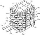
- FIG. 1is a diagrammatic perspective view of a package system in accordance with one non-limiting embodiment of the present invention
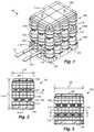
- FIG. 2is a diagrammatic side view of the embodiment depicted in FIG. 1 ;
- FIG. 3is a diagrammatic side view of the embodiment depicted in FIG. 1 ;
- FIG. 4is a diagrammatic cross-sectional view take along lines 4 - 4 in FIG. 2 ;
- FIG. 5is a diagrammatic cross-sectional view take along lines 5 - 5 in FIG. 3 ;
- FIG. 6is a diagrammatic magnified view of detail 6 in FIG. 4 , illustrating the partial receipt of the handle ring of a lower gas cylinder within the foot ring of the gas cylinder of the respective upper gas cylinder, as well as a second tunnel element disposed in the space lateral of the handle ring;
- FIG. 7is a diagrammatic is a magnified view of detail 7 in FIG. 4 , illustrating a flap member protectively disposed between weld lines of adjacent gas cylinders;
- FIG. 8is a diagrammatic is a magnified view of detail 8 in FIG. 5 , illustrating multiple flap members of a pillar element protectively disposed between weld lines of adjacent gas cylinders;
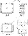
- FIG. 9is a diagrammatic plan view of a bottom tray element box blank in accordance with the system embodiment shown throughout the several FIGS;
- FIG. 10is a diagrammatic plan view of a cap element box blank in accordance with the system embodiment shown throughout the several FIGS;
- FIG. 11is a diagrammatic plan view of a pillar element box blank in accordance with the system embodiment shown throughout the several FIGS;
- FIG. 12is a diagrammatic plan view of a first tunnel element box blank in accordance with the system embodiment shown throughout the several FIGS;
- FIG. 13is a diagrammatic plan view of a second tunnel element box blank in accordance with the system embodiment shown throughout the several FIGS;
- FIG. 14is a diagrammatic perspective view of one embodiment of a pillar element
- FIG. 15is a diagrammatic side view of the pillar element of FIG. 14 ;
- FIG. 16is a further diagrammatic side view of the pillar element of FIG. 14 , but orthogonal to the side view of FIG. 15 ;
- FIG. 17is a diagrammatic end view of the pillar element of FIG. 14 ;
- FIG. 18is a diagrammatic perspective partially exploded view illustrating a multiplicity of pillar elements being inserted between a first subarray of gas cylinders placed in a bottom tray element;
- FIG. 19is a diagrammatic perspective partially exploded view illustrating a pair of first tunnel elements being inserted into first tunnel receiving apertures of respective pillar elements;
- FIG. 20is a diagrammatic perspective partially exploded view illustrating a pair of second tunnel elements being inserted into second tunnel receiving apertures of respective pillar elements, with a second subarray of gas cylinders having been placed on the first subarray;
- FIG. 21is a diagrammatic perspective partially exploded view illustrating a cap element being placed atop the upper ends of the pillar elements and the third subarray of gas cylinders, such that the handle rings of the top cylinders about the lateral perimeter of the assembly are snuggly received by the upper portion of the cap element;
- FIG. 22is a diagrammatic perspective view of the fully-assembled system of FIG. 1 , but shown without the securement straps;
- FIG. 23is a diagrammatic perspective view two systems in accordance with the present invention in vertically stacked configuration.
- FIG. 24is a diagrammatic flow chart representing steps comprised in one or more non-limiting examples of a method of packaging an array of gas cylinders for shipment.
- the following description of preferred embodimentsgenerally relates to systems and methods for pattetlessly shipping arrays of gas cylinders, such as propane tanks and the like.
- Embodiments of a system 100may comprise an array of gas cylinders 102 , a base tray element 104 , a cap element 106 , and at least a pair of first tunnel elements 110 .
- the base tray element 104may have corner portions 108 which are chamfered (as shown in FIGS. 1 and 8 for example), filleted or the like.
- Certain embodiments, such as the one illustrated for example in FIG. 1may comprise a pair of second tunnel elements 112 in place of or in addition to the pair of first tunnel elements 110 .
- first tunnel elements 110 and second tunnel elements 112may preferably be disposed orthogonally to one another, and may reside at different heights in the system 100 .
- the first and second tunnel elementsare each adapted to receive a respective tong of a forklift.
- embodiments of a system 100may preferably comprise pillar elements 126 .
- such pillar elements 126may preferably be configured for lateral disposition between four respective gas cylinders 102 .
- the pillar elements 126may include a plurality of flap members 130 , each being positionable between respective laterally-adjacent gas cylinders 102 to shield those cylinders (e.g., their weld lines 128 ) from destructively contacting one another during, for example, movement or transportation of the system 100 .
- the pillar elements 126may also include a first tunnel receiving aperture 132 and a second tunnel-receiving aperture 134 .
- the first tunnel receiving aperture 132may be configured to receive a first tunnel element 110 therethough, and the second tunnel aperture 134 may be configured to receive a second tunnel element 112 therethrough.
- the system 100when the system 100 is in its assembled form, it may be secured by way of packing straps 114 or the like.
- the assembled systemtypically has height 116 , depth 118 and width 120 .
- the handle portion (or “handle ring”) 122 of each lower gas cylinders 102may be preferably partially received by or “nested within” the foot ring 124 of the gas cylinder 102 directly thereabove. This results in vertical space savings in the system 100 .
- tunnel elements 110 and 112may extend throughout the assembly 100 . Further, as illustrated in FIGS.
- the tunnel elements 110 and 112may preferably non-obtrusively reside within the gaps defined between the handle rings 122 of laterally-adjacent gas cylinders 102 and between the vessel walls of vertically adjacent gas cylinders 102 .
- Particular embodiments of a system 100may be configured with only two levels of gas cylinders.
- either the first tunnel elements 110 or the second tunnel elements 112may not be included, and the shortened pillar elements 126 may correspondingly lack either the first tunnel apertures 132 or second tunnel apertures 134 .
- FIGS. 9-13what are illustrated are example box blanks which correspond to respective embodiments of a bottom tray element 104 , cap element 106 , pillar element 126 , first tunnel element 110 and second tunnel element 112 .
- Some or all of these componentsmay be formed of corrugated cardboard, such as double-walled, B-flute 275# bursting test with a Kraft finish, or an alternative material with similar performance characteristics.
- Such blankscan be folded about their fold lines or creases (shown in dashed lines in FIGS. 9-13 ), and the formed component may be secured in its operative configuration using tape, adhesive or the like.
- a system for palletless shipment of gas cylinder arrayspreferably comprises a three-dimensional array of gas cylinders 102 and a pair of first tunnel elements 110 .
- the arrayis formed from a plurality of vertically-stacked two-dimensional subarrays (see, for example, subarrays 136 a , 136 b and 136 c .
- Each such subarrayis defined by a subset of gas cylinders 102 laterally disposed with respect to one another.
- Each gas cylinder 102may include an upper surface 138 , a lower surface 140 and a handle portion 122 extending from the upper surface 138 .
- each subarraymay have at least two columns 142 extending in a depth direction 146 and at least three rows 144 extending in a width direction 148 .
- a pair of first elongated voids 150typically extend through the array, for example in the width direction 148 , at a first handle elevation 156 .
- Each of the first tunnel elements 110may be disposed within a respective one of the first elongated voids and configured to releasably receive a corresponding forklift tong 154 .
- each elongated void discussed hereinmay preferably be bilaterally bounded by at least respective handle portions 122 , and vertically bounded by at least respective upper surfaces 138 and lower surfaces 140 of immediately surrounding gas cylinders 102 .
- each gas cylinder 102may include a foot portion 124 extending, for example, from its lower surface 140 .
- the vertical stacking previously discussedmay preferably involve at least partial nested engagement of the handle portions 122 of a lower subarray (e.g., 136 a ) with the foot portions 124 of the respective subarray immediately thereabove (e.g., 136 b ).
- the arraymay comprise at least three subarrays.
- each subarraymay have at least three columns extending in the depth direction.
- a pair of second elongated voids 152may extend through the array in the depth direction 146 at a second handle elevation 158 (see FIG. 2 ).
- the first and second handle elevationsare distinct from one another.
- the system 100may further comprise a pair of second tunnel elements 112 , each of which may be disposed within a respective one of the second elongated voids and configured to releasably receive a corresponding forklift tong 154 .
- a system 100may further comprise a multiplicity of third elongated voids 160 extending vertically through the array. Therefore, a plurality of pillar elements 126 may each be disposed within a respective third elongated void 160 .
- each pillar element 126may preferably include a pair of tunnel receiving apertures (for example, 132 and 134 ) extending orthogonally to one another. As illustrated in FIGS. 19 and 20 , each tunnel receiving aperture is preferably configured to receive a respective first tunnel element 110 or second tunnel element 112 therethrough.
- each third elongated voidis typically substantially defined by four respective adjacent gas cylinders 102 in each subarray.
- each pillar element 126may include flap members 130 extendable radially thereof.
- each such flap member 130may be protectively disposed between weld lines 128 of a respective pair of adjacent gas cylinders 102 .
- Preferred embodiments of a system 100may further comprise one or more of a base tray element 104 , a cap element 106 and an array securement means.
- the base tray element 104may be in at least partial receipt of a bottommost subarray (for example, 136 a ).
- a cap element 106may be in a least partial receipt of a topmost subarray (for example, 136 c ).
- An array securement means(for example, packing straps 114 or the like) may be provided for substantially rigidly securing the array between the base tray element and cap element.
- first tunnel elements, second tunnel elements, pillar elements, base tray element and cap elementare comprised substantially of corrugated cardboard.
- the first tunnel elements, second tunnel elements, pillar elements, base tray element and cap elementare preferably each formed from respective corrugated cardboard blanks.
- FIGS. 18-22sequentially illustrate certain key steps of one or more embodiments of a method for assembling a system 100 (packaging an array of gas cylinders) in accordance with the present invention.
- a method of packaging an array of gas cylinders for palletless shipmentmay be comprised of, for example, one or more of the steps illustrated in FIG. 24 .
- the methodis not necessarily restricted to the particular order or steps shown in FIG. 24 .
- a base tray element 104may be provided.
- the base tray elementmay be formed from a respective base tray blank 104 ′.
- a first subarray 136 a of gas cylinders 102may be placed on the base tray element 104 .
- the first subarray 136 amay have at least three columns 142 extending in a depth direction 146 and at least three rows 144 extending in a width direction 148 .
- Each gas cylinder 102may include a handle portion 122 and an opposing foot portion 124 .
- a pair of first tunnel elements 110may be provided.
- the first tunnel elements 110may be formed, for example, from respective first tunnel blanks 110 ′.
- Each first tunnel element 110is configured to releasably receive a corresponding forklift tong 154 .
- the first tunnel elements 110may be positioned between pairs of handle portions 122 of the first subarray 136 a such that the first tunnel elements 110 extend in the width direction 148 .
- a second subarray 136 b of gas cylinders 102may be placed on top of the first subarray 136 a such that the foot portions 124 of the second subarray 136 b are in nesting engagement with the handle portions 122 of the first subarray 136 a .
- Such a relationshipis illustrated, for example, in FIGS. 4 and 6 .
- a pair of second tunnel elements 112may be provided.
- the second tunnel elements 112may be formed, for example, from respective second tunnel blanks 112 ′.
- Each second tunnel element 112may be configured to releasably receive a corresponding forklift tong 154 .
- the second tunnel elements 112may be positioned between pairs of handle portions 122 of the second subarray 136 b such that the second tunnel elements 112 extend in, for example, the depth direction 146 .
- a third subarray 136 c of gas cylinders 102may be placed on top of the second subarray 136 b such that the foot portions 124 of the third subarray are in nesting engagement with the handle portions 122 of the second subarray 136 b .
- Such a relationshipis illustrated, for example, in FIGS. 4 and 6 .
- a plurality of pillar elements 126may be provided.
- the pillar elements 126may be formed, for example, from respective pillar blanks 126 ′.
- each pillar element 126may include a first tunnel receiving aperture 132 and a second tunnel receiving aperture 134 .
- each pillar element 126may be vertically positioned within a respective void defined by four adjacent gas cylinders 102 in the first subarray 136 a . Such construction is illustrated, for example, in FIGS. 8 and 18 .
- the first tunnel elements 110may be inserted through at least one respective first tunnel receiving aperture 132 .
- each second tunnel element 112may be inserted through at least one respective second tunnel receiving aperture 134 .
- Such a processis illustrated, for example, in FIG. 20 .
- the first tunnel receiving aperture 132is orthogonal to the second tunnel receiving aperture 134 .
- each pillar element 126may include flap members 130 extendable radially thereof.
- each flap member 130may be placed in protective disposition between weld lines 128 of a respective pair of adjacent gas cylinders 102 . See, for example, FIGS. 5 and 8 .
- a cap element 106may be provided.
- the cap element 106may, for example, be formed from a respective cap blank 106 ′.
- the cap element 106may be placed in at least partial receiving engagement with the uppermost subarray (e.g., third subarray 136 a ).
- the subarrays, base tray element and cap elementmay be substantially rigidly secured together. Such securement may be provided by way of packing straps 114 or the like.
- the aforementioned blanksmay be comprised of corrugated cardboard, such as double-walled, B-flute 275# bursting test with a Kraft finish, or an alternative material with similar performance characteristics.
- Embodiments in accordance with the present inventioneliminate the need for a pallet to support the load of gas cylinders during forklift operations, while ensuring the lifting load is adequately distributed about the shipping system 100 .
- preferred three-level configurations of the present inventionsuch as the one shown in FIG. 1 , allow two systems 100 to be stacked on top of one another while fitting in a typical large shipping truck. See, for example, FIG. 23 .
- 72 gas cylinderscan be shipped in a truck using roughly the same shipping volume and footprint as the conventional 60-unit (5-level high) cylinder shipment configuration requires.
Landscapes
- Engineering & Computer Science (AREA)
- Mechanical Engineering (AREA)
- Pallets (AREA)
- Filling Or Discharging Of Gas Storage Vessels (AREA)
Abstract
Description
Claims (8)
Priority Applications (1)
| Application Number | Priority Date | Filing Date | Title |
|---|---|---|---|
| US15/969,787US10793332B2 (en) | 2014-09-29 | 2018-05-03 | System and method for palletless shipment of gas cylinder arrays |
Applications Claiming Priority (3)
| Application Number | Priority Date | Filing Date | Title |
|---|---|---|---|
| US201462057185P | 2014-09-29 | 2014-09-29 | |
| US14/869,351US9975678B2 (en) | 2014-09-29 | 2015-09-29 | System and method for palletless shipment of gas cylinder arrays |
| US15/969,787US10793332B2 (en) | 2014-09-29 | 2018-05-03 | System and method for palletless shipment of gas cylinder arrays |
Related Parent Applications (1)
| Application Number | Title | Priority Date | Filing Date |
|---|---|---|---|
| US14/869,351DivisionUS9975678B2 (en) | 2014-09-29 | 2015-09-29 | System and method for palletless shipment of gas cylinder arrays |
Publications (2)
| Publication Number | Publication Date |
|---|---|
| US20180319561A1 US20180319561A1 (en) | 2018-11-08 |
| US10793332B2true US10793332B2 (en) | 2020-10-06 |
Family
ID=55583681
Family Applications (2)
| Application Number | Title | Priority Date | Filing Date |
|---|---|---|---|
| US14/869,351Active2036-07-21US9975678B2 (en) | 2014-09-29 | 2015-09-29 | System and method for palletless shipment of gas cylinder arrays |
| US15/969,787Active2036-09-06US10793332B2 (en) | 2014-09-29 | 2018-05-03 | System and method for palletless shipment of gas cylinder arrays |
Family Applications Before (1)
| Application Number | Title | Priority Date | Filing Date |
|---|---|---|---|
| US14/869,351Active2036-07-21US9975678B2 (en) | 2014-09-29 | 2015-09-29 | System and method for palletless shipment of gas cylinder arrays |
Country Status (1)
| Country | Link |
|---|---|
| US (2) | US9975678B2 (en) |
Families Citing this family (5)
| Publication number | Priority date | Publication date | Assignee | Title |
|---|---|---|---|---|
| JP6160882B1 (en)* | 2016-03-18 | 2017-07-12 | コアレックス信栄株式会社 | Package manufacturing method |
| IT202000003865A1 (en)* | 2020-02-25 | 2021-08-25 | Gampack S R L | PACKAGING METHOD FOR A PLURALITY OF CONTAINERS AND PACKAGING OF CONTAINERS THUS OBTAINED |
| KR102493305B1 (en)* | 2021-01-29 | 2023-01-31 | 현대모비스 주식회사 | Apparatus for fixating pressure vessel |
| US20240300696A1 (en)* | 2023-03-06 | 2024-09-12 | Jeff Green | Transport assembly for storage containers with lids |
| WO2024249714A1 (en)* | 2023-05-30 | 2024-12-05 | Ysn Imports, Llc | System and method for unloading palletized cargo from a transport container, and associated configurations of palletized gas cylinder cargo |
Citations (35)
| Publication number | Priority date | Publication date | Assignee | Title |
|---|---|---|---|---|
| US3631974A (en)* | 1969-10-27 | 1972-01-04 | Pennwalt Corp | Stackable compressed gas cylinders |
| US3638790A (en)* | 1969-12-29 | 1972-02-01 | Union Carbide Corp | Palletized packaging of cylindrical objects |
| US3640048A (en)* | 1968-10-07 | 1972-02-08 | Weldotron Corp | Method and apparatus for a pallet load |
| US4865202A (en)* | 1986-05-02 | 1989-09-12 | The Coca-Cola Company | Mobile extra display module |
| US5144897A (en)* | 1991-02-12 | 1992-09-08 | Dow Corning Corporation | Shipping package combination |
| US5174448A (en)* | 1992-04-23 | 1992-12-29 | Guardian Industries Corp. | Container for shipping and stacking sheets of glass |
| US5330050A (en)* | 1993-11-12 | 1994-07-19 | Cornos Corporation | Pallet merchandising system for containers |
| US5507237A (en)* | 1994-08-01 | 1996-04-16 | Barrow; David A. | Lifting apparatus for use with bulk bags |
| US5551563A (en)* | 1994-12-21 | 1996-09-03 | Ppg Industries, Inc. | Packaging units for packaging a plurality of generally cylindrical objects |
| US5709252A (en)* | 1995-06-06 | 1998-01-20 | Progas, Inc. | Natural gas distribution system |
| US6026958A (en)* | 1998-03-04 | 2000-02-22 | Daniel Kelly | Bottled water shipping rack |
| US6145682A (en)* | 1999-08-27 | 2000-11-14 | Tri-Tech Engineering Group | Modifying structures for a foldable storage crate, and method of using same |
| US6209839B1 (en)* | 1999-06-11 | 2001-04-03 | O'malley Joseph | Plastic stacking support for roll stock |
| US6230892B1 (en)* | 1997-11-25 | 2001-05-15 | Mauser-Werke Gmbh | Stackable re-usable container |
| US6315122B1 (en)* | 1997-05-29 | 2001-11-13 | Mitsubishi Polyester Film, Llc | Palletless packaging system |
| US6332535B1 (en)* | 1998-10-16 | 2001-12-25 | Fuji Photo Film Co., Ltd. | Pallet and load packaging method |
| US6386384B1 (en)* | 2000-02-09 | 2002-05-14 | Amtrol, Inc. | Full jacket gas cylinder |
| US20040188308A1 (en)* | 2003-03-29 | 2004-09-30 | Mulligan Shawn P. | Propane gas tank carrier and storage apparatus |
| US20040251154A1 (en)* | 2003-06-13 | 2004-12-16 | Kulbeth Jimmy D. | Pallet assembly |
| US20050204707A1 (en)* | 2004-03-18 | 2005-09-22 | Illinois Tool Works, Inc. | Polymeric void-board |
| US7017741B1 (en)* | 2002-09-24 | 2006-03-28 | Williamson John P | Method and apparatus for transporting pressurized gas canisters |
| US7137517B2 (en)* | 2005-01-19 | 2006-11-21 | Sonoco Development Inc. | Post in post product packaging and display structure tray system |
| US20070074978A1 (en)* | 2005-09-30 | 2007-04-05 | Sanyo Electric Co., Ltd. | Compressor packaging apparatus |
| US20070251857A1 (en)* | 2004-08-31 | 2007-11-01 | Takahisa Watanabe | Container Fastener And Knockdown Container Using The Same |
| US20090255893A1 (en)* | 2008-04-10 | 2009-10-15 | Peter Zummo | Interconnecting Bottles Utilized to Create Structures |
| US7644560B2 (en)* | 1998-09-10 | 2010-01-12 | The Bowden Group | System and method for providing a regulated atmosphere for packaging perishable goods |
| US20110017686A1 (en)* | 2009-07-24 | 2011-01-27 | Endural, Llc | Wine barrel rack |
| US7900775B2 (en)* | 2005-01-20 | 2011-03-08 | Saint-Gobain Isover | Panel transport unit |
| US8250835B2 (en)* | 2010-04-26 | 2012-08-28 | Kenneally Keith A | Thermally insulated, collapsible cover assembly and method of using to transport perishable produce |
| US8333275B2 (en)* | 2011-01-25 | 2012-12-18 | Store-It-More, Llc | Portable jar holder |
| US20130206043A1 (en)* | 2012-02-02 | 2013-08-15 | Rehrig Pacific Company | Keg pallet |
| US20130327669A1 (en)* | 2010-11-29 | 2013-12-12 | Kyoraku Co., Ltd | Rectangular Thin Panel Conveyance Unit |
| US20140028037A1 (en)* | 2012-06-09 | 2014-01-30 | Danny Ness | Offshore cargo rack for use in transferring loads between a marine vessel and an offshore platform |
| US20140109523A1 (en)* | 2012-10-22 | 2014-04-24 | Encore Packaging Llc | Pallet Securing Mechanism |
| US20140367297A1 (en)* | 2012-01-30 | 2014-12-18 | Polymer Solutions International, Inc. | Tray system for display, storage and transportation of bottles |
Family Cites Families (22)
| Publication number | Priority date | Publication date | Assignee | Title |
|---|---|---|---|---|
| US3306439A (en) | 1964-11-13 | 1967-02-28 | Celanese Corp | Cartons |
| US3602368A (en) | 1969-09-19 | 1971-08-31 | Sun Oil Co | Pallet for gas cylinders and the like |
| US3747780A (en) | 1970-08-26 | 1973-07-24 | Hamm Theodore | Drum supporting structure |
| US3695426A (en) | 1970-10-06 | 1972-10-03 | Feldmuehle Ag | Shrink-on package for stacked goods |
| US3788462A (en) | 1971-02-25 | 1974-01-29 | Owens Illinois Inc | Unitized palletless load |
| US3942670A (en) | 1975-01-31 | 1976-03-09 | John Mingus | Pallet-less drums |
| US4061391A (en) | 1976-09-07 | 1977-12-06 | Violette Theodore T | Drum supporting carriage |
| US4580680A (en) | 1981-01-28 | 1986-04-08 | Bigelow-Sanford, Inc. | Shipping pallet and container formed therefrom |
| US4564109A (en) | 1982-09-09 | 1986-01-14 | Aga, A.B. | Method and apparatus for transporting pressurized gas cylinders |
| US4516677A (en) | 1983-12-12 | 1985-05-14 | Burlington Industries, Inc. | Modular pallet and shipping tray |
| US4605126A (en) | 1984-10-01 | 1986-08-12 | Hoover Universal, Inc. | Pallet and tank assembly |
| US5040933A (en) | 1990-05-08 | 1991-08-20 | Union Carbide Industrial Gases Technology Corporation | Trailer for cylindrical container modules |
| JP2596855B2 (en) | 1990-11-15 | 1997-04-02 | 信栄製紙 株式会社 | Manufacturing method of multi-layer stacked package without pallets |
| US5259524A (en) | 1992-08-07 | 1993-11-09 | Robert L. Eckert Trust | System and device for stabilizing and holding drums during transport |
| US5829592A (en) | 1996-03-25 | 1998-11-03 | Henry Molded Products Inc. | End caps |
| US5758771A (en) | 1996-09-05 | 1998-06-02 | Formall Inc | Pallet system |
| US6067913A (en) | 1998-10-30 | 2000-05-30 | Bennett; Richard C. | Stackable pallet system for transporting gas containers |
| US6135297A (en) | 1999-03-31 | 2000-10-24 | Eureka Water Company | Bottle storage and transportation rack |
| NL1016555C2 (en) | 2000-11-07 | 2002-05-14 | Hoek Loos Bv | Container for gas cylinders or the like and method for manufacturing them. |
| CA2372839A1 (en) | 2002-02-21 | 2003-08-21 | Peter Sedge | Collapsible multi-level pallet |
| US6685404B2 (en) | 2002-03-22 | 2004-02-03 | Aga Gas, Inc. | Method, system, and device for transporting gas cylinders |
| US7353947B2 (en)* | 2002-06-26 | 2008-04-08 | Lincoln Global, Inc. | Welding wire drum and unitized package for same |
- 2015
- 2015-09-29USUS14/869,351patent/US9975678B2/enactiveActive
- 2018
- 2018-05-03USUS15/969,787patent/US10793332B2/enactiveActive
Patent Citations (35)
| Publication number | Priority date | Publication date | Assignee | Title |
|---|---|---|---|---|
| US3640048A (en)* | 1968-10-07 | 1972-02-08 | Weldotron Corp | Method and apparatus for a pallet load |
| US3631974A (en)* | 1969-10-27 | 1972-01-04 | Pennwalt Corp | Stackable compressed gas cylinders |
| US3638790A (en)* | 1969-12-29 | 1972-02-01 | Union Carbide Corp | Palletized packaging of cylindrical objects |
| US4865202A (en)* | 1986-05-02 | 1989-09-12 | The Coca-Cola Company | Mobile extra display module |
| US5144897A (en)* | 1991-02-12 | 1992-09-08 | Dow Corning Corporation | Shipping package combination |
| US5174448A (en)* | 1992-04-23 | 1992-12-29 | Guardian Industries Corp. | Container for shipping and stacking sheets of glass |
| US5330050A (en)* | 1993-11-12 | 1994-07-19 | Cornos Corporation | Pallet merchandising system for containers |
| US5507237A (en)* | 1994-08-01 | 1996-04-16 | Barrow; David A. | Lifting apparatus for use with bulk bags |
| US5551563A (en)* | 1994-12-21 | 1996-09-03 | Ppg Industries, Inc. | Packaging units for packaging a plurality of generally cylindrical objects |
| US5709252A (en)* | 1995-06-06 | 1998-01-20 | Progas, Inc. | Natural gas distribution system |
| US6315122B1 (en)* | 1997-05-29 | 2001-11-13 | Mitsubishi Polyester Film, Llc | Palletless packaging system |
| US6230892B1 (en)* | 1997-11-25 | 2001-05-15 | Mauser-Werke Gmbh | Stackable re-usable container |
| US6026958A (en)* | 1998-03-04 | 2000-02-22 | Daniel Kelly | Bottled water shipping rack |
| US7644560B2 (en)* | 1998-09-10 | 2010-01-12 | The Bowden Group | System and method for providing a regulated atmosphere for packaging perishable goods |
| US6332535B1 (en)* | 1998-10-16 | 2001-12-25 | Fuji Photo Film Co., Ltd. | Pallet and load packaging method |
| US6209839B1 (en)* | 1999-06-11 | 2001-04-03 | O'malley Joseph | Plastic stacking support for roll stock |
| US6145682A (en)* | 1999-08-27 | 2000-11-14 | Tri-Tech Engineering Group | Modifying structures for a foldable storage crate, and method of using same |
| US6386384B1 (en)* | 2000-02-09 | 2002-05-14 | Amtrol, Inc. | Full jacket gas cylinder |
| US7017741B1 (en)* | 2002-09-24 | 2006-03-28 | Williamson John P | Method and apparatus for transporting pressurized gas canisters |
| US20040188308A1 (en)* | 2003-03-29 | 2004-09-30 | Mulligan Shawn P. | Propane gas tank carrier and storage apparatus |
| US20040251154A1 (en)* | 2003-06-13 | 2004-12-16 | Kulbeth Jimmy D. | Pallet assembly |
| US20050204707A1 (en)* | 2004-03-18 | 2005-09-22 | Illinois Tool Works, Inc. | Polymeric void-board |
| US20070251857A1 (en)* | 2004-08-31 | 2007-11-01 | Takahisa Watanabe | Container Fastener And Knockdown Container Using The Same |
| US7137517B2 (en)* | 2005-01-19 | 2006-11-21 | Sonoco Development Inc. | Post in post product packaging and display structure tray system |
| US7900775B2 (en)* | 2005-01-20 | 2011-03-08 | Saint-Gobain Isover | Panel transport unit |
| US20070074978A1 (en)* | 2005-09-30 | 2007-04-05 | Sanyo Electric Co., Ltd. | Compressor packaging apparatus |
| US20090255893A1 (en)* | 2008-04-10 | 2009-10-15 | Peter Zummo | Interconnecting Bottles Utilized to Create Structures |
| US20110017686A1 (en)* | 2009-07-24 | 2011-01-27 | Endural, Llc | Wine barrel rack |
| US8250835B2 (en)* | 2010-04-26 | 2012-08-28 | Kenneally Keith A | Thermally insulated, collapsible cover assembly and method of using to transport perishable produce |
| US20130327669A1 (en)* | 2010-11-29 | 2013-12-12 | Kyoraku Co., Ltd | Rectangular Thin Panel Conveyance Unit |
| US8333275B2 (en)* | 2011-01-25 | 2012-12-18 | Store-It-More, Llc | Portable jar holder |
| US20140367297A1 (en)* | 2012-01-30 | 2014-12-18 | Polymer Solutions International, Inc. | Tray system for display, storage and transportation of bottles |
| US20130206043A1 (en)* | 2012-02-02 | 2013-08-15 | Rehrig Pacific Company | Keg pallet |
| US20140028037A1 (en)* | 2012-06-09 | 2014-01-30 | Danny Ness | Offshore cargo rack for use in transferring loads between a marine vessel and an offshore platform |
| US20140109523A1 (en)* | 2012-10-22 | 2014-04-24 | Encore Packaging Llc | Pallet Securing Mechanism |
Also Published As
| Publication number | Publication date |
|---|---|
| US20180319561A1 (en) | 2018-11-08 |
| US20160090223A1 (en) | 2016-03-31 |
| US9975678B2 (en) | 2018-05-22 |
Similar Documents
| Publication | Publication Date | Title |
|---|---|---|
| US10793332B2 (en) | System and method for palletless shipment of gas cylinder arrays | |
| US10358274B2 (en) | Tray system for display, storage and transportation of bottles | |
| US6971518B1 (en) | Pallet base packaging system | |
| US6186328B1 (en) | Nestable can tray with contoured wall structure | |
| US10124924B2 (en) | Beverage container packaging | |
| US20220153471A1 (en) | Partitioned container | |
| US3961707A (en) | Cathode ray tube or funnel shipping and/or storage container | |
| US2990951A (en) | Paperboard containers and method of erecting and simultaneously loading same | |
| US4205749A (en) | Nestable and stackable container | |
| US9315291B2 (en) | Pallet system for display, storage and transportation of bottles | |
| US10183777B2 (en) | Pallet-sized shipping and display tray | |
| US20180162624A1 (en) | Packing tray for stack of hollow conical objects | |
| US20120111763A1 (en) | Insert for foiled food tubs and the like | |
| US9422085B2 (en) | Movable modular system for stacking freight | |
| EP3526142B1 (en) | Packaging arrangement for cable | |
| US20060283755A1 (en) | Container stack and separating element therefor | |
| US8997442B2 (en) | Shipping system for plants or other items | |
| KR102123551B1 (en) | Packing box assembly | |
| KR102128541B1 (en) | Packing box assembly | |
| NZ525643A (en) | Wheel rim stacking device | |
| WO1993024380A1 (en) | Collapsible crate | |
| AU4295593A (en) | Collapsible crate | |
| NZ210894A (en) | Pallet with movable shelves | |
| JP2014043262A (en) | Partition material for conveyance |
Legal Events
| Date | Code | Title | Description |
|---|---|---|---|
| FEPP | Fee payment procedure | Free format text:ENTITY STATUS SET TO UNDISCOUNTED (ORIGINAL EVENT CODE: BIG.); ENTITY STATUS OF PATENT OWNER: SMALL ENTITY | |
| AS | Assignment | Owner name:YSN IMPORTS, INC., CALIFORNIA Free format text:ASSIGNMENT OF ASSIGNORS INTEREST;ASSIGNOR:NEWMAN, SHMUEL DOVID;REEL/FRAME:045736/0851 Effective date:20180502 | |
| FEPP | Fee payment procedure | Free format text:ENTITY STATUS SET TO SMALL (ORIGINAL EVENT CODE: SMAL); ENTITY STATUS OF PATENT OWNER: SMALL ENTITY | |
| STPP | Information on status: patent application and granting procedure in general | Free format text:DOCKETED NEW CASE - READY FOR EXAMINATION | |
| STPP | Information on status: patent application and granting procedure in general | Free format text:NOTICE OF ALLOWANCE MAILED -- APPLICATION RECEIVED IN OFFICE OF PUBLICATIONS | |
| STPP | Information on status: patent application and granting procedure in general | Free format text:PUBLICATIONS -- ISSUE FEE PAYMENT VERIFIED | |
| STCF | Information on status: patent grant | Free format text:PATENTED CASE | |
| AS | Assignment | Owner name:YSN IMPORTS, LLC, CALIFORNIA Free format text:CHANGE OF NAME;ASSIGNOR:YSN IMPORTS, INC.;REEL/FRAME:062219/0865 Effective date:20210317 | |
| MAFP | Maintenance fee payment | Free format text:PAYMENT OF MAINTENANCE FEE, 4TH YR, SMALL ENTITY (ORIGINAL EVENT CODE: M2551); ENTITY STATUS OF PATENT OWNER: SMALL ENTITY Year of fee payment:4 |