US10792464B2 - Tool and method for using surgical endoscope with spiral lumens - Google Patents
Tool and method for using surgical endoscope with spiral lumensDownload PDFInfo
- Publication number
- US10792464B2 US10792464B2US14/583,021US201414583021AUS10792464B2US 10792464 B2US10792464 B2US 10792464B2US 201414583021 AUS201414583021 AUS 201414583021AUS 10792464 B2US10792464 B2US 10792464B2
- Authority
- US
- United States
- Prior art keywords
- backbone
- lumen
- spiral
- sheath
- lumens
- Prior art date
- Legal status (The legal status is an assumption and is not a legal conclusion. Google has not performed a legal analysis and makes no representation as to the accuracy of the status listed.)
- Active, expires
Links
- 238000000034methodMethods0.000titleclaimsabstractdescription100
- HLXZNVUGXRDIFK-UHFFFAOYSA-Nnickel titaniumChemical compound[Ti].[Ti].[Ti].[Ti].[Ti].[Ti].[Ti].[Ti].[Ti].[Ti].[Ti].[Ni].[Ni].[Ni].[Ni].[Ni].[Ni].[Ni].[Ni].[Ni].[Ni].[Ni].[Ni].[Ni].[Ni]HLXZNVUGXRDIFK-UHFFFAOYSA-N0.000claimsabstractdescription12
- 230000002262irrigationEffects0.000claimsabstractdescription11
- 238000003973irrigationMethods0.000claimsabstractdescription11
- 229910001000nickel titaniumInorganic materials0.000claimsabstractdescription11
- 229910045601alloyInorganic materials0.000claimsabstractdescription9
- 239000000956alloySubstances0.000claimsabstractdescription9
- 238000005266castingMethods0.000claimsabstractdescription7
- 238000002844meltingMethods0.000claimsabstractdescription5
- 230000008018meltingEffects0.000claimsabstractdescription5
- 238000000465mouldingMethods0.000claimsabstractdescription5
- 239000000835fiberSubstances0.000claimsdescription13
- 238000003384imaging methodMethods0.000claimsdescription10
- 238000005286illuminationMethods0.000abstractdescription3
- 210000002435tendonAnatomy0.000description61
- 238000005452bendingMethods0.000description42
- 230000008569processEffects0.000description42
- 230000000153supplemental effectEffects0.000description30
- 238000004519manufacturing processMethods0.000description26
- 239000011295pitchSubstances0.000description26
- 230000007246mechanismEffects0.000description18
- 230000007935neutral effectEffects0.000description16
- 239000000463materialSubstances0.000description14
- 238000001125extrusionMethods0.000description13
- 230000008901benefitEffects0.000description12
- 238000009954braidingMethods0.000description12
- 238000010276constructionMethods0.000description10
- 239000002131composite materialSubstances0.000description7
- 230000002787reinforcementEffects0.000description6
- 210000003484anatomyAnatomy0.000description5
- 230000037361pathwayEffects0.000description5
- 230000006835compressionEffects0.000description4
- 238000007906compressionMethods0.000description4
- 238000001356surgical procedureMethods0.000description4
- 239000004677NylonSubstances0.000description3
- 229920002614Polyether block amidePolymers0.000description3
- 230000006378damageEffects0.000description3
- 230000009977dual effectEffects0.000description3
- 238000012986modificationMethods0.000description3
- 230000004048modificationEffects0.000description3
- 229920001778nylonPolymers0.000description3
- 229920000642polymerPolymers0.000description3
- 229920001343polytetrafluoroethylenePolymers0.000description3
- 239000004810polytetrafluoroethyleneSubstances0.000description3
- 239000004814polyurethaneSubstances0.000description3
- 229920002635polyurethanePolymers0.000description3
- 238000002432robotic surgeryMethods0.000description3
- 230000001225therapeutic effectEffects0.000description3
- 208000027418Wounds and injuryDiseases0.000description2
- 239000000654additiveSubstances0.000description2
- 230000000996additive effectEffects0.000description2
- 230000004075alterationEffects0.000description2
- 230000009286beneficial effectEffects0.000description2
- 230000008859changeEffects0.000description2
- 238000004891communicationMethods0.000description2
- 230000007423decreaseEffects0.000description2
- 238000010586diagramMethods0.000description2
- 239000012636effectorSubstances0.000description2
- 238000002594fluoroscopyMethods0.000description2
- 208000014674injuryDiseases0.000description2
- 238000003780insertionMethods0.000description2
- 230000037431insertionEffects0.000description2
- 239000011159matrix materialSubstances0.000description2
- 239000007787solidSubstances0.000description2
- 239000012815thermoplastic materialSubstances0.000description2
- 210000000707wristAnatomy0.000description2
- 206010002091AnaesthesiaDiseases0.000description1
- 239000004642PolyimideSubstances0.000description1
- 229910000831SteelInorganic materials0.000description1
- 239000004809TeflonSubstances0.000description1
- 229920006362Teflon®Polymers0.000description1
- 210000001015abdomenAnatomy0.000description1
- 238000004026adhesive bondingMethods0.000description1
- 230000037005anaesthesiaEffects0.000description1
- 238000004873anchoringMethods0.000description1
- 238000013459approachMethods0.000description1
- 239000011324beadSubstances0.000description1
- 210000004204blood vesselAnatomy0.000description1
- 239000011248coating agentSubstances0.000description1
- 238000000576coating methodMethods0.000description1
- 238000002591computed tomographyMethods0.000description1
- 230000008878couplingEffects0.000description1
- 238000010168coupling processMethods0.000description1
- 238000005859coupling reactionMethods0.000description1
- 230000001186cumulative effectEffects0.000description1
- 230000001419dependent effectEffects0.000description1
- 230000008021depositionEffects0.000description1
- 238000009826distributionMethods0.000description1
- 239000003814drugSubstances0.000description1
- 230000005611electricityEffects0.000description1
- 238000001839endoscopyMethods0.000description1
- 230000001747exhibiting effectEffects0.000description1
- 238000007667floatingMethods0.000description1
- 230000006870functionEffects0.000description1
- 230000009477glass transitionEffects0.000description1
- 210000004247handAnatomy0.000description1
- 238000010438heat treatmentMethods0.000description1
- 230000006872improvementEffects0.000description1
- 230000010354integrationEffects0.000description1
- 230000003993interactionEffects0.000description1
- 210000004072lungAnatomy0.000description1
- 229910001092metal group alloyInorganic materials0.000description1
- 238000002406microsurgeryMethods0.000description1
- 239000000203mixtureSubstances0.000description1
- 230000003287optical effectEffects0.000description1
- 239000004033plasticSubstances0.000description1
- 229920003023plasticPolymers0.000description1
- 229920001721polyimidePolymers0.000description1
- -1polytetrafluoroethylenePolymers0.000description1
- 238000012545processingMethods0.000description1
- 230000004044responseEffects0.000description1
- 230000000284resting effectEffects0.000description1
- 229910000679solderInorganic materials0.000description1
- 239000010935stainless steelSubstances0.000description1
- 229910001220stainless steelInorganic materials0.000description1
- 239000010959steelSubstances0.000description1
- 239000003351stiffenerSubstances0.000description1
- 238000003860storageMethods0.000description1
- 230000003319supportive effectEffects0.000description1
- 229920001169thermoplasticPolymers0.000description1
- 239000004416thermosoftening plasticSubstances0.000description1
- 238000002604ultrasonographyMethods0.000description1
- 230000002485urinary effectEffects0.000description1
- 210000001635urinary tractAnatomy0.000description1
- 230000000007visual effectEffects0.000description1
- 238000009941weavingMethods0.000description1
- 238000003466weldingMethods0.000description1
Images


Classifications
- A—HUMAN NECESSITIES
- A61—MEDICAL OR VETERINARY SCIENCE; HYGIENE
- A61M—DEVICES FOR INTRODUCING MEDIA INTO, OR ONTO, THE BODY; DEVICES FOR TRANSDUCING BODY MEDIA OR FOR TAKING MEDIA FROM THE BODY; DEVICES FOR PRODUCING OR ENDING SLEEP OR STUPOR
- A61M25/00—Catheters; Hollow probes
- A61M25/0043—Catheters; Hollow probes characterised by structural features
- A61M25/005—Catheters; Hollow probes characterised by structural features with embedded materials for reinforcement, e.g. wires, coils, braids
- A—HUMAN NECESSITIES
- A61—MEDICAL OR VETERINARY SCIENCE; HYGIENE
- A61B—DIAGNOSIS; SURGERY; IDENTIFICATION
- A61B1/00—Instruments for performing medical examinations of the interior of cavities or tubes of the body by visual or photographical inspection, e.g. endoscopes; Illuminating arrangements therefor
- A61B1/00147—Holding or positioning arrangements
- A61B1/00149—Holding or positioning arrangements using articulated arms
- A—HUMAN NECESSITIES
- A61—MEDICAL OR VETERINARY SCIENCE; HYGIENE
- A61B—DIAGNOSIS; SURGERY; IDENTIFICATION
- A61B1/00—Instruments for performing medical examinations of the interior of cavities or tubes of the body by visual or photographical inspection, e.g. endoscopes; Illuminating arrangements therefor
- A61B1/005—Flexible endoscopes
- A61B1/0051—Flexible endoscopes with controlled bending of insertion part
- A61B1/0057—Constructional details of force transmission elements, e.g. control wires
- A—HUMAN NECESSITIES
- A61—MEDICAL OR VETERINARY SCIENCE; HYGIENE
- A61B—DIAGNOSIS; SURGERY; IDENTIFICATION
- A61B1/00—Instruments for performing medical examinations of the interior of cavities or tubes of the body by visual or photographical inspection, e.g. endoscopes; Illuminating arrangements therefor
- A61B1/005—Flexible endoscopes
- A61B1/0058—Flexible endoscopes using shape-memory elements
- A—HUMAN NECESSITIES
- A61—MEDICAL OR VETERINARY SCIENCE; HYGIENE
- A61B—DIAGNOSIS; SURGERY; IDENTIFICATION
- A61B34/00—Computer-aided surgery; Manipulators or robots specially adapted for use in surgery
- A61B34/30—Surgical robots
- A—HUMAN NECESSITIES
- A61—MEDICAL OR VETERINARY SCIENCE; HYGIENE
- A61M—DEVICES FOR INTRODUCING MEDIA INTO, OR ONTO, THE BODY; DEVICES FOR TRANSDUCING BODY MEDIA OR FOR TAKING MEDIA FROM THE BODY; DEVICES FOR PRODUCING OR ENDING SLEEP OR STUPOR
- A61M25/00—Catheters; Hollow probes
- A61M25/0009—Making of catheters or other medical or surgical tubes
- A61M25/0012—Making of catheters or other medical or surgical tubes with embedded structures, e.g. coils, braids, meshes, strands or radiopaque coils
- A—HUMAN NECESSITIES
- A61—MEDICAL OR VETERINARY SCIENCE; HYGIENE
- A61B—DIAGNOSIS; SURGERY; IDENTIFICATION
- A61B34/00—Computer-aided surgery; Manipulators or robots specially adapted for use in surgery
- A61B34/30—Surgical robots
- A61B2034/301—Surgical robots for introducing or steering flexible instruments inserted into the body, e.g. catheters or endoscopes
- A—HUMAN NECESSITIES
- A61—MEDICAL OR VETERINARY SCIENCE; HYGIENE
- A61M—DEVICES FOR INTRODUCING MEDIA INTO, OR ONTO, THE BODY; DEVICES FOR TRANSDUCING BODY MEDIA OR FOR TAKING MEDIA FROM THE BODY; DEVICES FOR PRODUCING OR ENDING SLEEP OR STUPOR
- A61M25/00—Catheters; Hollow probes
- A61M25/0043—Catheters; Hollow probes characterised by structural features
- A61M2025/0059—Catheters; Hollow probes characterised by structural features having means for preventing the catheter, sheath or lumens from collapsing due to outer forces, e.g. compressing forces, or caused by twisting or kinking
- A—HUMAN NECESSITIES
- A61—MEDICAL OR VETERINARY SCIENCE; HYGIENE
- A61M—DEVICES FOR INTRODUCING MEDIA INTO, OR ONTO, THE BODY; DEVICES FOR TRANSDUCING BODY MEDIA OR FOR TAKING MEDIA FROM THE BODY; DEVICES FOR PRODUCING OR ENDING SLEEP OR STUPOR
- A61M25/00—Catheters; Hollow probes
- A61M25/0021—Catheters; Hollow probes characterised by the form of the tubing
- A61M25/0023—Catheters; Hollow probes characterised by the form of the tubing by the form of the lumen, e.g. cross-section, variable diameter
- A—HUMAN NECESSITIES
- A61—MEDICAL OR VETERINARY SCIENCE; HYGIENE
- A61M—DEVICES FOR INTRODUCING MEDIA INTO, OR ONTO, THE BODY; DEVICES FOR TRANSDUCING BODY MEDIA OR FOR TAKING MEDIA FROM THE BODY; DEVICES FOR PRODUCING OR ENDING SLEEP OR STUPOR
- A61M25/00—Catheters; Hollow probes
- A61M25/0043—Catheters; Hollow probes characterised by structural features
- A61M25/005—Catheters; Hollow probes characterised by structural features with embedded materials for reinforcement, e.g. wires, coils, braids
- A61M25/0053—Catheters; Hollow probes characterised by structural features with embedded materials for reinforcement, e.g. wires, coils, braids having a variable stiffness along the longitudinal axis, e.g. by varying the pitch of the coil or braid
- A—HUMAN NECESSITIES
- A61—MEDICAL OR VETERINARY SCIENCE; HYGIENE
- A61M—DEVICES FOR INTRODUCING MEDIA INTO, OR ONTO, THE BODY; DEVICES FOR TRANSDUCING BODY MEDIA OR FOR TAKING MEDIA FROM THE BODY; DEVICES FOR PRODUCING OR ENDING SLEEP OR STUPOR
- A61M25/00—Catheters; Hollow probes
- A61M25/01—Introducing, guiding, advancing, emplacing or holding catheters
- A61M25/0105—Steering means as part of the catheter or advancing means; Markers for positioning
- A61M25/0133—Tip steering devices
- A61M25/0147—Tip steering devices with movable mechanical means, e.g. pull wires
Definitions
- the field of the present applicationpertains to medical devices. More particularly, the field of the invention pertains to an endoscopic tool and related manufacturing techniques for use in robotically-assisted surgery.
- Endoscopyis a widely-used, minimally invasive technique for both imaging and delivering therapeutics to anatomical locations within the human body.
- a flexible endoscopeis used to deliver tools to a remote operative site inside the body—e.g., through small incisions or a natural orifice in the body (nasal, anal, vaginal, urinary, throat, etc.)—where a procedure is performed.
- Endoscopeshave imaging, lighting and steering capabilities at the distal end of a flexible shaft to enable navigation of non-linear lumens or pathways.
- catheter-based surgical solutionsutilize pull wires that have exhibit undesirable properties such as curve alignment and muscling.
- curve alignmentFor example, in muscling, applying force to a given pull wire typically results in non-localized compressive force, resulting in articulation along the entire shaft, rather than just the distal tip.
- Embodiments described hereinare related to a method, apparatus, system, and tools for robotic surgery. Embodiments also include manufacturing methods for tools that may be used in robotic surgery.
- the present inventionprovides for an elongated medical device comprising a hypotube backbone running through the device, and a spiral lumen spiraled around the backbone along the length of the backbone.
- the backbonemay be formed from a nitinol alloy.
- the backbonemay be configured to provide axial stiffness along the length of the device.
- the devicemay comprise a jacket around the hypotube and spiral lumen.
- the jacketmay be formed using either melting, molding, bonding, or casting.
- the backbonemay provide for a central lumen that runs the length of the device.
- the backbonemay be configured to deliver a central payload from the proximal end of the device to the distal end.
- the central payloadmay be either laser fibers, microsurgical tools, imaging means, irrigation means, or aspiration means.
- the spiral lumenmay be configured to deliver a spiral payload from the proximal end of the device to the distal end.
- the spiral payloadmay be either laser fibers, microsurgical tools, imaging means, irrigation means, or aspiration means.
- the inside diameter of the spiral lumenmay be smaller than the inside diameter of the central lumen.
- the present inventionprovides for an endoscopic method that comprises providing an elongated medical device that comprises a hypotube backbone running along the length of the device and a spiral lumen spiraled around the backbone along the length of the device, directing the device into an anatomical lumen, and positioning the device at a desired operative region through the anatomical lumen.
- the backbonemay be formed from a nitinol alloy.
- the backbonemay be configured to provide axial stiffness along the length of the device.
- a jacketmay surround the hypotube and spiral lumen.
- the backbonemay provide a central lumen that runs along the length of the device.
- the central lumenmay be configured to deliver a central payload from the proximal end of the device to the distal end.
- the central payloadmay be either laser fibers, microsurgical tools, imaging means, irrigation means, or aspiration means.
- the spiral lumenmay be configured to deliver a spiral payload from the proximal end of the device to the distal end.
- the spiral payloadmay be either laser fibers, microsurgical tools, imaging means, irrigation means, or aspiration means.
- An embodiment of the present inventionprovides a sheath with a lumen therethrough, having a controllable and articulable distal end, which is mounted to a first robotic arm having at least 3 DOF, but preferably 6 or more DOF.
- This embodimentalso includes a flexible endoscope having a controllable and articulable distal end, a light source and video capture unit at the distal end thereof, and at least one working channel extending therethrough.
- the flexible endoscopeis slidingly disposed in the lumen of the sheath, and is mounted to a second robotic arm having at least 3 DOF, but preferably 6 or more DOF.
- first and second modulesoperatively coupled, respectfully, to the proximal ends of the sheath and flexible endoscope.
- the modulesare mounted to the first and second robotic arms, thereby mounting the sheath and flexible endoscope to first and second robotic arms, respectively.
- the modulesprovide the mechanics to steer and operate the sheath and flexible endoscope, and receive power and other utilities from the robotic arms.
- the robotic armsare positioned such that the first module is distal to the second module and the proximal end of the sheath is distal to the proximal end of the flexible endoscope. Movement of the first and second robotic arms relative to each other and relative to the patient causes movement of the sheath relative to the flexible endoscope and movement of either relative to the patient.
- the robotsare positioned relative to each other such that the sheath and flexible endoscope are in a substantially straight (e.g., approximately 180 degree angle), co-axially aligned configuration between the first and second robotic arms, forming a “virtual rail” between the robotic arms.
- the virtual railmay take on angles ranging from 90-180 degrees. Movement of the robotic arms relative to each other provide axial motion of the sheath and flexible endoscope relative to each other and the patient, while maintaining the virtual rail between the robotic arms.
- the first and second robotic armsmay be on separate mobile carts or on the same mobile cart.
- the mobile cartspermit transporting the arms between procedure rooms or moving within a procedure room to better accommodate necessary equipment and the patient bead.
- the robotic armscould be fixed to the floor or bed.
- the present inventionalternatively provides multiple modules for different procedures, where the robotic arms retrieve a desired module from a storage place, e.g., a module exchange table or stand, located in the procedure room.
- a storage placee.g., a module exchange table or stand
- Each module or module pairis designed for a specific type of procedure.
- the modules with the sheath and flexible endoscope combinationcan navigate narrow lumens within the human body (e.g., bronchial and other lung airways, blood vessels, urinary tract inter alia).
- Additional modulesmay include laproscopic (single or dual port), microsurgical modules (which may also have a sheath and flexible endoscope arrangement, but sized appropriately for the eye or other microsurgical site).
- the microsurgical modulesmay be configured to hold rigid instruments sized appropriately for the scale of the surgery.
- the sheath and flexible endoscopecomprising a shaft having a proximal end, a distal end and a controllable bending section, where preferably the controllable bending section is a distal bending section.
- At least one tendon-conduitpreferably four extend through a wall of the shaft wall from the proximal end to a distal portion of the controllable bending section, preferably the distal end.
- the shafthas an approximate circular or elliptical cross section.
- At least one tendon, preferably fourextend through each of the at least one tendon-conduits.
- the tendon-conduitsextend through the shaft wall approximately parallel to a central axis of the shaft from the proximal end up to a helix section of the shaft, and where the tendon-conduits extend through the shaft wall in a helixed or spiral pattern relative to the central axis up to a proximal portion of the controllable bending sections, and where the tendon-conduits extend through the shaft wall approximately parallel to the central axis up to a distal portion of the controllable bending section.
- the controllable bending sectionis at the distal end of the shaft.
- the at least on tendonis secured to the distal portion of the controllable bending section, such that tensioning the at least one tendon causes the controllable bending section to articulate.
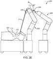
- FIG. 1illustrate a robotic surgical system in accordance with an embodiment of the present invention
- FIGS. 2A, 2B, 2Cillustrate a dual arm robotic surgical system in accordance with an embodiment of the present invention
- FIGS. 2D, 2Eillustrate alternate embodiments of a robotic surgical system of the present invention
- FIGS. 3A, 3Billustrate alternate configurations of multiple robotic arms and multiple virtual rails, in accordance with embodiments of the present invention
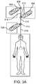
- FIGS. 4A, 4Billustrate modularity of an embodiments of the present invention
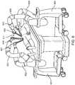
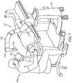
- FIGS. 5 and 6illustrate alternative embodiments of modules for the robotic surgical system of the present invention
- FIGS. 7 and 8illustrate alternative embodiments of modules for the robotic surgical system of the present invention
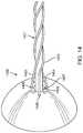
- FIGS. 9A, 9B, 9Cillustrate the structure of a sheath of a flexible endoscopic device, in accordance with an embodiment of the present invention
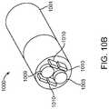
- FIGS. 10A, 10Billustrate the structure of a flexible endoscopic device in accordance with an embodiment of the present invention
- FIGS. 11A-11Killustrate muscling and curve alignment phenomena that manifest in previous flexible instruments and the improvement shown by an embodiment of the present invention
- FIG. 12illustrates the structure of flexible endoscopic device with an axially stiff tube within a lumen, in accordance with an embodiment of the present invention
- FIG. 13illustrates the structure of a helical pattern within a lumen of a flexible endoscopic device, in accordance with an embodiment of the present invention
- FIG. 14illustrates a specialized nose cone for manufacturing flexible endoscopic devices, in accordance with an embodiment of the present invention
- FIG. 15illustrates a system for manufacturing a flexible endoscopic device, in accordance with an embodiment of the present invention
- FIG. 16illustrates a cross-sectional view of a flexible endoscopic device where the pull lumens are arranged symmetrically around the circumference of the device, in accordance with an embodiment of the present invention
- FIG. 17Aillustrates a cross-sectional view of a flexible endoscopic device where the pull lumens are not arranged symmetrically around the circumference of the device, in accordance with an embodiment of the present invention
- FIG. 17Billustrates an isometric view of the flexible endoscopic device in FIG. 17A , in accordance with an embodiment of the present invention
- FIG. 18illustrates a flow diagram for a method for manufacturing the flexible endoscopic device in FIG. 17A-17B , in accordance with an embodiment of the present invention
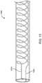
- FIG. 19illustrates an isometric view of a flexible endoscopic device with a nitinol hypotube backbone and a helixed payload lumen, in accordance with an embodiment of the present invention
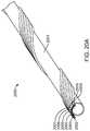
- FIG. 20Aillustrates an isometric view of a flexible endoscopic device with a hypotube backbone and non-uniformly spaced helixed lumens, in accordance with an embodiment of the present invention
- FIG. 20Billustrates a cross-sectional view of the distal end of endoscopic device 2000 from FIG. 20A ;
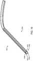
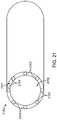
- FIG. 21illustrates an endoscopic device with helixed lumens that was created using extrusion-based manufacturing techniques, in accordance with an embodiment of the present invention.
- FIG. 22illustrates a flow chart for a method of manufacturing an endoscopic device with spiraled lumens, such as endoscopic device 2100 , using direct extrusion-based manufacturing techniques, in accordance with an embodiment of the present invention.
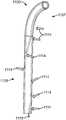
- Cart 2has wheels 4 provided for mobility, and has various utilities (e.g., pneumatic pressure 6 , power 8 , and central processing unit 10 ) for use by surgical system 100 during a procedure.
- Robotic arm 12is mounted on cart 2 , and has at least 3 degrees of freedom (“DOF”), and preferably 6 or more DOF.
- DOFdegrees of freedom
- Robotic arm 12is shown with only two arms/links 14 connected at joints 16 , but it is preferred to have multiple arms/links 14 , where each is connected at one or more joints to provide desired degrees of freedom at each joint.
- Module changer 18is provided at the distal portion of the robotic arm, which is used to exchange instrument modules based on a desired procedure, as more thoroughly described below.
- Module 20in one embodiment, connects to module changer and comprises instrument coupling 22 and instrument 24 .
- This robothas 7 DOF.
- the preferred robotic arm for the present inventionhas 7 joints, with the redundant joint provided to avoid potential arm collision with a patient, other robot arms, operating table, medical personal or equipment proximate to the operative field, while maintaining the wrist at the same pose so as not to interrupt an ongoing procedure.
- a robotic arm with at least 3 DOF, and more preferably 6 or more DOFwill fall within the inventive concepts described herein, and further appreciate that more than one arm may be provided with additional modules, where each arm may be commonly or separately mounted on one or more carts.
- Robotic surgical system 100may be configured in a manner to provide a plurality of surgical system configurations, for example by changing modules 20 (in robotics parlance module 20 is also known as an end effector).
- the systemmay comprise one or more mobile robotic platforms, which are staged at different locations in the operative room, or at a convenient nearby location. Each platform may provide some or all of power, pneumatic pressure, illumination sources, data communication cables and control electronics for a robotic arm that is coupled to the platform, and the module may draw from these utilities as well.
- System 100may alternatively have multiple robotic arms 12 mounted on one or more mobile carts 2 , or the arms may be mounted to the floor in order to provide a plurality of surgical configurations.
- Cart(s) 20may be located in various locations in the operating room in order to accommodate space needs and facilitate appropriate placement and motion of modules and instruments with respect to a patient. This capability enables the arms to be positioned in locations where they do not interfere with the patient, doctor, anesthesiologist or any supportive surgical equipment required for the selected procedure. During procedures, the robotic arms with instruments will work collaboratively via user control through separate control devices, which may include (not by way of limitation) a master console with haptic devices, joystick, or customized pedants.
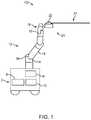
- FIG. 2Ashows robotic surgery system 200 in accordance with an embodiment of the present invention.
- System 200has first and second robotic arms 202 and 204 holding modules 206 and 208 , respectively.
- Module 206has controllable sheath 210 operatively connected thereto.
- Module 208has flexible endoscope 212 operatively connected thereto.
- FIG. 2Bshows an overhead view of system 200 where anesthesia cart 201 is provided towards the head of the patient. Additionally, control console 203 with a user interface is provided to control sheath 210 , flexible endoscope 212 , and the associate robotic arms 202 and 204 and modules 206 and 208 .
- Robotic arms 202 and 204align modules 206 and 208 such that proximal end 216 of sheath 210 is distal of the proximal end 222 of flexible endoscope 212 , and such that endoscope 212 remains axially aligned with sheath 210 at an approximate angle of 180 degrees between the two robotic arms, resulting in a “virtual rail” where the rail is approximately straight, or at 180 degrees. As will be described later, the virtual rail may have angles between 90-180 degrees.
- sheath 210is robotically inserted through, for example, a tracheal tube (not shown) in the mouth of and into patient 211 , and ultimately into the patient's bronchial system, while continually maintaining the virtual rail during insertion and navigation.
- Robotic armsmove sheath 210 and endoscope 212 axially relative to each other and in to or out of patient 211 under the control of a doctor (not shown) at a control console 203 .
- Navigationis achieved, for example, by advancing sheath 210 along with endoscope 212 into the patient, then endoscope 212 may be advanced beyond distal end 213 of the sheath, and the sheath may then be brought even with the endoscope, until a desired destination is reached.
- Other modes of navigationmay be used, such as and not by way of limitation using a guide wire through the working channel of the endoscope.
- the physicianmay be using any number of visual guidance modalities or combination thereof to aid navigation and performing the medical procedure, e.g., fluoroscopy, video, CT, MR etc.
- Distal end 220 of flexible endoscope 212is then navigated to an operative site and tools are deployed through tool channel 219 to perform desired procedures.
- the virtual railis maintained during the navigation procedure and any subsequent operative procedures. Any number of alternative procedures that may require a tool or no tool at all can be performed using the flexible endoscope sliding through the sheath, as the skilled artisan will appreciate.
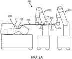
- FIG. 2Cshows an isometric view of system 200 in FIG. 2A .
- Modules 206 and 208 with associated sheath 210 and endoscope 212are attached to robotic arms 202 and 204 and arranged in a 180 degree virtual rail.
- the robotic armsare shown on a single cart, which provides added compactness and mobility. It will be appreciated that modules 206 and 208 have pulley systems or other actuation systems to tension tendons 228 (not shown) in sheath 210 and endoscope 212 to steer their respective distal ends.
- Modules 206 and 208 , particularly 208provide other desired utilities for the sheath and endoscope, such as pneumatic pressure, electrical, data communication (e.g., for vision), mechanical actuation (e.g., motor driven axels) and the like. These utilities may be provided to the modules through the robotic arms, from a separate source or a combination of both.
- FIGS. 2D and 2Eprovide alternative arrangements of robotic arms 202 and 204 showing the versatility of the robotic surgical system in accordance with embodiments of the present invention.
- robotic arms 202 and 204are extended to have the instrument enter the patient's mouth at 75 degrees from horizontal, while still maintaining a 180 degree virtual rail. This may be done during the procedure if circumstances require such, and/or may be done to accommodate space requirements within the room.
- the 75 degree anglewas chosen for demonstrative purposes, not by way of limitation.
- FIG. 2Eshows an alternative arrangement where the virtual rail is at 90 degrees and the instrument enters the patient's mouth at 75 degrees from horizontal.
- the robotic armscan manipulate the mechanism in a controlled fashion to create virtual rails.
- Such railsare useful in driving both rigid instrument and flexible instruments, and especially instruments which are telescoping or have other interaction requirements.
- the virtual railis not limited to a single rail but can consist of multiple virtual rails where the robotic arms act in concert to maintain the individual virtual rails in performance of one or more procedures.
- FIG. 3Ashows an overhead view of a system with multiple virtual rails, in an accordance with an embodiment of the present invention.
- robot arms 302 , 304 and 306respectively hold modules 308 , 310 , and 312 .
- Modules 308 and 310are each operatively coupled to flexible instrument 314 and instrument 316 .
- instrument 314may be a flexible endoscope and instrument 316 may be a telerobotically controlled instrument, which is a matter of choice for the purpose of explanation and not by way of limitation.
- Module 318is operatively coupled to a dual lumen sheath 318 , where each lumen receives instruments 314 and 316 .
- Robotic arms 302 and 304each maintain a virtual rail with robotic arm 316 , and movements of all three robotic arms are coordinated to maintain the virtual rails and to move instruments 314 , 316 and sheath 312 relative to each other and the patient.
- FIG. 3Bis an embodiment with a fourth robotic arm 320 with associated module 322 and instrument 324 .
- sheath 318 ′would have three lumens or alternatively sheath 318 ′ may be more than one sheath to provide access to instruments 314 , 316 , and 324 .
- the ability to increase or reduce the number of robotic arms with associated modules and instrumentspermits a great number and flexibility of surgical configurations, which, in turn, permits repurposing of expensive robotic arms and use a multiple relatively inexpensive modules thereby achieving great versatility at reduced expense for the advantage of robotically controlled surgical procedures.
- a plurality of arms and/or platformsmay be utilized. Each platform/arm must be registered to the others, which can be achieved by a plurality of modalities including, vision, laser, mechanical, magnetic, or rigid attachment.
- registrationmay be achieved by a multi-armed device with a single base using mechanical registration.
- mechanical registrationan embodiment may register arm/platform placement, position, and orientation based on their position, orientation and placement relative to the single base.
- registrationmay be achieved by a system with multiple base using individual base registration and “hand-shaking” between multiple robot arms.
- registrationcan be achieved by touching together arms from different bases, and calculating locations, orientation and placement based on that contact and the relative locations of those bases.
- registration targetsmay be used to match the position and orientations of the arms relative to each other. Through such registration, the arms and instrument driving mechanisms may be calculated in space relative to each other. The skilled artisan will be able to use many different methods to register the robotic platforms.
- certain embodiments of the present inventionare designed to readily exchange between multiple modules or end effector mechanisms.
- Various surgical procedures or steps within a proceduremay require the use of different modules and the associated instrument sets, for example, exchanging between different sized sheath and endoscope combinations.
- the interchangeabilityallows the system to reconfigure for different clinical procedures or adjustments to surgical approaches.
- FIG. 4Aillustrates an embodiment compatible with interchangeable modules and instruments.
- Surgical system 400like those shown and described previously, has one or more robotic arms 401 to which module 402 with instrument 403 is attached.
- Each moduleis a dedicated electromechanical system which is used to drive various types of instruments for specified procedures. They may contain sensors (e.g., RFID) or memory chips that record their calibration and application related information. A system calibration check may be required after a new mechanism is connected to the robot arm.
- a modulemay control an associated sheath or flexible endoscope.
- FIG. 4Bshows two different perspectives on exchange mechanisms 404 and 405 that may be used to exchange and attach modules 402 to robotic arm 401 .
- Exchange mechanisms 404 and 405provide the connection between a module, such as module 402 in FIG. 4A , and a robotic arm, such as robotic arm 401 in FIG. 4A .
- the mechanism 404may be the interface on a module, such as an instrument driving mechanism, for connection to mechanism 405 , which may be the interface on a robotic arm.
- Mechanism 404may provide a mechanism interface 411 for connecting flange 407 into ring 408 of mechanism 405 .
- the interfacemay provide for transmitting power ( 409 ), fiber optics, data connections, pneumatic connections ( 410 , 411 ), motors to drive pulley systems to control a tool, such as a sheath and flexible endoscope.
- a toolsuch as a sheath and flexible endoscope.
- the sheath and flexible endoscopewould be operatively coupled to the exchange mechanism.
- FIGS. 5-8illustrate additional, interchangeable modules that may be operated using system 400 from FIG. 4 .
- FIG. 5illustrates an embodiment of the present invention that uses a single port laparoscopic instrument 501 connected through an instrument interface 502 on a single robotic arm 503 that is directed at the abdomen 504 of a patient 505 .
- FIG. 6illustrates an embodiment of the present invention with two sets of robotic subsystems 601 and 604 , each with a pair of robotic arms 602 , 603 and 605 , 606 respectively. Connected through instrument interfaces at the distal end of each robotic arm are laparoscopic instruments 607 , 608 , 609 , 610 for procedures in an individual patient 611 .
- FIG. 7illustrates an embodiment of the present invention with a subsystem 701 with a single robotic arm 702 , where a microscope tool 704 connected to the robotic arm 702 through an instrument interface 703 .
- the microscopic tool 704may be used in conjunction with a second microscope tool 705 used by a physician 706 to aid in visualizing the operational area of a patient 707 .
- FIG. 8illustrates an embodiment of the present invention where subsystem 701 from FIG. 7 may be used in conjunction with subsystem 708 to perform microsurgery.
- Subsystem 708provides robotic arms 709 and 710 , each with microsurgical tools 711 and 712 connected through instrument interfaces on each respective arm.
- the one or more robotic armscan pick up and exchange tools at a table or other suitable holding mechanism within reach of the robotic arm.
- FIG. 4Ashows the interchangeable modules are stored on the side of the cart on which the robotic arm is mounted.
- FIGS. 9 and 10provide details of a sheath 210 and flexible endoscope 212 in accordance with an embodiment of the present invention.
- FIG. 9Ashows sheath 900 with distal end 901 and proximal end 902 and lumen 903 running between the two ends. Lumen 903 is preferably sized to slidingly receive a flexible endoscope (such as endoscope 1000 from FIG. 10 ).
- Sheath 900has walls 904 with tendons 905 and 906 running inside the length of walls 904 of sheath 900 . Tendons 905 and 906 slidingly pass through conduits 907 and 908 in walls 904 and terminate at distal end 901 .
- the tendonsmay be formed from steel.
- tensioning of tendon 905compresses distal end 901 towards conduit 907 , while minimizing bending of the helixed section 910 .
- appropriate tensioning of tendon 906compresses distal end 901 towards conduit 908 .
- lumen 903may not be concentric with sheath 900 .
- Tendons 905 and 906 and associated conduits 907 and 908 from sheath 900 from FIG. 9Apreferably do not run straight down the length of sheath 900 , but helix along a helixed section 910 and then run longitudinally straight (i.e., approximately parallel to the neutral axis) along distal section 909 . It will be appreciated that helixed section 910 may begin from the proximal end of distal section 909 extending proximally down sheath 910 and may terminate at any desired length for any desired or variable pitch.
- the length and pitch of helixed section 910is determined based on the desired properties of sheath 900 , taking into account desired flexibility of the shaft, and increased friction in the helixed section 910 .
- Tendons 905 and 906run approximately parallel to central axis 911 of sheath 900 when not in the helixed section, such as the proximal section of the endoscope 900 .
- the tendon conduitsmay be at ninety degrees to each other (e.g., 3-, 6-, 9- and 12-o'clock).
- the tendonsmay be spaced one hundred and twenty degrees from each other, e.g., three total tendons.
- the tendonsmay be not be equally spaced.
- theymay be all to one side of the central lumen.
- the tendon countmay differ from three or four.
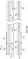
- FIG. 9Bshows a three-dimensional illustration of an embodiment of sheath 900 with only one tendon for the purpose of clarifying the distinction between non-helixed section 909 and a variable pitch helixed section 910 . While one tendon may be used, it is preferred to use multiple tendons.
- FIG. 9Cshows a three-dimensional illustration of an embodiment of sheath 900 with four tendons extending along distal section 909 , helixed section 910 and then proximal to helixed section 910 .
- FIG. 10Ashows a flexible endoscope 1000 with distal end 1001 and proximal end 1002 , that may be sized to slidingly reside within the sheath 900 from FIG. 9 .
- Endoscope 1000may include at least one working channel 1003 passing through it.
- Proximal end 902 of sheath 900 and proximal end 1002 of flexible endoscope 1000are, respectively, operatively connected to modules 206 and 208 from FIG. 2 respectively.
- Tendons 1004 and 1005slidingly pass through conduits 1006 and 1007 respectively in walls 1008 and terminate at distal end 1001 .
- FIG. 10Bshows the distal end 1001 of flexible endoscope 1000 , an exemplary embodiment, that has imaging 1009 (e.g., CCD or CMOS camera, terminal end of imaging fiber bundle etc.), light sources 1010 (e.g., LED, optic fiber etc.) and may include at least one working channel opening 1003 .
- Other channels or operating electronics 1006may be provided along flexible endoscope 1000 to provide various known capabilities at the distal end, such as wiring to camera, insufflation, suction, electricity, fiber optics, ultrasound transducer, EM sensing, and OCT sensing.
- the distal end 1001 of endoscope 1000may include a “pocket” for insertion of a tool, such as those disclosed above.
- the pocketmay include an interface for control over the tool.
- a cablesuch as an electrical or optical cable, may be present in the endoscope in order communicate with the interface.
- sheath 900 from FIG. 9A and flexible endoscope 1000 from FIG. 10Aboth, preferably, may have robotically controlled steerable distal ends.
- the structure of sheath 900 and flexible endoscope 1000 enabling this controlis thus substantially the same for both, and thus discussion for the construction of sheath 900 will be limited to that of the sheath 900 with the understanding that the same principles apply to the structure of the flexible endoscope 1000 .
- tendons 1004 and 1005 and associated conduits 1006 and 1007 from the endoscope 1000 from FIG. 10Ado not run longitudinally straight (i.e., approximately parallel to the neutral axis) down the length of endoscope 1000 , but helix along different portions of endoscope 1000 .
- the helixed sections of endoscope 1000may be determined based on the desired properties of the endoscope, taking into account desired flexibility of the shaft, and increased friction in the helixed section.
- Tendons 1004 and 1005run approximately parallel to central axis of endoscope 1000 when not in the helixed section.
- the helixed sectionis to help isolate the bending to the distal section, while minimizing bending that occurs along the shaft proximal to the distal section.
- the helix pitch of the conduits in sheath 900 and endoscope 1000may be varied along the length of the helixed section, which, as more fully described below will alter the stiffness/rigidity of the shaft.
- sheath 900 and endoscope 1000present significant advantages over previous flexible instruments without helixed conduits, particularly when navigating non-linear pathways in anatomical structures.
- sheath 900 and endoscope 1000When navigating curved pathways, it is preferable for sheath 900 and endoscope 1000 to remain flexible over most of the lengths thereof, and to have a controllably steerable distal end section, while also minimal secondary bending of the instrument proximal to the distal bending section.
- tensioning the tendons in order to articulate the distal endresulted in unwanted bending and torquing along the entire length of the flexible instrument, which may be referred to as “muscling” and “curve alignment” respectively.
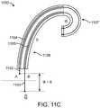
- FIGS. 11A to 11Cillustrates how the prior flexible instruments exhibit undesirable “muscling” phenomenon when tendons are pulled.
- a previous flexible instrument 1100may have four tendons or control wires along the length of the instrument 1100 that run approximately parallel to the neutral axis 1101 . Only tendons 1102 and 1103 are shown in cross section traveling through conduits 1104 and 1105 (also known as control lumens) in the shaft wall, each of which are fixed connected to a control ring 1106 on the distal end of the instrument 1100 .
- Instrument 1100is intentionally designed to have a bending section 1107 and shaft 1107 .
- the shaft 1108may incorporate stiffer materials, such as stiffeners.
- FIG. 11Billustrates an idealized articulation of the bending section 1107 .
- articulation of only the distal bending section 1107results an amount represented by ⁇ , where the length difference at the proximal ends of tendons 1102 and 1103 would be a f( ⁇ ).
- the shaft 1108remains straight along the neutral axis 1101 . This is achieved by having a proximal region 1108 of a significantly higher stiffness than the distal region of 1107 .
- FIG. 11Cillustrates the real world result from tensioning tendon 1103 .
- pulling tendon 1103results in compressive forces along the entire length of the shaft as the tension is non-localized.
- the entire compressive loadwould transmit equally down the central axis and most or all bending would occur at the bending section 1107 .
- the axial loadis transferred off the neutral axis 1101 in the same radial orientation of the neutral axis which creates a cumulative moment along the neutral axis.
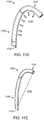
- FIG. 11Dillustrates the forces that contribute to muscling in three-dimensions.
- tensioning tendon 1103 along instrument 1100causes the tendon 1103 to directionally exert forces 1112 towards one side of the instrument.
- the direction of forces 1112reflect that the tension in tendon 1103 causes the tendon to seek to follow a straight line from the tip of the distal bending section 1107 to the base of the shaft 1108 , i.e., the lowest energy state as represented by the dotted line 1113 in FIG. 11E .
- the shaft 1108is rigid (i.e., not susceptible to bending under the applicable forces)
- only the distal bending section 1107will bend.
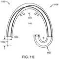
- FIGS. 11F to 11Jillustrate how previous flexible instruments suffer from curve alignment phenomenon during use in non-linear pathways.
- FIG. 11Fshows a previous flexible instrument 1100 at rest within a non-linear path, represented by having a bend ⁇ along the shaft 1108 of instrument 1100 . For example, this may result from the instrument navigating past a bend in the bronchial lumens. Due to the non-linear bend, tendons 1102 and 1103 in instrument 1100 need to lengthen or shorten at the proximal end by a length to accommodate the non-linear bend, which length is represented by F( ⁇ ).
- Extension and compressive forcesexist on the lumens/conduits at the top and bottom of the bend, as depicted by arrows 1109 (extension forces) and 1110 (compressive forces) respectively. These forces exist because the distance along the top of the bend is longer than the neutral axis, and the distance along the inside of the bend is shorter than the neutral axis.
- FIG. 11Gillustrates the mechanics of articulating the distal bending section 1107 of the instrument 1100 in the same direction as bend ⁇ , where one would pull tendon 1103 .
- the additional compressive force along the non-linear conduitis highly undesirable because: (i) it forces the flexible instrument against the anatomy causing potential injury; (ii) potential for injury distracts the operator because he/she has to constantly monitor what the shaft is doing, when he/she should be able to “assume” the anatomy is governing the profile of the instrument shaft; (iii) it is an inefficient way to bend the instrument, (iv) it is desired to isolate bending at the distal section to aid in predictability and controllability (i.e., ideal instrument will have bending section that bends as commanded and is not a function of the anatomical non-linear path), and (v) it forces a user to pull on a tendon 1103 an unpredictable additional length ( ⁇ + ⁇ + ⁇ ).
- FIG. 11Hillustrates a scenario where one desires to articulate the distal end opposite to bend ⁇ , requiring pulling tendon 1102 .
- Pulling tendon 1102applies a compressive load 1111 along the top of the curve, which is in contrast to the extension loads for the bend in its resting state as shown in FIG. 11D .
- Tendons 1102will attempt to return to its lowest energy state, i.e., where the compressive load 1111 rests on the inside of the bend ⁇ , and cause the shaft 1108 to rotate in the direction of the arrow 1112 so that the tendon 1102 rests on the inside of the bend ⁇ .
- FIG. 11Hillustrates a scenario where one desires to articulate the distal end opposite to bend ⁇ , requiring pulling tendon 1102 .
- FIGS. 9 and 10substantially resolves the muscling and curve alignment phenomena through the provision of helixed section 910 .
- helixing the control lumens around instrument 1100such as in helixed section 910 from FIGS. 9B and 9C , radially distributes compressive loads 1114 from a single tendon 1115 around instrument 1100 .
- a tensioned tendon 1115symmetrically transmits the compressive load 1114 in multiple directions around the neutral axis
- the bending moments imposed on the shaftare also symmetrically distributed around the longitudinal axis of the shaft, which counterbalance and offset opposing compressive and tensile forces.
- the distribution of the bending momentsresults in minimal net bending and rotational forces, creating a lowest energy state that is longitudinally parallel to the neutral axis, as represented by the dotted line 1116 . This eliminates or substantially reduces the muscling and curve alignment phenomena.
- the pitch of helixingcan be varied to affect friction and the stiffness of the helixed section.
- the helixed section 910may be shorter to allow for a larger non-helixed section 909 , resulting in a larger articulating section and possibly less friction.
- Helical control lumenscreate several trade-offs. Helical control lumens still do not prevent buckling from tension in the tendons. Additionally, while muscling is greatly reduced, “spiraling”—the curving of the shaft into a spiral, spring-like pattern due to tension in the tendons—is very common. Moreover, helical control lumens requires compensation for additional frictional forces as the tendon travels through the lumen for longer distances.
- FIG. 12illustrates the structure of a flexible endoscopic device with an axially stiff tube within a lumen, in accordance with an embodiment of the present invention.
- a section of an endoscopic devicehas a single lumen 1201 with a pull wire 1202 wrapped in a helical pattern around the shaft 1200 .
- an axially stiff tube 1203“floats” around the pull wire 1202 and within the lumen 1201 .
- the floating tube 1203anchored at the beginning and end of the helical portion of the shaft 1200 , the floating tube 1203 extends and compresses in response to tension in pull wire 1202 and external tortuosity, relieving the walls of lumen 1201 from the extension and compression forces.
- the tube 1203may be anchored by pull rings at the beginning and end of the lumen.
- tube 1203may be anchored using solder, welding, gluing, bonding, or fusing methods to the beginning and end of the lumen.
- geometric engagementsuch as flared geometries, may be used to anchor tube 1203 .
- the tube 1203may be formed from hypodermic tubes, coil pipes, Bowden cables, torque tubes, stainless steel tubes, or nitinol tubes.
- the embodiment in FIG. 12may be constructed by fixedly attaching the tubes to a distal end piece and proximal end piece and collectively twisting the tubes by rotating either or both end pieces.
- the rotation of the end piece(s)ensures that the tubes are helixed in the same pitch, manner, and orientation.
- the end piecesmay be fixedly attached to the lumen to prevent further rotation and restrict changes to the pitch of the helixing.
- FIG. 13illustrates the structure of a helical pattern within a lumen of a flexible endoscopic device, in accordance with an embodiment of the present invention.
- lumen 1300contains structures 1301 and 1302 that form a helical or spiraled pattern along its walls.
- the structuresare formed from materials that are axially stiff and tube-like in shape.
- the structuresmay be formed from hypodermic tubes (“hypo tube”), coil pipes, or torque tubes.
- hypo tubehypodermic tubes
- the structuresmay have different starting points along the walls of lumen 1300 .
- the materials, composition, and characteristics of structures 1301 and 1302may also be selected and configured for desired stiffness and length.
- the pitch of the helical pattern formed by structures 1301 and 1302may also be configured for a desired stiffness and flexibility of lumen 1300 .
- lumen 1300may be the main central lumen of a flexible endoscope, such as endoscope 1000 from FIG. 10 .
- the sheath and endoscope devicesare constructed using steerable catheter construction methodologies.
- steerable cathetershave been manufactured by braiding wires or fibers, i.e., braid wire, around a process mandrel in a braiding machine, i.e., braider.
- a process mandrelwould be typically inserted into a feed tube of a braider that was coupled to a braid cone support tube and braid cone holder.
- the process mandrelwould be advanced through the feed tube. As the process mandrel progressed, it would eventually emerge through a center hole in a nose cone.
- the nose coneprovided a round, smooth shape on which the braid wire from the surrounding horn gears may easily slide around the mandrel during the braiding process.
- the nose conewas typically held in a position that was fixed axially and radially relative to the braid cone holder using a set screw keyed to the braid cone holder. As the process mandrel was pulled through the nose cone, the horn gears translate and rotate around the mandrel to braid the braid wire around the mandrel in a pre-determined pattern and density.
- supplemental mandrelsare passed through the center of the horn gears for braiding onto the main process mandrel.
- the supplemental mandrelssometimes constructed from Teflon-coated polyimide, may be braided onto the main process mandrel as it is pulled through the nose cone.
- the supplemental mandrelsmay be passed through small holes in the nose cone that surround the center hole. As the main process mandrel is pulled through the nose cone, the smaller, supplemental mandrels may be braided to the main process mandrel as they are pulled from the nose cone.
- a second layer of braid wireis typically laid onto the main process mandrel after applying the supplemental mandrels.
- a polymer coating or jacketmay be sheathed, heated, and bonded to the braiding composite.
- the mandrelsare typically removed from the braided composite to create a central lumen (main process mandrel) for camera and light tools, and several control lumens (supplemental mandrels) for steering control.
- This method of manufactureresults in endoscopes with control lumens that are longitudinally parallel to the neutral axis.
- catheter-like endoscopes with tension on tendons in longitudinally parallel lumensexhibit muscling and curve alignment phenomena.
- FIG. 14illustrates a specialized nose cone for manufacturing helical lumens in a flexible sheath and/or endoscope, in accordance with an embodiment of the present invention.
- Rotating the nose cone 1400 at the same time that the main process mandrel 1401 is pulled through the nose cone 1400allows for supplemental mandrels 1402 , 1403 , and 1404 to be applied in a helical pattern around the mandrel 1401 through supplemental holes 1405 , 1406 , and 1407 respectively that surround the center hole 1408 , similar to how the horn gears braid the braid wire around the main process mandrel 1401 .
- FIG. 15illustrates a system for manufacturing a flexible sheath and endoscope in accordance with an embodiment of the present invention.
- the nose cone 1501may be fixedly coupled to a rotating feed tube 1502 using a set screw that holds the nose cone 1501 in a fixed position relative to the feed tube 1502 .
- the center hole 1503 of the nose cone 1501may be aligned with the rotating feed tube 1502 in order to smoothly pull the main process mandrel 1304 through both structures.
- traditional systemsused a set screw to fixed couple the nose cone 1501 to the braid cone support holder 1505 .
- the rotating feed tube 1502has an outside diameter less than the interior diameter of the braid cone support tube 1506 , also known as a mandrel guide tube, and an interior diameter larger than the circumferential space of the center hole 1503 of the nose cone 1501 .
- the rotating feed tube 1502may generally be large enough for the main process mandrel 1504 and the supplemental mandrels to be passed through to the nose cone 1501 .
- the rotating feed tube 1502is long enough to pass through the center of the horn gears of the braider.
- the rotating feed tube 1502is attached to a mechanism that may hold bobbins of material for the supplemental mandrels that will be passed through the feed tube 1502 to supplemental holes around the nose cone 1501 .
- the feed tube 1502may be attached to a drive mechanism that controls the rate of rotation of the feed tube 1502 and thus the rotation of the nose cone 1501 .
- the drive mechanismmay be a rotating gear 1507 .
- the drive mechanismis either geared to the braider itself or independently controlled to vary or hold constant the rate of rotation of the rotating feed tube 1502 and thus the rate of rotation of the nose cone 1501 .
- the rate of rotation and the rate of braidingwill govern the pitch of the supplemental mandrels on the main process mandrel 1504 . As discussed earlier, this may affect the flexibility, stiffness, and “pushability” of the device.
- varying the circumferential orientation of the pull lumensmay change the stiffness of the helixed section of the endoscope. In manufacture, this is achieved by altering the pitch of the supplemental, spiraling mandrels. As the pitch (i.e., the angle off the longitudinal axis) of the mandrels decreases, the bending stiffness of the braided composite increases. Conversely, as the pitch of the supplemental mandrels increases, the bending stiffness decreases. As shown in FIG. 9B , in some embodiments, the pitch of the supplemental mandrels may be varied within the helixed portion ( 910 ). In those embodiments, the bending stiffness of the braided composite may vary even within the helixed portion.
- the braiding machinemay be stopped to make alterations to the braided composite.
- one alterationmay be the addition of straight wires or reinforcement rods.
- Reinforcement rodsmay significantly increase the buckling, axial and bending stiffness of a braided laminated composite. Reinforcement rods may be particularly helpful for longer endoscopes which may require specialized anti-buckling construction or manual assistance to reduce the buckling of the device so that it may be inserted into a patient.
- the braiding machinemay be configured to selectively braid reinforcement rods that may be pulled from holes in the nose cone onto the process mandrel, where the reinforcement rods are captured and held in place by the braid wire.
- the absence of reinforcement rods in the distal region of the resulting endoscopepreserves the device's flexibility in the distal end while increasing the stiffness in the proximal region. This combination of properties makes the resulting endoscope easier for a physician to guide, insert, and push the device into an endolumenal cavity of a patient.
- the supplemental mandrelIn zero degree construction, the supplemental mandrel is necessarily confined in an “over-under manner” by the braid, resulting in all clockwise braided braid wire being woven “over” the supplemental mandrels, while all counter-clockwise braided braid wire is woven “under” the supplemental mandrels. As zero degree construction locks the supplemental mandrels in place radially, it is undesirable where varying the pitch of the supplemental mandrel along the main process mandrel is required.
- horn gearsas a pass-through for the supplemental mandrels limits the number of supplemental mandrels that may be applied to the main process mandrel. For example, a sixteen carrier braider can apply up to eight mandrels, a twenty-four carrier braider can only have up to twelve mandrels. In contrast, use of holes in the nose cone allows any number of mandrels to be passed through to the main process mandrel.
- the supplemental mandrelsmay be applied to the main process mandrel without the benefit of a second, outer layer of braid wire. Instead, the supplemental mandrels may be applied without braid wire.
- the bonded/fused polymer jacketmay hold the mandrels, and thus lumens in place.
- the mandrelsmay be held in place using a casting around the braided composite. Since the outer braid layer is absent from the manufacturing endoscopic device, the diameter and circumference of the device cross-section is reduced.
- the supplemental mandrelsmay be held in place by sleeving a polymer jacket over the process mandrel.
- the castingis the same material as the exterior material for the endoscopic device.
- the supplemental mandrelsmay be braided onto the main process mandrel much like the braid wire.
- the supplemental mandrelsmay be braided using the even numbered horn gears, while held in place by braid wire braided using the odd numbered horn gears.
- the supplemental mandrels, and thus the lumensmay be woven into the walls of the central lumen.
- embodiments manufactured using this meansalso tend to have lower circumferential area.
- the helixed lumen structuresmay be manufactured using extruded molds. These molds may generate the helixed lumen structures to create a jacket from PTFE, pebax, polyurethane, and nylon.
- the extruded structuresmay be formed using a mold around a braided mandrel.
- FIG. 16illustrates a cross-sectional view of a flexible endoscopic device where the pull lumens are arranged symmetrically around the circumference of the device, in accordance with an embodiment of the present invention.
- device 1600has a central working channel 1601 and pull lumens ( 1602 , 1603 , 1604 , and 1605 ) spaced symmetrically around the working channel 1601 and within the outer jacket 1606 .
- the lumens and pull wiresmay not be distributed evenly or equidistant from each other around the circumference of the sheath and/or flexible endoscope.
- grouping all of the lumens and pull wires onto the same side or hemispheric region (e.g., top vs. bottom hemisphere) of the sheath and endoscopeallows for a smaller outer diameter. This may be desirable for certain applications and procedures.
- FIG. 17Aillustrates a cross-sectional view of a flexible endoscopic device where the pull lumens are not arranged symmetrically around the circumference of the device, in accordance with an embodiment of the present invention.
- device 1700Similar to device 1600 of FIG. 16 , device 1700 has a working channel 1701 , pull lumens 1702 , 1703 , 1704 , and 1705 , and an outer jacket 1706 .
- the working channelmay be created by a small hollow tube (“hypo tube”) created from a flexible metal alloy, such as nitinol.
- pull lumens 1702 , 1703 , 1704 , and 1705are grouped together to reduce the outside diameter of the device, as shown by the circumference of the outer jacket 1706 .
- the pull lumensare not equidistant from each other around the circumference of the working channel 1701 , helixing the pull lumens in the arrangement shown in device 1700 still exhibits the advantages of helixing, e.g., avoiding muscling or curve alignment phenomena.
- the pull lumens of device 1700are arranged adjacent to each other around working channel 1701 , other embodiments may be arranged in a different pattern, such as spaced out within same hemisphere or clustered together.
- the jacket 1706may be created from plastic or any other material that may be stretched, bonded or melted during the manufacture of device 1700 .
- FIG. 17Billustrates an isometric view of the flexible endoscopic device 1700 disclosed in FIG. 17A , in accordance with an embodiment of the present invention.
- pull lumens 1702 , 1703 , 1704 , and 1705helix around the working channel 1701 .
- the pitch of the helixed pull lumensmay be varied in order to obtain desired properties, such as stiffness and bending flexibility, from device 1700 .
- FIG. 18illustrates a flow diagram for a method for manufacturing device 1700 , in accordance with an embodiment of the present invention.
- the manufacturing process 1800begins with selecting a backbone for the workpiece.
- the backbonemay be a hollow tube, such as a hypodermic “hypo” tube formed from nitinol alloy.
- a hypotubemay be a small, micro or nano radius tube as small as 0.005′′ in outside diameter.
- tube materialsmay be preferred since tubular structures simultaneously exhibit axial stiffness and low bending stiffness.
- the tubeprovides for a working channel through which useful tools and cables may be inserted, such as optics, aspiration, irrigation, and controls.
- the backbonemay be a solid rod, such as for use as an articulable guidewire.
- process mandrelsmay be spiraled around the backbone at the desired pitch.
- the process mandrelsmay be coated with polytetrafluoroethylene (PTFE) for easy removal during step 1805 .
- PTFEpolytetrafluoroethylene
- the pitch of the spiraled mandrelsmay fixed or dynamic, allowing for the different bending and stiffness properties depending on the application. The lower the pitch, i.e., more longitudinally parallel to the neutral axis of the backbone, the lower the axial compression under tension, while also exhibiting increased muscling and curve alignment phenomena. Higher pitch spiraling generally exhibits reduced muscling and curve alignment phenomena at the cost of increased axial compression under tension.
- the resulting workpiececomprising of a backbone and at least one spiraled mandrel, may be sheathed or covered in a “jacket”.
- the jacketis a simple extruded tube or sheath. Selection of the means of the sheathing is critical; as sheathing may inadvertently alter the pitch of the process mandrels around the backbone.
- the “sheathing” processmay be accomplished by casting, deposition, overextrusion, or any other means that would be known in the art.
- the jacketmay be bonded to the workpiece. This may involve melting, molding or bonding to the workpiece using any number of processes known to one skilled in the art. Once bonded, the jacket will hold the process mandrels in place.
- step 1805once the bonding process is complete, the spiraled process mandrels may be removed to create helixed pull lumen cavities that run longitudinally along the length of the workpiece.
- step 1806following removal of the mandrels, the pull wires may be threaded into the remaining cavities. In operation, the pull wires may then be used to facilitate pull wires for articulating the endoscopic device.
- method 1800does not make use of braiding, it provides for the construction of workpieces and devices with relatively small outer diameters, which may be appropriate for reaching areas requiring small instruments, e.g., microsurgical applications. While the method of manufacture previously discussed may be applied to devices of varying sizes and outer diameters, the preferred embodiments generally have an outer diameter of less than 2 mm.
- Integration of the resulting workpiece into an endoscopic devicemay be accomplished by melting, molding, bonding, and casting the workpiece jacket to the outer jacket of other components, such as a flexure or tool tip.
- the backbonemay include structure for an adjoining microsurgical flexure tool, such as ribbing for an increased bend radius and longitudinally-aligned cavities for tools and control wires.
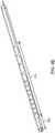
- FIG. 19illustrates an isometric view of a flexible endoscopic device with a hypotube backbone and helixed lumens, in accordance with an embodiment of the present invention.
- endoscopic device 1901may be constructed from a solid hypotube backbone 1902 , preferentially constructed from a semi-rigid material, such as nitinol alloy. Different embodiments have been shown to work with different alloys.
- various sizes of hypotubesmay be employed depending on the desired characteristics of the endoscopic device 1901 .
- the inner diameter of the hypotubesmay range in size from 0.015′′ to 0.050′′ with wall thickness ranging from 0.001′′ to 0.005′′.
- Lumens 1902 , 1903 , 1904 , 1905 , and 1906may be spiraled around the nitinol backbone. In some embodiments, a subset of lumens 1902 , 1903 , 1904 , 1905 , and 1906 may be sized to convey pull wires down the length of the endoscopic device 1901 . As discussed earlier, pull wires may be used to apply compressive force along the endoscopic device to induce articulation at a distal location.
- a subset of lumens 1902 , 1903 , 1904 , 1905 , and 1906may be used as payload lumens to convey laser fibers, mechanical tools, irrigation, aspiration, or other payloads that may be useful for diagnostic or therapeutic applications.
- Use of spiraled payload lumenspotentially frees up the central working channel for other (often larger) payloads.
- Payload lumens that are spiraled around the hypotube backbonealso balance the compressive and extension forces on a payload that results for navigation through tortuous pathways. In contrast, those forces may affect, degrade or damage the payload when the payload lumens run longitudinally straight along the backbone.
- the central working channelmay convey a concentrically aligned endoscopic device that may be used for extension or retraction.
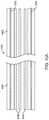
- FIG. 20Aillustrates an isometric view of a flexible endoscopic device with a hypotube backbone and non-uniformly spaced helixed lumens, in accordance with an embodiment of the present invention.
- Endoscopic device 2000may be similarly constructed around a hypotube backbone 2001 that may use a nitinol alloy.
- lumens 2002 , 2003 , 2004 , 2005 , 2006 , 2007 , 2008 , and 2009may arranged around the backbone 2001 without uniform spacing.
- lumens 2002 , 2003 , 2004 , 2005 , 2006 , 2007 , 2008 , and 2009may be arranged to reduce the outside diameter of device 2000 .
- these lumensmay be configured to convey a combination of pull wires, laser fibers, mechanical tools, irrigation, aspiration, or other payloads that may be useful for diagnostic or therapeutic applications at a distal location.
- FIG. 20Billustrates a cross-sectional view of the distal end of endoscopic device 2000 from FIG. 20A .
- the distal end of endoscopic device 2001provides access to a working channel 2011 , and access ports to lumens 2002 , 2003 , 2004 , 2005 , 2006 , 2007 , 2008 , and 2009 as shown by 2012 , 2013 , 2014 , 2015 , 2016 , 2017 , 2018 and 2019 .
- the access ports 2012 , 2014 , 2016 , and 2018may be inaccessible since they serve as lumens for pull wires.
- access ports 2012 , 2014 , 2016 , and 2018may be sealed due to anchoring of their related pull wires.
- the lumensmay be held in place using an exterior jacket 2020 .
- endoscopic devices 1901 and 2000may be constructed using the manufacturing process 1800 from FIG. 18 .
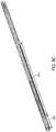
- FIG. 21illustrates an endoscopic device with helixed lumens that was created using extrusion-based manufacturing techniques, in accordance with an embodiment of the present invention.
- an endoscopic device 2100may be constructed by extruding a wall 2101 formed from thermoplastic material around a working channel 2102 .
- the endoscopic devicemay have multiple working channels.
- the wall 2101may be formed from a variety of thermoplastic material, including but not limited to pebax, nylon, or polyurethane.
- the wall thicknessmay be as thin as 0.010′′ or as thick as 0.030′′.
- the outer diameter of such a device 2100may range from 0.060′′ to 0.200′′.
- a series of lumens 2103may be built into the wall 2101 for purposes of conveying actuation tendons (such as pull wires), tools and means for irrigation, aspiration, illumination, and image capture.
- lumens 2103may also be spiraled or helixed along a certain portion of the length of the device where muscling and curve alignment phenomena are intended to be minimized.
- the extent and pitch of the spiral/helixmay be predetermined and designed with specific applications and properties in mind.
- FIG. 22illustrates a flow chart for a method of manufacturing an endoscopic device with spiraled lumens, such as endoscopic device 2100 , using direct extrusion-based manufacturing techniques, in accordance with an embodiment of the present invention.
- a manufacturermay first select the device and cross-sectional profile of the desired workpiece.
- the selected cross-sectional profilemay vary depending on the application and intended use of the resulting endoscope.
- a thicker wallmay be desirable to improved stiffness.
- a thinner wallmay be desirable to improve bendability.
- a thinner wallmay be desirable to reduce the outside diameter in order to fit in smaller anatomical lumens and hard-to-reach areas of the patient's anatomy.
- the manufacturermay also vary the size of the desired working channel and the size and number of lumens. Altering the size of the working channel allow a larger channel or increased wall thickness for more stiffness. In some embodiments, only a few lumens may be necessary for the intended application. In some embodiments, more than eight lumens may be desirable, often at the cost of stiffness. Having selected the desired cross-sectional profile, the cross-sectional profile may be used to create an extrusion die.
- the extrusionmay begin using the selected die shape from the cross-sectional profile in 2201 .
- the billet materialmay be a thermoplastic, such as pebax, nylon, or polyurethane.
- the extrusion lengthmay be determined based on the amount of the billet material pushed through the die.
- the spiral lumensmay be generated.
- the extrusionmay be rotated as it is being made, i.e., as the billet is pushed through the die, the extruded material may be rotated as it exits the die.
- the dieitself may be rotated relative to the billet in order to generate the desired spiraling. In either method, the rotation may be customized, allowing for a variety of helical and spiral pitches based on the desired properties of the endoscopic device. For example, a more aggressive pitch may require faster rotation of the die and/or extruded material. A gentler pitch may be created using a slower rotation.
- the spiralingmay be generated after the completion of the extrusion process.
- the extrusionmay be subsequently heated and twisted in order to generate the desired properties. In some circumstances, this may involve heating the extrusion to its glass-transition temperature in order to make the material pliable. After twisting the extrusion to obtain the desired pitch, the extrusion may be quickly cooled to lock the pitch of the spiraled lumens in place.
Landscapes
- Health & Medical Sciences (AREA)
- Life Sciences & Earth Sciences (AREA)
- Surgery (AREA)
- Engineering & Computer Science (AREA)
- Animal Behavior & Ethology (AREA)
- Biomedical Technology (AREA)
- Heart & Thoracic Surgery (AREA)
- General Health & Medical Sciences (AREA)
- Public Health (AREA)
- Veterinary Medicine (AREA)
- Biophysics (AREA)
- Medical Informatics (AREA)
- Molecular Biology (AREA)
- Nuclear Medicine, Radiotherapy & Molecular Imaging (AREA)
- Optics & Photonics (AREA)
- Physics & Mathematics (AREA)
- Pathology (AREA)
- Radiology & Medical Imaging (AREA)
- Hematology (AREA)
- Anesthesiology (AREA)
- Pulmonology (AREA)
- Robotics (AREA)
- Endoscopes (AREA)
Abstract
Description
Claims (14)
Priority Applications (3)
| Application Number | Priority Date | Filing Date | Title |
|---|---|---|---|
| US14/583,021US10792464B2 (en) | 2014-07-01 | 2014-12-24 | Tool and method for using surgical endoscope with spiral lumens |
| US17/015,514US11759605B2 (en) | 2014-07-01 | 2020-09-09 | Tool and method for using surgical endoscope with spiral lumens |
| US18/450,159US20240082539A1 (en) | 2014-07-01 | 2023-08-15 | Multiple-pull-wire robotic instrument articulation |
Applications Claiming Priority (3)
| Application Number | Priority Date | Filing Date | Title |
|---|---|---|---|
| US201462019816P | 2014-07-01 | 2014-07-01 | |
| US201462057936P | 2014-09-30 | 2014-09-30 | |
| US14/583,021US10792464B2 (en) | 2014-07-01 | 2014-12-24 | Tool and method for using surgical endoscope with spiral lumens |
Related Child Applications (1)
| Application Number | Title | Priority Date | Filing Date |
|---|---|---|---|
| US17/015,514DivisionUS11759605B2 (en) | 2014-07-01 | 2020-09-09 | Tool and method for using surgical endoscope with spiral lumens |
Publications (2)
| Publication Number | Publication Date |
|---|---|
| US20160001038A1 US20160001038A1 (en) | 2016-01-07 |
| US10792464B2true US10792464B2 (en) | 2020-10-06 |
Family
ID=55016276
Family Applications (3)
| Application Number | Title | Priority Date | Filing Date |
|---|---|---|---|
| US14/583,021Active2037-02-04US10792464B2 (en) | 2014-07-01 | 2014-12-24 | Tool and method for using surgical endoscope with spiral lumens |
| US17/015,514Active2036-02-15US11759605B2 (en) | 2014-07-01 | 2020-09-09 | Tool and method for using surgical endoscope with spiral lumens |
| US18/450,159PendingUS20240082539A1 (en) | 2014-07-01 | 2023-08-15 | Multiple-pull-wire robotic instrument articulation |
Family Applications After (2)
| Application Number | Title | Priority Date | Filing Date |
|---|---|---|---|
| US17/015,514Active2036-02-15US11759605B2 (en) | 2014-07-01 | 2020-09-09 | Tool and method for using surgical endoscope with spiral lumens |
| US18/450,159PendingUS20240082539A1 (en) | 2014-07-01 | 2023-08-15 | Multiple-pull-wire robotic instrument articulation |
Country Status (1)
| Country | Link |
|---|---|
| US (3) | US10792464B2 (en) |
Cited By (56)
| Publication number | Priority date | Publication date | Assignee | Title |
|---|---|---|---|---|
| US10959792B1 (en) | 2019-09-26 | 2021-03-30 | Auris Health, Inc. | Systems and methods for collision detection and avoidance |
| US11109928B2 (en) | 2019-06-28 | 2021-09-07 | Auris Health, Inc. | Medical instruments including wrists with hybrid redirect surfaces |
| US11147635B1 (en) | 2020-06-19 | 2021-10-19 | Remedy Robotics, Inc. | Systems and methods for guidance of intraluminal devices within the vasculature |
| US11147633B2 (en) | 2019-08-30 | 2021-10-19 | Auris Health, Inc. | Instrument image reliability systems and methods |
| US11207141B2 (en) | 2019-08-30 | 2021-12-28 | Auris Health, Inc. | Systems and methods for weight-based registration of location sensors |
| US11234780B2 (en) | 2019-09-10 | 2022-02-01 | Auris Health, Inc. | Systems and methods for kinematic optimization with shared robotic degrees-of-freedom |
| US11282251B2 (en) | 2018-05-02 | 2022-03-22 | Covidien Lp | System and method for constructing virtual radial ultrasound images from CT data and performing a surgical navigation procedure using virtual ultrasound images |
| US11357586B2 (en) | 2020-06-30 | 2022-06-14 | Auris Health, Inc. | Systems and methods for saturated robotic movement |
| US11369386B2 (en) | 2019-06-27 | 2022-06-28 | Auris Health, Inc. | Systems and methods for a medical clip applier |
| US11382650B2 (en) | 2015-10-30 | 2022-07-12 | Auris Health, Inc. | Object capture with a basket |
| US11439419B2 (en) | 2019-12-31 | 2022-09-13 | Auris Health, Inc. | Advanced basket drive mode |
| US11464591B2 (en) | 2015-11-30 | 2022-10-11 | Auris Health, Inc. | Robot-assisted driving systems and methods |
| US11511079B2 (en) | 2014-07-01 | 2022-11-29 | Auris Health, Inc. | Apparatuses and methods for monitoring tendons of steerable catheters |
| US11529190B2 (en) | 2017-01-30 | 2022-12-20 | Covidien Lp | Enhanced ablation and visualization techniques for percutaneous surgical procedures |
| US11534249B2 (en) | 2015-10-30 | 2022-12-27 | Auris Health, Inc. | Process for percutaneous operations |
| US11571229B2 (en) | 2015-10-30 | 2023-02-07 | Auris Health, Inc. | Basket apparatus |
| US11690683B2 (en) | 2021-07-01 | 2023-07-04 | Remedy Robotics, Inc | Vision-based position and orientation determination for endovascular tools |
| US11701179B2 (en) | 2018-07-26 | 2023-07-18 | Covidien Lp | Modeling a collapsed lung using CT data |
| US11701492B2 (en) | 2020-06-04 | 2023-07-18 | Covidien Lp | Active distal tip drive |
| US11707332B2 (en) | 2021-07-01 | 2023-07-25 | Remedy Robotics, Inc. | Image space control for endovascular tools |
| US11712173B2 (en) | 2018-03-28 | 2023-08-01 | Auris Health, Inc. | Systems and methods for displaying estimated location of instrument |
| US11712154B2 (en) | 2016-09-30 | 2023-08-01 | Auris Health, Inc. | Automated calibration of surgical instruments with pull wires |
| US11717147B2 (en) | 2019-08-15 | 2023-08-08 | Auris Health, Inc. | Medical device having multiple bending sections |
| US11737845B2 (en) | 2019-09-30 | 2023-08-29 | Auris Inc. | Medical instrument with a capstan |
| US11737835B2 (en) | 2019-10-29 | 2023-08-29 | Auris Health, Inc. | Braid-reinforced insulation sheath |
| US11759605B2 (en) | 2014-07-01 | 2023-09-19 | Auris Health, Inc. | Tool and method for using surgical endoscope with spiral lumens |
| US11759090B2 (en) | 2018-05-31 | 2023-09-19 | Auris Health, Inc. | Image-based airway analysis and mapping |
| US11771521B2 (en) | 2015-09-09 | 2023-10-03 | Auris Health, Inc. | Instrument device manipulator with roll mechanism |
| US11779400B2 (en) | 2018-08-07 | 2023-10-10 | Auris Health, Inc. | Combining strain-based shape sensing with catheter control |
| USD1004782S1 (en) | 2018-01-17 | 2023-11-14 | Auris Health, Inc. | Instrument handle |
| US11819636B2 (en) | 2015-03-30 | 2023-11-21 | Auris Health, Inc. | Endoscope pull wire electrical circuit |
| US11839969B2 (en) | 2020-06-29 | 2023-12-12 | Auris Health, Inc. | Systems and methods for detecting contact between a link and an external object |
| US11864842B2 (en) | 2018-09-28 | 2024-01-09 | Auris Health, Inc. | Devices, systems, and methods for manually and robotically driving medical instruments |
| US11883121B2 (en) | 2004-03-05 | 2024-01-30 | Auris Health, Inc. | Robotic catheter system |
| US11896335B2 (en) | 2018-08-15 | 2024-02-13 | Auris Health, Inc. | Medical instruments for tissue cauterization |
| US11896330B2 (en) | 2019-08-15 | 2024-02-13 | Auris Health, Inc. | Robotic medical system having multiple medical instruments |
| US11918338B2 (en) | 2015-09-23 | 2024-03-05 | Coviden Lp | Elongated catheter having sensor and an extended working channel |
| US11931901B2 (en) | 2020-06-30 | 2024-03-19 | Auris Health, Inc. | Robotic medical system with collision proximity indicators |
| USD1021103S1 (en) | 2018-01-17 | 2024-04-02 | Auris Health, Inc. | Controller |
| US11950872B2 (en) | 2019-12-31 | 2024-04-09 | Auris Health, Inc. | Dynamic pulley system |
| US11957446B2 (en) | 2017-12-08 | 2024-04-16 | Auris Health, Inc. | System and method for medical instrument navigation and targeting |
| US11975157B2 (en) | 2019-04-12 | 2024-05-07 | Covidien Lp | Method of manufacturing an elongated catheter having multiple sensors for three-dimensional location of the catheter |
| US11992183B2 (en) | 2017-03-28 | 2024-05-28 | Auris Health, Inc. | Shaft actuating handle |
| US12064191B2 (en) | 2020-06-03 | 2024-08-20 | Covidien Lp | Surgical tool navigation using sensor fusion |
| US12089912B2 (en) | 2013-03-15 | 2024-09-17 | Auris Health, Inc. | User input devices for controlling manipulation of guidewires and catheters |
| US12114838B2 (en) | 2018-08-24 | 2024-10-15 | Auris Health, Inc. | Manually and robotically controllable medical instruments |
| US12121307B2 (en) | 2021-07-01 | 2024-10-22 | Remedy Robotics, Inc. | Vision-based position and orientation determination for endovascular tools |
| US12138003B2 (en) | 2019-06-25 | 2024-11-12 | Auris Health, Inc. | Medical instruments including wrists with hybrid redirect surfaces |
| US12161309B2 (en) | 2020-09-24 | 2024-12-10 | Covidien Lp | Articulating mechanism for the laparoscopic ablation device for blunt dissection |
| US12256923B2 (en) | 2020-08-13 | 2025-03-25 | Covidien Lp | Endoluminal robotic systems and methods for suturing |
| US12303220B2 (en) | 2022-01-26 | 2025-05-20 | Covidien Lp | Autonomous endobronchial access with an EM guided catheter |
| US12324645B2 (en) | 2019-09-26 | 2025-06-10 | Auris Health, Inc. | Systems and methods for collision avoidance using object models |
| US12357409B2 (en) | 2019-11-21 | 2025-07-15 | Auris Health, Inc. | Systems and methods for draping a surgical system |
| US12364557B2 (en) | 2018-06-27 | 2025-07-22 | Auris Health, Inc. | Alignment and attachment systems for medical instruments |
| US12370002B2 (en) | 2020-03-30 | 2025-07-29 | Auris Health, Inc. | Workspace optimization for robotic surgery |
| US12383352B2 (en) | 2020-08-13 | 2025-08-12 | Covidien Lp | Endoluminal robotic (ELR) systems and methods |
Families Citing this family (164)
| Publication number | Priority date | Publication date | Assignee | Title |
|---|---|---|---|---|
| US8414505B1 (en) | 2001-02-15 | 2013-04-09 | Hansen Medical, Inc. | Catheter driver system |
| JP2009500086A (en) | 2005-07-01 | 2009-01-08 | ハンセン メディカル,インク. | Robotic guide catheter system |
| US9232959B2 (en) | 2007-01-02 | 2016-01-12 | Aquabeam, Llc | Multi fluid tissue resection methods and devices |
| US12290277B2 (en) | 2007-01-02 | 2025-05-06 | Aquabeam, Llc | Tissue resection with pressure sensing |
| ES2769535T3 (en) | 2008-03-06 | 2020-06-26 | Aquabeam Llc | Tissue ablation and cauterization with optical energy carried in a fluid stream |
| US9254123B2 (en) | 2009-04-29 | 2016-02-09 | Hansen Medical, Inc. | Flexible and steerable elongate instruments with shape control and support elements |
| US8672837B2 (en) | 2010-06-24 | 2014-03-18 | Hansen Medical, Inc. | Methods and devices for controlling a shapeable medical device |
| US20120071752A1 (en) | 2010-09-17 | 2012-03-22 | Sewell Christopher M | User interface and method for operating a robotic medical system |
| US20120191079A1 (en) | 2011-01-20 | 2012-07-26 | Hansen Medical, Inc. | System and method for endoluminal and translumenal therapy |
| US20130030363A1 (en) | 2011-07-29 | 2013-01-31 | Hansen Medical, Inc. | Systems and methods utilizing shape sensing fibers |
| US20130303944A1 (en) | 2012-05-14 | 2013-11-14 | Intuitive Surgical Operations, Inc. | Off-axis electromagnetic sensor |
| US10238837B2 (en) | 2011-10-14 | 2019-03-26 | Intuitive Surgical Operations, Inc. | Catheters with control modes for interchangeable probes |
| US9452276B2 (en) | 2011-10-14 | 2016-09-27 | Intuitive Surgical Operations, Inc. | Catheter with removable vision probe |
| US9387048B2 (en) | 2011-10-14 | 2016-07-12 | Intuitive Surgical Operations, Inc. | Catheter sensor systems |
| EP3351196A1 (en) | 2012-02-29 | 2018-07-25 | Procept Biorobotics Corporation | Automated image-guided tissue resection and treatment |
| US10383765B2 (en) | 2012-04-24 | 2019-08-20 | Auris Health, Inc. | Apparatus and method for a global coordinate system for use in robotic surgery |
| US20130317519A1 (en) | 2012-05-25 | 2013-11-28 | Hansen Medical, Inc. | Low friction instrument driver interface for robotic systems |
| US20140148673A1 (en) | 2012-11-28 | 2014-05-29 | Hansen Medical, Inc. | Method of anchoring pullwire directly articulatable region in catheter |
| US10231867B2 (en) | 2013-01-18 | 2019-03-19 | Auris Health, Inc. | Method, apparatus and system for a water jet |
| US9668814B2 (en) | 2013-03-07 | 2017-06-06 | Hansen Medical, Inc. | Infinitely rotatable tool with finite rotating drive shafts |
| US10080576B2 (en) | 2013-03-08 | 2018-09-25 | Auris Health, Inc. | Method, apparatus, and a system for facilitating bending of an instrument in a surgical or medical robotic environment |
| US10149720B2 (en) | 2013-03-08 | 2018-12-11 | Auris Health, Inc. | Method, apparatus, and a system for facilitating bending of an instrument in a surgical or medical robotic environment |
| US9283040B2 (en)* | 2013-03-13 | 2016-03-15 | The Spectranetics Corporation | Device and method of ablative cutting with helical tip |
| US9566414B2 (en) | 2013-03-13 | 2017-02-14 | Hansen Medical, Inc. | Integrated catheter and guide wire controller |
| US9456872B2 (en) | 2013-03-13 | 2016-10-04 | The Spectranetics Corporation | Laser ablation catheter |
| US9057600B2 (en) | 2013-03-13 | 2015-06-16 | Hansen Medical, Inc. | Reducing incremental measurement sensor error |
| US10383691B2 (en) | 2013-03-13 | 2019-08-20 | The Spectranetics Corporation | Last catheter with helical internal lumen |
| US9173713B2 (en) | 2013-03-14 | 2015-11-03 | Hansen Medical, Inc. | Torque-based catheter articulation |
| US20140277334A1 (en) | 2013-03-14 | 2014-09-18 | Hansen Medical, Inc. | Active drives for robotic catheter manipulators |
| US9326822B2 (en) | 2013-03-14 | 2016-05-03 | Hansen Medical, Inc. | Active drives for robotic catheter manipulators |
| US9498601B2 (en) | 2013-03-14 | 2016-11-22 | Hansen Medical, Inc. | Catheter tension sensing |
| US11213363B2 (en) | 2013-03-14 | 2022-01-04 | Auris Health, Inc. | Catheter tension sensing |
| US9283046B2 (en) | 2013-03-15 | 2016-03-15 | Hansen Medical, Inc. | User interface for active drive apparatus with finite range of motion |
| US9408669B2 (en) | 2013-03-15 | 2016-08-09 | Hansen Medical, Inc. | Active drive mechanism with finite range of motion |
| US20140276936A1 (en) | 2013-03-15 | 2014-09-18 | Hansen Medical, Inc. | Active drive mechanism for simultaneous rotation and translation |
| US10376672B2 (en) | 2013-03-15 | 2019-08-13 | Auris Health, Inc. | Catheter insertion system and method of fabrication |
| US9014851B2 (en) | 2013-03-15 | 2015-04-21 | Hansen Medical, Inc. | Systems and methods for tracking robotically controlled medical instruments |
| US9452018B2 (en) | 2013-03-15 | 2016-09-27 | Hansen Medical, Inc. | Rotational support for an elongate member |
| US9629595B2 (en) | 2013-03-15 | 2017-04-25 | Hansen Medical, Inc. | Systems and methods for localizing, tracking and/or controlling medical instruments |
| US9271663B2 (en) | 2013-03-15 | 2016-03-01 | Hansen Medical, Inc. | Flexible instrument localization from both remote and elongation sensors |
| US20140276647A1 (en) | 2013-03-15 | 2014-09-18 | Hansen Medical, Inc. | Vascular remote catheter manipulator |
| US11020016B2 (en) | 2013-05-30 | 2021-06-01 | Auris Health, Inc. | System and method for displaying anatomy and devices on a movable display |
| WO2014201165A1 (en) | 2013-06-11 | 2014-12-18 | Auris Surgical Robotics, Inc. | System for robotic assisted cataract surgery |
| CA2918879A1 (en) | 2013-07-24 | 2015-01-29 | Centre For Surgical Invention & Innovation | Multi-function mounting interface for an image-guided robotic system and quick release interventional toolset |
| US10426661B2 (en) | 2013-08-13 | 2019-10-01 | Auris Health, Inc. | Method and apparatus for laser assisted cataract surgery |
| EP3060157B1 (en) | 2013-10-24 | 2019-12-11 | Auris Health, Inc. | System for robotic-assisted endolumenal surgery |
| JP6165080B2 (en)* | 2014-02-21 | 2017-07-19 | オリンパス株式会社 | Initialization method of manipulator system |
| WO2019018362A1 (en)* | 2017-07-17 | 2019-01-24 | Fractyl Laboratories, Inc. | Intestinal catheter device and system |
| EP3243476B1 (en) | 2014-03-24 | 2019-11-06 | Auris Health, Inc. | Systems and devices for catheter driving instinctiveness |
| US10046140B2 (en) | 2014-04-21 | 2018-08-14 | Hansen Medical, Inc. | Devices, systems, and methods for controlling active drive systems |
| US10569052B2 (en) | 2014-05-15 | 2020-02-25 | Auris Health, Inc. | Anti-buckling mechanisms for catheters |
| US10405924B2 (en) | 2014-05-30 | 2019-09-10 | The Spectranetics Corporation | System and method of ablative cutting and vacuum aspiration through primary orifice and auxiliary side port |
| US9561083B2 (en) | 2014-07-01 | 2017-02-07 | Auris Surgical Robotics, Inc. | Articulating flexible endoscopic tool with roll capabilities |
| US10159533B2 (en) | 2014-07-01 | 2018-12-25 | Auris Health, Inc. | Surgical system with configurable rail-mounted mechanical arms |
| EP3200718A4 (en) | 2014-09-30 | 2018-04-25 | Auris Surgical Robotics, Inc | Configurable robotic surgical system with virtual rail and flexible endoscope |
| US10499999B2 (en) | 2014-10-09 | 2019-12-10 | Auris Health, Inc. | Systems and methods for aligning an elongate member with an access site |
| US10314463B2 (en) | 2014-10-24 | 2019-06-11 | Auris Health, Inc. | Automated endoscope calibration |
| US20160287279A1 (en) | 2015-04-01 | 2016-10-06 | Auris Surgical Robotics, Inc. | Microsurgical tool for robotic applications |
| WO2016164824A1 (en) | 2015-04-09 | 2016-10-13 | Auris Surgical Robotics, Inc. | Surgical system with configurable rail-mounted mechanical arms |
| US9622827B2 (en) | 2015-05-15 | 2017-04-18 | Auris Surgical Robotics, Inc. | Surgical robotics system |
| JP6824967B2 (en) | 2015-09-18 | 2021-02-03 | オーリス ヘルス インコーポレイテッド | Tubular net navigation |
| US10932861B2 (en) | 2016-01-14 | 2021-03-02 | Auris Health, Inc. | Electromagnetic tracking surgical system and method of controlling the same |
| CN107427328B (en)* | 2016-01-22 | 2020-03-20 | 奥林巴斯株式会社 | Medical manipulator system |
| US10932691B2 (en) | 2016-01-26 | 2021-03-02 | Auris Health, Inc. | Surgical tools having electromagnetic tracking components |
| KR102708262B1 (en) | 2016-02-05 | 2024-09-20 | 보드 오브 리전츠, 더 유니버시티 오브 텍사스 시스템 | The manipulatable intraruminal medical device |
| BR112018009251A2 (en) | 2016-02-05 | 2019-04-09 | Board Of Regents Of The University Of Texas System | surgical apparatus and customized main controller for a surgical apparatus |
| US11324554B2 (en) | 2016-04-08 | 2022-05-10 | Auris Health, Inc. | Floating electromagnetic field generator system and method of controlling the same |
| US10454347B2 (en) | 2016-04-29 | 2019-10-22 | Auris Health, Inc. | Compact height torque sensing articulation axis assembly |
| US11037464B2 (en) | 2016-07-21 | 2021-06-15 | Auris Health, Inc. | System with emulator movement tracking for controlling medical devices |
| US10463439B2 (en) | 2016-08-26 | 2019-11-05 | Auris Health, Inc. | Steerable catheter with shaft load distributions |
| US11241559B2 (en) | 2016-08-29 | 2022-02-08 | Auris Health, Inc. | Active drive for guidewire manipulation |
| KR20230096148A (en) | 2016-08-31 | 2023-06-29 | 아우리스 헬스, 인코포레이티드 | Length conservative surgical instrument |
| US10136959B2 (en) | 2016-12-28 | 2018-11-27 | Auris Health, Inc. | Endolumenal object sizing |
| US10244926B2 (en) | 2016-12-28 | 2019-04-02 | Auris Health, Inc. | Detecting endolumenal buckling of flexible instruments |
| US10543048B2 (en) | 2016-12-28 | 2020-01-28 | Auris Health, Inc. | Flexible instrument insertion using an adaptive insertion force threshold |
| KR102090363B1 (en)* | 2017-03-06 | 2020-03-17 | 한양대학교 에리카산학협력단 | Flexible mechanism |
| WO2018183727A1 (en) | 2017-03-31 | 2018-10-04 | Auris Health, Inc. | Robotic systems for navigation of luminal networks that compensate for physiological noise |
| US10285574B2 (en) | 2017-04-07 | 2019-05-14 | Auris Health, Inc. | Superelastic medical instrument |
| EP3606400B1 (en) | 2017-04-07 | 2022-03-09 | Auris Health, Inc. | Patient introducer alignment |
| CN110545874B (en)* | 2017-04-18 | 2021-09-17 | 圣犹达医疗用品心脏病学部门有限公司 | Twistable steerable sheath |
| KR102643758B1 (en) | 2017-05-12 | 2024-03-08 | 아우리스 헬스, 인코포레이티드 | Biopsy devices and systems |
| KR102576296B1 (en) | 2017-05-17 | 2023-09-08 | 아우리스 헬스, 인코포레이티드 | Interchangeable working channels |
| US9925285B1 (en) | 2017-06-21 | 2018-03-27 | Inikoa Medical, Inc. | Disinfecting methods and apparatus |
| US10022192B1 (en) | 2017-06-23 | 2018-07-17 | Auris Health, Inc. | Automatically-initialized robotic systems for navigation of luminal networks |
| US11026758B2 (en) | 2017-06-28 | 2021-06-08 | Auris Health, Inc. | Medical robotics systems implementing axis constraints during actuation of one or more motorized joints |
| CN116725667A (en) | 2017-06-28 | 2023-09-12 | 奥瑞斯健康公司 | System for providing positioning information and method for positioning an instrument within an anatomical structure |
| WO2019005696A1 (en) | 2017-06-28 | 2019-01-03 | Auris Health, Inc. | Electromagnetic distortion detection |
| US10299870B2 (en) | 2017-06-28 | 2019-05-28 | Auris Health, Inc. | Instrument insertion compensation |
| US11419998B2 (en)* | 2017-06-30 | 2022-08-23 | Valam Corporation | Device for securing airway and ventilation during robotic surgery of the head and neck |
| US10426559B2 (en) | 2017-06-30 | 2019-10-01 | Auris Health, Inc. | Systems and methods for medical instrument compression compensation |
| CN107361849B (en) | 2017-07-31 | 2023-11-21 | 成都博恩思医学机器人有限公司 | Console for actuating an actuator |
| US10464209B2 (en) | 2017-10-05 | 2019-11-05 | Auris Health, Inc. | Robotic system with indication of boundary for robotic arm |
| US10016900B1 (en) | 2017-10-10 | 2018-07-10 | Auris Health, Inc. | Surgical robotic arm admittance control |
| US10145747B1 (en) | 2017-10-10 | 2018-12-04 | Auris Health, Inc. | Detection of undesirable forces on a surgical robotic arm |
| US11058493B2 (en) | 2017-10-13 | 2021-07-13 | Auris Health, Inc. | Robotic system configured for navigation path tracing |
| US10555778B2 (en) | 2017-10-13 | 2020-02-11 | Auris Health, Inc. | Image-based branch detection and mapping for navigation |
| EP3684282B1 (en) | 2017-12-06 | 2024-02-21 | Auris Health, Inc. | Systems to correct for uncommanded instrument roll |
| JP7208237B2 (en) | 2017-12-08 | 2023-01-18 | オーリス ヘルス インコーポレイテッド | Systems and medical devices for performing medical procedures |
| CN111770736A (en) | 2017-12-11 | 2020-10-13 | 奥瑞斯健康公司 | Systems and methods for instrument-based insertion architectures |
| US11510736B2 (en) | 2017-12-14 | 2022-11-29 | Auris Health, Inc. | System and method for estimating instrument location |
| WO2019125964A1 (en) | 2017-12-18 | 2019-06-27 | Auris Health, Inc. | Methods and systems for instrument tracking and navigation within luminal networks |
| US20190192879A1 (en) | 2017-12-22 | 2019-06-27 | Inikoa Medical, Inc. | Disinfecting Methods and Apparatus |
| KR102264368B1 (en) | 2018-01-17 | 2021-06-17 | 아우리스 헬스, 인코포레이티드 | Surgical platform with adjustable arm support |
| EP3740150A4 (en)* | 2018-01-17 | 2021-11-03 | Auris Health, Inc. | SURGICAL ROBOTIC SYSTEMS WITH IMPROVED ROBOTIC ARMS |
| USD924410S1 (en) | 2018-01-17 | 2021-07-06 | Auris Health, Inc. | Instrument tower |
| USD873878S1 (en) | 2018-01-17 | 2020-01-28 | Auris Health, Inc. | Robotic arm |
| USD932628S1 (en) | 2018-01-17 | 2021-10-05 | Auris Health, Inc. | Instrument cart |
| KR20240118200A (en) | 2018-02-13 | 2024-08-02 | 아우리스 헬스, 인코포레이티드 | System and method for driving medical instrument |
| CN117017505A (en) | 2018-03-28 | 2023-11-10 | 奥瑞斯健康公司 | Composite instrument and robotic system |
| WO2019191144A1 (en) | 2018-03-28 | 2019-10-03 | Auris Health, Inc. | Systems and methods for registration of location sensors |
| AU2018419295B2 (en)* | 2018-04-17 | 2023-04-13 | Chengdu Borns Medical Robotics Inc. | Laparoscope-holding robot system for laparoscopic surgery |
| US11179213B2 (en) | 2018-05-18 | 2021-11-23 | Auris Health, Inc. | Controllers for robotically-enabled teleoperated systems |
| US10905499B2 (en) | 2018-05-30 | 2021-02-02 | Auris Health, Inc. | Systems and methods for location sensor-based branch prediction |
| JP7371026B2 (en) | 2018-05-31 | 2023-10-30 | オーリス ヘルス インコーポレイテッド | Path-based navigation of tubular networks |
| KR102567087B1 (en) | 2018-05-31 | 2023-08-17 | 아우리스 헬스, 인코포레이티드 | Robotic systems and methods for navigation of luminal networks detecting physiological noise |
| JP7267309B2 (en) | 2018-06-07 | 2023-05-01 | オーリス ヘルス インコーポレイテッド | Robotic medical system with high-strength instruments |
| US10765767B2 (en) | 2018-06-19 | 2020-09-08 | Inikoa Medical, Inc. | Disinfecting methods and apparatus |
| WO2020005370A1 (en) | 2018-06-27 | 2020-01-02 | Auris Health, Inc. | Systems and techniques for providing multiple perspectives during medical procedures |
| JP7391886B2 (en) | 2018-06-28 | 2023-12-05 | オーリス ヘルス インコーポレイテッド | Medical system incorporating pulley sharing |
| WO2020036686A1 (en) | 2018-08-17 | 2020-02-20 | Auris Health, Inc. | Bipolar medical instrument |
| JP7427654B2 (en) | 2018-09-17 | 2024-02-05 | オーリス ヘルス インコーポレイテッド | Systems and methods for performing associated medical procedures |
| CN112770689B (en) | 2018-09-26 | 2024-07-19 | 奥瑞斯健康公司 | Systems and instruments for suction and irrigation |
| CN112804933B (en) | 2018-09-26 | 2024-10-18 | 奥瑞斯健康公司 | Articulating medical device |
| CN112804959B (en) | 2018-09-28 | 2025-01-28 | 奥瑞斯健康公司 | Robotic systems and methods for accompanying endoscopic and percutaneous medical procedures |
| KR102852843B1 (en) | 2018-09-28 | 2025-09-03 | 아우리스 헬스, 인코포레이티드 | System and method for docking medical devices |
| US11529038B2 (en) | 2018-10-02 | 2022-12-20 | Elements Endoscopy, Inc. | Endoscope with inertial measurement units and / or haptic input controls |
| US11576738B2 (en) | 2018-10-08 | 2023-02-14 | Auris Health, Inc. | Systems and instruments for tissue sealing |
| WO2020110282A1 (en)* | 2018-11-30 | 2020-06-04 | オリンパス株式会社 | Medical treatment tool |
| WO2020131529A1 (en) | 2018-12-20 | 2020-06-25 | Auris Health, Inc. | Shielding for wristed instruments |
| US11254009B2 (en) | 2018-12-20 | 2022-02-22 | Auris Health, Inc. | Systems and methods for robotic arm alignment and docking |
| CN113226202B (en) | 2018-12-28 | 2024-12-03 | 奥瑞斯健康公司 | Percutaneous sheath and method for robotic medical system |
| WO2020139973A1 (en) | 2018-12-28 | 2020-07-02 | Auris Health, Inc. | Medical instrument with articulable segment |
| EP3883492B1 (en) | 2019-01-25 | 2025-05-21 | Auris Health, Inc. | Vessel sealer with heating capabilities |
| US12017012B2 (en)* | 2019-02-05 | 2024-06-25 | Bard Access Systems, Inc. | Apparatus and methods to modulate stylet stiffness profile |
| US11857277B2 (en) | 2019-02-08 | 2024-01-02 | Auris Health, Inc. | Robotically controlled clot manipulation and removal |
| CN113453642B (en) | 2019-02-22 | 2025-06-03 | 奥瑞斯健康公司 | Surgical platform with motorized arm for adjustable arm support |
| US10945904B2 (en) | 2019-03-08 | 2021-03-16 | Auris Health, Inc. | Tilt mechanisms for medical systems and applications |
| WO2020197671A1 (en) | 2019-03-22 | 2020-10-01 | Auris Health, Inc. | Systems and methods for aligning inputs on medical instruments |
| EP3908201B1 (en) | 2019-03-25 | 2024-04-24 | Auris Health, Inc. | Instruments for medical stapling |
| US11617627B2 (en) | 2019-03-29 | 2023-04-04 | Auris Health, Inc. | Systems and methods for optical strain sensing in medical instruments |
| EP3952779A4 (en) | 2019-04-08 | 2023-01-18 | Auris Health, Inc. | SYSTEMS, PROCESSES AND WORKFLOW FOR CONCURRENT PROCEEDINGS |
| US12023119B2 (en) | 2019-06-26 | 2024-07-02 | Auris Health, Inc. | Systems and methods for robotic arm alignment and docking |
| WO2020264418A1 (en) | 2019-06-28 | 2020-12-30 | Auris Health, Inc. | Console overlay and methods of using same |
| CA3149483A1 (en)* | 2019-08-02 | 2021-02-11 | Vizaramed, Inc. | Steerable sheath |
| USD978348S1 (en) | 2019-08-15 | 2023-02-14 | Auris Health, Inc. | Drive device for a medical instrument |
| USD975275S1 (en) | 2019-08-15 | 2023-01-10 | Auris Health, Inc. | Handle for a medical instrument |
| EP4025921A4 (en) | 2019-09-03 | 2023-09-06 | Auris Health, Inc. | DETECTION AND COMPENSATION OF ELECTROMAGNETIC DISTORTION |
| WO2021089374A1 (en)* | 2019-11-05 | 2021-05-14 | Biotronik Se & Co. Kg | Catheter tube for a steerable catheter, and method for implanting an implantable medical device by means of a steerable catheter |
| WO2021121331A1 (en) | 2019-12-17 | 2021-06-24 | 成都博恩思医学机器人有限公司 | Surgical operating instrument and surgical robot |
| WO2021137109A1 (en) | 2019-12-31 | 2021-07-08 | Auris Health, Inc. | Alignment techniques for percutaneous access |
| EP4084721B1 (en) | 2019-12-31 | 2025-10-01 | Auris Health, Inc. | Anatomical feature identification and targeting |
| WO2021137108A1 (en) | 2019-12-31 | 2021-07-08 | Auris Health, Inc. | Alignment interfaces for percutaneous access |
| US11737663B2 (en) | 2020-03-30 | 2023-08-29 | Auris Health, Inc. | Target anatomical feature localization |
| CN113967071B (en) | 2020-10-23 | 2023-09-29 | 成都博恩思医学机器人有限公司 | Control method and device for movement of mechanical arm of surgical robot along with operation bed |
| CN112353496B (en)* | 2020-11-30 | 2025-04-11 | 沈阳术驰医疗科技有限公司 | A flexible endoscope control robot |
| US20220241029A1 (en)* | 2021-02-02 | 2022-08-04 | Virtuoso Surgical, Inc. | Concentric tube apparatus for minimally invasive surgery |
| CN113413215B (en)* | 2021-06-30 | 2022-06-28 | 福建省立医院 | Automatic conveying operation device of fiber bronchus endoscope |
| CN117940185A (en)* | 2021-07-12 | 2024-04-26 | 波士顿科学国际有限公司 | Radial timing steerable catheter |
| JP7428734B2 (en)* | 2022-01-20 | 2024-02-06 | 日本ライフライン株式会社 | Endoscopic imaging device, endoscope |
| CN117618116A (en)* | 2022-08-31 | 2024-03-01 | 深圳市精锋医疗科技股份有限公司 | Catheter robot, detection method thereof and computer readable storage medium |
| US20240216092A1 (en)* | 2022-12-30 | 2024-07-04 | Auris Health, Inc. | Elongate member with coupler to provide radial transition of translating member |
| US20240216093A1 (en)* | 2022-12-30 | 2024-07-04 | Auris Health, Inc. | Integration of force isolation elements into steerable elongate member |
| WO2025019816A1 (en)* | 2023-07-19 | 2025-01-23 | Aspero Medical, Inc. | Overtube devices and assemblies for elongate surgical tools |
| NL2035502B1 (en)* | 2023-07-28 | 2025-02-11 | Fortimedix Assets Ii B V | Bendable tube with path length compensation of steering wires |
Citations (302)
| Publication number | Priority date | Publication date | Assignee | Title |
|---|---|---|---|---|
| US3572325A (en) | 1968-10-25 | 1971-03-23 | Us Health Education & Welfare | Flexible endoscope having fluid conduits and control |
| US3595074A (en) | 1968-10-30 | 1971-07-27 | Clarence Johnson | Torque transducer |
| US4294234A (en) | 1979-06-22 | 1981-10-13 | Olympus Optical Co., Ltd. | Endoscope |
| US4384493A (en) | 1980-02-18 | 1983-05-24 | Gruenbaum Heinrich | Torque measuring device |
| US4392485A (en) | 1981-02-17 | 1983-07-12 | Richard Wolf Gmbh | Endoscope |
| US4597388A (en) | 1983-12-15 | 1986-07-01 | Trutek Research, Inc. | Apparatus for removing cataracts |
| US4607619A (en) | 1984-02-28 | 1986-08-26 | Snow Brand Milk Products, Co., Ltd. | Locking mechanism for an endoscope |
| US4706656A (en) | 1985-05-15 | 1987-11-17 | Olympus Optical Co., Ltd. | Endoscope device with tool channel |
| US4741326A (en) | 1986-10-01 | 1988-05-03 | Fujinon, Inc. | Endoscope disposable sheath |
| US4745908A (en) | 1987-05-08 | 1988-05-24 | Circon Corporation | Inspection instrument fexible shaft having deflection compensation means |
| US4748969A (en) | 1987-05-07 | 1988-06-07 | Circon Corporation | Multi-lumen core deflecting endoscope |
| US4750475A (en) | 1985-08-14 | 1988-06-14 | Kabushiki Kaisha Machida Seisakusho | Operating instrument guide mechanism for endoscope apparatus |
| US4869238A (en) | 1988-04-22 | 1989-09-26 | Opielab, Inc. | Endoscope for use with a disposable sheath |
| US4907168A (en) | 1988-01-11 | 1990-03-06 | Adolph Coors Company | Torque monitoring apparatus |
| US4905673A (en) | 1986-07-03 | 1990-03-06 | Dornier System Gmbh | Arc discharge for shock wave generation |
| US4967732A (en) | 1989-05-01 | 1990-11-06 | Kabushiki Kaisha Machida Seisakusho | Endoscope |
| US5050585A (en) | 1988-03-28 | 1991-09-24 | Asahi Kogaku Kogyo Kabushiki Kaisha | Sheathed endoscope |
| US5106387A (en) | 1985-03-22 | 1992-04-21 | Massachusetts Institute Of Technology | Method for spectroscopic diagnosis of tissue |
| US5108800A (en) | 1990-05-17 | 1992-04-28 | United Chinese Plastics Products Co., Ltd. | Artificial flower |
| US5125909A (en) | 1989-06-14 | 1992-06-30 | Richard Wolf Gmbh | Flexible tubular channel with external supporting ridges |
| WO1992014411A1 (en) | 1991-02-26 | 1992-09-03 | Northgate Technologies Incorporated | Improvements in electrohydraulic lithotripsy |
| US5168864A (en) | 1991-09-26 | 1992-12-08 | Clarus Medical Systems, Inc. | Deflectable endoscope |
| EP0543539A1 (en) | 1991-11-18 | 1993-05-26 | Intelliwire, Inc. | Steerable flexible elongate device and method for use therewith |
| US5234428A (en) | 1991-06-11 | 1993-08-10 | Kaufman David I | Disposable electrocautery/cutting instrument with integral continuous smoke evacuation |
| US5257617A (en) | 1989-12-25 | 1993-11-02 | Asahi Kogaku Kogyo Kabushiki Kaisha | Sheathed endoscope and sheath therefor |
| US5261391A (en) | 1991-08-23 | 1993-11-16 | Kabushiki Kaisha Machida Seisakusho | Threaded flexible guide tube for endoscope |
| US5287861A (en) | 1992-10-30 | 1994-02-22 | Wilk Peter J | Coronary artery by-pass method and associated catheter |
| US5313934A (en) | 1992-09-10 | 1994-05-24 | Deumed Group Inc. | Lens cleaning means for invasive viewing medical instruments |
| WO1994014494A2 (en) | 1992-12-23 | 1994-07-07 | Angeion Corp. | Steerable catheter |
| US5386818A (en) | 1993-05-10 | 1995-02-07 | Schneebaum; Cary W. | Laparoscopic and endoscopic instrument guiding method and apparatus |
| US5425735A (en) | 1989-02-22 | 1995-06-20 | Psi Medical Products, Inc. | Shielded tip catheter for lithotripsy |
| US5426687A (en) | 1992-07-07 | 1995-06-20 | Innovative Care Ltd. | Laser targeting device for use with image intensifiers in surgery |
| US5472406A (en) | 1991-10-03 | 1995-12-05 | The General Hospital Corporation | Apparatus and method for vasodilation |
| US5478330A (en) | 1992-12-01 | 1995-12-26 | Cardiac Pathways Corporation | Steerable catheter with adjustable bend location and/or radius and method |
| US5489270A (en) | 1993-06-11 | 1996-02-06 | Cordis Corporation | Controlled flexible catheter |
| US5559294A (en) | 1994-09-15 | 1996-09-24 | Condux International, Inc. | Torque measuring device |
| US5572999A (en) | 1992-05-27 | 1996-11-12 | International Business Machines Corporation | Robotic system for positioning a surgical instrument relative to a patient's body |
| US5580200A (en) | 1993-04-16 | 1996-12-03 | Fullerton; Robert L. | Method and apparatus for rapidly engaging and disengaging threaded coupling members |
| EP0776739A2 (en) | 1992-01-21 | 1997-06-04 | Sri International | Surgical System |
| JPH09224951A (en) | 1995-12-22 | 1997-09-02 | Sugino Mach Ltd | Surgical equipment |
| US5695500A (en) | 1991-06-13 | 1997-12-09 | International Business Machines Corporation | System for manipulating movement of a surgical instrument with computer controlled brake |
| US5704534A (en) | 1994-12-19 | 1998-01-06 | Ethicon Endo-Surgery, Inc. | Articulation assembly for surgical instruments |
| US5720775A (en) | 1996-07-31 | 1998-02-24 | Cordis Corporation | Percutaneous atrial line ablation catheter |
| US5749889A (en) | 1996-02-13 | 1998-05-12 | Imagyn Medical, Inc. | Method and apparatus for performing biopsy |
| US5792135A (en) | 1996-05-20 | 1998-08-11 | Intuitive Surgical, Inc. | Articulated surgical instrument for performing minimally invasive surgery with enhanced dexterity and sensitivity |
| US5855583A (en) | 1996-02-20 | 1999-01-05 | Computer Motion, Inc. | Method and apparatus for performing minimally invasive cardiac procedures |
| US5873817A (en) | 1997-05-12 | 1999-02-23 | Circon Corporation | Endoscope with resilient deflectable section |
| US5876325A (en) | 1993-11-02 | 1999-03-02 | Olympus Optical Co., Ltd. | Surgical manipulation system |
| US5879287A (en) | 1995-11-17 | 1999-03-09 | Machida Endoscope Co., Ltd. | Endoscope for medical use |
| EP0904796A2 (en) | 1997-09-05 | 1999-03-31 | Cordis Webster, Inc. | Omni-directional steerable catheter |
| US5910129A (en) | 1996-12-19 | 1999-06-08 | Ep Technologies, Inc. | Catheter distal assembly with pull wires |
| US5938586A (en) | 1996-05-16 | 1999-08-17 | Wilk & Nakao Medical Technology, Incorporated | Endoscope biopsy channel liner and associated method |
| US6012494A (en) | 1995-03-16 | 2000-01-11 | Deutsche Forschungsanstalt Fur Luft- Und Raumfahrt E.V. | Flexible structure |
| WO2000067640A2 (en) | 1999-05-10 | 2000-11-16 | Brock Rogers Surgical Inc. | Surgical instrument |
| US6157853A (en) | 1997-11-12 | 2000-12-05 | Stereotaxis, Inc. | Method and apparatus using shaped field of repositionable magnet to guide implant |
| US6198974B1 (en) | 1998-08-14 | 2001-03-06 | Cordis Webster, Inc. | Bi-directional steerable catheter |
| US6315715B1 (en) | 1996-04-25 | 2001-11-13 | Modified Polymer Components, Inc. | Flexible inner liner for the working channel of an endoscope |
| US6326616B1 (en) | 1997-10-15 | 2001-12-04 | Analytica Of Branford, Inc. | Curved introduction for mass spectrometry |
| US20020045905A1 (en) | 1998-12-08 | 2002-04-18 | Gerbi Craig Richard | Tool guide and method for introducing an end effector to a surgical site in minimally invasive surgery |
| US6398792B1 (en) | 1999-06-21 | 2002-06-04 | O'connor Lawrence | Angioplasty catheter with transducer using balloon for focusing of ultrasonic energy and method for use |
| US6404497B1 (en) | 1999-01-25 | 2002-06-11 | Massachusetts Institute Of Technology | Polarized light scattering spectroscopy of tissue |
| US6406486B1 (en) | 1991-10-03 | 2002-06-18 | The General Hospital Corporation | Apparatus and method for vasodilation |
| US6436107B1 (en) | 1996-02-20 | 2002-08-20 | Computer Motion, Inc. | Method and apparatus for performing minimally invasive surgical procedures |
| WO2002074178A2 (en) | 2001-02-15 | 2002-09-26 | Endovia Medical, Inc. | Flexible surgical instrument |
| US6464632B1 (en) | 1999-02-13 | 2002-10-15 | James M. Taylor | Flexible inner liner for the working channel of an endoscope |
| US6491626B1 (en) | 1999-04-16 | 2002-12-10 | Nuvasive | Articulation systems for positioning minimally invasive surgical tools |
| US6537205B1 (en) | 1999-10-14 | 2003-03-25 | Scimed Life Systems, Inc. | Endoscopic instrument system having reduced backlash control wire action |
| US6554793B1 (en) | 1998-04-07 | 2003-04-29 | Stm Medizintechnik Starnberg Gmbh | Flexible trocar with an upturning tube system |
| US20030158545A1 (en) | 2000-09-28 | 2003-08-21 | Arthrocare Corporation | Methods and apparatus for treating back pain |
| US20030163199A1 (en) | 2000-03-31 | 2003-08-28 | Heinrich Boehm | Variable height vertebral implant |
| US20030195664A1 (en) | 1999-04-07 | 2003-10-16 | Intuitive Surgical, Inc. | Grip strength with tactile feedback for robotic surgery |
| US6638246B1 (en) | 2000-11-28 | 2003-10-28 | Scimed Life Systems, Inc. | Medical device for delivery of a biologically active material to a lumen |
| WO2003096871A2 (en) | 2002-05-16 | 2003-11-27 | Patent Max Q (P.M.Q) Ltd. | Multipurpose fluid jet surgical device |
| US6671581B2 (en) | 1999-04-07 | 2003-12-30 | Intuitive Surgical, Inc. | Camera referenced control in a minimally invasive surgical apparatus |
| US20040015122A1 (en)* | 1998-06-29 | 2004-01-22 | John Zhang | Sheath for use with an ultrasound element |
| US20040030349A1 (en) | 2002-08-08 | 2004-02-12 | Mikhail Boukhny | Liquefaction handpiece tip |
| US6716178B1 (en) | 2001-05-31 | 2004-04-06 | Advanced Cardiovascular Systems, Inc. | Apparatus and method for performing thermal and laser doppler velocimetry measurements |
| WO2004039273A2 (en) | 2002-10-31 | 2004-05-13 | C.R. Bard, Inc. | Electrophysiology catheter with biased tip |
| US6736784B1 (en) | 1999-06-24 | 2004-05-18 | Ferton Holding S.A. | Medical instrument for treating biological tissue and method for transmitting pressure waves |
| US6763259B1 (en) | 1999-07-02 | 2004-07-13 | Carl-Zeiss-Stiftung (De) | Surgical system supported by optical coherence tomography |
| US20040138525A1 (en) | 2003-01-15 | 2004-07-15 | Usgi Medical Corp. | Endoluminal tool deployment system |
| US20040135733A1 (en) | 2003-01-13 | 2004-07-15 | Uniwill Computer Corporation | Integral structure including an antenna and a shielding cover and wireless module thereof |
| EP1442720A1 (en) | 2003-01-31 | 2004-08-04 | Tre Esse Progettazione Biomedica S.r.l | Apparatus for the maneuvering of flexible catheters in the human cardiovascular system |
| US6827712B2 (en) | 1997-06-18 | 2004-12-07 | United States Surgical Corporation | Robotic arm DLUs for performing surgical tasks |
| WO2004105849A1 (en) | 2003-05-29 | 2004-12-09 | Japan Science And Technology Agency | Bendable tube and method of manufacturing the same |
| US20040257021A1 (en) | 2003-06-20 | 2004-12-23 | Chang Tien L. | Multiple robot arm tracking and mirror jog |
| US20050004515A1 (en) | 2002-11-15 | 2005-01-06 | Hart Charles C. | Steerable kink resistant sheath |
| US20050070844A1 (en) | 2003-09-30 | 2005-03-31 | Mina Chow | Deflectable catheter assembly and method of making same |
| US20050125005A1 (en) | 2003-12-08 | 2005-06-09 | Tetsuya Fujikura | Balloon attaching jig of endoscope |
| US6908428B2 (en) | 2003-09-04 | 2005-06-21 | Sightline Technologies Ltd. | Sleeve for endoscopic tools |
| US20050154262A1 (en) | 2003-04-01 | 2005-07-14 | Banik Michael S. | Imaging system for video endoscope |
| US20050159646A1 (en) | 1997-01-13 | 2005-07-21 | Medispectra, Inc. | Optical probe accessory device for use in in vivo diagnostic procedures |
| US6921362B2 (en) | 2002-10-10 | 2005-07-26 | Pentax Corporation | Outer sheathed endoscope |
| WO2005081202A1 (en) | 2004-02-17 | 2005-09-01 | Acumen Medical, Inc. | Variable steerable catheters and methods for using them |
| US20050222714A1 (en) | 2004-03-31 | 2005-10-06 | Fanuc Ltd | Robot teaching apparatus |
| US20050272975A1 (en) | 2004-03-23 | 2005-12-08 | Mcweeney John O | In-vivo visualization system |
| US20050288549A1 (en) | 2004-06-14 | 2005-12-29 | Pneumrx, Inc. | Guided access to lung tissues |
| US20060041188A1 (en) | 2003-03-25 | 2006-02-23 | Dirusso Carlo A | Flexible endoscope |
| US7008401B2 (en) | 1990-02-02 | 2006-03-07 | Boston Scientific Scimed, Inc. | Assemblies for creating compound curves in distal catheter regions |
| US20060111692A1 (en) | 2004-07-19 | 2006-05-25 | Hlavka Edwin J | Robotically controlled intravascular tissue injection system |
| US7087061B2 (en) | 2002-03-12 | 2006-08-08 | Lithotech Medical Ltd | Method for intracorporeal lithotripsy fragmentation and apparatus for its implementation |
| US7130700B2 (en) | 2002-11-19 | 2006-10-31 | Medtronic, Inc. | Multilumen body for an implantable medical device |
| US20060253108A1 (en) | 2005-05-03 | 2006-11-09 | Yu Alan L | Support assembly for robotic catheter system |
| JP2006525087A (en) | 2003-04-25 | 2006-11-09 | アプライド メディカル リソーシーズ コーポレイション | Steerable torsion-proof sheath member |
| US20060264708A1 (en) | 2005-05-20 | 2006-11-23 | Karl Storz Endovision | Liner for endoscope working channel |
| US20060276827A1 (en) | 2005-06-02 | 2006-12-07 | Vladimir Mitelberg | Stretch resistant embolic coil delivery system with mechanical release mechanism |
| US20070032906A1 (en) | 2002-08-13 | 2007-02-08 | Sutherland Garnette R | Microsurgical robot system |
| US20070060879A1 (en) | 2001-02-15 | 2007-03-15 | Hansen Medical, Inc. | Coaxial catheter system |
| JP2007511247A (en) | 2003-05-19 | 2007-05-10 | ユーエスジーアイ メディカル, インコーポレイテッド | Lumen tool deployment system |
| US20070112355A1 (en) | 2005-11-14 | 2007-05-17 | Amr Salahieh | Medical implant deployment tool |
| US20070135763A1 (en) | 2005-12-12 | 2007-06-14 | Musbach Frank A | Micromachined medical devices |
| US20070135733A1 (en) | 2005-12-09 | 2007-06-14 | Soukup Thomas M | Handle and articulator system and method |
| US20070156019A1 (en) | 2005-12-30 | 2007-07-05 | Larkin David Q | Robotic surgery system including position sensors using fiber bragg gratings |
| US20070270645A1 (en) | 2006-05-17 | 2007-11-22 | Fujinon Corporation | Endoscope |
| US20070270679A1 (en) | 2006-05-17 | 2007-11-22 | Duy Nguyen | Deflectable variable radius catheters |
| US20070282167A1 (en) | 2006-05-19 | 2007-12-06 | Michael Barenboym | Control mechanism for steerable medical device |
| US20070287886A1 (en) | 2005-02-02 | 2007-12-13 | Voyage Medical Inc. | Tissue visualization and manipulation systems |
| WO2007146987A2 (en) | 2006-06-13 | 2007-12-21 | Intuitive Surgical, Inc. | Minimally invasive surgical system |
| US20070299427A1 (en) | 2006-06-14 | 2007-12-27 | Yeung Benny H B | Surgical manipulator |
| US20080006503A1 (en) | 2006-07-10 | 2008-01-10 | Zf Friedrichshafen Ag | Shifting element arrangement |
| US20080039255A1 (en) | 2006-08-08 | 2008-02-14 | Terumo Kabushiki Kaisha | Working mechanism and manipulator |
| US20080051629A1 (en) | 2003-07-29 | 2008-02-28 | Akira Sugiyama | Internal Treatment Apparatus for a Patient and an Internal Treatment System for a Patient |
| US7344528B1 (en) | 2003-02-24 | 2008-03-18 | Maxwell Sensors Inc | Optic fiber probe |
| US7351193B2 (en) | 2003-08-06 | 2008-04-01 | Xoft, Inc. | Treatment of age-related macular degeneration |
| US20080097293A1 (en) | 2006-09-11 | 2008-04-24 | Boston Scientific Scimed, Inc. | Steerable catheter with rapid exchange lumen |
| US20080108869A1 (en) | 2006-10-20 | 2008-05-08 | Femsuite Llc | Optical surgical device and methods of use |
| US20080114341A1 (en) | 2004-04-30 | 2008-05-15 | Reinhardt Thyzel | Method and device for removing and/or inhibiting of molecular structures and/or cells from or at human or animal tissue |
| US20080139887A1 (en) | 2006-12-07 | 2008-06-12 | International Polymer Engineering, Inc. | Endoscopic working channel and method of making same |
| US20080146874A1 (en) | 2006-12-13 | 2008-06-19 | Chieh-Hsiao Chen | Guiding stylet apparatus |
| US20080177285A1 (en) | 1998-02-24 | 2008-07-24 | Hansen Medical, Inc. | Surgical instrument |
| US20080187101A1 (en) | 2006-10-16 | 2008-08-07 | Oraya Therapeutics, Inc. | Orthovoltage radiotherapy |
| WO2008097540A2 (en) | 2007-02-02 | 2008-08-14 | Hansen Medical, Inc. | Robotic surgical instrument and methods using bragg fiber sensors |
| US20080208001A1 (en) | 2007-02-26 | 2008-08-28 | Ron Hadani | Conforming endoscope |
| US20080212082A1 (en) | 2004-07-16 | 2008-09-04 | Luna Innovations Incorporated | Fiber optic position and/or shape sensing based on rayleigh scatter |
| US20080214925A1 (en) | 2007-03-01 | 2008-09-04 | Civco Medical Instruments Co., Inc. | Device for precision positioning of instruments at a mri scanner |
| US20080228104A1 (en) | 2004-03-11 | 2008-09-18 | Uber Arthur E | Energy Assisted Medical Devices, Systems and Methods |
| US20080231221A1 (en) | 2007-03-22 | 2008-09-25 | Kabushiki Kaisha Toshiba | Arm-equipped mobile robot and method for controlling the same |
| US20080287918A1 (en) | 2004-12-17 | 2008-11-20 | Biocardia, Inc. | Steerable Guide Catheters and Methods For Their Use |
| US20090099420A1 (en) | 2007-10-11 | 2009-04-16 | Neoguide Systems, Inc. | System for managing bowden cables in articulating instruments |
| US20090163851A1 (en)* | 2007-12-19 | 2009-06-25 | Holloway Kenneth A | Occlusive material removal device having selectively variable stiffness |
| JP2009139187A (en) | 2007-12-05 | 2009-06-25 | Sumitomo Heavy Ind Ltd | Torque measuring device |
| US20090171271A1 (en) | 2005-11-15 | 2009-07-02 | The Johns Hopkins University | Active Cannula for Bio-Sensing and Surgical Intervention |
| WO2009092059A2 (en) | 2008-01-16 | 2009-07-23 | Catheter Robotics, Inc. | Remotely controlled catheter insertion system |
| WO2009097461A1 (en) | 2008-01-29 | 2009-08-06 | Neoguide Systems Inc. | Apparatus and methods for automatically controlling an endoscope |
| US7594903B2 (en) | 2002-09-25 | 2009-09-29 | Abbott Cardiovascular Systems Inc. | Controlling shaft bending moment and whipping in a tendon deflection or other tendon system |
| US20090248041A1 (en) | 2008-03-31 | 2009-10-01 | Intuitive Surgical, Inc. | Robotic surgical tools for laser marking and laser cutting |
| US20090248043A1 (en) | 1998-12-08 | 2009-10-01 | Intuitive Surgical, Inc. | Mechanical actuator interface system for robotic surgical tools |
| US20090247880A1 (en) | 2008-03-28 | 2009-10-01 | Mutsumi Naruse | Ultrasonic diagnosis system and pump apparatus |
| US20090254083A1 (en) | 2008-03-10 | 2009-10-08 | Hansen Medical, Inc. | Robotic ablation catheter |
| US20090262109A1 (en) | 2008-04-18 | 2009-10-22 | Markowitz H Toby | Illustrating a three-dimensional nature of a data set on a two-dimensional display |
| US20090264878A1 (en) | 2008-04-21 | 2009-10-22 | Electro Medical Associates, Llc | Devices and methods for ablating and removing a tissue mass |
| US20090268015A1 (en) | 2008-04-26 | 2009-10-29 | Intuitive Surgical, Inc. | Augmented stereoscopic visualization for a surgical robot |
| US20090287354A1 (en) | 2008-05-13 | 2009-11-19 | Samsung Electronics Co., Ltd | Robot and method of controlling cooperative work thereof |
| US20090306587A1 (en) | 2005-06-20 | 2009-12-10 | Zoran Milijasevic | Sleeve Steering and Reinforcement |
| US20090312768A1 (en) | 2008-06-13 | 2009-12-17 | Aspen Medtech, Inc. | Shockwave balloon catheter system |
| US20090326322A1 (en) | 2008-06-27 | 2009-12-31 | Intuitive Surgical, Inc. | Medical robotic system with image referenced camera control using partitionable orientational and translational modes |
| US7645230B2 (en) | 2003-02-11 | 2010-01-12 | Olympus Corporation | Over-tube, method of manufacturing over-tube, method of disposing over-tube, and method of treatment in abdominal cavity |
| US20100030023A1 (en) | 2008-08-04 | 2010-02-04 | Olympus Medical Systems Corp. | Active drive type medical apparatus and drive control method |
| US20100036294A1 (en) | 2008-05-07 | 2010-02-11 | Robert Mantell | Radially-Firing Electrohydraulic Lithotripsy Probe |
| JP2010046384A (en) | 2008-08-25 | 2010-03-04 | Terumo Corp | Medical manipulator and experimental device |
| US20100073150A1 (en) | 2008-09-24 | 2010-03-25 | Olson Eric S | Robotic catheter system including haptic feedback |
| US20100114115A1 (en) | 2006-03-22 | 2010-05-06 | Hansen Medical, Inc. | Fiber optic instrument sensing system |
| US20100130823A1 (en) | 2008-11-25 | 2010-05-27 | Fujifilm Corporation | Endoscope |
| WO2010068005A2 (en) | 2008-12-12 | 2010-06-17 | Rebo | Surgical robot |
| WO2010081187A1 (en) | 2009-01-15 | 2010-07-22 | Cathrx Ltd | Steerable stylet |
| WO2010088187A1 (en) | 2009-01-27 | 2010-08-05 | Proteogenix, Inc. | Biomarkers for detection of neonatal sepsis in biological fluid |
| US20100228191A1 (en) | 2009-03-05 | 2010-09-09 | Hansen Medical, Inc. | Lockable support assembly and method |
| US20100256812A1 (en) | 2008-08-08 | 2010-10-07 | Yuko Tsusaka | Control device and control method for cleaner, cleaner, control program for cleaner, and integrated electronic circuit |
| US20100331856A1 (en) | 2008-12-12 | 2010-12-30 | Hansen Medical Inc. | Multiple flexible and steerable elongate instruments for minimally invasive operations |
| WO2011005335A1 (en) | 2009-07-10 | 2011-01-13 | Tyco Healthcare Group Lp | Shaft constructions for medical devices with an articulating tip |
| US20110009779A1 (en) | 2008-02-19 | 2011-01-13 | Eye Tech Care | Method Of Treating An Ocular Pathology By Applying High Intensity Focused Ultrasound and Device Thereof |
| JP2011015992A (en) | 2002-11-25 | 2011-01-27 | Edwards Lifesciences Ag | Method and device for remodeling extravascular tissue structure |
| US20110028887A1 (en) | 2008-04-03 | 2011-02-03 | Klaus Fischer | Water jet surgical instrument |
| US7883475B2 (en) | 2005-11-08 | 2011-02-08 | Trustees Of Boston University | Manipulators employing multiple deformable elongate members |
| US20110040404A1 (en) | 2009-08-15 | 2011-02-17 | Intuitive Surgical, Inc. | Smooth control of an articulated instrument across areas with different work space conditions |
| US20110077681A1 (en) | 2008-05-29 | 2011-03-31 | Yoshitaka Nagano | Insertion device and insertion method of coil |
| US20110098533A1 (en) | 2008-10-28 | 2011-04-28 | Olympus Medical Systems Corp. | Medical instrument |
| US20110106102A1 (en) | 2009-10-30 | 2011-05-05 | The Johns Hopkins University | Surgical Instrument and Systems with Integrated Optical Sensor |
| US20110130718A1 (en) | 2009-05-25 | 2011-06-02 | Kidd Brian L | Remote Manipulator Device |
| US20110152880A1 (en) | 2009-12-23 | 2011-06-23 | Hansen Medical, Inc. | Flexible and steerable elongate instruments with torsion control |
| US20110148442A1 (en) | 2009-12-21 | 2011-06-23 | Oliver Berner | Monitoring a suspension and traction means of an elevator system |
| US7967799B2 (en) | 2005-03-16 | 2011-06-28 | Alcon, Inc. | Liquefaction handpiece tip |
| US20110261183A1 (en) | 2010-03-16 | 2011-10-27 | Tyco Healthcare Group Lp | Wireless laparoscopic camera |
| US8049873B2 (en) | 2008-03-19 | 2011-11-01 | Carl Zeiss Meditec Ag | Surgical microscopy system having an optical coherence tomography facility |
| US8052636B2 (en) | 2004-03-05 | 2011-11-08 | Hansen Medical, Inc. | Robotic catheter system and methods |
| EP2392435A2 (en) | 2010-06-07 | 2011-12-07 | KUKA Laboratories GmbH | Tool handling system and method for manipulating workpieces by means of cooperating manipulators |
| US20110306836A1 (en) | 2000-04-03 | 2011-12-15 | Intuitive Surgical Operations, Inc. | Tendon-driven endoscope and methods of use |
| WO2011161218A1 (en) | 2010-06-23 | 2011-12-29 | Renzo Marco Giovanni Brun Del Re | Hand-held biopsy support tool |
| US20120071894A1 (en) | 2010-09-17 | 2012-03-22 | Tanner Neal A | Robotic medical systems and methods |
| US20120123327A1 (en)* | 2010-11-03 | 2012-05-17 | Biocardia, Inc. | Steerable endoluminal devices and methods |
| US20120136419A1 (en) | 2010-11-29 | 2012-05-31 | Zarembo Paul E | Implantable medical leads with spiral lumens |
| US20120143226A1 (en) | 2009-03-14 | 2012-06-07 | Vasostitch, Inc. | Vessel access and closure device |
| US20120138586A1 (en) | 2010-09-25 | 2012-06-07 | Queen's University At Kingston | Methods and systems for coherent imaging and feedback control for modification of materials |
| US8224484B2 (en) | 2007-09-30 | 2012-07-17 | Intuitive Surgical Operations, Inc. | Methods of user interface with alternate tool mode for robotic surgical tools |
| US20120190976A1 (en) | 2009-07-28 | 2012-07-26 | Clement Kleinstreuer | Methods and devices for targeted injection of microspheres |
| US8246536B2 (en) | 2006-04-26 | 2012-08-21 | Hoya Corporation | Treatment tool insertion channel of endoscope |
| CN102665590A (en) | 2009-11-16 | 2012-09-12 | 皇家飞利浦电子股份有限公司 | Human-robot shared control for endoscopic assistant robot |
| US20120239012A1 (en) | 2009-12-24 | 2012-09-20 | Ethicon Endo-Surgery, Inc. | Motor-driven surgical cutting instrument with electric actuator directional control assembly |
| US20120259244A1 (en) | 2011-04-08 | 2012-10-11 | Salient Surgical Technologies, Inc. | Catheter Systems and Methods of Use |
| US20130018400A1 (en) | 2011-07-11 | 2013-01-17 | Sven Milton | Status control for electrically powered surgical tool systems |
| US20130030519A1 (en) | 2011-07-27 | 2013-01-31 | Edwards Lifesciences Corporation | Delivery systems for prosthetic heart valve |
| US20130035537A1 (en) | 2011-08-05 | 2013-02-07 | Wallace Daniel T | Robotic systems and methods for treating tissue |
| US8414564B2 (en) | 2010-02-18 | 2013-04-09 | Alcon Lensx, Inc. | Optical coherence tomographic system for ophthalmic surgery |
| US20130090552A1 (en) | 2007-08-14 | 2013-04-11 | Koninklijke Philips Electronics N.V. | System and method for sensing shape of elongated instrument |
| US8444637B2 (en) | 2006-12-29 | 2013-05-21 | St. Jude Medical, Atrial Filbrillation Division, Inc. | Steerable ablation device |
| US20130165854A1 (en) | 2011-12-22 | 2013-06-27 | Kulbir Sandhu | Multi-user touch-based control of a remote catheter guidance system (rcgs) |
| US20130165908A1 (en) | 2011-12-02 | 2013-06-27 | Barosense, Inc. | Positioning device and articulation assembly for remote positioning of a tool |
| US8498691B2 (en) | 2005-12-09 | 2013-07-30 | Hansen Medical, Inc. | Robotic catheter system and methods |
| US8515215B2 (en) | 2007-04-20 | 2013-08-20 | Koninklijke Philips Electronics N.V. | Optical fiber shape sensing systems |
| US8518024B2 (en) | 2006-04-24 | 2013-08-27 | Transenterix, Inc. | System and method for multi-instrument surgical access using a single access port |
| US20130317276A1 (en) | 2012-05-23 | 2013-11-28 | Mark A. D'Andrea | Brachytherapy tandem and ovoid implantation devices and methods |
| US20130317519A1 (en) | 2012-05-25 | 2013-11-28 | Hansen Medical, Inc. | Low friction instrument driver interface for robotic systems |
| US20130325030A1 (en) | 1999-09-17 | 2013-12-05 | Intuitive Surgical Operations, Inc. | Systems and methods for avoiding collisions between manipulator arms using a null-space |
| US8602031B2 (en) | 2009-01-12 | 2013-12-10 | Hansen Medical, Inc. | Modular interfaces and drive actuation through barrier |
| US20130345519A1 (en) | 2012-06-22 | 2013-12-26 | Gregory Piskun | Floating, multi-lumen-catheter retractor system for a minimally-invasive, operative gastrointestinal treatment |
| US20140012276A1 (en) | 2011-12-16 | 2014-01-09 | Auris Surgical Robotics, Inc. | Lithotripsy eye treatment |
| US20140046313A1 (en) | 2012-01-30 | 2014-02-13 | Vytronus, Inc. | Tissue necrosis methods and apparatus |
| US8720448B2 (en) | 2008-11-07 | 2014-05-13 | Hansen Medical, Inc. | Sterile interface apparatus |
| US20140135985A1 (en) | 2001-06-07 | 2014-05-15 | Inria Roquencourt | Methods and apparatus for surgical planning |
| US20140142591A1 (en) | 2012-04-24 | 2014-05-22 | Auris Surgical Robotics, Inc. | Method, apparatus and a system for robotic assisted surgery |
| US8746252B2 (en) | 2010-05-14 | 2014-06-10 | Intuitive Surgical Operations, Inc. | Surgical system sterile drape |
| US8758231B2 (en) | 2009-05-14 | 2014-06-24 | Cook Medical Technologies Llc | Access sheath with active deflection |
| US20140200402A1 (en) | 2013-01-16 | 2014-07-17 | Phillip Jack Snoke | Medical Device Introduction Systems and Methods |
| US20140222019A1 (en) | 2011-02-17 | 2014-08-07 | Sven Brudniok | Surgical Instrument |
| US20140222207A1 (en) | 2012-08-03 | 2014-08-07 | Stryker Corporation | Surgical Manipulator Capable of Controlling a Surgical Instrument in Multiple Modes |
| US8827947B2 (en) | 2010-07-27 | 2014-09-09 | Koninklijke Philips N.V. | Breast pump |
| US20140276594A1 (en) | 2013-03-14 | 2014-09-18 | Hansen Medical, Inc. | Catheter tension sensing |
| US20140276391A1 (en) | 2013-03-15 | 2014-09-18 | Hansen Medical, Inc. | Catheter insertion system and method of fabrication |
| US20140296875A1 (en) | 2005-07-01 | 2014-10-02 | Hansen Medical, Inc. | Robotic catheter system and methods |
| US20140296870A1 (en) | 2005-09-29 | 2014-10-02 | Intuitive Surgical Operations, Inc. | Autofocus and/or autoscaling in telesurgery |
| US20140309649A1 (en) | 2013-01-18 | 2014-10-16 | Auris Surgical Robotics, Inc. | Method, apparatus and system for a water jet |
| US20140316397A1 (en) | 2013-03-15 | 2014-10-23 | Joe Denton Brown | Protective Sheath for Surgical Laser Fiber |
| US8894610B2 (en) | 2012-11-28 | 2014-11-25 | Hansen Medical, Inc. | Catheter having unirail pullwire architecture |
| US20140357984A1 (en) | 2013-05-30 | 2014-12-04 | Translucent Medical, Inc. | System and method for displaying anatomy and devices on a movable display |
| US20140364870A1 (en) | 2013-06-11 | 2014-12-11 | Auris Surgical Robotics, Inc. | Method, apparatus, and a system for robotic assisted cataract surgery |
| US20140379000A1 (en) | 2013-03-08 | 2014-12-25 | Auris Surgical Robotics, Inc. | Method, apparatus, and a system forfacilitating bending of an instrument in asurgical or medical robotic environment |
| US20150025539A1 (en) | 2013-03-08 | 2015-01-22 | Auris Surgical Robotics, Inc. | Method, apparatus and system for a water jet |
| US20150051592A1 (en) | 2013-08-13 | 2015-02-19 | Auris Surgical Robotics, Inc. | Method and apparatus for laser assisted cataract surgery |
| US20150104284A1 (en) | 2013-10-15 | 2015-04-16 | Kuka Laboratories Gmbh | Method For The Manipulation Of Objects By Means Of At Least Two Industrial Robots, And Associated Industrial Robot |
| US20150101442A1 (en) | 2013-03-08 | 2015-04-16 | Auris Surgical Robotics, Inc. | Method, apparatus, and a system for facilitating bending of an instrument in a surgical or medical robotic environment |
| US20150119638A1 (en) | 2013-10-24 | 2015-04-30 | Auris Surgical Robotics, Inc. | Instrument device manipulator with tension sensing apparatus |
| WO2015093602A1 (en) | 2013-12-20 | 2015-06-25 | オリンパス株式会社 | Guide member for flexible manipulator, and flexible manipulator |
| WO2015153111A1 (en) | 2014-04-02 | 2015-10-08 | Intuitive Surgical Operations, Inc. | Actuation element guide with twisting channels |
| US9173713B2 (en) | 2013-03-14 | 2015-11-03 | Hansen Medical, Inc. | Torque-based catheter articulation |
| US20150335480A1 (en) | 2012-04-24 | 2015-11-26 | Auris Surgical Robotics, Inc. | Apparatus and method for a global coordinate system for use in robotic surgery |
| US20150342695A1 (en) | 2014-05-30 | 2015-12-03 | The Johns Hopkins University | Multi-force sensing surgical instrument and method of use for robotic surgical systems |
| US20150359597A1 (en) | 2013-01-22 | 2015-12-17 | gomtec GmbH | Robot system and method for controlling a robot system for minimally invasive surgery |
| WO2016003052A1 (en) | 2014-06-30 | 2016-01-07 | 최대명 | System and method for managing endoscopic scope |
| US20160001038A1 (en) | 2014-07-01 | 2016-01-07 | Auris Surgical Robotics, Inc. | Tool and method for using surgical endoscope with spiral lumens |
| US20160007881A1 (en) | 2011-07-29 | 2016-01-14 | Hansen Medical, Inc. | Apparatus and methods for fiber integration and registration |
| US9254123B2 (en) | 2009-04-29 | 2016-02-09 | Hansen Medical, Inc. | Flexible and steerable elongate instruments with shape control and support elements |
| US20160067450A1 (en) | 2014-09-10 | 2016-03-10 | Intuitive Surgical Operations, Inc. | Flexible instrument with nested conduits |
| US9408669B2 (en) | 2013-03-15 | 2016-08-09 | Hansen Medical, Inc. | Active drive mechanism with finite range of motion |
| US9427551B2 (en) | 2013-03-16 | 2016-08-30 | Clph, Llc | Steerable catheters and methods for making them |
| US20160270865A1 (en) | 2014-07-01 | 2016-09-22 | Auris Surgical Robotics, Inc. | Reusable catheter with disposable balloon attachment and tapered tip |
| US20160287279A1 (en) | 2015-04-01 | 2016-10-06 | Auris Surgical Robotics, Inc. | Microsurgical tool for robotic applications |
| US20160296294A1 (en) | 2014-07-01 | 2016-10-13 | Auris Surgical Robotics, Inc. | Surgical system with configurable rail-mounted mechanical arms |
| US20160346049A1 (en) | 2014-02-07 | 2016-12-01 | Covidien Lp | Input device assemblies for robotic surgical systems |
| US20160374541A1 (en) | 2014-10-24 | 2016-12-29 | Auris Surgical Robotics, Inc. | Automated endoscope calibration |
| US20170007337A1 (en) | 2014-07-01 | 2017-01-12 | Auris Surgical Robotics, Inc. | Driver-mounted torque sensing mechanism |
| US9561083B2 (en) | 2014-07-01 | 2017-02-07 | Auris Surgical Robotics, Inc. | Articulating flexible endoscopic tool with roll capabilities |
| US9591990B2 (en) | 2007-03-09 | 2017-03-14 | St. Jude Medical, Atrial Fibrillation Division, Inc. | Automated catalog and system for correction of inhomogeneous fields |
| US9622827B2 (en) | 2015-05-15 | 2017-04-18 | Auris Surgical Robotics, Inc. | Surgical robotics system |
| US20170119481A1 (en) | 2015-10-30 | 2017-05-04 | Auris Surgical Robotics, Inc. | Process for percutaneous operations |
| US20170202627A1 (en) | 2016-01-14 | 2017-07-20 | Auris Surgical Robotics, Inc. | Electromagnetic tracking surgical system and method of controlling the same |
| US9713509B2 (en) | 2013-10-24 | 2017-07-25 | Auris Surgical Robotics, Inc. | Instrument device manipulator with back-mounted tool attachment mechanism |
| US20170209073A1 (en) | 2016-01-26 | 2017-07-27 | Auris Surgical Robotics, Inc. | Surgical tools having electromagnetic tracking components |
| US9727963B2 (en) | 2015-09-18 | 2017-08-08 | Auris Surgical Robotics, Inc. | Navigation of tubular networks |
| US9737371B2 (en) | 2014-09-30 | 2017-08-22 | Auris Surgical Robotics, Inc. | Configurable robotic surgical system with virtual rail and flexible endoscope |
| US9744335B2 (en) | 2014-07-01 | 2017-08-29 | Auris Surgical Robotics, Inc. | Apparatuses and methods for monitoring tendons of steerable catheters |
| US20170290631A1 (en) | 2016-04-08 | 2017-10-12 | Auris Surgical Robotics, Inc. | Floating electromagnetic field generator system and method of controlling the same |
| US9788910B2 (en) | 2014-07-01 | 2017-10-17 | Auris Surgical Robotics, Inc. | Instrument-mounted tension sensing mechanism for robotically-driven medical instruments |
| US9818681B2 (en) | 2014-12-25 | 2017-11-14 | Shinko Electric Industries Co., Ltd. | Wiring substrate |
| US20170367782A1 (en) | 2015-09-09 | 2017-12-28 | Auris Surgical Robotics, Inc. | Instrument device manipulator with back-mounted tool attachment mechanism |
| US20180025666A1 (en) | 2016-07-21 | 2018-01-25 | Auris Surgical Robotics, Inc. | System with emulator movement tracking for controlling medical devices |
| US20180055589A1 (en) | 2016-08-26 | 2018-03-01 | Hansen Medical, Inc. | Steerable catheter with shaft load distributions |
| US9918681B2 (en) | 2011-09-16 | 2018-03-20 | Auris Surgical Robotics, Inc. | System and method for virtually tracking a surgical tool on a movable display |
| US9931025B1 (en) | 2016-09-30 | 2018-04-03 | Auris Surgical Robotics, Inc. | Automated calibration of endoscopes with pull wires |
| US9949749B2 (en) | 2015-10-30 | 2018-04-24 | Auris Surgical Robotics, Inc. | Object capture with a basket |
| US9955986B2 (en) | 2015-10-30 | 2018-05-01 | Auris Surgical Robotics, Inc. | Basket apparatus |
| US9962228B2 (en) | 2016-08-31 | 2018-05-08 | Auris Surgical Robotics, Inc. | Length conservative surgical instrument |
| US20180177556A1 (en) | 2016-12-28 | 2018-06-28 | Auris Surgical Robotics, Inc. | Flexible instrument insertion using an adaptive insertion force threshold |
| US20180177383A1 (en) | 2016-12-28 | 2018-06-28 | Auris Surgical Robotics, Inc. | Detecting endolumenal buckling of flexible instruments |
| US20180177561A1 (en) | 2016-12-28 | 2018-06-28 | Auris Surgical Robotics, Inc. | Endolumenal object sizing |
| US10016900B1 (en) | 2017-10-10 | 2018-07-10 | Auris Health, Inc. | Surgical robotic arm admittance control |
| US10022192B1 (en) | 2017-06-23 | 2018-07-17 | Auris Health, Inc. | Automatically-initialized robotic systems for navigation of luminal networks |
| US20180279852A1 (en) | 2017-03-31 | 2018-10-04 | Auris Health, Inc. | Robotic systems for navigation of luminal networks that compensate for physiological noise |
| US20180280660A1 (en) | 2017-03-28 | 2018-10-04 | Auris Health, Inc. | Shaft actuating handle |
| US20180289431A1 (en) | 2017-04-07 | 2018-10-11 | Auris Health, Inc. | Patient introducer alignment |
| US20180289243A1 (en) | 2017-04-07 | 2018-10-11 | Auris Health, Inc. | Superelastic medical instrument |
| US20180325499A1 (en) | 2017-05-12 | 2018-11-15 | Auris Health, Inc. | Biopsy apparatus and system |
| US20180333044A1 (en) | 2017-05-17 | 2018-11-22 | Auris Health, Inc. | Exchangeable working channel |
| US10145747B1 (en) | 2017-10-10 | 2018-12-04 | Auris Health, Inc. | Detection of undesirable forces on a surgical robotic arm |
| US20190000576A1 (en) | 2017-06-28 | 2019-01-03 | Auris Health, Inc. | Medical robotics systems implementing axis constraints during actuation of one or more motorized joints |
| US20190000568A1 (en) | 2017-06-28 | 2019-01-03 | Auris Health, Inc. | Instrument insertion compensation |
| US20190000566A1 (en) | 2017-06-30 | 2019-01-03 | Auris Health, Inc. | Systems and methods for medical instrument compression compensation |
| US20190000559A1 (en) | 2017-06-28 | 2019-01-03 | Auris Health, Inc. | Electromagnetic field generator alignment |
| US20190000560A1 (en) | 2017-06-28 | 2019-01-03 | Auris Health, Inc. | Electromagnetic distortion detection |
| US20190083183A1 (en) | 2015-04-09 | 2019-03-21 | Auris Health, Inc. | Surgical system with configurable rail-mounted mechanical arms |
| US20190105776A1 (en) | 2017-10-05 | 2019-04-11 | Auris Health, Inc. | Robotic system with indication of boundary for robotic arm |
| US20190110843A1 (en) | 2017-10-13 | 2019-04-18 | Auris Health, Inc. | Image-based branch detection and mapping for navigation |
| US20190110839A1 (en) | 2017-10-13 | 2019-04-18 | Auris Health, Inc. | Robotic system configured for navigation path tracing |
Family Cites Families (117)
| Publication number | Priority date | Publication date | Assignee | Title |
|---|---|---|---|---|
| JPS506192A (en) | 1973-05-18 | 1975-01-22 | ||
| US4690175A (en) | 1981-11-17 | 1987-09-01 | Kabushiki Kaisha Medos Kenkyusho | Flexible tube for endoscope |
| US4771766A (en) | 1986-07-08 | 1988-09-20 | Kabushiki Kaisha Machida Seisakusho | Guide tube assembly of endoscope |
| JPS6398413A (en) | 1986-10-15 | 1988-04-28 | Smc Corp | Double pipe and its continuous manufacture |
| US4846791A (en) | 1988-09-02 | 1989-07-11 | Advanced Medical Technology & Development Corp. | Multi-lumen catheter |
| US5083549A (en) | 1989-02-06 | 1992-01-28 | Candela Laser Corporation | Endoscope with tapered shaft |
| JP2926189B2 (en) | 1990-05-14 | 1999-07-28 | 旭光学工業株式会社 | Flexible tube for endoscope and method for manufacturing the same |
| US5251611A (en) | 1991-05-07 | 1993-10-12 | Zehel Wendell E | Method and apparatus for conducting exploratory procedures |
| US5741429A (en) | 1991-09-05 | 1998-04-21 | Cardia Catheter Company | Flexible tubular device for use in medical applications |
| US5482029A (en) | 1992-06-26 | 1996-01-09 | Kabushiki Kaisha Toshiba | Variable flexibility endoscope system |
| JPH06169887A (en) | 1992-12-02 | 1994-06-21 | Toshiba Corp | Endoscope scope |
| US5533985A (en) | 1994-04-20 | 1996-07-09 | Wang; James C. | Tubing |
| JP3394327B2 (en) | 1994-07-11 | 2003-04-07 | テルモ株式会社 | Tube inner surface treatment method |
| DE69606845T2 (en) | 1995-04-28 | 2000-06-15 | Target Therapeutics, Inc. | High performance catheter with braided element |
| NL1003984C2 (en) | 1996-09-09 | 1998-03-10 | Cordis Europ | Catheter with internal stiffening bridges. |
| US6827710B1 (en) | 1996-11-26 | 2004-12-07 | Edwards Lifesciences Corporation | Multiple lumen access device |
| JP3658130B2 (en) | 1997-02-14 | 2005-06-08 | フジノン株式会社 | Pipe-line separation type endoscopic device |
| US6746422B1 (en) | 2000-08-23 | 2004-06-08 | Norborn Medical, Inc. | Steerable support system with external ribs/slots that taper |
| US6174280B1 (en) | 1998-11-19 | 2001-01-16 | Vision Sciences, Inc. | Sheath for protecting and altering the bending characteristics of a flexible endoscope |
| US6234958B1 (en) | 1998-11-30 | 2001-05-22 | Medical Access Systems, Llc | Medical device introduction system including medical introducer having a plurality of access ports and methods of performing medical procedures with same |
| US6197015B1 (en) | 1998-12-09 | 2001-03-06 | Medi-Dyne Inc. | Angiography catheter with sections having different mechanical properties |
| US6749560B1 (en) | 1999-10-26 | 2004-06-15 | Circon Corporation | Endoscope shaft with slotted tube |
| DK200001852A (en) | 1999-12-14 | 2001-06-15 | Asahi Optical Co Ltd | Manipulation section for an endoscopic treatment instrument |
| WO2001059643A1 (en) | 2000-02-10 | 2001-08-16 | Sony Corporation | Automatic device, information providing device, robot device, and transaction method |
| US6837846B2 (en) | 2000-04-03 | 2005-01-04 | Neo Guide Systems, Inc. | Endoscope having a guide tube |
| US6485411B1 (en) | 2000-04-12 | 2002-11-26 | Circon Corporation | Endoscope shaft with superelastic alloy spiral frame and braid |
| US6860849B2 (en) | 2000-05-08 | 2005-03-01 | Pentax Corporation | Flexible tube for an endoscope |
| US6817974B2 (en) | 2001-06-29 | 2004-11-16 | Intuitive Surgical, Inc. | Surgical tool having positively positionable tendon-actuated multi-disk wrist joint |
| US6740030B2 (en) | 2002-01-04 | 2004-05-25 | Vision Sciences, Inc. | Endoscope assemblies having working channels with reduced bending and stretching resistance |
| US8244327B2 (en) | 2002-04-22 | 2012-08-14 | The Johns Hopkins University | Apparatus for insertion of a medical device during a medical imaging process |
| US6790173B2 (en) | 2002-06-13 | 2004-09-14 | Usgi Medical, Inc. | Shape lockable apparatus and method for advancing an instrument through unsupported anatomy |
| US8298161B2 (en) | 2002-09-12 | 2012-10-30 | Intuitive Surgical Operations, Inc. | Shape-transferring cannula system and method of use |
| KR100449765B1 (en) | 2002-10-12 | 2004-09-22 | 삼성에스디아이 주식회사 | Lithium metal anode for lithium battery |
| US6958035B2 (en) | 2002-10-15 | 2005-10-25 | Dusa Pharmaceuticals, Inc | Medical device sheath apparatus and method of making and using same |
| US20050256452A1 (en) | 2002-11-15 | 2005-11-17 | Demarchi Thomas | Steerable vascular sheath |
| US20050165366A1 (en) | 2004-01-28 | 2005-07-28 | Brustad John R. | Medical tubing having variable characteristics and method of making same |
| JP4139920B2 (en) | 2003-03-28 | 2008-08-27 | フジノン株式会社 | Endoscope pipe structure |
| US7591783B2 (en) | 2003-04-01 | 2009-09-22 | Boston Scientific Scimed, Inc. | Articulation joint for video endoscope |
| EP1631185B1 (en) | 2003-04-22 | 2014-06-18 | Jorge A. Campos | Apparatus for viewing a visually obscured portion of a cavity |
| US8046049B2 (en) | 2004-02-23 | 2011-10-25 | Biosense Webster, Inc. | Robotically guided catheter |
| US20050222581A1 (en) | 2004-03-30 | 2005-10-06 | Vance Products Incorporated, D/B/A | Multiple lumen access sheath |
| JP3922284B2 (en) | 2004-03-31 | 2007-05-30 | 有限会社エスアールジェイ | Holding device |
| US7678117B2 (en) | 2004-06-07 | 2010-03-16 | Novare Surgical Systems, Inc. | Articulating mechanism with flex-hinged links |
| US7860609B2 (en) | 2005-05-06 | 2010-12-28 | Fanuc Robotics America, Inc. | Robot multi-arm control system |
| US8409175B2 (en) | 2005-07-20 | 2013-04-02 | Woojin Lee | Surgical instrument guide device |
| JP2009507617A (en) | 2005-09-14 | 2009-02-26 | ネオガイド システムズ, インコーポレイテッド | Method and apparatus for performing transluminal and other operations |
| US8672922B2 (en) | 2005-12-20 | 2014-03-18 | Intuitive Surgical Operations, Inc. | Wireless communication in a robotic surgical system |
| US7789827B2 (en) | 2006-08-21 | 2010-09-07 | Karl Storz Endovision, Inc. | Variable shaft flexibility in endoscope |
| US9314953B2 (en) | 2007-11-16 | 2016-04-19 | Nomacorc, Llc | Multi-component synthetic closure and method of manufacture |
| US8374723B2 (en) | 2008-12-31 | 2013-02-12 | Intuitive Surgical Operations, Inc. | Obtaining force information in a minimally invasive surgical procedure |
| KR100961661B1 (en) | 2009-02-12 | 2010-06-09 | 주식회사 래보 | Apparatus and method of operating a medical navigation system |
| US8725228B2 (en) | 2009-02-20 | 2014-05-13 | Boston Scientific Scimed, Inc. | Steerable catheter having intermediate stiffness transition zone |
| US10004387B2 (en) | 2009-03-26 | 2018-06-26 | Intuitive Surgical Operations, Inc. | Method and system for assisting an operator in endoscopic navigation |
| US20100249497A1 (en) | 2009-03-30 | 2010-09-30 | Peine William J | Surgical instrument |
| ES2388029B1 (en) | 2009-05-22 | 2013-08-13 | Universitat Politècnica De Catalunya | ROBOTIC SYSTEM FOR LAPAROSCOPIC SURGERY. |
| US9492927B2 (en) | 2009-08-15 | 2016-11-15 | Intuitive Surgical Operations, Inc. | Application of force feedback on an input device to urge its operator to command an articulated instrument to a preferred pose |
| US8888686B2 (en) | 2009-09-23 | 2014-11-18 | Entellus Medical, Inc. | Endoscope system for treatment of sinusitis |
| US8376991B2 (en)* | 2009-11-09 | 2013-02-19 | St. Jude Medical, Atrial Fibrillation Division, Inc. | Device for reducing axial shortening of catheter or sheath due to repeated deflection |
| JP5770207B2 (en) | 2010-01-14 | 2015-08-26 | コーニンクレッカ フィリップス エヌ ヴェ | Medical scope flexible insert for real-time position tracking |
| CN102711586B (en) | 2010-02-11 | 2015-06-17 | 直观外科手术操作公司 | Method and system for automatically maintaining an operator selected roll orientation at a distal tip of a robotic endoscope |
| JP5571432B2 (en) | 2010-03-30 | 2014-08-13 | カール シュトルツ ゲゼルシャフト ミット ベシュレンクテル ハフツング ウント コンパニー コマンディートゲゼルシャフト | Medical robot system |
| EP2537452B1 (en) | 2010-05-21 | 2014-02-26 | Olympus Medical Systems Corp. | Endoscope with second bending part |
| US8460236B2 (en) | 2010-06-24 | 2013-06-11 | Hansen Medical, Inc. | Fiber optic instrument sensing system |
| JP6167041B2 (en) | 2010-11-11 | 2017-07-19 | メドロボティクス コーポレイション | Introduction assembly for articulated robotic probes |
| JP2012105793A (en) | 2010-11-17 | 2012-06-07 | Hoya Corp | Treatment tool with one direction bending function for endoscope |
| US8900131B2 (en) | 2011-05-13 | 2014-12-02 | Intuitive Surgical Operations, Inc. | Medical system providing dynamic registration of a model of an anatomical structure for image-guided surgery |
| CN102973317A (en) | 2011-09-05 | 2013-03-20 | 周宁新 | Arrangement structure for mechanical arm of minimally invasive surgery robot |
| CN106726125B (en) | 2012-01-18 | 2019-07-05 | 视乐有限公司 | The surgical device that laser energy is adjusted according to optical density |
| JP6290099B2 (en) | 2012-02-03 | 2018-03-07 | インテュイティブ サージカル オペレーションズ, インコーポレイテッド | Steerable flexible needle with implantable shape sensing function |
| JP6034573B2 (en) | 2012-02-28 | 2016-11-30 | テルモ株式会社 | Flexible tube for medical device and medical device |
| US9364228B2 (en) | 2012-05-11 | 2016-06-14 | Ethicon, Llc | Applicator instruments having distal end caps for facilitating the accurate placement of surgical fasteners during open repair procedures |
| US10039473B2 (en) | 2012-05-14 | 2018-08-07 | Intuitive Surgical Operations, Inc. | Systems and methods for navigation based on ordered sensor records |
| US11172809B2 (en) | 2013-02-15 | 2021-11-16 | Intuitive Surgical Operations, Inc. | Vision probe with access port |
| US9057600B2 (en) | 2013-03-13 | 2015-06-16 | Hansen Medical, Inc. | Reducing incremental measurement sensor error |
| CN105050525B (en) | 2013-03-15 | 2018-07-31 | 直观外科手术操作公司 | Shape sensor system for tracking interventional instruments and method of use |
| US9592095B2 (en) | 2013-05-16 | 2017-03-14 | Intuitive Surgical Operations, Inc. | Systems and methods for robotic medical system integration with external imaging |
| CN105451802B (en) | 2013-08-15 | 2019-04-19 | 直观外科手术操作公司 | Graphical user interface for catheter positioning and insertion |
| CN103767659B (en) | 2014-01-02 | 2015-06-03 | 中国人民解放军总医院 | Digestion endoscope robot |
| KR20150103938A (en) | 2014-03-04 | 2015-09-14 | 현대자동차주식회사 | A separation membrane for lithium sulfur batteries |
| US20160000414A1 (en) | 2014-07-02 | 2016-01-07 | Covidien Lp | Methods for marking biopsy location |
| JP6368256B2 (en) | 2015-02-05 | 2018-08-01 | 富士フイルム株式会社 | Endoscope system |
| US10347904B2 (en) | 2015-06-19 | 2019-07-09 | Solidenergy Systems, Llc | Multi-layer polymer coated Li anode for high density Li metal battery |
| US10507034B2 (en) | 2016-04-04 | 2019-12-17 | Ethicon Llc | Surgical instrument with motorized articulation drive in shaft rotation knob |
| EP3684282B1 (en) | 2017-12-06 | 2024-02-21 | Auris Health, Inc. | Systems to correct for uncommanded instrument roll |
| JP7208237B2 (en) | 2017-12-08 | 2023-01-18 | オーリス ヘルス インコーポレイテッド | Systems and medical devices for performing medical procedures |
| WO2019113391A1 (en) | 2017-12-08 | 2019-06-13 | Auris Health, Inc. | System and method for medical instrument navigation and targeting |
| CN111770736A (en) | 2017-12-11 | 2020-10-13 | 奥瑞斯健康公司 | Systems and methods for instrument-based insertion architectures |
| US11510736B2 (en) | 2017-12-14 | 2022-11-29 | Auris Health, Inc. | System and method for estimating instrument location |
| WO2019125964A1 (en) | 2017-12-18 | 2019-06-27 | Auris Health, Inc. | Methods and systems for instrument tracking and navigation within luminal networks |
| KR102264368B1 (en) | 2018-01-17 | 2021-06-17 | 아우리스 헬스, 인코포레이티드 | Surgical platform with adjustable arm support |
| KR20240118200A (en) | 2018-02-13 | 2024-08-02 | 아우리스 헬스, 인코포레이티드 | System and method for driving medical instrument |
| JP2021514761A (en) | 2018-03-01 | 2021-06-17 | オーリス ヘルス インコーポレイテッド | Methods and systems for mapping and navigation |
| JP7225259B2 (en) | 2018-03-28 | 2023-02-20 | オーリス ヘルス インコーポレイテッド | Systems and methods for indicating probable location of instruments |
| CN117017505A (en) | 2018-03-28 | 2023-11-10 | 奥瑞斯健康公司 | Composite instrument and robotic system |
| WO2019191144A1 (en) | 2018-03-28 | 2019-10-03 | Auris Health, Inc. | Systems and methods for registration of location sensors |
| MX2020010220A (en) | 2018-03-29 | 2021-01-15 | Auris Health Inc | Robotically-enabled medical systems with multifunction end effectors having rotational offsets. |
| US10905499B2 (en) | 2018-05-30 | 2021-02-02 | Auris Health, Inc. | Systems and methods for location sensor-based branch prediction |
| JP7371026B2 (en) | 2018-05-31 | 2023-10-30 | オーリス ヘルス インコーポレイテッド | Path-based navigation of tubular networks |
| MX2020012904A (en) | 2018-05-31 | 2021-02-26 | Auris Health Inc | Image-based airway analysis and mapping. |
| KR102567087B1 (en) | 2018-05-31 | 2023-08-17 | 아우리스 헬스, 인코포레이티드 | Robotic systems and methods for navigation of luminal networks detecting physiological noise |
| US10744981B2 (en) | 2018-06-06 | 2020-08-18 | Sensata Technologies, Inc. | Electromechanical braking connector |
| JP7267309B2 (en) | 2018-06-07 | 2023-05-01 | オーリス ヘルス インコーポレイテッド | Robotic medical system with high-strength instruments |
| WO2020005370A1 (en) | 2018-06-27 | 2020-01-02 | Auris Health, Inc. | Systems and techniques for providing multiple perspectives during medical procedures |
| JP7391886B2 (en) | 2018-06-28 | 2023-12-05 | オーリス ヘルス インコーポレイテッド | Medical system incorporating pulley sharing |
| WO2020033318A1 (en) | 2018-08-07 | 2020-02-13 | Auris Health, Inc. | Combining strain-based shape sensing with catheter control |
| WO2020036685A1 (en) | 2018-08-15 | 2020-02-20 | Auris Health, Inc. | Medical instruments for tissue cauterization |
| WO2020036686A1 (en) | 2018-08-17 | 2020-02-20 | Auris Health, Inc. | Bipolar medical instrument |
| CN113164184B (en) | 2018-08-24 | 2024-06-14 | 奥瑞斯健康公司 | Medical instrument capable of being controlled manually and robotically |
| CN112770689B (en) | 2018-09-26 | 2024-07-19 | 奥瑞斯健康公司 | Systems and instruments for suction and irrigation |
| CN112804933B (en) | 2018-09-26 | 2024-10-18 | 奥瑞斯健康公司 | Articulating medical device |
| KR102852843B1 (en) | 2018-09-28 | 2025-09-03 | 아우리스 헬스, 인코포레이티드 | System and method for docking medical devices |
| WO2020069080A1 (en) | 2018-09-28 | 2020-04-02 | Auris Health, Inc. | Devices, systems, and methods for manually and robotically driving medical instruments |
| CN112804959B (en) | 2018-09-28 | 2025-01-28 | 奥瑞斯健康公司 | Robotic systems and methods for accompanying endoscopic and percutaneous medical procedures |
| US11576738B2 (en) | 2018-10-08 | 2023-02-14 | Auris Health, Inc. | Systems and instruments for tissue sealing |
| WO2020131529A1 (en) | 2018-12-20 | 2020-06-25 | Auris Health, Inc. | Shielding for wristed instruments |
| CN113226202B (en) | 2018-12-28 | 2024-12-03 | 奥瑞斯健康公司 | Percutaneous sheath and method for robotic medical system |
| CN113453642B (en) | 2019-02-22 | 2025-06-03 | 奥瑞斯健康公司 | Surgical platform with motorized arm for adjustable arm support |
- 2014
- 2014-12-24USUS14/583,021patent/US10792464B2/enactiveActive
- 2020
- 2020-09-09USUS17/015,514patent/US11759605B2/enactiveActive
- 2023
- 2023-08-15USUS18/450,159patent/US20240082539A1/enactivePending
Patent Citations (362)
| Publication number | Priority date | Publication date | Assignee | Title |
|---|---|---|---|---|
| US3572325A (en) | 1968-10-25 | 1971-03-23 | Us Health Education & Welfare | Flexible endoscope having fluid conduits and control |
| US3595074A (en) | 1968-10-30 | 1971-07-27 | Clarence Johnson | Torque transducer |
| US4294234A (en) | 1979-06-22 | 1981-10-13 | Olympus Optical Co., Ltd. | Endoscope |
| US4384493A (en) | 1980-02-18 | 1983-05-24 | Gruenbaum Heinrich | Torque measuring device |
| US4392485A (en) | 1981-02-17 | 1983-07-12 | Richard Wolf Gmbh | Endoscope |
| US4597388A (en) | 1983-12-15 | 1986-07-01 | Trutek Research, Inc. | Apparatus for removing cataracts |
| US4607619A (en) | 1984-02-28 | 1986-08-26 | Snow Brand Milk Products, Co., Ltd. | Locking mechanism for an endoscope |
| US5106387A (en) | 1985-03-22 | 1992-04-21 | Massachusetts Institute Of Technology | Method for spectroscopic diagnosis of tissue |
| US4706656A (en) | 1985-05-15 | 1987-11-17 | Olympus Optical Co., Ltd. | Endoscope device with tool channel |
| US4750475A (en) | 1985-08-14 | 1988-06-14 | Kabushiki Kaisha Machida Seisakusho | Operating instrument guide mechanism for endoscope apparatus |
| US4905673A (en) | 1986-07-03 | 1990-03-06 | Dornier System Gmbh | Arc discharge for shock wave generation |
| US4741326A (en) | 1986-10-01 | 1988-05-03 | Fujinon, Inc. | Endoscope disposable sheath |
| US4748969A (en) | 1987-05-07 | 1988-06-07 | Circon Corporation | Multi-lumen core deflecting endoscope |
| US4745908A (en) | 1987-05-08 | 1988-05-24 | Circon Corporation | Inspection instrument fexible shaft having deflection compensation means |
| US4907168A (en) | 1988-01-11 | 1990-03-06 | Adolph Coors Company | Torque monitoring apparatus |
| US5050585A (en) | 1988-03-28 | 1991-09-24 | Asahi Kogaku Kogyo Kabushiki Kaisha | Sheathed endoscope |
| US4869238A (en) | 1988-04-22 | 1989-09-26 | Opielab, Inc. | Endoscope for use with a disposable sheath |
| US5425735A (en) | 1989-02-22 | 1995-06-20 | Psi Medical Products, Inc. | Shielded tip catheter for lithotripsy |
| US4967732A (en) | 1989-05-01 | 1990-11-06 | Kabushiki Kaisha Machida Seisakusho | Endoscope |
| US5125909A (en) | 1989-06-14 | 1992-06-30 | Richard Wolf Gmbh | Flexible tubular channel with external supporting ridges |
| US5257617A (en) | 1989-12-25 | 1993-11-02 | Asahi Kogaku Kogyo Kabushiki Kaisha | Sheathed endoscope and sheath therefor |
| US7008401B2 (en) | 1990-02-02 | 2006-03-07 | Boston Scientific Scimed, Inc. | Assemblies for creating compound curves in distal catheter regions |
| US5108800A (en) | 1990-05-17 | 1992-04-28 | United Chinese Plastics Products Co., Ltd. | Artificial flower |
| WO1992014411A1 (en) | 1991-02-26 | 1992-09-03 | Northgate Technologies Incorporated | Improvements in electrohydraulic lithotripsy |
| US5234428A (en) | 1991-06-11 | 1993-08-10 | Kaufman David I | Disposable electrocautery/cutting instrument with integral continuous smoke evacuation |
| US5695500A (en) | 1991-06-13 | 1997-12-09 | International Business Machines Corporation | System for manipulating movement of a surgical instrument with computer controlled brake |
| US5261391A (en) | 1991-08-23 | 1993-11-16 | Kabushiki Kaisha Machida Seisakusho | Threaded flexible guide tube for endoscope |
| US5168864A (en) | 1991-09-26 | 1992-12-08 | Clarus Medical Systems, Inc. | Deflectable endoscope |
| US6406486B1 (en) | 1991-10-03 | 2002-06-18 | The General Hospital Corporation | Apparatus and method for vasodilation |
| US6033371A (en) | 1991-10-03 | 2000-03-07 | The General Hospital Corporation | Apparatus and method for vasodilation |
| US5662590A (en) | 1991-10-03 | 1997-09-02 | The General Hospital Corporation | Apparatus and method for vasodilation |
| US5472406A (en) | 1991-10-03 | 1995-12-05 | The General Hospital Corporation | Apparatus and method for vasodilation |
| EP0543539A1 (en) | 1991-11-18 | 1993-05-26 | Intelliwire, Inc. | Steerable flexible elongate device and method for use therewith |
| EP0776739A2 (en) | 1992-01-21 | 1997-06-04 | Sri International | Surgical System |
| US5572999A (en) | 1992-05-27 | 1996-11-12 | International Business Machines Corporation | Robotic system for positioning a surgical instrument relative to a patient's body |
| US5426687A (en) | 1992-07-07 | 1995-06-20 | Innovative Care Ltd. | Laser targeting device for use with image intensifiers in surgery |
| US5313934A (en) | 1992-09-10 | 1994-05-24 | Deumed Group Inc. | Lens cleaning means for invasive viewing medical instruments |
| US5287861A (en) | 1992-10-30 | 1994-02-22 | Wilk Peter J | Coronary artery by-pass method and associated catheter |
| US5478330A (en) | 1992-12-01 | 1995-12-26 | Cardiac Pathways Corporation | Steerable catheter with adjustable bend location and/or radius and method |
| WO1994014494A2 (en) | 1992-12-23 | 1994-07-07 | Angeion Corp. | Steerable catheter |
| US5507725A (en)* | 1992-12-23 | 1996-04-16 | Angeion Corporation | Steerable catheter |
| US5580200A (en) | 1993-04-16 | 1996-12-03 | Fullerton; Robert L. | Method and apparatus for rapidly engaging and disengaging threaded coupling members |
| US5386818A (en) | 1993-05-10 | 1995-02-07 | Schneebaum; Cary W. | Laparoscopic and endoscopic instrument guiding method and apparatus |
| US5489270A (en) | 1993-06-11 | 1996-02-06 | Cordis Corporation | Controlled flexible catheter |
| US5876325A (en) | 1993-11-02 | 1999-03-02 | Olympus Optical Co., Ltd. | Surgical manipulation system |
| US5559294A (en) | 1994-09-15 | 1996-09-24 | Condux International, Inc. | Torque measuring device |
| US5704534A (en) | 1994-12-19 | 1998-01-06 | Ethicon Endo-Surgery, Inc. | Articulation assembly for surgical instruments |
| US6012494A (en) | 1995-03-16 | 2000-01-11 | Deutsche Forschungsanstalt Fur Luft- Und Raumfahrt E.V. | Flexible structure |
| US5879287A (en) | 1995-11-17 | 1999-03-09 | Machida Endoscope Co., Ltd. | Endoscope for medical use |
| JPH09224951A (en) | 1995-12-22 | 1997-09-02 | Sugino Mach Ltd | Surgical equipment |
| US5749889A (en) | 1996-02-13 | 1998-05-12 | Imagyn Medical, Inc. | Method and apparatus for performing biopsy |
| US5855583A (en) | 1996-02-20 | 1999-01-05 | Computer Motion, Inc. | Method and apparatus for performing minimally invasive cardiac procedures |
| US6436107B1 (en) | 1996-02-20 | 2002-08-20 | Computer Motion, Inc. | Method and apparatus for performing minimally invasive surgical procedures |
| US6315715B1 (en) | 1996-04-25 | 2001-11-13 | Modified Polymer Components, Inc. | Flexible inner liner for the working channel of an endoscope |
| US5938586A (en) | 1996-05-16 | 1999-08-17 | Wilk & Nakao Medical Technology, Incorporated | Endoscope biopsy channel liner and associated method |
| US5792135A (en) | 1996-05-20 | 1998-08-11 | Intuitive Surgical, Inc. | Articulated surgical instrument for performing minimally invasive surgery with enhanced dexterity and sensitivity |
| US5720775A (en) | 1996-07-31 | 1998-02-24 | Cordis Corporation | Percutaneous atrial line ablation catheter |
| US5910129A (en) | 1996-12-19 | 1999-06-08 | Ep Technologies, Inc. | Catheter distal assembly with pull wires |
| US20050159646A1 (en) | 1997-01-13 | 2005-07-21 | Medispectra, Inc. | Optical probe accessory device for use in in vivo diagnostic procedures |
| US5873817A (en) | 1997-05-12 | 1999-02-23 | Circon Corporation | Endoscope with resilient deflectable section |
| US6827712B2 (en) | 1997-06-18 | 2004-12-07 | United States Surgical Corporation | Robotic arm DLUs for performing surgical tasks |
| EP0904796A2 (en) | 1997-09-05 | 1999-03-31 | Cordis Webster, Inc. | Omni-directional steerable catheter |
| US6326616B1 (en) | 1997-10-15 | 2001-12-04 | Analytica Of Branford, Inc. | Curved introduction for mass spectrometry |
| US6157853A (en) | 1997-11-12 | 2000-12-05 | Stereotaxis, Inc. | Method and apparatus using shaped field of repositionable magnet to guide implant |
| US20080177285A1 (en) | 1998-02-24 | 2008-07-24 | Hansen Medical, Inc. | Surgical instrument |
| US6554793B1 (en) | 1998-04-07 | 2003-04-29 | Stm Medizintechnik Starnberg Gmbh | Flexible trocar with an upturning tube system |
| US20040015122A1 (en)* | 1998-06-29 | 2004-01-22 | John Zhang | Sheath for use with an ultrasound element |
| US6198974B1 (en) | 1998-08-14 | 2001-03-06 | Cordis Webster, Inc. | Bi-directional steerable catheter |
| US20020045905A1 (en) | 1998-12-08 | 2002-04-18 | Gerbi Craig Richard | Tool guide and method for introducing an end effector to a surgical site in minimally invasive surgery |
| US20090248043A1 (en) | 1998-12-08 | 2009-10-01 | Intuitive Surgical, Inc. | Mechanical actuator interface system for robotic surgical tools |
| US6404497B1 (en) | 1999-01-25 | 2002-06-11 | Massachusetts Institute Of Technology | Polarized light scattering spectroscopy of tissue |
| US6464632B1 (en) | 1999-02-13 | 2002-10-15 | James M. Taylor | Flexible inner liner for the working channel of an endoscope |
| US6671581B2 (en) | 1999-04-07 | 2003-12-30 | Intuitive Surgical, Inc. | Camera referenced control in a minimally invasive surgical apparatus |
| US20030195664A1 (en) | 1999-04-07 | 2003-10-16 | Intuitive Surgical, Inc. | Grip strength with tactile feedback for robotic surgery |
| US6491626B1 (en) | 1999-04-16 | 2002-12-10 | Nuvasive | Articulation systems for positioning minimally invasive surgical tools |
| WO2000067640A2 (en) | 1999-05-10 | 2000-11-16 | Brock Rogers Surgical Inc. | Surgical instrument |
| US6398792B1 (en) | 1999-06-21 | 2002-06-04 | O'connor Lawrence | Angioplasty catheter with transducer using balloon for focusing of ultrasonic energy and method for use |
| US6736784B1 (en) | 1999-06-24 | 2004-05-18 | Ferton Holding S.A. | Medical instrument for treating biological tissue and method for transmitting pressure waves |
| US6763259B1 (en) | 1999-07-02 | 2004-07-13 | Carl-Zeiss-Stiftung (De) | Surgical system supported by optical coherence tomography |
| US20130325030A1 (en) | 1999-09-17 | 2013-12-05 | Intuitive Surgical Operations, Inc. | Systems and methods for avoiding collisions between manipulator arms using a null-space |
| US6537205B1 (en) | 1999-10-14 | 2003-03-25 | Scimed Life Systems, Inc. | Endoscopic instrument system having reduced backlash control wire action |
| US20030163199A1 (en) | 2000-03-31 | 2003-08-28 | Heinrich Boehm | Variable height vertebral implant |
| US20110306836A1 (en) | 2000-04-03 | 2011-12-15 | Intuitive Surgical Operations, Inc. | Tendon-driven endoscope and methods of use |
| US20030158545A1 (en) | 2000-09-28 | 2003-08-21 | Arthrocare Corporation | Methods and apparatus for treating back pain |
| US6638246B1 (en) | 2000-11-28 | 2003-10-28 | Scimed Life Systems, Inc. | Medical device for delivery of a biologically active material to a lumen |
| WO2002074178A2 (en) | 2001-02-15 | 2002-09-26 | Endovia Medical, Inc. | Flexible surgical instrument |
| US20070060879A1 (en) | 2001-02-15 | 2007-03-15 | Hansen Medical, Inc. | Coaxial catheter system |
| US6716178B1 (en) | 2001-05-31 | 2004-04-06 | Advanced Cardiovascular Systems, Inc. | Apparatus and method for performing thermal and laser doppler velocimetry measurements |
| US20140135985A1 (en) | 2001-06-07 | 2014-05-15 | Inria Roquencourt | Methods and apparatus for surgical planning |
| US7087061B2 (en) | 2002-03-12 | 2006-08-08 | Lithotech Medical Ltd | Method for intracorporeal lithotripsy fragmentation and apparatus for its implementation |
| WO2003096871A2 (en) | 2002-05-16 | 2003-11-27 | Patent Max Q (P.M.Q) Ltd. | Multipurpose fluid jet surgical device |
| US20040030349A1 (en) | 2002-08-08 | 2004-02-12 | Mikhail Boukhny | Liquefaction handpiece tip |
| US20070032906A1 (en) | 2002-08-13 | 2007-02-08 | Sutherland Garnette R | Microsurgical robot system |
| US7594903B2 (en) | 2002-09-25 | 2009-09-29 | Abbott Cardiovascular Systems Inc. | Controlling shaft bending moment and whipping in a tendon deflection or other tendon system |
| US6921362B2 (en) | 2002-10-10 | 2005-07-26 | Pentax Corporation | Outer sheathed endoscope |
| WO2004039273A2 (en) | 2002-10-31 | 2004-05-13 | C.R. Bard, Inc. | Electrophysiology catheter with biased tip |
| US20050004515A1 (en) | 2002-11-15 | 2005-01-06 | Hart Charles C. | Steerable kink resistant sheath |
| US7130700B2 (en) | 2002-11-19 | 2006-10-31 | Medtronic, Inc. | Multilumen body for an implantable medical device |
| JP2011015992A (en) | 2002-11-25 | 2011-01-27 | Edwards Lifesciences Ag | Method and device for remodeling extravascular tissue structure |
| US20040135733A1 (en) | 2003-01-13 | 2004-07-15 | Uniwill Computer Corporation | Integral structure including an antenna and a shielding cover and wireless module thereof |
| US20040138525A1 (en) | 2003-01-15 | 2004-07-15 | Usgi Medical Corp. | Endoluminal tool deployment system |
| US20110046441A1 (en) | 2003-01-15 | 2011-02-24 | Usgi Medical, Inc. | Endoluminal tool deployment system |
| EP1442720A1 (en) | 2003-01-31 | 2004-08-04 | Tre Esse Progettazione Biomedica S.r.l | Apparatus for the maneuvering of flexible catheters in the human cardiovascular system |
| US7645230B2 (en) | 2003-02-11 | 2010-01-12 | Olympus Corporation | Over-tube, method of manufacturing over-tube, method of disposing over-tube, and method of treatment in abdominal cavity |
| US7344528B1 (en) | 2003-02-24 | 2008-03-18 | Maxwell Sensors Inc | Optic fiber probe |
| US20060041188A1 (en) | 2003-03-25 | 2006-02-23 | Dirusso Carlo A | Flexible endoscope |
| US20050154262A1 (en) | 2003-04-01 | 2005-07-14 | Banik Michael S. | Imaging system for video endoscope |
| JP2006525087A (en) | 2003-04-25 | 2006-11-09 | アプライド メディカル リソーシーズ コーポレイション | Steerable torsion-proof sheath member |
| JP2007511247A (en) | 2003-05-19 | 2007-05-10 | ユーエスジーアイ メディカル, インコーポレイテッド | Lumen tool deployment system |
| WO2004105849A1 (en) | 2003-05-29 | 2004-12-09 | Japan Science And Technology Agency | Bendable tube and method of manufacturing the same |
| US20040257021A1 (en) | 2003-06-20 | 2004-12-23 | Chang Tien L. | Multiple robot arm tracking and mirror jog |
| US20080051629A1 (en) | 2003-07-29 | 2008-02-28 | Akira Sugiyama | Internal Treatment Apparatus for a Patient and an Internal Treatment System for a Patient |
| US7351193B2 (en) | 2003-08-06 | 2008-04-01 | Xoft, Inc. | Treatment of age-related macular degeneration |
| US6908428B2 (en) | 2003-09-04 | 2005-06-21 | Sightline Technologies Ltd. | Sleeve for endoscopic tools |
| WO2005032637A2 (en) | 2003-09-30 | 2005-04-14 | Advanced Cardiovascular Systems, Inc. | Deflectable catheter assembly and method of making same |
| US20050070844A1 (en) | 2003-09-30 | 2005-03-31 | Mina Chow | Deflectable catheter assembly and method of making same |
| US20050125005A1 (en) | 2003-12-08 | 2005-06-09 | Tetsuya Fujikura | Balloon attaching jig of endoscope |
| WO2005081202A1 (en) | 2004-02-17 | 2005-09-01 | Acumen Medical, Inc. | Variable steerable catheters and methods for using them |
| US8052636B2 (en) | 2004-03-05 | 2011-11-08 | Hansen Medical, Inc. | Robotic catheter system and methods |
| US20080228104A1 (en) | 2004-03-11 | 2008-09-18 | Uber Arthur E | Energy Assisted Medical Devices, Systems and Methods |
| US20050272975A1 (en) | 2004-03-23 | 2005-12-08 | Mcweeney John O | In-vivo visualization system |
| US20050222714A1 (en) | 2004-03-31 | 2005-10-06 | Fanuc Ltd | Robot teaching apparatus |
| US20080114341A1 (en) | 2004-04-30 | 2008-05-15 | Reinhardt Thyzel | Method and device for removing and/or inhibiting of molecular structures and/or cells from or at human or animal tissue |
| US20050288549A1 (en) | 2004-06-14 | 2005-12-29 | Pneumrx, Inc. | Guided access to lung tissues |
| US20080212082A1 (en) | 2004-07-16 | 2008-09-04 | Luna Innovations Incorporated | Fiber optic position and/or shape sensing based on rayleigh scatter |
| US20060111692A1 (en) | 2004-07-19 | 2006-05-25 | Hlavka Edwin J | Robotically controlled intravascular tissue injection system |
| US20080287918A1 (en) | 2004-12-17 | 2008-11-20 | Biocardia, Inc. | Steerable Guide Catheters and Methods For Their Use |
| US20070287886A1 (en) | 2005-02-02 | 2007-12-13 | Voyage Medical Inc. | Tissue visualization and manipulation systems |
| US7967799B2 (en) | 2005-03-16 | 2011-06-28 | Alcon, Inc. | Liquefaction handpiece tip |
| US20060253108A1 (en) | 2005-05-03 | 2006-11-09 | Yu Alan L | Support assembly for robotic catheter system |
| US20060264708A1 (en) | 2005-05-20 | 2006-11-23 | Karl Storz Endovision | Liner for endoscope working channel |
| US20060276827A1 (en) | 2005-06-02 | 2006-12-07 | Vladimir Mitelberg | Stretch resistant embolic coil delivery system with mechanical release mechanism |
| US20090306587A1 (en) | 2005-06-20 | 2009-12-10 | Zoran Milijasevic | Sleeve Steering and Reinforcement |
| US20140296875A1 (en) | 2005-07-01 | 2014-10-02 | Hansen Medical, Inc. | Robotic catheter system and methods |
| US20140296870A1 (en) | 2005-09-29 | 2014-10-02 | Intuitive Surgical Operations, Inc. | Autofocus and/or autoscaling in telesurgery |
| US7883475B2 (en) | 2005-11-08 | 2011-02-08 | Trustees Of Boston University | Manipulators employing multiple deformable elongate members |
| US20070112355A1 (en) | 2005-11-14 | 2007-05-17 | Amr Salahieh | Medical implant deployment tool |
| US20090171271A1 (en) | 2005-11-15 | 2009-07-02 | The Johns Hopkins University | Active Cannula for Bio-Sensing and Surgical Intervention |
| US8498691B2 (en) | 2005-12-09 | 2013-07-30 | Hansen Medical, Inc. | Robotic catheter system and methods |
| US20070135733A1 (en) | 2005-12-09 | 2007-06-14 | Soukup Thomas M | Handle and articulator system and method |
| US20070135763A1 (en) | 2005-12-12 | 2007-06-14 | Musbach Frank A | Micromachined medical devices |
| US7930065B2 (en) | 2005-12-30 | 2011-04-19 | Intuitive Surgical Operations, Inc. | Robotic surgery system including position sensors using fiber bragg gratings |
| US20070156019A1 (en) | 2005-12-30 | 2007-07-05 | Larkin David Q | Robotic surgery system including position sensors using fiber bragg gratings |
| US20100114115A1 (en) | 2006-03-22 | 2010-05-06 | Hansen Medical, Inc. | Fiber optic instrument sensing system |
| US8518024B2 (en) | 2006-04-24 | 2013-08-27 | Transenterix, Inc. | System and method for multi-instrument surgical access using a single access port |
| US8246536B2 (en) | 2006-04-26 | 2012-08-21 | Hoya Corporation | Treatment tool insertion channel of endoscope |
| US20070270679A1 (en) | 2006-05-17 | 2007-11-22 | Duy Nguyen | Deflectable variable radius catheters |
| US20070270645A1 (en) | 2006-05-17 | 2007-11-22 | Fujinon Corporation | Endoscope |
| US20070282167A1 (en) | 2006-05-19 | 2007-12-06 | Michael Barenboym | Control mechanism for steerable medical device |
| US20080065103A1 (en) | 2006-06-13 | 2008-03-13 | Intuitive Surgical, Inc. | Surgical instrument control and actuation |
| US20080065109A1 (en) | 2006-06-13 | 2008-03-13 | Intuitive Surgical, Inc. | Preventing instrument/tissue collisions |
| WO2007146987A2 (en) | 2006-06-13 | 2007-12-21 | Intuitive Surgical, Inc. | Minimally invasive surgical system |
| US20130144116A1 (en) | 2006-06-13 | 2013-06-06 | Intuitive Surgical Operations, Inc. | Surgical instrument control and actuation |
| US7725214B2 (en) | 2006-06-13 | 2010-05-25 | Intuitive Surgical Operations, Inc. | Minimally invasive surgical system |
| CN101500470A (en) | 2006-06-13 | 2009-08-05 | 直观外科手术公司 | Minimally invasive surgery system |
| US20070299427A1 (en) | 2006-06-14 | 2007-12-27 | Yeung Benny H B | Surgical manipulator |
| US20080006503A1 (en) | 2006-07-10 | 2008-01-10 | Zf Friedrichshafen Ag | Shifting element arrangement |
| US20080039255A1 (en) | 2006-08-08 | 2008-02-14 | Terumo Kabushiki Kaisha | Working mechanism and manipulator |
| US20080097293A1 (en) | 2006-09-11 | 2008-04-24 | Boston Scientific Scimed, Inc. | Steerable catheter with rapid exchange lumen |
| US20080187101A1 (en) | 2006-10-16 | 2008-08-07 | Oraya Therapeutics, Inc. | Orthovoltage radiotherapy |
| US20080108869A1 (en) | 2006-10-20 | 2008-05-08 | Femsuite Llc | Optical surgical device and methods of use |
| US20080139887A1 (en) | 2006-12-07 | 2008-06-12 | International Polymer Engineering, Inc. | Endoscopic working channel and method of making same |
| US20080146874A1 (en) | 2006-12-13 | 2008-06-19 | Chieh-Hsiao Chen | Guiding stylet apparatus |
| US8444637B2 (en) | 2006-12-29 | 2013-05-21 | St. Jude Medical, Atrial Filbrillation Division, Inc. | Steerable ablation device |
| US20080218770A1 (en) | 2007-02-02 | 2008-09-11 | Hansen Medical, Inc. | Robotic surgical instrument and methods using bragg fiber sensors |
| WO2008097540A2 (en) | 2007-02-02 | 2008-08-14 | Hansen Medical, Inc. | Robotic surgical instrument and methods using bragg fiber sensors |
| US20080208001A1 (en) | 2007-02-26 | 2008-08-28 | Ron Hadani | Conforming endoscope |
| US20080214925A1 (en) | 2007-03-01 | 2008-09-04 | Civco Medical Instruments Co., Inc. | Device for precision positioning of instruments at a mri scanner |
| US9591990B2 (en) | 2007-03-09 | 2017-03-14 | St. Jude Medical, Atrial Fibrillation Division, Inc. | Automated catalog and system for correction of inhomogeneous fields |
| US20080231221A1 (en) | 2007-03-22 | 2008-09-25 | Kabushiki Kaisha Toshiba | Arm-equipped mobile robot and method for controlling the same |
| US8515215B2 (en) | 2007-04-20 | 2013-08-20 | Koninklijke Philips Electronics N.V. | Optical fiber shape sensing systems |
| US20130090552A1 (en) | 2007-08-14 | 2013-04-11 | Koninklijke Philips Electronics N.V. | System and method for sensing shape of elongated instrument |
| US9186046B2 (en) | 2007-08-14 | 2015-11-17 | Koninklijke Philips Electronics N.V. | Robotic instrument systems and methods utilizing optical fiber sensor |
| US8224484B2 (en) | 2007-09-30 | 2012-07-17 | Intuitive Surgical Operations, Inc. | Methods of user interface with alternate tool mode for robotic surgical tools |
| US20090099420A1 (en) | 2007-10-11 | 2009-04-16 | Neoguide Systems, Inc. | System for managing bowden cables in articulating instruments |
| JP2009139187A (en) | 2007-12-05 | 2009-06-25 | Sumitomo Heavy Ind Ltd | Torque measuring device |
| US20090163851A1 (en)* | 2007-12-19 | 2009-06-25 | Holloway Kenneth A | Occlusive material removal device having selectively variable stiffness |
| WO2009092059A2 (en) | 2008-01-16 | 2009-07-23 | Catheter Robotics, Inc. | Remotely controlled catheter insertion system |
| WO2009097461A1 (en) | 2008-01-29 | 2009-08-06 | Neoguide Systems Inc. | Apparatus and methods for automatically controlling an endoscope |
| US20110009779A1 (en) | 2008-02-19 | 2011-01-13 | Eye Tech Care | Method Of Treating An Ocular Pathology By Applying High Intensity Focused Ultrasound and Device Thereof |
| US20090254083A1 (en) | 2008-03-10 | 2009-10-08 | Hansen Medical, Inc. | Robotic ablation catheter |
| US8049873B2 (en) | 2008-03-19 | 2011-11-01 | Carl Zeiss Meditec Ag | Surgical microscopy system having an optical coherence tomography facility |
| US20090247880A1 (en) | 2008-03-28 | 2009-10-01 | Mutsumi Naruse | Ultrasonic diagnosis system and pump apparatus |
| US20090248041A1 (en) | 2008-03-31 | 2009-10-01 | Intuitive Surgical, Inc. | Robotic surgical tools for laser marking and laser cutting |
| US20110028887A1 (en) | 2008-04-03 | 2011-02-03 | Klaus Fischer | Water jet surgical instrument |
| US20090262109A1 (en) | 2008-04-18 | 2009-10-22 | Markowitz H Toby | Illustrating a three-dimensional nature of a data set on a two-dimensional display |
| US20090264878A1 (en) | 2008-04-21 | 2009-10-22 | Electro Medical Associates, Llc | Devices and methods for ablating and removing a tissue mass |
| US20090268015A1 (en) | 2008-04-26 | 2009-10-29 | Intuitive Surgical, Inc. | Augmented stereoscopic visualization for a surgical robot |
| US20100036294A1 (en) | 2008-05-07 | 2010-02-11 | Robert Mantell | Radially-Firing Electrohydraulic Lithotripsy Probe |
| US20090287354A1 (en) | 2008-05-13 | 2009-11-19 | Samsung Electronics Co., Ltd | Robot and method of controlling cooperative work thereof |
| US20110077681A1 (en) | 2008-05-29 | 2011-03-31 | Yoshitaka Nagano | Insertion device and insertion method of coil |
| US20090312768A1 (en) | 2008-06-13 | 2009-12-17 | Aspen Medtech, Inc. | Shockwave balloon catheter system |
| US20090326322A1 (en) | 2008-06-27 | 2009-12-31 | Intuitive Surgical, Inc. | Medical robotic system with image referenced camera control using partitionable orientational and translational modes |
| US20100030023A1 (en) | 2008-08-04 | 2010-02-04 | Olympus Medical Systems Corp. | Active drive type medical apparatus and drive control method |
| US20100256812A1 (en) | 2008-08-08 | 2010-10-07 | Yuko Tsusaka | Control device and control method for cleaner, cleaner, control program for cleaner, and integrated electronic circuit |
| JP2010046384A (en) | 2008-08-25 | 2010-03-04 | Terumo Corp | Medical manipulator and experimental device |
| US20100073150A1 (en) | 2008-09-24 | 2010-03-25 | Olson Eric S | Robotic catheter system including haptic feedback |
| US20110098533A1 (en) | 2008-10-28 | 2011-04-28 | Olympus Medical Systems Corp. | Medical instrument |
| US8720448B2 (en) | 2008-11-07 | 2014-05-13 | Hansen Medical, Inc. | Sterile interface apparatus |
| US20100130823A1 (en) | 2008-11-25 | 2010-05-27 | Fujifilm Corporation | Endoscope |
| WO2010068005A2 (en) | 2008-12-12 | 2010-06-17 | Rebo | Surgical robot |
| US20100331856A1 (en) | 2008-12-12 | 2010-12-30 | Hansen Medical Inc. | Multiple flexible and steerable elongate instruments for minimally invasive operations |
| US20140069437A1 (en) | 2009-01-12 | 2014-03-13 | Hansen Medical, Inc. | Modular interfaces and drive actuation through barrier |
| US9204933B2 (en) | 2009-01-12 | 2015-12-08 | Hansen Medical, Inc. | Modular interfaces and drive actuation through barrier |
| US8602031B2 (en) | 2009-01-12 | 2013-12-10 | Hansen Medical, Inc. | Modular interfaces and drive actuation through barrier |
| WO2010081187A1 (en) | 2009-01-15 | 2010-07-22 | Cathrx Ltd | Steerable stylet |
| WO2010088187A1 (en) | 2009-01-27 | 2010-08-05 | Proteogenix, Inc. | Biomarkers for detection of neonatal sepsis in biological fluid |
| US20100228191A1 (en) | 2009-03-05 | 2010-09-09 | Hansen Medical, Inc. | Lockable support assembly and method |
| US20120143226A1 (en) | 2009-03-14 | 2012-06-07 | Vasostitch, Inc. | Vessel access and closure device |
| US20160151122A1 (en) | 2009-04-29 | 2016-06-02 | Hansen Medical, Inc. | Flexible and steerable elongate instruments with shape control and support elements |
| US9254123B2 (en) | 2009-04-29 | 2016-02-09 | Hansen Medical, Inc. | Flexible and steerable elongate instruments with shape control and support elements |
| US8758231B2 (en) | 2009-05-14 | 2014-06-24 | Cook Medical Technologies Llc | Access sheath with active deflection |
| US20110130718A1 (en) | 2009-05-25 | 2011-06-02 | Kidd Brian L | Remote Manipulator Device |
| WO2011005335A1 (en) | 2009-07-10 | 2011-01-13 | Tyco Healthcare Group Lp | Shaft constructions for medical devices with an articulating tip |
| US20110009863A1 (en) | 2009-07-10 | 2011-01-13 | Tyco Healthcare Group Lp | Shaft Constructions for Medical Devices with an Articulating Tip |
| US20120190976A1 (en) | 2009-07-28 | 2012-07-26 | Clement Kleinstreuer | Methods and devices for targeted injection of microspheres |
| US20110040404A1 (en) | 2009-08-15 | 2011-02-17 | Intuitive Surgical, Inc. | Smooth control of an articulated instrument across areas with different work space conditions |
| US20110106102A1 (en) | 2009-10-30 | 2011-05-05 | The Johns Hopkins University | Surgical Instrument and Systems with Integrated Optical Sensor |
| CN102665590A (en) | 2009-11-16 | 2012-09-12 | 皇家飞利浦电子股份有限公司 | Human-robot shared control for endoscopic assistant robot |
| US20120283747A1 (en) | 2009-11-16 | 2012-11-08 | Koninklijke Philips Electronics N.V. | Human-robot shared control for endoscopic assistant robot |
| US20110148442A1 (en) | 2009-12-21 | 2011-06-23 | Oliver Berner | Monitoring a suspension and traction means of an elevator system |
| US20110152880A1 (en) | 2009-12-23 | 2011-06-23 | Hansen Medical, Inc. | Flexible and steerable elongate instruments with torsion control |
| US20120239012A1 (en) | 2009-12-24 | 2012-09-20 | Ethicon Endo-Surgery, Inc. | Motor-driven surgical cutting instrument with electric actuator directional control assembly |
| US8414564B2 (en) | 2010-02-18 | 2013-04-09 | Alcon Lensx, Inc. | Optical coherence tomographic system for ophthalmic surgery |
| US20110261183A1 (en) | 2010-03-16 | 2011-10-27 | Tyco Healthcare Group Lp | Wireless laparoscopic camera |
| US8746252B2 (en) | 2010-05-14 | 2014-06-10 | Intuitive Surgical Operations, Inc. | Surgical system sterile drape |
| EP2392435A2 (en) | 2010-06-07 | 2011-12-07 | KUKA Laboratories GmbH | Tool handling system and method for manipulating workpieces by means of cooperating manipulators |
| WO2011161218A1 (en) | 2010-06-23 | 2011-12-29 | Renzo Marco Giovanni Brun Del Re | Hand-held biopsy support tool |
| US8827947B2 (en) | 2010-07-27 | 2014-09-09 | Koninklijke Philips N.V. | Breast pump |
| US10130427B2 (en) | 2010-09-17 | 2018-11-20 | Auris Health, Inc. | Systems and methods for positioning an elongate member inside a body |
| US8961533B2 (en) | 2010-09-17 | 2015-02-24 | Hansen Medical, Inc. | Anti-buckling mechanisms and methods |
| US20120071894A1 (en) | 2010-09-17 | 2012-03-22 | Tanner Neal A | Robotic medical systems and methods |
| US20120071752A1 (en) | 2010-09-17 | 2012-03-22 | Sewell Christopher M | User interface and method for operating a robotic medical system |
| US20120071821A1 (en) | 2010-09-17 | 2012-03-22 | Yu Alan L | Systems and methods for manipulating an elongate member |
| US20190105110A1 (en) | 2010-09-17 | 2019-04-11 | Auris Health, Inc. | Systems and methods for positioning an elongate member inside a body |
| US8827948B2 (en) | 2010-09-17 | 2014-09-09 | Hansen Medical, Inc. | Steerable catheters |
| US20120191107A1 (en) | 2010-09-17 | 2012-07-26 | Tanner Neal A | Systems and methods for positioning an elongate member inside a body |
| US20120138586A1 (en) | 2010-09-25 | 2012-06-07 | Queen's University At Kingston | Methods and systems for coherent imaging and feedback control for modification of materials |
| US20120123327A1 (en)* | 2010-11-03 | 2012-05-17 | Biocardia, Inc. | Steerable endoluminal devices and methods |
| US20120136419A1 (en) | 2010-11-29 | 2012-05-31 | Zarembo Paul E | Implantable medical leads with spiral lumens |
| US20140222019A1 (en) | 2011-02-17 | 2014-08-07 | Sven Brudniok | Surgical Instrument |
| US20120259244A1 (en) | 2011-04-08 | 2012-10-11 | Salient Surgical Technologies, Inc. | Catheter Systems and Methods of Use |
| US20130018400A1 (en) | 2011-07-11 | 2013-01-17 | Sven Milton | Status control for electrically powered surgical tool systems |
| US20130030519A1 (en) | 2011-07-27 | 2013-01-31 | Edwards Lifesciences Corporation | Delivery systems for prosthetic heart valve |
| US20160007881A1 (en) | 2011-07-29 | 2016-01-14 | Hansen Medical, Inc. | Apparatus and methods for fiber integration and registration |
| US20160374590A1 (en) | 2011-07-29 | 2016-12-29 | Hansen Medical, Inc. | Apparatus and methods for fiber integration and registration |
| US20130035537A1 (en) | 2011-08-05 | 2013-02-07 | Wallace Daniel T | Robotic systems and methods for treating tissue |
| US9918681B2 (en) | 2011-09-16 | 2018-03-20 | Auris Surgical Robotics, Inc. | System and method for virtually tracking a surgical tool on a movable display |
| US20130165908A1 (en) | 2011-12-02 | 2013-06-27 | Barosense, Inc. | Positioning device and articulation assembly for remote positioning of a tool |
| US9504604B2 (en) | 2011-12-16 | 2016-11-29 | Auris Surgical Robotics, Inc. | Lithotripsy eye treatment |
| US20140012276A1 (en) | 2011-12-16 | 2014-01-09 | Auris Surgical Robotics, Inc. | Lithotripsy eye treatment |
| US20130165854A1 (en) | 2011-12-22 | 2013-06-27 | Kulbir Sandhu | Multi-user touch-based control of a remote catheter guidance system (rcgs) |
| US20140046313A1 (en) | 2012-01-30 | 2014-02-13 | Vytronus, Inc. | Tissue necrosis methods and apparatus |
| US20150335480A1 (en) | 2012-04-24 | 2015-11-26 | Auris Surgical Robotics, Inc. | Apparatus and method for a global coordinate system for use in robotic surgery |
| US20140142591A1 (en) | 2012-04-24 | 2014-05-22 | Auris Surgical Robotics, Inc. | Method, apparatus and a system for robotic assisted surgery |
| US20130317276A1 (en) | 2012-05-23 | 2013-11-28 | Mark A. D'Andrea | Brachytherapy tandem and ovoid implantation devices and methods |
| US20160338783A1 (en) | 2012-05-25 | 2016-11-24 | Hansen Medical, Inc. | Low friction instrument driver interface for robotic systems |
| US20130317519A1 (en) | 2012-05-25 | 2013-11-28 | Hansen Medical, Inc. | Low friction instrument driver interface for robotic systems |
| US20130345519A1 (en) | 2012-06-22 | 2013-12-26 | Gregory Piskun | Floating, multi-lumen-catheter retractor system for a minimally-invasive, operative gastrointestinal treatment |
| US20140222207A1 (en) | 2012-08-03 | 2014-08-07 | Stryker Corporation | Surgical Manipulator Capable of Controlling a Surgical Instrument in Multiple Modes |
| US9226796B2 (en) | 2012-08-03 | 2016-01-05 | Stryker Corporation | Method for detecting a disturbance as an energy applicator of a surgical instrument traverses a cutting path |
| US8894610B2 (en) | 2012-11-28 | 2014-11-25 | Hansen Medical, Inc. | Catheter having unirail pullwire architecture |
| US20140200402A1 (en) | 2013-01-16 | 2014-07-17 | Phillip Jack Snoke | Medical Device Introduction Systems and Methods |
| US20140309649A1 (en) | 2013-01-18 | 2014-10-16 | Auris Surgical Robotics, Inc. | Method, apparatus and system for a water jet |
| US20150359597A1 (en) | 2013-01-22 | 2015-12-17 | gomtec GmbH | Robot system and method for controlling a robot system for minimally invasive surgery |
| US20180360435A1 (en) | 2013-03-08 | 2018-12-20 | Auris Health, Inc. | Method, apparatus, and system for facilitating bending of an instrument in a surgical or medical robotic environment |
| US20140379000A1 (en) | 2013-03-08 | 2014-12-25 | Auris Surgical Robotics, Inc. | Method, apparatus, and a system forfacilitating bending of an instrument in asurgical or medical robotic environment |
| US20150025539A1 (en) | 2013-03-08 | 2015-01-22 | Auris Surgical Robotics, Inc. | Method, apparatus and system for a water jet |
| US9867635B2 (en) | 2013-03-08 | 2018-01-16 | Auris Surgical Robotics, Inc. | Method, apparatus and system for a water jet |
| US20150101442A1 (en) | 2013-03-08 | 2015-04-16 | Auris Surgical Robotics, Inc. | Method, apparatus, and a system for facilitating bending of an instrument in a surgical or medical robotic environment |
| US9173713B2 (en) | 2013-03-14 | 2015-11-03 | Hansen Medical, Inc. | Torque-based catheter articulation |
| US9498601B2 (en) | 2013-03-14 | 2016-11-22 | Hansen Medical, Inc. | Catheter tension sensing |
| US20140276594A1 (en) | 2013-03-14 | 2014-09-18 | Hansen Medical, Inc. | Catheter tension sensing |
| US9408669B2 (en) | 2013-03-15 | 2016-08-09 | Hansen Medical, Inc. | Active drive mechanism with finite range of motion |
| US20160338785A1 (en) | 2013-03-15 | 2016-11-24 | Hansen Medical, Inc. | Active drive mechanism with finite range of motion |
| US20140276391A1 (en) | 2013-03-15 | 2014-09-18 | Hansen Medical, Inc. | Catheter insertion system and method of fabrication |
| US20140316397A1 (en) | 2013-03-15 | 2014-10-23 | Joe Denton Brown | Protective Sheath for Surgical Laser Fiber |
| US9427551B2 (en) | 2013-03-16 | 2016-08-30 | Clph, Llc | Steerable catheters and methods for making them |
| US20140357984A1 (en) | 2013-05-30 | 2014-12-04 | Translucent Medical, Inc. | System and method for displaying anatomy and devices on a movable display |
| US20140364870A1 (en) | 2013-06-11 | 2014-12-11 | Auris Surgical Robotics, Inc. | Method, apparatus, and a system for robotic assisted cataract surgery |
| US20150051592A1 (en) | 2013-08-13 | 2015-02-19 | Auris Surgical Robotics, Inc. | Method and apparatus for laser assisted cataract surgery |
| US20150104284A1 (en) | 2013-10-15 | 2015-04-16 | Kuka Laboratories Gmbh | Method For The Manipulation Of Objects By Means Of At Least Two Industrial Robots, And Associated Industrial Robot |
| US20150164594A1 (en) | 2013-10-24 | 2015-06-18 | Auris Surgical Robotics, Inc. | Endoscopic device with helical lumen design |
| US20150164596A1 (en) | 2013-10-24 | 2015-06-18 | Auris Surgical Robotics, Inc. | Endoscopic device with double-helical lumen design |
| US9737373B2 (en) | 2013-10-24 | 2017-08-22 | Auris Surgical Robotics, Inc. | Instrument device manipulator and surgical drape |
| US9980785B2 (en) | 2013-10-24 | 2018-05-29 | Auris Health, Inc. | Instrument device manipulator with surgical tool de-articulation |
| US9763741B2 (en) | 2013-10-24 | 2017-09-19 | Auris Surgical Robotics, Inc. | System for robotic-assisted endolumenal surgery and related methods |
| US20150164595A1 (en) | 2013-10-24 | 2015-06-18 | Auris Surgical Robotics, Inc. | Methods and apparatus for constructing endoscopic device with helical lumen design |
| US20150119638A1 (en) | 2013-10-24 | 2015-04-30 | Auris Surgical Robotics, Inc. | Instrument device manipulator with tension sensing apparatus |
| US9844412B2 (en) | 2013-10-24 | 2017-12-19 | Auris Surgical Robotics, Inc. | Methods and apparatus for constructing endoscopic device with helical lumen design |
| US20150119637A1 (en) | 2013-10-24 | 2015-04-30 | Auris Surgical Robotics, Inc. | System for robotic-assisted endolumenal surgery and related methods |
| US9993313B2 (en) | 2013-10-24 | 2018-06-12 | Auris Health, Inc. | Instrument device manipulator with roll mechanism |
| US9713509B2 (en) | 2013-10-24 | 2017-07-25 | Auris Surgical Robotics, Inc. | Instrument device manipulator with back-mounted tool attachment mechanism |
| WO2015093602A1 (en) | 2013-12-20 | 2015-06-25 | オリンパス株式会社 | Guide member for flexible manipulator, and flexible manipulator |
| US20160287346A1 (en) | 2013-12-20 | 2016-10-06 | Olympus Corporation | Flexible-manipulator guide member and flexible manipulator |
| US20160346049A1 (en) | 2014-02-07 | 2016-12-01 | Covidien Lp | Input device assemblies for robotic surgical systems |
| WO2015153111A1 (en) | 2014-04-02 | 2015-10-08 | Intuitive Surgical Operations, Inc. | Actuation element guide with twisting channels |
| US20150342695A1 (en) | 2014-05-30 | 2015-12-03 | The Johns Hopkins University | Multi-force sensing surgical instrument and method of use for robotic surgical systems |
| WO2016003052A1 (en) | 2014-06-30 | 2016-01-07 | 최대명 | System and method for managing endoscopic scope |
| US9744335B2 (en) | 2014-07-01 | 2017-08-29 | Auris Surgical Robotics, Inc. | Apparatuses and methods for monitoring tendons of steerable catheters |
| US20170100199A1 (en) | 2014-07-01 | 2017-04-13 | Auris Surgical Robotics, Inc. | Articulating flexible endoscopic tool with roll capabilities |
| US20170333679A1 (en) | 2014-07-01 | 2017-11-23 | Auris Surgical Robotics, Inc. | Apparatuses and methods for monitoring tendons of steerable catheters |
| US20160270865A1 (en) | 2014-07-01 | 2016-09-22 | Auris Surgical Robotics, Inc. | Reusable catheter with disposable balloon attachment and tapered tip |
| US9788910B2 (en) | 2014-07-01 | 2017-10-17 | Auris Surgical Robotics, Inc. | Instrument-mounted tension sensing mechanism for robotically-driven medical instruments |
| US20160001038A1 (en) | 2014-07-01 | 2016-01-07 | Auris Surgical Robotics, Inc. | Tool and method for using surgical endoscope with spiral lumens |
| US20170007337A1 (en) | 2014-07-01 | 2017-01-12 | Auris Surgical Robotics, Inc. | Driver-mounted torque sensing mechanism |
| US20160296294A1 (en) | 2014-07-01 | 2016-10-13 | Auris Surgical Robotics, Inc. | Surgical system with configurable rail-mounted mechanical arms |
| US9561083B2 (en) | 2014-07-01 | 2017-02-07 | Auris Surgical Robotics, Inc. | Articulating flexible endoscopic tool with roll capabilities |
| US20160067450A1 (en) | 2014-09-10 | 2016-03-10 | Intuitive Surgical Operations, Inc. | Flexible instrument with nested conduits |
| US9737371B2 (en) | 2014-09-30 | 2017-08-22 | Auris Surgical Robotics, Inc. | Configurable robotic surgical system with virtual rail and flexible endoscope |
| US20170340396A1 (en) | 2014-09-30 | 2017-11-30 | Auris Surgical Robotics, Inc. | Configurable robotic surgical system with virtual rail and flexible endoscope |
| US20160374541A1 (en) | 2014-10-24 | 2016-12-29 | Auris Surgical Robotics, Inc. | Automated endoscope calibration |
| US9818681B2 (en) | 2014-12-25 | 2017-11-14 | Shinko Electric Industries Co., Ltd. | Wiring substrate |
| US20160287279A1 (en) | 2015-04-01 | 2016-10-06 | Auris Surgical Robotics, Inc. | Microsurgical tool for robotic applications |
| US20170165011A1 (en) | 2015-04-01 | 2017-06-15 | Auris Surgical Robotics, Inc. | Microsurgical tool for robotic applications |
| US20190083183A1 (en) | 2015-04-09 | 2019-03-21 | Auris Health, Inc. | Surgical system with configurable rail-mounted mechanical arms |
| US9622827B2 (en) | 2015-05-15 | 2017-04-18 | Auris Surgical Robotics, Inc. | Surgical robotics system |
| US9636184B2 (en) | 2015-05-15 | 2017-05-02 | Auris Surgical Robotics, Inc. | Swivel bed for a surgical robotics system |
| US20170172673A1 (en) | 2015-05-15 | 2017-06-22 | Auris Surgical Robotics, Inc. | Surgical robotics system |
| US20180271616A1 (en) | 2015-09-09 | 2018-09-27 | Auris Health, Inc. | Instrument device manipulator with roll mechanism |
| US20170367782A1 (en) | 2015-09-09 | 2017-12-28 | Auris Surgical Robotics, Inc. | Instrument device manipulator with back-mounted tool attachment mechanism |
| US9727963B2 (en) | 2015-09-18 | 2017-08-08 | Auris Surgical Robotics, Inc. | Navigation of tubular networks |
| US20170365055A1 (en) | 2015-09-18 | 2017-12-21 | Auris Surgical Robotics, Inc. | Navigation of tubular networks |
| US9949749B2 (en) | 2015-10-30 | 2018-04-24 | Auris Surgical Robotics, Inc. | Object capture with a basket |
| US20170119481A1 (en) | 2015-10-30 | 2017-05-04 | Auris Surgical Robotics, Inc. | Process for percutaneous operations |
| US9955986B2 (en) | 2015-10-30 | 2018-05-01 | Auris Surgical Robotics, Inc. | Basket apparatus |
| US20180221038A1 (en) | 2015-10-30 | 2018-08-09 | Auris Health, Inc. | Object capture with a basket |
| US20180221039A1 (en) | 2015-10-30 | 2018-08-09 | Auris Health, Inc. | Basket apparatus |
| US20170119413A1 (en) | 2015-10-30 | 2017-05-04 | Auris Surgical Robotics, Inc. | Object removal through a percutaneous suction tube |
| US20170202627A1 (en) | 2016-01-14 | 2017-07-20 | Auris Surgical Robotics, Inc. | Electromagnetic tracking surgical system and method of controlling the same |
| US20170209073A1 (en) | 2016-01-26 | 2017-07-27 | Auris Surgical Robotics, Inc. | Surgical tools having electromagnetic tracking components |
| US20170290631A1 (en) | 2016-04-08 | 2017-10-12 | Auris Surgical Robotics, Inc. | Floating electromagnetic field generator system and method of controlling the same |
| US20180025666A1 (en) | 2016-07-21 | 2018-01-25 | Auris Surgical Robotics, Inc. | System with emulator movement tracking for controlling medical devices |
| US20180055589A1 (en) | 2016-08-26 | 2018-03-01 | Hansen Medical, Inc. | Steerable catheter with shaft load distributions |
| US9962228B2 (en) | 2016-08-31 | 2018-05-08 | Auris Surgical Robotics, Inc. | Length conservative surgical instrument |
| US20180250083A1 (en) | 2016-08-31 | 2018-09-06 | Auris Health, Inc. | Length conservative surgical instrument |
| US9931025B1 (en) | 2016-09-30 | 2018-04-03 | Auris Surgical Robotics, Inc. | Automated calibration of endoscopes with pull wires |
| US20180214011A1 (en) | 2016-09-30 | 2018-08-02 | Auris Health, Inc. | Automated calibration of surgical instruments with pull wires |
| US20180177383A1 (en) | 2016-12-28 | 2018-06-28 | Auris Surgical Robotics, Inc. | Detecting endolumenal buckling of flexible instruments |
| US20180177556A1 (en) | 2016-12-28 | 2018-06-28 | Auris Surgical Robotics, Inc. | Flexible instrument insertion using an adaptive insertion force threshold |
| US10136959B2 (en) | 2016-12-28 | 2018-11-27 | Auris Health, Inc. | Endolumenal object sizing |
| US20180177561A1 (en) | 2016-12-28 | 2018-06-28 | Auris Surgical Robotics, Inc. | Endolumenal object sizing |
| US20180280660A1 (en) | 2017-03-28 | 2018-10-04 | Auris Health, Inc. | Shaft actuating handle |
| US20180279852A1 (en) | 2017-03-31 | 2018-10-04 | Auris Health, Inc. | Robotic systems for navigation of luminal networks that compensate for physiological noise |
| US20180289431A1 (en) | 2017-04-07 | 2018-10-11 | Auris Health, Inc. | Patient introducer alignment |
| US20180289243A1 (en) | 2017-04-07 | 2018-10-11 | Auris Health, Inc. | Superelastic medical instrument |
| US20180325499A1 (en) | 2017-05-12 | 2018-11-15 | Auris Health, Inc. | Biopsy apparatus and system |
| US20180333044A1 (en) | 2017-05-17 | 2018-11-22 | Auris Health, Inc. | Exchangeable working channel |
| US10159532B1 (en) | 2017-06-23 | 2018-12-25 | Auris Health, Inc. | Robotic systems for determining a roll of a medical device in luminal networks |
| US10022192B1 (en) | 2017-06-23 | 2018-07-17 | Auris Health, Inc. | Automatically-initialized robotic systems for navigation of luminal networks |
| US20190000560A1 (en) | 2017-06-28 | 2019-01-03 | Auris Health, Inc. | Electromagnetic distortion detection |
| US20190000576A1 (en) | 2017-06-28 | 2019-01-03 | Auris Health, Inc. | Medical robotics systems implementing axis constraints during actuation of one or more motorized joints |
| US20190000568A1 (en) | 2017-06-28 | 2019-01-03 | Auris Health, Inc. | Instrument insertion compensation |
| US20190000559A1 (en) | 2017-06-28 | 2019-01-03 | Auris Health, Inc. | Electromagnetic field generator alignment |
| US20190000566A1 (en) | 2017-06-30 | 2019-01-03 | Auris Health, Inc. | Systems and methods for medical instrument compression compensation |
| US20190105776A1 (en) | 2017-10-05 | 2019-04-11 | Auris Health, Inc. | Robotic system with indication of boundary for robotic arm |
| US10145747B1 (en) | 2017-10-10 | 2018-12-04 | Auris Health, Inc. | Detection of undesirable forces on a surgical robotic arm |
| US20190107454A1 (en) | 2017-10-10 | 2019-04-11 | Auris Health, Inc. | Detection of misalignment of robotic arms |
| US10016900B1 (en) | 2017-10-10 | 2018-07-10 | Auris Health, Inc. | Surgical robotic arm admittance control |
| US20190105785A1 (en) | 2017-10-10 | 2019-04-11 | Auris Health, Inc. | Surgical robotic arm admittance control |
| US20190110843A1 (en) | 2017-10-13 | 2019-04-18 | Auris Health, Inc. | Image-based branch detection and mapping for navigation |
| US20190110839A1 (en) | 2017-10-13 | 2019-04-18 | Auris Health, Inc. | Robotic system configured for navigation path tracing |
Non-Patent Citations (26)
| Title |
|---|
| Balicki, et al. Single fiber optical coherence tomography microsurgical instruments for computer and robot-assisted retinal surgery. Medical Image Computing and Computer-Assisted Intervention. MICCAI 2009. Springer Berlin Heidelberg, 2009. 108-115. |
| Ehlers, et al. Integration of a spectral domain optical coherence tomography system into a surgical microscope for intraoperative imaging. Investigative Ophthalmology and Visual Science 52.6. 2011; 3153-3159. |
| European Extended Search Report, European Application No. 14856482.6, dated Feb. 8, 2017, 8 pages. |
| European search report and search opinion dated Jul. 2, 2015 for EP Application No. 12856685.8. |
| Hubschman. Robotic Eye Surgery: Past, Present, and Future. Journal of Computer Science and Systems Biology. 2012. |
| International search report and written opinion dated Jan. 27, 2015 for PCT Application No. US2014/062284. |
| International search report and written opinion dated Mar. 29, 2013 for PCT/US2012/069540. |
| International search report and written opinion dated Nov. 7, 2014 for PCT Application No. US2014/041990. |
| International Search Report and Written Opinion, PCT Application No. PCT/US2015/053306, dated Feb. 4, 2016. |
| International Search Report and Written Opinion, PCT Application No. PCT/US2016/051154, dated Jan. 10, 2017. |
| International search report dated Jun. 16, 2014 for PCT/US2014/022424. |
| Office action dated Jun. 11, 2015 for U.S. Appl. No. 14/158,548. |
| Office action dated Jun. 19, 2014 for U.S. Appl. No. 13/868,769. |
| Office action dated May 21, 2015 for U.S. Appl. No. 13/711,440. |
| Office action dated Oct. 7, 2014 for U.S. Appl. No. 13/711,440. |
| Stoyanov. Surgical vision. Annals of Biomedical Engineering 40.2. 2012; 332-345. Published Oct. 20, 2011. |
| U.S. Appl. No. 14/201,610, filed Mar. 7, 2014, Romo. |
| U.S. Appl. No. 14/458,042, filed Aug. 12, 2014, Kintz. |
| U.S. Appl. No. 14/523,760, filed Oct. 24, 2014, Alvarez et al. |
| U.S. Appl. No. 14/542,373, filed Nov. 14, 2014, Romo et al. |
| U.S. Appl. No. 14/542,387, filed Nov. 14, 2014, Bogusky et al. |
| U.S. Appl. No. 14/542,403, filed Nov. 14, 2014, Yu et al. |
| U.S. Appl. No. 14/542,429, filed Nov. 14, 2014, Romo et al. |
| U.S. Appl. No. 14/578,082, filed Dec. 19, 2014, Alvarez et al. |
| U.S. Appl. No. 62/037,520, filed Aug. 14, 2014, Yu. |
| Verdaasdonk, et al. Effect of microsecond pulse length and tip shape on explosive bubble formation of 2.78 iLtm Er,Cr;YSGG and 2.94 iLtm Er:YAG laser. Paper 8221-12, Proceedings of SPIE, vol. 8221 (Monday Jan. 23, 2013). |
Cited By (80)
| Publication number | Priority date | Publication date | Assignee | Title |
|---|---|---|---|---|
| US11883121B2 (en) | 2004-03-05 | 2024-01-30 | Auris Health, Inc. | Robotic catheter system |
| US12089912B2 (en) | 2013-03-15 | 2024-09-17 | Auris Health, Inc. | User input devices for controlling manipulation of guidewires and catheters |
| US11759605B2 (en) | 2014-07-01 | 2023-09-19 | Auris Health, Inc. | Tool and method for using surgical endoscope with spiral lumens |
| US11511079B2 (en) | 2014-07-01 | 2022-11-29 | Auris Health, Inc. | Apparatuses and methods for monitoring tendons of steerable catheters |
| US11819636B2 (en) | 2015-03-30 | 2023-11-21 | Auris Health, Inc. | Endoscope pull wire electrical circuit |
| US11771521B2 (en) | 2015-09-09 | 2023-10-03 | Auris Health, Inc. | Instrument device manipulator with roll mechanism |
| US11918338B2 (en) | 2015-09-23 | 2024-03-05 | Coviden Lp | Elongated catheter having sensor and an extended working channel |
| US11382650B2 (en) | 2015-10-30 | 2022-07-12 | Auris Health, Inc. | Object capture with a basket |
| US12433696B2 (en) | 2015-10-30 | 2025-10-07 | Auris Health, Inc. | Tool positioning for medical instruments with working channels |
| US11534249B2 (en) | 2015-10-30 | 2022-12-27 | Auris Health, Inc. | Process for percutaneous operations |
| US11571229B2 (en) | 2015-10-30 | 2023-02-07 | Auris Health, Inc. | Basket apparatus |
| US11559360B2 (en) | 2015-10-30 | 2023-01-24 | Auris Health, Inc. | Object removal through a percutaneous suction tube |
| US11464591B2 (en) | 2015-11-30 | 2022-10-11 | Auris Health, Inc. | Robot-assisted driving systems and methods |
| US11712154B2 (en) | 2016-09-30 | 2023-08-01 | Auris Health, Inc. | Automated calibration of surgical instruments with pull wires |
| US12290239B2 (en) | 2016-09-30 | 2025-05-06 | Auris Health, Inc. | Automated calibration of surgical instruments with pull wires |
| US11529190B2 (en) | 2017-01-30 | 2022-12-20 | Covidien Lp | Enhanced ablation and visualization techniques for percutaneous surgical procedures |
| US11992183B2 (en) | 2017-03-28 | 2024-05-28 | Auris Health, Inc. | Shaft actuating handle |
| US11957446B2 (en) | 2017-12-08 | 2024-04-16 | Auris Health, Inc. | System and method for medical instrument navigation and targeting |
| USD1015541S1 (en) | 2018-01-17 | 2024-02-20 | Auris Health, Inc. | Instrument handle |
| USD1095845S1 (en) | 2018-01-17 | 2025-09-30 | Auris Health, Inc. | Instrument handle |
| USD1021103S1 (en) | 2018-01-17 | 2024-04-02 | Auris Health, Inc. | Controller |
| USD1004782S1 (en) | 2018-01-17 | 2023-11-14 | Auris Health, Inc. | Instrument handle |
| US11950898B2 (en) | 2018-03-28 | 2024-04-09 | Auris Health, Inc. | Systems and methods for displaying estimated location of instrument |
| US11712173B2 (en) | 2018-03-28 | 2023-08-01 | Auris Health, Inc. | Systems and methods for displaying estimated location of instrument |
| US11282251B2 (en) | 2018-05-02 | 2022-03-22 | Covidien Lp | System and method for constructing virtual radial ultrasound images from CT data and performing a surgical navigation procedure using virtual ultrasound images |
| US11759090B2 (en) | 2018-05-31 | 2023-09-19 | Auris Health, Inc. | Image-based airway analysis and mapping |
| US12364557B2 (en) | 2018-06-27 | 2025-07-22 | Auris Health, Inc. | Alignment and attachment systems for medical instruments |
| US12004815B2 (en) | 2018-07-26 | 2024-06-11 | Covidien Lp | Modeling a collapsed lung using CT data |
| US11701179B2 (en) | 2018-07-26 | 2023-07-18 | Covidien Lp | Modeling a collapsed lung using CT data |
| US12390286B2 (en) | 2018-08-07 | 2025-08-19 | Auris Health, Inc. | Instrument shape determination |
| US11779400B2 (en) | 2018-08-07 | 2023-10-10 | Auris Health, Inc. | Combining strain-based shape sensing with catheter control |
| US11896335B2 (en) | 2018-08-15 | 2024-02-13 | Auris Health, Inc. | Medical instruments for tissue cauterization |
| US12114838B2 (en) | 2018-08-24 | 2024-10-15 | Auris Health, Inc. | Manually and robotically controllable medical instruments |
| US11864842B2 (en) | 2018-09-28 | 2024-01-09 | Auris Health, Inc. | Devices, systems, and methods for manually and robotically driving medical instruments |
| US11975157B2 (en) | 2019-04-12 | 2024-05-07 | Covidien Lp | Method of manufacturing an elongated catheter having multiple sensors for three-dimensional location of the catheter |
| US12138003B2 (en) | 2019-06-25 | 2024-11-12 | Auris Health, Inc. | Medical instruments including wrists with hybrid redirect surfaces |
| US11877754B2 (en) | 2019-06-27 | 2024-01-23 | Auris Health, Inc. | Systems and methods for a medical clip applier |
| US11369386B2 (en) | 2019-06-27 | 2022-06-28 | Auris Health, Inc. | Systems and methods for a medical clip applier |
| US11957428B2 (en) | 2019-06-28 | 2024-04-16 | Auris Health, Inc. | Medical instruments including wrists with hybrid redirect surfaces |
| US11109928B2 (en) | 2019-06-28 | 2021-09-07 | Auris Health, Inc. | Medical instruments including wrists with hybrid redirect surfaces |
| US11896330B2 (en) | 2019-08-15 | 2024-02-13 | Auris Health, Inc. | Robotic medical system having multiple medical instruments |
| US11717147B2 (en) | 2019-08-15 | 2023-08-08 | Auris Health, Inc. | Medical device having multiple bending sections |
| US11207141B2 (en) | 2019-08-30 | 2021-12-28 | Auris Health, Inc. | Systems and methods for weight-based registration of location sensors |
| US11147633B2 (en) | 2019-08-30 | 2021-10-19 | Auris Health, Inc. | Instrument image reliability systems and methods |
| US11944422B2 (en) | 2019-08-30 | 2024-04-02 | Auris Health, Inc. | Image reliability determination for instrument localization |
| US12357405B2 (en) | 2019-09-10 | 2025-07-15 | Auris Health, Inc. | Systems and methods for kinematic optimization with shared robotic degrees-of-freedom |
| US11234780B2 (en) | 2019-09-10 | 2022-02-01 | Auris Health, Inc. | Systems and methods for kinematic optimization with shared robotic degrees-of-freedom |
| US11771510B2 (en) | 2019-09-10 | 2023-10-03 | Auris Health, Inc. | Systems and methods for kinematic optimization with shared robotic degrees-of-freedom |
| US11701187B2 (en) | 2019-09-26 | 2023-07-18 | Auris Health, Inc. | Systems and methods for collision detection and avoidance |
| US12324645B2 (en) | 2019-09-26 | 2025-06-10 | Auris Health, Inc. | Systems and methods for collision avoidance using object models |
| US10959792B1 (en) | 2019-09-26 | 2021-03-30 | Auris Health, Inc. | Systems and methods for collision detection and avoidance |
| US11737845B2 (en) | 2019-09-30 | 2023-08-29 | Auris Inc. | Medical instrument with a capstan |
| US11737835B2 (en) | 2019-10-29 | 2023-08-29 | Auris Health, Inc. | Braid-reinforced insulation sheath |
| US12357409B2 (en) | 2019-11-21 | 2025-07-15 | Auris Health, Inc. | Systems and methods for draping a surgical system |
| US11439419B2 (en) | 2019-12-31 | 2022-09-13 | Auris Health, Inc. | Advanced basket drive mode |
| US11950872B2 (en) | 2019-12-31 | 2024-04-09 | Auris Health, Inc. | Dynamic pulley system |
| US12318102B2 (en) | 2019-12-31 | 2025-06-03 | Auris Health, Inc. | Advanced basket drive mode |
| US12370002B2 (en) | 2020-03-30 | 2025-07-29 | Auris Health, Inc. | Workspace optimization for robotic surgery |
| US12064191B2 (en) | 2020-06-03 | 2024-08-20 | Covidien Lp | Surgical tool navigation using sensor fusion |
| US12208220B2 (en) | 2020-06-04 | 2025-01-28 | Covidien Lp | Active distal tip drive |
| US11701492B2 (en) | 2020-06-04 | 2023-07-18 | Covidien Lp | Active distal tip drive |
| US11229488B2 (en) | 2020-06-19 | 2022-01-25 | Remedy Robotics, Inc. | Systems and methods for guidance of intraluminal devices within the vasculature |
| US11147635B1 (en) | 2020-06-19 | 2021-10-19 | Remedy Robotics, Inc. | Systems and methods for guidance of intraluminal devices within the vasculature |
| US11154366B1 (en) | 2020-06-19 | 2021-10-26 | Remedy Robotics, Inc. | Systems and methods for guidance of intraluminal devices within the vasculature |
| US12193764B2 (en) | 2020-06-19 | 2025-01-14 | Remedy Robotics, Inc. | Systems and methods for guidance of intraluminal devices within the vasculature |
| US11246667B2 (en) | 2020-06-19 | 2022-02-15 | Remedy Robotics, Inc. | Systems and methods for guidance of intraluminal devices within the vasculature |
| US11779406B2 (en) | 2020-06-19 | 2023-10-10 | Remedy Robotics, Inc. | Systems and methods for guidance of intraluminal devices within the vasculature |
| US11197725B1 (en) | 2020-06-19 | 2021-12-14 | Remedy Robotics, Inc. | Systems and methods for guidance of intraluminal devices within the vasculature |
| US12311530B2 (en) | 2020-06-29 | 2025-05-27 | Auris Health, Inc. | Systems and methods for detecting contact between a link and an external object |
| US11839969B2 (en) | 2020-06-29 | 2023-12-12 | Auris Health, Inc. | Systems and methods for detecting contact between a link and an external object |
| US12268460B2 (en) | 2020-06-30 | 2025-04-08 | Auris Health, Inc. | Systems and methods for saturated robotic movement |
| US11357586B2 (en) | 2020-06-30 | 2022-06-14 | Auris Health, Inc. | Systems and methods for saturated robotic movement |
| US11931901B2 (en) | 2020-06-30 | 2024-03-19 | Auris Health, Inc. | Robotic medical system with collision proximity indicators |
| US12256923B2 (en) | 2020-08-13 | 2025-03-25 | Covidien Lp | Endoluminal robotic systems and methods for suturing |
| US12383352B2 (en) | 2020-08-13 | 2025-08-12 | Covidien Lp | Endoluminal robotic (ELR) systems and methods |
| US12161309B2 (en) | 2020-09-24 | 2024-12-10 | Covidien Lp | Articulating mechanism for the laparoscopic ablation device for blunt dissection |
| US12121307B2 (en) | 2021-07-01 | 2024-10-22 | Remedy Robotics, Inc. | Vision-based position and orientation determination for endovascular tools |
| US11690683B2 (en) | 2021-07-01 | 2023-07-04 | Remedy Robotics, Inc | Vision-based position and orientation determination for endovascular tools |
| US11707332B2 (en) | 2021-07-01 | 2023-07-25 | Remedy Robotics, Inc. | Image space control for endovascular tools |
| US12303220B2 (en) | 2022-01-26 | 2025-05-20 | Covidien Lp | Autonomous endobronchial access with an EM guided catheter |
Also Published As
| Publication number | Publication date |
|---|---|
| US11759605B2 (en) | 2023-09-19 |
| US20200406002A1 (en) | 2020-12-31 |
| US20160001038A1 (en) | 2016-01-07 |
| US20240082539A1 (en) | 2024-03-14 |
Similar Documents
| Publication | Publication Date | Title |
|---|---|---|
| US11759605B2 (en) | Tool and method for using surgical endoscope with spiral lumens | |
| JP6932757B2 (en) | Systems and related methods for robot-assisted intraluminal surgery | |
| JP7146837B2 (en) | Configurable Robotic Surgical System with Temporary Trajectory and Flexible Endoscope | |
| US12042120B2 (en) | Methods and apparatus to shape flexible entry guides for minimally invasive surgery | |
| US12186043B2 (en) | Robotic endoscope controller with detachable monitor | |
| CN120456878A (en) | Integrating force isolation elements into steerable elongate members |
Legal Events
| Date | Code | Title | Description |
|---|---|---|---|
| AS | Assignment | Owner name:AURIS SURGICAL ROBOTICS, INC., CALIFORNIA Free format text:ASSIGNMENT OF ASSIGNORS INTEREST;ASSIGNORS:ROMO, ENRIQUE;CENTENO, LEO;REEL/FRAME:035943/0189 Effective date:20150119 | |
| AS | Assignment | Owner name:AURIS HEALTH, INC., CALIFORNIA Free format text:CHANGE OF NAME;ASSIGNOR:AURIS SURGICAL ROBOTICS, INC.;REEL/FRAME:048154/0343 Effective date:20180316 | |
| STPP | Information on status: patent application and granting procedure in general | Free format text:NON FINAL ACTION MAILED | |
| STPP | Information on status: patent application and granting procedure in general | Free format text:RESPONSE TO NON-FINAL OFFICE ACTION ENTERED AND FORWARDED TO EXAMINER | |
| STPP | Information on status: patent application and granting procedure in general | Free format text:FINAL REJECTION MAILED | |
| STCV | Information on status: appeal procedure | Free format text:NOTICE OF APPEAL FILED | |
| STCV | Information on status: appeal procedure | Free format text:APPEAL BRIEF (OR SUPPLEMENTAL BRIEF) ENTERED AND FORWARDED TO EXAMINER | |
| STPP | Information on status: patent application and granting procedure in general | Free format text:NOTICE OF ALLOWANCE MAILED -- APPLICATION RECEIVED IN OFFICE OF PUBLICATIONS | |
| FEPP | Fee payment procedure | Free format text:ENTITY STATUS SET TO UNDISCOUNTED (ORIGINAL EVENT CODE: BIG.); ENTITY STATUS OF PATENT OWNER: LARGE ENTITY | |
| STPP | Information on status: patent application and granting procedure in general | Free format text:PUBLICATIONS -- ISSUE FEE PAYMENT VERIFIED | |
| STPP | Information on status: patent application and granting procedure in general | Free format text:PUBLICATIONS -- ISSUE FEE PAYMENT VERIFIED | |
| STCF | Information on status: patent grant | Free format text:PATENTED CASE | |
| MAFP | Maintenance fee payment | Free format text:PAYMENT OF MAINTENANCE FEE, 4TH YEAR, LARGE ENTITY (ORIGINAL EVENT CODE: M1551); ENTITY STATUS OF PATENT OWNER: LARGE ENTITY Year of fee payment:4 |