US10792207B2 - Lateral-to-prone spine surgery table - Google Patents
Lateral-to-prone spine surgery tableDownload PDFInfo
- Publication number
- US10792207B2 US10792207B2US16/740,838US202016740838AUS10792207B2US 10792207 B2US10792207 B2US 10792207B2US 202016740838 AUS202016740838 AUS 202016740838AUS 10792207 B2US10792207 B2US 10792207B2
- Authority
- US
- United States
- Prior art keywords
- bracket
- support
- patient
- prone
- patient support
- Prior art date
- Legal status (The legal status is an assumption and is not a legal conclusion. Google has not performed a legal analysis and makes no representation as to the accuracy of the status listed.)
- Active
Links
Images


Classifications
- A—HUMAN NECESSITIES
- A61—MEDICAL OR VETERINARY SCIENCE; HYGIENE
- A61G—TRANSPORT, PERSONAL CONVEYANCES, OR ACCOMMODATION SPECIALLY ADAPTED FOR PATIENTS OR DISABLED PERSONS; OPERATING TABLES OR CHAIRS; CHAIRS FOR DENTISTRY; FUNERAL DEVICES
- A61G13/00—Operating tables; Auxiliary appliances therefor
- A61G13/02—Adjustable operating tables; Controls therefor
- A61G13/04—Adjustable operating tables; Controls therefor tiltable around transverse or longitudinal axis
- A—HUMAN NECESSITIES
- A61—MEDICAL OR VETERINARY SCIENCE; HYGIENE
- A61G—TRANSPORT, PERSONAL CONVEYANCES, OR ACCOMMODATION SPECIALLY ADAPTED FOR PATIENTS OR DISABLED PERSONS; OPERATING TABLES OR CHAIRS; CHAIRS FOR DENTISTRY; FUNERAL DEVICES
- A61G13/00—Operating tables; Auxiliary appliances therefor
- A61G13/0036—Orthopaedic operating tables
- A61G13/0054—Orthopaedic operating tables specially adapted for back or spinal surgeries
- A—HUMAN NECESSITIES
- A61—MEDICAL OR VETERINARY SCIENCE; HYGIENE
- A61G—TRANSPORT, PERSONAL CONVEYANCES, OR ACCOMMODATION SPECIALLY ADAPTED FOR PATIENTS OR DISABLED PERSONS; OPERATING TABLES OR CHAIRS; CHAIRS FOR DENTISTRY; FUNERAL DEVICES
- A61G13/00—Operating tables; Auxiliary appliances therefor
- A61G13/02—Adjustable operating tables; Controls therefor
- A61G13/06—Adjustable operating tables; Controls therefor raising or lowering of the whole table surface
- A—HUMAN NECESSITIES
- A61—MEDICAL OR VETERINARY SCIENCE; HYGIENE
- A61G—TRANSPORT, PERSONAL CONVEYANCES, OR ACCOMMODATION SPECIALLY ADAPTED FOR PATIENTS OR DISABLED PERSONS; OPERATING TABLES OR CHAIRS; CHAIRS FOR DENTISTRY; FUNERAL DEVICES
- A61G13/00—Operating tables; Auxiliary appliances therefor
- A61G13/02—Adjustable operating tables; Controls therefor
- A61G13/08—Adjustable operating tables; Controls therefor the table being divided into different adjustable sections
- A—HUMAN NECESSITIES
- A61—MEDICAL OR VETERINARY SCIENCE; HYGIENE
- A61G—TRANSPORT, PERSONAL CONVEYANCES, OR ACCOMMODATION SPECIALLY ADAPTED FOR PATIENTS OR DISABLED PERSONS; OPERATING TABLES OR CHAIRS; CHAIRS FOR DENTISTRY; FUNERAL DEVICES
- A61G13/00—Operating tables; Auxiliary appliances therefor
- A61G13/10—Parts, details or accessories
- A61G13/104—Adaptations for table mobility, e.g. arrangement of wheels
- A—HUMAN NECESSITIES
- A61—MEDICAL OR VETERINARY SCIENCE; HYGIENE
- A61G—TRANSPORT, PERSONAL CONVEYANCES, OR ACCOMMODATION SPECIALLY ADAPTED FOR PATIENTS OR DISABLED PERSONS; OPERATING TABLES OR CHAIRS; CHAIRS FOR DENTISTRY; FUNERAL DEVICES
- A61G13/00—Operating tables; Auxiliary appliances therefor
- A61G13/10—Parts, details or accessories
- A61G13/12—Rests specially adapted therefor; Arrangements of patient-supporting surfaces
- A61G13/128—Rests specially adapted therefor; Arrangements of patient-supporting surfaces with mechanical surface adaptations
- A61G13/1295—Rests specially adapted therefor; Arrangements of patient-supporting surfaces with mechanical surface adaptations having alignment devices for the patient's body
- A—HUMAN NECESSITIES
- A61—MEDICAL OR VETERINARY SCIENCE; HYGIENE
- A61G—TRANSPORT, PERSONAL CONVEYANCES, OR ACCOMMODATION SPECIALLY ADAPTED FOR PATIENTS OR DISABLED PERSONS; OPERATING TABLES OR CHAIRS; CHAIRS FOR DENTISTRY; FUNERAL DEVICES
- A61G13/00—Operating tables; Auxiliary appliances therefor
- A61G13/10—Parts, details or accessories
- A61G13/12—Rests specially adapted therefor; Arrangements of patient-supporting surfaces
- A61G13/1205—Rests specially adapted therefor; Arrangements of patient-supporting surfaces for specific parts of the body
- A61G13/1235—Arms
- A—HUMAN NECESSITIES
- A61—MEDICAL OR VETERINARY SCIENCE; HYGIENE
- A61G—TRANSPORT, PERSONAL CONVEYANCES, OR ACCOMMODATION SPECIALLY ADAPTED FOR PATIENTS OR DISABLED PERSONS; OPERATING TABLES OR CHAIRS; CHAIRS FOR DENTISTRY; FUNERAL DEVICES
- A61G13/00—Operating tables; Auxiliary appliances therefor
- A61G13/10—Parts, details or accessories
- A61G13/12—Rests specially adapted therefor; Arrangements of patient-supporting surfaces
- A61G13/128—Rests specially adapted therefor; Arrangements of patient-supporting surfaces with mechanical surface adaptations
- A61G13/1285—Rests specially adapted therefor; Arrangements of patient-supporting surfaces with mechanical surface adaptations having modular surface parts, e.g. being replaceable or turnable
- A—HUMAN NECESSITIES
- A61—MEDICAL OR VETERINARY SCIENCE; HYGIENE
- A61G—TRANSPORT, PERSONAL CONVEYANCES, OR ACCOMMODATION SPECIALLY ADAPTED FOR PATIENTS OR DISABLED PERSONS; OPERATING TABLES OR CHAIRS; CHAIRS FOR DENTISTRY; FUNERAL DEVICES
- A61G7/00—Beds specially adapted for nursing; Devices for lifting patients or disabled persons
- A61G7/05—Parts, details or accessories of beds
- A61G7/065—Rests specially adapted therefor
- A61G7/075—Rests specially adapted therefor for the limbs
Definitions
- the present disclosurerelates to patient support systems and methods. More specifically, the present disclosure relates to surgical patient support systems and methods for operating surgical patient support systems.
- Patient supportsprovide support to various portions of a patient's body. Some patient supports can provide support that is configured to assist movement of the patient's body into specific positions. Surgical patients may need to be positioned in various body positions during the course of a surgery. Surgical patient body positioning provides surgical access to surgical sites on the patient's body.
- a surgical patient support systemmay include a tower base having a pair of spaced apart support towers, a first support top having a head end and a foot end, the first support top being configured to support a patient, a pair of support brackets, each support bracket of the pair of support brackets being configured for connection to a respective one of the support towers, and a second support top coupled to the pair of support brackets and arranged perpendicular to the first support top, and each of the pair of support brackets may be configured to couple to a respective one of the head and foot ends of the first support top to support the first support top between the support towers.
- the pair of support bracketsmay each include first and second bracket rails extending parallel to each other and bracket struts extending between and connected to the first and second bracket rails.
- the second support topmay be connected to the pair of support brackets by respective extension brackets each including first and second extension bracket rails, and one of the extension brackets may extend orthogonally from one of the first and second bracket rails of each of the support brackets.
- each main bracketmay include a main bracket frame defining rail slots therein and the first and second bracket rails may be slidably received in the rail slots such that the first and second bracket rails are configured for selective sliding movement relative to the main bracket frame between a first and a second position.
- each of the pair of support bracketsmay include a rotor and a number of adjustment supports, the adjustment supports each being configured for selective angular position adjustment and for selective radial position adjustment relative to their respective rotor.
- the adjustment supportsmay include a slide bar and a slide brace, and selective radial position adjustment includes moving the slide brace relative to the slide bar.
- the slide bracemay include a position lock including lock pins configured for selective positioning between a locked and an unlocked state.
- each rotormay include a pair of mounts, the mounts each including an engagement rod configured for selective positioning between a engaged state and a disengaged state, and wherein in the engaged state the rod is positioned within a depression of the rotor and in the disengaged state the rod is positioned outside of the depression of the rotor.
- each rotormay include an outer circumferential surface and the depression is disposed in the outer circumferential surface for engagement with the engagement rod.
- the systemmay include a transfer sheet having an H-shape configured to shift a patient lying in the lateral position on the first support top laterally across the first support top into contact with the second support top and to secure the patient to the second support top for rotation between lateral and prone positions.
- the transfer sheetmay include transfer straps and fasteners arranged on an outer surface thereof to secure a patient to the second support top to provide a cocooning effect.
- the systemmay include an axilla support pad configured to provide support to a patient's axilla, the axilla support pad including a rotatable pad extending laterally across the first support top.
- the axilla support padmay include mount arms configured for attachment to each of the first support top and rotatably connected to the rotatable pad.
- the systemmay include a leg positioning device configured to secure a patient's hip and leg position including a main strap and a material net, wherein the main strap is configured for removable locking engagement with the first support top.
- the leg positioning devicemay include at least one secondary strap configured for removable locking engagement with the first support top.
- the systemmay include a head strap configured to wrap around a patient's head and one of the first and second patient support tops to secure the patient's head thereto.
- a surgical patient supportmay include a first support top having a head end and a foot end, a pair of support brackets, one of the pair of support brackets being coupled to each of the head and foot ends of the first support top, a second support top extending from the head end to the foot end and connected to the pair of support brackets such that the prone support top is perpendicular to the first support top.
- each support bracketmay include a rotor and a pair of mounts, the mounts each being independently selectively adjustable in angular position around the rotor.
- each support bracketmay include a rotor having a central axis and a number of adjustment supports mounted on the rotor, each adjustment support including a body connected to the rotor and extending radially outward from the central axis and a brace engaged with the body for selective movement relative to the body along the radial extension direction of the body.
- each bracemay include a locking pin and each body may include a number of locking holes, and insertion of the locking pin of the brace within one of the locking holes prevents movement of each brace relative to its respective body.
- each adjustment supportmay include a connection member, and each mount includes a cradle shaped complimentary to the connection members, and each adjustment support attaches to one of the mounts by reception of its connection member by the respective cradle.
- a surgical patient support systemmay include a patient support including a frame, a deck, and a pad, and a break assist bladder disposed at a position corresponding to a patient's hips while lying in a lateral position, and the break assist bladder may be configured to receive pressurized fluid to operate between a deflated state and an inflated state to create a contour in the pad to create leg break to the patient occupying the surgical patient support system.
- the break assist bladdermay be configured such that in the inflated state the break assist bladder creates leg break in the range of about 0 degrees to about 10 degrees in a patient occupying the patient support while lying in the lateral position.
- the deckmay include a leg section pivotably attached to the frame and selectively moveable between a raised and a lowered position, and the leg section is configured such that a combination of the break assist bladder in the inflated state and the leg section in the lowered position creates a leg break in the range of about 25 to about 45 degrees in a patient occupying the patient support while lying in the lateral position.
- the systemmay include an attachment sled disposed between the pad and the deck and configured to slidably secure the pad to the deck to accommodate relative movement therebetween during change in state of the break assist bladder and during change in position of the leg portion.
- the attachment sledmay include hooked ends configured to wrap around the deck to slidably secure the attachment sled to the deck.
- the break assist bladdermay be positioned between the deck and the pad of the patient support.
- the break assist bladdermay be a portion of the pad and may be housed within a resilient sheath of the pad configured to bias the break assist bladder to the deflated state.
- a method of operating a surgical patient support systemmay include positioning a patient in a lateral position on a patient support top of the surgical patient support system, shifting the patient laterally to contact the patient's anterior side with a prone support top oriented substantially perpendicular relative to the patent support top of the surgical patient support system, securing the patient to the prone support top, and rotating the patient support top and the prone support top with fixed relative position to each other by about 90 degrees until the patient achieves the prone position on the prone support top.
- the methodmay include adjusting an angular position of one of the patient support top and the prone support top relative to the other.
- the methodmay include adjusting a radial position of one of the patient support top and the prone support top relative to the axis of rotation.
- a surgical patient support systemmay include a patient support top having a frame, and a pad, and the pad may include a torso section having a first height above the frame and a leg section having a second height above the frame, the second height being greater than the first height.
- the systemmay include a roller support connected to the patient support top, the roller support including a support pad extending laterally across the patient support top.
- the roller supportmay extend across the patient support top at the torso section of the pad, and may be selectively locatable to a position corresponding to a patient's axilla while occupying the patient support top in a lateral position.
- a surgical patient support systemmay include a tower base including a pair of spaced apart support towers, a lateral support top having a head end and a foot end, the first support top being configured to support a patient lying in at least lateral and supine positions, a pair of support brackets, each support bracket of the pair of support brackets being configured for connection to a respective one of the support towers and each including a pair of bracket rails extending in a first direction to a connection end and a prone bracket coupled to one of the bracket rails and extending generally perpendicularly to the first direction, and a prone support top coupled to the pair of support brackets and arranged generally perpendicularly to the first support top and being configured to support a patient in at least a prone position, wherein each of the pair of support brackets are configured to couple to a respective one of the head and foot ends of the first support top and the second support top to support the first support top and the second support tops between the support towers.
- each support bracketmay be attached to opposite ends of a connection bar of the respective tower base.
- each connection barmay be attached to an elevator tower of the respective tower base by a mounting post and the respective support bracket may define a first distance between the mounting post and the connection end of the main bracket.
- each prone bracketmay extend from the respective main bracket rail to a prone connection end and may define a second distance between the mounting post and the prone connection end, the second distance being greater than the first distance.
- the main bracket railsmay include a connection slot defined therein proximate to the connection end.
- each connection slotmay include a recess defined on an interior side of the respective main bracket rail that extends between the connection end and an attachment hole of the respective main bracket rail generally in the same direction of extension as the respective main bracket rail to receive a pin tube of the lateral patient support therein in alignment with each attachment hole of the respective support bracket.
- a pin tube of the lateral patient support topmay be blocked against resting within the connections slots of the support brackets without a connection pin inserted through each of the attachment holes and the pin tube.
- each prone bracketmay include a body and a pair of bracket rails extending from the body in spaced apart relation to each other for connection with one of the main bracket rails.
- the prone bracketmay include a pair of legs extending between the body and the prone connection end.
- each main bracket railmay include a shelf for connection with the prone bracket, the shelf includes a first surface facing in a first direction and a second surface facing in a second direction opposite the first direction.
- the lateral support topmay include a deck having a torso section and a leg section, and a mattress pad slidingly attached to the deck, the leg section of the deck being selectively movable between raised and lowered positions.
- the mattress padmay include a number of pegs attached to a bottom surface thereof, the number of pegs each including a stem extending from the bottom surface and a head attached to an end of the stem, the stem having a width defined along a direction perpendicular to its extension that it less than a maximum width of the head measured along the same direction.
- the torso deckmay include a number of key slots penetrating through the torso deck and each defined to include an opening and a slit extending for a length from the opening for slidably receiving the pegs therein, and wherein each opening is sized to allow the head to pass therethrough, and wherein each slit is sized to allow the stem to pass therethrough and to slidably move along its length and is sized to prevent the head from passing therethrough.
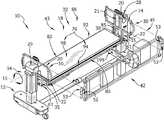
- FIG. 1is a perspective view of a surgical patient support system including a tower base connected to first and second patient support tops through main brackets;
- FIG. 2is a perspective view of a main bracket of the patient support system of FIG. 1 ;
- FIG. 3Ais a perspective view of the surgical patient support system of FIG. 1 showing a patient occupying the first patient support top while lying in a lateral position with knees bent and facing the second patient support top, and showing an H-shaped transfer sheet underlying the patient's torso, pelvis, and thighs;
- FIG. 3Bis a perspective view of the surgical patient support system of FIG. 1 with the main brackets having been rotated about 90 degrees relative to head end and foot end elevator towers such that the patient is supported by the second patient support top in a prone position;
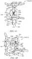
- FIG. 4Ais a cross-sectional elevation view taken along a line 4 A/ 4 B- 4 A/ 4 B of FIG. 3A showing the patient being laterally shifted with a transfer sheet from the solid line position to the dotted line position while lying in the lateral position to contact the second patient support top with an anterior side of the patient's body;
- FIG. 4Bis a cross-sectional elevation view taken along the line 4 A/ 4 B- 4 A/ 4 B of FIG. 3A showing the patient in contact with the second patient support top and secured with the transfer sheet to the second patient support top;
- FIG. 4Cis a cross-sectional elevation view taken along a line 4 C- 4 C of FIG. 3B showing that the patient has been rotated from the lateral position supported by the first patient support top into the prone position supported by the second patient support top;
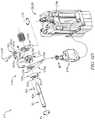
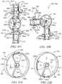
- FIG. 4Dis a perspective view of an exploded clutch rotation system of the tower base of the patient support system shown in FIG. 1 showing that the clutch rotation system includes a clutch having a lever connected to an actuator, and a clutch spindle configured to provide selective rotational-locking engagement between the lever and a mounting post, such that the mounting post can be selectively connected to the actuator for powered rotation or disconnected for free rotation;
- FIG. 5Ais a perspective view of another illustrative main bracket for use with the surgical patient support system of FIG. 1 showing that the main bracket includes a rotor and a pair of adjustment supports each including a vertically oriented slide body and a slide brace having handles, and each adjustment support is configured to connect to one of the first and second patient support tops;
- FIG. 5Bis a perspective view of the main bracket of the surgical patient support system of FIG. 5A showing that the adjustment support previously positioned at the 12 o'clock position shown in FIG. 5A has been selectively rotated to the 9 o'clock position and showing that the adjustment support positioned at the 6 o'clock position has had its slide brace selectively adjusted to a new radial position from a previous radial position shown in FIG. 5A ;
- FIG. 6is a perspective view of the main bracket of FIGS. 5A and 5B includes an attachment assembly that has been unlocked and showing that one of the adjustment supports has been pivoted away from the rotor;
- FIG. 7is a rear perspective view of the main bracket of FIGS. 5A-6 showing that the slide brace of one of the adjustment supports includes a position setting system for engaging position depressions of the slide body of the same adjustment support to lock the position of the slide brace relative to the slide body and showing that the slide brace includes a pair of support flanges pinned to the first patient support top;
- FIG. 8Ais cross-sectional view of one of the adjustment supports of the main bracket taken along the line 8 - 8 of FIG. 7 showing that the position setting system includes horizontal movable pins that are each arranged in a locked position within a position depression of the slide body to lock the position of the slide brace in position relative to the slide body;
- FIG. 8Bis cross-sectional view, similar to FIG. 8A , of the one adjustment support of the main bracket taken along the line 8 - 8 of FIG. 7 showing that the pins of the position setting system have been moved out of the position depressions to an unlocked position to unlock the position of the slide brace relative to the slide body;
- FIG. 9Ais a perspective view of a rotor of the adjustment support of the main bracket of FIGS. 5A-8B showing that the rotor includes a circular rotor body and a pair of bar mounts mounted to the rotor body for rotation about a horizontal central axis of the rotor and that each bar mount includes an engagement rod, and showing that the engagement rod of the bar mount presently arranged at the 12 o'clock position is in a disengaged position to selective unlock the bar mount for rotation around the central axis relative to the rotor body;
- FIG. 9Bis a perspective view of the rotor of the adjustment support of the main bracket of FIG. 9A showing that one of the bar mounts that was formerly arranged at the 12 o'clock position shown in FIG. 9A has been selectively rotated about the central axis to the 9 o'clock position, and showing that the engagement rod of the bar mount rotated to the 9 o'clock position has been moved into the engaged position to selectively lock the angular position of the bar mount relative to the rotor body;
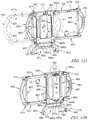
- FIG. 10Ais a perspective view of another illustrative main bracket for use in the surgical patient support system of FIG. 1 showing that the main bracket includes a rotor having a dish body and adjustment supports each having rails and a slide brace;
- FIG. 10Bis a perspective view of the main bracket of FIG. 10A showing that an angular position of the adjustment support that was formerly arranged in the 12 o'clock position shown in FIG. 10A has been selectively rotated to the 9 o'clock position, and showing that the radial position of the slide brace of the adjustment support presently positioned at the 6 o'clock position has been selectively adjusted to a new radial position;
- FIG. 11Ais a perspective view of the rotor of the main bracket of FIGS. 10A and 10B showing that the rotor includes support mounts arranged inside the dish body and having roller wheels arranged to contact an interior surface of the dish body;
- FIG. 11Bis a perspective view of the rotor of the main bracket of FIG. 11A showing that the support mount formerly arranged in the 12 o'clock position shown in FIG. 11A has been selectively rotated to the 9 o'clock position;
- FIG. 12Ais a perspective view of another illustrative main bracket for use in the surgical patient support system of FIG. 1 showing that the main bracket includes a main bracket frame and bracket rails coupled to the main bracket frame for sliding relative movement between a first right position (shown in solid line) and a second left position (shown in broken line) to provide selective arrangement of support to the second patient support top on either of the right or left lateral sides of the patient support system, respectively, and having a locking device configured to provide locking engagement between the bracket rails and the main bracket frame at each of the first and second positions;
- FIG. 12Bis a perspective view of the main bracket of FIG. 12A from a rear direction showing that the main bracket frame includes a connection mount configured to connect to the first patient support top, and showing that the main bracket frame is configured to connect to a connection bar;
- FIG. 12Cis a side view of the locking device of the main bracket of FIG. 12A showing the locking device in an unlocked position in which a biasing member is compressed and the locking device is positioned outside of a lock opening partly defined by each of the main bracket frame and one of the rail arms;
- FIG. 12Dis a side view of the locking device shown in FIG. 12B showing the locking device in a locked position in which a biasing member is extended and the locking device is positioned inside of the lock opening partly defined by each of the main bracket frame and one of the rail arms;
- FIG. 13is a perspective view of another illustrative embodiment of a patient support top for use in the surgical patient support system of FIG. 1 including a break assist bladder inflated by a pressurized fluid system, and showing that the first patient support top includes a pivotable leg portion arranged in a lowered position to provide leg break to a patient's body;
- FIG. 14Ais a perspective view of the patient support top of FIG. 13 showing that the break assist bladder is in a deflated state and the leg portion is in a raised position;
- FIG. 14Bis a perspective view of the patient support top of FIG. 13 showing that the break assist bladder is in the inflated state and the leg portion is in the lowered position to provide leg break to the patient's body;
- FIG. 15Ais a perspective view of a pad of the patient support top of FIG. 13 showing that the break assist bladder forms part of the pad and is attached on a bottom side thereof;
- FIG. 15Bis a perspective view of the pad shown in FIG. 15A from a lower perspective showing that the pad includes a sheath containing the break assist bladder and includes resilient straps configured to bias the assist bladder into the deflated state, and showing that the pad includes hook and loop fastener portions configured to releasably connect with other hook and loop fasteners portions disposed on the deck of the patient support system;
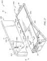
- FIG. 16Ais a perspective view of the patient support top of FIG. 13 showing that the support top includes an attachment sled (in broken line) disposed between the pad and a deck of the patient support top to connect the pad to the deck;
- FIG. 16Bis a perspective view of the patient support top shown in FIG. 16A with the pad removed and showing that the deck include a torso section and a foot section and that the attachment sled sliding connects to the foot section of the deck, and showing that the attachment sled and the torso section of the deck each include hook and loop fastener portions on a top side thereof configured for releasable attachment to the hook and look fastener portions of the pad;
- FIG. 17is a perspective view of the attachment sled shown in FIGS. 16A and 16B showing that the attachment sled has hooked ends each of which define a slot for receiving the foot section of the deck to permit sliding connection of the attachment sled to the deck;
- FIG. 18Ais a perspective view of the patient support top of FIG. 13 showing that the assist bladder is in the deflated position and the leg portion is in the raised position to create a zero leg break arrangement such that a patient occupying the patient support top while lying in the lateral position is positioned with the patient's spine generally aligned, and showing that the attachment sled is positioned between the deck and the pad to secure the pad to the deck and is in a first position along the leg portion of the deck;
- FIG. 18Bis a perspective view of the patient support top of FIG. 13 showing that the assist bladder is inflated at least partially and the leg portion of the patient support top is in the raised position to create a partial leg break arrangement such that the patient occupying the patient support top while lying in the lateral position is positioned with the patient's spine being slightly not aligned;
- FIG. 18Cis a perspective view of the patient support top of FIG. 13 showing that the assist bladder is in the inflated state and the leg portion of the support is in a lowered position to create a full leg break arrangement such that the patient occupying the patient support while lying in a lateral position is positioned to have the patient's spine generally not aligned, and showing that the attachment sled is position between the deck and the pad to secure the pad to the deck and has moved from the first position to a second position along the leg portion of the deck to accommodate the relative movement between the pad and the deck during change in state of the break assist bladder and change in position of the leg portion;
- FIG. 19is a perspective view of another embodiment of a patient support top for use in the surgical patient support system of FIG. 1 including a pad having a tiered support surface and an axilla support device for supporting a patient's axilla;
- FIG. 20is a perspective view from the lower right side of the patient support top as shown in FIG. 19 ;
- FIG. 21is perspective view of another embodiment of a patient support top for use in surgical patient support system of FIG. 1 including a patient securing device that secures the patient while lying in the lateral position to the patient support;
- FIG. 22is a side elevation view of the patient support top of FIG. 21 showing that the patient securing device includes straps and buckles configured for adjustably securing the patient to the patient support top;
- FIG. 23is a perspective view of a head strap of the patient support system of FIG. 1 that is configured to secure a patient's head to the patient support top showing that the head strap includes a strap body and fasteners that releasable couple opposite ends of the strap body to each other at various lengths; and
- FIG. 24is a perspective view of the head strap of FIG. 23 wrapped around the patient's head and around the prone patient support top to secure the patient's head thereto;
- FIG. 25is a perspective view of another illustrative surgical patient support system that includes a tower base and patient support tops attached to the tower base by main brackets;
- FIG. 26is a perspective view of one of the main brackets of the surgical patient support system of FIG. 25 showing that the main brackets includes a pair of main bracket rails that extend downwardly to a connection end for connecting with the lateral patient support tops and a prone bracket coupled to one of the main bracket rails and extending laterally to connect with the prone patient support top;
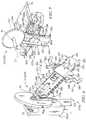
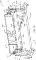
- FIG. 27is a perspective view of the lateral patient support top of the surgical patient support system of FIG. 25 showing that the patient support top includes a platform including a deck adapted for pivoting movement between raised and lowered positions to provide leg break to a patient lying on the patient support top in the lateral position and a pad (shown rotated to the left and rear to show the bottom surface) slidingly coupled to the deck by an attachment assembly to accommodate movement of the deck.
- a platformincluding a deck adapted for pivoting movement between raised and lowered positions to provide leg break to a patient lying on the patient support top in the lateral position and a pad (shown rotated to the left and rear to show the bottom surface) slidingly coupled to the deck by an attachment assembly to accommodate movement of the deck.
- Positioning the patient's body in one particular mannercan provide a surgical team preferred and/or appropriate access to particular surgical sites.
- a surgical teammay position a patient's body in various manners throughout the surgery.
- Patient supports, such as operating tables, that can accommodate various body positionsprovide surgical access to the surgical sites while safely supporting the patient's body.
- Some surgical proceduressuch as spinal fusion procedures, require particular access to various parts of a patient's spine.
- the course of a surgerycan require a patient's body to be positioned for a period of time in several different manners, for example, in a lateral position for a lateral lumbar interbody fusion and in a prone position for a posterior spinal fusion.
- Safely moving a surgical patient's body during surgerycan be challenging.
- Surgical support systemsthat can accommodate multiple positions of a patient's body while easing the transition between different positions provide safe and effective body positioning during a surgery.
- leg breakcan provide access to certain surgical sites, for example certain lumbar areas.
- the present disclosureincludes, among other things, surgical patient support systems for accommodating various positions of a patient's body, including for example a lateral position with leg break and a prone position.
- An illustrative embodiment of a surgical patient support system 10includes a tower base 12 , main brackets 14 , 16 , and patient support tops 18 , 42 as shown in FIG. 1 .
- Main brackets 14 , 16are configured to support patient support tops 18 , 42 at about 90 degrees relative to each other to support various patient body positions.
- Surgical patient support system 10includes head end 30 , a mid-section 32 , foot end 34 , and left 43 and right 45 lateral sides as shown in FIG. 1 .
- patient support top 18is configured to support a patient lying in a lateral position and patient support top 42 is configured to support the patient lying in a prone position.
- Tower base 12supports main brackets 14 , 16 for controlled translatable and rotational movement about an axis 15 .
- Tower base 12includes first and second elevator towers 28 , 29 as shown in FIG. 1 .
- First elevator tower 28is positioned at the head end 30 of the support system 10
- second elevator tower 29is positioned at the foot end 34 of the support system 10 .
- Each elevator tower 28 , 29includes one mounting post 41 .
- each mounting post 41is fixed for rotation with its connection bar 21 and is configured to be vertically translated by its elevator tower 28 , 29 and rotated by its elevator tower 28 , 29 about axis 15 for controlled rotation of connection bar 21 .
- Each mounting post 41extends from its elevator tower 28 , 29 to connect to main brackets 14 , 16 , illustratively through connection bar 21 .
- Axis 15is illustratively defined by a line intersecting both mounting posts 41 at their points of connection to connection bars 21 .
- Each connection bar 21is configured on opposite ends thereof to attach to one of main brackets 14 , 16 to provide moveable support thereto.
- Main brackets 14 , 16connect patient support tops 18 , 42 to tower base 12 respectively at a head end 30 and a foot end 34 of the support system 10 as suggested in FIG. 1 to provide adaptable support to a surgical patient.
- Main brackets 14 , 16each include a first bracket rail 20 , a second bracket rail 22 , and an extension bracket 35 as illustratively shown in FIGS. 1 and 2 .
- first and second bracket rails 20 , 22extend between left and right lateral sides 43 , 45 of patient support system 10 .
- Extension brackets 35 of each main brackets 14 , 16are configured for connection to patient support top 18 .
- Extension brackets 35are illustratively configured to connect patient support top 18 to each main bracket 14 , 16 to provide support to a patient lying in either of the lateral or supine positions as shown in FIGS. 1, 3A, and 3B .
- Each extension bracket 35includes a first extension bracket rail 36 and a second extension bracket rail 38 as shown in FIGS. 1 and 2 .
- the first and second extension bracket rails 36 , 38 of each extension bracket 35extend parallel to each other in spaced apart relation.
- the first and second extension bracket rails 36 , 38 of each main brackets 14 , 16extend perpendicularly from their respective second bracket rail 22 in a direction away from the first bracket rail 20 .
- first and second extension bracket rails 36 , 38illustratively extend coplanar with the first and second bracket rails 20 , 22 of their respective main bracket 14 , 16 .
- extension bracket 35 of each main bracket 14 , 16is attached to second bracket rail 22 such that each is illustratively arranged to extend beneath its respective bracket rail 22 to connect to patient support top 18 below the height of its respective bracket rail 22 in the orientation shown in FIGS. 1 and 3A .
- First and second extension bracket rails 36 , 38 of main brackets 14 , 16each have an attachment end 31 configured for attachment to second bracket rail 22 as suggested in FIG. 2 .
- Each extension bracket rail 36 , 38illustratively attaches to its respective second bracket rail 22 by a bolt 57 which penetrates through an attachment hole 59 in the bracket rail 22 for connection with end 31 of the respective extension bracket rail 36 , 38 .
- extension bracket rails 36 , 38are attached their respective second bracket rail 22 by one or more of riveting, welding, friction fit, shear pin, and/or any other suitable fastening manner.
- Extension bracket rails 36 , 38are illustratively substantially parallel with connection bar 21 and are spaced equidistantly on left and right lateral sides of connection bar 21 in the orientation as shown in FIG. 2 .
- First and second extension bracket rails 36 , 38each include a flanged section 37 located on another end 33 that is spaced apart from the attachment end 31 thereof as shown in FIG. 2 .
- Each extension bracket 35includes an extension bracket strut 40 extending perpendicularly to extension bracket rails 36 , 38 as shown in FIGS. 1 and 2 .
- Each extension bracket strut 40illustratively extends between and connects to the flanged sections 37 of the first and second extension bracket rails 36 , 38 of the same extension bracket 35 .
- First and second extension bracket rails 36 , 38 of each extension bracket 35include extension mount holes 49 for connecting the extension brackets 35 to patient support top 18 .
- Extension mount holes 49illustratively extend through the first and second extension bracket rails 36 , 38 in a direction parallel to the extension bracket strut 40 of the same extension bracket 35 as suggested in FIGS. 1 and 2 .
- a number of extension mount holes 49are illustratively disposed on end 33 of each first and second extension bracket rail 36 , 38 .
- the extension mount holes 49 of the first extension bracket rail 36are positioned in spaced apart relation to each other.
- Each extension mount hole 49 of first extension bracket rail 36illustratively corresponds in position to one extension mount hole 49 of the second extension bracket rail 38 of the same extension bracket 35 .
- Corresponding extension mount holes 49are configured to receive a connection pin 61 (see FIG. 3B ) therethrough for connection of patient support top 18 to the main brackets 14 , 16 via extension brackets 35 .
- Main brackets 14 , 16are configured to connect to prone support top 42 via first and second bracket rails 20 , 22 .
- First and second bracket rails 20 , 22 of each main bracket 14 , 16extend parallel to each other in spaced apart relation as shown in FIG. 2 .
- First and second bracket rails 20 , 22are embodied as rigid one-piece solid rails with portions extending between left and right side of connection bar 21 when rails 20 , 22 .
- Each first and second bracket rail 20 , 22includes a first end 25 and a second end 27 .
- Each first and second end 25 , 27 of bracket rails 20 , 22includes a flanged section 23 extending perpendicularly from its respective bracket rail 20 , 22 in a direction away from the patient support top 18 as suggested in FIGS. 1 and 2 .
- First and second bracket rails 20 , 22 of each main bracket 14 , 16include prone mount holes 20 a for coupling the main brackets 14 , 16 to prone patient support top 42 to support a patient while lying in prone position as suggested in FIG. 3B .
- Prone mount holes 20 aillustratively extend through the first and second bracket rails 20 , 22 in a vertical direction of patient support system 10 when oriented as shown in FIGS. 1 and 2 .
- a number of prone mount holes 20 aare illustratively disposed on each end 25 , 27 of first bracket rail 20 and a corresponding number of prone mount holes 20 a are illustratively disposed on each end 25 , 27 of second bracket rail 22 .
- Each prone mount hole 20 a on one end 25 , 27 of first bracket rail 20 of one main bracket 14 , 16illustratively corresponds in position to a prone mount hole 20 a on the same one end 25 , 27 of the second bracket rail 22 of the same main bracket 14 , 16 .
- Corresponding prone mount holes 20 a of the first and second brackets 20 , 22are configured to receive a connection pin 61 therethrough for connection of the lateral patient support top 42 to the main bracket 14 , 16 .
- Each of the main brackets 14 , 16includes first and second bracket struts 24 , 26 as shown in FIGS. 1 and 2 .
- Bracket struts 24 , 26extend parallel to each other between the first and second bracket rails 20 , 22 of each main bracket 14 , 16 .
- one first bracket strut 24connects to flanged section 23 on the first end 25 of first bracket rail 20 of main bracket 14 and to flanged section 23 of the first end 25 of second bracket rail 22 of the same main bracket 14 .
- One second bracket strut 26connects to flanged section 23 of the second end 27 of first bracket rail 20 of main bracket 14 and to flanged section 23 of the second end 27 of second bracket rail 22 of the same main bracket 14 .
- first bracket strut 24connects to flanged section 23 on the first end 25 of first bracket rail 20 of main brackets 16 and to flanged section 23 of the first end 25 of second bracket rail 22 of the same main bracket 16 .
- Another second bracket strut 26connects to flanged section 23 of the second end 27 of first bracket rail 20 of the same main bracket 16 and to flanged section 23 of the second end 27 of second bracket rail 22 of the same main bracket 16 .
- Long handles 141 , 143are coupled respectively to struts 24 , 26 at the ends 25 , 27 of main brackets 14 , 16 as shown in FIGS. 1 and 2 .
- Each main bracket 14 , 16is illustratively connected to its connection bar 21 by a handle 133 having a pair of parallel pins 135 extending therefrom as shown in FIGS. 1 and 2 .
- Pins 135are each respectively inserted through corresponding holes 137 of rails 20 , 22 and through bores (not shown) provided through the long dimension of connection bar 21 .
- handle 133is closely adjacent to one of the rails 20 , 22 of the main bracket 14 , 16 and latches 139 mounted to the distal ends of pins 135 are exposed for manipulation adjacent to the other rail 20 , 22 of the same main bracket 14 , 16 .
- Latches 139are pivotable between unlocked and locked positions, the locked position (shown in FIG. 2 ) preventing disconnection for handle 133 and pins 135 from the main bracket 14 and the unlocked position allowing removal of pins 153 from their respective holes 137 .
- Prone patient support top 42is configured to connect to the main brackets 14 , 16 to provide a prone support surface 56 to permit engagement with the anterior side of a patient's body while in the lateral position as suggested in FIGS. 3A, 4A, and 4B .
- prone patient support top 42is illustratively arranged perpendicular to the patient support top 18 .
- Prone patient support top 42includes a prone frame 47 and prone pads 54 .
- Prone frame 47includes first and second prone support rails 44 , 46 and first and second prone mount rails 48 , 50 .
- First and second prone support rails 44 , 46extend parallel to each other in spaced apart relation from the head end 30 to the foot end 34 of patient support system 10 as shown in FIG. 3A .
- prone rails 44 , 46are illustratively embodied as straight tubular frame members, but in some embodiments are any of solid and/or filled frame members.
- First and second prone rails 44 , 46extend between and connect to prone mount rails 48 , 50 arranged respectively at the head end 30 and foot end 34 of patient support system 10 to form prone frame 47 as shown in FIGS. 3A and 3B .
- First and second prone mount rails 48 , 50each includes a prone connection limb 52 configured for engagement with the main brackets 14 , 16 and for limited movement to permit rotatable connection of patient support top 42 to tower base 12 .
- the movable connection of main brackets 14 , 16 to prone connection limb 52permits rotation of main brackets 14 , 16 about axis 15 while the elevator towers 28 , 29 are arranged to have their mounting posts 41 at different elevations above the floor, without binding the connections.
- An example of such a movable connection of a patient table to a support structureis disclosed in U.S. Patent Application Publication No. 2013/0269710 by Hight et al., the contents of which are hereby incorporated by reference as described for motion coupler “218” and similar descriptions therein.
- Each prone connection limb 52includes a prone pin tube 53 attached to an end of the prone connection limb 52 that is positioned away from the respective prone mount rail 48 , 50 as suggested in FIG. 3A .
- the prone pin tube 53illustratively extends through the prone connection limb 52 and is configured for selective engagement of corresponding prone mount holes 20 a of first and second bracket rails 20 , 22 .
- a connection pin 61penetrates through the corresponding prone mount holes 20 a and the prone pin tube 53 to movably connect the patient support top 42 to main brackets 14 , 16 .
- patient support top 42connects to each of the main brackets 14 , 16 at the head end 30 and foot end 34 of surgical patient support system 10 as shown in FIGS. 3A and 3B .
- Patient support top 42illustratively connects to each of the first and second bracket rails 20 , 22 of each main bracket 14 , 16 by pinned connection described above.
- patient support top 42is selectively connected to first and second bracket rails 20 , 22 of each main bracket 14 , 16 on a right lateral side 45 of the patient support device, but can alternatively be selectively connected to first and second bracket rails 20 , 22 of each main bracket 14 , 16 on a left lateral side 43 of the patient support device.
- Prone patient support top 42is support by the main brackets 14 , 16 at about 90 degrees relative to patient support top 18 .
- Patient support top 18is configured to provide support to a patient in any of the supine and the lateral positions as shown in FIG. 1 .
- Patient support top 18is connected to elevator towers 28 , 29 through the main brackets 14 , 16 .
- Patient support top 18illustratively includes a frame 74 and a platform 76 .
- Frame 74 of patient support top 18includes support rails 80 , 82 and mount rails 84 , 86 as shown in FIGS. 1 and 3-5 .
- Support rails 80 , 82extend parallel to each other in spaced apart relation from the head end 30 to the foot end 34 of patient support system 10 .
- Support rails 80 , 82extend between and connect to mount rails 84 , 86 that are disposed respectively at the head end 30 and foot end 34 to form a rigid structure.
- Each mount rail 84 , 86includes a moveable connection limb 85 that is configured for connection with one of main brackets 14 , 16 .
- connection limbs 85are illustratively embodied as having similar construction to prone connection limb 52 and an example of such a movable connection of a patient table to a support structure is disclosed in U.S. Patent Application Publication No. 2013/0269710 by Hight et al., the contents of which are hereby incorporated by reference as described for motion coupler “218” and similar descriptions therein.
- connection limb 85includes a pin tube 39 attached to an end of the connection limb 85 that is positioned away from the respective mount rail 84 , 86 as suggested in FIG. 1 .
- Each pin tube 39extends through its respective connection limb 85 and is configured for selective engagement of corresponding mount holes 49 of one extension bracket 35 of main brackets 14 , 16 .
- a connection pin 61penetrates through the corresponding mount holes 49 and pin tube 39 to movably connect patient support top 18 to main brackets 14 , 16 to support a patient while lying in any of the supine and the lateral positions.
- Elevator towers 28 , 29provide movable support to the respective main brackets 14 , 16 .
- Elevator towers 28 , 29are configured to vertically translate and rotate their mounting posts 41 such that each of the head end 30 and foot end 34 of patient support top 18 and patient support top 42 can be independently translated vertically, and such that the patient support tops 18 , 42 can be rotated around axis 15 together in fixed position relative to each other as suggested in FIGS. 3A-4C .
- main brackets 14 , 16are operable for controlled rotation around axis 15 via connection bars 21 to move a patient between positions, for example, from the lateral position into the prone position.
- a patient occupying patient support top 18 while lying in the lateral positionis shifted laterally (from the solid line position to the dotted line position in FIG. 4A ) to place her anterior side into contact with prone support surface 56 of patient support top 42 while a lateral side is supported by patient support top 18 as shown in FIGS. 4A and 4B .
- a usercan operate towers 28 , 29 to rotate mounting posts 41 such that main brackets 14 , 16 are illustratively rotated towards the right lateral side 45 around axis 15 until the patient achieves the prone position supported by patient support top 42 as shown in FIGS.
- the controlled rotation and translation of the mounting posts 41is embodied to be performed by an elevator control system.
- the elevator control systemis embodied to include a user interface, controller, and associated peripherals including hardware and/or software/firmware to allow a user to selectively perform controlled rotation and translation of the mounting posts 41 .
- An example of such a control systemis described in U.S. Patent Application Publication No. 2013/0269710 by Hight et al., the contents of which are hereby incorporated by reference as described for control system “30” and similar descriptions therein.
- towers 28 , 29each have a clutch rotation system 171 , as shown in FIG. 4D , including a powered actuator 173 which is operable to provide a limited ranged of powered rotation to mounting posts 41 to tilt main brackets 14 , 16 and thereby tilt patient support top 18 side-to-side. If presently attached, as described herein, the prone patient support top 42 also undergoes the limited amount of powered tilt.
- Mounting posts 41are illustratively selectively locked for limited powered rotation relative to their respective elevator towers 28 , 29 by the clutch rotation system 171 that can be unlocked to permit manual (free) rotation of mounting posts 41 and main brackets 14 , 16 , and thus support tops 18 , 42 , through a larger rotational range, for example, plus and minus 90 degrees and or more.
- An example of such a clutch rotation systemis described in U.S. Patent Application Publication No. 2013/0269710 by Hight et al., the contents of which are hereby incorporated by reference as described for rotation system “46” and similar descriptions therein.
- Clutch rotation system 171includes powered actuator 173 , clutch 175 , and mounting post 41 , as shown in FIG. 4D .
- Clutch 175includes a mounting post ring 41 b , an actuator lever 175 a , a clutch spindle 177 , and a spindle housing 179 .
- Actuator lever 175 ais pivotably connected at one end to actuator 173 and is mounted at the other end for pivoting rotation about axis 15 .
- Mounting post ring 41 bis fixed against rotation with mounting post 41 by a key 41 c being inserted in a key slots 41 d , 41 e of the mounting post ring 41 b and mounting post 41 , respectively.
- Mounting post ring 41 bincludes finger holes 41 f each configured to receive a clutch finger 177 a of the clutch spindle 177 .
- Finger holes 41 f of mounting post ring 41 bare illustratively arranged in corresponding radial position to holes 175 b of actuator lever 175 a .
- clutch fingers 177 aare selectively inserted through each of finger holes 41 f and holes 175 b , mounting post ring 41 b is fixed against rotation relative to actuator lever 175 a.
- Spindle housing 179defines a recess 179 b configured to receive clutch spindle 177 for limited rotation therein as suggested in FIG. 4D .
- Spindle housing 179includes tracks 179 c for receiving screws 179 d therethrough for connection to clutch spindle 177 .
- Screws 179 dare illustratively arranged to insert into clutch spindle 177 at opposite radial positions about 180 degrees from each other, each through tracks 179 c to connect clutch spindle 177 to spindle housing 179 with limited relative rotation therebetween to prevent binding during pivoting movement of spindle housing 179 about a post 179 e.
- Spindle housing 179is mounted on one end to post 179 e that is vertically mounted on the respective tower 28 , 29 for pivoting movement about axis 115 as shown in FIG. 4D .
- Spindle housing 179includes a handle 179 f extending from another end and extending through a plate 181 of the respective tower 28 , 29 for selective operation by a user.
- Plate 181defines a guide track 181 a having a first track position 181 b and a second track position 181 c as suggested in FIG. 4D .
- Spindle housing 179includes a biasing member 183 configured to bias spindle housing 179 and clutch spindle 177 such that clutch fingers 177 a are inserted into corresponding ones of holes 41 f , 175 b to fixed relative rotation of (rotationally-lock) actuator lever 175 a and mounting post ring 41 b about axis 15 and thus fix relative rotation between mounting post 41 and the actuator lever 175 a about axis 15 such that the actuator 173 provides controlled rotational positioning of mounting post 41 .
- the biasing member 183is extended to bias spindle housing 179 to pivot about axis 115 such that the clutch spindle 177 is in an engaged position such that the clutch fingers 177 a are inserted into the finger holes 41 f and corresponding holes 175 b such that rotation of the mounting post 41 is controlled by actuator 173 .
- clutch spindle 177includes four clutch fingers 177 a ; and clutch fingers 177 a , finger holes 41 f , and holes 175 b are each disposed at equal radial distance from axis 15 and at equal circumferential spacing from each other such that finger holes 41 f align with holes 175 b and clutch fingers 177 a at each 90 degree interval of rotation of mounting post 41 relative to actuator lever 175 a .
- Such arrangementpermits mounting post 41 , and thus connection bar 21 and main brackets 14 , 16 , to be locked for controlled powered rotation by actuator 17 embodied as a linear actuator.
- Handles 133 and long handles 141 , 143are configured to be easily gripped by a user to perform the manual rotation.
- the limited powered rotationis embodied to be about plus and minus 25 degrees of tilt, but in some embodiments is any amount of powered rotation.
- the mounting post 41are configured for powered rotation of plus and minus 90 degrees and or more.
- patient support 18is configured for pinned connection to the extension brackets 35 and patient support 42 is configured for pinned connection to the first and second bracket rails 20 , 22 .
- patient supports 18 , 42may each be configured for selective pinned connection to both extension brackets 35 and first and second bracket rails 20 , 22 , for example, pin tubes 39 , 53 and the distance between corresponding holes 20 a , 49 may be arranged to corresponding such that each pin tube 39 , 53 can be selectively pinned to any corresponding holes 20 a , 49 by one connection pin 61 .
- the patient support system 10in place of main brackets 14 , 16 , respectively includes main brackets 214 , 216 as shown in FIGS. 5A-9B .
- Main brackets 214 , 216are configured for use in patient support system 10 in lieu of main brackets 14 , 16 .
- Main brackets 214 , 216connect to tower base 12 and respectively to patient support tops 18 , 42 .
- Main brackets 214 , 216are configured to provide angular and radial position adjustment of the patient support tops 18 , 42 , as shown in FIGS. 5A and 5B .
- Each main bracket 214 , 216includes a rotor 224 and adjustment supports 225 a , 225 b .
- Main brackets 214 , 216connect patient support tops 18 , 42 to tower base 12 to provide selective adjustment of the angular and radial position of each patient support top 18 , 42 about axis 15 .
- Each rotor 224 of main brackets 214 , 216is configured to connect to the mounting post 41 of one of the elevator towers 28 , 29 , without any connection bar 21 as shown in FIG. 6 .
- head end adjustment supports 225 a , 225 bare mounted to the rotor 224 of main bracket 214
- foot end adjustment supports 225 a , 225 bare mounted to the rotor 224 of the other main bracket 216 .
- adjustment supports 225 a of each of main brackets 214 , 216correspond to and are configured to connect to patient support top 18 ; and the other adjustment supports 225 b of each of the main brackets 214 , 216 correspond to and are configured to connect to patient support top 42 to provide selective adjustment of the angular and radial position of each patient support top 18 , 42 about an axis 217 illustratively defined through the center of rotor 224 as shown in FIGS. 5A and 5B .
- a usercan selectively change the radial position of either of patient support tops 18 , 42 relative to axis 217 as suggested by arrows 299 a , 299 b shown in FIGS. 5A and 5B .
- a usercan change the radial position of patient support top 18 by unlocking the position setting system 282 of each of the adjustment supports 225 a of each main bracket 214 , 216 ; adjusting the radial position of those adjustment supports 225 a of each of main bracket 214 , 216 to a new radial position relative to axis 217 ; and locking position setting systems 282 of adjustment supports 225 a of each main bracket 214 , 216 at the new radial position.
- each adjustment support 225 a , 225 b at either one of the head end 30 or foot end 34are configured for independent radial adjustment without adjustment of the radial position of the adjustment supports 225 a , 225 b at the other one of the head end 30 or foot end 34 .
- Adjustment supports 225 a , 225 bare configured to permit user selectable adjustment of the radial position of the patient support tops 18 , 42 relative to axis 217 without requiring removal of connection pin 61 as suggested in FIG. 7 . Adjustment of the radial position of the patient support tops 18 , 42 without removal of the connection pin 61 permits controlled radial adjustment of patient support tops 18 , 42 without disconnection of the patient support tops 18 , 42 from elevator towers 28 , 29 .
- Each adjustment support 225 a , 225 bincludes a slide bar 223 having a slide body 260 and a slide brace 262 engaged with slide body 260 and configured for selectable positioning relative to slide body 260 as suggested in FIGS. 5A and 5B .
- Each slide body 260includes first and second ends 263 , 264 , a front side 253 , lateral sides 255 , 257 , and a back side 259 as shown in FIGS. 6 and 7 .
- Each slide body 260is configured to be secured at its first end 263 to the one of the rotors 224 .
- Each slide body 260includes a main body 266 and connection arms 268 as shown in FIGS. 5A, 5B, and 8 .
- Each main body 266extends from second end 264 of slide body 260 towards the first end 263 of slide body 260 to a release end 265 of main body 266 .
- Connections arms 268extend from release end 265 of their main body 266 towards first end 263 of their main body 266 .
- Connection arms 268extend from the main body 266 parallel to each other and in spaced apart relation to define a gap 267 therebetween.
- Each slide body 260includes a connection member 270 , illustratively embodied as a shaft, connected to its connection arms 268 and configured for attachment to rotor 224 .
- Each slide body 260includes position depressions 280 distributed along lateral sides 255 , 257 thereof as shown in FIGS. 6 and 7 .
- Position depressions 280are illustratively embodied as circular holes defined in opposing lateral sides 255 , 257 of slide body 260 and configured for engagement with the position setting system 282 of the attachment supports 225 a , 225 b .
- Position depressions 280 on either lateral side 255 , 257are illustratively disposed at equally spaced apart intervals from each other, but in some embodiments are disposed at varying intervals, for example, graduated intervals.
- position depressions 280may have any shape and/or size complimentary to the position setting system 282 to permit selective locking of the position of the slide brace 262 relative to the slide body 260 .
- Each slide body 260includes stop posts 261 projecting perpendicularly outward from either lateral side 255 , 257 on second end 264 to prevent disengagement of the slide brace 262 from the slide body 260 on the second end 264 .
- Each slide brace 262includes one position setting system 282 for selectively locking the position of slide brace 262 along the slide body 260 by engagement of position setting system 282 with position depressions 280 as shown in FIGS. 7, 8A, and 8B .
- Each slide brace 262includes a brace body 284 , extension housings 286 , support flanges 288 , and handles 290 .
- Brace body 284engages its corresponding slide body 260 for selective radial positioning.
- Each brace body 284is configured to extend around its slide body 260 as shown in FIG. 7 .
- Brace body 284is illustratively embodied to have a C-shape when viewed in a radial direction with respect to axis 217 .
- Brace body 284includes front portion 284 a , side portions 284 b , 284 c , and back portions 284 e , 284 f , each disposed to extend across the respective front 253 , sides 255 , 257 , and back 259 of the slide body 260 as shown in FIGS. 6 and 7 .
- Side portions 284 b , 284 ceach include a bore 285 penetrating therethrough and configured for selective alignment with position depressions 280 on corresponding lateral sides 255 , 257 of slide body 260 to permit engagement of position setting system 282 with position depressions 280 as shown in FIGS. 8A and 8B .
- Each side portion 284 b , 284 cis configured to connect to one of the extension housings 286 .
- Extension housings 286each includes a base 286 a , a main body 286 b , and an extension body 286 c as shown in FIGS. 7, 8A, and 8B .
- Base 286 aillustratively connects to one of the side portions 284 b , 284 c of one of the brace bodies 284 .
- Base 286 ais illustratively embodied as a plate having an opening 287 defined therein.
- Each main body 286 bhas a first end connected to its base 286 a as shown in FIGS. 8A and 8B .
- Main body 286 bextends from base 286 a in a direction away from the brace body 284 to connect with extension body 286 c on the other end positioned away from the base 286 a .
- Main body 286 bis illustratively embodied as a cylinder having a first outer diameter.
- Each extension body 286 cis connected to its main body 286 b and extends from the main body 286 b in a direction away from the brace body 284 as shown in FIGS. 8A and 8B .
- Extension body 286 cextends parallel to its main body 286 b in a direction away from brace body 284 .
- extension body 286 cis a cylinder having a second outer diameter, smaller than the first outer diameter of main body 286 b , and extending coaxial with the main body 286 b .
- Each extension housing 286includes a cavity 296 defined therein and extending through each of base 286 a , main body 286 b , and extension body 286 c.
- Cavities 296 of extension housings 286 of each adjustment support 225 a , 225 bare configured to house the position setting system 282 .
- Each cavity 296is illustratively embodied as a cylindrical cavity extending through a center of extension housing 286 from the interface between base 286 a and its connected side portion 284 b , 284 c in a direction away from the brace body 284 .
- Each cavity 296is illustratively defined by a first cavity diameter 296 a defined within each of base 286 a and main body 286 b , and a second cavity diameter 296 b defined within extension body 286 c as shown in FIG. 8A .
- a step 215is defined by the interior of the extension housing 286 to support operation of position setting system 282 as shown in FIGS. 8A and 8B .
- steps 215are embodied as an interior circumferential flat surface facing toward base 286 a and configured to engage with position setting system 282 .
- Each adjustment support 225 a , 225 bincludes a position setting system 282 .
- Position setting system 282is configured for selective engagement with position depressions 280 of its corresponding slide bar 223 to provide selective locking of the position of slide brace 262 relative to slide body 260 as shown in FIGS. 8A and 8B .
- Position setting system 282includes position setting pins 292 and return devices 294 .
- Position setting pins 292are arranged within cavity 296 of the extension housings 186 in engagement with return devices 294 for resilient positioning of the pins 292 between an engaged position ( FIG. 8A ) and a disengaged position ( FIG. 8B ).
- Position setting pins 292 of each position setting system 282are illustratively embodied as elongated cylindrical pins having an outer portion 292 a , a center portion 292 b , and the engagement portion 292 c as shown in FIG. 8A .
- Each outer portion 292 aillustratively includes a diameter corresponding to the second cavity diameter 296 b of the corresponding extension body 286 c and configured for sliding engagement with interior portions of the extension body 286 c which define the cavity 296 b as suggested in FIGS. 8A and 8B .
- Each center portion 292 billustratively includes a diameter corresponding to the first cavity diameter 296 a of the corresponding main body 286 b and configured for sliding engagement with interior portions of base 286 a and main body 286 b which define cavity 296 as suggested in FIGS. 8A and 8B .
- Each center portion 292 bincludes a lateral face 293 configured for engagement with an outer surface of the corresponding side portion 284 b , 284 c in the engaged position as shown in FIG. 8A .
- Each engagement portion 292 cillustratively includes a diameter corresponding to a diameter of bore 285 of corresponding side portions 284 b , 284 c and configured for sliding engagement with interior portions of side portions 284 b , 284 c which define bore 285 as suggested in FIGS. 8A and 8B .
- Return devices 294are configured to engage their respective position setting pins 292 to provide resilient return force as suggested in FIGS. 8A and 8B .
- Each return device 294is illustratively embodied as a mechanical spring that encircles the outer portion 292 a of different ones of the pins 292 .
- Each return device 294is illustratively engaged with step 215 of the corresponding extension housing 286 and is engaged with the respective center portion 292 b of the respective pin 292 to provide spring loaded return of the pins 292 to their engaged positions.
- return devicesmay include any one or more of resilient material, gas spring, and/or any other device suitable for returning pins 292 to their engaged positions.
- return devices 294may be omitted in favor of user driven manual return of pins 292 to their engaged positions.
- engagement portions 292 c of pins 292are inserted into one of the position depressions 280 of the slide bar 223 to lock movement of the slide brace 262 relative to the slide bar 223 as shown in FIG. 8A .
- engagement portions 292 c of pins 292are positioned outside of position depressions 280 to unlock movement of the slide brace 262 relative to the slide bar 223 as shown in FIG. 8B .
- both pins 292 of the respective slide brace 262must be maintained in their disengaged position.
- Each position setting pin 292is connected to a trigger 298 , shown in FIG. 7 , that extends through its respective handle 290 for user driven operation.
- a usercan illustratively operate triggers 298 to change the position of the pins 292 , for example, against the return force of return devices 294 to disengage the pins 292 .
- a usercan selectively operate the position setting system 282 to unlock the adjustment supports 225 a , 225 b as suggested in FIGS. 6-8B .
- a usermoves triggers 298 of the same slide brace 262 in a direction away from slide bar 360 which moves position setting pins 292 out of engagement with position depressions 280 against the force of return devices 294 .
- the usercan selectively move the slide brace 262 relative to slide body 260 into a different radial position relative to axis 217 .
- the usercan release the triggers 298 to permit position setting pins 292 to be forced by return devices 294 back into engagement with position depressions 280 corresponding to the radial position, locking the position of the slide brace 262 relative to the slide body 260 .
- the usercan perform radial positioning of slide brace 262 relative to slide body 260 while a patient support top 18 , 42 is connected to support flanges 288 to provide radial adjustment of the patient support top 18 , 42 relative to axis 217 .
- a usercan selectively change the angular position of any patient support top 18 , 42 about axis 217 as suggested by arrows 289 b .
- a usercan change the angular position of patient support top 18 by unlocking rotors 224 of each main bracket 214 , 216 , adjusting the angular position of the adjustment supports (rotating about axis 217 ) of each of main bracket 214 , 216 to a different angular position, and locking the rotors 224 of each main bracket 214 , 216 .
- Each rotor 224is connected and rotationally fixed with the mounting post 41 of one of the elevator towers 28 , 29 such that axis 15 and axis 217 are aligned as coaxial when mounting posts 41 of each elevator tower 28 , 29 are configured at the same elevation above the floor as suggested in FIG. 6 .
- Each rotor 224includes a rotor body 226 and bar mounts 228 a , 228 b configured for selective angular positioning relative to body 226 as shown in FIGS. 5A, 5B, 9A, and 9B .
- Bar mounts 228 a , 228 bare each configured to mount onto rotor body 226 and to connect to one of the patient support tops 18 , 42 as shown in FIGS. 9A and 9B . Selective movement of bar mounts 228 a , 228 b causes commensurate movement of the connected patient support tops 18 , 42 as explained below.
- Each rotor body 226is illustratively embodied as a circular flat disk having a center hole 227 configured to receive the mounting post 41 of one elevator tower 28 , 29 as suggested in FIGS. 9A and 9B .
- Each rotor body 226defines a front surface 229 , a back surface 230 , and a circumferential surface 232 .
- Circumferential surface 232includes depressions 234 defined therein. Depressions 234 are illustratively disposed evenly at 90 degree angular intervals relative to each other on circumferential surface 232 , but in some embodiment are disposed at 45 degree intervals and/or are disposed at uneven intervals, for example, graduated intervals decreasing in spacing with decreasing distance from the 6 o'clock position.
- Depressions 234are each configured to receive an engagement rod 254 , shown in FIG. 9A , of bar mounts 228 a , 228 b therein for selective locking of the angular position of bar mounts 228 a , 228 b relative their to rotor body 226 .
- First bar mount 228 ais illustratively arranged at the 6 o'clock position and second bar mount 228 b is arranged at the 12 o'clock position as shown in FIG. 9A .
- Bar mounts 228 a , 228 bcan be selectively unlocked from the rotor 224 and adjusted in angular position around axis 217 .
- second bar mount 228 bcan be disengaged from the rotor body 226 and rearranged in the 9 o'clock position as shown in FIG. 9B . This permits selectable arrangement of the position of the patient support tops 18 , 42 to support surgical site access to a patient's body.
- Each bar mount 228 a , 228 bis configured to rotatably mount onto the rotor body 226 by connection with the respective mounting post 41 while inserted into the center hole 227 as shown in FIGS. 9A and 9B .
- Each bar mount 228 a , 228 bincludes a mount body 233 and a connection head 236 .
- Each mount body 233includes a first body section 238 and a second body section 240 .
- First body section 238 of each bar mount 228 a , 228 bis illustratively embodied as a plate having a front side 242 , a back side 244 , and a radially outer surface 245 as shown in FIGS. 9A and 9B .
- First body section 238illustratively defines a thickness d between the front side 242 and the back side 244 .
- First body section 238is illustratively arranged to extend radially between mounting post 41 and circumferential surface 232 .
- connection head 236connects its bar mount 228 a , 228 b to the respective mounting post 41 as shown in FIGS. 9A and 9B .
- connection heads 236are embodied to have a thickness half d/2, and each connection head 236 is embodied to be offset from a symmetric center of first body section 238 along the direction of axis 217 .
- connection head 236 of bar mount 228 ais offset in direction closer to rotor 224 and the connection head of bar mount 228 b of the same rotor 224 is offset farther from the rotor 224 such that both connection heads are stacked on the mounting post 41 to have a combined width equal to with d of first body section 238 .
- Second body section 240 of each bar mount 228 a , 228 bis connected to and extends from the front side 242 of first body section 238 as shown in FIGS. 9A and 9B .
- second body section 240extends from near the connection head 236 of first body section 238 radially outward to a radially outward end 239 arranged at a position about radially equal to the circumferential surface 232 of the rotor 224 and about radially equal to the radially outer surface 245 of first body section as shown in FIGS. 9A and 9B .
- Each second body section 240includes a flange 250 and defines a cradle 251 .
- Each flange 250extends perpendicularly from the outward end 239 of the second body section 240 parallel to axis 217 and in a direction towards the back surface 230 of the rotor 224 as shown in FIG. 9A .
- Flange 250 of each bar mount 228 a , 228 bdefines a radial surface 246 that is radially outward from the second body section 240 and a radially inward surface 248 .
- at least a portion of radially inward surface 248 of flange 250is connected to radially outer surface 245 of first body section 238 as shown in FIGS. 9A and 9B .
- Flange 250illustratively extends from the second body section 240 across the first body section 138 and across the circumferential surface 232 of the rotor 224 as shown in FIGS. 9A and 9B .
- Each flange 250includes a rod receiver 247 and an engagement rod 254 slidably mounted within the receiver 247 as shown in FIGS. 9A and 9B .
- Rod receiver 247illustratively extends in a radially outward direction from radial surface 246 at a position along axis 217 corresponding to the circumferential surface 232 .
- Flange 250 and receiver 247together define a rod bore 249 that continuously extends radially outward from inward surface 248 and penetrates through rod receiver 247 .
- Rod bore 249is configured to slidably receive engagement rod 254 .
- Each engagement rod 254is configured for selective engagement with depressions 234 to selectively lock the angular position of the respective bar mount 228 a , 228 b relative to its rotor 224 .
- Engagement rod 254 of each flange 250includes a rod head 254 a and rod 254 b extending from rod head 254 a as shown in FIG. 9A .
- Rod head 254 ais illustratively spherical and rod 254 b is illustratively cylindrical, but in some embodiments, rod head 254 a and rod 254 b may each have any shape suitable for selective engagement of engagement rod 254 with depressions 234 to selectively lock the angular position of the respective bar mount 228 a , 228 b relative to its rotor 224 .
- Each engagement rod 254is slidable between an engaged position ( FIG. 8B ) in which the engagement rod 254 is inserted into one of the depressions 234 of the corresponding rotor 224 , and a disengaged position ( FIG. 8A ) in which the engagement rod 254 is retracted out of the depressions 234 of the corresponding rotor 224 to provide selectable locking of the bar mounts 228 a , 228 b relative to the rotor body 226 .
- the engagement rod 254 of one of the bar mounts 228 a , 228 bis in the engaged position, the corresponding bar mount 228 a , 228 b is fixed against rotation relative to the rotor body 226 .
- Engagement rod 254 of one of the bar mounts 228 a , 228 bWhen the engagement rod 254 of one of the bar mounts 228 a , 228 b is in the disengaged position, the corresponding bar mount 228 a , 228 b can rotate relative to the rotor body 226 . Engagement rods 254 are biased toward the engaged position by a suitable biasing member such as a spring located inside receiver 247 .
- each flange 250includes an opening 252 configured to receive attachment rods 274 of slide bars 223 to secure the one of the slide bars 223 to the rotor 224 .
- Opening 252illustratively extends radially inward toward axis 217 from radially outward surface 246 of its flange 250 .
- Opening 252is illustratively positioned on the radially outward surface 246 in a location away from rod receiver 247 in the direction of axis 217 .
- Opening 252is arranged with a corresponding position along axis 217 to that of cradle 251 on opposite radial ends of second body section 240 to secure the corresponding slide bar 223 to the rotor 224 .
- Each cradle 251is defined by a radially inward surface 253 of its second body section 240 and is configured to receive connection member 270 of one slide bar 223 as shown in FIGS. 5A-6, 8, 9A, and 9B .
- Cradle 251is illustratively embodied as a concave cylindrical surface that extends perpendicular to the axis 217 and parallel to the front side 242 of first body section 238 as shown in FIGS. 9A and 9B .
- Cradle 251is illustratively complimentary in shape and size to connection member 270 of adjustment supports 225 a , 225 b .
- each bar mount 228 a , 228 btogether function to secure one of the adjustment supports 225 a , 225 b to the rotor 224 through their respective engagements with connection member 270 and attachment rod 274 of one of the adjustment supports 225 a , 225 b.
- adjustment supports 225 a , 225 beach include one connection member 270 and one attachment assembly 272 .
- Connection member 270 of each adjustment support 225 a , 225 bextends through gap 267 and connects to each of connections arms 268 of the same slide body 260 at the first end 263 thereof.
- Connection member 270is illustratively embodied as a cylinder extending from one connection arm 268 to the other of the same slide body 260 .
- Each connection member 270is illustratively shaped and sized complimentary to cradle 251 .
- connection member 270is configured to secure its slide body 260 to a bar mount 228 a , 228 b by seating within cradle 251 of the bar mount 228 a , 228 b and in combination with engagement of its attachment assembly 272 with the bar mount 228 a , 228 b as suggested in FIG. 6 .
- Attachment assembly 272 of each adjustment support 225 a , 225 bincludes attachment rod 274 and a release button 276 as shown in FIG. 8 .
- Each attachment assembly 272is configured to secure its respective adjustment support 225 a , 225 b to bar mounts 228 a , 228 b .
- Each attachment rod 274illustratively extends from the release end 265 of main body 266 between connection arms 268 towards first end 263 of slide body 260 of its respective adjustment support 225 a , 225 b.
- Each attachment rod 274is configured for slidable movement between a retracted position ( FIG. 8B ) and an extended position ( FIG. 8A ).
- attachment rod 274projects from its slide body 260 into gap 267 for penetration into opening 252 of one of the bar mounts 228 a , 228 b to secure its adjustment support 225 a , 225 b thereto.
- attachment rod 274is arranged within slide body 260 and does not penetrate into the opening 252 of the bar mount 228 a , 228 b such that the slide bar 223 can be pivoted out of engagement with the bar mount 228 a , 228 b as suggested in FIG.
- Release button 276is connected to the attachment rod 274 and configured for selectable movement by a user between engaged ( FIG. 8A ) and disengaged ( FIG. 8B ) positions to operate the attachment rod 274 between its extended and retracted positions, respectively.
- Each release button 276is illustratively received within a cavity 278 of the main body 166 of its slide bar 223 and configured for user interface operation.
- Button 276 and attachment rod 274 of each attachment assembly 272are biased toward their respective engaged and extended positions by a suitable biasing member such as a spring located in cavity 278 .
- the patient support system 10in place of main brackets 14 , 16 , and main brackets 214 , 216 , the patient support system 10 includes main brackets 314 , 316 as shown in FIGS. 10A and 10B .
- Main brackets 314 , 316are configured for use in patient support system 10 and are similar to main brackets 214 , 216 as shown in FIGS. 5A-9B and described herein. Accordingly, similar reference numbers in the 300 series indicate features that are common between main brackets 214 , 216 and main brackets 314 , 316 unless indicated otherwise.
- the description of main brackets 214 , 216is equally applicable to main brackets 314 , 316 except in instances when it conflicts with the specific description and drawings of main brackets 314 , 316 .
- Each main bracket 314 , 316connects to tower base 12 by one mounting posts 41 of one of the elevator towers 28 , 29 to align axes 15 and 317 when the mounting posts 41 of each elevator tower 28 , 29 are configured at the same elevation above the floor.
- Main brackets 314 , 316connect respectively to patient support tops 18 , 42 by support flanges 388 .
- Main brackets 314 , 316are configured to provide angular and radial position adjustment of the patient support tops 18 , 42 .
- Main brackets 314 , 316each include rotors 324 and adjustment supports 325 a , 325 b as shown in FIGS. 10A and 10B .
- Adjustment supports 325 a , 325 beach include a slide bracket 323 and a slide brace 362 .
- Each slide bracket 323includes position depressions 380 configured to engage with a position setting system 282 of the corresponding slide brace 362 to provide selectable locking of the radial position of patient support tops 18 , 42 .
- a usercan selectively change the radial position of either patient support top 18 , 42 relative to axis 317 as suggested by arrows 399 a , 399 b shown in FIGS. 10A and 10B .
- a usercan change the radial position of patient support top 18 by unlocking position setting system 282 of each adjustment support 325 a of each main bracket 314 , 316 ; adjusting the radial position of the slide braces 362 of the adjustment supports 325 a of each of main bracket 314 , 316 to a new radial position relative to axis 317 ; and locking position setting systems 382 of adjustment supports 325 a of each main bracket 314 , 316 at the new radial position.
- a usercan selectively change the angular position of either patient support top 18 , 42 about axis 317 as suggested by arrows 389 b shown in FIG. 10B .
- a usercan change the angular position of patient support top 18 by unlocking rotors 324 of each main bracket 314 , 316 , adjusting the angular position of the adjustment supports 352 a of each of main bracket 314 , 316 to a new angular position, and locking the rotors 324 of each main bracket 314 , 316 .
- Rotors 324each include a dish body 326 and support mounts 328 a , 328 b as shown in FIGS. 11A and 11B .
- Dish body 326includes a center 330 and a rim 332 .
- Center 330is illustratively embodied as a circular flat plate having a center hole 327 for receiving mounting post 41 therethrough.
- Rim 332illustratively extends perpendicularly from a circumferentially outer edge of center 330 and defines a circumferential interior surface 334 configured for engagement by rollers 336 of support mounts 328 a , 328 b.
- Support mounts 328 a , 328 b of one of the main brackets 314 , 316are illustratively attached at radially inward ends to mounting post 41 of one of the elevator towers 28 , 29 .
- Support mounts 328 a , 328 bextend radially outward from connection with mounting post 41 to the interior surface 334 of rim 332 .
- Support mounts 328 a , 328 beach include track wheels 340 disposed on a radially outward side and configured for contact with the interior surface 334 .
- track wheels 340are configured to roll along the interior surface 334 to provide smooth and low friction angular adjustment.
- Slide brackets 323each include rails 350 and struts 352 as shown in FIGS. 10A and 10B .
- Rails 350illustratively extend parallel to each other in spaced apart relation.
- Struts 352illustratively extend between and connect to each rail 350 of the same slide bracket 323 at opposite ends of the rails 350 .
- Slide brackets 323permit adjustment of the radial position of the patient support tops 18 , 42 through slide braces 362 .
- Slide braces 362include a center body 364 arranged between the rails 350 of the respective slide bracket 323 as shown in FIGS. 10A and 10B . Center body 364 connects to brace bodies 384 that house the position setting system 382 . Slide braces 362 include support flanges 388 for connection to one of the patient support tops 18 , 42 .
- the patient support system 10in place of main brackets 14 , 16 , and main brackets 214 , 216 , the patient support system 10 includes main brackets 414 , 416 as shown in FIGS. 12A and 12B .
- Main brackets 414 , 416are configured for use in patient support system 10 and are similar to main brackets 14 , 16 as shown in FIGS. 5A-9B and described herein. Accordingly, similar reference numbers in the 400 series indicate features that are common between main brackets 414 , 416 and main brackets 14 , 16 unless indicated otherwise.
- the description of main brackets 14 , 16is equally applicable to main brackets 414 , 416 except in instances when it conflicts with the specific description and drawings of main brackets 414 , 416 .
- Main brackets 414 , 416each include first and second bracket rails 420 , 422 and main bracket frame 455 as shown in FIGS. 12A and 12B .
- Each main bracket frame 455is configured to attach to a connection bar 21 that is configured to receive and fixedly connect to a mounting post 41 of one elevator tower 28 , 29 .
- Each main bracket frame 455is configured to connect to patient support 18 and first and second bracket rails 420 , 422 are configured to connect to prone patient support 42 .
- Each main bracket frame 455is configured to receive respective first and second bracket rails 420 , 422 for selectively slidable positioning between a first position on a right lateral side (shown in solid lines in FIG.
- first and second side rails 420 , 422 relative to main bracket frame 455permits support of prone patient support 42 to be selectively arranged on either of the left lateral side 43 or right lateral side 45 of the patient support system 10 .
- First and second bracket rails 420 , 422 of each main bracket 414 , 416extend parallel to each other in spaced apart relation to each other horizontally in the orientation as shown in FIGS. 12A and 12B .
- First and second bracket rails 420 , 422are configured to penetrate through rail slots 467 for connection to main bracket frame 455 .
- First and second bracket rails 420 , 422include rail struts 485 that extend between and connect to first second bracket rails 420 , 422 at their flanged sections 423 on the same lateral ends thereof to form a rigid structure.
- Rail strutsinclude handles 441 , 443 coupled respectively to struts 485 to facilitate user enabled rotation of the main brackets 414 , 416 .
- First and second bracket rails 420 , 422are configured to connect to main bracket frame 455 .
- Main bracket frame 455includes bracket frame bars 463 and bracket frame carriers 465 a , 465 b .
- Bracket frame bars 463 of each main bracket 414 , 416illustratively extend parallel to each other in spaced apart relation.
- Bracket frame bars 463illustratively extend between (vertically in the orientation as shown in FIG. 12A ) bracket frame carriers 465 a , 465 b to connect thereto to form a rigid structure.
- Bracket frame carriers 465 a , 465 billustratively connect to opposite ends of bracket bars 463 to form a rigid structure as shown in FIG. 12A .
- Bracket frame carriers 465 a , 465 beach include a rail slot 467 defined therethrough and configured to receive one of first and second bracket rails 420 , 422 therein for selectively slidable positioning relative to main bracket frame 455 between first position and second positions.
- Each bracket frame carrier 465 aincludes a locking member 475 configured to selectively form locking engagement between bracket frame carrier 465 a and first bracket rail 420 of each main bracket 414 , 416 to selectively lock the relative position therebetween.
- Locking member 475is selectively received within one of lock openings 477 a , 477 b as shown in FIGS. 12A, 12C, and 12D .
- Each lock openings 477 a , 477 bis partly defined by bracket frame carrier 465 a and first bracket rail 420 as shown in FIGS. 12C and 12D .
- Lock openings 477 a , 477 bare arranged on opposite ends of first bracket rail 420 at a corresponding position with the position of locking member 475 such that the locking member 475 is received in one lock opening 477 a , 477 b at each of the first and second positions of first and second bracket rails 420 , 422 relative to main bracket frame 455 .
- the position of the lock member 475corresponds to the position of lock opening 477 a for locking engagement; and in the second position, the position of the lock member 475 corresponds to the position of lock opening 477 b for locking engagement.
- Locking member 475is pivotably supported at a pivot point 476 by flanges 461 of bracket frame carrier 465 a for pivotable movement between an unlock position ( FIG. 12C ) in which the locking member 475 is not disposed within either lock opening 477 a , 477 b , and a lock position ( FIG. 12D ) in which locking member is disposed into one of the lock openings 477 a , 477 b .
- locking member 475is biased into the lock position by a biasing member 488 .
- a usercan selectively operate locking member 475 to the unlock position to unlock the position of the first and second bracket rails 420 , 422 relative to main bracket frame 455 .
- first and second bracket rails 420 , 422With the lock member 475 maintained in the unlock position, the user can selectively slide first and second bracket rails 420 , 422 relative to main bracket frame 455 .
- first and second bracket rails 420 , 422reaches one of the first and second positions, locking member 475 is positioned for insertion into the corresponding lock opening 477 a , 477 b , and the biasing member 488 biases locking member 475 into the second position.
- first bracket rail 420 of each main bracketincludes two lock openings 477 a , 477 b , but in some embodiments may comprise any number of lock openings positioned at intervals along first bracket member 420 for selective engagement with locking member 475 to provide various fixed relative positions of first and second frame rails 420 , 422 relative to main bracket frame 455 .
- Bracket frame carriers 465 a , 465 b of each main bracket 414 , 416are configured to attach to connection bar 21 of one of elevator towers 28 , 29 as shown in FIG. 12A .
- Bracket frame carriers 465 a , 465 beach illustratively include protrusions 466 that extend perpendicular therefrom for connection with connection bar 21 .
- Protrusions 466 of each carrier 465 a , 465 bare positioned relative to each other to form a gap 468 therebetween, gap 468 being configured to receive an extension arm 21 a of one end of connection bar 21 .
- Each main bracket frame 455includes a connection mount 479 as shown in FIGS. 12A and 12B .
- Connection mount 479is illustratively configured for connection to patient support 18 to provide support thereto.
- Connection mount 479is configured to attach to bracket frame carrier 465 b by reception within a receiving slot 481 of the bracket frame carrier 465 b and with fasteners 483 inserted through corresponding holes 487 defined through each of bracket frame carrier 465 a and connection mount 479 .
- Connection mount 479includes mount member 480 a and connection bracket 480 b as shown in FIGS. 12A and 12B .
- Connection bracket 480 bis illustratively defined as a cross member extending parallel to second bracket rail 422 and configured for reception within the receiving slot 481 for connection to the bracket frame carrier 465 b .
- Connection bracket 480 bis illustratively connected to mount member 480 a by legs 480 c disposed at opposite ends of connection bracket 480 b and extending radially outward relative to axis 15 to connect with mount member 480 a.
- Mount member 480 ais illustratively curved in a downward U-shape in the orientation shown in FIG. 12A and includes flanges 482 on opposite ends thereof that extend in a direction away from the patient support 18 when connected thereto.
- Flanges 482illustratively include corresponding holes 486 defined therethrough in a direction parallel to the bracket rails 420 , 422 and configured to receive connection pin 61 therethrough to connect to pin tube 39 of patient support 18 for pinned connection thereof.
- prone support surface 56 of patient support top 42is defined by prone pads 54 .
- Prone pads 54are configured to connect to the prone rails 44 , 46 for fixed positioning and for selectively sliding along the prone rails 44 , 46 as shown in FIGS. 3A and 3B .
- Prone pads 54are distributed along the patient support top 42 with selective positioning between the head end 30 and the foot end 34 and extending across the prone rails 44 , 46 to provide the prone support surface 56 to support the patient in the prone position as shown in FIGS. 3B and 4C .
- prone pads 54include prone face pad 54 a , prone chest pad 54 b , prone pelvic pad 54 c , and prone leg pads 54 d , each respectively configured for engagement with a patient's face, chest, pelvis, and legs as suggested in FIGS. 3A-4C .
- Prone chest pad 54 billustratively has a U-shape for providing support to a patient's upper chest area while permitting the patient's abdomen to hang downwardly and/or sag relative prone frame 47 . Allowing the patient's abdomen to sag can provide particular spine arrangement while the patient is lying in the prone position.
- Patient support system 10includes a transfer sheet 58 that is configured to shift and secure the patient to the patient support top 42 for moving the patient into the prone position as suggested in FIGS. 3A-4C .
- Transfer sheet 58illustratively includes a draw sheet 60 , straps 62 , and hook and loop fastener material 70 , 72 as shown in FIGS. 3A-4C .
- Draw sheet 60includes a low friction bottom surface 64 to provide ease in shifting the patient for contact with the patient support top 42 as suggested in FIG. 4A .
- Draw sheet 60illustratively has an H-shape, including a body 66 and arms 68 as shown in FIG. 3A .
- Body 66 of draw sheet 60is configured for placement under a patient occupying the patient support top 18 as shown in FIGS. 3A and 3B .
- Draw sheet 60is illustratively embodied as having a soft layer of fabric for contact with the patient as an inner lining, and an outer layer of fabric providing the low friction bottom surface 64 , each layer being suitable for use in a surgical environment.
- draw sheet 60is formed of any number of layers and/or any number and/or types of materials.
- body 66is generally square-shaped as shown in FIG. 3A .
- Two arms 68extend outwardly from the body 66 on a first side thereof and two other arms 68 extend outwardly from the body 66 on a second side thereof opposite the first side.
- Arms 68are configured to wrap around the patient and patient support top 42 as suggested in FIGS. 3A-4C .
- Straps 62are each attached to different arms 68 of the same side of draw sheet 60 , illustratively on the left lateral side 43 as shown in FIG. 3A . Straps 62 are configured to assist in wrapping the transfer sheet 58 around the patient and patient support top 42 , shifting the patient wrapped in transfer sheet 58 into contact with patient support top 42 , and securing the patient to patient support top 42 within transfer sheet 58 as suggested in FIGS. 4A-C .
- straps 62include a portion of hook and loop fastener material 70 configured to attach to another portion of hook and loop fastener material 72 connected to draw sheet 60 as shown in FIG. 4 .
- straps 62are configured to secure the patient by any suitable manner, such as with a buckle creating an adjustable securing length of the straps 62 by friction and/or snap fasteners.
- the surface 64 of the transfer sheet 58may be comprised partly or wholly of a hook and loop fastener material 70 , 72 complimentary to the material 70 , 72 disposed on the straps 62 to permit the straps to be secured with a wide variety of overlap positions with the draw sheet 60 .
- platform 76includes a deck 94 and a pad 98 .
- Platform 76is defined by a torso portion 76 a and a leg portion 76 b as shown in FIG. 13 .
- Torso portion 76 aillustratively includes a torso deck 94 a and a torso pad 98 a .
- Torso portion 76 aextends from the head end 30 towards the foot end 34 and meets the leg portion 76 b near the mid-section 32 of the patient support system 10 .
- Torso deck 94 ais attached to the frame 74 at the head end 30 .
- Torso pad 98 ais supported on the torso deck 94 a to provide a patient support surface for contact with the patient's upper body.
- Leg portion 76 billustratively includes a leg deck 94 b and a leg pad 98 b as shown in FIG. 13 .
- the leg portion 76 bextends from the mid-section 32 of the support system 10 towards the foot end 34 .
- Leg deck 94 bis connected to the frame 74 and supports the leg pad 98 b to provide a patient support surface for contact with the patient's lower body.
- Leg deck 94 bis illustratively hingedly connected to the frame 74 near the mid-section 32 for pivotable support of a patient's lower body.
- Leg deck 94 bis connected to frame 74 via an actuator 96 as shown in FIG. 13 .
- the leg portion 76 bis supported by the frame 74 through actuator 96 for pivotable movement between a lowered ( FIG. 14B ) and raised ( FIG. 14A ) positions to provide a patient in the lateral position an articulation of the hips (leg break) for surgical access to spinal regions.
- Actuator 96is illustratively embodied as a linear actuator operable between a retracted and extended position to provide controlled movement to the leg portion 76 b and is illustratively connected for powered operation to tower base 12 through auxiliary power port 199 .
- Auxiliary power port 199is illustratively embodied to provide 24 volt DC power, but in some embodiments is configured for any form of electric power.
- a break assist bladder 100is illustratively disposed between deck 94 and pad 98 at a position near the mid-section 32 .
- Break assist bladder 100is illustratively configured to receive pressurized fluid for operation between a deflated state ( FIGS. 14A and 18A ) and an inflated state ( FIGS. 14B and 18B -C) to provide a selectively controllable contour of the pad 98 for imposing partial leg break in a patient while lying in the lateral position.
- Break assist bladder 100illustratively extends laterally across platform 76 from left to right lateral sides 43 , 45 , but in some embodiments extends only across portions of platform 76 in the lateral direction.
- Break assist bladder 100is illustratively shaped to have a half oval cross-section in the inflated stated as suggested in FIGS. 13, 14B, 18B, and 18C .
- break assist bladder 100has any suitable cross-sectional shape for providing partial leg break such as ovular, quadrilateral, triangular, etc.
- Break assist bladder 100is illustratively an inflatable, non-expandable chamber, having uniform shape, size, and construction along its lateral extension as suggested in FIGS. 13A, 13B, and 18A-18C .
- break assist bladder 100has any one or more of ergonomic shape, varying size, and/or varying shape along its lateral extension to form a contour in pad 98 for accommodating a patient.
- the break assist bladder 100illustratively receives pressurized fluid, typically air, from a pressurized fluid source 102 as shown in FIG. 13 .
- Pressurized fluid source 102is illustratively embodied as an electric motor-driven fluid pump including a controller, and having suitable distribution tubing 103 and valves connected to the bladder 100 for selectively communicating pressurized fluid to and from the bladder 100 .
- the pressurized fluid source 102may include any one or more of a pump, compressor, fan, and/or other pressurization device.
- the pressurized fluid source 102may be manually operate and/or may be selectively connectible to the bladder 100 .
- bladder 100includes a manual exhaust valve operable to deflate bladder 100 .
- Break assist bladder 100is illustratively positioned near the patient's trochanter to assist in creating leg break to improve access to the spinal surgical sites.
- break assist bladder 100is secured to pad 98 as a portion thereof.
- Break assist bladder 100is received within an outer sheath 101 of pad 98 configured to bias the break assist bladder 100 into the deflated position.
- Outer sheath 101is illustratively formed of elastic material and includes biasing straps 105 a - 105 c , also illustratively comprising elastic material.
- Straps 105 a - 105 cillustratively include hook and loop fastener portions 107 configured to attach pad 98 to deck 94 as shown in FIG. 15B .
- Pad 98illustratively includes hook and loop fastener portions 99 a extending parallel to each other in spaced apart relation along the bottom of pad 98 and configured to engage other hook and loop fasteners portions 99 b arranged on the top of deck 94 to attached pad 98 to deck 94 ( FIG. 16B ).
- break assist bladder 100is attached to the deck 94 by fasteners to prevent movement during operation.
- break assist bladder 100may include configuration to adjust its attachment position to deck 94 in the direction between the head end 30 and foot end 34 , for example, by multiple fasteners having different positions. In some embodiments, break assist bladder 100 may be formed as a portion of pad 98 .
- deck 94includes an attachment sled 151 configured for mounting to deck 94 to slidably secure pad 98 thereto.
- Attachment sled 151includes a body 151 a that extends laterally across deck 94 and has a hooked end 151 b on each lateral end thereof defining a deck receiving space 151 c as shown in FIG. 17 .
- Hooked ends 151 bare configured to extend around each respective lateral side of deck 94 to receiving deck 94 within the deck receiving spaces 151 c to secure attachment sled 151 to deck 94 while allowing attachment sled 151 to translate alone deck 94 in the direction between head end 30 and foot end 34 of the patient support system 10 .
- Attachment sled 151illustratively includes fasteners 155 b illustratively embodied as hook and loop fasteners portions configured to engage with hook and loop fastener portions 99 b of pad 98 .
- Attachment sled 151illustratively provides attachment between the pad 98 and deck 94 while permitting the pad 98 to move relative to the deck 94 to accommodate various configurations of patient support top 18 . For example, when the break assist bladder is in the inflated position and/or when the leg deck 94 b is in the lowered position, pad 98 (as embodied as a single continuous pad 98 ) is required to contort and move relative to deck 94 to assume its corresponding position to support a patient occupying patient support top 18 .
- attachment sled 151has a first position relative to leg deck 94 b ( FIG. 18A ), and assumes a second position relative to leg deck 94 b when the break assist bladder 100 is in the inflated state and the leg deck portion is in the lowered position ( FIG. 18C ). Attachment sled 151 thus is permitted to translate along deck 94 while maintaining attachment of pad 98 to deck 94 .
- Break assist bladder 100is embodied as being controllable by a control system of the surgical patient support system 10 .
- the control systemis embodied to include a user interface, controller, and associated peripherals including hardware and/or software/firmware to allow a user to selectively inflate and/or deflate the break assist bladder 100 between the deflated and inflated states.
- the control systemis embodied as a main control system that includes common hardware with that for elevator control system described above.
- Break assist bladder 100is configured to provide partial leg break to a surgical patient in the lateral position as suggested in FIGS. 18A and 18B .
- Break assist bladder 100is illustratively configured to provide about 0 degrees of leg break in the deflated state, to provide leg break in the range of about 0 to about 10 in any partially inflated state that is defined between the deflated state and the inflated state, and to provide about 10 degrees of leg break when configured in the inflated state.
- break assist bladder 100is configured to provide between about ⁇ 5 to about 15 degrees of leg break when operated between the deflated state and the inflated state with leg portion 76 b configured in the raised position.
- Break assist bladder 100is configured to be operated between the deflated state and the inflated state in combination with positioning of the leg portion 76 b between the lowered and raised positions to achieve leg break as suggested in FIGS. 14A, 14B, and 18A-18C .
- the combination of the break assist bladder 100 and moveable leg portion 76 bis illustratively configured to provide a range of about 0 to about 35 degrees of leg break. In some embodiments, the combination may be configured to provide a range of about ⁇ 5 to about 45 degrees of leg break.
- Each of the break assist bladder 100 and leg portion 76 bare configured for operation and combination throughout their full individual ranges of motion to provide leg break to a patient in the lateral position.
- the patient support system 10includes an axilla support device 106 configured to provide support to a patient's axilla while in the lateral position.
- Pad 98illustratively includes a tiered support surface 104 including a torso support surface 104 a and leg support surface 104 b .
- Pad 98illustratively extends outward from torso deck 94 a by an amount less than that which the leg support surface 104 b extends from the leg deck 94 b as shown in FIGS. 19 and 20 .
- Pad 98 at the torso support surface 104 ahas a height h as measured from frame 74 as shown in FIGS. 19 and 20 .
- Pad 98 at leg support surface 104 bhas a height H as measured from the frame 74 .
- Height H of the pad 98 at leg support surface 104 bis illustratively greater than the height h of the pad 98 at the torso support surface 104 a creating tiered support surface 104 .
- Tiered support surface 104permits a patient occupying the surgical patient support system 10 while lying in the lateral position to have her shoulder drop lower than if lying on a flat surface.
- Axilla support device 106includes axilla mounts 108 and axilla pad 110 as shown in FIG. 19 .
- Axilla mounts 108are embodied as rail clamps configured to selectively clamp onto support rails 80 , 82 at a position between the head end 30 and foot end 34 as selected by the surgical team for support of the axilla pad 110 .
- One of the axilla mounts 108is configured to clamp onto each of the support rails 80 , 82 to provide selectively positionable support to the axilla pad 110 for extension laterally across torso pad 98 a above the torso deck 94 a.
- Each axilla mount 108illustratively includes an axilla arm 112 extending therefrom to connect to the axilla pad 110 as shown in FIGS. 15 and 16 .
- Axilla arms 112illustratively include a flanged portion 112 a configured for connection with axilla mounts 108 and an extension portion 112 b extending perpendicular to the flanged portion.
- Opposite lateral ends of the axilla pad 110are rotatably connected to each axilla arm 112 to minimize shear at the contact point with the patient.
- Axilla support device 106is configured to provide selectively positionable support to a patient's axilla while reducing shear at the support interface.
- Patient support system 10includes a patient securing device 114 configured to secure in position a patient's lower body relative to the patient support top 18 as shown in FIGS. 21 and 22 .
- Patient securing device 114illustratively includes a cover 116 and straps 118 , 120 .
- Cover 116is illustratively embodied as a mesh matrix loosely woven and permitting the patient's body to be seen through the cover 116 but in some embodiments may have any style, size, and construction including but not limited to woven, braided, layered, or other material arrangement suitable to secure the patient's body.
- Straps 118 , 120are illustratively attached to the covering 116 as shown in FIGS. 21 and 22 .
- the straps 118 and 120are configured for selective attachment to the frame 74 to secure the covering 116 around the patient's lower body.
- one or more of the straps 118 , 120may be separate from the covering 116 and are fastened to the frame 74 with the cover 116 disposed therebetween.
- Straps 118 , 120include main strap 118 and secondary straps 120 as shown in FIGS. 21 and 22 .
- Main strap 118is configured to extend across a top end of covering 116 to secure the patient's lower body near the patient's hip as shown in FIGS. 21 and 22 .
- the main strap 118is attached to both lateral sides 43 , 45 of patient support top 18 with buckles 119 to permit tightening of the main strap 118 across the patient's hip.
- main strap 118is selectively attached to patient support top 18 with any suitable type of attachment for selectively securing the patient to patient support top 18 , for example, with friction clamps.
- Main strap 118is configured to bear the load of a patient's weight to secure the patient's lower body to patient support top 18 .
- Secondary straps 120are illustratively configured to extend across central portions of the covering 116 to secure the patient's lower body respectively near the patient's knee and shin area as shown in FIGS. 21 and 22 .
- secondary straps 120are attached to both lateral sides 43 , 45 of patient support top 18 with buckles 122 to permit tightening of secondary straps 120 respectively across the patient's knee and shin area.
- secondary straps 120are selectively attached to patient support top 18 with any suitable type of attachment for selectively securing the patient to patient support top 18 , for example, with friction clamps. Secondary straps 120 are configured to bear the load of a patient's weight to secure the patient's lower body to patient support top 18 . In the illustrative embodiment, secondary straps 120 are thinner than the main strap 118 . In some embodiments, the patient securing device 114 includes any number of secondary straps 120 suitable to secure the patient's lower body to patient support top 18 .
- Patient support system 10includes a head strap 81 for securing a patient's head to patient support tops 18 , 42 as shown in FIGS. 23 and 24 .
- Head strap 81includes a strap body 81 a and fasteners 81 b , 81 c as shown in FIG. 23 .
- Head strap 81is configured to wrap around the patients head and prone frame 47 and fasten to itself as suggested in FIG. 24 .
- Head strap 81is illustratively embodied for disposable use, but in some embodiments is washable and/or includes disposable coverings for contact with the patient.
- Strap body 81 ais illustratively formed of a suitable material for surgical environments and is configured to drape and flex to fit the patient's head and secure around prone frame 47 .
- Strap body 81 ahas first side 83 a having a least a portion thereof configured for contact with a patient's head and with frame 47 , and a second side 83 b opposite first side 83 a .
- Strap body 81 aextends from a first end 85 a to a second end 85 b .
- Strap body 81 ais illustrative embodied as being formed of a single layer of material. In some embodiments, strap body 81 a may include a plurality of material layers and may include various material types.
- Fasteners 81 bare illustratively disposed on first and second ends 85 a , 85 b of strap body 81 a as shown in FIG. 23 .
- One fastener 81 ais illustratively disposed on first side 83 a of strap body 81 a and the other fastener 81 a is disposed on second side 83 b of strap body 81 a as shown in FIG. 23 .
- Fasteners 81 bare illustratively embodied as complimentary hook and look fastener portions, specifically, blue nylon unbreakable loop (UBL) configured for selective non-permanent attachment to each other at various positions to accommodate various amounts of overlap between ends 85 a , 85 b of strap body 81 a .
- fasteners 81 ainclude any suitable type of semi-permanent fasteners, for example, one or more snaps, ties, and/or buckles.
- the present disclosureincludes, among other things, description of dual column operating room tables that allows attachment of two independent patient support platforms positioned 90 degrees relative to each other. This allows for a patient to be transferred between a lateral position and a prone position without transferring the patient to a stretcher. Having the ability to use two independent patient support platforms or tops ensures that neither body position is compromised for the surgical procedure.
- custom mounting bracketsattach to a member (bow-tie) of known patient support platforms.
- custom bracketsmay contain two mount hole patterns that are the same spacing and size as known brackets and are 90 degrees relative to each other. This allows any of the current patient positioning tops to be mounted to the bracket as well as a new lateral positioning platforms.
- Custom bracketsare easy and intuitive to install, reduce the time required to transfer a patient from the lateral position to the prone position, reduce that amount of physical effort and strain required of staff to position and re-position a patient during a lateral to prone procedure, and make current and/or known spine frames more versatile.
- the present disclosureincludes, among other things, description of pin-less lift designs including a rotating hub which cooperates with tower base 12 to enable angular adjustment in 90 degree increments of one or two lift units. Such angular adjustment facilitates loading the frame from the side of the patient, and if necessary, rotating the frame above the patient prior to adjusting the “sandwich” height for a 180 degree flip.
- the present disclosureincludes, among other things, description of draw sheets having an H-pattern that allows staff to slide a patient while in the lateral position into contact with docked prone pads on a prone patient support arranged degrees relative to a lateral patient support.
- the drawsheetshave a slick bottom surface which allows the sheet to move easily across a surface with a patient on top of it, and also is easy for staff to pull with just two people. Straps and Velcro® (available from Velcro USA Inc. 406 Brown Avenue, Manchester, N.H. 03103) on the drawsheets allows the patient to be securely tightened to the prone frame before the flip.
- the drawsheetsare slick polymeric material cut into an H-pattern, with four Velcro® loop receptive straps to each arm of the H pattern.
- the H-pattern of the draw sheetallows it to fit around the prone supports and accommodate the various pads attached thereto while still being able to pull on each end of the draw sheet. This can draw the patient in so to gain contact with the prone and chest supports.
- the Velcro® strapsallow the sheet to wrap around the prone top rails and securely fasten the patient to the patient support top to which the patient is being transferred. Such design provides security during lateral to prone flip and ease of patient positioning, such as sliding and transferring, while in the lateral position.
- the present disclosureincludes, among other things, description of patient position nets, specifically lateral patient positioning nets.
- Such netscan reduce and/or eliminate the need for tape to secure a patient's legs while in the lateral position.
- Such lateral leg netsare fast to setup and make it easy for staff and/or caregivers to adjust the patient's position, for example, compared to taping methods.
- Such lateral netsillustratively include a single solid strap approximately 4 inches in width that is placed over a laterally positioned patient's hip and is secured to the table using a buckle and/or clamping apparatus.
- extending from the solid strapis a mesh matrix that secures the upper and lower portions of the patient legs to the operating table.
- mesh matrixeshave at least four attachment points that are used to secure and cinch the matrix around the patient's legs and to the table.
- Such designprovides time savings for the staff, reusability, enables re-adjusting and/or re-positioning of the patient, and is easy to setup while not requiring the staff to reach under the operating table to perform setup.
- the present disclosureincludes, among other things, description of axilla rolls with custom stepped pads capable of accommodate patients of different sizes, for use during surgery, for example, during lateral spinal fusion surgery.
- Such pads and devicescorrectly position the patient's spine while lying in the lateral position, as well as accommodate all patient sizes.
- such devicehave a sliding pad that supports the axilla of the patient and leaves the shoulder of the patient to drop slightly lower than if they were on a flat lateral pad.
- a towel or other rollit is not uncommon for a towel or other roll to be placed under the patient's arm while lying in the lateral position to take pressure off the patient's shoulder and place it just below the patient's axilla.
- the pads of the devices disclosedhave a raised section as the lower body section, and a lowered section as the upper body section, and have a sliding axilla pad that keeps the patient's spine in line while also applying pressure in the desired areas.
- a raised section for the patient's lower torso and legsis raised several inches higher than the upper body section of the pad.
- the padis continuous and has a step formed therein between the raised and lowered sections.
- such a sliding axilla padis a cylindrical pad that is adjustable via two locking carriages that raid on table rails of the patient support.
- a usercan selectively unlock the carriages, position the sliding axilla pad in the desired location, and then lock the carriages.
- the rollis a mound-shaped pad that rides on a sled and is operated with the same locking and unlocking carriage system already described.
- Such arrangementallows for enhanced pressure management using fewer tools.
- surgeonsmust find towels and roll them up, or make due with whatever they have free in the operating room to take the pressure of the patient's shoulder and axilla.
- the devices of the present disclosureallow the patient to be located (positioned) onto the devices according to their hips, and then to allows adjustment of the axilla pad to the desired location.
- Such pad and sliding axilla pad combinationallows the patient spine to be straight while lying in the lateral position.
- the single pad designallows the reduction of skin sheer when lowering the leg section of the table. Skin shear can be a problem on known tables due to multiple pads separating while remaining in contact with the patient's skin.
- a single pad designcan help to reduce the skin shear experienced by patients.
- the present disclosureincludes, among other things, description of air bladders configured to spans the length of a lateral support pad for certain surgical procedures, for example, lateral spinal fusion surgery.
- air bladderscan inflate under the patient's hips to create a bump in the surface of the padding and/or mattress. This bump would cause the patient to incur leg break which includes an angle created between the patient's spine and hips. This leg break can help the surgeon to gain access to the desired surgical site.
- This devicecan be incorporate with a lateral position pad.
- An exemplary air bladderis illustratively embodied as approximately 22 inches long and, when completely inflated, has a diameter in the range of about 4 inches to about 6 inches in diameter, resulting in approximately 5-10 degrees of patient leg break.
- the air bladderis illustratively inflated by an air feed, such as a powered air feed, but in some embodiments can be inflated by a hand pump.
- the bladderis configured to be inflated to a variety of pressure levels which would create different diameters and angles of patient leg break. Such design provides a way to create a small hip bump and leg break, avoiding use of items not intended for this purpose.
- a usercan control the amount of leg break between the pressure levels of the bladder.
- Such air bladderscan be combined with lowering of the leg section of the table to achieve greater leg break angles, including customized leg break angles. To create leg break, such air bladders can be used alone, in combination with lowering of the leg table section, or not used in favor of leg table section lowering.
- FIG. 25Another illustrative embodiment of a surgical patient support system 1000 is shown in FIG. 25 .
- Surgical patient support system 1000is similar to surgical support 10 and the description and illustrations of surgical support 10 applies to surgical support 1000 except where it conflicts with the specific description and illustrations of surgical support 1000 .
- Surgical patient support system 1000includes a tower base 1012 , main brackets 1014 , 1016 , and patient support tops 1018 , 1042 as shown in FIG. 25 .
- Main brackets 1014 , 1016are configured to support patient support tops 1018 , 1042 at about 90 degrees relative to each other to support various patient body positions.
- Surgical patient support system 1000includes head end 30 , a mid-section 32 , foot end 34 , and left 43 and right 45 lateral sides as shown in FIG. 25 .
- patient support top 1018is configured to support a patient lying in a lateral position (or supine position) and patient support top 1042 is configured to support the patient lying in a prone position.
- Tower base 1012supports main brackets 1014 , 1016 for controlled translatable movement along the vertical (i.e., raising, lowering and tilting when table 100 is in the orientation shown in FIG. 25 ) and rotational movement about an axis 15 .
- Main brackets 1014 , 1016connect the patient support tops 1018 , 1042 to the tower base 1012 respectively at the head end 30 and the foot end 34 of the support system 1000 as shown in FIG. 25 to provide adaptable support to a surgical patient.
- Each main bracket 1014 , 1016connects to a connection bar 1021 that is attached to the respective elevator tower 1028 , 1029 of the tower base 1012 by a mounting post 41 for controlled rotation.
- main brackets 1014 , 1016each illustratively include a pair of main rails 1020 , 1022 attached to the connection bar 1021 and a prone bracket 1024 coupled to one of the main rails 1020 , 1022 .
- the main rails 1020 , 1022illustratively extend vertically and attach to opposite ends of the connection bar 1021 .
- Each main rail 1020 , 1022attaches to the connection bar 1021 by receiving a connection pin 1061 inserted through the connection bar 1021 and through an attachment hole 1062 of each main rail 1020 , 1022 .
- the main rails 1020 , 1022each illustratively include a connection shelf 1050 for connection with the prone bracket 1024 .
- bracket 1024can be mounted to rail 1020 on one side of table 100 or to rail 1022 on the other side of table 1000 .
- the connection shelves 1050are each illustratively formed as a protrusion extending from the respective main rail 1020 , 1022 and defining a first surface 1052 facing in an upward direction (in the orientation shown in FIG. 26 ) and a second surface 1054 facing in a direction opposite to the first surface 1052 .
- the first and second surfaces 1052 , 1054each have an attachment hole 1056 defined therein to receive a connection pin 1061 for attachment of the prone bracket 1024 to shelves 1050 of the respective rail 1020 , 1022 of bracket 1020 .
- each main bracket 1014 , 1016are configured for connection to patient support top 1042 .
- prone brackets 1024are selectively coupled to one of the main rails 1020 , 1022 and extend laterally therefrom (in the orientation as shown in FIG. 26 ).
- Each prone bracket 1024illustratively includes a main body 1026 extending vertically (in the orientation as shown in FIG.
- Rail arms 1032 , 1034illustratively connect with one of the main rails 1020 , 1022 via connection pin 1061 as shown in FIG. 26 .
- the rail arms 1032 , 1034illustratively extend from the main body 1026 parallel to each other and include a brace 1033 attached between the rail arms 1032 , 1034 .
- the rail arms 1032 , 1034are illustratively spaced apart from each other by a distance substantially equal to the distance between the first and second surfaces 1052 , 1054 of the connection shelves 1050 to engage or abut at least one of the respective surface 1052 , 1054 upon connection with the main bracket rails 1020 , 1022 .
- Each rail arm 1032 , 1034illustratively includes an attachment hole 1048 penetrating therethrough on an end positioned away from the main body 1026 .
- a usercan engage the rails arms 1032 , 1034 with the surfaces 1052 , 1054 , respectively, and align the attachment holes 1048 of each rail arm 1032 , 1034 with the attachment holes 1056 of the surfaces 1052 , 1054 of the respective connection shelf 1050 to receive a connection pin 1061 inserted therethrough to connect the prone bracket 1024 to one of the main arms 1020 , 1022 of bracket 1020 .
- Support legs 1036 , 1038illustratively extend from the main body 1026 and terminate at the respective connection ends 1044 as shown in FIG. 26 .
- Each support leg 1036 , 1038illustratively includes a stem 1040 attached to the main body 1026 and extending in an inclined manner, mostly in the vertical direction (in the orientation shown in FIG. 26 ) and a branch 1041 attached to the stem 1040 and extending therefrom mostly in the horizontal direction (again, in the orientation shown in FIG. 26 ) to the connection end 1044 .
- the stems 1040 of each leg support 1036 , 1038 of the same prone bracket 1024illustratively extend from opposite ends 1028 , 1030 of the main body 1026 in opposing directions.
- the connection ends 1044illustratively define a connection space 1058 therebetween for receiving a prone pin tube 53 of the prone patient support top 1042 .
- Each branch 1041 of the support legs 1036 , 1038illustratively includes an attachment hole 1046 defined therein and penetrating therethrough in the vertical direction (in the orientation shown in FIG. 26 ).
- a usercan align the prone pin tube 53 with the attachment holes 1046 and insert the connection pin 1061 therethrough to connect the prone patient support top 1042 to the prone bracket 1024 .
- the prone patient support top 1042is thus illustratively supported with a generally perpendicular orientation relative to patient support top 1018 to accommodate positioning of a patient's body between lateral and prone positions as described above.
- main brackets 1014 , 1016each attach to a respective end of the patient support tops 1018 , 1042 .
- the main rails 1020 , 1022illustratively extend parallel and in spaced apart relation to each other from attachment with the connection bar 1021 to a connection end 1064 .
- Main rails 1020 , 1022each illustratively include an attachment hole 1066 penetrating therethrough and extending between lateral sides 43 , 45 for receiving a connection pin 1061 therethrough to attach the patient support 1018 with the main brackets 1014 , 1016 .
- connection slot 1068is defined at the distal end of each main rail 1020 , 1022 on an interior side 1070 thereof.
- the connection slots 1068are illustratively embodied as recesses formed in the interior side 1070 and extending generally straight for a length from the connection end 1064 .
- Attachment holes 1066communicate with respective slots 1068 .
- the length of extension of connection slots 1068is oriented generally vertically (in the orientation of the main brackets 1014 , 1016 shown in FIG. 26 ) to allow ends of a pin tube 39 of the patient support 1018 to be received therein so as to be aligned with the attachment holes 1066 to receive the connection pin 1061 therethrough.
- connection slots 1068receive the ends of the pin tube 39 when aligned with the attachment holes 1066 (as shown in FIG. 25 ).
- the connections slots 1068By arranging the connections slots 1068 to extend generally vertically (in the orientation as shown in FIGS. 25 and 26 ), the pin tube 39 is blocked against resting within the connection slots 1068 without a connection pin 1061 inserted through each of the attachment holes 1066 and the pin tube 1068 in at least some positions of the surgical support 1000 , and preferably most positions of surgical support 1000 , and more preferably all positions of surgical support 1000 .
- the connection slots 1068are illustratively arranged at 5 degrees from vertical, but in some embodiments may be arranged with any angle from about ⁇ 89 to about 89 degrees from vertical in the orientation as shown in FIG. 26 .
- This arrangementcan reduce the risk of the patient support 1018 falling due to misperception by a user that a connection pin 1061 is inserted through each of the attachment holes 1066 and the pin tube 39 by eliminating an unstable rest condition between the pin tube 39 and the main bracket 1014 , 1016 .
- a distance d 1is defined between the centerlines of the mounting post 41 and the connection pin 1061 extending through the attachment holes 1066 of the main bracket 1014 , 1016 and a distance d 2 is defined between the centerlines of the mounting post 41 and the connection pin 1061 extending through the attachment holes 1046 of the prone bracket 1024 .
- the distance d 1is less than the distance d 2 such that mistaken attachment of the patient support 1018 to the prone bracket 1024 (instead of to the connection end 1044 of the main rails 1020 , 1022 ) causes interference between the patient support top 1018 and the base 1012 , more specifically causes a frame 1074 of the patient support top 1018 to contact a cross bar 1075 of the base tower 1012 when the prone brackets 1024 are rotated between about the 5 o'clock and 7 o'clock positions relative to the axis 15 , to discourage attachment of the patient support top 1018 with the prone bracket 1024 .
- patient support top 1018illustratively includes the frame 1074 and a platform 1076 .
- Platform 1076includes a deck 1094 and a pad 1098 that attaches to the deck 1094 with an attachment assembly 1072 .
- the deck 1094includes a torso deck 1094 a and a leg deck 1094 b that is pivotable about an axis 1025 between raised and lowered positions to create a leg break in a patient occupying the patient support top 1018 lying in the lateral position.
- the attachment assembly 1072slidably attaches the pad 1098 to the deck 1094 to accommodate the movement of the leg deck 1094 b.
- the attachment assembly 1072illustratively includes a pair of headed pegs 1078 and a corresponding pair of key hole-shaped peg slots 1080 defined in the leg deck 1094 b for receiving the pegs 1078 therein for sliding attachment of the pad 1098 to the patient support top 1018 .
- the pegs 1078include a stem 1082 extending from a bottom side 1083 of the pad 1098 and a head 1084 attached to the end of the stem 1082 for engagement within the peg slots 1080 .
- the stem 1082illustratively includes a width w defined perpendicularly to the extension direction of the stem 1082 .
- the head 1084is illustratively embodied as a partial sphere having a width W defined along the same direction as the width w of the stem 1082 that is greater than the width w of the stem 1082 .
- the pegs 1078are illustratively arranged in spaced apart relation to each other and are adapted for insertion within the peg slots 1080 to slidingly attach the pad 1098 with the patient support top 1018 .
- the peg slots 1080are illustratively defined in the moveable leg deck 1094 b .
- the leg deck 1094 bis selectively movable between raised and lowered positions to provide leg break to a patient lying on the patient support top 1018 in the lateral position.
- the peg slots 1080illustratively receive the pegs 1078 therein and to permit sliding travel of the pegs 1078 along the peg slots 1080 to accommodate movement of the leg portion 1076 a between the raised and lowered positions.
- the peg slots 1080each illustratively are formed to have a key hole shape and penetrate through the leg deck 1094 b .
- the peg slots 1080each illustratively include a key opening 1086 and a key slit 1088 extending from the key opening 1086 towards the foot end 34 .
- the key openings 1086are illustratively sized to receive the head 1084 of a corresponding peg 1078 therethrough and the key slits 1088 are illustratively sized to permit the stem 1082 of the corresponding peg 1078 to slidingly travel along the extension direction of the key slit 1088 while preventing passage of the head 1084 therethrough.
- the diameters of openings 1086are slightly larger than width W and the dimensions of slits 1088 in the lateral dimension of table top 1018 are slightly larger than width w but smaller than width W.
- a usercan insert the heads 1084 of the pegs 1078 into the corresponding peg slot 1080 (as indicated by dotted lines 1079 in FIG. 27 ) until the heads 1084 are positioned through the led deck 1094 a and can slide the pad 1098 such that the stems 1082 enter the slits 1088 .
- the attachment assembly 1072is configured such that during movement of the leg deck 1094 b , the stems 1082 illustratively can travel along the slits 1088 to accommodate the movement while the head 1084 prevents removal of the peg 1078 from the peg slot 1080 .
- a usercan move the pad 1098 such that the heads 1084 are aligned with the key openings 1086 and remove the heads 1084 from the respective key openings 1086 to detach the pad 1098 from the leg deck 1094 b .
- the attachment assembly 1072thus secures the leg region of pad 1098 onto deck section 1076 b and provides sliding attachment between the pad 1098 and platform 1076 to accommodate movement of the leg portion 1076 b between the raised and lowered positions.
- the slits 1088are sized long enough that the heads 1084 do not reach the key openings 1086 during the entire range of movement of the leg deck 1094 b.
Landscapes
- Health & Medical Sciences (AREA)
- Engineering & Computer Science (AREA)
- Biomedical Technology (AREA)
- Life Sciences & Earth Sciences (AREA)
- Animal Behavior & Ethology (AREA)
- General Health & Medical Sciences (AREA)
- Public Health (AREA)
- Veterinary Medicine (AREA)
- Orthopedic Medicine & Surgery (AREA)
- Neurology (AREA)
- Neurosurgery (AREA)
- Accommodation For Nursing Or Treatment Tables (AREA)
Abstract
Description
Claims (20)
Priority Applications (3)
| Application Number | Priority Date | Filing Date | Title |
|---|---|---|---|
| US16/740,838US10792207B2 (en) | 2015-10-23 | 2020-01-13 | Lateral-to-prone spine surgery table |
| US17/009,854US12029690B2 (en) | 2015-10-23 | 2020-09-02 | Spine surgery table pad |
| US18/743,242US20240325227A1 (en) | 2015-10-23 | 2024-06-14 | Table top support bracket for spine surgery table |
Applications Claiming Priority (4)
| Application Number | Priority Date | Filing Date | Title |
|---|---|---|---|
| US201562245641P | 2015-10-23 | 2015-10-23 | |
| US201662352625P | 2016-06-21 | 2016-06-21 | |
| US15/290,164US10561559B2 (en) | 2015-10-23 | 2016-10-11 | Surgical patient support system and method for lateral-to-prone support of a patient during spine surgery |
| US16/740,838US10792207B2 (en) | 2015-10-23 | 2020-01-13 | Lateral-to-prone spine surgery table |
Related Parent Applications (1)
| Application Number | Title | Priority Date | Filing Date |
|---|---|---|---|
| US15/290,164ContinuationUS10561559B2 (en) | 2015-10-23 | 2016-10-11 | Surgical patient support system and method for lateral-to-prone support of a patient during spine surgery |
Related Child Applications (1)
| Application Number | Title | Priority Date | Filing Date |
|---|---|---|---|
| US17/009,854ContinuationUS12029690B2 (en) | 2015-10-23 | 2020-09-02 | Spine surgery table pad |
Publications (2)
| Publication Number | Publication Date |
|---|---|
| US20200146915A1 US20200146915A1 (en) | 2020-05-14 |
| US10792207B2true US10792207B2 (en) | 2020-10-06 |
Family
ID=57178331
Family Applications (4)
| Application Number | Title | Priority Date | Filing Date |
|---|---|---|---|
| US15/290,164Active2038-04-17US10561559B2 (en) | 2015-10-23 | 2016-10-11 | Surgical patient support system and method for lateral-to-prone support of a patient during spine surgery |
| US16/740,838ActiveUS10792207B2 (en) | 2015-10-23 | 2020-01-13 | Lateral-to-prone spine surgery table |
| US17/009,854Active2038-06-12US12029690B2 (en) | 2015-10-23 | 2020-09-02 | Spine surgery table pad |
| US18/743,242PendingUS20240325227A1 (en) | 2015-10-23 | 2024-06-14 | Table top support bracket for spine surgery table |
Family Applications Before (1)
| Application Number | Title | Priority Date | Filing Date |
|---|---|---|---|
| US15/290,164Active2038-04-17US10561559B2 (en) | 2015-10-23 | 2016-10-11 | Surgical patient support system and method for lateral-to-prone support of a patient during spine surgery |
Family Applications After (2)
| Application Number | Title | Priority Date | Filing Date |
|---|---|---|---|
| US17/009,854Active2038-06-12US12029690B2 (en) | 2015-10-23 | 2020-09-02 | Spine surgery table pad |
| US18/743,242PendingUS20240325227A1 (en) | 2015-10-23 | 2024-06-14 | Table top support bracket for spine surgery table |
Country Status (3)
| Country | Link |
|---|---|
| US (4) | US10561559B2 (en) |
| EP (2) | EP3158985B1 (en) |
| JP (1) | JP6402158B2 (en) |
Cited By (1)
| Publication number | Priority date | Publication date | Assignee | Title |
|---|---|---|---|---|
| US12029690B2 (en) | 2015-10-23 | 2024-07-09 | Allen Medical Systems, Inc. | Spine surgery table pad |
Families Citing this family (39)
| Publication number | Priority date | Publication date | Assignee | Title |
|---|---|---|---|---|
| US10149793B2 (en)* | 2015-02-04 | 2018-12-11 | Stephen Hoel | Adjustable support apparatus for a surgery table |
| US10548796B2 (en)* | 2015-08-17 | 2020-02-04 | Warsaw Orthopedic, Inc. | Surgical frame and method for use thereof facilitating articulatable support for a patient during surgery |
| AU2016308175B2 (en) | 2015-08-17 | 2021-04-01 | Warsaw Orthopedic, Inc. | Surgical frame facilitating articulatable support for a patient during surgery |
| US10548793B2 (en) | 2016-06-14 | 2020-02-04 | Allen Medical Systems, Inc. | Pinless loading for spine table |
| US10940072B2 (en) | 2016-10-28 | 2021-03-09 | Warsaw Orthopedic, Inc. | Surgical table and method for use thereof |
| US10900448B2 (en) | 2017-03-10 | 2021-01-26 | Warsaw Orthopedic, Inc. | Reconfigurable surgical frame and method for use thereof |
| US10874570B2 (en) | 2017-06-30 | 2020-12-29 | Warsaw Orthopedic, Inc. | Surgical frame and method for use thereof facilitating patient transfer |
| US11213448B2 (en) | 2017-07-31 | 2022-01-04 | Allen Medical Systems, Inc. | Rotation lockout for surgical support |
| US11020304B2 (en)* | 2017-08-08 | 2021-06-01 | Warsaw Orthopedic, Inc. | Surgical frame including main beam for facilitating patient access |
| US10543142B2 (en)* | 2017-08-10 | 2020-01-28 | Warsaw Orthopedic, Inc. | Surgical frame including torso-sling and method for use thereof |
| US11202731B2 (en) | 2018-02-28 | 2021-12-21 | Allen Medical Systems, Inc. | Surgical patient support and methods thereof |
| CN108814874A (en)* | 2018-05-14 | 2018-11-16 | 王金华 | One kind being suitable for orthopaedics patient and rescues equipment |
| US10898401B2 (en) | 2018-08-22 | 2021-01-26 | Warsaw Orthopedic, Inc. | Reconfigurable surgical frame and method for use |
| US11471353B2 (en)* | 2018-10-17 | 2022-10-18 | Mp Acquisition, Llc | Rotating autopsy table |
| EP3689316B1 (en)* | 2019-01-29 | 2024-09-25 | Baxter Medical Systems GmbH + Co. KG | System comprising an operating table, an air bladder, and an air compressor |
| FR3092990A1 (en)* | 2019-02-27 | 2020-08-28 | Meddep Materiel Medical | Device and management set for a sedated patient |
| US10888484B2 (en) | 2019-04-26 | 2021-01-12 | Warsaw Orthopedic, Inc | Reconfigurable pelvic support for surgical frame and method for use thereof |
| US10881570B2 (en) | 2019-04-26 | 2021-01-05 | Warsaw Orthopedic, Inc | Reconfigurable pelvic support for a surgical frame and method for use thereof |
| US11026857B2 (en)* | 2019-04-26 | 2021-06-08 | Warsaw Orthopedic, Inc. | Shoulder hold-down and locking mechanism therefor for use with a surgical frame |
| CN110251353B (en)* | 2019-07-11 | 2021-12-10 | 张安红 | Multifunctional operating table for hepatobiliary surgery |
| US11628114B2 (en) | 2019-07-16 | 2023-04-18 | Warsaw Orthopedic, Inc. | Shoulder hold-down and locking mechanism therefor for use with a surgical frame |
| US11234886B2 (en) | 2019-09-25 | 2022-02-01 | Warsaw Orthopedic, Inc. | Reconfigurable upper leg support for a surgical frame |
| EP4099971B1 (en) | 2020-02-03 | 2025-09-17 | Alphatec Spine, Inc. | Patient positioning system |
| US11813217B2 (en) | 2020-04-22 | 2023-11-14 | Warsaw Orthopedic, Inc | Lift and method for use of a lift for positioning a patient relative to a surgical frame |
| US11304867B2 (en) | 2020-04-22 | 2022-04-19 | Warsaw Orthopedic, Inc. | Lift and method for use of a lift for positioning a patient relative to a surgical frame |
| KR200496417Y1 (en)* | 2020-07-24 | 2023-01-20 | 송유찬 | Chest support for vertebra surgical patient |
| CN112773517B (en)* | 2020-12-30 | 2023-01-13 | 四川大学华西医院 | Orthopedic operation auxiliary device |
| US20220241128A1 (en)* | 2021-01-29 | 2022-08-04 | Allen Medical Systems, Inc. | Lateral spine surgery top for two column operating table |
| CN113041085B (en)* | 2021-03-19 | 2022-07-08 | 四川大学华西医院 | Fixing device in neurosurgery operation |
| CN113317955A (en)* | 2021-06-21 | 2021-08-31 | 青海省中医院 | Vulva medicine feeding fixing device |
| US11925586B2 (en) | 2022-03-25 | 2024-03-12 | Mazor Robotics Ltd. | Surgical platform and trolley assembly |
| US12207946B2 (en) | 2022-05-10 | 2025-01-28 | Warsaw Orthopedic, Inc. | Surgical platform system |
| US12213905B2 (en) | 2022-05-10 | 2025-02-04 | Warsaw Orthopedic, Inc. | Surgical platform system |
| US12150902B2 (en) | 2022-05-10 | 2024-11-26 | Warsaw Orthopedic, Inc. | Surgical table |
| US12239584B2 (en)* | 2022-06-22 | 2025-03-04 | Warsaw Orthopedic, Inc. | Interface moveably interconnecting surgical table and gantry |
| US12396909B2 (en) | 2022-08-29 | 2025-08-26 | Warsaw Orthopedic, Inc. | Surgical platform system |
| CN115770160B (en)* | 2022-10-25 | 2023-06-02 | 重庆医科大学附属第一医院 | Installation da vinci robot operation position auxiliary device |
| CN116509667A (en)* | 2023-05-09 | 2023-08-01 | 温州医科大学附属第一医院 | Medical patient prone position auxiliary ventilation equipment |
| CN117243774B (en)* | 2023-11-16 | 2024-02-20 | 四川省医学科学院·四川省人民医院 | Auxiliary support is removed to low limbs |
Citations (277)
| Publication number | Priority date | Publication date | Assignee | Title |
|---|---|---|---|---|
| US1021335A (en) | 1911-05-11 | 1912-03-26 | Thomas C Robinson | Invalid-bedstead. |
| US1098477A (en) | 1913-04-11 | 1914-06-02 | Patrick Cashman | Apparatus for elevating and conveying invalids. |
| US1160451A (en) | 1914-04-06 | 1915-11-16 | Charles H Sanford | Combined fracture and orthopedic operating-table. |
| US1171713A (en) | 1914-02-16 | 1916-02-15 | John K Gilkerson | Chiropractic table. |
| US1372565A (en) | 1920-11-10 | 1921-03-22 | Bernard H Skelly | Lubricating system |
| US1528835A (en) | 1922-09-23 | 1925-03-10 | William A Mccollough | Invalid's bed |
| US1662464A (en) | 1927-02-15 | 1928-03-13 | Mccutchen Lex Glin | Fracture device |
| US1799692A (en) | 1925-08-08 | 1931-04-07 | St Louis Union Trust C Incorpo | Operating stand |
| US1938006A (en) | 1932-05-11 | 1933-12-05 | Edward P Blanchard | Manipulative table for spinal correction |
| US2103693A (en) | 1934-02-12 | 1937-12-28 | Pohl Ernst | Radiographic couch |
| US2188592A (en) | 1936-12-21 | 1940-01-30 | Damon R Hosken | Invalid bed |
| US2261297A (en) | 1941-03-03 | 1941-11-04 | Seib Frederick Anthony | Hospital bed crane |
| US2337505A (en) | 1941-03-22 | 1943-12-21 | Stanley H Swift | Convertible passenger car and ambulance |
| US2452816A (en) | 1945-05-21 | 1948-11-02 | Venus M Wagner | Jaw-supporting appliance |
| US2613371A (en) | 1950-06-16 | 1952-10-14 | Jr Kenneth S Keyes | Turnover bed |
| US2636793A (en) | 1950-07-21 | 1953-04-28 | Meyer Walter | Operating table with adjustable top sections |
| US2667169A (en) | 1952-08-21 | 1954-01-26 | Nicholas M Kambourakis | Sun bathing apparatus |
| US2688410A (en) | 1949-08-27 | 1954-09-07 | George B Nelson | Device for transporting bedridden patients |
| US2691979A (en) | 1951-06-13 | 1954-10-19 | William S Watson | Anchor for unilateral traction |
| US2764150A (en) | 1954-06-11 | 1956-09-25 | Zimmer Mfg Company | Convex spinal frame |
| US2792945A (en) | 1952-10-13 | 1957-05-21 | Stanley J Brenny | Corpse handling device |
| US2803022A (en) | 1954-12-17 | 1957-08-20 | Francis Y Wynkoop | Head and upper body support |
| US2880720A (en) | 1956-05-04 | 1959-04-07 | Amer L Houghtaling | Therapeutic device |
| US3046071A (en) | 1958-07-24 | 1962-07-24 | Shampaine | Head-end control surgical operating table |
| US3049726A (en) | 1960-03-15 | 1962-08-21 | Clarence A Getz | Mobile body lift |
| US3090381A (en) | 1960-12-30 | 1963-05-21 | Pelvic Anchor Corp | Surgical components for operating tables |
| DE1162508B (en) | 1958-11-20 | 1964-02-06 | Orthopedic Frame Company | Hospital swivel bed |
| US3226734A (en) | 1963-09-30 | 1966-01-04 | Orange M Welborn M D | Device for supporting hospital patients and for the support of articles for transportation |
| US3238539A (en) | 1962-09-05 | 1966-03-08 | Koch Albert | Rotatable beds for invalids |
| US3281141A (en) | 1963-01-15 | 1966-10-25 | American Sterilizer Co | Surgical table |
| US3286707A (en) | 1963-10-28 | 1966-11-22 | Forest M Shafer | Rotating device with inflatable means for securing a human therein |
| US3302218A (en) | 1965-05-28 | 1967-02-07 | Stryker Corp | Turning frame |
| US3388700A (en) | 1964-08-27 | 1968-06-18 | Mountz Forrest Kindle | Means and process for effecting periodic body inversion |
| US3428307A (en) | 1964-11-06 | 1969-02-18 | Philips Corp | Adjustable couches |
| US3434165A (en) | 1967-07-03 | 1969-03-25 | Vickers Ltd | Hospital bed |
| US3584321A (en) | 1969-09-12 | 1971-06-15 | Donald L Buchanan | Hydraulic positioning bed for radioisotope scanning |
| US3599964A (en) | 1968-07-17 | 1971-08-17 | Jaernhs Elektriska Ab | Operating table |
| US3640416A (en) | 1970-10-16 | 1972-02-08 | John J Temple | Reverse angle thread system for containers |
| US3652851A (en) | 1968-07-18 | 1972-03-28 | Philips Corp | Patient{40 s couch for radiological radiation |
| US3739406A (en) | 1970-09-16 | 1973-06-19 | Stiegelmeyer & Co Gmbh | Adjustable bed |
| US3745996A (en) | 1971-02-19 | 1973-07-17 | Berivon Co | Apparatus for the reduction of bone fractures |
| US3751028A (en) | 1971-07-22 | 1973-08-07 | Siemens Ag | Supporting table for patients |
| US3766384A (en) | 1971-04-28 | 1973-10-16 | Tower Co Inc | Surgical table |
| US3795018A (en) | 1973-05-29 | 1974-03-05 | C Broaded | Adjustable bed |
| US3814414A (en) | 1972-07-24 | 1974-06-04 | H Chapa | Medical examination table |
| US3827089A (en) | 1971-09-16 | 1974-08-06 | W Grow | Turnover bed assembly |
| US3832742A (en) | 1972-06-07 | 1974-09-03 | Stryker Corp | End support for anterior bed frame |
| US3859982A (en) | 1973-02-24 | 1975-01-14 | Picker Corp | Apparatus for supporting patient during rotation with provision for fluid administration and discharge |
| US3873081A (en) | 1974-01-07 | 1975-03-25 | Robert H Smith | Surgical support |
| FR2247194A1 (en) | 1973-10-13 | 1975-05-09 | Siemens Ag | Radiodolical patient support trough - esp. for children, has seating surface at right angles to longitudinal axis |
| US3895403A (en) | 1974-04-05 | 1975-07-22 | Sanford Davis | Patient orienting device |
| US3946452A (en) | 1975-03-17 | 1976-03-30 | Eary Sr George D | Adjustable head and shoulder rest |
| US3949983A (en) | 1975-03-10 | 1976-04-13 | The Raymond Lee Organization, Inc. | Prone board for pediatric physical therapy |
| US3988790A (en) | 1973-11-29 | 1976-11-02 | Mracek Milo F | Portable support for a bed patient |
| US4071916A (en) | 1977-03-17 | 1978-02-07 | Nelson Yvette E | Apparatus for rocking a bed |
| US4101120A (en) | 1976-08-10 | 1978-07-18 | Mizuho Ika Kogyo Kabushiki Kaisha | Electrically driven, separate type, surgical operation table |
| US4131802A (en) | 1976-06-28 | 1978-12-26 | Ohio-Nuclear, Inc. | Automatic patient table having means for transporting patient along a table |
| US4144880A (en) | 1977-03-11 | 1979-03-20 | Daniels E Robert | Orthopedic table |
| US4148472A (en) | 1977-05-27 | 1979-04-10 | M. Schaerer A.G. | Operating table for medical purposes |
| US4175550A (en) | 1978-03-27 | 1979-11-27 | Leininger James R | Therapeutic bed |
| US4186917A (en) | 1977-05-27 | 1980-02-05 | M. Schaerer A.G. | Operating table for medical purposes |
| US4227269A (en) | 1978-09-01 | 1980-10-14 | Burke, Inc. | Adjustable bed |
| US4239039A (en) | 1979-02-28 | 1980-12-16 | Thompson Harris A | Dual control valve for positive pressure artificial respiration apparatus |
| US4244358A (en) | 1979-09-10 | 1981-01-13 | Noel Pyers | Rollover bed having pallet with flex points and constant traction maintaining apparatus |
| US4257407A (en) | 1977-10-21 | 1981-03-24 | Macchi Pier G | Negative pressure respirator shells |
| US4356577A (en) | 1980-03-31 | 1982-11-02 | Taylor Gene E | Multipositional medical bed |
| US4384378A (en) | 1980-10-17 | 1983-05-24 | Tri W-G, Inc. | Mobile body lift |
| US4398707A (en) | 1981-09-16 | 1983-08-16 | Cloward Ralph B | Surgical saddle |
| US4459712A (en) | 1981-06-11 | 1984-07-17 | Pathan Rajendra K | Hospital bed |
| US4503844A (en) | 1983-01-13 | 1985-03-12 | Fischer Imaging Corporation | Surgical table |
| DE3438956A1 (en) | 1983-10-24 | 1985-05-02 | Kiyoshi Kitahama | DEVICE FOR ROTATING A HUMAN BODY |
| US4545571A (en) | 1982-06-11 | 1985-10-08 | Thomson-Csf | Linearly displaceable examination table |
| US4552346A (en) | 1982-05-14 | 1985-11-12 | Stierlen-Maquet Ag | Operating table |
| US4579111A (en) | 1984-02-02 | 1986-04-01 | Ledesma Joe C | Lumbar lamenectomy pad |
| US4658450A (en) | 1984-11-20 | 1987-04-21 | Egerton Hospital Equipment Limited | Multi-position bed |
| US4712781A (en) | 1986-05-12 | 1987-12-15 | Watanabe Orthopedic Systems, Inc. | Operating table for microscopic lumbar laminectomy surgery |
| US4730606A (en) | 1986-01-22 | 1988-03-15 | Kinetic Concepts, Inc. | Apparatus for applying traction during oscillatory therapy |
| US4763643A (en) | 1981-01-19 | 1988-08-16 | Kinetic Concepts, Inc. | Arc changing apparatus for a therapeutic oscillating bed |
| US4769584A (en) | 1985-06-18 | 1988-09-06 | Thomas J. Ring | Electronic controller for therapeutic table |
| US4771785A (en) | 1986-07-25 | 1988-09-20 | Resonex, Inc. | Magnetic resonance imaging apparatus and three-axis patient positioning assembly for use therewith |
| US4827541A (en) | 1987-12-15 | 1989-05-09 | Vollman Kathleen M | Prone patient positioner |
| GB2210554A (en) | 1985-01-23 | 1989-06-14 | Hasson Harith Abdul H | A bed for a disabled patient |
| US4840362A (en) | 1988-02-04 | 1989-06-20 | Ross L. Bremer | Apparatus for positioning and supporting a patient for spinal surgery |
| US4850775A (en) | 1988-04-26 | 1989-07-25 | Lee Jae B | Screw-type fastening device |
| US4858128A (en) | 1986-08-11 | 1989-08-15 | General Electric Company | View-to-view image correction for object motion |
| US4866796A (en) | 1985-04-17 | 1989-09-19 | Thomas J. Ring | Therapeutic table |
| US4868937A (en) | 1986-05-02 | 1989-09-26 | Ethos Medical Research Limited | Therapeutic bed |
| US4872657A (en) | 1986-10-17 | 1989-10-10 | M. Schaerer Ag | Operating table with a patient support surface tiltable around the longitudinal and transverse axes |
| US4887325A (en) | 1989-07-13 | 1989-12-19 | Tesch Charles V | Patient positioning apparatus |
| US4924537A (en) | 1985-04-17 | 1990-05-15 | Thomas J. Ring | Therapeutic table |
| US4937901A (en) | 1988-11-04 | 1990-07-03 | Brennan Louis G | Apparatus for turning a patient from a supine to a prone position and vice-versa |
| US4939801A (en) | 1988-12-22 | 1990-07-10 | Schaal Gary A | Patient transporting and turning gurney |
| US4944054A (en) | 1988-01-29 | 1990-07-31 | Thomas J. Ring | Therapeutic table |
| US4944500A (en) | 1987-04-07 | 1990-07-31 | American Sterilizer Company | Translation lock for surgical table with displaceable tabletop |
| US4947496A (en) | 1987-11-02 | 1990-08-14 | Ethos Medical Research Limited | Therapeutic bed |
| US4953245A (en) | 1989-01-25 | 1990-09-04 | Hans Jung | Device for moving patients who are confined to bed |
| US4970737A (en) | 1989-02-10 | 1990-11-20 | Vauth-Sagel Gmbh & Co. | Adjustable hospital and nursing home bed |
| US5020170A (en) | 1988-07-05 | 1991-06-04 | Hermann Ruf | Bed for immobile patients |
| DE4039907A1 (en) | 1990-12-14 | 1991-07-04 | Peter Dr Kuemmel | Bed with rotating frame - turns immobile patient about horizontal axis |
| US5088706A (en) | 1990-08-30 | 1992-02-18 | Jackson Roger P | Spinal surgery table |
| US5131106A (en) | 1990-08-30 | 1992-07-21 | Jackson Roger P | Spinal surgery table |
| US5152024A (en) | 1985-04-17 | 1992-10-06 | Thomas J. Ring | Therapeutic table-with time based tilt motor controller |
| US5161267A (en) | 1991-06-21 | 1992-11-10 | Smith Gene A | Method for lifting and turning a patient confined to a bed |
| US5181289A (en) | 1991-03-15 | 1993-01-26 | Kenzou Kassai | Bed apparatus and rehabilitation attachment |
| US5210888A (en) | 1992-06-25 | 1993-05-18 | Canfield Michael A | Portable tent--cot |
| US5210887A (en) | 1991-08-26 | 1993-05-18 | Juanita Kershaw | Methods of turning a bedridden invalid |
| US5231741A (en) | 1991-11-12 | 1993-08-03 | Batesville Casket Company, Inc. | Articulated bed for positioning human bodies in caskets |
| US5239716A (en) | 1992-04-03 | 1993-08-31 | Fisk Albert W | Surgical spinal positioning frame |
| US5274862A (en) | 1992-05-18 | 1994-01-04 | Palmer Jr John M | Patient turning device and method for lateral traveling transfer system |
| US5333334A (en) | 1992-06-15 | 1994-08-02 | Kenzou Kassai | Human body moving apparatus |
| EP0617947A1 (en) | 1993-03-16 | 1994-10-05 | Schmidt & Lenhardt GmbH & Co. oHG | Turning plate for disabled persons |
| US5393018A (en) | 1992-11-10 | 1995-02-28 | Deutsche Aerospace Ag | Unfolding and locking joint for space elements |
| US5404603A (en) | 1992-11-09 | 1995-04-11 | Nishikawa Sangyo Co., Ltd. | Oscillating bed |
| US5444882A (en) | 1990-09-17 | 1995-08-29 | Orthopedic Systems, Inc. | Spinal surgery table |
| US5461740A (en) | 1991-07-23 | 1995-10-31 | Theraposture Limited | Multi-positional bed |
| US5483323A (en) | 1993-05-31 | 1996-01-09 | Mita Industrial Co., Ltd. | Electrophotographic apparatus utilizing a hollow roller changing mechanism |
| US5487195A (en) | 1993-02-22 | 1996-01-30 | Ray; Donald A. | Patient lifting and transporting apparatus |
| DE4429062A1 (en) | 1994-08-17 | 1996-02-22 | Manfred Wienaeber | Swivel bed with height=adjustable frame |
| US5499408A (en) | 1994-09-09 | 1996-03-19 | Nix; John W. | Apparatus for lifting invalids |
| US5502853A (en) | 1994-02-14 | 1996-04-02 | Sequin Hospital Bed Corp. | Bed frame with independently oscillating cradle |
| US5524304A (en) | 1994-10-19 | 1996-06-11 | Shutes; Robert S. | Bed rail mounted drive unit for patient positioner |
| US5544371A (en) | 1993-04-13 | 1996-08-13 | Fuller; Carmel U. | Bed patient turning, lifting and transporting apparatus with mobile, folding and knockdown frame |
| US5579550A (en) | 1994-09-19 | 1996-12-03 | C.E.B. Enterprises, Inc. | Articulated bed with collapsible frame |
| US5588705A (en) | 1993-10-06 | 1996-12-31 | Chang; Chung L. | Seatback recliner mechanism |
| US5613254A (en) | 1994-12-02 | 1997-03-25 | Clayman; Ralph V. | Radiolucent table for supporting patients during medical procedures |
| US5658315A (en) | 1994-02-23 | 1997-08-19 | Orthopedic Systems, Inc. | Apparatus and method for lower limb traction |
| US5673443A (en) | 1996-08-30 | 1997-10-07 | Marmor; Maxine S. | Apparatus for turning a patient in bed |
| US5737781A (en)* | 1995-09-13 | 1998-04-14 | Ergodyne Corporation | Patient transfer system |
| US5775334A (en) | 1996-03-15 | 1998-07-07 | Orthopedic Systems, Inc. | Limb positioning apparatus for surgery |
| US5778467A (en) | 1995-09-13 | 1998-07-14 | Standex International | Patient treatment apparatus |
| US5794286A (en) | 1995-09-13 | 1998-08-18 | Standex International | Patient treatment apparatus |
| DE19723927A1 (en) | 1997-06-06 | 1998-12-10 | Hans Guenther Dr Med Weigelin | Hospital bed with carriage joined to bed's bottom frame |
| US5890238A (en) | 1995-09-13 | 1999-04-06 | Ergodyne Corporation | Patient transfer systems |
| US5901388A (en) | 1998-03-26 | 1999-05-11 | Cowan; William Thomas | Mono-pull drawsheet |
| US5926871A (en) | 1998-09-15 | 1999-07-27 | Howard; Troy D. | Tanning cot construction |
| US5937456A (en) | 1997-08-29 | 1999-08-17 | Norris; John F. | Device for transferring a patient to and from a hospital bed |
| US5950259A (en) | 1997-10-09 | 1999-09-14 | Boggs Monte C | Lounge chair having integrated aperture cover |
| US6003174A (en) | 1997-09-03 | 1999-12-21 | Kantrowitz; Allen | Radiolucent table extension and method |
| US6035465A (en) | 1994-11-14 | 2000-03-14 | Elliot Kelman | Patient lifting and support system |
| US6042558A (en) | 1998-10-14 | 2000-03-28 | Orthopedic Systems, Inc. | Saphenous vein harvesting support |
| US6049923A (en) | 1997-10-03 | 2000-04-18 | Ochiai; Shigeyoshi | Lift for lifting and lowering body |
| US6076525A (en) | 1999-01-28 | 2000-06-20 | Hoffman; Michael D. | Frame for prone surgical positioning |
| US6094760A (en) | 1997-08-04 | 2000-08-01 | Sumitomo Heavy Industries, Ltd. | Bed system for radiation therapy |
| US6108838A (en) | 1995-03-08 | 2000-08-29 | Alliance Investments Limited | Therapeutic bed |
| US6112349A (en) | 1995-12-18 | 2000-09-05 | Alliance Investments Limited | Therapeutic device |
| US6154901A (en) | 1997-09-26 | 2000-12-05 | New York Society For The Relief Of The Ruptured And Crippled Maintaining The Hospital For Special Surgery | Spinal-surgery table |
| JP2001112582A (en) | 1999-10-19 | 2001-04-24 | Satomi Kubokawa | Bed |
| US6230342B1 (en) | 1996-02-26 | 2001-05-15 | Audun Haugs | Method and apparatus for handling of a person in a rocking movement in relation to a bed |
| US6260220B1 (en) | 1997-02-13 | 2001-07-17 | Orthopedic Systems, Inc. | Surgical table for lateral procedures |
| US6282736B1 (en) | 1997-08-08 | 2001-09-04 | Hill-Rom Services, Inc. | Proning bed |
| US6286164B1 (en) | 1998-03-19 | 2001-09-11 | Orthopedic Systems, Inc. | Medical table having controlled movement and method of use |
| US6295671B1 (en) | 1998-03-06 | 2001-10-02 | Ohio Medical Instrument Company, Inc. | Medical surgical table including interchangeable orthopedic attachment and scanning table |
| US6311349B1 (en) | 1999-05-26 | 2001-11-06 | New York Society For The Relief Of The Ruptured And Crippled Maintaining The Hospital For Special Surgery | Pelvic positioner |
| US6315564B1 (en) | 2000-03-21 | 2001-11-13 | Ricardo Levisman | Bone implant |
| US6324710B1 (en) | 2000-04-14 | 2001-12-04 | Arthur S. Hernandez | Prone support apparatus for spinal procedures |
| EP1159947A2 (en) | 2000-05-31 | 2001-12-05 | Paul Chuang | Sickbed |
| US6385801B1 (en) | 2000-03-13 | 2002-05-14 | Kabushikikaisha Nihon M.D.M. | Rocking bed |
| EP1210049A1 (en) | 1999-09-07 | 2002-06-05 | BBG Bergbau-Berufs Genossenschaft | Hospital bed |
| US6421854B1 (en) | 2000-02-18 | 2002-07-23 | Hill-Rom Services, Inc. | Imaging stretcher |
| US6438777B1 (en) | 2000-01-27 | 2002-08-27 | Tri-Medics, Inc. | Surgical supporting device |
| US6496991B1 (en) | 1995-09-13 | 2002-12-24 | Ergodyne Corporation | Device for patient pullup, rollover, and transfer and methods therefor |
| US6499158B1 (en) | 2000-10-30 | 2002-12-31 | Steris, Inc. | Surgical table top and accessory clamp used thereon |
| US6505365B1 (en) | 1998-12-11 | 2003-01-14 | Hill-Rom Services, Inc. | Hospital bed mechanisms |
| US6523197B2 (en) | 2000-09-18 | 2003-02-25 | Siemens Aktiengesellschaft | Operating table for surgical and angiographic applications |
| US6526610B1 (en) | 1998-06-26 | 2003-03-04 | Hill-Rom Services, Inc. | Proning bed |
| DE10158470A1 (en) | 2001-11-28 | 2003-06-12 | Klaus Seeliger | Bed for mechanically changing the position of a patient, unable to move himself, has a flexible mattress with a system of levers and rollers that can be program controlled to automatically vary the position |
| US6584630B1 (en) | 2000-04-06 | 2003-07-01 | Ohio Medical Instrument Company, Inc. | Radiolucent surgical table extension assembly and method |
| US6609260B2 (en) | 2000-03-17 | 2003-08-26 | Hill-Rom Services, Inc. | Proning bed and method of operating the same |
| US6622324B2 (en) | 2000-03-28 | 2003-09-23 | Hill-Rom Services, Inc. | Hip brace apparatus |
| US6637058B1 (en) | 2002-04-23 | 2003-10-28 | Steve Lamb | Surgical prone pillow structure |
| US6638299B2 (en) | 2001-09-14 | 2003-10-28 | James M. Cox | Chiropractic treatment table and method for spinal distraction |
| US6662388B2 (en) | 2001-12-18 | 2003-12-16 | Evelyn M. Friel | Patient adjustment device |
| US6662391B2 (en) | 2000-02-23 | 2003-12-16 | Hi-Rom Services, Inc. | Bed latch position detector and method |
| US6668396B2 (en) | 2001-12-28 | 2003-12-30 | Ching-Hua Wei | Turning mechanism for a patient confined to a bed |
| US6681423B2 (en) | 2000-03-29 | 2004-01-27 | Stille Surgical Ab | Surgical table with displacement arrangement |
| US6701553B1 (en)* | 1999-04-21 | 2004-03-09 | Hill-Rom Services, Inc. | Proning bed |
| WO2004026212A1 (en) | 2002-09-20 | 2004-04-01 | H.C. Equipment Aps | Aid for turning bedridden persons |
| US6721976B2 (en) | 2002-02-05 | 2004-04-20 | Reliance Medical Products, Inc. | Surgical table |
| US20040133983A1 (en) | 2003-01-13 | 2004-07-15 | Newkirk David C. | Surgical table |
| US6813788B2 (en) | 2000-04-06 | 2004-11-09 | Schaerer Mayfield Usa, Inc. | Variable length radiolucent surgical table extension |
| US6817363B2 (en) | 2000-07-14 | 2004-11-16 | Hill-Rom Services, Inc. | Pulmonary therapy apparatus |
| US6854137B2 (en)* | 2002-02-18 | 2005-02-15 | Daniel T. Johnson | Patient transfer and transport bed |
| US6857144B1 (en) | 2003-08-12 | 2005-02-22 | Chi-Tzung Huang | Foldable lift and transfer apparatus for patient |
| US6859967B2 (en) | 2002-02-22 | 2005-03-01 | Samuel W. Harrison | Overlay mattress |
| US6874181B1 (en) | 1995-12-18 | 2005-04-05 | Kci Licensing, Inc. | Therapeutic bed |
| US6898811B2 (en) | 2002-09-10 | 2005-05-31 | Pediatric Medical Devices, Inc. | Device for emergency transport of pediatric patients |
| US6912959B2 (en) | 2001-03-12 | 2005-07-05 | Steris Inc. | Surgical table and clamp system |
| US20050155149A1 (en) | 2002-05-17 | 2005-07-21 | Pedersen Flemming B. | Device and bed for turning horizontally lying persons |
| US6941951B2 (en) | 2003-10-17 | 2005-09-13 | Labelle Hubert | Dynamic frame for prone surgical positioning |
| US6966081B1 (en) | 2004-06-14 | 2005-11-22 | Lewis Sharps | Transport and positioning system for use in hospital operating rooms |
| US6971997B1 (en) | 2002-01-22 | 2005-12-06 | The Saunders Group, Inc. | Multi-axis cervical and lumber traction table |
| US6986179B2 (en) | 2002-11-26 | 2006-01-17 | Ge Medical Systems Global Technology Company, Llc | Grouted tilting patient positioning table for vascular applications |
| WO2006006106A1 (en) | 2004-07-07 | 2006-01-19 | Koninklijke Philips Electronics N. V. | Apparatus for receiving a differential signal using a differential amplifier |
| US7020917B1 (en) | 2001-03-12 | 2006-04-04 | Steris Corporation | Radiolucent surgical table with low shadow accessory interface profile |
| US20060123552A1 (en) | 2002-06-08 | 2006-06-15 | Michael Ben-Levi | Automatic patient turner |
| US7086103B2 (en) | 2002-01-08 | 2006-08-08 | Hans-Peter Barthelt | Rotating bed with improved stability |
| EP1686944A1 (en) | 2003-09-25 | 2006-08-09 | Mark Kevin Ricks | A bed for patient care |
| US7089612B2 (en) | 2001-01-09 | 2006-08-15 | Fhsurgical | Motorized operating table with multiple sections |
| US7089884B2 (en) | 2004-08-31 | 2006-08-15 | Wang Jin-Shan | Pet's dressing cart |
| US20060185090A1 (en) | 2005-02-22 | 2006-08-24 | Jackson Roger P | Modular multi-articulated patient support system |
| US7103932B1 (en) | 2004-12-15 | 2006-09-12 | Biodex Medical Systems, Inc. | Echocardiography table swing out patient support cushion |
| US7171709B2 (en) | 1999-12-13 | 2007-02-06 | Hill-Rom Services, Inc. | Accessories for a patient support apparatus |
| US7214138B1 (en) | 1999-01-29 | 2007-05-08 | Bgi Acquisition, Llc | Golf ball flight monitoring system |
| US7216385B2 (en) | 2004-07-14 | 2007-05-15 | Hill Benjamin P | Inflatable cushion apparatus for use in surgical procedures and surgical method utilizing the same |
| US7234180B2 (en) | 2004-12-10 | 2007-06-26 | Warsaw Orthopedic, Inc. | Dynamic surgical table system |
| US7290302B2 (en) | 2005-11-19 | 2007-11-06 | Patient Safety Transport Systems Gp, Llc | Back surgery platform |
| US20080000028A1 (en) | 2006-06-28 | 2008-01-03 | Stryker Corporation | Patient support |
| DE202008001952U1 (en) | 2008-02-12 | 2008-05-21 | Rohde, Kerstin | Anti-shear rotating plate |
| US20080222811A1 (en) | 2006-01-05 | 2008-09-18 | Jan Gilbert | Rotational Operating Table |
| EP1982680A1 (en) | 2007-04-18 | 2008-10-22 | BrainLAB AG | Patient side positioning device for treatment of the pelvis with a vacuum mattress |
| US7520008B2 (en) | 2004-11-10 | 2009-04-21 | Allen Medical Systems | Surgical table extension |
| US7520007B2 (en) | 2004-11-10 | 2009-04-21 | Allen Medical Systems, Inc. | Accessory rail clamp with latch and lock mechanisms |
| WO2009071787A2 (en) | 2007-11-30 | 2009-06-11 | Medical Techni Confort | Motorised device for changing the decubitus of a patient confined to bed |
| US7565708B2 (en) | 2005-02-22 | 2009-07-28 | Jackson Roger P | Patient positioning support structure |
| US20090205139A1 (en) | 2005-02-08 | 2009-08-20 | Dynamic Sleeping Systems International Holding B.V | Bed with Lying Support and Method for Dynamically Supporting a Lying Position |
| US7600281B2 (en) | 2004-11-10 | 2009-10-13 | Allen Medical Systems, Inc. | Body support apparatus for spinal surgery |
| US7653953B2 (en) | 2004-02-17 | 2010-02-02 | Ciateq, A.C. | Rotating therapeutic bed |
| US7669262B2 (en) | 2004-11-10 | 2010-03-02 | Allen Medical Systems, Inc. | Accessory frame for spinal surgery |
| US7681269B2 (en) | 2005-06-01 | 2010-03-23 | Anodyne Medical Device, Inc. | Support surface with integral patient turning mechanism |
| US7694369B2 (en) | 2005-06-13 | 2010-04-13 | Sharon Hinders | Configurable bolster for operative and therapeutic procedures |
| US7739762B2 (en) | 2007-10-22 | 2010-06-22 | Mizuho Orthopedic Systems, Inc. | Surgery table apparatus |
| US20100192300A1 (en) | 2008-10-28 | 2010-08-05 | Tannoury Tony Y | Prone and laterally angled surgical device and method |
| US7810185B2 (en) | 2005-11-14 | 2010-10-12 | Maquet GmbH & Co. KGaA | Device for adjusting an operating table |
| US7824353B2 (en) | 2004-09-01 | 2010-11-02 | Matta Joel M | Surgical support for femur |
| US7861720B1 (en) | 2008-02-21 | 2011-01-04 | Mizuho Orthopedic Systems, Inc | Axillary support cushion device |
| US7882583B2 (en) | 2004-11-10 | 2011-02-08 | Allen Medical Systems, Inc. | Head support apparatus for spinal surgery |
| US20110083273A1 (en) | 2009-04-01 | 2011-04-14 | Patient Safety Transport Systems, Llc | Apparatuses For Posterior Surgery |
| US20110107516A1 (en) | 2005-02-22 | 2011-05-12 | Jackson Roger P | Patient positioning support structure with trunk translator |
| US7954996B2 (en) | 2008-07-08 | 2011-06-07 | General Electric Company | Positioning system with tilting arm support for imaging devices |
| US8020227B2 (en) | 2003-10-16 | 2011-09-20 | Calypso Medical Technologies, Inc. | Patient support systems for use with radiation therapy systems and other applications |
| USD645967S1 (en) | 2010-10-14 | 2011-09-27 | Patient Safety Transport Systems, Llc | Patient-support frame |
| US20120144589A1 (en) | 2010-12-14 | 2012-06-14 | Skripps Thomas K | Lateral surgical platform with rotation |
| USD663427S1 (en) | 2010-10-14 | 2012-07-10 | Operating Room Safety Enterprises, LLC | Torso-support apparatus |
| US20120198625A1 (en) | 2005-02-22 | 2012-08-09 | Jackson Roger P | Patient positioning support structure |
| USD665912S1 (en) | 2006-04-11 | 2012-08-21 | Allen Medical Systems, Inc. | Head support pad for surgery |
| US8286283B2 (en) | 2004-05-12 | 2012-10-16 | Surgipod Pty. Ltd. | Lateral support for an operating table |
| US8381331B2 (en)* | 2009-04-01 | 2013-02-26 | Operating Room Safety Enterprises, LLC | Patient-rotation system with center-of-gravity assembly |
| USD676971S1 (en) | 2011-02-24 | 2013-02-26 | Operating Room Safety Enterprises, LLC | Torso-support apparatus |
| US8397323B2 (en) | 2007-08-24 | 2013-03-19 | Allen Medical Systems, Inc. | Surgical table accessory platform |
| US20130111666A1 (en) | 2005-02-22 | 2013-05-09 | Roger P. Jackson | Patient positioning support structure |
| USD683032S1 (en) | 2011-02-24 | 2013-05-21 | Operating Room Safety Enterprises, LLC | Torso-support apparatus |
| US8464375B1 (en) | 2009-07-27 | 2013-06-18 | Mizuho Orthopedic Systems, Inc | Surgery chest pad protection device |
| US8486068B2 (en) | 2006-09-15 | 2013-07-16 | Board Of Regents, The University Of Texas System | System, kit and apparatus for attachment of external fixators for bone realignment |
| US20130219623A1 (en) | 2005-02-22 | 2013-08-29 | Roger P. Jackson | Patient positioning support structure |
| US8555439B2 (en) | 2010-11-18 | 2013-10-15 | Allen Medical Systems, Inc. | Padded head support |
| US8584281B2 (en) | 2011-04-07 | 2013-11-19 | Mizuho Orthopedic Systems, Inc | Surgery table having coordinated motion |
| US8590074B2 (en) | 2008-06-13 | 2013-11-26 | Hill-Rom Services, Inc. | Transport apparatus |
| US20130312187A1 (en) | 2005-02-22 | 2013-11-28 | Roger P. Jackson | Patient support apparatus with body slide position digitally coordinated with hinge angle |
| US20130312181A1 (en) | 2005-02-22 | 2013-11-28 | Roger P. Jackson | Syncronized patient elevation and positioning apparatus for use with patient positioning support systems |
| US20130312188A1 (en) | 2005-02-22 | 2013-11-28 | Roger P. Jackson | Patient support apparatus with body slide position digitally coordinated with hinge angle |
| US20140007349A1 (en) | 2005-02-22 | 2014-01-09 | Roger P. Jackson | Patient positioning support structure |
| US20140033436A1 (en) | 2005-02-22 | 2014-02-06 | Roger P Jackson | Cantilevered patient positioning support structure |
| US20140033434A1 (en) | 2005-02-22 | 2014-02-06 | Roger P. Jackson | Cantilevered patient positioning support structure |
| US20140068861A1 (en) | 2006-05-05 | 2014-03-13 | Roger P Jackson | Patient positioning support apparatus with virtual pivot-shift pelvic pads, upper body stabilization and fail-safe table attachment mechanism |
| US8676293B2 (en) | 2006-04-13 | 2014-03-18 | Aecc Enterprises Ltd. | Devices, systems and methods for measuring and evaluating the motion and function of joint structures and associated muscles, determining suitability for orthopedic intervention, and evaluating efficacy of orthopedic intervention |
| US20140109316A1 (en) | 2006-05-05 | 2014-04-24 | Roger P. Jackson | Patient positioning support apparatus with virtual pivot-shift pelvic pads, upper body stabilization and fail-safe table attachment mechanism |
| US8732876B2 (en) | 2010-09-29 | 2014-05-27 | Hill-Rom Services, Inc. | Upper body support mechanism |
| US8763178B1 (en) | 2009-08-19 | 2014-07-01 | Martin Manufacturing Co., Llc | Low profile patient examination table |
| US8777878B2 (en) | 2007-10-10 | 2014-07-15 | Aecc Enterprises Limited | Devices, systems, and methods for measuring and evaluating the motion and function of joints and associated muscles |
| US8782832B2 (en) | 2009-11-06 | 2014-07-22 | New York Society For The Ruptured And Crippled Maintaining The Hospital For Special Surgery | System, method, and apparatus for patient positioning table |
| US8806679B2 (en) | 2010-11-18 | 2014-08-19 | Allen Medical Systems, Inc. | Operating room table adapter |
| US8833707B2 (en) | 2010-07-15 | 2014-09-16 | Allen Medical Systems, Inc. | Disposable urology drainage bag |
| US8844077B2 (en) | 2005-02-22 | 2014-09-30 | Roger P. Jackson | Syncronized patient elevation and positioning apparatus positioning support systems |
| US8845264B2 (en) | 2007-04-02 | 2014-09-30 | NOA Medical Industries, Inc. | Bed transport and utility dolly |
| US8864205B2 (en) | 2006-06-28 | 2014-10-21 | Stryker Corporation | Patient support with wireless data and/or energy transfer |
| US8893333B2 (en) | 2010-11-18 | 2014-11-25 | Allen Medical Systems, Inc. | Surgical head support apparatus |
| USD720076S1 (en) | 2013-03-06 | 2014-12-23 | Operating Room Safety Enterprises, LLC | Surgical table |
| US20150059094A1 (en) | 2005-02-22 | 2015-03-05 | Roger P. Jackson | Patient positioning support structure |
| US8997286B2 (en) | 2009-09-30 | 2015-04-07 | Maquet Gmbh & Co. Kg | Adapter for connecting at least one accessory device to an operating table |
| US9119610B2 (en) | 2005-08-10 | 2015-09-01 | Joel M. Matta | Medical table having controlled movement and method of use |
| US20160000629A1 (en) | 2014-07-07 | 2016-01-07 | Roger P. Jackson | Radiolucent Hinge for a Surgical Table |
| US20160000627A1 (en) | 2014-07-07 | 2016-01-07 | Roger P. Jackson | Single and dual column patient positioning and support structure |
| US9498397B2 (en)* | 2012-04-16 | 2016-11-22 | Allen Medical Systems, Inc. | Dual column surgical support system |
| US20160361218A1 (en) | 2015-06-11 | 2016-12-15 | Allen Medical Systems, Inc. | Person Support Apparatuses Including Person Repositioning Assemblies |
| EP3124000A1 (en) | 2015-07-31 | 2017-02-01 | Allen Medical Systems, Inc. | Person support apparatus with tracking features |
| US20170112698A1 (en) | 2015-10-23 | 2017-04-27 | Allen Medical Systems, Inc. | Surgical patient support system and method for lateral-to-prone support of a patient during spine surgery |
| US20170135890A1 (en) | 2015-11-13 | 2017-05-18 | Allen Medical Systems, Inc. | Person support apparatuses for subject repositioning |
Family Cites Families (31)
| Publication number | Priority date | Publication date | Assignee | Title |
|---|---|---|---|---|
| US3451071A (en)* | 1967-08-03 | 1969-06-24 | Julia G Whiteley | Means for removing pressure from pressure sores |
| US3643938A (en)* | 1969-11-24 | 1972-02-22 | John Henry Levasseur | Detachable brace for culdoscopy operations |
| US3830233A (en)* | 1973-04-02 | 1974-08-20 | Hill Labor Co | Treatment table |
| US4596384A (en)* | 1979-10-15 | 1986-06-24 | Blosser Edward E | Spinal adjustment table |
| US4444381A (en)* | 1982-05-11 | 1984-04-24 | Wayne Sherwyn J | Operating table accessory, particularly for lumbar laminectomies |
| US5020520A (en)* | 1989-02-24 | 1991-06-04 | Lawlis G Frank | Therapeutic device for treating back pain |
| DE9201116U1 (en)* | 1992-01-28 | 1992-04-02 | Roschacher, Eugen, Dr.jur., Zürich | air mattress |
| US6038718A (en) | 1994-08-15 | 2000-03-21 | Midmark Corporation | Surgical table |
| GB9610900D0 (en)* | 1996-05-24 | 1996-07-31 | Ljubomir Gnjatovic | A bed |
| US5966763A (en) | 1996-08-02 | 1999-10-19 | Hill-Rom, Inc. | Surface pad system for a surgical table |
| US5754998A (en) | 1996-08-19 | 1998-05-26 | Selton; Daniel E. | Therapeutic bedding pad |
| JPH1099398A (en)* | 1996-09-26 | 1998-04-21 | Masao Ikeo | Bed for medical treatment |
| US6065165A (en) | 1997-08-22 | 2000-05-23 | Hill-Rom, Inc. | Prone patient apparatus |
| IT1305572B1 (en)* | 1998-09-08 | 2001-05-09 | Giuseppe Babbini | CERVICAL SUPPORT, IN PARTICULAR TO PROMOTE SLEEP IN A POSITION, AND ANATOMICAL MATTRESS PROVIDED WITH SUCH SUPPORT. |
| US6578219B1 (en) | 1999-05-26 | 2003-06-17 | Kci Licensing, Inc. | Mattress overlay for operating room table |
| US6428497B1 (en)* | 2001-09-01 | 2002-08-06 | Richard A. Crouch | Therapeutic table system |
| US6934987B2 (en)* | 2002-03-11 | 2005-08-30 | Hill-Rom Services, Inc. | Surgical table having integral lateral supports |
| JP2005152454A (en)* | 2003-11-27 | 2005-06-16 | Mizuho Co Ltd | Posture holder |
| US20060089573A1 (en)* | 2004-10-21 | 2006-04-27 | Park Dong R | Massage device |
| JP2008522698A (en) | 2004-12-08 | 2008-07-03 | ジェームズ,アラン,リチャード | Patient rollover device |
| WO2007143092A2 (en)* | 2006-06-02 | 2007-12-13 | Earthlite Massage Tables, Inc. | Furniture that converts into a massage device |
| US7536741B1 (en)* | 2008-01-25 | 2009-05-26 | John Schultz | Method and system for spinal alignment |
| US8661591B1 (en)* | 2010-09-10 | 2014-03-04 | Travis Sonderland | Shoulder pain alleviating mattress assembly |
| WO2013049647A1 (en)* | 2011-09-30 | 2013-04-04 | Offloading Technologies, Inc. | Methods and systems for a dynamic support mattress to treat and reduce the incidence of pressure ulcers |
| US10660807B2 (en) | 2012-05-22 | 2020-05-26 | Hill-Rom Services, Inc. | Systems, methods, and devices for the treatment of sleep disorders |
| US20150305967A1 (en)* | 2014-04-29 | 2015-10-29 | Colby Harper O'Neal | Massage Table System and Method |
| US10492973B2 (en) | 2015-01-05 | 2019-12-03 | Allen Medical Systems, Inc. | Dual modality prone spine patient support apparatuses |
| US10363189B2 (en) | 2015-10-23 | 2019-07-30 | Allen Medical Systems, Inc. | Surgical patient support for accommodating lateral-to-prone patient positioning |
| US11185459B2 (en)* | 2017-01-31 | 2021-11-30 | Allen Medical Systems, Inc. | Adjustable cervical traction assemblies for person support apparatuses |
| US10610444B2 (en)* | 2018-05-30 | 2020-04-07 | Gary Hill | Massage system |
| WO2020107110A1 (en)* | 2018-11-30 | 2020-06-04 | Arc Of Life Inc. | Cervical-curvature autocorrect apparatus and methods incorporating the apparatus |
- 2016
- 2016-10-11USUS15/290,164patent/US10561559B2/enactiveActive
- 2016-10-20EPEP16194781.7Apatent/EP3158985B1/enactiveActive
- 2016-10-20EPEP18196124.4Apatent/EP3434247B1/enactiveActive
- 2016-10-21JPJP2016207190Apatent/JP6402158B2/enactiveActive
- 2020
- 2020-01-13USUS16/740,838patent/US10792207B2/enactiveActive
- 2020-09-02USUS17/009,854patent/US12029690B2/enactiveActive
- 2024
- 2024-06-14USUS18/743,242patent/US20240325227A1/enactivePending
Patent Citations (346)
| Publication number | Priority date | Publication date | Assignee | Title |
|---|---|---|---|---|
| US1021335A (en) | 1911-05-11 | 1912-03-26 | Thomas C Robinson | Invalid-bedstead. |
| US1098477A (en) | 1913-04-11 | 1914-06-02 | Patrick Cashman | Apparatus for elevating and conveying invalids. |
| US1171713A (en) | 1914-02-16 | 1916-02-15 | John K Gilkerson | Chiropractic table. |
| US1160451A (en) | 1914-04-06 | 1915-11-16 | Charles H Sanford | Combined fracture and orthopedic operating-table. |
| US1372565A (en) | 1920-11-10 | 1921-03-22 | Bernard H Skelly | Lubricating system |
| US1528835A (en) | 1922-09-23 | 1925-03-10 | William A Mccollough | Invalid's bed |
| US1799692A (en) | 1925-08-08 | 1931-04-07 | St Louis Union Trust C Incorpo | Operating stand |
| US1662464A (en) | 1927-02-15 | 1928-03-13 | Mccutchen Lex Glin | Fracture device |
| US1938006A (en) | 1932-05-11 | 1933-12-05 | Edward P Blanchard | Manipulative table for spinal correction |
| US2103693A (en) | 1934-02-12 | 1937-12-28 | Pohl Ernst | Radiographic couch |
| US2188592A (en) | 1936-12-21 | 1940-01-30 | Damon R Hosken | Invalid bed |
| US2261297A (en) | 1941-03-03 | 1941-11-04 | Seib Frederick Anthony | Hospital bed crane |
| US2337505A (en) | 1941-03-22 | 1943-12-21 | Stanley H Swift | Convertible passenger car and ambulance |
| US2452816A (en) | 1945-05-21 | 1948-11-02 | Venus M Wagner | Jaw-supporting appliance |
| US2688410A (en) | 1949-08-27 | 1954-09-07 | George B Nelson | Device for transporting bedridden patients |
| US2613371A (en) | 1950-06-16 | 1952-10-14 | Jr Kenneth S Keyes | Turnover bed |
| US2636793A (en) | 1950-07-21 | 1953-04-28 | Meyer Walter | Operating table with adjustable top sections |
| US2691979A (en) | 1951-06-13 | 1954-10-19 | William S Watson | Anchor for unilateral traction |
| US2667169A (en) | 1952-08-21 | 1954-01-26 | Nicholas M Kambourakis | Sun bathing apparatus |
| US2792945A (en) | 1952-10-13 | 1957-05-21 | Stanley J Brenny | Corpse handling device |
| US2764150A (en) | 1954-06-11 | 1956-09-25 | Zimmer Mfg Company | Convex spinal frame |
| US2803022A (en) | 1954-12-17 | 1957-08-20 | Francis Y Wynkoop | Head and upper body support |
| US2880720A (en) | 1956-05-04 | 1959-04-07 | Amer L Houghtaling | Therapeutic device |
| US3046071A (en) | 1958-07-24 | 1962-07-24 | Shampaine | Head-end control surgical operating table |
| DE1162508B (en) | 1958-11-20 | 1964-02-06 | Orthopedic Frame Company | Hospital swivel bed |
| US3049726A (en) | 1960-03-15 | 1962-08-21 | Clarence A Getz | Mobile body lift |
| US3090381A (en) | 1960-12-30 | 1963-05-21 | Pelvic Anchor Corp | Surgical components for operating tables |
| US3238539A (en) | 1962-09-05 | 1966-03-08 | Koch Albert | Rotatable beds for invalids |
| US3281141A (en) | 1963-01-15 | 1966-10-25 | American Sterilizer Co | Surgical table |
| US3226734A (en) | 1963-09-30 | 1966-01-04 | Orange M Welborn M D | Device for supporting hospital patients and for the support of articles for transportation |
| US3286707A (en) | 1963-10-28 | 1966-11-22 | Forest M Shafer | Rotating device with inflatable means for securing a human therein |
| US3388700A (en) | 1964-08-27 | 1968-06-18 | Mountz Forrest Kindle | Means and process for effecting periodic body inversion |
| US3428307A (en) | 1964-11-06 | 1969-02-18 | Philips Corp | Adjustable couches |
| US3302218A (en) | 1965-05-28 | 1967-02-07 | Stryker Corp | Turning frame |
| US3434165A (en) | 1967-07-03 | 1969-03-25 | Vickers Ltd | Hospital bed |
| US3434165B1 (en) | 1967-07-03 | 1983-12-06 | ||
| US3599964A (en) | 1968-07-17 | 1971-08-17 | Jaernhs Elektriska Ab | Operating table |
| US3652851A (en) | 1968-07-18 | 1972-03-28 | Philips Corp | Patient{40 s couch for radiological radiation |
| US3584321A (en) | 1969-09-12 | 1971-06-15 | Donald L Buchanan | Hydraulic positioning bed for radioisotope scanning |
| US3739406A (en) | 1970-09-16 | 1973-06-19 | Stiegelmeyer & Co Gmbh | Adjustable bed |
| US3640416A (en) | 1970-10-16 | 1972-02-08 | John J Temple | Reverse angle thread system for containers |
| US3745996A (en) | 1971-02-19 | 1973-07-17 | Berivon Co | Apparatus for the reduction of bone fractures |
| US3766384A (en) | 1971-04-28 | 1973-10-16 | Tower Co Inc | Surgical table |
| US3751028A (en) | 1971-07-22 | 1973-08-07 | Siemens Ag | Supporting table for patients |
| US3827089A (en) | 1971-09-16 | 1974-08-06 | W Grow | Turnover bed assembly |
| US3832742A (en) | 1972-06-07 | 1974-09-03 | Stryker Corp | End support for anterior bed frame |
| US3814414A (en) | 1972-07-24 | 1974-06-04 | H Chapa | Medical examination table |
| US3859982A (en) | 1973-02-24 | 1975-01-14 | Picker Corp | Apparatus for supporting patient during rotation with provision for fluid administration and discharge |
| US3795018A (en) | 1973-05-29 | 1974-03-05 | C Broaded | Adjustable bed |
| FR2247194A1 (en) | 1973-10-13 | 1975-05-09 | Siemens Ag | Radiodolical patient support trough - esp. for children, has seating surface at right angles to longitudinal axis |
| US3988790A (en) | 1973-11-29 | 1976-11-02 | Mracek Milo F | Portable support for a bed patient |
| US3873081A (en) | 1974-01-07 | 1975-03-25 | Robert H Smith | Surgical support |
| US3895403A (en) | 1974-04-05 | 1975-07-22 | Sanford Davis | Patient orienting device |
| US3949983A (en) | 1975-03-10 | 1976-04-13 | The Raymond Lee Organization, Inc. | Prone board for pediatric physical therapy |
| US3946452A (en) | 1975-03-17 | 1976-03-30 | Eary Sr George D | Adjustable head and shoulder rest |
| US4131802A (en) | 1976-06-28 | 1978-12-26 | Ohio-Nuclear, Inc. | Automatic patient table having means for transporting patient along a table |
| US4101120A (en) | 1976-08-10 | 1978-07-18 | Mizuho Ika Kogyo Kabushiki Kaisha | Electrically driven, separate type, surgical operation table |
| US4144880A (en) | 1977-03-11 | 1979-03-20 | Daniels E Robert | Orthopedic table |
| US4071916A (en) | 1977-03-17 | 1978-02-07 | Nelson Yvette E | Apparatus for rocking a bed |
| US4148472A (en) | 1977-05-27 | 1979-04-10 | M. Schaerer A.G. | Operating table for medical purposes |
| US4186917A (en) | 1977-05-27 | 1980-02-05 | M. Schaerer A.G. | Operating table for medical purposes |
| US4257407A (en) | 1977-10-21 | 1981-03-24 | Macchi Pier G | Negative pressure respirator shells |
| US4175550A (en) | 1978-03-27 | 1979-11-27 | Leininger James R | Therapeutic bed |
| US4227269A (en) | 1978-09-01 | 1980-10-14 | Burke, Inc. | Adjustable bed |
| US4239039A (en) | 1979-02-28 | 1980-12-16 | Thompson Harris A | Dual control valve for positive pressure artificial respiration apparatus |
| US4244358A (en) | 1979-09-10 | 1981-01-13 | Noel Pyers | Rollover bed having pallet with flex points and constant traction maintaining apparatus |
| US4356577A (en) | 1980-03-31 | 1982-11-02 | Taylor Gene E | Multipositional medical bed |
| US4384378A (en) | 1980-10-17 | 1983-05-24 | Tri W-G, Inc. | Mobile body lift |
| US4763643A (en) | 1981-01-19 | 1988-08-16 | Kinetic Concepts, Inc. | Arc changing apparatus for a therapeutic oscillating bed |
| US4459712A (en) | 1981-06-11 | 1984-07-17 | Pathan Rajendra K | Hospital bed |
| US4398707A (en) | 1981-09-16 | 1983-08-16 | Cloward Ralph B | Surgical saddle |
| US4552346A (en) | 1982-05-14 | 1985-11-12 | Stierlen-Maquet Ag | Operating table |
| US4545571A (en) | 1982-06-11 | 1985-10-08 | Thomson-Csf | Linearly displaceable examination table |
| US4503844A (en) | 1983-01-13 | 1985-03-12 | Fischer Imaging Corporation | Surgical table |
| DE3438956A1 (en) | 1983-10-24 | 1985-05-02 | Kiyoshi Kitahama | DEVICE FOR ROTATING A HUMAN BODY |
| US4579111A (en) | 1984-02-02 | 1986-04-01 | Ledesma Joe C | Lumbar lamenectomy pad |
| US4658450A (en) | 1984-11-20 | 1987-04-21 | Egerton Hospital Equipment Limited | Multi-position bed |
| GB2210554A (en) | 1985-01-23 | 1989-06-14 | Hasson Harith Abdul H | A bed for a disabled patient |
| US5152024A (en) | 1985-04-17 | 1992-10-06 | Thomas J. Ring | Therapeutic table-with time based tilt motor controller |
| US4924537A (en) | 1985-04-17 | 1990-05-15 | Thomas J. Ring | Therapeutic table |
| US4866796A (en) | 1985-04-17 | 1989-09-19 | Thomas J. Ring | Therapeutic table |
| US4769584A (en) | 1985-06-18 | 1988-09-06 | Thomas J. Ring | Electronic controller for therapeutic table |
| US4730606A (en) | 1986-01-22 | 1988-03-15 | Kinetic Concepts, Inc. | Apparatus for applying traction during oscillatory therapy |
| US4868937A (en) | 1986-05-02 | 1989-09-26 | Ethos Medical Research Limited | Therapeutic bed |
| US4712781A (en) | 1986-05-12 | 1987-12-15 | Watanabe Orthopedic Systems, Inc. | Operating table for microscopic lumbar laminectomy surgery |
| US4771785A (en) | 1986-07-25 | 1988-09-20 | Resonex, Inc. | Magnetic resonance imaging apparatus and three-axis patient positioning assembly for use therewith |
| US4858128A (en) | 1986-08-11 | 1989-08-15 | General Electric Company | View-to-view image correction for object motion |
| US4872657A (en) | 1986-10-17 | 1989-10-10 | M. Schaerer Ag | Operating table with a patient support surface tiltable around the longitudinal and transverse axes |
| US4944500A (en) | 1987-04-07 | 1990-07-31 | American Sterilizer Company | Translation lock for surgical table with displaceable tabletop |
| US4947496A (en) | 1987-11-02 | 1990-08-14 | Ethos Medical Research Limited | Therapeutic bed |
| US4827541A (en) | 1987-12-15 | 1989-05-09 | Vollman Kathleen M | Prone patient positioner |
| US4944054A (en) | 1988-01-29 | 1990-07-31 | Thomas J. Ring | Therapeutic table |
| US4840362A (en) | 1988-02-04 | 1989-06-20 | Ross L. Bremer | Apparatus for positioning and supporting a patient for spinal surgery |
| US4850775A (en) | 1988-04-26 | 1989-07-25 | Lee Jae B | Screw-type fastening device |
| US5020170A (en) | 1988-07-05 | 1991-06-04 | Hermann Ruf | Bed for immobile patients |
| US4937901A (en) | 1988-11-04 | 1990-07-03 | Brennan Louis G | Apparatus for turning a patient from a supine to a prone position and vice-versa |
| US4939801A (en) | 1988-12-22 | 1990-07-10 | Schaal Gary A | Patient transporting and turning gurney |
| US4953245A (en) | 1989-01-25 | 1990-09-04 | Hans Jung | Device for moving patients who are confined to bed |
| US4970737A (en) | 1989-02-10 | 1990-11-20 | Vauth-Sagel Gmbh & Co. | Adjustable hospital and nursing home bed |
| US4887325A (en) | 1989-07-13 | 1989-12-19 | Tesch Charles V | Patient positioning apparatus |
| US5088706A (en) | 1990-08-30 | 1992-02-18 | Jackson Roger P | Spinal surgery table |
| US5131106A (en) | 1990-08-30 | 1992-07-21 | Jackson Roger P | Spinal surgery table |
| US5444882A (en) | 1990-09-17 | 1995-08-29 | Orthopedic Systems, Inc. | Spinal surgery table |
| DE4039907A1 (en) | 1990-12-14 | 1991-07-04 | Peter Dr Kuemmel | Bed with rotating frame - turns immobile patient about horizontal axis |
| US5181289A (en) | 1991-03-15 | 1993-01-26 | Kenzou Kassai | Bed apparatus and rehabilitation attachment |
| US5161267A (en) | 1991-06-21 | 1992-11-10 | Smith Gene A | Method for lifting and turning a patient confined to a bed |
| US5461740A (en) | 1991-07-23 | 1995-10-31 | Theraposture Limited | Multi-positional bed |
| US5210887A (en) | 1991-08-26 | 1993-05-18 | Juanita Kershaw | Methods of turning a bedridden invalid |
| US5231741A (en) | 1991-11-12 | 1993-08-03 | Batesville Casket Company, Inc. | Articulated bed for positioning human bodies in caskets |
| US5239716A (en) | 1992-04-03 | 1993-08-31 | Fisk Albert W | Surgical spinal positioning frame |
| US5274862A (en) | 1992-05-18 | 1994-01-04 | Palmer Jr John M | Patient turning device and method for lateral traveling transfer system |
| US5333334A (en) | 1992-06-15 | 1994-08-02 | Kenzou Kassai | Human body moving apparatus |
| US5210888A (en) | 1992-06-25 | 1993-05-18 | Canfield Michael A | Portable tent--cot |
| US5404603A (en) | 1992-11-09 | 1995-04-11 | Nishikawa Sangyo Co., Ltd. | Oscillating bed |
| US5393018A (en) | 1992-11-10 | 1995-02-28 | Deutsche Aerospace Ag | Unfolding and locking joint for space elements |
| US5487195A (en) | 1993-02-22 | 1996-01-30 | Ray; Donald A. | Patient lifting and transporting apparatus |
| EP0617947A1 (en) | 1993-03-16 | 1994-10-05 | Schmidt & Lenhardt GmbH & Co. oHG | Turning plate for disabled persons |
| US5544371A (en) | 1993-04-13 | 1996-08-13 | Fuller; Carmel U. | Bed patient turning, lifting and transporting apparatus with mobile, folding and knockdown frame |
| US5483323A (en) | 1993-05-31 | 1996-01-09 | Mita Industrial Co., Ltd. | Electrophotographic apparatus utilizing a hollow roller changing mechanism |
| US5588705A (en) | 1993-10-06 | 1996-12-31 | Chang; Chung L. | Seatback recliner mechanism |
| US5502853A (en) | 1994-02-14 | 1996-04-02 | Sequin Hospital Bed Corp. | Bed frame with independently oscillating cradle |
| US5658315A (en) | 1994-02-23 | 1997-08-19 | Orthopedic Systems, Inc. | Apparatus and method for lower limb traction |
| DE4429062A1 (en) | 1994-08-17 | 1996-02-22 | Manfred Wienaeber | Swivel bed with height=adjustable frame |
| US5499408A (en) | 1994-09-09 | 1996-03-19 | Nix; John W. | Apparatus for lifting invalids |
| US5579550A (en) | 1994-09-19 | 1996-12-03 | C.E.B. Enterprises, Inc. | Articulated bed with collapsible frame |
| US5524304A (en) | 1994-10-19 | 1996-06-11 | Shutes; Robert S. | Bed rail mounted drive unit for patient positioner |
| US6035465A (en) | 1994-11-14 | 2000-03-14 | Elliot Kelman | Patient lifting and support system |
| US5613254A (en) | 1994-12-02 | 1997-03-25 | Clayman; Ralph V. | Radiolucent table for supporting patients during medical procedures |
| US6108838A (en) | 1995-03-08 | 2000-08-29 | Alliance Investments Limited | Therapeutic bed |
| US5890238A (en) | 1995-09-13 | 1999-04-06 | Ergodyne Corporation | Patient transfer systems |
| US5794286A (en) | 1995-09-13 | 1998-08-18 | Standex International | Patient treatment apparatus |
| US5737781A (en)* | 1995-09-13 | 1998-04-14 | Ergodyne Corporation | Patient transfer system |
| US6496991B1 (en) | 1995-09-13 | 2002-12-24 | Ergodyne Corporation | Device for patient pullup, rollover, and transfer and methods therefor |
| US5778467A (en) | 1995-09-13 | 1998-07-14 | Standex International | Patient treatment apparatus |
| US6874181B1 (en) | 1995-12-18 | 2005-04-05 | Kci Licensing, Inc. | Therapeutic bed |
| US6112349A (en) | 1995-12-18 | 2000-09-05 | Alliance Investments Limited | Therapeutic device |
| US6230342B1 (en) | 1996-02-26 | 2001-05-15 | Audun Haugs | Method and apparatus for handling of a person in a rocking movement in relation to a bed |
| US5775334A (en) | 1996-03-15 | 1998-07-07 | Orthopedic Systems, Inc. | Limb positioning apparatus for surgery |
| US5673443A (en) | 1996-08-30 | 1997-10-07 | Marmor; Maxine S. | Apparatus for turning a patient in bed |
| US6260220B1 (en) | 1997-02-13 | 2001-07-17 | Orthopedic Systems, Inc. | Surgical table for lateral procedures |
| DE19723927A1 (en) | 1997-06-06 | 1998-12-10 | Hans Guenther Dr Med Weigelin | Hospital bed with carriage joined to bed's bottom frame |
| US6094760A (en) | 1997-08-04 | 2000-08-01 | Sumitomo Heavy Industries, Ltd. | Bed system for radiation therapy |
| US6282736B1 (en) | 1997-08-08 | 2001-09-04 | Hill-Rom Services, Inc. | Proning bed |
| US6499160B2 (en) | 1997-08-08 | 2002-12-31 | Hill-Rom Services, Inc. | Hospital bed |
| US6691347B2 (en) | 1997-08-08 | 2004-02-17 | Hill-Rom Services, Inc. | Hospital bed |
| US5937456A (en) | 1997-08-29 | 1999-08-17 | Norris; John F. | Device for transferring a patient to and from a hospital bed |
| US6003174A (en) | 1997-09-03 | 1999-12-21 | Kantrowitz; Allen | Radiolucent table extension and method |
| US6154901A (en) | 1997-09-26 | 2000-12-05 | New York Society For The Relief Of The Ruptured And Crippled Maintaining The Hospital For Special Surgery | Spinal-surgery table |
| US6049923A (en) | 1997-10-03 | 2000-04-18 | Ochiai; Shigeyoshi | Lift for lifting and lowering body |
| US5950259A (en) | 1997-10-09 | 1999-09-14 | Boggs Monte C | Lounge chair having integrated aperture cover |
| US6295671B1 (en) | 1998-03-06 | 2001-10-02 | Ohio Medical Instrument Company, Inc. | Medical surgical table including interchangeable orthopedic attachment and scanning table |
| US6286164B1 (en) | 1998-03-19 | 2001-09-11 | Orthopedic Systems, Inc. | Medical table having controlled movement and method of use |
| US6634043B2 (en) | 1998-03-19 | 2003-10-21 | Orthopedic Systems, Inc. | Medical table having controlled movement and method of use |
| US5901388A (en) | 1998-03-26 | 1999-05-11 | Cowan; William Thomas | Mono-pull drawsheet |
| US6862759B2 (en) | 1998-06-26 | 2005-03-08 | Hill-Rom Services, Inc. | Hospital bed |
| US6526610B1 (en) | 1998-06-26 | 2003-03-04 | Hill-Rom Services, Inc. | Proning bed |
| US5926871A (en) | 1998-09-15 | 1999-07-27 | Howard; Troy D. | Tanning cot construction |
| US6042558A (en) | 1998-10-14 | 2000-03-28 | Orthopedic Systems, Inc. | Saphenous vein harvesting support |
| US6505365B1 (en) | 1998-12-11 | 2003-01-14 | Hill-Rom Services, Inc. | Hospital bed mechanisms |
| US6076525A (en) | 1999-01-28 | 2000-06-20 | Hoffman; Michael D. | Frame for prone surgical positioning |
| US7214138B1 (en) | 1999-01-29 | 2007-05-08 | Bgi Acquisition, Llc | Golf ball flight monitoring system |
| US7137160B2 (en) | 1999-04-21 | 2006-11-21 | Hill-Rom Services, Inc. | Proning bed |
| US6701553B1 (en)* | 1999-04-21 | 2004-03-09 | Hill-Rom Services, Inc. | Proning bed |
| US6311349B1 (en) | 1999-05-26 | 2001-11-06 | New York Society For The Relief Of The Ruptured And Crippled Maintaining The Hospital For Special Surgery | Pelvic positioner |
| EP1210049A1 (en) | 1999-09-07 | 2002-06-05 | BBG Bergbau-Berufs Genossenschaft | Hospital bed |
| JP2001112582A (en) | 1999-10-19 | 2001-04-24 | Satomi Kubokawa | Bed |
| US7171709B2 (en) | 1999-12-13 | 2007-02-06 | Hill-Rom Services, Inc. | Accessories for a patient support apparatus |
| US6438777B1 (en) | 2000-01-27 | 2002-08-27 | Tri-Medics, Inc. | Surgical supporting device |
| US6615430B2 (en) | 2000-02-18 | 2003-09-09 | Hill-Rom Services, Inc. | Imaging stretcher |
| US6701554B2 (en) | 2000-02-18 | 2004-03-09 | Hill-Rom Services, Inc. | Imaging stretcher with pivotable armboards, and handles, positioned over wheel assemblies |
| US6421854B1 (en) | 2000-02-18 | 2002-07-23 | Hill-Rom Services, Inc. | Imaging stretcher |
| US6662391B2 (en) | 2000-02-23 | 2003-12-16 | Hi-Rom Services, Inc. | Bed latch position detector and method |
| US6385801B1 (en) | 2000-03-13 | 2002-05-14 | Kabushikikaisha Nihon M.D.M. | Rocking bed |
| US6609260B2 (en) | 2000-03-17 | 2003-08-26 | Hill-Rom Services, Inc. | Proning bed and method of operating the same |
| US6862761B2 (en) | 2000-03-17 | 2005-03-08 | Hill-Rom Services, Inc. | Hospital proning bed |
| US6315564B1 (en) | 2000-03-21 | 2001-11-13 | Ricardo Levisman | Bone implant |
| US6622324B2 (en) | 2000-03-28 | 2003-09-23 | Hill-Rom Services, Inc. | Hip brace apparatus |
| US6681423B2 (en) | 2000-03-29 | 2004-01-27 | Stille Surgical Ab | Surgical table with displacement arrangement |
| US6813788B2 (en) | 2000-04-06 | 2004-11-09 | Schaerer Mayfield Usa, Inc. | Variable length radiolucent surgical table extension |
| US6584630B1 (en) | 2000-04-06 | 2003-07-01 | Ohio Medical Instrument Company, Inc. | Radiolucent surgical table extension assembly and method |
| US6324710B1 (en) | 2000-04-14 | 2001-12-04 | Arthur S. Hernandez | Prone support apparatus for spinal procedures |
| EP1159947A2 (en) | 2000-05-31 | 2001-12-05 | Paul Chuang | Sickbed |
| US7931607B2 (en) | 2000-07-14 | 2011-04-26 | Hill-Rom Services, Inc. | Pulmonary therapy apparatus |
| US7343916B2 (en) | 2000-07-14 | 2008-03-18 | Hill-Rom Services, Inc. | Pulmonary therapy apparatus |
| US6817363B2 (en) | 2000-07-14 | 2004-11-16 | Hill-Rom Services, Inc. | Pulmonary therapy apparatus |
| US6523197B2 (en) | 2000-09-18 | 2003-02-25 | Siemens Aktiengesellschaft | Operating table for surgical and angiographic applications |
| US6671904B2 (en) | 2000-10-30 | 2004-01-06 | Steris, Inc. | Surgical table top and accessory clamp used thereon |
| US6499158B1 (en) | 2000-10-30 | 2002-12-31 | Steris, Inc. | Surgical table top and accessory clamp used thereon |
| US7089612B2 (en) | 2001-01-09 | 2006-08-15 | Fhsurgical | Motorized operating table with multiple sections |
| US6912959B2 (en) | 2001-03-12 | 2005-07-05 | Steris Inc. | Surgical table and clamp system |
| US7020917B1 (en) | 2001-03-12 | 2006-04-04 | Steris Corporation | Radiolucent surgical table with low shadow accessory interface profile |
| US6638299B2 (en) | 2001-09-14 | 2003-10-28 | James M. Cox | Chiropractic treatment table and method for spinal distraction |
| DE10158470A1 (en) | 2001-11-28 | 2003-06-12 | Klaus Seeliger | Bed for mechanically changing the position of a patient, unable to move himself, has a flexible mattress with a system of levers and rollers that can be program controlled to automatically vary the position |
| US6662388B2 (en) | 2001-12-18 | 2003-12-16 | Evelyn M. Friel | Patient adjustment device |
| US6668396B2 (en) | 2001-12-28 | 2003-12-30 | Ching-Hua Wei | Turning mechanism for a patient confined to a bed |
| US7086103B2 (en) | 2002-01-08 | 2006-08-08 | Hans-Peter Barthelt | Rotating bed with improved stability |
| US6971997B1 (en) | 2002-01-22 | 2005-12-06 | The Saunders Group, Inc. | Multi-axis cervical and lumber traction table |
| US6928676B1 (en) | 2002-02-05 | 2005-08-16 | Reliance Medical Products, Inc. | Surgical table |
| US6886199B1 (en) | 2002-02-05 | 2005-05-03 | Reliance Medical Products, Inc. | Surgical table |
| US6721976B2 (en) | 2002-02-05 | 2004-04-20 | Reliance Medical Products, Inc. | Surgical table |
| US6854137B2 (en)* | 2002-02-18 | 2005-02-15 | Daniel T. Johnson | Patient transfer and transport bed |
| US6859967B2 (en) | 2002-02-22 | 2005-03-01 | Samuel W. Harrison | Overlay mattress |
| US6637058B1 (en) | 2002-04-23 | 2003-10-28 | Steve Lamb | Surgical prone pillow structure |
| US20050155149A1 (en) | 2002-05-17 | 2005-07-21 | Pedersen Flemming B. | Device and bed for turning horizontally lying persons |
| US20060123552A1 (en) | 2002-06-08 | 2006-06-15 | Michael Ben-Levi | Automatic patient turner |
| US7080422B2 (en) | 2002-06-08 | 2006-07-25 | Michael Ben-Levi | Automatic patient turner |
| US6898811B2 (en) | 2002-09-10 | 2005-05-31 | Pediatric Medical Devices, Inc. | Device for emergency transport of pediatric patients |
| WO2004026212A1 (en) | 2002-09-20 | 2004-04-01 | H.C. Equipment Aps | Aid for turning bedridden persons |
| US20050235415A1 (en) | 2002-09-20 | 2005-10-27 | H>C> Equipment Aps | Aid for turning bedridden persons |
| US6986179B2 (en) | 2002-11-26 | 2006-01-17 | Ge Medical Systems Global Technology Company, Llc | Grouted tilting patient positioning table for vascular applications |
| US20040133983A1 (en) | 2003-01-13 | 2004-07-15 | Newkirk David C. | Surgical table |
| US6857144B1 (en) | 2003-08-12 | 2005-02-22 | Chi-Tzung Huang | Foldable lift and transfer apparatus for patient |
| EP1686944A1 (en) | 2003-09-25 | 2006-08-09 | Mark Kevin Ricks | A bed for patient care |
| US8020227B2 (en) | 2003-10-16 | 2011-09-20 | Calypso Medical Technologies, Inc. | Patient support systems for use with radiation therapy systems and other applications |
| US6941951B2 (en) | 2003-10-17 | 2005-09-13 | Labelle Hubert | Dynamic frame for prone surgical positioning |
| US7653953B2 (en) | 2004-02-17 | 2010-02-02 | Ciateq, A.C. | Rotating therapeutic bed |
| US8286283B2 (en) | 2004-05-12 | 2012-10-16 | Surgipod Pty. Ltd. | Lateral support for an operating table |
| US7197778B2 (en) | 2004-06-14 | 2007-04-03 | Patient Safety Transport Systems Gp, Llc | Patient transfer system |
| US6966081B1 (en) | 2004-06-14 | 2005-11-22 | Lewis Sharps | Transport and positioning system for use in hospital operating rooms |
| WO2006006106A1 (en) | 2004-07-07 | 2006-01-19 | Koninklijke Philips Electronics N. V. | Apparatus for receiving a differential signal using a differential amplifier |
| US7216385B2 (en) | 2004-07-14 | 2007-05-15 | Hill Benjamin P | Inflatable cushion apparatus for use in surgical procedures and surgical method utilizing the same |
| US7089884B2 (en) | 2004-08-31 | 2006-08-15 | Wang Jin-Shan | Pet's dressing cart |
| US7824353B2 (en) | 2004-09-01 | 2010-11-02 | Matta Joel M | Surgical support for femur |
| US7669262B2 (en) | 2004-11-10 | 2010-03-02 | Allen Medical Systems, Inc. | Accessory frame for spinal surgery |
| US8234730B2 (en) | 2004-11-10 | 2012-08-07 | Allen Medical Systems, Inc. | Body support apparatus for spinal surgery |
| US8234731B2 (en) | 2004-11-10 | 2012-08-07 | Allen Medical Systems, Inc. | Head support apparatus for spinal surgery |
| US7882583B2 (en) | 2004-11-10 | 2011-02-08 | Allen Medical Systems, Inc. | Head support apparatus for spinal surgery |
| US8256050B2 (en) | 2004-11-10 | 2012-09-04 | Allen Medical Systems | Surgical table extension |
| US7520008B2 (en) | 2004-11-10 | 2009-04-21 | Allen Medical Systems | Surgical table extension |
| US7520007B2 (en) | 2004-11-10 | 2009-04-21 | Allen Medical Systems, Inc. | Accessory rail clamp with latch and lock mechanisms |
| US7600281B2 (en) | 2004-11-10 | 2009-10-13 | Allen Medical Systems, Inc. | Body support apparatus for spinal surgery |
| US7234180B2 (en) | 2004-12-10 | 2007-06-26 | Warsaw Orthopedic, Inc. | Dynamic surgical table system |
| US7103932B1 (en) | 2004-12-15 | 2006-09-12 | Biodex Medical Systems, Inc. | Echocardiography table swing out patient support cushion |
| US20090205139A1 (en) | 2005-02-08 | 2009-08-20 | Dynamic Sleeping Systems International Holding B.V | Bed with Lying Support and Method for Dynamically Supporting a Lying Position |
| US20120198625A1 (en) | 2005-02-22 | 2012-08-09 | Jackson Roger P | Patient positioning support structure |
| US20130254997A1 (en) | 2005-02-22 | 2013-10-03 | Roger P. Jackson | Patient positioning support structure |
| US20090282614A1 (en) | 2005-02-22 | 2009-11-19 | Jackson Roger P | Patient positioning support structure |
| US9636266B2 (en)* | 2005-02-22 | 2017-05-02 | Roger P. Jackson | Synchronized patient elevation and positioning apparatus for use with patient positioning support systems |
| US20140082842A1 (en) | 2005-02-22 | 2014-03-27 | Roger P Jackson | Patient positioning support structure |
| US20140033434A1 (en) | 2005-02-22 | 2014-02-06 | Roger P. Jackson | Cantilevered patient positioning support structure |
| US20140033436A1 (en) | 2005-02-22 | 2014-02-06 | Roger P Jackson | Cantilevered patient positioning support structure |
| US9364380B2 (en) | 2005-02-22 | 2016-06-14 | Roger P Jackson | Patient positioning support structure |
| US9308145B2 (en) | 2005-02-22 | 2016-04-12 | Roger P. Jackson | Patient positioning support structure |
| US8707484B2 (en) | 2005-02-22 | 2014-04-29 | Roger P. Jackson | Patient positioning support structure |
| US9295433B2 (en) | 2005-02-22 | 2016-03-29 | Roger P. Jackson | Synchronized patient elevation and positioning apparatus for use with patient positioning support systems |
| US9289342B2 (en) | 2005-02-22 | 2016-03-22 | Roger P. Jackson | Patient positioning support structure |
| US9211223B2 (en) | 2005-02-22 | 2015-12-15 | Roger P. Jackson | Patient positioning support structure |
| US9205013B2 (en) | 2005-02-22 | 2015-12-08 | Roger P. Jackson | Patient positioning support structure |
| US20140020181A1 (en) | 2005-02-22 | 2014-01-23 | Roger P. Jackson | Patient positioning support structure with trunk translator |
| US20110107516A1 (en) | 2005-02-22 | 2011-05-12 | Jackson Roger P | Patient positioning support structure with trunk translator |
| US9180062B2 (en) | 2005-02-22 | 2015-11-10 | Roger P. Jackson | Patient positioning support structure |
| US20140007349A1 (en) | 2005-02-22 | 2014-01-09 | Roger P. Jackson | Patient positioning support structure |
| US20150150743A1 (en) | 2005-02-22 | 2015-06-04 | Roger P. Jackson | Modular multi-articulated patient support system |
| US20130326813A1 (en) | 2005-02-22 | 2013-12-12 | Roger P. Jackson | Patient positioning support structure |
| US8978180B2 (en) | 2005-02-22 | 2015-03-17 | Roger P. Jackson | Modular multi-articulated patient support system |
| US8060960B2 (en) | 2005-02-22 | 2011-11-22 | Jackson Roger P | Patient positioning support structure |
| US20150059094A1 (en) | 2005-02-22 | 2015-03-05 | Roger P. Jackson | Patient positioning support structure |
| US8938826B2 (en) | 2005-02-22 | 2015-01-27 | Roger P. Jackson | Patient positioning support structure |
| US20140317847A1 (en) | 2005-02-22 | 2014-10-30 | Roger P. Jackson | Patient positioning support structure |
| US7343635B2 (en) | 2005-02-22 | 2008-03-18 | Jackson Roger P | Modular multi-articulated patient support system |
| US8856986B2 (en) | 2005-02-22 | 2014-10-14 | Roger P. Jackson | Patient positioning support structure |
| US20130312188A1 (en) | 2005-02-22 | 2013-11-28 | Roger P. Jackson | Patient support apparatus with body slide position digitally coordinated with hinge angle |
| US20130312181A1 (en) | 2005-02-22 | 2013-11-28 | Roger P. Jackson | Syncronized patient elevation and positioning apparatus for use with patient positioning support systems |
| US7152261B2 (en) | 2005-02-22 | 2006-12-26 | Jackson Roger P | Modular multi-articulated patient support system |
| US20060185090A1 (en) | 2005-02-22 | 2006-08-24 | Jackson Roger P | Modular multi-articulated patient support system |
| US8844077B2 (en) | 2005-02-22 | 2014-09-30 | Roger P. Jackson | Syncronized patient elevation and positioning apparatus positioning support systems |
| US8839471B2 (en) | 2005-02-22 | 2014-09-23 | Roger P. Jackson | Patient positioning support structure |
| US8826475B2 (en) | 2005-02-22 | 2014-09-09 | Roger P. Jackson | Modular multi-articulated patient support system |
| US20130111666A1 (en) | 2005-02-22 | 2013-05-09 | Roger P. Jackson | Patient positioning support structure |
| US8826474B2 (en) | 2005-02-22 | 2014-09-09 | Roger P. Jackson | Modular multi-articulated patient support system |
| US20140208512A1 (en) | 2005-02-22 | 2014-07-31 | Roger P Jackson | Patient positioning support structure |
| US20140201913A1 (en) | 2005-02-22 | 2014-07-24 | Roger P. Jackson | Patient positioning support structure |
| US20130205500A1 (en) | 2005-02-22 | 2013-08-15 | Roger P. Jackson | Patient Positioning Support Structure |
| US20130219623A1 (en) | 2005-02-22 | 2013-08-29 | Roger P. Jackson | Patient positioning support structure |
| US7565708B2 (en) | 2005-02-22 | 2009-07-28 | Jackson Roger P | Patient positioning support structure |
| US20130254995A1 (en) | 2005-02-22 | 2013-10-03 | Roger P. Jackson | Patient positioning support structure |
| US20130254996A1 (en) | 2005-02-22 | 2013-10-03 | Roger P. Jackson | Patient positioning support structure |
| US20140201914A1 (en) | 2005-02-22 | 2014-07-24 | Roger P. Jackson | Patient positioning support structure |
| US20140196212A1 (en) | 2005-02-22 | 2014-07-17 | Roger P. Jackson | Patient positioning support structure |
| US8719979B2 (en) | 2005-02-22 | 2014-05-13 | Roger P. Jackson | Patient positioning support structure |
| US20130312187A1 (en) | 2005-02-22 | 2013-11-28 | Roger P. Jackson | Patient support apparatus with body slide position digitally coordinated with hinge angle |
| US7681269B2 (en) | 2005-06-01 | 2010-03-23 | Anodyne Medical Device, Inc. | Support surface with integral patient turning mechanism |
| US7694369B2 (en) | 2005-06-13 | 2010-04-13 | Sharon Hinders | Configurable bolster for operative and therapeutic procedures |
| US9119610B2 (en) | 2005-08-10 | 2015-09-01 | Joel M. Matta | Medical table having controlled movement and method of use |
| US7810185B2 (en) | 2005-11-14 | 2010-10-12 | Maquet GmbH & Co. KGaA | Device for adjusting an operating table |
| US7290302B2 (en) | 2005-11-19 | 2007-11-06 | Patient Safety Transport Systems Gp, Llc | Back surgery platform |
| US7496980B2 (en) | 2005-11-19 | 2009-03-03 | Patient Safety Transport Systems, Llc | Operating table conversion platform |
| US8042208B2 (en) | 2006-01-05 | 2011-10-25 | Jan Gilbert | Rotational operating table |
| US20080222811A1 (en) | 2006-01-05 | 2008-09-18 | Jan Gilbert | Rotational Operating Table |
| USD665912S1 (en) | 2006-04-11 | 2012-08-21 | Allen Medical Systems, Inc. | Head support pad for surgery |
| US8676293B2 (en) | 2006-04-13 | 2014-03-18 | Aecc Enterprises Ltd. | Devices, systems and methods for measuring and evaluating the motion and function of joint structures and associated muscles, determining suitability for orthopedic intervention, and evaluating efficacy of orthopedic intervention |
| US20140068861A1 (en) | 2006-05-05 | 2014-03-13 | Roger P Jackson | Patient positioning support apparatus with virtual pivot-shift pelvic pads, upper body stabilization and fail-safe table attachment mechanism |
| US20140109316A1 (en) | 2006-05-05 | 2014-04-24 | Roger P. Jackson | Patient positioning support apparatus with virtual pivot-shift pelvic pads, upper body stabilization and fail-safe table attachment mechanism |
| US9339430B2 (en) | 2006-05-05 | 2016-05-17 | Roger P. Jackson | Patient positioning support apparatus with virtual pivot-shift pelvic pads, upper body stabilization and fail-safe table attachment mechanism |
| US20080000028A1 (en) | 2006-06-28 | 2008-01-03 | Stryker Corporation | Patient support |
| US8056163B2 (en) | 2006-06-28 | 2011-11-15 | Stryker Corporation | Patient support |
| US8864205B2 (en) | 2006-06-28 | 2014-10-21 | Stryker Corporation | Patient support with wireless data and/or energy transfer |
| US8486068B2 (en) | 2006-09-15 | 2013-07-16 | Board Of Regents, The University Of Texas System | System, kit and apparatus for attachment of external fixators for bone realignment |
| US8845264B2 (en) | 2007-04-02 | 2014-09-30 | NOA Medical Industries, Inc. | Bed transport and utility dolly |
| US8118029B2 (en) | 2007-04-18 | 2012-02-21 | Brainlab Ag | Patient lateral positioning device for pelvic treatments comprising a vacuum mattress |
| US20090044813A1 (en) | 2007-04-18 | 2009-02-19 | Sabine Gneiting | Patient lateral positioning device for pelvic treatments comprising a vacuum mattress |
| EP1982680A1 (en) | 2007-04-18 | 2008-10-22 | BrainLAB AG | Patient side positioning device for treatment of the pelvis with a vacuum mattress |
| US8397323B2 (en) | 2007-08-24 | 2013-03-19 | Allen Medical Systems, Inc. | Surgical table accessory platform |
| US8777878B2 (en) | 2007-10-10 | 2014-07-15 | Aecc Enterprises Limited | Devices, systems, and methods for measuring and evaluating the motion and function of joints and associated muscles |
| US8677529B2 (en) | 2007-10-22 | 2014-03-25 | Roger P Jackson | Surgery table apparatus |
| US20140173826A1 (en) | 2007-10-22 | 2014-06-26 | Roger P. Jackson | Surgery table apparatus |
| US7739762B2 (en) | 2007-10-22 | 2010-06-22 | Mizuho Orthopedic Systems, Inc. | Surgery table apparatus |
| WO2009071787A2 (en) | 2007-11-30 | 2009-06-11 | Medical Techni Confort | Motorised device for changing the decubitus of a patient confined to bed |
| DE202008001952U1 (en) | 2008-02-12 | 2008-05-21 | Rohde, Kerstin | Anti-shear rotating plate |
| US7861720B1 (en) | 2008-02-21 | 2011-01-04 | Mizuho Orthopedic Systems, Inc | Axillary support cushion device |
| US8590074B2 (en) | 2008-06-13 | 2013-11-26 | Hill-Rom Services, Inc. | Transport apparatus |
| US7954996B2 (en) | 2008-07-08 | 2011-06-07 | General Electric Company | Positioning system with tilting arm support for imaging devices |
| US8635725B2 (en) | 2008-10-28 | 2014-01-28 | Tony Y. Tannoury | Prone and laterally angled surgical device and method |
| US20100192300A1 (en) | 2008-10-28 | 2010-08-05 | Tannoury Tony Y | Prone and laterally angled surgical device and method |
| US8381331B2 (en)* | 2009-04-01 | 2013-02-26 | Operating Room Safety Enterprises, LLC | Patient-rotation system with center-of-gravity assembly |
| US20110083273A1 (en) | 2009-04-01 | 2011-04-14 | Patient Safety Transport Systems, Llc | Apparatuses For Posterior Surgery |
| US9233037B2 (en) | 2009-04-01 | 2016-01-12 | Operating Room Safety Enterprises, LLC | Patient rotation apparatus |
| US8707476B2 (en) | 2009-04-01 | 2014-04-29 | Operating Room Safety Enterprises, LLC | Apparatuses for posterior surgery |
| US8464375B1 (en) | 2009-07-27 | 2013-06-18 | Mizuho Orthopedic Systems, Inc | Surgery chest pad protection device |
| US8763178B1 (en) | 2009-08-19 | 2014-07-01 | Martin Manufacturing Co., Llc | Low profile patient examination table |
| US8997286B2 (en) | 2009-09-30 | 2015-04-07 | Maquet Gmbh & Co. Kg | Adapter for connecting at least one accessory device to an operating table |
| US8782832B2 (en) | 2009-11-06 | 2014-07-22 | New York Society For The Ruptured And Crippled Maintaining The Hospital For Special Surgery | System, method, and apparatus for patient positioning table |
| US8833707B2 (en) | 2010-07-15 | 2014-09-16 | Allen Medical Systems, Inc. | Disposable urology drainage bag |
| US8732876B2 (en) | 2010-09-29 | 2014-05-27 | Hill-Rom Services, Inc. | Upper body support mechanism |
| USD663427S1 (en) | 2010-10-14 | 2012-07-10 | Operating Room Safety Enterprises, LLC | Torso-support apparatus |
| USD645967S1 (en) | 2010-10-14 | 2011-09-27 | Patient Safety Transport Systems, Llc | Patient-support frame |
| US8893333B2 (en) | 2010-11-18 | 2014-11-25 | Allen Medical Systems, Inc. | Surgical head support apparatus |
| US8555439B2 (en) | 2010-11-18 | 2013-10-15 | Allen Medical Systems, Inc. | Padded head support |
| US8806679B2 (en) | 2010-11-18 | 2014-08-19 | Allen Medical Systems, Inc. | Operating room table adapter |
| US20120144589A1 (en) | 2010-12-14 | 2012-06-14 | Skripps Thomas K | Lateral surgical platform with rotation |
| US9072646B2 (en)* | 2010-12-14 | 2015-07-07 | Allen Medical Systems, Inc. | Lateral surgical platform with rotation |
| USD683032S1 (en) | 2011-02-24 | 2013-05-21 | Operating Room Safety Enterprises, LLC | Torso-support apparatus |
| USD676971S1 (en) | 2011-02-24 | 2013-02-26 | Operating Room Safety Enterprises, LLC | Torso-support apparatus |
| US8584281B2 (en) | 2011-04-07 | 2013-11-19 | Mizuho Orthopedic Systems, Inc | Surgery table having coordinated motion |
| US9498397B2 (en)* | 2012-04-16 | 2016-11-22 | Allen Medical Systems, Inc. | Dual column surgical support system |
| USD720076S1 (en) | 2013-03-06 | 2014-12-23 | Operating Room Safety Enterprises, LLC | Surgical table |
| US20160000629A1 (en) | 2014-07-07 | 2016-01-07 | Roger P. Jackson | Radiolucent Hinge for a Surgical Table |
| US20160000621A1 (en) | 2014-07-07 | 2016-01-07 | Roger P. Jackson | Surgical Table with Pivoting and Translating Hinge |
| US20160000626A1 (en) | 2014-07-07 | 2016-01-07 | Roger P. Jackson | Surgical Table with Patient Support Having Flexible Inner Frame Supported on Rigid Outer Frame |
| US20160000627A1 (en) | 2014-07-07 | 2016-01-07 | Roger P. Jackson | Single and dual column patient positioning and support structure |
| US20160361218A1 (en) | 2015-06-11 | 2016-12-15 | Allen Medical Systems, Inc. | Person Support Apparatuses Including Person Repositioning Assemblies |
| EP3124000A1 (en) | 2015-07-31 | 2017-02-01 | Allen Medical Systems, Inc. | Person support apparatus with tracking features |
| US20170027797A1 (en)* | 2015-07-31 | 2017-02-02 | Allen Medical Systems, Inc. | Person support apparatus with tracking features |
| US20170112698A1 (en) | 2015-10-23 | 2017-04-27 | Allen Medical Systems, Inc. | Surgical patient support system and method for lateral-to-prone support of a patient during spine surgery |
| US10561559B2 (en)* | 2015-10-23 | 2020-02-18 | Allen Medical Systems, Inc. | Surgical patient support system and method for lateral-to-prone support of a patient during spine surgery |
| US20170135890A1 (en) | 2015-11-13 | 2017-05-18 | Allen Medical Systems, Inc. | Person support apparatuses for subject repositioning |
Non-Patent Citations (4)
| Title |
|---|
| Extended European Search Report dated Mar. 20, 2017. |
| Extended European Search Report for European Patent Application No. 18196124.4 dated Oct. 12, 2018; 7 pages. |
| Japanese Office Action in JP Patent Application No. 2016-207190 dated Dec. 14, 2017 and its English translation. |
| Notification of Reasons for Rejection issued in Japanese Patent Application No. 2016-207190 dated May 8, 2018; 4 pages. |
Cited By (1)
| Publication number | Priority date | Publication date | Assignee | Title |
|---|---|---|---|---|
| US12029690B2 (en) | 2015-10-23 | 2024-07-09 | Allen Medical Systems, Inc. | Spine surgery table pad |
Also Published As
| Publication number | Publication date |
|---|---|
| EP3158985A1 (en) | 2017-04-26 |
| JP6402158B2 (en) | 2018-10-10 |
| US20200146915A1 (en) | 2020-05-14 |
| US12029690B2 (en) | 2024-07-09 |
| US20240325227A1 (en) | 2024-10-03 |
| US10561559B2 (en) | 2020-02-18 |
| US20200397637A1 (en) | 2020-12-24 |
| EP3434247B1 (en) | 2020-04-29 |
| EP3434247A1 (en) | 2019-01-30 |
| JP2017113528A (en) | 2017-06-29 |
| US20170112698A1 (en) | 2017-04-27 |
| EP3158985B1 (en) | 2018-12-12 |
Similar Documents
| Publication | Publication Date | Title |
|---|---|---|
| US10792207B2 (en) | Lateral-to-prone spine surgery table | |
| US7197778B2 (en) | Patient transfer system | |
| EP1948107B1 (en) | Patient transfer system with operating table conversion platform | |
| US8707476B2 (en) | Apparatuses for posterior surgery | |
| US8322342B2 (en) | Operative arm support | |
| EP2992867B1 (en) | Carriage for a surgical boot of a hip distractor | |
| MXPA04001513A (en) | Rotating therapeutic bed. | |
| AU2016357500B2 (en) | Patient handling apparatus and method | |
| AU775186B2 (en) | Flexible head support | |
| US9241856B2 (en) | Patient positioning system | |
| GB2540698A (en) | Inflatable patient cradle, patient handling system and method | |
| US11986430B2 (en) | Portable medical lift and positioning device | |
| US6954951B2 (en) | Spica cast gurney | |
| CA2626491C (en) | Patient transfer system with operating table conversion platform | |
| CA3216117A1 (en) | Trendelenburg patient positioning device | |
| US20220378637A1 (en) | Portable medical lift and positioning device and adapter therefore | |
| CN220967556U (en) | Stretcher type turning-over device | |
| WO2014008237A1 (en) | Limb support device and system and methods of using the same |
Legal Events
| Date | Code | Title | Description |
|---|---|---|---|
| FEPP | Fee payment procedure | Free format text:ENTITY STATUS SET TO UNDISCOUNTED (ORIGINAL EVENT CODE: BIG.); ENTITY STATUS OF PATENT OWNER: LARGE ENTITY | |
| STPP | Information on status: patent application and granting procedure in general | Free format text:RESPONSE TO NON-FINAL OFFICE ACTION ENTERED AND FORWARDED TO EXAMINER | |
| STPP | Information on status: patent application and granting procedure in general | Free format text:NOTICE OF ALLOWANCE MAILED -- APPLICATION RECEIVED IN OFFICE OF PUBLICATIONS | |
| STPP | Information on status: patent application and granting procedure in general | Free format text:PUBLICATIONS -- ISSUE FEE PAYMENT VERIFIED | |
| STCF | Information on status: patent grant | Free format text:PATENTED CASE | |
| AS | Assignment | Owner name:HILL-ROM HOLDINGS, INC., ILLINOIS Free format text:RELEASE OF SECURITY INTEREST AT REEL/FRAME 050260/0644;ASSIGNOR:JPMORGAN CHASE BANK, N.A.;REEL/FRAME:058517/0001 Effective date:20211213 Owner name:BARDY DIAGNOSTICS, INC., ILLINOIS Free format text:RELEASE OF SECURITY INTEREST AT REEL/FRAME 050260/0644;ASSIGNOR:JPMORGAN CHASE BANK, N.A.;REEL/FRAME:058517/0001 Effective date:20211213 Owner name:VOALTE, INC., FLORIDA Free format text:RELEASE OF SECURITY INTEREST AT REEL/FRAME 050260/0644;ASSIGNOR:JPMORGAN CHASE BANK, N.A.;REEL/FRAME:058517/0001 Effective date:20211213 Owner name:HILL-ROM, INC., ILLINOIS Free format text:RELEASE OF SECURITY INTEREST AT REEL/FRAME 050260/0644;ASSIGNOR:JPMORGAN CHASE BANK, N.A.;REEL/FRAME:058517/0001 Effective date:20211213 Owner name:WELCH ALLYN, INC., NEW YORK Free format text:RELEASE OF SECURITY INTEREST AT REEL/FRAME 050260/0644;ASSIGNOR:JPMORGAN CHASE BANK, N.A.;REEL/FRAME:058517/0001 Effective date:20211213 Owner name:ALLEN MEDICAL SYSTEMS, INC., ILLINOIS Free format text:RELEASE OF SECURITY INTEREST AT REEL/FRAME 050260/0644;ASSIGNOR:JPMORGAN CHASE BANK, N.A.;REEL/FRAME:058517/0001 Effective date:20211213 Owner name:HILL-ROM SERVICES, INC., ILLINOIS Free format text:RELEASE OF SECURITY INTEREST AT REEL/FRAME 050260/0644;ASSIGNOR:JPMORGAN CHASE BANK, N.A.;REEL/FRAME:058517/0001 Effective date:20211213 Owner name:BREATHE TECHNOLOGIES, INC., CALIFORNIA Free format text:RELEASE OF SECURITY INTEREST AT REEL/FRAME 050260/0644;ASSIGNOR:JPMORGAN CHASE BANK, N.A.;REEL/FRAME:058517/0001 Effective date:20211213 | |
| MAFP | Maintenance fee payment | Free format text:PAYMENT OF MAINTENANCE FEE, 4TH YEAR, LARGE ENTITY (ORIGINAL EVENT CODE: M1551); ENTITY STATUS OF PATENT OWNER: LARGE ENTITY Year of fee payment:4 |