US10792166B2 - Self-pivoting spinal implant and associated instrumentation - Google Patents
Self-pivoting spinal implant and associated instrumentationDownload PDFInfo
- Publication number
- US10792166B2 US10792166B2US16/186,679US201816186679AUS10792166B2US 10792166 B2US10792166 B2US 10792166B2US 201816186679 AUS201816186679 AUS 201816186679AUS 10792166 B2US10792166 B2US 10792166B2
- Authority
- US
- United States
- Prior art keywords
- instrument
- intervertebral implant
- implant
- post
- grasper
- Prior art date
- Legal status (The legal status is an assumption and is not a legal conclusion. Google has not performed a legal analysis and makes no representation as to the accuracy of the status listed.)
- Active, expires
Links
- 0*[N+](C1CCC1)[O-]Chemical compound*[N+](C1CCC1)[O-]0.000description1
Images


Classifications
- A—HUMAN NECESSITIES
- A61—MEDICAL OR VETERINARY SCIENCE; HYGIENE
- A61F—FILTERS IMPLANTABLE INTO BLOOD VESSELS; PROSTHESES; DEVICES PROVIDING PATENCY TO, OR PREVENTING COLLAPSING OF, TUBULAR STRUCTURES OF THE BODY, e.g. STENTS; ORTHOPAEDIC, NURSING OR CONTRACEPTIVE DEVICES; FOMENTATION; TREATMENT OR PROTECTION OF EYES OR EARS; BANDAGES, DRESSINGS OR ABSORBENT PADS; FIRST-AID KITS
- A61F2/00—Filters implantable into blood vessels; Prostheses, i.e. artificial substitutes or replacements for parts of the body; Appliances for connecting them with the body; Devices providing patency to, or preventing collapsing of, tubular structures of the body, e.g. stents
- A61F2/02—Prostheses implantable into the body
- A61F2/30—Joints
- A61F2/46—Special tools for implanting artificial joints
- A61F2/4603—Special tools for implanting artificial joints for insertion or extraction of endoprosthetic joints or of accessories thereof
- A61F2/4611—Special tools for implanting artificial joints for insertion or extraction of endoprosthetic joints or of accessories thereof of spinal prostheses
- A—HUMAN NECESSITIES
- A61—MEDICAL OR VETERINARY SCIENCE; HYGIENE
- A61F—FILTERS IMPLANTABLE INTO BLOOD VESSELS; PROSTHESES; DEVICES PROVIDING PATENCY TO, OR PREVENTING COLLAPSING OF, TUBULAR STRUCTURES OF THE BODY, e.g. STENTS; ORTHOPAEDIC, NURSING OR CONTRACEPTIVE DEVICES; FOMENTATION; TREATMENT OR PROTECTION OF EYES OR EARS; BANDAGES, DRESSINGS OR ABSORBENT PADS; FIRST-AID KITS
- A61F2/00—Filters implantable into blood vessels; Prostheses, i.e. artificial substitutes or replacements for parts of the body; Appliances for connecting them with the body; Devices providing patency to, or preventing collapsing of, tubular structures of the body, e.g. stents
- A61F2/02—Prostheses implantable into the body
- A61F2/30—Joints
- A61F2/44—Joints for the spine, e.g. vertebrae, spinal discs
- A61F2/4455—Joints for the spine, e.g. vertebrae, spinal discs for the fusion of spinal bodies, e.g. intervertebral fusion of adjacent spinal bodies, e.g. fusion cages
- A61F2/4465—Joints for the spine, e.g. vertebrae, spinal discs for the fusion of spinal bodies, e.g. intervertebral fusion of adjacent spinal bodies, e.g. fusion cages having a circular or kidney shaped cross-section substantially perpendicular to the axis of the spine
- A—HUMAN NECESSITIES
- A61—MEDICAL OR VETERINARY SCIENCE; HYGIENE
- A61F—FILTERS IMPLANTABLE INTO BLOOD VESSELS; PROSTHESES; DEVICES PROVIDING PATENCY TO, OR PREVENTING COLLAPSING OF, TUBULAR STRUCTURES OF THE BODY, e.g. STENTS; ORTHOPAEDIC, NURSING OR CONTRACEPTIVE DEVICES; FOMENTATION; TREATMENT OR PROTECTION OF EYES OR EARS; BANDAGES, DRESSINGS OR ABSORBENT PADS; FIRST-AID KITS
- A61F2/00—Filters implantable into blood vessels; Prostheses, i.e. artificial substitutes or replacements for parts of the body; Appliances for connecting them with the body; Devices providing patency to, or preventing collapsing of, tubular structures of the body, e.g. stents
- A61F2/02—Prostheses implantable into the body
- A61F2/30—Joints
- A61F2/46—Special tools for implanting artificial joints
- A61F2/4684—Trial or dummy prostheses
- A—HUMAN NECESSITIES
- A61—MEDICAL OR VETERINARY SCIENCE; HYGIENE
- A61F—FILTERS IMPLANTABLE INTO BLOOD VESSELS; PROSTHESES; DEVICES PROVIDING PATENCY TO, OR PREVENTING COLLAPSING OF, TUBULAR STRUCTURES OF THE BODY, e.g. STENTS; ORTHOPAEDIC, NURSING OR CONTRACEPTIVE DEVICES; FOMENTATION; TREATMENT OR PROTECTION OF EYES OR EARS; BANDAGES, DRESSINGS OR ABSORBENT PADS; FIRST-AID KITS
- A61F2/00—Filters implantable into blood vessels; Prostheses, i.e. artificial substitutes or replacements for parts of the body; Appliances for connecting them with the body; Devices providing patency to, or preventing collapsing of, tubular structures of the body, e.g. stents
- A61F2/02—Prostheses implantable into the body
- A61F2/30—Joints
- A61F2/46—Special tools for implanting artificial joints
- A61F2/4603—Special tools for implanting artificial joints for insertion or extraction of endoprosthetic joints or of accessories thereof
- A—HUMAN NECESSITIES
- A61—MEDICAL OR VETERINARY SCIENCE; HYGIENE
- A61F—FILTERS IMPLANTABLE INTO BLOOD VESSELS; PROSTHESES; DEVICES PROVIDING PATENCY TO, OR PREVENTING COLLAPSING OF, TUBULAR STRUCTURES OF THE BODY, e.g. STENTS; ORTHOPAEDIC, NURSING OR CONTRACEPTIVE DEVICES; FOMENTATION; TREATMENT OR PROTECTION OF EYES OR EARS; BANDAGES, DRESSINGS OR ABSORBENT PADS; FIRST-AID KITS
- A61F2/00—Filters implantable into blood vessels; Prostheses, i.e. artificial substitutes or replacements for parts of the body; Appliances for connecting them with the body; Devices providing patency to, or preventing collapsing of, tubular structures of the body, e.g. stents
- A61F2/02—Prostheses implantable into the body
- A61F2/28—Bones
- A61F2002/2835—Bone graft implants for filling a bony defect or an endoprosthesis cavity, e.g. by synthetic material or biological material
- A—HUMAN NECESSITIES
- A61—MEDICAL OR VETERINARY SCIENCE; HYGIENE
- A61F—FILTERS IMPLANTABLE INTO BLOOD VESSELS; PROSTHESES; DEVICES PROVIDING PATENCY TO, OR PREVENTING COLLAPSING OF, TUBULAR STRUCTURES OF THE BODY, e.g. STENTS; ORTHOPAEDIC, NURSING OR CONTRACEPTIVE DEVICES; FOMENTATION; TREATMENT OR PROTECTION OF EYES OR EARS; BANDAGES, DRESSINGS OR ABSORBENT PADS; FIRST-AID KITS
- A61F2/00—Filters implantable into blood vessels; Prostheses, i.e. artificial substitutes or replacements for parts of the body; Appliances for connecting them with the body; Devices providing patency to, or preventing collapsing of, tubular structures of the body, e.g. stents
- A61F2/02—Prostheses implantable into the body
- A61F2/30—Joints
- A61F2002/30001—Additional features of subject-matter classified in A61F2/28, A61F2/30 and subgroups thereof
- A61F2002/30003—Material related properties of the prosthesis or of a coating on the prosthesis
- A61F2002/3006—Properties of materials and coating materials
- A61F2002/3008—Properties of materials and coating materials radio-opaque, e.g. radio-opaque markers
- A—HUMAN NECESSITIES
- A61—MEDICAL OR VETERINARY SCIENCE; HYGIENE
- A61F—FILTERS IMPLANTABLE INTO BLOOD VESSELS; PROSTHESES; DEVICES PROVIDING PATENCY TO, OR PREVENTING COLLAPSING OF, TUBULAR STRUCTURES OF THE BODY, e.g. STENTS; ORTHOPAEDIC, NURSING OR CONTRACEPTIVE DEVICES; FOMENTATION; TREATMENT OR PROTECTION OF EYES OR EARS; BANDAGES, DRESSINGS OR ABSORBENT PADS; FIRST-AID KITS
- A61F2/00—Filters implantable into blood vessels; Prostheses, i.e. artificial substitutes or replacements for parts of the body; Appliances for connecting them with the body; Devices providing patency to, or preventing collapsing of, tubular structures of the body, e.g. stents
- A61F2/02—Prostheses implantable into the body
- A61F2/30—Joints
- A61F2002/30001—Additional features of subject-matter classified in A61F2/28, A61F2/30 and subgroups thereof
- A61F2002/30316—The prosthesis having different structural features at different locations within the same prosthesis; Connections between prosthetic parts; Special structural features of bone or joint prostheses not otherwise provided for
- A61F2002/30329—Connections or couplings between prosthetic parts, e.g. between modular parts; Connecting elements
- A61F2002/30331—Connections or couplings between prosthetic parts, e.g. between modular parts; Connecting elements made by longitudinally pushing a protrusion into a complementarily-shaped recess, e.g. held by friction fit
- A61F2002/30378—Spherically-shaped protrusion and recess
- A—HUMAN NECESSITIES
- A61—MEDICAL OR VETERINARY SCIENCE; HYGIENE
- A61F—FILTERS IMPLANTABLE INTO BLOOD VESSELS; PROSTHESES; DEVICES PROVIDING PATENCY TO, OR PREVENTING COLLAPSING OF, TUBULAR STRUCTURES OF THE BODY, e.g. STENTS; ORTHOPAEDIC, NURSING OR CONTRACEPTIVE DEVICES; FOMENTATION; TREATMENT OR PROTECTION OF EYES OR EARS; BANDAGES, DRESSINGS OR ABSORBENT PADS; FIRST-AID KITS
- A61F2/00—Filters implantable into blood vessels; Prostheses, i.e. artificial substitutes or replacements for parts of the body; Appliances for connecting them with the body; Devices providing patency to, or preventing collapsing of, tubular structures of the body, e.g. stents
- A61F2/02—Prostheses implantable into the body
- A61F2/30—Joints
- A61F2002/30001—Additional features of subject-matter classified in A61F2/28, A61F2/30 and subgroups thereof
- A61F2002/30316—The prosthesis having different structural features at different locations within the same prosthesis; Connections between prosthetic parts; Special structural features of bone or joint prostheses not otherwise provided for
- A61F2002/30329—Connections or couplings between prosthetic parts, e.g. between modular parts; Connecting elements
- A61F2002/30383—Connections or couplings between prosthetic parts, e.g. between modular parts; Connecting elements made by laterally inserting a protrusion, e.g. a rib into a complementarily-shaped groove
- A—HUMAN NECESSITIES
- A61—MEDICAL OR VETERINARY SCIENCE; HYGIENE
- A61F—FILTERS IMPLANTABLE INTO BLOOD VESSELS; PROSTHESES; DEVICES PROVIDING PATENCY TO, OR PREVENTING COLLAPSING OF, TUBULAR STRUCTURES OF THE BODY, e.g. STENTS; ORTHOPAEDIC, NURSING OR CONTRACEPTIVE DEVICES; FOMENTATION; TREATMENT OR PROTECTION OF EYES OR EARS; BANDAGES, DRESSINGS OR ABSORBENT PADS; FIRST-AID KITS
- A61F2/00—Filters implantable into blood vessels; Prostheses, i.e. artificial substitutes or replacements for parts of the body; Appliances for connecting them with the body; Devices providing patency to, or preventing collapsing of, tubular structures of the body, e.g. stents
- A61F2/02—Prostheses implantable into the body
- A61F2/30—Joints
- A61F2002/30001—Additional features of subject-matter classified in A61F2/28, A61F2/30 and subgroups thereof
- A61F2002/30316—The prosthesis having different structural features at different locations within the same prosthesis; Connections between prosthetic parts; Special structural features of bone or joint prostheses not otherwise provided for
- A61F2002/30535—Special structural features of bone or joint prostheses not otherwise provided for
- A61F2002/30537—Special structural features of bone or joint prostheses not otherwise provided for adjustable
- A61F2002/30538—Special structural features of bone or joint prostheses not otherwise provided for adjustable for adjusting angular orientation
- A—HUMAN NECESSITIES
- A61—MEDICAL OR VETERINARY SCIENCE; HYGIENE
- A61F—FILTERS IMPLANTABLE INTO BLOOD VESSELS; PROSTHESES; DEVICES PROVIDING PATENCY TO, OR PREVENTING COLLAPSING OF, TUBULAR STRUCTURES OF THE BODY, e.g. STENTS; ORTHOPAEDIC, NURSING OR CONTRACEPTIVE DEVICES; FOMENTATION; TREATMENT OR PROTECTION OF EYES OR EARS; BANDAGES, DRESSINGS OR ABSORBENT PADS; FIRST-AID KITS
- A61F2/00—Filters implantable into blood vessels; Prostheses, i.e. artificial substitutes or replacements for parts of the body; Appliances for connecting them with the body; Devices providing patency to, or preventing collapsing of, tubular structures of the body, e.g. stents
- A61F2/02—Prostheses implantable into the body
- A61F2/30—Joints
- A61F2002/30001—Additional features of subject-matter classified in A61F2/28, A61F2/30 and subgroups thereof
- A61F2002/30316—The prosthesis having different structural features at different locations within the same prosthesis; Connections between prosthetic parts; Special structural features of bone or joint prostheses not otherwise provided for
- A61F2002/30535—Special structural features of bone or joint prostheses not otherwise provided for
- A61F2002/30593—Special structural features of bone or joint prostheses not otherwise provided for hollow
- A—HUMAN NECESSITIES
- A61—MEDICAL OR VETERINARY SCIENCE; HYGIENE
- A61F—FILTERS IMPLANTABLE INTO BLOOD VESSELS; PROSTHESES; DEVICES PROVIDING PATENCY TO, OR PREVENTING COLLAPSING OF, TUBULAR STRUCTURES OF THE BODY, e.g. STENTS; ORTHOPAEDIC, NURSING OR CONTRACEPTIVE DEVICES; FOMENTATION; TREATMENT OR PROTECTION OF EYES OR EARS; BANDAGES, DRESSINGS OR ABSORBENT PADS; FIRST-AID KITS
- A61F2/00—Filters implantable into blood vessels; Prostheses, i.e. artificial substitutes or replacements for parts of the body; Appliances for connecting them with the body; Devices providing patency to, or preventing collapsing of, tubular structures of the body, e.g. stents
- A61F2/02—Prostheses implantable into the body
- A61F2/30—Joints
- A61F2002/30001—Additional features of subject-matter classified in A61F2/28, A61F2/30 and subgroups thereof
- A61F2002/30316—The prosthesis having different structural features at different locations within the same prosthesis; Connections between prosthetic parts; Special structural features of bone or joint prostheses not otherwise provided for
- A61F2002/30535—Special structural features of bone or joint prostheses not otherwise provided for
- A61F2002/30594—Special structural features of bone or joint prostheses not otherwise provided for slotted, e.g. radial or meridian slot ending in a polar aperture, non-polar slots, horizontal or arcuate slots
- A—HUMAN NECESSITIES
- A61—MEDICAL OR VETERINARY SCIENCE; HYGIENE
- A61F—FILTERS IMPLANTABLE INTO BLOOD VESSELS; PROSTHESES; DEVICES PROVIDING PATENCY TO, OR PREVENTING COLLAPSING OF, TUBULAR STRUCTURES OF THE BODY, e.g. STENTS; ORTHOPAEDIC, NURSING OR CONTRACEPTIVE DEVICES; FOMENTATION; TREATMENT OR PROTECTION OF EYES OR EARS; BANDAGES, DRESSINGS OR ABSORBENT PADS; FIRST-AID KITS
- A61F2/00—Filters implantable into blood vessels; Prostheses, i.e. artificial substitutes or replacements for parts of the body; Appliances for connecting them with the body; Devices providing patency to, or preventing collapsing of, tubular structures of the body, e.g. stents
- A61F2/02—Prostheses implantable into the body
- A61F2/30—Joints
- A61F2002/30001—Additional features of subject-matter classified in A61F2/28, A61F2/30 and subgroups thereof
- A61F2002/30316—The prosthesis having different structural features at different locations within the same prosthesis; Connections between prosthetic parts; Special structural features of bone or joint prostheses not otherwise provided for
- A61F2002/30535—Special structural features of bone or joint prostheses not otherwise provided for
- A61F2002/30604—Special structural features of bone or joint prostheses not otherwise provided for modular
- A61F2002/30616—Sets comprising a plurality of prosthetic parts of different sizes or orientations
- A—HUMAN NECESSITIES
- A61—MEDICAL OR VETERINARY SCIENCE; HYGIENE
- A61F—FILTERS IMPLANTABLE INTO BLOOD VESSELS; PROSTHESES; DEVICES PROVIDING PATENCY TO, OR PREVENTING COLLAPSING OF, TUBULAR STRUCTURES OF THE BODY, e.g. STENTS; ORTHOPAEDIC, NURSING OR CONTRACEPTIVE DEVICES; FOMENTATION; TREATMENT OR PROTECTION OF EYES OR EARS; BANDAGES, DRESSINGS OR ABSORBENT PADS; FIRST-AID KITS
- A61F2/00—Filters implantable into blood vessels; Prostheses, i.e. artificial substitutes or replacements for parts of the body; Appliances for connecting them with the body; Devices providing patency to, or preventing collapsing of, tubular structures of the body, e.g. stents
- A61F2/02—Prostheses implantable into the body
- A61F2/30—Joints
- A61F2/30767—Special external or bone-contacting surface, e.g. coating for improving bone ingrowth
- A61F2/30771—Special external or bone-contacting surface, e.g. coating for improving bone ingrowth applied in original prostheses, e.g. holes or grooves
- A61F2002/30772—Apertures or holes, e.g. of circular cross section
- A—HUMAN NECESSITIES
- A61—MEDICAL OR VETERINARY SCIENCE; HYGIENE
- A61F—FILTERS IMPLANTABLE INTO BLOOD VESSELS; PROSTHESES; DEVICES PROVIDING PATENCY TO, OR PREVENTING COLLAPSING OF, TUBULAR STRUCTURES OF THE BODY, e.g. STENTS; ORTHOPAEDIC, NURSING OR CONTRACEPTIVE DEVICES; FOMENTATION; TREATMENT OR PROTECTION OF EYES OR EARS; BANDAGES, DRESSINGS OR ABSORBENT PADS; FIRST-AID KITS
- A61F2/00—Filters implantable into blood vessels; Prostheses, i.e. artificial substitutes or replacements for parts of the body; Appliances for connecting them with the body; Devices providing patency to, or preventing collapsing of, tubular structures of the body, e.g. stents
- A61F2/02—Prostheses implantable into the body
- A61F2/30—Joints
- A61F2/30767—Special external or bone-contacting surface, e.g. coating for improving bone ingrowth
- A61F2/30771—Special external or bone-contacting surface, e.g. coating for improving bone ingrowth applied in original prostheses, e.g. holes or grooves
- A61F2002/3082—Grooves
- A—HUMAN NECESSITIES
- A61—MEDICAL OR VETERINARY SCIENCE; HYGIENE
- A61F—FILTERS IMPLANTABLE INTO BLOOD VESSELS; PROSTHESES; DEVICES PROVIDING PATENCY TO, OR PREVENTING COLLAPSING OF, TUBULAR STRUCTURES OF THE BODY, e.g. STENTS; ORTHOPAEDIC, NURSING OR CONTRACEPTIVE DEVICES; FOMENTATION; TREATMENT OR PROTECTION OF EYES OR EARS; BANDAGES, DRESSINGS OR ABSORBENT PADS; FIRST-AID KITS
- A61F2/00—Filters implantable into blood vessels; Prostheses, i.e. artificial substitutes or replacements for parts of the body; Appliances for connecting them with the body; Devices providing patency to, or preventing collapsing of, tubular structures of the body, e.g. stents
- A61F2/02—Prostheses implantable into the body
- A61F2/30—Joints
- A61F2/30767—Special external or bone-contacting surface, e.g. coating for improving bone ingrowth
- A61F2/30771—Special external or bone-contacting surface, e.g. coating for improving bone ingrowth applied in original prostheses, e.g. holes or grooves
- A61F2002/30841—Sharp anchoring protrusions for impaction into the bone, e.g. sharp pins, spikes
- A61F2002/30843—Pyramidally-shaped
- A—HUMAN NECESSITIES
- A61—MEDICAL OR VETERINARY SCIENCE; HYGIENE
- A61F—FILTERS IMPLANTABLE INTO BLOOD VESSELS; PROSTHESES; DEVICES PROVIDING PATENCY TO, OR PREVENTING COLLAPSING OF, TUBULAR STRUCTURES OF THE BODY, e.g. STENTS; ORTHOPAEDIC, NURSING OR CONTRACEPTIVE DEVICES; FOMENTATION; TREATMENT OR PROTECTION OF EYES OR EARS; BANDAGES, DRESSINGS OR ABSORBENT PADS; FIRST-AID KITS
- A61F2/00—Filters implantable into blood vessels; Prostheses, i.e. artificial substitutes or replacements for parts of the body; Appliances for connecting them with the body; Devices providing patency to, or preventing collapsing of, tubular structures of the body, e.g. stents
- A61F2/02—Prostheses implantable into the body
- A61F2/30—Joints
- A61F2/30767—Special external or bone-contacting surface, e.g. coating for improving bone ingrowth
- A61F2/30771—Special external or bone-contacting surface, e.g. coating for improving bone ingrowth applied in original prostheses, e.g. holes or grooves
- A61F2002/30878—Special external or bone-contacting surface, e.g. coating for improving bone ingrowth applied in original prostheses, e.g. holes or grooves with non-sharp protrusions, for instance contacting the bone for anchoring, e.g. keels, pegs, pins, posts, shanks, stems, struts
- A61F2002/30879—Ribs
- A—HUMAN NECESSITIES
- A61—MEDICAL OR VETERINARY SCIENCE; HYGIENE
- A61F—FILTERS IMPLANTABLE INTO BLOOD VESSELS; PROSTHESES; DEVICES PROVIDING PATENCY TO, OR PREVENTING COLLAPSING OF, TUBULAR STRUCTURES OF THE BODY, e.g. STENTS; ORTHOPAEDIC, NURSING OR CONTRACEPTIVE DEVICES; FOMENTATION; TREATMENT OR PROTECTION OF EYES OR EARS; BANDAGES, DRESSINGS OR ABSORBENT PADS; FIRST-AID KITS
- A61F2/00—Filters implantable into blood vessels; Prostheses, i.e. artificial substitutes or replacements for parts of the body; Appliances for connecting them with the body; Devices providing patency to, or preventing collapsing of, tubular structures of the body, e.g. stents
- A61F2/02—Prostheses implantable into the body
- A61F2/30—Joints
- A61F2/30767—Special external or bone-contacting surface, e.g. coating for improving bone ingrowth
- A61F2/30771—Special external or bone-contacting surface, e.g. coating for improving bone ingrowth applied in original prostheses, e.g. holes or grooves
- A61F2002/30878—Special external or bone-contacting surface, e.g. coating for improving bone ingrowth applied in original prostheses, e.g. holes or grooves with non-sharp protrusions, for instance contacting the bone for anchoring, e.g. keels, pegs, pins, posts, shanks, stems, struts
- A61F2002/30891—Plurality of protrusions
- A61F2002/30892—Plurality of protrusions parallel
- A—HUMAN NECESSITIES
- A61—MEDICAL OR VETERINARY SCIENCE; HYGIENE
- A61F—FILTERS IMPLANTABLE INTO BLOOD VESSELS; PROSTHESES; DEVICES PROVIDING PATENCY TO, OR PREVENTING COLLAPSING OF, TUBULAR STRUCTURES OF THE BODY, e.g. STENTS; ORTHOPAEDIC, NURSING OR CONTRACEPTIVE DEVICES; FOMENTATION; TREATMENT OR PROTECTION OF EYES OR EARS; BANDAGES, DRESSINGS OR ABSORBENT PADS; FIRST-AID KITS
- A61F2/00—Filters implantable into blood vessels; Prostheses, i.e. artificial substitutes or replacements for parts of the body; Appliances for connecting them with the body; Devices providing patency to, or preventing collapsing of, tubular structures of the body, e.g. stents
- A61F2/02—Prostheses implantable into the body
- A61F2/30—Joints
- A61F2/46—Special tools for implanting artificial joints
- A61F2/4603—Special tools for implanting artificial joints for insertion or extraction of endoprosthetic joints or of accessories thereof
- A61F2002/4622—Special tools for implanting artificial joints for insertion or extraction of endoprosthetic joints or of accessories thereof having the shape of a forceps or a clamp
- A—HUMAN NECESSITIES
- A61—MEDICAL OR VETERINARY SCIENCE; HYGIENE
- A61F—FILTERS IMPLANTABLE INTO BLOOD VESSELS; PROSTHESES; DEVICES PROVIDING PATENCY TO, OR PREVENTING COLLAPSING OF, TUBULAR STRUCTURES OF THE BODY, e.g. STENTS; ORTHOPAEDIC, NURSING OR CONTRACEPTIVE DEVICES; FOMENTATION; TREATMENT OR PROTECTION OF EYES OR EARS; BANDAGES, DRESSINGS OR ABSORBENT PADS; FIRST-AID KITS
- A61F2/00—Filters implantable into blood vessels; Prostheses, i.e. artificial substitutes or replacements for parts of the body; Appliances for connecting them with the body; Devices providing patency to, or preventing collapsing of, tubular structures of the body, e.g. stents
- A61F2/02—Prostheses implantable into the body
- A61F2/30—Joints
- A61F2/46—Special tools for implanting artificial joints
- A61F2/4603—Special tools for implanting artificial joints for insertion or extraction of endoprosthetic joints or of accessories thereof
- A61F2002/4625—Special tools for implanting artificial joints for insertion or extraction of endoprosthetic joints or of accessories thereof with relative movement between parts of the instrument during use
- A61F2002/4627—Special tools for implanting artificial joints for insertion or extraction of endoprosthetic joints or of accessories thereof with relative movement between parts of the instrument during use with linear motion along or rotating motion about the instrument axis or the implantation direction, e.g. telescopic, along a guiding rod, screwing inside the instrument
- A—HUMAN NECESSITIES
- A61—MEDICAL OR VETERINARY SCIENCE; HYGIENE
- A61F—FILTERS IMPLANTABLE INTO BLOOD VESSELS; PROSTHESES; DEVICES PROVIDING PATENCY TO, OR PREVENTING COLLAPSING OF, TUBULAR STRUCTURES OF THE BODY, e.g. STENTS; ORTHOPAEDIC, NURSING OR CONTRACEPTIVE DEVICES; FOMENTATION; TREATMENT OR PROTECTION OF EYES OR EARS; BANDAGES, DRESSINGS OR ABSORBENT PADS; FIRST-AID KITS
- A61F2/00—Filters implantable into blood vessels; Prostheses, i.e. artificial substitutes or replacements for parts of the body; Appliances for connecting them with the body; Devices providing patency to, or preventing collapsing of, tubular structures of the body, e.g. stents
- A61F2/02—Prostheses implantable into the body
- A61F2/30—Joints
- A61F2/46—Special tools for implanting artificial joints
- A61F2/4603—Special tools for implanting artificial joints for insertion or extraction of endoprosthetic joints or of accessories thereof
- A61F2002/4625—Special tools for implanting artificial joints for insertion or extraction of endoprosthetic joints or of accessories thereof with relative movement between parts of the instrument during use
- A61F2002/4628—Special tools for implanting artificial joints for insertion or extraction of endoprosthetic joints or of accessories thereof with relative movement between parts of the instrument during use with linear motion along or rotating motion about an axis transverse to the instrument axis or to the implantation direction, e.g. clamping
- A—HUMAN NECESSITIES
- A61—MEDICAL OR VETERINARY SCIENCE; HYGIENE
- A61F—FILTERS IMPLANTABLE INTO BLOOD VESSELS; PROSTHESES; DEVICES PROVIDING PATENCY TO, OR PREVENTING COLLAPSING OF, TUBULAR STRUCTURES OF THE BODY, e.g. STENTS; ORTHOPAEDIC, NURSING OR CONTRACEPTIVE DEVICES; FOMENTATION; TREATMENT OR PROTECTION OF EYES OR EARS; BANDAGES, DRESSINGS OR ABSORBENT PADS; FIRST-AID KITS
- A61F2220/00—Fixations or connections for prostheses classified in groups A61F2/00 - A61F2/26 or A61F2/82 or A61F9/00 or A61F11/00 or subgroups thereof
- A61F2220/0008—Fixation appliances for connecting prostheses to the body
- A61F2220/0016—Fixation appliances for connecting prostheses to the body with sharp anchoring protrusions, e.g. barbs, pins, spikes
- A—HUMAN NECESSITIES
- A61—MEDICAL OR VETERINARY SCIENCE; HYGIENE
- A61F—FILTERS IMPLANTABLE INTO BLOOD VESSELS; PROSTHESES; DEVICES PROVIDING PATENCY TO, OR PREVENTING COLLAPSING OF, TUBULAR STRUCTURES OF THE BODY, e.g. STENTS; ORTHOPAEDIC, NURSING OR CONTRACEPTIVE DEVICES; FOMENTATION; TREATMENT OR PROTECTION OF EYES OR EARS; BANDAGES, DRESSINGS OR ABSORBENT PADS; FIRST-AID KITS
- A61F2250/00—Special features of prostheses classified in groups A61F2/00 - A61F2/26 or A61F2/82 or A61F9/00 or A61F11/00 or subgroups thereof
- A61F2250/0058—Additional features; Implant or prostheses properties not otherwise provided for
- A61F2250/0096—Markers and sensors for detecting a position or changes of a position of an implant, e.g. RF sensors, ultrasound markers
- A61F2250/0098—Markers and sensors for detecting a position or changes of a position of an implant, e.g. RF sensors, ultrasound markers radio-opaque, e.g. radio-opaque markers
- A—HUMAN NECESSITIES
- A61—MEDICAL OR VETERINARY SCIENCE; HYGIENE
- A61F—FILTERS IMPLANTABLE INTO BLOOD VESSELS; PROSTHESES; DEVICES PROVIDING PATENCY TO, OR PREVENTING COLLAPSING OF, TUBULAR STRUCTURES OF THE BODY, e.g. STENTS; ORTHOPAEDIC, NURSING OR CONTRACEPTIVE DEVICES; FOMENTATION; TREATMENT OR PROTECTION OF EYES OR EARS; BANDAGES, DRESSINGS OR ABSORBENT PADS; FIRST-AID KITS
- A61F2310/00—Prostheses classified in A61F2/28 or A61F2/30 - A61F2/44 being constructed from or coated with a particular material
- A61F2310/00005—The prosthesis being constructed from a particular material
- A61F2310/00011—Metals or alloys
- A61F2310/00017—Iron- or Fe-based alloys, e.g. stainless steel
- A—HUMAN NECESSITIES
- A61—MEDICAL OR VETERINARY SCIENCE; HYGIENE
- A61F—FILTERS IMPLANTABLE INTO BLOOD VESSELS; PROSTHESES; DEVICES PROVIDING PATENCY TO, OR PREVENTING COLLAPSING OF, TUBULAR STRUCTURES OF THE BODY, e.g. STENTS; ORTHOPAEDIC, NURSING OR CONTRACEPTIVE DEVICES; FOMENTATION; TREATMENT OR PROTECTION OF EYES OR EARS; BANDAGES, DRESSINGS OR ABSORBENT PADS; FIRST-AID KITS
- A61F2310/00—Prostheses classified in A61F2/28 or A61F2/30 - A61F2/44 being constructed from or coated with a particular material
- A61F2310/00005—The prosthesis being constructed from a particular material
- A61F2310/00011—Metals or alloys
- A61F2310/00023—Titanium or titanium-based alloys, e.g. Ti-Ni alloys
- A—HUMAN NECESSITIES
- A61—MEDICAL OR VETERINARY SCIENCE; HYGIENE
- A61F—FILTERS IMPLANTABLE INTO BLOOD VESSELS; PROSTHESES; DEVICES PROVIDING PATENCY TO, OR PREVENTING COLLAPSING OF, TUBULAR STRUCTURES OF THE BODY, e.g. STENTS; ORTHOPAEDIC, NURSING OR CONTRACEPTIVE DEVICES; FOMENTATION; TREATMENT OR PROTECTION OF EYES OR EARS; BANDAGES, DRESSINGS OR ABSORBENT PADS; FIRST-AID KITS
- A61F2310/00—Prostheses classified in A61F2/28 or A61F2/30 - A61F2/44 being constructed from or coated with a particular material
- A61F2310/00005—The prosthesis being constructed from a particular material
- A61F2310/00011—Metals or alloys
- A61F2310/00035—Other metals or alloys
- A61F2310/00047—Aluminium or Al-based alloys
- A—HUMAN NECESSITIES
- A61—MEDICAL OR VETERINARY SCIENCE; HYGIENE
- A61F—FILTERS IMPLANTABLE INTO BLOOD VESSELS; PROSTHESES; DEVICES PROVIDING PATENCY TO, OR PREVENTING COLLAPSING OF, TUBULAR STRUCTURES OF THE BODY, e.g. STENTS; ORTHOPAEDIC, NURSING OR CONTRACEPTIVE DEVICES; FOMENTATION; TREATMENT OR PROTECTION OF EYES OR EARS; BANDAGES, DRESSINGS OR ABSORBENT PADS; FIRST-AID KITS
- A61F2310/00—Prostheses classified in A61F2/28 or A61F2/30 - A61F2/44 being constructed from or coated with a particular material
- A61F2310/00005—The prosthesis being constructed from a particular material
- A61F2310/00011—Metals or alloys
- A61F2310/00035—Other metals or alloys
- A61F2310/00095—Niobium or Nb-based alloys
- A—HUMAN NECESSITIES
- A61—MEDICAL OR VETERINARY SCIENCE; HYGIENE
- A61F—FILTERS IMPLANTABLE INTO BLOOD VESSELS; PROSTHESES; DEVICES PROVIDING PATENCY TO, OR PREVENTING COLLAPSING OF, TUBULAR STRUCTURES OF THE BODY, e.g. STENTS; ORTHOPAEDIC, NURSING OR CONTRACEPTIVE DEVICES; FOMENTATION; TREATMENT OR PROTECTION OF EYES OR EARS; BANDAGES, DRESSINGS OR ABSORBENT PADS; FIRST-AID KITS
- A61F2310/00—Prostheses classified in A61F2/28 or A61F2/30 - A61F2/44 being constructed from or coated with a particular material
- A61F2310/00005—The prosthesis being constructed from a particular material
- A61F2310/00011—Metals or alloys
- A61F2310/00035—Other metals or alloys
- A61F2310/00131—Tantalum or Ta-based alloys
Definitions
- the unilateral transforaminal insertion of an interbody spacer for lumbar spinal fusionpresents challenges to the surgeon tasked with the procedure due to the curved manipulation path that the implant must undergo once it enters the disc space.
- the procedurepresents a further challenge of coupling the implant to the inserter instrument while allowing the implant a limited amount of rotation or articulation to follow the desired path.
- These challengesalso present themselves to other angular unilateral approaches to the spine, in which the initial access corridor is linear yet, once the implant enters the disc space, the implant must be manipulated or articulated along a curved path.
- TLIF implantsfor example, are inserted using a combination of a linear insertion path and a hammering of the implant into the desired position using pushers that provide the desired anterior positioning of the implant.
- a stepwise straight hammering processalternating with an active turning technique is often used to manipulate the implant from the entry position to the final desired position.
- the conventional TLIF and other angular unilateral systems and insertion methodsfail to provide implants, instrumentation, and methods that allow the implant to be easily inserted to its final desired position within the disc space.
- a first embodiment of the present inventioncomprises an intervertebral implant including an insertion end, an opposing engagement end, and first and second opposed main surfaces configured to contact respective adjacent vertebral endplates.
- Each of the first and second main surfaceshas an anterior edge, a posterior edge, and extends between the insertion and engagement ends.
- An anterior wallis formed between the first and second main surfaces and along the anterior edges thereof.
- a posterior wallis formed between the first and second main surfaces and along the posterior edges thereof. The anterior wall and the posterior wall converge at the insertion and engagement ends.
- a slotis formed at the engagement end and extends continuously between and at least partially along the anterior and posterior walls.
- a postis positioned within the slot, spaced from at least one of the anterior and posterior walls and extending at least partially between the first and second main surfaces.
- the postincludes a plurality of exposed facets and is configured for engagement with a pivotable insertion instrument.
- Another embodiment of the present inventioncomprises an intervertebral implant including an insertion end, an opposing engagement end, and first and second opposed main surfaces configured to contact respective adjacent vertebral endplates.
- Each of the first and second main surfaceshas an anterior edge, a posterior edge, and extends between the insertion and engagement ends.
- Each anterior edgehas a generally linear portion proximate the engagement end and a generally concave portion
- each posterior edgehas a generally linear portion proximate the engagement end and a generally convex portion.
- the generally linear portion of the anterior edgeconverges with the generally linear portion of the posterior edge at the engagement end for each of the first and second main surfaces.
- An anterior wallis formed between the first and second main surfaces and along the anterior edges thereof.
- a posterior wallis formed between the first and second main surfaces and along the posterior edges thereof.
- the anterior wall and the posterior wallconverge at the insertion and engagement ends.
- a slotis formed at the engagement end and extends continuously between and at least partially along the anterior and posterior walls.
- a postis positioned within the slot, spaced from at least one of the anterior and posterior walls and extending at least partially between the first and second main surfaces.
- the postincludes a plurality of exposed facets and is configured for engagement with a pivotable insertion instrument.
- Still another embodiment of the present inventioncomprises an intervertebral implant including an insertion end, an opposing engagement end, and first and second opposed main surfaces configured to contact respective adjacent vertebral endplates.
- Each of the first and second main surfaceshas an anterior edge, a posterior edge, and extends between the insertion and engagement ends.
- Each anterior edgeis generally concave and each posterior edge is generally convex.
- An anterior wallis formed between the first and second main surfaces and along the anterior edges thereof.
- a posterior wallis formed between the first and second main surfaces and along the posterior edges thereof. The anterior wall and the posterior wall converge at the insertion and engagement ends.
- a slotis formed at the engagement end and extends continuously between and at least partially along the anterior and posterior walls.
- a postis positioned within the slot, spaced from the anterior and posterior walls and extending at least partially between the first and second main surfaces.
- the postincludes a plurality of facets disposed around an entire periphery thereof and is configured for engagement with a pivotable insertion instrument.
- At least one abutment surfaceis disposed within the slot distally from the post. The at least one abutment surface limits rotation of the implant about the post when the post is engaged with the pivotable insertion instrument.
- Yet another embodiment of the present inventioncomprises an intervertebral implant including an insertion end, an opposing engagement end, and first and second opposed main surfaces configured to contact respective adjacent vertebral endplates.
- Each of the first and second main surfaceshas an anterior edge, a posterior edge, and extends between the insertion and engagement ends.
- Each anterior edgeis generally concave and each posterior edge is generally convex.
- An axial boreis formed between the anterior and posterior edges and extends between the first and second main surfaces.
- An anterior wallis formed between the first and second main surfaces and along the anterior edges thereof.
- a posterior wallis formed between the first and second main surfaces and along the posterior edges thereof. The anterior wall and the posterior wall converge at the insertion and engagement ends.
- a slotis formed at the engagement end and extends at least partially along the anterior and posterior walls.
- a postis positioned within the slot and extends at least partially between the first and second main surfaces.
- the postincludes a plurality of facets and is configured for engagement with a pivotable insertion instrument.
- the intervertebral implantalso includes a plurality of markers. At least one of the markers extends between the first and second main surfaces within one of the anterior and posterior walls. At least one other of the markers is disposed generally transverse to the at least one of the markers and extends from the insertion end toward the axial bore.
- a still further embodiment of the present inventioncomprises a method for implanting an intervertebral implant into a disc space disposed between first and second endplates of adjacent vertebral bodies of a patient.
- the methodincludes providing an access corridor to a spinal level in need, removing at least a portion of disc material between the adjacent vertebra, and providing an interbody spacer implant.
- the implantincludes an insertion end, an opposing engagement end, and first and second opposed main surfaces configured to contact the respective first and second vertebral endplates.
- Each of the first and second main surfaceshas an anterior edge, a posterior edge, and extends between the insertion and engagement ends.
- Each anterior edgeis generally concave and each posterior edge is generally convex.
- Each of the first and second main surfacesincludes a plurality of curved parallel ridges protruding from the respective surface and extending from the insertion end to the engagement end.
- Each of the plurality of parallel ridgesincludes a plurality of teeth.
- An anterior wallis formed between the first and second main surfaces and along the anterior edges thereof.
- a posterior wallis formed between the first and second main surfaces and along the posterior edges thereof. The anterior wall and the posterior wall converge at the insertion and engagement ends.
- a slotis formed at the engagement end and extends continuously between and at least partially along the anterior and posterior walls.
- a postis positioned within the slot, spaced from at least one of the anterior and posterior walls and extending at least partially between the first and second main surfaces.
- the postincludes a plurality of exposed facets and is configured for engagement with a pivotable insertion instrument.
- the methodalso includes providing an insertion instrument.
- the instrumentincludes a proximal end, a distal end, and a longitudinal axis therebetween, and an inner member and an outer member.
- the inner memberis movable along the longitudinal axis with respect to the outer member.
- the inner memberhas a grasping portion at the distal end.
- the grasping portionincludes a plurality of facet surfaces configured for engagement with the plurality of the post facets.
- the methodalso includes inserting the grasping portion of the instrument into the slot of the implant such that the grasping portion surrounds the post, engaging the post of the implant with the grasping portion of the instrument such that the post is rotationally fixed with respect to the grasping portion, inserting the implant using the instrument through the access corridor until at least the insertion end is introduced into the at least partially cleared out disc space and such that the at least a portion of the ridges of the first and second main surfaces contact the first and second verebtral endplates, respectively, adjusting the instrument such that the post of the implant remains engaged with the grasping portion of the instrument but rotation of the post is permitted within the grasping portion, delivering impaction forces to the proximal end of the instrument such that the post of the implant articulates with respect to the grasping portion of the instrument and the implant is guided by vertebral rails into a desired position, releasing the post of the implant from the grasping portion of the instrument, and withdrawing the instrument through the access corridor.
- Yet another embodiment of the present inventioncomprises a system for spine surgery at a disc space disposed between first and second endplates of adjacent vertebral bodies of a patient.
- the systemincludes an intervertebral implant including an insertion end and an opposing engagement end.
- First and second opposed main surfacesare configured to contact respective adjacent vertebral endplates.
- Each of the first and second main surfaceshas an anterior edge, a posterior edge, and extends between the insertion and engagement ends.
- An anterior wallis formed between the first and second main surfaces and along the anterior edges thereof.
- a posterior wallis formed between the first and second main surfaces and along the posterior edges thereof. The anterior wall and the posterior wall converge at the insertion and engagement ends.
- a slotis formed at the engagement end and extends continuously between and at least partially along the anterior and posterior walls.
- a postis positioned within the slot, spaced from at least one of the anterior and posterior walls and extending at least partially between the first and second main surfaces.
- the postincludes a plurality of exposed facets.
- a trial implantincludes an insertion end and an opposing engagement end. First and second opposed main surfaces are configured to contact respective adjacent vertebral endplates. Each of the first and second main surfaces has an anterior edge, a posterior edge, and extends between the insertion and engagement ends.
- An anterior wallis formed between the first and second main surfaces and along the anterior edges thereof.
- a posterior wallis formed between the first and second main surfaces and along the posterior edges thereof. The anterior wall and the posterior wall converge at the insertion and engagement ends.
- a slotis formed at the engagement end and extends continuously between and at least partially along the anterior and posterior walls.
- a postis positioned within the slot, spaced from at least one of the anterior and posterior walls and extending at least partially between the first and second main surfaces.
- the postincludes a plurality of exposed facets.
- An insertion instrumentincludes a proximal end, a distal end, a longitudinal axis therebetween, an inner member, and an outer member.
- the inner memberis translatable with respect to the outer member along the longitudinal axis and has a grasping portion at the distal end.
- the grasping portionincludes a plurality of facet surfaces engagable with the plurality of the post facets of the intervertebral implant and the trial implant.
- the instrumenthas a first configuration in which the grasping portion assumes an open configuration for allowing coupling of the instrument to the post of one of the intervertebral implant and the trial implant, a second configuration in which the instrument is securely coupled to the post of one of the intervertebral implant and the trial implant while allowing the post to rotate within the grasping portion under a given force, and a third configuration wherein the instrument is securely coupled to the post of one of the intervertebral implant and the trial implant while preventing rotation of the post with respect to the grasping portion.
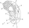
- FIG. 1is a rear perspective view of a self-pivoting TLIF implant in accordance with a first preferred embodiment of the present invention
- FIG. 2is a front perspective view of the self-pivoting TLIF implant of FIG. 1 ;
- FIG. 3is a top plan view of the self-pivoting TLIF implant of FIG. 1 ;
- FIG. 4is a front and left side perspective view of the self-pivoting TLIF implant of FIG. 1 ;
- FIG. 5is a front perspective view of the self-pivoting TLIF implant of FIG. 1 and a bone growth promoting material configured for insertion into the implant;
- FIG. 6is a front perspective view of the self-pivoting TLIF implant of FIG. 1 showing a preferred arrangement of radiopaque markers;
- FIG. 7is a partial front perspective cross-sectional view of an inserter instrument in accordance with a first preferred embodiment of the present invention, the inserter instrument shown in open configuration;
- FIG. 8Ais a top plan view of the inserter instrument of FIG. 7 ;
- FIG. 8Bis a partial front perspective view of the inserter instrument of FIG. 7 in the open configuration
- FIG. 9Ais a top plan view of the inserter instrument of FIG. 7 in an initial articulation position and in a finally locked configuration
- FIG. 9Bis a cross-sectional view of the inserter instrument of FIG. 7 in the initial articulation position and in the finally locked configuration;
- FIG. 9Cis a cross-sectional view of the inserter instrument of FIG. 7 in the initial articulation position and in a provisionally locked configuration
- FIG. 9Dis a cross-sectional view of the inserter instrument of FIG. 7 in a final articulation position and in the provisionally locked configuration;
- FIG. 10Ais a cross-sectional view of the inserter instrument of FIG. 7 in the final articulation position and in the finally locked configuration;
- FIG. 10Bis a top plan view of the inserter instrument of FIG. 7 in the final articulation position and in the finally locked configuration;
- FIG. 10Cis a cross-sectional view of the inserter instrument of FIG. 7 in the final articulation position and in the open configuration;
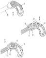
- FIG. 11Ais a top plan view, partially broken away, of one position of the implant of FIG. 1 and the instrument of FIG. 7 with respect to a disc space, partially broken away, as the implant is inserted therein;
- FIG. 11Bis a top plan view, partially broken away, of a the implant and instrument of FIG. 11A in a second position;
- FIG. 11Cis a top plan view, partially broken away, of a the implant and instrument of FIG. 11B in a third position;
- FIG. 11Dis a top plan view of a the implant and instrument of FIG. 11C in a fourth position
- FIG. 12Ais a rear perspective view of a trial implant in accordance with one embodiment of the present invention.
- FIG. 12Bfront perspective view of the trial implant of FIG. 12A ;
- FIG. 12Cis a rear elevational view of the trial implant of FIG. 12A ;
- FIG. 12Dis a left side elevational view of the trial implant of FIG. 12A .
- a TLIF spacer 100is provided that includes an insertion end 110 and an engagement end 115 , the insertion end 110 preferably forming a bullet-nose 112 or having some other tapered geometry for enhancing the ease of insertion and/or for applying a distraction force to the two vertebral bodies between which the implant 100 is configured to be inserted.
- the implant 100further includes a first main or superior surface 120 that is configured for contacting the inferior endplate of a superior vertebral body and a second main or inferior surface 125 that is configured for contacting the superior endplate of an inferior vertebral body.
- One or more walls 130 on anterior and posterior sidesextend between the superior and inferior surfaces 120 , 125 and enclose an axial bore 140 that extends through both the superior and inferior surfaces 120 , 125 .
- the axial bore 140is configured to house a bone graft 190 or other fusion enhancing material.
- One or more lateral windows 150are disposed in the walls 130 and provide a visibility window for observing the fusion occurring between the vertebral bodies and enhancing the vascularization of the bone graft 190 disposed within the axial bore 140 to assist fusion, as well as to increase the volume of the axial bore 140 .
- One or more surface features 145are provided along interior portions of the walls 130 that form the axial bore 140 to assist in securing the bone graft 190 within the axial bore 140 .
- the features 145can assume the form of one or more ridges extending through the axial bore 140 along the cranial-caudal direction, grooves, or other surface texturing that enhances the friction between the bone graft 190 and the interior of the walls 130 that form the axial bore 140 .
- the TLIF spacer 100has a kidney bean or banana shape having a curvilinear geometry between its insertion and engagement ends 110 , 115 . This shape may be accomplished by having an anterior edge of the superior and inferior surfaces 120 , 125 along with the anterior wall 130 be generally concave and a posterior edge of the superior and inferior surfaces 120 , 125 along with the posterior wall 130 be generally convex.
- the implant 100may be utilized for the implant 100 , depending on the desired amount of surface contact between the endplates of the vertebral bodies and the implant 100 , the number of implants 100 desired to be implanted within the disc space (e.g., one or two), the approach chosen for the surgery, the desired location of the implant within the disc space (anterior or posterior), or the like.
- Disposed upon the superior surface 120 adjacent the insertion end 110are a plurality of curvilinear superior ridges 160 that are arranged parallel to one another along the curvature of the TLIF implant 100 .
- the superior ridges 160include two linearly sloped surfaces that meet to form an apex. As the superior ridges 160 extend along their curvilinear path away from the insertion end 110 , the superior ridges 160 are interrupted to form a plurality of superior teeth 162 . The superior teeth 162 are disposed at the engagement end 115 and along at least a portion of anterior and posterior sides of the axial bore 140 . Similarly, disposed upon the inferior surface 125 adjacent the insertion end 110 is a plurality of curvilinear inferior ridges 165 that are arranged parallel to one another along the curvature of the TLIF implant 100 .
- the inferior ridges 165are interrupted to form a plurality of inferior teeth 167 .
- the inferior teeth 167are disposed at the engagement end 115 and on the anterior and posterior sides of the axial bore 140 .
- the superior and inferior ridges 160 , 165guide the insertion of the TLIF implant 100 under the compressive forces of the adjacent vertebral bodies, while the superior and inferior teeth 162 , 167 assist in the primary fixation of the TLIF implant 100 .
- one or more radiopaque markers 170are included in the TLIF implant 100 for enabling visualization and controlling of the position of the TLIF implant 100 during and after insertion into the disc space.
- the markers 170are elongated and include a first marker 170 A, a second marker 170 B, and a third marker 170 C.
- the first and second markers 170 A, 170 Bare disposed in the cranial-caudal direction on either side of the lateral window 150 within the anterior wall 130 of the implant 100 .
- the third marker 170 Cis disposed proximate the insertion end 110 , with a longitudinal axis thereof extending from the insertion end 110 toward the axial bore 140 .
- the engagement end 115is characterized by the absence of the walls 130 extending fully between the superior and inferior surfaces 120 , 125 . That is, a slot 135 is formed at the engagement end 115 that extends continuously between and at least partially along the anterior and posterior walls 130 .
- a post 180is positioned within the slot 135 , which is spaced apart from the anterior and posterior walls 130 and extends at least partially between the superior and inferior surfaces 120 , 125 and serves as an instrument engagement feature. Adequate space is provided by the slot 135 for the engagement portion of an instrument 200 ( FIG. 7 ) to engage the post 180 . As shown in FIGS.
- the walls 130 disposed between the axial bore 140 and the post 180include first and second mating surfaces 132 , 134 facing the post 180 between which an obtuse angle is formed for providing a pair of mechanical stops to the range of allowable articulation of the implant 100 with respect to the instrument 200 .
- the first and second mating surfaces 132 , 134are preferably linear surfaces, but may also be curved or the like. Alternatively, stop pins or the like may be used to limit articulation of the implant 100 .
- the post 180is polygonal in cross-section and includes nine exposed facets 182 a - 182 i arranged around an entire periphery thereof and extending in the cranial-caudal direction between the superior and inferior surfaces 120 , 125 .
- the facets 182 a - 182 iare configured to enhance the engagement and interaction between the instrument 200 and the implant 100 during the insertion of the implant 100 .
- seven of the facets 182 a - 182 f , 182 iare flat surfaces, while the remaining two facets 182 g - 182 h are curved surfaces.
- the post 180may include a different polygonal number of facets 182 .
- the post 180can be cylindrical and thus include zero facets 182 , and may include other features for governing the articulation of the implant 100 with respect to the instrument 200 during its insertion.
- the post 180can include dimples, teeth, surface texturing, grooves, or the like.
- the engagement end 115 of the superior surface 120terminates in a superior corner 122 , which includes superior first and second flat segments 123 , 124 originating near the post 180 and converging at an angle disposed proximate the engagement end 115 of the implant 100 .
- the engagement end 115 of the inferior surface 125terminates in an inferior corner 127 , which include inferior first and second flat segments 128 , 129 originating near the post 180 and converging terminating at an angle disposed proximate the engagement end 115 of the implant 100 .
- the superior first flat segment 123 and the inferior first flat segment 128are configured to be engagable by a portion of the instrument 200 , as is described in detail below, to provide a toggle-free connection, as are the superior second flat segment 124 and the inferior second flat segment 129 .
- the rims of both the superior and inferior corner segments 122 , 127have a width extending a short distance from the superior and inferior surfaces 120 , 125 toward the center of the implant 100 .
- the surfaces of the rimsare also flat for enhancing the interaction between the instrument 200 and the implant 100 .
- the implant 100can be formed from a variety of biocompatible materials, including but not limited to titanium, stainless steel, allograft bone, or polymers such as polyaryletheretherketone (PEEK) and polyetherketoneketone (PEKK), titanfoam, porous PEEK, or the like.
- PEEKpolyaryletheretherketone
- PEKKpolyetherketoneketone
- an instrument 200that includes a longitudinal axis extending between a proximal end 201 and a distal end 202 .
- the instrument 200includes an elongated cannulated outer member 210 that surrounds an elongated inner member 250 .
- the inner member 250is configured to be translatable with respect to the outer member 210 along the longitudinal axis.
- the instrument 200can be configured such that the outer member 210 is translatable with respect to the inner member 250 along the longitudinal axis to perform in the same manner.
- the proximal end of the outer member 210includes a handle portion (not shown) and an actuation mechanism (not shown) for translating the inner member 250 with respect to the outer member 210 .
- the distal end of the outer member 210includes an outer member first arm 220 and an outer member second arm 240 that are separated by a gap 230 that forms the distal portion of the cannula.
- the gap 230includes a pair of laterally-oriented surfaces 232 on either side of the cannula disposed at the proximal end of the outer member first and second arms 220 , 240 .
- the laterally-oriented surfaces 232serve as a stop to the retraction of the inner member 250 with respect to the outer member 210 .
- the interior surface of the first arm 220includes an outer member first arm interior linear taper 222 disposed distal to an outer member first arm interior straight portion 224
- the interior surface of the second arm 240includes an outer member second arm interior linear taper 242 disposed distal to an outer member second arm interior straight portion 244 .
- the first and second arm interior linear tapers 222 , 242combine to form two wedging surfaces.
- a laterally-extending superior exterior flat surface 215 of the outer member 210is disposed between the distal ends of the outer member first and second arms 220 , 240 and the laterally-oriented surfaces 232 .
- a laterally-extending inferior exterior flat surface 216 of the outer member 210is disposed between the distal ends of the outer member first and second arms 220 , 240 and the laterally-oriented surfaces 232 .
- the laterally-extending superior exterior flat surface 215 and the laterally-extending inferior exterior flat surface 216are configured to serve as stops to prevent overarticulation of the implant 100 by abutting the superior and inferior first flat segments 123 , 128 at one end of the articulation range and interacting with the superior and inferior second flat segments 124 , 129 at the other end of the articulation range, as is described in detail below.
- the laterally-extending superior and inferior exterior flat surfaces 215 , 216also abut against the superior and inferior first flat segments 123 , 128 of the implant 100 , or against the superior and inferior second flat segments 124 , 129 of the implant 100 , during a portion of the implant insertion procedure.
- the inner member 250includes at its distal end a grasping portion 255 an inner member first arm 260 and an inner member second arm 280 separated by a split 270 that extends through the middle of the inner member 250 along the longitudinal axis from the grasping portion 255 toward the proximal end.
- the interior surface of the grasping portion 255includes a plurality of engagement surfaces 257 that are configured to complementarily match the polygonal cross sectional geometry of the post 180 of the implant 100 and, thus, engage several of the plurality of facets 182 a - 182 i .
- the exterior surface of the inner member first arm 260includes an inner member first arm exterior linear taper 262 disposed distal to an inner member first arm exterior straight portion 264
- the exterior surface of the inner member second arm 280includes an inner member second arm exterior linear taper 282 disposed distal to an inner member second arm exterior straight portion 284
- Disposed between the inner member first arm exterior linear taper 262 and the distal tip of the inner member first arm 260is an inner member first arm second exterior linear taper 266 .
- an inner member second arm second exterior linear taper 286disposed between the inner member second arm exterior linear taper 282 and the distal tip of the inner member second arm 280 .
- an inner member first arm laterally-oriented flat surface 265 and an inner member second arm laterally-oriented flat surface 285are formed proximal to and adjacent the inner member first arm exterior straight portion 264 and the inner member second arm exterior straight portion 284 , respectively, such that a pair of corners are formed therebetween, and such that the inner member first and second arm laterally-oriented flat surfaces 265 , 285 face and abut with the laterally-oriented surfaces 232 .
- a trial implant 300that includes geometry and surface features identical or similar to the implant 100 and further includes a lateral hole 310 and a longitudinal hole 320 and, therefore, a complete description of the trial implant is omitted for convenience only and is not limiting.
- the trial implant 300is formed from a material that is visible under radiographic imaging, such as titanium, stainless steel, or the like.
- the lateral and longitudinal holes 310 , 320when viewed in conjunction with lateral and frontal X-rays, assist in the optimum positioning of the trial implant 300 .
- the lateral holes 310allow the surgeon to center the trial implant 300 with respect to the spinous processes of the vertebral bodies under fluoroscopy.
- the longitudinal hole 320indicates whether the trial implant 300 has turned, in which case the surgeon will know that more disc material should preferably be removed.
- the lateral and longitudinal holes 310 , 320are shown as being generally circular or cylindrical in the preferred embodiment, but are not so limited.
- the lateral and longitudinal holes 310 , 320may have nearly any size and/or shape, such as rectangular, square, arrow-shaped, and/or triangular that permits visualization of the location of the trial implant 300 under imaging.
- the trial implant 300is not limited to including the lateral and longitudinal holes 310 , 320 or any holes, as location of the trial implant 300 may be visualized via markers or other features that are optically or machine viewable.
- a spinal disc in need of repair or replacementis identified and an at least partial discectomy is performed, preferably via a unilateral transforaminal approach.
- the trial implant 300is inserted and removed using the instrument 200 to gauge the appropriate size implant 100 for insertion into the disc space.
- the insertion and manipulation of the trial implant 300 using the instrument 200is identical to the method of inserting and manipulating the implant 100 using the instrument 200 , as described below.
- the lateral and longitudinal holes 310 , 320are viewed using lateral and/or frontal X-rays to confirm the appropriate position of the trial implant 300 within the disc space and an implant size is then chosen.
- the trial implant 300is used for more than simply measuring the height between the vertebral bodies. Since the trial implant 300 articulates and is inserted to the same desired position as the final implant 100 , the trial implant 300 may be used to determine whether the desired position of the implant 100 is reachable, whether enough disc material has been removed, and the like.
- the bone graft 190is then inserted into the axial bore 140 and secured therein via the surface features 145 (if not already preassembled thereto) and the implant 100 is then coupled to the instrument 200 by distracting the outer member 210 with respect to the inner member 250 via the manipulation of the actuation mechanism (not shown) such that the instrument 200 assumes an open configuration, as seen in FIGS. 7, 8, and 10C .
- the grasping portion 255is then centered around the post 180 and the inner member 250 is partially retracted with respect to the outer member 210 via the manipulation of the actuation mechanism, thereby forcing the pair of corners formed between the inner member first and second arm exterior straight portions 264 , 284 and the inner member first and second arm laterally-oriented flat surfaces 265 , 285 to slidingly bear against the outer member first and second arm interior linear tapers 222 , 242 until the inner member first and second arm exterior straight portions 264 , 284 come to bear against the outer member first and second arm interior straight portions 224 , 244 , while providing the gap 230 between the inner member first and second arm laterally-oriented flat surfaces 265 , 285 and the laterally-oriented surfaces 232 .
- the grasping portion 255is collapsed around the post 180 such that the engagement surfaces 257 a - g come into contact against the plurality of facets 182 a - i of the post 180 and such that the post 180 is provisionally captured by the grasping portion 255 , as shown in FIG. 9C , with the inner member first arm second exterior linear taper 286 bearing against the second linear surface 134 .
- the implant 100is secured to the instrument but the post 180 is capable of rotation with respect to the grasping portion 255 but is prevented from exiting from the grasping portion 255 .
- Final locking of the grasping portion 255 about the post 180as shown in FIGS.
- 9A, 9B, 10A, and 10Bis achieved by fully retracting the inner member 250 with respect to the outer member 210 via the continued manipulation of the actuation mechanism, thereby forcing the outer member first arm interior linear taper 222 and the outer member second arm interior linear taper 242 to come to bear against the inner member first arm exterior linear taper 262 and the inner member second arm exterior linear taper 282 , respectively, thereby closing the gap 230 , and finally locking the implant 100 to the instrument 200 while preventing any portions of the inner member first and second arms 260 , 280 from separating under force from one another across the split 270 due to the contact between the outer member first and second arm interior linear tapers 222 , 242 and the inner member first and second arm exterior linear tapers 262 , 282 .
- the handle portion of the instrument 200is grasped and the insertion end 110 of the implant is inserted into the transforaminal window created during the discectomy procedure until the bullet nose 112 enters the disc space and begins to distract the adjacent vertebral bodies and the distal end of the superior and inferior ridges 160 , 165 make contact with the inferior surface of the superior vertebral body and the superior surface of the inferior vertebral body, respectively.
- Gentle hammer blows or other impaction forcesare administered to the proximal end 201 of the instrument 200 to urge the implant 100 at least partially into the disc space.
- Togglingis prevented between the implant 100 and the instrument 200 during the delivery of impaction forces due to the abutment of ( 1 ) the superior and inferior first flat segments 123 , 128 with the superior and inferior exterior flat surfaces 215 , 216 and/or ( 2 ) the second linear surface 134 with the first arm second linear taper 286 and/or ( 3 ) the plurality of facets 182 a - i of the post 180 with the engagement surface 257 a - f when the instrument 200 is in its finally locked configuration with respect to the implant 100 . Any of these abutments alone or in combination preferably prevent toggling between the implant 100 and the instrument 200 in the finally locked configuration.
- the inner member 250is advanced with respect to the outer member 210 such that the instrument reassumes its provisionally locked configuration with respect to the implant 100 , in which the implant 100 is coupled to the instrument but the post 180 is capable of rotation with respect to the grasping portion 255 .
- the post 180 and, hence, the implant 100rotates with respect to the grasping portion 255 within a range restricted by the stops provided by the interaction between the inner member second arm second exterior linear taper 286 bearing against the second linear surface 134 (the starting configuration of the insertion method) and the inner member first arm second exterior linear taper 266 bearing against the first linear surface 132 (at maximum angulation).
- the angle of the shaft of the instrument 200 with respect to the disc spaceis maintained constant, as all of the action performed to articulate the implant 100 is undertaken by the implant 100 itself as the gentle impaction forces drive the implant 100 into its desired final position guided by the superior and inferior ridges 160 , 165 , with no active turning of the implant necessary.
- the implant 100Upon contact between the inner member first arm second exterior linear taper 266 and the first linear surface 132 , the implant 100 is at or near its desired final positioning interior to the disc space.
- the implant 100can be repositioned as necessary by again finally locking the implant 100 to the instrument 200 , by retracting the inner member 250 distally with respect to the outer member 210 , and manipulating the handle of the instrument 200 until the optimum final positioning of the implant 100 is achieved with respect to the disc space while viewing the position of the markers 170 under fluoroscopic imaging.
- the arrangement of the markers 170enables a single radiographic image, e.g., a lateral image, to be used to determine the precise position of the implant 100 with respect to the disc space.
- the implant 100is then released from the instrument 200 by manipulating the actuation mechanism until the instrument 200 assumes its open configuration, as described previously, and the grasping portion 255 no longer contacts the post 180 .
- the compression forces between the vertebral endplates and the superior and inferior surfaces 120 , 125maintain the implant 100 in place as the instrument 200 is removed from the disc space and the patient's body.
- the insertion and removal of the trial implant 300may cause the formation of grooves in the adjacent endplates of the superior and inferior vertebral bodies due to the inclusion on the superior and inferior surfaces of the trial implant 300 of superior and inferior ridges that are identical to the superior and inferior ridges 160 , 165 of the implant 100 .
- the formation of such grooves in the adjacent endplates of the superior and inferior vertebral bodies, while not required for insertion of the implant 100may assist in easing the insertion of the implant 100 using the instrument 200 via the guided mating of the superior and inferior ridges 160 , 165 with the grooves formed previously by the trial implant 300 .
- an interbody spacerconfigured for insertion via a transforaminal path
- implantsmay be utilized, such as total disc replacements and nucleus replacement devices, by simply configuring such implants to include an appropriately faceted post for an instrument engagement feature and, optionally, the stops and toggle-free bearing surfaces described herein.
- the implant 100is not limited to a banana or kidney bean shape, but may assume any geometry that can be accommodated within the disc space.
- a range of angular approaches to the disc spacemay be utilized where an elongated implant is desired to be manipulated or pivoted once it has been delivered along a straight path into the disc space, such as posterior-lateral approaches, translateral, and direct lateral procedures.
- the non-toggling interface between the implant 100 and the instrument 200 during the delivery of impaction forcesthat is provided by the interaction and abutment of the superior and inferior first flat segments 123 , 128 with the laterally-extending superior and inferior exterior flat surfaces 215 , 216 , as well as the interaction and abutment of the superior and inferior second flat segments 124 , 129 with the laterally-extending superior and inferior exterior flat surfaces 215 , 216 , can also be provided with non-linear abutment surfaces. As long as the surfaces mate or are able to abut one another when the instrument assumes its finally locked configuration, a non-toggling interface can be provided.
- the articulation stops that prevent overarticulation of the implant 100 with respect to the instrument 200that are embodied by the first and second linear surfaces 132 , 134 , and the range of articulation provided by the obtuse angle disposed therebetween, can be provided by a variety of angles which can be tailored specifically to a desired articulation range for a given application, and therefore does not necessarily need to be obtuse.
- the first and second linear surfaces 132 , 134 , as well as the inner member first and second arm second exterior linear tapers 266 , 286 that are abutted thereagainstneed not be linear surfaces.
- any mating abutment surfaceswill suffice between 132 and 266 and between 134 and 286 for the purposes of limiting the articulation range.
- the obtuse angleis removed between the first and second linear surfaces 132 , 134 such that a single abutment surface is provided that can limit the range of articulation by being abuttable by both the first and second arm second exterior linear tapers 266 , 286 and, further, does not need to be linear as long as it provides a mating abutment surface to the geometry chosen for the first and second arm second exterior linear tapers 266 , 286 .
Landscapes
- Health & Medical Sciences (AREA)
- Engineering & Computer Science (AREA)
- Biomedical Technology (AREA)
- Orthopedic Medicine & Surgery (AREA)
- Transplantation (AREA)
- Neurology (AREA)
- Heart & Thoracic Surgery (AREA)
- Oral & Maxillofacial Surgery (AREA)
- Cardiology (AREA)
- Vascular Medicine (AREA)
- Life Sciences & Earth Sciences (AREA)
- Animal Behavior & Ethology (AREA)
- General Health & Medical Sciences (AREA)
- Public Health (AREA)
- Veterinary Medicine (AREA)
- Physical Education & Sports Medicine (AREA)
- Prostheses (AREA)
Abstract
Description
The present application is a continuation of U.S. application Ser. No. 15/863,109, filed Jan. 5, 2018, which is a continuation of U.S. application Ser. No. 15/161,562, filed May 23, 2016 now U.S. Pat. No. 9,931,224, which is a divisional of U.S. application Ser. No. 14/505,471, filed Oct. 2, 2014 now U.S. Pat. No. 9,358,133, which is a divisional of U.S. application Ser. No. 12/612,886, filed Nov. 5, 2009 now U.S. Pat. No. 9,028,553, the entire contents of each of which are incorporated by reference into this application.
The unilateral transforaminal insertion of an interbody spacer for lumbar spinal fusion presents challenges to the surgeon tasked with the procedure due to the curved manipulation path that the implant must undergo once it enters the disc space. The procedure presents a further challenge of coupling the implant to the inserter instrument while allowing the implant a limited amount of rotation or articulation to follow the desired path. These challenges also present themselves to other angular unilateral approaches to the spine, in which the initial access corridor is linear yet, once the implant enters the disc space, the implant must be manipulated or articulated along a curved path. Conventional transforaminal lateral interbody fusion
(TLIF) implants, for example, are inserted using a combination of a linear insertion path and a hammering of the implant into the desired position using pushers that provide the desired anterior positioning of the implant. Alternately, a stepwise straight hammering process alternating with an active turning technique is often used to manipulate the implant from the entry position to the final desired position. The conventional TLIF and other angular unilateral systems and insertion methods fail to provide implants, instrumentation, and methods that allow the implant to be easily inserted to its final desired position within the disc space.
It is therefore desired to provide a spinal implant and associated instrument and method that improves the ease with which the implant may be manipulated during insertion or once within the disc space.
Briefly stated, a first embodiment of the present invention comprises an intervertebral implant including an insertion end, an opposing engagement end, and first and second opposed main surfaces configured to contact respective adjacent vertebral endplates. Each of the first and second main surfaces has an anterior edge, a posterior edge, and extends between the insertion and engagement ends. An anterior wall is formed between the first and second main surfaces and along the anterior edges thereof. A posterior wall is formed between the first and second main surfaces and along the posterior edges thereof. The anterior wall and the posterior wall converge at the insertion and engagement ends. A slot is formed at the engagement end and extends continuously between and at least partially along the anterior and posterior walls. A post is positioned within the slot, spaced from at least one of the anterior and posterior walls and extending at least partially between the first and second main surfaces. The post includes a plurality of exposed facets and is configured for engagement with a pivotable insertion instrument.
Another embodiment of the present invention comprises an intervertebral implant including an insertion end, an opposing engagement end, and first and second opposed main surfaces configured to contact respective adjacent vertebral endplates. Each of the first and second main surfaces has an anterior edge, a posterior edge, and extends between the insertion and engagement ends. Each anterior edge has a generally linear portion proximate the engagement end and a generally concave portion, and each posterior edge has a generally linear portion proximate the engagement end and a generally convex portion. The generally linear portion of the anterior edge converges with the generally linear portion of the posterior edge at the engagement end for each of the first and second main surfaces. An anterior wall is formed between the first and second main surfaces and along the anterior edges thereof. A posterior wall is formed between the first and second main surfaces and along the posterior edges thereof. The anterior wall and the posterior wall converge at the insertion and engagement ends. A slot is formed at the engagement end and extends continuously between and at least partially along the anterior and posterior walls. A post is positioned within the slot, spaced from at least one of the anterior and posterior walls and extending at least partially between the first and second main surfaces. The post includes a plurality of exposed facets and is configured for engagement with a pivotable insertion instrument.
Still another embodiment of the present invention comprises an intervertebral implant including an insertion end, an opposing engagement end, and first and second opposed main surfaces configured to contact respective adjacent vertebral endplates. Each of the first and second main surfaces has an anterior edge, a posterior edge, and extends between the insertion and engagement ends. Each anterior edge is generally concave and each posterior edge is generally convex. An anterior wall is formed between the first and second main surfaces and along the anterior edges thereof. A posterior wall is formed between the first and second main surfaces and along the posterior edges thereof. The anterior wall and the posterior wall converge at the insertion and engagement ends. A slot is formed at the engagement end and extends continuously between and at least partially along the anterior and posterior walls. A post is positioned within the slot, spaced from the anterior and posterior walls and extending at least partially between the first and second main surfaces. The post includes a plurality of facets disposed around an entire periphery thereof and is configured for engagement with a pivotable insertion instrument. At least one abutment surface is disposed within the slot distally from the post. The at least one abutment surface limits rotation of the implant about the post when the post is engaged with the pivotable insertion instrument.
Yet another embodiment of the present invention comprises an intervertebral implant including an insertion end, an opposing engagement end, and first and second opposed main surfaces configured to contact respective adjacent vertebral endplates. Each of the first and second main surfaces has an anterior edge, a posterior edge, and extends between the insertion and engagement ends. Each anterior edge is generally concave and each posterior edge is generally convex. An axial bore is formed between the anterior and posterior edges and extends between the first and second main surfaces. An anterior wall is formed between the first and second main surfaces and along the anterior edges thereof. A posterior wall is formed between the first and second main surfaces and along the posterior edges thereof. The anterior wall and the posterior wall converge at the insertion and engagement ends. A slot is formed at the engagement end and extends at least partially along the anterior and posterior walls. A post is positioned within the slot and extends at least partially between the first and second main surfaces. The post includes a plurality of facets and is configured for engagement with a pivotable insertion instrument. The intervertebral implant also includes a plurality of markers. At least one of the markers extends between the first and second main surfaces within one of the anterior and posterior walls. At least one other of the markers is disposed generally transverse to the at least one of the markers and extends from the insertion end toward the axial bore.
A still further embodiment of the present invention comprises a method for implanting an intervertebral implant into a disc space disposed between first and second endplates of adjacent vertebral bodies of a patient. The method includes providing an access corridor to a spinal level in need, removing at least a portion of disc material between the adjacent vertebra, and providing an interbody spacer implant. The implant includes an insertion end, an opposing engagement end, and first and second opposed main surfaces configured to contact the respective first and second vertebral endplates. Each of the first and second main surfaces has an anterior edge, a posterior edge, and extends between the insertion and engagement ends. Each anterior edge is generally concave and each posterior edge is generally convex. Each of the first and second main surfaces includes a plurality of curved parallel ridges protruding from the respective surface and extending from the insertion end to the engagement end. Each of the plurality of parallel ridges includes a plurality of teeth. An anterior wall is formed between the first and second main surfaces and along the anterior edges thereof. A posterior wall is formed between the first and second main surfaces and along the posterior edges thereof. The anterior wall and the posterior wall converge at the insertion and engagement ends. A slot is formed at the engagement end and extends continuously between and at least partially along the anterior and posterior walls. A post is positioned within the slot, spaced from at least one of the anterior and posterior walls and extending at least partially between the first and second main surfaces. The post includes a plurality of exposed facets and is configured for engagement with a pivotable insertion instrument. The method also includes providing an insertion instrument. The instrument includes a proximal end, a distal end, and a longitudinal axis therebetween, and an inner member and an outer member. The inner member is movable along the longitudinal axis with respect to the outer member. The inner member has a grasping portion at the distal end. The grasping portion includes a plurality of facet surfaces configured for engagement with the plurality of the post facets. The method also includes inserting the grasping portion of the instrument into the slot of the implant such that the grasping portion surrounds the post, engaging the post of the implant with the grasping portion of the instrument such that the post is rotationally fixed with respect to the grasping portion, inserting the implant using the instrument through the access corridor until at least the insertion end is introduced into the at least partially cleared out disc space and such that the at least a portion of the ridges of the first and second main surfaces contact the first and second verebtral endplates, respectively, adjusting the instrument such that the post of the implant remains engaged with the grasping portion of the instrument but rotation of the post is permitted within the grasping portion, delivering impaction forces to the proximal end of the instrument such that the post of the implant articulates with respect to the grasping portion of the instrument and the implant is guided by vertebral rails into a desired position, releasing the post of the implant from the grasping portion of the instrument, and withdrawing the instrument through the access corridor.
Yet another embodiment of the present invention comprises a system for spine surgery at a disc space disposed between first and second endplates of adjacent vertebral bodies of a patient. The system includes an intervertebral implant including an insertion end and an opposing engagement end. First and second opposed main surfaces are configured to contact respective adjacent vertebral endplates. Each of the first and second main surfaces has an anterior edge, a posterior edge, and extends between the insertion and engagement ends. An anterior wall is formed between the first and second main surfaces and along the anterior edges thereof. A posterior wall is formed between the first and second main surfaces and along the posterior edges thereof. The anterior wall and the posterior wall converge at the insertion and engagement ends. A slot is formed at the engagement end and extends continuously between and at least partially along the anterior and posterior walls. A post is positioned within the slot, spaced from at least one of the anterior and posterior walls and extending at least partially between the first and second main surfaces. The post includes a plurality of exposed facets. A trial implant includes an insertion end and an opposing engagement end. First and second opposed main surfaces are configured to contact respective adjacent vertebral endplates. Each of the first and second main surfaces has an anterior edge, a posterior edge, and extends between the insertion and engagement ends. An anterior wall is formed between the first and second main surfaces and along the anterior edges thereof. A posterior wall is formed between the first and second main surfaces and along the posterior edges thereof. The anterior wall and the posterior wall converge at the insertion and engagement ends. A slot is formed at the engagement end and extends continuously between and at least partially along the anterior and posterior walls. A post is positioned within the slot, spaced from at least one of the anterior and posterior walls and extending at least partially between the first and second main surfaces. The post includes a plurality of exposed facets. An insertion instrument includes a proximal end, a distal end, a longitudinal axis therebetween, an inner member, and an outer member. The inner member is translatable with respect to the outer member along the longitudinal axis and has a grasping portion at the distal end. The grasping portion includes a plurality of facet surfaces engagable with the plurality of the post facets of the intervertebral implant and the trial implant. The instrument has a first configuration in which the grasping portion assumes an open configuration for allowing coupling of the instrument to the post of one of the intervertebral implant and the trial implant, a second configuration in which the instrument is securely coupled to the post of one of the intervertebral implant and the trial implant while allowing the post to rotate within the grasping portion under a given force, and a third configuration wherein the instrument is securely coupled to the post of one of the intervertebral implant and the trial implant while preventing rotation of the post with respect to the grasping portion.
The foregoing summary, as well as the following detailed description of preferred embodiments of the instrument of the present application, will be better understood when read in conjunction with the appended drawings. For the purposes of illustrating the self-pivoting spinal implant and the associated instrumentation of the present application, there is shown in the drawings preferred embodiments. It should be understood, however, that the application is not limited to the precise arrangements and instrumentalities shown. In the drawings:
Certain terminology is used in the following description for convenience only and is not limiting. The words “right,” “left,” “lower,” and “upper” designate directions in the drawings to which reference is made. The words “inwardly” or “distally” and “outwardly” or “proximally” refer to directions toward and away from, respectively, the patient's body, or the geometric center of the interbody spacer implant and related parts thereof. The words, “anterior,” “posterior,” “superior,” “inferior,” and related words and/or phrases designate preferred positions and orientations in the human body to which reference is made and are not meant to be limiting. The terminology includes the above-listed words, derivatives thereof and words of similar import.
Referring toFIGS. 1-6 , aTLIF spacer 100 is provided that includes aninsertion end 110 and anengagement end 115, theinsertion end 110 preferably forming a bullet-nose 112 or having some other tapered geometry for enhancing the ease of insertion and/or for applying a distraction force to the two vertebral bodies between which theimplant 100 is configured to be inserted. Theimplant 100 further includes a first main orsuperior surface 120 that is configured for contacting the inferior endplate of a superior vertebral body and a second main orinferior surface 125 that is configured for contacting the superior endplate of an inferior vertebral body. One ormore walls 130 on anterior and posterior sides extend between the superior andinferior surfaces axial bore 140 that extends through both the superior andinferior surfaces axial bore 140 is configured to house abone graft 190 or other fusion enhancing material.
One or morelateral windows 150 are disposed in thewalls 130 and provide a visibility window for observing the fusion occurring between the vertebral bodies and enhancing the vascularization of thebone graft 190 disposed within theaxial bore 140 to assist fusion, as well as to increase the volume of theaxial bore 140. One or more surface features145 are provided along interior portions of thewalls 130 that form theaxial bore 140 to assist in securing thebone graft 190 within theaxial bore 140. Thefeatures 145 can assume the form of one or more ridges extending through theaxial bore 140 along the cranial-caudal direction, grooves, or other surface texturing that enhances the friction between thebone graft 190 and the interior of thewalls 130 that form theaxial bore 140.
In a first preferred embodiment, theTLIF spacer 100 has a kidney bean or banana shape having a curvilinear geometry between its insertion and engagement ends110,115. This shape may be accomplished by having an anterior edge of the superior andinferior surfaces anterior wall 130 be generally concave and a posterior edge of the superior andinferior surfaces posterior wall 130 be generally convex. However, a variety of geometries may be utilized for theimplant 100, depending on the desired amount of surface contact between the endplates of the vertebral bodies and theimplant 100, the number ofimplants 100 desired to be implanted within the disc space (e.g., one or two), the approach chosen for the surgery, the desired location of the implant within the disc space (anterior or posterior), or the like. Disposed upon thesuperior surface 120 adjacent theinsertion end 110 are a plurality of curvilinearsuperior ridges 160 that are arranged parallel to one another along the curvature of theTLIF implant 100.
In a first preferred embodiment, thesuperior ridges 160 include two linearly sloped surfaces that meet to form an apex. As thesuperior ridges 160 extend along their curvilinear path away from theinsertion end 110, thesuperior ridges 160 are interrupted to form a plurality ofsuperior teeth 162. Thesuperior teeth 162 are disposed at theengagement end 115 and along at least a portion of anterior and posterior sides of theaxial bore 140. Similarly, disposed upon theinferior surface 125 adjacent theinsertion end 110 is a plurality of curvilinearinferior ridges 165 that are arranged parallel to one another along the curvature of theTLIF implant 100. As theinferior ridges 165 extend along their curvilinear path away from theinsertion end 110, theinferior ridges 165 are interrupted to form a plurality ofinferior teeth 167. Theinferior teeth 167 are disposed at theengagement end 115 and on the anterior and posterior sides of theaxial bore 140. The superior andinferior ridges TLIF implant 100 under the compressive forces of the adjacent vertebral bodies, while the superior andinferior teeth TLIF implant 100.
Referring toFIGS. 3, 4, and 6 , one or moreradiopaque markers 170, made from material capable of radiographical imaging, such as pins or beads of stainless steel, titanium, tantalum, titanium-aluminum-niobium (TAN), or the like, are included in theTLIF implant 100 for enabling visualization and controlling of the position of theTLIF implant 100 during and after insertion into the disc space. In a first preferred embodiment, themarkers 170 are elongated and include a first marker170A, a second marker170B, and a third marker170C. The first and second markers170A,170B are disposed in the cranial-caudal direction on either side of thelateral window 150 within theanterior wall 130 of theimplant 100. The third marker170C is disposed proximate theinsertion end 110, with a longitudinal axis thereof extending from theinsertion end 110 toward theaxial bore 140.
Theengagement end 115 is characterized by the absence of thewalls 130 extending fully between the superior andinferior surfaces slot 135 is formed at theengagement end 115 that extends continuously between and at least partially along the anterior andposterior walls 130. Apost 180 is positioned within theslot 135, which is spaced apart from the anterior andposterior walls 130 and extends at least partially between the superior andinferior surfaces slot 135 for the engagement portion of an instrument200 (FIG. 7 ) to engage thepost 180. As shown inFIGS. 9 and 10 , within theimplant 100, thewalls 130 disposed between theaxial bore 140 and thepost 180 include first and second mating surfaces132,134 facing thepost 180 between which an obtuse angle is formed for providing a pair of mechanical stops to the range of allowable articulation of theimplant 100 with respect to theinstrument 200. The first and second mating surfaces132,134 are preferably linear surfaces, but may also be curved or the like. Alternatively, stop pins or the like may be used to limit articulation of theimplant 100.
Referring now toFIGS. 9 and 10 , in a first preferred embodiment, thepost 180 is polygonal in cross-section and includes nine exposed facets182a-182iarranged around an entire periphery thereof and extending in the cranial-caudal direction between the superior andinferior surfaces instrument 200 and theimplant 100 during the insertion of theimplant 100. Preferably, seven of the facets182a-182f,182iare flat surfaces, while the remaining twofacets 182g-182hare curved surfaces. In an alternate embodiment, thepost 180 may include a different polygonal number of facets182. In yet another alternate embodiment, thepost 180 can be cylindrical and thus include zero facets182, and may include other features for governing the articulation of theimplant 100 with respect to theinstrument 200 during its insertion. For example, thepost 180 can include dimples, teeth, surface texturing, grooves, or the like.
Referring now toFIGS. 1-5 and 7 , theengagement end 115 of thesuperior surface 120 terminates in asuperior corner 122, which includes superior first and secondflat segments post 180 and converging at an angle disposed proximate theengagement end 115 of theimplant 100. Similarly, theengagement end 115 of theinferior surface 125 terminates in aninferior corner 127, which include inferior first and secondflat segments post 180 and converging terminating at an angle disposed proximate theengagement end 115 of theimplant 100. The superior firstflat segment 123 and the inferior firstflat segment 128 are configured to be engagable by a portion of theinstrument 200, as is described in detail below, to provide a toggle-free connection, as are the superior secondflat segment 124 and the inferior secondflat segment 129. The rims of both the superior andinferior corner segments inferior surfaces implant 100. The surfaces of the rims are also flat for enhancing the interaction between theinstrument 200 and theimplant 100. Theimplant 100 can be formed from a variety of biocompatible materials, including but not limited to titanium, stainless steel, allograft bone, or polymers such as polyaryletheretherketone (PEEK) and polyetherketoneketone (PEKK), titanfoam, porous PEEK, or the like.
Referring toFIGS. 7-8 , aninstrument 200 is provided that includes a longitudinal axis extending between aproximal end 201 and adistal end 202. Theinstrument 200 includes an elongated cannulatedouter member 210 that surrounds an elongatedinner member 250. Theinner member 250 is configured to be translatable with respect to theouter member 210 along the longitudinal axis. Alternatively, theinstrument 200 can be configured such that theouter member 210 is translatable with respect to theinner member 250 along the longitudinal axis to perform in the same manner. The proximal end of theouter member 210 includes a handle portion (not shown) and an actuation mechanism (not shown) for translating theinner member 250 with respect to theouter member 210. The distal end of theouter member 210 includes an outer memberfirst arm 220 and an outer membersecond arm 240 that are separated by agap 230 that forms the distal portion of the cannula. Thegap 230 includes a pair of laterally-orientedsurfaces 232 on either side of the cannula disposed at the proximal end of the outer member first andsecond arms surfaces 232 serve as a stop to the retraction of theinner member 250 with respect to theouter member 210. The interior surface of thefirst arm 220 includes an outer member first arm interiorlinear taper 222 disposed distal to an outer member first arm interiorstraight portion 224, while the interior surface of thesecond arm 240 includes an outer member second arm interiorlinear taper 242 disposed distal to an outer member second arm interiorstraight portion 244. The first and second arm interiorlinear tapers
A laterally-extending superior exteriorflat surface 215 of theouter member 210 is disposed between the distal ends of the outer member first andsecond arms surfaces 232. Similarly, a laterally-extending inferior exteriorflat surface 216 of theouter member 210 is disposed between the distal ends of the outer member first andsecond arms surfaces 232. The laterally-extending superior exteriorflat surface 215 and the laterally-extending inferior exteriorflat surface 216 are configured to serve as stops to prevent overarticulation of theimplant 100 by abutting the superior and inferior firstflat segments flat segments flat surfaces flat segments implant 100, or against the superior and inferior secondflat segments implant 100, during a portion of the implant insertion procedure.
Theinner member 250 includes at its distal end a graspingportion 255 an inner memberfirst arm 260 and an inner membersecond arm 280 separated by asplit 270 that extends through the middle of theinner member 250 along the longitudinal axis from the graspingportion 255 toward the proximal end. The interior surface of the graspingportion 255 includes a plurality of engagement surfaces257 that are configured to complementarily match the polygonal cross sectional geometry of thepost 180 of theimplant 100 and, thus, engage several of the plurality of facets182a-182i. In a first preferred embodiment, there are seven engagement surfaces257a-257gthat are configured to engage seven of the nine facets182a-182iof thepost 180. Configured to interact with the interior surfaces of the outer member first andsecond arms first arm 260 includes an inner member first arm exteriorlinear taper 262 disposed distal to an inner member first arm exteriorstraight portion 264, while the exterior surface of the inner membersecond arm 280 includes an inner member second arm exteriorlinear taper 282 disposed distal to an inner member second arm exteriorstraight portion 284. Disposed between the inner member first arm exteriorlinear taper 262 and the distal tip of the inner memberfirst arm 260 is an inner member first arm second exteriorlinear taper 266.
Similarly, disposed between the inner member second arm exteriorlinear taper 282 and the distal tip of the inner membersecond arm 280 is an inner member second arm second exteriorlinear taper 286. Further, an inner member first arm laterally-orientedflat surface 265 and an inner member second arm laterally-orientedflat surface 285 are formed proximal to and adjacent the inner member first arm exteriorstraight portion 264 and the inner member second arm exteriorstraight portion 284, respectively, such that a pair of corners are formed therebetween, and such that the inner member first and second arm laterally-orientedflat surfaces surfaces 232.
Referring toFIG. 12 , atrial implant 300 is provided that includes geometry and surface features identical or similar to theimplant 100 and further includes alateral hole 310 and alongitudinal hole 320 and, therefore, a complete description of the trial implant is omitted for convenience only and is not limiting. Thetrial implant 300 is formed from a material that is visible under radiographic imaging, such as titanium, stainless steel, or the like. The lateral andlongitudinal holes trial implant 300. The lateral holes310 allow the surgeon to center thetrial implant 300 with respect to the spinous processes of the vertebral bodies under fluoroscopy. Thelongitudinal hole 320 indicates whether thetrial implant 300 has turned, in which case the surgeon will know that more disc material should preferably be removed. The lateral andlongitudinal holes longitudinal holes trial implant 300 under imaging. In addition, thetrial implant 300 is not limited to including the lateral andlongitudinal holes trial implant 300 may be visualized via markers or other features that are optically or machine viewable.
In operation, and in continuing reference toFIGS. 1-12 , a spinal disc in need of repair or replacement is identified and an at least partial discectomy is performed, preferably via a unilateral transforaminal approach. Thetrial implant 300 is inserted and removed using theinstrument 200 to gauge theappropriate size implant 100 for insertion into the disc space. The insertion and manipulation of thetrial implant 300 using theinstrument 200 is identical to the method of inserting and manipulating theimplant 100 using theinstrument 200, as described below. The lateral andlongitudinal holes trial implant 300 within the disc space and an implant size is then chosen.
Thus, thetrial implant 300 is used for more than simply measuring the height between the vertebral bodies. Since thetrial implant 300 articulates and is inserted to the same desired position as thefinal implant 100, thetrial implant 300 may be used to determine whether the desired position of theimplant 100 is reachable, whether enough disc material has been removed, and the like.
Thebone graft 190 is then inserted into theaxial bore 140 and secured therein via the surface features145 (if not already preassembled thereto) and theimplant 100 is then coupled to theinstrument 200 by distracting theouter member 210 with respect to theinner member 250 via the manipulation of the actuation mechanism (not shown) such that theinstrument 200 assumes an open configuration, as seen inFIGS. 7, 8, and 10C . The graspingportion 255 is then centered around thepost 180 and theinner member 250 is partially retracted with respect to theouter member 210 via the manipulation of the actuation mechanism, thereby forcing the pair of corners formed between the inner member first and second arm exteriorstraight portions flat surfaces linear tapers straight portions straight portions gap 230 between the inner member first and second arm laterally-orientedflat surfaces surfaces 232. Consequently, the graspingportion 255 is collapsed around thepost 180 such that the engagement surfaces257a-gcome into contact against the plurality of facets182a-iof thepost 180 and such that thepost 180 is provisionally captured by the graspingportion 255, as shown inFIG. 9C , with the inner member first arm second exteriorlinear taper 286 bearing against the secondlinear surface 134.
In this provisionally locked configuration, theimplant 100 is secured to the instrument but thepost 180 is capable of rotation with respect to the graspingportion 255 but is prevented from exiting from the graspingportion 255. Final locking of the graspingportion 255 about thepost 180, as shown inFIGS. 9A, 9B, 10A, and 10B , is achieved by fully retracting theinner member 250 with respect to theouter member 210 via the continued manipulation of the actuation mechanism, thereby forcing the outer member first arm interiorlinear taper 222 and the outer member second arm interiorlinear taper 242 to come to bear against the inner member first arm exteriorlinear taper 262 and the inner member second arm exteriorlinear taper 282, respectively, thereby closing thegap 230, and finally locking theimplant 100 to theinstrument 200 while preventing any portions of the inner member first andsecond arms split 270 due to the contact between the outer member first and second arm interiorlinear tapers linear tapers flat surfaces flat segments gap 230 is closed, the inner member first arm second exteriorlinear taper 286 still bears against the secondlinear surface 134, and thepost 180 is incapable of rotating with respect to the graspingportion 255.
In the finally locked configuration, the handle portion of theinstrument 200 is grasped and theinsertion end 110 of the implant is inserted into the transforaminal window created during the discectomy procedure until thebullet nose 112 enters the disc space and begins to distract the adjacent vertebral bodies and the distal end of the superior andinferior ridges proximal end 201 of theinstrument 200 to urge theimplant 100 at least partially into the disc space. Toggling is prevented between theimplant 100 and theinstrument 200 during the delivery of impaction forces due to the abutment of (1) the superior and inferior firstflat segments flat surfaces linear surface 134 with the first arm secondlinear taper 286 and/or (3) the plurality of facets182a-iof thepost 180 with the engagement surface257a-fwhen theinstrument 200 is in its finally locked configuration with respect to theimplant 100. Any of these abutments alone or in combination preferably prevent toggling between theimplant 100 and theinstrument 200 in the finally locked configuration.
Once the impaction forces drive theimplant 100 along a linear path to a desired position within the disc space, as seen inFIG. 11A , with theinstrument 200 finally locked to theimplant 100, theinner member 250 is advanced with respect to theouter member 210 such that the instrument reassumes its provisionally locked configuration with respect to theimplant 100, in which theimplant 100 is coupled to the instrument but thepost 180 is capable of rotation with respect to the graspingportion 255. At this point, additional gentle hammer blows or other impaction forces are administered to the proximal end of theinstrument 200 and the superior andinferior ridges implant 100 and guide the path of insertion of theimplant 100 as theinsertion end 110 progresses into the disc space. As the superior andinferior ridges implant 100 into the desired position within the disc space, thepost 180 and, hence, theimplant 100, rotates with respect to the graspingportion 255 within a range restricted by the stops provided by the interaction between the inner member second arm second exteriorlinear taper 286 bearing against the second linear surface134 (the starting configuration of the insertion method) and the inner member first arm second exteriorlinear taper 266 bearing against the first linear surface132 (at maximum angulation).
Throughout the entirety of the insertion process, the angle of the shaft of theinstrument 200 with respect to the disc space is maintained constant, as all of the action performed to articulate theimplant 100 is undertaken by theimplant 100 itself as the gentle impaction forces drive theimplant 100 into its desired final position guided by the superior andinferior ridges linear taper 266 and the firstlinear surface 132, theimplant 100 is at or near its desired final positioning interior to the disc space. At this point, theimplant 100 can be repositioned as necessary by again finally locking theimplant 100 to theinstrument 200, by retracting theinner member 250 distally with respect to theouter member 210, and manipulating the handle of theinstrument 200 until the optimum final positioning of theimplant 100 is achieved with respect to the disc space while viewing the position of themarkers 170 under fluoroscopic imaging. The arrangement of themarkers 170 enables a single radiographic image, e.g., a lateral image, to be used to determine the precise position of theimplant 100 with respect to the disc space. Theimplant 100 is then released from theinstrument 200 by manipulating the actuation mechanism until theinstrument 200 assumes its open configuration, as described previously, and the graspingportion 255 no longer contacts thepost 180. The compression forces between the vertebral endplates and the superior andinferior surfaces implant 100 in place as theinstrument 200 is removed from the disc space and the patient's body.
The insertion and removal of thetrial implant 300 may cause the formation of grooves in the adjacent endplates of the superior and inferior vertebral bodies due to the inclusion on the superior and inferior surfaces of thetrial implant 300 of superior and inferior ridges that are identical to the superior andinferior ridges implant 100. The formation of such grooves in the adjacent endplates of the superior and inferior vertebral bodies, while not required for insertion of theimplant 100, may assist in easing the insertion of theimplant 100 using theinstrument 200 via the guided mating of the superior andinferior ridges trial implant 300.
While embodiments of the present invention are described herein with respect to an interbody spacer configured for insertion via a transforaminal path, a variety of implants may be utilized, such as total disc replacements and nucleus replacement devices, by simply configuring such implants to include an appropriately faceted post for an instrument engagement feature and, optionally, the stops and toggle-free bearing surfaces described herein. As such, theimplant 100 is not limited to a banana or kidney bean shape, but may assume any geometry that can be accommodated within the disc space. Further, a range of angular approaches to the disc space may be utilized where an elongated implant is desired to be manipulated or pivoted once it has been delivered along a straight path into the disc space, such as posterior-lateral approaches, translateral, and direct lateral procedures.
In an alternate embodiment, the non-toggling interface between theimplant 100 and theinstrument 200 during the delivery of impaction forces that is provided by the interaction and abutment of the superior and inferior firstflat segments flat surfaces flat segments flat surfaces
Similarly, the articulation stops that prevent overarticulation of theimplant 100 with respect to theinstrument 200 that are embodied by the first and secondlinear surfaces linear surfaces linear tapers linear surfaces linear tapers linear tapers
It will be appreciated by those skilled in the art that changes could be made to the embodiments described above without departing from the broad inventive concept thereof. It is understood, therefore, that this invention is not limited to the particular embodiments disclosed, but it is intended to cover modifications within the spirit and scope of the present invention as defined by the present description.
Claims (19)
1. A method of spinal surgery, comprising:
grasping a post of an intervertebral implant with a grasper at a distal end of an instrument, wherein the post is disposed within a slot at an engagement end of the intervertebral implant;
advancing the intervertebral implant toward an intervertebral disc space of a patient while maintaining the intervertebral implant in an initial articulation position, in which a surface of the grasper abuts a surface of the intervertebral implant in a manner preventing articulation of the intervertebral implant beyond a range of articulation relative to the instrument;
inserting the intervertebral implant into the intervertebral disc space; and
during the inserting step, rotating the post with respect to the grasper, thereby rotating the intervertebral implant with respect to the instrument from the initial articulation position to a final articulation position, in which another surface of the grasper abuts another surface of the intervertebral implant in a manner preventing articulation of the intervertebral implant beyond the range of articulation, wherein the surface and the another surface of the intervertebral implant are angularly offset from each other.
2. The method ofclaim 1 , wherein the grasping step comprises at least partially surrounding the post with a first distal tip of a first arm of the grasper and a second distal tip of a second arm of the grasper, wherein the first and second distal tips converge toward each other.
3. The method ofclaim 2 , wherein the grasping step further comprises moving the grasper from a first position to a second position, thereby reducing a distance between interior surfaces of the first and second arms.
4. The method ofclaim 3 , wherein:
the grasper extends from an inner member received within a cannulated outer member of the instrument;
the first and second arms are resiliently coupled to each other and biased away from each other; and
moving the grasper from the first position to the second position comprises moving the cannulated outer member in a distal direction relative to the grasper, wherein the distal direction extends from a proximal end of the instrument to the distal end.
5. The method ofclaim 4 , wherein:
the interior surfaces of the first and second arms each define a plurality of arm engagement surfaces,
the post defines an exterior surface having a plurality of post engagement surfaces, and
moving the grasper from the first position to the second position comprises bringing the arm engagement surfaces into engagement with the post engagement surfaces in a manner preventing rotation of the post with respect to the grasper.
6. The method ofclaim 5 , further comprising, after the grasping step and prior to rotating the post with respect to the grasper, moving the cannulated outer member relative to the grasper in a proximal direction opposite the distal direction, thereby increasing the distance between the interior surfaces of the first and second arms and disengaging the arm engagement surfaces from the post engagement surfaces.
7. The method ofclaim 2 , wherein the distal end of the instrument is spaced from a proximal end of the instrument in a distal direction, the first arm defines the surface of the grasper, the second arm defines the another surface of the grasper, and the surface and the another surface of the grasper converge toward each other with respect to the distal direction.
8. The method ofclaim 7 , wherein the surface and the another surface of the grasper are each linear, and the surface and the another surface of the intervertebral implant are each linear.
9. The method ofclaim 8 , wherein the surface and the another surface of the intervertebral implant are angularly offset from one another at an obtuse angle.
10. The method ofclaim 7 , wherein the surface and the another surface of the intervertebral implant are each remote from the post and each faces the post.
11. The method ofclaim 1 , wherein:
the surface of the instrument is a first stop surface;
the surface and the another surface of the intervertebral implant are respective second and third stop surfaces located at the engagement end and angularly offset from one another; and
rotating the intervertebral implant with respect to the instrument comprises moving the second stop surface away from the first stop surface while moving the third stop surface toward the first stop surface.
12. The method ofclaim 11 , wherein:
the instrument is elongate along a longitudinal direction extending between a proximal end of the instrument to the distal ends, the instrument further defining a fourth stop surface spaced from the first stop surface along a second direction perpendicular to the longitudinal direction;
the intervertebral implant defines a fifth stop surface and a sixth stop surface at the engagement end, the fifth and sixth stop surfaces angularly offset from one another, the second and fifth stop surfaces located on opposite sides of the slot with respect to the second direction, the third and sixth stop surfaces located on opposite sides of the slot with respect to the second direction; and
rotating the intervertebral implant with respect to the instrument further comprises moving the fifth stop surface away from the fourth stop surface while moving the sixth stop surface toward the fourth stop surface.
13. The method ofclaim 12 , wherein the first and fourth stop surfaces are each oriented along a transverse direction that is perpendicular to the longitudinal and second directions.
14. The method ofclaim 1 , wherein the inserting step comprises delivering impaction forces to the instrument, and the impaction forces cause the rotation of the post with respect to the grasper.
15. The method ofclaim 14 , wherein the inserting step further comprises contacting superior and inferior opposed main surfaces of the intervertebral implant against first and second opposed endplates of adjacent first and second vertebrae, wherein the intervertebral space is defined between the first and second opposed endplates, and the super and inferior opposed main surfaces extend between the engagement end to an insertion end of the intervertebral implant opposite the engagement end.
16. The method ofclaim 15 , wherein the contacting step further comprises engaging a plurality of curvilinear ridges disposed on one or both of the superior and inferior opposed main surfaces of the intervertebral implant respectively against one or both of the first and second opposed endplates, such that the step of delivering impaction forces promotes rotating the intervertebral implant with respect to the instrument.
17. The method ofclaim 16 , wherein the superior and inferior opposed main surfaces extend from an anterior side of the intervertebral implant to a posterior side of the intervertebral implant, the anterior and posterior sides each extending between the engagement end and the insertion end of the intervertebral implant, wherein the posterior side is generally convex and the anterior side is generally concave.
18. The method ofclaim 15 , wherein the contacting step further comprises distracting the first and second vertebrae away from each other responsive to engagement between the first and second opposed endplates and a bullet nose at the insertion end of the intervertebral implant.
19. The method ofclaim 1 , further comprising disposing bone fusion enhancing material within a bore of the intervertebral implant prior to the inserting step.
Priority Applications (2)
| Application Number | Priority Date | Filing Date | Title |
|---|---|---|---|
| US16/186,679US10792166B2 (en) | 2009-11-05 | 2018-11-12 | Self-pivoting spinal implant and associated instrumentation |
| US17/012,216US11712349B2 (en) | 2009-11-05 | 2020-09-04 | Self-pivoting spinal implant and associated instrumentation |
Applications Claiming Priority (5)
| Application Number | Priority Date | Filing Date | Title |
|---|---|---|---|
| US12/612,886US9028553B2 (en) | 2009-11-05 | 2009-11-05 | Self-pivoting spinal implant and associated instrumentation |
| US14/505,471US9358133B2 (en) | 2009-11-05 | 2014-10-02 | Self-pivoting spinal implant and associated instrumentation |
| US15/161,562US9931224B2 (en) | 2009-11-05 | 2016-05-23 | Self-pivoting spinal implant and associated instrumentation |
| US15/863,109US10195049B2 (en) | 2009-11-05 | 2018-01-05 | Self-pivoting spinal implant and associated instrumentation |
| US16/186,679US10792166B2 (en) | 2009-11-05 | 2018-11-12 | Self-pivoting spinal implant and associated instrumentation |
Related Parent Applications (1)
| Application Number | Title | Priority Date | Filing Date |
|---|---|---|---|
| US15/863,109ContinuationUS10195049B2 (en) | 2009-11-05 | 2018-01-05 | Self-pivoting spinal implant and associated instrumentation |
Related Child Applications (1)
| Application Number | Title | Priority Date | Filing Date |
|---|---|---|---|
| US17/012,216ContinuationUS11712349B2 (en) | 2009-11-05 | 2020-09-04 | Self-pivoting spinal implant and associated instrumentation |
Publications (2)
| Publication Number | Publication Date |
|---|---|
| US20190076269A1 US20190076269A1 (en) | 2019-03-14 |
| US10792166B2true US10792166B2 (en) | 2020-10-06 |
Family
ID=43926237
Family Applications (6)
| Application Number | Title | Priority Date | Filing Date |
|---|---|---|---|
| US12/612,886Active2031-10-19US9028553B2 (en) | 2009-11-05 | 2009-11-05 | Self-pivoting spinal implant and associated instrumentation |
| US14/505,471Active2029-12-28US9358133B2 (en) | 2009-11-05 | 2014-10-02 | Self-pivoting spinal implant and associated instrumentation |
| US15/161,562ActiveUS9931224B2 (en) | 2009-11-05 | 2016-05-23 | Self-pivoting spinal implant and associated instrumentation |
| US15/863,109ActiveUS10195049B2 (en) | 2009-11-05 | 2018-01-05 | Self-pivoting spinal implant and associated instrumentation |
| US16/186,679Active2030-03-27US10792166B2 (en) | 2009-11-05 | 2018-11-12 | Self-pivoting spinal implant and associated instrumentation |
| US17/012,216Active2030-02-25US11712349B2 (en) | 2009-11-05 | 2020-09-04 | Self-pivoting spinal implant and associated instrumentation |
Family Applications Before (4)
| Application Number | Title | Priority Date | Filing Date |
|---|---|---|---|
| US12/612,886Active2031-10-19US9028553B2 (en) | 2009-11-05 | 2009-11-05 | Self-pivoting spinal implant and associated instrumentation |
| US14/505,471Active2029-12-28US9358133B2 (en) | 2009-11-05 | 2014-10-02 | Self-pivoting spinal implant and associated instrumentation |
| US15/161,562ActiveUS9931224B2 (en) | 2009-11-05 | 2016-05-23 | Self-pivoting spinal implant and associated instrumentation |
| US15/863,109ActiveUS10195049B2 (en) | 2009-11-05 | 2018-01-05 | Self-pivoting spinal implant and associated instrumentation |
Family Applications After (1)
| Application Number | Title | Priority Date | Filing Date |
|---|---|---|---|
| US17/012,216Active2030-02-25US11712349B2 (en) | 2009-11-05 | 2020-09-04 | Self-pivoting spinal implant and associated instrumentation |
Country Status (1)
| Country | Link |
|---|---|
| US (6) | US9028553B2 (en) |
Families Citing this family (88)
| Publication number | Priority date | Publication date | Assignee | Title |
|---|---|---|---|---|
| US8597360B2 (en) | 2004-11-03 | 2013-12-03 | Neuropro Technologies, Inc. | Bone fusion device |
| WO2006058221A2 (en) | 2004-11-24 | 2006-06-01 | Abdou Samy M | Devices and methods for inter-vertebral orthopedic device placement |
| AU2009329873A1 (en)* | 2008-12-26 | 2011-11-03 | Scott Spann | Minimally-invasive retroperitoneal lateral approach for spinal surgery |
| US9028553B2 (en) | 2009-11-05 | 2015-05-12 | DePuy Synthes Products, Inc. | Self-pivoting spinal implant and associated instrumentation |
| US8764806B2 (en) | 2009-12-07 | 2014-07-01 | Samy Abdou | Devices and methods for minimally invasive spinal stabilization and instrumentation |
| US8808304B2 (en)* | 2010-04-21 | 2014-08-19 | Globus Medical, Inc | Insertion tool assembly |
| US8956414B2 (en)* | 2010-04-21 | 2015-02-17 | Spinecraft, LLC | Intervertebral body implant, instrument and method |
| US9566168B2 (en) | 2010-09-03 | 2017-02-14 | Globus Medical, Inc. | Expandable fusion device and method of installation thereof |
| US9351848B2 (en) | 2010-09-03 | 2016-05-31 | Globus Medical, Inc. | Expandable fusion device and method of installation thereof |
| US8858637B2 (en)* | 2010-09-30 | 2014-10-14 | Stryker Spine | Surgical implant with guiding rail |
| US8425529B2 (en) | 2010-09-30 | 2013-04-23 | Stryker Spine | Instrument for inserting surgical implant with guiding rail |
| US8603175B2 (en) | 2010-09-30 | 2013-12-10 | Stryker Spine | Method of inserting surgical implant with guiding rail |
| US8740949B2 (en) | 2011-02-24 | 2014-06-03 | Spinal Elements, Inc. | Methods and apparatus for stabilizing bone |
| EP2685921B1 (en)* | 2011-03-18 | 2019-03-13 | Raed M. Ali, M.D., Inc. | Transpedicular access to intervertebral spaces and related spinal fusion systems and methods |
| EP2520254A1 (en)* | 2011-05-04 | 2012-11-07 | Jossi Holding AG | Instrument for detecting an engagement means on an implant |
| US10420654B2 (en) | 2011-08-09 | 2019-09-24 | Neuropro Technologies, Inc. | Bone fusion device, system and method |
| WO2013023096A1 (en) | 2011-08-09 | 2013-02-14 | Neuropro Technologies, Inc. | Bone fusion device, system and method |
| US9358123B2 (en) | 2011-08-09 | 2016-06-07 | Neuropro Spinal Jaxx, Inc. | Bone fusion device, apparatus and method |
| US8845728B1 (en) | 2011-09-23 | 2014-09-30 | Samy Abdou | Spinal fixation devices and methods of use |
| US9132021B2 (en) | 2011-10-07 | 2015-09-15 | Pioneer Surgical Technology, Inc. | Intervertebral implant |
| USD739935S1 (en) | 2011-10-26 | 2015-09-29 | Spinal Elements, Inc. | Interbody bone implant |
| US9220607B2 (en)* | 2011-10-28 | 2015-12-29 | Warsaw Oorthopedic, Inc. | Pivotable interbody implant system |
| AU2012332447A1 (en)* | 2011-11-01 | 2014-05-15 | Amedica Corporation | Implants with a connectable insert and related systems and methods |
| US9034043B2 (en)* | 2012-02-03 | 2015-05-19 | Zimmer Spine, Inc. | Intervertebral implant and insertion instrument |
| US20130226240A1 (en) | 2012-02-22 | 2013-08-29 | Samy Abdou | Spinous process fixation devices and methods of use |
| US10159583B2 (en) | 2012-04-13 | 2018-12-25 | Neuropro Technologies, Inc. | Bone fusion device |
| US9532883B2 (en) | 2012-04-13 | 2017-01-03 | Neuropro Technologies, Inc. | Bone fusion device |
| US9198767B2 (en) | 2012-08-28 | 2015-12-01 | Samy Abdou | Devices and methods for spinal stabilization and instrumentation |
| US9320617B2 (en) | 2012-10-22 | 2016-04-26 | Cogent Spine, LLC | Devices and methods for spinal stabilization and instrumentation |
| US10022245B2 (en) | 2012-12-17 | 2018-07-17 | DePuy Synthes Products, Inc. | Polyaxial articulating instrument |
| US10105239B2 (en) | 2013-02-14 | 2018-10-23 | Globus Medical, Inc. | Devices and methods for correcting vertebral misalignment |
| US9585765B2 (en) | 2013-02-14 | 2017-03-07 | Globus Medical, Inc | Devices and methods for correcting vertebral misalignment |
| US9402738B2 (en) | 2013-02-14 | 2016-08-02 | Globus Medical, Inc. | Devices and methods for correcting vertebral misalignment |
| US9782265B2 (en) | 2013-02-15 | 2017-10-10 | Globus Medical, Inc | Articulating and expandable vertebral implant |
| US10117754B2 (en) | 2013-02-25 | 2018-11-06 | Globus Medical, Inc. | Expandable intervertebral implant |
| US9204972B2 (en) | 2013-03-01 | 2015-12-08 | Globus Medical, Inc. | Articulating expandable intervertebral implant |
| CA2906531C (en) | 2013-03-15 | 2020-10-06 | Neuropro Technologies, Inc. | Bodiless bone fusion device, apparatus and method |
| US9186258B2 (en) | 2013-03-15 | 2015-11-17 | Globus Medical, Inc. | Expandable intervertebral implant |
| US9149367B2 (en) | 2013-03-15 | 2015-10-06 | Globus Medical Inc | Expandable intervertebral implant |
| US9034045B2 (en) | 2013-03-15 | 2015-05-19 | Globus Medical, Inc | Expandable intervertebral implant |
| US9456855B2 (en) | 2013-09-27 | 2016-10-04 | Spinal Elements, Inc. | Method of placing an implant between bone portions |
| US9839450B2 (en) | 2013-09-27 | 2017-12-12 | Spinal Elements, Inc. | Device and method for reinforcement of a facet |
| US9526629B2 (en)* | 2013-09-27 | 2016-12-27 | Amedica Corporation | Spinal implants and related instruments and methods |
| US10143499B2 (en)* | 2013-10-09 | 2018-12-04 | Stryker European Holdings I, Llc | Pivoting vertebral plate |
| US10478313B1 (en)* | 2014-01-10 | 2019-11-19 | Nuvasive, Inc. | Spinal fusion implant and related methods |
| US9730802B1 (en) | 2014-01-14 | 2017-08-15 | Nuvasive, Inc. | Spinal fusion implant and related methods |
| US9402739B2 (en) | 2014-02-07 | 2016-08-02 | Globus Medical, Inc. | Variable lordosis spacer and related methods of use |
| US9693882B2 (en) | 2014-06-03 | 2017-07-04 | DePuy Synthes Products, Inc. | Optical trial device |
| US11478275B2 (en) | 2014-09-17 | 2022-10-25 | Spinal Elements, Inc. | Flexible fastening band connector |
| US10568672B2 (en)* | 2014-10-16 | 2020-02-25 | Arthrex, Inc. | Anatomic osteotomy wedge |
| US10792168B2 (en) | 2015-02-06 | 2020-10-06 | Alphatec Spine, Inc. | Implant insertion instrument |
| US9474624B1 (en)* | 2015-04-28 | 2016-10-25 | Aegis Spine, Inc. | Intervertebral fusion cage |
| EP3135254B1 (en)* | 2015-08-26 | 2019-01-02 | Biedermann Technologies GmbH & Co. KG | Intervertebral implant and device for inserting an intervertebral implant |
| CN105266928B (en)* | 2015-09-29 | 2017-11-10 | 深圳清华大学研究院 | The method of cervical intervertebral disk prosthesis, implantation instrument, cervical intervertebral disk prosthesis and implantation instrument combination unit and utilization of cervical implants implantation cervical vertebra |
| US10857003B1 (en) | 2015-10-14 | 2020-12-08 | Samy Abdou | Devices and methods for vertebral stabilization |
| US9895235B2 (en)* | 2015-12-18 | 2018-02-20 | Warsaw Orthopedic, Inc. | Spinal implant system and method |
| ITUA20164406A1 (en)* | 2016-06-15 | 2017-12-15 | Medacta Int Sa | DEVICE AND A KIT FOR THE POSITIONING OF AN INTERVERTEBRAL FUSION SYSTEM |
| US10004609B2 (en) | 2016-09-23 | 2018-06-26 | Warsaw Orthopedic, Inc. | Surgical instrument and method |
| US10973648B1 (en) | 2016-10-25 | 2021-04-13 | Samy Abdou | Devices and methods for vertebral bone realignment |
| US10744000B1 (en) | 2016-10-25 | 2020-08-18 | Samy Abdou | Devices and methods for vertebral bone realignment |
| US10238503B2 (en) | 2016-11-01 | 2019-03-26 | Warsaw Orthopedic, Inc. | Expandable spinal implant system with a biased tip and method of using same |
| US10111760B2 (en) | 2017-01-18 | 2018-10-30 | Neuropro Technologies, Inc. | Bone fusion system, device and method including a measuring mechanism |
| US10213321B2 (en) | 2017-01-18 | 2019-02-26 | Neuropro Technologies, Inc. | Bone fusion system, device and method including delivery apparatus |
| US10729560B2 (en)* | 2017-01-18 | 2020-08-04 | Neuropro Technologies, Inc. | Bone fusion system, device and method including an insertion instrument |
| US10973657B2 (en) | 2017-01-18 | 2021-04-13 | Neuropro Technologies, Inc. | Bone fusion surgical system and method |
| USD831828S1 (en)* | 2017-07-12 | 2018-10-23 | NuTech Spine, Inc. | Spinal implant |
| US10966843B2 (en) | 2017-07-18 | 2021-04-06 | DePuy Synthes Products, Inc. | Implant inserters and related methods |
| US10441430B2 (en)* | 2017-07-24 | 2019-10-15 | K2M, Inc. | Expandable spinal implants |
| US11045331B2 (en) | 2017-08-14 | 2021-06-29 | DePuy Synthes Products, Inc. | Intervertebral implant inserters and related methods |
| WO2019051260A1 (en) | 2017-09-08 | 2019-03-14 | Pioneer Surgical Technology, Inc. | Intervertebral implants, instruments, and methods |
| USD907771S1 (en) | 2017-10-09 | 2021-01-12 | Pioneer Surgical Technology, Inc. | Intervertebral implant |
| US10973658B2 (en)* | 2017-11-27 | 2021-04-13 | Titan Spine, Inc. | Rotating implant and associated instrumentation |
| US10736756B2 (en) | 2018-03-30 | 2020-08-11 | Warsaw Orthopedic, Inc. | Radiolucent trial |
| US10537447B2 (en)* | 2018-03-30 | 2020-01-21 | Warsaw Orthopedic, Inc. | Radiolucent trial |
| AU2019342137A1 (en) | 2018-09-20 | 2021-03-25 | Spinal Elements, Inc. | Spinal implant device |
| US11179248B2 (en) | 2018-10-02 | 2021-11-23 | Samy Abdou | Devices and methods for spinal implantation |
| US11039931B2 (en) | 2019-02-01 | 2021-06-22 | Globus Medical, Inc. | Intervertebral spinal implant |
| FR3094203B1 (en)* | 2019-03-26 | 2021-03-05 | Orthopaedic & Spine Dev Osd | Interbody prosthesis with lateral introduction |
| US11457959B2 (en) | 2019-05-22 | 2022-10-04 | Spinal Elements, Inc. | Bone tie and bone tie inserter |
| BR112021022695A2 (en) | 2019-05-22 | 2021-12-28 | Spinal Elements Inc | Bone tethering and bone tethering inserter |
| WO2021163313A1 (en) | 2020-02-14 | 2021-08-19 | Spinal Elements, Inc. | Bone tie methods |
| US11357645B2 (en) | 2020-04-17 | 2022-06-14 | Warsaw Orthopedic, Inc. | Implant with graded radiopacity calibration feature |
| US11166825B1 (en) | 2020-07-01 | 2021-11-09 | Warsaw Orthopedic, Inc. | Spinal implant |
| US11911284B2 (en) | 2020-11-19 | 2024-02-27 | Spinal Elements, Inc. | Curved expandable interbody devices and deployment tools |
| WO2022133456A1 (en) | 2020-12-17 | 2022-06-23 | Spinal Elements, Inc. | Spinal implant device |
| CN118042995A (en)* | 2021-09-22 | 2024-05-14 | 脊柱外科策略有限公司 | Surgical instrument |
| US11951021B2 (en)* | 2021-11-30 | 2024-04-09 | DePuy Synthes Products, Inc. | Surgical implant position detection |
| US12369952B2 (en) | 2021-12-10 | 2025-07-29 | Spinal Elements, Inc. | Bone tie and portal |
Citations (499)
| Publication number | Priority date | Publication date | Assignee | Title |
|---|---|---|---|---|
| US3426364A (en) | 1966-08-25 | 1969-02-11 | Colorado State Univ Research F | Prosthetic appliance for replacing one or more natural vertebrae |
| US3867728A (en) | 1971-12-30 | 1975-02-25 | Cutter Lab | Prosthesis for spinal repair |
| US4105034A (en) | 1977-06-10 | 1978-08-08 | Ethicon, Inc. | Poly(alkylene oxalate) absorbable coating for sutures |
| US4130639A (en) | 1977-09-28 | 1978-12-19 | Ethicon, Inc. | Absorbable pharmaceutical compositions based on isomorphic copolyoxalates |
| US4140678A (en) | 1977-06-13 | 1979-02-20 | Ethicon, Inc. | Synthetic absorbable surgical devices of poly(alkylene oxalates) |
| US4141087A (en) | 1977-01-19 | 1979-02-27 | Ethicon, Inc. | Isomorphic copolyoxalates and sutures thereof |
| US4205399A (en) | 1977-06-13 | 1980-06-03 | Ethicon, Inc. | Synthetic absorbable surgical devices of poly(alkylene oxalates) |
| US4208511A (en) | 1977-01-19 | 1980-06-17 | Ethicon, Inc. | Isomorphic copolyoxalates and sutures thereof |
| US4298993A (en) | 1980-02-06 | 1981-11-10 | Kovaleva Irina D | Endoprosthesis of the body of the innominate bone |
| US4349921A (en) | 1980-06-13 | 1982-09-21 | Kuntz J David | Intervertebral disc prosthesis |
| US4394370A (en) | 1981-09-21 | 1983-07-19 | Jefferies Steven R | Bone graft material for osseous defects and method of making same |
| US4450591A (en) | 1981-12-10 | 1984-05-29 | Rappaport Mark J | Internal anti-proratory plug assembly and process of installing the same |
| US4454374A (en) | 1981-11-20 | 1984-06-12 | Pollack Ronald M | Electric cord holder and cover |
| US4538612A (en) | 1983-08-29 | 1985-09-03 | Ndm Corporation | Skin preparation method and product |
| US4545374A (en) | 1982-09-03 | 1985-10-08 | Jacobson Robert E | Method and instruments for performing a percutaneous lumbar diskectomy |
| US4599086A (en) | 1985-06-07 | 1986-07-08 | Doty James R | Spine stabilization device and method |
| US4627853A (en) | 1985-05-29 | 1986-12-09 | American Hospital Supply Corporation | Method of producing prostheses for replacement of articular cartilage and prostheses so produced |
| US4714469A (en) | 1987-02-26 | 1987-12-22 | Pfizer Hospital Products Group, Inc. | Spinal implant |
| US4743256A (en) | 1985-10-04 | 1988-05-10 | Brantigan John W | Surgical prosthetic implant facilitating vertebral interbody fusion and method |
| US4781721A (en) | 1981-02-25 | 1988-11-01 | S+G Implants | Bone-graft material and method of manufacture |
| US4829152A (en) | 1987-11-16 | 1989-05-09 | Rostoker, Inc. | Method of resistance welding a porous body to a substrate |
| US4834757A (en) | 1987-01-22 | 1989-05-30 | Brantigan John W | Prosthetic implant |
| US4863476A (en) | 1986-08-29 | 1989-09-05 | Shepperd John A N | Spinal implant |
| US4872452A (en) | 1989-01-09 | 1989-10-10 | Minnesota Mining And Manufacturing Company | Bone rasp |
| US4877020A (en) | 1984-11-30 | 1989-10-31 | Vich Jose M O | Apparatus for bone graft |
| EP0346129A1 (en) | 1988-06-10 | 1989-12-13 | University Of Medicine And Dentistry Of New Jersey | Functional and biocompatible intervertebral disc spacer |
| WO1990000037A1 (en) | 1988-06-28 | 1990-01-11 | Michelson Gary K | Artificial spinal fusion implants |
| US4904261A (en) | 1987-08-06 | 1990-02-27 | A. W. Showell (Surgicraft) Limited | Spinal implants |
| US4917704A (en) | 1987-07-09 | 1990-04-17 | Sulzer Brothers Limited | Intervertebral prosthesis |
| US4927425A (en) | 1988-12-21 | 1990-05-22 | Zimmer, Inc. | Surgical rod pusher instrument |
| US4941481A (en) | 1985-11-29 | 1990-07-17 | Jaquet Orthopedie, S.A. | Device for positioning and securing a part having circular regions |
| US4955908A (en) | 1987-07-09 | 1990-09-11 | Sulzer Brothers Limited | Metallic intervertebral prosthesis |
| US4995200A (en) | 1990-02-27 | 1991-02-26 | Edward Eberhart | Sanding tool |
| US4997432A (en) | 1988-03-23 | 1991-03-05 | Waldemar Link Gmbh & Co. | Surgical instrument set |
| US5006120A (en) | 1989-10-10 | 1991-04-09 | Carter Peter R | Distal radial fracture set and method for repairing distal radial fractures |
| US5006121A (en) | 1990-04-23 | 1991-04-09 | Artifex Ltd. | Bone broaches and methods of manufacturing thereof |
| US5015247A (en) | 1988-06-13 | 1991-05-14 | Michelson Gary K | Threaded spinal implant |
| US5019082A (en) | 1987-01-08 | 1991-05-28 | Sulzer Brothers Limited | Rasp-like reaming instrument |
| US5047058A (en) | 1988-04-08 | 1991-09-10 | Smith & Nephew Richards, Inc. | System of inserts for the tibial component of a knee prosthesis |
| US5116374A (en) | 1989-03-02 | 1992-05-26 | Regen Corporation | Prosthetic meniscus |
| US5123926A (en) | 1991-02-22 | 1992-06-23 | Madhavan Pisharodi | Artificial spinal prosthesis |
| US5133719A (en) | 1991-06-27 | 1992-07-28 | Frederick Winston | Disk plow and methods therefor |
| WO1992014423A1 (en) | 1991-02-22 | 1992-09-03 | Pisharodi Madhavan | Middle expandable intervertebral disk implant and method |
| US5163939A (en) | 1991-06-27 | 1992-11-17 | Frederick Winston | Disk flow and methods therefor |
| US5169402A (en) | 1988-10-08 | 1992-12-08 | Chas. F. Thackray Ltd. | Surgical instrument |
| US5171240A (en) | 1990-06-22 | 1992-12-15 | Yuthaphong Hanwong | Instrument for implantation of a prosthesis in a stapedectomy procedure |
| US5171281A (en) | 1988-08-18 | 1992-12-15 | University Of Medicine & Dentistry Of New Jersey | Functional and biocompatible intervertebral disc spacer containing elastomeric material of varying hardness |
| US5171278A (en) | 1991-02-22 | 1992-12-15 | Madhavan Pisharodi | Middle expandable intervertebral disk implants |
| WO1993001771A1 (en) | 1991-07-22 | 1993-02-04 | Calcitek, Inc. | Spinal disk implant |
| US5190549A (en) | 1990-08-02 | 1993-03-02 | Exactech, Inc. | Locking surgical tool handle system |
| US5192327A (en) | 1991-03-22 | 1993-03-09 | Brantigan John W | Surgical prosthetic implant for vertebrae |
| US5201736A (en) | 1992-01-13 | 1993-04-13 | Strauss Sorrell I | Maxillofacial bone clamp |
| US5217475A (en) | 1991-10-31 | 1993-06-08 | Kuber Deepty U | Tongue scrapers |
| EP0557686A1 (en) | 1992-02-28 | 1993-09-01 | Howmedica GmbH | Repositioning tool for pedicle screws |
| US5250061A (en) | 1988-09-08 | 1993-10-05 | Michelson Gary K | Ring currette |
| US5258031A (en) | 1992-01-06 | 1993-11-02 | Danek Medical | Intervertebral disk arthroplasty |
| US5282861A (en) | 1992-03-11 | 1994-02-01 | Ultramet | Open cell tantalum structures for cancellous bone implants and cell and tissue receptors |
| US5298254A (en) | 1989-09-21 | 1994-03-29 | Osteotech, Inc. | Shaped, swollen demineralized bone and its use in bone repair |
| US5306308A (en) | 1989-10-23 | 1994-04-26 | Ulrich Gross | Intervertebral implant |
| US5306309A (en) | 1992-05-04 | 1994-04-26 | Calcitek, Inc. | Spinal disk implant and implantation kit |
| US5320644A (en) | 1991-08-30 | 1994-06-14 | Sulzer Brothers Limited | Intervertebral disk prosthesis |
| EP0609084A2 (en) | 1993-01-29 | 1994-08-03 | SMITH & NEPHEW DYONICS, INC. | Powered rotatable curved instrument |
| US5342365A (en) | 1993-07-19 | 1994-08-30 | Padgett Instruments, Inc. | Surgical rasp |
| FR2703580A1 (en) | 1993-03-03 | 1994-10-14 | Robert Gilles | Intersomatic cervical cage |
| US5387215A (en) | 1992-02-12 | 1995-02-07 | Sierra Surgical Inc. | Surgical instrument for cutting hard tissue and method of use |
| US5390683A (en) | 1991-02-22 | 1995-02-21 | Pisharodi; Madhavan | Spinal implantation methods utilizing a middle expandable implant |
| US5397364A (en) | 1993-10-12 | 1995-03-14 | Danek Medical, Inc. | Anterior interbody fusion device |
| WO1995008964A2 (en) | 1993-09-20 | 1995-04-06 | Brantigan John W | Prosthetic implant for intervertebral spinal fusion |
| US5431658A (en) | 1994-02-14 | 1995-07-11 | Moskovich; Ronald | Facilitator for vertebrae grafts and prostheses |
| WO1995020370A1 (en) | 1994-01-26 | 1995-08-03 | Implex Corporation | Vertebral body prosthetic implant |
| US5443514A (en) | 1993-10-01 | 1995-08-22 | Acromed Corporation | Method for using spinal implants |
| US5454815A (en) | 1992-04-01 | 1995-10-03 | Imt Integral Medizintechnik Trading Ag | Bone rasp made of plastics |
| US5454827A (en) | 1994-05-24 | 1995-10-03 | Aust; Gilbert M. | Surgical instrument |
| WO1995026164A1 (en) | 1994-03-28 | 1995-10-05 | Michelson Gary K | Apparatus, instrumentation and method for spinal fixation |
| US5464929A (en) | 1995-03-06 | 1995-11-07 | Ethicon, Inc. | Absorbable polyoxaesters |
| WO1995032673A1 (en) | 1994-05-27 | 1995-12-07 | Michelson Gary K | Apparatus and method, delivery of electrical current |
| US5476466A (en) | 1993-07-20 | 1995-12-19 | Zimmer, Inc. | Orthopaedic positioning instrument |
| US5484437A (en) | 1988-06-13 | 1996-01-16 | Michelson; Gary K. | Apparatus and method of inserting spinal implants |
| US5545229A (en) | 1988-08-18 | 1996-08-13 | University Of Medicine And Dentistry Of Nj | Functional and biocompatible intervertebral disc spacer containing elastomeric material of varying hardness |
| US5550172A (en) | 1995-02-07 | 1996-08-27 | Ethicon, Inc. | Utilization of biocompatible adhesive/sealant materials for securing surgical devices |
| US5554191A (en) | 1994-01-26 | 1996-09-10 | Biomat | Intersomatic vertebral cage |
| WO1996027321A2 (en) | 1995-02-27 | 1996-09-12 | Michelson Gary K | Improved methods and instrumentation for the surgical correction of human thoracic and lumbar spinal disease from the lateral aspect of the spine |
| WO1996027345A2 (en) | 1988-06-13 | 1996-09-12 | Michelson Gary K | Appartus and method of inserting spinal implants |
| US5556431A (en) | 1992-03-13 | 1996-09-17 | B+E,Uml U+Ee Ttner-Janz; Karin | Intervertebral disc endoprosthesis |
| WO1996040020A1 (en) | 1995-06-07 | 1996-12-19 | Michelson Gary K | Threaded frusto-conical interbody spinal fusion implants |
| WO1996040019A1 (en) | 1995-06-07 | 1996-12-19 | Michelson Gary K | Frusto-conical interbody spinal fusion implants |
| WO1996039988A2 (en) | 1995-06-07 | 1996-12-19 | Michelson Gary K | Translateral spinal implant |
| WO1996040015A1 (en) | 1995-06-07 | 1996-12-19 | Michelson Gary K | Lordotic interbody spinal fusion implants |
| FR2736537A1 (en) | 1995-07-12 | 1997-01-17 | Vila Thierry | Intersomatic implant for restoring normal anatomical space between vertebrae, to relieve pressure on nerve roots |
| US5595751A (en) | 1995-03-06 | 1997-01-21 | Ethicon, Inc. | Absorbable polyoxaesters containing amines and/or amido groups |
| US5597579A (en) | 1995-03-06 | 1997-01-28 | Ethicon, Inc. | Blends of absorbable polyoxaamides |
| US5601561A (en) | 1995-01-17 | 1997-02-11 | W. L. Gore & Associates, Inc. | Guided bone rasp |
| US5607687A (en) | 1995-03-06 | 1997-03-04 | Ethicon, Inc. | Polymer blends containing absorbable polyoxaesters |
| FR2738475A1 (en) | 1995-09-11 | 1997-03-14 | Landanger Landos | Pincers for positioning maxillary facial osteosynthesis plates |
| US5618552A (en) | 1995-03-06 | 1997-04-08 | Ethicon, Inc. | Absorbable polyoxaesters |
| US5620698A (en) | 1995-03-06 | 1997-04-15 | Ethicon, Inc. | Blends of absorbable polyoxaesters containing amines and/or amido groups |
| US5620448A (en) | 1995-03-24 | 1997-04-15 | Arthrex, Inc. | Bone plate system for opening wedge proximal tibial osteotomy |
| WO1997014377A1 (en) | 1995-10-16 | 1997-04-24 | Sdgi Holdings, Inc. | Intervertebral spacer |
| WO1997020526A1 (en) | 1995-12-08 | 1997-06-12 | Bray Robert S Jr | Anterior stabilization device |
| US5645596A (en) | 1993-07-07 | 1997-07-08 | Asahi Kogaku Kogyo Kabushiki Kaisha | Ceramic vertebrae prosthesis |
| US5658336A (en) | 1994-03-18 | 1997-08-19 | Pisharodi; Madhavan | Rotating, locking, middle-expanded intervertebral disk stabilizer |
| US5658335A (en) | 1995-03-09 | 1997-08-19 | Cohort Medical Products Group, Inc. | Spinal fixator |
| US5665122A (en) | 1995-01-31 | 1997-09-09 | Kambin; Parviz | Expandable intervertebral cage and surgical method |
| US5669909A (en) | 1995-03-27 | 1997-09-23 | Danek Medical, Inc. | Interbody fusion device and method for restoration of normal spinal anatomy |
| US5674296A (en) | 1994-11-14 | 1997-10-07 | Spinal Dynamics Corporation | Human spinal disc prosthesis |
| WO1997037620A1 (en) | 1996-04-03 | 1997-10-16 | Scient'x S.A.R.L. | Intersomatic setting and fusion system |
| US5683463A (en) | 1993-08-06 | 1997-11-04 | Advanced Technical Fabrication | Intersomatic vertebral column implant |
| US5698213A (en) | 1995-03-06 | 1997-12-16 | Ethicon, Inc. | Hydrogels of absorbable polyoxaesters |
| US5700583A (en) | 1995-03-06 | 1997-12-23 | Ethicon, Inc. | Hydrogels of absorbable polyoxaesters containing amines or amido groups |
| US5702463A (en) | 1996-02-20 | 1997-12-30 | Smith & Nephew Inc. | Tibial prosthesis with polymeric liner and liner insertion/removal instrument |
| US5702449A (en) | 1995-06-07 | 1997-12-30 | Danek Medical, Inc. | Reinforced porous spinal implants |
| US5725531A (en) | 1995-12-27 | 1998-03-10 | Shapiro; Jules S. | Reaming device |
| US5728159A (en) | 1997-01-02 | 1998-03-17 | Musculoskeletal Transplant Foundation | Serrated bone graft |
| WO1998017208A2 (en) | 1996-10-22 | 1998-04-30 | Surgical Dynamics, Inc. | Apparatus for fusing adjacent bone structures |
| US5755798A (en) | 1995-10-26 | 1998-05-26 | Artos Medizinische Produkte Gmbh | Intervertebral implant |
| US5766251A (en) | 1992-03-13 | 1998-06-16 | Tomihisa Koshino | Wedge-shaped spacer for correction of deformed extremities |
| US5766252A (en) | 1995-01-24 | 1998-06-16 | Osteonics Corp. | Interbody spinal prosthetic implant and method |
| WO1998034568A1 (en) | 1997-02-12 | 1998-08-13 | Li Medical Technologies, Inc. | Intervertebral spacer and tool and method for emplacement thereof |
| US5836948A (en) | 1997-01-02 | 1998-11-17 | Saint Francis Medical Technologies, Llc | Spine distraction implant and method |
| WO1998056319A1 (en) | 1997-06-11 | 1998-12-17 | Sdgi Holdings, Inc. | Reinforced bone graft sustitutes |
| US5859150A (en) | 1995-03-06 | 1999-01-12 | Ethicon, Inc. | Prepolymers of absorbable polyoxaesters |
| US5857995A (en) | 1996-08-15 | 1999-01-12 | Surgical Dynamics, Inc. | Multiple bladed surgical cutting device removably connected to a rotary drive element |
| US5860973A (en) | 1995-02-27 | 1999-01-19 | Michelson; Gary Karlin | Translateral spinal implant |
| US5865848A (en) | 1997-09-12 | 1999-02-02 | Artifex, Ltd. | Dynamic intervertebral spacer and method of use |
| US5865845A (en) | 1996-03-05 | 1999-02-02 | Thalgott; John S. | Prosthetic intervertebral disc |
| WO1999009896A1 (en) | 1997-08-29 | 1999-03-04 | Sulzer Spine-Tech Inc. | Apparatus and method for spinal stabilization |
| WO1999009913A2 (en) | 1997-08-26 | 1999-03-04 | Societe De Fabrication Materiel Orthopedique (Sofamor) | Spinal implant and cutting tool preparation accesory for mounting the implant |
| US5888222A (en) | 1995-10-16 | 1999-03-30 | Sdgi Holding, Inc. | Intervertebral spacers |
| US5893890A (en) | 1994-03-18 | 1999-04-13 | Perumala Corporation | Rotating, locking intervertebral disk stabilizer and applicator |
| EP0641547B1 (en) | 1993-08-26 | 1999-05-19 | MAN Ceramics GmbH | Implantation system for vertebral fusion |
| US5906616A (en) | 1994-09-15 | 1999-05-25 | Surgical Dynamics, Inc. | Conically shaped anterior fusion cage and method of implantation |
| US5916228A (en) | 1997-09-29 | 1999-06-29 | Ripich; Robert J. | Tongue scraper |
| DE19710392C1 (en) | 1997-03-13 | 1999-07-01 | Haehnel Michael | Slipped disc implant comprises an extensible, hinged or wound body |
| US5925056A (en) | 1996-04-12 | 1999-07-20 | Surgical Dynamics, Inc. | Surgical cutting device removably connected to a rotary drive element |
| US5964807A (en) | 1996-08-08 | 1999-10-12 | Trustees Of The University Of Pennsylvania | Compositions and methods for intervertebral disc reformation |
| US5968098A (en) | 1996-10-22 | 1999-10-19 | Surgical Dynamics, Inc. | Apparatus for fusing adjacent bone structures |
| US5976187A (en) | 1997-01-21 | 1999-11-02 | Spinal Innovations, L.L.C. | Fusion implant |
| US5980522A (en) | 1994-07-22 | 1999-11-09 | Koros; Tibor | Expandable spinal implants |
| US5989289A (en) | 1995-10-16 | 1999-11-23 | Sdgi Holdings, Inc. | Bone grafts |
| WO1999060956A1 (en) | 1998-05-27 | 1999-12-02 | Nuvasive, Inc. | Interlocking spinal inserts |
| US6001099A (en) | 1998-06-08 | 1999-12-14 | Huebner; Randall J. | Bone plate with varying rigidity |
| WO1999063914A1 (en) | 1998-06-09 | 1999-12-16 | Henderson Fraser C | Fusion stabilization chamber |
| US6008433A (en) | 1998-04-23 | 1999-12-28 | Stone; Kevin R. | Osteotomy wedge device, kit and methods for realignment of a varus angulated knee |
| US6045579A (en) | 1997-05-01 | 2000-04-04 | Spinal Concepts, Inc. | Adjustable height fusion device |
| US6053922A (en) | 1995-07-18 | 2000-04-25 | Krause; William R. | Flexible shaft |
| US6056763A (en) | 1998-11-18 | 2000-05-02 | Parsons; Lorna | Tongue scraper |
| WO2000024327A2 (en) | 1998-10-28 | 2000-05-04 | Sdgi Holdings, Inc. | Interbody fusion grafts and instrumentation |
| WO2000024343A1 (en) | 1998-10-28 | 2000-05-04 | Sdgi Holdings, Inc. | Anterior lateral spine cage-plate fixation device and technique |
| US6080158A (en) | 1999-08-23 | 2000-06-27 | Lin; Chih-I | Intervertebral fusion device |
| US6086593A (en) | 1998-06-30 | 2000-07-11 | Bonutti; Peter M. | Method and apparatus for use in operating on a bone |
| US6099531A (en) | 1998-08-20 | 2000-08-08 | Bonutti; Peter M. | Changing relationship between bones |
| US6106557A (en) | 1998-07-23 | 2000-08-22 | Howmedica Gmbh | Reconstruction system for vertebra |
| US6120508A (en) | 1998-06-19 | 2000-09-19 | Imt Integral Medizintechnik Ag | Rasp determined for one-time use, particularly bone rasp as well as process for its production |
| US6126689A (en) | 1998-06-15 | 2000-10-03 | Expanding Concepts, L.L.C. | Collapsible and expandable interbody fusion device |
| US6139558A (en) | 1999-03-15 | 2000-10-31 | Dental Concepts Llc | Oral hygiene appliance |
| US6143032A (en) | 1997-11-12 | 2000-11-07 | Schafer Micomed Gmbh | Intervertebral implant |
| US6146421A (en) | 1997-08-04 | 2000-11-14 | Gordon, Maya, Roberts And Thomas, Number 1, Llc | Multiple axis intervertebral prosthesis |
| US6159215A (en) | 1997-12-19 | 2000-12-12 | Depuy Acromed, Inc. | Insertion instruments and method for delivering a vertebral body spacer |
| WO2000074605A1 (en) | 1999-06-02 | 2000-12-14 | Henry Graf | Intervertebral implant and assembly for setting same |
| US6176882B1 (en) | 1998-02-20 | 2001-01-23 | Biedermann Motech Gmbh | Intervertebral implant |
| US6206922B1 (en) | 1995-03-27 | 2001-03-27 | Sdgi Holdings, Inc. | Methods and instruments for interbody fusion |
| EP1092395A2 (en) | 1993-06-10 | 2001-04-18 | Karlin Technology, Inc. | Guard having first and second passages for disc space surgery |
| WO2001028465A2 (en) | 1999-10-19 | 2001-04-26 | Sdgi Holdings, Inc. | Spinal implant and cutting tool preparation accessory for mounting the implant |
| US6231610B1 (en) | 1999-08-25 | 2001-05-15 | Allegiance Corporation | Anterior cervical column support device |
| US6241733B1 (en) | 1998-05-06 | 2001-06-05 | Cortek, Inc. | Tome apparatus for implanting spinal fusion device |
| US6245108B1 (en) | 1999-02-25 | 2001-06-12 | Spineco | Spinal fusion implant |
| US6258093B1 (en) | 1999-02-01 | 2001-07-10 | Garland U. Edwards | Surgical reamer cutter |
| WO2001068005A2 (en) | 2000-03-14 | 2001-09-20 | Sdgi Holdings, Inc. | Vertebral implant for promoting arthrodesis of the spine |
| US6296644B1 (en) | 1998-08-26 | 2001-10-02 | Jean Saurat | Spinal instrumentation system with articulated modules |
| US6309421B1 (en) | 1994-03-18 | 2001-10-30 | Madhavan Pisharodi | Rotating, locking intervertebral disk stabilizer and applicator |
| USD450676S1 (en) | 2001-01-05 | 2001-11-20 | Bionix Development Corporation | Curette tip |
| US6319257B1 (en) | 1999-12-20 | 2001-11-20 | Kinamed, Inc. | Inserter assembly |
| WO2001095838A1 (en) | 2000-06-12 | 2001-12-20 | Ortho Development Corporation | Intervertebral spacer |
| US6332894B1 (en) | 2000-03-07 | 2001-12-25 | Zimmer, Inc. | Polymer filled spinal fusion cage |
| WO2002003870A1 (en) | 2000-07-12 | 2002-01-17 | Spine Next | Curettage instrument |
| US6342074B1 (en) | 1999-04-30 | 2002-01-29 | Nathan S. Simpson | Anterior lumbar interbody fusion implant and method for fusing adjacent vertebrae |
| WO2002017823A1 (en) | 2000-08-28 | 2002-03-07 | Koo Ja Kyo | A prosthetic implant for spinal interbody fusion and a inserting apparatus thereof |
| US6364880B1 (en) | 1994-03-28 | 2002-04-02 | Gary Karlin Michelson | Spinal implant with bone screws |
| US6371988B1 (en) | 1996-10-23 | 2002-04-16 | Sdgi Holdings, Inc. | Bone grafts |
| US6387130B1 (en) | 1999-04-16 | 2002-05-14 | Nuvasive, Inc. | Segmented linked intervertebral implant systems |
| US6398793B1 (en) | 2000-08-11 | 2002-06-04 | Acuderm Inc. | Disposable dermal curette |
| FR2817463A1 (en) | 2000-12-05 | 2002-06-07 | Stryker Spine Sa | IN-SITU DISTRACTABLE INTERSOMATIC SPINAL IMPLANT |
| US6413278B1 (en) | 1998-03-30 | 2002-07-02 | J. Alexander Marchosky | Prosthetic system |
| US6423095B1 (en) | 1995-10-16 | 2002-07-23 | Sdgi Holdings, Inc. | Intervertebral spacers |
| US6425920B1 (en) | 1999-10-13 | 2002-07-30 | James S. Hamada | Spinal fusion implant |
| US6428544B1 (en) | 2001-07-16 | 2002-08-06 | Third Millennium Engineering, Llc | Insertion tool for use with trial intervertebral distraction spacers |
| US6432106B1 (en) | 1999-11-24 | 2002-08-13 | Depuy Acromed, Inc. | Anterior lumbar interbody fusion cage with locking plate |
| US6443987B1 (en) | 2000-09-15 | 2002-09-03 | Donald W. Bryan | Spinal vertebral implant |
| US6447518B1 (en) | 1995-07-18 | 2002-09-10 | William R. Krause | Flexible shaft components |
| US20020138078A1 (en) | 2001-03-21 | 2002-09-26 | Chappuis James L. | System and method for cutting grafts |
| US20020138146A1 (en) | 2000-04-18 | 2002-09-26 | Jackson Roger P. | Anterior expandable spinal fusion cage system |
| US20020143399A1 (en) | 2001-04-02 | 2002-10-03 | Ulrich Gmbh & Co. Kg | Anchorable vertebral implant |
| US20020165550A1 (en) | 1999-10-21 | 2002-11-07 | George Frey | Devices and techniques for a posterior lateral disc space approach |
| US20020165612A1 (en) | 2001-05-03 | 2002-11-07 | David Gerber | Intervertebral implant for transforaminal posterior lumbar interbody fusion procedure |
| US6482233B1 (en) | 1998-01-29 | 2002-11-19 | Synthes(U.S.A.) | Prosthetic interbody spacer |
| CA2446934A1 (en) | 2001-05-15 | 2002-11-21 | Sdgi Holdings, Inc. | Devices and techniques for a posterior lateral disc space approach |
| US20020183758A1 (en) | 2001-06-01 | 2002-12-05 | Middleton Lance M. | Tissue cavitation device and method |
| WO2003003951A1 (en) | 2001-07-02 | 2003-01-16 | Surgicraft Limited | Collapsible and expandable instrument for insertion in a dorsal vertebra |
| US6511509B1 (en) | 1997-10-20 | 2003-01-28 | Lifenet | Textured bone allograft, method of making and using same |
| US20030023306A1 (en) | 2000-03-14 | 2003-01-30 | Mingyan Liu | Vertebral implant for promoting arthrodesis of the spine |
| US20030028251A1 (en) | 2001-07-30 | 2003-02-06 | Mathews Hallett H. | Methods and devices for interbody spinal stabilization |
| EP1283026A2 (en) | 2001-08-02 | 2003-02-12 | DePuy Acromed, Inc. | Vertebral endplate preparation instrument |
| EP1290985A2 (en) | 2001-08-16 | 2003-03-12 | Iql Industrias Quirurgicas De Levante S.L. | Intersomatic cage for posterior fusion surgery to the lumbar column and for surgery involving the insertion of a transforaminal implant |
| US20030065395A1 (en) | 2001-10-01 | 2003-04-03 | Ralph James D. | Artificial intervertebral disc having a slotted belleville washer force restoring element |
| WO2003032802A2 (en) | 2001-10-18 | 2003-04-24 | Third Millennium Engineering Llc | Intervertebral spacer device having an arched spring element |
| US20030083747A1 (en)* | 2001-10-30 | 2003-05-01 | Osteotech, Inc. | Bone implant and isertion tools |
| EP1308132A2 (en) | 2001-10-31 | 2003-05-07 | DePuy Acromed, Inc. | Vertebral endplate chisel |
| US20030093153A1 (en)* | 2001-09-28 | 2003-05-15 | Banick Christopher M. | Skeletal stabilization implant |
| US6582432B1 (en) | 1988-06-13 | 2003-06-24 | Karlin Technology Inc. | Cap for use with artificial spinal fusion implant |
| US20030135275A1 (en) | 2001-11-09 | 2003-07-17 | Javier Garcia | Instruments and methods for inserting a spinal implant |
| US6595998B2 (en) | 2001-03-08 | 2003-07-22 | Spinewave, Inc. | Tissue distraction device |
| US20030139813A1 (en) | 2001-05-03 | 2003-07-24 | Dominique Messerli | Intervertebral implant for transforaminal posterior lumbar interbody fusion procedure |
| US6599294B2 (en) | 1999-01-30 | 2003-07-29 | Aesculap Ag & Co. Kg | Surgical instrument for introducing intervertebral implants |
| US6610066B2 (en) | 1999-09-24 | 2003-08-26 | Medtronic Xomed, Inc. | Suction rasp and handpiece adapter assembly and powered surgical handpiece assembly including a suction rasp |
| US20030191531A1 (en) | 2002-03-21 | 2003-10-09 | Berry Bret M. | Vertebral body and disc space replacement devices |
| US6635060B2 (en) | 2000-07-06 | 2003-10-21 | Sulzer Spine-Tech Inc. | Bone preparation instruments and methods |
| US6648915B2 (en) | 1999-12-23 | 2003-11-18 | John A. Sazy | Intervertebral cage and method of use |
| USRE38335E1 (en) | 1994-05-24 | 2003-11-25 | Endius Incorporated | Surgical instrument |
| US6660004B2 (en) | 1999-09-01 | 2003-12-09 | Sdgi Holdings, Inc. | Multi-axial bone screw assembly |
| FR2841125A1 (en) | 2002-06-25 | 2003-12-26 | Eurosurgical | Tool, for placement of reversible intersomatic cage between spinal column vertebrae, has manipulating handle fixed to tube and follower rod guided and immobilized inside tube |
| US20040002761A1 (en) | 2002-06-27 | 2004-01-01 | Christopher Rogers | Intervertebral disc having translation |
| US20040019356A1 (en) | 2002-07-23 | 2004-01-29 | Robert Fraser | Surgical trial implant |
| US20040030387A1 (en) | 2002-03-11 | 2004-02-12 | Landry Michael E. | Instrumentation and procedure for implanting spinal implant devices |
| US20040034426A1 (en) | 2001-07-16 | 2004-02-19 | Errico Joseph P. | Axially compressible artificial intervertebral disc having limited rotation using a captured ball and socket joint with a solid ball and compression locking post |
| EP1391188A1 (en) | 2002-08-20 | 2004-02-25 | Showa IKA Kohgyo Co., Ltd. | Intervertebral spacer |
| US20040038431A1 (en) | 2000-06-07 | 2004-02-26 | Peter Sluka | Core-shell metal particles coated with dextran or aminodextran carrying sh groups, and use thereof |
| US6699288B2 (en) | 2000-03-22 | 2004-03-02 | Scolio Gmbh | Cage-type intervertebral implant |
| US20040059337A1 (en) | 2000-07-06 | 2004-03-25 | Sulzer Spine-Tech Inc. | Bone preparation instruments and methods |
| US20040059420A1 (en) | 2000-02-04 | 2004-03-25 | Michelson Gary Karlin | Expandable push-in arcuate interbody spinal fusion implant with tapered configuration during insertion |
| EP1405602A1 (en) | 2002-10-02 | 2004-04-07 | C.G.M. S.P.A. | Instrument for removing and collecting flakes or shavings from bones by scraping |
| US20040068269A1 (en) | 2002-10-07 | 2004-04-08 | Bonati Alfred O. | Clamping screw extractor |
| DE10241948A1 (en) | 2002-09-10 | 2004-04-08 | Sepitec Foundation | Spinal implant, to take up pressures between vertebrae, is of a pressure resistant material with a wedge shape for insertion and increase the gap between them |
| US20040083000A1 (en) | 2002-03-12 | 2004-04-29 | Waldemar Link Gmbh & Co. | Cervical intervertebral prosthesis |
| US20040087947A1 (en) | 2002-08-28 | 2004-05-06 | Roy Lim | Minimally invasive expanding spacer and method |
| US20040102846A1 (en) | 2002-03-12 | 2004-05-27 | Waldemar Link Gmbh & Co. | Intervertebral prosthesis especially for a neck vertebral support |
| US6755837B2 (en) | 2002-09-23 | 2004-06-29 | Maxilon Laboratories, Inc. | Apparatus and method for harvesting bone |
| US20040127990A1 (en) | 2002-12-31 | 2004-07-01 | Bartish, Charles M. | Novel banana cage |
| US6764491B2 (en) | 1999-10-21 | 2004-07-20 | Sdgi Holdings, Inc. | Devices and techniques for a posterior lateral disc space approach |
| US6767366B2 (en) | 2001-12-13 | 2004-07-27 | Solco Biomedical Co., Ltd. | Spinal prosthetic implant and insertion instrument |
| US20040147129A1 (en) | 2000-07-12 | 2004-07-29 | Rolfson J Brett | Methods of masking and etching a semiconductor substrate, and ion implant lithography methods of processing a semiconductor substrate |
| US20040153065A1 (en) | 2003-02-03 | 2004-08-05 | Lim Roy K. | Expanding interbody implant and articulating inserter and method |
| WO2004080316A1 (en) | 2003-03-13 | 2004-09-23 | Sdgi Holdings, Inc. | Vertebral endplate preparation tool kit |
| US20040210308A1 (en) | 2000-01-11 | 2004-10-21 | Regeneration Technologies, Inc. | Materials and methods for improved bone tendon bone transplantation |
| EP0732093B1 (en) | 1995-02-17 | 2004-11-03 | Medtronic Sofamor Danek, Inc. | Interbody spinal fusion implants |
| US20040220668A1 (en) | 2003-02-12 | 2004-11-04 | Sdgi Holdings, Inc. | Method and device for correcting spondylolisthesis from the lateral approach |
| US6830570B1 (en) | 1999-10-21 | 2004-12-14 | Sdgi Holdings, Inc. | Devices and techniques for a posterior lateral disc space approach |
| US6835208B2 (en) | 1998-03-30 | 2004-12-28 | J. Alexander Marchosky | Prosthetic system |
| US20050027360A1 (en) | 2003-08-01 | 2005-02-03 | Webb Scott A. | Spinal implant |
| US20050038431A1 (en) | 2003-08-12 | 2005-02-17 | Depuy Acromed, Inc. | Device for insertion of implants |
| US6878167B2 (en) | 2002-04-24 | 2005-04-12 | Bret A. Ferree | Methods and apparatus for placing intradiscal devices |
| US20050096745A1 (en) | 2003-10-29 | 2005-05-05 | Eurosurgical Sa | Intersomatic cage for lumbar fusion by transforaminal approach and its cage carrying device |
| US20050119752A1 (en) | 2003-11-19 | 2005-06-02 | Synecor Llc | Artificial intervertebral disc |
| US20050149034A1 (en) | 2003-10-23 | 2005-07-07 | Assell Robert L. | Method and apparatus for manipulating material in the spine |
| US20050165484A1 (en) | 2004-01-22 | 2005-07-28 | Ferree Bret A. | Artificial disc replacement (ADR) fixation methods and apparatus |
| US20050165420A1 (en) | 2003-12-19 | 2005-07-28 | Cha Charles W. | Dissecting high speed burr for spinal surgery |
| US20050171541A1 (en) | 2003-12-19 | 2005-08-04 | Boehm Frank H.Jr. | Device for lumbar surgery |
| US20050177173A1 (en) | 1998-10-02 | 2005-08-11 | Max Aebi | Spinal disc space distractor |
| US20050192241A1 (en) | 2004-02-26 | 2005-09-01 | Baylor Research Institute | Compositions and methods for the systemic treatment of arthritis |
| WO2005087143A1 (en) | 2004-03-10 | 2005-09-22 | Sepitec Foundation | Implant used in stabilising operations on the thoracic and lumbar vertebral column |
| US6949108B2 (en) | 2001-02-28 | 2005-09-27 | Hol-Med Corporation | Curette with detachable tip |
| WO2005094297A2 (en) | 2004-03-29 | 2005-10-13 | 3Hbfm, Llc | Arthroplasty spinal prosthesis and insertion device |
| US20050240193A1 (en) | 2003-09-03 | 2005-10-27 | Kyphon Inc. | Devices for creating voids in interior body regions and related methods |
| US6966912B2 (en) | 1998-06-09 | 2005-11-22 | Sdgi Holdings, Inc. | Device and method for preparing a space between adjacent vertebrae to receive an insert |
| EP1221915B1 (en) | 1999-10-21 | 2006-02-08 | SDGI Holdings, Inc. | Implant for a posterior lateral disc space approach |
| US20060036244A1 (en) | 2003-10-21 | 2006-02-16 | Innovative Spinal Technologies | Implant assembly and method for use in an internal structure stabilization system |
| FR2874814A1 (en) | 2004-09-08 | 2006-03-10 | Hassan Razian | Intervertebral cage, useful for implantation to relieve pain caused by damaged intervertebral disks, comprises two pieces with support surfaces that can slide relative to each other |
| US20060058807A1 (en) | 2004-08-25 | 2006-03-16 | Michael Landry | Expandable interbody fusion device |
| US20060064101A1 (en) | 2004-02-12 | 2006-03-23 | Arthrocare Corporation | Bone access system |
| US7018415B1 (en) | 2002-09-23 | 2006-03-28 | Sdgi Holdings, Inc. | Expandable spinal fusion device and methods of promoting spinal fusion |
| US20060069436A1 (en) | 2004-09-30 | 2006-03-30 | Depuy Spine, Inc. | Trial disk implant |
| US20060074429A1 (en) | 2004-10-06 | 2006-04-06 | Ralph James D | Adjustable angle handle for surgical instruments |
| WO2006044920A2 (en) | 2004-10-19 | 2006-04-27 | Osteotech, Inc. | Adjustable instrumentation for spinal implant insertion |
| US20060100705A1 (en) | 2004-11-10 | 2006-05-11 | Rolando Puno | Intervertebral spacer |
| US20060100622A1 (en) | 2004-11-10 | 2006-05-11 | Jackson Roger P | Polyaxial bone screw with helically wound capture connection |
| US7048762B1 (en) | 1997-08-27 | 2006-05-23 | Regeneration Technologies, Inc. | Elongated cortical bone implant |
| US7048765B1 (en) | 1997-08-27 | 2006-05-23 | Regeneration Technologies, Inc. | Intervertebral spacers |
| US20060111715A1 (en) | 2004-02-27 | 2006-05-25 | Jackson Roger P | Dynamic stabilization assemblies, tool set and method |
| US20060111728A1 (en) | 2004-10-05 | 2006-05-25 | Abdou M S | Devices and methods for inter-vertebral orthopedic device placement |
| US20060116767A1 (en) | 2002-11-14 | 2006-06-01 | Sepitec Foundation | Implant Used in Procedures for Stiffening the Vertebral Column |
| US20060122701A1 (en) | 2004-11-23 | 2006-06-08 | Kiester P D | Posterior lumbar interbody fusion expandable cage with lordosis and method of deploying the same |
| US7060096B1 (en) | 1999-11-03 | 2006-06-13 | Tutogen Medical Gmbh | Implant consisting of bone material |
| US20060129244A1 (en) | 2004-10-25 | 2006-06-15 | Alphaspine, Inc. | Expandable intervertebral spacer method and apparatus |
| US20060142858A1 (en) | 2004-12-16 | 2006-06-29 | Dennis Colleran | Expandable implants for spinal disc replacement |
| US7070598B2 (en) | 2002-06-25 | 2006-07-04 | Sdgi Holdings, Inc. | Minimally invasive expanding spacer and method |
| WO2006072941A2 (en) | 2005-01-05 | 2006-07-13 | Tzony Siegal | Straight introduction device that assumes curved configuration |
| US20060167547A1 (en) | 2005-01-21 | 2006-07-27 | Loubert Suddaby | Expandable intervertebral fusion implants having hinged sidewalls |
| WO2006079356A1 (en) | 2005-01-28 | 2006-08-03 | Advanced Medical Technologies Ag | Implant for transforaminal intracorporeal fusion |
| US7087055B2 (en) | 2002-06-25 | 2006-08-08 | Sdgi Holdings, Inc. | Minimally invasive expanding spacer and method |
| US20060189999A1 (en) | 2005-02-24 | 2006-08-24 | Paul Zwirkoski | Linked slideable and interlockable rotatable components |
| US7105024B2 (en) | 2003-05-06 | 2006-09-12 | Aesculap Ii, Inc. | Artificial intervertebral disc |
| US20060212118A1 (en) | 2005-03-16 | 2006-09-21 | Abernathie Dennis L | Spinal fusion cage and method of use |
| US7115132B2 (en) | 2001-07-16 | 2006-10-03 | Spinecore, Inc. | Static trials and related instruments and methods for use in implanting an artificial intervertebral disc |
| EP1009338B1 (en) | 1997-08-27 | 2006-10-04 | Regeneration Technologies, Inc. | Cortical bone cervical smith-robinson fusion implant |
| US20060229724A1 (en) | 2003-07-22 | 2006-10-12 | Beat Lechmann | Intervertebral implant comprising temporary blocking means |
| US20060229627A1 (en) | 2004-10-29 | 2006-10-12 | Hunt Margaret M | Variable angle spinal surgery instrument |
| US20060235426A1 (en) | 2005-04-15 | 2006-10-19 | Sdgi Holdings, Inc. | Instruments, implants and methods for positioning implants into a spinal disc space |
| WO2006118944A1 (en) | 2005-04-29 | 2006-11-09 | Warsaw Orthopedic, Inc. | Apparatus and method for positioning an implant during surgery |
| US20060254784A1 (en) | 2003-09-08 | 2006-11-16 | Stephan Hartmann | Longitudinal support |
| US20060265077A1 (en) | 2005-02-23 | 2006-11-23 | Zwirkoski Paul A | Spinal repair |
| US20060293753A1 (en) | 2002-08-19 | 2006-12-28 | Lanx, Llc | Corrective artificial disc |
| US7169182B2 (en) | 2001-07-16 | 2007-01-30 | Spinecore, Inc. | Implanting an artificial intervertebral disc |
| WO2007016801A1 (en) | 2005-08-11 | 2007-02-15 | Sepitec Foundation | Inter-vertebral implant |
| US20070055272A1 (en) | 2005-08-16 | 2007-03-08 | Laurent Schaller | Spinal Tissue Distraction Devices |
| US20070055264A1 (en) | 2005-08-05 | 2007-03-08 | C.G.M. S.P.A. | Surgical tool for scraping and collecting bone particles |
| US7192447B2 (en) | 2002-12-19 | 2007-03-20 | Synthes (Usa) | Intervertebral implant |
| US20070067035A1 (en) | 2005-09-16 | 2007-03-22 | Falahee Mark H | Steerable interbody fusion cage |
| US20070093901A1 (en) | 2005-09-26 | 2007-04-26 | Thomas Grotz | Selectively Expanding Spine Cage, Hydraulically Controllable in Three Dimensions for Enhanced Spinal Fusion |
| US20070093897A1 (en) | 2005-10-21 | 2007-04-26 | Stryker Spine (In France) | System and method for fusion cage implantation |
| WO2007048012A2 (en) | 2005-10-21 | 2007-04-26 | Synthes (U.S.A.) | Method and instruments to treat spondylolisthesis by an anterior minimally invasive approach of the spine |
| US7226482B2 (en) | 2003-09-02 | 2007-06-05 | Synthes (U.S.A.) | Multipiece allograft implant |
| US20070142843A1 (en)* | 2005-12-21 | 2007-06-21 | Justin Dye | Articulated delivery instrument |
| WO2007070751A1 (en) | 2005-12-12 | 2007-06-21 | Warsaw Orthopedic, Inc. | Vertebral implant and insertion tool |
| US7235081B2 (en) | 2001-07-16 | 2007-06-26 | Spinecore, Inc. | Wedge plate inserter/impactor and related methods for use in implanting an artificial intervertebral disc |
| JP2007517539A (en) | 2003-10-29 | 2007-07-05 | ユーロサージカル | Interbody cage for lumbar fixation by transforaminal approach and its cage support device |
| US20070162132A1 (en) | 2005-12-23 | 2007-07-12 | Dominique Messerli | Flexible elongated chain implant and method of supporting body tissue with same |
| WO2007093900A2 (en) | 2006-02-15 | 2007-08-23 | Ldr Medical | Transforaminal intersomatic cage and an instrument for implanting the cage |
| EP1829486A1 (en) | 2006-03-02 | 2007-09-05 | C.G.M. S.P.A. | A surgical instrument for scraping and collecting bone particles |
| US20070213826A1 (en) | 2006-03-08 | 2007-09-13 | Seaspine, Inc. | Intervertebral spacer and insertion tool providing multiple angles of insertion |
| US20070213737A1 (en) | 2006-03-08 | 2007-09-13 | Seaspine, Inc. | Insertion tool for an intervertebral spacer providing multiple angles of insertion |
| US20070225815A1 (en) | 2000-04-04 | 2007-09-27 | Anulex Technologies, Inc. | Devices and methods for annular repair of intervertebral discs |
| US20070225808A1 (en) | 2006-03-22 | 2007-09-27 | Warnick David R | Pivotable interbody spacer |
| US20070225726A1 (en) | 2006-03-23 | 2007-09-27 | Justin Dye | Instruments for delivering spinal implants |
| US20070233130A1 (en) | 2006-03-28 | 2007-10-04 | Loubert Suddaby | Disk Preparation Tool |
| US20070250167A1 (en) | 2003-04-21 | 2007-10-25 | Rsb Spine Llc | Spine implants |
| US7291173B2 (en) | 2003-05-06 | 2007-11-06 | Aesculap Ii, Inc. | Artificial intervertebral disc |
| US20070260314A1 (en) | 2006-05-02 | 2007-11-08 | Ashok Biyani | Transforaminal lumbar interbody fusion cage |
| US20070270957A1 (en) | 2006-04-13 | 2007-11-22 | Sdgi Holdings, Inc. | Vertebral implants having predetermined angular correction and methods of use |
| US20070270968A1 (en) | 2004-02-10 | 2007-11-22 | Baynham Bret O | Plif opposing wedge ramp |
| US20070282441A1 (en) | 2006-05-19 | 2007-12-06 | Katie Stream | Spinal Stabilization Device and Methods |
| US20080009880A1 (en) | 2006-03-22 | 2008-01-10 | Warnick David R | Pivotable Vetrebral Spacer |
| US7320688B2 (en) | 1999-10-20 | 2008-01-22 | Warsaw Orthopedic, Inc. | Methods and instruments for endoscopic interbody surgical techniques |
| US20080027550A1 (en) | 2004-03-05 | 2008-01-31 | Cervitech, Inc. | Cervical Intervertebral Disc Prosthesis Comprising An Anti-Dislocation Device And Instruments |
| US20080027544A1 (en) | 2006-07-28 | 2008-01-31 | Warsaw Orthopedic Inc. | Instruments and techniques for engaging spinal implants for insertion into a spinal space |
| US7326248B2 (en) | 2001-03-09 | 2008-02-05 | Warsaw Orthopedic, Inc. | Expandable interbody spinal fusion implant with expansion constraining member and method for use thereof |
| US20080045966A1 (en) | 2002-01-14 | 2008-02-21 | Dynamic Spine, Inc. | Apparatus and method for performing spinal surgery |
| US20080051890A1 (en) | 2006-08-11 | 2008-02-28 | Warsaw Orthopedic, Inc. | Intervertebral Implants with Attachable Flanges and Methods of Use |
| US20080058933A1 (en) | 2006-07-31 | 2008-03-06 | Ronald Garner | Spinal fusion implant |
| US20080065082A1 (en) | 2006-09-08 | 2008-03-13 | Narissa Chang | Steerable rasp/trial inserter |
| US20080077247A1 (en) | 2006-09-22 | 2008-03-27 | Alphatec Spine, Inc. | Spinal spacer |
| US20080077153A1 (en) | 2006-09-22 | 2008-03-27 | Pioneer Surgical Technology, Inc. | System and methods for inserting a spinal disc device into an intervertebral space |
| US20080077241A1 (en) | 2006-09-22 | 2008-03-27 | Linh Nguyen | Removable rasp/trial member insert, kit and method of use |
| WO2008036636A2 (en) | 2006-09-18 | 2008-03-27 | Alpinespine Llc | Pivotable vetrebral spacer |
| US7351262B2 (en) | 2003-06-05 | 2008-04-01 | Warsaw Orthopedic, Inc. | Bone implants and methods of making same |
| EP1905391A1 (en) | 2006-09-27 | 2008-04-02 | K2M, Inc. | Spinal interbody spacer |
| US20080082173A1 (en) | 2006-09-13 | 2008-04-03 | Delurio Robert J | Allograft intervertebral implant and method of manufacturing the same |
| US20080091211A1 (en) | 2006-10-11 | 2008-04-17 | G & L Consulting | Spine implant insertion device and method |
| US20080097454A1 (en) | 2006-09-19 | 2008-04-24 | Warsaw Orthopedic Inc. | Instruments and methods for spinal implant revision |
| US20080108990A1 (en) | 2006-11-02 | 2008-05-08 | St. Francis Medical Technologies, Inc. | Interspinous process implant having a fixed wing and a deployable wing and method of implantation |
| US20080119935A1 (en) | 2006-11-17 | 2008-05-22 | Luis Marquez Alvarez | Intersomatic cage, clamp for manipulating it and procedure for inserting the intersomatic cage between vertebrae |
| US20080125865A1 (en) | 2006-09-21 | 2008-05-29 | Abdelgany Mahmoud F | Articulating interbody spacer, vertebral body replacement |
| US20080133012A1 (en) | 2006-11-16 | 2008-06-05 | Mcguckin James F | Spinal implant and method of use |
| US20080140085A1 (en) | 2006-12-11 | 2008-06-12 | G&L Consulting, Llc | Steerable spine implant insertion device and method |
| US20080154379A1 (en) | 2006-12-22 | 2008-06-26 | Musculoskeletal Transplant Foundation | Interbody fusion hybrid graft |
| WO2008079953A2 (en) | 2006-12-22 | 2008-07-03 | Depuy Spine Sarl | Composite vertebral spacers and instrument |
| US20080172128A1 (en) | 2007-01-16 | 2008-07-17 | Mi4Spine, Llc | Minimally Invasive Interbody Device Assembly |
| US7404795B2 (en) | 2001-04-27 | 2008-07-29 | Spinecore, Inc. | Femoral ring loader |
| US20080208255A1 (en) | 2004-08-11 | 2008-08-28 | Tzony Siegal | Devices For Introduction Into A Body Via A Substantially Straight Conduit To Form A Predefined Curved Configuration, And Methods Employing Same |
| US20080221586A1 (en) | 2007-02-09 | 2008-09-11 | Alphatec Spine, Inc. | Curviliner spinal access method and device |
| US20080221687A1 (en) | 2007-03-08 | 2008-09-11 | Zimmer Spine, Inc. | Deployable segmented tlif device |
| US20080234732A1 (en) | 2007-01-19 | 2008-09-25 | Landry Michael E | Dynamic interbody devices |
| US20080234733A1 (en) | 2007-03-19 | 2008-09-25 | Kelly Scrantz | Vertebral stabilization devices and associated surgical methods |
| US20080243255A1 (en) | 2007-03-29 | 2008-10-02 | Butler Michael S | Radially expandable spinal interbody device and implantation tool |
| US20080243126A1 (en) | 2007-03-26 | 2008-10-02 | Robert Gutierrez | Rotary angled scraper for spinal disc space preparation |
| US20080249628A1 (en) | 2007-04-09 | 2008-10-09 | Moti Altarac | Multi-component interbody device |
| US20080255563A1 (en) | 2006-11-03 | 2008-10-16 | Innovative Spine | Instrumentation and method for providing surgical access to a spine |
| US20080255574A1 (en) | 2007-04-13 | 2008-10-16 | Zimmer Technology, Inc. | Instrument for insertion of prosthetic components |
| US20080269904A1 (en) | 2007-04-26 | 2008-10-30 | Voorhies Rand M | Lumbar disc replacement implant for posterior implantation with dynamic spinal stabilization device and method |
| EP1905931B1 (en) | 2006-09-14 | 2008-12-03 | Krauss-Maffei Wegmann GmbH & Co. KG | Safety device for an electric actuator for opening and closing the hatch of a military vehicle |
| US20080306488A1 (en) | 2007-06-07 | 2008-12-11 | Moti Altarac | Inserter for a spinal implant |
| US20080312743A1 (en) | 2007-06-15 | 2008-12-18 | Thierry Vila | Nucleus Prostheses |
| US7470273B2 (en) | 2004-06-25 | 2008-12-30 | Ebi, Llc | Tool for intervertebral implant manipulation |
| US7473268B2 (en) | 1998-10-20 | 2009-01-06 | Kyphon Sarl | Mating insertion instruments for spinal implants and methods of use |
| US20090030423A1 (en) | 2007-07-27 | 2009-01-29 | Rolando Puno | Inter-Body Implantation System and Method |
| US7491237B2 (en) | 2004-03-26 | 2009-02-17 | Synthes Usa, Llc | Allograft implant |
| US20090054911A1 (en) | 2006-12-04 | 2009-02-26 | Gregory Mueller | Surgical threading device and method for using same |
| US20090054898A1 (en) | 2007-03-26 | 2009-02-26 | Joe Gleason | Articulating Shaper |
| US20090062807A1 (en) | 2007-08-27 | 2009-03-05 | Vermillion Technologies, Llc | Device and method for placement of interbody device |
| US20090076607A1 (en) | 2007-09-19 | 2009-03-19 | Arthur Martinus Aalsma | Collapsible and Expandable Device and Methods of Using Same |
| US20090088789A1 (en) | 2007-09-28 | 2009-04-02 | O'neil Michael J | Balloon With Shape Control For Spinal Procedures |
| US20090105832A1 (en) | 2007-06-08 | 2009-04-23 | Ldr Medical | Intersomatic cage, intervertebral prosthesis, anchoring device and implantation instruments |
| US20090112217A1 (en) | 2007-10-31 | 2009-04-30 | Douglas Hester | Implant insertion device |
| EP2058014A1 (en) | 2006-08-31 | 2009-05-13 | Japan Science and Technology Agency | Composite artificial bone |
| US20090143859A1 (en) | 2007-11-30 | 2009-06-04 | Mcclellan Iii John W | Maximum support tlif implant |
| US20090182431A1 (en) | 2008-01-16 | 2009-07-16 | Butler Michael S | Spinal Interbody Fusion Cages Providing Variable Anterior/Posterior Profiles |
| US20090192616A1 (en) | 2008-01-30 | 2009-07-30 | Zielinski Steven C | Artificial spinal disk |
| US7572279B2 (en) | 2004-11-10 | 2009-08-11 | Jackson Roger P | Polyaxial bone screw with discontinuous helically wound capture connection |
| US7578820B2 (en) | 2003-09-02 | 2009-08-25 | Moore Jeffrey D | Devices and techniques for a minimally invasive disc space preparation and implant insertion |
| US20090216234A1 (en) | 2006-11-03 | 2009-08-27 | Innovative Spine | Spinal Access Systems and Methods |
| US20090234364A1 (en) | 2008-03-03 | 2009-09-17 | David Crook | Surgical positioning assembly and associated spinal implant device and surgical methods |
| US20090240335A1 (en) | 2008-03-24 | 2009-09-24 | Arcenio Gregory B | Expandable Devices for Emplacement in Body Parts and Methods Associated Therewith |
| US7608080B2 (en) | 2004-07-02 | 2009-10-27 | Warsaw Orthopedic, Inc. | Device for inserting implants |
| US7618458B2 (en) | 2003-12-09 | 2009-11-17 | Biedermann Motech Gmbh | Height-adjustable intervertebrae implant |
| US7625394B2 (en) | 2005-08-05 | 2009-12-01 | Warsaw Orthopedic, Inc. | Coupling assemblies for spinal implants |
| US20090299479A1 (en) | 2007-10-19 | 2009-12-03 | Jones Robert J | Suture guided implant |
| US20100016968A1 (en) | 2007-06-25 | 2010-01-21 | Moore Mark R | Spondylolisthesis correction apparatus and method |
| WO2010011348A1 (en) | 2008-07-23 | 2010-01-28 | Alphatec Spine, Inc. | Curvilinear spinal access method and device |
| US7655010B2 (en) | 2003-09-30 | 2010-02-02 | Depuy Spine, Inc. | Vertebral fusion device and method for using same |
| US20100030217A1 (en) | 2008-08-01 | 2010-02-04 | Miroslav Mitusina | Flexible Inner Member Having a Flexible Region Comprising a Cut with Convoluted Path Areas |
| US7666186B2 (en) | 2002-09-27 | 2010-02-23 | Surgitech, Llc | Surgical system with a blade |
| US7674265B2 (en) | 2003-04-24 | 2010-03-09 | Warsaw Orthopedic, Inc. | Minimally invasive instruments and methods for preparing vertebral endplates |
| US7682400B2 (en) | 2004-06-10 | 2010-03-23 | Spinal Ventures, Llc | Non-soft tissue repair |
| US20100076502A1 (en) | 2007-02-09 | 2010-03-25 | Alphatec Spine, Inc. | Curvilinear spinal access method and device |
| US20100094422A1 (en) | 2008-10-13 | 2010-04-15 | Noah Hansell | Intervertebral Spacer |
| US20100100098A1 (en) | 2005-08-17 | 2010-04-22 | Norton Britt K | Apparatus and methods for removal of intervertebral disc tissues |
| US7703727B2 (en) | 2004-07-21 | 2010-04-27 | Selness Jerry N | Universal adjustable spacer assembly |
| US20100125334A1 (en) | 2008-11-14 | 2010-05-20 | David Krueger | Spinal fusion device |
| US7731751B2 (en) | 2005-03-31 | 2010-06-08 | Life Spine, Inc. | Expandable spinal devices and method of insertion |
| US20100161060A1 (en) | 2008-12-23 | 2010-06-24 | Benvenue Medical, Inc. | Tissue Removal Tools And Methods Of Use |
| WO2010075555A2 (en) | 2008-12-26 | 2010-07-01 | Scott Spann | Minimally-invasive retroperitoneal lateral approach for spinal surgery |
| US20100185290A1 (en) | 2007-06-29 | 2010-07-22 | Curtis Compton | Flexible chain implants and instrumentation |
| US7763028B2 (en) | 2004-02-13 | 2010-07-27 | Warsaw Orthopedic, Inc. | Spacer with height and angle adjustments for spacing vertebral members |
| US20100191241A1 (en) | 2008-06-06 | 2010-07-29 | Mccormack Bruce M | Vertebral joint implants and delivery tools |
| US20100191337A1 (en) | 2006-03-08 | 2010-07-29 | Seaspine, Inc. | Interbody device for spinal applications |
| US20100198263A1 (en) | 2007-08-09 | 2010-08-05 | Nonlinear Technologies Ltd. | Device and method for spinous process distraction |
| US7771473B2 (en) | 2006-07-06 | 2010-08-10 | Lanx, Inc. | Expandable spinal fusion cage |
| US20100211076A1 (en) | 2008-10-13 | 2010-08-19 | Dfine, Inc. | Systems for treating a vertebral body |
| US20100211107A1 (en) | 2009-02-13 | 2010-08-19 | Muhanna Nabil L | Facet joint prosthetic replacement and method |
| US20100217269A1 (en) | 2009-02-23 | 2010-08-26 | Glen Brian Landes | Discectomy Instrument |
| US20100234849A1 (en) | 2004-11-19 | 2010-09-16 | Conformis, Inc. | Surgical Cutting Tool |
| US7799081B2 (en) | 2004-09-14 | 2010-09-21 | Aeolin, Llc | System and method for spinal fusion |
| US7803161B2 (en) | 2000-10-20 | 2010-09-28 | Warsaw Orthopedic, Inc. | Methods and instruments for interbody surgical techniques |
| US20100249935A1 (en) | 2009-03-30 | 2010-09-30 | Slivka Michael A | Zero Profile Spinal Fusion Cage |
| US7811292B2 (en) | 2004-03-02 | 2010-10-12 | Aesculap Implant Systems, Inc. | Surgical instrument for implants |
| WO2010121002A1 (en) | 2009-04-15 | 2010-10-21 | Synthes Usa, Llc | Vertebral implant system for a flexible interbody spacer |
| US20100274358A1 (en) | 2009-02-25 | 2010-10-28 | Spinewelding Ag | Spine stabilization device, and method and kit for its implantation |
| US20100280619A1 (en) | 2006-09-15 | 2010-11-04 | Hansen Yuan | Systems and methods for sizing, inserting and securing an implant in intervertebral space |
| US7837734B2 (en) | 2003-12-08 | 2010-11-23 | Warsaw Orthopedic, Inc. | System and method for replacing degenerated spinal disks |
| US20100305704A1 (en) | 2006-02-27 | 2010-12-02 | Synthes Gmbh | Intervertebral implant with fixation geometry |
| US20100305700A1 (en) | 2007-07-02 | 2010-12-02 | Asaf Ben-Arye | Bone anchoring system |
| US20110004216A1 (en) | 2009-07-02 | 2011-01-06 | Arthrex, Inc. | Tibial rasp |
| US20110009970A1 (en) | 2009-07-09 | 2011-01-13 | Puno Rolando M | Inter-Body Implant |
| FR2948277A1 (en) | 2009-07-27 | 2011-01-28 | Medicrea International | ASSEMBLY COMPRISING AN INTERVERTEBRAL IMPLANT FOR IMMOBILIZING A VERTEBRA IN RELATION TO ANOTHER AND A POSITION INSTRUMENT OF THIS IMPLANT |
| US20110029083A1 (en) | 2009-07-31 | 2011-02-03 | Warsaw Orthopedic, Inc. | Flexible Spinal Implant |
| US20110029085A1 (en) | 2009-07-31 | 2011-02-03 | Warsaw Orthopedic, Inc. | Flexible spinal implant |
| US20110035011A1 (en) | 2008-04-05 | 2011-02-10 | Synthes Usa, Llc | Expandable intervertebral implant |
| US7901458B2 (en) | 2005-12-16 | 2011-03-08 | Warsaw Orthopedic, Inc. | Intervertebral spacer and insertion tool |
| US7922719B2 (en) | 2004-10-06 | 2011-04-12 | Biodynamics, Llc | Adjustable angle pawl handle for surgical instruments |
| US7935148B2 (en) | 2006-01-09 | 2011-05-03 | Warsaw Orthopedic, Inc. | Adjustable insertion device for a vertebral implant |
| US20110106259A1 (en) | 2009-11-05 | 2011-05-05 | Synthes Usa, L.L.C. | Self-Pivoting Spinal Implant and Associated Instrumentation |
| WO2011056172A1 (en) | 2009-11-05 | 2011-05-12 | Synthes Usa, Llc | Self-pivoting spinal implant and associated instrumentation |
| US20110112586A1 (en) | 2009-11-11 | 2011-05-12 | Jeffrey Allen Guyer | Methods and devices for portal fixation to the spine |
| US7942903B2 (en) | 2005-04-12 | 2011-05-17 | Moskowitz Ahmnon D | Bi-directional fixating transvertebral body screws and posterior cervical and lumbar interarticulating joint calibrated stapling devices for spinal fusion |
| US20110125266A1 (en) | 2007-12-28 | 2011-05-26 | Nuvasive, Inc. | Spinal Surgical Implant and Related Methods |
| US7959675B2 (en) | 2005-04-08 | 2011-06-14 | G&L Consulting, Llc | Spine implant insertion device and method |
| US7963967B1 (en) | 2006-10-12 | 2011-06-21 | Woodse Enterprises, Inc. | Bone preparation tool |
| US20110190891A1 (en) | 2010-02-03 | 2011-08-04 | Sean Suh | Device for Stabilizing a Vertebral Joint and Method for Anterior Insertion Thereof |
| US8007535B2 (en) | 2005-06-02 | 2011-08-30 | Zimmer Spine, Inc. | Interbody fusion ring and method of using the same |
| US8012212B2 (en) | 2003-04-07 | 2011-09-06 | Nuvasive, Inc. | Cervical intervertebral disk prosthesis |
| US8038703B2 (en) | 1998-01-23 | 2011-10-18 | Innercool Therapies, Inc. | Selective organ cooling apparatus and method |
| US20110276142A1 (en) | 2008-10-13 | 2011-11-10 | Marcin Niemiec | Articulating Spacer |
| US8066705B2 (en) | 1988-06-13 | 2011-11-29 | Warsaw Orthopedic, Inc. | Instrumentation for the endoscopic correction of spinal disease |
| US20110301712A1 (en) | 2010-06-02 | 2011-12-08 | Warsaw Orthopedic, Inc. | System and methods for a laterally expanding implant |
| US20110319998A1 (en) | 2010-06-24 | 2011-12-29 | O'neil Michael J | Universal Trial for Lateral Cages |
| US8092539B2 (en) | 2001-10-01 | 2012-01-10 | Spinecore, Inc. | Intervertebral spacer device having a belleville washer with concentric grooves |
| US8092568B2 (en) | 2006-12-27 | 2012-01-10 | Hitachi Metals, Ltd. | Ceramic honeycomb filter and its production method |
| US8105382B2 (en) | 2006-12-07 | 2012-01-31 | Interventional Spine, Inc. | Intervertebral implant |
| US20120023937A1 (en) | 2011-09-21 | 2012-02-02 | Ford Global Technologies, Llc | Fixed rate egr system |
| WO2012027490A2 (en) | 2010-08-24 | 2012-03-01 | Stout Medical Group, L.P. | Support device and method for use |
| US8206423B2 (en) | 2004-08-11 | 2012-06-26 | NLT-Spine Ltd. | Devices for introduction into a body via a substantially straight conduit to form a predefined curved configuration, and methods employing such devices |
| US8216317B2 (en) | 2008-03-31 | 2012-07-10 | Stryker Spine | Spinal implant apparatus and methods |
| WO2012103254A2 (en) | 2011-01-25 | 2012-08-02 | Nuvasive, Inc. | Spinal implants for rotationally adjusting vertebrae |
| US8241364B2 (en) | 2009-04-02 | 2012-08-14 | Globus Medical, Inc. | Method of installation of intervertebral spacers |
| US20120209383A1 (en) | 2011-02-14 | 2012-08-16 | Wiltrom Co., Ltd. | Intervertebral cage and implanting apparatus and operating method thereof |
| US8262666B2 (en) | 2007-04-27 | 2012-09-11 | Atlas Spine, Inc. | Implantable distractor |
| US8267939B2 (en) | 2008-02-28 | 2012-09-18 | Stryker Spine | Tool for implanting expandable intervertebral implant |
| WO2012129197A1 (en) | 2011-03-22 | 2012-09-27 | Depuy Spine, Inc. | Universal trial for lateral cages |
| US20120310352A1 (en) | 2003-02-14 | 2012-12-06 | Depuy Spine, Inc. | In-situ intervertebral fusion device and method |
| US8343222B2 (en) | 2005-04-28 | 2013-01-01 | Aiden Cope | Spinal disc prosthesis and instruments |
| US20130006362A1 (en) | 2011-06-14 | 2013-01-03 | Lutz Biedermann | Device for inserting an intervertebral implant into a body and system including an intervertebral implant and a device for inserting same |
| US20130023937A1 (en) | 2011-06-14 | 2013-01-24 | Lutz Biedermann | Intervertebral implant |
| US8366777B2 (en) | 2006-11-23 | 2013-02-05 | Biedermann Technologies Gmbh & Co. Kg | Expandable intervertebral implant |
| US20130035762A1 (en) | 2010-02-16 | 2013-02-07 | NLT-Spine Ltd. | Medical device lock mechanism |
| US8382842B2 (en) | 2009-05-14 | 2013-02-26 | Stout Medical Group, L.P. | Expandable support device and method of use |
| US8403990B2 (en) | 2005-01-20 | 2013-03-26 | Warsaw Orthopedic, Inc. | Expandable spinal fusion cage and associated instrumentation |
| US20130079790A1 (en) | 2011-09-23 | 2013-03-28 | Orthosensor | Spine Tool For Measuring Vertebral Load and Position of Load |
| US20130110239A1 (en) | 2010-07-21 | 2013-05-02 | Nonlinear Technologies Ltd. | Spinal surgery implants and delivery system |
| US20130109925A1 (en) | 2011-10-27 | 2013-05-02 | William C. Horton | Method and Devices For A Sub-Splenius / Supra-Levator Scapulae Surgical Access Technique |
| US20130116791A1 (en) | 2011-11-04 | 2013-05-09 | Boo Holdings, Llc | Expandable intervertebral spacer implant |
| US20130138214A1 (en) | 2010-05-27 | 2013-05-30 | Flexmedex, LLC | Support device and method of use |
| US8454617B2 (en) | 2005-08-16 | 2013-06-04 | Benvenue Medical, Inc. | Devices for treating the spine |
| US20130150906A1 (en) | 2011-12-13 | 2013-06-13 | Symmetry Medical, Inc | System and method for a lockable polyaxial driver tool |
| US20130190875A1 (en) | 2005-09-26 | 2013-07-25 | Coalign Innovations, Inc. | Selectively Expanding Spine Cage With Enhanced Bone Graft Infusion |
| US20130238006A1 (en) | 2012-03-06 | 2013-09-12 | Michael J. O'Neil | Conformable Soft Tissue Removal Instruments |
| US20130268077A1 (en) | 2012-04-09 | 2013-10-10 | Bm Korea Co., Ltd | Artificial disk for transforaminal lumbar interbody fusion (tlif) and insertion assembly thereof |
| WO2013149611A1 (en) | 2012-04-05 | 2013-10-10 | Spine Center Baden GmbH | Spinal implant, tools for introducing implants between two vertebral bodies of a spinal column and surgical kit |
| US8628577B1 (en) | 2009-03-19 | 2014-01-14 | Ex Technology, Llc | Stable device for intervertebral distraction and fusion |
| US20140039626A1 (en) | 2006-03-22 | 2014-02-06 | Beacon Biomedical, Llc | Pivotal lateral cage and method of insertion |
| US20140058512A1 (en) | 2012-08-27 | 2014-02-27 | Samuel Petersheim | Intevertebral Implant |
| US20140058513A1 (en) | 2012-08-27 | 2014-02-27 | Kevin Gahman | Intervertebral Implant |
| US20140142704A1 (en) | 2001-07-16 | 2014-05-22 | Spinecore, Inc. | Trial intervertebral distraction spacers |
| US20140172105A1 (en) | 2012-12-17 | 2014-06-19 | William Frasier | Polyaxial Articulating Instrument |
| US20140172103A1 (en) | 2012-12-17 | 2014-06-19 | Michael J. O'Neil | Polyaxial Intervertebral Cage |
| US20140193798A1 (en) | 1998-11-13 | 2014-07-10 | Rti Surgical, Inc. | Cyclic implant perfusion, cleaning and passivation process and implant produced thereby |
| US8845734B2 (en) | 2010-09-03 | 2014-09-30 | Globus Medical, Inc. | Expandable fusion device and method of installation thereof |
| US8858564B2 (en) | 2001-02-15 | 2014-10-14 | Spinecore, Inc. | Wedge plate inserter/impactor and related methods for use in implanting an artificial intervertebral disc |
| US8926704B2 (en) | 2009-10-15 | 2015-01-06 | Globus Medical, Inc. | Expandable fusion device and method of installation thereof |
| US20150196400A1 (en) | 2014-01-14 | 2015-07-16 | Warsaw Orthopedic, Inc. | Spinal implant system and method of use |
| US9101488B2 (en) | 2010-07-15 | 2015-08-11 | Spine Wave, Inc. | Apparatus for use in spinal surgery |
| DE10357960B4 (en) | 2003-12-09 | 2015-09-03 | Biedermann Technologies Gmbh & Co. Kg | Height-adjustable intervertebral implant |
Family Cites Families (3)
| Publication number | Priority date | Publication date | Assignee | Title |
|---|---|---|---|---|
| US676366A (en)* | 1900-05-31 | 1901-06-11 | George H Koch | Apparatus for filling carbonated-water holders. |
| US7470276B2 (en)* | 2003-08-19 | 2008-12-30 | Fung-Chao Tu | Multifunctional forceps set and loop ligature co-used therewith |
| EP1532950B1 (en)* | 2003-11-18 | 2008-03-26 | Zimmer GmbH | Spinal disc prosthesis |
- 2009
- 2009-11-05USUS12/612,886patent/US9028553B2/enactiveActive
- 2014
- 2014-10-02USUS14/505,471patent/US9358133B2/enactiveActive
- 2016
- 2016-05-23USUS15/161,562patent/US9931224B2/enactiveActive
- 2018
- 2018-01-05USUS15/863,109patent/US10195049B2/enactiveActive
- 2018-11-12USUS16/186,679patent/US10792166B2/enactiveActive
- 2020
- 2020-09-04USUS17/012,216patent/US11712349B2/enactiveActive
Patent Citations (760)
| Publication number | Priority date | Publication date | Assignee | Title |
|---|---|---|---|---|
| US3426364A (en) | 1966-08-25 | 1969-02-11 | Colorado State Univ Research F | Prosthetic appliance for replacing one or more natural vertebrae |
| US3867728A (en) | 1971-12-30 | 1975-02-25 | Cutter Lab | Prosthesis for spinal repair |
| US4141087A (en) | 1977-01-19 | 1979-02-27 | Ethicon, Inc. | Isomorphic copolyoxalates and sutures thereof |
| US4208511A (en) | 1977-01-19 | 1980-06-17 | Ethicon, Inc. | Isomorphic copolyoxalates and sutures thereof |
| US4105034A (en) | 1977-06-10 | 1978-08-08 | Ethicon, Inc. | Poly(alkylene oxalate) absorbable coating for sutures |
| US4140678A (en) | 1977-06-13 | 1979-02-20 | Ethicon, Inc. | Synthetic absorbable surgical devices of poly(alkylene oxalates) |
| US4205399A (en) | 1977-06-13 | 1980-06-03 | Ethicon, Inc. | Synthetic absorbable surgical devices of poly(alkylene oxalates) |
| US4130639A (en) | 1977-09-28 | 1978-12-19 | Ethicon, Inc. | Absorbable pharmaceutical compositions based on isomorphic copolyoxalates |
| US4298993A (en) | 1980-02-06 | 1981-11-10 | Kovaleva Irina D | Endoprosthesis of the body of the innominate bone |
| US4349921A (en) | 1980-06-13 | 1982-09-21 | Kuntz J David | Intervertebral disc prosthesis |
| US4781721A (en) | 1981-02-25 | 1988-11-01 | S+G Implants | Bone-graft material and method of manufacture |
| US4394370A (en) | 1981-09-21 | 1983-07-19 | Jefferies Steven R | Bone graft material for osseous defects and method of making same |
| US4454374A (en) | 1981-11-20 | 1984-06-12 | Pollack Ronald M | Electric cord holder and cover |
| US4450591A (en) | 1981-12-10 | 1984-05-29 | Rappaport Mark J | Internal anti-proratory plug assembly and process of installing the same |
| US4545374A (en) | 1982-09-03 | 1985-10-08 | Jacobson Robert E | Method and instruments for performing a percutaneous lumbar diskectomy |
| US4538612A (en) | 1983-08-29 | 1985-09-03 | Ndm Corporation | Skin preparation method and product |
| US4877020A (en) | 1984-11-30 | 1989-10-31 | Vich Jose M O | Apparatus for bone graft |
| US4627853A (en) | 1985-05-29 | 1986-12-09 | American Hospital Supply Corporation | Method of producing prostheses for replacement of articular cartilage and prostheses so produced |
| US4599086A (en) | 1985-06-07 | 1986-07-08 | Doty James R | Spine stabilization device and method |
| US4743256A (en) | 1985-10-04 | 1988-05-10 | Brantigan John W | Surgical prosthetic implant facilitating vertebral interbody fusion and method |
| US4941481A (en) | 1985-11-29 | 1990-07-17 | Jaquet Orthopedie, S.A. | Device for positioning and securing a part having circular regions |
| US4863476A (en) | 1986-08-29 | 1989-09-05 | Shepperd John A N | Spinal implant |
| US5019082A (en) | 1987-01-08 | 1991-05-28 | Sulzer Brothers Limited | Rasp-like reaming instrument |
| US4834757A (en) | 1987-01-22 | 1989-05-30 | Brantigan John W | Prosthetic implant |
| US4878915A (en) | 1987-01-22 | 1989-11-07 | Brantigan John W | Surgical prosthetic implant facilitating vertebral interbody fusion |
| US4714469A (en) | 1987-02-26 | 1987-12-22 | Pfizer Hospital Products Group, Inc. | Spinal implant |
| US4955908A (en) | 1987-07-09 | 1990-09-11 | Sulzer Brothers Limited | Metallic intervertebral prosthesis |
| US4917704A (en) | 1987-07-09 | 1990-04-17 | Sulzer Brothers Limited | Intervertebral prosthesis |
| US4904261A (en) | 1987-08-06 | 1990-02-27 | A. W. Showell (Surgicraft) Limited | Spinal implants |
| WO1989009035A1 (en) | 1987-09-11 | 1989-10-05 | Brantigan John W | Surgical prosthetic implant facilitating vertebral interbody fusion |
| US4829152A (en) | 1987-11-16 | 1989-05-09 | Rostoker, Inc. | Method of resistance welding a porous body to a substrate |
| US4997432A (en) | 1988-03-23 | 1991-03-05 | Waldemar Link Gmbh & Co. | Surgical instrument set |
| US5047058A (en) | 1988-04-08 | 1991-09-10 | Smith & Nephew Richards, Inc. | System of inserts for the tibial component of a knee prosthesis |
| US4911718A (en) | 1988-06-10 | 1990-03-27 | University Of Medicine & Dentistry Of N.J. | Functional and biocompatible intervertebral disc spacer |
| EP0346129A1 (en) | 1988-06-10 | 1989-12-13 | University Of Medicine And Dentistry Of New Jersey | Functional and biocompatible intervertebral disc spacer |
| EP0712607B1 (en) | 1988-06-13 | 2002-02-27 | MICHELSON, Gary Karlin | Apparatus for use in spinal surgery |
| EP1219268A3 (en) | 1988-06-13 | 2004-01-14 | MICHELSON, Gary Karlin | Apparatus for compressively loading a spinal implant |
| EP0703757B1 (en) | 1988-06-13 | 2003-08-27 | Karlin Technology, Inc. | Apparatus for inserting spinal implants |
| EP1153574B1 (en) | 1988-06-13 | 2008-02-13 | Warsaw Orthopedic, Inc. | Apparatus for use in spinal surgery |
| US5015247A (en) | 1988-06-13 | 1991-05-14 | Michelson Gary K | Threaded spinal implant |
| US8734447B1 (en) | 1988-06-13 | 2014-05-27 | Warsaw Orthopedic, Inc. | Apparatus and method of inserting spinal implants |
| US6582432B1 (en) | 1988-06-13 | 2003-06-24 | Karlin Technology Inc. | Cap for use with artificial spinal fusion implant |
| US7115128B2 (en) | 1988-06-13 | 2006-10-03 | Sdgi Holdings, Inc. | Method for forming through a guard an implantation space in the human spine |
| EP1618848B1 (en) | 1988-06-13 | 2007-07-25 | Warsaw Orthopedic, Inc. | Apparatus including a guard member having a passage with a non-circular cross section for providing protected access to the spine |
| US5484437A (en) | 1988-06-13 | 1996-01-16 | Michelson; Gary K. | Apparatus and method of inserting spinal implants |
| EP0419564B1 (en) | 1988-06-13 | 1998-08-19 | MICHELSON, Gary Karlin | Threaded spinal implant |
| EP0812167B1 (en) | 1988-06-13 | 2003-05-21 | MICHELSON, Gary Karlin | Apparatus for inserting spinal implants |
| WO1996027345A2 (en) | 1988-06-13 | 1996-09-12 | Michelson Gary K | Appartus and method of inserting spinal implants |
| EP1219248A3 (en) | 1988-06-13 | 2004-01-14 | MICHELSON, Gary Karlin | Cap for artificial spinal fusion implant |
| US8758344B2 (en) | 1988-06-13 | 2014-06-24 | Warsaw Orthopedic, Inc. | Spinal implant and instruments |
| EP1346695B1 (en) | 1988-06-13 | 2005-12-07 | Gary Karlin Michelson | Apparatus and method of inserting spinal implants |
| EP1129668B1 (en) | 1988-06-13 | 2004-05-06 | MICHELSON, Gary Karlin | A spinal distractor |
| US8066705B2 (en) | 1988-06-13 | 2011-11-29 | Warsaw Orthopedic, Inc. | Instrumentation for the endoscopic correction of spinal disease |
| EP1219248A2 (en) | 1988-06-13 | 2002-07-03 | MICHELSON, Gary Karlin | Cap for artificial spinal fusion implant |
| US5772661A (en) | 1988-06-13 | 1998-06-30 | Michelson; Gary Karlin | Methods and instrumentation for the surgical correction of human thoracic and lumbar spinal disease from the antero-lateral aspect of the spine |
| EP1219268A2 (en) | 1988-06-13 | 2002-07-03 | MICHELSON, Gary Karlin | Apparatus for compressively loading a spinal implant |
| EP0734702A1 (en) | 1988-06-28 | 1996-10-02 | Karlin Technology, Inc. | Artificial spinal fusion implants |
| US6733535B2 (en) | 1988-06-28 | 2004-05-11 | Sdgi Holdings, Inc. | Spinal fusion implant having a trailing end adapted to engage an insertion device |
| US5609635A (en) | 1988-06-28 | 1997-03-11 | Michelson; Gary K. | Lordotic interbody spinal fusion implants |
| US5522899A (en) | 1988-06-28 | 1996-06-04 | Sofamor Danek Properties, Inc. | Artificial spinal fusion implants |
| EP0425542B1 (en) | 1988-06-28 | 1995-03-01 | Karlin Technology, Inc. | Artificial spinal fusion implants |
| EP0637439A1 (en) | 1988-06-28 | 1995-02-08 | Karlin Technology, Inc. | Artificial spinal fusion implants |
| US7066961B2 (en) | 1988-06-28 | 2006-06-27 | Gary Karlin Michelson | Spinal implant |
| WO1990000037A1 (en) | 1988-06-28 | 1990-01-11 | Michelson Gary K | Artificial spinal fusion implants |
| EP0356112B1 (en) | 1988-08-18 | 1993-12-22 | University Of Medicine And Dentistry Of New Jersey | Biocompatible elastomeric intervertebral disc |
| US5171281A (en) | 1988-08-18 | 1992-12-15 | University Of Medicine & Dentistry Of New Jersey | Functional and biocompatible intervertebral disc spacer containing elastomeric material of varying hardness |
| US5545229A (en) | 1988-08-18 | 1996-08-13 | University Of Medicine And Dentistry Of Nj | Functional and biocompatible intervertebral disc spacer containing elastomeric material of varying hardness |
| US5250061A (en) | 1988-09-08 | 1993-10-05 | Michelson Gary K | Ring currette |
| US5169402A (en) | 1988-10-08 | 1992-12-08 | Chas. F. Thackray Ltd. | Surgical instrument |
| US4927425A (en) | 1988-12-21 | 1990-05-22 | Zimmer, Inc. | Surgical rod pusher instrument |
| US4872452A (en) | 1989-01-09 | 1989-10-10 | Minnesota Mining And Manufacturing Company | Bone rasp |
| US5116374A (en) | 1989-03-02 | 1992-05-26 | Regen Corporation | Prosthetic meniscus |
| US5298254A (en) | 1989-09-21 | 1994-03-29 | Osteotech, Inc. | Shaped, swollen demineralized bone and its use in bone repair |
| US5006120A (en) | 1989-10-10 | 1991-04-09 | Carter Peter R | Distal radial fracture set and method for repairing distal radial fractures |
| US5306308A (en) | 1989-10-23 | 1994-04-26 | Ulrich Gross | Intervertebral implant |
| US4995200A (en) | 1990-02-27 | 1991-02-26 | Edward Eberhart | Sanding tool |
| US5006121A (en) | 1990-04-23 | 1991-04-09 | Artifex Ltd. | Bone broaches and methods of manufacturing thereof |
| US5171240A (en) | 1990-06-22 | 1992-12-15 | Yuthaphong Hanwong | Instrument for implantation of a prosthesis in a stapedectomy procedure |
| US5190549A (en) | 1990-08-02 | 1993-03-02 | Exactech, Inc. | Locking surgical tool handle system |
| WO1992014423A1 (en) | 1991-02-22 | 1992-09-03 | Pisharodi Madhavan | Middle expandable intervertebral disk implant and method |
| US5390683A (en) | 1991-02-22 | 1995-02-21 | Pisharodi; Madhavan | Spinal implantation methods utilizing a middle expandable implant |
| US5171278A (en) | 1991-02-22 | 1992-12-15 | Madhavan Pisharodi | Middle expandable intervertebral disk implants |
| US5693100A (en) | 1991-02-22 | 1997-12-02 | Pisharodi; Madhavan | Middle expandable intervertebral disk implant |
| US5123926A (en) | 1991-02-22 | 1992-06-23 | Madhavan Pisharodi | Artificial spinal prosthesis |
| EP0615428B1 (en) | 1991-03-22 | 2002-03-27 | DePuy AcroMed, Inc. | Surgical prosthetic implant for vertebrae |
| US5192327A (en) | 1991-03-22 | 1993-03-09 | Brantigan John W | Surgical prosthetic implant for vertebrae |
| US5133719A (en) | 1991-06-27 | 1992-07-28 | Frederick Winston | Disk plow and methods therefor |
| US5163939A (en) | 1991-06-27 | 1992-11-17 | Frederick Winston | Disk flow and methods therefor |
| WO1993001771A1 (en) | 1991-07-22 | 1993-02-04 | Calcitek, Inc. | Spinal disk implant |
| US5306307A (en) | 1991-07-22 | 1994-04-26 | Calcitek, Inc. | Spinal disk implant |
| US5320644A (en) | 1991-08-30 | 1994-06-14 | Sulzer Brothers Limited | Intervertebral disk prosthesis |
| US5217475A (en) | 1991-10-31 | 1993-06-08 | Kuber Deepty U | Tongue scrapers |
| US5258031A (en) | 1992-01-06 | 1993-11-02 | Danek Medical | Intervertebral disk arthroplasty |
| US5201736A (en) | 1992-01-13 | 1993-04-13 | Strauss Sorrell I | Maxillofacial bone clamp |
| US5387215A (en) | 1992-02-12 | 1995-02-07 | Sierra Surgical Inc. | Surgical instrument for cutting hard tissue and method of use |
| US5540693A (en) | 1992-02-12 | 1996-07-30 | Sierra Surgical, Inc. | Surgical instrument for cutting hard tissue and method of use |
| US5707371A (en) | 1992-02-28 | 1998-01-13 | Howmedica Gmbh | Repositioning tool |
| EP0557686A1 (en) | 1992-02-28 | 1993-09-01 | Howmedica GmbH | Repositioning tool for pedicle screws |
| US5282861A (en) | 1992-03-11 | 1994-02-01 | Ultramet | Open cell tantalum structures for cancellous bone implants and cell and tissue receptors |
| US5556431A (en) | 1992-03-13 | 1996-09-17 | B+E,Uml U+Ee Ttner-Janz; Karin | Intervertebral disc endoprosthesis |
| US5766251A (en) | 1992-03-13 | 1998-06-16 | Tomihisa Koshino | Wedge-shaped spacer for correction of deformed extremities |
| US5454815A (en) | 1992-04-01 | 1995-10-03 | Imt Integral Medizintechnik Trading Ag | Bone rasp made of plastics |
| US5306309A (en) | 1992-05-04 | 1994-04-26 | Calcitek, Inc. | Spinal disk implant and implantation kit |
| WO1995015133A1 (en) | 1992-05-04 | 1995-06-08 | Calcitek, Inc. | Spinal disk implant and kit |
| EP0609084A2 (en) | 1993-01-29 | 1994-08-03 | SMITH & NEPHEW DYONICS, INC. | Powered rotatable curved instrument |
| US6066175A (en) | 1993-02-16 | 2000-05-23 | Henderson; Fraser C. | Fusion stabilization chamber |
| FR2703580A1 (en) | 1993-03-03 | 1994-10-14 | Robert Gilles | Intersomatic cervical cage |
| EP1092395A2 (en) | 1993-06-10 | 2001-04-18 | Karlin Technology, Inc. | Guard having first and second passages for disc space surgery |
| EP1508307A1 (en) | 1993-06-10 | 2005-02-23 | Karlin Technology, Inc. | Bone cutting device |
| EP1093760A2 (en) | 1993-06-10 | 2001-04-25 | Karlin Technology, Inc. | Spinal distractor |
| US7993347B1 (en) | 1993-06-10 | 2011-08-09 | Warsaw Orthopedic, Inc. | Guard for use in performing human interbody spinal surgery |
| US5645596A (en) | 1993-07-07 | 1997-07-08 | Asahi Kogaku Kogyo Kabushiki Kaisha | Ceramic vertebrae prosthesis |
| US5342365A (en) | 1993-07-19 | 1994-08-30 | Padgett Instruments, Inc. | Surgical rasp |
| US5476466A (en) | 1993-07-20 | 1995-12-19 | Zimmer, Inc. | Orthopaedic positioning instrument |
| US5683463A (en) | 1993-08-06 | 1997-11-04 | Advanced Technical Fabrication | Intersomatic vertebral column implant |
| EP0641547B1 (en) | 1993-08-26 | 1999-05-19 | MAN Ceramics GmbH | Implantation system for vertebral fusion |
| EP0720455B1 (en) | 1993-09-20 | 2002-01-02 | DePuy AcroMed, Inc. | Prosthetic implant for intervertebral spinal fusion |
| US5425772A (en) | 1993-09-20 | 1995-06-20 | Brantigan; John W. | Prosthetic implant for intervertebral spinal fusion |
| WO1995008964A2 (en) | 1993-09-20 | 1995-04-06 | Brantigan John W | Prosthetic implant for intervertebral spinal fusion |
| US5443514A (en) | 1993-10-01 | 1995-08-22 | Acromed Corporation | Method for using spinal implants |
| US5397364A (en) | 1993-10-12 | 1995-03-14 | Danek Medical, Inc. | Anterior interbody fusion device |
| WO1995020370A1 (en) | 1994-01-26 | 1995-08-03 | Implex Corporation | Vertebral body prosthetic implant |
| US5443515A (en) | 1994-01-26 | 1995-08-22 | Implex Corporation | Vertebral body prosthetic implant with slidably positionable stabilizing member |
| US5554191A (en) | 1994-01-26 | 1996-09-10 | Biomat | Intersomatic vertebral cage |
| US5431658A (en) | 1994-02-14 | 1995-07-11 | Moskovich; Ronald | Facilitator for vertebrae grafts and prostheses |
| US5893890A (en) | 1994-03-18 | 1999-04-13 | Perumala Corporation | Rotating, locking intervertebral disk stabilizer and applicator |
| US6309421B1 (en) | 1994-03-18 | 2001-10-30 | Madhavan Pisharodi | Rotating, locking intervertebral disk stabilizer and applicator |
| US5658336A (en) | 1994-03-18 | 1997-08-19 | Pisharodi; Madhavan | Rotating, locking, middle-expanded intervertebral disk stabilizer |
| EP0752830B1 (en) | 1994-03-28 | 2002-06-19 | MICHELSON, Gary Karlin | Apparatus for spinal fixation |
| US7976566B2 (en) | 1994-03-28 | 2011-07-12 | Warsaw Orthopedic, Inc. | Apparatus for insertion into an implantation space |
| US6364880B1 (en) | 1994-03-28 | 2002-04-02 | Gary Karlin Michelson | Spinal implant with bone screws |
| WO1995026164A1 (en) | 1994-03-28 | 1995-10-05 | Michelson Gary K | Apparatus, instrumentation and method for spinal fixation |
| EP1197181B1 (en) | 1994-03-28 | 2004-11-17 | MICHELSON, Gary Karlin | Apparatus for spinal fixation |
| EP1500372B1 (en) | 1994-03-28 | 2010-03-24 | Warsaw Orthopedic, Inc. | Apparatus for spinal fixation |
| US5454827A (en) | 1994-05-24 | 1995-10-03 | Aust; Gilbert M. | Surgical instrument |
| USRE38335E1 (en) | 1994-05-24 | 2003-11-25 | Endius Incorporated | Surgical instrument |
| EP1222898A2 (en) | 1994-05-27 | 2002-07-17 | MICHELSON, Gary Karlin | Device for promoting bone growth |
| EP0901351B1 (en) | 1994-05-27 | 2004-08-18 | Gary Karlin Michelson | Spinal fusion implant |
| EP1709920A3 (en) | 1994-05-27 | 2006-10-18 | Gary Karlin Michelson | System to promote bone growth between adjacent bone masses |
| US20110196501A1 (en) | 1994-05-27 | 2011-08-11 | Gary Karlin Michelson | Interbody spinal implant inductively coupled to an external power supply |
| EP1709920A2 (en) | 1994-05-27 | 2006-10-11 | Gary Karlin Michelson | System to promote bone growth between adjacent bone masses |
| WO1995032673A1 (en) | 1994-05-27 | 1995-12-07 | Michelson Gary K | Apparatus and method, delivery of electrical current |
| EP1222898A3 (en) | 1994-05-27 | 2002-08-14 | MICHELSON, Gary Karlin | Device for promoting bone growth |
| US6605089B1 (en) | 1994-05-27 | 2003-08-12 | Gary Karlin Michelson | Apparatus and method for the delivery of electrical current for interbody spinal arthrodesis |
| US5980522A (en) | 1994-07-22 | 1999-11-09 | Koros; Tibor | Expandable spinal implants |
| US5906616A (en) | 1994-09-15 | 1999-05-25 | Surgical Dynamics, Inc. | Conically shaped anterior fusion cage and method of implantation |
| US5674296A (en) | 1994-11-14 | 1997-10-07 | Spinal Dynamics Corporation | Human spinal disc prosthesis |
| US5601561A (en) | 1995-01-17 | 1997-02-11 | W. L. Gore & Associates, Inc. | Guided bone rasp |
| US5766252A (en) | 1995-01-24 | 1998-06-16 | Osteonics Corp. | Interbody spinal prosthetic implant and method |
| US5665122A (en) | 1995-01-31 | 1997-09-09 | Kambin; Parviz | Expandable intervertebral cage and surgical method |
| US5550172A (en) | 1995-02-07 | 1996-08-27 | Ethicon, Inc. | Utilization of biocompatible adhesive/sealant materials for securing surgical devices |
| EP0732093B1 (en) | 1995-02-17 | 2004-11-03 | Medtronic Sofamor Danek, Inc. | Interbody spinal fusion implants |
| EP1525863A3 (en) | 1995-02-17 | 2007-01-31 | Warsaw Orthopedic, Inc. | Arcuate ratcheted spinal fusion implant |
| EP1525863A2 (en) | 1995-02-17 | 2005-04-27 | SDGI Holdings, Inc. | Arcuate ratcheted spinal fusion implant |
| US5860973A (en) | 1995-02-27 | 1999-01-19 | Michelson; Gary Karlin | Translateral spinal implant |
| WO1996027321A2 (en) | 1995-02-27 | 1996-09-12 | Michelson Gary K | Improved methods and instrumentation for the surgical correction of human thoracic and lumbar spinal disease from the lateral aspect of the spine |
| EP0814718B1 (en) | 1995-02-27 | 2004-11-03 | MICHELSON, Gary Karlin | Instrumentation for the surgical correction of human thoracic and lumbar spinal disease from the lateral aspect of the spine |
| EP1488755A1 (en) | 1995-02-27 | 2004-12-22 | MICHELSON, Gary Karlin | Translateral spinal distractor |
| US5648088A (en) | 1995-03-06 | 1997-07-15 | Ethicon, Inc. | Blends of absorbable polyoxaesters containing amines and/or amide groups |
| US5595751A (en) | 1995-03-06 | 1997-01-21 | Ethicon, Inc. | Absorbable polyoxaesters containing amines and/or amido groups |
| US5859150A (en) | 1995-03-06 | 1999-01-12 | Ethicon, Inc. | Prepolymers of absorbable polyoxaesters |
| US5607687A (en) | 1995-03-06 | 1997-03-04 | Ethicon, Inc. | Polymer blends containing absorbable polyoxaesters |
| US5645850A (en) | 1995-03-06 | 1997-07-08 | Ethicon, Inc. | Blending containing absorbable polyoxaamides |
| US5698213A (en) | 1995-03-06 | 1997-12-16 | Ethicon, Inc. | Hydrogels of absorbable polyoxaesters |
| US5700583A (en) | 1995-03-06 | 1997-12-23 | Ethicon, Inc. | Hydrogels of absorbable polyoxaesters containing amines or amido groups |
| US5618552A (en) | 1995-03-06 | 1997-04-08 | Ethicon, Inc. | Absorbable polyoxaesters |
| US5620698A (en) | 1995-03-06 | 1997-04-15 | Ethicon, Inc. | Blends of absorbable polyoxaesters containing amines and/or amido groups |
| US5597579A (en) | 1995-03-06 | 1997-01-28 | Ethicon, Inc. | Blends of absorbable polyoxaamides |
| US5464929A (en) | 1995-03-06 | 1995-11-07 | Ethicon, Inc. | Absorbable polyoxaesters |
| US5658335A (en) | 1995-03-09 | 1997-08-19 | Cohort Medical Products Group, Inc. | Spinal fixator |
| US5620448A (en) | 1995-03-24 | 1997-04-15 | Arthrex, Inc. | Bone plate system for opening wedge proximal tibial osteotomy |
| US5669909A (en) | 1995-03-27 | 1997-09-23 | Danek Medical, Inc. | Interbody fusion device and method for restoration of normal spinal anatomy |
| US5782919A (en) | 1995-03-27 | 1998-07-21 | Sdgi Holdings, Inc. | Interbody fusion device and method for restoration of normal spinal anatomy |
| US6206922B1 (en) | 1995-03-27 | 2001-03-27 | Sdgi Holdings, Inc. | Methods and instruments for interbody fusion |
| US8444696B2 (en) | 1995-06-07 | 2013-05-21 | Warsaw Orthopedic, Inc. | Anatomic spinal implant having anatomic bearing surfaces |
| US8021430B2 (en) | 1995-06-07 | 2011-09-20 | Warsaw Orthopedic, Inc. | Anatomic spinal implant having anatomic bearing surfaces |
| EP1442732B1 (en) | 1995-06-07 | 2007-09-26 | Warsaw Orthopedic, Inc. | An interbody spinal fusion implant |
| US20110054529A1 (en) | 1995-06-07 | 2011-03-03 | Gary Karlin Michelson | Threaded interbody spinal fusion implant |
| EP1400221B1 (en) | 1995-06-07 | 2011-09-28 | Warsaw Orthopedic, Inc. | An interbody spinal fusion implant having variable height threads |
| WO1996040020A1 (en) | 1995-06-07 | 1996-12-19 | Michelson Gary K | Threaded frusto-conical interbody spinal fusion implants |
| US6447544B1 (en) | 1995-06-07 | 2002-09-10 | Gary Karlin Michelson | Lordotic interbody spinal fusion implants |
| US6039762A (en) | 1995-06-07 | 2000-03-21 | Sdgi Holdings, Inc. | Reinforced bone graft substitutes |
| US20130253652A1 (en) | 1995-06-07 | 2013-09-26 | Warsaw Orthopedic, Inc. | Spinal implant |
| EP0831759B1 (en) | 1995-06-07 | 2004-03-10 | MICHELSON, Gary Karlin | Threaded frusto-conical interbody spinal fusion implants |
| WO1996040019A1 (en) | 1995-06-07 | 1996-12-19 | Michelson Gary K | Frusto-conical interbody spinal fusion implants |
| EP1302182B1 (en) | 1995-06-07 | 2008-08-20 | Warsaw Orthopedic, Inc. | Translateral spinal implant |
| WO1996039988A2 (en) | 1995-06-07 | 1996-12-19 | Michelson Gary K | Translateral spinal implant |
| US8858638B2 (en) | 1995-06-07 | 2014-10-14 | Warsaw Orthopedic, Inc. | Spinal implant |
| EP0836457B1 (en) | 1995-06-07 | 2004-09-01 | MICHELSON, Gary Karlin | Frusto-conical interbody spinal fusion implants |
| WO1996040015A1 (en) | 1995-06-07 | 1996-12-19 | Michelson Gary K | Lordotic interbody spinal fusion implants |
| US5702449A (en) | 1995-06-07 | 1997-12-30 | Danek Medical, Inc. | Reinforced porous spinal implants |
| EP1829503B1 (en) | 1995-06-07 | 2009-09-16 | Warsaw Orthopedic, Inc. | Spinal fusion implant with access door |
| US8409292B2 (en) | 1995-06-07 | 2013-04-02 | Warsaw Orthopedic, Inc. | Spinal fusion implant |
| EP0840580B1 (en) | 1995-06-07 | 2007-04-25 | SDGI Holdings, Inc. | Lordotic interbody spinal fusion implants |
| US20100217394A1 (en) | 1995-06-07 | 2010-08-26 | Gary Karlin Michelson | Frusto-conical spinal implant |
| EP0836455B1 (en) | 1995-06-07 | 2003-04-16 | MICHELSON, Gary Karlin | Translateral spinal implant |
| FR2736537A1 (en) | 1995-07-12 | 1997-01-17 | Vila Thierry | Intersomatic implant for restoring normal anatomical space between vertebrae, to relieve pressure on nerve roots |
| US6053922A (en) | 1995-07-18 | 2000-04-25 | Krause; William R. | Flexible shaft |
| US6447518B1 (en) | 1995-07-18 | 2002-09-10 | William R. Krause | Flexible shaft components |
| FR2738475A1 (en) | 1995-09-11 | 1997-03-14 | Landanger Landos | Pincers for positioning maxillary facial osteosynthesis plates |
| WO1997014377A1 (en) | 1995-10-16 | 1997-04-24 | Sdgi Holdings, Inc. | Intervertebral spacer |
| US7311734B2 (en) | 1995-10-16 | 2007-12-25 | Warsaw Orthopedic, Inc. | Intervertebral spacers |
| US20030060886A1 (en) | 1995-10-16 | 2003-03-27 | Van Hoeck James E. | Intervertebral spacers |
| US20040230306A1 (en) | 1995-10-16 | 2004-11-18 | Hoeck James E. Van | Intervertebral spacers |
| US5782830A (en) | 1995-10-16 | 1998-07-21 | Sdgi Holdings, Inc. | Implant insertion device |
| US5888222A (en) | 1995-10-16 | 1999-03-30 | Sdgi Holding, Inc. | Intervertebral spacers |
| US20080109083A1 (en) | 1995-10-16 | 2008-05-08 | Van Hoeck James E | Intervertebral spacers |
| US7981156B2 (en) | 1995-10-16 | 2011-07-19 | Warsaw Orthopedic, Inc. | Bone grafts |
| EP1344509A3 (en) | 1995-10-16 | 2004-02-25 | SDGI Holdings, Inc. | Intervertebral spacers |
| EP0855886A1 (en) | 1995-10-16 | 1998-08-05 | SDGI Holdings, Inc. | Intervertebral spacer |
| US5989289A (en) | 1995-10-16 | 1999-11-23 | Sdgi Holdings, Inc. | Bone grafts |
| US6423095B1 (en) | 1995-10-16 | 2002-07-23 | Sdgi Holdings, Inc. | Intervertebral spacers |
| EP1344509A2 (en) | 1995-10-16 | 2003-09-17 | SDGI Holdings, Inc. | Intervertebral spacers |
| WO1998001091A1 (en) | 1995-10-16 | 1998-01-15 | Sdgi Holdings, Inc. | Implant insertion device |
| EP0855887B1 (en) | 1995-10-16 | 2003-08-20 | SDGI Holdings, Inc. | Intervertebral spacers |
| US8075622B2 (en) | 1995-10-16 | 2011-12-13 | Warsaw Orthopedic, Inc | Intervertebral spacers |
| US6066174A (en) | 1995-10-16 | 2000-05-23 | Sdgi Holdings, Inc. | Implant insertion device |
| US5755798A (en) | 1995-10-26 | 1998-05-26 | Artos Medizinische Produkte Gmbh | Intervertebral implant |
| WO1997020526A1 (en) | 1995-12-08 | 1997-06-12 | Bray Robert S Jr | Anterior stabilization device |
| US5888223A (en) | 1995-12-08 | 1999-03-30 | Bray, Jr.; Robert S. | Anterior stabilization device |
| US5725531A (en) | 1995-12-27 | 1998-03-10 | Shapiro; Jules S. | Reaming device |
| US5702463A (en) | 1996-02-20 | 1997-12-30 | Smith & Nephew Inc. | Tibial prosthesis with polymeric liner and liner insertion/removal instrument |
| US5865845A (en) | 1996-03-05 | 1999-02-02 | Thalgott; John S. | Prosthetic intervertebral disc |
| WO1997037620A1 (en) | 1996-04-03 | 1997-10-16 | Scient'x S.A.R.L. | Intersomatic setting and fusion system |
| US6235059B1 (en) | 1996-04-03 | 2001-05-22 | Scient'x (Societe A Responsabilite Limitee) | Intersomatic setting and fusion system |
| US5925056A (en) | 1996-04-12 | 1999-07-20 | Surgical Dynamics, Inc. | Surgical cutting device removably connected to a rotary drive element |
| US5964807A (en) | 1996-08-08 | 1999-10-12 | Trustees Of The University Of Pennsylvania | Compositions and methods for intervertebral disc reformation |
| US5857995A (en) | 1996-08-15 | 1999-01-12 | Surgical Dynamics, Inc. | Multiple bladed surgical cutting device removably connected to a rotary drive element |
| US5968098A (en) | 1996-10-22 | 1999-10-19 | Surgical Dynamics, Inc. | Apparatus for fusing adjacent bone structures |
| WO1998017208A2 (en) | 1996-10-22 | 1998-04-30 | Surgical Dynamics, Inc. | Apparatus for fusing adjacent bone structures |
| US6371988B1 (en) | 1996-10-23 | 2002-04-16 | Sdgi Holdings, Inc. | Bone grafts |
| US5836948A (en) | 1997-01-02 | 1998-11-17 | Saint Francis Medical Technologies, Llc | Spine distraction implant and method |
| US5728159A (en) | 1997-01-02 | 1998-03-17 | Musculoskeletal Transplant Foundation | Serrated bone graft |
| US5976187A (en) | 1997-01-21 | 1999-11-02 | Spinal Innovations, L.L.C. | Fusion implant |
| WO1998034568A1 (en) | 1997-02-12 | 1998-08-13 | Li Medical Technologies, Inc. | Intervertebral spacer and tool and method for emplacement thereof |
| US6039761A (en) | 1997-02-12 | 2000-03-21 | Li Medical Technologies, Inc. | Intervertebral spacer and tool and method for emplacement thereof |
| DE19710392C1 (en) | 1997-03-13 | 1999-07-01 | Haehnel Michael | Slipped disc implant comprises an extensible, hinged or wound body |
| US6045579A (en) | 1997-05-01 | 2000-04-04 | Spinal Concepts, Inc. | Adjustable height fusion device |
| WO1998056319A1 (en) | 1997-06-11 | 1998-12-17 | Sdgi Holdings, Inc. | Reinforced bone graft sustitutes |
| EP0988003B1 (en) | 1997-06-11 | 2005-05-04 | SDGI Holdings, Inc. | Reinforced bone graft sustitutes |
| US6146421A (en) | 1997-08-04 | 2000-11-14 | Gordon, Maya, Roberts And Thomas, Number 1, Llc | Multiple axis intervertebral prosthesis |
| US20040204714A1 (en) | 1997-08-16 | 2004-10-14 | Mingyan Liu | Spinal implant and cutting tool preparation accessory for mounting the implant |
| US20090164015A1 (en) | 1997-08-16 | 2009-06-25 | Mingyan Liu | Spinal implant and cutting tool preparation accessory for mounting the implant |
| US6746484B1 (en) | 1997-08-26 | 2004-06-08 | Society De Fabrication De Materiel De Orthopedique, S.A. | Spinal implant |
| US20070010885A1 (en) | 1997-08-26 | 2007-01-11 | Mingyan Liu | Spinal implant and cutting tool preparation accessory for mounting the implant |
| US7465305B2 (en) | 1997-08-26 | 2008-12-16 | Warsaw Orthopedic, Inc. | Spinal implant and cutting tool preparation accessory for mounting the implant |
| US7112224B2 (en) | 1997-08-26 | 2006-09-26 | Sdgi Holdings, Inc. | Spinal implant and cutting tool preparation accessory for mounting the implant |
| US20040106996A1 (en) | 1997-08-26 | 2004-06-03 | Mingyan Liu | Spinal implant and cutting tool preparation accessory for mounting the implant |
| US8480745B2 (en) | 1997-08-26 | 2013-07-09 | Warsaw Orthopedic, Inc. | Spinal implant and cutting tool preparation accessory for mounting the implant |
| EP1009337B1 (en) | 1997-08-26 | 2007-06-06 | Societe De Fabrication De Materiel Orthopedique Sofamor | Spinal implant and cutting tool preparation accessory for mounting the implant |
| US6610089B1 (en) | 1997-08-26 | 2003-08-26 | Sdgi Holdings, Inc. | Spinal implant and cutting tool preparation accessory for mounting the implant |
| WO1999009913A2 (en) | 1997-08-26 | 1999-03-04 | Societe De Fabrication Materiel Orthopedique (Sofamor) | Spinal implant and cutting tool preparation accesory for mounting the implant |
| EP1764066A1 (en) | 1997-08-27 | 2007-03-21 | Regeneration Technologies, Inc. | Cortical bone cervical Smith-Robinson fusion implant |
| EP1762202A2 (en) | 1997-08-27 | 2007-03-14 | Regeneration Technologies, Inc. | Cortical bone cervical Smith-Robinson fusion implant |
| EP1009338B1 (en) | 1997-08-27 | 2006-10-04 | Regeneration Technologies, Inc. | Cortical bone cervical smith-robinson fusion implant |
| US7048765B1 (en) | 1997-08-27 | 2006-05-23 | Regeneration Technologies, Inc. | Intervertebral spacers |
| US7048762B1 (en) | 1997-08-27 | 2006-05-23 | Regeneration Technologies, Inc. | Elongated cortical bone implant |
| WO1999009896A1 (en) | 1997-08-29 | 1999-03-04 | Sulzer Spine-Tech Inc. | Apparatus and method for spinal stabilization |
| US5865848A (en) | 1997-09-12 | 1999-02-02 | Artifex, Ltd. | Dynamic intervertebral spacer and method of use |
| US5916228A (en) | 1997-09-29 | 1999-06-29 | Ripich; Robert J. | Tongue scraper |
| US6511509B1 (en) | 1997-10-20 | 2003-01-28 | Lifenet | Textured bone allograft, method of making and using same |
| US6143032A (en) | 1997-11-12 | 2000-11-07 | Schafer Micomed Gmbh | Intervertebral implant |
| EP0916323B1 (en) | 1997-11-12 | 2003-01-02 | Bernd Schäfer | Intervertebral implant |
| US6159215A (en) | 1997-12-19 | 2000-12-12 | Depuy Acromed, Inc. | Insertion instruments and method for delivering a vertebral body spacer |
| US8038703B2 (en) | 1998-01-23 | 2011-10-18 | Innercool Therapies, Inc. | Selective organ cooling apparatus and method |
| US6482233B1 (en) | 1998-01-29 | 2002-11-19 | Synthes(U.S.A.) | Prosthetic interbody spacer |
| US6176882B1 (en) | 1998-02-20 | 2001-01-23 | Biedermann Motech Gmbh | Intervertebral implant |
| US6413278B1 (en) | 1998-03-30 | 2002-07-02 | J. Alexander Marchosky | Prosthetic system |
| US6835208B2 (en) | 1998-03-30 | 2004-12-28 | J. Alexander Marchosky | Prosthetic system |
| US6008433A (en) | 1998-04-23 | 1999-12-28 | Stone; Kevin R. | Osteotomy wedge device, kit and methods for realignment of a varus angulated knee |
| US6241733B1 (en) | 1998-05-06 | 2001-06-05 | Cortek, Inc. | Tome apparatus for implanting spinal fusion device |
| US6251140B1 (en) | 1998-05-27 | 2001-06-26 | Nuvasive, Inc. | Interlocking spinal inserts |
| WO1999060956A1 (en) | 1998-05-27 | 1999-12-02 | Nuvasive, Inc. | Interlocking spinal inserts |
| US6001099A (en) | 1998-06-08 | 1999-12-14 | Huebner; Randall J. | Bone plate with varying rigidity |
| US6966912B2 (en) | 1998-06-09 | 2005-11-22 | Sdgi Holdings, Inc. | Device and method for preparing a space between adjacent vertebrae to receive an insert |
| WO1999063914A1 (en) | 1998-06-09 | 1999-12-16 | Henderson Fraser C | Fusion stabilization chamber |
| US6126689A (en) | 1998-06-15 | 2000-10-03 | Expanding Concepts, L.L.C. | Collapsible and expandable interbody fusion device |
| US6120508A (en) | 1998-06-19 | 2000-09-19 | Imt Integral Medizintechnik Ag | Rasp determined for one-time use, particularly bone rasp as well as process for its production |
| US6086593A (en) | 1998-06-30 | 2000-07-11 | Bonutti; Peter M. | Method and apparatus for use in operating on a bone |
| US20030199881A1 (en) | 1998-06-30 | 2003-10-23 | Bonutti Peter M. | Method and apparatus for use in operating on a bone |
| US6106557A (en) | 1998-07-23 | 2000-08-22 | Howmedica Gmbh | Reconstruction system for vertebra |
| US6409766B1 (en) | 1998-07-30 | 2002-06-25 | Expanding Concepts, Llc | Collapsible and expandable interbody fusion device |
| US6099531A (en) | 1998-08-20 | 2000-08-08 | Bonutti; Peter M. | Changing relationship between bones |
| US6296644B1 (en) | 1998-08-26 | 2001-10-02 | Jean Saurat | Spinal instrumentation system with articulated modules |
| US20050177173A1 (en) | 1998-10-02 | 2005-08-11 | Max Aebi | Spinal disc space distractor |
| US7473268B2 (en) | 1998-10-20 | 2009-01-06 | Kyphon Sarl | Mating insertion instruments for spinal implants and methods of use |
| WO2000024343A1 (en) | 1998-10-28 | 2000-05-04 | Sdgi Holdings, Inc. | Anterior lateral spine cage-plate fixation device and technique |
| EP1514519A3 (en) | 1998-10-28 | 2007-07-18 | SDGI Holdings, Inc. | Interbody fusion grafts and instrumentation |
| EP1124510B1 (en) | 1998-10-28 | 2004-12-29 | SDGI Holdings, Inc. | Interbody fusion graft |
| US7998209B2 (en) | 1998-10-28 | 2011-08-16 | Warsaw Orthopedic, Inc | Interbody fusion grafts and instrumentation |
| EP1514519A2 (en) | 1998-10-28 | 2005-03-16 | SDGI Holdings, Inc. | Interbody fusion grafts and instrumentation |
| WO2000024327A2 (en) | 1998-10-28 | 2000-05-04 | Sdgi Holdings, Inc. | Interbody fusion grafts and instrumentation |
| US6174311B1 (en) | 1998-10-28 | 2001-01-16 | Sdgi Holdings, Inc. | Interbody fusion grafts and instrumentation |
| US20140193798A1 (en) | 1998-11-13 | 2014-07-10 | Rti Surgical, Inc. | Cyclic implant perfusion, cleaning and passivation process and implant produced thereby |
| US9332750B2 (en) | 1998-11-13 | 2016-05-10 | Rti Surgical, Inc. | Cyclic implant perfusion, cleaning and passivation process and implant produced thereby |
| US6056763A (en) | 1998-11-18 | 2000-05-02 | Parsons; Lorna | Tongue scraper |
| US6599294B2 (en) | 1999-01-30 | 2003-07-29 | Aesculap Ag & Co. Kg | Surgical instrument for introducing intervertebral implants |
| US6258093B1 (en) | 1999-02-01 | 2001-07-10 | Garland U. Edwards | Surgical reamer cutter |
| US6245108B1 (en) | 1999-02-25 | 2001-06-12 | Spineco | Spinal fusion implant |
| US7229477B2 (en) | 1999-02-25 | 2007-06-12 | Depuy Acromed, Inc. | Spinal fusion implant |
| US6676703B2 (en) | 1999-02-25 | 2004-01-13 | Depuy Acromed, Inc. | Spinal fusion implant |
| US6139558A (en) | 1999-03-15 | 2000-10-31 | Dental Concepts Llc | Oral hygiene appliance |
| US6387130B1 (en) | 1999-04-16 | 2002-05-14 | Nuvasive, Inc. | Segmented linked intervertebral implant systems |
| US6342074B1 (en) | 1999-04-30 | 2002-01-29 | Nathan S. Simpson | Anterior lumbar interbody fusion implant and method for fusing adjacent vertebrae |
| WO2000074605A1 (en) | 1999-06-02 | 2000-12-14 | Henry Graf | Intervertebral implant and assembly for setting same |
| US6080158A (en) | 1999-08-23 | 2000-06-27 | Lin; Chih-I | Intervertebral fusion device |
| US6231610B1 (en) | 1999-08-25 | 2001-05-15 | Allegiance Corporation | Anterior cervical column support device |
| US6660004B2 (en) | 1999-09-01 | 2003-12-09 | Sdgi Holdings, Inc. | Multi-axial bone screw assembly |
| US6610066B2 (en) | 1999-09-24 | 2003-08-26 | Medtronic Xomed, Inc. | Suction rasp and handpiece adapter assembly and powered surgical handpiece assembly including a suction rasp |
| US6436101B1 (en) | 1999-10-13 | 2002-08-20 | James S. Hamada | Rasp for use in spine surgery |
| US6425920B1 (en) | 1999-10-13 | 2002-07-30 | James S. Hamada | Spinal fusion implant |
| EP1374806B1 (en) | 1999-10-19 | 2006-12-06 | Warsaw Orthopedic, Inc. | Spinal implant |
| EP1221914B1 (en) | 1999-10-19 | 2003-09-03 | SDGI Holdings, Inc. | Cutting tool preparation accessory for mounting the implant |
| WO2001028465A2 (en) | 1999-10-19 | 2001-04-26 | Sdgi Holdings, Inc. | Spinal implant and cutting tool preparation accessory for mounting the implant |
| US7320688B2 (en) | 1999-10-20 | 2008-01-22 | Warsaw Orthopedic, Inc. | Methods and instruments for endoscopic interbody surgical techniques |
| US7967863B2 (en) | 1999-10-21 | 2011-06-28 | Warsaw Orthopedic, Inc. | Devices and techniques for a posterior lateral disc space approach |
| US6764491B2 (en) | 1999-10-21 | 2004-07-20 | Sdgi Holdings, Inc. | Devices and techniques for a posterior lateral disc space approach |
| US20020165550A1 (en) | 1999-10-21 | 2002-11-07 | George Frey | Devices and techniques for a posterior lateral disc space approach |
| US7361193B2 (en) | 1999-10-21 | 2008-04-22 | Warsaw Orthopedic, Inc. | Devices and techniques for a posterior lateral disc space approach |
| EP1221915B1 (en) | 1999-10-21 | 2006-02-08 | SDGI Holdings, Inc. | Implant for a posterior lateral disc space approach |
| US8491654B2 (en) | 1999-10-21 | 2013-07-23 | Warsaw Orthopedic Inc. | Devices and techniques for a posterior lateral disc space approach |
| US7935124B2 (en) | 1999-10-21 | 2011-05-03 | Warsaw Orthopedic, Inc. | Devices and techniques for a posterior lateral disc space approach |
| US7481812B2 (en) | 1999-10-21 | 2009-01-27 | Warsaw Orthopedic, Inc. | Devices and techniques for a posterior lateral disc space approach |
| US7060073B2 (en) | 1999-10-21 | 2006-06-13 | Sdgi Holdings, Inc. | Devices and techniques for a posterior lateral disc space approach |
| US6830570B1 (en) | 1999-10-21 | 2004-12-14 | Sdgi Holdings, Inc. | Devices and techniques for a posterior lateral disc space approach |
| US7998215B2 (en) | 1999-10-21 | 2011-08-16 | Warsaw Orthopedic, Inc. | Devices and techniques for a posterior lateral disc space approach |
| US7060096B1 (en) | 1999-11-03 | 2006-06-13 | Tutogen Medical Gmbh | Implant consisting of bone material |
| US6432106B1 (en) | 1999-11-24 | 2002-08-13 | Depuy Acromed, Inc. | Anterior lumbar interbody fusion cage with locking plate |
| US20020193880A1 (en) | 1999-11-24 | 2002-12-19 | Robert Fraser | Anterior lumbar interbody fusion cage with locking plate |
| US6319257B1 (en) | 1999-12-20 | 2001-11-20 | Kinamed, Inc. | Inserter assembly |
| US6648915B2 (en) | 1999-12-23 | 2003-11-18 | John A. Sazy | Intervertebral cage and method of use |
| US20040210308A1 (en) | 2000-01-11 | 2004-10-21 | Regeneration Technologies, Inc. | Materials and methods for improved bone tendon bone transplantation |
| US20040059420A1 (en) | 2000-02-04 | 2004-03-25 | Michelson Gary Karlin | Expandable push-in arcuate interbody spinal fusion implant with tapered configuration during insertion |
| US6332894B1 (en) | 2000-03-07 | 2001-12-25 | Zimmer, Inc. | Polymer filled spinal fusion cage |
| US7169183B2 (en) | 2000-03-14 | 2007-01-30 | Warsaw Orthopedic, Inc. | Vertebral implant for promoting arthrodesis of the spine |
| WO2001068005A2 (en) | 2000-03-14 | 2001-09-20 | Sdgi Holdings, Inc. | Vertebral implant for promoting arthrodesis of the spine |
| US20030023306A1 (en) | 2000-03-14 | 2003-01-30 | Mingyan Liu | Vertebral implant for promoting arthrodesis of the spine |
| EP1265562A2 (en) | 2000-03-14 | 2002-12-18 | SDGI Holdings, Inc. | Vertebral implant for promoting arthrodesis of the spine |
| US20070118220A1 (en) | 2000-03-14 | 2007-05-24 | Mingyan Liu | Vertebral implant for promoting arthrodesis of the spine |
| US6699288B2 (en) | 2000-03-22 | 2004-03-02 | Scolio Gmbh | Cage-type intervertebral implant |
| US20070225815A1 (en) | 2000-04-04 | 2007-09-27 | Anulex Technologies, Inc. | Devices and methods for annular repair of intervertebral discs |
| US6835206B2 (en) | 2000-04-18 | 2004-12-28 | Roger P. Jackson | Anterior expandable spinal fusion cage system |
| US20020138146A1 (en) | 2000-04-18 | 2002-09-26 | Jackson Roger P. | Anterior expandable spinal fusion cage system |
| US20040038431A1 (en) | 2000-06-07 | 2004-02-26 | Peter Sluka | Core-shell metal particles coated with dextran or aminodextran carrying sh groups, and use thereof |
| US20040186574A1 (en) | 2000-06-12 | 2004-09-23 | Ortho Development Corporation | Intervertebral spacing implant system |
| US20020065560A1 (en) | 2000-06-12 | 2002-05-30 | Ortho Development Corporation | Intervertebral spacing implant system |
| US6852127B2 (en) | 2000-06-12 | 2005-02-08 | Ortho Development Corporation | Method of implanting an intervertebral spacer |
| EP1294321A1 (en) | 2000-06-12 | 2003-03-26 | Ortho Development Corporation | Intervertebral spacer |
| US6579318B2 (en) | 2000-06-12 | 2003-06-17 | Ortho Development Corporation | Intervertebral spacer |
| WO2001095838A1 (en) | 2000-06-12 | 2001-12-20 | Ortho Development Corporation | Intervertebral spacer |
| US20040059337A1 (en) | 2000-07-06 | 2004-03-25 | Sulzer Spine-Tech Inc. | Bone preparation instruments and methods |
| US6641582B1 (en) | 2000-07-06 | 2003-11-04 | Sulzer Spine-Tech Inc. | Bone preparation instruments and methods |
| US6635060B2 (en) | 2000-07-06 | 2003-10-21 | Sulzer Spine-Tech Inc. | Bone preparation instruments and methods |
| US20040102784A1 (en) | 2000-07-12 | 2004-05-27 | Denis Pasquet | Curettage instrument |
| US20040147129A1 (en) | 2000-07-12 | 2004-07-29 | Rolfson J Brett | Methods of masking and etching a semiconductor substrate, and ion implant lithography methods of processing a semiconductor substrate |
| WO2002003870A1 (en) | 2000-07-12 | 2002-01-17 | Spine Next | Curettage instrument |
| US6398793B1 (en) | 2000-08-11 | 2002-06-04 | Acuderm Inc. | Disposable dermal curette |
| WO2002017823A1 (en) | 2000-08-28 | 2002-03-07 | Koo Ja Kyo | A prosthetic implant for spinal interbody fusion and a inserting apparatus thereof |
| US6443987B1 (en) | 2000-09-15 | 2002-09-03 | Donald W. Bryan | Spinal vertebral implant |
| US7803161B2 (en) | 2000-10-20 | 2010-09-28 | Warsaw Orthopedic, Inc. | Methods and instruments for interbody surgical techniques |
| US20100331845A1 (en) | 2000-10-20 | 2010-12-30 | Foley Kevin T | Methods and instruments for interbody surgical techniques |
| FR2817463A1 (en) | 2000-12-05 | 2002-06-07 | Stryker Spine Sa | IN-SITU DISTRACTABLE INTERSOMATIC SPINAL IMPLANT |
| US20050107878A1 (en) | 2000-12-05 | 2005-05-19 | Stryker Spine | Spinal intervertebral implant adjustable in situ |
| USD450676S1 (en) | 2001-01-05 | 2001-11-20 | Bionix Development Corporation | Curette tip |
| US8858564B2 (en) | 2001-02-15 | 2014-10-14 | Spinecore, Inc. | Wedge plate inserter/impactor and related methods for use in implanting an artificial intervertebral disc |
| US6949108B2 (en) | 2001-02-28 | 2005-09-27 | Hol-Med Corporation | Curette with detachable tip |
| US8343193B2 (en) | 2001-03-08 | 2013-01-01 | Spine Wave, Inc. | Method of supporting and distracting opposing vertebral bodies |
| US6595998B2 (en) | 2001-03-08 | 2003-07-22 | Spinewave, Inc. | Tissue distraction device |
| US7326248B2 (en) | 2001-03-09 | 2008-02-05 | Warsaw Orthopedic, Inc. | Expandable interbody spinal fusion implant with expansion constraining member and method for use thereof |
| US20020138078A1 (en) | 2001-03-21 | 2002-09-26 | Chappuis James L. | System and method for cutting grafts |
| US20020143399A1 (en) | 2001-04-02 | 2002-10-03 | Ulrich Gmbh & Co. Kg | Anchorable vertebral implant |
| US7404795B2 (en) | 2001-04-27 | 2008-07-29 | Spinecore, Inc. | Femoral ring loader |
| US20030139813A1 (en) | 2001-05-03 | 2003-07-24 | Dominique Messerli | Intervertebral implant for transforaminal posterior lumbar interbody fusion procedure |
| US7226483B2 (en) | 2001-05-03 | 2007-06-05 | Synthes (U.S.A.) | Method of performing a transforaminal posterior lumber interbody fusion procedure |
| US8435300B2 (en) | 2001-05-03 | 2013-05-07 | DePuy Synthes Products, LLC | Intervertebral implant for transforaminal posterior lumbar interbody fusion procedure |
| US20060106460A1 (en) | 2001-05-03 | 2006-05-18 | Synthes (Usa) | Intervertebral implant for transforaminal posterior lumbar interbody fusion procedure |
| US7223292B2 (en) | 2001-05-03 | 2007-05-29 | Synthes (U.S.A.) | Intervertebral implant for transforaminal posterior lumbar interbody fusion procedure |
| US20020165612A1 (en) | 2001-05-03 | 2002-11-07 | David Gerber | Intervertebral implant for transforaminal posterior lumbar interbody fusion procedure |
| EP1383449B1 (en) | 2001-05-03 | 2009-11-18 | Synthes GmbH | Intervertebral implant for transforaminal posterior lumbar interbody fusion procedure |
| US6719794B2 (en) | 2001-05-03 | 2004-04-13 | Synthes (U.S.A.) | Intervertebral implant for transforaminal posterior lumbar interbody fusion procedure |
| US8690949B2 (en) | 2001-05-03 | 2014-04-08 | DePuy Synthes Products, LLC | Intervertebral implant for transforaminal posterior lumbar interbody fusion procedure |
| US6974480B2 (en) | 2001-05-03 | 2005-12-13 | Synthes (Usa) | Intervertebral implant for transforaminal posterior lumbar interbody fusion procedure |
| EP1389983B1 (en) | 2001-05-15 | 2006-08-30 | SDGI Holdings, Inc. | Devices for a posterior lateral disc space approach |
| CA2446934A1 (en) | 2001-05-15 | 2002-11-21 | Sdgi Holdings, Inc. | Devices and techniques for a posterior lateral disc space approach |
| US20020183758A1 (en) | 2001-06-01 | 2002-12-05 | Middleton Lance M. | Tissue cavitation device and method |
| WO2003003951A1 (en) | 2001-07-02 | 2003-01-16 | Surgicraft Limited | Collapsible and expandable instrument for insertion in a dorsal vertebra |
| US7625377B2 (en) | 2001-07-02 | 2009-12-01 | Mandaco 569 Ltd | Collapsible and expandable instrument for insertion in a dorsal vertebra |
| US7115132B2 (en) | 2001-07-16 | 2006-10-03 | Spinecore, Inc. | Static trials and related instruments and methods for use in implanting an artificial intervertebral disc |
| US8758358B2 (en) | 2001-07-16 | 2014-06-24 | Spinecore, Inc. | Instrumentation for repositioning and extraction an artificial intervertebral disc from an intervertebral space |
| US7169182B2 (en) | 2001-07-16 | 2007-01-30 | Spinecore, Inc. | Implanting an artificial intervertebral disc |
| US20040034426A1 (en) | 2001-07-16 | 2004-02-19 | Errico Joseph P. | Axially compressible artificial intervertebral disc having limited rotation using a captured ball and socket joint with a solid ball and compression locking post |
| US7235081B2 (en) | 2001-07-16 | 2007-06-26 | Spinecore, Inc. | Wedge plate inserter/impactor and related methods for use in implanting an artificial intervertebral disc |
| US6428544B1 (en) | 2001-07-16 | 2002-08-06 | Third Millennium Engineering, Llc | Insertion tool for use with trial intervertebral distraction spacers |
| US20140142704A1 (en) | 2001-07-16 | 2014-05-22 | Spinecore, Inc. | Trial intervertebral distraction spacers |
| US20030028251A1 (en) | 2001-07-30 | 2003-02-06 | Mathews Hallett H. | Methods and devices for interbody spinal stabilization |
| EP1283026A2 (en) | 2001-08-02 | 2003-02-12 | DePuy Acromed, Inc. | Vertebral endplate preparation instrument |
| EP1290985A2 (en) | 2001-08-16 | 2003-03-12 | Iql Industrias Quirurgicas De Levante S.L. | Intersomatic cage for posterior fusion surgery to the lumbar column and for surgery involving the insertion of a transforaminal implant |
| US20070010886A1 (en) | 2001-09-28 | 2007-01-11 | Zimmer Spine, Inc. | Skeletal Stabilization Implant |
| US7125424B2 (en) | 2001-09-28 | 2006-10-24 | Zimmer Spine, Inc. | Skeletal stabilization implant |
| US20030093153A1 (en)* | 2001-09-28 | 2003-05-15 | Banick Christopher M. | Skeletal stabilization implant |
| US8092539B2 (en) | 2001-10-01 | 2012-01-10 | Spinecore, Inc. | Intervertebral spacer device having a belleville washer with concentric grooves |
| EP1437988B1 (en) | 2001-10-01 | 2010-03-31 | SpineCore, Inc. | Artificial intervertebral disc having a slotted belleville washer force restoring element |
| US8048159B2 (en) | 2001-10-01 | 2011-11-01 | Spinecore, Inc. | Artificial intervertebral disc having a slotted belleville washer force restoring element |
| US20030065395A1 (en) | 2001-10-01 | 2003-04-03 | Ralph James D. | Artificial intervertebral disc having a slotted belleville washer force restoring element |
| EP1439773B1 (en) | 2001-10-18 | 2010-01-27 | SpineCore, Inc. | Artificial intervertebral disc having a spider spring force restoring element |
| WO2003032802A2 (en) | 2001-10-18 | 2003-04-24 | Third Millennium Engineering Llc | Intervertebral spacer device having an arched spring element |
| US20030083747A1 (en)* | 2001-10-30 | 2003-05-01 | Osteotech, Inc. | Bone implant and isertion tools |
| US6840941B2 (en) | 2001-10-31 | 2005-01-11 | Depuy Acromed, Inc. | Vertebral endplate chisel |
| EP1308132A2 (en) | 2001-10-31 | 2003-05-07 | DePuy Acromed, Inc. | Vertebral endplate chisel |
| US20080015701A1 (en) | 2001-11-09 | 2008-01-17 | Javier Garcia | Spinal implant |
| US20030135275A1 (en) | 2001-11-09 | 2003-07-17 | Javier Garcia | Instruments and methods for inserting a spinal implant |
| US7938857B2 (en) | 2001-11-09 | 2011-05-10 | Zimmer Spine, Inc. | Spinal implant |
| US20030139812A1 (en) | 2001-11-09 | 2003-07-24 | Javier Garcia | Spinal implant |
| US6767366B2 (en) | 2001-12-13 | 2004-07-27 | Solco Biomedical Co., Ltd. | Spinal prosthetic implant and insertion instrument |
| US20080045966A1 (en) | 2002-01-14 | 2008-02-21 | Dynamic Spine, Inc. | Apparatus and method for performing spinal surgery |
| US20040030387A1 (en) | 2002-03-11 | 2004-02-12 | Landry Michael E. | Instrumentation and procedure for implanting spinal implant devices |
| US20040102846A1 (en) | 2002-03-12 | 2004-05-27 | Waldemar Link Gmbh & Co. | Intervertebral prosthesis especially for a neck vertebral support |
| US20040083000A1 (en) | 2002-03-12 | 2004-04-29 | Waldemar Link Gmbh & Co. | Cervical intervertebral prosthesis |
| US20030191531A1 (en) | 2002-03-21 | 2003-10-09 | Berry Bret M. | Vertebral body and disc space replacement devices |
| US6878167B2 (en) | 2002-04-24 | 2005-04-12 | Bret A. Ferree | Methods and apparatus for placing intradiscal devices |
| FR2841125A1 (en) | 2002-06-25 | 2003-12-26 | Eurosurgical | Tool, for placement of reversible intersomatic cage between spinal column vertebrae, has manipulating handle fixed to tube and follower rod guided and immobilized inside tube |
| WO2004000177A1 (en) | 2002-06-25 | 2003-12-31 | Eurosurgical Sa | Device for the placement of a reversible intersomatic cage between vertebral bodies |
| WO2004000176A1 (en) | 2002-06-25 | 2003-12-31 | Eurosurgical Sa | Reversible intersomatic cage and device for placement thereof between the vertebral bodies of a spinal column |
| US7070598B2 (en) | 2002-06-25 | 2006-07-04 | Sdgi Holdings, Inc. | Minimally invasive expanding spacer and method |
| US7087055B2 (en) | 2002-06-25 | 2006-08-08 | Sdgi Holdings, Inc. | Minimally invasive expanding spacer and method |
| US20040002761A1 (en) | 2002-06-27 | 2004-01-01 | Christopher Rogers | Intervertebral disc having translation |
| US20040019356A1 (en) | 2002-07-23 | 2004-01-29 | Robert Fraser | Surgical trial implant |
| US20060293753A1 (en) | 2002-08-19 | 2006-12-28 | Lanx, Llc | Corrective artificial disc |
| EP1391188A1 (en) | 2002-08-20 | 2004-02-25 | Showa IKA Kohgyo Co., Ltd. | Intervertebral spacer |
| US7331996B2 (en) | 2002-08-20 | 2008-02-19 | Showa Ika Kohgyo Co., Ltd. | Intervertebral spacer |
| US20040087947A1 (en) | 2002-08-28 | 2004-05-06 | Roy Lim | Minimally invasive expanding spacer and method |
| DE10241948A1 (en) | 2002-09-10 | 2004-04-08 | Sepitec Foundation | Spinal implant, to take up pressures between vertebrae, is of a pressure resistant material with a wedge shape for insertion and increase the gap between them |
| US7018415B1 (en) | 2002-09-23 | 2006-03-28 | Sdgi Holdings, Inc. | Expandable spinal fusion device and methods of promoting spinal fusion |
| US20060064102A1 (en) | 2002-09-23 | 2006-03-23 | Ebner Peter R | Apparatus and method for harvesting bone |
| US6755837B2 (en) | 2002-09-23 | 2004-06-29 | Maxilon Laboratories, Inc. | Apparatus and method for harvesting bone |
| EP1549259B1 (en) | 2002-09-26 | 2010-04-07 | SpineCore, Inc. | Artificial intervertebral disc having a captured ball and socket joint |
| US7666186B2 (en) | 2002-09-27 | 2010-02-23 | Surgitech, Llc | Surgical system with a blade |
| EP1405602A1 (en) | 2002-10-02 | 2004-04-07 | C.G.M. S.P.A. | Instrument for removing and collecting flakes or shavings from bones by scraping |
| US20040068269A1 (en) | 2002-10-07 | 2004-04-08 | Bonati Alfred O. | Clamping screw extractor |
| JP2006508714A (en) | 2002-11-13 | 2006-03-16 | ジンテーズ アクチエンゲゼルシャフト クール | Intervertebral implant for posterior lumbar interbody fusion procedure |
| US20060116767A1 (en) | 2002-11-14 | 2006-06-01 | Sepitec Foundation | Implant Used in Procedures for Stiffening the Vertebral Column |
| US8231675B2 (en) | 2002-12-19 | 2012-07-31 | Synthes Usa, Llc | Intervertebral implant |
| US7192447B2 (en) | 2002-12-19 | 2007-03-20 | Synthes (Usa) | Intervertebral implant |
| US8597356B2 (en) | 2002-12-19 | 2013-12-03 | DePuy Synthes Products, LLC | Intervertebral implant |
| EP1437105B1 (en) | 2002-12-31 | 2008-10-08 | DePuy Spine, Inc. | Intervertebral fusion device |
| US7500991B2 (en) | 2002-12-31 | 2009-03-10 | Depuy Acromed, Inc. | Banana cage |
| US20040127990A1 (en) | 2002-12-31 | 2004-07-01 | Bartish, Charles M. | Novel banana cage |
| US7828849B2 (en) | 2003-02-03 | 2010-11-09 | Warsaw Orthopedic, Inc. | Expanding interbody implant and articulating inserter and method |
| US20110054621A1 (en) | 2003-02-03 | 2011-03-03 | Warsaw Orthopedic, Inc. | Expanding interbody implant and articulating inserter and method |
| US8986389B2 (en) | 2003-02-03 | 2015-03-24 | Warsaw, Orthopedic, Inc. | Expanding interbody implant and articulating inserter and method |
| US20140025170A1 (en) | 2003-02-03 | 2014-01-23 | Warsaw Orthopedic, Inc. | Expanding interbody implant and articulating inserter and method |
| US8579981B2 (en) | 2003-02-03 | 2013-11-12 | Warsaw Orthopedic, Inc. | Expanding interbody implant and articulating inserter and method |
| US20150150691A1 (en) | 2003-02-03 | 2015-06-04 | Warsaw Orthopedic, Inc. | Expanding interbody implant and articulating inserter and method |
| US20040153065A1 (en) | 2003-02-03 | 2004-08-05 | Lim Roy K. | Expanding interbody implant and articulating inserter and method |
| WO2004069033A2 (en) | 2003-02-03 | 2004-08-19 | Sdgi Holdings, Inc. | Expanding interbody implant and articulating inserter |
| EP1596764B1 (en) | 2003-02-03 | 2010-03-03 | Warsaw Orthopedic, Inc. | Expanding interbody implant and articulating inserter |
| EP2016924A3 (en) | 2003-02-03 | 2009-04-08 | Warsaw Orthopedic, Inc. | Expanding interbody implant and articulating inserter |
| JP2006516456A (en) | 2003-02-03 | 2006-07-06 | エスディージーアイ・ホールディングス・インコーポレーテッド | Extension of body implants and articulation and insertion of inserts |
| EP2016924A2 (en) | 2003-02-03 | 2009-01-21 | Warsaw Orthopedic, Inc. | Expanding interbody implant and articulating inserter |
| US20040220668A1 (en) | 2003-02-12 | 2004-11-04 | Sdgi Holdings, Inc. | Method and device for correcting spondylolisthesis from the lateral approach |
| US20120310352A1 (en) | 2003-02-14 | 2012-12-06 | Depuy Spine, Inc. | In-situ intervertebral fusion device and method |
| EP1605836A1 (en) | 2003-03-13 | 2005-12-21 | SDGI Holdings, Inc. | Vertebral endplate preparation tool kit |
| WO2004080316A1 (en) | 2003-03-13 | 2004-09-23 | Sdgi Holdings, Inc. | Vertebral endplate preparation tool kit |
| US8012212B2 (en) | 2003-04-07 | 2011-09-06 | Nuvasive, Inc. | Cervical intervertebral disk prosthesis |
| US20070250167A1 (en) | 2003-04-21 | 2007-10-25 | Rsb Spine Llc | Spine implants |
| US7674265B2 (en) | 2003-04-24 | 2010-03-09 | Warsaw Orthopedic, Inc. | Minimally invasive instruments and methods for preparing vertebral endplates |
| EP1905390A2 (en) | 2003-05-06 | 2008-04-02 | Aesculap Implant Systems, Inc. | Artificial intervertebral disc |
| US7655045B2 (en) | 2003-05-06 | 2010-02-02 | Aesculap Implant Systems, Llc | Artificial intervertebral disc |
| US7832409B2 (en) | 2003-05-06 | 2010-11-16 | Aesculap Implant Systems, Llc | Method of inserting an artificial intervertebral disc |
| US7291173B2 (en) | 2003-05-06 | 2007-11-06 | Aesculap Ii, Inc. | Artificial intervertebral disc |
| US7105024B2 (en) | 2003-05-06 | 2006-09-12 | Aesculap Ii, Inc. | Artificial intervertebral disc |
| US7351262B2 (en) | 2003-06-05 | 2008-04-01 | Warsaw Orthopedic, Inc. | Bone implants and methods of making same |
| US7704280B2 (en) | 2003-07-22 | 2010-04-27 | Synthes Usa, Llc | Intervertebral implant comprising temporary blocking means |
| US20060229724A1 (en) | 2003-07-22 | 2006-10-12 | Beat Lechmann | Intervertebral implant comprising temporary blocking means |
| US7806932B2 (en) | 2003-08-01 | 2010-10-05 | Zimmer Spine, Inc. | Spinal implant |
| EP1653892B1 (en) | 2003-08-01 | 2013-04-17 | Zimmer Spine, Inc. | Spinal implant |
| US20050027360A1 (en) | 2003-08-01 | 2005-02-03 | Webb Scott A. | Spinal implant |
| JP2007501027A (en) | 2003-08-01 | 2007-01-25 | アボット・ラボラトリーズ | Spinal implant |
| CA2534357A1 (en) | 2003-08-01 | 2005-02-10 | Abbott Laboratories | Spinal implant |
| WO2005011539A2 (en) | 2003-08-01 | 2005-02-10 | Abbott Laboratories | Spinal implant |
| US8292959B2 (en) | 2003-08-01 | 2012-10-23 | Zimmer Spine, Inc. | Spinal implant |
| US20050038431A1 (en) | 2003-08-12 | 2005-02-17 | Depuy Acromed, Inc. | Device for insertion of implants |
| US7235082B2 (en) | 2003-08-12 | 2007-06-26 | Depuy Spine, Inc. | Device for insertion of implants |
| US7226482B2 (en) | 2003-09-02 | 2007-06-05 | Synthes (U.S.A.) | Multipiece allograft implant |
| US7601173B2 (en) | 2003-09-02 | 2009-10-13 | Synthes Usa, Llc | Multipiece allograft implant |
| US7578820B2 (en) | 2003-09-02 | 2009-08-25 | Moore Jeffrey D | Devices and techniques for a minimally invasive disc space preparation and implant insertion |
| US20050240193A1 (en) | 2003-09-03 | 2005-10-27 | Kyphon Inc. | Devices for creating voids in interior body regions and related methods |
| US20060254784A1 (en) | 2003-09-08 | 2006-11-16 | Stephan Hartmann | Longitudinal support |
| US7655010B2 (en) | 2003-09-30 | 2010-02-02 | Depuy Spine, Inc. | Vertebral fusion device and method for using same |
| US20060036244A1 (en) | 2003-10-21 | 2006-02-16 | Innovative Spinal Technologies | Implant assembly and method for use in an internal structure stabilization system |
| US20050149034A1 (en) | 2003-10-23 | 2005-07-07 | Assell Robert L. | Method and apparatus for manipulating material in the spine |
| US20050096745A1 (en) | 2003-10-29 | 2005-05-05 | Eurosurgical Sa | Intersomatic cage for lumbar fusion by transforaminal approach and its cage carrying device |
| JP2007517539A (en) | 2003-10-29 | 2007-07-05 | ユーロサージカル | Interbody cage for lumbar fixation by transforaminal approach and its cage support device |
| WO2005041825A1 (en) | 2003-10-29 | 2005-05-12 | Eurosurgical | Intersomatic cage for lumbar fusion by transforaminal access and cage-holder device therefor |
| EP1684675A1 (en) | 2003-10-29 | 2006-08-02 | Eurosurgical | Intersomatic cage for lumbar fusion by transforaminal access and cage-holder device therefor |
| US20050119752A1 (en) | 2003-11-19 | 2005-06-02 | Synecor Llc | Artificial intervertebral disc |
| US7837734B2 (en) | 2003-12-08 | 2010-11-23 | Warsaw Orthopedic, Inc. | System and method for replacing degenerated spinal disks |
| DE10357960B4 (en) | 2003-12-09 | 2015-09-03 | Biedermann Technologies Gmbh & Co. Kg | Height-adjustable intervertebral implant |
| US7618458B2 (en) | 2003-12-09 | 2009-11-17 | Biedermann Motech Gmbh | Height-adjustable intervertebrae implant |
| US20050171541A1 (en) | 2003-12-19 | 2005-08-04 | Boehm Frank H.Jr. | Device for lumbar surgery |
| US20050165420A1 (en) | 2003-12-19 | 2005-07-28 | Cha Charles W. | Dissecting high speed burr for spinal surgery |
| US20050165484A1 (en) | 2004-01-22 | 2005-07-28 | Ferree Bret A. | Artificial disc replacement (ADR) fixation methods and apparatus |
| US20070270968A1 (en) | 2004-02-10 | 2007-11-22 | Baynham Bret O | Plif opposing wedge ramp |
| US7850733B2 (en) | 2004-02-10 | 2010-12-14 | Atlas Spine, Inc. | PLIF opposing wedge ramp |
| US20060064101A1 (en) | 2004-02-12 | 2006-03-23 | Arthrocare Corporation | Bone access system |
| US20100256768A1 (en) | 2004-02-13 | 2010-10-07 | Warsaw Orthopedic Inc. | Spacer with Height and Angle Adjustments for Spacing Vertebral Members |
| US7763028B2 (en) | 2004-02-13 | 2010-07-27 | Warsaw Orthopedic, Inc. | Spacer with height and angle adjustments for spacing vertebral members |
| US20050192241A1 (en) | 2004-02-26 | 2005-09-01 | Baylor Research Institute | Compositions and methods for the systemic treatment of arthritis |
| US20060111715A1 (en) | 2004-02-27 | 2006-05-25 | Jackson Roger P | Dynamic stabilization assemblies, tool set and method |
| US7811292B2 (en) | 2004-03-02 | 2010-10-12 | Aesculap Implant Systems, Inc. | Surgical instrument for implants |
| US20080027550A1 (en) | 2004-03-05 | 2008-01-31 | Cervitech, Inc. | Cervical Intervertebral Disc Prosthesis Comprising An Anti-Dislocation Device And Instruments |
| WO2005087143A1 (en) | 2004-03-10 | 2005-09-22 | Sepitec Foundation | Implant used in stabilising operations on the thoracic and lumbar vertebral column |
| US20070208343A1 (en) | 2004-03-10 | 2007-09-06 | Sepitec Foundation | Implant Used in Stabilising Operations on the Thoracic and Lumbar Vertebral Column |
| EP1722722A1 (en) | 2004-03-10 | 2006-11-22 | Sepitec Foundation | Implant used in stabilising operations on the thoracic and lumbar vertebral column |
| US7491237B2 (en) | 2004-03-26 | 2009-02-17 | Synthes Usa, Llc | Allograft implant |
| WO2005094297A2 (en) | 2004-03-29 | 2005-10-13 | 3Hbfm, Llc | Arthroplasty spinal prosthesis and insertion device |
| US7682400B2 (en) | 2004-06-10 | 2010-03-23 | Spinal Ventures, Llc | Non-soft tissue repair |
| US7470273B2 (en) | 2004-06-25 | 2008-12-30 | Ebi, Llc | Tool for intervertebral implant manipulation |
| US7608080B2 (en) | 2004-07-02 | 2009-10-27 | Warsaw Orthopedic, Inc. | Device for inserting implants |
| US7703727B2 (en) | 2004-07-21 | 2010-04-27 | Selness Jerry N | Universal adjustable spacer assembly |
| US7918874B2 (en) | 2004-08-11 | 2011-04-05 | Nonlinear Technologies Ltd. | Devices for introduction into a body along a substantially straight guide to form a predefined curved configuration, and methods employing same |
| US20080208255A1 (en) | 2004-08-11 | 2008-08-28 | Tzony Siegal | Devices For Introduction Into A Body Via A Substantially Straight Conduit To Form A Predefined Curved Configuration, And Methods Employing Same |
| US7503920B2 (en) | 2004-08-11 | 2009-03-17 | Tzony Siegal | Spinal surgery system and method |
| US8206423B2 (en) | 2004-08-11 | 2012-06-26 | NLT-Spine Ltd. | Devices for introduction into a body via a substantially straight conduit to form a predefined curved configuration, and methods employing such devices |
| US20060058807A1 (en) | 2004-08-25 | 2006-03-16 | Michael Landry | Expandable interbody fusion device |
| FR2874814A1 (en) | 2004-09-08 | 2006-03-10 | Hassan Razian | Intervertebral cage, useful for implantation to relieve pain caused by damaged intervertebral disks, comprises two pieces with support surfaces that can slide relative to each other |
| US7799081B2 (en) | 2004-09-14 | 2010-09-21 | Aeolin, Llc | System and method for spinal fusion |
| US20060069436A1 (en) | 2004-09-30 | 2006-03-30 | Depuy Spine, Inc. | Trial disk implant |
| US20060111728A1 (en) | 2004-10-05 | 2006-05-25 | Abdou M S | Devices and methods for inter-vertebral orthopedic device placement |
| US20060074429A1 (en) | 2004-10-06 | 2006-04-06 | Ralph James D | Adjustable angle handle for surgical instruments |
| US7922719B2 (en) | 2004-10-06 | 2011-04-12 | Biodynamics, Llc | Adjustable angle pawl handle for surgical instruments |
| US7988699B2 (en) | 2004-10-19 | 2011-08-02 | Warsaw Orthopedic, Inc. | Adjustable instrumentation for spinal implant insertion |
| WO2006044920A2 (en) | 2004-10-19 | 2006-04-27 | Osteotech, Inc. | Adjustable instrumentation for spinal implant insertion |
| US20060129244A1 (en) | 2004-10-25 | 2006-06-15 | Alphaspine, Inc. | Expandable intervertebral spacer method and apparatus |
| US20060229627A1 (en) | 2004-10-29 | 2006-10-12 | Hunt Margaret M | Variable angle spinal surgery instrument |
| US20110093078A1 (en) | 2004-11-10 | 2011-04-21 | Warsaw Orthopedic, Inc. | Intervertebral Spacer |
| EP1833428B1 (en) | 2004-11-10 | 2012-04-18 | Warsaw Orthopedic, Inc. | Intervertebral spacer |
| US20060100622A1 (en) | 2004-11-10 | 2006-05-11 | Jackson Roger P | Polyaxial bone screw with helically wound capture connection |
| US7875080B2 (en) | 2004-11-10 | 2011-01-25 | Warsaw Orthopedic, Inc. | Intervertebral spacer |
| US7572279B2 (en) | 2004-11-10 | 2009-08-11 | Jackson Roger P | Polyaxial bone screw with discontinuous helically wound capture connection |
| US20060100705A1 (en) | 2004-11-10 | 2006-05-11 | Rolando Puno | Intervertebral spacer |
| US20100234849A1 (en) | 2004-11-19 | 2010-09-16 | Conformis, Inc. | Surgical Cutting Tool |
| US20060122701A1 (en) | 2004-11-23 | 2006-06-08 | Kiester P D | Posterior lumbar interbody fusion expandable cage with lordosis and method of deploying the same |
| US20060142858A1 (en) | 2004-12-16 | 2006-06-29 | Dennis Colleran | Expandable implants for spinal disc replacement |
| WO2006072941A2 (en) | 2005-01-05 | 2006-07-13 | Tzony Siegal | Straight introduction device that assumes curved configuration |
| US8403990B2 (en) | 2005-01-20 | 2013-03-26 | Warsaw Orthopedic, Inc. | Expandable spinal fusion cage and associated instrumentation |
| US20060167547A1 (en) | 2005-01-21 | 2006-07-27 | Loubert Suddaby | Expandable intervertebral fusion implants having hinged sidewalls |
| WO2006079356A1 (en) | 2005-01-28 | 2006-08-03 | Advanced Medical Technologies Ag | Implant for transforaminal intracorporeal fusion |
| US20140039627A1 (en) | 2005-01-28 | 2014-02-06 | Advanced Medical Tehcnologies Ag | Implant for transforaminal intracorporeal fusion |
| US8506629B2 (en) | 2005-01-28 | 2013-08-13 | Advanced Medical Technologies Ag | Implant for transforaminal interbody fusion |
| EP1841385A1 (en) | 2005-01-28 | 2007-10-10 | Advanced Medical Technologies AG | Implant for transforaminal intracorporeal fusion |
| US9023109B2 (en) | 2005-01-28 | 2015-05-05 | Warsaw Orthopedic, Inc. | Implant for transforaminal intracorporeal fusion |
| US20160278937A1 (en) | 2005-01-28 | 2016-09-29 | Advanced Medical Technologies Ag | Implant for transforaminal intracorporeal fusion |
| US20150257898A1 (en) | 2005-01-28 | 2015-09-17 | Advanced Medical Technologies Ag | Implant for transforaminal intracorporeal fusion |
| US20090276049A1 (en) | 2005-01-28 | 2009-11-05 | Peter Weiland | Implant for Transforaminal Intracorporeal Fusion |
| US20060265077A1 (en) | 2005-02-23 | 2006-11-23 | Zwirkoski Paul A | Spinal repair |
| US20060189999A1 (en) | 2005-02-24 | 2006-08-24 | Paul Zwirkoski | Linked slideable and interlockable rotatable components |
| US20060212118A1 (en) | 2005-03-16 | 2006-09-21 | Abernathie Dennis L | Spinal fusion cage and method of use |
| US7731751B2 (en) | 2005-03-31 | 2010-06-08 | Life Spine, Inc. | Expandable spinal devices and method of insertion |
| US7959675B2 (en) | 2005-04-08 | 2011-06-14 | G&L Consulting, Llc | Spine implant insertion device and method |
| US7942903B2 (en) | 2005-04-12 | 2011-05-17 | Moskowitz Ahmnon D | Bi-directional fixating transvertebral body screws and posterior cervical and lumbar interarticulating joint calibrated stapling devices for spinal fusion |
| US7575580B2 (en) | 2005-04-15 | 2009-08-18 | Warsaw Orthopedic, Inc. | Instruments, implants and methods for positioning implants into a spinal disc space |
| US20060235426A1 (en) | 2005-04-15 | 2006-10-19 | Sdgi Holdings, Inc. | Instruments, implants and methods for positioning implants into a spinal disc space |
| US8343222B2 (en) | 2005-04-28 | 2013-01-01 | Aiden Cope | Spinal disc prosthesis and instruments |
| WO2006118944A1 (en) | 2005-04-29 | 2006-11-09 | Warsaw Orthopedic, Inc. | Apparatus and method for positioning an implant during surgery |
| US20060253120A1 (en) | 2005-04-29 | 2006-11-09 | Sdgi Holdings, Inc. | Apparatus and method for positioning an implant during surgery |
| US8007535B2 (en) | 2005-06-02 | 2011-08-30 | Zimmer Spine, Inc. | Interbody fusion ring and method of using the same |
| US20070055264A1 (en) | 2005-08-05 | 2007-03-08 | C.G.M. S.P.A. | Surgical tool for scraping and collecting bone particles |
| US7625394B2 (en) | 2005-08-05 | 2009-12-01 | Warsaw Orthopedic, Inc. | Coupling assemblies for spinal implants |
| WO2007016801A1 (en) | 2005-08-11 | 2007-02-15 | Sepitec Foundation | Inter-vertebral implant |
| US7666226B2 (en) | 2005-08-16 | 2010-02-23 | Benvenue Medical, Inc. | Spinal tissue distraction devices |
| US8454617B2 (en) | 2005-08-16 | 2013-06-04 | Benvenue Medical, Inc. | Devices for treating the spine |
| US7785368B2 (en) | 2005-08-16 | 2010-08-31 | Benvenue Medical, Inc. | Spinal tissue distraction devices |
| US8961609B2 (en) | 2005-08-16 | 2015-02-24 | Benvenue Medical, Inc. | Devices for distracting tissue layers of the human spine |
| US20070055272A1 (en) | 2005-08-16 | 2007-03-08 | Laurent Schaller | Spinal Tissue Distraction Devices |
| US7670374B2 (en) | 2005-08-16 | 2010-03-02 | Benvenue Medical, Inc. | Methods of distracting tissue layers of the human spine |
| US20100174321A1 (en) | 2005-08-16 | 2010-07-08 | Laurent Schaller | Methods of Distracting Tissue Layers of the Human Spine |
| US8057544B2 (en) | 2005-08-16 | 2011-11-15 | Benvenue Medical, Inc. | Methods of distracting tissue layers of the human spine |
| US20100100098A1 (en) | 2005-08-17 | 2010-04-22 | Norton Britt K | Apparatus and methods for removal of intervertebral disc tissues |
| US20070067035A1 (en) | 2005-09-16 | 2007-03-22 | Falahee Mark H | Steerable interbody fusion cage |
| US20130190875A1 (en) | 2005-09-26 | 2013-07-25 | Coalign Innovations, Inc. | Selectively Expanding Spine Cage With Enhanced Bone Graft Infusion |
| US20070093901A1 (en) | 2005-09-26 | 2007-04-26 | Thomas Grotz | Selectively Expanding Spine Cage, Hydraulically Controllable in Three Dimensions for Enhanced Spinal Fusion |
| WO2007048012A2 (en) | 2005-10-21 | 2007-04-26 | Synthes (U.S.A.) | Method and instruments to treat spondylolisthesis by an anterior minimally invasive approach of the spine |
| US20070093897A1 (en) | 2005-10-21 | 2007-04-26 | Stryker Spine (In France) | System and method for fusion cage implantation |
| WO2007070751A1 (en) | 2005-12-12 | 2007-06-21 | Warsaw Orthopedic, Inc. | Vertebral implant and insertion tool |
| US20070162138A1 (en) | 2005-12-12 | 2007-07-12 | Sdgi Holdings, Inc. | Vertebral implant and insertion tool |
| US7901458B2 (en) | 2005-12-16 | 2011-03-08 | Warsaw Orthopedic, Inc. | Intervertebral spacer and insertion tool |
| US20070142843A1 (en)* | 2005-12-21 | 2007-06-21 | Justin Dye | Articulated delivery instrument |
| US7988695B2 (en) | 2005-12-21 | 2011-08-02 | Theken Spine, Llc | Articulated delivery instrument |
| US20070162132A1 (en) | 2005-12-23 | 2007-07-12 | Dominique Messerli | Flexible elongated chain implant and method of supporting body tissue with same |
| US7935148B2 (en) | 2006-01-09 | 2011-05-03 | Warsaw Orthopedic, Inc. | Adjustable insertion device for a vertebral implant |
| WO2007093900A2 (en) | 2006-02-15 | 2007-08-23 | Ldr Medical | Transforaminal intersomatic cage and an instrument for implanting the cage |
| US20100305704A1 (en) | 2006-02-27 | 2010-12-02 | Synthes Gmbh | Intervertebral implant with fixation geometry |
| EP1829486A1 (en) | 2006-03-02 | 2007-09-05 | C.G.M. S.P.A. | A surgical instrument for scraping and collecting bone particles |
| US20100191337A1 (en) | 2006-03-08 | 2010-07-29 | Seaspine, Inc. | Interbody device for spinal applications |
| US20120277877A1 (en) | 2006-03-08 | 2012-11-01 | Seaspine, Inc. | Intervertebral spacer and insertion tool providing multiple angles of insertion |
| US20070213826A1 (en) | 2006-03-08 | 2007-09-13 | Seaspine, Inc. | Intervertebral spacer and insertion tool providing multiple angles of insertion |
| US20070213737A1 (en) | 2006-03-08 | 2007-09-13 | Seaspine, Inc. | Insertion tool for an intervertebral spacer providing multiple angles of insertion |
| US20070225808A1 (en) | 2006-03-22 | 2007-09-27 | Warnick David R | Pivotable interbody spacer |
| US8043293B2 (en)* | 2006-03-22 | 2011-10-25 | Beacon Biomedical, Llc | Pivotable interbody spacer |
| US20080009880A1 (en) | 2006-03-22 | 2008-01-10 | Warnick David R | Pivotable Vetrebral Spacer |
| US20140039626A1 (en) | 2006-03-22 | 2014-02-06 | Beacon Biomedical, Llc | Pivotal lateral cage and method of insertion |
| US20070225726A1 (en) | 2006-03-23 | 2007-09-27 | Justin Dye | Instruments for delivering spinal implants |
| US20070233130A1 (en) | 2006-03-28 | 2007-10-04 | Loubert Suddaby | Disk Preparation Tool |
| US20070270957A1 (en) | 2006-04-13 | 2007-11-22 | Sdgi Holdings, Inc. | Vertebral implants having predetermined angular correction and methods of use |
| US20070260314A1 (en) | 2006-05-02 | 2007-11-08 | Ashok Biyani | Transforaminal lumbar interbody fusion cage |
| US20070282441A1 (en) | 2006-05-19 | 2007-12-06 | Katie Stream | Spinal Stabilization Device and Methods |
| US7771473B2 (en) | 2006-07-06 | 2010-08-10 | Lanx, Inc. | Expandable spinal fusion cage |
| US20080027544A1 (en) | 2006-07-28 | 2008-01-31 | Warsaw Orthopedic Inc. | Instruments and techniques for engaging spinal implants for insertion into a spinal space |
| US20140052259A1 (en) | 2006-07-31 | 2014-02-20 | DePuy Synthes Products, LLC | Spinal Fusion Implant |
| US8034110B2 (en) | 2006-07-31 | 2011-10-11 | Depuy Spine, Inc. | Spinal fusion implant |
| US20080058933A1 (en) | 2006-07-31 | 2008-03-06 | Ronald Garner | Spinal fusion implant |
| US20080051890A1 (en) | 2006-08-11 | 2008-02-28 | Warsaw Orthopedic, Inc. | Intervertebral Implants with Attachable Flanges and Methods of Use |
| US20090317278A1 (en) | 2006-08-31 | 2009-12-24 | Japan Science And Technology Agency | Composite artificial bone |
| EP2058014A1 (en) | 2006-08-31 | 2009-05-13 | Japan Science and Technology Agency | Composite artificial bone |
| US20080065082A1 (en) | 2006-09-08 | 2008-03-13 | Narissa Chang | Steerable rasp/trial inserter |
| US8128700B2 (en) | 2006-09-13 | 2012-03-06 | Synthes Usa, Llc | Allograft intervertebral implant and method of manufacturing the same |
| US20080082173A1 (en) | 2006-09-13 | 2008-04-03 | Delurio Robert J | Allograft intervertebral implant and method of manufacturing the same |
| EP1905931B1 (en) | 2006-09-14 | 2008-12-03 | Krauss-Maffei Wegmann GmbH & Co. KG | Safety device for an electric actuator for opening and closing the hatch of a military vehicle |
| US20100280619A1 (en) | 2006-09-15 | 2010-11-04 | Hansen Yuan | Systems and methods for sizing, inserting and securing an implant in intervertebral space |
| WO2008036636A2 (en) | 2006-09-18 | 2008-03-27 | Alpinespine Llc | Pivotable vetrebral spacer |
| US20080097454A1 (en) | 2006-09-19 | 2008-04-24 | Warsaw Orthopedic Inc. | Instruments and methods for spinal implant revision |
| US20110282459A1 (en) | 2006-09-21 | 2011-11-17 | Custom Spine, Inc. | Articulating interbody spacer, vertebral body replacement |
| US8025697B2 (en) | 2006-09-21 | 2011-09-27 | Custom Spine, Inc. | Articulating interbody spacer, vertebral body replacement |
| US20080125865A1 (en) | 2006-09-21 | 2008-05-29 | Abdelgany Mahmoud F | Articulating interbody spacer, vertebral body replacement |
| US8372084B2 (en) | 2006-09-22 | 2013-02-12 | Pioneer Surgical Technology, Inc. | System and methods for inserting a spinal disc device into an intervertebral space |
| US20080077150A1 (en) | 2006-09-22 | 2008-03-27 | Linh Nguyen | Steerable rasp/trial member inserter and method of use |
| US20080077247A1 (en) | 2006-09-22 | 2008-03-27 | Alphatec Spine, Inc. | Spinal spacer |
| US20080077241A1 (en) | 2006-09-22 | 2008-03-27 | Linh Nguyen | Removable rasp/trial member insert, kit and method of use |
| US20080077153A1 (en) | 2006-09-22 | 2008-03-27 | Pioneer Surgical Technology, Inc. | System and methods for inserting a spinal disc device into an intervertebral space |
| EP1905391A1 (en) | 2006-09-27 | 2008-04-02 | K2M, Inc. | Spinal interbody spacer |
| US20080091211A1 (en) | 2006-10-11 | 2008-04-17 | G & L Consulting | Spine implant insertion device and method |
| US7963967B1 (en) | 2006-10-12 | 2011-06-21 | Woodse Enterprises, Inc. | Bone preparation tool |
| US20080108990A1 (en) | 2006-11-02 | 2008-05-08 | St. Francis Medical Technologies, Inc. | Interspinous process implant having a fixed wing and a deployable wing and method of implantation |
| US20080255563A1 (en) | 2006-11-03 | 2008-10-16 | Innovative Spine | Instrumentation and method for providing surgical access to a spine |
| US20090216234A1 (en) | 2006-11-03 | 2009-08-27 | Innovative Spine | Spinal Access Systems and Methods |
| US20080133012A1 (en) | 2006-11-16 | 2008-06-05 | Mcguckin James F | Spinal implant and method of use |
| US8920506B2 (en) | 2006-11-16 | 2014-12-30 | Rex Medical, L.P. | Spinal implant and method of use |
| US20080119935A1 (en) | 2006-11-17 | 2008-05-22 | Luis Marquez Alvarez | Intersomatic cage, clamp for manipulating it and procedure for inserting the intersomatic cage between vertebrae |
| US8366777B2 (en) | 2006-11-23 | 2013-02-05 | Biedermann Technologies Gmbh & Co. Kg | Expandable intervertebral implant |
| US20090054911A1 (en) | 2006-12-04 | 2009-02-26 | Gregory Mueller | Surgical threading device and method for using same |
| US8105382B2 (en) | 2006-12-07 | 2012-01-31 | Interventional Spine, Inc. | Intervertebral implant |
| US20080140085A1 (en) | 2006-12-11 | 2008-06-12 | G&L Consulting, Llc | Steerable spine implant insertion device and method |
| US20080154379A1 (en) | 2006-12-22 | 2008-06-26 | Musculoskeletal Transplant Foundation | Interbody fusion hybrid graft |
| WO2008079953A3 (en) | 2006-12-22 | 2008-10-09 | Depuy Spine Sarl | Composite vertebral spacers and instrument |
| WO2008079953A2 (en) | 2006-12-22 | 2008-07-03 | Depuy Spine Sarl | Composite vertebral spacers and instrument |
| US8092568B2 (en) | 2006-12-27 | 2012-01-10 | Hitachi Metals, Ltd. | Ceramic honeycomb filter and its production method |
| US20080172128A1 (en) | 2007-01-16 | 2008-07-17 | Mi4Spine, Llc | Minimally Invasive Interbody Device Assembly |
| US20080234732A1 (en) | 2007-01-19 | 2008-09-25 | Landry Michael E | Dynamic interbody devices |
| US20100076502A1 (en) | 2007-02-09 | 2010-03-25 | Alphatec Spine, Inc. | Curvilinear spinal access method and device |
| US20080221586A1 (en) | 2007-02-09 | 2008-09-11 | Alphatec Spine, Inc. | Curviliner spinal access method and device |
| US8968408B2 (en) | 2007-02-21 | 2015-03-03 | Benvenue Medical, Inc. | Devices for treating the spine |
| US20080221687A1 (en) | 2007-03-08 | 2008-09-11 | Zimmer Spine, Inc. | Deployable segmented tlif device |
| US20080234733A1 (en) | 2007-03-19 | 2008-09-25 | Kelly Scrantz | Vertebral stabilization devices and associated surgical methods |
| US20080243126A1 (en) | 2007-03-26 | 2008-10-02 | Robert Gutierrez | Rotary angled scraper for spinal disc space preparation |
| US20090054898A1 (en) | 2007-03-26 | 2009-02-26 | Joe Gleason | Articulating Shaper |
| US20080243255A1 (en) | 2007-03-29 | 2008-10-02 | Butler Michael S | Radially expandable spinal interbody device and implantation tool |
| US20080249628A1 (en) | 2007-04-09 | 2008-10-09 | Moti Altarac | Multi-component interbody device |
| US20080255574A1 (en) | 2007-04-13 | 2008-10-16 | Zimmer Technology, Inc. | Instrument for insertion of prosthetic components |
| US20080269904A1 (en) | 2007-04-26 | 2008-10-30 | Voorhies Rand M | Lumbar disc replacement implant for posterior implantation with dynamic spinal stabilization device and method |
| US8262666B2 (en) | 2007-04-27 | 2012-09-11 | Atlas Spine, Inc. | Implantable distractor |
| US20080306488A1 (en) | 2007-06-07 | 2008-12-11 | Moti Altarac | Inserter for a spinal implant |
| US20140114413A1 (en) | 2007-06-08 | 2014-04-24 | Ldr Medical | Intersomatic cage, intervertebral prosthesis, anchoring device and implantation instruments |
| JP2010538683A (en) | 2007-06-08 | 2010-12-16 | エル・デ・エール・メデイカル | Body cavity cage, intervertebral prosthesis, fixation device and implantable device |
| US8343219B2 (en) | 2007-06-08 | 2013-01-01 | Ldr Medical | Intersomatic cage, intervertebral prosthesis, anchoring device and implantation instruments |
| US20090105832A1 (en) | 2007-06-08 | 2009-04-23 | Ldr Medical | Intersomatic cage, intervertebral prosthesis, anchoring device and implantation instruments |
| US20080312743A1 (en) | 2007-06-15 | 2008-12-18 | Thierry Vila | Nucleus Prostheses |
| US20100016968A1 (en) | 2007-06-25 | 2010-01-21 | Moore Mark R | Spondylolisthesis correction apparatus and method |
| US20100185290A1 (en) | 2007-06-29 | 2010-07-22 | Curtis Compton | Flexible chain implants and instrumentation |
| US20100305700A1 (en) | 2007-07-02 | 2010-12-02 | Asaf Ben-Arye | Bone anchoring system |
| US20090030423A1 (en) | 2007-07-27 | 2009-01-29 | Rolando Puno | Inter-Body Implantation System and Method |
| US20100198263A1 (en) | 2007-08-09 | 2010-08-05 | Nonlinear Technologies Ltd. | Device and method for spinous process distraction |
| US20090062807A1 (en) | 2007-08-27 | 2009-03-05 | Vermillion Technologies, Llc | Device and method for placement of interbody device |
| US20090076607A1 (en) | 2007-09-19 | 2009-03-19 | Arthur Martinus Aalsma | Collapsible and Expandable Device and Methods of Using Same |
| US20090088789A1 (en) | 2007-09-28 | 2009-04-02 | O'neil Michael J | Balloon With Shape Control For Spinal Procedures |
| US20090299479A1 (en) | 2007-10-19 | 2009-12-03 | Jones Robert J | Suture guided implant |
| US20090112217A1 (en) | 2007-10-31 | 2009-04-30 | Douglas Hester | Implant insertion device |
| US20090143859A1 (en) | 2007-11-30 | 2009-06-04 | Mcclellan Iii John W | Maximum support tlif implant |
| US8663331B2 (en) | 2007-11-30 | 2014-03-04 | Custom Spine, Inc. | Maximum support TLIF implant |
| US20110125266A1 (en) | 2007-12-28 | 2011-05-26 | Nuvasive, Inc. | Spinal Surgical Implant and Related Methods |
| US20090182431A1 (en) | 2008-01-16 | 2009-07-16 | Butler Michael S | Spinal Interbody Fusion Cages Providing Variable Anterior/Posterior Profiles |
| US20090192616A1 (en) | 2008-01-30 | 2009-07-30 | Zielinski Steven C | Artificial spinal disk |
| US8267939B2 (en) | 2008-02-28 | 2012-09-18 | Stryker Spine | Tool for implanting expandable intervertebral implant |
| US20090234364A1 (en) | 2008-03-03 | 2009-09-17 | David Crook | Surgical positioning assembly and associated spinal implant device and surgical methods |
| US20090240335A1 (en) | 2008-03-24 | 2009-09-24 | Arcenio Gregory B | Expandable Devices for Emplacement in Body Parts and Methods Associated Therewith |
| US8216317B2 (en) | 2008-03-31 | 2012-07-10 | Stryker Spine | Spinal implant apparatus and methods |
| US20110035011A1 (en) | 2008-04-05 | 2011-02-10 | Synthes Usa, Llc | Expandable intervertebral implant |
| US20150094812A1 (en) | 2008-04-05 | 2015-04-02 | DePuy Synthes Products, LLC | Expandable intervertebral implant |
| US20100191241A1 (en) | 2008-06-06 | 2010-07-29 | Mccormack Bruce M | Vertebral joint implants and delivery tools |
| WO2010011348A1 (en) | 2008-07-23 | 2010-01-28 | Alphatec Spine, Inc. | Curvilinear spinal access method and device |
| US20100030217A1 (en) | 2008-08-01 | 2010-02-04 | Miroslav Mitusina | Flexible Inner Member Having a Flexible Region Comprising a Cut with Convoluted Path Areas |
| US20100211076A1 (en) | 2008-10-13 | 2010-08-19 | Dfine, Inc. | Systems for treating a vertebral body |
| US20100094422A1 (en) | 2008-10-13 | 2010-04-15 | Noah Hansell | Intervertebral Spacer |
| US20110276142A1 (en) | 2008-10-13 | 2011-11-10 | Marcin Niemiec | Articulating Spacer |
| US20100125334A1 (en) | 2008-11-14 | 2010-05-20 | David Krueger | Spinal fusion device |
| US20100161060A1 (en) | 2008-12-23 | 2010-06-24 | Benvenue Medical, Inc. | Tissue Removal Tools And Methods Of Use |
| WO2010075555A2 (en) | 2008-12-26 | 2010-07-01 | Scott Spann | Minimally-invasive retroperitoneal lateral approach for spinal surgery |
| US20120035730A1 (en) | 2008-12-26 | 2012-02-09 | Scott Spann | Minimally-invasive retroperitoneal lateral approach for spinal surgery |
| US20100211107A1 (en) | 2009-02-13 | 2010-08-19 | Muhanna Nabil L | Facet joint prosthetic replacement and method |
| US20100217269A1 (en) | 2009-02-23 | 2010-08-26 | Glen Brian Landes | Discectomy Instrument |
| US20100274358A1 (en) | 2009-02-25 | 2010-10-28 | Spinewelding Ag | Spine stabilization device, and method and kit for its implantation |
| US8628577B1 (en) | 2009-03-19 | 2014-01-14 | Ex Technology, Llc | Stable device for intervertebral distraction and fusion |
| US20100249935A1 (en) | 2009-03-30 | 2010-09-30 | Slivka Michael A | Zero Profile Spinal Fusion Cage |
| US8241364B2 (en) | 2009-04-02 | 2012-08-14 | Globus Medical, Inc. | Method of installation of intervertebral spacers |
| US20110106260A1 (en) | 2009-04-15 | 2011-05-05 | Lawton Laurence | Flexible Vertebral Spacer |
| US8940050B2 (en) | 2009-04-15 | 2015-01-27 | DePuy Synthes Products, LLC | Flexible vertebral spacer |
| WO2010121002A1 (en) | 2009-04-15 | 2010-10-21 | Synthes Usa, Llc | Vertebral implant system for a flexible interbody spacer |
| US8382842B2 (en) | 2009-05-14 | 2013-02-26 | Stout Medical Group, L.P. | Expandable support device and method of use |
| US20110004216A1 (en) | 2009-07-02 | 2011-01-06 | Arthrex, Inc. | Tibial rasp |
| US20110009970A1 (en) | 2009-07-09 | 2011-01-13 | Puno Rolando M | Inter-Body Implant |
| US9101492B2 (en) | 2009-07-27 | 2015-08-11 | Medicrea International | Set comprising an intervertebral implant for immobilising a vertebra with respect to another and an instrument for installing this implant |
| US20120165943A1 (en) | 2009-07-27 | 2012-06-28 | Paolo Mangione | Set comprising an intervertebral implant for immobilising a vertebra with respect to another and an instrument for installing this implant |
| FR2948277A1 (en) | 2009-07-27 | 2011-01-28 | Medicrea International | ASSEMBLY COMPRISING AN INTERVERTEBRAL IMPLANT FOR IMMOBILIZING A VERTEBRA IN RELATION TO ANOTHER AND A POSITION INSTRUMENT OF THIS IMPLANT |
| WO2011013047A2 (en) | 2009-07-27 | 2011-02-03 | Medicrea International | Set comprising an intervertebral implant for immobilising a vertebra with respect to another and an instrument for installing this implant |
| US20110029083A1 (en) | 2009-07-31 | 2011-02-03 | Warsaw Orthopedic, Inc. | Flexible Spinal Implant |
| US20110029085A1 (en) | 2009-07-31 | 2011-02-03 | Warsaw Orthopedic, Inc. | Flexible spinal implant |
| US8926704B2 (en) | 2009-10-15 | 2015-01-06 | Globus Medical, Inc. | Expandable fusion device and method of installation thereof |
| US20110106259A1 (en) | 2009-11-05 | 2011-05-05 | Synthes Usa, L.L.C. | Self-Pivoting Spinal Implant and Associated Instrumentation |
| US9028553B2 (en) | 2009-11-05 | 2015-05-12 | DePuy Synthes Products, Inc. | Self-pivoting spinal implant and associated instrumentation |
| US9358133B2 (en) | 2009-11-05 | 2016-06-07 | DePuy Synthes Products, Inc. | Self-pivoting spinal implant and associated instrumentation |
| WO2011056172A1 (en) | 2009-11-05 | 2011-05-12 | Synthes Usa, Llc | Self-pivoting spinal implant and associated instrumentation |
| US20110112586A1 (en) | 2009-11-11 | 2011-05-12 | Jeffrey Allen Guyer | Methods and devices for portal fixation to the spine |
| WO2011060087A1 (en) | 2009-11-11 | 2011-05-19 | Alphatec Spine, Inc. | Methods and devices for portal fixation to the spine |
| US20110190891A1 (en) | 2010-02-03 | 2011-08-04 | Sean Suh | Device for Stabilizing a Vertebral Joint and Method for Anterior Insertion Thereof |
| US20130035762A1 (en) | 2010-02-16 | 2013-02-07 | NLT-Spine Ltd. | Medical device lock mechanism |
| US20130138214A1 (en) | 2010-05-27 | 2013-05-30 | Flexmedex, LLC | Support device and method of use |
| US20110301712A1 (en) | 2010-06-02 | 2011-12-08 | Warsaw Orthopedic, Inc. | System and methods for a laterally expanding implant |
| US20170128231A1 (en) | 2010-06-24 | 2017-05-11 | DePuy Synthes Products, Inc. | Lateral Spondylolisthesis Reduction Cage |
| US20110319998A1 (en) | 2010-06-24 | 2011-12-29 | O'neil Michael J | Universal Trial for Lateral Cages |
| US20110320000A1 (en) | 2010-06-24 | 2011-12-29 | O'neil Michael J | Multi-Segment Lateral Cage Adapted to Flex Substantially in the Coronal Plane |
| US20110319899A1 (en) | 2010-06-24 | 2011-12-29 | O'neil Michael J | Flexible Vertebral Body Shavers |
| US20110319898A1 (en) | 2010-06-24 | 2011-12-29 | O'neil Michael J | Instruments and Methods for Non-Parallel Disc Space Preparation |
| US20150032212A1 (en) | 2010-06-24 | 2015-01-29 | DePuy Synthes Products, LLC | Lateral Spondylolisthesis Reduction Cage |
| US20110319999A1 (en) | 2010-06-24 | 2011-12-29 | O'neil Michael J | Lateral Spondylolisthesis Reduction Cage |
| US8845733B2 (en) | 2010-06-24 | 2014-09-30 | DePuy Synthes Products, LLC | Lateral spondylolisthesis reduction cage |
| US20160038306A1 (en) | 2010-06-24 | 2016-02-11 | DePuy Synthes Products, Inc. | Lateral Spondylolisthesis Reduction Cage |
| US9101488B2 (en) | 2010-07-15 | 2015-08-11 | Spine Wave, Inc. | Apparatus for use in spinal surgery |
| US20130110239A1 (en) | 2010-07-21 | 2013-05-02 | Nonlinear Technologies Ltd. | Spinal surgery implants and delivery system |
| WO2012027490A2 (en) | 2010-08-24 | 2012-03-01 | Stout Medical Group, L.P. | Support device and method for use |
| US20130173004A1 (en) | 2010-08-24 | 2013-07-04 | Flexmedex, LLC | Support device and method for use |
| US8845734B2 (en) | 2010-09-03 | 2014-09-30 | Globus Medical, Inc. | Expandable fusion device and method of installation thereof |
| US20130310937A1 (en) | 2011-01-25 | 2013-11-21 | Nuvasive, Inc. | Spinal Implants for Rotationally Adjusting Vertebrae |
| WO2012103254A2 (en) | 2011-01-25 | 2012-08-02 | Nuvasive, Inc. | Spinal implants for rotationally adjusting vertebrae |
| US20120209383A1 (en) | 2011-02-14 | 2012-08-16 | Wiltrom Co., Ltd. | Intervertebral cage and implanting apparatus and operating method thereof |
| WO2012129197A1 (en) | 2011-03-22 | 2012-09-27 | Depuy Spine, Inc. | Universal trial for lateral cages |
| US20130023937A1 (en) | 2011-06-14 | 2013-01-24 | Lutz Biedermann | Intervertebral implant |
| US20130006362A1 (en) | 2011-06-14 | 2013-01-03 | Lutz Biedermann | Device for inserting an intervertebral implant into a body and system including an intervertebral implant and a device for inserting same |
| US20120023937A1 (en) | 2011-09-21 | 2012-02-02 | Ford Global Technologies, Llc | Fixed rate egr system |
| US20130079790A1 (en) | 2011-09-23 | 2013-03-28 | Orthosensor | Spine Tool For Measuring Vertebral Load and Position of Load |
| US20130109925A1 (en) | 2011-10-27 | 2013-05-02 | William C. Horton | Method and Devices For A Sub-Splenius / Supra-Levator Scapulae Surgical Access Technique |
| US20130116791A1 (en) | 2011-11-04 | 2013-05-09 | Boo Holdings, Llc | Expandable intervertebral spacer implant |
| US20130150906A1 (en) | 2011-12-13 | 2013-06-13 | Symmetry Medical, Inc | System and method for a lockable polyaxial driver tool |
| US20130238006A1 (en) | 2012-03-06 | 2013-09-12 | Michael J. O'Neil | Conformable Soft Tissue Removal Instruments |
| WO2013149611A1 (en) | 2012-04-05 | 2013-10-10 | Spine Center Baden GmbH | Spinal implant, tools for introducing implants between two vertebral bodies of a spinal column and surgical kit |
| US20130268077A1 (en) | 2012-04-09 | 2013-10-10 | Bm Korea Co., Ltd | Artificial disk for transforaminal lumbar interbody fusion (tlif) and insertion assembly thereof |
| US20140058513A1 (en) | 2012-08-27 | 2014-02-27 | Kevin Gahman | Intervertebral Implant |
| US20140058512A1 (en) | 2012-08-27 | 2014-02-27 | Samuel Petersheim | Intevertebral Implant |
| US20140172103A1 (en) | 2012-12-17 | 2014-06-19 | Michael J. O'Neil | Polyaxial Intervertebral Cage |
| US20140172105A1 (en) | 2012-12-17 | 2014-06-19 | William Frasier | Polyaxial Articulating Instrument |
| US20150196400A1 (en) | 2014-01-14 | 2015-07-16 | Warsaw Orthopedic, Inc. | Spinal implant system and method of use |
Non-Patent Citations (71)
| Title |
|---|
| AcroMed Carbon Fiber Interbody Fusion Devices; Jan. 1998, 8 pages. |
| Al-Sanabani, Application of Calcium Phosphate Materials in Dentistry, vol. 2013, Int. J. Biomaterials, 1-12, 2013. |
| Bailey, Stabilzation of the Cervical Spine by Anterior Fusion, 42-A(4), J. Bone Joint Surg., 565-594, Jun. 1960. |
| Banward, Iliac Crest Bone Graft Harvest Donor Site Morbidity, 20 (9) Spine 1055-1060, May 1995. |
| Benezech, L'arthrodese Cervicale Par Voie Anterieure a L'Aide de Plaque-Cage P.C.B., 9(1) Rachis 1, 47, 1997 (w/Translation). |
| Brantigan 1/F Cage for PLIF Surgical Technique Guide; Apr. 1991, 22 pages. |
| Brantigan, A Carbon Fiber Implant to Aid Interbody Lumbar Fusion, 16(6S) Spine S277-S282, Jul. 1991. |
| Brantigan, Compression Strength of Donor Bone for Posterior Lumbar Interbody Fusion, 18(9) Spine 1213-1221, 1993. |
| Brantigan, Interbody Lumbar Fusion Using a Carbon Fiber Cage Implant Versus Allograft Bone, 19(13) Spine 1436-1444, 1994. |
| Brantigan, Intervertebral Fusion, Chapter 27, Posterior Lumbar Interbody Fusion Using the Lumbar Interbody Fusion Cage, 437-466, 2006. |
| Brantigan, Pseudarthrosis Rate After Allograft Posterior Lumbar Interbody Fusion with Pedicle Screw and Plate Fixation, 19(11) Spine 1271-1280, Jun. 1994. |
| Carbon Fiber Composite Ramps for Lumbar Interbody Fusion; Apr. 1997, 2 pages. |
| Cloward, Gas-Sterilized Cadaver Bone Grafts for Spinal Fusion Operations, 5(1) Spine 4-10 Jan./Feb. 1980. |
| Cloward, The Anterior Approach for Removal of Ruptured Cervical Disks, vol. 15, J. Neuro. 602-617, 1958. |
| Dabrowski, Highly Porous Titanium Scaffolds for Orthopaedic Applications, J. Biomed Mater. Res. B. Appl. Biomat. Oct;95(1):53-61, 2010. |
| Delecrin, Morbidite du Prelevement de Greffons osseuz au Niveau des Cretes Iliaques dans la Chirurgie Du Rachis; Justification du recours aux substituts osseuz, 13(3) Rachis 167-174, 2001 (w/Translation). |
| DePuy Motech Surgical Titanium Mesh Brochure; 1998, 13 pages. |
| Dereymaeker, Nouvelle Cure neuro-Chirurgicale de discopathies Cervicales, 2 Neurochirurgie 226-234; 1956 (w/Translation). |
| Dickman, Internal Fixation and Fusion of the Lumbar Spine Using Threaded Interbody Cages, 13(3) Barrow Quarterly (1997); http://www.thebarrow.org/Education_And_Resources/Barrow_Quarterly/204837. |
| Enker, Interbody Fusion and Instrumentation, No. 300 Clin. Orth. Rel. Res. 90-101, Mar. 1994. |
| Fassio, Use of Cervical Plate-Cage PCB and Results for Anterior Fusion in Cervical Disk Syndrome, 15(6) Rachis 355-361, Dec. 2003 Translation. |
| Fowler, Complications Associated with Harvesting Autogenous Iliac Bone Graft, 24(12) Am. J. Ortho. 895-904, Dec. 1995. |
| Fuentes, Les Complications de la Chirurgie Par Voie Anterieure du Rachis Cervical, 8(1) Rachis 3-14, 1996 (w/Translation). |
| Germay, Resultats Cliniques de Ceramiques D'hydroxyapatite dans les arthrodeses Inter-somatiques du Rachis Cervical Par Voie Anterieure. Etude Retrospective a Propose de 67 cas. 13(3), Rachis 189-195, 2001 (w/Translation). |
| Graham, Lateral Extracavitary Approach to the Thoracic and Thoracolumbar Spine, 20(7) Orthopedics, 605-610, Jul. 1997. |
| Gunatillake, Biodegradable Synthetic Polymers for Tissue Engineering, vol. 5, Eur. Cells Materials, 1-16, 2003. |
| Huttner, Spinal Stenosis & Posterior Lumbar Interbody Fusion, No. 193, Clinical Ortho Rel. Res. 103-114, Mar. 1985. |
| Jost, Compressive Strength of Interbody Cages in the Lumbar Spine: the Effect of Cage Shape, Posterior Instrumentation and Bone Density, 7 Eur. Spine J. 132-141, 1998. |
| Kastner, Advanced X-Ray Tomographic Methods for Quantitative Charecterisation of Carbon Fibre Reinforced Polymers, 4th Annual Intern. Symposium on NDT in Aerospace, 2012, 9 pages. |
| Khan, Chapter 2—Implantable Medical Devices, Focal Controlled Drug Delivery, Advances in Delivery Science and Technology, A.J. Domb and W. Khan (eds.) 2014. |
| Kozak, Anterior Lumbar Fusion Options, No, 300, Clin. Orth. Rel. Res., 45-51, 1994. |
| Kroppenstedt, Radiological Comparison of Instrumented Posterior Lumbar Interbody Fusion with One or Two Closed-Box Plasmapore Coated Titanium Cages, 33(19) Spine, 2083-2088, Sep. 2008. |
| Lund, Interbody Cage Stabilisation in the Lumbar Spine, 80(2) J Bone Joint Surg., 351-359, Mar. 1998. |
| Lyu, Degradability of Polymers for Implantable Biomedical Devices, 10, Int. J. Mol. Sci., 4033-4065, 2009. |
| Malca, Cervical Interbody Xenograft with Plate Fixation, 21(6) Spine, 685-690, Mar. 1996. |
| McAfee, Minimally Invasive Anterior Retroperitoneal Approach to the Lumbar Spine, 21(13) Spine, 1476-1484, 1998. |
| Nasca, Newer Lumbar Interbody Fusion Techniques, 22(2) J. Surg. Ortho. Advances, 113-117,2013. |
| PCB Evolution Surgical Technique Guide 2010. |
| Polysciences Inc. Info Sheet 2012. |
| Porex Website, http://www.porex.com/technologies/materials/porous-plastics, Porous Plastic Materials, accessed Aug. 21, 2015, 2 pages. |
| Samandouras, A New Anterior Cervical Instrumentation System Combining an Intradiscal Cage with an Integrated Plate, 26(10) Spine, 1188-1192, 2001. |
| Sonntag, Controversy in Spine Care, Is Fusion Necessary After Anterior Cervical Discectomy 21(9) Spine, 1111-1113, May 1996. |
| Supplementary EP Search Report for European Application 00980805 (EP1239796A4) dated Feb. 26, 2007, 3 pages. |
| Supplementary EP Search Report for European Application 01908625 (EP1416891A4) dated Dec. 15, 2006, 4 pages. |
| Supplementary EP Search Report for European Application 03749686 (EP1555966A4) dated Feb. 3, 2011, 3 pages. |
| Supplementary EP Search Report for European Application 03752374 (EP1549259A4) dated Mar. 20, 2007, 4 pages. |
| Supplementary EP Search Report for European Application 03786692 (EP1570222A4) dated Sep. 19, 2008, 2 pages. |
| Supplementary EP Search Report for European Application 03813779 (EP1587460A4) dated Nov. 4, 2010, 4 pages. |
| Synthes History and Evolution of LBIF Brochure; Nov. 2015, 30 pages. |
| Synthes Spine Cervical Stand-Alone Devices Presentation Brochure; 2010, 40 pages. |
| Synthes Spine, "OPAL Spacer System. Oblique posterior atraumatic lumbar spacer system, Technique Guide" (Brochure), 2008, US. |
| Synthes Spine, "T-PLIF Spacer Instruments, Technique Guide", (Brochure), 2001, US. |
| Synthes Spine, "Vertebral Spacer-PR. Vertebral body replacement device intended for use in the thoracolumbar spine", (Brochure), 2002, US. |
| Synthes Spine, "Vertebral Spacer-PR", (Brochure), 2002, US. |
| Synthes Spine, "Vertebral Spacer—TR" (Brochure), 2002, US. |
| Takahama, A New Improved Biodegradable Tracheal Prosthesis Using Hydroxy Apatite and Carbon Fiber 35(3) ASAIO Trans, 291-293, Jul.-Sep. 1989. |
| Tamariz, Biodegradation of Medical Purpose Polymeric Materials and Their Impact on Biocompatibility, Chapter 1, Intech-bio degradation Life of Science, 2013; 28 pages. |
| Tan, A Modified Technique of Anterior Lumbar Fusion with Femoral Cortical Allograft, 5(3) J. Ortho. Surg. Tech., 83-93, 1990. |
| U.S. Appl. No. 61/140,926, filed Dec. 26, 2008, inventor Spann. |
| U.S. Appl. No. 61/178,315, filed May 14, 2009, inventor Spann. |
| U.S. Provisional Application filed Dec. 19, 1997 by Urbahns, entitled "Insertion Instruments and Method for Delivering a Vertebral Body Spacer", U.S. Appl. No. 60/068,205. |
| U.S. Provisional Application filed Jan. 15, 1998 by Urbahns, entitled "Insertion Instruments and Method for Delivering a Vertebral Body Spacer", U.S. Appl. No. 60/071,527. |
| Verbiest H., La Chirurgie Anterieure et Laterale du Rachis Cervical,16(S2) Neurochirurgie 1-212; 1970 (w/Translation). |
| Wang, Determination of Cortical Bone Porosity and Pore Size Distribution using a Low Field Pulsed NMR Approach, J. Orthop Res., Mar; 21(2):312-9 Mar. 2003. |
| Wang, Increased Fusion Rates with Cervical Plating for Two-Level Anterior Cervical Discectomy and Fusion, 25(1) Spine 41-45, Jan. 2000. |
| Watters, Anterior Cervical Discectomy with and without Fusion, 19(20) Spine 2343-2347 Oct. 1994. |
| Weiner, Spinde Update Lumbar Interbody Cages, 23(5) Spine, 634-640, Mar. 1998. |
| White, Relief of Pain by Anterior Cervical-Spine Fusion for Spondylosis, 55-A(3) J. Bone Joint Surg. 525-534, Apr. 1973. |
| Whitesides, Lateral Approach to the Upper Cervical Spine for Anterior Fusion, vol. 59, South Med J, 879-883, Aug. 1966. |
| Wilson, Anterior Cervical Discectomy without Bone Graft, 47(4) J. Neurosurg. 551-555, Oct. 1977. |
| Younger, Morbidity at Bone Graft Donor Sites, 3(3) J. Orth. Trauma, 192-195, 1989. |
Also Published As
| Publication number | Publication date |
|---|---|
| US20200397595A1 (en) | 2020-12-24 |
| US9358133B2 (en) | 2016-06-07 |
| US20160262909A1 (en) | 2016-09-15 |
| US11712349B2 (en) | 2023-08-01 |
| US20110106259A1 (en) | 2011-05-05 |
| US20150025639A1 (en) | 2015-01-22 |
| US10195049B2 (en) | 2019-02-05 |
| US20180140436A1 (en) | 2018-05-24 |
| US9931224B2 (en) | 2018-04-03 |
| US20190076269A1 (en) | 2019-03-14 |
| US9028553B2 (en) | 2015-05-12 |
Similar Documents
| Publication | Publication Date | Title |
|---|---|---|
| US11712349B2 (en) | Self-pivoting spinal implant and associated instrumentation | |
| CA2779438C (en) | Self-pivoting spinal implant and associated instrumentation | |
| US12167970B2 (en) | Expandable inter vertebral implant | |
| US9737412B2 (en) | Intervertebral implant having extendable bone fixation members | |
| EP3769725B1 (en) | Expanding intervertebral implants | |
| AU2011200592B2 (en) | Systems and methods for spinal surgery | |
| US12097126B2 (en) | Expandable intervertebral cage | |
| AU2014204443B2 (en) | Systems and methods for spinal surgery |
Legal Events
| Date | Code | Title | Description |
|---|---|---|---|
| FEPP | Fee payment procedure | Free format text:ENTITY STATUS SET TO UNDISCOUNTED (ORIGINAL EVENT CODE: BIG.); ENTITY STATUS OF PATENT OWNER: LARGE ENTITY | |
| STPP | Information on status: patent application and granting procedure in general | Free format text:DOCKETED NEW CASE - READY FOR EXAMINATION | |
| STPP | Information on status: patent application and granting procedure in general | Free format text:PUBLICATIONS -- ISSUE FEE PAYMENT VERIFIED | |
| STCF | Information on status: patent grant | Free format text:PATENTED CASE | |
| MAFP | Maintenance fee payment | Free format text:PAYMENT OF MAINTENANCE FEE, 4TH YEAR, LARGE ENTITY (ORIGINAL EVENT CODE: M1551); ENTITY STATUS OF PATENT OWNER: LARGE ENTITY Year of fee payment:4 |