US10792112B2 - Active drive mechanism with finite range of motion - Google Patents
Active drive mechanism with finite range of motionDownload PDFInfo
- Publication number
- US10792112B2 US10792112B2US15/229,639US201615229639AUS10792112B2US 10792112 B2US10792112 B2US 10792112B2US 201615229639 AUS201615229639 AUS 201615229639AUS 10792112 B2US10792112 B2US 10792112B2
- Authority
- US
- United States
- Prior art keywords
- gripping device
- dynamic
- elongate member
- drive apparatus
- static
- Prior art date
- Legal status (The legal status is an assumption and is not a legal conclusion. Google has not performed a legal analysis and makes no representation as to the accuracy of the status listed.)
- Active, expires
Links
- 230000033001locomotionEffects0.000titleclaimsabstractdescription170
- 230000007246mechanismEffects0.000titledescription20
- 230000000694effectsEffects0.000claimsabstractdescription13
- 230000003068static effectEffects0.000claimsdescription91
- 238000001514detection methodMethods0.000claimsdescription10
- 230000004323axial lengthEffects0.000claims3
- 238000000034methodMethods0.000abstractdescription35
- 238000003780insertionMethods0.000description26
- 230000037431insertionEffects0.000description26
- 230000008569processEffects0.000description18
- 238000005096rolling processMethods0.000description7
- 238000013459approachMethods0.000description6
- 238000002324minimally invasive surgeryMethods0.000description6
- 230000003287optical effectEffects0.000description6
- 230000004044responseEffects0.000description5
- 230000007704transitionEffects0.000description5
- 238000004891communicationMethods0.000description4
- 230000015654memoryEffects0.000description4
- 238000001356surgical procedureMethods0.000description4
- 238000005259measurementMethods0.000description3
- 238000004590computer programMethods0.000description2
- 230000008878couplingEffects0.000description2
- 238000010168coupling processMethods0.000description2
- 238000005859coupling reactionMethods0.000description2
- 238000005516engineering processMethods0.000description2
- 239000000835fiberSubstances0.000description2
- 208000014674injuryDiseases0.000description2
- 230000000670limiting effectEffects0.000description2
- 238000012986modificationMethods0.000description2
- 230000004048modificationEffects0.000description2
- 230000002829reductive effectEffects0.000description2
- 230000008733traumaEffects0.000description2
- 240000005020Acaciella glaucaSpecies0.000description1
- RYGMFSIKBFXOCR-UHFFFAOYSA-NCopperChemical compound[Cu]RYGMFSIKBFXOCR-UHFFFAOYSA-N0.000description1
- 230000003466anti-cipated effectEffects0.000description1
- 230000004888barrier functionEffects0.000description1
- 230000006399behaviorEffects0.000description1
- 238000005452bendingMethods0.000description1
- 230000005540biological transmissionEffects0.000description1
- 230000000295complement effectEffects0.000description1
- 238000010276constructionMethods0.000description1
- 238000007796conventional methodMethods0.000description1
- 238000012937correctionMethods0.000description1
- 230000003247decreasing effectEffects0.000description1
- 238000013461designMethods0.000description1
- 238000011161developmentMethods0.000description1
- 230000018109developmental processEffects0.000description1
- 238000003745diagnosisMethods0.000description1
- 238000010586diagramMethods0.000description1
- 238000001125extrusionMethods0.000description1
- 230000006870functionEffects0.000description1
- 238000012977invasive surgical procedureMethods0.000description1
- 239000000463materialSubstances0.000description1
- 230000003278mimic effectEffects0.000description1
- 239000000203mixtureSubstances0.000description1
- 210000000056organAnatomy0.000description1
- 230000036407painEffects0.000description1
- 230000000737periodic effectEffects0.000description1
- 230000002085persistent effectEffects0.000description1
- 230000001681protective effectEffects0.000description1
- 230000005855radiationEffects0.000description1
- 238000011084recoveryMethods0.000description1
- 235000003499redwoodNutrition0.000description1
- 230000004043responsivenessEffects0.000description1
- 230000037390scarringEffects0.000description1
- 230000007480spreadingEffects0.000description1
- 230000001225therapeutic effectEffects0.000description1
- 210000001835visceraAnatomy0.000description1
- 230000000007visual effectEffects0.000description1
- 238000004804windingMethods0.000description1
Images


Classifications
- A—HUMAN NECESSITIES
- A61—MEDICAL OR VETERINARY SCIENCE; HYGIENE
- A61B—DIAGNOSIS; SURGERY; IDENTIFICATION
- A61B34/00—Computer-aided surgery; Manipulators or robots specially adapted for use in surgery
- A61B34/30—Surgical robots
- A—HUMAN NECESSITIES
- A61—MEDICAL OR VETERINARY SCIENCE; HYGIENE
- A61B—DIAGNOSIS; SURGERY; IDENTIFICATION
- A61B17/00—Surgical instruments, devices or methods
- A61B17/00234—Surgical instruments, devices or methods for minimally invasive surgery
- A—HUMAN NECESSITIES
- A61—MEDICAL OR VETERINARY SCIENCE; HYGIENE
- A61M—DEVICES FOR INTRODUCING MEDIA INTO, OR ONTO, THE BODY; DEVICES FOR TRANSDUCING BODY MEDIA OR FOR TAKING MEDIA FROM THE BODY; DEVICES FOR PRODUCING OR ENDING SLEEP OR STUPOR
- A61M25/00—Catheters; Hollow probes
- A61M25/01—Introducing, guiding, advancing, emplacing or holding catheters
- A61M25/0105—Steering means as part of the catheter or advancing means; Markers for positioning
- A61M25/0113—Mechanical advancing means, e.g. catheter dispensers
- A—HUMAN NECESSITIES
- A61—MEDICAL OR VETERINARY SCIENCE; HYGIENE
- A61B—DIAGNOSIS; SURGERY; IDENTIFICATION
- A61B34/00—Computer-aided surgery; Manipulators or robots specially adapted for use in surgery
- A61B34/30—Surgical robots
- A61B2034/301—Surgical robots for introducing or steering flexible instruments inserted into the body, e.g. catheters or endoscopes
Definitions
- Robotic interventional systems and devicesare well suited for performing minimally invasive medical procedures as opposed to conventional techniques wherein the patient's body cavity is open to permit the surgeon's hands access to internal organs.
- advances in technologyhave led to significant changes in the field of medical surgery such that less invasive surgical procedures, in particular, minimally invasive surgery (MIS), are increasingly popular.
- MISminimally invasive surgery
- MISis generally defined as a surgery that is performed by entering the body through the skin, a body cavity, or an anatomical opening utilizing small incisions rather than large, open incisions in the body. With MIS, it is possible to achieve less operative trauma for the patient, reduced hospitalization time, less pain and scarring, reduced incidence of complications related to surgical trauma, lower costs, and a speedier recovery.
- Special medical equipmentmay be used to perform MIS procedures.
- a surgeoninserts small tubes or ports into a patient and uses endoscopes or laparoscopes having a fiber optic camera, light source, or miniaturized surgical instruments. Without a traditional large and invasive incision, the surgeon is not able to see directly into the patient. Thus, the video camera serves as the surgeon's eyes.
- the images of the interior of the bodyare transmitted to an external video monitor to allow a surgeon to analyze the images, make a diagnosis, visually identify internal features, and perform surgical procedures based on the images presented on the monitor.
- MIS devices and techniqueshave advanced to the point where an insertion and rolling motion of components of an elongated component such as a catheter instrument, e.g., a catheter sheath and associated guidewire, are generally controllable by selectively operating rollers or other mechanisms for generally gripping the component.
- Some known mechanismsuse gripping devices capable of infinite motion for insertion of a catheter, e.g., a roller, may require more complex catheter component loading procedures, or may not be compatible with replaceable components adapted for a sterile operating environment.
- An exemplary drive apparatusmay include a first component and a moveable component, each configured to selectively grip the elongated member.
- the first and moveable componentsmay each include a gripping device.
- the moveable componentmay be configured to selectively move axially and rotationally with respect to a support surface to effect axial movement and rotation movement, respectively, of the elongated member with respect to the support surface within a range of motion of the moveable component.
- the moveable componentmay be configured to move the elongated member across a predetermined movement having a magnitude greater than the range of motion.
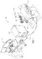
- FIG. 1is an illustration of a robotically controlled surgical system, according to one exemplary illustration
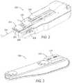
- FIG. 2is an illustration of an exemplary catheter assembly of the surgical system of FIG. 1 ;
- FIG. 3is another exemplary illustration of an exemplary catheter assembly of the surgical system of FIG. 1 ;
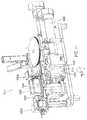
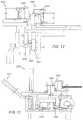
- FIG. 4is an illustration of an exemplary drive apparatus for an elongated member, e.g., a guidewire for a catheter;
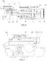
- FIG. 5is a top view of the exemplary drive apparatus of FIG. 4 ;
- FIG. 6is a side view of the exemplary drive apparatus of FIG. 4 ;
- FIG. 7is a rear view of the exemplary drive apparatus of FIG. 4 ;
- FIG. 8is a perspective view of the exemplary drive apparatus of FIG. 4 , with the dynamic gripper rotated to a maximum rotation in a clockwise direction;
- FIG. 9is a perspective view of the exemplary drive apparatus of FIG. 4 , with the dynamic gripper rotated to a maximum rotation in a counter-clockwise direction;
- FIG. 10is an illustration of another exemplary drive apparatus for an elongated member, e.g., a guidewire for a catheter;
- FIG. 11is another perspective view of the exemplary drive apparatus of FIG. 10 ;
- FIG. 13is a rear view of the exemplary drive apparatus of FIG. 10 ;
- FIG. 14is another perspective view of the exemplary drive apparatus of FIG. 10 , with the grippers placed in an open position;
- FIG. 15is a front view of an exemplary instrument with a sterile drape assembly
- FIG. 16is a graph illustrating an exemplary proxy command for a drive apparatus
- FIG. 17is a graph illustrating insert joint position for the exemplary proxy command illustrated in FIG. 16 ;
- FIG. 18is a process flow diagram for an exemplary method of providing a generally continuous motion using a discontinuous drive system, e.g., the exemplary drive apparatus illustrated in FIGS. 4-9 and/or FIGS. 10-14 ; and
- FIG. 19is a top view of an exemplary pivotable pad for a gripper.
- System 100may include a robotic catheter assembly 102 having a robotic or first or outer steerable complement, otherwise referred to as a sheath instrument 104 (generally referred to as “sheath” or “sheath instrument”) and/or a second or inner steerable component, otherwise referred to as a robotic catheter or guide or catheter instrument 106 (generally referred to as “catheter” or “catheter instrument”).
- Catheter assembly 102is controllable using a robotic instrument driver 108 (generally referred to as “instrument driver”).
- system 100includes an operator workstation 112 , an electronics rack 114 and associated bedside electronics box (not shown), a setup joint mounting brace 116 , and instrument driver 108 .
- operator workstation 112may include a computer monitor to display a three dimensional object, such as a catheter instrument or component thereof, e.g., a guidewire, catheter sheath.
- catheter instrument 502may be displayed within or relative to a three dimensional space, such as a body cavity or organ, e.g., a chamber of a patient's heart.
- a body cavity or organe.g., a chamber of a patient's heart.
- an operatoruses a computer mouse to move a control point around the display to control the position of catheter instrument.
- System componentsmay be coupled together via a plurality of cables or other suitable connectors 118 to provide for data communication, or one or more components may be equipped with wireless communication components to reduce or eliminate cables 118 . Communication between components may also be implemented over a network or over the internet. In this manner, a surgeon or other operator may control a surgical instrument while being located away from or remotely from radiation sources, thereby decreasing radiation exposure. Because of the option for wireless or networked operation, the surgeon may even be located remotely from the patient in a different room or building.
- an exemplary instrument assembly 200is shown, including sheath instrument 104 and the associated guide or catheter instrument 106 mounted to mounting plates 202 , 204 on a top portion of instrument driver 108 .
- catheter instrument 106is inserted within a central lumen of sheath instrument 104 such that instruments 104 , 106 are arranged in a coaxial manner.
- instruments 104 , 106are arranged coaxially, movement of each instrument 104 , 106 can be controlled and manipulated independently.
- instrument driver 108motors within instrument driver 108 are controlled such that carriages coupled to each of the instruments 104 , 160 may allow the instruments 104 , 106 to be driven forwards and backwards along the driver 108 , e.g., with mounting plates securing the instruments to the driver 108 on bearings.
- a catheter 300 coupled to guide catheter instrument 106 and sheath instrument 104can be controllably manipulated while inserted into the patient, as will be further illustrated.
- Additional instrument driver 108 motors(not shown in FIG. 2 ) may be activated to control bending of the catheter as well as the orientation of the distal tips thereof, including tools mounted at the distal tip.
- Sheath catheter instrument 106is configured to move forward and backward for effecting an axial motion of the catheter, e.g., to insert and withdraw the catheter from a patient, respectively.
- the instrument 109includes a cover 111 and a drive apparatus, e.g., drive apparatus 400 or drive apparatus 1000 , as will be described further below.
- a drive apparatuse.g., drive apparatus 400 or drive apparatus 1000
- the instrument 109may be used to manipulate an elongate member included in the catheter assembly 102 , e.g., a catheter guidewire (not shown in FIG. 3 ).
- the instrument 109may be employed to manipulate a catheter sheath (not shown in FIG. 3 ).
- a single instrument 109is illustrated in FIG.
- two instruments 109may be employed in which a first instrument 109 is used to insert and roll a guidewire, which guidewire is inserted within a central lumen of a second instrument 109 (not shown in FIG. 3 ) such that the two instruments 109 are arranged in a coaxial manner, substantially as described above regarding the instruments 104 , 106 .
- the instruments 109may generally insert and rotate the associated elongate member, i.e., the guidewire and catheter sheath, independently, as described above regarding the instruments 104 , 106 .
- the exemplary illustrations hereinmay generally focus on the insertion and rotation of a guidewire for a catheter, the instrument 109 may be used for insertion and rotation of any elongate member that is convenient.
- the drive apparatus 400may generally include a moveable component 440 .
- the moveable component 440is a dynamic gripper 440 .
- the drive apparatusmay further comprise a first component 442 .
- the first component 442may be a static gripper 442 , and in some exemplary approaches the static gripper 442 may be generally fixed with respect to the support surface 401 .
- Each of the grippers 440 , 442may comprise a clamp 445 , 447 having a pair of opposing pads 444 a , 444 b and 446 a , 446 b , respectively.
- the grippers 440 , 442may each selectively clamp an elongate member, e.g., a guidewire or catheter, between their respective opposing pads 444 a , 444 b and 446 a , 446 b.
- an elongate membere.g., a guidewire or catheter
- the moveable component or dynamic gripper 440may have a range of motion to which it is confined.
- the dynamic gripper 440may be capable of axial movement in a direction A along a distance D.
- the dynamic gripper 440may be capable of limited rotational movement about an axis parallel to the direction of axial movement, e.g., to a range of plus or minus a predetermined angle with respect to a normal or center position.
- the dynamic gripper 440may move an elongated component across a predetermined movement, e.g., an axial or rotational movement that may be provided by a user, that is greater than the axial or rotational range of motion.
- the pads 444may each generally define a length L D in the axial direction associated with the elongate member, as best seen in FIG. 5 .
- the pads 446may each generally define a length L S in the axial direction associated with the elongate member.
- the pads 444may also each define a height H D in a direction perpendicular to the axial direction, i.e., in a direction corresponding to a direction of top loading the elongate member, as will be described further below.
- the pads 446may similarly each define a height H S in a direction perpendicular to the axial direction, i.e., in a direction corresponding to a direction of top loading the elongate member, as will be described further below.
- An elongated membere.g., a guidewire
- a slip detection wheel 406that passively rotates in response to a length of the guidewire being moved by the dynamic grippers 440 .
- the slip detection wheel 406may be mounted on a rotatable member 405 .
- the wheel 406may include optical marks allowing for tracking of the wheel 406 rotation, thereby allowing measurement of movement and/or slippage of the elongate member.
- the grippersmay each be mounted to a support structure 401 , e.g., a top surface or support structure associated with the driver 108 .
- the grippers 440 , 432are each configured to selectively grip an elongate member such as a catheter guidewire or sheath, merely as examples.
- the dynamic gripper 440is configured to generally move axially and rotationally with respect to the support structure 401 to effect a corresponding axial and rotational movement of the elongated member.
- the static gripper 442is generally not movable axially or rotationally with respect to the support structure 401 . The static gripper 442 selectively closes and opens to grip and release the elongate member.
- the static gripper 442cooperates with the dynamic gripper 440 to effect axial movement (i.e., for insertion) along a direction A as illustrated in FIG. 4 , and rotational movement R about the direction A of the elongate member.
- the grippers 440 , 432may generally work in sequence such that at least one of the grippers 440 , 432 is gripping the elongate member at any given time. More specifically, during any movement of the guidewire, e.g., insertion, retraction, or rotational movement in either direction, the dynamic grippers 440 are closed, and static grippers 442 are open.
- a range of axial motion associated with the dynamic grippers 440may be finite, and in particular be limited to a predetermined axial distance D, as seen in FIG. 6 . Accordingly, upon reaching a limit to the range of motion, i.e., at an axially furthest position in one direction, the dynamic grippers 440 generally release the elongate member, move back in an opposite direction, and re-grip the elongated member for continued axial movement. While the dynamic grippers 440 are not gripping the elongated member, the static grippers 442 may hold the elongated member in place to prevent movement or loss of position.
- Axial and rotational motion of the elongated membermay be governed by independent drive systems associated with the drive apparatus 400 .
- the dynamic gripper 440may have separate motors or mechanisms controlling axial motion on the one hand and rotational motion on the other. Accordingly, insertion and rotation of the elongated member may be accomplished completely independently of the other. More specifically, the elongated member may be inserted axially while it is being rotated, or the elongated member may be inserted without any rotation. Moreover, the elongate member may be rotated without requiring any insertion motion at the same time.
- a rotation drive motor 423may rotate a gear 424 engaging a carriage or swing platform 425 configured to rotate about an axis of rotation, e.g., in a rotational motion R about the direction of insertion A.
- the carriage 425may be located by a pair of rolling posts 422 supported by a base structure 434 .
- the base structure 434may in turn be secured to the support structure 401 .
- the carriage or swing platform 425may be capable of rolling from a nominal or center position to any degree that is convenient.
- the carriage or swing platform 425may be capable of rolling 30 degrees in either direction from a nominal or center position. More specifically, as illustrated in FIG. 8 , swing platform 425 is rotated in a clock-wise direction thirty degrees away from a nominal or center position, i.e., as shown in FIG. 4 . Moreover, as illustrated in FIG. 9 , swing platform 425 is illustrated rotated in a counter-clock-wise direction away from the nominal position.
- the dynamic gripper 440may be axially moved by a shaft 426 which is linked to an axial drive motor 431 by way of cam 430 , as best seen in FIG. 6 .
- the cam 430may be connected to the motor 431 via gears 432 , 433 .
- the opposite end of the shaft 426may be connected to an axially movable platform 428 via a cam follower 427 .
- the dynamic gripper 440may be independently driven in an axial direction, e.g., for insertion, by the axial drive motor 431 , and may be rotated independently by a rotation drive motor 423 .
- the static and dynamic grippers 442 , 440may each be configured to open to allow loading of an elongated member, e.g., a guidewire or catheter. Moreover, the grippers 440 , 442 may generally allow “top loading” of the drive apparatus 400 in a direction perpendicular to the axial motion of the gripper 440 . More specifically, the grippers 440 , 442 may each generally open to allow the guidewire to be laid between the open grippers, e.g., from above the apparatus 400 , without needing to “thread” the elongated member into the grippers 440 , 442 axially.
- the ability to load the elongated member without requiring the catheter to be threaded through the drive apparatus 400advantageously saves time, and also facilitates use of a sterile drape as will be described further below.
- the dynamic gripper 440may be opened by a grip open motor 407 .
- a grip open motor 407may be provided which drives a cam 408 , which in turn actuates shaft 9 .
- the shaft 9has a cam follower 410 that provides axial motion to movable platform 411 and cam follower 412 , which is attached to the lever 413 (see FIG. 6 ).
- the lever 13as seen in FIG. 5 , provides lateral motion through a rotation over shaft 414 to a dynamic gripper bracket 416 by way of cam follower 415 .
- Cam 408thus may generally provide only one way motion, to open the dynamic grippers 440 .
- the dynamic grippersmay be urged toward a closed position by a set of springs 417 .
- the springs 417may act between the opposing pads included in the dynamic grippers 440 , thereby urging the grippers 440 into a closed position absent a force applied by the grip open motor 407 to counteract the closing force of the springs 417 .
- the static gripper 442may be selectively opened and closed, independent of the opening and closing of the dynamic gripper 440 .
- the same cam 408 employed to open the dynamic grippers 440may be used to selectively open the static grippers 442 .
- the cam 408may include two separate profiles, with one configured to open the dynamic grippers 440 , and another configured to open the static grippers 442 .
- the cam 408 as seen in FIG. 7may be in proximity to a cam follower 418 that is connected to static gripper platform 419 .
- the static gripper platform 419may urge the opposing pads of the static grippers 442 apart.
- One or more compliant elements, e.g., spring 420may generally urge the static gripper platform 419 toward a closed position where the static grippers 442 are clasped together, e.g., about a guidewire or catheter.
- the platform 425 on which the dynamic grippers 440 are mountedmay generally move in relation to the support surface 401 , as noted above.
- the platform 425thus may also be moving in relation to the cam follower 410 , shaft 409 , and cam 408 used to effect opening and closing movement of the dynamic grippers 440 .
- the movement of the shaft 409is in relation to the moving platform 425 , and thus the opening movement of the cam 408 may need to account for this additional relative movement in order to open the dynamic grippers 440 .
- the grippers 440 , 442generally allow a top loading of the elongated member, e.g., a guidewire, thereby increasing the speed with which the guidewire may be loaded into the drive apparatus 400 .
- the positioning of the grippers 440 , 442 and the opposing pads 444 , 446may also facilitate the use of a sterile drape that generally maximizes the potential for reusing components of the drive apparatus 400 .
- the sterile drapemay allow for keeping nearly the entire drive apparatus 400 out of the sterile environment, defining in part a disposable portion of the system 100 that is within the sterile environment.
- the drive apparatus 1000may generally include a moveable component such as a dynamic gripper 1050 .
- the drive apparatusmay further comprise a fixed component.
- the fixed componentincludes at least one static gripper.
- the fixed componentincludes two static grippers 1052 a , 1052 b . More specifically, the fixed component includes a first static gripper 1052 a , and a second static gripper 1052 b .
- the dynamic gripper 1050may comprise a pair of opposing pads 1003 , 1004 .
- a first one of the static grippers 1052 amay comprise a pair of opposing pads 1005 a , 1006 a
- the other static gripper 1052 bmay also comprise a pair of opposing pads 1005 b , 1006 b
- the grippers 1050 , 1052 a , and 1052 bmay each selectively clamp an elongate member, e.g., a guidewire or catheter, between their respective opposing pads 1003 / 1004 , 1005 a / 1006 a , and 1005 b / 1006 b .
- the pads 1003 / 1004 , 1005 a / 1006 a , and 1005 b / 1006 bmay each be relatively soft with respect to the particular elongate member being employed, in order to more securely grip the elongate member and minimize potential damage to the elongate member, e.g., by spreading grip load across an increased surface area of the elongate member.
- the pads 1003 , 1004 of the dynamic gripper 1050each define generally arcuate profiles for engaging the elongate member (not shown in FIGS. 12 and 13 ). More specifically, the pads 1003 , 1004 each have curved pad surfaces 1098 , 1099 , respectively. Accordingly, the pads 1003 , 1004 may engage an elongate member along a longitudinal line extending parallel to the elongate member, i.e., axially with respect to the dynamic gripper 1050 . In other exemplary approaches, the surfaces of the pads 1003 , 1004 may be generally flat.
- the pads 1005 a / 1006 a and 1005 b / 1006 b of the static grippers 1052 a , 1052 bmay similarly define either curved or flat engagement surfaces for engaging an elongate member.
- one of the pads 1003 ′ of a dynamic gripper 1050 ′may be pivotable about a substantially vertical axis A-A with respect to an opposing pad 1004 ′. While the pads 1003 / 1004 , 1005 a / 1006 a , and 1005 b / 1006 b described in regard to FIGS. 10-14 are illustrated as being generally fixed rotationally with respect to one another, a pivotable pad 1003 ′ may be employed in place of any of the rotationally fixed pads. The pivotable pad 1003 ′ may generally improve grip of an elongate member by minimizing any loss of grip due to misalignment of the pad 1003 ′ or 1004 ′.
- the pad 1003 ′will generally automatically rotate about the vertical axis A-A as the associated gripper, e.g., dynamic gripper 1050 , closes upon the elongate member.
- the pivoting pad 1003 ′may thereby ensure a substantially parallel alignment of the two pads 1003 ′, 1004 ′ as the gripper 1050 ′ closes upon the elongate member.
- the pivotable pad conceptmay be applied not only to a dynamic gripper 1050 ′, but also to a static gripper, e.g., static grippers 1052 a , 1052 b.
- the moveable component or dynamic gripper 1050 of the drive apparatus 1000may have a predetermined range of motion which it is confined to.
- the dynamic gripper 1050may be capable of axial movement in a direction A along a predetermined distance D 2 (see FIG. 10 ).
- the dynamic gripper 1050may be capable of imparting a limited rotational movement to the elongate member about an axis parallel to the direction of axial movement, e.g., to a range of plus or minus a predetermined angle with respect to a normal position.
- the pads 1003 , 1004 of the dynamic gripper 1050may generally translate vertically with respect to one another across a limited range of translational motion, e.g., as defined by a gear and rack system. Nevertheless, the dynamic gripper 1050 may move an elongated component across a movement, e.g., an axial or rotational movement, for example as commanded by a user or surgeon, that is greater than the predetermined axial or rotational motion capable of the dynamic gripper 1050 in a single vertical stroke of the dynamic grippers 1050 .
- the pads 1003 , 1004 of the dynamic gripper 1050may generally define a length L D in the axial direction associated with the elongate member, as best seen in FIG. 14 .
- the pads 1005 a , 1006 a and 1005 b , 1006 b of the first and second static grippers 1052 a , 1052 bmay generally define respective lengths L S1 , L S2 in the axial direction associated with the elongate member.
- the pads 1003 / 1004 , 1005 a / 1006 a , and 1005 b / 1006 bmay each generally define an axial height, i.e., in a direction perpendicular to the direction of axial insertion A and corresponding to a direction from which an elongated member may be placed in between the pads.
- the pads 1003 , 1004 of the dynamic grippers 1050may define respective axial heights H 2 and H 1 , which may be equal.
- the pads 1003 / 1004 , 1005 a / 1006 a , and 1005 b / 1006 bmay each generally be open to a space above the pads when opened, e.g., as shown in regard to the dynamic pads 1003 , 1004 in FIG. 12 , allowing an elongated member extending across the pads axially to be laid in between the pads 1003 / 1004 , 1005 a / 1006 a , and 1005 b / 1006 b.
- An elongated membere.g., a guidewire
- the slip detection wheel 1002may be mounted on a support 1001 .
- the wheel 1002may include optical marks allowing for tracking of the wheel 1002 rotation, thereby allowing measurement of movement of the elongate member. It should be noted that for stiffer elongate members, it may not be necessary to wrap the elongate member about the slip detection wheel. Instead, the wheel may be configured to just contact the elongate member and rotation is imparted to the passive wheel via friction between the wheel and the surface of the elongate member.
- the static grippers 1052 a , 1052 b and dynamic gripper 1050may each be mounted to a support structure 999 , e.g., a top surface or support structure associated with the driver 108 .
- the grippers 1050 , 1052are may each be configured to selectively grip an elongate member such as a catheter guidewire or sheath, merely as examples.
- the dynamic gripper 1050is configured to generally move axially with respect to the support structure 999 to effect a corresponding axial movement of the elongated member.
- the pads 1003 , 1004 of the dynamic gripper 1050are also configured to translate in a vertical direction across a fixed range of motion to impart rotational motion to the elongate member with respect to the support structure 999 .
- the static grippers 1052 a and 1052 bare generally not movable axially or rotationally with respect to the support structure 401 .
- the static grippers 1052 a and 1052 bselectively close and open to grip and release the elongate member.
- the static grippers 1052 a and 1052 b of the drive apparatus 1000each cooperate with the dynamic gripper 1050 to effect axial movement (i.e., for insertion or retraction) along a direction A as illustrated in FIG. 10 , and rotational movement R about the direction A of the elongate member.
- the static grippers 1052 a , 1052 bmay generally work in sequence with the dynamic grippers 1050 such that at least one of the grippers 1050 , 1052 a , and 1052 b is gripping the elongate member at any given time.
- the dynamic grippers 1050are closed, and the static grippers 1052 a and 1052 b are open.
- the static grippers 1052 a , 1052 bmay generally work in concert, such that the static grippers 1052 a , 1052 b are either both open or both closed together.
- a range of axial motion associated with the dynamic grippers 1050may be finite, and in particular be limited to a predetermined axial distance D 2 , as seen in FIG. 10 .
- a range of motion of the dynamic gripper 1050may be limited by the static gripper 1052 a on one end and the other static gripper 1052 b on the other end.
- the dynamic gripper 1050may have some predetermined range of axial motion.
- the dynamic grippers 1050upon reaching a limit to the range of motion, i.e., at an axially furthest position in one direction, the dynamic grippers 1050 generally release the elongate member, move back in an opposite direction, and re-grip the elongated member for continued axial movement. While the dynamic grippers 1050 are not gripping the elongated member, the static grippers 1052 a and/or 1052 b may hold the elongated member in place to prevent movement of the elongated member or loss of position.
- Axial and rotational motion of the elongated membermay be governed by independent drive systems associated with the drive apparatus 1000 , as with drive apparatus 400 .
- the dynamic gripper 1050may have separate motors or mechanisms controlling axial motion on the one hand and rotational motion on the other. Accordingly, insertion and rotation of the elongated member may be accomplished completely independently of the other. More specifically, the elongated member may be inserted axially while it is being rotated, or the elongated member may be inserted without any rotation. Moreover, the elongate member may be rotated without requiring any insertion motion at the same time.
- the drive apparatus 1000may be generally closed initially.
- lever 1011may be manually moved to a vertical position, e.g., as illustrated in FIG. 14 .
- the movement of the lever 1011may rotate a shaft 1012 that is configured to move a static pad bracket 1013 which in turn opens the static pads 1005 a and 1005 b with respect to their corresponding static pads 1006 a and 1006 b , respectively.
- a dynamic pad bracket 1014may open the dynamic pads 1003 , 1004 of the dynamic gripper 1050 in a similar manner.
- camsmay be positioned on the shaft 1012 for urging the brackets 1013 , 1014 in a direction opening the pads of each of the static grippers 1052 a , 1052 b and the dynamic grippers 1050 , respectively.
- the pads of the static grippers 1052 a , 1052 b and the dynamic grippers 1050may be opened in sequence, i.e., separately from one another.
- cams 1015 and 1016may be connected by a coupling 1017 that is driven by motor 1010 .
- the cams 1015 , 1016may act upon the static pad bracket 1013 and dynamic pad bracket 1014 , respectively, thereby opening each.
- the static pad bracket 1013may be urged into a closing position by a spring 1030
- the dynamic pad bracket 1014may be urged into a closing position by a spring 1031 . Accordingly, the static pad bracket 1013 and dynamic pad bracket 1014 generally may remain closed in the absence of a force applied to the brackets 1013 , 1014 tending to open either of the brackets 1013 , 1014 .
- Axial movement of the dynamic gripper 1050i.e., to effect an insertion or refraction motion of the dynamic gripper 1050 , may be driven by a cam 1007 that is turned by motor 1008 , as best seen in FIG. 11 .
- cam follower 1018may follow the cam, e.g., within a groove 1060 defined by the cam 1007 , thereby imparting axial motion to dynamic gripper 1050 , including both of the opposing pads 1003 , 1004 .
- a gear shaft 1020may be connected through a coupling to a dedicated motor 1009 (see FIG. 10 ).
- the gear shaft 1020may provide relative vertical motion to a first gear rack 1019 that is opposed by a second gear rack 1021 .
- the relative vertical motionis transferred to the dynamic gripper 1050 . More specifically, a first one of the pads 1003 of the dynamic gripper 1050 translates upward and downward with the first gear rack 1019 , while the other pad 1004 translates upward and downward with the second gear rack 1021 . Accordingly, the relative vertical movement between the pads 1003 , 1004 imparts a rolling motion to an elongate member held between the pads 1003 , 1004 .
- Pads 1003 and 1004may be designed to optimize the gripping and rolling performance of the elongate member.
- a high durometer material that does not engulf the elongate memberis used, which may generally prevent pads 1003 and 1004 from contacting each other. This ensures that the spring force closing the grippers is substantially entirely applied to the elongate member and is not transferred from one gripper to the other, ensuring reliable grip on the elongate member.
- the contact surface of the pads 1003 and 1004is beveled in a convex shape such that there is less chance that the pads will contact each other due to any misalignment or non parallelism in the gripper mechanism.
- the pads 1003 , 1004 of the dynamic grippers 1050 and the pads 1005 a , 1006 a , 1005 b , 1006 b of the static grippers 1052 a , 1052 bmay be manually opened with the lever 1011 , as best seen in FIG. 10 .
- An elongate membere.g., a guidewire, may be top loaded into the apparatus 1000 . More specifically, a guidewire may be loaded around wheel 1002 and laid in between the pads 1005 a and 1006 a of the first static gripper 1052 a , the pads 1003 and 1004 of the dynamic gripper 1050 , and the pads 1005 band 1006 b of the second static gripper 1052 b .
- the elongate membermay generally be laid between the pads 1003 / 1004 , 1005 a / 1006 a , and 1005 b / 1006 b from above, allowing the elongate member to be extended and laid in between the pads instead of requiring that the elongate member be threaded axially through the pads.
- an elongate membersuch as a guide wire or catheter will be pulled off of or pushed onto wheel 1002 , which may passively rotate according to the insertion motion driven by the dynamic gripper 1050 with respect to a wheel support 1001 of the drive apparatus 1000 .
- rotation of the wheel 1002may be monitored, e.g., by an optical sensor, to allow for measurement of any axial movement of the elongate member.
- the dynamic pads 1003 and 1004are generally closed, thereby trapping the elongate member therebetween as a result of a grip imparted to the elongate member or guidewire.
- the pads 1005 a , 1006 a of the first static gripper 1052 a and the pads 1005 b , 1006 b of the second static gripper 1052 bremain open, thereby generally freely allowing relative movement of the elongate member with respect to the static grippers 1052 a , 1052 b .
- the pads 1005 a , 1006 a of the first static gripper 1052 a and the pads 1005 b , 1006 b of the second static gripper 1052 bmay be closed.
- the pads 1003 and 1004 of the dynamic gripper 1050may then be opened, and moved within its range of motion (i.e., along distance D) to allow regripping of the elongated member, while the static grippers 1052 a , 1052 b maintain the axial and rotational position of the elongated member.
- the cyclemay then be repeated to allow further axial and/or rotational movement of the elongated member.
- An exemplary drape assemblymay include a sterile drape 500 generally positioned over the instrument 109 .
- the sterile environmentmay thereby be confined to the area above the drape 500 , allowing use and reuse of the instrument 109 and essentially all components thereof that are positioned beneath the drape.
- the drape 500may be positioned over a set of grippers 504 a , 504 b using associated caps 501 a , 501 b .
- the grippers 504 a , 504 bmay correspond to any of the static grippers 1052 a , 1052 b or dynamic grippers 1050 of the apparatus 1000 , or the static gripper 442 or dynamic gripper 440 of the apparatus 400 .
- the caps 501may be molded into the drape 500 , and may be fitted to the grippers 504 , thereby securing the drape 500 in place over the grippers 504 .
- the caps 501may generally allow for gripping of an elongated member, e.g., a guidewire or catheter, using the caps 500 , thereby allowing the elongated member to be in the sterile environment.
- the drape 500 and caps 501may be included in a disposable portion of the system 100 , i.e., which must be disposed of after a procedure, while substantially all components of the system 100 , and in particular the drive apparatus 400 or drive apparatus 1000 , is kept out of the sterile environment and therefore may be reused.
- apparatus 400 and apparatus 1000are both described as having one set of fixed grippers and one set of dynamic grippers, alternative approaches may have two pairs of dynamic grippers instead of one static pair and one dynamic pair.
- the second pair of dynamic grippersmay perform similar duties as the static grippers described herein with respect to the first set of dynamic grippers (i.e., hold the elongate member while the first dynamic gripper is returning).
- the second dynamic grippermay also apply axial and rotation movement just like the first dynamic gripper.
- the stroke length and gripper length shown for apparatuses 400 and 1000are also merely exemplary.
- the distance between the grippers which is approximately equal to the stroke lengthis shown to be approximately the same length as each of the grippers. This may not be true in all cases. For example, for stiffer elongate members that have greater buckling strength, there may be a significantly longer length between the grippers, or effectively a significantly longer stroke.
- the elongate member that is being manipulatedhas a high friction surface, then shorter grippers may be appropriate.
- the length of the static and dynamic grippersare shown to be equal. It is likely that the static gripper length may be shorter than the dynamic gripper since the static gripper just needs to hold the device.
- the rotational mechanism of apparatus 400is shown to have approximately 60° of rotation in both directions. Again, this is merely an exemplary illustration.
- the 60 degrees of rotationmay generally permit a doctor to intervene manually and remove the robotic system if the robotic system is stopped at any point during a procedure, and the guidewire will always be presentable towards the top of the mechanism for removal. If for example, there was 180° of rotational movement on this mechanism, there may be times when the grippers are inverted making it difficult to remove the guidewire.
- large rotational strokesmake it more difficult to manage the sterile barrier because eit may lead to more winding up of the drape. Nevertheless, any angle of rotation may be employed that is convenient.
- the elongate membermay also be a catheter, a sheath, a microcatheter, a therapeutic device such as a stent or balloon or artherectomy device for example.
- the dynamic gripper 440 of the apparatus 400 and the dynamic gripper 1050 of the apparatus 1000generally may have a finite range of motion in the axial direction, i.e., a range of motion across an axial distance D as best seen in FIGS. 6 and 10 , respectively. Additionally, the dynamic grippers 440 and 1050 have a finite range of rotational motion, i.e., a maximum angle from a nominal position as dictated by the configuration of the swing platform 425 seen in FIGS. 8 and 9 and the geared rack system 1019 , 1021 illustrated in FIG. 12 .
- the dynamic grippers 440 and 1050generally must release the guidewire as it reaches a position toward or at an end of its range of motion, move axially rearward and then re-grip the guidewire, and continue the axial insertion.
- the dynamic grippers 440 , 1050generally must release the guidewire as the swing platform 425 and geared rack system 1019 , 1021 reaches a maximum angular travel, allowing the respective systems to move in the opposite rotational direction and re-grip the guidewire to continue rotating the guidewire.
- the process of gripping and re-gripping an elongate membermay occur many times during a given axial or rotational movement command.
- the challengeis to track a continuous command, i.e., to move or rotate a certain amount, with a discontinuous mechanism having a maximum axial stroke length D or maximum angular rotation that is a smaller magnitude than the commanded movement.
- an intermediate or proxy commandis employed that is internal to a control system, e.g., included in operator workstation 112 or electronics rack 114 of the system 100 , or incorporated as part of the drive apparatus 400 or 1000 .
- the controllermay generally be aware of the above movement limitations of the mechanism, and may accordingly determine an appropriate movement in response to a given command.
- FIG. 16an exemplary proxy command is illustrated for an exemplary drive apparatus 400 .
- the thicker linerepresents a commanded position provided by the user of the system, while the thinner line illustrates an exemplary proxycommand.
- the proxy commandis generally developed internally by the controller based on the user command and the physical realities of the mechanism.
- the proxy commandmay track the user command tightly. Once the drive apparatus 400 , 1000 gets to the end of its range of motion, however, the proxy command may freeze while the mechanism clutches and resets to allow continued driving. When the mechanism is finished with its clutching motion, the proxy command then catches up with the drive command such that the deviation between the commanded position of the wire and the actual wire position is as small as possible for as short a period of time as possible.
- the motion of the proxy commandmay be controlled by a process using two general states for the proxy command: a “freeze” state and a “tracking” state. More specifically, the proxy command may enter the “freeze” state whenever the mechanism under control, i.e., the drive apparatus 400 , 1000 indicates that it cannot currently drive. For example, when a user is commanding an insertion motion of 40 millimeters and there is only 20 millimeters remaining the axial range of motion of the drive apparatus 400 , 1000 , the proxy command may enter the freeze state. Additionally, the freeze state associated with the proxy command may be employed for other purposes, such as when the drive mechanism is deactivated or taken off line, e.g., for diagnostics.
- the proxy commandspends most of the time in the tracking state.
- the proxy commandfollows the user command with dynamics that generally dictate how the proxy command catches up with the user command when it leaves the freeze state.
- the dynamicscan generally be tuned to achieve whatever behavior is desired for the particular drive apparatus 400 , 1000 .
- the dynamicsmay provide as smooth and slow a transition as possible, e.g., for procedures where insertion of an elongated member is necessarily very slow; alternatively, the dynamics may provide for as fast and abrupt a transition as possible, or any blend of the two extremes.
- the proxy commandis a filtered version of the user command.
- the filteris reset such that the filter naturally follows a smooth trajectory connecting the proxy command with the user command.
- a first order or second order low-pass filtermay be employed.
- a non-linear filterthat includes features such as limiting the maximum speed of the proxy may be employed.
- a second order filtermay advantageously mimic, in terms of the proxy command dynamics, a mass-spring-damper system, i.e., where the proxy can be thought of as a mass which is connected to the user command by a spring and a damper.
- a proxy commandmay be mapped to the actual joint commands of the mechanism in any manner that is convenient.
- the joint commandmay be reset at the end of every clutching cycle, i.e., when the dynamic grippers 440 , 1050 release, move to accommodate additional insertion or rotational motion, and re-grip the elongated member, to be at either the front or the end of the range of motion.
- the joint commandmay be incremented by the same amount as the proxy command was incremented every cycle. For example as illustrated in FIG. 17 , an actual joint position command that was sent to the drive apparatus 400 , 1000 for the same data set as shown in FIG. 16 .
- the drive apparatus 400 , 1000may be configured to track a user command for axial motion or rotation of the elongate member by increasing actual velocity of components of the drive apparatus 400 , 1000 relative to a velocity expected were releasing/re-gripping not necessary.
- the grippers 440 , 1050may increase a velocity of the movement, even in some cases “getting ahead” of the commanded motion.
- the movement of the elongate membermay be preventing from falling behind or falling undesirably far behind a commanded motion.
- a drive apparatus 400 , 1000 or associated control systemmay generally compensate for the need to release and re-grip the elongate member by increasing a velocity of a component associated with a commanded motion.
- an actual position of an elongated membermay be kept within a predetermined range of a commanded movement, i.e., slightly ahead or behind a commanded position, to account for the periodic releasing and re-gripping of the elongate member.
- any velocity or positional adjustmentsmay be performed without intervention by the surgeon, such that the process of releasing and re-gripping the elongate member is generally undetected.
- control of any buffer between the commanded position/velocity and actual position/velocitymay be quick enough that any positional difference or velocity different resulting from the need to start and stop movement of the elongated member to allow release and re-gripping may generally be imperceptible by the user, e.g., the surgeon.
- the process 1300is generally begins at block 1302 , where the process may query whether a commanded movement of the drive apparatus is within an associated limit to the range of motion.
- process 1300proceeds to block 1304 , where the tracking state is set.
- the proxy commandmay be equal to the user command.
- the process 1300proceeds to block 1306 , where the proxy command may enter the freeze state.
- the freeze statemay allow the drive apparatus 400 , 1000 to release and re-grip the elongated member in order to reduce or eliminate the shortfall between the commanded motion and the capability of the drive apparatus 400 , 1000 .
- the proxy commandmay enter the freeze state to allow the dynamic grippers 440 , 1050 to be released and rotated to allow greater range of rotational movement.
- the dynamic grippers 440 , 1050are opened to release the elongate member from their grip, and the dynamic grippers 440 , 1050 are then moved to allow greater range of motion and re-grip the elongate member to reduce or eliminate the shortfall between the proxy command and the user command.
- Process 1300may then proceed to block 1310 .
- the commanded positionmay be compared with the proxy command position, i.e., to determine any shortfall between the new position of the dynamic grippers 440 , 1050 and the desired or commanded position.
- the proxy commandmay be adjusted with the difference determined at block 1310 .
- the proxy commandmay be a filtered version of the comparison between the proxy command and the user command, in order to “smooth” the response of the system to differences between the commanded position and the current position of the dynamic grippers.
- the transitionmay be tuned according to the desired response. A relatively slower transition may be employed in situations where any relatively sudden or relative large movement is especially problematic, while a faster transition may be employed where speed or responsiveness is more essential. Process 1300 may then terminate.
- Operator workstation 112 , electronics rack 114 , drive apparatus 400 , and/or drive apparatus 1000may include a computer or a computer readable storage medium implementing the operation of drive and implementing the various methods and processes described herein, e.g., process 1300 .
- computing systems and/or devicesmay employ any of a number of computer operating systems, including, but by no means limited to, versions and/or varieties of the Microsoft Windows® operating system, the Unix operating system (e.g., the Solaris® operating system distributed by Oracle Corporation of Redwood Shores, Calif.), the AIX UNIX operating system distributed by International Business Machines of Armonk, N.Y., the Linux operating system, the Mac OS X and iOS operating systems distributed by Apple Inc. of Cupertino, Calif., and the Android operating system developed by the Open Handset Alliance.
- the Unix operating systeme.g., the Solaris® operating system distributed by Oracle Corporation of Redwood Shores, Calif.
- AIX UNIX operating systemdistributed by International Business Machines of Armonk, N.Y.
- the Linux operating systeme.g., the Mac OS X and iOS operating systems distributed by Apple Inc. of Cupertino, Calif.
- the Android operating systemdeveloped by the Open Handset Alliance.
- Computing devicesgenerally include computer-executable instructions, where the instructions may be executable by one or more computing devices such as those listed above.
- Computer-executable instructionsmay be compiled or interpreted from computer programs created using a variety of programming languages and/or technologies, including, without limitation, and either alone or in combination, JavaTM, C, C++, Visual Basic, Java Script, Perl, etc.
- a processore.g., a microprocessor
- receives instructionse.g., from a memory, a computer-readable medium, etc., and executes these instructions, thereby performing one or more processes, including one or more of the processes described herein.
- Such instructions and other datamay be stored and transmitted using a variety of computer-readable media.
- a computer-readable mediumincludes any non-transitory (e.g., tangible) medium that participates in providing data (e.g., instructions) that may be read by a computer (e.g., by a processor of a computer).
- a mediummay take many forms, including, but not limited to, non-volatile media and volatile media.
- Non-volatile mediamay include, for example, optical or magnetic disks and other persistent memory.
- Volatile mediamay include, for example, dynamic random access memory (DRAM), which typically constitutes a main memory.
- Such instructionsmay be transmitted by one or more transmission media, including coaxial cables, copper wire and fiber optics, including the wires that comprise a system bus coupled to a processor of a computer.
- Computer-readable mediainclude, for example, a floppy disk, a flexible disk, hard disk, magnetic tape, any other magnetic medium, a CD-ROM, DVD, any other optical medium, punch cards, paper tape, any other physical medium with patterns of holes, a RAM, a PROM, an EPROM, a FLASH-EEPROM, any other memory chip or cartridge, or any other medium from which a computer can read.
- Databases, data repositories or other data stores described hereinmay include various kinds of mechanisms for storing, accessing, and retrieving various kinds of data, including a hierarchical database, a set of files in a file system, an application database in a proprietary format, a relational database management system (RDBMS), etc.
- Each such data storeis generally included within a computing device employing a computer operating system such as one of those mentioned above, and are accessed via a network in any one or more of a variety of manners.
- a file systemmay be accessible from a computer operating system, and may include files stored in various formats.
- An RDBMSgenerally employs the Structured Query Language (SQL) in addition to a language for creating, storing, editing, and executing stored procedures, such as the PL/SQL language mentioned above.
- SQLStructured Query Language
- system elementsmay be implemented as computer-readable instructions (e.g., software) on one or more computing devices (e.g., servers, personal computers, etc.), stored on computer readable media associated therewith (e.g., disks, memories, etc.).
- a computer program productmay comprise such instructions stored on computer readable media for carrying out the functions described herein.
- an elongated member being used in connection with the drive apparatus 400may be fed from a feed wheel 406 .
- an elongated member associated with drive apparatus 1000may be fed from a wheel 1002 .
- the feed wheels 406 , 1002may be configured to generally determine whether, when, and/or to what degree the elongated member slips, e.g., axially, during axial motion imparted by the dynamic grippers 440 , 1050 .
- the pads 444 a, b of the dynamic gripper 440 and the pads 1003 , 1004 of the dynamic gripper 1050may include relatively high friction surfaces to prevent slippage of the elongated member, at times slippage may nonetheless occur, resulting in inaccuracies in the measured and commanded movements of the drive apparatuses 400 and 1000 , respectively. Accordingly, the feed wheels 406 , 1002 may be used as a comparison with the movement of the dynamic grippers 440 , 1050 to determine when slippage occurs, and to what degree.
- the feed wheel 406 , 1050may include an optical reader that measures actual rotation of the feed wheels 406 , 1002 ultimately determining a length of the elongated member that is actually deployed from the feed wheel 406 at any given time. The actual movement of the elongated member may be compared with the commanded axial movement to determine whether any slippage has occurred, and may subsequently adjust movement of the dynamic grippers 440 accordingly.
- a sensor(not shown in FIGS. 4-14 ) is within view of the feed wheels 406 , 1002 and is outside of the sterile environment such that it need not be replaced after a procedure. More specifically, if the feed wheels 406 , 1002 are within the sterile environment, a sensor may be placed on an opposite side of an optically clear section of a sterile drape (not shown in FIGS. 4-14 ), thereby allowing the sensor to remain outside the sterile environment and reduce the frequency with which the sensor itself must be sterilized or replaced. In another exemplary illustration, both the sensor and the feed wheels 406 , 1002 are outside the sterile environment. Merely as examples, a textured surface (not shown) may be positioned on the feed wheels 406 , 1002 that is detectable via the sensor. As such, a linear position of an elongate member may be detected using the sensor in any manner that is convenient.
- a sensor outside the sterile fieldis configured to detect motion of the elongate member and a feed wheel is not necessary.
- Thismay be suitable for elongate devices such as catheters that have a braided surface or guidewires that have stripes on the outer extrusion. This detail on the surface of the elongate member may be detected by the sensor to detect motion.
- one or more idle rollersmay be in communication with the elongated member, such that the rollers provide a measure of the length of the elongated member supplied. The measured length may then be compared with the commanded length in order to determine whether any slippage has occurred, allowing the system to adjust subsequent commands from the system.
Landscapes
- Health & Medical Sciences (AREA)
- Life Sciences & Earth Sciences (AREA)
- Engineering & Computer Science (AREA)
- Surgery (AREA)
- General Health & Medical Sciences (AREA)
- Public Health (AREA)
- Biomedical Technology (AREA)
- Heart & Thoracic Surgery (AREA)
- Veterinary Medicine (AREA)
- Animal Behavior & Ethology (AREA)
- Nuclear Medicine, Radiotherapy & Molecular Imaging (AREA)
- Medical Informatics (AREA)
- Molecular Biology (AREA)
- Pulmonology (AREA)
- Hematology (AREA)
- Anesthesiology (AREA)
- Robotics (AREA)
- Biophysics (AREA)
- Endoscopes (AREA)
- Media Introduction/Drainage Providing Device (AREA)
- Manipulator (AREA)
Abstract
Description
Claims (20)
Priority Applications (2)
| Application Number | Priority Date | Filing Date | Title |
|---|---|---|---|
| US15/229,639US10792112B2 (en) | 2013-03-15 | 2016-08-05 | Active drive mechanism with finite range of motion |
| US17/010,179US11660153B2 (en) | 2013-03-15 | 2020-09-02 | Active drive mechanism with finite range of motion |
Applications Claiming Priority (2)
| Application Number | Priority Date | Filing Date | Title |
|---|---|---|---|
| US13/838,777US9408669B2 (en) | 2013-03-15 | 2013-03-15 | Active drive mechanism with finite range of motion |
| US15/229,639US10792112B2 (en) | 2013-03-15 | 2016-08-05 | Active drive mechanism with finite range of motion |
Related Parent Applications (1)
| Application Number | Title | Priority Date | Filing Date |
|---|---|---|---|
| US13/838,777ContinuationUS9408669B2 (en) | 2013-03-15 | 2013-03-15 | Active drive mechanism with finite range of motion |
Related Child Applications (1)
| Application Number | Title | Priority Date | Filing Date |
|---|---|---|---|
| US17/010,179ContinuationUS11660153B2 (en) | 2013-03-15 | 2020-09-02 | Active drive mechanism with finite range of motion |
Publications (2)
| Publication Number | Publication Date |
|---|---|
| US20160338785A1 US20160338785A1 (en) | 2016-11-24 |
| US10792112B2true US10792112B2 (en) | 2020-10-06 |
Family
ID=50277109
Family Applications (3)
| Application Number | Title | Priority Date | Filing Date |
|---|---|---|---|
| US13/838,777Active2034-10-11US9408669B2 (en) | 2013-03-15 | 2013-03-15 | Active drive mechanism with finite range of motion |
| US15/229,639Active2034-07-24US10792112B2 (en) | 2013-03-15 | 2016-08-05 | Active drive mechanism with finite range of motion |
| US17/010,179Active2033-08-20US11660153B2 (en) | 2013-03-15 | 2020-09-02 | Active drive mechanism with finite range of motion |
Family Applications Before (1)
| Application Number | Title | Priority Date | Filing Date |
|---|---|---|---|
| US13/838,777Active2034-10-11US9408669B2 (en) | 2013-03-15 | 2013-03-15 | Active drive mechanism with finite range of motion |
Family Applications After (1)
| Application Number | Title | Priority Date | Filing Date |
|---|---|---|---|
| US17/010,179Active2033-08-20US11660153B2 (en) | 2013-03-15 | 2020-09-02 | Active drive mechanism with finite range of motion |
Country Status (2)
| Country | Link |
|---|---|
| US (3) | US9408669B2 (en) |
| EP (1) | EP2777595B1 (en) |
Cited By (19)
| Publication number | Priority date | Publication date | Assignee | Title |
|---|---|---|---|---|
| US10993775B2 (en)* | 2013-08-15 | 2021-05-04 | Intuitive Surgical Operations, Inc. | Robotic instrument driven element |
| US10993773B2 (en) | 2013-08-15 | 2021-05-04 | Intuitive Surgical Operations, Inc. | Instrument sterile adapter drive features |
| US11007024B2 (en) | 2016-07-14 | 2021-05-18 | Intuitive Surgical Operations, Inc. | Geared grip actuation for medical instruments |
| US11090124B2 (en) | 2013-08-15 | 2021-08-17 | Intuitive Surgical Operations, Inc. | Instrument sterile adapter drive interface |
| US11248686B2 (en) | 2013-08-15 | 2022-02-15 | Intuitive Surgical Operations, Inc. | Lever actuated gimbal plate |
| US11246672B2 (en) | 2019-08-15 | 2022-02-15 | Auris Health, Inc. | Axial motion drive devices, systems, and methods for a robotic medical system |
| US11382650B2 (en) | 2015-10-30 | 2022-07-12 | Auris Health, Inc. | Object capture with a basket |
| US11439419B2 (en) | 2019-12-31 | 2022-09-13 | Auris Health, Inc. | Advanced basket drive mode |
| US11497567B2 (en) | 2018-02-08 | 2022-11-15 | Intuitive Surgical Operations, Inc. | Jointed control platform |
| US11534249B2 (en) | 2015-10-30 | 2022-12-27 | Auris Health, Inc. | Process for percutaneous operations |
| US11564758B2 (en) | 2013-08-15 | 2023-01-31 | Intuitive Surgical Operations, Inc. | Preloaded surgical instrument interface |
| US11571229B2 (en) | 2015-10-30 | 2023-02-07 | Auris Health, Inc. | Basket apparatus |
| US11660151B2 (en) | 2007-12-21 | 2023-05-30 | Intuitive Surgical Operations, Inc. | Robotic surgical system with patient support |
| US11737845B2 (en) | 2019-09-30 | 2023-08-29 | Auris Inc. | Medical instrument with a capstan |
| US11771521B2 (en) | 2015-09-09 | 2023-10-03 | Auris Health, Inc. | Instrument device manipulator with roll mechanism |
| US11864842B2 (en) | 2018-09-28 | 2024-01-09 | Auris Health, Inc. | Devices, systems, and methods for manually and robotically driving medical instruments |
| US11896330B2 (en) | 2019-08-15 | 2024-02-13 | Auris Health, Inc. | Robotic medical system having multiple medical instruments |
| US11950872B2 (en) | 2019-12-31 | 2024-04-09 | Auris Health, Inc. | Dynamic pulley system |
| US12364557B2 (en) | 2018-06-27 | 2025-07-22 | Auris Health, Inc. | Alignment and attachment systems for medical instruments |
Families Citing this family (86)
| Publication number | Priority date | Publication date | Assignee | Title |
|---|---|---|---|---|
| US8414505B1 (en) | 2001-02-15 | 2013-04-09 | Hansen Medical, Inc. | Catheter driver system |
| US20090036900A1 (en)* | 2007-02-02 | 2009-02-05 | Hansen Medical, Inc. | Surgery methods using a robotic instrument system |
| US9254123B2 (en) | 2009-04-29 | 2016-02-09 | Hansen Medical, Inc. | Flexible and steerable elongate instruments with shape control and support elements |
| US9962229B2 (en) | 2009-10-12 | 2018-05-08 | Corindus, Inc. | System and method for navigating a guide wire |
| US20130030363A1 (en) | 2011-07-29 | 2013-01-31 | Hansen Medical, Inc. | Systems and methods utilizing shape sensing fibers |
| US20130317519A1 (en) | 2012-05-25 | 2013-11-28 | Hansen Medical, Inc. | Low friction instrument driver interface for robotic systems |
| US9668814B2 (en) | 2013-03-07 | 2017-06-06 | Hansen Medical, Inc. | Infinitely rotatable tool with finite rotating drive shafts |
| US10149720B2 (en) | 2013-03-08 | 2018-12-11 | Auris Health, Inc. | Method, apparatus, and a system for facilitating bending of an instrument in a surgical or medical robotic environment |
| US10080576B2 (en) | 2013-03-08 | 2018-09-25 | Auris Health, Inc. | Method, apparatus, and a system for facilitating bending of an instrument in a surgical or medical robotic environment |
| US9326822B2 (en) | 2013-03-14 | 2016-05-03 | Hansen Medical, Inc. | Active drives for robotic catheter manipulators |
| US20140277334A1 (en) | 2013-03-14 | 2014-09-18 | Hansen Medical, Inc. | Active drives for robotic catheter manipulators |
| US9173713B2 (en) | 2013-03-14 | 2015-11-03 | Hansen Medical, Inc. | Torque-based catheter articulation |
| US9498601B2 (en) | 2013-03-14 | 2016-11-22 | Hansen Medical, Inc. | Catheter tension sensing |
| US11213363B2 (en) | 2013-03-14 | 2022-01-04 | Auris Health, Inc. | Catheter tension sensing |
| US20140276936A1 (en) | 2013-03-15 | 2014-09-18 | Hansen Medical, Inc. | Active drive mechanism for simultaneous rotation and translation |
| US9452018B2 (en) | 2013-03-15 | 2016-09-27 | Hansen Medical, Inc. | Rotational support for an elongate member |
| US10376672B2 (en) | 2013-03-15 | 2019-08-13 | Auris Health, Inc. | Catheter insertion system and method of fabrication |
| US9408669B2 (en) | 2013-03-15 | 2016-08-09 | Hansen Medical, Inc. | Active drive mechanism with finite range of motion |
| US20140276647A1 (en) | 2013-03-15 | 2014-09-18 | Hansen Medical, Inc. | Vascular remote catheter manipulator |
| EP3060157B1 (en) | 2013-10-24 | 2019-12-11 | Auris Health, Inc. | System for robotic-assisted endolumenal surgery |
| WO2015142955A1 (en)* | 2014-03-17 | 2015-09-24 | Intuitive Surgical Operations, Inc. | Automated structure with pre-established arm positions in a teleoperated medical system |
| US10046140B2 (en) | 2014-04-21 | 2018-08-14 | Hansen Medical, Inc. | Devices, systems, and methods for controlling active drive systems |
| US10569052B2 (en) | 2014-05-15 | 2020-02-25 | Auris Health, Inc. | Anti-buckling mechanisms for catheters |
| US9561083B2 (en) | 2014-07-01 | 2017-02-07 | Auris Surgical Robotics, Inc. | Articulating flexible endoscopic tool with roll capabilities |
| US10159533B2 (en) | 2014-07-01 | 2018-12-25 | Auris Health, Inc. | Surgical system with configurable rail-mounted mechanical arms |
| US10792464B2 (en) | 2014-07-01 | 2020-10-06 | Auris Health, Inc. | Tool and method for using surgical endoscope with spiral lumens |
| EP3200718A4 (en) | 2014-09-30 | 2018-04-25 | Auris Surgical Robotics, Inc | Configurable robotic surgical system with virtual rail and flexible endoscope |
| US10499999B2 (en) | 2014-10-09 | 2019-12-10 | Auris Health, Inc. | Systems and methods for aligning an elongate member with an access site |
| WO2016090270A1 (en) | 2014-12-05 | 2016-06-09 | Corindus, Inc. | System and method for navigating a guide wire |
| WO2016164824A1 (en) | 2015-04-09 | 2016-10-13 | Auris Surgical Robotics, Inc. | Surgical system with configurable rail-mounted mechanical arms |
| US20160321810A1 (en)* | 2015-04-28 | 2016-11-03 | Pixart Imaging (Penang) Sdn. Bhd. | Optical navigation sensor, electronic device with optical navigation function and operation method thereof |
| US9622827B2 (en) | 2015-05-15 | 2017-04-18 | Auris Surgical Robotics, Inc. | Surgical robotics system |
| JP6824967B2 (en) | 2015-09-18 | 2021-02-03 | オーリス ヘルス インコーポレイテッド | Tubular net navigation |
| FR3044541B1 (en) | 2015-12-07 | 2017-12-29 | Robocath | ROBOTISE MODULE OF SOFT MEDICAL MEDICAL TRAINING |
| US10932861B2 (en) | 2016-01-14 | 2021-03-02 | Auris Health, Inc. | Electromagnetic tracking surgical system and method of controlling the same |
| US10932691B2 (en) | 2016-01-26 | 2021-03-02 | Auris Health, Inc. | Surgical tools having electromagnetic tracking components |
| US11324554B2 (en) | 2016-04-08 | 2022-05-10 | Auris Health, Inc. | Floating electromagnetic field generator system and method of controlling the same |
| US10454347B2 (en) | 2016-04-29 | 2019-10-22 | Auris Health, Inc. | Compact height torque sensing articulation axis assembly |
| US11241559B2 (en) | 2016-08-29 | 2022-02-08 | Auris Health, Inc. | Active drive for guidewire manipulation |
| US11903571B2 (en) | 2016-08-31 | 2024-02-20 | Beijing Surgerii Robotics Company Limited | Flexible surgical instrument system with prepositioned drive input |
| KR20230096148A (en) | 2016-08-31 | 2023-06-29 | 아우리스 헬스, 인코포레이티드 | Length conservative surgical instrument |
| CN106361433B (en)* | 2016-08-31 | 2018-11-27 | 北京术锐技术有限公司 | A kind of flexible operation tool system based on Continuum Structure |
| US10244926B2 (en) | 2016-12-28 | 2019-04-02 | Auris Health, Inc. | Detecting endolumenal buckling of flexible instruments |
| US10543048B2 (en) | 2016-12-28 | 2020-01-28 | Auris Health, Inc. | Flexible instrument insertion using an adaptive insertion force threshold |
| CN116271427A (en) | 2017-03-06 | 2023-06-23 | 科林达斯公司 | Replacement of percutaneous devices |
| KR101939256B1 (en)* | 2017-03-08 | 2019-01-16 | 재단법인 아산사회복지재단 | Catheter feeding apparatus |
| EP3417901A1 (en) | 2017-06-20 | 2018-12-26 | Siemens Healthcare GmbH | Autonomous catheterization assembly |
| US10022192B1 (en) | 2017-06-23 | 2018-07-17 | Auris Health, Inc. | Automatically-initialized robotic systems for navigation of luminal networks |
| US11026758B2 (en) | 2017-06-28 | 2021-06-08 | Auris Health, Inc. | Medical robotics systems implementing axis constraints during actuation of one or more motorized joints |
| JP6581162B2 (en)* | 2017-09-29 | 2019-09-25 | ファナック株式会社 | Processing system and processing machine control method |
| CN111770736A (en) | 2017-12-11 | 2020-10-13 | 奥瑞斯健康公司 | Systems and methods for instrument-based insertion architectures |
| US11510736B2 (en) | 2017-12-14 | 2022-11-29 | Auris Health, Inc. | System and method for estimating instrument location |
| EP3740150A4 (en) | 2018-01-17 | 2021-11-03 | Auris Health, Inc. | SURGICAL ROBOTIC SYSTEMS WITH IMPROVED ROBOTIC ARMS |
| KR102264368B1 (en) | 2018-01-17 | 2021-06-17 | 아우리스 헬스, 인코포레이티드 | Surgical platform with adjustable arm support |
| CN117958987A (en) | 2018-09-19 | 2024-05-03 | 科林达斯公司 | Robot-assisted movement of elongate medical devices |
| WO2020197671A1 (en) | 2019-03-22 | 2020-10-01 | Auris Health, Inc. | Systems and methods for aligning inputs on medical instruments |
| CN120392314A (en) | 2019-07-15 | 2025-08-01 | 西门子医疗血管介入机器人公司 | Systems, apparatus, and methods for robotic interventional surgery using multiple elongated medical devices |
| EP4245239A3 (en) | 2019-07-15 | 2023-11-15 | Corindus, Inc. | Systems and methods for a control station for robotic interventional procedures using a plurality of elongated medical devices |
| CN114364423B (en) | 2019-07-19 | 2023-03-31 | 科林达斯公司 | Load sensing of elongate medical devices in robotic actuation |
| US11134859B2 (en) | 2019-10-15 | 2021-10-05 | Imperative Care, Inc. | Systems and methods for multivariate stroke detection |
| US11501436B2 (en) | 2020-01-07 | 2022-11-15 | Cleerly, Inc. | Systems, methods, and devices for medical image analysis, diagnosis, risk stratification, decision making and/or disease tracking |
| US20220392065A1 (en) | 2020-01-07 | 2022-12-08 | Cleerly, Inc. | Systems, methods, and devices for medical image analysis, diagnosis, risk stratification, decision making and/or disease tracking |
| US11969280B2 (en) | 2020-01-07 | 2024-04-30 | Cleerly, Inc. | Systems, methods, and devices for medical image analysis, diagnosis, risk stratification, decision making and/or disease tracking |
| CN113729962B (en)* | 2021-07-05 | 2023-07-25 | 深圳市爱博医疗机器人有限公司 | From end device of intervention operation robot |
| JP7540118B6 (en) | 2021-07-05 | 2024-09-12 | 深▲せん▼愛博合創医療机器人有限公司 | Interventional Surgery Robot Slave Device |
| CN113729956B (en)* | 2021-07-05 | 2023-04-28 | 深圳市爱博医疗机器人有限公司 | From end device of intervention operation robot |
| US11903669B2 (en) | 2021-07-30 | 2024-02-20 | Corindus, Inc | Sterile drape for robotic drive |
| US11906009B2 (en) | 2021-07-30 | 2024-02-20 | Corindus, Inc. | Rotational joint assembly for robotic medical system |
| US11839440B2 (en) | 2021-07-30 | 2023-12-12 | Corindus, Inc. | Attachment for robotic medical system |
| US11844732B2 (en) | 2021-07-30 | 2023-12-19 | Corindus, Inc. | Support for securing a robotic system to a patient table |
| US12035989B2 (en) | 2021-08-02 | 2024-07-16 | Corindus, Inc. | Systems and methods for a control station for robotic interventional procedures using a plurality of elongated medical devices |
| US20230052862A1 (en) | 2021-08-12 | 2023-02-16 | Imperative Care, Inc. | Sterile packaging assembly for robotic interventional device |
| US12419703B2 (en) | 2022-08-01 | 2025-09-23 | Imperative Care, Inc. | Robotic drive system for achieving supra-aortic access |
| US12318161B2 (en) | 2021-10-05 | 2025-06-03 | Siemens Healthineers Endovascular Robotics, Inc. | Robotic actuation of elongated medical devices |
| US20250143657A1 (en) | 2022-03-10 | 2025-05-08 | Cleerly, Inc. | Systems, devices, and methods for non-invasive image-based plaque analysis and risk determination |
| US20250217981A1 (en) | 2022-03-10 | 2025-07-03 | Cleerly, Inc. | Systems, methods, and devices for image-based plaque analysis and risk determination |
| US12406365B2 (en) | 2022-03-10 | 2025-09-02 | Cleerly, Inc. | Systems, devices, and methods for non-invasive image-based plaque analysis and risk determination |
| US20240041480A1 (en) | 2022-08-02 | 2024-02-08 | Imperative Care, Inc. | Multi catheter system with integrated fluidics management |
| USD1069809S1 (en) | 2022-08-25 | 2025-04-08 | Kandu Health, Inc. | Display screen or portion thereof with graphical user interface |
| CN115887865B (en)* | 2022-09-30 | 2025-07-08 | 中国科学院自动化研究所 | Interventional instrument motion control device |
| US12257086B2 (en) | 2022-11-11 | 2025-03-25 | Siemens Healthineers Endovascular Robotics, Inc. | Arrangement for securing a robotic system to a patient table |
| US20240181213A1 (en) | 2022-12-01 | 2024-06-06 | Imperative Care, Inc. | Drive table with shuttle |
| US12377206B2 (en) | 2023-05-17 | 2025-08-05 | Imperative Care, Inc. | Fluidics control system for multi catheter stack |
| US12370344B2 (en)* | 2023-05-30 | 2025-07-29 | Remedy Robotics, Inc. | Systems, methods, and devices for advancing an endovascular instrument |
| US20240399117A1 (en)* | 2023-05-30 | 2024-12-05 | Remedy Robotics, Inc. | Systems, methods, and devices for advancing an endovascular instrument |
| US12370345B2 (en) | 2023-05-30 | 2025-07-29 | Remedy Robotics, Inc. | Systems, methods, and devices for advancing an endovascular instrument |
Citations (495)
| Publication number | Priority date | Publication date | Assignee | Title |
|---|---|---|---|---|
| US2556601A (en) | 1947-02-10 | 1951-06-12 | Niles Bement Pond Co | Multiple tapping head |
| US2566183A (en) | 1947-05-29 | 1951-08-28 | Skilsaw Inc | Portable power-driven tool |
| US2623175A (en) | 1949-03-25 | 1952-12-23 | Radiart Corp | Reel antenna |
| US2730699A (en) | 1952-02-01 | 1956-01-10 | Gen Dynamics Corp | Telemetering system |
| US2884808A (en) | 1957-10-23 | 1959-05-05 | Mueller Co | Drive for drilling machine |
| US3294183A (en) | 1964-09-30 | 1966-12-27 | Black & Decker Mfg Co | Power driven tools |
| US3472083A (en) | 1967-10-25 | 1969-10-14 | Lawrence S Schnepel | Torque wrench |
| US3513724A (en) | 1968-07-17 | 1970-05-26 | Monogram Ind Inc | Speed reduction mechanism |
| US3595074A (en) | 1968-10-30 | 1971-07-27 | Clarence Johnson | Torque transducer |
| US3734207A (en) | 1971-12-27 | 1973-05-22 | M Fishbein | Battery powered orthopedic cutting tool |
| US3739923A (en) | 1970-02-20 | 1973-06-19 | Tokyo Shibaura Electric Co | Manipulator |
| US3784031A (en) | 1970-08-21 | 1974-01-08 | Tokyo Shibaura Electric Co | Machine for performing work |
| US3835854A (en) | 1970-02-27 | 1974-09-17 | Jewett Ashley Holding Corp | Catheter advancing device with nip rollers |
| US3921536A (en)* | 1975-01-30 | 1975-11-25 | Hall Ski Lift Company Inc | Cable grip tester |
| US3926386A (en) | 1974-07-09 | 1975-12-16 | Us Air Force | Spool for wire deployment |
| US4141245A (en) | 1975-06-03 | 1979-02-27 | Brandstetter Heinz P | Device for the measurement of mechanical work and power |
| US4241884A (en) | 1979-03-20 | 1980-12-30 | George Lynch | Powered device for controlling the rotation of a reel |
| US4243034A (en) | 1978-10-17 | 1981-01-06 | Viggo Ab | Cannula or catheter assembly |
| US4351493A (en) | 1979-09-20 | 1982-09-28 | U.S. Philips Corporation | Tape tension control for a tape recorder |
| US4357843A (en) | 1980-10-31 | 1982-11-09 | Peck-O-Matic, Inc. | Tong apparatus for threadedly connecting and disconnecting elongated members |
| US4384493A (en) | 1980-02-18 | 1983-05-24 | Gruenbaum Heinrich | Torque measuring device |
| US4507026A (en) | 1982-09-29 | 1985-03-26 | Boeing Aerospace Company | Depth control assembly |
| US4530471A (en) | 1981-03-05 | 1985-07-23 | Inoue-Japax Research Incorporated | Method of and apparatus for dispensing wire from a wire storage spool |
| US4555960A (en) | 1983-03-23 | 1985-12-03 | Cae Electronics, Ltd. | Six degree of freedom hand controller |
| US4688555A (en) | 1986-04-25 | 1987-08-25 | Circon Corporation | Endoscope with cable compensating mechanism |
| US4745908A (en) | 1987-05-08 | 1988-05-24 | Circon Corporation | Inspection instrument fexible shaft having deflection compensation means |
| US4784150A (en) | 1986-11-04 | 1988-11-15 | Research Corporation | Surgical retractor and blood flow monitor |
| US4857058A (en) | 1988-07-11 | 1989-08-15 | Payton Hugh W | Support patch for intravenous catheter |
| US4907168A (en) | 1988-01-11 | 1990-03-06 | Adolph Coors Company | Torque monitoring apparatus |
| US4945305A (en) | 1986-10-09 | 1990-07-31 | Ascension Technology Corporation | Device for quantitatively measuring the relative position and orientation of two bodies in the presence of metals utilizing direct current magnetic fields |
| US4945790A (en) | 1989-08-07 | 1990-08-07 | Arthur Golden | Multi-purpose hand tool |
| US5078714A (en) | 1990-03-02 | 1992-01-07 | Jefferson Katims | Method and apparatus for placement of a probe in the body and the medical procedure for guiding and locating a catheter or probe in the body |
| US5207128A (en) | 1992-03-23 | 1993-05-04 | Weatherford-Petco, Inc. | Tong with floating jaws |
| US5234428A (en) | 1991-06-11 | 1993-08-10 | Kaufman David I | Disposable electrocautery/cutting instrument with integral continuous smoke evacuation |
| US5256150A (en) | 1991-12-13 | 1993-10-26 | Endovascular Technologies, Inc. | Large-diameter expandable sheath and method |
| US5277085A (en) | 1991-11-26 | 1994-01-11 | Bridgestone Corporation | Multi-shaft electrically-operated automatic nut runner |
| US5339799A (en) | 1991-04-23 | 1994-08-23 | Olympus Optical Co., Ltd. | Medical system for reproducing a state of contact of the treatment section in the operation unit |
| US5341807A (en) | 1992-06-30 | 1994-08-30 | American Cardiac Ablation Co., Inc. | Ablation catheter positioning system |
| US5346498A (en) | 1991-11-06 | 1994-09-13 | Imagyn Medical, Inc. | Controller for manipulation of instruments within a catheter |
| US5350101A (en)* | 1990-11-20 | 1994-09-27 | Interventional Technologies Inc. | Device for advancing a rotatable tube |
| US5368015A (en) | 1991-03-18 | 1994-11-29 | Wilk; Peter J. | Automated surgical system and apparatus |
| US5394875A (en) | 1993-10-21 | 1995-03-07 | Lewis; Judith T. | Automatic ultrasonic localization of targets implanted in a portion of the anatomy |
| US5397443A (en) | 1990-12-31 | 1995-03-14 | Invacare Corporation | Method of assembling tubular electrochemical oxygen generators |
| US5398691A (en) | 1993-09-03 | 1995-03-21 | University Of Washington | Method and apparatus for three-dimensional translumenal ultrasonic imaging |
| US5408409A (en) | 1990-05-11 | 1995-04-18 | International Business Machines Corporation | Image-directed robotic system for precise robotic surgery including redundant consistency checking |
| JPH07136173A (en) | 1993-11-15 | 1995-05-30 | Olympus Optical Co Ltd | Manipulator for operation |
| US5426687A (en) | 1992-07-07 | 1995-06-20 | Innovative Care Ltd. | Laser targeting device for use with image intensifiers in surgery |
| US5447529A (en) | 1994-01-28 | 1995-09-05 | Philadelphia Heart Institute | Method of using endocardial impedance for determining electrode-tissue contact, appropriate sites for arrhythmia ablation and tissue heating during ablation |
| US5469857A (en) | 1993-03-12 | 1995-11-28 | Siemens Elema Ab | Apparatus for measuring electrical activity in the heart with graphical display of electrode contact with tissue |
| US5477856A (en) | 1991-02-15 | 1995-12-26 | Lundquist; Ingemar H. | Torquable catheter and torquable tubular member for use therewith |
| US5492131A (en) | 1994-09-06 | 1996-02-20 | Guided Medical Systems, Inc. | Servo-catheter |
| US5507725A (en) | 1992-12-23 | 1996-04-16 | Angeion Corporation | Steerable catheter |
| US5524180A (en) | 1992-08-10 | 1996-06-04 | Computer Motion, Inc. | Automated endoscope system for optimal positioning |
| US5559294A (en) | 1994-09-15 | 1996-09-24 | Condux International, Inc. | Torque measuring device |
| US5600330A (en) | 1994-07-12 | 1997-02-04 | Ascension Technology Corporation | Device for measuring position and orientation using non-dipole magnet IC fields |
| US5631973A (en) | 1994-05-05 | 1997-05-20 | Sri International | Method for telemanipulation with telepresence |
| US5662108A (en) | 1992-09-23 | 1997-09-02 | Endocardial Solutions, Inc. | Electrophysiology mapping system |
| WO1997044089A1 (en) | 1996-05-17 | 1997-11-27 | Biosense Inc. | Self-aligning catheter |
| US5697377A (en) | 1995-11-22 | 1997-12-16 | Medtronic, Inc. | Catheter mapping system and method |
| DE19649082C1 (en) | 1996-11-27 | 1998-01-08 | Fraunhofer Ges Forschung | Remote control unit for implement with holder and two hexapods |
| US5709661A (en) | 1992-04-14 | 1998-01-20 | Endo Sonics Europe B.V. | Electronic catheter displacement sensor |
| US5713946A (en) | 1993-07-20 | 1998-02-03 | Biosense, Inc. | Apparatus and method for intrabody mapping |
| US5722959A (en) | 1995-10-24 | 1998-03-03 | Venetec International, Inc. | Catheter securement device |
| US5738096A (en) | 1993-07-20 | 1998-04-14 | Biosense, Inc. | Cardiac electromechanics |
| US5749362A (en) | 1992-05-27 | 1998-05-12 | International Business Machines Corporation | Method of creating an image of an anatomical feature where the feature is within a patient's body |
| US5754741A (en) | 1992-08-10 | 1998-05-19 | Computer Motion, Inc. | Automated endoscope for optimal positioning |
| US5762458A (en) | 1996-02-20 | 1998-06-09 | Computer Motion, Inc. | Method and apparatus for performing minimally invasive cardiac procedures |
| US5767840A (en) | 1996-06-28 | 1998-06-16 | International Business Machines Corporation | Six-degrees-of-freedom movement sensor having strain gauge mechanical supports |
| US5779623A (en) | 1993-10-08 | 1998-07-14 | Leonard Medical, Inc. | Positioner for medical instruments |
| US5784542A (en) | 1995-09-07 | 1998-07-21 | California Institute Of Technology | Decoupled six degree-of-freedom teleoperated robot system |
| US5792135A (en) | 1996-05-20 | 1998-08-11 | Intuitive Surgical, Inc. | Articulated surgical instrument for performing minimally invasive surgery with enhanced dexterity and sensitivity |
| US5799055A (en) | 1996-05-15 | 1998-08-25 | Northwestern University | Apparatus and method for planning a stereotactic surgical procedure using coordinated fluoroscopy |
| CA2285342A1 (en) | 1997-04-01 | 1998-10-08 | Axel Muntermann | Method and device for detecting catheter-tissue contact and interaction with tissue during catheter ablation |
| US5825982A (en) | 1995-09-15 | 1998-10-20 | Wright; James | Head cursor control interface for an automated endoscope system for optimal positioning |
| US5833608A (en) | 1993-10-06 | 1998-11-10 | Biosense, Inc. | Magnetic determination of position and orientation |
| US5836990A (en) | 1997-09-19 | 1998-11-17 | Medtronic, Inc. | Method and apparatus for determining electrode/tissue contact |
| US5836869A (en) | 1994-12-13 | 1998-11-17 | Olympus Optical Co., Ltd. | Image tracking endoscope system |
| US5836874A (en) | 1996-04-08 | 1998-11-17 | Ep Technologies, Inc. | Multi-function electrode structures for electrically analyzing and heating body tissue |
| US5843076A (en) | 1995-06-12 | 1998-12-01 | Cordis Webster, Inc. | Catheter with an electromagnetic guidance sensor |
| US5842390A (en)* | 1996-02-28 | 1998-12-01 | Frank's Casing Crew And Rental Tools Inc. | Dual string backup tong |
| US5845646A (en) | 1996-11-05 | 1998-12-08 | Lemelson; Jerome | System and method for treating select tissue in a living being |
| US5855583A (en) | 1996-02-20 | 1999-01-05 | Computer Motion, Inc. | Method and apparatus for performing minimally invasive cardiac procedures |
| US5878193A (en) | 1992-08-10 | 1999-03-02 | Computer Motion, Inc. | Automated endoscope system for optimal positioning |
| US5876325A (en) | 1993-11-02 | 1999-03-02 | Olympus Optical Co., Ltd. | Surgical manipulation system |
| US5891095A (en) | 1993-05-10 | 1999-04-06 | Arthrocare Corporation | Electrosurgical treatment of tissue in electrically conductive fluid |
| US5921968A (en) | 1997-11-25 | 1999-07-13 | Merit Medical Systems, Inc. | Valve apparatus with adjustable quick-release mechanism |
| US5925078A (en) | 1994-01-19 | 1999-07-20 | The General Hospital Corporation | Methods and apparatus for joining collagen-containing materials |
| US5935079A (en) | 1994-03-31 | 1999-08-10 | Ep Technologies, Inc. | Systems and methods for positioning multiple electrode structures in electrical contact with the myocardium |
| US5950629A (en) | 1991-06-13 | 1999-09-14 | International Business Machines Corporation | System for assisting a surgeon during surgery |
| US5953683A (en) | 1997-10-09 | 1999-09-14 | Ascension Technology Corporation | Sourceless orientation sensor |
| US5951475A (en) | 1997-09-25 | 1999-09-14 | International Business Machines Corporation | Methods and apparatus for registering CT-scan data to multiple fluoroscopic images |
| US5967934A (en) | 1995-06-27 | 1999-10-19 | Matsushita Electric Works, Ltd. | Planetary transmission with releaseable one way clutch |
| US6004271A (en) | 1998-05-07 | 1999-12-21 | Boston Scientific Corporation | Combined motor drive and automated longitudinal position translator for ultrasonic imaging system |
| WO2000011495A1 (en) | 1998-08-21 | 2000-03-02 | Tomtec Imaging Systems Gmbh | Method and device for recording ultrasonic images |
| US6061587A (en) | 1997-05-15 | 2000-05-09 | Regents Of The University Of Minnesota | Method and apparatus for use with MR imaging |
| US6063022A (en) | 1997-01-03 | 2000-05-16 | Biosense, Inc. | Conformal catheter |
| US6063095A (en) | 1996-02-20 | 2000-05-16 | Computer Motion, Inc. | Method and apparatus for performing minimally invasive surgical procedures |
| US6080181A (en) | 1995-06-07 | 2000-06-27 | Sri International | System and method for releasably holding a surgical instrument |
| US6084371A (en) | 1999-02-19 | 2000-07-04 | Lockheed Martin Energy Research Corporation | Apparatus and methods for a human de-amplifier system |
| US6096004A (en) | 1998-07-10 | 2000-08-01 | Mitsubishi Electric Information Technology Center America, Inc. (Ita) | Master/slave system for the manipulation of tubular medical tools |
| WO2000045193A1 (en) | 1999-01-28 | 2000-08-03 | Tomtec Imaging Systems Gmbh | Method for compensating motion in ultrasound images of an object |
| US6106511A (en) | 1993-05-14 | 2000-08-22 | Sri International | Methods and devices for positioning a surgical instrument at a surgical site |
| US6129668A (en) | 1997-05-08 | 2000-10-10 | Lucent Medical Systems, Inc. | System and method to determine the location and orientation of an indwelling medical device |
| US6132368A (en) | 1996-12-12 | 2000-10-17 | Intuitive Surgical, Inc. | Multi-component telepresence system and method |
| US6154000A (en) | 1994-09-07 | 2000-11-28 | Omnitek Research & Development, Inc. | Apparatus for providing a controlled deflection and/or actuator apparatus |
| US6161032A (en) | 1998-03-30 | 2000-12-12 | Biosense, Inc. | Three-axis coil sensor |
| US6171234B1 (en) | 1998-09-25 | 2001-01-09 | Scimed Life Systems, Inc. | Imaging gore loading tool |
| US6172499B1 (en) | 1999-10-29 | 2001-01-09 | Ascension Technology Corporation | Eddy current error-reduced AC magnetic position measurement system |
| US6185478B1 (en) | 1997-05-29 | 2001-02-06 | Seiko Epson Corporation | Printing apparatus, control method for a printing apparatus, and recording medium for recording a control program for a printing apparatus |
| US6203493B1 (en) | 1996-02-15 | 2001-03-20 | Biosense, Inc. | Attachment with one or more sensors for precise position determination of endoscopes |
| US6226543B1 (en) | 1998-09-24 | 2001-05-01 | Super Dimension Ltd. | System and method of recording and displaying in context of an image a location of at least one point-of-interest in a body during an intra-body medical procedure |
| US6228028B1 (en) | 1996-11-07 | 2001-05-08 | Tomtec Imaging Systems Gmbh | Method and apparatus for ultrasound image reconstruction |
| US6233504B1 (en) | 1998-04-16 | 2001-05-15 | California Institute Of Technology | Tool actuation and force feedback on robot-assisted microsurgery system |
| US6233476B1 (en) | 1999-05-18 | 2001-05-15 | Mediguide Ltd. | Medical positioning system |
| US6246200B1 (en) | 1998-08-04 | 2001-06-12 | Intuitive Surgical, Inc. | Manipulator positioning linkage for robotic surgery |
| WO2001051993A1 (en) | 2000-01-14 | 2001-07-19 | Advanced Micro Devices, Inc. | System, method and photomask for compensating aberrations in a photolithography patterning system |
| US6266551B1 (en) | 1996-02-15 | 2001-07-24 | Biosense, Inc. | Catheter calibration and usage monitoring system |
| US20010009976A1 (en) | 1997-09-26 | 2001-07-26 | Ep Technologies, Inc. | Systems for recording use of structures deployed in association with heart tissue |
| US6272371B1 (en) | 1997-01-03 | 2001-08-07 | Biosense Inc. | Bend-responsive catheter |
| US6289579B1 (en) | 1999-03-23 | 2001-09-18 | Motorola, Inc. | Component alignment and transfer apparatus |
| US6301496B1 (en) | 1998-07-24 | 2001-10-09 | Biosense, Inc. | Vector mapping of three-dimensionally reconstructed intrabody organs and method of display |
| US20010029366A1 (en) | 1993-10-15 | 2001-10-11 | Swanson David K. | Composite structures and methods for ablating tissue to form complex lesion patterns in the treatment of cardiac conditions and the like |
| US6309397B1 (en) | 1999-12-02 | 2001-10-30 | Sri International | Accessories for minimally invasive robotic surgery and methods |
| US6310828B1 (en) | 1997-07-18 | 2001-10-30 | Tomtec Imaging Systems Gmbh | Method and device for sensing ultrasound images |
| US6312435B1 (en) | 1999-10-08 | 2001-11-06 | Intuitive Surgical, Inc. | Surgical instrument with extended reach for use in minimally invasive surgery |
| US20010042643A1 (en) | 2000-01-12 | 2001-11-22 | Volker Krueger | Steerable modular drilling assembly |
| US6331181B1 (en) | 1998-12-08 | 2001-12-18 | Intuitive Surgical, Inc. | Surgical robotic tools, data architecture, and use |
| US6363279B1 (en) | 1996-01-08 | 2002-03-26 | Impulse Dynamics N.V. | Electrical muscle controller |
| US6370411B1 (en) | 1998-02-10 | 2002-04-09 | Biosense, Inc. | Catheter calibration |
| US20020045905A1 (en) | 1998-12-08 | 2002-04-18 | Gerbi Craig Richard | Tool guide and method for introducing an end effector to a surgical site in minimally invasive surgery |
| US6375471B1 (en) | 1998-07-10 | 2002-04-23 | Mitsubishi Electric Research Laboratories, Inc. | Actuator for independent axial and rotational actuation of a catheter or similar elongated object |
| US6380732B1 (en) | 1997-02-13 | 2002-04-30 | Super Dimension Ltd. | Six-degree of freedom tracking system having a passive transponder on the object being tracked |
| US6381483B1 (en) | 1998-03-25 | 2002-04-30 | Olympus Optical Co., Ltd. | Therapeutic system |
| US6384483B1 (en) | 1997-02-06 | 2002-05-07 | Nec Corporation | Manufacturing method for semiconductor device |
| US6393340B2 (en) | 1995-04-21 | 2002-05-21 | International Business Machines Corporation | Robotic mechanisms with active and passive joints |
| US6394998B1 (en) | 1999-01-22 | 2002-05-28 | Intuitive Surgical, Inc. | Surgical tools for use in minimally invasive telesurgical applications |
| US6400979B1 (en) | 1997-02-20 | 2002-06-04 | Johns Hopkins University | Friction transmission with axial loading and a radiolucent surgical needle driver |
| US6398731B1 (en) | 1997-07-25 | 2002-06-04 | Tomtec Imaging Systems Gmbh | Method for recording ultrasound images of moving objects |
| US6401572B1 (en) | 2001-06-29 | 2002-06-11 | Dan Provost | Torque tool |
| US6415171B1 (en) | 1999-07-16 | 2002-07-02 | International Business Machines Corporation | System and method for fusing three-dimensional shape data on distorted images without correcting for distortion |
| US20020087169A1 (en) | 1998-02-24 | 2002-07-04 | Brock David L. | Flexible instrument |
| US6424885B1 (en) | 1999-04-07 | 2002-07-23 | Intuitive Surgical, Inc. | Camera referenced control in a minimally invasive surgical apparatus |
| US20020098938A1 (en) | 2001-01-23 | 2002-07-25 | Rodney Milbourne | First stage clutch |
| US20020100254A1 (en) | 2000-10-12 | 2002-08-01 | Dsd Communications, Inc. | System and method for targeted advertising and marketing |
| US20020107573A1 (en) | 1999-03-07 | 2002-08-08 | Discure Ltd. | Method and apparatus for computerized surgery |
| US6436107B1 (en) | 1996-02-20 | 2002-08-20 | Computer Motion, Inc. | Method and apparatus for performing minimally invasive surgical procedures |
| US20020117017A1 (en) | 2000-10-20 | 2002-08-29 | Gerd Bernhardt | Control Lever |
| WO2002074178A2 (en) | 2001-02-15 | 2002-09-26 | Endovia Medical, Inc. | Flexible surgical instrument |
| US20020138009A1 (en) | 1998-09-24 | 2002-09-26 | Data Sciences International, Inc. | Implantable sensor with wireless communication |
| US20020156369A1 (en) | 2001-04-19 | 2002-10-24 | Chakeres Donald W. | Simplified stereotactic apparatus and methods |
| US20020161426A1 (en) | 2001-04-26 | 2002-10-31 | Octavian Iancea | Collapsing machine and procedure for tubular nitinol stents |
| US20020161355A1 (en) | 1999-08-27 | 2002-10-31 | Helmut Wollschlager | Device for handling a catheter |
| US20020177789A1 (en)* | 2001-05-06 | 2002-11-28 | Ferry Steven J. | System and methods for advancing a catheter |
| US6487940B2 (en) | 2001-01-23 | 2002-12-03 | Associated Toolmakers Incorporated | Nut driver |
| US6493573B1 (en) | 1999-10-28 | 2002-12-10 | Winchester Development Associates | Method and system for navigating a catheter probe in the presence of field-influencing objects |
| US6493608B1 (en) | 1999-04-07 | 2002-12-10 | Intuitive Surgical, Inc. | Aspects of a control system of a minimally invasive surgical apparatus |
| US6530913B1 (en) | 1997-04-04 | 2003-03-11 | Jeffrey Giba | Steerable catheter |
| US20030050649A1 (en) | 1998-02-24 | 2003-03-13 | Brock David L. | Surgical instrument |
| US20030056561A1 (en) | 2001-04-13 | 2003-03-27 | Werner Butscher | Robot and method for bending orthodontic archwires and other medical devices |
| US6544230B1 (en) | 1998-03-31 | 2003-04-08 | Transvascular, Inc. | Catheters, systems and methods for percutaneous in situ arterio-venous bypass |
| US20030074011A1 (en) | 1998-09-24 | 2003-04-17 | Super Dimension Ltd. | System and method of recording and displaying in context of an image a location of at least one point-of-interest in a body during an intra-body medical procedure |
| US20030073908A1 (en) | 1996-04-26 | 2003-04-17 | 2000 Injectx, Inc. | Method and apparatus for delivery of genes, enzymes and biological agents to tissue cells |
| US6550128B1 (en) | 1998-02-14 | 2003-04-22 | Weatherford/Lamb, Inc. | Apparatus and method for handling of tubulars |
| US6551273B1 (en) | 2000-08-23 | 2003-04-22 | Scimed Life Systems, Inc. | Catheter having a shaft keeper |
| US6565554B1 (en) | 1999-04-07 | 2003-05-20 | Intuitive Surgical, Inc. | Friction compensation in a minimally invasive surgical apparatus |
| US20030109780A1 (en) | 2001-06-07 | 2003-06-12 | Inria Roquencourt | Methods and apparatus for surgical planning |
| US6580938B1 (en) | 1997-02-25 | 2003-06-17 | Biosense, Inc. | Image-guided thoracic therapy and apparatus therefor |
| US6587750B2 (en) | 2001-09-25 | 2003-07-01 | Intuitive Surgical, Inc. | Removable infinite roll master grip handle and touch sensor for robotic surgery |
| US6594552B1 (en) | 1999-04-07 | 2003-07-15 | Intuitive Surgical, Inc. | Grip strength with tactile feedback for robotic surgery |
| US20030135204A1 (en) | 2001-02-15 | 2003-07-17 | Endo Via Medical, Inc. | Robotically controlled medical instrument with a flexible section |
| US6610007B2 (en) | 2000-04-03 | 2003-08-26 | Neoguide Systems, Inc. | Steerable segmented endoscope and method of insertion |
| US6615155B2 (en) | 2000-03-09 | 2003-09-02 | Super Dimension Ltd. | Object tracking using a single sensor or a pair of sensors |
| US6618612B1 (en) | 1996-02-15 | 2003-09-09 | Biosense, Inc. | Independently positionable transducers for location system |
| WO2003077769A1 (en) | 2002-03-15 | 2003-09-25 | Power Medical Interventions, Inc. | Drive shaft for an electro-mechanical surgical device |
| US6626899B2 (en) | 1999-06-25 | 2003-09-30 | Nidus Medical, Llc | Apparatus and methods for treating tissue |
| US6629534B1 (en) | 1999-04-09 | 2003-10-07 | Evalve, Inc. | Methods and apparatus for cardiac valve repair |
| WO2003086190A1 (en) | 2002-04-10 | 2003-10-23 | Stereotaxis, Inc. | Systems and methods for interventional medicine |
| WO2003091839A2 (en) | 2002-04-25 | 2003-11-06 | The John Hopkins University | Robot for computed tomography interventions |
| US6659939B2 (en) | 1998-11-20 | 2003-12-09 | Intuitive Surgical, Inc. | Cooperative minimally invasive telesurgical system |
| US6669709B1 (en) | 1996-03-15 | 2003-12-30 | Transvascular, Inc. | Catheter apparatus and methodology for generating a fistula on-demand between closely associated blood vessels at a pre-chosen anatomic site in-vivo |
| US20040015053A1 (en) | 2000-05-22 | 2004-01-22 | Johannes Bieger | Fully-automatic, robot-assisted camera guidance susing positions sensors for laparoscopic interventions |
| US6685698B2 (en) | 2000-07-27 | 2004-02-03 | Intuitive Surgical, Inc. | Roll-pitch-roll surgical tool |
| US20040034282A1 (en) | 2002-03-06 | 2004-02-19 | Quaid Arthur E. | System and method for using a haptic device as an input device |
| US20040034365A1 (en) | 2002-08-16 | 2004-02-19 | Lentz David J. | Catheter having articulation system |
| US6699235B2 (en) | 2001-06-29 | 2004-03-02 | Intuitive Surgical, Inc. | Platform link wrist mechanism |
| US6716166B2 (en) | 2000-08-18 | 2004-04-06 | Biosense, Inc. | Three-dimensional reconstruction using ultrasound |
| US6726675B1 (en) | 1998-03-11 | 2004-04-27 | Navicath Ltd. | Remote control catheterization |
| US6741883B2 (en) | 2002-02-28 | 2004-05-25 | Houston Stereotactic Concepts, Inc. | Audible feedback from positional guidance systems |
| EP1442720A1 (en) | 2003-01-31 | 2004-08-04 | Tre Esse Progettazione Biomedica S.r.l | Apparatus for the maneuvering of flexible catheters in the human cardiovascular system |
| US20040152972A1 (en) | 2003-01-30 | 2004-08-05 | Mark Hunter | Method and apparatus for post-operative tuning of a spinal implant |
| US6774624B2 (en) | 2002-03-27 | 2004-08-10 | Ge Medical Systems Global Technology Company, Llc | Magnetic tracking system |
| US20040167559A1 (en) | 2001-08-14 | 2004-08-26 | Taylor Scott V. | Access sealing apparatus and method |
| US6783524B2 (en) | 2001-04-19 | 2004-08-31 | Intuitive Surgical, Inc. | Robotic surgical tool with ultrasound cauterizing and cutting instrument |
| US20040171929A1 (en) | 2001-02-07 | 2004-09-02 | Aesculap Ag & Co. Kg | Method and device for determining the contour of a recess in a piece of material |
| US6786896B1 (en) | 1997-09-19 | 2004-09-07 | Massachusetts Institute Of Technology | Robotic apparatus |
| US20040176751A1 (en) | 2002-08-14 | 2004-09-09 | Endovia Medical, Inc. | Robotic medical instrument system |
| US6799065B1 (en) | 1998-12-08 | 2004-09-28 | Intuitive Surgical, Inc. | Image shifting apparatus and method for a telerobotic system |
| US20040193146A1 (en) | 2001-02-15 | 2004-09-30 | Endo Via Medical, Inc. | Robotically controlled surgical instruments |
| US20040220588A1 (en) | 2003-05-01 | 2004-11-04 | James Kermode | Guide assembly |
| US6817974B2 (en) | 2001-06-29 | 2004-11-16 | Intuitive Surgical, Inc. | Surgical tool having positively positionable tendon-actuated multi-disk wrist joint |
| US6817973B2 (en) | 2000-03-16 | 2004-11-16 | Immersion Medical, Inc. | Apparatus for controlling force for manipulation of medical instruments |
| US20040243147A1 (en) | 2001-07-03 | 2004-12-02 | Lipow Kenneth I. | Surgical robot and robotic controller |
| US6827712B2 (en) | 1997-06-18 | 2004-12-07 | United States Surgical Corporation | Robotic arm DLUs for performing surgical tasks |
| US20050004579A1 (en) | 2003-06-27 | 2005-01-06 | Schneider M. Bret | Computer-assisted manipulation of catheters and guide wires |
| US6852107B2 (en) | 2002-01-16 | 2005-02-08 | Computer Motion, Inc. | Minimally invasive surgical training using robotics and tele-collaboration |
| US6858003B2 (en) | 1998-11-20 | 2005-02-22 | Intuitive Surgical, Inc. | Performing cardiac surgery without cardioplegia |
| US20050059960A1 (en) | 2003-05-21 | 2005-03-17 | Johns Hopkins University | Devices, systems and methods for minimally invasive surgery of the throat and other portions of mammalian body |
| US20050131460A1 (en) | 2003-03-27 | 2005-06-16 | Cierra, Inc. | Methods and apparatus for treatment of patent foramen ovale |
| US20050165276A1 (en) | 2004-01-28 | 2005-07-28 | Amir Belson | Methods and apparatus for accessing and treating regions of the body |
| US20050182295A1 (en) | 2003-12-12 | 2005-08-18 | University Of Washington | Catheterscope 3D guidance and interface system |
| US20050182330A1 (en) | 1997-10-14 | 2005-08-18 | Transoma Medical, Inc. | Devices, systems and methods for endocardial pressure measurement |
| US20050183532A1 (en) | 2004-02-25 | 2005-08-25 | University Of Manitoba | Hand controller and wrist device |
| DE102004020465B3 (en) | 2004-04-26 | 2005-09-01 | Aumann Gmbh | Wire tension regulator for winding machine has braking wheel which may be driven by electric motor and braked by disk brake applied by moving coil actuator |
| US20050203382A1 (en) | 2004-02-23 | 2005-09-15 | Assaf Govari | Robotically guided catheter |
| US20050200324A1 (en) | 1999-04-07 | 2005-09-15 | Intuitive Surgical Inc. | Non-force reflecting method for providing tool force information to a user of a telesurgical system |
| WO2005087128A1 (en) | 2004-03-05 | 2005-09-22 | Hansen Medical, Inc. | Robotic catheter system |
| US6963792B1 (en) | 1992-01-21 | 2005-11-08 | Sri International | Surgical method |
| US20060013523A1 (en) | 2004-07-16 | 2006-01-19 | Luna Innovations Incorporated | Fiber optic position and shape sensing device and method relating thereto |
| US20060025676A1 (en) | 2004-06-29 | 2006-02-02 | Stereotaxis, Inc. | Navigation of remotely actuable medical device using control variable and length |
| US20060025679A1 (en) | 2004-06-04 | 2006-02-02 | Viswanathan Raju R | User interface for remote control of medical devices |
| US20060041245A1 (en) | 2001-05-06 | 2006-02-23 | Ferry Steven J | Systems and methods for medical device a dvancement and rotation |
| US20060058647A1 (en) | 1999-05-18 | 2006-03-16 | Mediguide Ltd. | Method and system for delivering a medical device to a selected position within a lumen |
| US7021173B2 (en) | 2002-02-06 | 2006-04-04 | The John Hopkins University | Remote center of motion robotic system and method |
| US7044936B2 (en) | 2002-08-21 | 2006-05-16 | Arrow International Inc. | Catheter connector with pivot lever spring latch |
| US20060111692A1 (en) | 2004-07-19 | 2006-05-25 | Hlavka Edwin J | Robotically controlled intravascular tissue injection system |
| US7074179B2 (en) | 1992-08-10 | 2006-07-11 | Intuitive Surgical Inc | Method and apparatus for performing minimally invasive cardiac procedures |
| US7087049B2 (en) | 1998-11-20 | 2006-08-08 | Intuitive Surgical | Repositioning and reorientation of master/slave relationship in minimally invasive telesurgery |
| US20060178556A1 (en) | 2001-06-29 | 2006-08-10 | Intuitive Surgical, Inc. | Articulate and swapable endoscope for a surgical robot |
| US20060200049A1 (en) | 2005-03-04 | 2006-09-07 | Giovanni Leo | Medical apparatus system having optical fiber load sensing capability |
| US20060201688A1 (en) | 2005-02-24 | 2006-09-14 | Cheryl Jenner | Hammer drill with a mode changeover mechanism |
| US20060229641A1 (en) | 2005-01-28 | 2006-10-12 | Rajiv Gupta | Guidance and insertion system |
| US20060229587A1 (en) | 2004-06-03 | 2006-10-12 | Rafael Beyar | Transmission for a remote catheterization system |
| US20060237205A1 (en) | 2005-04-21 | 2006-10-26 | Eastway Fair Company Limited | Mode selector mechanism for an impact driver |
| US20060271036A1 (en) | 2003-04-30 | 2006-11-30 | Boston Scientific Scimed, Inc. (Formerly Known As Scimed Life Systems, Inc.) | Radio frequency ablation cooling shield |
| US20070000498A1 (en) | 2005-06-23 | 2007-01-04 | Glynn Timothy K | Pleated bag for interventional pullback systems |
| US20070013336A1 (en) | 2005-05-19 | 2007-01-18 | Intuitive Surgical Inc. | Software center and highly configurable robotic systems for surgery and other uses |
| US7172580B2 (en) | 2003-12-11 | 2007-02-06 | Cook Incorporated | Hemostatic valve assembly |
| US20070038181A1 (en) | 2005-08-09 | 2007-02-15 | Alexander Melamud | Method, system and device for delivering a substance to tissue |
| US20070060847A1 (en) | 2005-03-04 | 2007-03-15 | Giovanni Leo | Medical apparatus system having optical fiber load sensing capability |
| US20070060879A1 (en) | 2001-02-15 | 2007-03-15 | Hansen Medical, Inc. | Coaxial catheter system |
| US20070065077A1 (en) | 2004-07-16 | 2007-03-22 | Luna Innovations Incorporated | Fiber Optic Position and Shape Sensing Device and Method Relating Thereto |
| US20070100254A1 (en) | 2005-10-27 | 2007-05-03 | Olympus Medical Systems Corporation | Apparatus for assisting operations of medical instrument attached to endoscope |
| US20070112355A1 (en) | 2005-11-14 | 2007-05-17 | Amr Salahieh | Medical implant deployment tool |
| US7225012B1 (en) | 2000-09-18 | 2007-05-29 | The Johns Hopkins University | Methods and systems for image-guided surgical interventions |
| US20070119274A1 (en) | 1996-12-12 | 2007-05-31 | Devengenzo Roman L | Instrument interface of a robotic surgical system |
| US20070123851A1 (en) | 2003-03-27 | 2007-05-31 | Cierra, Inc. | Methods and apparatus for closing a layered tissue defect |
| US20070149946A1 (en) | 2005-12-07 | 2007-06-28 | Viswanathan Raju R | Advancer system for coaxial medical devices |
| US20070156123A1 (en) | 2005-12-09 | 2007-07-05 | Hansen Medical, Inc | Robotic catheter system and methods |
| US20070185485A1 (en)* | 2004-05-28 | 2007-08-09 | Hauck John A | Robotic surgical system and method for automated creation of ablation lesions |
| US20070185486A1 (en) | 2004-05-28 | 2007-08-09 | Hauck John A | Robotic surgical system |
| US20070191177A1 (en) | 2006-02-16 | 2007-08-16 | Smc Kabushiki Kaisha | Automatic Speed Reducing Ratio-Switching Apparatus |
| US20070197939A1 (en) | 2006-02-22 | 2007-08-23 | Hansen Medical, Inc. | Method of sensing forces on a working instrument |
| US7280863B2 (en) | 2003-10-20 | 2007-10-09 | Magnetecs, Inc. | System and method for radar-assisted catheter guidance and control |
| US20070239028A1 (en) | 2006-03-29 | 2007-10-11 | Ethicon Endo-Surgery, Inc. | Ultrasonic surgical system and method |
| US20070245175A1 (en) | 2003-02-28 | 2007-10-18 | Jianyu Zheng | Method of, apparatus and graphical user interface for automatic diagnostics |
| US20070249901A1 (en) | 2003-03-07 | 2007-10-25 | Ohline Robert M | Instrument having radio frequency identification systems and methods for use |
| US7297142B2 (en) | 1998-02-24 | 2007-11-20 | Hansen Medical, Inc. | Interchangeable surgical instrument |
| US20070287999A1 (en) | 2004-06-21 | 2007-12-13 | Cierra, Inc. | Energy based devices and methods for treatment of anatomic tissue defects |
| US20070293724A1 (en) | 2005-02-02 | 2007-12-20 | Voyage Medical, Inc. | Visualization apparatus for transseptal access |
| WO2007146987A2 (en) | 2006-06-13 | 2007-12-21 | Intuitive Surgical, Inc. | Minimally invasive surgical system |
| US20070299434A1 (en) | 2003-03-27 | 2007-12-27 | Cierra, Inc. | Energy based devices and methods for treatment of patent foramen ovale |
| US20070299427A1 (en) | 2006-06-14 | 2007-12-27 | Yeung Benny H B | Surgical manipulator |
| US20080009750A1 (en) | 2006-06-09 | 2008-01-10 | Endosense Sa | Catheter having tri-axial force sensor |
| US20080015445A1 (en) | 2005-02-02 | 2008-01-17 | Voyage Medical, Inc. | Tissue visualization device and method variations |
| US7320700B2 (en) | 2002-12-06 | 2008-01-22 | Intuitive Surgical, Inc | Flexible wrist for surgical tool |
| US20080039255A1 (en) | 2006-08-08 | 2008-02-14 | Terumo Kabushiki Kaisha | Working mechanism and manipulator |
| US7331967B2 (en) | 2002-09-09 | 2008-02-19 | Hansen Medical, Inc. | Surgical instrument coupling mechanism |
| US20080046122A1 (en) | 2003-06-30 | 2008-02-21 | Intuitive Surgical, Inc. | Maximum torque driving of robotic surgical tools in robotic surgical systems |
| US7343195B2 (en) | 1999-05-18 | 2008-03-11 | Mediguide Ltd. | Method and apparatus for real time quantitative three-dimensional image reconstruction of a moving organ and intra-body navigation |
| US20080064920A1 (en) | 2006-09-08 | 2008-03-13 | Ethicon Endo-Surgery, Inc. | Medical drive system for providing motion to at least a portion of a medical apparatus |
| US20080147011A1 (en) | 2006-12-14 | 2008-06-19 | Urmey William F | Catheter positioning system |
| US20080177285A1 (en) | 1998-02-24 | 2008-07-24 | Hansen Medical, Inc. | Surgical instrument |
| US7404824B1 (en) | 2002-11-15 | 2008-07-29 | Advanced Cardiovascular Systems, Inc. | Valve aptation assist device |
| US20080183071A1 (en) | 2007-01-10 | 2008-07-31 | Mediguide Lit. | System and method for superimposing a representation of the tip of a catheter on an image acquired by a moving imager |
| US20080214925A1 (en) | 2007-03-01 | 2008-09-04 | Civco Medical Instruments Co., Inc. | Device for precision positioning of instruments at a mri scanner |
| US20080243064A1 (en) | 2007-02-15 | 2008-10-02 | Hansen Medical, Inc. | Support structure for robotic medical instrument |
| US20080245946A1 (en) | 2007-02-02 | 2008-10-09 | Hansen Medical, Inc. | Mounting support assembly for suspending a medical instrument driver above an operating table |
| US20080253108A1 (en) | 2007-04-05 | 2008-10-16 | Dpm Associates, Llc | Illuminating Footwear Accessory |
| US20080262301A1 (en) | 2007-04-20 | 2008-10-23 | Wilson-Cook Medical Inc. | Steerable overtube |
| US20080300592A1 (en) | 2001-02-15 | 2008-12-04 | Hansen Medical, Inc. | Catheter driver system |
| US20080302200A1 (en) | 2007-06-06 | 2008-12-11 | Tobey Wayland E | Modular hybrid snake arm |
| US20080319311A1 (en) | 2007-06-22 | 2008-12-25 | General Electric Company | System and method for accuracy verification for image based surgical navigation |
| US7494494B2 (en) | 2000-08-30 | 2009-02-24 | Johns Hopkins University | Controllable motorized device for percutaneous needle placement in soft tissue target and methods and systems related thereto |
| US20090054884A1 (en) | 1997-09-11 | 2009-02-26 | Farley Brian E | Method of ligating hollow anatomical structures |
| US20090082722A1 (en) | 2007-08-21 | 2009-03-26 | Munger Gareth T | Remote navigation advancer devices and methods of use |
| US20090098971A1 (en) | 2006-08-01 | 2009-04-16 | Chi Hong Ho | Automatic transmission for a power tool |
| US20090105645A1 (en) | 2007-08-21 | 2009-04-23 | Brian Kidd | Apparatus for selectively rotating and/or advancing an elongate device |
| US20090131872A1 (en) | 2004-12-28 | 2009-05-21 | Sergey Popov | Catheter placement device |
| US20090137952A1 (en) | 2007-08-14 | 2009-05-28 | Ramamurthy Bhaskar S | Robotic instrument systems and methods utilizing optical fiber sensor |
| JP2009139187A (en) | 2007-12-05 | 2009-06-25 | Sumitomo Heavy Ind Ltd | Torque measuring device |
| US20090171371A1 (en) | 2007-12-26 | 2009-07-02 | Intuitive Surgical, Inc. | Medical robotic system with functionality to determine and display a distance indicated by movement of a tool robotically manipulated by an operator |
| WO2009092059A2 (en) | 2008-01-16 | 2009-07-23 | Catheter Robotics, Inc. | Remotely controlled catheter insertion system |
| US20090221908A1 (en) | 2008-03-01 | 2009-09-03 | Neil David Glossop | System and Method for Alignment of Instrumentation in Image-Guided Intervention |
| US20090247944A1 (en) | 2008-03-27 | 2009-10-01 | Kirschenman Mark B | Robotic catheter rotatable device cartridge |
| US20090248039A1 (en) | 2008-03-31 | 2009-10-01 | Intuitive Surgical, Inc. | Sterile Drape Interface for Robotic Surgical Instrument |
| US20090318797A1 (en) | 2008-06-19 | 2009-12-24 | Vision-Sciences Inc. | System and method for deflecting endoscopic tools |
| US20100030023A1 (en) | 2008-08-04 | 2010-02-04 | Olympus Medical Systems Corp. | Active drive type medical apparatus and drive control method |
| JP2010046384A (en) | 2008-08-25 | 2010-03-04 | Terumo Corp | Medical manipulator and experimental device |
| US20100069833A1 (en) | 2008-05-06 | 2010-03-18 | Corindus Ltd. | Catheter system |
| US20100073150A1 (en) | 2008-09-24 | 2010-03-25 | Olson Eric S | Robotic catheter system including haptic feedback |
| US20100081920A1 (en) | 2008-09-29 | 2010-04-01 | Civco Medical Instruments Co., Inc. | Em tracking systems for use with ultrasound and other imaging modalities |
| US20100130923A1 (en) | 2008-11-26 | 2010-05-27 | B. Braun Medical Inc. | Apparatus and method for inserting a catheter |
| US20100175701A1 (en)* | 2009-01-12 | 2010-07-15 | Hansen Medical, Inc. | Modular interfaces and drive actuation through barrier |
| US20100187740A1 (en) | 2009-01-26 | 2010-07-29 | T&T Engineering Services | Pipe gripping apparatus |
| US7766856B2 (en)* | 2001-05-06 | 2010-08-03 | Stereotaxis, Inc. | System and methods for advancing a catheter |
| US20100204646A1 (en) | 2009-02-11 | 2010-08-12 | Gianni Plicchi | Robotic manipulator for the remote maneuvering of catheters |
| US20100210923A1 (en) | 2009-02-13 | 2010-08-19 | Dan Li | Deployable sensor platform on the lead system of an implantable device |
| US7789874B2 (en) | 2005-05-03 | 2010-09-07 | Hansen Medical, Inc. | Support assembly for robotic catheter system |
| US20100228191A1 (en) | 2009-03-05 | 2010-09-09 | Hansen Medical, Inc. | Lockable support assembly and method |
| US20100248177A1 (en) | 2009-03-26 | 2010-09-30 | W&H Dentalwerk Bürmoos GmbH | Medical or dental handpiece with inductive coupling |
| US20100274078A1 (en) | 2009-04-27 | 2010-10-28 | Kwang-Gi Kim | Endoscope manipulator for minimally invasive surgery |
| US7850642B2 (en) | 2004-03-05 | 2010-12-14 | Hansen Medical, Inc. | Methods using a robotic catheter system |
| US20100331856A1 (en) | 2008-12-12 | 2010-12-30 | Hansen Medical Inc. | Multiple flexible and steerable elongate instruments for minimally invasive operations |
| WO2011005335A1 (en) | 2009-07-10 | 2011-01-13 | Tyco Healthcare Group Lp | Shaft constructions for medical devices with an articulating tip |
| US20110015484A1 (en) | 2009-07-16 | 2011-01-20 | Alvarez Jeffrey B | Endoscopic robotic catheter system |
| US20110015648A1 (en) | 2009-07-16 | 2011-01-20 | Hansen Medical, Inc. | Endoscopic robotic catheter system |
| US20110015650A1 (en) | 2008-06-11 | 2011-01-20 | Seung Wook Choi | Instrument of robot arm for surgery |
| US20110028991A1 (en) | 2001-06-29 | 2011-02-03 | Intuitive Surgical Operations, Inc. | Cardiac Tissue Ablation Instrument with Flexible Wrist |
| US7938809B2 (en) | 2008-04-14 | 2011-05-10 | Merit Medical Systems, Inc. | Quick release hemostasis valve |
| US20110130718A1 (en)* | 2009-05-25 | 2011-06-02 | Kidd Brian L | Remote Manipulator Device |
| US7963288B2 (en) | 2005-05-03 | 2011-06-21 | Hansen Medical, Inc. | Robotic catheter system |
| US20110152880A1 (en) | 2009-12-23 | 2011-06-23 | Hansen Medical, Inc. | Flexible and steerable elongate instruments with torsion control |
| US20110147030A1 (en) | 2009-12-18 | 2011-06-23 | Jens Blum | Handheld machine tool |
| US7974674B2 (en) | 2004-05-28 | 2011-07-05 | St. Jude Medical, Atrial Fibrillation Division, Inc. | Robotic surgical system and method for surface modeling |
| US20110238083A1 (en) | 2005-07-01 | 2011-09-29 | Hansen Medical, Inc. | Robotic catheter system and methods |
| US20110261183A1 (en) | 2010-03-16 | 2011-10-27 | Tyco Healthcare Group Lp | Wireless laparoscopic camera |
| US8052636B2 (en) | 2004-03-05 | 2011-11-08 | Hansen Medical, Inc. | Robotic catheter system and methods |
| US20110277775A1 (en) | 2007-06-13 | 2011-11-17 | Intuitive Surgical Operations, Inc. | Surgical system instrument sterile adapter |
| US20110288573A1 (en) | 2008-02-14 | 2011-11-24 | Ethicon Endo-Surgery, Inc. | Robotically-controlled motorized surgical cutting and fastening instrument |
| US20110306836A1 (en) | 2000-04-03 | 2011-12-15 | Intuitive Surgical Operations, Inc. | Tendon-driven endoscope and methods of use |
| US20120016346A1 (en) | 2010-04-08 | 2012-01-19 | BiO2 Medical, Inc. | Catheter hub |
| US20120046652A1 (en) | 2010-08-17 | 2012-02-23 | Sokel Justin W | Forced deployment sequence handle assembly with independent actuating mechanism |
| US8126534B2 (en) | 2005-06-16 | 2012-02-28 | Siemens Aktiengesellschaft | Medical catheter and system for inserting a catheter into a vessel |
| US20120071894A1 (en) | 2010-09-17 | 2012-03-22 | Tanner Neal A | Robotic medical systems and methods |
| US20120071695A1 (en) | 2009-05-20 | 2012-03-22 | Lifei Cai | Synthetic Method of 5,5-Dimethyl-2,4-Adipaldehyde-0,0-Boron Difluoride |
| US20120078080A1 (en) | 2008-01-16 | 2012-03-29 | Catheter Robotics Inc. | Remotely Controlled Catheter Insertion System |
| US8157308B2 (en) | 2007-08-28 | 2012-04-17 | Scanvaegt International A/S | Gripping device for a robot |
| US8190238B2 (en) | 2005-12-09 | 2012-05-29 | Hansen Medical, Inc. | Robotic catheter system and methods |
| US20120143226A1 (en) | 2009-03-14 | 2012-06-07 | Vasostitch, Inc. | Vessel access and closure device |
| US20120150154A1 (en) | 2010-11-15 | 2012-06-14 | Intuitive Surgical Operations, Inc. | Decoupling instrument shaft roll and end effector actuation in a surgical instrument |
| US8202244B2 (en) | 2005-07-11 | 2012-06-19 | Catheter Robotics, Inc. | Remotely controlled catheter insertion system |
| US8219178B2 (en) | 2007-02-16 | 2012-07-10 | Catholic Healthcare West | Method and system for performing invasive medical procedures using a surgical robot |
| US20120186194A1 (en) | 2011-01-25 | 2012-07-26 | Krones Ag | Closing means |
| US8235942B2 (en) | 2005-05-04 | 2012-08-07 | Olympus Endo Technology America Inc. | Rotate-to-advance catheterization system |
| US8244327B2 (en) | 2002-04-22 | 2012-08-14 | The Johns Hopkins University | Apparatus for insertion of a medical device during a medical imaging process |
| CN102665590A (en) | 2009-11-16 | 2012-09-12 | 皇家飞利浦电子股份有限公司 | Human-robot shared control for endoscopic assistant robot |
| US20120232476A1 (en) | 2009-11-12 | 2012-09-13 | Koninklijke Philips Electronics N.V. | Steering system and a catcher system |
| US20120239012A1 (en) | 2009-12-24 | 2012-09-20 | Ethicon Endo-Surgery, Inc. | Motor-driven surgical cutting instrument with electric actuator directional control assembly |
| US20120245595A1 (en) | 2009-08-26 | 2012-09-27 | The Research Foundation Of State University Of New York | System and Method for Endovascular Telerobotic Access |
| US8277417B2 (en)* | 2009-09-23 | 2012-10-02 | James J. Fedinec | Central venous catheter kit with line gripping and needle localizing devices |
| US8291791B2 (en) | 2008-05-12 | 2012-10-23 | Longyear Tm, Inc. | Open-faced rod spinning device |
| US20120277730A1 (en) | 2009-06-24 | 2012-11-01 | Amr Salahieh | Steerable Delivery Sheaths |
| US8343040B2 (en) | 2005-05-04 | 2013-01-01 | Olympus Endo Technology America Inc. | Rotate-to-advance catheterization system |
| US20130012779A1 (en) | 2007-05-18 | 2013-01-10 | Frassica James J | Rotate-to-advance catheterization system |
| US20130018400A1 (en) | 2011-07-11 | 2013-01-17 | Sven Milton | Status control for electrically powered surgical tool systems |
| EP2567670A1 (en) | 2011-09-07 | 2013-03-13 | Robocath | Module and method for driving elongate flexible medical instruments and associated robotic system |
| US8425465B2 (en) | 2008-03-25 | 2013-04-23 | Ntn Corporation | Drive device for linear body |
| US20130231678A1 (en) | 2010-03-02 | 2013-09-05 | Corindus, Inc. | Robotic catheter system with variable drive mechanism |
| US20130304084A1 (en) | 2010-10-11 | 2013-11-14 | Ecole Polytechnique Federale De Lausanne (Epfl) | Mechanical manipulator for surgical instruments |
| US20130317519A1 (en) | 2012-05-25 | 2013-11-28 | Hansen Medical, Inc. | Low friction instrument driver interface for robotic systems |
| WO2013179600A1 (en) | 2012-05-31 | 2013-12-05 | Canon Kabushiki Kaisha | Medical instrument |
| US20130345519A1 (en) | 2012-06-22 | 2013-12-26 | Gregory Piskun | Floating, multi-lumen-catheter retractor system for a minimally-invasive, operative gastrointestinal treatment |
| US20140000411A1 (en) | 2012-06-28 | 2014-01-02 | Ethicon Endo-Surgery, Inc. | Differential locking arrangements for rotary powered surgical instruments |
| WO2014028699A1 (en) | 2012-08-15 | 2014-02-20 | Intuitive Surgical Operations, Inc. | Movable surgical mounting platform controlled by manual motion of robotic arms |
| WO2014028702A1 (en) | 2012-08-15 | 2014-02-20 | Intuitive Surgical Operations, Inc. | User initiated break-away clutching of a surgical mounting platform |
| US20140066944A1 (en) | 2010-08-02 | 2014-03-06 | The Johns Hopkins University | Tool exchange interface and control algorithm for cooperative surgical robots |
| US8671817B1 (en) | 2012-11-28 | 2014-03-18 | Hansen Medical, Inc. | Braiding device for catheter having acuately varying pullwires |
| US8720448B2 (en) | 2008-11-07 | 2014-05-13 | Hansen Medical, Inc. | Sterile interface apparatus |
| US20140142591A1 (en) | 2012-04-24 | 2014-05-22 | Auris Surgical Robotics, Inc. | Method, apparatus and a system for robotic assisted surgery |
| US20140171778A1 (en) | 2012-12-14 | 2014-06-19 | Panasonic Corporation | Force measurement apparatus, force measurement method, force measurement program, force measurement integrated electronic circuit, and master-slave device |
| US20140166023A1 (en) | 2011-08-04 | 2014-06-19 | Olympus Corporation | Operation support device and assembly method thereof |
| US20140222019A1 (en) | 2011-02-17 | 2014-08-07 | Sven Brudniok | Surgical Instrument |
| US20140276936A1 (en) | 2013-03-15 | 2014-09-18 | Hansen Medical, Inc. | Active drive mechanism for simultaneous rotation and translation |
| US20140277333A1 (en) | 2013-03-14 | 2014-09-18 | Hansen Medical, Inc. | Active drives for robotic catheter manipulators |
| US20140276647A1 (en) | 2013-03-15 | 2014-09-18 | Hansen Medical, Inc. | Vascular remote catheter manipulator |
| US20140276939A1 (en) | 2013-03-15 | 2014-09-18 | Hansen Medical, Inc. | Active drive mechanism with finite range of motion |
| US20140277334A1 (en) | 2013-03-14 | 2014-09-18 | Hansen Medical, Inc. | Active drives for robotic catheter manipulators |
| US20140276594A1 (en) | 2013-03-14 | 2014-09-18 | Hansen Medical, Inc. | Catheter tension sensing |
| US20140276391A1 (en) | 2013-03-15 | 2014-09-18 | Hansen Medical, Inc. | Catheter insertion system and method of fabrication |
| US20140276935A1 (en) | 2013-03-15 | 2014-09-18 | Hansen Medical, Inc. | Rotational support for an elongate member |
| US20140276394A1 (en) | 2013-03-15 | 2014-09-18 | Hansen Medical, Inc. | Input device for controlling a catheter |
| US20140276389A1 (en) | 2013-03-13 | 2014-09-18 | Sean Walker | Selective grip device for drive mechanism |
| US20140276233A1 (en) | 2011-09-20 | 2014-09-18 | Corindus, Inc. | Catheter force measurement apparatus and method |
| US20140309649A1 (en) | 2013-01-18 | 2014-10-16 | Auris Surgical Robotics, Inc. | Method, apparatus and system for a water jet |
| US8894610B2 (en) | 2012-11-28 | 2014-11-25 | Hansen Medical, Inc. | Catheter having unirail pullwire architecture |
| US20140357984A1 (en) | 2013-05-30 | 2014-12-04 | Translucent Medical, Inc. | System and method for displaying anatomy and devices on a movable display |
| US20140364670A1 (en) | 2012-01-24 | 2014-12-11 | Fraunhofer-Gesellschaft Zur Foerderung Der Angewandten Forschung E.V. | Process for preparing ethylene and other olefins from aqueous solutions of the corresponding alcohols |
| US20140379000A1 (en) | 2013-03-08 | 2014-12-25 | Auris Surgical Robotics, Inc. | Method, apparatus, and a system forfacilitating bending of an instrument in asurgical or medical robotic environment |
| US20150051592A1 (en) | 2013-08-13 | 2015-02-19 | Auris Surgical Robotics, Inc. | Method and apparatus for laser assisted cataract surgery |
| US8992542B2 (en) | 2009-10-01 | 2015-03-31 | Mako Surgical Corp. | Surgical system for positioning prosthetic component and/or for constraining movement of surgical tool |
| US20150090063A1 (en) | 2012-04-27 | 2015-04-02 | Deutsches Zentrum Fur Luft-Und Raumfahrt E.V. | Robotic arrangement for use in medical fields |
| US20150101442A1 (en) | 2013-03-08 | 2015-04-16 | Auris Surgical Robotics, Inc. | Method, apparatus, and a system for facilitating bending of an instrument in a surgical or medical robotic environment |
| US20150119638A1 (en) | 2013-10-24 | 2015-04-30 | Auris Surgical Robotics, Inc. | Instrument device manipulator with tension sensing apparatus |
| US9023068B2 (en) | 2004-10-18 | 2015-05-05 | Covidien Lp | Compression anastomosis device and method |
| US20150133963A1 (en) | 2006-05-17 | 2015-05-14 | Hansen Medical, Inc. | Robotic instrument system |
| US20150133858A1 (en) | 2000-04-03 | 2015-05-14 | Intuitive Surgical Operations, Inc. | Connector device for a controllable instrument |
| US20150144514A1 (en) | 2013-11-28 | 2015-05-28 | Xcelerator Labs, Llc | Ophthalmic surgical systems, methods, and devices |
| US20150182250A1 (en) | 2013-12-27 | 2015-07-02 | Ethicon Endo-Surgery, Inc | Coupling features for ultrasonic surgical instrument |
| US20150231364A1 (en) | 2010-05-14 | 2015-08-20 | C. R. Bard, Inc. | Catheter Placement Device Including Guidewire and Catheter Control Elements |
| WO2015127231A1 (en) | 2014-02-21 | 2015-08-27 | Intuitive Surgical Operations, Inc. | Mechanical joints, and related systems and methods |
| US20150297864A1 (en) | 2014-04-21 | 2015-10-22 | Hansen Medical, Inc. | Devices, systems, and methods for controlling active drive systems |
| US9173713B2 (en) | 2013-03-14 | 2015-11-03 | Hansen Medical, Inc. | Torque-based catheter articulation |
| US20150327939A1 (en) | 2014-05-15 | 2015-11-19 | Hansen Medical, Inc. | Anti-buckling mechanisms for catheters |
| US20150335480A1 (en) | 2012-04-24 | 2015-11-26 | Auris Surgical Robotics, Inc. | Apparatus and method for a global coordinate system for use in robotic surgery |
| US20150374445A1 (en) | 2013-02-19 | 2015-12-31 | gomtec GmbH | Holding device having at least one clamping jaw for a robotic surgical system |
| US20160001038A1 (en) | 2014-07-01 | 2016-01-07 | Auris Surgical Robotics, Inc. | Tool and method for using surgical endoscope with spiral lumens |
| US20160000512A1 (en) | 2013-02-19 | 2016-01-07 | gomtec GmbH | Holding device for a surgical instrument and a sheath and method and control device for operating a robot with such a holding device |
| US9254123B2 (en) | 2009-04-29 | 2016-02-09 | Hansen Medical, Inc. | Flexible and steerable elongate instruments with shape control and support elements |
| US20160100896A1 (en) | 2014-10-09 | 2016-04-14 | Hansen Medical, Inc. | Systems and methods for aligning an elongate member with an access site |
| EP3025630A1 (en) | 2013-07-26 | 2016-06-01 | Olympus Corporation | Manipulator system |
| US20160166234A1 (en) | 2014-12-16 | 2016-06-16 | General Electric Company | Breast imaging method and system |
| US9446177B2 (en) | 2005-06-30 | 2016-09-20 | Intuitive Surgical Operations, Inc. | Surgical instrument with robotic and manual actuation features |
| US20160270865A1 (en) | 2014-07-01 | 2016-09-22 | Auris Surgical Robotics, Inc. | Reusable catheter with disposable balloon attachment and tapered tip |
| US20160287279A1 (en) | 2015-04-01 | 2016-10-06 | Auris Surgical Robotics, Inc. | Microsurgical tool for robotic applications |
| US20160296294A1 (en) | 2014-07-01 | 2016-10-13 | Auris Surgical Robotics, Inc. | Surgical system with configurable rail-mounted mechanical arms |
| US9504604B2 (en) | 2011-12-16 | 2016-11-29 | Auris Surgical Robotics, Inc. | Lithotripsy eye treatment |
| US20160346049A1 (en) | 2014-02-07 | 2016-12-01 | Covidien Lp | Input device assemblies for robotic surgical systems |
| US20160374541A1 (en) | 2014-10-24 | 2016-12-29 | Auris Surgical Robotics, Inc. | Automated endoscope calibration |
| US20170007337A1 (en) | 2014-07-01 | 2017-01-12 | Auris Surgical Robotics, Inc. | Driver-mounted torque sensing mechanism |
| US9561083B2 (en) | 2014-07-01 | 2017-02-07 | Auris Surgical Robotics, Inc. | Articulating flexible endoscopic tool with roll capabilities |
| WO2017059412A1 (en) | 2015-10-02 | 2017-04-06 | Vanderbilt University | Concentric tube robot |
| US9622827B2 (en) | 2015-05-15 | 2017-04-18 | Auris Surgical Robotics, Inc. | Surgical robotics system |
| US20170119481A1 (en) | 2015-10-30 | 2017-05-04 | Auris Surgical Robotics, Inc. | Process for percutaneous operations |
| US20170151028A1 (en) | 2015-06-01 | 2017-06-01 | Olympus Corporation | Medical manipulator system |
| US9668814B2 (en) | 2013-03-07 | 2017-06-06 | Hansen Medical, Inc. | Infinitely rotatable tool with finite rotating drive shafts |
| US20170202627A1 (en) | 2016-01-14 | 2017-07-20 | Auris Surgical Robotics, Inc. | Electromagnetic tracking surgical system and method of controlling the same |
| US9713509B2 (en) | 2013-10-24 | 2017-07-25 | Auris Surgical Robotics, Inc. | Instrument device manipulator with back-mounted tool attachment mechanism |
| US20170209073A1 (en) | 2016-01-26 | 2017-07-27 | Auris Surgical Robotics, Inc. | Surgical tools having electromagnetic tracking components |
| US9727963B2 (en) | 2015-09-18 | 2017-08-08 | Auris Surgical Robotics, Inc. | Navigation of tubular networks |
| US9737371B2 (en) | 2014-09-30 | 2017-08-22 | Auris Surgical Robotics, Inc. | Configurable robotic surgical system with virtual rail and flexible endoscope |
| US9744335B2 (en) | 2014-07-01 | 2017-08-29 | Auris Surgical Robotics, Inc. | Apparatuses and methods for monitoring tendons of steerable catheters |
| WO2017151993A1 (en) | 2016-03-04 | 2017-09-08 | Covidien Lp | Electromechanical surgical systems and robotic surgical instruments thereof |
| US20170281049A1 (en) | 2014-12-19 | 2017-10-05 | Olympus Corporation | Insertion/removal supporting apparatus and insertion/removal supporting method |
| US20170290631A1 (en) | 2016-04-08 | 2017-10-12 | Auris Surgical Robotics, Inc. | Floating electromagnetic field generator system and method of controlling the same |
| US9788910B2 (en) | 2014-07-01 | 2017-10-17 | Auris Surgical Robotics, Inc. | Instrument-mounted tension sensing mechanism for robotically-driven medical instruments |
| US20170312481A1 (en) | 2016-04-29 | 2017-11-02 | Hansen Medical, Inc. | Compact height torque sensing articulation axis assembly |
| US9818681B2 (en) | 2014-12-25 | 2017-11-14 | Shinko Electric Industries Co., Ltd. | Wiring substrate |
| US20170367782A1 (en) | 2015-09-09 | 2017-12-28 | Auris Surgical Robotics, Inc. | Instrument device manipulator with back-mounted tool attachment mechanism |
| US9867635B2 (en) | 2013-03-08 | 2018-01-16 | Auris Surgical Robotics, Inc. | Method, apparatus and system for a water jet |
| US20180025666A1 (en) | 2016-07-21 | 2018-01-25 | Auris Surgical Robotics, Inc. | System with emulator movement tracking for controlling medical devices |
| US20180042464A1 (en) | 2015-03-25 | 2018-02-15 | Sony Corporation | Medical support arm apparatus |
| US20180049792A1 (en) | 2016-08-16 | 2018-02-22 | Ethicon Endo-Surgery, Llc | Surgical Tool Positioning Based on Sensed Parameters |
| US20180056044A1 (en) | 2016-08-29 | 2018-03-01 | Hansen Medical, Inc. | Active drive for guidewire manipulation |
| US9918681B2 (en) | 2011-09-16 | 2018-03-20 | Auris Surgical Robotics, Inc. | System and method for virtually tracking a surgical tool on a movable display |
| US9931025B1 (en) | 2016-09-30 | 2018-04-03 | Auris Surgical Robotics, Inc. | Automated calibration of endoscopes with pull wires |
| US20180104820A1 (en) | 2016-10-16 | 2018-04-19 | The Boeing Company | Method and Apparatus for Compliant Robotic End-Effector |
| US9949749B2 (en) | 2015-10-30 | 2018-04-24 | Auris Surgical Robotics, Inc. | Object capture with a basket |
| US9955986B2 (en) | 2015-10-30 | 2018-05-01 | Auris Surgical Robotics, Inc. | Basket apparatus |
| US9962228B2 (en) | 2016-08-31 | 2018-05-08 | Auris Surgical Robotics, Inc. | Length conservative surgical instrument |
| US9993614B2 (en)* | 2013-08-27 | 2018-06-12 | Catheter Precision, Inc. | Components for multiple axis control of a catheter in a catheter positioning system |
| US20180177556A1 (en) | 2016-12-28 | 2018-06-28 | Auris Surgical Robotics, Inc. | Flexible instrument insertion using an adaptive insertion force threshold |
| US20180177561A1 (en) | 2016-12-28 | 2018-06-28 | Auris Surgical Robotics, Inc. | Endolumenal object sizing |
| US20180177383A1 (en) | 2016-12-28 | 2018-06-28 | Auris Surgical Robotics, Inc. | Detecting endolumenal buckling of flexible instruments |
| US10016900B1 (en) | 2017-10-10 | 2018-07-10 | Auris Health, Inc. | Surgical robotic arm admittance control |
| US10022192B1 (en) | 2017-06-23 | 2018-07-17 | Auris Health, Inc. | Automatically-initialized robotic systems for navigation of luminal networks |
| US20180280660A1 (en) | 2017-03-28 | 2018-10-04 | Auris Health, Inc. | Shaft actuating handle |
| US20180279852A1 (en) | 2017-03-31 | 2018-10-04 | Auris Health, Inc. | Robotic systems for navigation of luminal networks that compensate for physiological noise |
| US20180289431A1 (en) | 2017-04-07 | 2018-10-11 | Auris Health, Inc. | Patient introducer alignment |
| US20180289243A1 (en) | 2017-04-07 | 2018-10-11 | Auris Health, Inc. | Superelastic medical instrument |
| US20180296299A1 (en) | 2015-11-12 | 2018-10-18 | Covidien Lp | Robotic surgical systems and methods for monitoring applied forces |
| US20180325499A1 (en) | 2017-05-12 | 2018-11-15 | Auris Health, Inc. | Biopsy apparatus and system |
| US20180333044A1 (en) | 2017-05-17 | 2018-11-22 | Auris Health, Inc. | Exchangeable working channel |
| US10145747B1 (en) | 2017-10-10 | 2018-12-04 | Auris Health, Inc. | Detection of undesirable forces on a surgical robotic arm |
| US10143360B2 (en) | 2010-06-24 | 2018-12-04 | Auris Health, Inc. | Methods and devices for controlling a shapeable medical device |
| US20190000560A1 (en) | 2017-06-28 | 2019-01-03 | Auris Health, Inc. | Electromagnetic distortion detection |
| US20190000568A1 (en) | 2017-06-28 | 2019-01-03 | Auris Health, Inc. | Instrument insertion compensation |
| US20190000566A1 (en) | 2017-06-30 | 2019-01-03 | Auris Health, Inc. | Systems and methods for medical instrument compression compensation |
| US20190000576A1 (en) | 2017-06-28 | 2019-01-03 | Auris Health, Inc. | Medical robotics systems implementing axis constraints during actuation of one or more motorized joints |
| US20190000559A1 (en) | 2017-06-28 | 2019-01-03 | Auris Health, Inc. | Electromagnetic field generator alignment |
| US20190083183A1 (en) | 2015-04-09 | 2019-03-21 | Auris Health, Inc. | Surgical system with configurable rail-mounted mechanical arms |
| US20190110839A1 (en) | 2017-10-13 | 2019-04-18 | Auris Health, Inc. | Robotic system configured for navigation path tracing |
| US20190110843A1 (en) | 2017-10-13 | 2019-04-18 | Auris Health, Inc. | Image-based branch detection and mapping for navigation |
| US20190142537A1 (en) | 2013-03-14 | 2019-05-16 | Auris Health, Inc. | Catheter tension sensing |
| US20190167366A1 (en) | 2017-12-06 | 2019-06-06 | Auris Health, Inc. | Systems and methods to correct for uncommanded instrument roll |
| US20190175062A1 (en) | 2017-12-08 | 2019-06-13 | Auris Health, Inc. | System and method for medical instrument navigation and targeting |
| US20190175799A1 (en) | 2017-12-08 | 2019-06-13 | Auris Health, Inc. | Directed fluidics |
| US20190183585A1 (en) | 2017-12-14 | 2019-06-20 | Auris Health, Inc. | System and method for estimating instrument location |
| US20190183587A1 (en) | 2017-12-18 | 2019-06-20 | Auris Health, Inc. | Methods and systems for instrument tracking and navigation within luminal networks |
| US20190216576A1 (en) | 2018-01-17 | 2019-07-18 | Auris Health, Inc. | Surgical platform with adjustable arm supports |
| US20190246882A1 (en) | 2018-02-13 | 2019-08-15 | Auris Health, Inc. | System and method for driving medical instrument |
| US20190269468A1 (en) | 2018-03-01 | 2019-09-05 | Auris Health, Inc. | Methods and systems for mapping and navigation |
| US20190298460A1 (en) | 2018-03-28 | 2019-10-03 | Auris Health, Inc. | Medical instruments with variable bending stiffness profiles |
| US20190298160A1 (en) | 2018-03-28 | 2019-10-03 | Auris Health, Inc. | Systems and methods for displaying estimated location of instrument |
| US20190298465A1 (en) | 2018-03-29 | 2019-10-03 | Auris Health, Inc. | Robotically-enabled medical systems with multifunction end effectors having rotational offsets |
| US10464209B2 (en) | 2017-10-05 | 2019-11-05 | Auris Health, Inc. | Robotic system with indication of boundary for robotic arm |
| US10470830B2 (en) | 2017-12-11 | 2019-11-12 | Auris Health, Inc. | Systems and methods for instrument based insertion architectures |
| US20190365486A1 (en) | 2018-05-31 | 2019-12-05 | Auris Health, Inc. | Path-based navigation of tubular networks |
| US20190365209A1 (en) | 2018-05-31 | 2019-12-05 | Auris Health, Inc. | Robotic systems and methods for navigation of luminal network that detect physiological noise |
| US20190365479A1 (en) | 2018-05-30 | 2019-12-05 | Auris Health, Inc. | Systems and methods for location sensor-based branch prediction |
| US20190374297A1 (en) | 2018-06-07 | 2019-12-12 | Auris Health, Inc. | Robotic medical systems with high force instruments |
| US20190375383A1 (en) | 2018-06-06 | 2019-12-12 | Sensata Technologies, Inc. | Electromechanical braking connector |
| US20190380787A1 (en) | 2018-05-31 | 2019-12-19 | Auris Health, Inc. | Image-based airway analysis and mapping |
| US20200000533A1 (en) | 2018-06-28 | 2020-01-02 | Auris Health, Inc. | Medical systems incorporating pulley sharing |
| US20200000530A1 (en) | 2018-06-27 | 2020-01-02 | Auris Health, Inc. | Systems and techniques for providing multiple perspectives during medical procedures |
| US10524866B2 (en) | 2018-03-28 | 2020-01-07 | Auris Health, Inc. | Systems and methods for registration of location sensors |
Family Cites Families (59)
| Publication number | Priority date | Publication date | Assignee | Title |
|---|---|---|---|---|
| GB1372327A (en) | 1971-10-11 | 1974-10-30 | Commissariat Energie Atomique | Articulated manipulator |
| US5613973A (en) | 1995-03-10 | 1997-03-25 | Wilson Greatbatch Ltd. | Laraposcopic surgical grasper having an attachable strap |
| US5797900A (en) | 1996-05-20 | 1998-08-25 | Intuitive Surgical, Inc. | Wrist mechanism for surgical instrument for performing minimally invasive surgery with enhanced dexterity and sensitivity |
| DE19717108A1 (en) | 1997-04-23 | 1998-11-05 | Stm Medtech Starnberg | Inverted hose system |
| US8768516B2 (en) | 2009-06-30 | 2014-07-01 | Intuitive Surgical Operations, Inc. | Control of medical robotic system manipulator about kinematic singularities |
| WO2001093748A2 (en) | 2000-06-08 | 2001-12-13 | Nuvasive, Inc. | Relative nerve movement and status detection system and method |
| US6830545B2 (en) | 2002-05-13 | 2004-12-14 | Everest Vit | Tube gripper integral with controller for endoscope of borescope |
| US7344494B2 (en) | 2004-02-09 | 2008-03-18 | Karl Storz Development Corp. | Endoscope with variable direction of view module |
| JP5121132B2 (en) | 2005-11-02 | 2013-01-16 | オリンパスメディカルシステムズ株式会社 | Endoscope system and operation assist device for endoscope |
| US9266239B2 (en) | 2005-12-27 | 2016-02-23 | Intuitive Surgical Operations, Inc. | Constraint based control in a minimally invasive surgical apparatus |
| US9962066B2 (en) | 2005-12-30 | 2018-05-08 | Intuitive Surgical Operations, Inc. | Methods and apparatus to shape flexible entry guides for minimally invasive surgery |
| US8628520B2 (en) | 2006-05-02 | 2014-01-14 | Biosense Webster, Inc. | Catheter with omni-directional optical lesion evaluation |
| CN100522507C (en) | 2007-10-19 | 2009-08-05 | 哈尔滨工业大学 | Flexible connecting line structure between integrated circuit board in the finger of robot delicacy hand |
| JP5017076B2 (en) | 2007-12-21 | 2012-09-05 | テルモ株式会社 | Manipulator system and manipulator control method |
| AU2009221324A1 (en) | 2008-03-07 | 2009-09-11 | Novozymes Adenium Biotech A/S | Use of defensins against tuberculosis |
| KR100961661B1 (en) | 2009-02-12 | 2010-06-09 | 주식회사 래보 | Apparatus and method of operating a medical navigation system |
| US8423182B2 (en) | 2009-03-09 | 2013-04-16 | Intuitive Surgical Operations, Inc. | Adaptable integrated energy control system for electrosurgical tools in robotic surgical systems |
| US10004387B2 (en) | 2009-03-26 | 2018-06-26 | Intuitive Surgical Operations, Inc. | Method and system for assisting an operator in endoscopic navigation |
| GB0908368D0 (en) | 2009-05-15 | 2009-06-24 | Univ Leuven Kath | Adjustable remote center of motion positioner |
| ES2388029B1 (en) | 2009-05-22 | 2013-08-13 | Universitat Politècnica De Catalunya | ROBOTIC SYSTEM FOR LAPAROSCOPIC SURGERY. |
| US20110071541A1 (en) | 2009-09-23 | 2011-03-24 | Intuitive Surgical, Inc. | Curved cannula |
| US8226580B2 (en) | 2010-06-30 | 2012-07-24 | Biosense Webster (Israel), Ltd. | Pressure sensing for a multi-arm catheter |
| JP5065538B2 (en) | 2010-09-14 | 2012-11-07 | オリンパスメディカルシステムズ株式会社 | ENDOSCOPE SYSTEM AND METHOD OF OPERATING VISUAL DEFECT JUDGING SYSTEM |
| CN201884596U (en) | 2010-11-02 | 2011-06-29 | 李国铭 | Differential |
| US20130035537A1 (en)* | 2011-08-05 | 2013-02-07 | Wallace Daniel T | Robotic systems and methods for treating tissue |
| CN102973317A (en) | 2011-09-05 | 2013-03-20 | 周宁新 | Arrangement structure for mechanical arm of minimally invasive surgery robot |
| EP2854687B1 (en) | 2012-06-01 | 2022-08-24 | Intuitive Surgical Operations, Inc. | Systems for avoiding collisions between manipulator arms using a null-space |
| EP2885114B1 (en) | 2012-08-15 | 2021-06-30 | Intuitive Surgical Operations, Inc. | Phantom degrees of freedom for manipulating the movement of mechanical bodies |
| CN104736085B (en) | 2012-10-12 | 2018-01-30 | 直观外科手术操作公司 | Determining the location of medical devices in branching anatomy |
| EA033708B1 (en) | 2013-02-26 | 2019-11-19 | Ahmet Sinan Kabakci | Robotic manipulator system |
| EP2967623B1 (en) | 2013-03-14 | 2021-07-21 | SRI International | Compact robotic wrist |
| CN105050525B (en) | 2013-03-15 | 2018-07-31 | 直观外科手术操作公司 | Shape sensor system for tracking interventional instruments and method of use |
| WO2014201165A1 (en) | 2013-06-11 | 2014-12-18 | Auris Surgical Robotics, Inc. | System for robotic assisted cataract surgery |
| US20140375784A1 (en) | 2013-06-21 | 2014-12-25 | Omnivision Technologies, Inc. | Image Sensor With Integrated Orientation Indicator |
| KR102354675B1 (en) | 2013-08-15 | 2022-01-24 | 인튜어티브 서지컬 오퍼레이션즈 인코포레이티드 | Systems and methods for medical procedure confirmation |
| CN103735313B (en) | 2013-12-11 | 2016-08-17 | 中国科学院深圳先进技术研究院 | A kind of operating robot and state monitoring method thereof |
| DE102014222293A1 (en) | 2014-10-31 | 2016-05-19 | Siemens Aktiengesellschaft | Method for automatically monitoring the penetration behavior of a trocar held by a robot arm and monitoring system |
| EP3261574B1 (en) | 2015-02-26 | 2024-12-18 | Covidien LP | Robotically controlling remote center of motion with software and guide tube |
| CN105147393B (en) | 2015-08-19 | 2017-06-20 | 哈尔滨工业大学 | A kind of minimally invasive robot holds mirror mechanical arm |
| WO2017031600A1 (en) | 2015-08-27 | 2017-03-02 | Focal Healthcare Inc. | Moveable interface between a stepper and a stabilizer |
| CN105559850B (en) | 2015-12-17 | 2017-08-25 | 天津工业大学 | It is a kind of to be used for the surgical drill apparatus that robot assisted surgery has power sensing function |
| US10888428B2 (en) | 2016-05-12 | 2021-01-12 | University Of Notre Dame Du Lac | Additive manufacturing device for biomaterials |
| CN114052854B (en) | 2016-07-01 | 2024-11-12 | 直观外科手术操作公司 | Computer-assisted medical system and method |
| JP7005608B2 (en) | 2016-10-04 | 2022-02-04 | インテュイティブ サージカル オペレーションズ, インコーポレイテッド | Computer-aided remote-controlled surgical system and method |
| US10820951B2 (en) | 2017-03-14 | 2020-11-03 | Verb Surgical Inc. | Techniques for damping vibration in a robotic surgical system |
| EP3600112A4 (en) | 2017-03-22 | 2020-10-28 | Intuitive Surgical Operations Inc. | Systems and methods for intelligently seeding registration |
| WO2020033318A1 (en) | 2018-08-07 | 2020-02-13 | Auris Health, Inc. | Combining strain-based shape sensing with catheter control |
| WO2020036685A1 (en) | 2018-08-15 | 2020-02-20 | Auris Health, Inc. | Medical instruments for tissue cauterization |
| WO2020036686A1 (en) | 2018-08-17 | 2020-02-20 | Auris Health, Inc. | Bipolar medical instrument |
| CN113164184B (en) | 2018-08-24 | 2024-06-14 | 奥瑞斯健康公司 | Medical instrument capable of being controlled manually and robotically |
| CN112804933B (en) | 2018-09-26 | 2024-10-18 | 奥瑞斯健康公司 | Articulating medical device |
| CN112770689B (en) | 2018-09-26 | 2024-07-19 | 奥瑞斯健康公司 | Systems and instruments for suction and irrigation |
| KR102852843B1 (en) | 2018-09-28 | 2025-09-03 | 아우리스 헬스, 인코포레이티드 | System and method for docking medical devices |
| CN112804959B (en) | 2018-09-28 | 2025-01-28 | 奥瑞斯健康公司 | Robotic systems and methods for accompanying endoscopic and percutaneous medical procedures |
| WO2020069080A1 (en) | 2018-09-28 | 2020-04-02 | Auris Health, Inc. | Devices, systems, and methods for manually and robotically driving medical instruments |
| US11576738B2 (en) | 2018-10-08 | 2023-02-14 | Auris Health, Inc. | Systems and instruments for tissue sealing |
| WO2020131529A1 (en) | 2018-12-20 | 2020-06-25 | Auris Health, Inc. | Shielding for wristed instruments |
| CN113226202B (en) | 2018-12-28 | 2024-12-03 | 奥瑞斯健康公司 | Percutaneous sheath and method for robotic medical system |
| CN113453642B (en) | 2019-02-22 | 2025-06-03 | 奥瑞斯健康公司 | Surgical platform with motorized arm for adjustable arm support |
- 2013
- 2013-03-15USUS13/838,777patent/US9408669B2/enactiveActive
- 2014
- 2014-03-14EPEP14160078.3Apatent/EP2777595B1/enactiveActive
- 2016
- 2016-08-05USUS15/229,639patent/US10792112B2/enactiveActive
- 2020
- 2020-09-02USUS17/010,179patent/US11660153B2/enactiveActive
Patent Citations (610)
| Publication number | Priority date | Publication date | Assignee | Title |
|---|---|---|---|---|
| US2556601A (en) | 1947-02-10 | 1951-06-12 | Niles Bement Pond Co | Multiple tapping head |
| US2566183A (en) | 1947-05-29 | 1951-08-28 | Skilsaw Inc | Portable power-driven tool |
| US2623175A (en) | 1949-03-25 | 1952-12-23 | Radiart Corp | Reel antenna |
| US2730699A (en) | 1952-02-01 | 1956-01-10 | Gen Dynamics Corp | Telemetering system |
| US2884808A (en) | 1957-10-23 | 1959-05-05 | Mueller Co | Drive for drilling machine |
| US3294183A (en) | 1964-09-30 | 1966-12-27 | Black & Decker Mfg Co | Power driven tools |
| US3472083A (en) | 1967-10-25 | 1969-10-14 | Lawrence S Schnepel | Torque wrench |
| US3513724A (en) | 1968-07-17 | 1970-05-26 | Monogram Ind Inc | Speed reduction mechanism |
| US3595074A (en) | 1968-10-30 | 1971-07-27 | Clarence Johnson | Torque transducer |
| US3739923A (en) | 1970-02-20 | 1973-06-19 | Tokyo Shibaura Electric Co | Manipulator |
| US3835854A (en) | 1970-02-27 | 1974-09-17 | Jewett Ashley Holding Corp | Catheter advancing device with nip rollers |
| US3784031A (en) | 1970-08-21 | 1974-01-08 | Tokyo Shibaura Electric Co | Machine for performing work |
| US3734207A (en) | 1971-12-27 | 1973-05-22 | M Fishbein | Battery powered orthopedic cutting tool |
| US3926386A (en) | 1974-07-09 | 1975-12-16 | Us Air Force | Spool for wire deployment |
| US3921536A (en)* | 1975-01-30 | 1975-11-25 | Hall Ski Lift Company Inc | Cable grip tester |
| US4141245A (en) | 1975-06-03 | 1979-02-27 | Brandstetter Heinz P | Device for the measurement of mechanical work and power |
| US4243034A (en) | 1978-10-17 | 1981-01-06 | Viggo Ab | Cannula or catheter assembly |
| US4241884A (en) | 1979-03-20 | 1980-12-30 | George Lynch | Powered device for controlling the rotation of a reel |
| US4351493A (en) | 1979-09-20 | 1982-09-28 | U.S. Philips Corporation | Tape tension control for a tape recorder |
| US4384493A (en) | 1980-02-18 | 1983-05-24 | Gruenbaum Heinrich | Torque measuring device |
| US4357843A (en) | 1980-10-31 | 1982-11-09 | Peck-O-Matic, Inc. | Tong apparatus for threadedly connecting and disconnecting elongated members |
| US4530471A (en) | 1981-03-05 | 1985-07-23 | Inoue-Japax Research Incorporated | Method of and apparatus for dispensing wire from a wire storage spool |
| US4507026A (en) | 1982-09-29 | 1985-03-26 | Boeing Aerospace Company | Depth control assembly |
| US4555960A (en) | 1983-03-23 | 1985-12-03 | Cae Electronics, Ltd. | Six degree of freedom hand controller |
| US4688555A (en) | 1986-04-25 | 1987-08-25 | Circon Corporation | Endoscope with cable compensating mechanism |
| US4945305A (en) | 1986-10-09 | 1990-07-31 | Ascension Technology Corporation | Device for quantitatively measuring the relative position and orientation of two bodies in the presence of metals utilizing direct current magnetic fields |
| US4784150A (en) | 1986-11-04 | 1988-11-15 | Research Corporation | Surgical retractor and blood flow monitor |
| US4745908A (en) | 1987-05-08 | 1988-05-24 | Circon Corporation | Inspection instrument fexible shaft having deflection compensation means |
| US4907168A (en) | 1988-01-11 | 1990-03-06 | Adolph Coors Company | Torque monitoring apparatus |
| US4857058A (en) | 1988-07-11 | 1989-08-15 | Payton Hugh W | Support patch for intravenous catheter |
| US4945790A (en) | 1989-08-07 | 1990-08-07 | Arthur Golden | Multi-purpose hand tool |
| US5078714A (en) | 1990-03-02 | 1992-01-07 | Jefferson Katims | Method and apparatus for placement of a probe in the body and the medical procedure for guiding and locating a catheter or probe in the body |
| US5408409A (en) | 1990-05-11 | 1995-04-18 | International Business Machines Corporation | Image-directed robotic system for precise robotic surgery including redundant consistency checking |
| US5350101A (en)* | 1990-11-20 | 1994-09-27 | Interventional Technologies Inc. | Device for advancing a rotatable tube |
| US5397443A (en) | 1990-12-31 | 1995-03-14 | Invacare Corporation | Method of assembling tubular electrochemical oxygen generators |
| US5477856A (en) | 1991-02-15 | 1995-12-26 | Lundquist; Ingemar H. | Torquable catheter and torquable tubular member for use therewith |
| US5368015A (en) | 1991-03-18 | 1994-11-29 | Wilk; Peter J. | Automated surgical system and apparatus |
| US5339799A (en) | 1991-04-23 | 1994-08-23 | Olympus Optical Co., Ltd. | Medical system for reproducing a state of contact of the treatment section in the operation unit |
| US5234428A (en) | 1991-06-11 | 1993-08-10 | Kaufman David I | Disposable electrocautery/cutting instrument with integral continuous smoke evacuation |
| US5950629A (en) | 1991-06-13 | 1999-09-14 | International Business Machines Corporation | System for assisting a surgeon during surgery |
| US5346498A (en) | 1991-11-06 | 1994-09-13 | Imagyn Medical, Inc. | Controller for manipulation of instruments within a catheter |
| US5277085A (en) | 1991-11-26 | 1994-01-11 | Bridgestone Corporation | Multi-shaft electrically-operated automatic nut runner |
| US5256150A (en) | 1991-12-13 | 1993-10-26 | Endovascular Technologies, Inc. | Large-diameter expandable sheath and method |
| US6574355B2 (en) | 1992-01-21 | 2003-06-03 | Intuitive Surigical, Inc. | Method and apparatus for transforming coordinate systems in a telemanipulation system |
| US6259806B1 (en) | 1992-01-21 | 2001-07-10 | Sri International | Method and apparatus for transforming coordinate systems in a telemanipulation system |
| US6963792B1 (en) | 1992-01-21 | 2005-11-08 | Sri International | Surgical method |
| US5207128A (en) | 1992-03-23 | 1993-05-04 | Weatherford-Petco, Inc. | Tong with floating jaws |
| US5709661A (en) | 1992-04-14 | 1998-01-20 | Endo Sonics Europe B.V. | Electronic catheter displacement sensor |
| US5749362A (en) | 1992-05-27 | 1998-05-12 | International Business Machines Corporation | Method of creating an image of an anatomical feature where the feature is within a patient's body |
| US5341807A (en) | 1992-06-30 | 1994-08-30 | American Cardiac Ablation Co., Inc. | Ablation catheter positioning system |
| US5426687A (en) | 1992-07-07 | 1995-06-20 | Innovative Care Ltd. | Laser targeting device for use with image intensifiers in surgery |
| US5878193A (en) | 1992-08-10 | 1999-03-02 | Computer Motion, Inc. | Automated endoscope system for optimal positioning |
| US5524180A (en) | 1992-08-10 | 1996-06-04 | Computer Motion, Inc. | Automated endoscope system for optimal positioning |
| US7074179B2 (en) | 1992-08-10 | 2006-07-11 | Intuitive Surgical Inc | Method and apparatus for performing minimally invasive cardiac procedures |
| US5815640A (en) | 1992-08-10 | 1998-09-29 | Computer Motion, Inc. | Automated endoscope system for optimal positioning |
| US5754741A (en) | 1992-08-10 | 1998-05-19 | Computer Motion, Inc. | Automated endoscope for optimal positioning |
| US5662108A (en) | 1992-09-23 | 1997-09-02 | Endocardial Solutions, Inc. | Electrophysiology mapping system |
| US5507725A (en) | 1992-12-23 | 1996-04-16 | Angeion Corporation | Steerable catheter |
| US5469857A (en) | 1993-03-12 | 1995-11-28 | Siemens Elema Ab | Apparatus for measuring electrical activity in the heart with graphical display of electrode contact with tissue |
| US5891095A (en) | 1993-05-10 | 1999-04-06 | Arthrocare Corporation | Electrosurgical treatment of tissue in electrically conductive fluid |
| US6106511A (en) | 1993-05-14 | 2000-08-22 | Sri International | Methods and devices for positioning a surgical instrument at a surgical site |
| US5738096A (en) | 1993-07-20 | 1998-04-14 | Biosense, Inc. | Cardiac electromechanics |
| US5713946A (en) | 1993-07-20 | 1998-02-03 | Biosense, Inc. | Apparatus and method for intrabody mapping |
| US5398691A (en) | 1993-09-03 | 1995-03-21 | University Of Washington | Method and apparatus for three-dimensional translumenal ultrasonic imaging |
| US5833608A (en) | 1993-10-06 | 1998-11-10 | Biosense, Inc. | Magnetic determination of position and orientation |
| US5779623A (en) | 1993-10-08 | 1998-07-14 | Leonard Medical, Inc. | Positioner for medical instruments |
| US20010029366A1 (en) | 1993-10-15 | 2001-10-11 | Swanson David K. | Composite structures and methods for ablating tissue to form complex lesion patterns in the treatment of cardiac conditions and the like |
| US5394875A (en) | 1993-10-21 | 1995-03-07 | Lewis; Judith T. | Automatic ultrasonic localization of targets implanted in a portion of the anatomy |
| US5876325A (en) | 1993-11-02 | 1999-03-02 | Olympus Optical Co., Ltd. | Surgical manipulation system |
| JPH07136173A (en) | 1993-11-15 | 1995-05-30 | Olympus Optical Co Ltd | Manipulator for operation |
| US5925078A (en) | 1994-01-19 | 1999-07-20 | The General Hospital Corporation | Methods and apparatus for joining collagen-containing materials |
| US5447529A (en) | 1994-01-28 | 1995-09-05 | Philadelphia Heart Institute | Method of using endocardial impedance for determining electrode-tissue contact, appropriate sites for arrhythmia ablation and tissue heating during ablation |
| US5673704A (en) | 1994-01-28 | 1997-10-07 | Marchlinski; Francis E. | Method of using endocardial impedance for determining electrode-tissue contact |
| US5935079A (en) | 1994-03-31 | 1999-08-10 | Ep Technologies, Inc. | Systems and methods for positioning multiple electrode structures in electrical contact with the myocardium |
| US5631973A (en) | 1994-05-05 | 1997-05-20 | Sri International | Method for telemanipulation with telepresence |
| US5859934A (en) | 1994-05-05 | 1999-01-12 | Sri International | Method and apparatus for transforming coordinate systems in a telemanipulation system |
| US5600330A (en) | 1994-07-12 | 1997-02-04 | Ascension Technology Corporation | Device for measuring position and orientation using non-dipole magnet IC fields |
| US5492131A (en) | 1994-09-06 | 1996-02-20 | Guided Medical Systems, Inc. | Servo-catheter |
| US6154000A (en) | 1994-09-07 | 2000-11-28 | Omnitek Research & Development, Inc. | Apparatus for providing a controlled deflection and/or actuator apparatus |
| US5559294A (en) | 1994-09-15 | 1996-09-24 | Condux International, Inc. | Torque measuring device |
| US5836869A (en) | 1994-12-13 | 1998-11-17 | Olympus Optical Co., Ltd. | Image tracking endoscope system |
| US6393340B2 (en) | 1995-04-21 | 2002-05-21 | International Business Machines Corporation | Robotic mechanisms with active and passive joints |
| US6080181A (en) | 1995-06-07 | 2000-06-27 | Sri International | System and method for releasably holding a surgical instrument |
| US5843076A (en) | 1995-06-12 | 1998-12-01 | Cordis Webster, Inc. | Catheter with an electromagnetic guidance sensor |
| US5967934A (en) | 1995-06-27 | 1999-10-19 | Matsushita Electric Works, Ltd. | Planetary transmission with releaseable one way clutch |
| US5784542A (en) | 1995-09-07 | 1998-07-21 | California Institute Of Technology | Decoupled six degree-of-freedom teleoperated robot system |
| US5825982A (en) | 1995-09-15 | 1998-10-20 | Wright; James | Head cursor control interface for an automated endoscope system for optimal positioning |
| US5722959A (en) | 1995-10-24 | 1998-03-03 | Venetec International, Inc. | Catheter securement device |
| US5697377A (en) | 1995-11-22 | 1997-12-16 | Medtronic, Inc. | Catheter mapping system and method |
| US5983126A (en) | 1995-11-22 | 1999-11-09 | Medtronic, Inc. | Catheter location system and method |
| US6363279B1 (en) | 1996-01-08 | 2002-03-26 | Impulse Dynamics N.V. | Electrical muscle controller |
| US6203493B1 (en) | 1996-02-15 | 2001-03-20 | Biosense, Inc. | Attachment with one or more sensors for precise position determination of endoscopes |
| US6618612B1 (en) | 1996-02-15 | 2003-09-09 | Biosense, Inc. | Independently positionable transducers for location system |
| US6266551B1 (en) | 1996-02-15 | 2001-07-24 | Biosense, Inc. | Catheter calibration and usage monitoring system |
| US5855583A (en) | 1996-02-20 | 1999-01-05 | Computer Motion, Inc. | Method and apparatus for performing minimally invasive cardiac procedures |
| US6905460B2 (en) | 1996-02-20 | 2005-06-14 | Intuitive Surgical, Inc. | Method and apparatus for performing minimally invasive surgical procedures |
| US5762458A (en) | 1996-02-20 | 1998-06-09 | Computer Motion, Inc. | Method and apparatus for performing minimally invasive cardiac procedures |
| US6063095A (en) | 1996-02-20 | 2000-05-16 | Computer Motion, Inc. | Method and apparatus for performing minimally invasive surgical procedures |
| US6436107B1 (en) | 1996-02-20 | 2002-08-20 | Computer Motion, Inc. | Method and apparatus for performing minimally invasive surgical procedures |
| US5842390A (en)* | 1996-02-28 | 1998-12-01 | Frank's Casing Crew And Rental Tools Inc. | Dual string backup tong |
| US6669709B1 (en) | 1996-03-15 | 2003-12-30 | Transvascular, Inc. | Catheter apparatus and methodology for generating a fistula on-demand between closely associated blood vessels at a pre-chosen anatomic site in-vivo |
| US5836874A (en) | 1996-04-08 | 1998-11-17 | Ep Technologies, Inc. | Multi-function electrode structures for electrically analyzing and heating body tissue |
| US20030073908A1 (en) | 1996-04-26 | 2003-04-17 | 2000 Injectx, Inc. | Method and apparatus for delivery of genes, enzymes and biological agents to tissue cells |
| US5799055A (en) | 1996-05-15 | 1998-08-25 | Northwestern University | Apparatus and method for planning a stereotactic surgical procedure using coordinated fluoroscopy |
| WO1997044089A1 (en) | 1996-05-17 | 1997-11-27 | Biosense Inc. | Self-aligning catheter |
| US6083170A (en) | 1996-05-17 | 2000-07-04 | Biosense, Inc. | Self-aligning catheter |
| US20160157945A1 (en) | 1996-05-20 | 2016-06-09 | Intuitive Surgical Operations, Inc. | Articulated Surgical Instrument for Performing Minimally Invasive Surgery with Enhanced Dexterity and Sensitivity |
| US5792135A (en) | 1996-05-20 | 1998-08-11 | Intuitive Surgical, Inc. | Articulated surgical instrument for performing minimally invasive surgery with enhanced dexterity and sensitivity |
| US6371952B1 (en) | 1996-05-20 | 2002-04-16 | Intuitive Surgical, Inc. | Articulated surgical instrument for performing minimally invasive surgery with enhanced dexterity and sensitivity |
| US5767840A (en) | 1996-06-28 | 1998-06-16 | International Business Machines Corporation | Six-degrees-of-freedom movement sensor having strain gauge mechanical supports |
| US5845646A (en) | 1996-11-05 | 1998-12-08 | Lemelson; Jerome | System and method for treating select tissue in a living being |
| US6228028B1 (en) | 1996-11-07 | 2001-05-08 | Tomtec Imaging Systems Gmbh | Method and apparatus for ultrasound image reconstruction |
| DE19649082C1 (en) | 1996-11-27 | 1998-01-08 | Fraunhofer Ges Forschung | Remote control unit for implement with holder and two hexapods |
| US6132368A (en) | 1996-12-12 | 2000-10-17 | Intuitive Surgical, Inc. | Multi-component telepresence system and method |
| US20070119274A1 (en) | 1996-12-12 | 2007-05-31 | Devengenzo Roman L | Instrument interface of a robotic surgical system |
| US6063022A (en) | 1997-01-03 | 2000-05-16 | Biosense, Inc. | Conformal catheter |
| US6272371B1 (en) | 1997-01-03 | 2001-08-07 | Biosense Inc. | Bend-responsive catheter |
| US6384483B1 (en) | 1997-02-06 | 2002-05-07 | Nec Corporation | Manufacturing method for semiconductor device |
| US6380732B1 (en) | 1997-02-13 | 2002-04-30 | Super Dimension Ltd. | Six-degree of freedom tracking system having a passive transponder on the object being tracked |
| US6400979B1 (en) | 1997-02-20 | 2002-06-04 | Johns Hopkins University | Friction transmission with axial loading and a radiolucent surgical needle driver |
| US6580938B1 (en) | 1997-02-25 | 2003-06-17 | Biosense, Inc. | Image-guided thoracic therapy and apparatus therefor |
| CA2285342A1 (en) | 1997-04-01 | 1998-10-08 | Axel Muntermann | Method and device for detecting catheter-tissue contact and interaction with tissue during catheter ablation |
| US6530913B1 (en) | 1997-04-04 | 2003-03-11 | Jeffrey Giba | Steerable catheter |
| US6129668A (en) | 1997-05-08 | 2000-10-10 | Lucent Medical Systems, Inc. | System and method to determine the location and orientation of an indwelling medical device |
| US6061587A (en) | 1997-05-15 | 2000-05-09 | Regents Of The University Of Minnesota | Method and apparatus for use with MR imaging |
| US6185478B1 (en) | 1997-05-29 | 2001-02-06 | Seiko Epson Corporation | Printing apparatus, control method for a printing apparatus, and recording medium for recording a control program for a printing apparatus |
| US6827712B2 (en) | 1997-06-18 | 2004-12-07 | United States Surgical Corporation | Robotic arm DLUs for performing surgical tasks |
| US6310828B1 (en) | 1997-07-18 | 2001-10-30 | Tomtec Imaging Systems Gmbh | Method and device for sensing ultrasound images |
| US6398731B1 (en) | 1997-07-25 | 2002-06-04 | Tomtec Imaging Systems Gmbh | Method for recording ultrasound images of moving objects |
| US20090054884A1 (en) | 1997-09-11 | 2009-02-26 | Farley Brian E | Method of ligating hollow anatomical structures |
| US5836990A (en) | 1997-09-19 | 1998-11-17 | Medtronic, Inc. | Method and apparatus for determining electrode/tissue contact |
| US6786896B1 (en) | 1997-09-19 | 2004-09-07 | Massachusetts Institute Of Technology | Robotic apparatus |
| US5951475A (en) | 1997-09-25 | 1999-09-14 | International Business Machines Corporation | Methods and apparatus for registering CT-scan data to multiple fluoroscopic images |
| US20010009976A1 (en) | 1997-09-26 | 2001-07-26 | Ep Technologies, Inc. | Systems for recording use of structures deployed in association with heart tissue |
| US5953683A (en) | 1997-10-09 | 1999-09-14 | Ascension Technology Corporation | Sourceless orientation sensor |
| US20050182330A1 (en) | 1997-10-14 | 2005-08-18 | Transoma Medical, Inc. | Devices, systems and methods for endocardial pressure measurement |
| US5921968A (en) | 1997-11-25 | 1999-07-13 | Merit Medical Systems, Inc. | Valve apparatus with adjustable quick-release mechanism |
| US6370411B1 (en) | 1998-02-10 | 2002-04-09 | Biosense, Inc. | Catheter calibration |
| US6550128B1 (en) | 1998-02-14 | 2003-04-22 | Weatherford/Lamb, Inc. | Apparatus and method for handling of tubulars |
| US20030167623A1 (en)* | 1998-02-14 | 2003-09-11 | Weatherford/Lamb, Inc. | Apparatus and method for handling of tubulars |
| US20030050649A1 (en) | 1998-02-24 | 2003-03-13 | Brock David L. | Surgical instrument |
| US7371210B2 (en) | 1998-02-24 | 2008-05-13 | Hansen Medical, Inc. | Flexible instrument |
| US7297142B2 (en) | 1998-02-24 | 2007-11-20 | Hansen Medical, Inc. | Interchangeable surgical instrument |
| US20020087169A1 (en) | 1998-02-24 | 2002-07-04 | Brock David L. | Flexible instrument |
| US7169141B2 (en) | 1998-02-24 | 2007-01-30 | Hansen Medical, Inc. | Surgical instrument |
| US20080177285A1 (en) | 1998-02-24 | 2008-07-24 | Hansen Medical, Inc. | Surgical instrument |
| US6726675B1 (en) | 1998-03-11 | 2004-04-27 | Navicath Ltd. | Remote control catheterization |
| US6381483B1 (en) | 1998-03-25 | 2002-04-30 | Olympus Optical Co., Ltd. | Therapeutic system |
| US6161032A (en) | 1998-03-30 | 2000-12-12 | Biosense, Inc. | Three-axis coil sensor |
| US6544230B1 (en) | 1998-03-31 | 2003-04-08 | Transvascular, Inc. | Catheters, systems and methods for percutaneous in situ arterio-venous bypass |
| US6233504B1 (en) | 1998-04-16 | 2001-05-15 | California Institute Of Technology | Tool actuation and force feedback on robot-assisted microsurgery system |
| US6004271A (en) | 1998-05-07 | 1999-12-21 | Boston Scientific Corporation | Combined motor drive and automated longitudinal position translator for ultrasonic imaging system |
| US6375471B1 (en) | 1998-07-10 | 2002-04-23 | Mitsubishi Electric Research Laboratories, Inc. | Actuator for independent axial and rotational actuation of a catheter or similar elongated object |
| US6096004A (en) | 1998-07-10 | 2000-08-01 | Mitsubishi Electric Information Technology Center America, Inc. (Ita) | Master/slave system for the manipulation of tubular medical tools |
| US6301496B1 (en) | 1998-07-24 | 2001-10-09 | Biosense, Inc. | Vector mapping of three-dimensionally reconstructed intrabody organs and method of display |
| US6246200B1 (en) | 1998-08-04 | 2001-06-12 | Intuitive Surgical, Inc. | Manipulator positioning linkage for robotic surgery |
| WO2000011495A1 (en) | 1998-08-21 | 2000-03-02 | Tomtec Imaging Systems Gmbh | Method and device for recording ultrasonic images |
| US6226543B1 (en) | 1998-09-24 | 2001-05-01 | Super Dimension Ltd. | System and method of recording and displaying in context of an image a location of at least one point-of-interest in a body during an intra-body medical procedure |
| US20020138009A1 (en) | 1998-09-24 | 2002-09-26 | Data Sciences International, Inc. | Implantable sensor with wireless communication |
| US20030074011A1 (en) | 1998-09-24 | 2003-04-17 | Super Dimension Ltd. | System and method of recording and displaying in context of an image a location of at least one point-of-interest in a body during an intra-body medical procedure |
| US20050159789A1 (en) | 1998-09-24 | 2005-07-21 | Transoma Medical, Inc. | Implantable sensor with wireless communication |
| US6171234B1 (en) | 1998-09-25 | 2001-01-09 | Scimed Life Systems, Inc. | Imaging gore loading tool |
| US6858003B2 (en) | 1998-11-20 | 2005-02-22 | Intuitive Surgical, Inc. | Performing cardiac surgery without cardioplegia |
| US7087049B2 (en) | 1998-11-20 | 2006-08-08 | Intuitive Surgical | Repositioning and reorientation of master/slave relationship in minimally invasive telesurgery |
| US6659939B2 (en) | 1998-11-20 | 2003-12-09 | Intuitive Surgical, Inc. | Cooperative minimally invasive telesurgical system |
| US6491701B2 (en) | 1998-12-08 | 2002-12-10 | Intuitive Surgical, Inc. | Mechanical actuator interface system for robotic surgical tools |
| US6331181B1 (en) | 1998-12-08 | 2001-12-18 | Intuitive Surgical, Inc. | Surgical robotic tools, data architecture, and use |
| US6799065B1 (en) | 1998-12-08 | 2004-09-28 | Intuitive Surgical, Inc. | Image shifting apparatus and method for a telerobotic system |
| US20020045905A1 (en) | 1998-12-08 | 2002-04-18 | Gerbi Craig Richard | Tool guide and method for introducing an end effector to a surgical site in minimally invasive surgery |
| US6620173B2 (en) | 1998-12-08 | 2003-09-16 | Intuitive Surgical, Inc. | Method for introducing an end effector to a surgical site in minimally invasive surgery |
| US6394998B1 (en) | 1999-01-22 | 2002-05-28 | Intuitive Surgical, Inc. | Surgical tools for use in minimally invasive telesurgical applications |
| WO2000045193A1 (en) | 1999-01-28 | 2000-08-03 | Tomtec Imaging Systems Gmbh | Method for compensating motion in ultrasound images of an object |
| US6084371A (en) | 1999-02-19 | 2000-07-04 | Lockheed Martin Energy Research Corporation | Apparatus and methods for a human de-amplifier system |
| US20020107573A1 (en) | 1999-03-07 | 2002-08-08 | Discure Ltd. | Method and apparatus for computerized surgery |
| US6289579B1 (en) | 1999-03-23 | 2001-09-18 | Motorola, Inc. | Component alignment and transfer apparatus |
| US6493608B1 (en) | 1999-04-07 | 2002-12-10 | Intuitive Surgical, Inc. | Aspects of a control system of a minimally invasive surgical apparatus |
| US6594552B1 (en) | 1999-04-07 | 2003-07-15 | Intuitive Surgical, Inc. | Grip strength with tactile feedback for robotic surgery |
| US7155315B2 (en) | 1999-04-07 | 2006-12-26 | Intuitive Surgical, Inc. | Camera referenced control in a minimally invasive surgical apparatus |
| US6424885B1 (en) | 1999-04-07 | 2002-07-23 | Intuitive Surgical, Inc. | Camera referenced control in a minimally invasive surgical apparatus |
| US6565554B1 (en) | 1999-04-07 | 2003-05-20 | Intuitive Surgical, Inc. | Friction compensation in a minimally invasive surgical apparatus |
| US20050027397A1 (en) | 1999-04-07 | 2005-02-03 | Intuitive Surgical, Inc. | Aspects of a control system of a minimally invasive surgical apparatus |
| US20050200324A1 (en) | 1999-04-07 | 2005-09-15 | Intuitive Surgical Inc. | Non-force reflecting method for providing tool force information to a user of a telesurgical system |
| US6629534B1 (en) | 1999-04-09 | 2003-10-07 | Evalve, Inc. | Methods and apparatus for cardiac valve repair |
| US20060058647A1 (en) | 1999-05-18 | 2006-03-16 | Mediguide Ltd. | Method and system for delivering a medical device to a selected position within a lumen |
| US7343195B2 (en) | 1999-05-18 | 2008-03-11 | Mediguide Ltd. | Method and apparatus for real time quantitative three-dimensional image reconstruction of a moving organ and intra-body navigation |
| US6233476B1 (en) | 1999-05-18 | 2001-05-15 | Mediguide Ltd. | Medical positioning system |
| US6626899B2 (en) | 1999-06-25 | 2003-09-30 | Nidus Medical, Llc | Apparatus and methods for treating tissue |
| US6415171B1 (en) | 1999-07-16 | 2002-07-02 | International Business Machines Corporation | System and method for fusing three-dimensional shape data on distorted images without correcting for distortion |
| US20020161355A1 (en) | 1999-08-27 | 2002-10-31 | Helmut Wollschlager | Device for handling a catheter |
| US6695818B2 (en) | 1999-08-27 | 2004-02-24 | Wollschlaeger Helmut | Device for handling a catheter |
| US6312435B1 (en) | 1999-10-08 | 2001-11-06 | Intuitive Surgical, Inc. | Surgical instrument with extended reach for use in minimally invasive surgery |
| US6493573B1 (en) | 1999-10-28 | 2002-12-10 | Winchester Development Associates | Method and system for navigating a catheter probe in the presence of field-influencing objects |
| US6172499B1 (en) | 1999-10-29 | 2001-01-09 | Ascension Technology Corporation | Eddy current error-reduced AC magnetic position measurement system |
| US6309397B1 (en) | 1999-12-02 | 2001-10-30 | Sri International | Accessories for minimally invasive robotic surgery and methods |
| US20010042643A1 (en) | 2000-01-12 | 2001-11-22 | Volker Krueger | Steerable modular drilling assembly |
| WO2001051993A1 (en) | 2000-01-14 | 2001-07-19 | Advanced Micro Devices, Inc. | System, method and photomask for compensating aberrations in a photolithography patterning system |
| US6615155B2 (en) | 2000-03-09 | 2003-09-02 | Super Dimension Ltd. | Object tracking using a single sensor or a pair of sensors |
| US6817973B2 (en) | 2000-03-16 | 2004-11-16 | Immersion Medical, Inc. | Apparatus for controlling force for manipulation of medical instruments |
| US20110306836A1 (en) | 2000-04-03 | 2011-12-15 | Intuitive Surgical Operations, Inc. | Tendon-driven endoscope and methods of use |
| US20150133858A1 (en) | 2000-04-03 | 2015-05-14 | Intuitive Surgical Operations, Inc. | Connector device for a controllable instrument |
| US6610007B2 (en) | 2000-04-03 | 2003-08-26 | Neoguide Systems, Inc. | Steerable segmented endoscope and method of insertion |
| US20040015053A1 (en) | 2000-05-22 | 2004-01-22 | Johannes Bieger | Fully-automatic, robot-assisted camera guidance susing positions sensors for laparoscopic interventions |
| US6685698B2 (en) | 2000-07-27 | 2004-02-03 | Intuitive Surgical, Inc. | Roll-pitch-roll surgical tool |
| US6716166B2 (en) | 2000-08-18 | 2004-04-06 | Biosense, Inc. | Three-dimensional reconstruction using ultrasound |
| US6551273B1 (en) | 2000-08-23 | 2003-04-22 | Scimed Life Systems, Inc. | Catheter having a shaft keeper |
| US7494494B2 (en) | 2000-08-30 | 2009-02-24 | Johns Hopkins University | Controllable motorized device for percutaneous needle placement in soft tissue target and methods and systems related thereto |
| US7225012B1 (en) | 2000-09-18 | 2007-05-29 | The Johns Hopkins University | Methods and systems for image-guided surgical interventions |
| US20020100254A1 (en) | 2000-10-12 | 2002-08-01 | Dsd Communications, Inc. | System and method for targeted advertising and marketing |
| US20020117017A1 (en) | 2000-10-20 | 2002-08-29 | Gerd Bernhardt | Control Lever |
| US6487940B2 (en) | 2001-01-23 | 2002-12-03 | Associated Toolmakers Incorporated | Nut driver |
| US20020098938A1 (en) | 2001-01-23 | 2002-07-25 | Rodney Milbourne | First stage clutch |
| US20040171929A1 (en) | 2001-02-07 | 2004-09-02 | Aesculap Ag & Co. Kg | Method and device for determining the contour of a recess in a piece of material |
| US20170252540A1 (en) | 2001-02-15 | 2017-09-07 | Hansen Medical, Inc. | Catheter driver system |
| US20040193146A1 (en) | 2001-02-15 | 2004-09-30 | Endo Via Medical, Inc. | Robotically controlled surgical instruments |
| US8414505B1 (en) | 2001-02-15 | 2013-04-09 | Hansen Medical, Inc. | Catheter driver system |
| US20070060879A1 (en) | 2001-02-15 | 2007-03-15 | Hansen Medical, Inc. | Coaxial catheter system |
| WO2002074178A2 (en) | 2001-02-15 | 2002-09-26 | Endovia Medical, Inc. | Flexible surgical instrument |
| US20080300592A1 (en) | 2001-02-15 | 2008-12-04 | Hansen Medical, Inc. | Catheter driver system |
| US20030135204A1 (en) | 2001-02-15 | 2003-07-17 | Endo Via Medical, Inc. | Robotically controlled medical instrument with a flexible section |
| US20030056561A1 (en) | 2001-04-13 | 2003-03-27 | Werner Butscher | Robot and method for bending orthodontic archwires and other medical devices |
| US6783524B2 (en) | 2001-04-19 | 2004-08-31 | Intuitive Surgical, Inc. | Robotic surgical tool with ultrasound cauterizing and cutting instrument |
| US20020156369A1 (en) | 2001-04-19 | 2002-10-24 | Chakeres Donald W. | Simplified stereotactic apparatus and methods |
| US20020161426A1 (en) | 2001-04-26 | 2002-10-31 | Octavian Iancea | Collapsing machine and procedure for tubular nitinol stents |
| US7766856B2 (en)* | 2001-05-06 | 2010-08-03 | Stereotaxis, Inc. | System and methods for advancing a catheter |
| US20020177789A1 (en)* | 2001-05-06 | 2002-11-28 | Ferry Steven J. | System and methods for advancing a catheter |
| US20060041245A1 (en) | 2001-05-06 | 2006-02-23 | Ferry Steven J | Systems and methods for medical device a dvancement and rotation |
| US7276044B2 (en) | 2001-05-06 | 2007-10-02 | Stereotaxis, Inc. | System and methods for advancing a catheter |
| US7635342B2 (en) | 2001-05-06 | 2009-12-22 | Stereotaxis, Inc. | System and methods for medical device advancement and rotation |
| US20030109780A1 (en) | 2001-06-07 | 2003-06-12 | Inria Roquencourt | Methods and apparatus for surgical planning |
| US20060178556A1 (en) | 2001-06-29 | 2006-08-10 | Intuitive Surgical, Inc. | Articulate and swapable endoscope for a surgical robot |
| US6817974B2 (en) | 2001-06-29 | 2004-11-16 | Intuitive Surgical, Inc. | Surgical tool having positively positionable tendon-actuated multi-disk wrist joint |
| US6401572B1 (en) | 2001-06-29 | 2002-06-11 | Dan Provost | Torque tool |
| US6699235B2 (en) | 2001-06-29 | 2004-03-02 | Intuitive Surgical, Inc. | Platform link wrist mechanism |
| US20110028991A1 (en) | 2001-06-29 | 2011-02-03 | Intuitive Surgical Operations, Inc. | Cardiac Tissue Ablation Instrument with Flexible Wrist |
| US20040243147A1 (en) | 2001-07-03 | 2004-12-02 | Lipow Kenneth I. | Surgical robot and robotic controller |
| US20040167559A1 (en) | 2001-08-14 | 2004-08-26 | Taylor Scott V. | Access sealing apparatus and method |
| US6587750B2 (en) | 2001-09-25 | 2003-07-01 | Intuitive Surgical, Inc. | Removable infinite roll master grip handle and touch sensor for robotic surgery |
| US6852107B2 (en) | 2002-01-16 | 2005-02-08 | Computer Motion, Inc. | Minimally invasive surgical training using robotics and tele-collaboration |
| US7021173B2 (en) | 2002-02-06 | 2006-04-04 | The John Hopkins University | Remote center of motion robotic system and method |
| US6741883B2 (en) | 2002-02-28 | 2004-05-25 | Houston Stereotactic Concepts, Inc. | Audible feedback from positional guidance systems |
| US20040034282A1 (en) | 2002-03-06 | 2004-02-19 | Quaid Arthur E. | System and method for using a haptic device as an input device |
| WO2003077769A1 (en) | 2002-03-15 | 2003-09-25 | Power Medical Interventions, Inc. | Drive shaft for an electro-mechanical surgical device |
| US6774624B2 (en) | 2002-03-27 | 2004-08-10 | Ge Medical Systems Global Technology Company, Llc | Magnetic tracking system |
| WO2003086190A1 (en) | 2002-04-10 | 2003-10-23 | Stereotaxis, Inc. | Systems and methods for interventional medicine |
| US20120310112A1 (en) | 2002-04-22 | 2012-12-06 | The Johns Hopkins University | Apparatus for insertion of a medical device during a medical imaging process |
| US8244327B2 (en) | 2002-04-22 | 2012-08-14 | The Johns Hopkins University | Apparatus for insertion of a medical device during a medical imaging process |
| WO2003091839A2 (en) | 2002-04-25 | 2003-11-06 | The John Hopkins University | Robot for computed tomography interventions |
| US20040176751A1 (en) | 2002-08-14 | 2004-09-09 | Endovia Medical, Inc. | Robotic medical instrument system |
| US20040034365A1 (en) | 2002-08-16 | 2004-02-19 | Lentz David J. | Catheter having articulation system |
| US7044936B2 (en) | 2002-08-21 | 2006-05-16 | Arrow International Inc. | Catheter connector with pivot lever spring latch |
| US7331967B2 (en) | 2002-09-09 | 2008-02-19 | Hansen Medical, Inc. | Surgical instrument coupling mechanism |
| US7404824B1 (en) | 2002-11-15 | 2008-07-29 | Advanced Cardiovascular Systems, Inc. | Valve aptation assist device |
| US7320700B2 (en) | 2002-12-06 | 2008-01-22 | Intuitive Surgical, Inc | Flexible wrist for surgical tool |
| US20040152972A1 (en) | 2003-01-30 | 2004-08-05 | Mark Hunter | Method and apparatus for post-operative tuning of a spinal implant |
| EP1442720A1 (en) | 2003-01-31 | 2004-08-04 | Tre Esse Progettazione Biomedica S.r.l | Apparatus for the maneuvering of flexible catheters in the human cardiovascular system |
| US20040254566A1 (en) | 2003-01-31 | 2004-12-16 | Gianni Plicchi | Apparatus for the maneuvering of flexible catheters in the human cardiovascular system |
| US20070245175A1 (en) | 2003-02-28 | 2007-10-18 | Jianyu Zheng | Method of, apparatus and graphical user interface for automatic diagnostics |
| US20070249901A1 (en) | 2003-03-07 | 2007-10-25 | Ohline Robert M | Instrument having radio frequency identification systems and methods for use |
| US20070299434A1 (en) | 2003-03-27 | 2007-12-27 | Cierra, Inc. | Energy based devices and methods for treatment of patent foramen ovale |
| US20050131460A1 (en) | 2003-03-27 | 2005-06-16 | Cierra, Inc. | Methods and apparatus for treatment of patent foramen ovale |
| US20070123851A1 (en) | 2003-03-27 | 2007-05-31 | Cierra, Inc. | Methods and apparatus for closing a layered tissue defect |
| US20060271036A1 (en) | 2003-04-30 | 2006-11-30 | Boston Scientific Scimed, Inc. (Formerly Known As Scimed Life Systems, Inc.) | Radio frequency ablation cooling shield |
| US20040220588A1 (en) | 2003-05-01 | 2004-11-04 | James Kermode | Guide assembly |
| US20050059960A1 (en) | 2003-05-21 | 2005-03-17 | Johns Hopkins University | Devices, systems and methods for minimally invasive surgery of the throat and other portions of mammalian body |
| US20050004579A1 (en) | 2003-06-27 | 2005-01-06 | Schneider M. Bret | Computer-assisted manipulation of catheters and guide wires |
| US20060146010A1 (en) | 2003-06-27 | 2006-07-06 | Schneider M Bret | Computer assisted manipulation of catheters and guide wires |
| US20080046122A1 (en) | 2003-06-30 | 2008-02-21 | Intuitive Surgical, Inc. | Maximum torque driving of robotic surgical tools in robotic surgical systems |
| US7280863B2 (en) | 2003-10-20 | 2007-10-09 | Magnetecs, Inc. | System and method for radar-assisted catheter guidance and control |
| US7172580B2 (en) | 2003-12-11 | 2007-02-06 | Cook Incorporated | Hemostatic valve assembly |
| US20050182295A1 (en) | 2003-12-12 | 2005-08-18 | University Of Washington | Catheterscope 3D guidance and interface system |
| US20050165276A1 (en) | 2004-01-28 | 2005-07-28 | Amir Belson | Methods and apparatus for accessing and treating regions of the body |
| US20050203382A1 (en) | 2004-02-23 | 2005-09-15 | Assaf Govari | Robotically guided catheter |
| US20050183532A1 (en) | 2004-02-25 | 2005-08-25 | University Of Manitoba | Hand controller and wrist device |
| US7972298B2 (en)* | 2004-03-05 | 2011-07-05 | Hansen Medical, Inc. | Robotic catheter system |
| US8052636B2 (en) | 2004-03-05 | 2011-11-08 | Hansen Medical, Inc. | Robotic catheter system and methods |
| US20050222554A1 (en) | 2004-03-05 | 2005-10-06 | Wallace Daniel T | Robotic catheter system |
| US7850642B2 (en) | 2004-03-05 | 2010-12-14 | Hansen Medical, Inc. | Methods using a robotic catheter system |
| WO2005087128A1 (en) | 2004-03-05 | 2005-09-22 | Hansen Medical, Inc. | Robotic catheter system |
| DE102004020465B3 (en) | 2004-04-26 | 2005-09-01 | Aumann Gmbh | Wire tension regulator for winding machine has braking wheel which may be driven by electric motor and braked by disk brake applied by moving coil actuator |
| US20070185485A1 (en)* | 2004-05-28 | 2007-08-09 | Hauck John A | Robotic surgical system and method for automated creation of ablation lesions |
| US20070185486A1 (en) | 2004-05-28 | 2007-08-09 | Hauck John A | Robotic surgical system |
| US7974674B2 (en) | 2004-05-28 | 2011-07-05 | St. Jude Medical, Atrial Fibrillation Division, Inc. | Robotic surgical system and method for surface modeling |
| US10258285B2 (en)* | 2004-05-28 | 2019-04-16 | St. Jude Medical, Atrial Fibrillation Division, Inc. | Robotic surgical system and method for automated creation of ablation lesions |
| US20060229587A1 (en) | 2004-06-03 | 2006-10-12 | Rafael Beyar | Transmission for a remote catheterization system |
| US7615042B2 (en) | 2004-06-03 | 2009-11-10 | Corindus Ltd. | Transmission for a remote catheterization system |
| US7540866B2 (en) | 2004-06-04 | 2009-06-02 | Stereotaxis, Inc. | User interface for remote control of medical devices |
| US20060025679A1 (en) | 2004-06-04 | 2006-02-02 | Viswanathan Raju R | User interface for remote control of medical devices |
| US20070287999A1 (en) | 2004-06-21 | 2007-12-13 | Cierra, Inc. | Energy based devices and methods for treatment of anatomic tissue defects |
| US20060025676A1 (en) | 2004-06-29 | 2006-02-02 | Stereotaxis, Inc. | Navigation of remotely actuable medical device using control variable and length |
| US20070065077A1 (en) | 2004-07-16 | 2007-03-22 | Luna Innovations Incorporated | Fiber Optic Position and Shape Sensing Device and Method Relating Thereto |
| US20060013523A1 (en) | 2004-07-16 | 2006-01-19 | Luna Innovations Incorporated | Fiber optic position and shape sensing device and method relating thereto |
| US20060111692A1 (en) | 2004-07-19 | 2006-05-25 | Hlavka Edwin J | Robotically controlled intravascular tissue injection system |
| US9023068B2 (en) | 2004-10-18 | 2015-05-05 | Covidien Lp | Compression anastomosis device and method |
| US20090131872A1 (en) | 2004-12-28 | 2009-05-21 | Sergey Popov | Catheter placement device |
| US20060229641A1 (en) | 2005-01-28 | 2006-10-12 | Rajiv Gupta | Guidance and insertion system |
| US20080015445A1 (en) | 2005-02-02 | 2008-01-17 | Voyage Medical, Inc. | Tissue visualization device and method variations |
| US20070293724A1 (en) | 2005-02-02 | 2007-12-20 | Voyage Medical, Inc. | Visualization apparatus for transseptal access |
| US20060201688A1 (en) | 2005-02-24 | 2006-09-14 | Cheryl Jenner | Hammer drill with a mode changeover mechanism |
| US20070060847A1 (en) | 2005-03-04 | 2007-03-15 | Giovanni Leo | Medical apparatus system having optical fiber load sensing capability |
| US20060200049A1 (en) | 2005-03-04 | 2006-09-07 | Giovanni Leo | Medical apparatus system having optical fiber load sensing capability |
| US20060237205A1 (en) | 2005-04-21 | 2006-10-26 | Eastway Fair Company Limited | Mode selector mechanism for an impact driver |
| US7789874B2 (en) | 2005-05-03 | 2010-09-07 | Hansen Medical, Inc. | Support assembly for robotic catheter system |
| US8968333B2 (en) | 2005-05-03 | 2015-03-03 | Hansen Medical, Inc. | Support assembly for robotic catheter system |
| US7963288B2 (en) | 2005-05-03 | 2011-06-21 | Hansen Medical, Inc. | Robotic catheter system |
| US8235942B2 (en) | 2005-05-04 | 2012-08-07 | Olympus Endo Technology America Inc. | Rotate-to-advance catheterization system |
| US8343040B2 (en) | 2005-05-04 | 2013-01-01 | Olympus Endo Technology America Inc. | Rotate-to-advance catheterization system |
| US20120316393A1 (en) | 2005-05-04 | 2012-12-13 | Frassica James J | Rotate-to-advance catheterization system |
| US20070013336A1 (en) | 2005-05-19 | 2007-01-18 | Intuitive Surgical Inc. | Software center and highly configurable robotic systems for surgery and other uses |
| US8126534B2 (en) | 2005-06-16 | 2012-02-28 | Siemens Aktiengesellschaft | Medical catheter and system for inserting a catheter into a vessel |
| US20070000498A1 (en) | 2005-06-23 | 2007-01-04 | Glynn Timothy K | Pleated bag for interventional pullback systems |
| US9446177B2 (en) | 2005-06-30 | 2016-09-20 | Intuitive Surgical Operations, Inc. | Surgical instrument with robotic and manual actuation features |
| US9457168B2 (en) | 2005-07-01 | 2016-10-04 | Hansen Medical, Inc. | Robotic catheter system and methods |
| US20110238083A1 (en) | 2005-07-01 | 2011-09-29 | Hansen Medical, Inc. | Robotic catheter system and methods |
| US8202244B2 (en) | 2005-07-11 | 2012-06-19 | Catheter Robotics, Inc. | Remotely controlled catheter insertion system |
| US20070038181A1 (en) | 2005-08-09 | 2007-02-15 | Alexander Melamud | Method, system and device for delivering a substance to tissue |
| US20070100254A1 (en) | 2005-10-27 | 2007-05-03 | Olympus Medical Systems Corporation | Apparatus for assisting operations of medical instrument attached to endoscope |
| US20070112355A1 (en) | 2005-11-14 | 2007-05-17 | Amr Salahieh | Medical implant deployment tool |
| US20070149946A1 (en) | 2005-12-07 | 2007-06-28 | Viswanathan Raju R | Advancer system for coaxial medical devices |
| US8190238B2 (en) | 2005-12-09 | 2012-05-29 | Hansen Medical, Inc. | Robotic catheter system and methods |
| US8498691B2 (en) | 2005-12-09 | 2013-07-30 | Hansen Medical, Inc. | Robotic catheter system and methods |
| US20070156123A1 (en) | 2005-12-09 | 2007-07-05 | Hansen Medical, Inc | Robotic catheter system and methods |
| US20070191177A1 (en) | 2006-02-16 | 2007-08-16 | Smc Kabushiki Kaisha | Automatic Speed Reducing Ratio-Switching Apparatus |
| US20070197939A1 (en) | 2006-02-22 | 2007-08-23 | Hansen Medical, Inc. | Method of sensing forces on a working instrument |
| US8092397B2 (en) | 2006-02-22 | 2012-01-10 | Hansen Medical, Inc. | Apparatus for measuring distal forces on a working instrument |
| US20070239028A1 (en) | 2006-03-29 | 2007-10-11 | Ethicon Endo-Surgery, Inc. | Ultrasonic surgical system and method |
| US20150133963A1 (en) | 2006-05-17 | 2015-05-14 | Hansen Medical, Inc. | Robotic instrument system |
| US20080009750A1 (en) | 2006-06-09 | 2008-01-10 | Endosense Sa | Catheter having tri-axial force sensor |
| US20130144116A1 (en) | 2006-06-13 | 2013-06-06 | Intuitive Surgical Operations, Inc. | Surgical instrument control and actuation |
| CN101500470A (en) | 2006-06-13 | 2009-08-05 | 直观外科手术公司 | Minimally invasive surgery system |
| WO2007146987A2 (en) | 2006-06-13 | 2007-12-21 | Intuitive Surgical, Inc. | Minimally invasive surgical system |
| US8182415B2 (en) | 2006-06-13 | 2012-05-22 | Intuitive Surgical Operations, Inc. | Minimally invasive surgical system |
| US20080065103A1 (en) | 2006-06-13 | 2008-03-13 | Intuitive Surgical, Inc. | Surgical instrument control and actuation |
| US20070299427A1 (en) | 2006-06-14 | 2007-12-27 | Yeung Benny H B | Surgical manipulator |
| US20090098971A1 (en) | 2006-08-01 | 2009-04-16 | Chi Hong Ho | Automatic transmission for a power tool |
| US20080039255A1 (en) | 2006-08-08 | 2008-02-14 | Terumo Kabushiki Kaisha | Working mechanism and manipulator |
| US20080064920A1 (en) | 2006-09-08 | 2008-03-13 | Ethicon Endo-Surgery, Inc. | Medical drive system for providing motion to at least a portion of a medical apparatus |
| US20080147011A1 (en) | 2006-12-14 | 2008-06-19 | Urmey William F | Catheter positioning system |
| US20080183071A1 (en) | 2007-01-10 | 2008-07-31 | Mediguide Lit. | System and method for superimposing a representation of the tip of a catheter on an image acquired by a moving imager |
| US8146874B2 (en) | 2007-02-02 | 2012-04-03 | Hansen Medical, Inc. | Mounting support assembly for suspending a medical instrument driver above an operating table |
| US20120241576A1 (en) | 2007-02-02 | 2012-09-27 | Hansen Medical, Inc. | Mounting support assembly for suspending a medical instrument driver above an operating table |
| US9566201B2 (en) | 2007-02-02 | 2017-02-14 | Hansen Medical, Inc. | Mounting support assembly for suspending a medical instrument driver above an operating table |
| US20130269109A1 (en) | 2007-02-02 | 2013-10-17 | Hansen Medical, Inc. | Mounting support assembly for suspending a medical instrument driver above an operating table |
| US20080245946A1 (en) | 2007-02-02 | 2008-10-09 | Hansen Medical, Inc. | Mounting support assembly for suspending a medical instrument driver above an operating table |
| US20080243064A1 (en) | 2007-02-15 | 2008-10-02 | Hansen Medical, Inc. | Support structure for robotic medical instrument |
| US20080249536A1 (en) | 2007-02-15 | 2008-10-09 | Hansen Medical, Inc. | Interface assembly for controlling orientation of robotically controlled medical instrument |
| US8219178B2 (en) | 2007-02-16 | 2012-07-10 | Catholic Healthcare West | Method and system for performing invasive medical procedures using a surgical robot |
| US20080214925A1 (en) | 2007-03-01 | 2008-09-04 | Civco Medical Instruments Co., Inc. | Device for precision positioning of instruments at a mri scanner |
| US20080253108A1 (en) | 2007-04-05 | 2008-10-16 | Dpm Associates, Llc | Illuminating Footwear Accessory |
| US20080262301A1 (en) | 2007-04-20 | 2008-10-23 | Wilson-Cook Medical Inc. | Steerable overtube |
| US20130012779A1 (en) | 2007-05-18 | 2013-01-10 | Frassica James J | Rotate-to-advance catheterization system |
| US20080302200A1 (en) | 2007-06-06 | 2008-12-11 | Tobey Wayland E | Modular hybrid snake arm |
| US20110277775A1 (en) | 2007-06-13 | 2011-11-17 | Intuitive Surgical Operations, Inc. | Surgical system instrument sterile adapter |
| US20080319311A1 (en) | 2007-06-22 | 2008-12-25 | General Electric Company | System and method for accuracy verification for image based surgical navigation |
| US20090137952A1 (en) | 2007-08-14 | 2009-05-28 | Ramamurthy Bhaskar S | Robotic instrument systems and methods utilizing optical fiber sensor |
| US20090082722A1 (en) | 2007-08-21 | 2009-03-26 | Munger Gareth T | Remote navigation advancer devices and methods of use |
| US20090105645A1 (en) | 2007-08-21 | 2009-04-23 | Brian Kidd | Apparatus for selectively rotating and/or advancing an elongate device |
| US7998020B2 (en) | 2007-08-21 | 2011-08-16 | Stereotaxis, Inc. | Apparatus for selectively rotating and/or advancing an elongate device |
| US8157308B2 (en) | 2007-08-28 | 2012-04-17 | Scanvaegt International A/S | Gripping device for a robot |
| JP2009139187A (en) | 2007-12-05 | 2009-06-25 | Sumitomo Heavy Ind Ltd | Torque measuring device |
| US20090171371A1 (en) | 2007-12-26 | 2009-07-02 | Intuitive Surgical, Inc. | Medical robotic system with functionality to determine and display a distance indicated by movement of a tool robotically manipulated by an operator |
| US20120078080A1 (en) | 2008-01-16 | 2012-03-29 | Catheter Robotics Inc. | Remotely Controlled Catheter Insertion System |
| WO2009092059A2 (en) | 2008-01-16 | 2009-07-23 | Catheter Robotics, Inc. | Remotely controlled catheter insertion system |
| US20110288573A1 (en) | 2008-02-14 | 2011-11-24 | Ethicon Endo-Surgery, Inc. | Robotically-controlled motorized surgical cutting and fastening instrument |
| US20090221908A1 (en) | 2008-03-01 | 2009-09-03 | Neil David Glossop | System and Method for Alignment of Instrumentation in Image-Guided Intervention |
| US8425465B2 (en) | 2008-03-25 | 2013-04-23 | Ntn Corporation | Drive device for linear body |
| US20090247944A1 (en) | 2008-03-27 | 2009-10-01 | Kirschenman Mark B | Robotic catheter rotatable device cartridge |
| US20090248039A1 (en) | 2008-03-31 | 2009-10-01 | Intuitive Surgical, Inc. | Sterile Drape Interface for Robotic Surgical Instrument |
| US7938809B2 (en) | 2008-04-14 | 2011-05-10 | Merit Medical Systems, Inc. | Quick release hemostasis valve |
| US20100069833A1 (en) | 2008-05-06 | 2010-03-18 | Corindus Ltd. | Catheter system |
| US20100130987A1 (en) | 2008-05-06 | 2010-05-27 | Corindus Ltd. | Catheter system |
| US8291791B2 (en) | 2008-05-12 | 2012-10-23 | Longyear Tm, Inc. | Open-faced rod spinning device |
| US20110015650A1 (en) | 2008-06-11 | 2011-01-20 | Seung Wook Choi | Instrument of robot arm for surgery |
| US20090318797A1 (en) | 2008-06-19 | 2009-12-24 | Vision-Sciences Inc. | System and method for deflecting endoscopic tools |
| US20100030023A1 (en) | 2008-08-04 | 2010-02-04 | Olympus Medical Systems Corp. | Active drive type medical apparatus and drive control method |
| JP2010046384A (en) | 2008-08-25 | 2010-03-04 | Terumo Corp | Medical manipulator and experimental device |
| US20100073150A1 (en) | 2008-09-24 | 2010-03-25 | Olson Eric S | Robotic catheter system including haptic feedback |
| US20100081920A1 (en) | 2008-09-29 | 2010-04-01 | Civco Medical Instruments Co., Inc. | Em tracking systems for use with ultrasound and other imaging modalities |
| US8720448B2 (en) | 2008-11-07 | 2014-05-13 | Hansen Medical, Inc. | Sterile interface apparatus |
| US20100130923A1 (en) | 2008-11-26 | 2010-05-27 | B. Braun Medical Inc. | Apparatus and method for inserting a catheter |
| US20100331856A1 (en) | 2008-12-12 | 2010-12-30 | Hansen Medical Inc. | Multiple flexible and steerable elongate instruments for minimally invasive operations |
| US20140069437A1 (en) | 2009-01-12 | 2014-03-13 | Hansen Medical, Inc. | Modular interfaces and drive actuation through barrier |
| US20100175701A1 (en)* | 2009-01-12 | 2010-07-15 | Hansen Medical, Inc. | Modular interfaces and drive actuation through barrier |
| US8602031B2 (en) | 2009-01-12 | 2013-12-10 | Hansen Medical, Inc. | Modular interfaces and drive actuation through barrier |
| US9204933B2 (en) | 2009-01-12 | 2015-12-08 | Hansen Medical, Inc. | Modular interfaces and drive actuation through barrier |
| US20100187740A1 (en) | 2009-01-26 | 2010-07-29 | T&T Engineering Services | Pipe gripping apparatus |
| US20100204646A1 (en) | 2009-02-11 | 2010-08-12 | Gianni Plicchi | Robotic manipulator for the remote maneuvering of catheters |
| US20100210923A1 (en) | 2009-02-13 | 2010-08-19 | Dan Li | Deployable sensor platform on the lead system of an implantable device |
| US20100228191A1 (en) | 2009-03-05 | 2010-09-09 | Hansen Medical, Inc. | Lockable support assembly and method |
| US20120143226A1 (en) | 2009-03-14 | 2012-06-07 | Vasostitch, Inc. | Vessel access and closure device |
| US20100248177A1 (en) | 2009-03-26 | 2010-09-30 | W&H Dentalwerk Bürmoos GmbH | Medical or dental handpiece with inductive coupling |
| US20100274078A1 (en) | 2009-04-27 | 2010-10-28 | Kwang-Gi Kim | Endoscope manipulator for minimally invasive surgery |
| US20160151122A1 (en) | 2009-04-29 | 2016-06-02 | Hansen Medical, Inc. | Flexible and steerable elongate instruments with shape control and support elements |
| US9254123B2 (en) | 2009-04-29 | 2016-02-09 | Hansen Medical, Inc. | Flexible and steerable elongate instruments with shape control and support elements |
| US20120071695A1 (en) | 2009-05-20 | 2012-03-22 | Lifei Cai | Synthetic Method of 5,5-Dimethyl-2,4-Adipaldehyde-0,0-Boron Difluoride |
| US20110130718A1 (en)* | 2009-05-25 | 2011-06-02 | Kidd Brian L | Remote Manipulator Device |
| US20120277730A1 (en) | 2009-06-24 | 2012-11-01 | Amr Salahieh | Steerable Delivery Sheaths |
| WO2011005335A1 (en) | 2009-07-10 | 2011-01-13 | Tyco Healthcare Group Lp | Shaft constructions for medical devices with an articulating tip |
| US20110015484A1 (en) | 2009-07-16 | 2011-01-20 | Alvarez Jeffrey B | Endoscopic robotic catheter system |
| US20110015648A1 (en) | 2009-07-16 | 2011-01-20 | Hansen Medical, Inc. | Endoscopic robotic catheter system |
| US20120245595A1 (en) | 2009-08-26 | 2012-09-27 | The Research Foundation Of State University Of New York | System and Method for Endovascular Telerobotic Access |
| US8277417B2 (en)* | 2009-09-23 | 2012-10-02 | James J. Fedinec | Central venous catheter kit with line gripping and needle localizing devices |
| US8992542B2 (en) | 2009-10-01 | 2015-03-31 | Mako Surgical Corp. | Surgical system for positioning prosthetic component and/or for constraining movement of surgical tool |
| US20120232476A1 (en) | 2009-11-12 | 2012-09-13 | Koninklijke Philips Electronics N.V. | Steering system and a catcher system |
| US20120283747A1 (en) | 2009-11-16 | 2012-11-08 | Koninklijke Philips Electronics N.V. | Human-robot shared control for endoscopic assistant robot |
| CN102665590A (en) | 2009-11-16 | 2012-09-12 | 皇家飞利浦电子股份有限公司 | Human-robot shared control for endoscopic assistant robot |
| US20110147030A1 (en) | 2009-12-18 | 2011-06-23 | Jens Blum | Handheld machine tool |
| US20110152880A1 (en) | 2009-12-23 | 2011-06-23 | Hansen Medical, Inc. | Flexible and steerable elongate instruments with torsion control |
| US20120239012A1 (en) | 2009-12-24 | 2012-09-20 | Ethicon Endo-Surgery, Inc. | Motor-driven surgical cutting instrument with electric actuator directional control assembly |
| US20130231678A1 (en) | 2010-03-02 | 2013-09-05 | Corindus, Inc. | Robotic catheter system with variable drive mechanism |
| US20110261183A1 (en) | 2010-03-16 | 2011-10-27 | Tyco Healthcare Group Lp | Wireless laparoscopic camera |
| US20120016346A1 (en) | 2010-04-08 | 2012-01-19 | BiO2 Medical, Inc. | Catheter hub |
| US20150231364A1 (en) | 2010-05-14 | 2015-08-20 | C. R. Bard, Inc. | Catheter Placement Device Including Guidewire and Catheter Control Elements |
| US8746252B2 (en) | 2010-05-14 | 2014-06-10 | Intuitive Surgical Operations, Inc. | Surgical system sterile drape |
| US10143360B2 (en) | 2010-06-24 | 2018-12-04 | Auris Health, Inc. | Methods and devices for controlling a shapeable medical device |
| US20140066944A1 (en) | 2010-08-02 | 2014-03-06 | The Johns Hopkins University | Tool exchange interface and control algorithm for cooperative surgical robots |
| US20120046652A1 (en) | 2010-08-17 | 2012-02-23 | Sokel Justin W | Forced deployment sequence handle assembly with independent actuating mechanism |
| US20120071821A1 (en) | 2010-09-17 | 2012-03-22 | Yu Alan L | Systems and methods for manipulating an elongate member |
| US20120071894A1 (en) | 2010-09-17 | 2012-03-22 | Tanner Neal A | Robotic medical systems and methods |
| US8961533B2 (en) | 2010-09-17 | 2015-02-24 | Hansen Medical, Inc. | Anti-buckling mechanisms and methods |
| US20150142013A1 (en) | 2010-09-17 | 2015-05-21 | Hansen Medical, Inc. | Systems and methods for positioning an elongate member inside a body |
| US8827948B2 (en) | 2010-09-17 | 2014-09-09 | Hansen Medical, Inc. | Steerable catheters |
| US20120191107A1 (en) | 2010-09-17 | 2012-07-26 | Tanner Neal A | Systems and methods for positioning an elongate member inside a body |
| US9314306B2 (en) | 2010-09-17 | 2016-04-19 | Hansen Medical, Inc. | Systems and methods for manipulating an elongate member |
| WO2012037506A2 (en) | 2010-09-17 | 2012-03-22 | Hansen Medical, Inc. | Robotically controlled steerable catheters |
| US20130304084A1 (en) | 2010-10-11 | 2013-11-14 | Ecole Polytechnique Federale De Lausanne (Epfl) | Mechanical manipulator for surgical instruments |
| US20120150154A1 (en) | 2010-11-15 | 2012-06-14 | Intuitive Surgical Operations, Inc. | Decoupling instrument shaft roll and end effector actuation in a surgical instrument |
| US20120186194A1 (en) | 2011-01-25 | 2012-07-26 | Krones Ag | Closing means |
| US20140222019A1 (en) | 2011-02-17 | 2014-08-07 | Sven Brudniok | Surgical Instrument |
| US20130018400A1 (en) | 2011-07-11 | 2013-01-17 | Sven Milton | Status control for electrically powered surgical tool systems |
| US20140166023A1 (en) | 2011-08-04 | 2014-06-19 | Olympus Corporation | Operation support device and assembly method thereof |
| EP2567670A1 (en) | 2011-09-07 | 2013-03-13 | Robocath | Module and method for driving elongate flexible medical instruments and associated robotic system |
| US9918681B2 (en) | 2011-09-16 | 2018-03-20 | Auris Surgical Robotics, Inc. | System and method for virtually tracking a surgical tool on a movable display |
| US20140276233A1 (en) | 2011-09-20 | 2014-09-18 | Corindus, Inc. | Catheter force measurement apparatus and method |
| US9504604B2 (en) | 2011-12-16 | 2016-11-29 | Auris Surgical Robotics, Inc. | Lithotripsy eye treatment |
| US20140364670A1 (en) | 2012-01-24 | 2014-12-11 | Fraunhofer-Gesellschaft Zur Foerderung Der Angewandten Forschung E.V. | Process for preparing ethylene and other olefins from aqueous solutions of the corresponding alcohols |
| US20150335480A1 (en) | 2012-04-24 | 2015-11-26 | Auris Surgical Robotics, Inc. | Apparatus and method for a global coordinate system for use in robotic surgery |
| US20140142591A1 (en) | 2012-04-24 | 2014-05-22 | Auris Surgical Robotics, Inc. | Method, apparatus and a system for robotic assisted surgery |
| US20150090063A1 (en) | 2012-04-27 | 2015-04-02 | Deutsches Zentrum Fur Luft-Und Raumfahrt E.V. | Robotic arrangement for use in medical fields |
| US20130317519A1 (en) | 2012-05-25 | 2013-11-28 | Hansen Medical, Inc. | Low friction instrument driver interface for robotic systems |
| US20160338783A1 (en) | 2012-05-25 | 2016-11-24 | Hansen Medical, Inc. | Low friction instrument driver interface for robotic systems |
| US20150148600A1 (en) | 2012-05-31 | 2015-05-28 | Canon Kabushiki Kaisha | Medical instrument |
| WO2013179600A1 (en) | 2012-05-31 | 2013-12-05 | Canon Kabushiki Kaisha | Medical instrument |
| US20130345519A1 (en) | 2012-06-22 | 2013-12-26 | Gregory Piskun | Floating, multi-lumen-catheter retractor system for a minimally-invasive, operative gastrointestinal treatment |
| US20140000411A1 (en) | 2012-06-28 | 2014-01-02 | Ethicon Endo-Surgery, Inc. | Differential locking arrangements for rotary powered surgical instruments |
| WO2014028699A1 (en) | 2012-08-15 | 2014-02-20 | Intuitive Surgical Operations, Inc. | Movable surgical mounting platform controlled by manual motion of robotic arms |
| WO2014028702A1 (en) | 2012-08-15 | 2014-02-20 | Intuitive Surgical Operations, Inc. | User initiated break-away clutching of a surgical mounting platform |
| US8894610B2 (en) | 2012-11-28 | 2014-11-25 | Hansen Medical, Inc. | Catheter having unirail pullwire architecture |
| US8671817B1 (en) | 2012-11-28 | 2014-03-18 | Hansen Medical, Inc. | Braiding device for catheter having acuately varying pullwires |
| US20140171778A1 (en) | 2012-12-14 | 2014-06-19 | Panasonic Corporation | Force measurement apparatus, force measurement method, force measurement program, force measurement integrated electronic circuit, and master-slave device |
| US20190151148A1 (en) | 2013-01-18 | 2019-05-23 | Auris Health, Inc. | Method, apparatus and system for a water jet |
| US20140309649A1 (en) | 2013-01-18 | 2014-10-16 | Auris Surgical Robotics, Inc. | Method, apparatus and system for a water jet |
| US20160000512A1 (en) | 2013-02-19 | 2016-01-07 | gomtec GmbH | Holding device for a surgical instrument and a sheath and method and control device for operating a robot with such a holding device |
| US20150374445A1 (en) | 2013-02-19 | 2015-12-31 | gomtec GmbH | Holding device having at least one clamping jaw for a robotic surgical system |
| US20170296784A1 (en) | 2013-03-07 | 2017-10-19 | Hansen Medical, Inc. | Infinitely rotatable tool with finite rotating drive shafts |
| US9668814B2 (en) | 2013-03-07 | 2017-06-06 | Hansen Medical, Inc. | Infinitely rotatable tool with finite rotating drive shafts |
| US20180360435A1 (en) | 2013-03-08 | 2018-12-20 | Auris Health, Inc. | Method, apparatus, and system for facilitating bending of an instrument in a surgical or medical robotic environment |
| US20140379000A1 (en) | 2013-03-08 | 2014-12-25 | Auris Surgical Robotics, Inc. | Method, apparatus, and a system forfacilitating bending of an instrument in asurgical or medical robotic environment |
| US9867635B2 (en) | 2013-03-08 | 2018-01-16 | Auris Surgical Robotics, Inc. | Method, apparatus and system for a water jet |
| US20150101442A1 (en) | 2013-03-08 | 2015-04-16 | Auris Surgical Robotics, Inc. | Method, apparatus, and a system for facilitating bending of an instrument in a surgical or medical robotic environment |
| US20140276389A1 (en) | 2013-03-13 | 2014-09-18 | Sean Walker | Selective grip device for drive mechanism |
| US9498601B2 (en) | 2013-03-14 | 2016-11-22 | Hansen Medical, Inc. | Catheter tension sensing |
| US20160235946A1 (en) | 2013-03-14 | 2016-08-18 | Hansen Medical, Inc. | Active drive for robotic catheter manipulators |
| US20160354582A1 (en) | 2013-03-14 | 2016-12-08 | Hansen Medical, Inc. | Active drives for robotic catheter manipulators |
| US9173713B2 (en) | 2013-03-14 | 2015-11-03 | Hansen Medical, Inc. | Torque-based catheter articulation |
| US9636483B2 (en) | 2013-03-14 | 2017-05-02 | Hansen Medical, Inc. | Torque-based catheter articulation |
| US20170119484A1 (en) | 2013-03-14 | 2017-05-04 | Hansen Medical, Inc. | Catheter tension sensing |
| US9326822B2 (en)* | 2013-03-14 | 2016-05-03 | Hansen Medical, Inc. | Active drives for robotic catheter manipulators |
| US20170209672A1 (en) | 2013-03-14 | 2017-07-27 | Hansen Medical, Inc. | Torque-based catheter articulation |
| US20140277334A1 (en) | 2013-03-14 | 2014-09-18 | Hansen Medical, Inc. | Active drives for robotic catheter manipulators |
| US20140277333A1 (en) | 2013-03-14 | 2014-09-18 | Hansen Medical, Inc. | Active drives for robotic catheter manipulators |
| US20190142537A1 (en) | 2013-03-14 | 2019-05-16 | Auris Health, Inc. | Catheter tension sensing |
| US20140276594A1 (en) | 2013-03-14 | 2014-09-18 | Hansen Medical, Inc. | Catheter tension sensing |
| US20140276394A1 (en) | 2013-03-15 | 2014-09-18 | Hansen Medical, Inc. | Input device for controlling a catheter |
| US20170105804A1 (en) | 2013-03-15 | 2017-04-20 | Hansen Medical, Inc. | Vascular remote catheter manipulator |
| US9408669B2 (en) | 2013-03-15 | 2016-08-09 | Hansen Medical, Inc. | Active drive mechanism with finite range of motion |
| US9452018B2 (en) | 2013-03-15 | 2016-09-27 | Hansen Medical, Inc. | Rotational support for an elongate member |
| US20140276391A1 (en) | 2013-03-15 | 2014-09-18 | Hansen Medical, Inc. | Catheter insertion system and method of fabrication |
| US20140276935A1 (en) | 2013-03-15 | 2014-09-18 | Hansen Medical, Inc. | Rotational support for an elongate member |
| US20170071684A1 (en) | 2013-03-15 | 2017-03-16 | Hansen Medical, Inc. | Active drive mechanism for simultaneous rotation and translation |
| US20140276936A1 (en) | 2013-03-15 | 2014-09-18 | Hansen Medical, Inc. | Active drive mechanism for simultaneous rotation and translation |
| US20140276647A1 (en) | 2013-03-15 | 2014-09-18 | Hansen Medical, Inc. | Vascular remote catheter manipulator |
| US20160338785A1 (en) | 2013-03-15 | 2016-11-24 | Hansen Medical, Inc. | Active drive mechanism with finite range of motion |
| US20170007343A1 (en) | 2013-03-15 | 2017-01-12 | Hansen Medical, Inc. | Rotational support for an elongate member |
| US20140276939A1 (en) | 2013-03-15 | 2014-09-18 | Hansen Medical, Inc. | Active drive mechanism with finite range of motion |
| US20140357984A1 (en) | 2013-05-30 | 2014-12-04 | Translucent Medical, Inc. | System and method for displaying anatomy and devices on a movable display |
| EP3025630A1 (en) | 2013-07-26 | 2016-06-01 | Olympus Corporation | Manipulator system |
| US20150051592A1 (en) | 2013-08-13 | 2015-02-19 | Auris Surgical Robotics, Inc. | Method and apparatus for laser assisted cataract surgery |
| US9993614B2 (en)* | 2013-08-27 | 2018-06-12 | Catheter Precision, Inc. | Components for multiple axis control of a catheter in a catheter positioning system |
| US20190223974A1 (en) | 2013-10-24 | 2019-07-25 | Auris Health, Inc. | Endoscopic device with helical lumen design |
| US9713509B2 (en) | 2013-10-24 | 2017-07-25 | Auris Surgical Robotics, Inc. | Instrument device manipulator with back-mounted tool attachment mechanism |
| US9844412B2 (en) | 2013-10-24 | 2017-12-19 | Auris Surgical Robotics, Inc. | Methods and apparatus for constructing endoscopic device with helical lumen design |
| US9993313B2 (en) | 2013-10-24 | 2018-06-12 | Auris Health, Inc. | Instrument device manipulator with roll mechanism |
| US20150164596A1 (en) | 2013-10-24 | 2015-06-18 | Auris Surgical Robotics, Inc. | Endoscopic device with double-helical lumen design |
| US9980785B2 (en) | 2013-10-24 | 2018-05-29 | Auris Health, Inc. | Instrument device manipulator with surgical tool de-articulation |
| US20150164594A1 (en) | 2013-10-24 | 2015-06-18 | Auris Surgical Robotics, Inc. | Endoscopic device with helical lumen design |
| US9763741B2 (en) | 2013-10-24 | 2017-09-19 | Auris Surgical Robotics, Inc. | System for robotic-assisted endolumenal surgery and related methods |
| US9737373B2 (en) | 2013-10-24 | 2017-08-22 | Auris Surgical Robotics, Inc. | Instrument device manipulator and surgical drape |
| US20150119638A1 (en) | 2013-10-24 | 2015-04-30 | Auris Surgical Robotics, Inc. | Instrument device manipulator with tension sensing apparatus |
| US20190336238A1 (en) | 2013-10-24 | 2019-11-07 | Auris Health, Inc. | Instrument device manipulator with tension sensing apparatus |
| US20150144514A1 (en) | 2013-11-28 | 2015-05-28 | Xcelerator Labs, Llc | Ophthalmic surgical systems, methods, and devices |
| US20150182250A1 (en) | 2013-12-27 | 2015-07-02 | Ethicon Endo-Surgery, Inc | Coupling features for ultrasonic surgical instrument |
| US20160346049A1 (en) | 2014-02-07 | 2016-12-01 | Covidien Lp | Input device assemblies for robotic surgical systems |
| WO2015127231A1 (en) | 2014-02-21 | 2015-08-27 | Intuitive Surgical Operations, Inc. | Mechanical joints, and related systems and methods |
| US20180326181A1 (en) | 2014-04-21 | 2018-11-15 | Hansen Medical, Inc. | Devices, systems, and methods for controlling active drive systems |
| US20150297864A1 (en) | 2014-04-21 | 2015-10-22 | Hansen Medical, Inc. | Devices, systems, and methods for controlling active drive systems |
| US20150327939A1 (en) | 2014-05-15 | 2015-11-19 | Hansen Medical, Inc. | Anti-buckling mechanisms for catheters |
| US9744335B2 (en) | 2014-07-01 | 2017-08-29 | Auris Surgical Robotics, Inc. | Apparatuses and methods for monitoring tendons of steerable catheters |
| US20170100199A1 (en) | 2014-07-01 | 2017-04-13 | Auris Surgical Robotics, Inc. | Articulating flexible endoscopic tool with roll capabilities |
| US20170007337A1 (en) | 2014-07-01 | 2017-01-12 | Auris Surgical Robotics, Inc. | Driver-mounted torque sensing mechanism |
| US20160296294A1 (en) | 2014-07-01 | 2016-10-13 | Auris Surgical Robotics, Inc. | Surgical system with configurable rail-mounted mechanical arms |
| US20190380797A1 (en) | 2014-07-01 | 2019-12-19 | Auris Health, Inc. | Medical instrument having translatable spool |
| US9561083B2 (en) | 2014-07-01 | 2017-02-07 | Auris Surgical Robotics, Inc. | Articulating flexible endoscopic tool with roll capabilities |
| US20160270865A1 (en) | 2014-07-01 | 2016-09-22 | Auris Surgical Robotics, Inc. | Reusable catheter with disposable balloon attachment and tapered tip |
| US20170333679A1 (en) | 2014-07-01 | 2017-11-23 | Auris Surgical Robotics, Inc. | Apparatuses and methods for monitoring tendons of steerable catheters |
| US20160001038A1 (en) | 2014-07-01 | 2016-01-07 | Auris Surgical Robotics, Inc. | Tool and method for using surgical endoscope with spiral lumens |
| US9788910B2 (en) | 2014-07-01 | 2017-10-17 | Auris Surgical Robotics, Inc. | Instrument-mounted tension sensing mechanism for robotically-driven medical instruments |
| US9737371B2 (en) | 2014-09-30 | 2017-08-22 | Auris Surgical Robotics, Inc. | Configurable robotic surgical system with virtual rail and flexible endoscope |
| US20170340396A1 (en) | 2014-09-30 | 2017-11-30 | Auris Surgical Robotics, Inc. | Configurable robotic surgical system with virtual rail and flexible endoscope |
| US20160100896A1 (en) | 2014-10-09 | 2016-04-14 | Hansen Medical, Inc. | Systems and methods for aligning an elongate member with an access site |
| US20160374541A1 (en) | 2014-10-24 | 2016-12-29 | Auris Surgical Robotics, Inc. | Automated endoscope calibration |
| US20160166234A1 (en) | 2014-12-16 | 2016-06-16 | General Electric Company | Breast imaging method and system |
| US20170281049A1 (en) | 2014-12-19 | 2017-10-05 | Olympus Corporation | Insertion/removal supporting apparatus and insertion/removal supporting method |
| US9818681B2 (en) | 2014-12-25 | 2017-11-14 | Shinko Electric Industries Co., Ltd. | Wiring substrate |
| US20180042464A1 (en) | 2015-03-25 | 2018-02-15 | Sony Corporation | Medical support arm apparatus |
| US20160287279A1 (en) | 2015-04-01 | 2016-10-06 | Auris Surgical Robotics, Inc. | Microsurgical tool for robotic applications |
| US20170165011A1 (en) | 2015-04-01 | 2017-06-15 | Auris Surgical Robotics, Inc. | Microsurgical tool for robotic applications |
| US20190083183A1 (en) | 2015-04-09 | 2019-03-21 | Auris Health, Inc. | Surgical system with configurable rail-mounted mechanical arms |
| US20170172673A1 (en) | 2015-05-15 | 2017-06-22 | Auris Surgical Robotics, Inc. | Surgical robotics system |
| US9622827B2 (en) | 2015-05-15 | 2017-04-18 | Auris Surgical Robotics, Inc. | Surgical robotics system |
| US9636184B2 (en) | 2015-05-15 | 2017-05-02 | Auris Surgical Robotics, Inc. | Swivel bed for a surgical robotics system |
| US20170151028A1 (en) | 2015-06-01 | 2017-06-01 | Olympus Corporation | Medical manipulator system |
| US20190290109A1 (en) | 2015-06-26 | 2019-09-26 | Auris Health, Inc. | Automated endoscope calibration |
| US20170367782A1 (en) | 2015-09-09 | 2017-12-28 | Auris Surgical Robotics, Inc. | Instrument device manipulator with back-mounted tool attachment mechanism |
| US20180271616A1 (en) | 2015-09-09 | 2018-09-27 | Auris Health, Inc. | Instrument device manipulator with roll mechanism |
| US10482599B2 (en) | 2015-09-18 | 2019-11-19 | Auris Health, Inc. | Navigation of tubular networks |
| US9727963B2 (en) | 2015-09-18 | 2017-08-08 | Auris Surgical Robotics, Inc. | Navigation of tubular networks |
| US20190228525A1 (en) | 2015-09-18 | 2019-07-25 | Auris Health, Inc. | Navigation of tubular networks |
| US20170365055A1 (en) | 2015-09-18 | 2017-12-21 | Auris Surgical Robotics, Inc. | Navigation of tubular networks |
| WO2017059412A1 (en) | 2015-10-02 | 2017-04-06 | Vanderbilt University | Concentric tube robot |
| US20170119481A1 (en) | 2015-10-30 | 2017-05-04 | Auris Surgical Robotics, Inc. | Process for percutaneous operations |
| US20180221038A1 (en) | 2015-10-30 | 2018-08-09 | Auris Health, Inc. | Object capture with a basket |
| US9949749B2 (en) | 2015-10-30 | 2018-04-24 | Auris Surgical Robotics, Inc. | Object capture with a basket |
| US9955986B2 (en) | 2015-10-30 | 2018-05-01 | Auris Surgical Robotics, Inc. | Basket apparatus |
| US20170119413A1 (en) | 2015-10-30 | 2017-05-04 | Auris Surgical Robotics, Inc. | Object removal through a percutaneous suction tube |
| US20190274764A1 (en) | 2015-10-30 | 2019-09-12 | Auris Health, Inc. | Object removal through a percutaneous suction tube |
| US20180221039A1 (en) | 2015-10-30 | 2018-08-09 | Auris Health, Inc. | Basket apparatus |
| US20180296299A1 (en) | 2015-11-12 | 2018-10-18 | Covidien Lp | Robotic surgical systems and methods for monitoring applied forces |
| US20170202627A1 (en) | 2016-01-14 | 2017-07-20 | Auris Surgical Robotics, Inc. | Electromagnetic tracking surgical system and method of controlling the same |
| US20170209073A1 (en) | 2016-01-26 | 2017-07-27 | Auris Surgical Robotics, Inc. | Surgical tools having electromagnetic tracking components |
| WO2017151993A1 (en) | 2016-03-04 | 2017-09-08 | Covidien Lp | Electromechanical surgical systems and robotic surgical instruments thereof |
| US20170290631A1 (en) | 2016-04-08 | 2017-10-12 | Auris Surgical Robotics, Inc. | Floating electromagnetic field generator system and method of controlling the same |
| US20170312481A1 (en) | 2016-04-29 | 2017-11-02 | Hansen Medical, Inc. | Compact height torque sensing articulation axis assembly |
| US20180025666A1 (en) | 2016-07-21 | 2018-01-25 | Auris Surgical Robotics, Inc. | System with emulator movement tracking for controlling medical devices |
| US20180049792A1 (en) | 2016-08-16 | 2018-02-22 | Ethicon Endo-Surgery, Llc | Surgical Tool Positioning Based on Sensed Parameters |
| US20180056044A1 (en) | 2016-08-29 | 2018-03-01 | Hansen Medical, Inc. | Active drive for guidewire manipulation |
| US20180250083A1 (en) | 2016-08-31 | 2018-09-06 | Auris Health, Inc. | Length conservative surgical instrument |
| US9962228B2 (en) | 2016-08-31 | 2018-05-08 | Auris Surgical Robotics, Inc. | Length conservative surgical instrument |
| US20180214011A1 (en) | 2016-09-30 | 2018-08-02 | Auris Health, Inc. | Automated calibration of surgical instruments with pull wires |
| US9931025B1 (en) | 2016-09-30 | 2018-04-03 | Auris Surgical Robotics, Inc. | Automated calibration of endoscopes with pull wires |
| US20180104820A1 (en) | 2016-10-16 | 2018-04-19 | The Boeing Company | Method and Apparatus for Compliant Robotic End-Effector |
| US20180177561A1 (en) | 2016-12-28 | 2018-06-28 | Auris Surgical Robotics, Inc. | Endolumenal object sizing |
| US20180177383A1 (en) | 2016-12-28 | 2018-06-28 | Auris Surgical Robotics, Inc. | Detecting endolumenal buckling of flexible instruments |
| US20190175009A1 (en) | 2016-12-28 | 2019-06-13 | Auris Health, Inc. | Endolumenal object sizing |
| US20180177556A1 (en) | 2016-12-28 | 2018-06-28 | Auris Surgical Robotics, Inc. | Flexible instrument insertion using an adaptive insertion force threshold |
| US20180280660A1 (en) | 2017-03-28 | 2018-10-04 | Auris Health, Inc. | Shaft actuating handle |
| US20180279852A1 (en) | 2017-03-31 | 2018-10-04 | Auris Health, Inc. | Robotic systems for navigation of luminal networks that compensate for physiological noise |
| US20190328213A1 (en) | 2017-04-07 | 2019-10-31 | Auris Health, Inc. | Superelastic medical instrument |
| US20180289243A1 (en) | 2017-04-07 | 2018-10-11 | Auris Health, Inc. | Superelastic medical instrument |
| US20180289431A1 (en) | 2017-04-07 | 2018-10-11 | Auris Health, Inc. | Patient introducer alignment |
| US20180325499A1 (en) | 2017-05-12 | 2018-11-15 | Auris Health, Inc. | Biopsy apparatus and system |
| US20180333044A1 (en) | 2017-05-17 | 2018-11-22 | Auris Health, Inc. | Exchangeable working channel |
| US20190216548A1 (en) | 2017-06-23 | 2019-07-18 | Auris Health, Inc. | Robotic systems for determining a roll of a medical device in luminal networks |
| US10022192B1 (en) | 2017-06-23 | 2018-07-17 | Auris Health, Inc. | Automatically-initialized robotic systems for navigation of luminal networks |
| US10159532B1 (en) | 2017-06-23 | 2018-12-25 | Auris Health, Inc. | Robotic systems for determining a roll of a medical device in luminal networks |
| US20190000576A1 (en) | 2017-06-28 | 2019-01-03 | Auris Health, Inc. | Medical robotics systems implementing axis constraints during actuation of one or more motorized joints |
| US20190000559A1 (en) | 2017-06-28 | 2019-01-03 | Auris Health, Inc. | Electromagnetic field generator alignment |
| US20190262086A1 (en) | 2017-06-28 | 2019-08-29 | Auris Health, Inc. | Instrument insertion compensation |
| US20190000560A1 (en) | 2017-06-28 | 2019-01-03 | Auris Health, Inc. | Electromagnetic distortion detection |
| US20190000568A1 (en) | 2017-06-28 | 2019-01-03 | Auris Health, Inc. | Instrument insertion compensation |
| US20190000566A1 (en) | 2017-06-30 | 2019-01-03 | Auris Health, Inc. | Systems and methods for medical instrument compression compensation |
| US10464209B2 (en) | 2017-10-05 | 2019-11-05 | Auris Health, Inc. | Robotic system with indication of boundary for robotic arm |
| US10434660B2 (en) | 2017-10-10 | 2019-10-08 | Auris Health, Inc. | Surgical robotic arm admittance control |
| US10539478B2 (en) | 2017-10-10 | 2020-01-21 | Auris Health, Inc. | Detection of misalignment of robotic arms |
| US10145747B1 (en) | 2017-10-10 | 2018-12-04 | Auris Health, Inc. | Detection of undesirable forces on a surgical robotic arm |
| US10016900B1 (en) | 2017-10-10 | 2018-07-10 | Auris Health, Inc. | Surgical robotic arm admittance control |
| US20190110839A1 (en) | 2017-10-13 | 2019-04-18 | Auris Health, Inc. | Robotic system configured for navigation path tracing |
| US20190110843A1 (en) | 2017-10-13 | 2019-04-18 | Auris Health, Inc. | Image-based branch detection and mapping for navigation |
| US20190167366A1 (en) | 2017-12-06 | 2019-06-06 | Auris Health, Inc. | Systems and methods to correct for uncommanded instrument roll |
| US20190175799A1 (en) | 2017-12-08 | 2019-06-13 | Auris Health, Inc. | Directed fluidics |
| US20190175062A1 (en) | 2017-12-08 | 2019-06-13 | Auris Health, Inc. | System and method for medical instrument navigation and targeting |
| US20200022767A1 (en) | 2017-12-11 | 2020-01-23 | Auris Health, Inc. | Systems and methods for instrument based insertion architectures |
| US10470830B2 (en) | 2017-12-11 | 2019-11-12 | Auris Health, Inc. | Systems and methods for instrument based insertion architectures |
| US20190183585A1 (en) | 2017-12-14 | 2019-06-20 | Auris Health, Inc. | System and method for estimating instrument location |
| US20190183587A1 (en) | 2017-12-18 | 2019-06-20 | Auris Health, Inc. | Methods and systems for instrument tracking and navigation within luminal networks |
| US20190216576A1 (en) | 2018-01-17 | 2019-07-18 | Auris Health, Inc. | Surgical platform with adjustable arm supports |
| US10517692B2 (en) | 2018-01-17 | 2019-12-31 | Auris Health, Inc. | Surgical platform with adjustable arm supports |
| US20190246882A1 (en) | 2018-02-13 | 2019-08-15 | Auris Health, Inc. | System and method for driving medical instrument |
| US20190269468A1 (en) | 2018-03-01 | 2019-09-05 | Auris Health, Inc. | Methods and systems for mapping and navigation |
| US20190298160A1 (en) | 2018-03-28 | 2019-10-03 | Auris Health, Inc. | Systems and methods for displaying estimated location of instrument |
| US10524866B2 (en) | 2018-03-28 | 2020-01-07 | Auris Health, Inc. | Systems and methods for registration of location sensors |
| US20190298460A1 (en) | 2018-03-28 | 2019-10-03 | Auris Health, Inc. | Medical instruments with variable bending stiffness profiles |
| US20190298465A1 (en) | 2018-03-29 | 2019-10-03 | Auris Health, Inc. | Robotically-enabled medical systems with multifunction end effectors having rotational offsets |
| US20190365479A1 (en) | 2018-05-30 | 2019-12-05 | Auris Health, Inc. | Systems and methods for location sensor-based branch prediction |
| US20190365209A1 (en) | 2018-05-31 | 2019-12-05 | Auris Health, Inc. | Robotic systems and methods for navigation of luminal network that detect physiological noise |
| US20190380787A1 (en) | 2018-05-31 | 2019-12-19 | Auris Health, Inc. | Image-based airway analysis and mapping |
| US20190365486A1 (en) | 2018-05-31 | 2019-12-05 | Auris Health, Inc. | Path-based navigation of tubular networks |
| US20190375383A1 (en) | 2018-06-06 | 2019-12-12 | Sensata Technologies, Inc. | Electromechanical braking connector |
| US20190374297A1 (en) | 2018-06-07 | 2019-12-12 | Auris Health, Inc. | Robotic medical systems with high force instruments |
| US20200000530A1 (en) | 2018-06-27 | 2020-01-02 | Auris Health, Inc. | Systems and techniques for providing multiple perspectives during medical procedures |
| US20200000533A1 (en) | 2018-06-28 | 2020-01-02 | Auris Health, Inc. | Medical systems incorporating pulley sharing |
Non-Patent Citations (12)
| Title |
|---|
| Amendment and Response to Non-Final Office Action for U.S. Appl. No. 11/678,016, filed Dec. 27, 2010 (21 pages). |
| Chinese Office Action for Chinese Patent Application No. 200780006359.8, dated Aug. 9, 2010 (6 pages). |
| European Office Action for European Patent Application No. 07757358.2 dated Dec. 9, 2008 (3 pages). |
| European Search Report for European Patent Application No. 14160068.4, dated Feb. 6, 2015 (6 pages). |
| European Search Report for European Patent Application No. 14160078.3, dated Feb. 11, 2015 (6 pages). |
| Mayo Clinic, Robotic Surgery, https://www.mayoclinic.org/tests-procedures/robotic-surgery/about/pac-20394974?p=1, downloaded from the Internet on Jul. 12, 2018, 2 pp. |
| Non-Final Office Action issued by the United States Patent and Trademark Office for U.S. Appl. No. 11/678,016, dated Aug. 31, 2010 (30 pages). |
| PCT International Preliminary Report on Patentability for International Patent Application No. PCT/US2007/062617, dated Aug. 26, 2008 (7 pages). |
| PCT International Search Report for International Application No. PCT/US2005/007108, dated Jun. 27, 2005 (4 pages). |
| PCT International Search Report for International Patent Application No. PCT/US2006/026218, dated Dec. 12, 2006 (2 pages). |
| PCT Written Opinion of the International Searching Authority for International Patent Application No. PCT/US2005/007108, dated Jun. 27, 2005 (6 pages). |
| PCT Written Opinion of the International Searching Authority for International Patent Application No. PCT/US2006/026218, dated Dec. 12, 2006 (7 pages). |
Cited By (29)
| Publication number | Priority date | Publication date | Assignee | Title |
|---|---|---|---|---|
| US11660151B2 (en) | 2007-12-21 | 2023-05-30 | Intuitive Surgical Operations, Inc. | Robotic surgical system with patient support |
| US11564758B2 (en) | 2013-08-15 | 2023-01-31 | Intuitive Surgical Operations, Inc. | Preloaded surgical instrument interface |
| US10993773B2 (en) | 2013-08-15 | 2021-05-04 | Intuitive Surgical Operations, Inc. | Instrument sterile adapter drive features |
| US12220190B2 (en) | 2013-08-15 | 2025-02-11 | Intuitive Surgical Operations, Inc. | Preloaded surgical instrument interface |
| US11090124B2 (en) | 2013-08-15 | 2021-08-17 | Intuitive Surgical Operations, Inc. | Instrument sterile adapter drive interface |
| US11248686B2 (en) | 2013-08-15 | 2022-02-15 | Intuitive Surgical Operations, Inc. | Lever actuated gimbal plate |
| US11969889B2 (en) | 2013-08-15 | 2024-04-30 | Intuitive Surgical Operations, Inc. | Lever actuated gimbal plate |
| US11793587B2 (en) | 2013-08-15 | 2023-10-24 | Intuitive Surgical Operations, Inc. | Preloaded surgical instrument interface |
| US10993775B2 (en)* | 2013-08-15 | 2021-05-04 | Intuitive Surgical Operations, Inc. | Robotic instrument driven element |
| US11624428B2 (en) | 2013-08-15 | 2023-04-11 | Intuitive Surgical Operations, Inc. | Lever actuated gimbal plate |
| US11771521B2 (en) | 2015-09-09 | 2023-10-03 | Auris Health, Inc. | Instrument device manipulator with roll mechanism |
| US11382650B2 (en) | 2015-10-30 | 2022-07-12 | Auris Health, Inc. | Object capture with a basket |
| US11571229B2 (en) | 2015-10-30 | 2023-02-07 | Auris Health, Inc. | Basket apparatus |
| US11534249B2 (en) | 2015-10-30 | 2022-12-27 | Auris Health, Inc. | Process for percutaneous operations |
| US12433696B2 (en) | 2015-10-30 | 2025-10-07 | Auris Health, Inc. | Tool positioning for medical instruments with working channels |
| US11559360B2 (en) | 2015-10-30 | 2023-01-24 | Auris Health, Inc. | Object removal through a percutaneous suction tube |
| US11007024B2 (en) | 2016-07-14 | 2021-05-18 | Intuitive Surgical Operations, Inc. | Geared grip actuation for medical instruments |
| US12433701B2 (en) | 2016-07-14 | 2025-10-07 | Intuitive Surgical Operations, Inc. | Geared grip actuation for medical instruments |
| US11744656B2 (en) | 2016-07-14 | 2023-09-05 | Intuitive Surgical Operations, Inc. | Geared grip actuation for medical instruments |
| US11497567B2 (en) | 2018-02-08 | 2022-11-15 | Intuitive Surgical Operations, Inc. | Jointed control platform |
| US12364557B2 (en) | 2018-06-27 | 2025-07-22 | Auris Health, Inc. | Alignment and attachment systems for medical instruments |
| US11864842B2 (en) | 2018-09-28 | 2024-01-09 | Auris Health, Inc. | Devices, systems, and methods for manually and robotically driving medical instruments |
| US11246672B2 (en) | 2019-08-15 | 2022-02-15 | Auris Health, Inc. | Axial motion drive devices, systems, and methods for a robotic medical system |
| US11896330B2 (en) | 2019-08-15 | 2024-02-13 | Auris Health, Inc. | Robotic medical system having multiple medical instruments |
| US11272995B2 (en) | 2019-08-15 | 2022-03-15 | Auris Health, Inc. | Axial motion drive devices, systems, and methods for a robotic medical system |
| US11737845B2 (en) | 2019-09-30 | 2023-08-29 | Auris Inc. | Medical instrument with a capstan |
| US11950872B2 (en) | 2019-12-31 | 2024-04-09 | Auris Health, Inc. | Dynamic pulley system |
| US12318102B2 (en) | 2019-12-31 | 2025-06-03 | Auris Health, Inc. | Advanced basket drive mode |
| US11439419B2 (en) | 2019-12-31 | 2022-09-13 | Auris Health, Inc. | Advanced basket drive mode |
Also Published As
| Publication number | Publication date |
|---|---|
| US9408669B2 (en) | 2016-08-09 |
| US11660153B2 (en) | 2023-05-30 |
| EP2777595A2 (en) | 2014-09-17 |
| US20160338785A1 (en) | 2016-11-24 |
| EP2777595B1 (en) | 2021-09-15 |
| EP2777595A3 (en) | 2015-03-11 |
| US20140276939A1 (en) | 2014-09-18 |
| US20200405413A1 (en) | 2020-12-31 |
Similar Documents
| Publication | Publication Date | Title |
|---|---|---|
| US11660153B2 (en) | Active drive mechanism with finite range of motion | |
| US11504195B2 (en) | Active drive mechanism for simultaneous rotation and translation | |
| US20210077209A1 (en) | Rotational support for an elongate member | |
| US10478595B2 (en) | Infinitely rotatable tool with finite rotating drive shafts | |
| US12097001B2 (en) | Systems and methods for instrument insertion control | |
| JP7654629B2 (en) | Management of long and thin medical devices | |
| US11376085B2 (en) | Remote catheter manipulator | |
| US20220072281A1 (en) | Active drive for guidewire manipulation | |
| JP7337151B2 (en) | Systems and methods for positioning medical instruments | |
| EP2480145B1 (en) | Curved cannula and robotic manipulator | |
| US9782292B2 (en) | Guide tool for catheter insertion | |
| JP7402351B2 (en) | Manipulator fingers with elastic convergence self-centering planar gripping capabilities for vascular interventions | |
| WO2023039930A1 (en) | Endoscopic surgical instrument conveying apparatus, control method, and robot system | |
| KR20230148189A (en) | Engagement control of instrument feeder device | |
| US20210068615A1 (en) | Robotic surgical system | |
| WO2025014808A1 (en) | Systems and methods for flexible sheath locking with integrated shape sensing | |
| Geraldes et al. | On the use of discrete steps in robot-aided flexible needle insertion |
Legal Events
| Date | Code | Title | Description |
|---|---|---|---|
| AS | Assignment | Owner name:HANSEN MEDICAL, INC., CALIFORNIA Free format text:ASSIGNMENT OF ASSIGNORS INTEREST;ASSIGNORS:KOKISH, ARKADY;YU, ALAN L.;HART, J. SCOT, JR.;AND OTHERS;SIGNING DATES FROM 20130424 TO 20130523;REEL/FRAME:040838/0888 | |
| AS | Assignment | Owner name:AURIS HEALTH, INC., CALIFORNIA Free format text:ASSIGNMENT OF ASSIGNORS INTEREST;ASSIGNOR:HANSEN MEDICAL, INC.;REEL/FRAME:047050/0340 Effective date:20180823 | |
| STPP | Information on status: patent application and granting procedure in general | Free format text:NON FINAL ACTION MAILED | |
| STPP | Information on status: patent application and granting procedure in general | Free format text:RESPONSE TO NON-FINAL OFFICE ACTION ENTERED AND FORWARDED TO EXAMINER | |
| STPP | Information on status: patent application and granting procedure in general | Free format text:FINAL REJECTION MAILED | |
| STPP | Information on status: patent application and granting procedure in general | Free format text:RESPONSE AFTER FINAL ACTION FORWARDED TO EXAMINER | |
| STPP | Information on status: patent application and granting procedure in general | Free format text:DOCKETED NEW CASE - READY FOR EXAMINATION | |
| STPP | Information on status: patent application and granting procedure in general | Free format text:NOTICE OF ALLOWANCE MAILED -- APPLICATION RECEIVED IN OFFICE OF PUBLICATIONS | |
| STPP | Information on status: patent application and granting procedure in general | Free format text:PUBLICATIONS -- ISSUE FEE PAYMENT VERIFIED | |
| STCF | Information on status: patent grant | Free format text:PATENTED CASE | |
| MAFP | Maintenance fee payment | Free format text:PAYMENT OF MAINTENANCE FEE, 4TH YEAR, LARGE ENTITY (ORIGINAL EVENT CODE: M1551); ENTITY STATUS OF PATENT OWNER: LARGE ENTITY Year of fee payment:4 |