US10792074B2 - Pivotal bone anchor assemly with twist-in-place friction fit insert - Google Patents
Pivotal bone anchor assemly with twist-in-place friction fit insertDownload PDFInfo
- Publication number
- US10792074B2 US10792074B2US13/068,506US201113068506AUS10792074B2US 10792074 B2US10792074 B2US 10792074B2US 201113068506 AUS201113068506 AUS 201113068506AUS 10792074 B2US10792074 B2US 10792074B2
- Authority
- US
- United States
- Prior art keywords
- receiver
- shank
- compression insert
- insert
- bone anchor
- Prior art date
- Legal status (The legal status is an assumption and is not a legal conclusion. Google has not performed a legal analysis and makes no representation as to the accuracy of the status listed.)
- Active
Links
Images


Classifications
- A—HUMAN NECESSITIES
- A61—MEDICAL OR VETERINARY SCIENCE; HYGIENE
- A61B—DIAGNOSIS; SURGERY; IDENTIFICATION
- A61B17/00—Surgical instruments, devices or methods
- A61B17/56—Surgical instruments or methods for treatment of bones or joints; Devices specially adapted therefor
- A61B17/58—Surgical instruments or methods for treatment of bones or joints; Devices specially adapted therefor for osteosynthesis, e.g. bone plates, screws or setting implements
- A61B17/68—Internal fixation devices, including fasteners and spinal fixators, even if a part thereof projects from the skin
- A61B17/70—Spinal positioners or stabilisers, e.g. stabilisers comprising fluid filler in an implant
- A61B17/7001—Screws or hooks combined with longitudinal elements which do not contact vertebrae
- A61B17/7035—Screws or hooks, wherein a rod-clamping part and a bone-anchoring part can pivot relative to each other
- A61B17/7037—Screws or hooks, wherein a rod-clamping part and a bone-anchoring part can pivot relative to each other wherein pivoting is blocked when the rod is clamped
- A—HUMAN NECESSITIES
- A61—MEDICAL OR VETERINARY SCIENCE; HYGIENE
- A61B—DIAGNOSIS; SURGERY; IDENTIFICATION
- A61B17/00—Surgical instruments, devices or methods
- A61B17/56—Surgical instruments or methods for treatment of bones or joints; Devices specially adapted therefor
- A61B17/58—Surgical instruments or methods for treatment of bones or joints; Devices specially adapted therefor for osteosynthesis, e.g. bone plates, screws or setting implements
- A61B17/68—Internal fixation devices, including fasteners and spinal fixators, even if a part thereof projects from the skin
- A61B17/70—Spinal positioners or stabilisers, e.g. stabilisers comprising fluid filler in an implant
- A61B17/7001—Screws or hooks combined with longitudinal elements which do not contact vertebrae
- A61B17/7002—Longitudinal elements, e.g. rods
- A61B17/7019—Longitudinal elements having flexible parts, or parts connected together, such that after implantation the elements can move relative to each other
- A61B17/702—Longitudinal elements having flexible parts, or parts connected together, such that after implantation the elements can move relative to each other having a core or insert, and a sleeve, whereby a screw or hook can move along the core or in the sleeve
- A—HUMAN NECESSITIES
- A61—MEDICAL OR VETERINARY SCIENCE; HYGIENE
- A61B—DIAGNOSIS; SURGERY; IDENTIFICATION
- A61B17/00—Surgical instruments, devices or methods
- A61B17/56—Surgical instruments or methods for treatment of bones or joints; Devices specially adapted therefor
- A61B17/58—Surgical instruments or methods for treatment of bones or joints; Devices specially adapted therefor for osteosynthesis, e.g. bone plates, screws or setting implements
- A61B17/68—Internal fixation devices, including fasteners and spinal fixators, even if a part thereof projects from the skin
- A61B17/70—Spinal positioners or stabilisers, e.g. stabilisers comprising fluid filler in an implant
- A61B17/7049—Connectors, not bearing on the vertebrae, for linking longitudinal elements together
- A61B17/705—Connectors, not bearing on the vertebrae, for linking longitudinal elements together for linking adjacent ends of longitudinal elements
- A—HUMAN NECESSITIES
- A61—MEDICAL OR VETERINARY SCIENCE; HYGIENE
- A61B—DIAGNOSIS; SURGERY; IDENTIFICATION
- A61B17/00—Surgical instruments, devices or methods
- A61B17/56—Surgical instruments or methods for treatment of bones or joints; Devices specially adapted therefor
- A61B17/58—Surgical instruments or methods for treatment of bones or joints; Devices specially adapted therefor for osteosynthesis, e.g. bone plates, screws or setting implements
- A61B17/68—Internal fixation devices, including fasteners and spinal fixators, even if a part thereof projects from the skin
- A61B17/84—Fasteners therefor or fasteners being internal fixation devices
- A61B17/86—Pins or screws or threaded wires; nuts therefor
Definitions
- the present inventionis directed to polyaxial bone screws for use in bone surgery, particularly spinal surgery and particularly to such screws with compression or pressure inserts.
- Bone screwsare utilized in many types of spinal surgery in order to secure various implants to vertebrae along the spinal column for the purpose of stabilizing and/or adjusting spinal alignment.
- closed-ended and open-ended bone screwsare known
- open-ended screwsare particularly well suited for connections to rods and connector arms, because such rods or arms do not need to be passed through a closed bore, but rather can be laid or urged into an open channel within a receiver or head of such a screw.
- Typical open-ended bone screwsinclude a threaded shank with a pair of parallel projecting branches or arms which form a yoke with a U-shaped slot or channel to receive a rod.
- Hooks and other types of connectorsas are used in spinal fixation techniques, may also include open ends for receiving rods or portions of other structure.
- Bone screws of this typemay have a fixed head or receiver relative to a shank thereof.
- the rod receiver headcannot be moved relative to the shank and the rod must be favorably positioned in order for it to be placed within the receiver head. This is sometimes very difficult or impossible to do. Therefore, polyaxial bone screws are commonly preferred.
- Open-ended polyaxial bone screwsallow rotation of the head or receiver about the shank until a desired rotational position of the head is achieved relative to the shank. Thereafter, a rod or other longitudinal connecting member can be inserted into the head or receiver and eventually the receiver is locked or fixed in a particular position relative to the shank.
- a rod or other longitudinal connecting membercan be inserted into the head or receiver and eventually the receiver is locked or fixed in a particular position relative to the shank.
- a bone anchor assemblyincludes a shank having an upper portion or head and a body for fixation to a bone; a receiver defining an upper open channel, a cavity and a lower opening; a compression insert; and a retainer for capturing the shank upper portion in the receiver, the retainer being in press fit engagement with the shank upper portion, the upper portion and attached retainer being pivotable with respect to the receiver prior to locking of the shank into a desired configuration.
- the press-fit engagement between the shank upper portion and the retainermay also be described as a cam capture, with the retainer and/or shank upper portion having a sloping or inclined surface.
- the shank and retainercooperate in such a manner that a partial rotation between the retainer and the shank brings the shank and retainer structures into locking engagement.
- the illustrated compression insertoperatively engages the shank upper portion and is spaced from the retainer.
- the compression insertfrictionally engages the shank during assembly, providing non-floppy positioning of the shank with respect to the receiver and also subsequent independent locking of the shank with respect to the receiver.
- the non-floppy temporary frictional holdingis provided by at least one resilient surface on the insert, compression of the resilient surface toward the insert during the temporary frictional holding is by an inner surface of the receiver.
- FIG. 1is an exploded perspective view of a polyaxial bone screw assembly according to the present invention including a shank, a receiver, a retainer and a compression insert and also shown with a closure top and a longitudinal connecting member in the form of a rod.
- FIG. 2is an enlarged top plan view of the shank of FIG. 1 .
- FIG. 3is an enlarged and partial front elevational view of the shank of FIG. 1 .
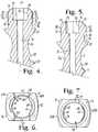
- FIG. 4is an enlarged and partial cross-sectional view taken along the line 4 - 4 of FIG. 2 .
- FIG. 5is an enlarged and partial cross-sectional view taken along the line 5 - 5 of FIG. 2 .
- FIG. 6is an enlarged top plan view of the receiver of FIG. 1 .
- FIG. 7is an enlarged bottom plan view of the receiver of FIG. 1 .
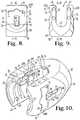
- FIG. 8an enlarged side elevational view of the receiver of FIG. 1 .
- FIG. 9is an enlarged front elevational view of the receiver of FIG. 1 .
- FIG. 10is an enlarged perspective view of the receiver of FIG. 1 .
- FIG. 11is an enlarged cross-sectional view taken along the line 11 - 11 of FIG. 8 .
- FIG. 12is an enlarged cross-sectional view taken along the line 12 - 12 of FIG. 9 .
- FIG. 13is an enlarged cross-sectional view taken along the line 13 - 13 of FIG. 8 .
- FIG. 14is an enlarged perspective view of the retainer of FIG. 1 .
- FIG. 15is an enlarged top plan view of the retainer of FIG. 1 .
- FIG. 16is an enlarged bottom plan view of the retainer of FIG. 1 .
- FIG. 17is an enlarged cross-sectional view taken along the line 17 - 17 of FIG. 15 .
- FIG. 18is an enlarged and partial front elevational view of the shank and retainer of FIG. 1 with portions broken away to show the detail thereof.
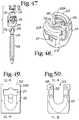
- FIG. 19is an enlarged top plan view of the insert of FIG. 1 .
- FIG. 20is an enlarged bottom plan view of the insert of FIG. 1 .
- FIG. 21is an enlarged perspective view of the insert of FIG. 1 .
- FIG. 22is an enlarged side elevational view of the insert of FIG. 1 .
- FIG. 23is an enlarged front elevational view of the insert of FIG. 1 .
- FIG. 24is an enlarged cross-sectional view taken along the line 24 - 24 of FIG. 23 .
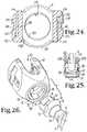
- FIG. 25is a front elevational view of the receiver and retainer of FIG. 1 with portions broken away to show the detail thereof and further showing a stage of assembly of the retainer in phantom.
- FIG. 26is an enlarged and partial perspective view of the receiver, retainer and shank of FIG. 1 shown in an early stage of assembly.
- FIG. 27is an enlarged and partial front elevational view of the receiver, retainer and shank of FIG. 1 shown in a stage of assembly subsequent to that shown in FIG. 26 , with portions broken away to show the detail thereof and further showing cooperating portions of the shank and retainer in phantom.
- FIG. 28is an enlarged and partial front elevational view of the receiver, retainer and shank of FIG. 1 shown in a stage of assembly subsequent to that shown in FIG. 27 , with portions broken away to show the detail thereof and further showing cooperating portions of the shank and retainer in phantom.
- FIG. 29is a reduced front elevational view of the assembled receiver, retainer and shank of FIG. 28 , showing a stage of assembly with the insert of FIG. 1 , shown in a side elevational loading position.
- FIG. 30is an enlarged cross-sectional view of the receiver, retainer and shank taken along the line 30 - 30 of FIG. 29 and further showing the insert of FIG. 29 in top plan view, being shown in a stage of assembly within the receiver.
- FIG. 31is an enlarged cross-sectional view of the receiver, retainer and shank taken along the line 31 - 31 of FIG. 29 and further showing the insert of FIG. 29 in cross-section in a first factory assembled position within the receiver, and also showing in phantom the pair of receiver spring tabs being biased toward the insert.
- FIG. 32is a reduced side elevational view of the receiver, retainer, shank and insert of FIG. 31 with portions broken away to show the detail thereof.
- FIG. 33is a reduced side elevational view, with portions broken away, similar to FIG. 32 , further showing the shank pivoted at an angle with respect to the receiver.
- FIG. 34 ais an enlarged and partial rear elevational view of the assembly of FIG. 32 with portions broken away to show the detail thereof, the insert being shown in the factory assembled position.
- FIG. 34 bis an enlarged and partial rear elevational view of the assembly of FIG. 33 with portions broken away to show the detail thereof, the insert being shown in a subsequent second or locked position with respect to the receiver.
- FIG. 35is a top plan view of the assembly of FIG. 34 , with portions broken away to show the detail thereof and further shown with the rod of FIG. 1 , the insert being pressable downwardly into the second or locked position by the rod.
- FIG. 36is an enlarged and partial side elevational view of the assembly of FIG. 35 , further showing the closure top of FIG. 1 in a stage of assembly with the receiver with portions broken away to show the detail thereof.
- FIG. 37is an enlarged and partial side elevational view of the assembly of FIG. 36 with portions broken away to show the detail thereof and showing the closure top engaging the rod.
- FIG. 38is an enlarged and partial cross-sectional view taken along the line 38 - 38 of FIG. 37 .
- FIG. 39is an enlarged and partial, partially exploded perspective view of the assembled receiver, shank, retainer and insert of FIGS. 32-34 further shown with an alternative deformable rod and an alternative closure top.
- FIG. 40is a partial side elevational view of the assembly of FIG. 39 , shown fully assembled and with portions broken away to show the detail thereof.
- FIG. 41is an enlarged and partial cross-sectional view taken along the line 41 - 41 of FIG. 40 .
- FIG. 42is a reduced and partial perspective view showing the assembled receiver, shank, retainer and insert of FIGS. 32-34 with a cord, first and second spacers located on either side of the receiver, a threaded connecter, a rod and a closure top configured for slidable engagement with the cord.
- FIG. 43is a perspective view of the cord and connector of FIG. 42 with portions broken away to show the detail thereof.
- FIG. 44is an enlarged and partial cross-sectional view taken along the line 44 - 44 of FIG. 42 .
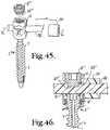
- FIG. 45is a reduced and partial, partially exploded view, showing the assembled receiver, shank, retainer and insert of FIGS. 32-34 with a cord, a spacer and a closure top configured for fixed engagement with the cord.
- FIG. 46is an enlarged and partial cross-sectional view, taken along the line 46 - 46 of FIG. 45 and showing the spacer and closure top in an assembled position.
- FIG. 47is an exploded perspective view of an alternative embodiment of a polyaxial bone screw assembly according to the present invention including a shank, a receiver, a retainer and a compression insert.
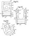
- FIG. 48is an enlarged perspective view of the receiver of FIG. 47 .
- FIG. 49is an enlarged side elevational view of the receiver of FIG. 47 .
- FIG. 50is an enlarged front elevational view of the receiver of FIG. 47 .
- FIG. 51is an enlarged cross-sectional view taken along the line 51 - 51 of FIG. 50 .
- FIG. 52is an enlarged cross-sectional view taken along the line 52 - 52 of FIG. 49 .
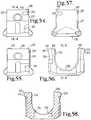
- FIG. 53is an enlarged perspective view of the insert of FIG. 47 .
- FIG. 54is an enlarged side elevational view of the insert of FIG. 47 .
- FIG. 55is an enlarged side elevational view of the insert of FIG. 47 opposite to that shown in FIG. 54 .
- FIG. 56is an enlarged front elevational view of the insert of FIG. 47 .
- FIG. 57is a cross-sectional view taken along the line 57 - 57 of FIG. 56 .
- FIG. 58is a cross-sectional view taken along the line 58 - 58 of FIG. 54 .
- FIG. 59is an enlarged and partial front elevational view of the assembled receiver, retainer and shank of FIG. 47 , shown in exploded view with the insert of FIG. 47 , the insert being in a side elevational loading position.
- FIG. 60is an enlarged top plan view of the assembled receiver, retainer and shank of FIG. 47 , further showing the insert of FIG. 47 in top plan view, being shown in a stage of assembly within the receiver.
- FIG. 61is an enlarged and partial perspective view of the assembled receiver, retainer, shank and insert of FIG. 47 with a portion of the receiver broken away to show the detail thereof.
- FIG. 62is a reduced and partial cross-sectional view taken along the line 62 - 62 of FIG. 61 .
- FIG. 63is a partial cross-sectional view taken along the line 63 - 63 of FIG. 62 .
- FIG. 64is an enlarged and partial front elevational view of the assembly of FIG. 61 , with portions broken away to show the detail of an initial surface engagement between the insert and receiver.
- FIG. 65is an enlarged and partial perspective view of the assembly of FIG. 47 shown assembled with a deformable rod and a closure top.
- FIG. 66is an enlarged and partial front elevational view of the assembly of FIG. 65 with portions broken away to show the detail thereof.
- FIG. 67is an enlarged and partial cross-sectional view taken along the line 67 - 67 of FIG. 65 .
- the reference number 1generally represents a polyaxial bone screw apparatus or assembly according to the present invention.
- the assembly 1includes a shank 4 , that further includes a body 6 integral with an upwardly extending upper portion or capture structure 8 ; a receiver 10 ; a retainer structure 12 and a compression or pressure insert 14 .
- the shank 4 , receiver 10 , retainer 12 and compression insert 14are typically factory assembled prior to implantation of the shank body 6 into a vertebra 13 , as will be described in greater detail below.
- a closure structure 18 of the inventionfor capturing a longitudinal member, for example, a rod 21 which in turn engages the compression insert 14 that presses against the shank upper portion 8 into fixed frictional contact with the retainer 12 , so as to capture, and fix the longitudinal connecting member 21 within the receiver 10 and thus fix the member 21 relative to the vertebra 13 .
- the illustrated rod 21is hard, stiff, non-elastic and cylindrical, having an outer cylindrical surface 22 . It is foreseen (and also will be described with respect to other embodiments) that the rod 21 may be of a different stiffness, elastic, deformable and/or of a different cross-sectional geometry.
- the receiver 10 and the shank 4cooperate in such a manner that the receiver 10 and the shank 4 can be secured at any of a plurality of angles, articulations or rotational alignments relative to one another and within a selected range of angles both from side to side and from front to rear, to enable flexible or articulated engagement of the receiver 10 with the shank 4 until both are locked or fixed relative to each other near the end of an implantation procedure.
- the assemblyis advantageously configured and factory assembled to provide a surgeon with a bone anchor exhibiting sufficient frictional engagement between the compression insert and the shank upper portion that the shank is positionable to a desired angle with respect to the receiver during and after implantation if the shank and prior to locking of the polyaxial mechanism with the closure structure.
- the factory supplied assemblyincludes a shank that is not floppy or loose with respect to the receiver, allowing greater ease in handling and manipulation during the surgical process. Locking of the insert onto the shank upper portion may also be performed prior to locking with the closure top.
- inserts according to the inventionare advantageously configured to allow for a squeeze release to easily provide for repositioning of the angle of the bone screw shank, as will be described in greater detail below.
- the shank 4is elongate, with the shank body 6 having a helically wound bone implantable thread 24 (single or dual lead thread form) extending from near a neck 26 located adjacent to the upper portion or capture structure 8 , to a tip 28 of the body 6 and extending radially outwardly therefrom.
- the body 6utilizing the thread 24 for gripping and advancement is implanted into the vertebra 13 leading with the tip 28 and driven down into the vertebra with an installation or driving tool (not shown), so as to be implanted in the vertebra to near the neck 26 , as more fully described in the paragraphs below.
- the shank 4has an elongate axis of rotation generally identified by the reference letter A.
- the neck 26extends axially upward from the shank body 6 .
- the neck 26may be of the same or is typically of a slightly reduced radius as compared to an adjacent upper end or top 32 of the body 6 where the thread 24 terminates.
- the shank upper portion 8Further extending axially and outwardly from the neck 26 is the shank upper portion 8 that provides a connective or capture apparatus disposed at a distance from the upper end 32 and thus at a distance from the vertebra 13 when the body 6 is implanted in such vertebra.
- the shank upper portion 8is configured for a pivotable connection between the shank 4 (with attached retainer 12 ) and the receiver 10 prior to fixing of the shank 4 in a desired position with respect to the receiver 10 .
- the shank upper portion 8has an outer, convex and substantially spherical lower surface 34 that extends outwardly and upwardly from the neck 26 and terminates at a substantially planar ledge or shelf 36 that is annular and disposed perpendicular to the shank axis A.
- the shelf 36is sized and shaped to receive and seat the retainer 14 at a bottom surface thereof as will be described in greater detail below.
- the spherical lower surface 34has an outer radius that is the same or substantially similar to an outer radius of the retainer 12 as will be described in greater detail below, the surface 34 as well as the retainer 12 outer surface participating in the ball and socket joint formed by the shank 4 and attached retainer 12 within the partially spherical surface defining an inner cavity of the receiver 10 .
- Extending upwardly from the ledge 36is a cylindrical surface 38 , the surface 38 having a radius that is smaller than the radius of the lower spherical surface 34 .
- Extending substantially radially outwardly from the cylindrical surface 38are three evenly spaced cam projections or lugs 40 , each with a lower surface or ledge 41 that faces toward the ledge 36 and is disposed at a slight angle with respect thereto.
- the lower ledge 36 , cylindrical surface 38 and upper ledges 41cooperate to capture and fix the retainer 12 to the shank upper portion 8 , prohibiting movement of the retainer 12 along the axis A once the retainer 12 is located between the ledges 36 and 41 .
- one, two, three or more cam projections 40may be disposed about the cylindrical surface 38 .
- Each of the projections 40further include an outer substantially cylindrical surface 42 bounded by opposed side surfaces 43 .
- a partially spherical or domed top surface 44partially defines each of the projections 40 , terminating at the projection surfaces 42 and the cylindrical surface 38 located between each of the cam projections 40 .
- the spherical surface 44has an outer radius configured for sliding cooperation and ultimate frictional mating with a substantially spherical concave surface of the compression insert 14 that has the same or substantially similar radius as the surface 44 .
- the radius of the surface 44is smaller than the radius of the lower spherical surface 34 .
- Located near or adjacent to the surface 44is an annular top surface 46 .
- a counter sunk substantially planar base or seating surface 49partially defines an internal drive feature or imprint 50 .
- the illustrated internal drive feature 50is an aperture formed in the top surface 46 and has a hex shape designed to receive a hex tool (not shown) of an Allen wrench type, into the aperture for rotating and driving the bone screw shank 4 .
- such an internal tool engagement structuremay take a variety of tool-engaging forms and may include one or more apertures of various shapes, such as a pair of spaced apart apertures or a multi-lobular or star-shaped aperture, such as those sold under the trademark TORX, or the like.
- the seat or base 49 of the drive feature 50is disposed perpendicular to the axis A with the drive feature 49 otherwise being coaxial with the axis A.
- a driving toolis received in the internal drive feature 50 , being seated at the base 49 and engaging the six faces of the drive feature 50 for both driving and rotating the shank body 6 into the vertebra 13 , either before the shank 4 is attached to the receiver 10 or after the shank 4 is attached to the receiver 10 , with the shank body 6 being driven into the vertebra 13 with the driving tool extending into the receiver 10 .
- the shank 4 shown in the drawingsis cannulated, having a small central bore 51 extending an entire length of the shank 4 along the axis A.
- the bore 50is defined by an inner cylindrical wall of the shank 4 and has a circular opening at the shank tip 28 and an upper opening communicating with the internal drive 50 at the surface 49 .
- the bore 51is coaxial with the threaded body 6 and the upper portion 8 .
- the bore 51provides a passage through the shank 4 interior for a length of wire (not shown) inserted into the vertebra 13 prior to the insertion of the shank body 6 , the wire providing a guide for insertion of the shank body 6 into the vertebra 13 .
- the threaded shank body 6may be coated, perforated, made porous or otherwise treated.
- the treatmentmay include, but is not limited to a plasma spray coating or other type of coating of a metal or, for example, a calcium phosphate; or a roughening, perforation or indentation in the shank surface, such as by sputtering, sand blasting or acid etching, that allows for bony ingrowth or ongrowth.
- Certain metal coatingsact as a scaffold for bone ingrowth.
- Bio-ceramic calcium phosphate coatingsinclude, but are not limited to: alpha-tri-calcium phosphate and beta-tri-calcium phosphate (Ca 3 (PO 4 ) 2 , tetra-calcium phosphate (Ca 4 P 2 O 9 ), amorphous calcium phosphate and hydroxyapatite (Ca 10 (PO 4 ) 6 (OH) 2 ).
- Coating with hydroxyapatitefor example, is desirable as hydroxyapatite is chemically similar to bone with respect to mineral content and has been identified as being bioactive and thus not only supportive of bone ingrowth, but actively taking part in bone bonding.
- the receiver 10has a generally U-shaped appearance with a partially discontinuous substantially cylindrical inner and outer profiles.
- the receiver 10has an axis of rotation B that is shown in FIG. 1 as being aligned with and the same as the axis of rotation A of the shank 4 , such orientation being desirable, but not required during assembly of the receiver 10 with the shank 4 .
- the axis Bis typically disposed at an angle with respect to the axis A, as shown, for example, in FIG. 33 .
- the receiver 10includes a partially cylindrical and partially frusto-conical base 58 integral with a pair of opposed upstanding arms 60 A and 60 B, the arms forming a cradle and defining a U-shaped channel 62 between the arms 60 A and B with an upper opening, generally 63 , and a U-shaped lower seat 64 , the channel 62 having a width for operably snugly receiving the rod 21 between the arms 60 A and B.
- Each of the arms 60 A and 60 Bhas an interior surface, generally 66 , that has a cylindrical profile and further includes a partial helically wound guide and advancement structure 68 extending radially inwardly from the surface 66 and located adjacent top surfaces 69 of each of the arms 60 .
- the guide and advancement structure 68is a partial helically wound interlocking flangeform configured to mate under rotation with a similar structure on the closure structure 18 , as described more fully below.
- the guide and advancement structure 68could alternatively be a square-shaped thread, a buttress thread, a reverse angle thread or other thread-like or non-thread-like helically wound discontinuous advancement structure for operably guiding under rotation and advancing the closure structure 18 downward between the arms 60 , as well as eventual torquing when the closure structure 18 abuts against the rod 21 .
- An opposed pair of tool receiving and engaging featuresare formed on outer surfaces 72 of the arms 60 A and 60 B.
- the illustrated features 71are in a T-shape form and include and upper groove or recess 73 running substantially parallel to the respective top surface 69 that does not extend through the respective arm 60 A or 60 B and a connecting transverse, substantially rectangular lower recess or through bore 74 that does extend from each arm outer surface 72 to each interior surface 66 , providing access to laterally extending spring tabs 75 that bias against the pressure insert 14 to prohibit reverse (illustrated as counter-clockwise) rotational movement of the insert about the receiver axis once the insert is loaded in the receiver 10 , as will be described in greater detail below.
- any additional tool receiving and engaging aperturesmay be formed in the receiver outer surfaces and used for holding the receiver 10 during assembly with the shank 4 , the retainer 12 and the insert 14 , during the implantation of the shank body 6 into a vertebra when the shank is pre-assembled with the receiver 10 , and during assembly of the bone anchor assembly 1 with the rod 21 and the closure structure 18 . It is foreseen that tool receiving grooves or apertures may be configured in a variety of shapes and sizes and be disposed at other locations on the receiver arms 60 A and 60 B.
- a discontinuous cylindrical surface 77located below the guide and advancement structure 68 on each of the arms is a discontinuous cylindrical surface 77 , having a diameter approximately the same as a greater diameter of the guide and advancement structure 68 .
- the space under the guide and advancement structure 68 that is defined in part by the cylindrical surface 77forms a run-out area for the closure top 18 .
- the cylindrical surface 77is adjacent to an upper surface or ledge 76 that partially defines the flange form 68 run-out and also serves as an intermediate or temporary abutment feature (along with the cylindrical surface 77 ) for the insert 14 as shown, for example, in FIG.
- Adjacent to and located below the cylindrical surface 77is a discontinuous annular surface 78 that in turn is adjacent to a discontinuous substantially cylindrical surface 80 .
- the surface 80extends from the surface 78 to an annular lip or ledge 81 that is disposed perpendicular to the axis B and extends radially inwardly toward the axis B.
- a portion of the ledge 81is adjacent to and integral with a sloping or curved transition surface 83 that in turn is adjacent to and integral with an upper surface 84 of the respective spring tab 75 .
- Adjacent to the annular lip 81is another partially discontinuous substantially cylindrical surface 86 that partially defines the arms 60 A and 60 B as well as extends into the base 58 .
- the surface 86also partially defines the lower seat 64 of the U-shaped channel 62 .
- An inner surface 88 of the spring tab 75is integral with the surface 86 .
- the surface 86has a diameter smaller than the diameter of the cylindrical surface 80 , but larger than the diameter of the surface 77 ; this diameter feature will come into play with respect to the cooperation between the insert 14 and the receiver inner surfaces 76 , 77 , 78 and 86 as will be described in detail below.
- the surface 86also partially defines an inner cavity, generally 90 , of the base 58 of the receiver 10 , the cavity 90 and the U-shaped channel 62 defining a through bore of the receiver 10 from the top surface 69 to a bottom surface 92 thereof.
- a substantially conical surface 94is adjacent to the cylindrical surface 86 and terminates at a radiused or spherical seating surface 96 .
- the surface 94 as well as portions of the surface 86may be partially spherical or otherwise curved in some embodiments of the invention.
- the surface 96is sized and shaped for slidably mating with the retainer structure 12 and ultimately frictionally mating therewith as will be described in greater detail below.
- the spherical seating surface 96is adjacent a flared surface or as shown, a series of beveled surfaces that provide a neck 97 that forms a bottom opening, generally 98 , to the cavity 90 at the receiver bottom surface 92 .
- the neck 97is sized and shaped to be smaller than an outer radial dimension of the retainer 12 when the retainer 12 is fixed to the shank upper portion 8 , so as to form a restriction to prevent the structure 12 and attached shank portion 8 from passing through the cavity 90 and out the lower exterior 92 of the receiver 10 during operation thereof.
- the cooperating compression insert 14includes a cooperating structure 104 that extends outwardly from each arm thereof that abuts against the respective abutment wall 102 of each of the receiver arms, providing a centering stop or block when the insert 14 is rotated into place in a clockwise manner as will be described below.
- each spring tab 75further includes a bottom surface 108 and an end surface 109 .
- the surface 109is adjacent to and extends between the surfaces 108 and 84 , the end surface 109 running substantially parallel to the receiver axis B.
- the end surfaces 109 of the opposing spring tabs 75generally face in opposite directions. As described more fully below and shown, for example, in FIG. 31 , during assembly, the tabs 75 are pressed radially inwardly to engage the insert 14 and prohibit counter-clockwise motion of the insert 14 with respect to the receiver 10 .
- the retainer 12 that operates to capture the shank upper portion 8 within the receiver 10has a central axis that is operationally the same as the axis A associated with the shank 4 when the shank upper portion 8 and the retainer 12 are installed within the receiver 10 .
- the retainer 12is typically made from a hard material, that also may be resilient, such as stainless steel or titanium alloy, for embodiments (not shown) having a slit or slot that would allow for top or bottom loading, so that the retainer 12 may be contracted or expanded during assembly.
- the retainer structure 12has a central bore, generally 110 , that passes entirely through the retainer structure 12 from a top surface 112 to a bottom surface 114 thereof.
- the bottom surface 114is substantially planar and disposed perpendicular to the axis A when the retainer is fixed to the shank 4 with the surface 114 abutting the shank surface 36 as shown, for example, in FIG. 18 .
- the top surface 112is disposed at an angle with respect to the axis A when the retainer 12 is fixed to the shank 4 , the surface 112 sloping radially downwardly to provide space and clearance between the retainer 12 and the insert 14 when the assembly 1 is fully assembled and placed at any angle of inclination of the shank 4 with respect to the receiver 10 .
- a first inner cylindrical surface 116defines a substantial portion of the bore 110 .
- the cylindrical surface 116is sized and shaped to be slidingly received about the cylindrical surface portion 38 of the shank upper portion 8 .
- Extending inwardly radially from the surface 116are three evenly spaced cam projections or shelves 118 sized and shaped to cooperate with the cam projections 40 of the shank upper portion 8 for fixing the retainer 12 to the shank upper portion 8 .
- the cam shelves 118extend from at or near the retainer bottom 114 to a location spaced from the retainer top 112 .
- the cam shelves 118are sized and shaped to provide direct mating support with each shank projection 40 .
- the cam shelves 118are also spaced from the top surface 112 to provide adequate space for loading rotation and placement of the cam projections 40 of the shank upper portion 8 with respect to the retainer 12 during assembly within the receiver 10 of the bone screw 1 .
- Each of the illustrated cam shelves 118includes an upper, sloping or slanted seating surface 120 and an opposed bottom surface 122 that is flush and integral with the bottom surface 114 of the retainer 12 .
- the illustrated camming seating surfaces 120are each disposed about midway between the top 112 and the bottom 114 of the retainer 12 , but may be located slightly higher or lower along the surface 116 .
- Each camming shelf 118further includes opposed side surfaces 124 and 125 running from the bottom surface 114 to the seating surface 120 .
- Each of the surfaces 124 and 125are curved and substantially concave.
- Each shelfincludes an inner cylindrical surface 126 sized and shaped to slidingly mate with the surfaces 42 of the cam projections 40 of the shank upper portion 8 .
- the sloping seating surfaces 120are sized to receive the lugs or projections 40 at the surfaces 41 thereof, with the surfaces 36 and 41 of the shank upper portion forming a cam track between which each camming shelf 118 slides and is captured and frictionally fixed.
- a degree of inclination of the surface 120substantially matches a degree of inclination of the bottom surface 41 of the lug 40 . In the illustrated embodiment, the degree of inclination is about three degrees, but it is foreseen that it may be more or less than that illustrated.
- one or both the ramped surfaces 41 and 120include a roughening, ridges or some other treatment to further aid frictional locking of the retainer 12 with respect to each lug 40 .
- fixing engagement between the lugs 40 and the shelves 122may be enhanced by a weld or adhesive.
- the illustrated camming shelves 118are slightly wider than the shank projections 40 at the side surfaces 124 and 125 so as to advantageously accommodate a spot weld or other fixing or adhering structure or substance.
- the retainer 12also has a radially outer partially spherically shaped surface 129 sized and shaped to mate with the partial spherical shaped seating surface 96 of the receiver 10 .
- the surface 129includes an outer radius that is larger than a radius of the lower opening 98 of the receiver 10 , thereby prohibiting the retainer 12 and the shank upper portion 8 from passing through the opening 98 once the retainer 12 is fixed to the shank upper portion 8 within the receiver cavity 90 .
- the outer partially spherically shaped surface 129may be a high friction surface such as a knurled surface or the like.
- the compression or pressure insert 14is illustrated that is sized and shaped to be received by and down-loaded into the receiver 10 through the channel opening 66 as illustrated in FIGS. 29-31 .
- the compression insert 14has an operational central axis that is the same as the central axis B of the receiver 10 .
- the compression insert 14has a central channel or through bore, generally 130 , substantially defined by an inner substantially cylindrical surface 131 coaxial with an inner partially spherical surface 132 .
- the compression insert 14 through boreis sized and shaped to receive a driving tool (not shown) therethrough that engages the shank drive feature 50 when the shank body 6 is driven into bone with the receiver 10 attached.
- the surface 132is sized and shaped to slidingly receive and ultimately frictionally engage the substantially spherical or domed surface 44 of the shank upper portion 8 such that the surface 44 initially frictionally slidingly and pivotally mates with the spherical surface 132 to create a ball-and-socket type joint.
- the surfaces 44 and/or 132may include a roughening or surface finish to aid in frictional contact between them once a desired angle of articulation of the shank 4 with respect to the receiver 10 is reached.
- the compression insert 14includes a substantially cylindrical base body 134 integral with a pair of upstanding arms 135 .
- the bore 130is disposed primarily within the base body 134 and communicates with a generally U-shaped through channel 136 that is defined by the upstanding arms 135 .
- the channel 136has a lower seat 138 sized and shaped to closely, snugly engage the rod 21 . It is foreseen that an alternative embodiment may be configured to include planar holding surfaces that closely hold a square or rectangular bar as well as hold a cylindrical rod-shaped or corded longitudinal connecting member.
- the arms 135 disposed on either side of the channel 136extend outwardly and upwardly from the body 134 .
- the arms 135are sized and configured for ultimate placement near the run-out below the receiver guide and advancement structure 68 . It is foreseen that in some embodiments of the invention, the arms may be extended and the closure top configured such the arms ultimately directly engage the closure top for locking of the polyaxial mechanism.
- the arms 135include top surfaces 140 that are ultimately positioned in spaced relation with the closure top 18 , so that the closure top 18 frictionally engages and holds the rod 21 , pressing the rod 21 downwardly against the seating surface 138 , the insert 14 in turn pressing against the domed top 44 of the shank 4 to lock the polyaxial mechanism of the bone screw assembly 1 .
- the illustrated insert 14further includes features that allow for a non-floppy frictional fit between the insert and the shank 4 during assembly and also for a locking of the insert 14 with respect to the shank 4 prior to locking down of the closure top 18 .
- These featuresinclude a key-hole like through slot 144 disposed within each arm 135 running substantially vertically from the top surface 140 and through the base body 134 .
- each arm 135includes at least one radially projected upper portion 146 with an outer partially cylindrical surface 147 for engaging with the receiver 10 as will be described more fully below. It is foreseen that inserts 14 according to the invention may have at least one and up to a plurality of such portions 146 .
- the illustrated slots 144open along opposed side surfaces 150 of the arms, the side surfaces 150 each also defining a portion of one of the projected upper portions 146 .
- Each slot 144terminates at a cylindrical through bore 152 that also runs from the top surface 140 through the base body 134 and out a base surface 153 , the bore 152 being spaced from inner and outer surfaces of each of the arms 135 .
- Each slot 144separates each arm 135 into an inner arm portion 154 and an outer arm portion 155 that includes the respective projected upper portion 146 , the portions 155 being compressible towards the portions 154 during assembly of the insert 14 within the receiver 10 as will be described in greater detail below.
- Each arm 135further includes inner planar walls 158 and inner sloping lower surfaces 159 .
- Each outer arm portion 155further includes a generally vertically extending recess or partial aperture 160 sized and shaped to receive holding tabs 75 , or, in some embodiments of the invention, crimped material from the receiver.
- the pressure insert body 134 located between the arms 135has an outer diameter slightly smaller than a diameter between crests of the guide and advancement structure 68 of the receiver 10 allowing for top loading of the compression insert 14 into the receiver opening 63 , with the arms 135 of the insert 14 being located between the receiver arms 60 A and 60 B during insertion of the insert 14 into the receiver 10 .
- the insert 14is rotated into place about the receiver axis until the arms 135 are directly below the guide and advancement structure 68 as will be described in greater detail below.
- a tool(not shown) may be inserted into the receiver apertures to press the tabs 75 into the insert recesses 160 .
- assembly of the shank 4 with the retainer 12 within the receiver 10 , followed by insertion of the lower compression insert 14 into the receiver 10are assembly steps typically performed at the factory, advantageously providing a surgeon with a polyaxial bone screw with the lower insert 14 already held in alignment with the receiver 10 and providing a non-floppy, but pivotable shank ready for insertion into a vertebra.
- the compression or pressure insert 14ultimately seats exclusively on the surface 44 of the shank upper portion 8 , with the base surface 153 sloping upwardly and away from the shank upper portion 8 , providing clearance between the retainer 12 and the insert 14 during pivoting of the shank 4 with respect to the receiver 10 .
- the assemblymay be configured so that the insert 14 extends at least partially into the receiver U-shaped channel 62 .
- the illustrated elongate rod or longitudinal connecting member 21can be any of a variety of implants utilized in reconstructive spinal surgery, but is typically a cylindrical, elongate structure having the outer substantially smooth, cylindrical surface 22 of uniform diameter.
- the rod 21may be made from a variety of metals, metal alloys and deformable and less compressible plastics, including, but not limited to rods made of elastomeric, polyetheretherketone (PEEK) and other types of materials.
- PEEKpolyetheretherketone
- Longitudinal connecting members for use with the assembly 1may take a variety of shapes, including but not limited to rods or bars of oval, rectangular or other curved or polygonal cross-section.
- the shape of the insert 14may be modified so as to closely hold, and if desired, fix or slidingly capture the longitudinal connecting member to the assembly 1 .
- Some embodiments of the assembly 1may also be used with a tensioned cord.
- a tensioned cordmay be made from a variety of materials, including polyester or other plastic fibers, strands or threads, such as polyethylene-terephthalate.
- the longitudinal connectormay be a component of a longer overall dynamic stabilization connecting member, with cylindrical or bar-shaped portions sized and shaped for being received by the compression insert 14 of the receiver having a U-shaped channel (or rectangular- or other-shaped channel) for closely receiving the longitudinal connecting member.
- the longitudinal connecting membermay be integral or otherwise fixed to a bendable or damping component that is sized and shaped to be located between adjacent pairs of bone screw assemblies 1 , for example.
- a damping component or bumpermay be attached to the longitudinal connecting member at one or both sides of the bone screw assembly 1 .
- a rod or bar (or rod or bar component) of a longitudinal connecting membermay be made of a variety of materials ranging from deformable plastics to hard metals, depending upon the desired application.
- bars and rods of the inventionmay be made of materials including, but not limited to metal and metal alloys including but not limited to stainless steel, titanium, titanium alloys and cobalt chrome; or other suitable materials, including plastic polymers such as polyetheretherketone (PEEK), ultra-high-molecular weight-polyethylene (UHMWP), polyurethanes and composites, including composites containing carbon fiber, natural or synthetic elastomers such as polyisoprene (natural rubber), and synthetic polymers, copolymers, and thermoplastic elastomers, for example, polyurethane elastomers such as polycarbonate-urethane elastomers.
- plastic polymerssuch as polyetheretherketone (PEEK), ultra-high-molecular weight-polyethylene (UHMWP), polyurethanes and composites, including composites containing carbon fiber, natural or synthetic elastomers such as polyisoprene (natural rubber), and synthetic polymers, copolymers, and thermoplastic elastomers
- the closure structure or closure top 18 shown with the assembly 1is rotatably received between the spaced arms 60 A and 60 B.
- the closure 18can be any of a variety of different types of closure structures for use in conjunction with the present invention with suitable mating structure on the upstanding arms 60 A and 60 B.
- the closure topcould be a twist-in or slide-in closure structure.
- the illustrated closure structure 18is substantially cylindrical and includes an outer helically wound guide and advancement structure 162 in the form of a flange form that operably joins with the guide and advancement structure 68 disposed on the arms 60 A and 60 B of the receiver 10 .
- the flange form utilized in accordance with the present inventionmay take a variety of forms, including those described in Applicant's U.S. Pat. No. 6,726,689, which is incorporated herein by reference. It is also foreseen that according to the invention the closure structure guide and advancement structure could alternatively be a buttress thread, a square thread, a reverse angle thread or other thread like or non-thread like helically wound advancement structure for operably guiding under rotation and advancing the closure structure 18 downward between the arms 60 A and 60 B and having such a nature as to resist splaying of the arms when the closure structure 18 is advanced into the U-shaped channel 62 .
- the closure structure 18may alternatively include a break-off head designed to allow such a head to break from a base of the closure at a preselected torque, for example, 70 to 140 inch pounds.
- a closure structurewould also include a base having an internal drive to be used for closure removal.
- a base or bottom surface 168 of the closureis planar and further includes a point 169 and a rim 170 for engagement and penetration into the surface 22 of the rod 21 in certain embodiments of the invention.
- the closure top 18may further include a cannulation through bore (not shown) extending along a central axis thereof and through the top and bottom surfaces thereof. Such a through bore provides a passage through the closure 18 interior for a length of wire (not shown) inserted therein to provide a guide for insertion of the closure top into the receiver arms 60 A and B.
- the shank 4 , receiver 10 , the retainer 12 and the compression insert 14are assembled at a factory setting that includes tooling for holding and alignment of the component pieces and compressing arm portions of the insert 14 .
- Assembly of the shank 4 , the receiver 10 , the retainer 12 and the compression insert 14is shown in FIGS. 25-34 b .
- the ring-like retainer 12is typically first inserted or top-loaded through the opening 63 with the top 112 and bottom 114 surfaces aligned with the receiver axis B within the receiver U-shaped channel 62 and then into the cavity 90 to dispose the structure 12 within the receiver base 58 .
- the retainer structure 12is rotated approximately 90 degrees so as to be coaxial with the receiver 10 and then seated in sliding engagement with the seating surface 96 of the receiver 10 .
- the shank capture structure 8is then inserted or bottom-loaded into the receiver 10 through the opening 98 .
- the retainer structure 12now disposed in the receiver 10 is coaxially aligned with the shank capture structure 8 so that the camming lugs 40 are received by the retainer 12 and moved between and through the camming shelves 118 until the bottom surface 114 of the retainer 12 engages the surface 36 of the shank upper portion 8 .
- the retainer 12is then partially rotated about the axis A of the shank 4 until the retainer shelves 118 are received in the cam track formed by the shank surface 36 and the shank projection camming or sloped surface 41 .
- the shank projection bottom surface 41frictionally engages the ramped surface 120 of the camming shelf 118 , creating a press fit between the surfaces and frictionally locking the retainer 12 between the lugs or projections 40 and the shank upper portion 8 seat 36 , the retainer 12 now in fixed coaxial relationship with the shank 4 .
- both the shank 4 and the retainer 12are in loose, rotatable and swivelable engagement with the receiver 10 , while the shank upper portion 8 and the lower aperture or neck 97 of the receiver 10 cooperate to maintain the shank body 6 in swivelable relation with the receiver 10 .
- Only the retainer 12is in slidable engagement with the receiver spherical seating surface 96 .
- the shank upper end 44 and the shank body 6are in spaced relation with the receiver 10 .
- the shank body 6can be rotated through a substantial angular rotation relative to the receiver 10 , both from side to side and from front to rear so as to substantially provide a universal or ball joint.
- the compression insert 14is downloaded into the receiver 10 through the upper opening 63 with the insert bottom surface 153 facing the receiver arm top surfaces 69 and the insert arms 135 located between the receiver arms 60 A and 60 B.
- the insert 14is lowered toward the channel seat 64 until the insert 14 is located below the surface run-put feature 76 of the guide and advancement structure 68 and the spherical surface 132 engages the domed surface 44 of the shank 4 .
- the insert 14is rotated in a clockwise manner as indicated by the arrow CL in FIG. 30 until the stop structures 104 of the insert 14 abut against the wall 102 of the recess stop 100 located on the receiver arms 60 A and 60 B (see FIG. 31 ).
- the upper projections 146also engage the receiver cylindrical surface 77 , compressing the outer arm portions 155 toward the inner arm portions 154 to provide a slidable friction fit between the insert 14 and the receiver 10 at the surface 77 .
- the insert 14engages the shank upper portion 8 at the surface 44 in a manner that allows for pivoting of the shank with respect to the receiver 10 with effort, thus a frictional fit that advantageously allows for setting a desired angle of the shank 4 with respect to the receiver 10 , that may be adjusted, but is not otherwise floppy or loosely movable.
- the surface 76 of the receiverprohibits the insert 14 from moving upwardly away from the shank surface 44 .
- FIG. 34 abest illustrates the position of the insert 14 with respect to the receiver 10 prior to implanting of the shank body 6 into the vertebra 13 .
- the assembly 1 made up of the assembled shank 4 , receiver 10 , retainer 12 and compression insert 14is screwed into a bone, such as the vertebra 13 , by rotation of the shank 4 using a suitable driving tool (not shown) that operably drives and rotates the shank body 6 by engagement thereof at the internal drive 50 .
- the vertebra 13may be pre-drilled to minimize stressing the bone and have a guide wire (not shown) inserted therein to provide a guide for the placement and angle of the shank 4 with respect to the vertebra.
- a further tap holemay be made using a tap with the guide wire as a guide.
- the bone screw assemblyis threaded onto the guide wire utilizing the cannulation bore 51 by first threading the wire into the opening at the bottom 28 and then out of the top opening at the drive feature 50 .
- the shank 4is then driven into the vertebra using the wire as a placement guide.
- the shank and other bone screw assembly parts, the rod 21 (also having a central lumen in some embodiments) and the closure top 18 (also with a central bore)can be inserted in a percutaneous or minimally invasive surgical manner, utilizing guide wires.
- the receiver 10may be articulated to a desired position with respect to the shank 4 as shown, for example, in FIG. 33 .
- the insert 14may be placed into a fixed or locked position with respect to the receiver 10 by pressing the insert 14 axially downwardly against the shank top surface 44 . This may be done by pressing the rod 35 into the insert 14 as shown in FIG. 35 or by tooling (not shown) that lowers the insert 14 to a location out of engagement with the cylindrical surface 77 as shown in FIG. 34 b .
- the outer arm portion 155resiliently moves or springs back toward a neutral position, and such action puts the outer arm portion 155 into a full, frictional engagement with the lower receiver surface 86 , locking the insert 14 against the shank upper portion 8 , the shank 4 no longer movable with respect to the receiver 10 .
- the surgeonmay make other adjustments in the rod 21 or other longitudinal connection assembly components with confidence that the shank 4 and the receiver 10 of the assembly 1 is fully locked into a desired angular position.
- toolsmay be inserted into the receiver aperture 74 and the insert outer arm portion 155 may be compressed inwardly radially toward the axis B, loosening the insert 14 from the receiver cylindrical surface 86 , and thus loosening engagement between the insert surface 132 and the shank upper portion surface 44 .
- the closure structure 18rotates and moves downwardly into the respective receiver 10 , the point 169 and rim 170 engage and penetrate the rod surface 22 , the closure structure 18 pressing downwardly against and biasing the rod 21 into engagement with the insert 14 that urges the shank upper portion 8 toward the retainer 12 and into locking engagement therewith, the retainer 12 frictionally abutting the surface 96 .
- about 80 to about 120 inch pounds of torque on the closure topmay be applied for fixing the bone screw shank 6 with respect to the receiver 10 .
- the assembly 1is illustrated with an alternative rod 21 ′ and an alternative closure top 18 ′, thus the resulting assembly is identified as an assembly 1 ′.
- the rod 21 ′is substantially similar to the rod 21 in size and shape.
- the rod 21 ′is made from a deformable material, illustrated as a plastic material.
- the closure top 18 ′is substantially similar to the top 18 with the exception that the top 18 ′ includes an outer annular flat bottom surface 168 ′ adjacent to an otherwise curved bottom that further includes a central rounded point or projection 169 ′ located on a spherical or domed shape surface 170 ′. As best shown in FIG.
- the assembly 1 of the inventionis shown with alternative closure tops 18 ′′ and 18 ′′′ as well as with a cord/cord coupler combination 180 and a cord 184 .
- the assembly 1 ′′is identical to the assembly 1 previously described herein with the exception of the rod 21 is replaced by the cord/cord coupler combination 180 and the closure 18 is replaced by the closure 18 ′′.
- the cord/cord coupler combination 180further includes a cord 184 with a lip 185 that is fixed within a coupler 187 that further includes inner threads 189 for attaching to a hard rod 190 .
- the illustrated assemblyfurther includes spacers 192 and 193 that may be compressible or not.
- the closure top 18 ′′includes a planar bottom surface 168 ′′ sized and shaped to abut against the insert 14 top surface 140 as illustrated in FIG. 41 with respect to the assembly 1 ′, providing independent locking of the shank 4 with respect to the receiver 10 .
- sufficient locking of the bone screw 1 ′′may be provided by the insert 14 outer arm portions pressing against the cylindrical surface 86 of the receiver 10 as illustrated in FIG. 34 b with respect to the assembly 1 .
- the bottom surface 168 ′′ of the closure 18 ′′allows for the cord 180 to slide with respect to the receiver 10 , the cord being fixed to the rod 190 at the coupler 187 .
- the cord 180is also fixed to another bone screw 1 (not shown) or fixed to a fixing or blocking structure (not shown) engaging the cord 184 at a location opposite the spacer 193 or other cooperating bone screws.
- the assembly 1 ′′′is identical to the assembly 1 with the exception that the rod 21 is replaced by the cord 184 and the closure 18 is replaced by the closure 18 ′′′.
- the closure 18 ′′′includes a planar bottom rim 168 ′′′ as well as an extension or protrusion 169 ′′′ that engages and penetrates the cord 184 , holding the cord 184 in fixed engagement with the bone screw assembly 1 ′′′.
- a spacer 194that may be compressible or not.
- the cord 184is preferably in tension.
- the assembly 1 ′′′may be used in combination with the assembly 1 ′′ shown in FIGS. 42-44 with the spacer 193 located between the bone screw assemblies 1 ′′ and 1 ′′′, the cord 180 replacing the cord 184 .
- the cord 180would be held in tension between the coupler 187 and the bone screw closure 169 ′′′.
- the assembly 201includes a shank 204 having a shank body 206 and an upper portion 208 , a receiver 210 , a cam retainer 212 and a compression or pressure insert 214 .
- the assembly 201is substantially similar to the assembly 1 with the exception of certain features of the receiver 210 and the insert 214 as will be described in detail below.
- the receiver 214includes a top surface, rather than an outer or side surface that frictionally engages the receiver 210 to place the insert 214 into frictional engagement with the shank upper portion 208 prior to placement of a rod 21 or other longitudinal connecting member into the receiver 210 .
- the insert 214includes an outer surface that engages a cylindrical surface of the receiver 210 to place the insert 214 into locking engagement with the shank upper portion 208 prior to ultimate locking with a closure top (not shown) that may be the closure top 18 , 18 ′, 18 ′′ or 18 ′′ previously described herein with respect to the assemblies 1 , 1 ′, 1 ′′ and 1 ′′′, the closure top chosen based upon the type of rod, cord or other longitudinal connecting member being placed within the receiver 210 . Similar to the insert 14 , the insert 214 may be compressed or squeezed to release locking engagement with the receiver 210 and the shank upper portion 208 . The insert 214 advantageously provides such a release-able locking engagement without the key hole slot feature of the insert 14 as will be described in greater detail below.
- the shank 204is identical or substantially similar to the shank 4 of the assembly 1 and therefore, among other things, includes a spherical surface 234 , a retainer seat 236 , three cam lugs or projections 240 , a domed top 244 , and an internal drive feature 250 , the same or similar to the respective spherical surface 34 , retainer seat 36 , cam lugs 40 , domed top 44 and internal drive 50 previously discussed herein with respect to the shank 4 .
- the retainer 212includes, among other things, a top 312 , bottom 314 , cam shelves 318 and outer spherical surface 329 that are the same or substantially similar to the respective top 112 , bottom 114 , cam shelves 118 and outer spherical surface 129 of the retainer 12 previously described herein with respect to the assembly 1 .
- the shank 204 and the retainer 212are assembled within the receiver 210 in a manner the same or substantially similar to that described previously herein with respect to the shank 4 , retainer 12 and receiver 10 of the assembly 1 .
- a receive cavity, generally 290includes an upper cylindrical or slightly conical surface 294 and a spherical seating surface 296 for sliding and ultimate frictional mating with the retainer spherical surface 329 .
- the receiver 210further includes a lower neck 297 forming an opening 298 at a bottom surface 292 of the receiver 210 .
- the insert 214includes a bore, 330 , an inner cylindrical surface 331 , an inner spherical surface 332 , a substantially cylindrical body 334 , upstanding arms 335 , a u-shaped channel 336 , a channel seat 338 and arm top surfaces 340 substantially similar to the respective bore, 130 , inner cylindrical surface 131 , inner spherical surface 132 , substantially cylindrical body 134 , upstanding arms 135 , u-shaped channel 136 , channel seat 138 and arm top surfaces 140 previously described herein with respect to the insert 14 .
- the insert 214does not include the key-hole slot feature of the insert 214 .
- At least one or both of the top surfaces 240includes an upwardly sloping surface feature 342 spaced from a notch 343 formed in the insert arm 335 .
- the notch 343may be pressed downwardly toward the body 334 .
- FIG. 55illustrates an embodiment wherein both surfaces 240 include the surface feature 342 , the second feature shown in phantom as 342 ′. As best illustrated in FIG.
- the surface 342engages the receiver surface 276 to hold the insert 214 against the shank upper surface 244 after assembly therewith, so that a friction-fit, non-floppy engagement between the insert 214 and the shank top 208 allows for placement of the angle of the shank 204 with respect to the receiver 210 during surgery and prior to the rod or other connecting member being placed in the receiver 210 .
- the arms 335include upper portions 345 that flare outwardly and are sized and shaped to cooperate with the surface 280 of the receiver 210 (see FIG. 64 ) for tight frictional, locking fit between the insert 214 and the shank upper portion 208 when the insert 214 is pushed downwardly toward the receiver base, either by a rod or by a tool. Such locking may be released by a inserting a tool (not shown) in the tool engagement feature 371 and pressing the insert 214 radially inwardly.
- the insert 214is loaded into the receiver 210 in a manner similar to that described above with respect to the insert 14 and the receiver 10 of the assembly 1 .
- the assembly 201is thereafter fitted with a rod 21 or other longitudinal connecting member and a closure top 18 or cooperating top as described above with respect to the assembly 1 .
- the assembly 201is shown with the deformable rod 21 ′ and the closure top 18 ′ previously described herein.
- the resulting assemblyis identified as 210 ′.
- the closure 18 ′presses and locks down upon the insert 214 at the surface 340 , independently locking the assembly 201 when the assembly is used to capture the deformable rod 21 ′. Further independent locking is provided by the insert 214 pressing against the receiver surface 280 .
Landscapes
- Health & Medical Sciences (AREA)
- Orthopedic Medicine & Surgery (AREA)
- Life Sciences & Earth Sciences (AREA)
- Surgery (AREA)
- Neurology (AREA)
- Heart & Thoracic Surgery (AREA)
- Engineering & Computer Science (AREA)
- Biomedical Technology (AREA)
- Nuclear Medicine, Radiotherapy & Molecular Imaging (AREA)
- Medical Informatics (AREA)
- Molecular Biology (AREA)
- Animal Behavior & Ethology (AREA)
- General Health & Medical Sciences (AREA)
- Public Health (AREA)
- Veterinary Medicine (AREA)
- Surgical Instruments (AREA)
Abstract
Description
Claims (29)
Priority Applications (6)
| Application Number | Priority Date | Filing Date | Title |
|---|---|---|---|
| US13/068,506US10792074B2 (en) | 2007-01-22 | 2011-05-12 | Pivotal bone anchor assemly with twist-in-place friction fit insert |
| US17/033,417US11717328B2 (en) | 2007-01-22 | 2020-09-25 | Pivotal bone anchor assembly with twist-in-place insert |
| US18/221,348US12383311B2 (en) | 2010-05-14 | 2023-07-12 | Pivotal bone anchor assembly and method for use thereof |
| US18/359,566US12042185B2 (en) | 2010-05-14 | 2023-07-26 | Pivotal bone anchor assembly with resiliently biased friction fit insert |
| US18/776,707US12329422B2 (en) | 2010-05-14 | 2024-07-18 | Pivotal bone anchor assembly with resiliently axially compressible shank head and rod engaging insert |
| US19/227,292US20250288330A1 (en) | 2010-05-14 | 2025-06-03 | Pivotal bone anchor assembly with resiliently axially-compressible insert |
Applications Claiming Priority (6)
| Application Number | Priority Date | Filing Date | Title |
|---|---|---|---|
| US88164107P | 2007-01-22 | 2007-01-22 | |
| US93136207P | 2007-05-23 | 2007-05-23 | |
| US12/009,130US8257398B2 (en) | 2003-06-18 | 2008-01-16 | Polyaxial bone screw with cam capture |
| US12/154,460US8257396B2 (en) | 2003-06-18 | 2008-05-23 | Polyaxial bone screw with shank-retainer inset capture |
| US39569210P | 2010-05-14 | 2010-05-14 | |
| US13/068,506US10792074B2 (en) | 2007-01-22 | 2011-05-12 | Pivotal bone anchor assemly with twist-in-place friction fit insert |
Related Parent Applications (1)
| Application Number | Title | Priority Date | Filing Date |
|---|---|---|---|
| US12/009,130Continuation-In-PartUS8257398B2 (en) | 2003-06-18 | 2008-01-16 | Polyaxial bone screw with cam capture |
Related Child Applications (1)
| Application Number | Title | Priority Date | Filing Date |
|---|---|---|---|
| US17/033,417ContinuationUS11717328B2 (en) | 2007-01-22 | 2020-09-25 | Pivotal bone anchor assembly with twist-in-place insert |
Publications (3)
| Publication Number | Publication Date |
|---|---|
| US20110282399A1 US20110282399A1 (en) | 2011-11-17 |
| US20130218212A9 US20130218212A9 (en) | 2013-08-22 |
| US10792074B2true US10792074B2 (en) | 2020-10-06 |
Family
ID=74869153
Family Applications (3)
| Application Number | Title | Priority Date | Filing Date |
|---|---|---|---|
| US13/068,506ActiveUS10792074B2 (en) | 2007-01-22 | 2011-05-12 | Pivotal bone anchor assemly with twist-in-place friction fit insert |
| US13/068,504Expired - LifetimeUS8814911B2 (en) | 2003-06-18 | 2011-05-12 | Polyaxial bone screw with cam connection and lock and release insert |
| US17/033,417ActiveUS11717328B2 (en) | 2007-01-22 | 2020-09-25 | Pivotal bone anchor assembly with twist-in-place insert |
Family Applications After (2)
| Application Number | Title | Priority Date | Filing Date |
|---|---|---|---|
| US13/068,504Expired - LifetimeUS8814911B2 (en) | 2003-06-18 | 2011-05-12 | Polyaxial bone screw with cam connection and lock and release insert |
| US17/033,417ActiveUS11717328B2 (en) | 2007-01-22 | 2020-09-25 | Pivotal bone anchor assembly with twist-in-place insert |
Country Status (1)
| Country | Link |
|---|---|
| US (3) | US10792074B2 (en) |
Cited By (36)
| Publication number | Priority date | Publication date | Assignee | Title |
|---|---|---|---|---|
| US20210221407A1 (en)* | 2018-03-27 | 2021-07-22 | Mitsubishi Electric Corporation | Control device for railway vehicle |
| US11559335B2 (en) | 2009-06-15 | 2023-01-24 | Roger P Jackson | Pivotal bone anchor assembly with insert tool deployment |
| US11672664B2 (en) | 2012-03-09 | 2023-06-13 | Si-Bone Inc. | Systems, devices, and methods for joint fusion |
| US11678997B2 (en) | 2019-02-14 | 2023-06-20 | Si-Bone Inc. | Implants for spinal fixation and or fusion |
| US11684378B2 (en) | 2014-09-18 | 2023-06-27 | Si-Bone Inc. | Implants for bone fixation or fusion |
| US11717328B2 (en) | 2007-01-22 | 2023-08-08 | Roger P. Jackson | Pivotal bone anchor assembly with twist-in-place insert |
| US11752011B2 (en) | 2020-12-09 | 2023-09-12 | Si-Bone Inc. | Sacro-iliac joint stabilizing implants and methods of implantation |
| US11751916B2 (en) | 2009-06-15 | 2023-09-12 | Roger P. Jackson | Pivotal bone anchor assembly with polyaxial screw having frusto-conical upper surface |
| US11751915B2 (en) | 2021-07-09 | 2023-09-12 | Roger P. Jackson | Modular spinal fixation system with bottom-loaded universal shank heads |
| US11793553B2 (en) | 2014-10-21 | 2023-10-24 | Roger P. Jackson | Pivotal bone anchor assembly having first and second split rings and an insert with post-placement tool deployment |
| US11877756B2 (en) | 2017-09-26 | 2024-01-23 | Si-Bone Inc. | Systems and methods for decorticating the sacroiliac joint |
| US11911075B2 (en) | 2012-01-10 | 2024-02-27 | Roger P. Jackson | Pivotal bone anchor assembly with increased shank angulation |
| US11957386B2 (en) | 2005-09-30 | 2024-04-16 | Roger P. Jackson | Pivotal bone anchor assembly having a downwardly-displaceable snap-in-place insert and method of assembly |
| US11980399B2 (en) | 2013-03-15 | 2024-05-14 | Si-Bone Inc. | Implants for spinal fixation or fusion |
| US12023079B2 (en) | 2012-05-04 | 2024-07-02 | Si-Bone Inc. | Fenestrated implant |
| US12042185B2 (en) | 2010-05-14 | 2024-07-23 | Roger P. Jackson | Pivotal bone anchor assembly with resiliently biased friction fit insert |
| US12053217B2 (en) | 2019-12-17 | 2024-08-06 | Roger P. Jackson | Receiver assembly with rotation blocking side pockets for twist-in-place insert and method of assembly |
| US12070249B2 (en) | 2014-06-04 | 2024-08-27 | Jackson Roger P | Pivotal bone anchor assembly with bottom loaded shank head engaging retainer and closure engaging insert |
| US12082854B2 (en) | 2009-06-15 | 2024-09-10 | Roger P. Jackson | Method of assembling a pivotable bone anchor assembly with a slidable retaining structure |
| US12083026B2 (en) | 2019-12-09 | 2024-09-10 | Si-Bone Inc. | Sacro-iliac joint stabilizing implants and methods of implantation |
| US12082853B2 (en) | 2014-10-21 | 2024-09-10 | Roger P. Jackson | Pivotal bone anchor assembly with positioner-retainer containment and insert tool deployment |
| US12137945B2 (en) | 2018-09-13 | 2024-11-12 | Roger P. Jackson | Pivotal bone anchor system with modular receiver sub-assemblies and universal bone anchors |
| US12161374B2 (en) | 2014-09-18 | 2024-12-10 | Si-Bone Inc. | Matrix implant |
| US12185983B2 (en) | 2009-06-15 | 2025-01-07 | Roger P. Jackson | Receiver assembly having a vertical tool-engaging slot for independent lock via tooling |
| US12201330B2 (en) | 2019-11-27 | 2025-01-21 | Si-Bone Inc. | Bone stabilizing implants and methods of placement across si joints |
| US12220326B2 (en) | 2013-10-15 | 2025-02-11 | Si-Bone Inc. | Implant placement |
| US12262920B2 (en) | 2004-11-23 | 2025-04-01 | Roger P. Jackson | Method of assembling a bottom-loaded pivotal bone anchor assembly with compression insert and two-part shank retainer |
| US12295621B2 (en) | 2014-06-13 | 2025-05-13 | Orthopediatrics Corp. | Bottom loaded pedicle screw |
| US12376894B2 (en) | 2005-07-14 | 2025-08-05 | Roger P. Jackson | Pivotal bone anchor assembly with ring retainer and twist-in-place pressure insert |
| US12376886B2 (en) | 2008-08-01 | 2025-08-05 | Roger P. Jackson | Pivotal bone anchor assembly with retainer pre-positioned in expansion chamber and tool-deployable insert |
| US12402917B2 (en) | 2009-06-15 | 2025-09-02 | Roger P. Jackson | Pivotal bone anchor assembly with independent provisional locking |
| US12414801B2 (en) | 2022-11-03 | 2025-09-16 | Roger P. Jackson | Spinal fixation system with modular receiver sub-assemblies for connecting with bi-spherical universal shank heads |
| US12419668B2 (en) | 2019-11-21 | 2025-09-23 | Si-Bone Inc. | Rod coupling assemblies for bone stabilization constructs |
| US12427028B2 (en) | 2018-03-28 | 2025-09-30 | Si-Bone Inc. | Threaded implants and methods of use across bone segments |
| US12433733B2 (en) | 2023-08-15 | 2025-10-07 | Si-Bone Inc. | Pelvic stabilization implants, methods of use and manufacture |
| US12440245B2 (en) | 2023-09-06 | 2025-10-14 | Pivotable bone anchor assembly with independent provisional locking by insert compressing member |
Families Citing this family (45)
| Publication number | Priority date | Publication date | Assignee | Title |
|---|---|---|---|---|
| US7951198B2 (en)* | 2005-05-10 | 2011-05-31 | Acumed Llc | Bone connector with pivotable joint |
| EP2211742A4 (en)* | 2007-10-24 | 2012-12-19 | Nuvasive Inc | Surgical fixation system and related methods |
| US8007522B2 (en) | 2008-02-04 | 2011-08-30 | Depuy Spine, Inc. | Methods for correction of spinal deformities |
| EP2484300B1 (en)* | 2008-09-05 | 2015-05-20 | Biedermann Technologies GmbH & Co. KG | Stabilization device for bones, in particular for the spinal column |
| US11464549B2 (en) | 2009-06-15 | 2022-10-11 | Roger P. Jackson | Pivotal bone anchor assembly with horizontal tool engagement grooves and insert with upright arms having flared outer portions |
| EP2485654B1 (en) | 2009-10-05 | 2021-05-05 | Jackson P. Roger | Polyaxial bone anchor with non-pivotable retainer and pop-on shank, some with friction fit |
| EP2606842B1 (en)* | 2010-03-29 | 2018-08-29 | Biedermann Technologies GmbH & Co. KG | Bone anchoring device |
| US9113960B2 (en)* | 2010-06-08 | 2015-08-25 | Globus Medical, Inc. | Conforming bone stabilization receiver |
| US8641717B2 (en) | 2010-07-01 | 2014-02-04 | DePuy Synthes Products, LLC | Guidewire insertion methods and devices |
| AU2011324058A1 (en)* | 2010-11-02 | 2013-06-20 | Roger P. Jackson | Polyaxial bone anchor with pop-on shank and pivotable retainer |
| EP2460484A1 (en)* | 2010-12-01 | 2012-06-06 | FACET-LINK Inc. | Variable angle bone screw fixation assembly |
| US20120141955A1 (en)* | 2010-12-03 | 2012-06-07 | The Ohio State University | Hybrid dental implant |
| JP5865479B2 (en) | 2011-03-24 | 2016-02-17 | ロジャー・ピー・ジャクソン | Multiaxial bone anchor with compound joint and pop-mounted shank |
| EP2604204B1 (en)* | 2011-12-13 | 2014-10-01 | Biedermann Technologies GmbH & Co. KG | Monoplanar bone anchoring device with selectable pivot plane |
| US8956361B2 (en) | 2011-12-19 | 2015-02-17 | Amendia, Inc. | Extended tab bone screw system |
| US20140018866A1 (en)* | 2012-01-01 | 2014-01-16 | Vaskrsije Jankovic | Surgical screw assembly with increased articulation |
| EP2837347B1 (en) | 2012-01-30 | 2018-10-03 | Biedermann Technologies GmbH & Co. KG | Bone anchoring device |
| EP2674123B1 (en) | 2012-06-11 | 2018-03-21 | Biedermann Technologies GmbH & Co. KG | Polyaxial bone anchoring device |
| EP2687171B1 (en) | 2012-07-18 | 2015-04-22 | Biedermann Technologies GmbH & Co. KG | Polyaxial bone anchoring device |
| US9782204B2 (en) | 2012-09-28 | 2017-10-10 | Medos International Sarl | Bone anchor assemblies |
| US9579125B2 (en) | 2013-02-09 | 2017-02-28 | Vertiscrew, Llc | Bone screw |
| US9463047B2 (en)* | 2013-02-09 | 2016-10-11 | Vertiscrew, Llc | Bone screw |
| EP2764840B1 (en)* | 2013-02-11 | 2017-05-03 | Biedermann Technologies GmbH & Co. KG | Coupling assembly for coupling a rod to a bone anchoring element and bone anchoring device with such a coupling assembly |
| US9259247B2 (en) | 2013-03-14 | 2016-02-16 | Medos International Sarl | Locking compression members for use with bone anchor assemblies and methods |
| US9775660B2 (en) | 2013-03-14 | 2017-10-03 | DePuy Synthes Products, Inc. | Bottom-loading bone anchor assemblies and methods |
| US9433445B2 (en) | 2013-03-14 | 2016-09-06 | DePuy Synthes Products, Inc. | Bone anchors and surgical instruments with integrated guide tips |
| US20140277153A1 (en) | 2013-03-14 | 2014-09-18 | DePuy Synthes Products, LLC | Bone Anchor Assemblies and Methods With Improved Locking |
| US9724145B2 (en) | 2013-03-14 | 2017-08-08 | Medos International Sarl | Bone anchor assemblies with multiple component bottom loading bone anchors |
| US20140277159A1 (en) | 2013-03-14 | 2014-09-18 | DePuy Synthes Products, LLC | Bottom-loading bone anchor assemblies |
| US10342582B2 (en) | 2013-03-14 | 2019-07-09 | DePuy Synthes Products, Inc. | Bone anchor assemblies and methods with improved locking |
| US10010423B2 (en) | 2013-03-15 | 2018-07-03 | Avinash Kumar | Anatomical humeral fixation system and method |
| US9526529B2 (en)* | 2013-09-25 | 2016-12-27 | Blackstone Medical, Inc. | Bone screw systems with pressure caps having biasing members |
| US9480501B2 (en) | 2013-10-21 | 2016-11-01 | Blackstone Medical, Inc. | Modular pedicle screw |
| US9980758B2 (en) | 2013-11-27 | 2018-05-29 | Blackstone Medical, Inc. | Minimally invasive counter-torque wrench system |
| AU2015294996B2 (en)* | 2014-07-30 | 2018-05-17 | Medacta International Sa | Polyaxial screw for surgical implant |
| DE102014215529A1 (en)* | 2014-08-06 | 2016-02-11 | Silony Medical International AG | osteosynthesis |
| CN104799931B (en)* | 2015-04-13 | 2017-07-07 | 李贵涛 | Nest mortar rail chain type replacement and fixation dynamic pedicle screw system |
| US9956003B2 (en)* | 2015-09-18 | 2018-05-01 | Warsaw Orthopedic, Inc | Spinal implant system and methods of use |
| US10610265B1 (en) | 2017-07-31 | 2020-04-07 | K2M, Inc. | Polyaxial bone screw with increased angulation |
| EP3656320B1 (en)* | 2018-11-20 | 2022-08-24 | Biedermann Technologies GmbH & Co. KG | Anchoring member for a polyaxial bone anchoring device and polyaxial bone anchoring device with such an anchoring member |
| WO2021263088A1 (en) | 2020-06-26 | 2021-12-30 | K2M, Inc. | Modular head assembly |
| WO2022108875A1 (en) | 2020-11-19 | 2022-05-27 | K2M, Inc. | Modular head assembly for spinal fixation |
| US12364515B2 (en)* | 2021-03-05 | 2025-07-22 | Medos International Sàrl | Multi-feature polyaxial screw |
| WO2022184797A1 (en) | 2021-03-05 | 2022-09-09 | Medos International Sarl | Selectively locking polyaxial screw |
| US12193714B2 (en)* | 2021-05-07 | 2025-01-14 | Globus Medical Inc. | Connectors, systems, and methods thereof |
Citations (594)
| Publication number | Priority date | Publication date | Assignee | Title |
|---|---|---|---|---|
| US2346346A (en) | 1941-01-21 | 1944-04-11 | Anderson Roger | Fracture immobilization splint |
| US2362999A (en) | 1943-06-28 | 1944-11-21 | Hewitt Elmer Spencer | Screwhead |
| US2531892A (en) | 1947-01-27 | 1950-11-28 | Richard T Reese | Bolt and nut fixture |
| US2813450A (en) | 1954-05-03 | 1957-11-19 | Dzus William | Rotatable fastener having circular toothed tool receiving groove |
| US3013244A (en) | 1957-05-01 | 1961-12-12 | Verdugo Products Company | Clamp connection and spacer for electrical transmission lines |
| US4033139A (en) | 1974-02-08 | 1977-07-05 | Frederick Leonard L | Pile driving hammer, apparatus and method |
| US4759672A (en) | 1987-05-08 | 1988-07-26 | Illinois Tool Works Inc. | Fastener head with stabilizing ring |
| US4790297A (en) | 1987-07-24 | 1988-12-13 | Biotechnology, Inc. | Spinal fixation method and system |
| US4946458A (en) | 1986-04-25 | 1990-08-07 | Harms Juergen | Pedicle screw |
| US5019080A (en) | 1990-02-13 | 1991-05-28 | Trextron Inc. | Drive system for prosthetic fasteners |
| US5129388A (en) | 1989-02-09 | 1992-07-14 | Vignaud Jean Louis | Device for supporting the spinal column |
| US5207678A (en) | 1989-07-20 | 1993-05-04 | Prufer | Pedicle screw and receiver member therefore |
| US5261912A (en) | 1990-08-21 | 1993-11-16 | Synthes (U.S.A.) | Implant for an osteosynthesis device, in particular for spinal column correction |
| US5312404A (en) | 1990-07-24 | 1994-05-17 | Acromed Corporation | Spinal column retaining apparatus |
| US5360431A (en) | 1990-04-26 | 1994-11-01 | Cross Medical Products | Transpedicular screw system and method of use |
| WO1995001132A1 (en) | 1993-07-02 | 1995-01-12 | Synthes Ag, Chur | Posterior vertebral column implant |
| US5395371A (en) | 1991-07-15 | 1995-03-07 | Danek Group, Inc. | Spinal fixation system |
| US5429639A (en) | 1993-05-17 | 1995-07-04 | Tornier S.A. | Spine fixator for holding a vertebral column |
| US5443467A (en) | 1993-03-10 | 1995-08-22 | Biedermann Motech Gmbh | Bone screw |
| US5466237A (en) | 1993-11-19 | 1995-11-14 | Cross Medical Products, Inc. | Variable locking stabilizer anchor seat and screw |
| US5476464A (en) | 1993-02-25 | 1995-12-19 | Howmedica Gmbh | Device for setting a spine |
| US5476462A (en) | 1992-06-30 | 1995-12-19 | Zimmer, Inc. | Spinal implant system |
| US5496321A (en) | 1993-11-19 | 1996-03-05 | Cross Medical Products, Inc. | Rod anchor seat having a sliding interlocking rod connector |
| FR2729291A1 (en) | 1995-01-12 | 1996-07-19 | Euros Sa | RACHIDIAN IMPLANT |
| US5554157A (en) | 1995-07-13 | 1996-09-10 | Fastenetix, L.L.C. | Rod securing polyaxial locking screw and coupling element assembly |
| DE19507141A1 (en) | 1995-03-01 | 1996-09-12 | Juergen Prof Dr Med Harms | Tool for stopping movement between adaptor and head of bone screw |
| US5569247A (en) | 1995-03-27 | 1996-10-29 | Smith & Nephew Richards, Inc. | Enhanced variable angle bone bolt |
| US5584834A (en) | 1995-07-13 | 1996-12-17 | Fastenetix, L.L.C. | Polyaxial locking screw and coupling element assembly for use with side loading rod fixation apparatus |
| US5586984A (en) | 1995-07-13 | 1996-12-24 | Fastenetix, L.L.C. | Polyaxial locking screw and coupling element assembly for use with rod fixation apparatus |
| US5591166A (en) | 1995-03-27 | 1997-01-07 | Smith & Nephew Richards, Inc. | Multi angle bone bolt |
| US5601553A (en) | 1994-10-03 | 1997-02-11 | Synthes (U.S.A.) | Locking plate and bone screw |
| US5607426A (en) | 1995-04-13 | 1997-03-04 | Fastenletix, L.L.C. | Threaded polyaxial locking screw plate assembly |
| US5669911A (en) | 1995-04-13 | 1997-09-23 | Fastenetix, L.L.C. | Polyaxial pedicle screw |
| US5672176A (en) | 1995-03-15 | 1997-09-30 | Biedermann; Lutz | Anchoring member |
| US5683392A (en) | 1995-10-17 | 1997-11-04 | Wright Medical Technology, Inc. | Multi-planar locking mechanism for bone fixation |
| US5716356A (en) | 1994-07-18 | 1998-02-10 | Biedermann; Lutz | Anchoring member and adjustment tool therefor |
| US5725528A (en) | 1997-02-12 | 1998-03-10 | Third Millennium Engineering, Llc | Modular polyaxial locking pedicle screw |
| US5728098A (en) | 1996-11-07 | 1998-03-17 | Sdgi Holdings, Inc. | Multi-angle bone screw assembly using shape-memory technology |
| US5733286A (en) | 1997-02-12 | 1998-03-31 | Third Millennium Engineering, Llc | Rod securing polyaxial locking screw and coupling element assembly |
| US5738685A (en) | 1993-05-18 | 1998-04-14 | Schafer Micomed Gmbh | Osteosynthesis device |
| US5782833A (en) | 1996-12-20 | 1998-07-21 | Haider; Thomas T. | Pedicle screw system for osteosynthesis |
| US5797911A (en) | 1996-09-24 | 1998-08-25 | Sdgi Holdings, Inc. | Multi-axial bone screw assembly |
| US5800435A (en) | 1996-10-09 | 1998-09-01 | Techsys, Llc | Modular spinal plate for use with modular polyaxial locking pedicle screws |
| US5863293A (en) | 1996-10-18 | 1999-01-26 | Spinal Innovations | Spinal implant fixation assembly |
| US5873878A (en) | 1996-04-30 | 1999-02-23 | Harms; Juergen | Anchoring member |
| US5879350A (en) | 1996-09-24 | 1999-03-09 | Sdgi Holdings, Inc. | Multi-axial bone screw assembly |
| US5879351A (en) | 1998-04-03 | 1999-03-09 | Eurosurgical | Spinal osteosynthesis device adaptable to differences of alignment, angulation and depth of penetration of pedicle screws |
| US5882350A (en) | 1995-04-13 | 1999-03-16 | Fastenetix, Llc | Polyaxial pedicle screw having a threaded and tapered compression locking mechanism |
| US5885286A (en) | 1996-09-24 | 1999-03-23 | Sdgi Holdings, Inc. | Multi-axial bone screw assembly |
| US5891145A (en) | 1997-07-14 | 1999-04-06 | Sdgi Holdings, Inc. | Multi-axial screw |
| US5938663A (en) | 1995-03-06 | 1999-08-17 | Stryker France, S.A. | Spinal instruments, particularly for a rod |
| US5961517A (en) | 1994-07-18 | 1999-10-05 | Biedermann; Lutz | Anchoring member and adjustment tool therefor |
| US5964760A (en) | 1996-10-18 | 1999-10-12 | Spinal Innovations | Spinal implant fixation assembly |
| US6010503A (en) | 1998-04-03 | 2000-01-04 | Spinal Innovations, Llc | Locking mechanism |
| US6019759A (en) | 1996-07-29 | 2000-02-01 | Rogozinski; Chaim | Multi-Directional fasteners or attachment devices for spinal implant elements |
| US6022350A (en) | 1996-05-13 | 2000-02-08 | Stryker France S.A. | Bone fixing device, in particular for fixing to the sacrum during osteosynthesis of the backbone |
| US6063090A (en) | 1996-12-12 | 2000-05-16 | Synthes (U.S.A.) | Device for connecting a longitudinal support to a pedicle screw |
| US6074391A (en) | 1997-06-16 | 2000-06-13 | Howmedica Gmbh | Receiving part for a retaining component of a vertebral column implant |
| US6077262A (en) | 1993-06-04 | 2000-06-20 | Synthes (U.S.A.) | Posterior spinal implant |
| US6086588A (en) | 1997-05-07 | 2000-07-11 | Aesculap Ag & Co. Kg | Osteosynthesis system for vertebra arthrodesis |
| US6090111A (en) | 1998-06-17 | 2000-07-18 | Surgical Dynamics, Inc. | Device for securing spinal rods |
| US6090110A (en) | 1992-03-02 | 2000-07-18 | Howmedica Gmbh | Apparatus for bracing vertebrae |
| US6099528A (en) | 1997-05-29 | 2000-08-08 | Sofamor S.N.C. | Vertebral rod for spinal osteosynthesis instrumentation and osteosynthesis instrumentation, including said rod |
| US6110172A (en) | 1998-07-31 | 2000-08-29 | Jackson; Roger P. | Closure system for open ended osteosynthesis apparatus |
| US6113601A (en) | 1998-06-12 | 2000-09-05 | Bones Consulting, Llc | Polyaxial pedicle screw having a loosely coupled locking cap |
| US6132431A (en) | 1996-04-18 | 2000-10-17 | Tresona Instrument Ab | Device and method for correcting and stabilizing a deviating curvature of a spinal column |
| US6146383A (en) | 1998-02-02 | 2000-11-14 | Sulzer Orthopadie Ag | Pivotal securing system at a bone screw |
| FR2796545A1 (en) | 1999-07-22 | 2001-01-26 | Dimso Sa | Polyaxial connector for spinal support frame has head, coupling and connector with deformable seating |
| US6183472B1 (en) | 1998-04-09 | 2001-02-06 | Howmedica Gmbh | Pedicle screw and an assembly aid therefor |
| US6187005B1 (en) | 1998-09-11 | 2001-02-13 | Synthes (Usa) | Variable angle spinal fixation system |
| US6186718B1 (en) | 1998-06-18 | 2001-02-13 | Northrop Grumman Corporation | Threaded fastener having a head with a triangle centerpost within a triangle recess |
| WO2001010317A1 (en) | 1999-08-05 | 2001-02-15 | Traiber, S.A. | Intervertebral fixing system used in treatments of the spinal column |
| US6214012B1 (en) | 1998-11-13 | 2001-04-10 | Harrington Arthritis Research Center | Method and apparatus for delivering material to a desired location |
| USRE37161E1 (en) | 1995-06-07 | 2001-05-01 | Gary Karlin Michelson | Anterior spinal instrumentation and method for implantation and revision |
| US6224596B1 (en) | 1997-01-06 | 2001-05-01 | Roger P. Jackson | Set screw for use with osteosynthesis apparatus |
| US20010001119A1 (en) | 1999-09-27 | 2001-05-10 | Alan Lombardo | Surgical screw system and related methods |
| US6248105B1 (en) | 1997-05-17 | 2001-06-19 | Synthes (U.S.A.) | Device for connecting a longitudinal support with a pedicle screw |
| US6254602B1 (en) | 1999-05-28 | 2001-07-03 | Sdgi Holdings, Inc. | Advanced coupling device using shape-memory technology |
| EP1121902A2 (en) | 2000-02-07 | 2001-08-08 | Ulrich GmbH & Co. KG | Pedicle screw |
| US6273888B1 (en) | 1999-05-28 | 2001-08-14 | Sdgi Holdings, Inc. | Device and method for selectively preventing the locking of a shape-memory alloy coupling system |
| US6280442B1 (en) | 1999-09-01 | 2001-08-28 | Sdgi Holdings, Inc. | Multi-axial bone screw assembly |
| US6280445B1 (en) | 1999-04-16 | 2001-08-28 | Sdgi Holdings, Inc. | Multi-axial bone anchor system |
| US6287308B1 (en) | 1997-07-14 | 2001-09-11 | Sdgi Holdings, Inc. | Methods and apparatus for fusionless treatment of spinal deformities |
| US6296642B1 (en) | 1998-11-09 | 2001-10-02 | Sdgi Holdings, Inc. | Reverse angle thread for preventing splaying in medical devices |
| US6302888B1 (en) | 1999-03-19 | 2001-10-16 | Interpore Cross International | Locking dovetail and self-limiting set screw assembly for a spinal stabilization member |
| US6309391B1 (en) | 2000-03-15 | 2001-10-30 | Sdgi Holding, Inc. | Multidirectional pivoting bone screw and fixation system |
| US6331179B1 (en) | 2000-01-06 | 2001-12-18 | Spinal Concepts, Inc. | System and method for stabilizing the human spine with a bone plate |
| GB2365345A (en) | 2000-07-22 | 2002-02-20 | Corin Spinal Systems Ltd | A pedicle attachment assembly |
| US20020035366A1 (en) | 2000-09-18 | 2002-03-21 | Reto Walder | Pedicle screw for intervertebral support elements |
| EP1190678A2 (en) | 2000-09-22 | 2002-03-27 | DePuy Acromed, Inc. | Lock cap anchor assembly for orthopaedic fixation |
| US6368321B1 (en) | 2000-12-04 | 2002-04-09 | Roger P. Jackson | Lockable swivel head bone screw |
| US6371957B1 (en) | 1997-01-22 | 2002-04-16 | Synthes (Usa) | Device for connecting a longitudinal bar to a pedicle screw |
| US20020072751A1 (en) | 2000-12-08 | 2002-06-13 | Jackson Roger P. | Closure plug for open-headed medical implant |
| US20020082602A1 (en) | 2000-12-22 | 2002-06-27 | Lutz Biedermann | Fixing element |
| WO2002054966A2 (en) | 2001-01-12 | 2002-07-18 | Depuy Acromed, Inc. | Polyaxial screw with improved locking |
| US20020111626A1 (en) | 2001-02-15 | 2002-08-15 | Ralph James D. | Polyaxial pedicle screw having a rotating locking element |
| US6440137B1 (en) | 2000-04-18 | 2002-08-27 | Andres A. Horvath | Medical fastener cap system |
| US20020133159A1 (en) | 2000-12-08 | 2002-09-19 | Jackson Roger P. | Closure for open-headed medical implant |
| US20020143341A1 (en) | 2001-03-27 | 2002-10-03 | Lutz Biedermann | Anchoring element |
| US6471703B1 (en) | 1999-04-21 | 2002-10-29 | Sdgi Holdings, Inc. | Variable angle connection assembly for a spinal implant system |
| US6471705B1 (en) | 1999-08-02 | 2002-10-29 | Lutz Biedermann | Bone screw |
| US20020173789A1 (en) | 2001-05-17 | 2002-11-21 | Howland Robert S. | Spinal fixation apparatus and methods for use |
| US6488681B2 (en) | 2001-01-05 | 2002-12-03 | Stryker Spine S.A. | Pedicle screw assembly |
| US20020193795A1 (en) | 1995-01-25 | 2002-12-19 | Stanley Gertzbein | Spinal rod transverse connectors |
| US6508818B2 (en) | 1998-08-21 | 2003-01-21 | Synthes (U.S.A.) | Bone anchoring assembly with a snap-in ballhead |
| US20030023243A1 (en) | 2001-07-27 | 2003-01-30 | Biedermann Motech Gmbh | Bone screw and fastening tool for same |
| US6520962B1 (en) | 2000-10-23 | 2003-02-18 | Sdgi Holdings, Inc. | Taper-locked adjustable connector |
| US6527804B1 (en) | 1998-12-11 | 2003-03-04 | Dimso (Distribution Medicale Du Sud-Quest) | Intervertebral disk prosthesis |
| US6530929B1 (en) | 1999-10-20 | 2003-03-11 | Sdgi Holdings, Inc. | Instruments for stabilization of bony structures |
| US6533786B1 (en) | 1999-10-13 | 2003-03-18 | Sdgi Holdings, Inc. | Anterior cervical plating system |
| US6547790B2 (en) | 2000-08-08 | 2003-04-15 | Depuy Acromed, Inc. | Orthopaedic rod/plate locking mechanisms and surgical methods |
| US20030073996A1 (en) | 2001-10-17 | 2003-04-17 | Doubler Robert L. | Split ring bone screw for a spinal fixation system |
| US6551320B2 (en) | 2000-11-08 | 2003-04-22 | The Cleveland Clinic Foundation | Method and apparatus for correcting spinal deformity |
| US6554834B1 (en) | 1999-10-07 | 2003-04-29 | Stryker Spine | Slotted head pedicle screw assembly |
| US6554832B2 (en) | 2001-04-02 | 2003-04-29 | Endius Incorporated | Polyaxial transverse connector |
| US6558387B2 (en) | 2001-01-30 | 2003-05-06 | Fastemetix, Llc | Porous interbody fusion device having integrated polyaxial locking interference screws |
| US6562040B1 (en) | 1996-10-24 | 2003-05-13 | Spinal Concepts, Inc. | Spinal fixation system |
| US20030093078A1 (en) | 2001-09-28 | 2003-05-15 | Stephen Ritland | Connection rod for screw or hook polyaxial system and method of use |
| US6565565B1 (en) | 1998-06-17 | 2003-05-20 | Howmedica Osteonics Corp. | Device for securing spinal rods |
| US20030100896A1 (en) | 2001-11-27 | 2003-05-29 | Lutz Biedermann | Element with a shank and a holding element connected to it for connecting to a rod |
| US20030105460A1 (en) | 2000-03-15 | 2003-06-05 | Dennis Crandall | Multidirectional pivoting bone screw and fixation system |
| US6582436B2 (en) | 1998-09-29 | 2003-06-24 | Synthes (U.S.A.) | Device for connecting a longitudinal support to a bone anchor |
| US6582466B1 (en) | 1998-12-11 | 2003-06-24 | Stryker Spine | Intervertebral disc prosthesis with reduced friction |
| US6585740B2 (en) | 1998-11-26 | 2003-07-01 | Synthes (U.S.A.) | Bone screw |
| US20030125741A1 (en) | 2001-12-28 | 2003-07-03 | Biedermann Motech Gmbh | Locking device for securing a rod-shaped element in a holding element connected to a shank |
| US6595993B2 (en) | 2000-05-12 | 2003-07-22 | Suler Orthopedics Ltd. | Connection of a bone screw to a bone plate |
| US20030149432A1 (en) | 2000-08-24 | 2003-08-07 | Robert Frigg | Apparatus for connecting a bone fastener to a longitudinal rod |
| US20030153911A1 (en) | 2002-02-13 | 2003-08-14 | Endius Incorporated | Apparatus for connecting a longitudinal member to a bone portion |
| WO2003068088A1 (en) | 2002-02-13 | 2003-08-21 | Cross Medical Products, Inc. | Posterior polyaxial system for the spine |
| US6610063B2 (en) | 2000-07-28 | 2003-08-26 | Synthes (Usa) | Spinal fixation system |
| US20030163133A1 (en) | 2002-02-13 | 2003-08-28 | Moti Altarac | Posterior rod system |
| US6613050B1 (en) | 1996-10-24 | 2003-09-02 | Spinal Concepts, Inc. | Method and apparatus for spinal fixation |
| US6626908B2 (en) | 2000-07-22 | 2003-09-30 | Corin Spinal Systems Limited | Pedicle attachment assembly |
| US6626907B2 (en) | 1998-05-19 | 2003-09-30 | Alphatec Manufacturing, Inc. | Anterior cervical plate and fixation system |
| US6635059B2 (en) | 2001-01-03 | 2003-10-21 | Bernard L. Randall | Cannulated locking screw system especially for transiliac implant |
| US20030199873A1 (en) | 2002-04-18 | 2003-10-23 | Marc Richelsoph | Screw and rod fixation assembly and device |
| US20030208204A1 (en) | 2001-04-17 | 2003-11-06 | Bailey Kirk J. | Anterior cervical plating system |
| US6648885B1 (en) | 1998-11-12 | 2003-11-18 | Sdgi Holdings, Inc. | Device for the osteosynthesis of a spinal segment |
| US6648887B2 (en) | 2002-01-23 | 2003-11-18 | Richard B. Ashman | Variable angle spinal implant connection assembly |
| US20030216735A1 (en) | 2002-05-15 | 2003-11-20 | Moti Altarac | Variable locking spinal screw having a knurled collar |
| US6652526B1 (en) | 2001-10-05 | 2003-11-25 | Ruben P. Arafiles | Spinal stabilization rod fastener |
| US6656181B2 (en) | 2000-11-22 | 2003-12-02 | Robert A Dixon | Method and device utilizing tapered screw shanks for spinal stabilization |
| US6656179B1 (en) | 1999-10-18 | 2003-12-02 | Bernd Schaefer | Bone plate |
| US6663635B2 (en) | 1999-07-07 | 2003-12-16 | Synthes (U.S.A.) | Bone screw with two-part screw head |
| US6663632B1 (en) | 1998-05-19 | 2003-12-16 | Synthes (U.S.A.) | Osteosynthetic implant with an embedded hinge joint |
| US6673073B1 (en) | 1999-11-29 | 2004-01-06 | Schaefer Bernd | Transverse connector |
| US20040006342A1 (en) | 2002-02-13 | 2004-01-08 | Moti Altarac | Posterior polyaxial plate system for the spine |
| US6676661B1 (en) | 1999-07-23 | 2004-01-13 | Antonio Martin Benlloch | Multiaxial connector for spinal implant |
| US6679833B2 (en) | 1996-03-22 | 2004-01-20 | Sdgi Holdings, Inc. | Devices and methods for percutaneous surgery |
| US6682529B2 (en) | 2002-06-11 | 2004-01-27 | Stahurski Consulting, Inc. | Connector assembly with multidimensional accommodation and associated method |
| US6689133B2 (en) | 1999-04-16 | 2004-02-10 | Sdgi Holdings, Inc. | Multi-axial bone anchor system |
| US6689134B2 (en) | 2002-02-13 | 2004-02-10 | Third Millennium Engineering, Llc | Longitudinal plate assembly having an adjustable length |
| US6695851B2 (en) | 1995-03-27 | 2004-02-24 | Sdgi Holdings, Inc. | Methods and instruments for interbody fusion |
| US6699249B2 (en) | 1999-05-14 | 2004-03-02 | Synthes (U.S.A.) | Bone fixation device with a rotation joint |
| US6706045B2 (en) | 1997-05-15 | 2004-03-16 | Howmedica Osteonics Corp. | Clamping connector for spinal fixation systems |
| US6712818B1 (en) | 1997-02-11 | 2004-03-30 | Gary K. Michelson | Method for connecting adjacent vertebral bodies of a human spine with a plating system |
| US6716214B1 (en)* | 2003-06-18 | 2004-04-06 | Roger P. Jackson | Polyaxial bone screw with spline capture connection |
| US6716247B2 (en) | 2000-02-04 | 2004-04-06 | Gary K. Michelson | Expandable push-in interbody spinal fusion implant |
| US6716213B2 (en) | 2000-04-28 | 2004-04-06 | Hideo Shitoto | Spinal-rod connecting apparatus and a connector thereof |
| US6730127B2 (en) | 2000-07-10 | 2004-05-04 | Gary K. Michelson | Flanged interbody spinal fusion implants |
| US6730093B2 (en) | 2001-03-15 | 2004-05-04 | Stryker Spine | Anchoring member with packer |
| US20040092934A1 (en) | 2002-04-24 | 2004-05-13 | Howland Robert S. | Multi selective axis spinal fixation system |
| US6736820B2 (en) | 2000-11-10 | 2004-05-18 | Biedermann Motech Gmbh | Bone screw |
| US6736816B2 (en) | 2000-06-30 | 2004-05-18 | Stephen Ritland | Polyaxial connection device and method |
| US20040097933A1 (en) | 2002-11-19 | 2004-05-20 | Rodolphe Lourdel | Vertebral anchoring device and its blocking device on a polyaxial screw |
| WO2004041100A1 (en) | 2002-10-30 | 2004-05-21 | Spinal Concepts, Inc. | Spinal stabilization system insertion and methods |
| US6746449B2 (en) | 2001-09-12 | 2004-06-08 | Spinal Concepts, Inc. | Spinal rod translation instrument |
| US6755835B2 (en) | 1999-08-14 | 2004-06-29 | Aesculap Ag & Co. Kg | Bone screw |
| US6755836B1 (en) | 2002-12-20 | 2004-06-29 | High Plains Technology Group, Llc | Bone screw fastener and apparatus for inserting and removing same |
| US6761723B2 (en) | 2002-01-14 | 2004-07-13 | Dynamic Spine, Inc. | Apparatus and method for performing spinal surgery |
| US6767351B2 (en) | 2000-02-01 | 2004-07-27 | Hand Innovations, Inc. | Fixation system with multidirectional stabilization pegs |
| US20040147929A1 (en) | 2002-12-20 | 2004-07-29 | Biedermann Motech Gmbh | Tubular element for an implant for use in spine or bone surgery and implant having such an element |
| US6770075B2 (en) | 2001-05-17 | 2004-08-03 | Robert S. Howland | Spinal fixation apparatus with enhanced axial support and methods for use |
| US20040158247A1 (en) | 2003-02-07 | 2004-08-12 | Arthit Sitiso | Polyaxial pedicle screw system |
| US6780186B2 (en) | 1995-04-13 | 2004-08-24 | Third Millennium Engineering Llc | Anterior cervical plate having polyaxial locking screws and sliding coupling elements |
| US6790209B2 (en) | 2001-07-03 | 2004-09-14 | Sdgi Holdings, Inc. | Rod reducer instruments and methods |
| US20040186473A1 (en) | 2003-03-21 | 2004-09-23 | Cournoyer John R. | Spinal fixation devices of improved strength and rigidity |
| WO2004089245A2 (en) | 2003-04-04 | 2004-10-21 | Theken Surgical, Llc | Bone anchor |
| US20040210216A1 (en) | 2003-04-17 | 2004-10-21 | Farris Robert A | Spinal fixation system and method |
| US20040225289A1 (en) | 2003-05-07 | 2004-11-11 | Biedermann Motech Gmbh | Dynamic anchoring device and dynamic stabilization device for bones, in particular for vertebrae, with such an anchoring device |
| US20040236330A1 (en)* | 2003-05-22 | 2004-11-25 | Thomas Purcell | Variable angle spinal screw assembly |
| US6830571B2 (en) | 2000-07-31 | 2004-12-14 | Sdgi Holdings, Inc. | Contourable spinal staple with centralized and unilateral prongs |
| WO2004107997A2 (en) | 2003-05-28 | 2004-12-16 | Spinevision | Connecting device for spinal osteosynthesis |
| US20040267264A1 (en) | 2003-06-27 | 2004-12-30 | Konieczynski David D. | Polyaxial bone screw |
| FR2856578A1 (en) | 2003-06-27 | 2004-12-31 | Medicrea | Vertebral osteosynthesis material, has screw with deformable elastic circular wall interposed between connection piece and threaded distal screw body, where wall permits mobility of piece with respect to body |
| WO2005000136A1 (en) | 2003-06-27 | 2005-01-06 | Medicrea Technologies | Vertebral osteosynthesis equipment |
| WO2005000137A1 (en) | 2003-06-27 | 2005-01-06 | Medicrea Technologies | Vertebral osteosynthesis equipment |
| US6843791B2 (en) | 2003-01-10 | 2005-01-18 | Depuy Acromed, Inc. | Locking cap assembly for spinal fixation instrumentation |
| FR2857850A1 (en) | 2003-06-27 | 2005-01-28 | Medicrea International | Vertebral osteosynthesis material for immobilizing vertebras, has flange located such that coupling unit coupling connection rod and pedicle screw, allows articulated movement of proximal slug with respect to base part |
| US20050027296A1 (en) | 2002-06-24 | 2005-02-03 | Jeffrey Thramann | Cervical plate with backout protection |
| US20050055026A1 (en) | 2002-10-02 | 2005-03-10 | Biedermann Motech Gmbh | Bone anchoring element |
| WO2005020829A1 (en) | 2003-09-01 | 2005-03-10 | Ldr Medical | Osseous anchoring implant with a polyaxial head and method for installing the implant |
| US6869432B2 (en) | 2000-04-19 | 2005-03-22 | Synthes (U.S.A.) | Device for the articulated connection of two bodies |
| US6872208B1 (en) | 2000-10-06 | 2005-03-29 | Spinal Concepts, Inc. | Adjustable transverse connector |
| US20050070899A1 (en) | 2003-09-26 | 2005-03-31 | Doubler Robert L. | Polyaxial bone screw with torqueless fastening |
| US20050080415A1 (en) | 2003-10-14 | 2005-04-14 | Keyer Thomas R. | Polyaxial bone anchor and method of spinal fixation |
| US20050096654A1 (en) | 2003-11-03 | 2005-05-05 | A-Spine Holding Group Corp. | Plug-type device for retrieving spinal column under treatment |
| US20050107788A1 (en) | 2001-12-12 | 2005-05-19 | Jacques Beaurain | Implant for osseous anchoring with polyaxial head |
| US6896677B1 (en) | 2003-12-11 | 2005-05-24 | A-Spine Holding Group Corp. | Rotary device for retrieving spinal column under treatment |
| US20050113927A1 (en) | 2003-11-25 | 2005-05-26 | Malek Michel H. | Spinal stabilization systems |
| US20050131413A1 (en) | 2003-06-20 | 2005-06-16 | O'driscoll Shawn W. | Bone plate with interference fit screw |
| US20050131404A1 (en) | 2002-02-25 | 2005-06-16 | Keyvan Mazda | Device for the connection between a shaft and a screw head with spherical symmetry |
| US20050149023A1 (en) | 2001-09-28 | 2005-07-07 | Stephen Ritland | Adjustable rod and connector device and method of use |
| US20050154389A1 (en) | 2003-12-16 | 2005-07-14 | Depuy Spine, Inc. | Methods and devices for minimally invasive spinal fixation element placement |
| US20050154391A1 (en) | 2003-12-30 | 2005-07-14 | Thomas Doherty | Bone anchor assemblies |
| US20050159750A1 (en) | 2003-12-30 | 2005-07-21 | Thomas Doherty | Bone anchor assemblies and methods of manufacturing bone anchor assemblies |
| US20050165400A1 (en) | 2004-01-26 | 2005-07-28 | Fernandez Alberto A. | Variable angle locked bone fixation system |
| FR2865377A1 (en) | 2004-01-27 | 2005-07-29 | Medicrea | Vertebral osteosynthesis equipment for use in correcting position of vertebrae has polyaxial anchor with nut that is elastically deformable and is interposed between the connecting portion and a bearing surface of the base |
| FR2865378A1 (en) | 2004-01-27 | 2005-07-29 | Medicrea International | Vertebral osteosynthesis equipment for immobilizing vertebras, has pin, bolt, nut, unit with structure and ring, forming assembly to connect rod to base part, where articulation of assembly is formed by flexible structure of elongated unit |
| FR2865373A1 (en) | 2004-01-27 | 2005-07-29 | Medicrea International | Vertebral osteosynthesis material for use in treatment of scoliosis, has polyaxial pedicle screw with proximal threaded pin having distal ring engaged in fixed ring of distal threaded screw body that is fixed to vertebrae |
| US20050171540A1 (en) | 2004-01-30 | 2005-08-04 | Roy Lim | Instruments and methods for minimally invasive spinal stabilization |
| US6932817B2 (en) | 2002-02-01 | 2005-08-23 | Innovative Spinal Design | Polyaxial modular skeletal hook |
| US20050187555A1 (en) | 2004-02-24 | 2005-08-25 | Biedermann Motech Gmbh | Bone anchoring element |
| US20050187548A1 (en) | 2004-01-13 | 2005-08-25 | Butler Michael S. | Pedicle screw constructs for spine fixation systems |
| US20050192580A1 (en) | 2004-02-26 | 2005-09-01 | Dalton Brian E. | Polyaxial locking screw plate assembly |
| EP1570795A1 (en) | 2004-03-05 | 2005-09-07 | BIEDERMANN MOTECH GmbH | Apparatus for dynamic stabilisation of the spine or bones and rod-like element for same |
| US20050203516A1 (en) | 2004-03-03 | 2005-09-15 | Biedermann Motech Gmbh | Anchoring element and stabilization device for the dynamic stabilization of vertebrae or bones using such anchoring elements |
| US20050216003A1 (en) | 2004-03-03 | 2005-09-29 | Biedermann Motech Gmbh | Bone anchoring element for anchoring in a bone or vertebra, and stabilization device with such a bone anchoring element |
| US6953462B2 (en) | 2000-10-05 | 2005-10-11 | The Cleveland Clinic Foundation | Apparatus for implantation into bone |
| US20050228501A1 (en) | 2003-09-15 | 2005-10-13 | Sdgi Holdings, Inc. | Spinal implant system |
| US20050228379A1 (en)* | 2003-06-18 | 2005-10-13 | Jackson Roger P | Upload shank swivel head bone screw spinal implant |
| US6955677B2 (en) | 2002-10-15 | 2005-10-18 | The University Of North Carolina At Chapel Hill | Multi-angular fastening apparatus and method for surgical bone screw/plate systems |
| US20050234452A1 (en) | 2004-04-16 | 2005-10-20 | Malandain Hugues F | Subcutaneous support |
| US20050234450A1 (en) | 2004-04-15 | 2005-10-20 | Barker B T | Transfer ring for offset tapered 3D connector |
| US20050234451A1 (en) | 2004-04-16 | 2005-10-20 | Markworth Aaron D | Pedicle screw assembly |
| US6958065B2 (en) | 2000-09-22 | 2005-10-25 | Showa Ika Kohgyo Co., Ltd. | Rod for cervical vertebra and connecting system thereof |
| WO2005099400A2 (en) | 2004-04-08 | 2005-10-27 | Globus Medical | Polyaxial screw |
| US20050240183A1 (en) | 2001-10-03 | 2005-10-27 | Vaughan Medical Technologies, Inc. | Vertebral stabilization assembly and method |
| US20050240181A1 (en) | 2004-04-23 | 2005-10-27 | Boomer Mark C | Spinal implant connectors |
| US20050251137A1 (en) | 2003-12-12 | 2005-11-10 | Kinetikos Medical Inc. | Apparatuses, systems and methods for bone fixation |
| US6964665B2 (en) | 2000-12-29 | 2005-11-15 | Thomas James C | Vertebral alignment system |
| US20050260058A1 (en) | 2004-05-18 | 2005-11-24 | Cassagne Alphonse G Iii | Hex fastener |
| US20050261687A1 (en) | 2004-04-20 | 2005-11-24 | Laszlo Garamszegi | Pedicle screw assembly |
| US20050267474A1 (en) | 2003-07-07 | 2005-12-01 | Dalton Brian E | Bone fixation assembly and method of securement |
| US20050273099A1 (en) | 2002-10-07 | 2005-12-08 | Christian Baccelli | Plate fixing system |
| US20050273101A1 (en) | 2004-05-28 | 2005-12-08 | Aesculap Ag & Co. Kg | Bone screw and osteosynthesis device |
| US6974460B2 (en) | 2001-09-14 | 2005-12-13 | Stryker Spine | Biased angulation bone fixation assembly |
| US20050277919A1 (en) | 2004-05-28 | 2005-12-15 | Depuy Spine, Inc. | Anchoring systems and methods for correcting spinal deformities |
| US20050277928A1 (en) | 2004-06-14 | 2005-12-15 | Boschert Paul F | Spinal implant fixation assembly |
| US20050277925A1 (en) | 2004-06-09 | 2005-12-15 | Mujwid James R | Spinal fixation device with internal drive structure |
| US20050283152A1 (en) | 2004-06-17 | 2005-12-22 | Lindemann Gary S | Method and apparatus for retaining screws in a plate |
| US20050283238A1 (en) | 1999-10-22 | 2005-12-22 | Reiley Mark A | Facet arthroplasty devices and methods |
| US20050283157A1 (en) | 2004-06-17 | 2005-12-22 | Coates Bradley J | Multi-axial bone attachment assembly |
| US20050288673A1 (en) | 2003-12-19 | 2005-12-29 | Adrian Catbagan | Low profile anterior thoracic and thoracolumbar plate |
| US20050288669A1 (en) | 2004-06-14 | 2005-12-29 | Abdou M S | Occipito fixation system and method of use |
| US6981973B2 (en) | 2003-08-11 | 2006-01-03 | Mckinley Laurence M | Low profile vertebral alignment and fixation assembly |
| US20060004359A1 (en) | 2002-09-04 | 2006-01-05 | Aesculap Ag & Co. Kg | Orthopedic fixation device |
| US20060004360A1 (en) | 2002-09-04 | 2006-01-05 | Aesculap Ag & Co. Kg | Orthopedic fixation device |
| US20060004363A1 (en) | 2004-05-25 | 2006-01-05 | University Of Utah Research Foundation | Occipitocervical plate |
| US20060009770A1 (en) | 2003-11-18 | 2006-01-12 | Andrew Speirs | Bone plate and bone screw system |
| WO2006005198A1 (en) | 2004-07-12 | 2006-01-19 | Synthes Gmbh | Device for the dynamic fixation of bones |
| US20060025767A1 (en) | 2002-11-04 | 2006-02-02 | Khalili Farid B | Orthopedic rod system |
| US20060025770A1 (en) | 2002-12-06 | 2006-02-02 | Fridolin Schlapfer | Device for stabilizing bones |
| WO2006012088A1 (en) | 2004-06-25 | 2006-02-02 | Kingsley Richard Chin | Multi-axial screw with a spherical landing |
| US20060025768A1 (en) | 2003-07-03 | 2006-02-02 | Andy Iott | Top loading spinal fixation device and instruments for loading and handling the same |
| US20060036242A1 (en) | 2004-08-10 | 2006-02-16 | Nilsson C M | Screw and rod fixation system |
| US20060036252A1 (en) | 2004-08-12 | 2006-02-16 | Baynham Bret O | Polyaxial screw |
| WO2006017616A1 (en) | 2004-08-05 | 2006-02-16 | Zimmer Spine, Inc. | Spinal fixation assembly |
| US20060052786A1 (en) | 2004-08-17 | 2006-03-09 | Zimmer Spine, Inc. | Polyaxial device for spine stabilization during osteosynthesis |
| US20060052783A1 (en) | 2004-08-17 | 2006-03-09 | Dant Jack A | Polyaxial device for spine stabilization during osteosynthesis |
| US20060052784A1 (en) | 2004-08-17 | 2006-03-09 | Zimmer Spine, Inc. | Polyaxial device for spine stabilization during osteosynthesis |
| EP1634537A1 (en) | 1996-10-09 | 2006-03-15 | K2 Medical, L.L.C. | A modular polyaxial locking pedicle screw |
| US20060058788A1 (en) | 2004-08-27 | 2006-03-16 | Hammer Michael A | Multi-axial connection system |
| USRE39035E1 (en) | 1994-11-18 | 2006-03-21 | Howmedica Osteonics Corp. | Universal coupler for spinal fixation |
| US7018379B2 (en) | 2001-10-30 | 2006-03-28 | Sdgi Holdings, Inc. | Flexible spinal stabilization system and method |
| US7018378B2 (en) | 2000-12-27 | 2006-03-28 | Biedermann Motech Gmbh | Screw |
| US20060074419A1 (en) | 2004-10-05 | 2006-04-06 | Taylor Harold S | Spinal implants with multi-axial anchor assembly and methods |
| US20060079894A1 (en) | 2003-10-21 | 2006-04-13 | Innovative Spinal Technologies | Connector transfer tool for internal structure stabilization systems |
| US20060079895A1 (en) | 2004-09-30 | 2006-04-13 | Mcleer Thomas J | Methods and devices for improved bonding of devices to bone |
| US20060084981A1 (en) | 2004-10-20 | 2006-04-20 | Endius Incorporated | Apparatus for connecting a longitudinal member to a bone portion |
| US20060084989A1 (en) | 2004-10-05 | 2006-04-20 | Sdgi Holdings, Inc. | Multi-axial anchor assemblies for spinal implants and methods |
| US20060089644A1 (en) | 2004-10-27 | 2006-04-27 | Felix Brent A | Spinal stabilizing system |
| US20060089643A1 (en) | 2004-06-09 | 2006-04-27 | Mujwid James R | Spinal fixation device |
| US20060095037A1 (en) | 2004-10-29 | 2006-05-04 | Jones Bryan S | Connector assemblies for connecting a bone anchor to a fixation element |
| US20060106380A1 (en) | 2003-10-21 | 2006-05-18 | Innovative Spinal Technologies | Extension for use with stabilization systems for internal structures |
| US20060116677A1 (en) | 2004-12-01 | 2006-06-01 | Burd Brian A | Side-loading bone anchor |
| US20060129147A1 (en) | 2004-04-16 | 2006-06-15 | Biedermann Motech Gmbh | Elastic element for the use in a stabilization device for bones and vertebrae and method for the manufacture of such elastic element |
| US20060129149A1 (en) | 2004-04-08 | 2006-06-15 | Andrew Iott | Polyaxial screw |
| US7066062B2 (en) | 2003-10-24 | 2006-06-27 | Flesher Robert W | Torque-setting, tamper-resistant fastener and method and tool for use with same |
| US20060149241A1 (en) | 2002-04-18 | 2006-07-06 | Marc Richelsoph | Screw and rod fixation assembly and device |
| US20060149232A1 (en) | 2004-12-15 | 2006-07-06 | Sasing Jude L | Multi-axial bone screw mechanism |
| US20060155278A1 (en) | 2004-10-25 | 2006-07-13 | Alphaspine, Inc. | Pedicle screw systems and methods of assembling/installing the same |
| US20060155277A1 (en) | 2002-03-21 | 2006-07-13 | Peter Metz-Stavenhagen | Anchoring element for securing a rod of a device for adjusting a human or animal vertrebal column on a vertreba |
| US20060161152A1 (en) | 2004-10-25 | 2006-07-20 | Alphaspine, Inc. | Bone fixation systems and methods of assembling and/or installing the same |
| US7081116B1 (en) | 1999-06-14 | 2006-07-25 | Scient'x | Implant for osteosynthesis device in particular of the backbone |
| US20060166535A1 (en) | 2005-01-26 | 2006-07-27 | Brumfield David L | Reducing instrument for spinal surgery |
| US20060167455A1 (en) | 2003-06-27 | 2006-07-27 | Mecidrea Technologies | Vertebral osteosynthesis equipment |
| US7083621B2 (en) | 2003-04-25 | 2006-08-01 | Sdgi Holdings, Inc. | Articulating spinal fixation rod and system |
| US20060173456A1 (en) | 2005-01-31 | 2006-08-03 | Hawkes David T | Polyaxial pedicle screw assembly |
| US7090674B2 (en) | 2003-11-03 | 2006-08-15 | Spinal, Llc | Bone fixation system with low profile fastener |
| US20060195198A1 (en) | 2005-02-22 | 2006-08-31 | Anthony James | Interactive orthopaedic biomechanics system |
| US20060200131A1 (en) | 2005-03-04 | 2006-09-07 | Depuy Spine Sarl | Constrained motion bone screw assembly |
| US20060200123A1 (en) | 2005-03-04 | 2006-09-07 | Gyrus Ent, L.L.C. | Surgical instrument and method |
| US20060200149A1 (en) | 2005-02-22 | 2006-09-07 | Hoy Robert W | Polyaxial orhtopedic fastening apparatus |
| US20060217716A1 (en) | 2005-03-22 | 2006-09-28 | Baker Daniel R | Spinal fixation locking mechanism |
| US20060229615A1 (en) | 2005-02-18 | 2006-10-12 | Abdou M S | Devices and methods for dynamic fixation of skeletal structure |
| US7121755B2 (en) | 2001-12-31 | 2006-10-17 | Synthes (U.S.A.) | Device for a ball-and-socket joint type connection of two members |
| US20060235389A1 (en) | 2005-03-03 | 2006-10-19 | Accin Corporation | Spinal stabilization using bone anchor and anchor seat with tangential locking feature |
| US20060235392A1 (en) | 2004-08-27 | 2006-10-19 | Hammer Michael A | Multi-axial connection system |
| US20060241595A1 (en) | 2005-04-22 | 2006-10-26 | Sdgi Holdings, Inc. | Force limiting coupling assemblies for spinal implants |
| US20060241600A1 (en) | 2005-03-23 | 2006-10-26 | Ensign Michael D | Percutaneous pedicle screw assembly |
| US20060241593A1 (en) | 2005-04-08 | 2006-10-26 | Sdgi Holdings, Inc. | Multi-piece vertebral attachment device |
| US20060247779A1 (en) | 2003-08-05 | 2006-11-02 | Gordon Charles R | Artificial functional spinal unit system and method for use |
| US20060247631A1 (en) | 2005-04-27 | 2006-11-02 | Ahn Sae Y | Spinal pedicle screw assembly |
| US20060247624A1 (en) | 2005-04-29 | 2006-11-02 | Ezzine Banouskou | Orthopedic implant apparatus |
| US20060264933A1 (en) | 2005-05-04 | 2006-11-23 | Baker Daniel R | Multistage spinal fixation locking mechanism |
| US20060264936A1 (en) | 2004-11-30 | 2006-11-23 | Partin Jason I | Systems and methods for bone fixation |
| US7141051B2 (en) | 2003-02-05 | 2006-11-28 | Pioneer Laboratories, Inc. | Low profile spinal fixation system |
| US20060276792A1 (en) | 2005-05-25 | 2006-12-07 | Ensign Michael D | Low profile pedicle screw and rod assembly |
| US20060276789A1 (en)* | 2005-05-27 | 2006-12-07 | Jackson Roger P | Polyaxial bone screw with shank articulation pressure insert and method |
| US20060276791A1 (en) | 2002-02-13 | 2006-12-07 | Shluzas Alan E | Methods for connecting a longitudinal member to a bone portion |
| US20060276787A1 (en) | 2005-05-26 | 2006-12-07 | Accin Corporation | Pedicle screw, cervical screw and rod |
| US20060293659A1 (en) | 2003-07-25 | 2006-12-28 | Alvarez Luis M | Vertebral fixation device for the treatment of spondylolisthesis |
| US20060293666A1 (en) | 2005-05-27 | 2006-12-28 | Wilfried Matthis | Receiving part for connecting a shank of a bone anchoring element to a rod and bone anchoring device with such a receiving part |
| US7163539B2 (en) | 2004-02-27 | 2007-01-16 | Custom Spine, Inc. | Biased angle polyaxial pedicle screw assembly |
| US20070016188A1 (en) | 2002-08-21 | 2007-01-18 | Boehm Frank H Jr | Methods and systems for performing spinal surgery |
| US7166108B2 (en) | 2000-12-07 | 2007-01-23 | Abbott Spine | Device for fixing a rod and a spherical symmetry screw head |
| US20070043364A1 (en) | 2005-06-17 | 2007-02-22 | Cawley Trace R | Spinal correction system with multi-stage locking mechanism |
| US20070043357A1 (en) | 2005-07-29 | 2007-02-22 | X-Spine Systems, Inc. | Capless multiaxial screw and spinal fixation assembly and method |
| US20070043358A1 (en) | 2005-08-05 | 2007-02-22 | Sdgi Holdings, Inc. | Coupling assemblies for spinal implants |
| US20070043359A1 (en) | 2005-07-22 | 2007-02-22 | Moti Altarac | Systems and methods for stabilization of bone structures |
| US20070049933A1 (en) | 2005-08-30 | 2007-03-01 | Ahn Sae Y | Multi-axial spinal pedicle screw |
| US20070055239A1 (en) | 2004-06-09 | 2007-03-08 | Spinal Generations, Llc | Spinal fixation system |
| US20070055241A1 (en) | 2005-07-12 | 2007-03-08 | Wilfried Matthis | Bone anchoring device |
| US20070055240A1 (en) | 2005-07-08 | 2007-03-08 | Wilfried Matthis | Bone anchoring device |
| US20070055242A1 (en) | 2005-07-27 | 2007-03-08 | Bailly Frank E | Device for securing spinal rods |
| US20070055244A1 (en) | 2004-02-27 | 2007-03-08 | Jackson Roger P | Dynamic fixation assemblies with inner core and outer coil-like member |
| US20070073291A1 (en) | 2005-09-12 | 2007-03-29 | Seaspine, Inc. | Implant system for Osteosynthesis |
| US20070078460A1 (en) | 2005-08-25 | 2007-04-05 | Robert Frigg | Methods of spinal fixation and instrumentation |
| US20070083199A1 (en) | 2003-09-04 | 2007-04-12 | Abbott Spine | Spinal implant |
| US7204838B2 (en)* | 2004-12-20 | 2007-04-17 | Jackson Roger P | Medical implant fastener with nested set screw and method |
| US20070088357A1 (en) | 2005-10-18 | 2007-04-19 | Sdgi Holdings, Inc. | Adjustable bone anchor assembly |
| US20070093819A1 (en) | 2005-09-19 | 2007-04-26 | Albert Todd J | Bone screw apparatus, system and method |
| US20070093826A1 (en) | 2005-10-04 | 2007-04-26 | Hawkes David T | Modular pedicle screw systems and methods of intra-operatively assembling the same |
| US20070093817A1 (en) | 2005-09-29 | 2007-04-26 | Michael Barrus | Spinal fixation system having locking and unlocking devices for use with a multi-planar, taper lock screw |
| US20070093818A1 (en) | 2005-08-03 | 2007-04-26 | Lutz Biedermann | Bone anchoring device |
| US20070093827A1 (en) | 2005-10-04 | 2007-04-26 | Warnick David R | Pedicle screw system with provisional locking aspects |
| US7211087B2 (en) | 2000-10-23 | 2007-05-01 | Warsaw Orthopedic, Inc. | Multi-planar adjustable connector |
| US20070100341A1 (en) | 2004-10-20 | 2007-05-03 | Reglos Joey C | Systems and methods for stabilization of bone structures |
| US7214227B2 (en) | 2004-03-22 | 2007-05-08 | Innovative Spinal Technologies | Closure member for a medical implant device |
| US20070118123A1 (en) | 2005-11-21 | 2007-05-24 | Strausbaugh William L | Polyaxial bone anchors with increased angulation |
| US20070118124A1 (en) | 2001-10-23 | 2007-05-24 | Lutz Biedermann | Bone fixation device and screw therefor |
| US20070118118A1 (en) | 2005-10-21 | 2007-05-24 | Depuy Spine, Inc. | Adjustable bone screw assembly |
| US20070118117A1 (en) | 2005-10-20 | 2007-05-24 | Ebi, L.P. | Bone fixation assembly |
| US7223268B2 (en) | 2001-11-27 | 2007-05-29 | Biedermann Mötech GmbH | Locking device for securing a rod-shaped element in a holding element connected to a shank |
| US20070123862A1 (en) | 2004-10-25 | 2007-05-31 | Warnick David R | Bone fixation system and method for using the same |
| US20070123870A1 (en) | 2005-07-18 | 2007-05-31 | Jeon Dong M | Bi-polar screw assembly |
| US20070161999A1 (en) | 2005-11-17 | 2007-07-12 | Lutz Biedermann | Bone anchoring device |
| US20070161995A1 (en) | 2005-10-06 | 2007-07-12 | Trautwein Frank T | Polyaxial Screw |
| US20070161996A1 (en) | 2005-10-12 | 2007-07-12 | Lutz Biedermann | Bone anchoring device |
| US20070161986A1 (en) | 2005-12-13 | 2007-07-12 | Levy Mark M | Polyaxial fastener assembly |
| US20070161994A1 (en) | 2005-09-30 | 2007-07-12 | Lowery Gary L | Hinged Polyaxial Screw and methods of use |
| US20070167948A1 (en) | 2005-12-19 | 2007-07-19 | Abdou M S | Devices and methods for inter-vertebral orthopedic device placement |
| US20070167949A1 (en) | 2004-10-20 | 2007-07-19 | Moti Altarac | Screw systems and methods for use in stabilization of bone structures |
| US20070173828A1 (en) | 2006-01-20 | 2007-07-26 | Depuy Spine, Inc. | Spondylolistheses correction system and method of correcting spondylolistheses |
| US20070173820A1 (en) | 2006-01-13 | 2007-07-26 | Sdgi Holdings, Inc. | Materials, devices, and methods for treating multiple spinal regions including the anterior region |
| US20070173819A1 (en) | 2006-01-11 | 2007-07-26 | Robin Sandlin | Spinal implant fixation assembly |
| US20070191839A1 (en) | 2006-01-27 | 2007-08-16 | Sdgi Holdings, Inc. | Non-locking multi-axial joints in a vertebral implant and methods of use |
| US20070198014A1 (en) | 2006-02-07 | 2007-08-23 | Sdgi Holdings, Inc. | Articulating connecting member and anchor systems for spinal stabilization |
| US20070208344A1 (en) | 2006-03-01 | 2007-09-06 | Sdgi Holdings, Inc. | Devices for securing elongated spinal connecting elements in bone anchors |
| US7270665B2 (en) | 2003-06-11 | 2007-09-18 | Sdgi Holdings, Inc. | Variable offset spinal fixation system |
| US20070225711A1 (en) | 2006-03-22 | 2007-09-27 | Ensign Michael D | Low top bone fixation system and method for using the same |
| US20070225707A1 (en) | 2006-03-22 | 2007-09-27 | Sdgi Holdings, Inc. | Orthopedic spinal devices fabricated from two or more materials |
| US20070233080A1 (en) | 2006-03-20 | 2007-10-04 | Sean Joo Na | Poly-axial bone screw mating seat |
| US20070233078A1 (en) | 2006-01-27 | 2007-10-04 | Justis Jeff R | Pivoting joints for spinal implants including designed resistance to motion and methods of use |
| US20070233086A1 (en) | 2006-01-11 | 2007-10-04 | Jurgen Harms | Bone anchoring assembly |
| WO2007118045A1 (en) | 2006-04-07 | 2007-10-18 | Warsaw Orthopedic, Inc. | Devices and methods for receiving spinal connecting elements |
| US20070250061A1 (en) | 2006-04-24 | 2007-10-25 | Spinefrontier Lls | Spine fixation method and apparatus |
| WO2007124222A1 (en) | 2006-04-20 | 2007-11-01 | Warsaw Orthopedic, Inc. | Polyaxial bone anchor and method of spinal fixation |
| US20070260243A1 (en) | 2004-11-02 | 2007-11-08 | Kazuo Kagami | Bone Correction Device |
| US7294127B2 (en) | 2002-03-05 | 2007-11-13 | Baylis Medical Company Inc. | Electrosurgical tissue treatment method |
| US7294129B2 (en) | 2005-02-18 | 2007-11-13 | Ebi, L.P. | Spinal fixation device and associated method |
| US7294128B2 (en) | 2002-04-09 | 2007-11-13 | Nas Medical Technologies, Inc. | Bone fixation apparatus |
| WO2007130840A1 (en) | 2006-05-01 | 2007-11-15 | Warsaw Orthopedic, Inc | Locking device and method, for use in a bone stabilization system, employing a set screw member and deformable saddle member |
| WO2007130835A2 (en) | 2006-05-01 | 2007-11-15 | Warsaw Orthopedic, Inc | Bone anchor system utilizing a molded coupling member for coupling a bone anchor to a stabilization member and method therefor |
| WO2007130941A2 (en) | 2006-05-05 | 2007-11-15 | Warsaw Orthopedic, Inc. | Bone attachment devices with a threaded interconnection including a solid lubricious material |
| US20070270810A1 (en) | 2006-04-11 | 2007-11-22 | Sdgi Holdings, Inc. | Pedicle screw spinal rod connector arrangement |
| US20070270839A1 (en) | 2006-04-05 | 2007-11-22 | Dong Myung Jeon | Multi-axial double locking bone screw assembly |
| US20070270830A1 (en) | 2006-04-28 | 2007-11-22 | Sdgi Holdings, Inc. | Open axle surgical implant |
| US20070270813A1 (en) | 2006-04-12 | 2007-11-22 | Laszlo Garamszegi | Pedicle screw assembly |
| US20070270807A1 (en) | 2006-04-10 | 2007-11-22 | Sdgi Holdings, Inc. | Multi-piece circumferential retaining ring |
| US7306604B2 (en) | 2002-11-08 | 2007-12-11 | Scient'x | Clamping nut for an osteosynthesis device |
| US20070288004A1 (en) | 2006-06-05 | 2007-12-13 | Luis Marquez Alvarez | Vertebral fixation device and tool for assembling the device |
| US20080009862A1 (en) | 2006-06-16 | 2008-01-10 | Zimmer Spine, Inc. | Removable polyaxial housing for a pedicle screw |
| US20080009864A1 (en) | 2002-10-30 | 2008-01-10 | Charlie Forton | Instruments and methods for reduction of vertebral bodies |
| US20080015586A1 (en) | 2006-06-07 | 2008-01-17 | Disc Motion Technologies, Inc. | Pedicle screw system |
| US20080015579A1 (en) | 2006-04-28 | 2008-01-17 | Whipple Dale E | Large diameter bone anchor assembly |
| US20080015578A1 (en) | 2006-07-12 | 2008-01-17 | Dave Erickson | Orthopedic implants comprising bioabsorbable metal |
| US20080015580A1 (en) | 2006-04-28 | 2008-01-17 | Nam Chao | Large diameter bone anchor assembly |
| US20080021455A1 (en) | 2006-07-21 | 2008-01-24 | Depuy Spine, Inc. | Articulating Sacral or Iliac Connector |
| US20080021454A1 (en) | 2006-07-21 | 2008-01-24 | Depuy Spine, Inc. | Sacral or iliac connector |
| US20080021462A1 (en) | 2006-07-24 | 2008-01-24 | Warsaw Orthopedic Inc. | Spinal stabilization implants |
| US20080021464A1 (en) | 2006-07-19 | 2008-01-24 | Joshua Morin | System and method for a spinal implant locking assembly |
| US20080027432A1 (en) | 2006-07-27 | 2008-01-31 | Strauss Kevin R | Multi-planar, taper lock screw |
| US20080039843A1 (en) | 2006-08-11 | 2008-02-14 | Abdou M S | Spinal motion preservation devices and methods of use |
| US20080045955A1 (en) | 2006-08-16 | 2008-02-21 | Berrevoets Gregory A | Spinal Rod Anchor Device and Method |
| US20080045951A1 (en) | 2006-08-16 | 2008-02-21 | Depuy Spine, Inc. | Modular multi-level spine stabilization system and method |
| US7335202B2 (en) | 2002-12-02 | 2008-02-26 | Biedermann Motech Gmbh | Implant having a shaft and a hold element connected therewith for connecting with a rod |
| US20080051780A1 (en) | 2006-08-04 | 2008-02-28 | Zimmer Spine, Inc. | Spinal rod connector |
| US7338490B2 (en) | 2002-05-21 | 2008-03-04 | Warsaw Orthopedic, Inc. | Reduction cable and bone anchor |
| US20080058812A1 (en) | 2006-02-03 | 2008-03-06 | Thomas Zehnder | Vertebral column implant |
| US20080065077A1 (en) | 2001-03-26 | 2008-03-13 | Nuvasive, Inc. | Spinal alignment system and related methods |
| US20080065073A1 (en) | 2006-09-08 | 2008-03-13 | Michael Perriello | Offset dynamic motion spinal stabilization system |
| US20080071274A1 (en) | 2006-09-15 | 2008-03-20 | Ensign Michael D | Percutaneous Screw Assembly and Placement Method |
| US20080071273A1 (en) | 2006-09-15 | 2008-03-20 | Hawkes David T | Dynamic Pedicle Screw System |
| US20080077139A1 (en) | 2002-10-30 | 2008-03-27 | Landry Michael E | Spinal stabilization systems with quick-connect sleeve assemblies for use in surgical procedures |
| US20080086132A1 (en) | 2006-08-24 | 2008-04-10 | Lutz Biedermann | Bone anchoring device |
| US20080086131A1 (en) | 2006-10-06 | 2008-04-10 | Depuy Spine, Inc. | Bone screw fixation |
| US20080097441A1 (en) | 2004-10-20 | 2008-04-24 | Stanley Kyle Hayes | Systems and methods for posterior dynamic stabilization of the spine |
| US20080108992A1 (en)* | 2006-11-08 | 2008-05-08 | Ebi, L.P. | Multi-axial bone fixation apparatus |
| US20080119858A1 (en) | 2006-11-16 | 2008-05-22 | Spine Wave, Inc. | Multi-Axial Spinal Fixation System |
| EP1925263A1 (en) | 2006-11-22 | 2008-05-28 | BIEDERMANN MOTECH GmbH | Bone anchoring device |
| US20080140136A1 (en)* | 2003-06-18 | 2008-06-12 | Jackson Roger P | Polyaxial bone screw with cam capture |
| US20080140075A1 (en) | 2006-12-07 | 2008-06-12 | Ensign Michael D | Press-On Pedicle Screw Assembly |
| US20080154315A1 (en) | 2005-02-22 | 2008-06-26 | Jackson Roger P | Polyaxial bone screw with spherical capture, compression and alignment and retention structures |
| US20080161863A1 (en) | 2006-12-28 | 2008-07-03 | Depuy Spine, Inc. | Spinal anchoring screw |
| US20080161859A1 (en) | 2006-10-16 | 2008-07-03 | Innovative Delta Technology Llc | Bone Screw and Associated Assembly and Methods of Use Thereof |
| US20080177321A1 (en) | 2006-10-17 | 2008-07-24 | Warsaw Orthopedic, Inc. | Multi-axial bone attachment member |
| US20080177322A1 (en) | 2006-12-29 | 2008-07-24 | Melissa Davis | Spinal stabilization systems and methods |
| US20080177332A1 (en) | 2003-12-15 | 2008-07-24 | Archus Orthopedics, Inc. | Polyaxial adjustment of facet joint prostheses |
| WO2008088731A1 (en) | 2007-01-15 | 2008-07-24 | Ebi, Llc | Spinal fixation device |
| US20080183215A1 (en)* | 2004-10-20 | 2008-07-31 | Moti Altarac | Multi-level minimally invasive spinal stabilization system |
| US20080183223A1 (en) | 2005-09-26 | 2008-07-31 | Jeon Dong M | Hybrid jointed bone screw system |
| US20080188898A1 (en)* | 2004-11-23 | 2008-08-07 | Jackson Roger P | Polyaxial bone screw with multi-part shank retainer and pressure insert |
| US20080195159A1 (en) | 2005-02-08 | 2008-08-14 | Henning Kloss | Spine Fixator |
| US20080200956A1 (en) | 2007-02-19 | 2008-08-21 | Tutela Medicus, Llc | Low Profile Orthopedic Fastener Assembly Having Enhanced Flexibility |
| US20080215095A1 (en) | 2007-02-23 | 2008-09-04 | Lutz Biedermann | Stabilization device for stabilizing bones of a vertebra and rod connector used therefor |
| US20080234756A1 (en) | 2002-11-19 | 2008-09-25 | John Sutcliffe | Pedicle Screw |
| US20080234759A1 (en) | 2005-04-27 | 2008-09-25 | Trinity Orthopedics, Llc | Mono-Planar Pedicle Screw Method, System and Kit |
| US20080249570A1 (en) | 2007-04-06 | 2008-10-09 | Warsaw Orthopedic, Inc. | Adjustable multi-axial spinal coupling assemblies |
| US20080249576A1 (en) | 2005-10-25 | 2008-10-09 | Hawkes David T | Pedicle Screw System Configured to Receive a Straight or Curved Rod |
| US20080262548A1 (en) | 2007-03-23 | 2008-10-23 | Coligne Ag | Elongated stabilization member and bone anchor useful in bone and especially spinal repair processes |
| US20080262556A1 (en) | 2007-02-27 | 2008-10-23 | Jacofsky Marc C | Modular polyaxial pedicle screw system |
| US20080269742A1 (en) | 2007-04-25 | 2008-10-30 | Levy Mark M | Connector assembly for bone anchoring element |
| US20080269809A1 (en)* | 2007-03-26 | 2008-10-30 | Laszlo Garamszegi | Bottom-loading pedicle screw assembly |
| US20080288002A1 (en) | 2006-12-29 | 2008-11-20 | Abbott Spine Inc. | Spinal Stabilization Systems and Methods |
| US20080287994A1 (en) | 2007-04-19 | 2008-11-20 | Mi4Spine, Llc | Pedicle Screw and Rod System |
| US20080306533A1 (en) | 2007-06-05 | 2008-12-11 | Spartek Medical, Inc. | Deflection rod system for use with a vertebral fusion implant for dynamic stabilization and motion preservation spinal implantation system and method |
| US20080306539A1 (en) | 2007-06-05 | 2008-12-11 | Spartek Medical, Inc. | Dynamic stabilization and motion preservation spinal implantation system and method with a deflection rod |
| US20080306528A1 (en) | 2007-06-05 | 2008-12-11 | Spartek Medical, Inc. | Deflection rod system for spine implant with end connectors and method |
| US20080312701A1 (en) | 2007-06-15 | 2008-12-18 | Robert Reid, Inc. | System and Method for Polyaxially Adjustable Bone Anchorage |
| US20080312692A1 (en) | 2007-06-15 | 2008-12-18 | Terrence Brennan | Multi-level spinal stabilization system |
| US20080312655A1 (en) | 2007-06-14 | 2008-12-18 | X-Spine Systems, Inc. | Polyaxial screw system and method having a hinged receiver |
| US20090005787A1 (en) | 2007-06-28 | 2009-01-01 | Angela Crall | Device and system for implanting polyaxial bone fasteners |
| US20090005814A1 (en) | 2007-06-28 | 2009-01-01 | Peter Thomas Miller | Stabilization system and method |
| US20090005813A1 (en) | 2007-06-28 | 2009-01-01 | Angela Crall | Apparatus and methods for spinal implants |
| US20090012567A1 (en) | 2006-03-31 | 2009-01-08 | Lutz Biedermann | Locking assembly for securing a rod member in a receiver part for use in spinal or trauma surgery, bone anchoring device with such a locking assembly and tool therefor |
| US7476228B2 (en) | 2002-10-11 | 2009-01-13 | Abdou M Samy | Distraction screw for skeletal surgery and method of use |
| US20090024169A1 (en) | 2004-06-02 | 2009-01-22 | Facet Solutions, Inc. | System and method for multiple level facet joint arthroplasty and fusion |
| US20090030457A1 (en) | 2003-02-05 | 2009-01-29 | Janowski Brian P | Spinal Fixation Systems |
| WO2009015100A2 (en) | 2007-07-20 | 2009-01-29 | Synthes (U.S.A.) | Polyaxial bone fixation element |
| US20090036934A1 (en) | 2007-07-31 | 2009-02-05 | Lutz Biedermann | Bone anchoring device |
| US20090036929A1 (en) | 2005-07-22 | 2009-02-05 | Joey Camia Reglos | Offset connector for a spinal stabilization rod |
| US20090036932A1 (en) | 2007-06-21 | 2009-02-05 | Guillaume Francois Rouyer | Fixation kit for medical or surgical use |
| US7491221B2 (en) | 2004-03-23 | 2009-02-17 | Stryker Spine | Modular polyaxial bone screw and plate |
| US20090062867A1 (en) | 2007-08-30 | 2009-03-05 | Aesculap Ag | Surgical retaining system |
| US20090062860A1 (en) | 2007-08-31 | 2009-03-05 | Frasier William J | Spinal fixation implants |
| US20090062914A1 (en) | 2007-08-29 | 2009-03-05 | Marino James F | Devices and methods for intervertebral therapy |
| US20090062865A1 (en) | 2007-08-30 | 2009-03-05 | Aesculap Ag | Orthopedic retaining system |
| US20090069849A1 (en) | 2007-09-10 | 2009-03-12 | Oh Younghoon | Dynamic screw system |
| US20090069852A1 (en) | 2007-09-06 | 2009-03-12 | Warsaw Orthopedic, Inc. | Multi-Axial Bone Anchor Assembly |
| US20090069853A1 (en)* | 2007-08-30 | 2009-03-12 | Aesculap Ag | Surgical retaining screw |
| US20090076552A1 (en) | 2007-09-17 | 2009-03-19 | Clariance | Vertebral anchoring device |
| US20090076550A1 (en) | 2007-09-18 | 2009-03-19 | Ortho Development Corporation | Spinal fixation system connectors |
| US20090082812A1 (en) | 2007-09-21 | 2009-03-26 | Lewis Trevor K | Provisional locking pedicle screw system and method |
| US20090082819A1 (en) | 2007-06-28 | 2009-03-26 | Spinal Elements, Inc. | Spinal stabilization device |
| US20090082815A1 (en) | 2007-09-20 | 2009-03-26 | Zimmer Gmbh | Spinal stabilization system with transition member |
| US20090088807A1 (en) | 2007-09-27 | 2009-04-02 | Castaneda Javier E | Locking Screw System With Relatively Hard Spiked Polyaxial Bushing |
| US20090088799A1 (en) | 2007-10-01 | 2009-04-02 | Chung-Chun Yeh | Spinal fixation device having a flexible cable and jointed components received thereon |
| US20090093843A1 (en) | 2007-10-05 | 2009-04-09 | Lemoine Jeremy J | Dynamic spine stabilization system |
| US20090105770A1 (en) | 2007-10-23 | 2009-04-23 | Gregory Berrevoets | Rod Coupling Assembly and Methods for Bone Fixation |
| US20090105769A1 (en) | 2007-10-22 | 2009-04-23 | Andy Rock | Uni-planar, taper lock bone screw |
| US20090105771A1 (en) | 2006-05-18 | 2009-04-23 | Wei Lei | Multi-Axial Expandable Pedicle Screw and an Expansion Method Thereof |
| US7527640B2 (en) | 2004-12-22 | 2009-05-05 | Ebi, Llc | Bone fixation system |
| US20090118772A1 (en) | 2007-06-01 | 2009-05-07 | Jennifer Diederich | Polyaxial bone anchor with increased angulation |
| US7530992B2 (en) | 2002-03-27 | 2009-05-12 | Biedermann Motech Gmbh | Bone anchoring device for stabilising bone segments and seat part of a bone anchoring device |
| US20090131983A1 (en) | 2007-10-11 | 2009-05-21 | Lutz Biedermann | Bone anchoring device and bone stabilization device including the same |
| US20090138052A1 (en) | 2007-07-20 | 2009-05-28 | Lutz Biedermann | Bone anchoring device |
| US20090138044A1 (en) | 2007-11-28 | 2009-05-28 | Bergeron Brian J | Stabilization system and method |
| US20090143829A1 (en) | 2003-05-16 | 2009-06-04 | Zimmer Spine, Inc. | Access device for minimally invasive surgery |
| US20090143827A1 (en) | 2007-12-04 | 2009-06-04 | Levy Mark M | Double collet connector assembly for bone anchoring element |
| US20090149887A1 (en) | 2005-09-23 | 2009-06-11 | Fridolin Schlaepfer | Bone support apparatus |
| US20090163956A1 (en) | 2007-12-13 | 2009-06-25 | Lutz Biedermann | Anchoring device for anchoring a rod in bones or vertebrae |
| US20090163963A1 (en) | 2005-09-26 | 2009-06-25 | Gregory Berrevoets | Apparatus and Method for Implantation of Surgical Devices |
| US20090163961A1 (en) | 2007-12-19 | 2009-06-25 | X-Spine Systems, Inc. | Offset multiaxial or polyaxial screw, system and assembly |
| US20090163955A1 (en) | 2007-12-19 | 2009-06-25 | Missoum Moumene | Polymeric Pedicle Rods and Methods of Manufacturing |
| FR2925288A1 (en) | 2007-12-21 | 2009-06-26 | Michel Timoteo | Pivotal connecting device for connecting backbone osteosynthesis screw to bone body of vertebra of spinal section to instrument vertebral column, has nut cooperating with element to allow locking of rod in position at interior of screw |
| US20090182380A1 (en) | 2008-01-16 | 2009-07-16 | Custom Spine, Inc. | Spring-loaded dynamic pedicle screw assembly |
| US7563275B2 (en) | 2002-10-10 | 2009-07-21 | U.S. Spinal Technologies, Llc | Bone fixation implant system and method |
| US20090192548A1 (en) | 2008-01-25 | 2009-07-30 | Jeon Dong M | Pedicle-laminar dynamic spinal stabilization device |
| US20090192551A1 (en) | 2008-01-24 | 2009-07-30 | Jason Cianfrani | Facet Fixation Prosthesis |
| US7569061B2 (en) | 2004-11-16 | 2009-08-04 | Innovative Spinal Technologies, Inc. | Off-axis anchor guidance system |
| US20090198291A1 (en) | 2006-10-26 | 2009-08-06 | Warsaw Orthopedic, Inc. | Bone screw |
| US20090198280A1 (en) | 2007-10-24 | 2009-08-06 | Frank Spratt | Assembly for Orthopaedic Surgery |
| US20090198289A1 (en) | 2008-02-02 | 2009-08-06 | Manderson Easton L | Fortified cannulated screw |
| US7572279B2 (en) | 2004-11-10 | 2009-08-11 | Jackson Roger P | Polyaxial bone screw with discontinuous helically wound capture connection |
| US20090204155A1 (en) | 2005-12-19 | 2009-08-13 | Felix Aschmann | Polyaxial bone anchor with headless pedicle screw |
| US7575587B2 (en) | 2005-12-30 | 2009-08-18 | Warsaw Orthopedic, Inc. | Top-tightening side-locking spinal connector assembly |
| US20090216280A1 (en) | 2008-02-04 | 2009-08-27 | John Hutchinson | Methods for Correction of Spinal Deformities |
| US7588588B2 (en) | 2003-10-21 | 2009-09-15 | Innovative Spinal Technologies | System and method for stabilizing of internal structures |
| US7588593B2 (en) | 2006-04-18 | 2009-09-15 | International Spinal Innovations, Llc | Pedicle screw with vertical adjustment |
| US20090248075A1 (en) | 2008-03-26 | 2009-10-01 | Warsaw Orthopedic, Inc. | Devices and methods for correcting spinal deformities |
| US20090248030A1 (en) | 2008-03-27 | 2009-10-01 | Butler Michael S | Self-Contained Assembly For Installation of Orthopedic Implant Components Onto an Orthopedic Implant |
| US20090248088A1 (en) | 2008-03-28 | 2009-10-01 | Lutz Biedermann | Bone anchoring device |
| US20090254125A1 (en) | 2008-04-03 | 2009-10-08 | Daniel Predick | Top Loading Polyaxial Spine Screw Assembly With One Step Lockup |
| US20090259254A1 (en) | 2008-04-15 | 2009-10-15 | Madhavan Pisharodi | Apparatus ans method for aligning and/or stabilizing the spine |
| US20090264896A1 (en) | 2008-04-22 | 2009-10-22 | Lutz Biedermann | Instrument for assembling a bone anchoring device |
| US20090264933A1 (en) | 2008-04-22 | 2009-10-22 | Warsaw Orthopedic, Inc. | Anchors for securing a rod to a vertebral member |
| US20090270917A1 (en) | 2005-09-13 | 2009-10-29 | Boehm Frank H | Device and method for implantation that restores physiologic range of motion by establishing an adjustable constrained motion of the spine without intrusion of associated facet joints |
| US20090270916A1 (en) | 2008-04-28 | 2009-10-29 | Ramsay Christopher L | Implants for securing spinal fixation elements |
| US7615068B2 (en) | 2003-05-02 | 2009-11-10 | Applied Spine Technologies, Inc. | Mounting mechanisms for pedicle screws and related assemblies |
| US20090281573A1 (en) | 2008-05-06 | 2009-11-12 | Lutz Biedermann | Rod-shaped implant, in particular for the dynamic stabilization of the spine |
| US20090281572A1 (en) | 2006-04-21 | 2009-11-12 | Patrick White | Dynamic intervertebral stabilization system |
| US20090281571A1 (en) | 2008-05-08 | 2009-11-12 | Aesculap Implant Systems, Inc. | Minimally invasive spinal stabilization system |
| US20090287253A1 (en) | 2008-05-15 | 2009-11-19 | Innovasis, Inc. | Polyaxial screw system |
| US20090299415A1 (en) | 2008-05-29 | 2009-12-03 | Luis Henrique Mattos Pimenta | Pedicular percutaneous minimally invasive screw |
| US20090306720A1 (en) | 2007-05-16 | 2009-12-10 | Doubler Robert L | Polyaxial bone screw |
| US20090306719A1 (en) | 2008-06-06 | 2009-12-10 | Syberspine Limited | Structure and method for driving a pedicle screw with an attached support rod for spinal osteosynthesis |
| US20090312804A1 (en) | 2008-06-17 | 2009-12-17 | Thomas Gamache | Adjustable implant assembly |
| US20090326582A1 (en) | 2008-04-10 | 2009-12-31 | Marcus Songer | Dynamic Rod |
| US20100004694A1 (en)* | 2008-07-01 | 2010-01-07 | Alphatec Spine, Inc. | Screw assembly |
| US20100004692A1 (en) | 2008-07-01 | 2010-01-07 | Lutz Biedermann | Bone anchor with plug member and tool for inserting the plug member into the bone anchor |
| US7645294B2 (en) | 2004-03-31 | 2010-01-12 | Depuy Spine, Inc. | Head-to-head connector spinal fixation system |
| US20100010540A1 (en) | 2008-07-09 | 2010-01-14 | Gi-Hoon Park | Device for vertebral stabilization |
| US7648522B2 (en) | 2003-09-26 | 2010-01-19 | Stryker Spine | Bone fixation assembly and method |
| US20100016898A1 (en) | 2006-09-25 | 2010-01-21 | Zimmer Spine, Inc. | Apparatus for connecting a longitudinal member to a bone portion |
| US20100057125A1 (en) | 2008-09-03 | 2010-03-04 | Zimmer Spine Inc. | Vertebral fixation system |
| US20100057126A1 (en) | 2008-09-04 | 2010-03-04 | Zimmer Spine, Inc. | Dynamic vertebral fastener |
| US20100063545A1 (en) | 2008-09-09 | 2010-03-11 | Richelsoph Marc E | Polyaxial screw assembly |
| US20100063546A1 (en) | 2008-09-09 | 2010-03-11 | Warsaw Orthopedic, Inc. | Offset vertebral rod connector |
| US20100063550A1 (en) | 2008-09-11 | 2010-03-11 | Innovasis, Inc, | Radiolucent screw with radiopaque marker |
| US20100069969A1 (en) | 2008-09-15 | 2010-03-18 | Ampuero Eduardo A | Low Profile Screw and Washer System for Bone Plating |
| US20100069963A1 (en) | 2004-10-26 | 2010-03-18 | Concept Matrix, Llc | Internal fixation system for spine surgery |
| US7686834B2 (en) | 2001-03-15 | 2010-03-30 | Stryker Spine | Anchoring member with safety ring |
| US7686833B1 (en) | 2004-04-02 | 2010-03-30 | Muhanna Nabil L | Ball jointed pedicle screw and rod system |
| US7691131B2 (en) | 2000-06-30 | 2010-04-06 | Sofamor S.N.C. | Intervertebral connecting device |
| US20100087861A1 (en) | 2007-04-09 | 2010-04-08 | Synthes (U.S.A.) | Bone fixation element |
| US20100087865A1 (en) | 2008-10-08 | 2010-04-08 | Lutz Biedermann | Bone anchoring device and stabilization device for bone parts or vertebrae comprising such a bone anchoring device |
| US20100094353A1 (en) | 2008-10-09 | 2010-04-15 | Korea Bone Bank, Inc. | Pedicle screw |
| US20100094348A1 (en) | 2008-09-05 | 2010-04-15 | Lutz Biedermann | Bone anchoring element and stabilization device for bones, in particular for the spinal column |
| US20100094343A1 (en) | 2008-10-10 | 2010-04-15 | Khiem Pham | Uniplanar screw |
| US20100094345A1 (en) | 2006-09-26 | 2010-04-15 | Sean Saidha | Transconnector |
| US20100094349A1 (en) | 2004-08-27 | 2010-04-15 | Michael Hammer | Multi-Axial Connection System |
| US20100094352A1 (en) | 2008-10-10 | 2010-04-15 | Andrew Iott | Bone screw |
| US7699872B2 (en) | 2000-09-15 | 2010-04-20 | Warsaw Orthopedic, Inc. | Posterior fixation system |
| US7699875B2 (en) | 2006-04-17 | 2010-04-20 | Applied Spine Technologies, Inc. | Spinal stabilization device with weld cap |
| US20100100137A1 (en) | 2008-10-17 | 2010-04-22 | Warsaw Orthopedics, Inc. | Dynamic Anchor Assembly for Connecting Elements in Spinal Surgical Procedures |
| US20100100136A1 (en) | 2008-10-17 | 2010-04-22 | Omni Surgical, D/B/A Spine 360 | Poly-axial pedicle scre implements and lock screw therefor |
| US20100106189A1 (en) | 2008-10-29 | 2010-04-29 | Warsaw Orthopedic, Inc. | Anchor with two member securing mechanism for attaching an elongated member to a bone |
| US20100114171A1 (en) | 2008-11-05 | 2010-05-06 | K2M, Inc. | Multi-planar spinal fixation assembly with locking element |
| US20100114170A1 (en) | 2008-11-05 | 2010-05-06 | K2M, Inc. | Multi-planar taper lock screw with increased rod friction |
| US20100114180A1 (en) | 2008-11-05 | 2010-05-06 | K2M, Inc. | Multi-planar, taper lock screw with additional lock |
| US7713288B2 (en) | 2005-08-03 | 2010-05-11 | Applied Spine Technologies, Inc. | Spring junction and assembly methods for spinal device |
| US7717941B2 (en) | 2002-09-11 | 2010-05-18 | Spinevision | Linking element for dynamically stabilizing a spinal fixing system and spinal fixing system comprising same |
| US20100125302A1 (en)* | 2008-11-14 | 2010-05-20 | Hammill Sr John E | Locking Polyaxial Ball And Socket Fastener |
| US7722652B2 (en) | 2006-01-27 | 2010-05-25 | Warsaw Orthopedic, Inc. | Pivoting joints for spinal implants including designed resistance to motion and methods of use |
| US7722649B2 (en) | 2002-08-09 | 2010-05-25 | Biedermann Motech Gmbh | Dynamic stabilization device for bones, in particular for vertebrae |
| US20100137920A1 (en) | 2007-05-16 | 2010-06-03 | Hammill Sr John E | Pedicle screw implant system |
| US20100137918A1 (en) | 2008-12-03 | 2010-06-03 | Warsaw Orthopedic, Inc. | Rod and anchor system and method for using |
| US7731736B2 (en) | 2004-06-14 | 2010-06-08 | Zimmer Spine, Inc. | Fastening system for spinal stabilization system |
| US20100145390A1 (en) | 2005-04-08 | 2010-06-10 | Warsaw Orthopedic, Inc. | Systems, Devices and Methods for Stabilization of the Spinal Column |
| US20100152787A1 (en) | 2007-07-26 | 2010-06-17 | Biotechni America Spine Group, Inc. | Spinal fixation assembly |
| US20100152776A1 (en) | 2008-12-17 | 2010-06-17 | Synthes Usa, Llc | Posterior spine dynamic stabilizer |
| US20100152785A1 (en)* | 2008-12-16 | 2010-06-17 | Abbott Spine Inc. | Coaxially lockable poly-axial bone fastener assemblies |
| US20100160965A1 (en) | 2008-12-22 | 2010-06-24 | Zimmer Spine, Inc. | Bone Anchor Assembly and Methods of Use |
| US20100160974A1 (en) | 2008-12-22 | 2010-06-24 | Zimmer Spine, Inc. | Method of Bone Anchor Assembly |
| US20100168801A1 (en) | 2008-12-29 | 2010-07-01 | Lutz Biedermann | Receiving part for receiving a rod for coupling the rod to a bone anchoring element and bone anchoring device with such a receiving part |
| US20100168800A1 (en) | 2008-12-30 | 2010-07-01 | Lutz Biedermann | Receiving part for receiving a rod for coupling the rod to a bone anchoring element and a bone anchoring device with such a receiving part |
| US20100168796A1 (en) | 2008-07-29 | 2010-07-01 | Kenneth Arden Eliasen | Bone anchoring member with clamp mechanism |
| US20100174322A1 (en) | 2009-01-03 | 2010-07-08 | Custom Spine, Inc. | Biased Bumper Mechanism and Method |
| US20100179602A1 (en)* | 2009-01-15 | 2010-07-15 | Aesculap Implant Systems, Inc. | Receiver body for spinal fixation system |
| US7766943B1 (en) | 2005-08-11 | 2010-08-03 | Medicine Lodge Inc. | Modular percutaneous spinal fusion system and method |
| US20100204735A1 (en)* | 2009-02-11 | 2010-08-12 | Gephart Matthew P | Wide Angulation Coupling Members For Bone Fixation System |
| US20100211114A1 (en)* | 2003-06-18 | 2010-08-19 | Jackson Roger P | Polyaxial bone anchor with shelf capture connection |
| US20100222822A1 (en) | 2002-08-28 | 2010-09-02 | Warsaw Orthopedic, Inc. | Posterior Fixation System |
| US20100228293A1 (en) | 2008-12-02 | 2010-09-09 | Steve Courtney | Pedicle Screw Fixation System and Method for Use of Same |
| US7794477B2 (en) | 2004-10-05 | 2010-09-14 | Warsaw Orthopedic, Inc. | Spinal implants and methods with extended multi-axial anchor assemblies |
| US20100234902A1 (en)* | 2009-02-20 | 2010-09-16 | Lutz Biedermann | Receiving part for receiving a rod for coupling the rod to a bone anchoring element and a bone anchoring device with such a receiving part |
| US20100234891A1 (en) | 2007-08-31 | 2010-09-16 | University Of South Florida | Translational manipulation polyaxial screw head |
| US20100241170A1 (en) | 2006-10-05 | 2010-09-23 | Frank Cammisa | Anchor assembly for spinal implant system |
| US20100249846A1 (en) | 2009-03-25 | 2010-09-30 | Simonson Peter M | Variable height, multi-axial bone screw assembly |
| US20100249856A1 (en) | 2009-03-27 | 2010-09-30 | Andrew Iott | Devices and Methods for Inserting a Vertebral Fixation Member |
| US7811288B2 (en) | 2004-12-02 | 2010-10-12 | Zimmer Spine, Inc. | Instruments and methods for adjusting separation distance of vertebral bodies with a minimally invasive spinal stabilization procedure |
| US20100262196A1 (en) | 2007-10-23 | 2010-10-14 | K2M, Inc. | Posterior pedicle screw having a taper lock |
| US7819902B2 (en) | 2004-02-27 | 2010-10-26 | Custom Spine, Inc. | Medialised rod pedicle screw assembly |
| US20110046683A1 (en)* | 2009-08-20 | 2011-02-24 | Lutz Biedermann | Bone anchoring device, tool and method for assembling the same and tool for use with the same |
| US20110098755A1 (en)* | 2009-06-15 | 2011-04-28 | Jackson Roger P | Polyaxial bone anchor with non-pivotable retainer and pop-on shank, some with friction fit |
| US20110106166A1 (en)* | 2009-04-15 | 2011-05-05 | Tom Keyer | Revision connector for spinal constructs |
| US20110160778A1 (en)* | 2009-11-16 | 2011-06-30 | Nexxt Spine, LLC | Poly-Axial Implant Fixation System |
| US20110196430A1 (en)* | 2010-02-10 | 2011-08-11 | Walsh David A | Spinal fixation assembly with intermediate element |
| US8100948B2 (en)* | 2005-05-25 | 2012-01-24 | K2M, Inc. | Low profile pedicle screw assembly |
| US20120046699A1 (en)* | 2010-08-20 | 2012-02-23 | K2M, Inc. | Spinal fixation system |
| US8876869B1 (en) | 2009-06-19 | 2014-11-04 | Nuvasive, Inc. | Polyaxial bone screw assembly |
| US8986349B1 (en) | 2009-11-11 | 2015-03-24 | Nuvasive, Inc. | Systems and methods for correcting spinal deformities |
Family Cites Families (21)
| Publication number | Priority date | Publication date | Assignee | Title |
|---|---|---|---|---|
| US5053523A (en)* | 1989-09-19 | 1991-10-01 | Allergan, Inc. | Ethynyl-chroman compounds |
| US5594725A (en)* | 1995-12-28 | 1997-01-14 | Vtel Corporation | Process and system for video rate control in a multipoint video conference |
| US6694975B2 (en) | 1996-11-21 | 2004-02-24 | Aradigm Corporation | Temperature controlling device for aerosol drug delivery |
| US8353932B2 (en) | 2005-09-30 | 2013-01-15 | Jackson Roger P | Polyaxial bone anchor assembly with one-piece closure, pressure insert and plastic elongate member |
| KR100379194B1 (en) | 2001-10-31 | 2003-04-08 | U & I Co Ltd | Apparatus for fixing bone |
| US7967850B2 (en)* | 2003-06-18 | 2011-06-28 | Jackson Roger P | Polyaxial bone anchor with helical capture connection, insert and dual locking assembly |
| US8366753B2 (en) | 2003-06-18 | 2013-02-05 | Jackson Roger P | Polyaxial bone screw assembly with fixed retaining structure |
| US7833251B1 (en) | 2004-01-06 | 2010-11-16 | Nuvasive, Inc. | System and method for performing spinal fixation |
| US20050203511A1 (en) | 2004-03-02 | 2005-09-15 | Wilson-Macdonald James | Orthopaedics device and system |
| DE102005009282A1 (en) | 2005-02-22 | 2006-08-24 | Aesculap Ag & Co. Kg | Fixing element for a bone implant system comprises a fixing part with a fixing section on the distal side and a receiving part connected to the fixing part |
| US10792074B2 (en) | 2007-01-22 | 2020-10-06 | Roger P. Jackson | Pivotal bone anchor assemly with twist-in-place friction fit insert |
| EP2211742A4 (en) | 2007-10-24 | 2012-12-19 | Nuvasive Inc | Surgical fixation system and related methods |
| US8439922B1 (en) | 2008-02-06 | 2013-05-14 | NiVasive, Inc. | Systems and methods for holding and implanting bone anchors |
| US8382805B2 (en) | 2009-06-02 | 2013-02-26 | Alphatec Spine, Inc. | Bone screw assembly for limited angulation |
| US20130103098A1 (en)* | 2009-06-15 | 2013-04-25 | Roger P. Jackson | Polyaxial bone anchor with pop-on shank, friction fit retainer and lateral alignment feature |
| AU2011324058A1 (en)* | 2010-11-02 | 2013-06-20 | Roger P. Jackson | Polyaxial bone anchor with pop-on shank and pivotable retainer |
| JP5865479B2 (en)* | 2011-03-24 | 2016-02-17 | ロジャー・ピー・ジャクソン | Multiaxial bone anchor with compound joint and pop-mounted shank |
| EP2687171B1 (en) | 2012-07-18 | 2015-04-22 | Biedermann Technologies GmbH & Co. KG | Polyaxial bone anchoring device |
| US10058354B2 (en) | 2013-01-28 | 2018-08-28 | Roger P. Jackson | Pivotal bone anchor assembly with frictional shank head seating surfaces |
| DE102013204726B4 (en) | 2013-03-18 | 2017-08-10 | Silony Medical International AG | osteosynthesis |
| US9526529B2 (en) | 2013-09-25 | 2016-12-27 | Blackstone Medical, Inc. | Bone screw systems with pressure caps having biasing members |
- 2011
- 2011-05-12USUS13/068,506patent/US10792074B2/enactiveActive
- 2011-05-12USUS13/068,504patent/US8814911B2/ennot_activeExpired - Lifetime
- 2020
- 2020-09-25USUS17/033,417patent/US11717328B2/enactiveActive
Patent Citations (784)
| Publication number | Priority date | Publication date | Assignee | Title |
|---|---|---|---|---|
| US2346346A (en) | 1941-01-21 | 1944-04-11 | Anderson Roger | Fracture immobilization splint |
| US2362999A (en) | 1943-06-28 | 1944-11-21 | Hewitt Elmer Spencer | Screwhead |
| US2531892A (en) | 1947-01-27 | 1950-11-28 | Richard T Reese | Bolt and nut fixture |
| US2813450A (en) | 1954-05-03 | 1957-11-19 | Dzus William | Rotatable fastener having circular toothed tool receiving groove |
| US3013244A (en) | 1957-05-01 | 1961-12-12 | Verdugo Products Company | Clamp connection and spacer for electrical transmission lines |
| US4033139A (en) | 1974-02-08 | 1977-07-05 | Frederick Leonard L | Pile driving hammer, apparatus and method |
| US4946458A (en) | 1986-04-25 | 1990-08-07 | Harms Juergen | Pedicle screw |
| US4759672A (en) | 1987-05-08 | 1988-07-26 | Illinois Tool Works Inc. | Fastener head with stabilizing ring |
| US4790297A (en) | 1987-07-24 | 1988-12-13 | Biotechnology, Inc. | Spinal fixation method and system |
| US5129388A (en) | 1989-02-09 | 1992-07-14 | Vignaud Jean Louis | Device for supporting the spinal column |
| US5207678A (en) | 1989-07-20 | 1993-05-04 | Prufer | Pedicle screw and receiver member therefore |
| US5019080A (en) | 1990-02-13 | 1991-05-28 | Trextron Inc. | Drive system for prosthetic fasteners |
| US5474555A (en) | 1990-04-26 | 1995-12-12 | Cross Medical Products | Spinal implant system |
| US5360431A (en) | 1990-04-26 | 1994-11-01 | Cross Medical Products | Transpedicular screw system and method of use |
| US5312404A (en) | 1990-07-24 | 1994-05-17 | Acromed Corporation | Spinal column retaining apparatus |
| US5261912A (en) | 1990-08-21 | 1993-11-16 | Synthes (U.S.A.) | Implant for an osteosynthesis device, in particular for spinal column correction |
| US5395371A (en) | 1991-07-15 | 1995-03-07 | Danek Group, Inc. | Spinal fixation system |
| US6090110A (en) | 1992-03-02 | 2000-07-18 | Howmedica Gmbh | Apparatus for bracing vertebrae |
| US7128743B2 (en) | 1992-03-02 | 2006-10-31 | Stryker Trauma Gmbh | Apparatus for bracing vertebrae |
| US5476462A (en) | 1992-06-30 | 1995-12-19 | Zimmer, Inc. | Spinal implant system |
| US5476464A (en) | 1993-02-25 | 1995-12-19 | Howmedica Gmbh | Device for setting a spine |
| US5443467A (en) | 1993-03-10 | 1995-08-22 | Biedermann Motech Gmbh | Bone screw |
| US5429639A (en) | 1993-05-17 | 1995-07-04 | Tornier S.A. | Spine fixator for holding a vertebral column |
| US5738685A (en) | 1993-05-18 | 1998-04-14 | Schafer Micomed Gmbh | Osteosynthesis device |
| US6077262A (en) | 1993-06-04 | 2000-06-20 | Synthes (U.S.A.) | Posterior spinal implant |
| WO1995001132A1 (en) | 1993-07-02 | 1995-01-12 | Synthes Ag, Chur | Posterior vertebral column implant |
| US5466237A (en) | 1993-11-19 | 1995-11-14 | Cross Medical Products, Inc. | Variable locking stabilizer anchor seat and screw |
| US5496321A (en) | 1993-11-19 | 1996-03-05 | Cross Medical Products, Inc. | Rod anchor seat having a sliding interlocking rod connector |
| US5716356A (en) | 1994-07-18 | 1998-02-10 | Biedermann; Lutz | Anchoring member and adjustment tool therefor |
| US5961517A (en) | 1994-07-18 | 1999-10-05 | Biedermann; Lutz | Anchoring member and adjustment tool therefor |
| US5601553A (en) | 1994-10-03 | 1997-02-11 | Synthes (U.S.A.) | Locking plate and bone screw |
| USRE39035E1 (en) | 1994-11-18 | 2006-03-21 | Howmedica Osteonics Corp. | Universal coupler for spinal fixation |
| FR2729291A1 (en) | 1995-01-12 | 1996-07-19 | Euros Sa | RACHIDIAN IMPLANT |
| US20020193795A1 (en) | 1995-01-25 | 2002-12-19 | Stanley Gertzbein | Spinal rod transverse connectors |
| US5681319A (en) | 1995-03-01 | 1997-10-28 | Biedermann; Lutz | Locking tool |
| DE19507141A1 (en) | 1995-03-01 | 1996-09-12 | Juergen Prof Dr Med Harms | Tool for stopping movement between adaptor and head of bone screw |
| US5938663A (en) | 1995-03-06 | 1999-08-17 | Stryker France, S.A. | Spinal instruments, particularly for a rod |
| US5672176A (en) | 1995-03-15 | 1997-09-30 | Biedermann; Lutz | Anchoring member |
| US5591166A (en) | 1995-03-27 | 1997-01-07 | Smith & Nephew Richards, Inc. | Multi angle bone bolt |
| US5569247A (en) | 1995-03-27 | 1996-10-29 | Smith & Nephew Richards, Inc. | Enhanced variable angle bone bolt |
| US6695851B2 (en) | 1995-03-27 | 2004-02-24 | Sdgi Holdings, Inc. | Methods and instruments for interbody fusion |
| US5607426A (en) | 1995-04-13 | 1997-03-04 | Fastenletix, L.L.C. | Threaded polyaxial locking screw plate assembly |
| US5882350A (en) | 1995-04-13 | 1999-03-16 | Fastenetix, Llc | Polyaxial pedicle screw having a threaded and tapered compression locking mechanism |
| USRE37665E1 (en) | 1995-04-13 | 2002-04-16 | Fastenetix, Llc | Polyaxial pedicle screw having a threaded and tapered compression locking mechanism |
| US5690630A (en) | 1995-04-13 | 1997-11-25 | Fastenetix, Llc | Polyaxial pedicle screw |
| USRE39089E1 (en) | 1995-04-13 | 2006-05-02 | Fastenetix, Llc | Polyaxial pedicle screw having a threaded and tapered compression locking mechanism |
| US5647873A (en) | 1995-04-13 | 1997-07-15 | Fastenetix, L.L.C. | Bicentric polyaxial locking screw and coupling element |
| US5817094A (en) | 1995-04-13 | 1998-10-06 | Fastenetix, Llc | Polyaxial locking screw and coupling element |
| US6780186B2 (en) | 1995-04-13 | 2004-08-24 | Third Millennium Engineering Llc | Anterior cervical plate having polyaxial locking screws and sliding coupling elements |
| US5669911A (en) | 1995-04-13 | 1997-09-23 | Fastenetix, L.L.C. | Polyaxial pedicle screw |
| US5876402A (en) | 1995-04-13 | 1999-03-02 | Errico; Joseph P. | Anterior spinal polyaxial locking screw plate assembly having recessed retaining rings |
| USRE37161E1 (en) | 1995-06-07 | 2001-05-01 | Gary Karlin Michelson | Anterior spinal instrumentation and method for implantation and revision |
| US5586984A (en) | 1995-07-13 | 1996-12-24 | Fastenetix, L.L.C. | Polyaxial locking screw and coupling element assembly for use with rod fixation apparatus |
| US5554157A (en) | 1995-07-13 | 1996-09-10 | Fastenetix, L.L.C. | Rod securing polyaxial locking screw and coupling element assembly |
| US5584834A (en) | 1995-07-13 | 1996-12-17 | Fastenetix, L.L.C. | Polyaxial locking screw and coupling element assembly for use with side loading rod fixation apparatus |
| US5683392A (en) | 1995-10-17 | 1997-11-04 | Wright Medical Technology, Inc. | Multi-planar locking mechanism for bone fixation |
| US6679833B2 (en) | 1996-03-22 | 2004-01-20 | Sdgi Holdings, Inc. | Devices and methods for percutaneous surgery |
| US6132431A (en) | 1996-04-18 | 2000-10-17 | Tresona Instrument Ab | Device and method for correcting and stabilizing a deviating curvature of a spinal column |
| US5873878A (en) | 1996-04-30 | 1999-02-23 | Harms; Juergen | Anchoring member |
| US6022350A (en) | 1996-05-13 | 2000-02-08 | Stryker France S.A. | Bone fixing device, in particular for fixing to the sacrum during osteosynthesis of the backbone |
| US6019759A (en) | 1996-07-29 | 2000-02-01 | Rogozinski; Chaim | Multi-Directional fasteners or attachment devices for spinal implant elements |
| US5797911A (en) | 1996-09-24 | 1998-08-25 | Sdgi Holdings, Inc. | Multi-axial bone screw assembly |
| US6053917A (en) | 1996-09-24 | 2000-04-25 | Sdgi Holdings, Inc. | Multi-axial bone screw assembly |
| US5885286A (en) | 1996-09-24 | 1999-03-23 | Sdgi Holdings, Inc. | Multi-axial bone screw assembly |
| US5879350A (en) | 1996-09-24 | 1999-03-09 | Sdgi Holdings, Inc. | Multi-axial bone screw assembly |
| US5800435A (en) | 1996-10-09 | 1998-09-01 | Techsys, Llc | Modular spinal plate for use with modular polyaxial locking pedicle screws |
| EP1634537A1 (en) | 1996-10-09 | 2006-03-15 | K2 Medical, L.L.C. | A modular polyaxial locking pedicle screw |
| US5964760A (en) | 1996-10-18 | 1999-10-12 | Spinal Innovations | Spinal implant fixation assembly |
| US6132432A (en) | 1996-10-18 | 2000-10-17 | Spinal Innovations Llc | Spinal implant fixation assembly |
| US5863293A (en) | 1996-10-18 | 1999-01-26 | Spinal Innovations | Spinal implant fixation assembly |
| US6595992B1 (en) | 1996-10-24 | 2003-07-22 | Spinal Concepts, Inc. | Method and apparatus for spinal fixation |
| US6613050B1 (en) | 1996-10-24 | 2003-09-02 | Spinal Concepts, Inc. | Method and apparatus for spinal fixation |
| US6562040B1 (en) | 1996-10-24 | 2003-05-13 | Spinal Concepts, Inc. | Spinal fixation system |
| US6132434A (en) | 1996-11-07 | 2000-10-17 | Sdgi Holdings, Inc. | Multi-angle bone screw assembly using shape-memory technology |
| US5728098A (en) | 1996-11-07 | 1998-03-17 | Sdgi Holdings, Inc. | Multi-angle bone screw assembly using shape-memory technology |
| US6287311B1 (en) | 1996-11-07 | 2001-09-11 | Sdgi Holdings, Inc. | Multi-angle bone screw assembly using shape-memory technology |
| US5954725A (en) | 1996-11-07 | 1999-09-21 | Sdgi Holdings, Inc. | Multi-angle bone screw assembly using shape memory technology |
| US6063090A (en) | 1996-12-12 | 2000-05-16 | Synthes (U.S.A.) | Device for connecting a longitudinal support to a pedicle screw |
| US6565567B1 (en) | 1996-12-20 | 2003-05-20 | Thomas T. Haider | Pedicle screw for osteosynthesis |
| US5782833A (en) | 1996-12-20 | 1998-07-21 | Haider; Thomas T. | Pedicle screw system for osteosynthesis |
| US6485494B1 (en) | 1996-12-20 | 2002-11-26 | Thomas T. Haider | Pedicle screw system for osteosynthesis |
| US6224596B1 (en) | 1997-01-06 | 2001-05-01 | Roger P. Jackson | Set screw for use with osteosynthesis apparatus |
| US6371957B1 (en) | 1997-01-22 | 2002-04-16 | Synthes (Usa) | Device for connecting a longitudinal bar to a pedicle screw |
| US20030023240A1 (en) | 1997-01-22 | 2003-01-30 | Synthes (Usa) | Device for connecting a longitudinal bar to a pedicle screw |
| US7022122B2 (en) | 1997-01-22 | 2006-04-04 | Synthes (U.S.A.) | Device for connecting a longitudinal bar to a pedicle screw |
| US20060149244A1 (en) | 1997-01-22 | 2006-07-06 | Synthes (Usa) | Device for connecting a longitudinal bar to a pedicle screw |
| US6712818B1 (en) | 1997-02-11 | 2004-03-30 | Gary K. Michelson | Method for connecting adjacent vertebral bodies of a human spine with a plating system |
| US5725528A (en) | 1997-02-12 | 1998-03-10 | Third Millennium Engineering, Llc | Modular polyaxial locking pedicle screw |
| US5733286A (en) | 1997-02-12 | 1998-03-31 | Third Millennium Engineering, Llc | Rod securing polyaxial locking screw and coupling element assembly |
| US6086588A (en) | 1997-05-07 | 2000-07-11 | Aesculap Ag & Co. Kg | Osteosynthesis system for vertebra arthrodesis |
| US6706045B2 (en) | 1997-05-15 | 2004-03-16 | Howmedica Osteonics Corp. | Clamping connector for spinal fixation systems |
| US6248105B1 (en) | 1997-05-17 | 2001-06-19 | Synthes (U.S.A.) | Device for connecting a longitudinal support with a pedicle screw |
| US6099528A (en) | 1997-05-29 | 2000-08-08 | Sofamor S.N.C. | Vertebral rod for spinal osteosynthesis instrumentation and osteosynthesis instrumentation, including said rod |
| US6074391A (en) | 1997-06-16 | 2000-06-13 | Howmedica Gmbh | Receiving part for a retaining component of a vertebral column implant |
| US6287308B1 (en) | 1997-07-14 | 2001-09-11 | Sdgi Holdings, Inc. | Methods and apparatus for fusionless treatment of spinal deformities |
| US5891145A (en) | 1997-07-14 | 1999-04-06 | Sdgi Holdings, Inc. | Multi-axial screw |
| US6146383A (en) | 1998-02-02 | 2000-11-14 | Sulzer Orthopadie Ag | Pivotal securing system at a bone screw |
| US6010503A (en) | 1998-04-03 | 2000-01-04 | Spinal Innovations, Llc | Locking mechanism |
| US5879351A (en) | 1998-04-03 | 1999-03-09 | Eurosurgical | Spinal osteosynthesis device adaptable to differences of alignment, angulation and depth of penetration of pedicle screws |
| US6355040B1 (en) | 1998-04-03 | 2002-03-12 | Spinal Innovations, L.L.C. | Locking mechanism |
| US6183472B1 (en) | 1998-04-09 | 2001-02-06 | Howmedica Gmbh | Pedicle screw and an assembly aid therefor |
| US6626907B2 (en) | 1998-05-19 | 2003-09-30 | Alphatec Manufacturing, Inc. | Anterior cervical plate and fixation system |
| US6663632B1 (en) | 1998-05-19 | 2003-12-16 | Synthes (U.S.A.) | Osteosynthetic implant with an embedded hinge joint |
| US6113601A (en) | 1998-06-12 | 2000-09-05 | Bones Consulting, Llc | Polyaxial pedicle screw having a loosely coupled locking cap |
| US6090111A (en) | 1998-06-17 | 2000-07-18 | Surgical Dynamics, Inc. | Device for securing spinal rods |
| US20050288671A1 (en) | 1998-06-17 | 2005-12-29 | Hansen Yuan | Methods for securing spinal rods |
| US20060247636A1 (en) | 1998-06-17 | 2006-11-02 | Hansen Yuan | Methods for securing spinal rods |
| US6565565B1 (en) | 1998-06-17 | 2003-05-20 | Howmedica Osteonics Corp. | Device for securing spinal rods |
| US6186718B1 (en) | 1998-06-18 | 2001-02-13 | Northrop Grumman Corporation | Threaded fastener having a head with a triangle centerpost within a triangle recess |
| US6110172A (en) | 1998-07-31 | 2000-08-29 | Jackson; Roger P. | Closure system for open ended osteosynthesis apparatus |
| US6508818B2 (en) | 1998-08-21 | 2003-01-21 | Synthes (U.S.A.) | Bone anchoring assembly with a snap-in ballhead |
| US6187005B1 (en) | 1998-09-11 | 2001-02-13 | Synthes (Usa) | Variable angle spinal fixation system |
| US6582436B2 (en) | 1998-09-29 | 2003-06-24 | Synthes (U.S.A.) | Device for connecting a longitudinal support to a bone anchor |
| US6296642B1 (en) | 1998-11-09 | 2001-10-02 | Sdgi Holdings, Inc. | Reverse angle thread for preventing splaying in medical devices |
| US6648885B1 (en) | 1998-11-12 | 2003-11-18 | Sdgi Holdings, Inc. | Device for the osteosynthesis of a spinal segment |
| US6214012B1 (en) | 1998-11-13 | 2001-04-10 | Harrington Arthritis Research Center | Method and apparatus for delivering material to a desired location |
| US6585740B2 (en) | 1998-11-26 | 2003-07-01 | Synthes (U.S.A.) | Bone screw |
| US6582466B1 (en) | 1998-12-11 | 2003-06-24 | Stryker Spine | Intervertebral disc prosthesis with reduced friction |
| US6527804B1 (en) | 1998-12-11 | 2003-03-04 | Dimso (Distribution Medicale Du Sud-Quest) | Intervertebral disk prosthesis |
| US6302888B1 (en) | 1999-03-19 | 2001-10-16 | Interpore Cross International | Locking dovetail and self-limiting set screw assembly for a spinal stabilization member |
| US6689133B2 (en) | 1999-04-16 | 2004-02-10 | Sdgi Holdings, Inc. | Multi-axial bone anchor system |
| US6858031B2 (en) | 1999-04-16 | 2005-02-22 | Sdgi Holdings, Inc. | Multi-axial bone anchor system |
| US6280445B1 (en) | 1999-04-16 | 2001-08-28 | Sdgi Holdings, Inc. | Multi-axial bone anchor system |
| US6471703B1 (en) | 1999-04-21 | 2002-10-29 | Sdgi Holdings, Inc. | Variable angle connection assembly for a spinal implant system |
| US6699249B2 (en) | 1999-05-14 | 2004-03-02 | Synthes (U.S.A.) | Bone fixation device with a rotation joint |
| US6273888B1 (en) | 1999-05-28 | 2001-08-14 | Sdgi Holdings, Inc. | Device and method for selectively preventing the locking of a shape-memory alloy coupling system |
| US6254602B1 (en) | 1999-05-28 | 2001-07-03 | Sdgi Holdings, Inc. | Advanced coupling device using shape-memory technology |
| US7081116B1 (en) | 1999-06-14 | 2006-07-25 | Scient'x | Implant for osteosynthesis device in particular of the backbone |
| US6663635B2 (en) | 1999-07-07 | 2003-12-16 | Synthes (U.S.A.) | Bone screw with two-part screw head |
| US7316684B1 (en) | 1999-07-22 | 2008-01-08 | Stryker Spine | Multiaxial connection for osteosynthesis |
| FR2796545A1 (en) | 1999-07-22 | 2001-01-26 | Dimso Sa | Polyaxial connector for spinal support frame has head, coupling and connector with deformable seating |
| US6676661B1 (en) | 1999-07-23 | 2004-01-13 | Antonio Martin Benlloch | Multiaxial connector for spinal implant |
| US6471705B1 (en) | 1999-08-02 | 2002-10-29 | Lutz Biedermann | Bone screw |
| EP1210914A1 (en) | 1999-08-05 | 2002-06-05 | Traiber, S.A. | Intervertebral fixing system used in treatments of the spinal column |
| WO2001010317A1 (en) | 1999-08-05 | 2001-02-15 | Traiber, S.A. | Intervertebral fixing system used in treatments of the spinal column |
| US6755835B2 (en) | 1999-08-14 | 2004-06-29 | Aesculap Ag & Co. Kg | Bone screw |
| US20100198270A1 (en) | 1999-09-01 | 2010-08-05 | Warsaw Orthopedic, Inc. | Multi-Axial Bone Screw Assembly |
| US20040116929A1 (en) | 1999-09-01 | 2004-06-17 | Barker B. Thomas | Multi-axial bone screw assembly |
| US7727261B2 (en) | 1999-09-01 | 2010-06-01 | Warsaw Orthopedic, Inc. | Multi-axial bone screw assembly |
| US6660004B2 (en) | 1999-09-01 | 2003-12-09 | Sdgi Holdings, Inc. | Multi-axial bone screw assembly |
| US6280442B1 (en) | 1999-09-01 | 2001-08-28 | Sdgi Holdings, Inc. | Multi-axial bone screw assembly |
| US20010001119A1 (en) | 1999-09-27 | 2001-05-10 | Alan Lombardo | Surgical screw system and related methods |
| US6554834B1 (en) | 1999-10-07 | 2003-04-29 | Stryker Spine | Slotted head pedicle screw assembly |
| US6533786B1 (en) | 1999-10-13 | 2003-03-18 | Sdgi Holdings, Inc. | Anterior cervical plating system |
| US6656179B1 (en) | 1999-10-18 | 2003-12-02 | Bernd Schaefer | Bone plate |
| US6530929B1 (en) | 1999-10-20 | 2003-03-11 | Sdgi Holdings, Inc. | Instruments for stabilization of bony structures |
| US20060229614A1 (en) | 1999-10-20 | 2006-10-12 | Foley Kevin T | Instruments and methods for stabilization of bony structures |
| US20050283238A1 (en) | 1999-10-22 | 2005-12-22 | Reiley Mark A | Facet arthroplasty devices and methods |
| US6673073B1 (en) | 1999-11-29 | 2004-01-06 | Schaefer Bernd | Transverse connector |
| US6331179B1 (en) | 2000-01-06 | 2001-12-18 | Spinal Concepts, Inc. | System and method for stabilizing the human spine with a bone plate |
| US6964664B2 (en) | 2000-01-06 | 2005-11-15 | Spinal Concepts Inc. | System and method for stabilizing the human spine with a bone plate |
| US20020045898A1 (en) | 2000-01-06 | 2002-04-18 | Spinal Concepts, Inc. | System and method for stabilizing the human spine with a bone plate |
| US6767351B2 (en) | 2000-02-01 | 2004-07-27 | Hand Innovations, Inc. | Fixation system with multidirectional stabilization pegs |
| US6716247B2 (en) | 2000-02-04 | 2004-04-06 | Gary K. Michelson | Expandable push-in interbody spinal fusion implant |
| EP1121902A2 (en) | 2000-02-07 | 2001-08-08 | Ulrich GmbH & Co. KG | Pedicle screw |
| US6402752B2 (en) | 2000-02-07 | 2002-06-11 | Ulrich Gmbh & Co. Kg | Polyaxial pedicle-screw |
| US7322979B2 (en) | 2000-03-15 | 2008-01-29 | Warsaw Orthopedic, Inc. | Multidirectional pivoting bone screw and fixation system |
| US6309391B1 (en) | 2000-03-15 | 2001-10-30 | Sdgi Holding, Inc. | Multidirectional pivoting bone screw and fixation system |
| US20030105460A1 (en) | 2000-03-15 | 2003-06-05 | Dennis Crandall | Multidirectional pivoting bone screw and fixation system |
| US6440137B1 (en) | 2000-04-18 | 2002-08-27 | Andres A. Horvath | Medical fastener cap system |
| US6869432B2 (en) | 2000-04-19 | 2005-03-22 | Synthes (U.S.A.) | Device for the articulated connection of two bodies |
| US6716213B2 (en) | 2000-04-28 | 2004-04-06 | Hideo Shitoto | Spinal-rod connecting apparatus and a connector thereof |
| US6595993B2 (en) | 2000-05-12 | 2003-07-22 | Suler Orthopedics Ltd. | Connection of a bone screw to a bone plate |
| US7691131B2 (en) | 2000-06-30 | 2010-04-06 | Sofamor S.N.C. | Intervertebral connecting device |
| US6736816B2 (en) | 2000-06-30 | 2004-05-18 | Stephen Ritland | Polyaxial connection device and method |
| US6730127B2 (en) | 2000-07-10 | 2004-05-04 | Gary K. Michelson | Flanged interbody spinal fusion implants |
| GB2365345A (en) | 2000-07-22 | 2002-02-20 | Corin Spinal Systems Ltd | A pedicle attachment assembly |
| US6626908B2 (en) | 2000-07-22 | 2003-09-30 | Corin Spinal Systems Limited | Pedicle attachment assembly |
| US6610063B2 (en) | 2000-07-28 | 2003-08-26 | Synthes (Usa) | Spinal fixation system |
| US6830571B2 (en) | 2000-07-31 | 2004-12-14 | Sdgi Holdings, Inc. | Contourable spinal staple with centralized and unilateral prongs |
| US6547790B2 (en) | 2000-08-08 | 2003-04-15 | Depuy Acromed, Inc. | Orthopaedic rod/plate locking mechanisms and surgical methods |
| US6945972B2 (en) | 2000-08-24 | 2005-09-20 | Synthes | Apparatus for connecting a bone fastener to a longitudinal rod |
| US20030149432A1 (en) | 2000-08-24 | 2003-08-07 | Robert Frigg | Apparatus for connecting a bone fastener to a longitudinal rod |
| US20050251141A1 (en) | 2000-08-24 | 2005-11-10 | Synthes Usa | Apparatus for connecting a bone fastener to a longitudinal rod |
| US7699872B2 (en) | 2000-09-15 | 2010-04-20 | Warsaw Orthopedic, Inc. | Posterior fixation system |
| US7758618B2 (en) | 2000-09-18 | 2010-07-20 | Zimmer Gmbh | Pedicle screw for intervertebral support elements |
| US20070123864A1 (en) | 2000-09-18 | 2007-05-31 | Reto Walder | Pedicle screw for intervertebral support elements |
| US7611518B2 (en) | 2000-09-18 | 2009-11-03 | Zimmer Gmbh | Pedicle screw for intervertebral support elements |
| US20020035366A1 (en) | 2000-09-18 | 2002-03-21 | Reto Walder | Pedicle screw for intervertebral support elements |
| US20080234734A1 (en) | 2000-09-18 | 2008-09-25 | Reto Walder | Pedicle screw for intervertebral support elements |
| US20080228229A1 (en) | 2000-09-18 | 2008-09-18 | Reto Walder | Pedicle screw for intervertebral support elements |
| US6755829B1 (en) | 2000-09-22 | 2004-06-29 | Depuy Acromed, Inc. | Lock cap anchor assembly for orthopaedic fixation |
| EP1190678A2 (en) | 2000-09-22 | 2002-03-27 | DePuy Acromed, Inc. | Lock cap anchor assembly for orthopaedic fixation |
| US20060235393A1 (en) | 2000-09-22 | 2006-10-19 | Depuy Spine, Inc. | Locking cap assembly for spinal fixation instrumentation |
| US7125426B2 (en) | 2000-09-22 | 2006-10-24 | Depuy Spine Sarl | Locking cap assembly for spinal fixation instrumentation |
| US6958065B2 (en) | 2000-09-22 | 2005-10-25 | Showa Ika Kohgyo Co., Ltd. | Rod for cervical vertebra and connecting system thereof |
| US6953462B2 (en) | 2000-10-05 | 2005-10-11 | The Cleveland Clinic Foundation | Apparatus for implantation into bone |
| US20060009769A1 (en) | 2000-10-05 | 2006-01-12 | The Cleveland Clinic Foundation | Apparatus for implantation into bone |
| US6872208B1 (en) | 2000-10-06 | 2005-03-29 | Spinal Concepts, Inc. | Adjustable transverse connector |
| US6520962B1 (en) | 2000-10-23 | 2003-02-18 | Sdgi Holdings, Inc. | Taper-locked adjustable connector |
| US7211087B2 (en) | 2000-10-23 | 2007-05-01 | Warsaw Orthopedic, Inc. | Multi-planar adjustable connector |
| US20030176862A1 (en) | 2000-10-23 | 2003-09-18 | Taylor Harold Sparr | Taper-locked adjustable connector |
| US6551320B2 (en) | 2000-11-08 | 2003-04-22 | The Cleveland Clinic Foundation | Method and apparatus for correcting spinal deformity |
| US20060084995A1 (en) | 2000-11-10 | 2006-04-20 | Biedermann Motech Gmbh | Bone screw |
| US20060106383A1 (en) | 2000-11-10 | 2006-05-18 | Biedermann Motech Gmbh | Bone screw |
| US7785354B2 (en) | 2000-11-10 | 2010-08-31 | Biedermann Motech Gmbh | Bone screw |
| US6736820B2 (en) | 2000-11-10 | 2004-05-18 | Biedermann Motech Gmbh | Bone screw |
| US6656181B2 (en) | 2000-11-22 | 2003-12-02 | Robert A Dixon | Method and device utilizing tapered screw shanks for spinal stabilization |
| US6368321B1 (en) | 2000-12-04 | 2002-04-09 | Roger P. Jackson | Lockable swivel head bone screw |
| US7166108B2 (en) | 2000-12-07 | 2007-01-23 | Abbott Spine | Device for fixing a rod and a spherical symmetry screw head |
| US20020072751A1 (en) | 2000-12-08 | 2002-06-13 | Jackson Roger P. | Closure plug for open-headed medical implant |
| US20020133159A1 (en) | 2000-12-08 | 2002-09-19 | Jackson Roger P. | Closure for open-headed medical implant |
| US20020082602A1 (en) | 2000-12-22 | 2002-06-27 | Lutz Biedermann | Fixing element |
| US6695843B2 (en) | 2000-12-22 | 2004-02-24 | Biedermann Motech Gmbh | Fixing element |
| US20070055238A1 (en) | 2000-12-27 | 2007-03-08 | Biedermann Motech Gmbh | Screw |
| US7018378B2 (en) | 2000-12-27 | 2006-03-28 | Biedermann Motech Gmbh | Screw |
| US6964665B2 (en) | 2000-12-29 | 2005-11-15 | Thomas James C | Vertebral alignment system |
| US6635059B2 (en) | 2001-01-03 | 2003-10-21 | Bernard L. Randall | Cannulated locking screw system especially for transiliac implant |
| US6488681B2 (en) | 2001-01-05 | 2002-12-03 | Stryker Spine S.A. | Pedicle screw assembly |
| US7291153B2 (en) | 2001-01-12 | 2007-11-06 | Debuy Acromed, Inc. | Polyaxial screw with improved locking |
| WO2002054966A2 (en) | 2001-01-12 | 2002-07-18 | Depuy Acromed, Inc. | Polyaxial screw with improved locking |
| US6869433B2 (en) | 2001-01-12 | 2005-03-22 | Depuy Acromed, Inc. | Polyaxial screw with improved locking |
| US20040249380A1 (en) | 2001-01-12 | 2004-12-09 | Craig Glascott | Polyaxial screw with improved locking |
| US6558387B2 (en) | 2001-01-30 | 2003-05-06 | Fastemetix, Llc | Porous interbody fusion device having integrated polyaxial locking interference screws |
| US7722646B2 (en) | 2001-02-15 | 2010-05-25 | K2M, Inc. | Polyaxial pedicle screw having a rotating locking element |
| US6827719B2 (en) | 2001-02-15 | 2004-12-07 | K2 Medical, Llc | Polyaxial pedicle screw having a rotating locking element |
| US6451021B1 (en) | 2001-02-15 | 2002-09-17 | Third Millennium Engineering, Llc | Polyaxial pedicle screw having a rotating locking element |
| US20020111626A1 (en) | 2001-02-15 | 2002-08-15 | Ralph James D. | Polyaxial pedicle screw having a rotating locking element |
| US6840940B2 (en) | 2001-02-15 | 2005-01-11 | K2 Medical, Llc | Polyaxial pedicle screw having a rotating locking element |
| US6730093B2 (en) | 2001-03-15 | 2004-05-04 | Stryker Spine | Anchoring member with packer |
| US7686834B2 (en) | 2001-03-15 | 2010-03-30 | Stryker Spine | Anchoring member with safety ring |
| US20080065077A1 (en) | 2001-03-26 | 2008-03-13 | Nuvasive, Inc. | Spinal alignment system and related methods |
| US6835196B2 (en) | 2001-03-27 | 2004-12-28 | Biedermann Motech Gmbh | Anchoring element |
| US20020143341A1 (en) | 2001-03-27 | 2002-10-03 | Lutz Biedermann | Anchoring element |
| US6554832B2 (en) | 2001-04-02 | 2003-04-29 | Endius Incorporated | Polyaxial transverse connector |
| US20030208204A1 (en) | 2001-04-17 | 2003-11-06 | Bailey Kirk J. | Anterior cervical plating system |
| US6770075B2 (en) | 2001-05-17 | 2004-08-03 | Robert S. Howland | Spinal fixation apparatus with enhanced axial support and methods for use |
| US20020173789A1 (en) | 2001-05-17 | 2002-11-21 | Howland Robert S. | Spinal fixation apparatus and methods for use |
| US6790209B2 (en) | 2001-07-03 | 2004-09-14 | Sdgi Holdings, Inc. | Rod reducer instruments and methods |
| US6723100B2 (en) | 2001-07-27 | 2004-04-20 | Biedermann Motech Gmbh | Bone screw and fastening tool for same |
| US20030023243A1 (en) | 2001-07-27 | 2003-01-30 | Biedermann Motech Gmbh | Bone screw and fastening tool for same |
| US6746449B2 (en) | 2001-09-12 | 2004-06-08 | Spinal Concepts, Inc. | Spinal rod translation instrument |
| US6974460B2 (en) | 2001-09-14 | 2005-12-13 | Stryker Spine | Biased angulation bone fixation assembly |
| US20030093078A1 (en) | 2001-09-28 | 2003-05-15 | Stephen Ritland | Connection rod for screw or hook polyaxial system and method of use |
| US7695498B2 (en) | 2001-09-28 | 2010-04-13 | Stephen Ritland | Connection rod for screw or hook polyaxial system and method of use |
| US20050149023A1 (en) | 2001-09-28 | 2005-07-07 | Stephen Ritland | Adjustable rod and connector device and method of use |
| US20060079899A1 (en) | 2001-09-28 | 2006-04-13 | Stephen Ritland | Connection rod for screw or hook polyaxial system and method of use |
| US20050240183A1 (en) | 2001-10-03 | 2005-10-27 | Vaughan Medical Technologies, Inc. | Vertebral stabilization assembly and method |
| US6652526B1 (en) | 2001-10-05 | 2003-11-25 | Ruben P. Arafiles | Spinal stabilization rod fastener |
| US20030073996A1 (en) | 2001-10-17 | 2003-04-17 | Doubler Robert L. | Split ring bone screw for a spinal fixation system |
| US6623485B2 (en) | 2001-10-17 | 2003-09-23 | Hammill Manufacturing Company | Split ring bone screw for a spinal fixation system |
| US20070118124A1 (en) | 2001-10-23 | 2007-05-24 | Lutz Biedermann | Bone fixation device and screw therefor |
| US7018379B2 (en) | 2001-10-30 | 2006-03-28 | Sdgi Holdings, Inc. | Flexible spinal stabilization system and method |
| US7223268B2 (en) | 2001-11-27 | 2007-05-29 | Biedermann Mötech GmbH | Locking device for securing a rod-shaped element in a holding element connected to a shank |
| US20030100896A1 (en) | 2001-11-27 | 2003-05-29 | Lutz Biedermann | Element with a shank and a holding element connected to it for connecting to a rod |
| US20050107788A1 (en) | 2001-12-12 | 2005-05-19 | Jacques Beaurain | Implant for osseous anchoring with polyaxial head |
| US20030125741A1 (en) | 2001-12-28 | 2003-07-03 | Biedermann Motech Gmbh | Locking device for securing a rod-shaped element in a holding element connected to a shank |
| US7211086B2 (en) | 2001-12-28 | 2007-05-01 | Biedermann Motech Gmbh | Locking device for securing a rod-shaped element in a holding element connected to a shank |
| US7121755B2 (en) | 2001-12-31 | 2006-10-17 | Synthes (U.S.A.) | Device for a ball-and-socket joint type connection of two members |
| US6761723B2 (en) | 2002-01-14 | 2004-07-13 | Dynamic Spine, Inc. | Apparatus and method for performing spinal surgery |
| US6648887B2 (en) | 2002-01-23 | 2003-11-18 | Richard B. Ashman | Variable angle spinal implant connection assembly |
| US6932817B2 (en) | 2002-02-01 | 2005-08-23 | Innovative Spinal Design | Polyaxial modular skeletal hook |
| US7678136B2 (en) | 2002-02-04 | 2010-03-16 | Spinal, Llc | Spinal fixation assembly |
| US20060293665A1 (en) | 2002-02-13 | 2006-12-28 | Shluzas Alan E | Apparatus for connecting a longitudinal member to a bone portion |
| US7066937B2 (en) | 2002-02-13 | 2006-06-27 | Endius Incorporated | Apparatus for connecting a longitudinal member to a bone portion |
| US20060276791A1 (en) | 2002-02-13 | 2006-12-07 | Shluzas Alan E | Methods for connecting a longitudinal member to a bone portion |
| US7163538B2 (en) | 2002-02-13 | 2007-01-16 | Cross Medical Products, Inc. | Posterior rod system |
| US7604656B2 (en) | 2002-02-13 | 2009-10-20 | Zimmer Spine, Inc. | Apparatus for connecting a longitudinal member to a bone portion |
| US7144396B2 (en)* | 2002-02-13 | 2006-12-05 | Endius Incorporated | Apparatus for connecting a longitudinal member to a bone portion |
| US20040176766A1 (en) | 2002-02-13 | 2004-09-09 | Shluzas Alan E. | Apparatus for connecting a longitudinal member to a bone portion |
| US6689134B2 (en) | 2002-02-13 | 2004-02-10 | Third Millennium Engineering, Llc | Longitudinal plate assembly having an adjustable length |
| US20030153911A1 (en) | 2002-02-13 | 2003-08-14 | Endius Incorporated | Apparatus for connecting a longitudinal member to a bone portion |
| US20030163133A1 (en) | 2002-02-13 | 2003-08-28 | Moti Altarac | Posterior rod system |
| US20040006342A1 (en) | 2002-02-13 | 2004-01-08 | Moti Altarac | Posterior polyaxial plate system for the spine |
| WO2003068088A1 (en) | 2002-02-13 | 2003-08-21 | Cross Medical Products, Inc. | Posterior polyaxial system for the spine |
| US20050131404A1 (en) | 2002-02-25 | 2005-06-16 | Keyvan Mazda | Device for the connection between a shaft and a screw head with spherical symmetry |
| US7294127B2 (en) | 2002-03-05 | 2007-11-13 | Baylis Medical Company Inc. | Electrosurgical tissue treatment method |
| US20060155277A1 (en) | 2002-03-21 | 2006-07-13 | Peter Metz-Stavenhagen | Anchoring element for securing a rod of a device for adjusting a human or animal vertrebal column on a vertreba |
| US7530992B2 (en) | 2002-03-27 | 2009-05-12 | Biedermann Motech Gmbh | Bone anchoring device for stabilising bone segments and seat part of a bone anchoring device |
| US7294128B2 (en) | 2002-04-09 | 2007-11-13 | Nas Medical Technologies, Inc. | Bone fixation apparatus |
| US20080058811A1 (en) | 2002-04-09 | 2008-03-06 | Nas Medical Technologies, Inc. | Bone fixation apparatus |
| US6740086B2 (en) | 2002-04-18 | 2004-05-25 | Spinal Innovations, Llc | Screw and rod fixation assembly and device |
| US20030199873A1 (en) | 2002-04-18 | 2003-10-23 | Marc Richelsoph | Screw and rod fixation assembly and device |
| US20060149241A1 (en) | 2002-04-18 | 2006-07-06 | Marc Richelsoph | Screw and rod fixation assembly and device |
| US20080015584A1 (en) | 2002-04-18 | 2008-01-17 | Aesculap Implant Systems | Screw and rod fixation assembly and device |
| US20040092934A1 (en) | 2002-04-24 | 2004-05-13 | Howland Robert S. | Multi selective axis spinal fixation system |
| US7314467B2 (en) | 2002-04-24 | 2008-01-01 | Medical Device Advisory Development Group, Llc. | Multi selective axis spinal fixation system |
| US20030216735A1 (en) | 2002-05-15 | 2003-11-20 | Moti Altarac | Variable locking spinal screw having a knurled collar |
| US6733502B2 (en) | 2002-05-15 | 2004-05-11 | Cross Medical Products, Inc. | Variable locking spinal screw having a knurled collar |
| US7766944B2 (en) | 2002-05-21 | 2010-08-03 | Peter Metz-Stavenhagen | Anchoring element for fastening a rod of a device for adjusting a human or animal vertebral column on a vertebra |
| US7338490B2 (en) | 2002-05-21 | 2008-03-04 | Warsaw Orthopedic, Inc. | Reduction cable and bone anchor |
| US6682529B2 (en) | 2002-06-11 | 2004-01-27 | Stahurski Consulting, Inc. | Connector assembly with multidimensional accommodation and associated method |
| US20050027296A1 (en) | 2002-06-24 | 2005-02-03 | Jeffrey Thramann | Cervical plate with backout protection |
| US7722649B2 (en) | 2002-08-09 | 2010-05-25 | Biedermann Motech Gmbh | Dynamic stabilization device for bones, in particular for vertebrae |
| US20070016188A1 (en) | 2002-08-21 | 2007-01-18 | Boehm Frank H Jr | Methods and systems for performing spinal surgery |
| US7306603B2 (en) | 2002-08-21 | 2007-12-11 | Innovative Spinal Technologies | Device and method for percutaneous placement of lumbar pedicle screws and connecting rods |
| US20070016198A1 (en) | 2002-08-21 | 2007-01-18 | Boehm Frank H Jr | Systems, methods and devices for placement of bone anchors and connectors |
| US20100222822A1 (en) | 2002-08-28 | 2010-09-02 | Warsaw Orthopedic, Inc. | Posterior Fixation System |
| US20060004360A1 (en) | 2002-09-04 | 2006-01-05 | Aesculap Ag & Co. Kg | Orthopedic fixation device |
| US20060004359A1 (en) | 2002-09-04 | 2006-01-05 | Aesculap Ag & Co. Kg | Orthopedic fixation device |
| US7717941B2 (en) | 2002-09-11 | 2010-05-18 | Spinevision | Linking element for dynamically stabilizing a spinal fixing system and spinal fixing system comprising same |
| US20050055026A1 (en) | 2002-10-02 | 2005-03-10 | Biedermann Motech Gmbh | Bone anchoring element |
| US7503918B2 (en) | 2002-10-07 | 2009-03-17 | Abbott Spine | Plate fixing system |
| US20050273099A1 (en) | 2002-10-07 | 2005-12-08 | Christian Baccelli | Plate fixing system |
| US7563275B2 (en) | 2002-10-10 | 2009-07-21 | U.S. Spinal Technologies, Llc | Bone fixation implant system and method |
| US7476228B2 (en) | 2002-10-11 | 2009-01-13 | Abdou M Samy | Distraction screw for skeletal surgery and method of use |
| US6955677B2 (en) | 2002-10-15 | 2005-10-18 | The University Of North Carolina At Chapel Hill | Multi-angular fastening apparatus and method for surgical bone screw/plate systems |
| US20060142761A1 (en)* | 2002-10-30 | 2006-06-29 | Landry Michael E | Spinal stabilization systems and methods |
| US20060084993A1 (en) | 2002-10-30 | 2006-04-20 | Landry Michael E | Spinal stabilization systems and methods |
| US20080039838A1 (en) | 2002-10-30 | 2008-02-14 | Landry Michael E | Spinal stabilization systems and methods |
| US20040138662A1 (en) | 2002-10-30 | 2004-07-15 | Landry Michael E. | Spinal stabilization systems and methods |
| US20040143265A1 (en) | 2002-10-30 | 2004-07-22 | Landry Michael E. | Spinal stabilization systems and methods using minimally invasive surgical procedures |
| WO2004041100A1 (en) | 2002-10-30 | 2004-05-21 | Spinal Concepts, Inc. | Spinal stabilization system insertion and methods |
| US20080077139A1 (en) | 2002-10-30 | 2008-03-27 | Landry Michael E | Spinal stabilization systems with quick-connect sleeve assemblies for use in surgical procedures |
| US7491218B2 (en) | 2002-10-30 | 2009-02-17 | Abbott Spine, Inc. | Spinal stabilization systems and methods using minimally invasive surgical procedures |
| US20080045957A1 (en) | 2002-10-30 | 2008-02-21 | Landry Michael E | Spinal stabilization systems and methods using minimally invasive surgical procedures |
| US20080009864A1 (en) | 2002-10-30 | 2008-01-10 | Charlie Forton | Instruments and methods for reduction of vertebral bodies |
| US7563264B2 (en) | 2002-10-30 | 2009-07-21 | Zimmer Spine Austin, Inc. | Spinal stabilization systems and methods |
| US7691132B2 (en) | 2002-10-30 | 2010-04-06 | Zimmer Spine, Inc. | Spinal stabilization systems and methods |
| US20040172022A1 (en) | 2002-10-30 | 2004-09-02 | Landry Michael E. | Bone fastener assembly for a spinal stabilization system |
| US20060025767A1 (en) | 2002-11-04 | 2006-02-02 | Khalili Farid B | Orthopedic rod system |
| US7306604B2 (en) | 2002-11-08 | 2007-12-11 | Scient'x | Clamping nut for an osteosynthesis device |
| US20040097933A1 (en) | 2002-11-19 | 2004-05-20 | Rodolphe Lourdel | Vertebral anchoring device and its blocking device on a polyaxial screw |
| US7479156B2 (en) | 2002-11-19 | 2009-01-20 | Choice Spine, Lp | Vertebral anchoring device and its blocking device on a polyaxial screw |
| US20080234756A1 (en) | 2002-11-19 | 2008-09-25 | John Sutcliffe | Pedicle Screw |
| US7335202B2 (en) | 2002-12-02 | 2008-02-26 | Biedermann Motech Gmbh | Implant having a shaft and a hold element connected therewith for connecting with a rod |
| US7621941B2 (en) | 2002-12-06 | 2009-11-24 | Synthes Usa, Llc | Device for stabilizing bones |
| US20060025770A1 (en) | 2002-12-06 | 2006-02-02 | Fridolin Schlapfer | Device for stabilizing bones |
| US20040147929A1 (en) | 2002-12-20 | 2004-07-29 | Biedermann Motech Gmbh | Tubular element for an implant for use in spine or bone surgery and implant having such an element |
| US6755836B1 (en) | 2002-12-20 | 2004-06-29 | High Plains Technology Group, Llc | Bone screw fastener and apparatus for inserting and removing same |
| US6843791B2 (en) | 2003-01-10 | 2005-01-18 | Depuy Acromed, Inc. | Locking cap assembly for spinal fixation instrumentation |
| US20090030457A1 (en) | 2003-02-05 | 2009-01-29 | Janowski Brian P | Spinal Fixation Systems |
| US20070055235A1 (en) | 2003-02-05 | 2007-03-08 | Pioneer Laboratories, Inc. | Low profile spinal fixation system |
| US7141051B2 (en) | 2003-02-05 | 2006-11-28 | Pioneer Laboratories, Inc. | Low profile spinal fixation system |
| US20040158247A1 (en) | 2003-02-07 | 2004-08-12 | Arthit Sitiso | Polyaxial pedicle screw system |
| US20040186473A1 (en) | 2003-03-21 | 2004-09-23 | Cournoyer John R. | Spinal fixation devices of improved strength and rigidity |
| WO2004089245A2 (en) | 2003-04-04 | 2004-10-21 | Theken Surgical, Llc | Bone anchor |
| US20040210216A1 (en) | 2003-04-17 | 2004-10-21 | Farris Robert A | Spinal fixation system and method |
| US20090082809A1 (en) | 2003-04-25 | 2009-03-26 | Warsaw Orthopedic, Inc. | System and Method for Minimally Invasive Posterior Fixation |
| US7083621B2 (en) | 2003-04-25 | 2006-08-01 | Sdgi Holdings, Inc. | Articulating spinal fixation rod and system |
| US7615068B2 (en) | 2003-05-02 | 2009-11-10 | Applied Spine Technologies, Inc. | Mounting mechanisms for pedicle screws and related assemblies |
| US20040225289A1 (en) | 2003-05-07 | 2004-11-11 | Biedermann Motech Gmbh | Dynamic anchoring device and dynamic stabilization device for bones, in particular for vertebrae, with such an anchoring device |
| US20090143829A1 (en) | 2003-05-16 | 2009-06-04 | Zimmer Spine, Inc. | Access device for minimally invasive surgery |
| US20040236330A1 (en)* | 2003-05-22 | 2004-11-25 | Thomas Purcell | Variable angle spinal screw assembly |
| WO2004107997A2 (en) | 2003-05-28 | 2004-12-16 | Spinevision | Connecting device for spinal osteosynthesis |
| US20070043355A1 (en) | 2003-05-28 | 2007-02-22 | Stephane Bette | Connecting device for spinal osteosynthesis |
| US7270665B2 (en) | 2003-06-11 | 2007-09-18 | Sdgi Holdings, Inc. | Variable offset spinal fixation system |
| US20080234761A1 (en)* | 2003-06-18 | 2008-09-25 | Jackson Roger P | Polyaxial bone screw with shank-retainer insert capture |
| US20100211114A1 (en)* | 2003-06-18 | 2010-08-19 | Jackson Roger P | Polyaxial bone anchor with shelf capture connection |
| US6716214B1 (en)* | 2003-06-18 | 2004-04-06 | Roger P. Jackson | Polyaxial bone screw with spline capture connection |
| US20050228379A1 (en)* | 2003-06-18 | 2005-10-13 | Jackson Roger P | Upload shank swivel head bone screw spinal implant |
| US20080140136A1 (en)* | 2003-06-18 | 2008-06-12 | Jackson Roger P | Polyaxial bone screw with cam capture |
| US20050131413A1 (en) | 2003-06-20 | 2005-06-16 | O'driscoll Shawn W. | Bone plate with interference fit screw |
| WO2005000137A1 (en) | 2003-06-27 | 2005-01-06 | Medicrea Technologies | Vertebral osteosynthesis equipment |
| US20060241599A1 (en) | 2003-06-27 | 2006-10-26 | Konieczynski David D | Polyaxial Bone Screw |
| US7682377B2 (en) | 2003-06-27 | 2010-03-23 | Depuy Spine, Inc. | Polyaxial bone screw |
| US20040267264A1 (en) | 2003-06-27 | 2004-12-30 | Konieczynski David D. | Polyaxial bone screw |
| FR2856578A1 (en) | 2003-06-27 | 2004-12-31 | Medicrea | Vertebral osteosynthesis material, has screw with deformable elastic circular wall interposed between connection piece and threaded distal screw body, where wall permits mobility of piece with respect to body |
| US20060167455A1 (en) | 2003-06-27 | 2006-07-27 | Mecidrea Technologies | Vertebral osteosynthesis equipment |
| WO2005000136A1 (en) | 2003-06-27 | 2005-01-06 | Medicrea Technologies | Vertebral osteosynthesis equipment |
| US20100131018A1 (en) | 2003-06-27 | 2010-05-27 | Depuy Spine, Inc. | Polyaxial bone screw |
| FR2857850A1 (en) | 2003-06-27 | 2005-01-28 | Medicrea International | Vertebral osteosynthesis material for immobilizing vertebras, has flange located such that coupling unit coupling connection rod and pedicle screw, allows articulated movement of proximal slug with respect to base part |
| US7087057B2 (en) | 2003-06-27 | 2006-08-08 | Depuy Acromed, Inc. | Polyaxial bone screw |
| US20060025768A1 (en) | 2003-07-03 | 2006-02-02 | Andy Iott | Top loading spinal fixation device and instruments for loading and handling the same |
| US20060015104A1 (en) | 2003-07-07 | 2006-01-19 | Dalton Brian E | Bone fixation assembly and method of securement |
| US20050267474A1 (en) | 2003-07-07 | 2005-12-01 | Dalton Brian E | Bone fixation assembly and method of securement |
| US6979334B2 (en) | 2003-07-07 | 2005-12-27 | Aesculap, Inc. | Bone fixation assembly and method of securement |
| US20060293659A1 (en) | 2003-07-25 | 2006-12-28 | Alvarez Luis M | Vertebral fixation device for the treatment of spondylolisthesis |
| US7291151B2 (en) | 2003-07-25 | 2007-11-06 | Traiber, S.A. | Vertebral fixation device for the treatment of spondylolisthesis |
| US7785351B2 (en) | 2003-08-05 | 2010-08-31 | Flexuspine, Inc. | Artificial functional spinal implant unit system and method for use |
| US20060247779A1 (en) | 2003-08-05 | 2006-11-02 | Gordon Charles R | Artificial functional spinal unit system and method for use |
| US7794480B2 (en) | 2003-08-05 | 2010-09-14 | Flexuspine, Inc. | Artificial functional spinal unit system and method for use |
| US6981973B2 (en) | 2003-08-11 | 2006-01-03 | Mckinley Laurence M | Low profile vertebral alignment and fixation assembly |
| WO2005020829A1 (en) | 2003-09-01 | 2005-03-10 | Ldr Medical | Osseous anchoring implant with a polyaxial head and method for installing the implant |
| US20060282074A1 (en) | 2003-09-01 | 2006-12-14 | Christian Renaud | Osseous anchorig implant with a polyazial head and method for installing the implant |
| US20070083199A1 (en) | 2003-09-04 | 2007-04-12 | Abbott Spine | Spinal implant |
| US20050228501A1 (en) | 2003-09-15 | 2005-10-13 | Sdgi Holdings, Inc. | Spinal implant system |
| US7648522B2 (en) | 2003-09-26 | 2010-01-19 | Stryker Spine | Bone fixation assembly and method |
| US7335201B2 (en) | 2003-09-26 | 2008-02-26 | Zimmer Spine, Inc. | Polyaxial bone screw with torqueless fastening |
| US20050070899A1 (en) | 2003-09-26 | 2005-03-31 | Doubler Robert L. | Polyaxial bone screw with torqueless fastening |
| US20050080415A1 (en) | 2003-10-14 | 2005-04-14 | Keyer Thomas R. | Polyaxial bone anchor and method of spinal fixation |
| US7588588B2 (en) | 2003-10-21 | 2009-09-15 | Innovative Spinal Technologies | System and method for stabilizing of internal structures |
| US20060079894A1 (en) | 2003-10-21 | 2006-04-13 | Innovative Spinal Technologies | Connector transfer tool for internal structure stabilization systems |
| US20060106380A1 (en) | 2003-10-21 | 2006-05-18 | Innovative Spinal Technologies | Extension for use with stabilization systems for internal structures |
| US7588575B2 (en) | 2003-10-21 | 2009-09-15 | Innovative Spinal Technologies | Extension for use with stabilization systems for internal structures |
| US20060173454A1 (en) | 2003-10-21 | 2006-08-03 | Innovative Spinal Technologies | Internal structure stabilization system for spanning three or more structures |
| US7066062B2 (en) | 2003-10-24 | 2006-06-27 | Flesher Robert W | Torque-setting, tamper-resistant fastener and method and tool for use with same |
| US7090674B2 (en) | 2003-11-03 | 2006-08-15 | Spinal, Llc | Bone fixation system with low profile fastener |
| US20050096654A1 (en) | 2003-11-03 | 2005-05-05 | A-Spine Holding Group Corp. | Plug-type device for retrieving spinal column under treatment |
| US20060009770A1 (en) | 2003-11-18 | 2006-01-12 | Andrew Speirs | Bone plate and bone screw system |
| US20050113927A1 (en) | 2003-11-25 | 2005-05-26 | Malek Michel H. | Spinal stabilization systems |
| US6896677B1 (en) | 2003-12-11 | 2005-05-24 | A-Spine Holding Group Corp. | Rotary device for retrieving spinal column under treatment |
| US20050251137A1 (en) | 2003-12-12 | 2005-11-10 | Kinetikos Medical Inc. | Apparatuses, systems and methods for bone fixation |
| US20080177332A1 (en) | 2003-12-15 | 2008-07-24 | Archus Orthopedics, Inc. | Polyaxial adjustment of facet joint prostheses |
| US20050154389A1 (en) | 2003-12-16 | 2005-07-14 | Depuy Spine, Inc. | Methods and devices for minimally invasive spinal fixation element placement |
| US20050288673A1 (en) | 2003-12-19 | 2005-12-29 | Adrian Catbagan | Low profile anterior thoracic and thoracolumbar plate |
| US20050154391A1 (en) | 2003-12-30 | 2005-07-14 | Thomas Doherty | Bone anchor assemblies |
| US20050159750A1 (en) | 2003-12-30 | 2005-07-21 | Thomas Doherty | Bone anchor assemblies and methods of manufacturing bone anchor assemblies |
| US20050187548A1 (en) | 2004-01-13 | 2005-08-25 | Butler Michael S. | Pedicle screw constructs for spine fixation systems |
| US20080021473A1 (en) | 2004-01-13 | 2008-01-24 | Life Spine Llc | Pedicle screw constructs for spine fixation systetms |
| US20050165400A1 (en) | 2004-01-26 | 2005-07-28 | Fernandez Alberto A. | Variable angle locked bone fixation system |
| FR2865377A1 (en) | 2004-01-27 | 2005-07-29 | Medicrea | Vertebral osteosynthesis equipment for use in correcting position of vertebrae has polyaxial anchor with nut that is elastically deformable and is interposed between the connecting portion and a bearing surface of the base |
| FR2865378A1 (en) | 2004-01-27 | 2005-07-29 | Medicrea International | Vertebral osteosynthesis equipment for immobilizing vertebras, has pin, bolt, nut, unit with structure and ring, forming assembly to connect rod to base part, where articulation of assembly is formed by flexible structure of elongated unit |
| FR2865375A1 (en) | 2004-01-27 | 2005-07-29 | Medicrea International | Vertebral osteosynthesis material for scoliosis treatment, has connection rods connected to pedicle screws, where one screw is of polyaxial type and has flexible extended unit connecting threaded pin and base piece fixed to vertebrate |
| FR2865373A1 (en) | 2004-01-27 | 2005-07-29 | Medicrea International | Vertebral osteosynthesis material for use in treatment of scoliosis, has polyaxial pedicle screw with proximal threaded pin having distal ring engaged in fixed ring of distal threaded screw body that is fixed to vertebrae |
| WO2005082262A2 (en) | 2004-01-27 | 2005-09-09 | Medicrea International | Vertebral osteosynthesys device |
| WO2005072632A1 (en) | 2004-01-27 | 2005-08-11 | Medicrea International | Vertebral osteosynthesis equipment |
| US20050171540A1 (en) | 2004-01-30 | 2005-08-04 | Roy Lim | Instruments and methods for minimally invasive spinal stabilization |
| US20050187555A1 (en) | 2004-02-24 | 2005-08-25 | Biedermann Motech Gmbh | Bone anchoring element |
| US20050192580A1 (en) | 2004-02-26 | 2005-09-01 | Dalton Brian E. | Polyaxial locking screw plate assembly |
| US20070093831A1 (en) | 2004-02-27 | 2007-04-26 | Abdelgany Mahmoud F | Biased angle polyaxial pedicle screw assembly |
| US20070055244A1 (en) | 2004-02-27 | 2007-03-08 | Jackson Roger P | Dynamic fixation assemblies with inner core and outer coil-like member |
| US7163539B2 (en) | 2004-02-27 | 2007-01-16 | Custom Spine, Inc. | Biased angle polyaxial pedicle screw assembly |
| US7763057B2 (en) | 2004-02-27 | 2010-07-27 | Custom Spine, Inc. | Biased angle polyaxial pedicle screw assembly |
| US7819902B2 (en) | 2004-02-27 | 2010-10-26 | Custom Spine, Inc. | Medialised rod pedicle screw assembly |
| US20100312287A1 (en)* | 2004-02-27 | 2010-12-09 | Jackson Roger P | Dynamic fixation assemblies with inner core and outer coil-like member |
| EP1579816A1 (en) | 2004-03-03 | 2005-09-28 | BIEDERMANN MOTECH GmbH | Enchoring element and dynamic stabilisation device for vertebral bodies or bones |
| US20050203516A1 (en) | 2004-03-03 | 2005-09-15 | Biedermann Motech Gmbh | Anchoring element and stabilization device for the dynamic stabilization of vertebrae or bones using such anchoring elements |
| US7591839B2 (en) | 2004-03-03 | 2009-09-22 | Biedermann Motech Gmbh | Bone anchoring element for anchoring in a bone or vertebra, and stabilization device with such a bone anchoring element |
| US20050216003A1 (en) | 2004-03-03 | 2005-09-29 | Biedermann Motech Gmbh | Bone anchoring element for anchoring in a bone or vertebra, and stabilization device with such a bone anchoring element |
| EP1570795A1 (en) | 2004-03-05 | 2005-09-07 | BIEDERMANN MOTECH GmbH | Apparatus for dynamic stabilisation of the spine or bones and rod-like element for same |
| US7601166B2 (en) | 2004-03-05 | 2009-10-13 | Biedermann Motech Gmbh | Stabilization device for the dynamic stabilization of vertebrae or bones and rod like element for such a stabilization device |
| US7214227B2 (en) | 2004-03-22 | 2007-05-08 | Innovative Spinal Technologies | Closure member for a medical implant device |
| US7491221B2 (en) | 2004-03-23 | 2009-02-17 | Stryker Spine | Modular polyaxial bone screw and plate |
| US7645294B2 (en) | 2004-03-31 | 2010-01-12 | Depuy Spine, Inc. | Head-to-head connector spinal fixation system |
| US7686833B1 (en) | 2004-04-02 | 2010-03-30 | Muhanna Nabil L | Ball jointed pedicle screw and rod system |
| US20060129149A1 (en) | 2004-04-08 | 2006-06-15 | Andrew Iott | Polyaxial screw |
| US20060004357A1 (en) | 2004-04-08 | 2006-01-05 | Andrew Lee | Polyaxial screw |
| US7503924B2 (en) | 2004-04-08 | 2009-03-17 | Globus Medical, Inc. | Polyaxial screw |
| WO2005099400A2 (en) | 2004-04-08 | 2005-10-27 | Globus Medical | Polyaxial screw |
| US20050234450A1 (en) | 2004-04-15 | 2005-10-20 | Barker B T | Transfer ring for offset tapered 3D connector |
| US7524323B2 (en) | 2004-04-16 | 2009-04-28 | Kyphon Sarl | Subcutaneous support |
| US20060129147A1 (en) | 2004-04-16 | 2006-06-15 | Biedermann Motech Gmbh | Elastic element for the use in a stabilization device for bones and vertebrae and method for the manufacture of such elastic element |
| US20050234451A1 (en) | 2004-04-16 | 2005-10-20 | Markworth Aaron D | Pedicle screw assembly |
| US20050234452A1 (en) | 2004-04-16 | 2005-10-20 | Malandain Hugues F | Subcutaneous support |
| US20050261687A1 (en) | 2004-04-20 | 2005-11-24 | Laszlo Garamszegi | Pedicle screw assembly |
| US7678139B2 (en) | 2004-04-20 | 2010-03-16 | Allez Spine, Llc | Pedicle screw assembly |
| US20050240181A1 (en) | 2004-04-23 | 2005-10-27 | Boomer Mark C | Spinal implant connectors |
| US20050260058A1 (en) | 2004-05-18 | 2005-11-24 | Cassagne Alphonse G Iii | Hex fastener |
| US20060004363A1 (en) | 2004-05-25 | 2006-01-05 | University Of Utah Research Foundation | Occipitocervical plate |
| US7717942B2 (en) | 2004-05-28 | 2010-05-18 | Aesculap Ag | Bone screw and osteosynthesis device |
| US20050277919A1 (en) | 2004-05-28 | 2005-12-15 | Depuy Spine, Inc. | Anchoring systems and methods for correcting spinal deformities |
| US20050273101A1 (en) | 2004-05-28 | 2005-12-08 | Aesculap Ag & Co. Kg | Bone screw and osteosynthesis device |
| US20090024169A1 (en) | 2004-06-02 | 2009-01-22 | Facet Solutions, Inc. | System and method for multiple level facet joint arthroplasty and fusion |
| US20070055239A1 (en) | 2004-06-09 | 2007-03-08 | Spinal Generations, Llc | Spinal fixation system |
| US7559943B2 (en) | 2004-06-09 | 2009-07-14 | Zimmer Spine, Inc. | Spinal fixation device with internal drive structure |
| US20060089643A1 (en) | 2004-06-09 | 2006-04-27 | Mujwid James R | Spinal fixation device |
| US20050277925A1 (en) | 2004-06-09 | 2005-12-15 | Mujwid James R | Spinal fixation device with internal drive structure |
| US20050288669A1 (en) | 2004-06-14 | 2005-12-29 | Abdou M S | Occipito fixation system and method of use |
| US7731736B2 (en) | 2004-06-14 | 2010-06-08 | Zimmer Spine, Inc. | Fastening system for spinal stabilization system |
| US20050277928A1 (en) | 2004-06-14 | 2005-12-15 | Boschert Paul F | Spinal implant fixation assembly |
| US7264621B2 (en) | 2004-06-17 | 2007-09-04 | Sdgi Holdings, Inc. | Multi-axial bone attachment assembly |
| US20050283157A1 (en) | 2004-06-17 | 2005-12-22 | Coates Bradley J | Multi-axial bone attachment assembly |
| US20050283152A1 (en) | 2004-06-17 | 2005-12-22 | Lindemann Gary S | Method and apparatus for retaining screws in a plate |
| WO2006012088A1 (en) | 2004-06-25 | 2006-02-02 | Kingsley Richard Chin | Multi-axial screw with a spherical landing |
| US20070233087A1 (en) | 2004-07-12 | 2007-10-04 | Fridolin Schlapfer | Device for the dynamic fixation of bones |
| WO2006005198A1 (en) | 2004-07-12 | 2006-01-19 | Synthes Gmbh | Device for the dynamic fixation of bones |
| WO2006017616A1 (en) | 2004-08-05 | 2006-02-16 | Zimmer Spine, Inc. | Spinal fixation assembly |
| US20060036242A1 (en) | 2004-08-10 | 2006-02-16 | Nilsson C M | Screw and rod fixation system |
| US7766945B2 (en)* | 2004-08-10 | 2010-08-03 | Lanx, Inc. | Screw and rod fixation system |
| US20060036252A1 (en) | 2004-08-12 | 2006-02-16 | Baynham Bret O | Polyaxial screw |
| US7186255B2 (en) | 2004-08-12 | 2007-03-06 | Atlas Spine, Inc. | Polyaxial screw |
| US20060052786A1 (en) | 2004-08-17 | 2006-03-09 | Zimmer Spine, Inc. | Polyaxial device for spine stabilization during osteosynthesis |
| US20060052783A1 (en) | 2004-08-17 | 2006-03-09 | Dant Jack A | Polyaxial device for spine stabilization during osteosynthesis |
| US20060052784A1 (en) | 2004-08-17 | 2006-03-09 | Zimmer Spine, Inc. | Polyaxial device for spine stabilization during osteosynthesis |
| US20080065075A1 (en) | 2004-08-17 | 2008-03-13 | Zimmer Spine, Inc. | METHOD FOR SPINE STABILIZATION DURING OSTEOSYNTHESIS (As Amended) |
| US20060235392A1 (en) | 2004-08-27 | 2006-10-19 | Hammer Michael A | Multi-axial connection system |
| US20100256681A1 (en) | 2004-08-27 | 2010-10-07 | Hammer Michael A | Multi-axial connection system |
| US20100094349A1 (en) | 2004-08-27 | 2010-04-15 | Michael Hammer | Multi-Axial Connection System |
| US20060058788A1 (en) | 2004-08-27 | 2006-03-16 | Hammer Michael A | Multi-axial connection system |
| WO2006028537A2 (en) | 2004-09-01 | 2006-03-16 | Lanx, Llc | Cervical plate with backout protection |
| US20060079895A1 (en) | 2004-09-30 | 2006-04-13 | Mcleer Thomas J | Methods and devices for improved bonding of devices to bone |
| US7572280B2 (en) | 2004-10-05 | 2009-08-11 | Warsaw Orthopedic, Inc. | Multi-axial anchor assemblies for spinal implants and methods |
| US20060074419A1 (en) | 2004-10-05 | 2006-04-06 | Taylor Harold S | Spinal implants with multi-axial anchor assembly and methods |
| US7722654B2 (en) | 2004-10-05 | 2010-05-25 | Warsaw Orthopedic, Inc. | Spinal implants with multi-axial anchor assembly and methods |
| US20100198269A1 (en) | 2004-10-05 | 2010-08-05 | Warsaw Orthopedic, Inc. | Spinal Implants with Multi-Axial Anchor Assembly and Methods |
| US20060084989A1 (en) | 2004-10-05 | 2006-04-20 | Sdgi Holdings, Inc. | Multi-axial anchor assemblies for spinal implants and methods |
| WO2006119241A2 (en) | 2004-10-05 | 2006-11-09 | Warsaw Orthopedic, Inc. | Multi-axial anchor assemblies for spinal implants and methods |
| US7794477B2 (en) | 2004-10-05 | 2010-09-14 | Warsaw Orthopedic, Inc. | Spinal implants and methods with extended multi-axial anchor assemblies |
| US20080097441A1 (en) | 2004-10-20 | 2008-04-24 | Stanley Kyle Hayes | Systems and methods for posterior dynamic stabilization of the spine |
| US20070167949A1 (en) | 2004-10-20 | 2007-07-19 | Moti Altarac | Screw systems and methods for use in stabilization of bone structures |
| US20060084981A1 (en) | 2004-10-20 | 2006-04-20 | Endius Incorporated | Apparatus for connecting a longitudinal member to a bone portion |
| US20080183215A1 (en)* | 2004-10-20 | 2008-07-31 | Moti Altarac | Multi-level minimally invasive spinal stabilization system |
| US20070100341A1 (en) | 2004-10-20 | 2007-05-03 | Reglos Joey C | Systems and methods for stabilization of bone structures |
| US20100063553A1 (en) | 2004-10-25 | 2010-03-11 | X-Spine Systems, Inc. | Bone fixation method |
| US20080097457A1 (en) | 2004-10-25 | 2008-04-24 | Warnick David R | Pedicle screw systems and methods of assembling/installing the same |
| US20080071277A1 (en) | 2004-10-25 | 2008-03-20 | Warnick David R | Pedicle Screw Systems and Methods of Assembling/Installing the Same |
| US20100179603A1 (en) | 2004-10-25 | 2010-07-15 | X-Spine Systems, Inc. | Pedicle screw systems and methods of assembling/installing the same |
| US20060155278A1 (en) | 2004-10-25 | 2006-07-13 | Alphaspine, Inc. | Pedicle screw systems and methods of assembling/installing the same |
| US7604655B2 (en) | 2004-10-25 | 2009-10-20 | X-Spine Systems, Inc. | Bone fixation system and method for using the same |
| US20070123862A1 (en) | 2004-10-25 | 2007-05-31 | Warnick David R | Bone fixation system and method for using the same |
| US20060161152A1 (en) | 2004-10-25 | 2006-07-20 | Alphaspine, Inc. | Bone fixation systems and methods of assembling and/or installing the same |
| US8147522B2 (en)* | 2004-10-25 | 2012-04-03 | X-Spine Systems, Inc. | Bone fixation method |
| US20100069963A1 (en) | 2004-10-26 | 2010-03-18 | Concept Matrix, Llc | Internal fixation system for spine surgery |
| US20100191290A1 (en) | 2004-10-27 | 2010-07-29 | Felix Brent A | Spinal stabilizing system |
| US7691129B2 (en) | 2004-10-27 | 2010-04-06 | Felix Brent A | Spinal stabilizing system |
| US20060089644A1 (en) | 2004-10-27 | 2006-04-27 | Felix Brent A | Spinal stabilizing system |
| US20060095037A1 (en) | 2004-10-29 | 2006-05-04 | Jones Bryan S | Connector assemblies for connecting a bone anchor to a fixation element |
| US20070260243A1 (en) | 2004-11-02 | 2007-11-08 | Kazuo Kagami | Bone Correction Device |
| US7572279B2 (en) | 2004-11-10 | 2009-08-11 | Jackson Roger P | Polyaxial bone screw with discontinuous helically wound capture connection |
| US7569061B2 (en) | 2004-11-16 | 2009-08-04 | Innovative Spinal Technologies, Inc. | Off-axis anchor guidance system |
| US20080188898A1 (en)* | 2004-11-23 | 2008-08-07 | Jackson Roger P | Polyaxial bone screw with multi-part shank retainer and pressure insert |
| US7875065B2 (en)* | 2004-11-23 | 2011-01-25 | Jackson Roger P | Polyaxial bone screw with multi-part shank retainer and pressure insert |
| US20060264936A1 (en) | 2004-11-30 | 2006-11-23 | Partin Jason I | Systems and methods for bone fixation |
| US7674277B2 (en) | 2004-12-01 | 2010-03-09 | Warsaw Orthopedic, Inc. | Side-loading bone anchor |
| US20060116677A1 (en) | 2004-12-01 | 2006-06-01 | Burd Brian A | Side-loading bone anchor |
| US7811288B2 (en) | 2004-12-02 | 2010-10-12 | Zimmer Spine, Inc. | Instruments and methods for adjusting separation distance of vertebral bodies with a minimally invasive spinal stabilization procedure |
| US20060149232A1 (en) | 2004-12-15 | 2006-07-06 | Sasing Jude L | Multi-axial bone screw mechanism |
| US7306606B2 (en)* | 2004-12-15 | 2007-12-11 | Orthopaedic Innovations, Inc. | Multi-axial bone screw mechanism |
| US7204838B2 (en)* | 2004-12-20 | 2007-04-17 | Jackson Roger P | Medical implant fastener with nested set screw and method |
| US7527640B2 (en) | 2004-12-22 | 2009-05-05 | Ebi, Llc | Bone fixation system |
| US20060166535A1 (en) | 2005-01-26 | 2006-07-27 | Brumfield David L | Reducing instrument for spinal surgery |
| US20060173456A1 (en) | 2005-01-31 | 2006-08-03 | Hawkes David T | Polyaxial pedicle screw assembly |
| US20090018591A1 (en) | 2005-01-31 | 2009-01-15 | Hawkes David T | Polyaxial Pedicle Screw Assembly |
| US7445627B2 (en) | 2005-01-31 | 2008-11-04 | Alpinespine, Llc | Polyaxial pedicle screw assembly |
| US20080195159A1 (en) | 2005-02-08 | 2008-08-14 | Henning Kloss | Spine Fixator |
| US20060229615A1 (en) | 2005-02-18 | 2006-10-12 | Abdou M S | Devices and methods for dynamic fixation of skeletal structure |
| US7294129B2 (en) | 2005-02-18 | 2007-11-13 | Ebi, L.P. | Spinal fixation device and associated method |
| US20060195198A1 (en) | 2005-02-22 | 2006-08-31 | Anthony James | Interactive orthopaedic biomechanics system |
| US20080154315A1 (en) | 2005-02-22 | 2008-06-26 | Jackson Roger P | Polyaxial bone screw with spherical capture, compression and alignment and retention structures |
| US20060200149A1 (en) | 2005-02-22 | 2006-09-07 | Hoy Robert W | Polyaxial orhtopedic fastening apparatus |
| US20060212034A1 (en) | 2005-02-22 | 2006-09-21 | Triplett Daniel J | Polyaxial orhtopedic fastening apparatus with independent locking modes |
| US20060235389A1 (en) | 2005-03-03 | 2006-10-19 | Accin Corporation | Spinal stabilization using bone anchor and anchor seat with tangential locking feature |
| US7951172B2 (en)* | 2005-03-04 | 2011-05-31 | Depuy Spine Sarl | Constrained motion bone screw assembly |
| US20060200131A1 (en) | 2005-03-04 | 2006-09-07 | Depuy Spine Sarl | Constrained motion bone screw assembly |
| US20060200123A1 (en) | 2005-03-04 | 2006-09-07 | Gyrus Ent, L.L.C. | Surgical instrument and method |
| US20060217716A1 (en) | 2005-03-22 | 2006-09-28 | Baker Daniel R | Spinal fixation locking mechanism |
| US7338491B2 (en) | 2005-03-22 | 2008-03-04 | Spinefrontier Inc | Spinal fixation locking mechanism |
| US20060241600A1 (en) | 2005-03-23 | 2006-10-26 | Ensign Michael D | Percutaneous pedicle screw assembly |
| US20060241593A1 (en) | 2005-04-08 | 2006-10-26 | Sdgi Holdings, Inc. | Multi-piece vertebral attachment device |
| US20100145390A1 (en) | 2005-04-08 | 2010-06-10 | Warsaw Orthopedic, Inc. | Systems, Devices and Methods for Stabilization of the Spinal Column |
| US20060241595A1 (en) | 2005-04-22 | 2006-10-26 | Sdgi Holdings, Inc. | Force limiting coupling assemblies for spinal implants |
| US7780706B2 (en) | 2005-04-27 | 2010-08-24 | Trinity Orthopedics, Llc | Mono-planar pedicle screw method, system and kit |
| US20080234759A1 (en) | 2005-04-27 | 2008-09-25 | Trinity Orthopedics, Llc | Mono-Planar Pedicle Screw Method, System and Kit |
| US20060247631A1 (en) | 2005-04-27 | 2006-11-02 | Ahn Sae Y | Spinal pedicle screw assembly |
| US20060247624A1 (en) | 2005-04-29 | 2006-11-02 | Ezzine Banouskou | Orthopedic implant apparatus |
| US20060264933A1 (en) | 2005-05-04 | 2006-11-23 | Baker Daniel R | Multistage spinal fixation locking mechanism |
| US7811310B2 (en) | 2005-05-04 | 2010-10-12 | Spinefrontier, Inc | Multistage spinal fixation locking mechanism |
| US8100948B2 (en)* | 2005-05-25 | 2012-01-24 | K2M, Inc. | Low profile pedicle screw assembly |
| US20060276792A1 (en) | 2005-05-25 | 2006-12-07 | Ensign Michael D | Low profile pedicle screw and rod assembly |
| US20060276787A1 (en) | 2005-05-26 | 2006-12-07 | Accin Corporation | Pedicle screw, cervical screw and rod |
| US20060276789A1 (en)* | 2005-05-27 | 2006-12-07 | Jackson Roger P | Polyaxial bone screw with shank articulation pressure insert and method |
| US20060293666A1 (en) | 2005-05-27 | 2006-12-28 | Wilfried Matthis | Receiving part for connecting a shank of a bone anchoring element to a rod and bone anchoring device with such a receiving part |
| US7776067B2 (en)* | 2005-05-27 | 2010-08-17 | Jackson Roger P | Polyaxial bone screw with shank articulation pressure insert and method |
| US20070043364A1 (en) | 2005-06-17 | 2007-02-22 | Cawley Trace R | Spinal correction system with multi-stage locking mechanism |
| US20070055240A1 (en) | 2005-07-08 | 2007-03-08 | Wilfried Matthis | Bone anchoring device |
| US20090326587A1 (en) | 2005-07-08 | 2009-12-31 | Biedermann Motech Gmbh | Bone anchoring device |
| US20070055241A1 (en) | 2005-07-12 | 2007-03-08 | Wilfried Matthis | Bone anchoring device |
| US20070123870A1 (en) | 2005-07-18 | 2007-05-31 | Jeon Dong M | Bi-polar screw assembly |
| US20070021750A1 (en) | 2005-07-20 | 2007-01-25 | Shluzas Alan E | Apparatus for connecting a longitudinal member to a bone portion |
| US20090036929A1 (en) | 2005-07-22 | 2009-02-05 | Joey Camia Reglos | Offset connector for a spinal stabilization rod |
| US20070043359A1 (en) | 2005-07-22 | 2007-02-22 | Moti Altarac | Systems and methods for stabilization of bone structures |
| US7766946B2 (en) | 2005-07-27 | 2010-08-03 | Frank Emile Bailly | Device for securing spinal rods |
| US20070055242A1 (en) | 2005-07-27 | 2007-03-08 | Bailly Frank E | Device for securing spinal rods |
| US20070043357A1 (en) | 2005-07-29 | 2007-02-22 | X-Spine Systems, Inc. | Capless multiaxial screw and spinal fixation assembly and method |
| US20070123867A1 (en) | 2005-07-29 | 2007-05-31 | X-Spine Systems, Inc. | Capless multiaxial screw and spinal fixation assembly and method |
| US7717943B2 (en) | 2005-07-29 | 2010-05-18 | X-Spine Systems, Inc. | Capless multiaxial screw and spinal fixation assembly and method |
| US7713288B2 (en) | 2005-08-03 | 2010-05-11 | Applied Spine Technologies, Inc. | Spring junction and assembly methods for spinal device |
| US20070093818A1 (en) | 2005-08-03 | 2007-04-26 | Lutz Biedermann | Bone anchoring device |
| US7625394B2 (en) | 2005-08-05 | 2009-12-01 | Warsaw Orthopedic, Inc. | Coupling assemblies for spinal implants |
| US20070043358A1 (en) | 2005-08-05 | 2007-02-22 | Sdgi Holdings, Inc. | Coupling assemblies for spinal implants |
| US20100256682A1 (en) | 2005-08-11 | 2010-10-07 | Medicinelodge, Inc. Dba Imds Co-Innovation | Modular percutaneous spinal fusion |
| US7766943B1 (en) | 2005-08-11 | 2010-08-03 | Medicine Lodge Inc. | Modular percutaneous spinal fusion system and method |
| US20070078460A1 (en) | 2005-08-25 | 2007-04-05 | Robert Frigg | Methods of spinal fixation and instrumentation |
| US20070049933A1 (en) | 2005-08-30 | 2007-03-01 | Ahn Sae Y | Multi-axial spinal pedicle screw |
| US20070073291A1 (en) | 2005-09-12 | 2007-03-29 | Seaspine, Inc. | Implant system for Osteosynthesis |
| US7695497B2 (en) | 2005-09-12 | 2010-04-13 | Seaspine, Inc. | Implant system for osteosynthesis |
| US20090270917A1 (en) | 2005-09-13 | 2009-10-29 | Boehm Frank H | Device and method for implantation that restores physiologic range of motion by establishing an adjustable constrained motion of the spine without intrusion of associated facet joints |
| US20070093819A1 (en) | 2005-09-19 | 2007-04-26 | Albert Todd J | Bone screw apparatus, system and method |
| US20090149887A1 (en) | 2005-09-23 | 2009-06-11 | Fridolin Schlaepfer | Bone support apparatus |
| US20080183223A1 (en) | 2005-09-26 | 2008-07-31 | Jeon Dong M | Hybrid jointed bone screw system |
| US20090163963A1 (en) | 2005-09-26 | 2009-06-25 | Gregory Berrevoets | Apparatus and Method for Implantation of Surgical Devices |
| US20070093817A1 (en) | 2005-09-29 | 2007-04-26 | Michael Barrus | Spinal fixation system having locking and unlocking devices for use with a multi-planar, taper lock screw |
| US20070161994A1 (en) | 2005-09-30 | 2007-07-12 | Lowery Gary L | Hinged Polyaxial Screw and methods of use |
| US20070093826A1 (en) | 2005-10-04 | 2007-04-26 | Hawkes David T | Modular pedicle screw systems and methods of intra-operatively assembling the same |
| US20070093827A1 (en) | 2005-10-04 | 2007-04-26 | Warnick David R | Pedicle screw system with provisional locking aspects |
| US20100152788A1 (en) | 2005-10-04 | 2010-06-17 | X-Spine Systems, Inc. | Pedicle screw system with provisional locking aspects |
| US7686835B2 (en) | 2005-10-04 | 2010-03-30 | X-Spine Systems, Inc. | Pedicle screw system with provisional locking aspects |
| US20070161995A1 (en) | 2005-10-06 | 2007-07-12 | Trautwein Frank T | Polyaxial Screw |
| US7749258B2 (en) | 2005-10-12 | 2010-07-06 | Biedermann Motech Gmbh | Bone anchoring device |
| US20070161996A1 (en) | 2005-10-12 | 2007-07-12 | Lutz Biedermann | Bone anchoring device |
| US20070088357A1 (en) | 2005-10-18 | 2007-04-19 | Sdgi Holdings, Inc. | Adjustable bone anchor assembly |
| US20070118117A1 (en) | 2005-10-20 | 2007-05-24 | Ebi, L.P. | Bone fixation assembly |
| US7722651B2 (en) | 2005-10-21 | 2010-05-25 | Depuy Spine, Inc. | Adjustable bone screw assembly |
| US20070118118A1 (en) | 2005-10-21 | 2007-05-24 | Depuy Spine, Inc. | Adjustable bone screw assembly |
| US20080249576A1 (en) | 2005-10-25 | 2008-10-09 | Hawkes David T | Pedicle Screw System Configured to Receive a Straight or Curved Rod |
| US20070161999A1 (en) | 2005-11-17 | 2007-07-12 | Lutz Biedermann | Bone anchoring device |
| US7731749B2 (en) | 2005-11-17 | 2010-06-08 | Biedermann Motech Gmbh | Bone anchoring device |
| US8100946B2 (en)* | 2005-11-21 | 2012-01-24 | Synthes Usa, Llc | Polyaxial bone anchors with increased angulation |
| US20070118123A1 (en) | 2005-11-21 | 2007-05-24 | Strausbaugh William L | Polyaxial bone anchors with increased angulation |
| US20070161986A1 (en) | 2005-12-13 | 2007-07-12 | Levy Mark M | Polyaxial fastener assembly |
| US20090204155A1 (en) | 2005-12-19 | 2009-08-13 | Felix Aschmann | Polyaxial bone anchor with headless pedicle screw |
| US7704271B2 (en) | 2005-12-19 | 2010-04-27 | Abdou M Samy | Devices and methods for inter-vertebral orthopedic device placement |
| US20070167948A1 (en) | 2005-12-19 | 2007-07-19 | Abdou M S | Devices and methods for inter-vertebral orthopedic device placement |
| US7575587B2 (en) | 2005-12-30 | 2009-08-18 | Warsaw Orthopedic, Inc. | Top-tightening side-locking spinal connector assembly |
| US20070173819A1 (en) | 2006-01-11 | 2007-07-26 | Robin Sandlin | Spinal implant fixation assembly |
| US20070233086A1 (en) | 2006-01-11 | 2007-10-04 | Jurgen Harms | Bone anchoring assembly |
| US20070173820A1 (en) | 2006-01-13 | 2007-07-26 | Sdgi Holdings, Inc. | Materials, devices, and methods for treating multiple spinal regions including the anterior region |
| US20070173828A1 (en) | 2006-01-20 | 2007-07-26 | Depuy Spine, Inc. | Spondylolistheses correction system and method of correcting spondylolistheses |
| US7722652B2 (en) | 2006-01-27 | 2010-05-25 | Warsaw Orthopedic, Inc. | Pivoting joints for spinal implants including designed resistance to motion and methods of use |
| US20070191839A1 (en) | 2006-01-27 | 2007-08-16 | Sdgi Holdings, Inc. | Non-locking multi-axial joints in a vertebral implant and methods of use |
| US20070233078A1 (en) | 2006-01-27 | 2007-10-04 | Justis Jeff R | Pivoting joints for spinal implants including designed resistance to motion and methods of use |
| US20080058812A1 (en) | 2006-02-03 | 2008-03-06 | Thomas Zehnder | Vertebral column implant |
| US20070198014A1 (en) | 2006-02-07 | 2007-08-23 | Sdgi Holdings, Inc. | Articulating connecting member and anchor systems for spinal stabilization |
| US20070208344A1 (en) | 2006-03-01 | 2007-09-06 | Sdgi Holdings, Inc. | Devices for securing elongated spinal connecting elements in bone anchors |
| US7641674B2 (en) | 2006-03-01 | 2010-01-05 | Warsaw Orthopedic, Inc. | Devices for securing elongated spinal connecting elements in bone anchors |
| US20070233080A1 (en) | 2006-03-20 | 2007-10-04 | Sean Joo Na | Poly-axial bone screw mating seat |
| US20070225707A1 (en) | 2006-03-22 | 2007-09-27 | Sdgi Holdings, Inc. | Orthopedic spinal devices fabricated from two or more materials |
| US20070225711A1 (en) | 2006-03-22 | 2007-09-27 | Ensign Michael D | Low top bone fixation system and method for using the same |
| US20090012567A1 (en) | 2006-03-31 | 2009-01-08 | Lutz Biedermann | Locking assembly for securing a rod member in a receiver part for use in spinal or trauma surgery, bone anchoring device with such a locking assembly and tool therefor |
| US20070270839A1 (en) | 2006-04-05 | 2007-11-22 | Dong Myung Jeon | Multi-axial double locking bone screw assembly |
| WO2007118045A1 (en) | 2006-04-07 | 2007-10-18 | Warsaw Orthopedic, Inc. | Devices and methods for receiving spinal connecting elements |
| US20070270806A1 (en) | 2006-04-07 | 2007-11-22 | Foley Kevin T | Devices and methods for receiving elongated connecting elements in spinal surgical procedures |
| US20070270807A1 (en) | 2006-04-10 | 2007-11-22 | Sdgi Holdings, Inc. | Multi-piece circumferential retaining ring |
| US20070270810A1 (en) | 2006-04-11 | 2007-11-22 | Sdgi Holdings, Inc. | Pedicle screw spinal rod connector arrangement |
| US20070270813A1 (en) | 2006-04-12 | 2007-11-22 | Laszlo Garamszegi | Pedicle screw assembly |
| US7699875B2 (en) | 2006-04-17 | 2010-04-20 | Applied Spine Technologies, Inc. | Spinal stabilization device with weld cap |
| US7588593B2 (en) | 2006-04-18 | 2009-09-15 | International Spinal Innovations, Llc | Pedicle screw with vertical adjustment |
| US20070270815A1 (en) | 2006-04-20 | 2007-11-22 | Chris Johnson | Bone anchors with end-loading receivers for elongated connecting elements in spinal surgical procedures |
| WO2007124222A1 (en) | 2006-04-20 | 2007-11-01 | Warsaw Orthopedic, Inc. | Polyaxial bone anchor and method of spinal fixation |
| US20090281572A1 (en) | 2006-04-21 | 2009-11-12 | Patrick White | Dynamic intervertebral stabilization system |
| US20070250061A1 (en) | 2006-04-24 | 2007-10-25 | Spinefrontier Lls | Spine fixation method and apparatus |
| US20070270830A1 (en) | 2006-04-28 | 2007-11-22 | Sdgi Holdings, Inc. | Open axle surgical implant |
| US20080015579A1 (en) | 2006-04-28 | 2008-01-17 | Whipple Dale E | Large diameter bone anchor assembly |
| US20080015580A1 (en) | 2006-04-28 | 2008-01-17 | Nam Chao | Large diameter bone anchor assembly |
| US20070270831A1 (en) | 2006-05-01 | 2007-11-22 | Sdgi Holdings, Inc. | Bone anchor system utilizing a molded coupling member for coupling a bone anchor to a stabilization member and method therefor |
| US20070270832A1 (en) | 2006-05-01 | 2007-11-22 | Sdgi Holdings, Inc. | Locking device and method, for use in a bone stabilization system, employing a set screw member and deformable saddle member |
| WO2007130835A2 (en) | 2006-05-01 | 2007-11-15 | Warsaw Orthopedic, Inc | Bone anchor system utilizing a molded coupling member for coupling a bone anchor to a stabilization member and method therefor |
| WO2007130840A1 (en) | 2006-05-01 | 2007-11-15 | Warsaw Orthopedic, Inc | Locking device and method, for use in a bone stabilization system, employing a set screw member and deformable saddle member |
| US20070270835A1 (en) | 2006-05-05 | 2007-11-22 | Sdgi Holdings, Inc. | Bone attachment devices with a threaded interconnection including a solid lubricious material |
| WO2007130941A2 (en) | 2006-05-05 | 2007-11-15 | Warsaw Orthopedic, Inc. | Bone attachment devices with a threaded interconnection including a solid lubricious material |
| US20090105771A1 (en) | 2006-05-18 | 2009-04-23 | Wei Lei | Multi-Axial Expandable Pedicle Screw and an Expansion Method Thereof |
| US20070288004A1 (en) | 2006-06-05 | 2007-12-13 | Luis Marquez Alvarez | Vertebral fixation device and tool for assembling the device |
| US20080015586A1 (en) | 2006-06-07 | 2008-01-17 | Disc Motion Technologies, Inc. | Pedicle screw system |
| US20080009862A1 (en) | 2006-06-16 | 2008-01-10 | Zimmer Spine, Inc. | Removable polyaxial housing for a pedicle screw |
| US20080015578A1 (en) | 2006-07-12 | 2008-01-17 | Dave Erickson | Orthopedic implants comprising bioabsorbable metal |
| US20080021464A1 (en) | 2006-07-19 | 2008-01-24 | Joshua Morin | System and method for a spinal implant locking assembly |
| US20080021455A1 (en) | 2006-07-21 | 2008-01-24 | Depuy Spine, Inc. | Articulating Sacral or Iliac Connector |
| US20080021454A1 (en) | 2006-07-21 | 2008-01-24 | Depuy Spine, Inc. | Sacral or iliac connector |
| US20080021462A1 (en) | 2006-07-24 | 2008-01-24 | Warsaw Orthopedic Inc. | Spinal stabilization implants |
| US20080027432A1 (en) | 2006-07-27 | 2008-01-31 | Strauss Kevin R | Multi-planar, taper lock screw |
| US20080051780A1 (en) | 2006-08-04 | 2008-02-28 | Zimmer Spine, Inc. | Spinal rod connector |
| US20080039843A1 (en) | 2006-08-11 | 2008-02-14 | Abdou M S | Spinal motion preservation devices and methods of use |
| US20080045951A1 (en) | 2006-08-16 | 2008-02-21 | Depuy Spine, Inc. | Modular multi-level spine stabilization system and method |
| US7806913B2 (en) | 2006-08-16 | 2010-10-05 | Depuy Spine, Inc. | Modular multi-level spine stabilization system and method |
| US20080045955A1 (en) | 2006-08-16 | 2008-02-21 | Berrevoets Gregory A | Spinal Rod Anchor Device and Method |
| US20080086132A1 (en) | 2006-08-24 | 2008-04-10 | Lutz Biedermann | Bone anchoring device |
| US20080065073A1 (en) | 2006-09-08 | 2008-03-13 | Michael Perriello | Offset dynamic motion spinal stabilization system |
| US20080071274A1 (en) | 2006-09-15 | 2008-03-20 | Ensign Michael D | Percutaneous Screw Assembly and Placement Method |
| US20080071273A1 (en) | 2006-09-15 | 2008-03-20 | Hawkes David T | Dynamic Pedicle Screw System |
| US20100016898A1 (en) | 2006-09-25 | 2010-01-21 | Zimmer Spine, Inc. | Apparatus for connecting a longitudinal member to a bone portion |
| US20100094345A1 (en) | 2006-09-26 | 2010-04-15 | Sean Saidha | Transconnector |
| US20100241170A1 (en) | 2006-10-05 | 2010-09-23 | Frank Cammisa | Anchor assembly for spinal implant system |
| US20080086131A1 (en) | 2006-10-06 | 2008-04-10 | Depuy Spine, Inc. | Bone screw fixation |
| US20080161859A1 (en) | 2006-10-16 | 2008-07-03 | Innovative Delta Technology Llc | Bone Screw and Associated Assembly and Methods of Use Thereof |
| US20080177321A1 (en) | 2006-10-17 | 2008-07-24 | Warsaw Orthopedic, Inc. | Multi-axial bone attachment member |
| US20090198291A1 (en) | 2006-10-26 | 2009-08-06 | Warsaw Orthopedic, Inc. | Bone screw |
| US7699876B2 (en) | 2006-11-08 | 2010-04-20 | Ebi, Llc | Multi-axial bone fixation apparatus |
| US20080108992A1 (en)* | 2006-11-08 | 2008-05-08 | Ebi, L.P. | Multi-axial bone fixation apparatus |
| US20080119858A1 (en) | 2006-11-16 | 2008-05-22 | Spine Wave, Inc. | Multi-Axial Spinal Fixation System |
| EP1925263A1 (en) | 2006-11-22 | 2008-05-28 | BIEDERMANN MOTECH GmbH | Bone anchoring device |
| US20080140075A1 (en) | 2006-12-07 | 2008-06-12 | Ensign Michael D | Press-On Pedicle Screw Assembly |
| US20080161863A1 (en) | 2006-12-28 | 2008-07-03 | Depuy Spine, Inc. | Spinal anchoring screw |
| US20080288002A1 (en) | 2006-12-29 | 2008-11-20 | Abbott Spine Inc. | Spinal Stabilization Systems and Methods |
| US20080177322A1 (en) | 2006-12-29 | 2008-07-24 | Melissa Davis | Spinal stabilization systems and methods |
| WO2008088731A1 (en) | 2007-01-15 | 2008-07-24 | Ebi, Llc | Spinal fixation device |
| US20080200956A1 (en) | 2007-02-19 | 2008-08-21 | Tutela Medicus, Llc | Low Profile Orthopedic Fastener Assembly Having Enhanced Flexibility |
| US20080215095A1 (en) | 2007-02-23 | 2008-09-04 | Lutz Biedermann | Stabilization device for stabilizing bones of a vertebra and rod connector used therefor |
| US20080262556A1 (en) | 2007-02-27 | 2008-10-23 | Jacofsky Marc C | Modular polyaxial pedicle screw system |
| US20080262548A1 (en) | 2007-03-23 | 2008-10-23 | Coligne Ag | Elongated stabilization member and bone anchor useful in bone and especially spinal repair processes |
| US20080269809A1 (en)* | 2007-03-26 | 2008-10-30 | Laszlo Garamszegi | Bottom-loading pedicle screw assembly |
| US20080249570A1 (en) | 2007-04-06 | 2008-10-09 | Warsaw Orthopedic, Inc. | Adjustable multi-axial spinal coupling assemblies |
| US20100087861A1 (en) | 2007-04-09 | 2010-04-08 | Synthes (U.S.A.) | Bone fixation element |
| US20080287994A1 (en) | 2007-04-19 | 2008-11-20 | Mi4Spine, Llc | Pedicle Screw and Rod System |
| US20080269742A1 (en) | 2007-04-25 | 2008-10-30 | Levy Mark M | Connector assembly for bone anchoring element |
| US20090306720A1 (en) | 2007-05-16 | 2009-12-10 | Doubler Robert L | Polyaxial bone screw |
| US20100137920A1 (en) | 2007-05-16 | 2010-06-03 | Hammill Sr John E | Pedicle screw implant system |
| US20090118772A1 (en) | 2007-06-01 | 2009-05-07 | Jennifer Diederich | Polyaxial bone anchor with increased angulation |
| US20080306533A1 (en) | 2007-06-05 | 2008-12-11 | Spartek Medical, Inc. | Deflection rod system for use with a vertebral fusion implant for dynamic stabilization and motion preservation spinal implantation system and method |
| US20080306539A1 (en) | 2007-06-05 | 2008-12-11 | Spartek Medical, Inc. | Dynamic stabilization and motion preservation spinal implantation system and method with a deflection rod |
| US20080306528A1 (en) | 2007-06-05 | 2008-12-11 | Spartek Medical, Inc. | Deflection rod system for spine implant with end connectors and method |
| US20080312655A1 (en) | 2007-06-14 | 2008-12-18 | X-Spine Systems, Inc. | Polyaxial screw system and method having a hinged receiver |
| US20080312696A1 (en) | 2007-06-15 | 2008-12-18 | Robert Reid, Inc. | System and Method for Polyaxially Adjustable Bone Anchorage |
| US20080312692A1 (en) | 2007-06-15 | 2008-12-18 | Terrence Brennan | Multi-level spinal stabilization system |
| US20080312701A1 (en) | 2007-06-15 | 2008-12-18 | Robert Reid, Inc. | System and Method for Polyaxially Adjustable Bone Anchorage |
| US20090036932A1 (en) | 2007-06-21 | 2009-02-05 | Guillaume Francois Rouyer | Fixation kit for medical or surgical use |
| US20090005813A1 (en) | 2007-06-28 | 2009-01-01 | Angela Crall | Apparatus and methods for spinal implants |
| US20090005787A1 (en) | 2007-06-28 | 2009-01-01 | Angela Crall | Device and system for implanting polyaxial bone fasteners |
| US20090005814A1 (en) | 2007-06-28 | 2009-01-01 | Peter Thomas Miller | Stabilization system and method |
| US20090082819A1 (en) | 2007-06-28 | 2009-03-26 | Spinal Elements, Inc. | Spinal stabilization device |
| WO2009015100A2 (en) | 2007-07-20 | 2009-01-29 | Synthes (U.S.A.) | Polyaxial bone fixation element |
| US20100198272A1 (en)* | 2007-07-20 | 2010-08-05 | Thomas Keyer | Polyaxial bone fixation element |
| US20090138052A1 (en) | 2007-07-20 | 2009-05-28 | Lutz Biedermann | Bone anchoring device |
| US20100160980A1 (en) | 2007-07-26 | 2010-06-24 | Biotechni America Spine Group, Inc. | Spinal fixation assembly |
| US20100152787A1 (en) | 2007-07-26 | 2010-06-17 | Biotechni America Spine Group, Inc. | Spinal fixation assembly |
| US20090036934A1 (en) | 2007-07-31 | 2009-02-05 | Lutz Biedermann | Bone anchoring device |
| US20090062914A1 (en) | 2007-08-29 | 2009-03-05 | Marino James F | Devices and methods for intervertebral therapy |
| US20090062867A1 (en) | 2007-08-30 | 2009-03-05 | Aesculap Ag | Surgical retaining system |
| US20090062865A1 (en) | 2007-08-30 | 2009-03-05 | Aesculap Ag | Orthopedic retaining system |
| US20090069853A1 (en)* | 2007-08-30 | 2009-03-12 | Aesculap Ag | Surgical retaining screw |
| US20090062860A1 (en) | 2007-08-31 | 2009-03-05 | Frasier William J | Spinal fixation implants |
| US20100234891A1 (en) | 2007-08-31 | 2010-09-16 | University Of South Florida | Translational manipulation polyaxial screw head |
| US20100131017A1 (en) | 2007-09-06 | 2010-05-27 | Warsaw Orthopedic, Inc. | Multi-Axial Bone Anchor Assembly |
| US20090069852A1 (en) | 2007-09-06 | 2009-03-12 | Warsaw Orthopedic, Inc. | Multi-Axial Bone Anchor Assembly |
| US20090069849A1 (en) | 2007-09-10 | 2009-03-12 | Oh Younghoon | Dynamic screw system |
| US20090076552A1 (en) | 2007-09-17 | 2009-03-19 | Clariance | Vertebral anchoring device |
| US20090076550A1 (en) | 2007-09-18 | 2009-03-19 | Ortho Development Corporation | Spinal fixation system connectors |
| US20090082815A1 (en) | 2007-09-20 | 2009-03-26 | Zimmer Gmbh | Spinal stabilization system with transition member |
| US20090082812A1 (en) | 2007-09-21 | 2009-03-26 | Lewis Trevor K | Provisional locking pedicle screw system and method |
| US20090088807A1 (en) | 2007-09-27 | 2009-04-02 | Castaneda Javier E | Locking Screw System With Relatively Hard Spiked Polyaxial Bushing |
| US20090088799A1 (en) | 2007-10-01 | 2009-04-02 | Chung-Chun Yeh | Spinal fixation device having a flexible cable and jointed components received thereon |
| US20090093843A1 (en) | 2007-10-05 | 2009-04-09 | Lemoine Jeremy J | Dynamic spine stabilization system |
| US20090131983A1 (en) | 2007-10-11 | 2009-05-21 | Lutz Biedermann | Bone anchoring device and bone stabilization device including the same |
| US20090105769A1 (en) | 2007-10-22 | 2009-04-23 | Andy Rock | Uni-planar, taper lock bone screw |
| US20090105770A1 (en) | 2007-10-23 | 2009-04-23 | Gregory Berrevoets | Rod Coupling Assembly and Methods for Bone Fixation |
| US20100262196A1 (en) | 2007-10-23 | 2010-10-14 | K2M, Inc. | Posterior pedicle screw having a taper lock |
| US20090198280A1 (en) | 2007-10-24 | 2009-08-06 | Frank Spratt | Assembly for Orthopaedic Surgery |
| US20090138044A1 (en) | 2007-11-28 | 2009-05-28 | Bergeron Brian J | Stabilization system and method |
| US20090143827A1 (en) | 2007-12-04 | 2009-06-04 | Levy Mark M | Double collet connector assembly for bone anchoring element |
| US7789900B2 (en) | 2007-12-04 | 2010-09-07 | Expanding Orthopedics, Inc. | Double collet connector assembly for bone anchoring element |
| US20090163956A1 (en) | 2007-12-13 | 2009-06-25 | Lutz Biedermann | Anchoring device for anchoring a rod in bones or vertebrae |
| US20090163955A1 (en) | 2007-12-19 | 2009-06-25 | Missoum Moumene | Polymeric Pedicle Rods and Methods of Manufacturing |
| US20090163961A1 (en) | 2007-12-19 | 2009-06-25 | X-Spine Systems, Inc. | Offset multiaxial or polyaxial screw, system and assembly |
| FR2925288A1 (en) | 2007-12-21 | 2009-06-26 | Michel Timoteo | Pivotal connecting device for connecting backbone osteosynthesis screw to bone body of vertebra of spinal section to instrument vertebral column, has nut cooperating with element to allow locking of rod in position at interior of screw |
| US20090182380A1 (en) | 2008-01-16 | 2009-07-16 | Custom Spine, Inc. | Spring-loaded dynamic pedicle screw assembly |
| US20090192551A1 (en) | 2008-01-24 | 2009-07-30 | Jason Cianfrani | Facet Fixation Prosthesis |
| US20090192548A1 (en) | 2008-01-25 | 2009-07-30 | Jeon Dong M | Pedicle-laminar dynamic spinal stabilization device |
| US20090198289A1 (en) | 2008-02-02 | 2009-08-06 | Manderson Easton L | Fortified cannulated screw |
| US20090216280A1 (en) | 2008-02-04 | 2009-08-27 | John Hutchinson | Methods for Correction of Spinal Deformities |
| US20090248075A1 (en) | 2008-03-26 | 2009-10-01 | Warsaw Orthopedic, Inc. | Devices and methods for correcting spinal deformities |
| US20090248030A1 (en) | 2008-03-27 | 2009-10-01 | Butler Michael S | Self-Contained Assembly For Installation of Orthopedic Implant Components Onto an Orthopedic Implant |
| US20090248088A1 (en) | 2008-03-28 | 2009-10-01 | Lutz Biedermann | Bone anchoring device |
| US20090254125A1 (en) | 2008-04-03 | 2009-10-08 | Daniel Predick | Top Loading Polyaxial Spine Screw Assembly With One Step Lockup |
| US20090326582A1 (en) | 2008-04-10 | 2009-12-31 | Marcus Songer | Dynamic Rod |
| US20090259254A1 (en) | 2008-04-15 | 2009-10-15 | Madhavan Pisharodi | Apparatus ans method for aligning and/or stabilizing the spine |
| US20090264896A1 (en) | 2008-04-22 | 2009-10-22 | Lutz Biedermann | Instrument for assembling a bone anchoring device |
| US20090264933A1 (en) | 2008-04-22 | 2009-10-22 | Warsaw Orthopedic, Inc. | Anchors for securing a rod to a vertebral member |
| US20090270916A1 (en) | 2008-04-28 | 2009-10-29 | Ramsay Christopher L | Implants for securing spinal fixation elements |
| US20090281573A1 (en) | 2008-05-06 | 2009-11-12 | Lutz Biedermann | Rod-shaped implant, in particular for the dynamic stabilization of the spine |
| US20090281571A1 (en) | 2008-05-08 | 2009-11-12 | Aesculap Implant Systems, Inc. | Minimally invasive spinal stabilization system |
| US20090287253A1 (en) | 2008-05-15 | 2009-11-19 | Innovasis, Inc. | Polyaxial screw system |
| US20090299415A1 (en) | 2008-05-29 | 2009-12-03 | Luis Henrique Mattos Pimenta | Pedicular percutaneous minimally invasive screw |
| US20090306719A1 (en) | 2008-06-06 | 2009-12-10 | Syberspine Limited | Structure and method for driving a pedicle screw with an attached support rod for spinal osteosynthesis |
| US20090312804A1 (en) | 2008-06-17 | 2009-12-17 | Thomas Gamache | Adjustable implant assembly |
| US20100004692A1 (en) | 2008-07-01 | 2010-01-07 | Lutz Biedermann | Bone anchor with plug member and tool for inserting the plug member into the bone anchor |
| US20100004694A1 (en)* | 2008-07-01 | 2010-01-07 | Alphatec Spine, Inc. | Screw assembly |
| US20100010540A1 (en) | 2008-07-09 | 2010-01-14 | Gi-Hoon Park | Device for vertebral stabilization |
| US20100168796A1 (en) | 2008-07-29 | 2010-07-01 | Kenneth Arden Eliasen | Bone anchoring member with clamp mechanism |
| US20100057125A1 (en) | 2008-09-03 | 2010-03-04 | Zimmer Spine Inc. | Vertebral fixation system |
| US20100057126A1 (en) | 2008-09-04 | 2010-03-04 | Zimmer Spine, Inc. | Dynamic vertebral fastener |
| US20100094348A1 (en) | 2008-09-05 | 2010-04-15 | Lutz Biedermann | Bone anchoring element and stabilization device for bones, in particular for the spinal column |
| US20100063551A1 (en) | 2008-09-09 | 2010-03-11 | Richelsoph Marc E | Polyaxial screw assembly |
| US20100185247A1 (en) | 2008-09-09 | 2010-07-22 | Richelsoph Marc E | Polyaxial screw assembly |
| US20100063545A1 (en) | 2008-09-09 | 2010-03-11 | Richelsoph Marc E | Polyaxial screw assembly |
| US20100063546A1 (en) | 2008-09-09 | 2010-03-11 | Warsaw Orthopedic, Inc. | Offset vertebral rod connector |
| US20100063550A1 (en) | 2008-09-11 | 2010-03-11 | Innovasis, Inc, | Radiolucent screw with radiopaque marker |
| US20100069969A1 (en) | 2008-09-15 | 2010-03-18 | Ampuero Eduardo A | Low Profile Screw and Washer System for Bone Plating |
| US20100087865A1 (en) | 2008-10-08 | 2010-04-08 | Lutz Biedermann | Bone anchoring device and stabilization device for bone parts or vertebrae comprising such a bone anchoring device |
| US20100094353A1 (en) | 2008-10-09 | 2010-04-15 | Korea Bone Bank, Inc. | Pedicle screw |
| US20100094352A1 (en) | 2008-10-10 | 2010-04-15 | Andrew Iott | Bone screw |
| US20100094343A1 (en) | 2008-10-10 | 2010-04-15 | Khiem Pham | Uniplanar screw |
| US20100100137A1 (en) | 2008-10-17 | 2010-04-22 | Warsaw Orthopedics, Inc. | Dynamic Anchor Assembly for Connecting Elements in Spinal Surgical Procedures |
| US20100100136A1 (en) | 2008-10-17 | 2010-04-22 | Omni Surgical, D/B/A Spine 360 | Poly-axial pedicle scre implements and lock screw therefor |
| US20100106189A1 (en) | 2008-10-29 | 2010-04-29 | Warsaw Orthopedic, Inc. | Anchor with two member securing mechanism for attaching an elongated member to a bone |
| US20100114180A1 (en) | 2008-11-05 | 2010-05-06 | K2M, Inc. | Multi-planar, taper lock screw with additional lock |
| US20100114171A1 (en) | 2008-11-05 | 2010-05-06 | K2M, Inc. | Multi-planar spinal fixation assembly with locking element |
| US20100114170A1 (en) | 2008-11-05 | 2010-05-06 | K2M, Inc. | Multi-planar taper lock screw with increased rod friction |
| US20110208251A1 (en)* | 2008-11-14 | 2011-08-25 | Hammill Sr John E | Locking polyaxial ball and socket fastener |
| US20100125302A1 (en)* | 2008-11-14 | 2010-05-20 | Hammill Sr John E | Locking Polyaxial Ball And Socket Fastener |
| US20100228293A1 (en) | 2008-12-02 | 2010-09-09 | Steve Courtney | Pedicle Screw Fixation System and Method for Use of Same |
| US20100137918A1 (en) | 2008-12-03 | 2010-06-03 | Warsaw Orthopedic, Inc. | Rod and anchor system and method for using |
| US20100152785A1 (en)* | 2008-12-16 | 2010-06-17 | Abbott Spine Inc. | Coaxially lockable poly-axial bone fastener assemblies |
| US20100152776A1 (en) | 2008-12-17 | 2010-06-17 | Synthes Usa, Llc | Posterior spine dynamic stabilizer |
| US20100160974A1 (en) | 2008-12-22 | 2010-06-24 | Zimmer Spine, Inc. | Method of Bone Anchor Assembly |
| US20100160965A1 (en) | 2008-12-22 | 2010-06-24 | Zimmer Spine, Inc. | Bone Anchor Assembly and Methods of Use |
| US20100168801A1 (en) | 2008-12-29 | 2010-07-01 | Lutz Biedermann | Receiving part for receiving a rod for coupling the rod to a bone anchoring element and bone anchoring device with such a receiving part |
| US20100168800A1 (en) | 2008-12-30 | 2010-07-01 | Lutz Biedermann | Receiving part for receiving a rod for coupling the rod to a bone anchoring element and a bone anchoring device with such a receiving part |
| US20100174322A1 (en) | 2009-01-03 | 2010-07-08 | Custom Spine, Inc. | Biased Bumper Mechanism and Method |
| US20100179602A1 (en)* | 2009-01-15 | 2010-07-15 | Aesculap Implant Systems, Inc. | Receiver body for spinal fixation system |
| US20100204735A1 (en)* | 2009-02-11 | 2010-08-12 | Gephart Matthew P | Wide Angulation Coupling Members For Bone Fixation System |
| US20100234902A1 (en)* | 2009-02-20 | 2010-09-16 | Lutz Biedermann | Receiving part for receiving a rod for coupling the rod to a bone anchoring element and a bone anchoring device with such a receiving part |
| US20100249846A1 (en) | 2009-03-25 | 2010-09-30 | Simonson Peter M | Variable height, multi-axial bone screw assembly |
| US20100249856A1 (en) | 2009-03-27 | 2010-09-30 | Andrew Iott | Devices and Methods for Inserting a Vertebral Fixation Member |
| US20110106166A1 (en)* | 2009-04-15 | 2011-05-05 | Tom Keyer | Revision connector for spinal constructs |
| US20110098755A1 (en)* | 2009-06-15 | 2011-04-28 | Jackson Roger P | Polyaxial bone anchor with non-pivotable retainer and pop-on shank, some with friction fit |
| US8876869B1 (en) | 2009-06-19 | 2014-11-04 | Nuvasive, Inc. | Polyaxial bone screw assembly |
| US20110046683A1 (en)* | 2009-08-20 | 2011-02-24 | Lutz Biedermann | Bone anchoring device, tool and method for assembling the same and tool for use with the same |
| US8986349B1 (en) | 2009-11-11 | 2015-03-24 | Nuvasive, Inc. | Systems and methods for correcting spinal deformities |
| US9572599B1 (en) | 2009-11-11 | 2017-02-21 | Nuvasive, Inc. | Systems and methods for correcting spinal deformities |
| US10456173B1 (en) | 2009-11-11 | 2019-10-29 | Nuvasive, Inc. | Systems and methods for correcting spinal deformities |
| US20190365425A1 (en) | 2009-11-11 | 2019-12-05 | NuVaisve, Inc. | Systems and Methods for Correcting Spinal Deformities |
| US20110160778A1 (en)* | 2009-11-16 | 2011-06-30 | Nexxt Spine, LLC | Poly-Axial Implant Fixation System |
| US20110196430A1 (en)* | 2010-02-10 | 2011-08-11 | Walsh David A | Spinal fixation assembly with intermediate element |
| US20120046699A1 (en)* | 2010-08-20 | 2012-02-23 | K2M, Inc. | Spinal fixation system |
Non-Patent Citations (12)
| Title |
|---|
| CD Horizon M8 Multi Axial Screw Spinal System Brochure, Medtronic Sofamor Danek, no publish date. |
| Claris Instrumentation Brochure, G Med, pub. 1997. |
| Contour Spinal System Brochure, Ortho Development, no publish date. |
| EBI Omega 21 Brochure, EBI Spine Systems, pub. 1999. |
| SDRS Surgical Dynamics Rod System Brochure, Surgical Dynamics, pub. 1998-99. |
| Silhouette Spinal Fixation System Brochure, Sulzer Medica Spine-Tech, no publish date. |
| The Moss Miami 6.0mm System Advertisement, author unknown, no publish date. |
| The Rod Plate System Brochure, Stryker Howmedica Osteonics, pub. Oct. 1999. |
| The Strength of Innovation Advertisement, Blackstone Medical Inc., no publish date. |
| Versalok Low Back Fixation System Brochure, Wright Medical Technology, Inc., pub. 1997. |
| VLS System Variable Locking Screw Brochure, Interpore Cross International, 1999. |
| Xia Spinal System Brochure, Stryker Howmedica Osteonics, no publish date. |
Cited By (48)
| Publication number | Priority date | Publication date | Assignee | Title |
|---|---|---|---|---|
| US12262920B2 (en) | 2004-11-23 | 2025-04-01 | Roger P. Jackson | Method of assembling a bottom-loaded pivotal bone anchor assembly with compression insert and two-part shank retainer |
| US12376894B2 (en) | 2005-07-14 | 2025-08-05 | Roger P. Jackson | Pivotal bone anchor assembly with ring retainer and twist-in-place pressure insert |
| US11957386B2 (en) | 2005-09-30 | 2024-04-16 | Roger P. Jackson | Pivotal bone anchor assembly having a downwardly-displaceable snap-in-place insert and method of assembly |
| US11717328B2 (en) | 2007-01-22 | 2023-08-08 | Roger P. Jackson | Pivotal bone anchor assembly with twist-in-place insert |
| US12376886B2 (en) | 2008-08-01 | 2025-08-05 | Roger P. Jackson | Pivotal bone anchor assembly with retainer pre-positioned in expansion chamber and tool-deployable insert |
| US11998247B2 (en) | 2009-06-15 | 2024-06-04 | Roger P. Jackson | Method of assembling a pivotal bone anchor assembly using insert tool deployment |
| US12082854B2 (en) | 2009-06-15 | 2024-09-10 | Roger P. Jackson | Method of assembling a pivotable bone anchor assembly with a slidable retaining structure |
| US11751916B2 (en) | 2009-06-15 | 2023-09-12 | Roger P. Jackson | Pivotal bone anchor assembly with polyaxial screw having frusto-conical upper surface |
| US12402917B2 (en) | 2009-06-15 | 2025-09-02 | Roger P. Jackson | Pivotal bone anchor assembly with independent provisional locking |
| US12185983B2 (en) | 2009-06-15 | 2025-01-07 | Roger P. Jackson | Receiver assembly having a vertical tool-engaging slot for independent lock via tooling |
| US12207847B2 (en) | 2009-06-15 | 2025-01-28 | Roger P. Jackson | Modular pivotal bone anchor assembly having pre-loaded insert engageable with restrained pre-loaded expandable retainer |
| US11559335B2 (en) | 2009-06-15 | 2023-01-24 | Roger P Jackson | Pivotal bone anchor assembly with insert tool deployment |
| US12329422B2 (en) | 2010-05-14 | 2025-06-17 | Roger P. Jackson | Pivotal bone anchor assembly with resiliently axially compressible shank head and rod engaging insert |
| US12383311B2 (en) | 2010-05-14 | 2025-08-12 | Roger P. Jackson | Pivotal bone anchor assembly and method for use thereof |
| US12042185B2 (en) | 2010-05-14 | 2024-07-23 | Roger P. Jackson | Pivotal bone anchor assembly with resiliently biased friction fit insert |
| US11911075B2 (en) | 2012-01-10 | 2024-02-27 | Roger P. Jackson | Pivotal bone anchor assembly with increased shank angulation |
| US12213886B2 (en) | 2012-03-09 | 2025-02-04 | Si-Bone Inc. | Systems, devices, and methods for joint fusion |
| US11672664B2 (en) | 2012-03-09 | 2023-06-13 | Si-Bone Inc. | Systems, devices, and methods for joint fusion |
| US12023079B2 (en) | 2012-05-04 | 2024-07-02 | Si-Bone Inc. | Fenestrated implant |
| US11980399B2 (en) | 2013-03-15 | 2024-05-14 | Si-Bone Inc. | Implants for spinal fixation or fusion |
| US12220326B2 (en) | 2013-10-15 | 2025-02-11 | Si-Bone Inc. | Implant placement |
| US12070249B2 (en) | 2014-06-04 | 2024-08-27 | Jackson Roger P | Pivotal bone anchor assembly with bottom loaded shank head engaging retainer and closure engaging insert |
| US12295621B2 (en) | 2014-06-13 | 2025-05-13 | Orthopediatrics Corp. | Bottom loaded pedicle screw |
| US12161374B2 (en) | 2014-09-18 | 2024-12-10 | Si-Bone Inc. | Matrix implant |
| US11684378B2 (en) | 2014-09-18 | 2023-06-27 | Si-Bone Inc. | Implants for bone fixation or fusion |
| US12251138B2 (en) | 2014-10-21 | 2025-03-18 | Roger P. Jackson | Pivotal bone anchor assembly with biasing members for pre-lock friction fit |
| US12082853B2 (en) | 2014-10-21 | 2024-09-10 | Roger P. Jackson | Pivotal bone anchor assembly with positioner-retainer containment and insert tool deployment |
| US12167872B2 (en) | 2014-10-21 | 2024-12-17 | Roger P. Jackson | Bottom loaded pivotal bone anchor assembly with locking and blocking rings and insert tool deployment |
| US11793553B2 (en) | 2014-10-21 | 2023-10-24 | Roger P. Jackson | Pivotal bone anchor assembly having first and second split rings and an insert with post-placement tool deployment |
| US11877756B2 (en) | 2017-09-26 | 2024-01-23 | Si-Bone Inc. | Systems and methods for decorticating the sacroiliac joint |
| US20210221407A1 (en)* | 2018-03-27 | 2021-07-22 | Mitsubishi Electric Corporation | Control device for railway vehicle |
| US11840267B2 (en)* | 2018-03-27 | 2023-12-12 | Mitsubishi Electric Corporation | Control device for railway vehicle |
| US12427028B2 (en) | 2018-03-28 | 2025-09-30 | Si-Bone Inc. | Threaded implants and methods of use across bone segments |
| US12137945B2 (en) | 2018-09-13 | 2024-11-12 | Roger P. Jackson | Pivotal bone anchor system with modular receiver sub-assemblies and universal bone anchors |
| US12076251B2 (en) | 2019-02-14 | 2024-09-03 | Si-Bone Inc. | Implants for spinal fixation and or fusion |
| US11678997B2 (en) | 2019-02-14 | 2023-06-20 | Si-Bone Inc. | Implants for spinal fixation and or fusion |
| US12427034B2 (en) | 2019-02-14 | 2025-09-30 | Si-Bone Inc. | Implants for spinal fixation and or fusion |
| US12419668B2 (en) | 2019-11-21 | 2025-09-23 | Si-Bone Inc. | Rod coupling assemblies for bone stabilization constructs |
| US12201330B2 (en) | 2019-11-27 | 2025-01-21 | Si-Bone Inc. | Bone stabilizing implants and methods of placement across si joints |
| US12083026B2 (en) | 2019-12-09 | 2024-09-10 | Si-Bone Inc. | Sacro-iliac joint stabilizing implants and methods of implantation |
| US12053217B2 (en) | 2019-12-17 | 2024-08-06 | Roger P. Jackson | Receiver assembly with rotation blocking side pockets for twist-in-place insert and method of assembly |
| US12042402B2 (en) | 2020-12-09 | 2024-07-23 | Si-Bone Inc. | Sacro-iliac joint stabilizing implants and methods of implantation |
| US11752011B2 (en) | 2020-12-09 | 2023-09-12 | Si-Bone Inc. | Sacro-iliac joint stabilizing implants and methods of implantation |
| US11751915B2 (en) | 2021-07-09 | 2023-09-12 | Roger P. Jackson | Modular spinal fixation system with bottom-loaded universal shank heads |
| US12096964B2 (en) | 2021-07-09 | 2024-09-24 | Roger P. Jackson | Modular bone anchor system with bottom loaded shank heads having a single shank head shape |
| US12414801B2 (en) | 2022-11-03 | 2025-09-16 | Roger P. Jackson | Spinal fixation system with modular receiver sub-assemblies for connecting with bi-spherical universal shank heads |
| US12433733B2 (en) | 2023-08-15 | 2025-10-07 | Si-Bone Inc. | Pelvic stabilization implants, methods of use and manufacture |
| US12440245B2 (en) | 2023-09-06 | 2025-10-14 | Pivotable bone anchor assembly with independent provisional locking by insert compressing member |
Also Published As
| Publication number | Publication date |
|---|---|
| US20210077154A1 (en) | 2021-03-18 |
| US20130218212A9 (en) | 2013-08-22 |
| US11717328B2 (en) | 2023-08-08 |
| US8814911B2 (en) | 2014-08-26 |
| US20110218578A1 (en) | 2011-09-08 |
| US20110282399A1 (en) | 2011-11-17 |
Similar Documents
| Publication | Publication Date | Title |
|---|---|---|
| US11717328B2 (en) | Pivotal bone anchor assembly with twist-in-place insert | |
| US12376886B2 (en) | Pivotal bone anchor assembly with retainer pre-positioned in expansion chamber and tool-deployable insert | |
| US11751916B2 (en) | Pivotal bone anchor assembly with polyaxial screw having frusto-conical upper surface | |
| US11918256B2 (en) | Pivotal bone anchor assembly with snap on articulating retainer | |
| US20210275230A1 (en) | Polyaxial bone anchor with compound articulation and pop-on shank | |
| US20230157730A1 (en) | Pivotal bone anchor assembly with method for insert tool deployment | |
| US20250288330A1 (en) | Pivotal bone anchor assembly with resiliently axially-compressible insert | |
| US12440245B2 (en) | Pivotable bone anchor assembly with independent provisional locking by insert compressing member | |
| US20240341816A1 (en) | Pivotal bone anchor assembly with temporary positional locking by tooling |
Legal Events
| Date | Code | Title | Description |
|---|---|---|---|
| STPP | Information on status: patent application and granting procedure in general | Free format text:NON FINAL ACTION MAILED | |
| STPP | Information on status: patent application and granting procedure in general | Free format text:RESPONSE TO NON-FINAL OFFICE ACTION ENTERED AND FORWARDED TO EXAMINER | |
| STPP | Information on status: patent application and granting procedure in general | Free format text:FINAL REJECTION MAILED | |
| STPP | Information on status: patent application and granting procedure in general | Free format text:DOCKETED NEW CASE - READY FOR EXAMINATION | |
| STPP | Information on status: patent application and granting procedure in general | Free format text:NOTICE OF ALLOWANCE MAILED -- APPLICATION RECEIVED IN OFFICE OF PUBLICATIONS | |
| STPP | Information on status: patent application and granting procedure in general | Free format text:AWAITING TC RESP., ISSUE FEE NOT PAID | |
| STPP | Information on status: patent application and granting procedure in general | Free format text:NOTICE OF ALLOWANCE MAILED -- APPLICATION RECEIVED IN OFFICE OF PUBLICATIONS | |
| STPP | Information on status: patent application and granting procedure in general | Free format text:AWAITING TC RESP, ISSUE FEE PAYMENT VERIFIED | |
| STCF | Information on status: patent grant | Free format text:PATENTED CASE | |
| FEPP | Fee payment procedure | Free format text:MAINTENANCE FEE REMINDER MAILED (ORIGINAL EVENT CODE: REM.); ENTITY STATUS OF PATENT OWNER: SMALL ENTITY | |
| FEPP | Fee payment procedure | Free format text:SURCHARGE FOR LATE PAYMENT, SMALL ENTITY (ORIGINAL EVENT CODE: M2554); ENTITY STATUS OF PATENT OWNER: SMALL ENTITY | |
| MAFP | Maintenance fee payment | Free format text:PAYMENT OF MAINTENANCE FEE, 4TH YR, SMALL ENTITY (ORIGINAL EVENT CODE: M2551); ENTITY STATUS OF PATENT OWNER: SMALL ENTITY Year of fee payment:4 |