US10788619B2 - Dual light guide grating-based backlight and electronic display using same - Google Patents
Dual light guide grating-based backlight and electronic display using sameDownload PDFInfo
- Publication number
- US10788619B2 US10788619B2US15/724,209US201715724209AUS10788619B2US 10788619 B2US10788619 B2US 10788619B2US 201715724209 AUS201715724209 AUS 201715724209AUS 10788619 B2US10788619 B2US 10788619B2
- Authority
- US
- United States
- Prior art keywords
- light
- light guide
- grating
- light beam
- guided
- Prior art date
- Legal status (The legal status is an assumption and is not a legal conclusion. Google has not performed a legal analysis and makes no representation as to the accuracy of the status listed.)
- Active, expires
Links
- 230000009977dual effectEffects0.000titleclaimsabstractdescription53
- 239000003086colorantSubstances0.000claimsdescription26
- 238000000034methodMethods0.000claimsdescription15
- 230000008878couplingEffects0.000claimsdescription14
- 238000010168coupling processMethods0.000claimsdescription14
- 238000005859coupling reactionMethods0.000claimsdescription14
- 238000009826distributionMethods0.000claims4
- 230000003287optical effectEffects0.000description30
- 239000000463materialSubstances0.000description11
- 239000003989dielectric materialSubstances0.000description9
- 229910052751metalInorganic materials0.000description5
- 239000002184metalSubstances0.000description5
- 239000011521glassSubstances0.000description4
- 239000004973liquid crystal related substanceSubstances0.000description4
- 229920001621AMOLEDPolymers0.000description3
- 238000005253claddingMethods0.000description3
- 239000011248coating agentSubstances0.000description3
- 238000000576coating methodMethods0.000description3
- PXHVJJICTQNCMI-UHFFFAOYSA-NNickelChemical compound[Ni]PXHVJJICTQNCMI-UHFFFAOYSA-N0.000description2
- 238000010586diagramMethods0.000description2
- 230000001747exhibiting effectEffects0.000description2
- -1poly(methyl methacrylate)Polymers0.000description2
- 229920003229poly(methyl methacrylate)Polymers0.000description2
- 239000004926polymethyl methacrylateSubstances0.000description2
- VYPSYNLAJGMNEJ-UHFFFAOYSA-NSilicium dioxideChemical compoundO=[Si]=OVYPSYNLAJGMNEJ-UHFFFAOYSA-N0.000description1
- BQCADISMDOOEFD-UHFFFAOYSA-NSilverChemical compound[Ag]BQCADISMDOOEFD-UHFFFAOYSA-N0.000description1
- 239000005358alkali aluminosilicate glassSubstances0.000description1
- 229910052782aluminiumInorganic materials0.000description1
- XAGFODPZIPBFFR-UHFFFAOYSA-NaluminiumChemical compound[Al]XAGFODPZIPBFFR-UHFFFAOYSA-N0.000description1
- 230000003190augmentative effectEffects0.000description1
- 239000005388borosilicate glassSubstances0.000description1
- 238000009125cardiac resynchronization therapyMethods0.000description1
- PCHJSUWPFVWCPO-UHFFFAOYSA-NgoldChemical compound[Au]PCHJSUWPFVWCPO-UHFFFAOYSA-N0.000description1
- 229910052737goldInorganic materials0.000description1
- 239000010931goldSubstances0.000description1
- 238000005286illuminationMethods0.000description1
- 229910052759nickelInorganic materials0.000description1
- 230000003121nonmonotonic effectEffects0.000description1
- 230000000737periodic effectEffects0.000description1
- 229920003023plasticPolymers0.000description1
- 239000004417polycarbonateSubstances0.000description1
- 229920000515polycarbonatePolymers0.000description1
- 229920000642polymerPolymers0.000description1
- 230000001902propagating effectEffects0.000description1
- 230000000630rising effectEffects0.000description1
- 229910052709silverInorganic materials0.000description1
- 239000004332silverSubstances0.000description1
- 238000001228spectrumMethods0.000description1
- 239000012780transparent materialSubstances0.000description1
Images


Classifications
- G—PHYSICS
- G02—OPTICS
- G02B—OPTICAL ELEMENTS, SYSTEMS OR APPARATUS
- G02B6/00—Light guides; Structural details of arrangements comprising light guides and other optical elements, e.g. couplings
- G02B6/0001—Light guides; Structural details of arrangements comprising light guides and other optical elements, e.g. couplings specially adapted for lighting devices or systems
- G02B6/0011—Light guides; Structural details of arrangements comprising light guides and other optical elements, e.g. couplings specially adapted for lighting devices or systems the light guides being planar or of plate-like form
- G02B6/0075—Arrangements of multiple light guides
- G02B6/0076—Stacked arrangements of multiple light guides of the same or different cross-sectional area
- G—PHYSICS
- G02—OPTICS
- G02B—OPTICAL ELEMENTS, SYSTEMS OR APPARATUS
- G02B5/00—Optical elements other than lenses
- G02B5/18—Diffraction gratings
- G02B5/1814—Diffraction gratings structurally combined with one or more further optical elements, e.g. lenses, mirrors, prisms or other diffraction gratings
- G—PHYSICS
- G02—OPTICS
- G02B—OPTICAL ELEMENTS, SYSTEMS OR APPARATUS
- G02B6/00—Light guides; Structural details of arrangements comprising light guides and other optical elements, e.g. couplings
- G02B6/0001—Light guides; Structural details of arrangements comprising light guides and other optical elements, e.g. couplings specially adapted for lighting devices or systems
- G02B6/0011—Light guides; Structural details of arrangements comprising light guides and other optical elements, e.g. couplings specially adapted for lighting devices or systems the light guides being planar or of plate-like form
- G02B6/0013—Means for improving the coupling-in of light from the light source into the light guide
- G02B6/0023—Means for improving the coupling-in of light from the light source into the light guide provided by one optical element, or plurality thereof, placed between the light guide and the light source, or around the light source
- G02B6/0028—Light guide, e.g. taper
- G—PHYSICS
- G02—OPTICS
- G02B—OPTICAL ELEMENTS, SYSTEMS OR APPARATUS
- G02B6/00—Light guides; Structural details of arrangements comprising light guides and other optical elements, e.g. couplings
- G02B6/0001—Light guides; Structural details of arrangements comprising light guides and other optical elements, e.g. couplings specially adapted for lighting devices or systems
- G02B6/0011—Light guides; Structural details of arrangements comprising light guides and other optical elements, e.g. couplings specially adapted for lighting devices or systems the light guides being planar or of plate-like form
- G02B6/0013—Means for improving the coupling-in of light from the light source into the light guide
- G02B6/0023—Means for improving the coupling-in of light from the light source into the light guide provided by one optical element, or plurality thereof, placed between the light guide and the light source, or around the light source
- G02B6/0031—Reflecting element, sheet or layer
- G—PHYSICS
- G02—OPTICS
- G02B—OPTICAL ELEMENTS, SYSTEMS OR APPARATUS
- G02B6/00—Light guides; Structural details of arrangements comprising light guides and other optical elements, e.g. couplings
- G02B6/0001—Light guides; Structural details of arrangements comprising light guides and other optical elements, e.g. couplings specially adapted for lighting devices or systems
- G02B6/0011—Light guides; Structural details of arrangements comprising light guides and other optical elements, e.g. couplings specially adapted for lighting devices or systems the light guides being planar or of plate-like form
- G02B6/0033—Means for improving the coupling-out of light from the light guide
- G02B6/0035—Means for improving the coupling-out of light from the light guide provided on the surface of the light guide or in the bulk of it
- G02B6/0036—2-D arrangement of prisms, protrusions, indentations or roughened surfaces
- G—PHYSICS
- G02—OPTICS
- G02B—OPTICAL ELEMENTS, SYSTEMS OR APPARATUS
- G02B6/00—Light guides; Structural details of arrangements comprising light guides and other optical elements, e.g. couplings
- G02B6/0001—Light guides; Structural details of arrangements comprising light guides and other optical elements, e.g. couplings specially adapted for lighting devices or systems
- G02B6/0011—Light guides; Structural details of arrangements comprising light guides and other optical elements, e.g. couplings specially adapted for lighting devices or systems the light guides being planar or of plate-like form
- G02B6/0033—Means for improving the coupling-out of light from the light guide
- G02B6/0035—Means for improving the coupling-out of light from the light guide provided on the surface of the light guide or in the bulk of it
- G02B6/0038—Linear indentations or grooves, e.g. arc-shaped grooves or meandering grooves, extending over the full length or width of the light guide
- G—PHYSICS
- G02—OPTICS
- G02B—OPTICAL ELEMENTS, SYSTEMS OR APPARATUS
- G02B6/00—Light guides; Structural details of arrangements comprising light guides and other optical elements, e.g. couplings
- G02B6/0001—Light guides; Structural details of arrangements comprising light guides and other optical elements, e.g. couplings specially adapted for lighting devices or systems
- G02B6/0011—Light guides; Structural details of arrangements comprising light guides and other optical elements, e.g. couplings specially adapted for lighting devices or systems the light guides being planar or of plate-like form
- G02B6/0013—Means for improving the coupling-in of light from the light source into the light guide
- G02B6/0015—Means for improving the coupling-in of light from the light source into the light guide provided on the surface of the light guide or in the bulk of it
- G02B6/0016—Grooves, prisms, gratings, scattering particles or rough surfaces
- G—PHYSICS
- G02—OPTICS
- G02B—OPTICAL ELEMENTS, SYSTEMS OR APPARATUS
- G02B6/00—Light guides; Structural details of arrangements comprising light guides and other optical elements, e.g. couplings
- G02B6/0001—Light guides; Structural details of arrangements comprising light guides and other optical elements, e.g. couplings specially adapted for lighting devices or systems
- G02B6/0011—Light guides; Structural details of arrangements comprising light guides and other optical elements, e.g. couplings specially adapted for lighting devices or systems the light guides being planar or of plate-like form
- G02B6/0013—Means for improving the coupling-in of light from the light source into the light guide
- G02B6/0015—Means for improving the coupling-in of light from the light source into the light guide provided on the surface of the light guide or in the bulk of it
- G02B6/002—Means for improving the coupling-in of light from the light source into the light guide provided on the surface of the light guide or in the bulk of it by shaping at least a portion of the light guide, e.g. with collimating, focussing or diverging surfaces
- G—PHYSICS
- G02—OPTICS
- G02B—OPTICAL ELEMENTS, SYSTEMS OR APPARATUS
- G02B6/00—Light guides; Structural details of arrangements comprising light guides and other optical elements, e.g. couplings
- G02B6/0001—Light guides; Structural details of arrangements comprising light guides and other optical elements, e.g. couplings specially adapted for lighting devices or systems
- G02B6/0011—Light guides; Structural details of arrangements comprising light guides and other optical elements, e.g. couplings specially adapted for lighting devices or systems the light guides being planar or of plate-like form
- G02B6/0033—Means for improving the coupling-out of light from the light guide
- G02B6/0035—Means for improving the coupling-out of light from the light guide provided on the surface of the light guide or in the bulk of it
- G02B6/0045—Means for improving the coupling-out of light from the light guide provided on the surface of the light guide or in the bulk of it by shaping at least a portion of the light guide
Definitions
- Displays that are typically classified as passive when considering emitted lightare LCDs and EP displays.
- Passive displayswhile often exhibiting attractive performance characteristics including, but not limited to, inherently low power consumption, may find somewhat limited use in many practical applications given the lack of an ability to emit light.
- backlightsare light sources (often panel light sources) that are placed behind an otherwise passive display to illuminate the passive display.
- a backlightmay be coupled to an LCD or an EP display.
- the backlightemits light that passes through the LCD or the EP display.
- the light emittedis modulated by the LCD or the EP display and the modulated light is then emitted, in turn, from the LCD or the EP display.
- backlightsare configured to emit white light.
- Color filtersare then used to transform the white light into various colors used in the display. The color filters may be placed at an output of the LCD or the EP display (less common) or between the backlight and the LCD or the EP display, for example.
- FIG. 1Aillustrates a cross sectional view of a dual light guide, grating-based backlight in an example, according to an embodiment consistent with the principles described herein.
- FIG. 1Billustrates a cross sectional view of a dual light guide, grating-based backlight in an example, according to another embodiment consistent with the principles described herein.
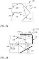
- FIG. 2Aillustrates a cross sectional view of a redirection coupler in an example, according to an embodiment consistent with the principles described herein.
- FIG. 2Billustrates a cross sectional view of a redirection coupler in an example, according to another embodiment consistent with the principles described herein.
- FIG. 3Aillustrates a cross sectional view of a portion of a dual light guide, grating-based backlight 100 including a multibeam diffraction grating in an example, according to an embodiment consistent with the principles described herein.
- FIG. 3Billustrates a perspective view of the dual light guide, grating-based backlight portion of FIG. 3A including the multibeam diffraction grating in an example, according to an embodiment consistent with the principles described herein.
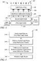
- FIG. 4illustrates a block diagram of a three-dimensional (3D) electronic display in an example, according to an embodiment consistent with the principles described herein.
- FIG. 5illustrates a flow chart of a method of grating-based backlight operation in an example, according to an embodiment consistent with the principles described herein.
- Embodiments in accordance with the principles described hereinprovide grating-based backlighting employing dual light guides.
- backlighting described hereinemploys a first light guide to propagate a beam of light in a first direction and a second light guide to propagate a redirected light beam in a second direction.
- a redirection coupleris configured to redirect the light beam of the first light guide to produce the redirected light beam in the second light guide.
- a plurality of diffraction gratingsis employed to diffractively scatter or couple light out of the second light guide and to direct the coupled-out light in a direction away from the diffraction grating (e.g., in a viewing direction of an electronic display).
- a light beam propagating in the first light guidemay spread into adjacent light beams in a predetermined manner.
- the spreadingmay reduce or substantially eliminate ‘striping’ that may occur (e.g., due to a lack of uniformity in a collimation of the light beams) without the spreading, for example.
- Reduced stripingmay provide more uniform or consistent illumination of the diffraction gratings and, in turn, improved evenness in the coupled-out light produced by diffractive scattering, according to various embodiments.
- the coupled-out light produced by the diffraction gratingsforms a plurality of light beams that is directed in a predefined direction such as an electronic display viewing direction.
- Light beams of the pluralitymay have different principal angular directions from one another, according to various embodiments of the principles described herein.
- the plurality of light beamsmay form or provide a light field in the viewing direction.
- the light beamsmay represent a plurality of primary colors, in some embodiments.
- the light beams having the different principal angular directionsalso referred to as ‘the differently directed light beams’
- representing different colorsmay be employed to display information including three-dimensional (3D) information.
- the differently directed, different color light beamsmay be modulated and serve as color pixels of a ‘glasses free’ 3D color electronic display.
- a ‘light guide’is defined as a structure that guides light within the structure using total internal reflection.
- the light guidemay include a core that is substantially transparent at an operational wavelength of the light guide.
- the term ‘light guide’generally refers to a dielectric optical waveguide that employs total internal reflection to guide light at an interface between a dielectric material of the light guide and a material or medium that surrounds that light guide.
- a condition for total internal reflectionis that a refractive index of the light guide is greater than a refractive index of a surrounding medium adjacent to a surface of the light guide material.
- the light guidemay include a coating in addition to or instead of the aforementioned refractive index difference to further facilitate the total internal reflection.
- the coatingmay be a reflective coating, for example.
- the light guidemay be any of several light guides including, but not limited to, one or both of a plate or slab guide and a strip guide.
- a platewhen applied to a light guide as in a ‘plate light guide’ is defined as a piece-wise or differentially planar layer or sheet, which is sometimes referred to as a ‘slab’ guide.
- a plate light guideis defined as a light guide configured to guide light in two substantially orthogonal directions bounded by a top surface and a bottom surface (i.e., opposite surfaces) of the light guide.
- the top and bottom surfacesare both separated from one another and may be substantially parallel to one another in at least a differential sense, according to some embodiments. That is, within any differentially small section of the plate light guide, the top and bottom surfaces are substantially parallel or co-planar.
- the plate light guidemay be have a wedge shape in which a space between the top and bottom surfaces changes as a function of distance across the plate light guide.
- the wedge shapemay comprise a top surface to bottom surface spacing that increases with distance from an input end (e.g., adjacent to a light source) to an output or terminal end of the wedge-shaped plate light guide.
- Such a wedge-shaped light guidemay provide collimation (e.g., vertical collimation) of light introduced at the input end, for example.
- a plate light guidemay be substantially flat (i.e., confined to a plane) and so the plate light guide is a planar light guide.
- the plate light guidemay be curved in one or two orthogonal dimensions.
- the plate light guidemay be curved in a single dimension to form a cylindrical shaped plate light guide.
- any curvaturehas a radius of curvature sufficiently large to insure that total internal reflection is maintained within the plate light guide to guide light.
- a diffraction grating(e.g., a multibeam diffraction grating) may be employed to scatter or couple light out of a light guide (e.g., a plate light guide) as a light beam.
- a ‘diffraction grating’is generally defined as a plurality of features (i.e., diffractive features) arranged to provide diffraction of light incident on the diffraction grating.
- the plurality of featuresmay be arranged in a periodic or quasi-periodic manner.
- the diffraction gratingmay include a plurality of features (e.g., a plurality of grooves in a material surface) arranged in a one-dimensional (1-D) array.
- the diffraction gratingmay be a two-dimensional (2-D) array of features.
- the diffraction gratingmay be a 2-D array of bumps on or holes in a material surface, for example.
- the ‘diffraction grating’is a structure that provides diffraction of light incident on the diffraction grating. If the light is incident on the diffraction grating from a light guide, the provided diffraction or diffractive scattering may result in, and thus be referred to as, ‘diffractive coupling’ in that the diffraction grating may couple light out of the light guide by diffraction. The diffraction grating also redirects or changes an angle of the light by diffraction (i.e., at a diffractive angle).
- the diffraction gratingmay be understood to be a structure including diffractive features that diffractively redirects light incident on the diffraction grating and, if the light is incident from a light guide, the diffraction grating may also diffractively couple out the light from the light guide.
- the features of a diffraction gratingare referred to as ‘diffractive features’ and may be one or more of at, in and on a surface (i.e., wherein a ‘surface’ refers to a boundary between two materials).
- the surfacemay be a surface of a plate light guide.
- the diffractive featuresmay include any of a variety of structures that diffract light including, but not limited to, one or more of grooves, ridges, holes and bumps, and these structures may be one or more of at, in and on the surface.
- the diffraction gratingmay include a plurality of parallel grooves in a material surface.
- the diffraction gratingmay include a plurality of parallel ridges rising out of the material surface.
- the diffractive featuresmay have any of a variety of cross sectional shapes or profiles that provide diffraction including, but not limited to, one or more of a sinusoidal profile, a rectangular profile (e.g., a binary diffraction grating), a triangular profile and a saw tooth profile (e.g., a blazed grating).
- a ‘multibeam diffraction grating’is a diffraction grating that produces coupled-out light that includes a plurality of light beams. Further, the light beams of the plurality produced by a multibeam diffraction grating have different principal angular directions from one another, by definition herein. In particular, by definition, a light beam of the plurality has a predetermined principal angular direction that is different from another light beam of the light beam plurality as a result of diffractive coupling and diffractive redirection of incident light by the multibeam diffraction grating.
- the light beam pluralitymay represent a light field. For example, the light beam plurality may include eight light beams that have eight different principal angular directions.
- the eight light beams in combinationmay represent the light field, for example.
- the different principal angular directions of the various light beamsare determined by a combination of a grating pitch or spacing and an orientation or rotation of the diffractive features of the multibeam diffraction grating at points of origin of the respective light beams relative to a propagation direction of the light incident on the multibeam diffraction grating.
- the light coupled out of the light guide by the diffraction gratingrepresents a pixel of an electronic display.
- the light guide having a multibeam diffraction grating to produce the light beams of the plurality having different principal angular directionsmay be part of a backlight of or used in conjunction with an electronic display such as, but not limited to, a ‘glasses free’ three-dimensional (3D) electronic display (also referred to as a multiview or ‘holographic’ electronic display or an autostereoscopic display).
- 3Dthree-dimensional
- the differently directed light beams produced by coupling out guided light from the light guide using the multibeam diffractive gratingmay be or represent ‘pixels’ of the 3D electronic display.
- the differently directed light beamsmay form a light field.
- a ‘collimating’ mirroris defined as a mirror having a curved shape that is configured to collimate light reflected by the collimating mirror.
- the collimating mirrormay have a reflecting surface characterized by a parabolic curve or shape.
- the collimating mirrormay comprise a shaped parabolic mirror.
- shaped parabolicit is meant that a curved reflecting surface of the shaped parabolic mirror deviates from a ‘true’ parabolic curve in a manner determined to achieve a predetermined reflection characteristics (e.g., degree of collimation).
- the collimating mirrormay be a continuous mirror (i.e., having a substantially smooth, continuous reflecting surface), while in other embodiments the mirror may comprise a Fresnel reflector or Fresnel mirror that provides light collimation.
- an amount of collimation provided by the collimating mirrormay vary in a predetermined degree or amount of collimation from one embodiment to another.
- the collimating mirrormay be configured to provide collimation in one or both of two orthogonal directions (e.g., a vertical direction and a horizontal direction). That is, the collimating mirror may include a parabolic or shaped parabolic shape in one or both of two orthogonal directions, according to various examples.
- the article ‘a’is intended to have its ordinary meaning in the patent arts, namely ‘one or more’.
- ‘a grating’means one or more gratings and as such, ‘the grating’ means ‘the grating(s)’ herein.
- any reference herein to ‘top’, ‘bottom’, ‘upper’, ‘lower’, ‘up’, ‘down’, ‘front’, back′, ‘first’, ‘second’, ‘left’ or ‘right’is not intended to be a limitation herein.
- the term ‘about’ when applied to a valuegenerally means within the tolerance range of the equipment used to produce the value, or may mean plus or minus 10%, or plus or minus 5%, or plus or minus 1%, unless otherwise expressly specified.
- the term ‘substantially’ as used hereinmeans a majority, or almost all, or all, or an amount within a range of about 51% to about 100%.
- examples hereinare intended to be illustrative only and are presented for discussion purposes and not by way of limitation.
- FIG. 1Aillustrates a cross sectional view of a dual light guide, grating-based backlight 100 in an example, according to an embodiment consistent with the principles described herein.
- FIG. 1Billustrates a cross sectional view of a dual light guide, grating-based backlight 100 in an example, according to another embodiment consistent with the principles described herein.
- the dual light guide, grating-based backlight 100is configured to produce a plurality of light beams 102 .
- the plurality of light beams 102may correspond to information contained in pixels of an electronic display that employs the dual light guide, grating-based backlight 100 , according to various examples and embodiments.
- the plurality of light beams 102may form a light field in a viewing direction of an electronic display that employs the dual light guide, grating-based backlight 100 .
- a light beam 102 of the plurality of light beams 102 (and within the light field) provided by the dual light guide, grating-based backlight 100may be configured to have a different principal angular direction from other light beams 102 of the plurality.
- the light beam 102may have both a predetermined direction (principal angular direction) and a relatively narrow angular spread within the light field.
- the principal angular direction of the light beam 102may correspond to an angular direction of a particular view of the 3D electronic display.
- the light beam 102may represent or correspond to a pixel of the 3D electronic display, according to some examples.
- light beams 102 of the pluralitymay have substantially similar predetermined principal angular directions (not illustrated in FIGS. 1A-1B ).
- the similarly directed light beams 102generally do not form a light field, but instead represent light emitted by the dual light guide, grating-based backlight 100 that is substantially unidirectional (e.g., perpendicular to a surface of the dual light guide, grating-based backlight 100 ).
- the similarly directed light beams 102may be used as a backlight for a two-dimensional (2D) electronic display, for example.
- the light beams 102 of the plurality produced by the dual light guide, grating-based backlight 100may be modulated (e.g., by a light valve as described below).
- the modulation of the light beams 102 directed in different angular directions away from the dual light guide, grating-based backlight 100may be particularly useful for dynamic 3D color electronic display applications, for example. That is, the individually modulated light beams 102 of different colors and directed in a particular view direction may represent dynamic color pixels of the 3D electronic display corresponding to the particular view direction.
- dynamic 2D electronic display applicationsmay be supported when the light beams 102 are substantially unidirectional.
- the dual light guide, grating-based backlight 100comprises a first plate light guide 110 .
- the first plate light guide 110is configured to guide light (e.g., from a light source described below) as a guided light beam 104 .
- the guided light beam 104is guided in a first direction (e.g., to the right as illustrated in FIGS. 1A and 1B ).
- the first plate light guide 110is configured to guide the guided light beam 104 at a non-zero propagation angle, according to various embodiments.
- the first plate light guide 110may include a dielectric material configured as an optical waveguide.
- the dielectric materialmay have a first refractive index that is greater than a second refractive index of a medium surrounding the dielectric optical waveguide.
- the difference in refractive indicesis configured to facilitate total internal reflection of the guided light beam 104 according to one or more guided modes of the light guide 110 , for example.
- the non-zero propagation angleis an angle relative to a surface (e.g., a top surface or a bottom surface) of the plate light guide 110 .
- the non-zero propagation angle of the guided light beam 104may be between about ten (10) degrees and about fifty (50) degrees or, in some examples, between about twenty (20) degrees and about forty (40) degrees, or between about twenty-five (25) degrees and about thirty-five (35) degrees.
- the non-zero propagation anglemay be about thirty (30) degrees.
- the non-zero propagation anglemay be about 20 degrees, or about 25 degrees, or about 35 degrees.
- the light to be guided as the guided light beam 104is introduced or coupled into the first plate light guide 110 at the non-zero propagation angle (e.g., about 30-35 degrees).
- the non-zero propagation anglee.g., about 30-35 degrees.
- a lensnot illustrated
- a mirror or similar reflectore.g., a tilted collimating reflector
- a prismnot illustrated
- the guided light beam 104propagates along the first plate light guide 110 in the first direction that is generally away from the input end (e.g., illustrated by bold arrows pointing along an x-axis in FIGS.
- the guided light beam 104propagates by reflecting or ‘bouncing’ between the top surface and the bottom surface of the plate light guide 110 at the non-zero propagation angle (e.g., illustrated by an extended, angled arrow representing a light ray of the guided light beam 104 ).
- the guided light beam 104 produced by coupling light into the plate light guide 110may be collimated (e.g., may be a collimated light beam), according to some examples. Further, according to some examples, the guided light beam 104 may be collimated in a plane that is perpendicular to a plane of a surface of the first plate light guide 110 .
- the first plate light guide 110may be oriented in a horizontal plane having a top and bottom surface parallel to an x-y plane (e.g., as illustrated).
- the guided light beam 104may be collimated or substantially collimated in a vertical plane (e.g., an x-z plane), for example.
- the first plate light guide 110may be a wedge-shaped plate light guide 110 .
- One of the top or bottom surfacemay be parallel to the x-y plane when the first plate light guide 110 is wedge-shaped, for example.
- the guided light beam 104may also be collimated or substantially collimated in a horizontal direction (e.g., in the x-y plane).
- a ‘collimated’ light beamis defined as a beam of light in which rays of the light beam are substantially parallel to one another within the light beam (e.g., the guided light beam 104 ). Further, rays of light that diverge or are scattered from the collimated light beam are not considered to be part of the collimated light beam, by definition herein. Collimation of the light to produce the collimated guided light beam 104 may be provided by the lens or mirror (e.g., tilted collimating reflector, etc.) used to couple the light into the first plate light guide 110 , according to various embodiments.
- the lens or mirrore.g., tilted collimating reflector, etc.
- the first plate light guide 110is a slab or plate optical waveguide comprising an extended, substantially planar sheet of optically transparent, dielectric material.
- the substantially planar sheet of dielectric materialis configured to guide the guided light beam 104 using total internal reflection.
- the optically transparent material of the first plate light guide 110may comprise any of a variety of dielectric materials including, but not limited to, one or more of various types of glass (e.g., silica glass, alkali-aluminosilicate glass, borosilicate glass, etc.) and substantially optically transparent plastics or polymers (e.g., poly(methyl methacrylate) or ‘acrylic glass’, polycarbonate, etc.).
- the first plate light guide 110may further include a cladding layer on at least a portion of a surface (e.g., one or both of the top surface and the bottom surface) of the first plate light guide 110 (not illustrated).
- the cladding layermay be used to further facilitate total internal reflection, according to some examples.
- the dual light guide, grating-based backlight 100 illustrated in FIGS. 1A-1Bfurther comprises a second plate light guide 120 .
- the second light guide 120is configured to receive and guide a redirected light beam 106 in a second direction (e.g., to the left as illustrated).
- the second directionmay be substantially opposite to the first direction.
- the first plate light guide 110 and the second plate light guide 120may be substantially parallel or co-planar to one another (e.g., stacked one on top of the other, as illustrated).
- the first directionmay be in a positive x-direction
- the second directionmay be in a negative x-direction, as illustrated in FIGS. 1A-1B , by way of example and not limitation.
- the second directionmay be substantially perpendicular or at another angle relative to the first direction.
- the first directionmay be in the x-direction and the second direction may be in a y-direction (not illustrated).
- the first directionmay be a z-direction and the second direction may be in an x-y plane.
- the second directionmay be substantially any direction other than the first direction, according to various embodiments.
- the second plate light guide 120may be substantially similar to the first plate light guide 110 .
- the second plate light guide 120may be a slab or plate optical waveguide comprising an extended, substantially planar sheet of optically transparent, dielectric material configured to guide the redirected light beam 106 using total internal reflection, as is described above with respect to the first plate light guide 110 .
- the second plate light guide 120may further include a cladding layer on at least a portion of a surface (e.g., one or both of the top surface and the bottom surface) of the second plate light guide 120 (not illustrated) to further facilitate total internal reflection, also as described above.
- the dual light guide, grating-based backlight 100further comprises a redirection coupler 130 , according to various embodiments.
- the redirection coupler 130is configured to redirect the guided light beam 104 of the first plate light guide 110 in a second direction as the redirected light beam 106 .
- the redirected light beam 106is then received and guided by the second plate light guide 120 , according to various embodiments.
- the redirection coupler 130substantially ‘turns’ the guided light beam 104 in a new or different direction the redirected light beam 106 .
- the second direction of the redirected light beam 106is different from the first direction and may be substantially opposite to the first direction of the guided light beam 104 , as illustrated in FIG. 1A-1B by way of example.
- the redirection coupler 130may preserve or substantially preserve collimation of the guided light beam 104 within the redirected light beam 106 .
- FIG. 2Aillustrates a cross sectional view of a redirection coupler 130 in an example, according to an embodiment consistent with the principles described herein.
- the redirection coupler 130 illustrated in FIG. 2Ais a corner reflector located at an output end of the first plate light guide 110 and at an input end of the second plate light guide 120 .
- the corner reflector of the redirection coupler 130may include a pair of mirrors 132 or equivalent reflectors (e.g., total internal reflection or ‘TIR’ mirror, a Bragg mirror, etc.) arranged at an angle to one another.
- TIRtotal internal reflection
- Bragg mirrora Bragg mirror
- a first mirror 132 ′ of the corner reflector mirror pair 132is positioned to reflect the guided light beam 104 from the first plate light guide 110 to a second mirror 132 ′′ of the corner reflector mirror pair 132 .
- the second mirror 132 ′′is positioned to further reflect the reflected light beam into the second plate light guide 120 .
- the position of the second mirror 132 ′′ relative to the first mirror 132 ′is configured to reflect light at an angle different from the angle of reflection by the first mirror 132 ′.
- reflection at the second mirror 132 ′′then provides the redirected light beam 106 (i.e., redirects the reflected light beam), which enters and is guided by the second plate light guide 120 in the second direction.
- the combined reflections at the first and second mirrors 132 ′, 132 ′′are configured to provide the redirected light beam 106 with a predetermined, non-zero propagation angle within the second plate light guide 120 .
- a relationship between the non-zero propagation angle of the guided light beam 104 in the first plate light guide 110 and the predetermined, non-zero propagation angle of the redirected light beam 106 guided within the second plate light guide 120is determined by both a relative orientation of the first and second mirrors 132 ′, 132 ′′ to one another and an orientation of the corner reflector relative to the first and second plate light guides 110 , 120 , according to various embodiments.
- the pair of mirrors 132 of the corner reflectormay be oriented at a ninety (90) degree angle to one another.
- the corner reflectoris a retroreflector (i.e., a 90-degree corner reflector).
- the corner reflector of the redirection coupler 130may be tilted relative to a plane of one or both of the first plate light guide 110 and the second plate light guide 120 .
- the tilt of the corner reflector (or of the redirection coupler 130 )is configured to provide the predetermined, non-zero propagation angle of the redirected light beam 106 .
- a tilt of zero degreesproduces a redirected light beam 106 having a predetermined, non-zero propagation angle that is equal to the non-zero propagation angle of the guided light beam 104 , e.g., as illustrated in FIG. 2A .
- the predetermined, non-zero propagation angle of the redirected light beam 106may still be provided by an appropriate adjustment of an angular relationship between the corner reflector mirror pair 132 and the first and second plate light guides 110 , 120 , for example.
- the predetermined, non-zero propagation angle of the redirected light beam 106may be readily determined for the various angular relationships between the mirrors 132 ′, 132 ′′ themselves and between the pair of mirrors 132 and the plate light guides 110 , 120 for a given the non-zero propagation angle of the guided light beam 104 using geometric optics.
- FIG. 2Billustrates a cross sectional view of a redirection coupler 130 in an example, according to another embodiment consistent with the principles described herein.
- the redirection coupler 130comprises a tilted mirror 134 and a grating coupler 136 .
- tiltedit is meant that the mirror 134 has a tilt angle relative to a plane of or surface of the first plate light guide 110 , according to various embodiments.
- the tilted mirror 134is configured to reflect the guided light beam 104 from the first plate light guide 110 toward the grating coupler 136 as a reflected light beam 104 ′.
- the tilt angle of the tilted mirror 134not only directs the reflected light beam 104 ′ at the grating coupler 136 , but also determines an angle of incidence of the reflected light beam 104 ′ at the grating coupler 136 .
- the grating coupler 136comprises a diffraction grating configured to diffract the reflected light beam 104 ′ received from the tilted mirror 134 .
- the grating coupler 136diffracts the reflected light beam 104 ′ into the second direction as the redirected light beam 106 to be guided in the second plate light guide 120 , according to various embodiments.
- a combination of the reflection by the tilted mirror 134 and the diffraction of the grating coupler 136may provide the predetermined, non-zero propagation angle of the redirected light beam 106 within the second plate light guide 120 .
- a tilt angle ⁇ of the tilted mirror 134configured to provide normal incidence of the reflected light beam 104 ′ at the grating coupler 136 may be determined according equation (1) as
- ⁇45 ⁇ ° - ⁇ 2 ( 1 )
- ⁇is the non-zero propagation angle of the guided light beam 104 , both of the non-zero propagation angle ⁇ and the tilt angle ⁇ being angles from a plane of the first plate light guide 110 .
- the redirection coupler 130further comprises a second mirror 138 .
- the second mirror 138is configured to reflect and redirect light of a secondary diffraction product of the grating coupler 136 .
- the second mirror 138is oriented to reflect and redirect the secondary diffraction product light into the second direction to augment the redirected light beam 106 within the second plate light guide 120 .
- the redirected light beam 106may correspond to light of a primary diffraction product (e.g., a positive, first order diffraction product).
- a solid lineis used to denote light of the primary diffraction product (i.e., light beam 106 ) and a dashed line between the grating coupler 136 and the second mirror 138 denotes light of the secondary diffraction product.
- the second mirror 138may be oriented to reflect and redirect the secondary diffraction product (e.g., a negative, first order diffraction product) in the second direction and at a non-zero propagation angle that is about equal to the predetermined, non-zero propagation angle of the redirected light beam 106 within the second plate light guide 120 .
- a beam of light 106 ′(dashed-line 106 ′ in FIG. 2B ) corresponding to the reflected and redirected secondary diffraction product will effectively add to or augment the redirected light beam 106 resulting in an improved efficiency of the redirection coupler 130 compared to embodiments without the second mirror 138 , according to some embodiments.
- the tilted mirror 134is configured reflect the guided light beam 104 of the first plate light guide 110 toward the grating coupler 136 to provide a substantially normal angle of incidence of the reflected light beam 104 ′ at the grating coupler 136 .
- the primary diffraction product of the diffraction grating of the grating coupler 136may be the positive first order diffraction product, a diffraction angle of which corresponds to the predetermined, non-zero propagation angle of the redirected light beam 106 .
- the second mirror 138may be oriented at a ninety (90) degree angle to the grating coupler 136 , as illustrated in FIG.
- the secondary diffraction productmay be a negative, first order diffraction product that has a 90-degree relationship to the primary diffraction product (i.e., the positive, first order diffraction product).
- the 90-degree oriented second mirror 138is configured to reflect and redirect the secondary diffraction product as the light beam 106 ′ in the second plate light guide 120 at substantially the same non-zero propagation angle as that of the redirected light beam 106 . As such, the redirected light beam 106 is substantially augmented with the light beam 106 ′ in the second plate light guide 120 .
- the tilted mirror 134may be virtually any mirror or equivalent reflector that reflects or substantially reflects the guided light beam 104 and further that is tilted at an angle configured to change a direction of the guided light beam 104 .
- the tilted mirror 134may comprise a metal or metalized surface (e.g., a silvered mirror).
- the tilted mirror 134may be a Bragg mirror.
- the tilted mirror 134be realized by total internal reflection (TIR) and be a TIR mirror.
- the tilted mirror 134may be provided by a beveled surface of the first plate light guide 110 and TIR within the first plate light guide 110 in the vicinity of the beveled surface may serve as the tilted mirror 134 .
- the second mirror 138may be substantially any mirror or equivalent reflector including, but not limited to, a metal or metalized surface, a Bragg mirror and a TIR mirror.
- the second mirror 138may be provided by metalizing an end of the second plate light guide 120 .
- the end of the second plate light guide 120is configured to provide TIR of the secondary diffraction product incident on the second plate light guide end as the second mirror 138 .
- one or more of the mirrors described abovemay be a collimating mirror.
- one or both of the corner reflector mirrors 132 ′, 132 ′′may have a parabolic curved surface that provides collimation of the redirected light beam 106 (e.g., in a horizontal direction, a vertical direction or both).
- one or both of the tilted mirror 134 and the second mirror 138may be a collimating mirror having a parabolic curved surface to collimate the reflected light beam 104 ′ resulting in collimation (e.g., one or both of vertical and horizontal collimation) of the redirected light beam 106 (e.g., after diffraction by the grating coupler 136 ).
- the grating coupler 136comprises diffractive features (e.g., grooves or ridges) spaced apart from one another to form a diffraction grating.
- the diffractive featuresmay be either at, in or adjacent to a surface of the second plate light guide 120 .
- the grating coupler 136may comprise a plurality of grooves formed in a top surface of the second plate light guide 120 within the redirection coupler 130 .
- the diffraction gratingcomprises uniform or substantially uniform spacing between the diffractive features. Further, a zero order diffraction product of the diffraction grating may be suppressed, according to various embodiments.
- the diffraction gratingmay have a diffractive feature height or depth (e.g., ridge height or groove depth) and a duty cycle selectively chosen to suppress the zero order diffraction product.
- the duty cyclemay be between about thirty percent (30%) and about seventy percent (70%).
- the height or depthmay range from greater than zero to about five hundred nanometers.
- the duty cyclemay be about fifty (50) percent and the diffractive feature height or depth may be about one hundred forty (140) nanometers.
- the grating coupler 136comprises a reflective diffraction grating such as, but not limited to, a reflective metal or metalized diffraction grating.
- FIG. 2Billustrates the grating coupler 136 comprising diffractive features 136 a as ridges on (or protruding from) the top surface of the second plate light guide 120 . Further, spaces between and above the diffractive features 136 a are filled by a layer 136 b of a reflective material, such as a reflective metal.
- the reflective metalmay include, but is not limited to, aluminum, nickel, silver or gold.
- Using a reflective diffraction gratingmay provide a higher diffraction efficiency compared to a dielectric diffraction grating (i.e., grooves or ridges in a dielectric material of the second plate light guide 120 , for example).
- the dual light guide, grating-based backlight 100further comprises a diffraction grating 140 .
- the dual light guide, grating-based backlight 100may comprise a plurality of diffraction gratings 140 , according to some embodiments.
- the plurality of diffraction gratings 140may be arranged as or represent an array of diffraction gratings 140 , for example.
- the diffraction gratings 140are located at a surface of the second plate light guide 120 (e.g., a top or front surface).
- one or more of the diffraction gratings 140may be located within the second plate light guide 120 . In yet other embodiments (not illustrated), one or more of the diffraction gratings 140 may be located at or on a bottom or back surface of the second plate light guide 120 .
- the diffraction grating 140is configured to scatter or couple out a portion of the redirected light beam 106 from the second plate light guide 120 by or using diffractive coupling (e.g., also referred to as ‘diffractive scattering’), according to various embodiments.
- the portion of the redirected light beam 106may be diffractively coupled out by the diffraction grating 140 through the light guide surface (e.g., through the top or front surface of the second plate light guide 120 ).
- the diffraction grating 140is configured to diffractively couple out the portion of the redirected light beam 106 as a coupled-out light beam (e.g., a light beam 102 ).
- the coupled-out light beam 102is directed away from the light guide surface at a predetermined principal angular direction, according to various examples.
- the coupled-out portion of the redirected light beam 106is diffractively redirected away from the light guide surface by the plurality of diffraction gratings 140 as the plurality of light beams 102 .
- each of the light beams 102 of the light beam pluralitymay have a different principal angular direction and the light beam plurality may represent a light field, according to some examples.
- each of the light beams 102 of the light beam pluralitymay have substantially the same principal angular direction and the light beam plurality may represent substantially unidirectional light as opposed to the light field represented by the light beam plurality having light beams with different principal angular directions.
- the diffraction grating 140comprises a plurality of diffractive features 142 that diffract light (i.e., provide diffraction).
- the diffractionis responsible for the diffractive coupling of the portion of the redirected light beam 106 out of the second plate light guide 120 .
- the diffraction grating 140may include one or both of grooves in a surface of the second plate light guide 120 and ridges protruding from the second light guide surface that serve as the diffractive features 142 .
- the grooves and ridgesmay be arranged parallel or substantially parallel to one another and, at least at some point, perpendicular to a propagation direction of the redirected light beam 106 that is to be coupled out by the diffraction grating 140 .
- the diffractive featuresmay be etched, milled or molded into the surface or applied on the surface.
- a material of the diffraction grating 140may include a material of the second plate light guide 120 .
- the diffraction gratings 140comprise substantially parallel grooves formed in the surface of the second plate light guide 120 .
- the diffraction gratings 140comprise substantially parallel ridges that protrude from the second light guide surface, for example.
- the diffraction gratings 140may be implemented in or as a film or layer applied or affixed to the surface of the second light guide 120 .
- the plurality of diffraction gratings 140may be arranged in a variety of configurations with respect to the second plate light guide 120 .
- the plurality of diffraction gratings 140may be arranged in columns and rows across the light guide surface (e.g., as an array).
- a plurality of diffraction gratings 140may be arranged in groups and the groups may be arranged in rows and columns.
- the plurality of diffraction gratings 140may be distributed substantially randomly across the surface of the second plate light guide 120 .
- the plurality of diffraction gratings 140comprises a multibeam diffraction grating 140 .
- all or substantially all of the diffraction gratings 140 of the pluralitymay be multibeam diffraction gratings 140 (i.e., a plurality of multibeam diffraction gratings 140 ).
- the multibeam diffraction grating 140is a diffraction grating 140 that is configured to couple out the portion of the redirected light beam 106 as a plurality of light beams 102 (e.g., as illustrated in FIGS. 1A and 1B ), having different principal angular directions that forms a light field, according to various embodiments.
- the multibeam diffraction grating 140may comprise a chirped diffraction grating 140 (i.e., a chirped multibeam diffraction grating).
- the ‘chirped’ diffraction grating 140is a diffraction grating exhibiting or having a diffraction spacing of the diffractive features that varies across an extent or length of the chirped diffraction grating 140 .
- the varying diffraction spacingis defined as a ‘chirp’.
- the redirected light beam 106 that is diffractively coupled out of the second plate light guide 120exits or is emitted from the chirped diffraction grating 140 as the light beams 102 at different diffraction angles corresponding to different points of origin across the chirped diffraction grating 140 .
- the chirped diffraction grating 140is responsible for respective predetermined and different principal angular directions of the coupled-out light beams 102 of the light beam plurality.
- FIG. 3Aillustrates a cross sectional view of a portion of a dual light guide, grating-based backlight 100 including a multibeam diffraction grating 140 in an example, according to an embodiment consistent with the principles described herein.
- FIG. 3Billustrates a perspective view of the dual light guide, grating-based backlight portion of FIG. 3A including the multibeam diffraction grating 140 in an example, according to an embodiment consistent with the principles described herein.
- the multibeam diffraction grating 140 illustrated in FIG. 3Acomprises grooves in a surface of the second plate light guide 120 , by way of example and not limitation.
- the multibeam diffraction grating 140 illustrated in FIG. 3Amay represent one of the groove-based diffraction gratings 140 illustrated in FIG. 1A .
- the multibeam diffraction grating 140is a chirped diffraction grating.
- the diffractive features 142are closer together at a first end 140 ′ of the multibeam diffraction grating 140 than at a second end 140 ′′.
- the diffractive spacing d of the illustrated diffractive features 142varies linearly from the first end 140 ′ to the second end 140 ′′.
- the chirped diffraction grating 140may have or exhibit a chirp of the diffractive spacing d that varies linearly with distance.
- the chirped diffraction grating 140may be referred to as a ‘linearly chirped’ diffraction grating.
- the light beams 102 produced by coupling light out of the second plate light guide 120 using the multibeam diffraction grating 140may diverge (i.e., be diverging light beams 102 ) when the redirected light beam 106 propagates in the second plate light guide 120 in a direction from the first end 140 ′ of the multibeam diffraction grating 140 to the second end 140 ′′ of the multibeam diffraction grating 140 (e.g., as illustrated in FIG. 3A ).
- converging light beams 102may be produced when the redirected light beam 106 propagates in the reverse direction in the second plate light guide 120 , i.e., from the second end 140 ′′ to the first end 140 ′ of the multibeam diffraction grating 140 , according to other examples (not illustrated).
- the chirped diffraction grating 140may exhibit a non-linear chirp of the diffractive spacing d.
- Various non-linear chirps that may be used to realize the chirped diffraction grating 140include, but are not limited to, an exponential chirp, a logarithmic chirp or a chirp that varies in another, substantially non-uniform or random but still monotonic manner.
- Non-monotonic chirpssuch as, but not limited to, a sinusoidal chirp or a triangle or sawtooth chirp, may also be employed. Combinations of any of these types of chirps may also be used.
- the multibeam diffraction grating 140includes diffractive features 142 (e.g., grooves or ridges) in, at or on a surface of the second plate light guide 120 that are both chirped and curved (i.e., the multibeam diffraction grating 140 is a curved, chirped diffraction grating).
- the redirected light beam 106has an incident direction relative to the multibeam diffraction grating 140 and the second plate light guide 120 , as illustrated by a bold arrow labeled ‘ 106 ’ in FIGS. 3A-3B .
- the plurality of coupled-out or emitted light beams 102pointing away from the multibeam diffraction grating 140 at the surface of the second plate light guide 120 .
- the illustrated light beams 102are emitted in a plurality of predetermined different principal angular directions.
- the predetermined different principal angular directions of the emitted light beams 102are different in both azimuth and elevation (e.g., to form a light field), as illustrated.
- both the predefined chirp of the diffractive features 142 and the curve of the diffractive features 142may be responsible for a respective plurality of predetermined different principal angular directions of the emitted light beams 102 .
- the diffractive features 142 within the multibeam diffraction grating 140may have varying orientations relative to an incident direction of the redirected light beam 106 guided in the second plate light guide 120 .
- an orientation of the diffractive features 142 at a first point or location within the multibeam diffraction grating 140may differ from an orientation of the diffractive features 142 at another point or location relative to the guided light beam incident direction.
- an azimuthal component ⁇ of the principal angular direction ⁇ , ⁇ of the light beam 102may be determined by or correspond to the azimuthal orientation angle ⁇ f of the diffractive features 142 at a point of origin of the light beam 102 (i.e., at a point where the incident redirected light beam 106 is coupled out), according to some examples.
- the varying orientations of the diffractive features 142 within the multibeam diffraction grating 140produce different light beams 102 having different principle angular directions ⁇ , ⁇ , at least in terms of their respective azimuthal components ⁇ .
- an ‘underlying diffraction grating’ of the multibeam diffraction grating 140 associated with the curved diffractive features 142has different azimuthal orientation angles ⁇ f .
- underlying diffraction gratingit is meant that a diffraction grating of a plurality of non-curved diffraction gratings that in superposition yield the curved diffractive features of the multibeam diffraction grating 140 .
- the curvehas a particular azimuthal orientation angle ⁇ f that generally differs from the azimuthal orientation angle ⁇ f at another point along the curved diffractive features 142 .
- the particular azimuthal orientation angle ⁇ fresults in a corresponding azimuthal component of a principal angular direction ⁇ , ⁇ of a light beam 102 emitted from the given point.
- the curve of the diffractive features 142e.g., grooves, ridges, etc.
- the circlemay be coplanar with the light guide surface.
- the curvemay represent a section of an ellipse or another curved shape, e.g., that is coplanar with the light guide surface.
- the multibeam diffraction grating 140may include diffractive features 142 that are ‘piecewise’ curved.
- the diffractive feature 142may not describe a substantially smooth or continuous curve per se, at different points along the diffractive feature 142 within the multibeam diffraction grating 140 , the diffractive feature 142 still may be oriented at different angles with respect to the incident direction of the redirected light beam 106 .
- the diffractive feature 142may be a groove including a plurality of substantially straight segments, each segment having a different orientation than an adjacent segment. Together, the different angles of the segments may approximate a curve (e.g., a segment of a circle), according to various embodiments.
- the diffractive features 142may merely have different orientations relative to the incident direction of the guided light at different locations within the multibeam diffraction grating 140 without approximating a particular curve (e.g., a circle or an ellipse).
- the dual light guide, grating-based backlight 100further comprises a light source 150 , according to some embodiments.
- the light source 150may be coupled to an input end of the first plate light guide 110 opposite to the output end adjacent to the redirection coupler 130 , for example.
- the light source 150includes a plurality of optical emitters 152 .
- the optical emitters 152are (or more generally the light source 150 is) configured to provide light to the first plate light guide 110 as the guided light 104 , i.e., as the guided light beam 104 .
- the provided lightcomprises a plurality of different colors of light that, when coupled into the plate light guide 110 , is configured to be guided as a plurality of different color light beams 104 , according to various embodiments.
- the plurality of optical emitters 152is configured to produce the plurality of different colors of light.
- the guided light beams 104 of different colorsare configured to be guided within the first plate light guide 110 at different, color-specific, non-zero propagation angles.
- a red guided light beam 104may be coupled into and propagates within the first plate light guide 110 at a first non-zero propagation angle
- a green guided light beam 104may be coupled into and propagates within the first plate light guide 110 at a second non-zero propagation angle
- a blue guided light beam 104may be coupled into and propagates within the first plate light guide 110 at a third non-zero propagation angle.
- the respective first, second and third non-zero propagation anglesare different from one another.
- the light source 150may further comprise a tilted, shaped parabolic reflector 154 .
- the different, color specific, non-zero propagation anglesmay be provided by respective red, green and blue optical emitters 152 of the optical emitter plurality laterally offset from one another (not separately illustrated in FIG. 1A ) that feed or emit into the tilted, shaped parabolic reflector 154 at the input end of the first plate light guide 110 , for example.
- the lateral offset of the different color emitters 152 in conjunction with the titled, shaped parabolic reflector 154is configured to couple the different light colors (e.g., red light, green light, and blue light) into the first plate light guide 110 at corresponding different, color-specific, non-zero propagation angles, according to various embodiments.
- the different light colorse.g., red light, green light, and blue light
- the redirection coupler 130may preserve or substantially preserve the color-specific, non-zero propagation angles when redirecting the different color guided light beams 104 into the second plate light guide 120 as redirected light beams 106 corresponding to the different colors.
- color-specific angular differences between the different color guided light beams 104may be substantially preserved upon redirection.
- the redirection coupler 130 implemented as a retroreflectormay preserve the color-specific, non-zero propagation angles of the different color guided light beams 104 in the corresponding different color redirected light beams 106 .
- the redirection coupler 130may adjust, augment or otherwise change one or more of the color specific, propagation angles and still maintain a difference therebetween upon redirection into the second plate light guide 120 , according to other embodiments.
- the guided light beams 104 of different colorsare configured to propagate within the first plate light guide 110 at similar or even about the same non-zero propagation angle.
- the redirection coupler 130may be configured to provide different, color-specific, non-zero propagation angles to the redirected light beams 106 of different colors.
- the light source 150may be configured to produce and introduce each of a red light, a green light and a blue light into first plate light guide 110 at substantially the same non-zero propagation angle (e.g., as opposed to different, color-specific, non-zero propagation angles).
- the redirection coupler 130may comprise a grating coupler configured to redirect the guided light beams of red, green and blue colors in the second direction in the second plate light guide 120 at respective different, color-specific, non-zero propagation angles.
- the grating couplermay be substantially similar to the grating coupler 136 described above, for example.
- the redirection coupler 130may further comprise a tilted mirror to reflect guided light beams of red, green and blue colors into the tilted mirror, as described above, for example.
- the light source 150may comprise substantially any source of light including, but not limited to, a light-emitting diode (LED) and a laser.
- the light source 150may produce a substantially monochromatic light having a narrowband spectrum denoted by a particular color.
- the colormay be or represent a primary color (e.g., of an electronic display).
- the light source 150may produce a plurality of different colors of light representing a plurality of different primary colors.
- the primary colorsmay comprise red light, green light and blue light, for example.
- the primary colorsmay be primary colors of a color electronic display, wherein the primary colors are selected according to a color model such as, but not limited to, a red-green-blue (RGB) color model configured to support a color gamut of the color electronic display.
- a color modelsuch as, but not limited to, a red-green-blue (RGB) color model configured to support a color gamut of the color electronic display.
- RGBred-green-blue
- the light source 150may be a multicolor light source comprising a plurality of LEDs. LEDs of the plurality may represent different colors of the primary colors of the color electronic display, for example.
- the LEDsmay comprise a red LED to produce red light, a green LED to produce green light, and a blue LED to produce blue light of the RGB color model, for example.
- the light source 150may comprise a linear array of optical emitters 152 arranged along the input end of the first plate light guide 110 . Each of the optical emitters may comprise a red LED, a green LED and blue LED, for example.
- the light source 150may be configured to produce collimated light (e.g., using a collimating reflector or lens).
- the tilted, shaped-parabolic reflector 154 illustrated in FIG. 1Amay be configured to produce a collimated light beam 104 when coupling light from the optical emitters 152 into the first plate light guide 110 .
- Substantially any collimatore.g., collimating lens, collimating reflector, etc.
- a three-dimensional (3D) electronic displayis provided.
- the 3D electronic displayis configured to emit modulated light beams having different directions as pixels of the 3D electronic display.
- the 3D electronic displayis configured to display 3D information (e.g., 3D images).
- the 3D electronic displayis an autostereoscopic or glasses-free 3D electronic display.
- different ones of the modulated, differently directed, light beamsmay correspond to different ‘views’ associated with the 3D electronic display, according to various examples.
- the different viewsmay provide a ‘glasses free’ (e.g., autostereoscopic, holographic, etc.) representation of information being displayed by the 3D electronic display, for example.
- FIG. 4illustrates a block diagram of a 3D electronic display 200 in an example, according to an embodiment consistent with the principles described herein.
- the 3D electronic display 200may be used to present 3D information such as, but not limited to, 3D images.
- the 3D electronic display 200 illustrated in FIG. 4is configured to emit modulated light beams 202 in different principal angular directions representing pixels corresponding to the different views of the 3D electronic display 200 .
- the modulated light beams 202are illustrated as diverging (e.g., as opposed to converging) in FIG. 4 , by way of example and not limitation.
- the light beams 202may further represent different colors and the 3D electronic display 200 may be a 3D color electronic display.
- the 3D electronic display 200 illustrated in FIG. 4comprises a first light guide 210 and a second light guide 220 configured to guide light.
- the guided light in the second light guide 220is a source of the light that becomes the modulated light beams 202 emitted by the 3D electronic display 200 .
- the first light guide 210may be a plate light guide and may be substantially similar to the first plate light guide 110 described above with respect to the dual light guide, grating-based backlight 100 .
- the second light guide 220may be a plate light guide and may be substantially similar to the second plate light guide 120 of dual light guide, grating-based backlight 100 , also described above.
- first and second light guides 210 , 220may each be a slab optical waveguide comprising a planar sheet of dielectric material configured to guide light by total internal reflection.
- first light guide 210 and the second light guide 220 as plate light guidesmay be arranged substantially co-planar to one another (e.g., as illustrated above in FIGS. 1A-1B ).
- first light guide 210 and the second light guide 220may comprise a strip light guide.
- first light guide 210 and the second light guide 220may comprise a plurality of substantially parallel strip light guides arranged adjacent to one another to approximate a plate light guide and thus be considered a form of a ‘plate’ light guide, by definition herein.
- the adjacent strip light guides of this form of plate light guidemay confine light within the respective strip light guides and substantially prevent leakage into adjacent strip light guides (i.e., unlike a substantially continuous slab of material of the ‘true’ plate light guide), for example.
- the guided light within each of the first and second light guides 210 , 220is configured to propagate at a non-zero propagation angle as a beam of light.
- the guided lightmay include a plurality of different color guided light beams.
- a guided light beam in one or both of the first light guide 210 and the second light guide 220may be collimated (i.e., the light may be guided as collimated or substantially collimated beams of light), according to some embodiments.
- the first and second light guides 210 , 220may be configured to guide light as a collimated light beam at a non-zero propagation angle within the respective light guides 210 , 220 .
- the 3D electronic display 200further comprises a redirection coupler 230 .
- the redirection coupler 230is configured to couple and redirect a guided light beam from the first light guide 210 into the second light guide 220 .
- the redirection coupler 230may be substantially similar to the redirection coupler 130 described above with respect to the dual light guide, grating-based backlight 100 .
- the redirection coupler 230may comprise a corner reflector (e.g., as illustrated in FIG. 2A ).
- the redirection coupler 230may comprise a tilted mirror and a reflective grating coupler (e.g., as illustrated in FIG. 2B ).
- the tilted mirror and reflective grating couplermay be substantially similar to the tilted mirror 134 and grating coupler 136 of the redirection coupler 130 , described above.
- the tilted mirrormay be configured to reflect the guided light beam from the first light guide 210 toward the reflective grating coupler.
- the reflective grating couplermay be configured to diffract and redirect the reflected guided light beam received from the tilted mirror into the second light guide 220 as a redirected light beam to be guided within the second light guide 220 .
- the 3D electronic display 200 illustrated in FIG. 4further comprises an array of multibeam diffraction gratings 240 .
- the array of multibeam diffraction gratings 240may be located in, on or at a surface of the second light guide 220 , for example.
- a multibeam diffraction grating 240 of the arrayis configured to diffractively couple out a portion of the redirected light beam guided within the second light guide 210 as plurality of coupled-out light beams 204 having different principal angular directions representing or corresponding to different views of the 3D electronic display 200 .
- the multibeam diffraction gratings 240may be substantially similar to the multibeam diffraction gratings 140 of the dual light guide, grating-based backlight 100 , described above.
- the array of multibeam diffraction gratings 240may include a chirped diffraction grating.
- diffractive features (e.g., grooves, ridges, etc.) of the multibeam diffraction gratings 240are curved diffractive features.
- the curved diffractive featuresmay include ridges or grooves that are curved (i.e., continuously curved or piece-wise curved) and spacings between the curved diffractive features that vary as a function of distance across the multibeam diffraction gratings 240 of the array.
- the multibeam diffraction gratings 240may be chirped diffraction gratings having curved diffractive features.
- the 3D electronic display 200further includes a light valve array 250 .
- the light valve array 250includes a plurality of light valves configured to modulate the coupled-out light beams 204 of the light beam plurality.
- the light valves of the light valve array 250modulate the coupled-out light beams 204 to provide the modulated light beams 202 that are or represent pixels of the 3D electronic display 200 .
- different ones of the modulated light beams 202may correspond to different views of the 3D electronic display 200 .
- different types of light valves in the light valve array 250may be employed including, but not limited to, one or more of liquid crystal (LC) light valves, electrowetting light valves and electrophoretic light valves. Dashed lines are used in FIG. 4 to emphasize modulation of the light beams 202 , by way of example.
- LCliquid crystal
- the 3D electronic display 200may further comprise a light source 260 , according to some embodiments.
- the light source 260is optically coupled to an input end of the first light guide 210 opposite to an output end adjacent to the redirection coupler 230 .
- the light source 260is substantially similar to the light source 150 described above with respect to the dual light guide, grating-based backlight 100 .
- the light source 260may comprise a plurality of optical emitters (e.g., LEDs).
- the light source 260may comprise the plurality of optical emitters (e.g., LEDs) arranged along the input end of the first light guide 210 to provide a corresponding plurality of guided light beams within the first light guide 210 .
- the guided light beams of the pluralitymay be guided in substantially parallel bands across the first light guide 210 from the input end to the output end thereof.
- the optical emitters of the light source 260may be arranged as a linear array, each optical emitter producing a different collimated guided light beam within the first light guide 210 , for example.
- the light source 260may be configured to produce different colors of light (i.e., is a color light source).
- the 3D electronic display 200may be a 3D color electronic display 200 , in some embodiments.
- the optical emitters of the pluralitymay comprise a first optical emitter configured to emit a first color of light (e.g., red light), a second optical emitter configured to emit a second color of light (e.g., green light), and a third optical emitter configured to emit a third color of light (e.g., blue light).
- the first optical emittermay be a red light-emitting diode (LED)
- the second optical emittermay be a green LED
- the third optical emittermay be a blue LED, for example.
- the optical emittermay include each of a red LED, a green LED and a blue LED and thus be a multicolor optical emitter, for example.
- the redirection coupler 230may comprise a grating coupler configured to reflect and redirect different color light beams into the second light guide 220 at different, color-specific, non-zero propagation angles. Further, the color-specific, propagation angles may be configured to produce coupled-out color light beams 204 from the multibeam diffraction grating 240 that form color-specific light fields configured to provide color pixels corresponding to different views of the 3D electronic display 200 . According to various embodiments, the color-specific light fields may have substantially similar cone angles to one another and therefore produce color-specific pixels representing substantially similar 3D electronic display views to one another, albeit in the different colors.
- FIG. 5illustrates a flow chart of a method 300 of grating-based backlight operation in an example, according to an embodiment consistent with the principles described herein.
- the method 300 of grating-based backlight operationcomprises guiding 310 light in a first plate light guide at a non-zero propagation angle as a guided light beam.
- the guided light beamis collimated.
- the first plate light guideis substantially similar to the first plate light guide 110 , described above with respect to the dual light guide, grating-based backlight 100 .
- the method 300 of grating-based backlight operationfurther comprises redirecting 320 the guided light beam using a redirection coupler into a second plate light guide as a redirected guided light beam.
- the second plate light guideis substantially similar to the second plate light guide 120 described above with respect to the dual light guide, grating-based backlight 100 .
- redirecting 320 the guided light beamemploys a redirection coupler that is substantially similar to the redirection coupler 130 of the dual light guide, grating-based backlight 100 , described above.
- the redirection couplermay comprise a corner reflector or another means to redirect 320 the guided light beam from a first direction of propagation within the first plate light guide into a second direction of propagation of the second plate light guide.
- redirecting 320 the guided light beamcomprises reflecting the guided light beam from the first plate light guide toward a grating coupler.
- Reflecting the guided light beammay employ a tilted mirror that is substantially similar to the tilted mirror 134 of the redirection coupler 130 , described above.
- Redirecting 320 the guided light beamfurther comprises diffractively redirecting the reflected light beam into the second plate light guide as the redirected guided light beam using the grating coupler.
- the grating couplermay be substantially similar to the grating coupler 136 described above with respect to the dual light guide, grating-based backlight 100 .
- redirecting 320 the guided light beammay further include redirecting a secondary diffraction product produced by the grating coupler using a second mirror or similar reflector (e.g., a second mirror such as, but not limited to, the second mirror 138 , described above).
- a second mirror or similar reflectore.g., a second mirror such as, but not limited to, the second mirror 138 , described above.
- the guided light beammay be a light beam of a plurality of different color light beams guided in the first plate light guide.
- guiding 310 light of the different color light beamscomprises guiding each different color light beam at a different, color-specific, non-zero propagation angle.
- redirecting 320 the guided light beam where the light beam is the plurality of different color light beamscomprises diffractively redirecting each different color light beam into the second plate light guide at a different, color-specific, non-zero propagation angle employing a grating coupler.
- the method 300 of grating-based backlight operationfurther includes diffractively coupling out 330 a portion of the redirected guided light using a diffraction grating at a surface of the second plate light guide. Diffractively coupling out 330 the redirected guided light portion is configured to produce a coupled-out light beam directed away from the second plate light guide at a predetermined principal angular direction.
- diffraction gratingsare located at, in or on the surface of the second plate light guide.
- the diffraction gratingsmay be formed in the surface thereof as grooves, ridges, etc.
- the diffraction gratingsmay include a film on the second plate light guide surface.
- the diffraction gratingsare substantially similar to the diffraction grating 140 described above with respect to the dual light guide, grating-based backlight 100 .
- the diffraction gratingmay be a multibeam diffraction grating configured to produce a plurality of light beams from the diffractively coupled out 330 portions of the redirected guided light beam.
- the multibeam diffraction gratingmay be substantially similar to the multibeam diffraction grating 140 described above including, but not limited to, a chirped diffraction grating comprising one of curved grooves and curved ridges that are spaced apart from one another. In other examples, the diffraction grating is located elsewhere including, but not limited to, within the second plate light guide.
- the diffractively coupled out 330 portion of redirected guided light of the method 300 of grating-based backlight operationmay produce a plurality of emitted (or coupled-out) light beams directed away from the surface of the second light guide.
- Each of the emitted light beams of the light beam pluralityis directed away from the surface at a predetermined principal angular direction.
- an emitted light beam of the light beam pluralitymay have a different principal angular direction from other emitted light beams of the light beam plurality.
- the emitted light beams of the light beam pluralitymay correspond to pixels of an electronic display that employs the grating-based backlight.
- the plurality of coupled-out (or emitted) light beamsmay be directed away from the second plate light guide in a plurality of different principal angular directions corresponding to different views of a three-dimensional (3D) electronic display.
- the electronic displaymay be a 3D electronic display.
- the electronic displaymay be a 2D electronic display.
- the method 300 of grating-based backlight operationfurther comprises modulating 340 the emitted light beams of the light beam plurality using a plurality of light valves.
- the plurality of emitted light beams that is diffractively coupled out 330is modulated 340 by passing through or otherwise interacting with a corresponding plurality of light valves.
- Modulated light beams emitted from the light valve pluralitymay form the pixels of the electronic display that employs the grating-based backlight (including the 3D electronic display), according to some embodiments.
- the modulated 340 light beamsmay provide a plurality of views of the 3D electronic display (e.g., a glasses-free, 3D electronic display).
- the plurality of light valves used in modulating 340 the plurality of emitted light beamsis substantially similar to the light valve array 250 described above with respect to the 3D electronic display 200 .
- the light valvesmay include liquid crystal light valves.
- the light valvesmay be another type of light valve including, but not limited to, an electrowetting light valve and an electrophoretic light valve.
- Modulating 340may be applied on a color-specific basis, according to some embodiments (e.g., when color optical emitters are employed).
Landscapes
- Physics & Mathematics (AREA)
- General Physics & Mathematics (AREA)
- Optics & Photonics (AREA)
- Planar Illumination Modules (AREA)
- Light Guides In General And Applications Therefor (AREA)
- Optical Integrated Circuits (AREA)
- Liquid Crystal (AREA)
- Optical Couplings Of Light Guides (AREA)
Abstract
Description
where γ is the non-zero propagation angle of the guided
Claims (24)
Applications Claiming Priority (1)
| Application Number | Priority Date | Filing Date | Title |
|---|---|---|---|
| PCT/US2015/027399WO2016171705A1 (en) | 2015-04-23 | 2015-04-23 | Dual light guide grating-based backlight and electronic display using same |
Related Parent Applications (1)
| Application Number | Title | Priority Date | Filing Date |
|---|---|---|---|
| PCT/US2015/027399ContinuationWO2016171705A1 (en) | 2015-04-23 | 2015-04-23 | Dual light guide grating-based backlight and electronic display using same |
Publications (2)
| Publication Number | Publication Date |
|---|---|
| US20180024289A1 US20180024289A1 (en) | 2018-01-25 |
| US10788619B2true US10788619B2 (en) | 2020-09-29 |
Family
ID=57144147
Family Applications (1)
| Application Number | Title | Priority Date | Filing Date |
|---|---|---|---|
| US15/724,209Active2036-03-30US10788619B2 (en) | 2015-04-23 | 2017-10-03 | Dual light guide grating-based backlight and electronic display using same |
Country Status (8)
| Country | Link |
|---|---|
| US (1) | US10788619B2 (en) |
| EP (1) | EP3292432B1 (en) |
| JP (1) | JP6961491B2 (en) |
| KR (1) | KR102329108B1 (en) |
| CN (1) | CN107533255A (en) |
| ES (1) | ES2956682T3 (en) |
| TW (1) | TWI620972B (en) |
| WO (1) | WO2016171705A1 (en) |
Cited By (5)
| Publication number | Priority date | Publication date | Assignee | Title |
|---|---|---|---|---|
| US11402689B2 (en) | 2018-06-29 | 2022-08-02 | Leia Inc. | Mixed-format backlight, display, and method |
| US11460547B2 (en) | 2018-07-16 | 2022-10-04 | Shenzhen Guangjian Technology Co., Ltd. | Light projecting method and device |
| US11592607B2 (en) | 2018-07-16 | 2023-02-28 | Shenzhen Guangjian Technology Co., Ltd. | Light projecting method and device |
| US12078816B2 (en) | 2018-08-13 | 2024-09-03 | Leia Inc. | Grating collimator, backlight system, and method employing a light-recycling light source |
| US12140777B2 (en) | 2017-01-06 | 2024-11-12 | Leia Inc. | Static multiview display and method |
Families Citing this family (95)
| Publication number | Priority date | Publication date | Assignee | Title |
|---|---|---|---|---|
| US11655950B2 (en) | 2014-03-15 | 2023-05-23 | Ideal Industries Lighting Llc | Lighting devices having optical waveguides for controlled light distribution |
| US11249239B2 (en)* | 2019-03-29 | 2022-02-15 | Ideal Industries Lighting Llc | Waveguide managing high power density |
| EP3062142B1 (en) | 2015-02-26 | 2018-10-03 | Nokia Technologies OY | Apparatus for a near-eye display |
| PT3283923T (en) | 2015-03-30 | 2020-08-11 | Leia Inc | 2d/3d mode-switchable electronic display with dual layer backlight |
| FR3046850B1 (en) | 2016-01-15 | 2018-01-26 | Universite De Strasbourg | IMPROVED OPTICAL GUIDE AND OPTICAL SYSTEM COMPRISING SUCH AN OPTICAL GUIDE |
| WO2018029042A1 (en)* | 2016-08-10 | 2018-02-15 | Philips Lighting Holding B.V. | Indirect luminaire |
| CN106443867A (en)* | 2016-11-09 | 2017-02-22 | 苏州苏大维格光电科技股份有限公司 | Waveguide device and three-dimensional display device |
| US10650552B2 (en) | 2016-12-29 | 2020-05-12 | Magic Leap, Inc. | Systems and methods for augmented reality |
| EP4300160A3 (en) | 2016-12-30 | 2024-05-29 | Magic Leap, Inc. | Polychromatic light out-coupling apparatus, near-eye displays comprising the same, and method of out-coupling polychromatic light |
| CA3055529C (en) | 2017-04-04 | 2022-08-30 | Leia Inc. | Multilayer multiview display and method |
| US10969585B2 (en)* | 2017-04-06 | 2021-04-06 | Microsoft Technology Licensing, Llc | Waveguide display with increased uniformity and reduced cross-coupling between colors |
| WO2019017960A1 (en)* | 2017-07-21 | 2019-01-24 | Leia Inc. | Multibeam element-based backlight with microlens and display using same |
| CN107238974B (en) | 2017-07-24 | 2021-03-02 | 京东方科技集团股份有限公司 | Backlight source and liquid crystal display module |
| US10578870B2 (en) | 2017-07-26 | 2020-03-03 | Magic Leap, Inc. | Exit pupil expander |
| EP3688370A4 (en) | 2017-09-27 | 2021-04-28 | LEIA Inc. | MULTI-COLOR STATIC MULTI-VIEW DISPLAY DEVICE AND ASSOCIATED PROCESS |
| KR102615891B1 (en) | 2017-09-28 | 2023-12-21 | 레이아 인코포레이티드 | Grating-coupled light guide, display system, and method employing optical concentration |
| CN108227067B (en)* | 2017-11-13 | 2021-02-02 | 南京矽力微电子技术有限公司 | Optical structure and electronic equipment with same |
| KR102858869B1 (en) | 2017-12-10 | 2025-09-11 | 매직 립, 인코포레이티드 | Anti-reflective coatings on optical waveguides |
| CN108089253B (en)* | 2017-12-15 | 2019-06-25 | 京东方科技集团股份有限公司 | Light collimator apparatus, backlight module and display device |
| CA3084793C (en) | 2017-12-18 | 2022-08-30 | Leia Inc. | Mode-switchable backlight, display, and method |
| CN111712751B (en) | 2017-12-20 | 2022-11-01 | 奇跃公司 | Insert for augmented reality viewing apparatus |
| WO2019125479A1 (en) | 2017-12-21 | 2019-06-27 | Leia Inc. | Mode-selectable backlight, privacy display, and method |
| WO2019143729A1 (en) | 2018-01-16 | 2019-07-25 | Pacific Light & Hologram, Inc. | Three-dimensional displays using electromagnetic field computations |
| CN110058347B (en)* | 2018-01-18 | 2020-05-12 | 京东方科技集团股份有限公司 | Light source module and electronic device |
| JP7047132B2 (en) | 2018-01-27 | 2022-04-04 | レイア、インコーポレイテッド | Polarized Recycled Backlights with Sub-Wavelength Grids, Methods, and Multi-View Display |
| FI129084B (en)* | 2018-02-06 | 2021-06-30 | Dispelix Oy | Diffractive display element with grating mirror |
| CN108803023B (en)* | 2018-02-13 | 2024-07-19 | 成都理想境界科技有限公司 | Single-eye large-view-field near-eye display module, display method and head-mounted display device |
| US10755676B2 (en) | 2018-03-15 | 2020-08-25 | Magic Leap, Inc. | Image correction due to deformation of components of a viewing device |
| US10761256B2 (en)* | 2018-04-16 | 2020-09-01 | Samsung Electronics Co., Ltd. | Backlight unit providing uniform light and display apparatus including the same |
| JP7319303B2 (en) | 2018-05-31 | 2023-08-01 | マジック リープ, インコーポレイテッド | Radar head pose localization |
| CN112437896A (en)* | 2018-06-21 | 2021-03-02 | 博莱佳私人有限公司 | Light beam direction finder |
| CN108646338B (en) | 2018-07-02 | 2019-12-31 | 京东方科技集团股份有限公司 | A kind of backlight module and display device |
| US11579441B2 (en) | 2018-07-02 | 2023-02-14 | Magic Leap, Inc. | Pixel intensity modulation using modifying gain values |
| US11856479B2 (en) | 2018-07-03 | 2023-12-26 | Magic Leap, Inc. | Systems and methods for virtual and augmented reality along a route with markers |
| WO2020010226A1 (en) | 2018-07-03 | 2020-01-09 | Magic Leap, Inc. | Systems and methods for virtual and augmented reality |
| CN112585581B (en) | 2018-07-10 | 2024-10-18 | 奇跃公司 | Thread weaving for cross-ISA procedure calls |
| US10641942B2 (en)* | 2018-07-16 | 2020-05-05 | Shenzhen Guangjian Technology Co., Ltd. | Light projecting method and device |
| CN119197613A (en) | 2018-07-24 | 2024-12-27 | 奇跃公司 | Temperature-dependent calibration of mobile detection equipment |
| WO2020023546A1 (en)* | 2018-07-24 | 2020-01-30 | Magic Leap, Inc. | Diffractive optical elements with mitigation of rebounce-induced light loss and related systems and methods |
| WO2020023543A1 (en) | 2018-07-24 | 2020-01-30 | Magic Leap, Inc. | Viewing device with dust seal integration |
| WO2020028834A1 (en) | 2018-08-02 | 2020-02-06 | Magic Leap, Inc. | A viewing system with interpupillary distance compensation based on head motion |
| CN116820239A (en) | 2018-08-03 | 2023-09-29 | 奇跃公司 | Fusion gesture based drift correction of fusion gestures for totem in a user interaction system |
| CN108845460B (en)* | 2018-08-15 | 2021-01-29 | 京东方科技集团股份有限公司 | A backlight module and display device |
| WO2020041615A1 (en) | 2018-08-22 | 2020-02-27 | Magic Leap, Inc. | Patient viewing system |
| WO2020038790A1 (en)* | 2018-08-24 | 2020-02-27 | Seereal Technologies S.A. | Light guide device and illumination device having a light guide device |
| CA3109903C (en)* | 2018-10-01 | 2022-08-30 | Leia Inc. | Multiview display and method with offset rows of multibeam emitters and multiview pixels |
| US10690846B2 (en) | 2018-10-24 | 2020-06-23 | Shenzhen Guangjian Technology Co., Ltd. | Light projecting method and device |
| EP3881279A4 (en) | 2018-11-16 | 2022-08-17 | Magic Leap, Inc. | Image size triggered clarification to maintain image sharpness |
| CN118409394A (en) | 2018-12-21 | 2024-07-30 | 奇跃公司 | Cavitation structures for promoting total internal reflection in waveguides |
| US10585173B1 (en) | 2019-01-15 | 2020-03-10 | Shenzhen Guangjian Technology Co., Ltd. | Systems and methods for enhanced ToF resolution |
| US10564521B1 (en) | 2019-01-15 | 2020-02-18 | Shenzhen Guangjian Technology Co., Ltd. | Switchable diffuser projection systems and methods |
| US10585194B1 (en) | 2019-01-15 | 2020-03-10 | Shenzhen Guangjian Technology Co., Ltd. | Switchable diffuser projection systems and methods |
| CN111323931B (en) | 2019-01-15 | 2023-04-14 | 深圳市光鉴科技有限公司 | Light projection system and method |
| CN210093396U (en) | 2019-01-17 | 2020-02-18 | 深圳市光鉴科技有限公司 | A3D camera module and electronic equipment for under screen |
| JP7270050B2 (en)* | 2019-02-16 | 2023-05-09 | レイア、インコーポレイテッド | Multi-view display with light control film and method |
| JP2022523852A (en) | 2019-03-12 | 2022-04-26 | マジック リープ, インコーポレイテッド | Aligning local content between first and second augmented reality viewers |
| CN109856861B (en)* | 2019-04-02 | 2021-04-16 | 京东方科技集团股份有限公司 | Display panel, display device and driving method of display panel |
| WO2020223636A1 (en) | 2019-05-01 | 2020-11-05 | Magic Leap, Inc. | Content provisioning system and method |
| US11137534B2 (en) | 2019-06-26 | 2021-10-05 | Synaptics Incorporated | Systems and methods for optical imaging based on diffraction gratings |
| WO2021021670A1 (en) | 2019-07-26 | 2021-02-04 | Magic Leap, Inc. | Systems and methods for augmented reality |
| WO2021040683A1 (en)* | 2019-08-25 | 2021-03-04 | Leia Inc. | Backlight scattering element, multiview display, and method having high-index light guide layer |
| US11079550B2 (en)* | 2019-10-22 | 2021-08-03 | Mitsubishi Electric Research Laboratories, Inc. | Grating coupler and integrated grating coupler system |
| JP7635230B2 (en) | 2019-11-14 | 2025-02-25 | マジック リープ, インコーポレイテッド | Systems and methods for virtual and augmented reality |
| CN114667538A (en) | 2019-11-15 | 2022-06-24 | 奇跃公司 | Viewing system for use in a surgical environment |
| CN111175897B (en)* | 2020-02-26 | 2025-06-24 | 浙江水晶光电科技股份有限公司 | Grating waveguide pupil expander and augmented reality display module |
| CN111273486B (en)* | 2020-03-25 | 2022-05-13 | 京东方科技集团股份有限公司 | Light collimation device, backlight module and display panel |
| US11360430B2 (en)* | 2020-09-17 | 2022-06-14 | Pacific Light & Hologram, Inc. | Reconstructing objects with display zero order light suppression |
| FI130396B (en)* | 2020-09-23 | 2023-08-10 | Dispelix Oy | Optical Waveguide for Augmented Reality Display |
| CN116057452A (en)* | 2020-09-28 | 2023-05-02 | 斯纳普公司 | waveguide components |
| US11448815B2 (en)* | 2020-11-06 | 2022-09-20 | Meta Platforms Technologies LLC | Slab waveguide and projector with intermodal coupling |
| WO2022209106A1 (en)* | 2021-03-31 | 2022-10-06 | パナソニックIpマネジメント株式会社 | Light guide plate, light guide plate unit, and display device |
| WO2023025149A1 (en)* | 2021-08-23 | 2023-03-02 | 未来(北京)黑科技有限公司 | Light guide device, light source device, display system, and transportation vehicle |
| CN114333612B (en)* | 2021-11-24 | 2024-04-02 | 石家庄市京华电子实业有限公司 | A micro-pitch LED display screen module based on grating lens |
| EP4445194A1 (en)* | 2021-12-07 | 2024-10-16 | LEIA Inc. | Backlight system, display system, and method |
| TW202346937A (en)* | 2022-04-03 | 2023-12-01 | 以色列商魯姆斯有限公司 | Displays employing dichroic combiners integrated with a lightguide |
| JP2024012992A (en)* | 2022-07-19 | 2024-01-31 | 株式会社ジャパンディスプレイ | display device |
| TWI838861B (en)* | 2022-09-13 | 2024-04-11 | 茂林光電科技股份有限公司 | Terminals engaged light guide plate and front light module thereof |
| FR3143778B1 (en)* | 2022-12-19 | 2024-12-13 | Commissariat Energie Atomique | Multilevel backpropagation device |
| WO2024206523A2 (en)* | 2023-03-31 | 2024-10-03 | Applied Materials, Inc. | Embedded microlens |
| US12288490B2 (en) | 2023-05-12 | 2025-04-29 | Pacific Light & Hologram, Inc. | Holographically displaying three-dimensional objects |
| US11900842B1 (en) | 2023-05-12 | 2024-02-13 | Pacific Light & Hologram, Inc. | Irregular devices |
| US12254798B2 (en) | 2023-05-12 | 2025-03-18 | Pacific Light & Hologram, Inc. | Holographically displaying three-dimensional objects |
| US12300132B2 (en) | 2023-05-12 | 2025-05-13 | Pacific Light & Hologram, Inc. | Holographically displaying three-dimensional objects |
| US12243453B2 (en) | 2023-05-12 | 2025-03-04 | Pacific Light & Hologram, Inc. | Holographically displaying three-dimensional objects |
| US12374247B2 (en) | 2023-05-12 | 2025-07-29 | Pacific Light & Hologram, Inc. | Holographically displaying live scenes including three-dimensional objects |
| US12230176B2 (en) | 2023-05-12 | 2025-02-18 | Pacific Light & Hologram, Inc. | Holographically displaying three-dimensional objects |
| US12266279B2 (en) | 2023-05-12 | 2025-04-01 | Pacific Light & Hologram, Inc. | Holographically displaying three-dimensional objects with optical devices having in-coupling and out-coupling diffractive structures |
| US12293687B2 (en) | 2023-05-12 | 2025-05-06 | Pacific Light & Hologram, Inc. | Holographically displaying live scenes including three-dimensional objects |
| US12254797B2 (en) | 2023-05-12 | 2025-03-18 | Pacific Light & Hologram, Inc. | Holographically displaying live scenes including three-dimensional objects |
| US12315403B2 (en) | 2023-05-12 | 2025-05-27 | Pacific Light & Hologram, Inc. | Holographically displaying three-dimensional objects |
| US12272279B2 (en) | 2023-05-12 | 2025-04-08 | Pacific Light & Hologram, Inc. | Holographically displaying three-dimensional objects |
| US12236816B2 (en) | 2023-05-12 | 2025-02-25 | Pacific Light & Hologram, Inc. | Holographically displaying live scenes including three-dimensional objects |
| US12266280B2 (en) | 2023-05-12 | 2025-04-01 | Pacific Light & Hologram, Inc. | Holographically displaying three-dimensional objects |
| US12281984B1 (en) | 2023-12-21 | 2025-04-22 | Pacific Light & Hologram, Inc. | Optical measurements |
| KR20250101631A (en)* | 2023-12-27 | 2025-07-04 | 엘지디스플레이 주식회사 | Display device |
Citations (125)
| Publication number | Priority date | Publication date | Assignee | Title |
|---|---|---|---|---|
| JPH08190095A (en) | 1994-11-08 | 1996-07-23 | Dainippon Printing Co Ltd | Parallel light source for liquid crystal display device and liquid crystal display device using the same |
| US5615024A (en) | 1992-08-11 | 1997-03-25 | Sharp Kabushiki Kaisha | Color display device with chirped diffraction gratings |
| US5617248A (en) | 1994-04-18 | 1997-04-01 | Toppan Printing Co., Ltd. | Diffraction grating array and display having a diffraction grating |
| US5721598A (en) | 1995-12-26 | 1998-02-24 | Hughes Electronics | High efficiency, high color purity, on-axis holographic color filter and full-color liquid crystal display |
| US5729311A (en) | 1995-08-23 | 1998-03-17 | U.S. Philips Corporation | Illumination system for a flat-panel picture display device |
| WO1999008257A1 (en) | 1997-08-05 | 1999-02-18 | Allan John Davie | Liquid crystal controlled display apparatus |
| CN1213097A (en) | 1998-10-29 | 1999-04-07 | 厦门大学 | Making tomographic combined three-D holograph display device for medical image diagnosis |
| JPH11184387A (en) | 1997-12-24 | 1999-07-09 | Seiko Instruments Inc | Front light type lighting device and reflection type color display device with front light type lighting device |
| US5926294A (en) | 1995-12-12 | 1999-07-20 | Sharp Kabushiki Kaisha | Three-dimensional image display device having an elementary hologram panel and method for manufacturing the elementary hologram panel |
| JP2000267041A (en) | 1999-03-16 | 2000-09-29 | Fuji Xerox Co Ltd | Head-mounted type color video projection device, color hologram optical element, and manufacture of color hologram optical element |
| US6271970B1 (en) | 1997-12-13 | 2001-08-07 | Lightchip, Inc. | Wavelength division multiplexing/demultiplexing devices using dual homogeneous refractive index lenses |
| US6324330B1 (en) | 2000-07-10 | 2001-11-27 | Ultratech Stepper, Inc. | Folded light tunnel apparatus and method |
| US20020008834A1 (en) | 1997-11-13 | 2002-01-24 | Seiji Suzuki | Liquid crystal display device and method of manufacturing the same |
| JP2002031788A (en) | 2000-07-18 | 2002-01-31 | Sony Corp | Optical device |
| US20020075445A1 (en) | 2000-08-29 | 2002-06-20 | Dabrowski Roman S. | Liquid crystal device and a liquid crystal material |
| US20030086649A1 (en) | 2000-11-27 | 2003-05-08 | Advanced Interfaces, Inc. | Integrated optical multiplexer and demultiplexer for wavelength division transmission of information |
| US6580529B1 (en) | 1998-04-02 | 2003-06-17 | Elop Electro -Optics Industries Ltd. | Holographic optical devices |
| US6667819B2 (en) | 1996-04-15 | 2003-12-23 | Dai Nippon Printing Co., Ltd. | Reflection type diffuse hologram, hologram for reflection hologram color filters, etc., and reflection type display device using such holograms |
| JP2004077897A (en) | 2002-08-20 | 2004-03-11 | Nippon Telegr & Teleph Corp <Ntt> | Display device |
| JP2004158336A (en) | 2002-11-07 | 2004-06-03 | Advanced Display Inc | Surface light source device and liquid crystal display device using the device |
| US20040130879A1 (en) | 2003-01-07 | 2004-07-08 | Samsung Electronics Co., Ltd. | Backlight unit |
| US20040156589A1 (en) | 2003-02-11 | 2004-08-12 | Luxtera, Inc | Optical waveguide grating coupler incorporating reflective optical elements and anti-reflection elements |
| US20040156182A1 (en) | 1999-05-28 | 2004-08-12 | Leo Hatjasalo | Light panel |
| JP2004302186A (en) | 2003-03-31 | 2004-10-28 | Mitsubishi Electric Corp | Portable information terminal |
| US20050007757A1 (en) | 2003-07-09 | 2005-01-13 | Charles Leu | Light guide plate with metal dots and method for fabricating the same |
| US20050007753A1 (en) | 2001-06-01 | 2005-01-13 | Van Hees Antonius Johannes Maria | Compact illumination system and display device |
| US20050041174A1 (en) | 2003-08-19 | 2005-02-24 | International Business Machines Corporation | Color filterless display device, optical element, and manufacture |
| US20050073627A1 (en) | 2001-09-28 | 2005-04-07 | Takashi Akiyama | Liquid crystal display device |
| CN1619373A (en) | 2003-11-17 | 2005-05-25 | 鸿富锦精密工业(深圳)有限公司 | Light guide plate and backlight module |
| US20050123229A1 (en) | 2002-03-18 | 2005-06-09 | Koninklijke Philips Electronics N.V. | Polarized-light-emitting waveguide, illumination arrangement and display device comprising such |
| US20050140832A1 (en) | 2003-12-31 | 2005-06-30 | Ron Goldman | Laser projection display |
| US20050201122A1 (en) | 2000-02-28 | 2005-09-15 | Omron Corporation | Surface light source, method for manufacturing the same and apparatus using it |
| US20050264717A1 (en) | 2004-05-25 | 2005-12-01 | Ko-Wei Chien | Three-dimensional display system and method thereof |
| US6980271B2 (en) | 2002-08-01 | 2005-12-27 | Nec Lcd Technologies, Ltd. | Semi-transmissive LCD device having a reflector with irregularity pattern and method of fabricating same |
| US20060008347A1 (en) | 2002-03-12 | 2006-01-12 | Mtu Aero Engines Gmbh | Guide blade fixture in a flow channel of an aircraft gas turbine |
| US20060104570A1 (en) | 2004-11-15 | 2006-05-18 | Tim Rausch | Coupling grating for focusing light within a waveguide for heat assisted magnetic recording |
| US7114820B1 (en) | 1998-12-30 | 2006-10-03 | Nokia Mobile Phones, Ltd. | Backlighting light pipe for illuminating a flat-panel display |
| US20060262564A1 (en)* | 2005-05-17 | 2006-11-23 | Nec Lcd Technologies, Ltd. | Backlight and liquid crystal display device |
| US20070058394A1 (en) | 2005-09-14 | 2007-03-15 | Hon Hai Precision Industry Co., Ltd. | Light guide plate |
| US20070129864A1 (en) | 2005-11-28 | 2007-06-07 | Fujitsu Ten Limited | In-vehicle display apparatus and display control method therefor |
| US20070201234A1 (en) | 2003-07-21 | 2007-08-30 | Clemens Ottermann | Luminous element |
| US20070213955A1 (en) | 2005-12-14 | 2007-09-13 | Naoto Ishida | Wrist watch, display method of wrist watch, and program |
| US20070279367A1 (en) | 2004-01-26 | 2007-12-06 | Adrian Kitai | Tiled Optical Fiber Display |
| US20070298533A1 (en) | 2006-06-26 | 2007-12-27 | Micron Technology, Inc. | Method and apparatus providing imager pixel array with grating structure and imager device containing the same |
| JP2008083532A (en) | 2006-09-28 | 2008-04-10 | Toppan Printing Co Ltd | Display comprising diffraction grating and printed matter using the same |
| JP2008164963A (en) | 2006-12-28 | 2008-07-17 | Citizen Electronics Co Ltd | Optical apparatus and display apparatus |
| US20080192173A1 (en) | 2007-02-14 | 2008-08-14 | Tatsuo Itoh | Surface illumination apparatus and liquid crystal display |
| US20080204873A1 (en) | 2007-02-23 | 2008-08-28 | Strategic Patent Acquisitions Llc | Techniques for three dimensional displays |
| US20080204663A1 (en) | 2004-05-26 | 2008-08-28 | Tibor Balogh | Method And Apparatus For Generating 3D Images |
| US20080225393A1 (en) | 2006-10-31 | 2008-09-18 | Oy Modines Ltd | Light outcoupling structure for a lighting device |
| US20080285307A1 (en) | 2007-05-16 | 2008-11-20 | Aylward Peter T | Lcd displays with light redirection |
| US20080297696A1 (en) | 2007-06-04 | 2008-12-04 | Sumitomo Chemical Company. Limited | Light guiding plate unit, surface light source apparatus and liquid crystal display apparatus |
| US20080304535A1 (en) | 2005-12-22 | 2008-12-11 | Universite Jean-Monnet | Mirror Structure and Laser Device Comprising Such a Mirror Structure |
| JP2009053499A (en) | 2007-08-28 | 2009-03-12 | Fuji Xerox Co Ltd | Optical modulator and optical modulation module |
| US20090091837A1 (en) | 2007-10-04 | 2009-04-09 | Industrial Technology Research Institute | Light guiding film |
| US20090129116A1 (en) | 2007-11-15 | 2009-05-21 | Sumitomo Chemical Company, Limited | Light guide plate, surface light source device, and liquid crystal display device |
| US20090207342A1 (en) | 2006-05-18 | 2009-08-20 | Panasonic Corporation | Planar light source device and liquid crystal display device |
| US20090213300A1 (en) | 2005-12-21 | 2009-08-27 | Casio Computer Co., Ltd. | Surface light source capable of changing range of spread angle of exit light, and liquid crystal display apparatus using this surface light source |
| US20090244706A1 (en) | 2005-10-13 | 2009-10-01 | Tapani Levola | Illumination Method for Displaying Different Graphical Layouts |
| US20090290837A1 (en) | 2008-05-22 | 2009-11-26 | The Chinese University Of Hong Kong | Optical devices for coupling of light |
| JP2009288718A (en) | 2008-05-30 | 2009-12-10 | Kyoto Institute Of Technology | Resonance grating coupler |
| US20090322986A1 (en) | 2008-06-30 | 2009-12-31 | Chunghwa Picture Tubes, Ltd. | Color light guide panel and liquid crystal display |
| US20100039832A1 (en) | 2006-07-03 | 2010-02-18 | Pentti Ahlgren | Changing Graphics in an Apparatus Including User Interface Illumination |
| US20100103485A1 (en) | 2006-10-26 | 2010-04-29 | Seereal Technologies S.A. | Holographic display device |
| JP2010102188A (en) | 2008-10-24 | 2010-05-06 | Colcoat Kk | Light-emitting display board |
| US20100118117A1 (en) | 2006-10-26 | 2010-05-13 | Seereal Technologies S.A. | 3d content generation system |
| US20100123952A1 (en) | 2008-11-18 | 2010-05-20 | Industrial Technology Research Institute | Stereoscopic image display apparatus |
| US7742120B2 (en) | 2002-05-08 | 2010-06-22 | Shearline Precision Engineering Limited | Image display device |
| CN101750664A (en) | 2008-12-12 | 2010-06-23 | 比亚迪股份有限公司 | Diffractive light guide film and preparation method thereof |
| US7773849B2 (en) | 2004-12-14 | 2010-08-10 | Oms Displays Ltd. | Device and method for optical resizing and backlighting |
| US20100207964A1 (en) | 2007-06-14 | 2010-08-19 | Jyrki Kimmel | Displays with integrated backlighting |
| JP2010237416A (en) | 2009-03-31 | 2010-10-21 | Sharp Corp | 3D display device |
| US20100277803A1 (en) | 2006-12-14 | 2010-11-04 | Nokia Corporation | Display Device Having Two Operating Modes |
| US20100284085A1 (en) | 2006-09-28 | 2010-11-11 | Nokia Corporation | Beam expansion with three-dimensional diffractive elements |
| US20100289870A1 (en) | 2009-05-13 | 2010-11-18 | Seereal Technologies S.A. | 3D Display Device with Controllable Device for Tracking Visibility Regions |
| US20100302803A1 (en) | 2009-05-29 | 2010-12-02 | Qualcomm Mems Technologies, Inc. | Illumination devices and methods of fabrication thereof |
| US20100321781A1 (en) | 2006-12-28 | 2010-12-23 | Nokia Corporation | Device for expanding an exit pupil in two dimensions |
| US20110002143A1 (en) | 2006-12-28 | 2011-01-06 | Nokia Corporation | Light guide plate and a method of manufacturing thereof |
| US20110013417A1 (en) | 2007-03-30 | 2011-01-20 | Honeywell International Inc. | Luminaire having a two-way waveguide |
| JP2011029161A (en) | 2009-06-26 | 2011-02-10 | Sumitomo Chemical Co Ltd | Three-dimensional display device |
| US7903332B2 (en) | 2004-10-13 | 2011-03-08 | Koninklijke Philips Electronics N.V. | Stereoscopic display apparatus |
| US20110141395A1 (en) | 2008-07-22 | 2011-06-16 | Sharp Kabushiki Kaisha | Backlight unit and liquid crystal display device |
| US20110149596A1 (en) | 2009-12-21 | 2011-06-23 | Fu Zhun Precision Industry (Shen Zhen) Co., Ltd. | Led lamp having light guide |
| US20110157667A1 (en) | 2008-06-26 | 2011-06-30 | Lilian Lacoste | Holographic Image Display Systems |
| US20110157257A1 (en) | 2009-12-31 | 2011-06-30 | Broadcom Corporation | Backlighting array supporting adaptable parallax barrier |
| JP2011133677A (en) | 2009-12-24 | 2011-07-07 | Toppan Printing Co Ltd | Blank medium, image display body, and information medium |
| US20110182570A1 (en) | 2010-01-25 | 2011-07-28 | J Touch Corporation | Three-dimensional video imaging device |
| US8026997B2 (en) | 2009-01-28 | 2011-09-27 | Sharp Laboratories Of America, Inc. | Area active backlight with steerable light source |
| US20110242837A1 (en) | 2008-12-16 | 2011-10-06 | Koninklijke Philips Electronics N.V. | Device for mixing light |
| US20110241573A1 (en) | 2010-04-06 | 2011-10-06 | Coretronic Corporation | Light guide plate and light source module |
| US20110254916A1 (en) | 2008-12-25 | 2011-10-20 | Afc Technology Co., Ltd. | Holographic projection real-time 3d display system and method |
| JP2011232717A (en) | 2010-04-30 | 2011-11-17 | Fujikura Ltd | Display device |
| US20110304784A1 (en) | 2010-06-11 | 2011-12-15 | Omron Corporation | Area light source device and stereoscopic display device |
| US20120008067A1 (en) | 2010-07-09 | 2012-01-12 | Samsung Electronics Co., Ltd. | Backlight unit and display device including the same |
| US20120013962A1 (en) | 2010-07-19 | 2012-01-19 | Omega Optics, Inc. | Two-dimensional surface normal slow-light photonic crystal waveguide optical phased array |
| CN202126538U (en) | 2011-06-17 | 2012-01-25 | 中航华东光电有限公司 | High-definition LCD (Liquid Crystal Display) auto-stereoscopic display with cylindrical grating |
| JP2012022085A (en) | 2010-07-13 | 2012-02-02 | Nikon Corp | Display device and control method |
| US20120075698A1 (en) | 2010-09-27 | 2012-03-29 | Sony Corporation | Light source device and stereoscopic display |
| US20120113678A1 (en) | 2009-04-16 | 2012-05-10 | Koninklijke Philips Electronics N.V. | light guide apparatus |
| US20120120213A1 (en) | 2010-11-17 | 2012-05-17 | Sony Corporation | Stereoscopic display device |
| US20120127751A1 (en) | 2008-11-10 | 2012-05-24 | Nokia Corporation | Diffractive backlight structure |
| US20120127547A1 (en) | 2009-08-13 | 2012-05-24 | Toppan Printing Co., Ltd. | Image display and labeled article |
| US20120127573A1 (en) | 2010-11-19 | 2012-05-24 | Reald Inc. | Directional flat illuminators |
| WO2012069071A1 (en) | 2010-11-24 | 2012-05-31 | Fraunhofer-Gesellschaft zur Föderung der angewandten Forschung e.V. | Method for compensating a misalignment between a subpixel array of a display and an optical grating and autostereoscopic display |
| US20120176665A1 (en) | 2011-01-11 | 2012-07-12 | Hoon Song | 3-dimensional image display apparatus |
| US8251563B2 (en) | 2009-05-29 | 2012-08-28 | Sharp Kabushiki Kaisha | Polarized diffractive backlight |
| US20120249934A1 (en) | 2011-03-31 | 2012-10-04 | Chi Mei Corporation | Display apparatus and liquid crystal display device |
| US20120250141A1 (en) | 2011-03-30 | 2012-10-04 | Infovision Optoelectronics (Kunshan) Co. Ltd. | Transmission mode switching device and 2d/3d switchable display apparatus |
| US20130057539A1 (en) | 2011-09-02 | 2013-03-07 | Lg Display Co., Ltd. | Barrier Panel and Three Dimensional Image Display Device Using the Same |
| US20130082980A1 (en) | 2011-09-29 | 2013-04-04 | Qualcomm Mems Technolgies, Inc. | Optical touch device with pixilated light-turning features |
| US20130201723A1 (en) | 2010-05-24 | 2013-08-08 | Design Led Products Limited | Light guide device |
| US20130322111A1 (en) | 2011-02-15 | 2013-12-05 | Mitsubishi Electric Corporation | Surface light source device and liquid crystal display device |
| US8619363B1 (en) | 2007-11-06 | 2013-12-31 | Fusion Optix, Inc. | Light redirecting element comprising a forward diffracting region and a scattering region |
| US8681423B1 (en) | 2013-01-29 | 2014-03-25 | Hewlett-Packard Development Company, L.P. | Light modulation employing fluid movement |
| US8903207B1 (en)* | 2011-09-30 | 2014-12-02 | Rockwell Collins, Inc. | System for and method of extending vertical field of view in head up display utilizing a waveguide combiner |
| WO2015028992A1 (en) | 2013-09-01 | 2015-03-05 | Varun Akur Venkatesan | Optical device for light transmission and emission |
| US9128226B2 (en) | 2013-07-30 | 2015-09-08 | Leia Inc. | Multibeam diffraction grating-based backlighting |
| US9201270B2 (en) | 2012-06-01 | 2015-12-01 | Leia Inc. | Directional backlight with a modulation layer |
| US20150355403A1 (en) | 2013-01-30 | 2015-12-10 | Hewlett-Packard Development Company, L.P. | Directional grating-based backlighting |
| US20160018582A1 (en) | 2013-03-13 | 2016-01-21 | Hewlett-Packard Development Company, L.P. | Backlight having collimating reflector |
| US9298168B2 (en) | 2013-01-31 | 2016-03-29 | Leia Inc. | Multiview 3D wrist watch |
| US9389415B2 (en) | 2012-04-27 | 2016-07-12 | Leia Inc. | Directional pixel for use in a display screen |
| US9459461B2 (en) | 2012-05-31 | 2016-10-04 | Leia Inc. | Directional backlight |
| US9557466B2 (en) | 2014-07-30 | 2017-01-31 | Leia, Inc | Multibeam diffraction grating-based color backlighting |
| US20170363794A1 (en) | 2014-12-31 | 2017-12-21 | Suzhou University | Multi-view pixel directional backlight module and naked-eye 3d display device |
Family Cites Families (5)
| Publication number | Priority date | Publication date | Assignee | Title |
|---|---|---|---|---|
| US5913594A (en)* | 1997-02-25 | 1999-06-22 | Iimura; Keiji | Flat panel light source device and passive display device utilizing the light source device |
| US7418170B2 (en)* | 2004-03-29 | 2008-08-26 | Sony Corporation | Optical device and virtual image display device |
| CN101553745B (en)* | 2006-04-21 | 2012-04-18 | 皇家飞利浦电子股份有限公司 | Lighting system |
| WO2012098739A1 (en)* | 2011-01-21 | 2012-07-26 | 三菱電機株式会社 | Surface light source device and liquid crystal display device |
| ES2865127T3 (en)* | 2012-05-31 | 2021-10-15 | Leia Inc | Directional backlight |
- 2015
- 2015-04-23WOPCT/US2015/027399patent/WO2016171705A1/ennot_activeCeased
- 2015-04-23KRKR1020177017220Apatent/KR102329108B1/enactiveActive
- 2015-04-23CNCN201580079123.1Apatent/CN107533255A/enactivePending
- 2015-04-23ESES15890106Tpatent/ES2956682T3/enactiveActive
- 2015-04-23EPEP15890106.6Apatent/EP3292432B1/enactiveActive
- 2015-04-23JPJP2017553400Apatent/JP6961491B2/enactiveActive
- 2016
- 2016-04-21TWTW105112457Apatent/TWI620972B/enactive
- 2017
- 2017-10-03USUS15/724,209patent/US10788619B2/enactiveActive
Patent Citations (127)
| Publication number | Priority date | Publication date | Assignee | Title |
|---|---|---|---|---|
| US5615024A (en) | 1992-08-11 | 1997-03-25 | Sharp Kabushiki Kaisha | Color display device with chirped diffraction gratings |
| US5617248A (en) | 1994-04-18 | 1997-04-01 | Toppan Printing Co., Ltd. | Diffraction grating array and display having a diffraction grating |
| JPH08190095A (en) | 1994-11-08 | 1996-07-23 | Dainippon Printing Co Ltd | Parallel light source for liquid crystal display device and liquid crystal display device using the same |
| US5729311A (en) | 1995-08-23 | 1998-03-17 | U.S. Philips Corporation | Illumination system for a flat-panel picture display device |
| US5926294A (en) | 1995-12-12 | 1999-07-20 | Sharp Kabushiki Kaisha | Three-dimensional image display device having an elementary hologram panel and method for manufacturing the elementary hologram panel |
| US5721598A (en) | 1995-12-26 | 1998-02-24 | Hughes Electronics | High efficiency, high color purity, on-axis holographic color filter and full-color liquid crystal display |
| US6667819B2 (en) | 1996-04-15 | 2003-12-23 | Dai Nippon Printing Co., Ltd. | Reflection type diffuse hologram, hologram for reflection hologram color filters, etc., and reflection type display device using such holograms |
| WO1999008257A1 (en) | 1997-08-05 | 1999-02-18 | Allan John Davie | Liquid crystal controlled display apparatus |
| US20020008834A1 (en) | 1997-11-13 | 2002-01-24 | Seiji Suzuki | Liquid crystal display device and method of manufacturing the same |
| US6271970B1 (en) | 1997-12-13 | 2001-08-07 | Lightchip, Inc. | Wavelength division multiplexing/demultiplexing devices using dual homogeneous refractive index lenses |
| JPH11184387A (en) | 1997-12-24 | 1999-07-09 | Seiko Instruments Inc | Front light type lighting device and reflection type color display device with front light type lighting device |
| US6580529B1 (en) | 1998-04-02 | 2003-06-17 | Elop Electro -Optics Industries Ltd. | Holographic optical devices |
| CN1213097A (en) | 1998-10-29 | 1999-04-07 | 厦门大学 | Making tomographic combined three-D holograph display device for medical image diagnosis |
| US7114820B1 (en) | 1998-12-30 | 2006-10-03 | Nokia Mobile Phones, Ltd. | Backlighting light pipe for illuminating a flat-panel display |
| JP2000267041A (en) | 1999-03-16 | 2000-09-29 | Fuji Xerox Co Ltd | Head-mounted type color video projection device, color hologram optical element, and manufacture of color hologram optical element |
| US20040156182A1 (en) | 1999-05-28 | 2004-08-12 | Leo Hatjasalo | Light panel |
| US20050201122A1 (en) | 2000-02-28 | 2005-09-15 | Omron Corporation | Surface light source, method for manufacturing the same and apparatus using it |
| US6324330B1 (en) | 2000-07-10 | 2001-11-27 | Ultratech Stepper, Inc. | Folded light tunnel apparatus and method |
| JP2002031788A (en) | 2000-07-18 | 2002-01-31 | Sony Corp | Optical device |
| US20020075445A1 (en) | 2000-08-29 | 2002-06-20 | Dabrowski Roman S. | Liquid crystal device and a liquid crystal material |
| US20030086649A1 (en) | 2000-11-27 | 2003-05-08 | Advanced Interfaces, Inc. | Integrated optical multiplexer and demultiplexer for wavelength division transmission of information |
| US20050007753A1 (en) | 2001-06-01 | 2005-01-13 | Van Hees Antonius Johannes Maria | Compact illumination system and display device |
| US20050073627A1 (en) | 2001-09-28 | 2005-04-07 | Takashi Akiyama | Liquid crystal display device |
| US20060008347A1 (en) | 2002-03-12 | 2006-01-12 | Mtu Aero Engines Gmbh | Guide blade fixture in a flow channel of an aircraft gas turbine |
| US20050123229A1 (en) | 2002-03-18 | 2005-06-09 | Koninklijke Philips Electronics N.V. | Polarized-light-emitting waveguide, illumination arrangement and display device comprising such |
| US7742120B2 (en) | 2002-05-08 | 2010-06-22 | Shearline Precision Engineering Limited | Image display device |
| US6980271B2 (en) | 2002-08-01 | 2005-12-27 | Nec Lcd Technologies, Ltd. | Semi-transmissive LCD device having a reflector with irregularity pattern and method of fabricating same |
| JP2004077897A (en) | 2002-08-20 | 2004-03-11 | Nippon Telegr & Teleph Corp <Ntt> | Display device |
| JP2004158336A (en) | 2002-11-07 | 2004-06-03 | Advanced Display Inc | Surface light source device and liquid crystal display device using the device |
| US20040130879A1 (en) | 2003-01-07 | 2004-07-08 | Samsung Electronics Co., Ltd. | Backlight unit |
| US20040156589A1 (en) | 2003-02-11 | 2004-08-12 | Luxtera, Inc | Optical waveguide grating coupler incorporating reflective optical elements and anti-reflection elements |
| JP2004302186A (en) | 2003-03-31 | 2004-10-28 | Mitsubishi Electric Corp | Portable information terminal |
| US20050007757A1 (en) | 2003-07-09 | 2005-01-13 | Charles Leu | Light guide plate with metal dots and method for fabricating the same |
| US20070201234A1 (en) | 2003-07-21 | 2007-08-30 | Clemens Ottermann | Luminous element |
| US20050041174A1 (en) | 2003-08-19 | 2005-02-24 | International Business Machines Corporation | Color filterless display device, optical element, and manufacture |
| CN1619373A (en) | 2003-11-17 | 2005-05-25 | 鸿富锦精密工业(深圳)有限公司 | Light guide plate and backlight module |
| US20050140832A1 (en) | 2003-12-31 | 2005-06-30 | Ron Goldman | Laser projection display |
| US20070279367A1 (en) | 2004-01-26 | 2007-12-06 | Adrian Kitai | Tiled Optical Fiber Display |
| US20050264717A1 (en) | 2004-05-25 | 2005-12-01 | Ko-Wei Chien | Three-dimensional display system and method thereof |
| US20080204663A1 (en) | 2004-05-26 | 2008-08-28 | Tibor Balogh | Method And Apparatus For Generating 3D Images |
| US7903332B2 (en) | 2004-10-13 | 2011-03-08 | Koninklijke Philips Electronics N.V. | Stereoscopic display apparatus |
| US20060104570A1 (en) | 2004-11-15 | 2006-05-18 | Tim Rausch | Coupling grating for focusing light within a waveguide for heat assisted magnetic recording |
| US7773849B2 (en) | 2004-12-14 | 2010-08-10 | Oms Displays Ltd. | Device and method for optical resizing and backlighting |
| US20060262564A1 (en)* | 2005-05-17 | 2006-11-23 | Nec Lcd Technologies, Ltd. | Backlight and liquid crystal display device |
| US7413334B2 (en) | 2005-05-17 | 2008-08-19 | Nec Lcd Technologies, Ltd. | Backlight and liquid crystal display device |
| US20070058394A1 (en) | 2005-09-14 | 2007-03-15 | Hon Hai Precision Industry Co., Ltd. | Light guide plate |
| US20090244706A1 (en) | 2005-10-13 | 2009-10-01 | Tapani Levola | Illumination Method for Displaying Different Graphical Layouts |
| US20070129864A1 (en) | 2005-11-28 | 2007-06-07 | Fujitsu Ten Limited | In-vehicle display apparatus and display control method therefor |
| US20070213955A1 (en) | 2005-12-14 | 2007-09-13 | Naoto Ishida | Wrist watch, display method of wrist watch, and program |
| US20090213300A1 (en) | 2005-12-21 | 2009-08-27 | Casio Computer Co., Ltd. | Surface light source capable of changing range of spread angle of exit light, and liquid crystal display apparatus using this surface light source |
| US20080304535A1 (en) | 2005-12-22 | 2008-12-11 | Universite Jean-Monnet | Mirror Structure and Laser Device Comprising Such a Mirror Structure |
| US20090207342A1 (en) | 2006-05-18 | 2009-08-20 | Panasonic Corporation | Planar light source device and liquid crystal display device |
| US20070298533A1 (en) | 2006-06-26 | 2007-12-27 | Micron Technology, Inc. | Method and apparatus providing imager pixel array with grating structure and imager device containing the same |
| US20100039832A1 (en) | 2006-07-03 | 2010-02-18 | Pentti Ahlgren | Changing Graphics in an Apparatus Including User Interface Illumination |
| US20100284085A1 (en) | 2006-09-28 | 2010-11-11 | Nokia Corporation | Beam expansion with three-dimensional diffractive elements |
| JP2008083532A (en) | 2006-09-28 | 2008-04-10 | Toppan Printing Co Ltd | Display comprising diffraction grating and printed matter using the same |
| US20100118117A1 (en) | 2006-10-26 | 2010-05-13 | Seereal Technologies S.A. | 3d content generation system |
| US20100103485A1 (en) | 2006-10-26 | 2010-04-29 | Seereal Technologies S.A. | Holographic display device |
| US20080225393A1 (en) | 2006-10-31 | 2008-09-18 | Oy Modines Ltd | Light outcoupling structure for a lighting device |
| US20100277803A1 (en) | 2006-12-14 | 2010-11-04 | Nokia Corporation | Display Device Having Two Operating Modes |
| US20110002143A1 (en) | 2006-12-28 | 2011-01-06 | Nokia Corporation | Light guide plate and a method of manufacturing thereof |
| US20100321781A1 (en) | 2006-12-28 | 2010-12-23 | Nokia Corporation | Device for expanding an exit pupil in two dimensions |
| JP2008164963A (en) | 2006-12-28 | 2008-07-17 | Citizen Electronics Co Ltd | Optical apparatus and display apparatus |
| US20080192173A1 (en) | 2007-02-14 | 2008-08-14 | Tatsuo Itoh | Surface illumination apparatus and liquid crystal display |
| US20080204873A1 (en) | 2007-02-23 | 2008-08-28 | Strategic Patent Acquisitions Llc | Techniques for three dimensional displays |
| US20110013417A1 (en) | 2007-03-30 | 2011-01-20 | Honeywell International Inc. | Luminaire having a two-way waveguide |
| US20080285307A1 (en) | 2007-05-16 | 2008-11-20 | Aylward Peter T | Lcd displays with light redirection |
| US20080297696A1 (en) | 2007-06-04 | 2008-12-04 | Sumitomo Chemical Company. Limited | Light guiding plate unit, surface light source apparatus and liquid crystal display apparatus |
| US20100207964A1 (en) | 2007-06-14 | 2010-08-19 | Jyrki Kimmel | Displays with integrated backlighting |
| JP2009053499A (en) | 2007-08-28 | 2009-03-12 | Fuji Xerox Co Ltd | Optical modulator and optical modulation module |
| US20090091837A1 (en) | 2007-10-04 | 2009-04-09 | Industrial Technology Research Institute | Light guiding film |
| US8619363B1 (en) | 2007-11-06 | 2013-12-31 | Fusion Optix, Inc. | Light redirecting element comprising a forward diffracting region and a scattering region |
| US20090129116A1 (en) | 2007-11-15 | 2009-05-21 | Sumitomo Chemical Company, Limited | Light guide plate, surface light source device, and liquid crystal display device |
| US20090290837A1 (en) | 2008-05-22 | 2009-11-26 | The Chinese University Of Hong Kong | Optical devices for coupling of light |
| JP2009288718A (en) | 2008-05-30 | 2009-12-10 | Kyoto Institute Of Technology | Resonance grating coupler |
| US20110157667A1 (en) | 2008-06-26 | 2011-06-30 | Lilian Lacoste | Holographic Image Display Systems |
| US20090322986A1 (en) | 2008-06-30 | 2009-12-31 | Chunghwa Picture Tubes, Ltd. | Color light guide panel and liquid crystal display |
| US20110141395A1 (en) | 2008-07-22 | 2011-06-16 | Sharp Kabushiki Kaisha | Backlight unit and liquid crystal display device |
| JP2010102188A (en) | 2008-10-24 | 2010-05-06 | Colcoat Kk | Light-emitting display board |
| US20120127751A1 (en) | 2008-11-10 | 2012-05-24 | Nokia Corporation | Diffractive backlight structure |
| US20100123952A1 (en) | 2008-11-18 | 2010-05-20 | Industrial Technology Research Institute | Stereoscopic image display apparatus |
| CN101750664A (en) | 2008-12-12 | 2010-06-23 | 比亚迪股份有限公司 | Diffractive light guide film and preparation method thereof |
| US20110242837A1 (en) | 2008-12-16 | 2011-10-06 | Koninklijke Philips Electronics N.V. | Device for mixing light |
| US20110254916A1 (en) | 2008-12-25 | 2011-10-20 | Afc Technology Co., Ltd. | Holographic projection real-time 3d display system and method |
| US8026997B2 (en) | 2009-01-28 | 2011-09-27 | Sharp Laboratories Of America, Inc. | Area active backlight with steerable light source |
| JP2010237416A (en) | 2009-03-31 | 2010-10-21 | Sharp Corp | 3D display device |
| US20120113678A1 (en) | 2009-04-16 | 2012-05-10 | Koninklijke Philips Electronics N.V. | light guide apparatus |
| US20100289870A1 (en) | 2009-05-13 | 2010-11-18 | Seereal Technologies S.A. | 3D Display Device with Controllable Device for Tracking Visibility Regions |
| US20100302803A1 (en) | 2009-05-29 | 2010-12-02 | Qualcomm Mems Technologies, Inc. | Illumination devices and methods of fabrication thereof |
| US8251563B2 (en) | 2009-05-29 | 2012-08-28 | Sharp Kabushiki Kaisha | Polarized diffractive backlight |
| JP2011029161A (en) | 2009-06-26 | 2011-02-10 | Sumitomo Chemical Co Ltd | Three-dimensional display device |
| US20120127547A1 (en) | 2009-08-13 | 2012-05-24 | Toppan Printing Co., Ltd. | Image display and labeled article |
| US20110149596A1 (en) | 2009-12-21 | 2011-06-23 | Fu Zhun Precision Industry (Shen Zhen) Co., Ltd. | Led lamp having light guide |
| JP2011133677A (en) | 2009-12-24 | 2011-07-07 | Toppan Printing Co Ltd | Blank medium, image display body, and information medium |
| US20110157257A1 (en) | 2009-12-31 | 2011-06-30 | Broadcom Corporation | Backlighting array supporting adaptable parallax barrier |
| US20110182570A1 (en) | 2010-01-25 | 2011-07-28 | J Touch Corporation | Three-dimensional video imaging device |
| US20110241573A1 (en) | 2010-04-06 | 2011-10-06 | Coretronic Corporation | Light guide plate and light source module |
| JP2011232717A (en) | 2010-04-30 | 2011-11-17 | Fujikura Ltd | Display device |
| US20130201723A1 (en) | 2010-05-24 | 2013-08-08 | Design Led Products Limited | Light guide device |
| US20110304784A1 (en) | 2010-06-11 | 2011-12-15 | Omron Corporation | Area light source device and stereoscopic display device |
| US20120008067A1 (en) | 2010-07-09 | 2012-01-12 | Samsung Electronics Co., Ltd. | Backlight unit and display device including the same |
| JP2012022085A (en) | 2010-07-13 | 2012-02-02 | Nikon Corp | Display device and control method |
| US20120013962A1 (en) | 2010-07-19 | 2012-01-19 | Omega Optics, Inc. | Two-dimensional surface normal slow-light photonic crystal waveguide optical phased array |
| US20120075698A1 (en) | 2010-09-27 | 2012-03-29 | Sony Corporation | Light source device and stereoscopic display |
| US20120120213A1 (en) | 2010-11-17 | 2012-05-17 | Sony Corporation | Stereoscopic display device |
| US20120127573A1 (en) | 2010-11-19 | 2012-05-24 | Reald Inc. | Directional flat illuminators |
| WO2012069071A1 (en) | 2010-11-24 | 2012-05-31 | Fraunhofer-Gesellschaft zur Föderung der angewandten Forschung e.V. | Method for compensating a misalignment between a subpixel array of a display and an optical grating and autostereoscopic display |
| US20120176665A1 (en) | 2011-01-11 | 2012-07-12 | Hoon Song | 3-dimensional image display apparatus |
| US20130322111A1 (en) | 2011-02-15 | 2013-12-05 | Mitsubishi Electric Corporation | Surface light source device and liquid crystal display device |
| US20120250141A1 (en) | 2011-03-30 | 2012-10-04 | Infovision Optoelectronics (Kunshan) Co. Ltd. | Transmission mode switching device and 2d/3d switchable display apparatus |
| US20120249934A1 (en) | 2011-03-31 | 2012-10-04 | Chi Mei Corporation | Display apparatus and liquid crystal display device |
| CN202126538U (en) | 2011-06-17 | 2012-01-25 | 中航华东光电有限公司 | High-definition LCD (Liquid Crystal Display) auto-stereoscopic display with cylindrical grating |
| US20130057539A1 (en) | 2011-09-02 | 2013-03-07 | Lg Display Co., Ltd. | Barrier Panel and Three Dimensional Image Display Device Using the Same |
| US20130082980A1 (en) | 2011-09-29 | 2013-04-04 | Qualcomm Mems Technolgies, Inc. | Optical touch device with pixilated light-turning features |
| US8903207B1 (en)* | 2011-09-30 | 2014-12-02 | Rockwell Collins, Inc. | System for and method of extending vertical field of view in head up display utilizing a waveguide combiner |
| US9389415B2 (en) | 2012-04-27 | 2016-07-12 | Leia Inc. | Directional pixel for use in a display screen |
| US9459461B2 (en) | 2012-05-31 | 2016-10-04 | Leia Inc. | Directional backlight |
| US9201270B2 (en) | 2012-06-01 | 2015-12-01 | Leia Inc. | Directional backlight with a modulation layer |
| US8681423B1 (en) | 2013-01-29 | 2014-03-25 | Hewlett-Packard Development Company, L.P. | Light modulation employing fluid movement |
| US20150355403A1 (en) | 2013-01-30 | 2015-12-10 | Hewlett-Packard Development Company, L.P. | Directional grating-based backlighting |
| US9298168B2 (en) | 2013-01-31 | 2016-03-29 | Leia Inc. | Multiview 3D wrist watch |
| US20160018582A1 (en) | 2013-03-13 | 2016-01-21 | Hewlett-Packard Development Company, L.P. | Backlight having collimating reflector |
| US9128226B2 (en) | 2013-07-30 | 2015-09-08 | Leia Inc. | Multibeam diffraction grating-based backlighting |
| WO2015028992A1 (en) | 2013-09-01 | 2015-03-05 | Varun Akur Venkatesan | Optical device for light transmission and emission |
| US9557466B2 (en) | 2014-07-30 | 2017-01-31 | Leia, Inc | Multibeam diffraction grating-based color backlighting |
| US20170090096A1 (en) | 2014-07-30 | 2017-03-30 | Leia Inc. | Multibeam diffraction grating-based color backlighting |
| US20170363794A1 (en) | 2014-12-31 | 2017-12-21 | Suzhou University | Multi-view pixel directional backlight module and naked-eye 3d display device |
Non-Patent Citations (9)
| Title |
|---|
| Fattal, David et al., "A multi-directional backlight for a wide-angle, glasses-free three-dimensional display," Nature, Mar. 21, 2013, pp. 348-351, vol. 495, Macmillan Publishers Limited, 2013. |
| International Search Report (ISR), 3 pages, from KIPO (ISA/KR), dated Jan. 22, 2016 for counterpart parent PCT patent application No. PCTUS2015027399. |
| Kee, Edwin., "Hitachi Full Parallax 3D Display Offers Mind Bending Visuals," http://www.ubergizmo.com/2011/10/hitachi-full-parallax-3d-display-offers-mind-bending-visuals, Oct. 4, 2011, 2 pages. |
| Luxeon DCC for LCD Backlighting, Application Brief AB27, dated Jan. 2005, 38 pages. |
| Reichelt et al.,"Holographic 3-D Displays-Electro-holography within the Grasp of Commercialization," Advances in Lasers and Electro-Optics, Optics, Nelson Costa and Adolfo Cartaxo (Ed.), (2010), pp. 683-711, ISBN: 978-953-307-088-9, InTech, Available from: http://www.intechopen.com/books/advances-in-lasers-and-electro-optics/holographic-3-ddisplays-electro-holography-within-the-grasp-of-commercialization. |
| Reichelt et al.,"Holographic 3-D Displays—Electro-holography within the Grasp of Commercialization," Advances in Lasers and Electro-Optics, Optics, Nelson Costa and Adolfo Cartaxo (Ed.), (2010), pp. 683-711, ISBN: 978-953-307-088-9, InTech, Available from: http://www.intechopen.com/books/advances-in-lasers-and-electro-optics/holographic-3-ddisplays-electro-holography-within-the-grasp-of-commercialization. |
| Son, Jung-Young et al., "Three-Dimensional Imaging Methods Based on Multiview Images," IEEE/OSA Journal of Display Technology, Sep. 2005, pp. 125-140, vol. 1, No. 1. |
| Travis et al., "Collimated light from a waveguide for a display backlight," Optics Express, Oct. 2009, pp. 19714-19719, vol. 17, No. 22. |
| Xu et al., "Computer-Generated Holography for Dynamic Display of 3D Objects with Full Parallax," International Journal of Virtual Reality, 2009, pp. 33-38, vol. 8, No. 2. |
Cited By (6)
| Publication number | Priority date | Publication date | Assignee | Title |
|---|---|---|---|---|
| US12140777B2 (en) | 2017-01-06 | 2024-11-12 | Leia Inc. | Static multiview display and method |
| US11402689B2 (en) | 2018-06-29 | 2022-08-02 | Leia Inc. | Mixed-format backlight, display, and method |
| US11460547B2 (en) | 2018-07-16 | 2022-10-04 | Shenzhen Guangjian Technology Co., Ltd. | Light projecting method and device |
| US11592607B2 (en) | 2018-07-16 | 2023-02-28 | Shenzhen Guangjian Technology Co., Ltd. | Light projecting method and device |
| US11914073B2 (en) | 2018-07-16 | 2024-02-27 | Shenzhen Guangjian Technology Co., Ltd. | Light projecting method and device |
| US12078816B2 (en) | 2018-08-13 | 2024-09-03 | Leia Inc. | Grating collimator, backlight system, and method employing a light-recycling light source |
Also Published As
| Publication number | Publication date |
|---|---|
| TWI620972B (en) | 2018-04-11 |
| EP3292432B1 (en) | 2023-06-28 |
| TW201638643A (en) | 2016-11-01 |
| JP6961491B2 (en) | 2021-11-05 |
| JP2018516432A (en) | 2018-06-21 |
| WO2016171705A1 (en) | 2016-10-27 |
| EP3292432A1 (en) | 2018-03-14 |
| CN107533255A (en) | 2018-01-02 |
| EP3292432A4 (en) | 2018-12-05 |
| EP3292432C0 (en) | 2023-06-28 |
| ES2956682T3 (en) | 2023-12-26 |
| US20180024289A1 (en) | 2018-01-25 |
| KR102329108B1 (en) | 2021-11-18 |
| KR20170138988A (en) | 2017-12-18 |
Similar Documents
| Publication | Publication Date | Title |
|---|---|---|
| US10788619B2 (en) | Dual light guide grating-based backlight and electronic display using same | |
| US11391879B2 (en) | Multiview backlighting having a color-tailored emission pattern | |
| US10830939B2 (en) | Multibeam diffraction grating-based backlighting | |
| US10948647B2 (en) | Unidirectional grating-based backlighting employing a reflective island | |
| US20210132281A1 (en) | Polychromatic grating-coupled multibeam diffraction grating backlight, display and method | |
| US11531152B2 (en) | Time-multiplexed backlight and multiview display using same | |
| US10345505B2 (en) | Multibeam diffraction grating-based color backlighting | |
| US10670920B2 (en) | Unidirectional grating-based backlighting employing an angularly selective reflective layer | |
| US11048037B2 (en) | Backlight, multiview display and method employing tapered collimator | |
| US10989962B2 (en) | Multibeam element-based backlight with microlens and display using same | |
| US11378729B2 (en) | Backlight, multiview display and method having a grating spreader | |
| US20210302630A1 (en) | Static multiview display and method having multiview zones | |
| HK1244062A1 (en) | Dual light guide grating-based backlight and electronic display using same |
Legal Events
| Date | Code | Title | Description |
|---|---|---|---|
| FEPP | Fee payment procedure | Free format text:ENTITY STATUS SET TO UNDISCOUNTED (ORIGINAL EVENT CODE: BIG.); ENTITY STATUS OF PATENT OWNER: LARGE ENTITY | |
| AS | Assignment | Owner name:LEIA INC., CALIFORNIA Free format text:ASSIGNMENT OF ASSIGNORS INTEREST;ASSIGNOR:FATTAL, DAVID A.;REEL/FRAME:044034/0778 Effective date:20150422 | |
| STPP | Information on status: patent application and granting procedure in general | Free format text:DOCKETED NEW CASE - READY FOR EXAMINATION | |
| STPP | Information on status: patent application and granting procedure in general | Free format text:NON FINAL ACTION MAILED | |
| STPP | Information on status: patent application and granting procedure in general | Free format text:PUBLICATIONS -- ISSUE FEE PAYMENT RECEIVED | |
| STCF | Information on status: patent grant | Free format text:PATENTED CASE | |
| AS | Assignment | Owner name:AON IP ADVANTAGE FUND LP, AS AGENT, ILLINOIS Free format text:SECURITY INTEREST;ASSIGNOR:LEIA SPV LLC;REEL/FRAME:061509/0456 Effective date:20220921 Owner name:LEIA SPV LLC, CALIFORNIA Free format text:ASSIGNMENT OF ASSIGNORS INTEREST;ASSIGNOR:LEIA INC.;REEL/FRAME:061509/0435 Effective date:20220921 | |
| MAFP | Maintenance fee payment | Free format text:PAYMENT OF MAINTENANCE FEE, 4TH YEAR, LARGE ENTITY (ORIGINAL EVENT CODE: M1551); ENTITY STATUS OF PATENT OWNER: LARGE ENTITY Year of fee payment:4 | |
| AS | Assignment | Owner name:LELIS, INC., AS AGENT, PANAMA Free format text:ASSIGNMENT OF ASSIGNORS INTEREST;ASSIGNOR:AON IP ADVANTAGE FUND LP, AS AGENT;REEL/FRAME:068548/0763 Effective date:20240805 | |
| AS | Assignment | Owner name:LELIS, INC., AS AGENT, PANAMA Free format text:SECURITY INTEREST;ASSIGNORS:LEIA, INC.;LEIA SPV LLC;DIMENCO HOLDING B.V.;REEL/FRAME:069296/0265 Effective date:20240930 |