US10788176B2 - Modular LED lighting system - Google Patents
Modular LED lighting systemDownload PDFInfo
- Publication number
- US10788176B2 US10788176B2US13/910,486US201313910486AUS10788176B2US 10788176 B2US10788176 B2US 10788176B2US 201313910486 AUS201313910486 AUS 201313910486AUS 10788176 B2US10788176 B2US 10788176B2
- Authority
- US
- United States
- Prior art keywords
- lighting system
- body component
- component
- lighting
- surface mounting
- Prior art date
- Legal status (The legal status is an assumption and is not a legal conclusion. Google has not performed a legal analysis and makes no representation as to the accuracy of the status listed.)
- Active
Links
- 230000007246mechanismEffects0.000claimsdescription81
- 238000006243chemical reactionMethods0.000claims2
- 230000006872improvementEffects0.000abstractdescription3
- 239000000463materialSubstances0.000description21
- 238000000034methodMethods0.000description11
- 230000008901benefitEffects0.000description8
- 230000033001locomotionEffects0.000description7
- 239000000853adhesiveSubstances0.000description5
- 230000001070adhesive effectEffects0.000description5
- 238000010586diagramMethods0.000description5
- 230000008569processEffects0.000description5
- 238000001125extrusionMethods0.000description4
- 230000004907fluxEffects0.000description3
- 229920003229poly(methyl methacrylate)Polymers0.000description3
- 239000007787solidSubstances0.000description3
- JHJMZCXLJXRCHK-UHFFFAOYSA-N1,2,3,4,5-pentachloro-6-(3-chlorophenyl)benzeneChemical compoundClC1=CC=CC(C=2C(=C(Cl)C(Cl)=C(Cl)C=2Cl)Cl)=C1JHJMZCXLJXRCHK-UHFFFAOYSA-N0.000description2
- -1Poly(methyl methacrylate)Polymers0.000description2
- 230000004075alterationEffects0.000description2
- 238000003491arrayMethods0.000description2
- 230000015572biosynthetic processEffects0.000description2
- 238000000605extractionMethods0.000description2
- 230000001788irregularEffects0.000description2
- 239000003562lightweight materialSubstances0.000description2
- 238000003754machiningMethods0.000description2
- 238000004519manufacturing processMethods0.000description2
- 239000002184metalSubstances0.000description2
- 229910052751metalInorganic materials0.000description2
- 239000004926polymethyl methacrylateSubstances0.000description2
- 239000004065semiconductorSubstances0.000description2
- LCXMEXLGMKFLQO-UHFFFAOYSA-N2,3,3',4,4',5-HexachlorobiphenylChemical compoundC1=C(Cl)C(Cl)=CC=C1C1=CC(Cl)=C(Cl)C(Cl)=C1ClLCXMEXLGMKFLQO-UHFFFAOYSA-N0.000description1
- RYGMFSIKBFXOCR-UHFFFAOYSA-NCopperChemical compound[Cu]RYGMFSIKBFXOCR-UHFFFAOYSA-N0.000description1
- 239000004952PolyamideSubstances0.000description1
- 229920006397acrylic thermoplasticPolymers0.000description1
- 238000004378air conditioningMethods0.000description1
- 239000000956alloySubstances0.000description1
- 229910045601alloyInorganic materials0.000description1
- 238000000149argon plasma sinteringMethods0.000description1
- 239000004568cementSubstances0.000description1
- 150000001875compoundsChemical class0.000description1
- 239000004020conductorSubstances0.000description1
- 238000010276constructionMethods0.000description1
- 230000036461convulsionEffects0.000description1
- 230000000694effectsEffects0.000description1
- 230000005611electricityEffects0.000description1
- 238000009432framingMethods0.000description1
- 238000003197gene knockdownMethods0.000description1
- 239000003292glueSubstances0.000description1
- 238000010438heat treatmentMethods0.000description1
- 238000001746injection mouldingMethods0.000description1
- 238000005304joiningMethods0.000description1
- 150000002739metalsChemical class0.000description1
- 239000000203mixtureSubstances0.000description1
- 230000004048modificationEffects0.000description1
- 238000012986modificationMethods0.000description1
- 238000000465mouldingMethods0.000description1
- 239000012811non-conductive materialSubstances0.000description1
- 238000012856packingMethods0.000description1
- 239000002245particleSubstances0.000description1
- 230000037361pathwayEffects0.000description1
- 230000000704physical effectEffects0.000description1
- 239000011505plasterSubstances0.000description1
- 239000004033plasticSubstances0.000description1
- 229920003023plasticPolymers0.000description1
- 229920002647polyamidePolymers0.000description1
- 239000004417polycarbonateSubstances0.000description1
- 229920000515polycarbonatePolymers0.000description1
- 230000008707rearrangementEffects0.000description1
- 230000008439repair processEffects0.000description1
- 239000011347resinSubstances0.000description1
- 229920005989resinPolymers0.000description1
- 230000004044responseEffects0.000description1
- 238000007788rougheningMethods0.000description1
- 238000005476solderingMethods0.000description1
- ISXSCDLOGDJUNJ-UHFFFAOYSA-Ntert-butyl prop-2-enoateChemical compoundCC(C)(C)OC(=O)C=CISXSCDLOGDJUNJ-UHFFFAOYSA-N0.000description1
Images


Classifications
- F—MECHANICAL ENGINEERING; LIGHTING; HEATING; WEAPONS; BLASTING
- F21—LIGHTING
- F21S—NON-PORTABLE LIGHTING DEVICES; SYSTEMS THEREOF; VEHICLE LIGHTING DEVICES SPECIALLY ADAPTED FOR VEHICLE EXTERIORS
- F21S8/00—Lighting devices intended for fixed installation
- F21S8/04—Lighting devices intended for fixed installation intended only for mounting on a ceiling or the like overhead structures
- F21S8/043—Lighting devices intended for fixed installation intended only for mounting on a ceiling or the like overhead structures mounted by means of a rigid support, e.g. bracket or arm
- F—MECHANICAL ENGINEERING; LIGHTING; HEATING; WEAPONS; BLASTING
- F21—LIGHTING
- F21S—NON-PORTABLE LIGHTING DEVICES; SYSTEMS THEREOF; VEHICLE LIGHTING DEVICES SPECIALLY ADAPTED FOR VEHICLE EXTERIORS
- F21S2/00—Systems of lighting devices, not provided for in main groups F21S4/00 - F21S10/00 or F21S19/00, e.g. of modular construction
- F21S2/005—Systems of lighting devices, not provided for in main groups F21S4/00 - F21S10/00 or F21S19/00, e.g. of modular construction of modular construction
- F—MECHANICAL ENGINEERING; LIGHTING; HEATING; WEAPONS; BLASTING
- F21—LIGHTING
- F21V—FUNCTIONAL FEATURES OR DETAILS OF LIGHTING DEVICES OR SYSTEMS THEREOF; STRUCTURAL COMBINATIONS OF LIGHTING DEVICES WITH OTHER ARTICLES, NOT OTHERWISE PROVIDED FOR
- F21V15/00—Protecting lighting devices from damage
- F21V15/01—Housings, e.g. material or assembling of housing parts
- F21V15/013—Housings, e.g. material or assembling of housing parts the housing being an extrusion
- F—MECHANICAL ENGINEERING; LIGHTING; HEATING; WEAPONS; BLASTING
- F21—LIGHTING
- F21V—FUNCTIONAL FEATURES OR DETAILS OF LIGHTING DEVICES OR SYSTEMS THEREOF; STRUCTURAL COMBINATIONS OF LIGHTING DEVICES WITH OTHER ARTICLES, NOT OTHERWISE PROVIDED FOR
- F21V21/00—Supporting, suspending, or attaching arrangements for lighting devices; Hand grips
- F21V21/005—Supporting, suspending, or attaching arrangements for lighting devices; Hand grips for several lighting devices in an end-to-end arrangement, i.e. light tracks
- F—MECHANICAL ENGINEERING; LIGHTING; HEATING; WEAPONS; BLASTING
- F21—LIGHTING
- F21V—FUNCTIONAL FEATURES OR DETAILS OF LIGHTING DEVICES OR SYSTEMS THEREOF; STRUCTURAL COMBINATIONS OF LIGHTING DEVICES WITH OTHER ARTICLES, NOT OTHERWISE PROVIDED FOR
- F21V21/00—Supporting, suspending, or attaching arrangements for lighting devices; Hand grips
- F21V21/02—Wall, ceiling, or floor bases; Fixing pendants or arms to the bases
- F—MECHANICAL ENGINEERING; LIGHTING; HEATING; WEAPONS; BLASTING
- F21—LIGHTING
- F21V—FUNCTIONAL FEATURES OR DETAILS OF LIGHTING DEVICES OR SYSTEMS THEREOF; STRUCTURAL COMBINATIONS OF LIGHTING DEVICES WITH OTHER ARTICLES, NOT OTHERWISE PROVIDED FOR
- F21V21/00—Supporting, suspending, or attaching arrangements for lighting devices; Hand grips
- F21V21/14—Adjustable mountings
- F21V21/15—Adjustable mountings specially adapted for power operation, e.g. by remote control
- E—FIXED CONSTRUCTIONS
- E04—BUILDING
- E04B—GENERAL BUILDING CONSTRUCTIONS; WALLS, e.g. PARTITIONS; ROOFS; FLOORS; CEILINGS; INSULATION OR OTHER PROTECTION OF BUILDINGS
- E04B9/00—Ceilings; Construction of ceilings, e.g. false ceilings; Ceiling construction with regard to insulation
- E04B9/006—Ceilings; Construction of ceilings, e.g. false ceilings; Ceiling construction with regard to insulation with means for hanging lighting fixtures or other appliances to the framework of the ceiling
- F—MECHANICAL ENGINEERING; LIGHTING; HEATING; WEAPONS; BLASTING
- F21—LIGHTING
- F21K—NON-ELECTRIC LIGHT SOURCES USING LUMINESCENCE; LIGHT SOURCES USING ELECTROCHEMILUMINESCENCE; LIGHT SOURCES USING CHARGES OF COMBUSTIBLE MATERIAL; LIGHT SOURCES USING SEMICONDUCTOR DEVICES AS LIGHT-GENERATING ELEMENTS; LIGHT SOURCES NOT OTHERWISE PROVIDED FOR
- F21K9/00—Light sources using semiconductor devices as light-generating elements, e.g. using light-emitting diodes [LED] or lasers
- F21K9/20—Light sources comprising attachment means
- F—MECHANICAL ENGINEERING; LIGHTING; HEATING; WEAPONS; BLASTING
- F21—LIGHTING
- F21Y—INDEXING SCHEME ASSOCIATED WITH SUBCLASSES F21K, F21L, F21S and F21V, RELATING TO THE FORM OR THE KIND OF THE LIGHT SOURCES OR OF THE COLOUR OF THE LIGHT EMITTED
- F21Y2115/00—Light-generating elements of semiconductor light sources
- F21Y2115/10—Light-emitting diodes [LED]
Definitions
- Described hereinare devices relating to lighting systems, such as surface mounted lighting systems, that are well suited for use with solid state lighting sources, such as light emitting diodes (LEDs).
- LEDslight emitting diodes
- a suspended ceilingtypically comprises a grid of interconnected metal “T-bars,” which is suspended at a height corresponding to the desired height for the ceiling. Ceiling tiles, which have dimensions matching gaps in the surface T-bar grid, are then placed within these gaps to complete the dropped ceiling.
- T-barstypically have a shape with a vertically extending spine portion and a horizontally extending rest shelf so that the T-bar typically comprises the shape of the letter “T.”
- the space immediately above the suspended ceilingtypically comprises a plenum area that can house various heating, ventilating and air conditioning (HVAC) components.
- HVACheating, ventilating and air conditioning
- Troffer-style lighting fixturesare commonly utilized and are typically at least partially recessed into the ceiling, with the back side of the troffer protruding into the plenum area above the ceiling.
- U.S. Pat. No. 5,823,663 to Bell, et al. and U.S. Pat. No. 6,210,025 to Schmidt, et al.are examples of typical troffer-style fixtures. Most of these troffer lighting fixtures house fluorescent light bulbs that span the length of the troffer.
- LEDsare solid state devices that convert electric energy to light and typically comprise one or more active regions of semiconductor material interposed between oppositely doped semiconductor layers. When a bias is applied across the doped layers, holes and electrons are injected into the active region where they recombine to generate light. Light is produced in the active region and emitted from surfaces of the LED.
- LEDshave certain characteristics that make them desirable for many lighting applications that were previously the realm of incandescent or fluorescent lights.
- Incandescent lightsare very energy-inefficient light sources with approximately ninety percent of the electricity they consume being released as heat rather than light. Fluorescent light bulbs are more energy efficient than incandescent light bulbs by a factor of about 10, but are still relatively inefficient. LEDs by contrast, can emit the same luminous flux as incandescent and fluorescent lights using a fraction of the energy.
- LEDscan have a significantly longer operational lifetime.
- Incandescent light bulbshave relatively short lifetimes, with some having a lifetime in the range of about 750-1000 hours. Fluorescent bulbs can also have lifetimes longer than incandescent bulbs such as in the range of approximately 10,000-20,000 hours, but provide less desirable color reproduction. In comparison, LEDs can have lifetimes between 50,000 and 70,000 hours.
- the increased efficiency and extended lifetime of LEDsis attractive to many lighting suppliers and has resulted in their LED lights being used in place of conventional lighting in many different applications. It is predicted that further improvements will result in their general acceptance in more and more lighting applications, including commercial lighting fixtures. An increase in the adoption of LEDs in place of incandescent or fluorescent lighting would result in increased lighting efficiency and significant energy saving.
- these fixturessubstantially extend into the ceiling plenum space which can potentially conflict with HVAC and Fire Safety Regulations depending on the material used, the placement of the fixture and the local laws. Also, these fixtures utilize component pieces that must physically replace portions of the T-grid and are not freely adjustable or modular, thus restricting lighting arrangement design and complicating the retrofit process.
- the present inventionis generally directed to lighting systems that can comprise modular components and that can connect to a surface, such as an existing surface grid system (e.g. a T-bar grid), an existing track lighting arrangement, other lighting systems, furniture, appliances, or at least a portion of a unistrut framing structure.
- a surfacesuch as an existing surface grid system (e.g. a T-bar grid), an existing track lighting arrangement, other lighting systems, furniture, appliances, or at least a portion of a unistrut framing structure.
- These lighting systemscan connect to an existing surface grid system without necessitating disassembly or alteration of the underlying surface grid system.
- Lighting systems incorporating features of the present inventioncan be utilized to provide light to a given area as well as being part of a lighting improvement retrofit process, replacing traditional troffer-style lighting fixtures.
- Lighting systems according to the present disclosurecan comprise features allowing for modular connection of additional components and/or re-arrangement of connected components. These modular features provide increased customization of light output and increased
- the lighting systemscan comprise one or more lighting body components wherein at least a portion of one or more of the lighting body components can comprise a lens. Multiple lighting body components can be connected together through modular joint connections resulting in a customizable lighting system arrangement.
- the lighting systemscomprise a mounting mechanism that facilitates connection to an existing surface structure such as a surface grid structure in a ceiling or a wall (e.g. a T-bar grid).
- One embodiment of a lighting system according to the present disclosurecomprises one or more body components arranged to connect to a surface, wherein at least a portion of each of said one or more body components comprises a lens.
- at least one of the body componentsis arranged to receive at least one LED based lighting element.
- the lighting system of this embodimentfurther comprises at least one connection joint arranged such that additional body components can be connected to the present body components.
- a lighting systemcomprises a body component arranged to connect to an existing surface grid structure, wherein at least a portion of the body component can comprise a lens.
- the body componentis arranged to receive at least one LED based lighting element.
- Still another embodiment of a lighting fixture according to the present disclosurecomprises a first body component arranged to connect to an existing surface grid structure, wherein at least a portion of the first body component comprises a lens.
- the systemfurther comprises an LED based lighting element housed within the first body component, at least one additional body component and at least one connection joint arranged such that the first body component can connect to additional body component.
- FIG. 1is a bottom perspective view of an embodiment of a lighting system according to the present disclosure
- FIG. 2is a front sectional view of an embodiment of a lighting system according to the present disclosure
- FIG. 3is a front sectional view of an embodiment of a lighting system according to the present disclosure.
- FIG. 4is a comparison view of two embodiments of lighting systems according to the present disclosure.
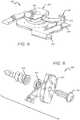
- FIG. 5is a front-side perspective view of a surface mounting mechanism that can be utilized with lighting systems according to the present disclosure
- FIG. 6is an exploded view of a surface mounting mechanism that can be utilized with lighting systems according to the present disclosure
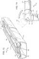
- FIG. 7is an exploded view of an embodiment of a lighting system according to the present disclosure.
- FIG. 8is another exploded view of the embodiment of a lighting system shown in FIG. 7 ;
- FIG. 9is a bottom perspective view of an embodiment of a lighting system according to the present disclosure.
- FIG. 10is a front perspective view of a connection joint that can be utilized with lighting systems according to the present disclosure.
- FIG. 11is a partial bottom view of body components that can be utilized with lighting systems according to the present disclosure.
- FIG. 12is a bottom perspective view of an embodiment of a lighting system according to the present disclosure.
- FIG. 13is a bottom perspective view of an embodiment of a lighting system according to the present disclosure.
- FIG. 14is a top operational view of a connection joint that can be utilized with lighting systems according to the present disclosure.
- FIG. 15is a front perspective view of an embodiment of a lighting system according to the present disclosure.
- FIG. 16is an exploded view of the embodiment of a lighting system shown in FIG. 15 ;
- FIG. 17is a front perspective view of an embodiment of a lighting system according to the present disclosure.
- FIG. 18is an exploded view of the embodiment of a lighting system shown in FIG. 17 ;
- FIG. 19is a front sectional view of an embodiment of a lighting system according to the present disclosure.
- FIG. 20is a front sectional view of an embodiment of a lighting system according to the present disclosure.
- the present disclosureis directed to different embodiments of lighting systems comprising one or more body components that can connect to a surface and be modularly arranged into desired lighting arrangement patterns.
- these lighting systemscan connect to existing surface grid systems, such as a ceiling T-bar grid and can comprise or not comprise modular components.
- devices according to the present disclosurecomprise at least one body component and at least one lighting element.
- the body componentcan be made of various materials including but not limited to: metals, plastics, acrylics, resins, Poly(methyl methacrylate) (PMMA), polycarbonate (PC), and materials known in the art to provide a desirable effect on emitted light; the body component can also comprises an alloy of or combination of one or more of these materials.
- the body componentcan be formed in a number of different ways including but not limited to machining, molding (such as injection molding), extrusion and co-extrusion.
- the body componentcan comprise a lens which can comprise transparent, translucent, diffusive and/or opaque portions.
- the lenscan be arranged to diffuse, magnify, or otherwise alter light output.
- the lenscan be made of the same material as the body component or can be made from a different material and integrated into the body component, for example via a co-extrusion process.
- the lenscan also be a separate physical component connected to the body.
- the lenscan comprise additional structures and materials or can be treated with various processes to allow the lens to alter the color of emitted light, with some embodiments comprising wavelength-altering materials such as phosphors.
- the lenscan comprise light scattering particles and can be structured or patterned to increase light extraction.
- Light altering properties, such as diffusive propertiescan also be imparted to the lens by physically roughening the surface of the lens, for example, via a machining process.
- the lighting elementscan comprise, for example, one or more LEDs, one or more LED packages, LED arrays, and LED-based light engines.
- Many different LEDscan be utilized with lighting elements according to the present disclosure.
- the LEDscan comprise highly efficient LED packages that are capable of operating at lower drive signals than many conventionally used LEDs. Since the current needed to drive such highly efficient LEDs can be lower, the power in each LED can also be lower. Multiple LEDs can be used to achieve the same output as fewer LEDs with a higher current. Examples of such highly efficient LEDs are described in detail in U.S. patent application Ser. Nos. 13/649,052, 13/649,067 and 13/770,389, all of which are assigned to Cree, Inc., which are hereby incorporated herein in their entirety by reference, including the drawings, charts, schematics, diagrams and related written description.
- the highly efficient LED packageshave a greater LED area per package footprint, which can allow for higher packing density. In many applications, this allows for driving the same area of LED packages with a lower drive signal to achieve the same emission intensity. This can result in greater emission efficiency. In other embodiments, the same drive current can be used, and the LED packages that can be utilized with the present invention can be used to generate higher emission intensity. These embodiments provide the flexibility of providing LED package emission with high luminous flux, or with lower luminous flux at greater efficiency.
- Lighting elements utilized in embodiments according to the present disclosurecan be connected to a printed circuit board (“PCB”).
- the PCBcan be connected to the body component in various ways, including but not limited to using adhesives and using securing mechanisms integrated with the body component.
- An alternative to utilizing a printed circuit boardis to utilize a conductive element arrangement.
- Such a conductive element arrangementcan include, for example, copper wire, conductive rails, magnet wire, non-conductive materials selectively coated with conductive materials, flattened braided wire and flex circuits on polyamide film.
- Lighting systems according to the present disclosurecan further comprise connection joints which allow for multiple body components to connect to one another.
- connection jointsenable the lighting systems to be modular and able to be configured with multiple body components in various arrangements depending on the desired lighting profile in a given space.
- these connection jointsare flexible and/or comprise moving components, such as a ball and socket, hinge or rotational joint portion.
- the body componentcan further comprise a mounting mechanism.
- This mounting mechanismcan connect the body component to a surface such as a ceiling or a wall, for example by connecting to an existing surface grid, such as a ceiling T-bar grid.
- the mounting mechanismcan be configured to connect to a standard T-bar grid structure.
- the mounting mechanismcan be part of the body component itself or can be connected to the body by a mounting mechanism connection feature.
- the body componentitself can connect to the mounting surface or can connect to the mounting surface through the intermediate mounting mechanism.
- inventionsrefers to any one of the embodiments of the invention described herein, and any equivalents.
- reference to various feature(s) of the “invention,” “device,” “method,” “present invention,” “present device” or “present method” throughout this documentdoes not mean that all claimed embodiments or methods must include the referenced feature(s).
- first, second, etc.may be used herein to describe various elements or components, these elements or components should not be limited by these terms. These terms are only used to distinguish one element or component from another element or component. Thus, a first element or component discussed below could be termed a second element or component without departing from the teachings of the present invention.
- the term “and/or”includes any and all combinations of one or more of the associated list items.
- the term “lighting element”refers to any structure that can emit light in response to an electrical signal and includes LEDs and LED devices containing one or more LEDs arranged into an array or incorporated into a light engine.
- Embodiments of the inventionare described herein with reference to different views and illustrations that are schematic illustrations of idealized embodiments of the invention. As such, variations from the shapes of the illustrations as a result, for example, of manufacturing techniques and/or tolerances are expected. Embodiments of the invention should not be construed as limited to the particular shapes of the regions illustrated herein but are to include deviations in shapes that result, for example, from manufacturing.
- FIG. 1shows a lighting system 100 , comprising a body component 102 , connected to an existing ceiling T-grid 104 .
- Lighting system 100is shown here with two end portions 106 .
- End portions 106correspond to where one body component 102 ends and can comprise a number of different structures such as endcaps or connection joints.
- Connection jointscan include singular connection joints, which are arranged such that additional body components can connect to body component 102 .
- This type of connection jointis referred to as a singular connection joint or a “singular connector” as it allows connection to only one other body component (two components total).
- connection jointscan allow for a straight connection of multiple body components.
- T-connection joints, quad connection joints and moveable connection jointsare further types of connection joints that will be discussed further below.
- lighting system 100fits over the existing T-bar grid structure.
- body 102can fit over an existing track lighting arrangement. It is understood that body 102 can also attach to many different surfaces including but not limited to ceiling, walls, floors, furniture, household appliances, other lighting systems and/or existing support or grid structures.
- connection joints according to this present disclosurecan be separate structures connected to a body component or can be integrated into the body component or be part of the body component itself. These connection joints can comprise different amounts of openings, some of which are described herein and can facilitate and enable the formation of various types of desired arrays.
- body component 102 in FIG. 1is shown to be a cylindrical shape, it is understood that body components according to the present disclosure can comprise many different shapes.
- such body componentscan be the shape of any regular polygon (e.g. square, rectangular, circular, triangular) or can comprise any number of irregular shapes that would achieve a desired output beam profile of emitted light.
- a portion of the body, or its entirety,can comprise a lens, and that lenses according to the present disclosure can comprise any number of shapes as well.
- FIG. 2shows a lighting system 150 , comprising a body component 152 , a lens component 154 , a lighting element 156 (the lighting element comprising at least one LED 158 and a PCB 160 ), a lighting element securing mechanism 162 (which secures PCB 160 into a desired position), a free space portion 164 , and surface mounting mechanism 166 , which connects lighting system 150 to T-bar 168 .
- lighting system 150directly connects to the T-bar 168 of an existing T-bar ceiling grid and does not substantially extend past ceiling tiles 170 into the ceiling plenum space.
- lens component 154is a separate structure from body component 152 , although it is understood, as discussed above, that the lens component 154 can be integrated with body 152 , for example, utilizing an extrusion process, or the body itself can be the lens component.
- Lens component 154can be connected to body component 152 at a connection point 172 .
- connection featurescan be utilized including but not limited to a living hinge, an adhesive compound, soldering, various means of permanent attachment and a snap-fit structure (wherein a structure on lens component 154 can interact or mate with a corresponding structure on body component 152 ).
- FIG. 2depicts surface mounting mechanism 166 as an integrated portion of body 152 that can grip or clip to T-bar 168 , however it is understood that mounting mechanism 166 can comprise several different mounting mechanisms as discussed above, including but not limited to clip-based structures, hook and loop based structures and complimentary surface based structures.
- mounting mechanism 166can be a separate structure to body 152 and be directly mounted to a surface, such as T-bar 168 .
- Body 152can then comprise a structure to connect to the mounting mechanism 166 and thus be connected to T-bar 168 through the intermediate mounting mechanism.
- lighting system 150is comprised of a light weight material so that the body can be held in place by the weight of the ceiling tile, essentially by having a portion of mounting mechanism 166 sandwiched between the T-bar 168 and a ceiling tile 170 , as is shown in FIG. 2 at point 174 .
- Free space 164can house various connection materials such as wires and leads as well as various electrical or electronic components.
- connection materialssuch as wires and leads as well as various electrical or electronic components.
- current and voltage converterscan be included in order to condition an electrical signal from a remote power supply to the input voltage and current to drive the appropriate design voltage and current of the LED circuit.
- Free space 164can comprise various internal structures such as tabs, hooks and other securing mechanisms to organize and secure stored connection materials and components.
- Lighting element securing mechanism 162can comprise various structures to secure the lighting element into place.
- PCB 156is held in between a top portion 176 and a base portion 178 of lighting element securing mechanism 162 .
- Lighting element securing mechanism 162can be formed integrally with the body component 152 during formation of the body component 152 .
- the top portion 176 of lighting element securing mechanism 162can also be made reflective, for example, reflective white, in order to improve light extraction of lighting system 150 .
- FIG. 3shows a lighting system 200 , similar to lighting system 150 in FIG. 2 above, wherein the corresponding disclosure is incorporated into the present embodiment.
- Lighting system 200comprises a body component 202 , a lens component 204 , a lighting element 206 (the lighting element comprising at least one LED 208 and a PCB 210 ), a lighting element securing mechanism 212 (which secures PCB 210 into a desired position), and surface mounting mechanism 214 , which connects lighting system 200 to T-bar 216 .
- Lens 204is shown connected to body 202 via a snap-fit connection 218 , although other connections as mentioned above can be utilized, lens component 204 can be formed integral to body component 202 , or body component 202 can itself be the lens component. Lens 204 is shown with an irregular shape comprising winged portions 220 . Winged portions 220 can be arranged to further direct emitted light in a desired output profile and can also comprise opaque portions or otherwise be arranged to conceal the presence of surface mounting mechanism 214 for aesthetic purposes. Although a linear form factor is represented in the current embodiment, additional shapes, such as, round, square, oval, and rectangular are also envisioned for specific applications.
- Surface mounting mechanism 214is an intermediate mounting mechanism in that body component 202 connects to surface mounting mechanism 214 which in turn connects to T-bar 216 , rather than body component 202 connecting to T-bar 216 directly itself.
- the intermediate mounting mechanismcan be arranged to facilitate manual operation of the position of a body component in relation to a mounting surface.
- the intermediate mounting mechanismcan be arranged such that a body component can be freely connected and removed from a mounting surface, for example to redesign a lighting arrangement or to replace or repair an existing lighting arrangement.
- the surface mounting mechanismcomprises at least two portions, a body component connecting portion 222 (which connects to body 202 ) connected to a surface connecting portion 224 (which connects to T-bar 216 ).
- body 202can comprise surface mounting mechanism gripping portions 226 which can connect to body component connection portion 222 , for example, by comprising a corresponding structure that can interact or mate with a structure on body component connection portion 222 .
- body component connecting portion 222comprises a cam lock and surface connection portion comprises a clip mechanism.
- the cam lock and clip mechanismcan interact as a knock-down or conformat fastener.
- These types of fastenerstypically comprise a cam dowel which can be locked by a cam lock installed in adjacent members.
- Body component connecting portion 222 and surface connecting portion 224can be brought closer together, and the joint tightened, by turning the cam lock portion 222 .
- Lighting systems according to the present disclosurecan comprise a variety of lens and body dimensions.
- FIG. 4shows a comparison between embodiments of a lighting system 250 and another larger lighting system 300 , similar to the embodiment shown in FIG. 3 , wherein the corresponding disclosure is incorporated into the present embodiment.
- Lighting system 250comprises a body component 252 and a lens component 254 and lighting system 300 comprises a body component 302 and a lens component 304 .
- Lighting system 250 and lighting system 300are similar however, they comprise different dimensions and slight alterations in body component shape to accommodate for these different dimensions.
- Lighting system 250has a height (h1) of 1.02 inches and it has a width (w1) of 1.5 inches.
- Lighting system 300has a height (h2) of 1.18 inches and it has a width (w2) of 2.35 inches.
- the smaller size (lighting system 250 )has an advantage of being able to blend in with a typical ceiling T-grid more closely in relation to the size of the grid. Although there are arrangements in which the larger size embodiment would be preferred.
- FIG. 5shows an intermediate cam lock style mounting mechanism 350 , similar to surface mounting mechanism 214 in FIG. 3 above.
- Surface mounting mechanism 350comprises two portions, a body component connecting portion 352 (which connects to body component of a lighting system) and a surface connecting portion 354 (which connects a desired mounting surface).
- Body component connection portion 352has a structure such that it can facilitate connection to a lighting system body component, for example, in the embodiment shown, body component connection portion 352 comprises ridged structures 356 which can interact or mate with a corresponding structure on a body component of a lighting system.
- a body componentcan connect to body component connection portion 352 which in turn can connect to surface connecting portion 354 already connected to a mounting surface.
- the body componentcan be secured into place by rotating either the body component itself or the body component connection portion 352 , for example by manually operating the handle portion 357 , such that the connection between the body component connection portion 352 and the surface connecting portion 354 is tightened.
- Surface connecting portion 354has a structure such that it can facilitate connection to a to a desired mounting surface, for example, in the embodiment shown, surface component connection portion 354 comprises clip structures 358 which can interact or mate with a corresponding structure on a surface, such as a T-bar in a surface grid.
- Body component connecting portion 352 and a surface connecting portion 354are connected together at point 360 via a cam lock mechanism as is describe above and the connection can be tightened by rotating body component connection portion 352 .
- a hook and loop connection(such as Velcro®) can be utilized (especially in embodiments where a body component comprises a light weight material).
- One-half of the hook and loop bondcan be connected to, either temporarily or permanently, a body component and the other half connected to, either temporarily or permanently, a mounting surface such as a wall or a ceiling, such that the body component can be connected to the mounting surface.
- Other complimentary structurescan be utilized as surface mounting mechanisms such that one-half of a mounting mechanism is connected to a body component and the another half is connected to a mounting surface, such that the two halves can be connected together in order to connect the body to the mounting surface.
- Complimentary magnetic structurescan also be utilized in this manner.
- multiple intermediate structurescan be used such that a body component can be connected to a surface mounting mechanism which in turn is connected to one or more additional surface mounting mechanisms, which is ultimately connected to a mounting surface.
- Other surface mounting mechanismscan be utilized including but not limited to temporarily or permanent adhesives, glues, cements, single- or double sided adhesive strips or structures (which can also be designed to interact with or mate with portions of a body component), hooks, screws and fasteners.
- the mounting mechanismcan be configured such that a body component can be mounted to a surface that is not an existing surface grid system (such as a T-bar grid or a track lighting arrangement), for example a flat ceiling or wall.
- a body componentcan be mounted to a surface that is not an existing surface grid system (such as a T-bar grid or a track lighting arrangement), for example a flat ceiling or wall.
- such lighting systemscan comprise manually operable mounting mechanisms allowing for body components to be freely removed and/or replaced from a mounting surface as needed. Any of the above surface mounting mechanisms can be adapted for this purpose.
- FIG. 6shows a mounting mechanism 400 , comprising a body component connecting portion 402 (which connects to body component of a lighting system) and a surface connecting portion 404 (which connects a desired mounting surface).
- Body component connecting portion 402is similar to body component connecting portion 354 above, however, surface connecting portion 404 is configured to serve as an anchor in a surface, such as a ceiling or wall (e.g. drywall, plaster, etc.). Surface connecting portion 404 can penetrate the mounting surface and serve as an anchor allowing body component connecting portion 402 (and a connected body component) to connect to surface connecting portion 404 . The two structures 402 , 404 can then be further tightened together and secured via retaining washer 406 and machine screw 408 .
- FIG. 7shows a lighting system 450 , similar to lighting system 200 in FIG. 3 above, wherein the corresponding disclosure is incorporated into this embodiment.
- Lighting system 450comprises a body component 452 , a lens component 454 , a lighting element 456 (the lighting element comprising at least one LED 458 and a PCB 460 ), and a surface mounting mechanism 462 , which connects lighting system 450 to T-bar 464 .
- ceiling tile 465is also shown.
- Lighting system 450is provided power by a remote power supply 466 , which can be connected to the lighting element 456 by electrical connection pathway 468 , which can be any electrically conductive wire, cable, trace or conduit, for example, a CAT-5 cable.
- the remote power supply 466can be positioned in the ceiling, connected to an existing surface grid (as shown), or can be positioned elsewhere, for example in an inconspicuous corner of the room.
- the remote power supply 466can be disguised to look like or blend in with common objects for aesthetic purposes.
- other electronic componentscan be housed inside body 452 , for example voltage and current converters in order to further condition the electrical signal from remote power supply 466 .
- FIG. 8is another view of lighting system 450 comprising body component 452 , lens component 454 , lighting element 456 , and surface mounting mechanism 462 , which connects lighting system 450 to T-bar 464 .
- This viewdepicted in FIG. 8 , shows surface mounting mechanisms 462 attached to T-bar 464 .
- This viewalso better shows the endcaps 470 , which can be used to close off ends of the lighting system if no connections to additional body components are desired. Endcaps 470 can provide additional protection of internal components.
- FIG. 9shows the outer portion of a lighting system 500 , connected to a T-bar grid 501 , which comprises a body component 502 and two additional body components 504 , 506 connected together by a connection joint 508 .
- connection joint 508is a T-connection joint or “T-connecter,” which can connect up to three separate body components.
- FIG. 9depicts connection joint 508 connecting body component 502 with the other body components 504 , 506 .
- FIG. 9depicts connection joint 508 connecting body component 502 with the other body components 504 , 506 .
- FIG. 9further depicts a surface mount supporting structure 510 , which can connect to a surface, such as T-grid 501 , as shown, and provide support and mounting stability for longer body components, such as body component 502 .
- a singular connection jointjoining two linear sections and connected to the mounting surface, can be used in lieu of or in addition to surface mount supporting structure 510 .
- Connection jointsare further detailed in FIG. 10 , which shows a T-connection joint 550 , similar to connection joint 508 in FIG. 9 above, wherein the corresponding disclosure is incorporated into this embodiment.
- Connection joint 550can be made from the same materials listed above for the body components or any other suitable rigid or otherwise sturdy material that is known in the art.
- Connection joints according to the present disclosurecan be arranged such that body components can connect to the connection joint, for example, by having openings 552 that correspond in shape or size to a part of a body component or by comprising various body component-accepting structures that facilitate connection to body components. For example grooved structures 554 , which can correspond to other structures on a body component.
- Connection joint 550can further comprise electrical or electronic components which are housed in an electronic component housing 556 which can also utilize grooved structures 554 to secure the electronic component housing in connection joint 550 .
- Electronic component housing 556can house various electrical or electronic components, such as voltage and current converters, to condition an electrical signal from a remote power supply to the input voltage and current to drive the appropriate design voltage and current of the LED circuit.
- the electronic component housingcan provide electrical connection to lighting elements within connected body components at all openings 552 , for example through utilizing electrical connection holes 558 , which allow access to the internal electronic components that are housed within electronic component housing 556 .
- the electronic component housing 556can comprise an opaque material to hide the appearance of the electronic components therein for aesthetic purposes.
- the top surface 560 of connection joint 550can comprise the same physical properties of an attached body component or can comprise different ones.
- the top surface 560comprises a diffuse material.
- top surface 560can be translucent, diffuse, opaque or reflective or a combination thereof.
- FIG. 11shows a partial view of body components 600 that can be utilized with embodiments incorporating features of the present invention.
- multiple body componentscan comprise mitered ends 602 which allow for tighter fitting into connection joint intersections. These mitered ends also allow for more continuous appearance of illuminated shapes without dark ends/corners.
- FIG. 12shows a lighting system 650 comprising four body components 652 , 654 , 656 , 658 connected together at a quad connection joint 670 .
- Quad-connection joint 670is similar to T-connection joint 550 in FIG. 10 above and can comprise the same features, however, unlike T-connection joint 550 , quad-connection joint 670 , has four opening portions rather than three, allowing four body components to be connected together as is depicted in FIG. 12 .
- connection jointscan be utilized according to the present disclosure with variable numbers of openings (e.g. five or six openings).
- the various connection jointscan be mixed and matched with body components to provide increased flexibility in designing lighting arrangements for a space.
- FIG. 13shows a lighting system 700 comprising six separate body components 702 , 704 , 706 , 708 , 710 , 712 , which are connected together by a T-connection joint 714 and a quad connection joint 716 .
- Additional supportcan be provided to the longer body components (i.e. body component 708 ) by surface mount supporting structure 718 , which is similar to surface mount supporting structure 510 in FIG. 9 above.
- connection joints incorporating features of the present inventioncan also comprise movable features, allowing for even more customization of lighting system output.
- FIG. 14shows a movable connection joint 750 , that comprises two openings that allows it to connect to a first body component 752 and a second body component 754 .
- the connection joint 750comprises a stationary portion 756 connected to a movable portion 758 .
- Various rotation mechanismscan be utilized that allow the body component connection portions of connection joint 750 to move in relation to the other one.
- the moveable portion 758is arranged to pivot along an axis point 760 such that body component 754 can move to one or more alternative positions 762 .
- the rotation of the jointcan be restricted, for example to a field of 180 degrees through various means including fin structures 764 that can abut against portions of a body component or joint 750 and restrict further movement.
- Moveable connection joint 750can be designed such that there are several preset positions in which body component 754 can occupy or can allow for free range of motion or restriction of motion to a preset range.
- Moveable connection joint 750can also further comprise a locking mechanism that can fix the position of body component 754 in a desired place in embodiments allowing a full range of motion.
- a moveable connection jointneed not be restricted to rotational movement, but can comprise a number of moveable joint arrangements including but not limited to: a ball and socket joint arrangement, a hinge or living hinge arrangement and a vertical rotational movement arrangement.
- the connection jointcan simply be made of a flexible material that allows for connected body components to stretch, twitch or otherwise orientate themselves in various spatial ways in relation to one another.
- different moveable joint structuresare possible including moveable joints with more than two openings wherein each opening can be arranged to be moveable in relation to one or more of the other openings, for example a moveable t-connector joint or a moveable quad-connector joint.
- FIGS. 15 and 16show an embodiment of a lighting system 800 in a perspective view 801 and an exploded view 803 .
- Lighting system 800is similar to lighting system 200 in FIG. 3 above, wherein the corresponding disclosure is incorporated into the present embodiment.
- Lighting system 800comprises a body component 802 , a lens component 804 , a lighting element 806 (which can comprise multiple lighting element PCB platforms as shown), a lighting element securing mechanism 808 , and surface mounting mechanism 810 , which connects lighting system 800 to a mounting surface.
- Lighting system 800differs from lighting system 200 in that the surface mounting mechanism 810 is a single element, rather than the two-part cam lock and clip element of lighting system 200 .
- the clip portion 812 of surface mounting mechanism 810can attach to a surface such as a T-bar and the base portion 814 can slide into receiving grooves 816 on body component 802 .
- Surface mounting mechanism 810can be arranged with a rotational element 818 , which can allow the clips to be rotated into place.
- Lighting system 800can further comprise a support joint 820 to provide further structural stability to the lighting system 800 .
- FIGS. 17 and 18show an embodiment of a lighting system 900 in a perspective view 901 and an exploded view 903 .
- Lighting system 900similar to lighting system 200 in FIG. 3 above, wherein the corresponding disclosure is incorporated into the present embodiment.
- Lighting system 900comprises a body component 902 , a lens component 904 , a lighting element 906 (which can comprise multiple lighting element PCB platforms as shown), a lighting element securing mechanism 908 , and surface mounting mechanism 910 , which connects lighting system 900 to a mounting surface.
- Lighting system 900differs from lighting system 200 in that the surface mounting mechanism 910 is a two piece complimentary structure, rather than the two-part cam lock and clip element of lighting system 200 .
- the two-piece complimentary structure 910can comprise any complimentary structure that encourages connection of the two pieces. One piece is connected to the lighting system 900 and the other piece is connected to a mounting surface. Examples of complimentary two-piece structures include adhesives, snap-fit structures and hook and loop structures.
- Lighting system 900can further comprise a support joint 912 to provide further structural stability to the lighting system 900 .
- FIG. 19depicts a lighting system 1000 , similar to lighting system 200 in FIG. 3 above, wherein the corresponding disclosure is incorporated into the present embodiment.
- Lighting system 1000comprises a body component 1002 , a lens component 1004 , a lighting element 1006 (the lighting element comprising at least one LED 1008 and a PCB 1010 ), a lighting element securing mechanism 1012 (which secures PCB 1010 into a desired position), and surface mounting mechanism 1014 , which connects lighting system 1000 to a mounting surface.
- body component 1002 and lens 1004are extruded as one element of the same material or co-extruded such that body component 1002 and lens component 1004 are integral to one another but comprise different materials.
- body component 1002can be co-extruded with lens component 1004 such that lens component 1004 comprises a translucent material and body component 1004 comprises a reflective material (for example to make the top portion of lighting element securing mechanism 1012 reflective).
- Body component 1002can also be extruded as a single piece of material such that the body component itself comprises the lens component 1004 .
- lens component 1004is co-extruded with body component 1002 such that lens 1004 is connected to body 1002 by a living hinge.
- living hinge arrangementsare described in detail in U.S. patent application Ser. No. 13/782,820 to Mark Dixon, et al., entitled Integrated Linear Light Engine, which is hereby incorporated in its entirety by reference into the present application, including the drawings, charts, schematics, diagrams and related written description.
- FIG. 20depicts a lighting system 1050 , similar to lighting system 200 in FIG. 3 above, wherein the corresponding disclosure is incorporated into the present embodiment.
- Lighting system 1050comprises a body component 1052 , a lens component 1054 , a lighting element 1056 (the lighting element comprising at least one LED 1058 and a PCB 1060 ), a lighting element securing mechanism 1062 (which secures PCB 1060 into a desired position), and surface mounting mechanism 1064 , which connects lighting system 1050 to a mounting surface.
- body component 1052 and lens component 1054are manufactured separately and then later connected.
- the connectioncan be permanent or temporary.
- body component 1052is connected to lens component 1054 via a snap-fit structure arrangement.
- snap fit structure arrangementsas well as other connection arrangements are described in detail in U.S. patent application Ser. No. 13/782,820 to Mark Dixon, et al., entitled Integrated Linear Light Engine, which is hereby incorporated in its entirety by reference into the present application, including the drawings, charts, schematics, diagrams and related written description.
Landscapes
- Engineering & Computer Science (AREA)
- General Engineering & Computer Science (AREA)
- Non-Portable Lighting Devices Or Systems Thereof (AREA)
- Arrangement Of Elements, Cooling, Sealing, Or The Like Of Lighting Devices (AREA)
Abstract
Description
Claims (17)
Priority Applications (2)
| Application Number | Priority Date | Filing Date | Title |
|---|---|---|---|
| US13/910,486US10788176B2 (en) | 2013-02-08 | 2013-06-05 | Modular LED lighting system |
| US17/003,240US11162655B2 (en) | 2012-11-08 | 2020-08-26 | Modular LED lighting system |
Applications Claiming Priority (3)
| Application Number | Priority Date | Filing Date | Title |
|---|---|---|---|
| US13/763,270US10309627B2 (en) | 2012-11-08 | 2013-02-08 | Light fixture retrofit kit with integrated light bar |
| US13/782,820US9482396B2 (en) | 2012-11-08 | 2013-03-01 | Integrated linear light engine |
| US13/910,486US10788176B2 (en) | 2013-02-08 | 2013-06-05 | Modular LED lighting system |
Related Parent Applications (1)
| Application Number | Title | Priority Date | Filing Date |
|---|---|---|---|
| US13/782,820Continuation-In-PartUS9482396B2 (en) | 2012-11-08 | 2013-03-01 | Integrated linear light engine |
Related Child Applications (1)
| Application Number | Title | Priority Date | Filing Date |
|---|---|---|---|
| US17/003,240ContinuationUS11162655B2 (en) | 2012-11-08 | 2020-08-26 | Modular LED lighting system |
Publications (2)
| Publication Number | Publication Date |
|---|---|
| US20140226316A1 US20140226316A1 (en) | 2014-08-14 |
| US10788176B2true US10788176B2 (en) | 2020-09-29 |
Family
ID=51297303
Family Applications (2)
| Application Number | Title | Priority Date | Filing Date |
|---|---|---|---|
| US13/910,486ActiveUS10788176B2 (en) | 2012-11-08 | 2013-06-05 | Modular LED lighting system |
| US17/003,240ActiveUS11162655B2 (en) | 2012-11-08 | 2020-08-26 | Modular LED lighting system |
Family Applications After (1)
| Application Number | Title | Priority Date | Filing Date |
|---|---|---|---|
| US17/003,240ActiveUS11162655B2 (en) | 2012-11-08 | 2020-08-26 | Modular LED lighting system |
Country Status (1)
| Country | Link |
|---|---|
| US (2) | US10788176B2 (en) |
Cited By (3)
| Publication number | Priority date | Publication date | Assignee | Title |
|---|---|---|---|---|
| US20220372752A1 (en)* | 2021-03-30 | 2022-11-24 | Fusion Optix, Inc. | Edgelit multifunctional lighting assembly for use in a suspended ceiling system |
| US11788719B1 (en)* | 2022-08-19 | 2023-10-17 | Shinegrow (Xiamen) Lighting Technology Co., LTD. | Water-proof modularized lighting device |
| US12372220B2 (en)* | 2025-01-15 | 2025-07-29 | Cr Lighting Technology Co., Ltd. | Cabinet light with diffuser and reflector behind L-shaped lamp shade |
Families Citing this family (38)
| Publication number | Priority date | Publication date | Assignee | Title |
|---|---|---|---|---|
| US8704262B2 (en)* | 2011-08-11 | 2014-04-22 | Goldeneye, Inc. | Solid state light sources with common luminescent and heat dissipating surfaces |
| CA2947996A1 (en) | 2014-05-08 | 2015-11-12 | George R. Bailey | Led lighting systems and methods of installation |
| US10344476B2 (en)* | 2015-09-21 | 2019-07-09 | Abl Ip Holding Llc | Lighting fixtures and methods for grid ceiling systems |
| US10499487B2 (en) | 2015-10-05 | 2019-12-03 | Scalia Lighting Technologies LLC | Light-emitting diode (LED) lighting fixture solutions and methods |
| US20170175961A1 (en)* | 2015-12-18 | 2017-06-22 | Applied Electronic Materials, LLC | Lighting system having structural components with integrated lighting |
| US10941926B2 (en) | 2015-12-18 | 2021-03-09 | Applied Electronic Materials, LLC | Modular lighting system including light modules with integrated LED units |
| US11274823B1 (en) | 2016-03-02 | 2022-03-15 | Cooledge Lighting, Inc. | Lighting systems incorporating connections for signal and power transmission |
| US11585501B2 (en) | 2016-10-20 | 2023-02-21 | Axis Lighting Inc. | Couplers for light fixtures |
| USD1088336S1 (en) | 2016-10-20 | 2025-08-12 | Axis Lighting Inc. | Light fixture |
| USD911592S1 (en) | 2016-10-20 | 2021-02-23 | Axis Lighting Inc. | Light fixture segment |
| US10215380B2 (en) | 2016-10-20 | 2019-02-26 | Axis Lighting Inc. | Couplers for light fixtures |
| US12085258B2 (en) | 2016-10-20 | 2024-09-10 | Axis Lighting Inc. | Couplers for light fixtures |
| CN108954132A (en)* | 2016-10-27 | 2018-12-07 | 新昌县鼎瑞科技有限公司 | High stability pendent lamp easy to assemble |
| US10077877B2 (en)* | 2016-11-22 | 2018-09-18 | Apogee Lighting Holdings, Llc | Lighting device with integral acoustic dampening |
| US11118765B1 (en) | 2020-03-04 | 2021-09-14 | Axis Lighting, Inc. | Luminaire structure |
| US11608967B2 (en) | 2020-03-04 | 2023-03-21 | Axis Lighting Inc. | Luminaire structure |
| US11199002B2 (en) | 2017-07-14 | 2021-12-14 | Axis Lighting Inc. | Acoustic panel |
| US12241615B1 (en) | 2017-06-19 | 2025-03-04 | Axis Lighting Inc. | Luminaire structure |
| US11635190B2 (en) | 2017-07-14 | 2023-04-25 | Axis Lighting Inc. | Acoustic luminaire structure |
| US11079077B2 (en) | 2017-08-31 | 2021-08-03 | Lynk Labs, Inc. | LED lighting system and installation methods |
| US10190738B1 (en) | 2017-09-27 | 2019-01-29 | Inter-Lux, Inc. | Luminaires and light source retention components |
| US10443823B2 (en)* | 2018-01-31 | 2019-10-15 | Axis Lighting Inc. | Mount interace for light fixtures |
| US11384927B2 (en)* | 2018-01-31 | 2022-07-12 | Axis Lighting Inc. | Conduit access for light fixtures |
| CA2999308C (en)* | 2018-03-26 | 2020-07-14 | Xianwen Xiong | Ceiling mountable led light fixture with accessible cct selectable switch |
| US11015787B2 (en) | 2018-04-06 | 2021-05-25 | Certainteed Ceilings Corporation | Lighting fixtures and systems including them, lighting assembly attachment system, and methods of installing same |
| USD898982S1 (en) | 2018-04-06 | 2020-10-13 | Certainteed Ceilings Corporation | Lighting fixture |
| GB2562195B (en)* | 2018-08-29 | 2019-07-03 | Thorpe F W Plc | Ceiling Luminaire |
| US11092319B2 (en) | 2018-12-21 | 2021-08-17 | Axis Lighting Inc. | Mount interface for light fixtures |
| AU2019200784B2 (en)* | 2019-02-05 | 2025-08-14 | Efficient Lighting Systems Pty. Ltd. | Lighting assembly |
| US10663148B1 (en)* | 2019-09-16 | 2020-05-26 | Elemental LED, Inc. | Modular channel for linear lighting |
| US10724719B1 (en) | 2019-09-16 | 2020-07-28 | Elemental LED, Inc. | Channel system for linear lighting |
| US10724720B1 (en) | 2019-09-16 | 2020-07-28 | Elemental LED, Inc. | Multi-purpose channels for linear lighting |
| US11118752B2 (en) | 2020-01-27 | 2021-09-14 | Elemental LED, Inc. | Flexible cover for linear lighting channels |
| JP7093023B2 (en)* | 2020-03-27 | 2022-06-29 | 日亜化学工業株式会社 | How to install lighting fixtures, lighting set, and mounting plate |
| US11255519B1 (en) | 2020-08-17 | 2022-02-22 | Klus, Llc | Dual extrusion system for led light fixture |
| USD986479S1 (en) | 2020-08-17 | 2023-05-16 | Klus, Llc | Extrusion for LED based lighting apparatus |
| EP4466489A1 (en) | 2022-01-21 | 2024-11-27 | Signify Holding B.V. | Bracket for linear luminaires |
| CN116182103B (en)* | 2023-04-25 | 2023-08-11 | 厦门普为光电科技有限公司 | Lighting device with anti-glare cover |
Citations (151)
| Publication number | Priority date | Publication date | Assignee | Title |
|---|---|---|---|---|
| US3589660A (en)* | 1970-03-05 | 1971-06-29 | Nat Service Ind Inc | Lighting fixture hanger |
| US4073108A (en)* | 1974-04-25 | 1978-02-14 | Williams Arthur C | Method and apparatus for rigidly interconnected ceiling and wall construction |
| US4118763A (en) | 1976-04-12 | 1978-10-03 | General Electric Company | Variable transmission prismatic refractors |
| US4300185A (en) | 1979-12-07 | 1981-11-10 | C. W. Cole & Company, Inc. | Light fixture unit for open plan office |
| US4464707A (en) | 1982-03-17 | 1984-08-07 | Louis Forrest | Lighting fixture |
| US4472767A (en) | 1981-12-23 | 1984-09-18 | Mcgraw-Edison Company | Reflector assembly for indirect or semi-indirect lighting fixture |
| US4946547A (en) | 1989-10-13 | 1990-08-07 | Cree Research, Inc. | Method of preparing silicon carbide surfaces for crystal growth |
| US5200022A (en) | 1990-10-03 | 1993-04-06 | Cree Research, Inc. | Method of improving mechanically prepared substrate surfaces of alpha silicon carbide for deposition of beta silicon carbide thereon and resulting product |
| US5335890A (en)* | 1992-07-20 | 1994-08-09 | Pryor Products, Inc. | Ceiling track mounting apparatus |
| USRE34861E (en) | 1987-10-26 | 1995-02-14 | North Carolina State University | Sublimation of silicon carbide to produce large, device quality single crystals of silicon carbide |
| US5530628A (en) | 1993-04-05 | 1996-06-25 | Peerless Lighting Corporation | Task light |
| US5653412A (en)* | 1994-11-14 | 1997-08-05 | Cooper Industries, Inc. | Track mounting clip for a track lighting system |
| US5687527A (en)* | 1996-02-22 | 1997-11-18 | Clestra Cleanroom (S.A.) | Suspended ceiling for cleanrooms |
| US5690415A (en) | 1995-11-29 | 1997-11-25 | Stylmark, Inc. | Display light |
| US5823663A (en) | 1996-10-21 | 1998-10-20 | National Service Industries, Inc. | Fluorescent troffer lighting fixture |
| US5907218A (en) | 1996-12-09 | 1999-05-25 | The Whitaker Corporation | Fluorescent lighting assembly with integral ballast |
| US5951150A (en) | 1997-09-11 | 1999-09-14 | Eaton Corporation | Display system |
| US6190198B1 (en)* | 1996-03-21 | 2001-02-20 | Peter Ray | Electrical fittings for suspended ceilings |
| US6210025B1 (en) | 1999-07-21 | 2001-04-03 | Nsi Enterprises, Inc. | Lensed troffer lighting fixture |
| US20010048599A1 (en) | 2000-05-10 | 2001-12-06 | Jean-Marc Hess | Light distributor for a lighting device and lighting device and use of a lighting device |
| US6435697B1 (en) | 2001-02-02 | 2002-08-20 | Joseph E. Simmons | Exterior lighting system |
| US6536924B2 (en) | 2001-02-28 | 2003-03-25 | Jji Lighting Group, Inc. | Modular lighting unit |
| US6667451B1 (en) | 2003-03-20 | 2003-12-23 | Eaton Corporation | Push button assembly |
| US6739734B1 (en) | 2003-03-17 | 2004-05-25 | Ultimate Presentation Sytems, Inc. | LED retrofit method and kit for converting fluorescent luminaries |
| US20040240214A1 (en)* | 2003-05-28 | 2004-12-02 | Hubbell Incorporated. | Light fixture having air ducts |
| US20040252521A1 (en) | 2003-06-13 | 2004-12-16 | Finelite | Free-cavity, double-diffusing indirect lighting luminaire |
| US20050041418A1 (en) | 2003-08-19 | 2005-02-24 | Ben Fan | Neon light using a rope light as a light source |
| US6914194B2 (en) | 2003-10-29 | 2005-07-05 | Ben Fan | Flexible LED cable light |
| US20050146867A1 (en) | 2003-12-31 | 2005-07-07 | Kassay Charles E. | Fluorescent lighting fixtures with controlled uplight capability |
| CN1710323A (en) | 2004-06-18 | 2005-12-21 | 艾柯蒂布兰兹公司 | Light fixtures and lens assemblies for light fixtures |
| US20060050505A1 (en) | 2002-05-28 | 2006-03-09 | Kenall Manufacturing Company | Selectively-extendable modular lighting fixture and method |
| US7131747B1 (en) | 2003-12-29 | 2006-11-07 | Yates James P | Length adjustment device for illuminated fascia |
| US20060266955A1 (en) | 2005-05-24 | 2006-11-30 | Dubois Equipment Company, Inc. | Apparatus for curing a coating on a three-dimensional object |
| US20060278882A1 (en) | 2005-06-10 | 2006-12-14 | Cree, Inc. | Power lamp package |
| US7161554B2 (en)* | 2003-10-30 | 2007-01-09 | Cushcraft Corporation | System and method for securing an antenna |
| CN2872082Y (en) | 2006-01-18 | 2007-02-21 | 深圳市海洋王投资发展有限公司 | Efficient ceiling light of gymnasium |
| US7213940B1 (en) | 2005-12-21 | 2007-05-08 | Led Lighting Fixtures, Inc. | Lighting device and lighting method |
| US7217023B2 (en)* | 2002-08-01 | 2007-05-15 | Toyoda Gosei Co., Ltd. | Linear luminous body and linear luminous structure |
| US20070109330A1 (en) | 2001-05-09 | 2007-05-17 | Clairvoyante, Inc | Conversion of a sub-pixel format data to another sub-pixel data format |
| US7228253B2 (en) | 2004-08-19 | 2007-06-05 | Pacific Telescope Corp. | Instrument mounting system with dual encoders |
| US20070158668A1 (en) | 2005-08-25 | 2007-07-12 | Cree, Inc. | Close loop electrophoretic deposition of semiconductor devices |
| US20070171647A1 (en) | 2006-01-25 | 2007-07-26 | Anthony, Inc. | Control system for illuminated display case |
| US20070183148A1 (en) | 2004-06-18 | 2007-08-09 | Mayfield John T Iii | Light fixture |
| US7267461B2 (en) | 2004-01-28 | 2007-09-11 | Tir Systems, Ltd. | Directly viewable luminaire |
| US7303310B2 (en) | 2006-03-23 | 2007-12-04 | Opto Tech Corp. | Structure for a high efficiency and water-proof lighting device |
| WO2008003289A2 (en) | 2006-07-06 | 2008-01-10 | Osram Gesellschaft mit beschränkter Haftung | Illuminating system of flexible shape |
| US20080128723A1 (en) | 2006-12-04 | 2008-06-05 | Siew It Pang | Low Thermal Resistance High Power LED |
| US7387410B2 (en) | 2004-09-07 | 2008-06-17 | C.E.I.T. Corp. | Luminaire assembly and method |
| US20080173884A1 (en) | 2007-01-22 | 2008-07-24 | Cree, Inc. | Wafer level phosphor coating method and devices fabricated utilizing method |
| US20080179611A1 (en) | 2007-01-22 | 2008-07-31 | Cree, Inc. | Wafer level phosphor coating method and devices fabricated utilizing method |
| US20080258130A1 (en) | 2007-04-23 | 2008-10-23 | Bergmann Michael J | Beveled LED Chip with Transparent Substrate |
| US20080285267A1 (en) | 2007-04-10 | 2008-11-20 | Ledalite Architectural Products, Inc. | Light control device exhibiting batwing luminous intensity distributions in upper and lower hemispheres |
| US20080314944A1 (en) | 2007-06-21 | 2008-12-25 | Cheng-Yu Tsai | Assembly for fixing and connecting light bar lamp |
| US20090009999A1 (en) | 2007-07-06 | 2009-01-08 | Bily Wang | LED lamp structure and system with high-efficiency heat-dissipating function |
| US20090040782A1 (en) | 2007-08-08 | 2009-02-12 | Ledtech Electronics Corp. | Led lighting device |
| US20090046457A1 (en) | 2007-08-13 | 2009-02-19 | Everhart Robert L | Solid-state lighting fixtures |
| US7520636B2 (en) | 2005-11-11 | 2009-04-21 | Koninklijke Philips Electronics N.V. | Luminaire comprising LEDs |
| US7540627B2 (en)* | 2006-05-08 | 2009-06-02 | Innovative Lighting, Inc. | Channel light system with pivotable connector |
| US20090161356A1 (en) | 2007-05-30 | 2009-06-25 | Cree Led Lighting Solutions, Inc. | Lighting device and method of lighting |
| US20090184333A1 (en) | 2008-01-17 | 2009-07-23 | Foxsemicon Integrated Technology, Inc. | Light emitting diode device |
| US20090185379A1 (en) | 2008-01-23 | 2009-07-23 | Chia-Yi Chen | LED light device having heat dissipating structure |
| US20090207602A1 (en)* | 2005-09-06 | 2009-08-20 | Reed Mark C | Linear lighting system |
| US20090212304A1 (en) | 2008-02-22 | 2009-08-27 | Bily Wang | Led chip package structure with multifunctional integrated chips and a method for making the same |
| US20090224265A1 (en) | 2008-03-05 | 2009-09-10 | Bily Wang | LED chip package structure with a high-efficiency heat-dissipating substrate and method for making the same |
| US7591578B2 (en) | 2006-01-21 | 2009-09-22 | Hon Hai Precision Industry Co., Ltd. | Edge type backlight module having a reflective plate |
| US20090290345A1 (en) | 2008-05-20 | 2009-11-26 | Apl Ip Holding Llc | Enclosures for led circuit boards |
| US20090290348A1 (en) | 2006-04-16 | 2009-11-26 | Peter Van Laanen | Thermal Management Of LED-Based Lighting Systems |
| US20090296381A1 (en)* | 2008-06-01 | 2009-12-03 | Jack Dubord | Adjustable modular lighting system and method of using same |
| US7628506B2 (en) | 2005-10-03 | 2009-12-08 | Orion Energy Systems, Inc. | Modular light fixture with power pack and radiative, conductive, and convective cooling |
| US20100002426A1 (en) | 2008-06-25 | 2010-01-07 | Hubbell Incorporated | Multi-directional lighting fixture |
| US20100014289A1 (en) | 2007-06-13 | 2010-01-21 | ElectraLED Inc. | Multiple use LED light fixture |
| KR20100012997A (en)* | 2008-07-30 | 2010-02-09 | 한밭대학교 산학협력단 | Automatic toothpaste extruder |
| US7674005B2 (en) | 2004-07-29 | 2010-03-09 | Focal Point, Llc | Recessed sealed lighting fixture |
| US20100110701A1 (en) | 2008-10-30 | 2010-05-06 | Fu Zhun Precision Industry (Shen Zhen) Co., Ltd. | Led lamp |
| US7722220B2 (en) | 2006-05-05 | 2010-05-25 | Cree Led Lighting Solutions, Inc. | Lighting device |
| US20100128485A1 (en) | 2008-07-23 | 2010-05-27 | Ledtech Electronics Corp. | Custom assembly light-emitting module |
| US20100142205A1 (en) | 2008-12-08 | 2010-06-10 | Avx Corporation | Two part surface mount led strip connector and led assembly |
| US20100155763A1 (en) | 2008-01-15 | 2010-06-24 | Cree, Inc. | Systems and methods for application of optical materials to optical elements |
| US20100171404A1 (en) | 2009-01-07 | 2010-07-08 | Fu Zhun Precision Industry (Shen Zhen) Co., Ltd. | Led lamp |
| US7758207B1 (en) | 2009-03-17 | 2010-07-20 | Fu Zhun Precision Industry (Shen Zhen) Co., Ltd. | Lightweight LED lamp |
| US20100214770A1 (en)* | 2009-02-25 | 2010-08-26 | Anderson Kenneth E | Combination LED fixture and raceway |
| US20100220469A1 (en) | 2008-05-23 | 2010-09-02 | Altair Engineering, Inc. | D-shaped cross section l.e.d. based light |
| US7791061B2 (en) | 2004-05-18 | 2010-09-07 | Cree, Inc. | External extraction light emitting diode based upon crystallographic faceted surfaces |
| US20100259927A1 (en) | 2009-04-09 | 2010-10-14 | Chien Hsiao-Lou | Led lamp structure |
| US20100271804A1 (en) | 2009-04-22 | 2010-10-28 | Levine Jonathan E | Modular lighting device kit |
| US20100271825A1 (en) | 2009-04-23 | 2010-10-28 | Integrated Illumination Systems, Inc. | Systems and methods for sealing a lighting fixture |
| US20100328945A1 (en) | 2009-06-30 | 2010-12-30 | Fu Zhun Precision Industry (Shen Zhen) Co., Ltd. | Led lamp |
| US20110007514A1 (en) | 2008-05-09 | 2011-01-13 | Sloanled, Inc. | Low profile extrusion |
| US20110006688A1 (en) | 2008-02-26 | 2011-01-13 | Shim Hyun-Seop | Led lamp device |
| US20110013400A1 (en) | 2009-07-16 | 2011-01-20 | Japan Aviation Electronics Industry, Limited | Socket, circuit board assembly, and apparatus having the same |
| US20110028006A1 (en) | 2008-03-20 | 2011-02-03 | Ashok Deepak Shah | Conductive Magnetic Coupling System |
| CN101984284A (en) | 2010-12-02 | 2011-03-09 | 安徽莱德光电技术有限公司 | Reflective LED grille lamp |
| CN101994939A (en) | 2009-08-19 | 2011-03-30 | Lg伊诺特有限公司 | Lighting device |
| US20110090682A1 (en) | 2009-10-15 | 2011-04-21 | Fu Zhun Precision Industry (Shen Zhen) Co., Ltd. | Led tube |
| US20110103043A1 (en)* | 2008-06-27 | 2011-05-05 | Optoworld Co., Ltd. | Device for Supporting Light Emitting Module |
| US20110163683A1 (en) | 2011-02-22 | 2011-07-07 | Quarkstar, Llc | Solid State Lamp Using Light Emitting Strips |
| US20110211330A1 (en) | 2010-03-01 | 2011-09-01 | Wen Wen Wang | Lighting apparatus |
| US20110222270A1 (en) | 2010-03-11 | 2011-09-15 | Silvio Porciatti | T-bar for suspended ceiling with heat dissipation system for LED lighting |
| US8058088B2 (en) | 2008-01-15 | 2011-11-15 | Cree, Inc. | Phosphor coating systems and methods for light emitting structures and packaged light emitting diodes including phosphor coating |
| US20110286207A1 (en)* | 2010-04-28 | 2011-11-24 | Cooper Technologies Company | Linear LED Light Module |
| US20110285314A1 (en)* | 2010-04-27 | 2011-11-24 | Cooper Technologies Company | Linkable Linear Light Emitting Diode System |
| US20110286208A1 (en) | 2010-05-24 | 2011-11-24 | Yu-Wen Chen | Light source assembly mechanism for led lamps |
| US20110310604A1 (en) | 2010-06-17 | 2011-12-22 | Rohm Co., Ltd. | Led lamp, lamp case, led module and led lighting apparatus |
| US20110310614A1 (en) | 2009-09-01 | 2011-12-22 | Budike Jr Lothar E S | Led light fixture having led modules |
| US20120002408A1 (en) | 2010-07-01 | 2012-01-05 | Jan Flemming Samuel Lichten | Lighting fixture for a poultry house |
| US20120020109A1 (en) | 2010-09-17 | 2012-01-26 | Lg Innotek Co., Ltd. | Lighting module and lighting apparatus including the same |
| US20120051041A1 (en) | 2010-08-31 | 2012-03-01 | Cree, Inc. | Troffer-Style Fixture |
| US20120075857A1 (en) | 2009-02-24 | 2012-03-29 | Koninklijke Philips Electronics N.V. | Directable magnetic mount for light emitter, a light source, a base and an illumination system |
| US20120081883A1 (en) | 2010-10-04 | 2012-04-05 | Yu-Chin Wang | Led lamp for aquarium |
| US20120092876A1 (en) | 2010-10-19 | 2012-04-19 | Chih-Yang Chang | Variable shaped lamp shade of led lamp |
| US20120098424A1 (en) | 2010-10-21 | 2012-04-26 | General Electric Company | Lighting system with thermal management system having point contact synthetic jets |
| US20120120666A1 (en) | 2009-05-13 | 2012-05-17 | Hella Kgaa Hueck & Co. | Street lighting device |
| US8206004B2 (en) | 2009-07-07 | 2012-06-26 | American Fluorescent Corporation | Distributed lighting apparatus |
| US20120169234A1 (en) | 2009-12-31 | 2012-07-05 | Shew Larry N | Light assembly |
| US8220953B1 (en)* | 2011-11-08 | 2012-07-17 | TSM Associates, Inc. | Modular power grid illumination system |
| US20120201023A1 (en) | 2009-10-06 | 2012-08-09 | Ccs Inc. | Light irradiating device |
| US20120218757A1 (en) | 2009-11-05 | 2012-08-30 | Amoluxe Co., Ltd. | Lighting apparatus using light emitting diodes |
| US20120235199A1 (en) | 2002-09-04 | 2012-09-20 | Peter Scott Andrews | Power surface mount light emitting die package |
| US20120250302A1 (en) | 2011-03-07 | 2012-10-04 | Greendot Technologies, Llc | Vapor-tight lighting fixture |
| US8313212B1 (en)* | 2009-05-29 | 2012-11-20 | Usai, Llc | Modular lighting system and method |
| US8317369B2 (en) | 2009-04-02 | 2012-11-27 | Abl Ip Holding Llc | Light fixture having selectively positionable housing |
| US8342714B1 (en) | 2009-05-06 | 2013-01-01 | Stray Light Optical Technologies | Mobile lighting apparatus |
| US20130021803A1 (en) | 2011-07-24 | 2013-01-24 | Cree, Inc. | Light fixture with co-formed plenum component |
| US8360599B2 (en) | 2008-05-23 | 2013-01-29 | Ilumisys, Inc. | Electric shock resistant L.E.D. based light |
| US20130039090A1 (en) | 2011-08-08 | 2013-02-14 | Wilson Dau | Illumination Devices Including Multiple Light Emitting Elements |
| US8376578B2 (en) | 2009-06-12 | 2013-02-19 | Lg Innotek Co., Ltd. | Lighting device |
| US20130050998A1 (en) | 2011-08-25 | 2013-02-28 | Gt Biomescilt Light Limited | Light emitting diode lamp with light diffusing structure |
| US20130083514A1 (en)* | 2011-07-22 | 2013-04-04 | Led House Sdn Bhd | Lighting assembly for ceiling board |
| US20130094225A1 (en)* | 2011-10-17 | 2013-04-18 | Ecosense Lighting Inc. | Linear led light housing |
| US20130094224A1 (en) | 2010-04-28 | 2013-04-18 | Tetsuya Miyatake | Light Emitting Apparatus And Light Emitting Apparatus Mount Structure |
| US20130093359A1 (en) | 2011-10-12 | 2013-04-18 | Econova Optronics Co., LTD. | Lighting device |
| US8459824B1 (en)* | 2009-12-01 | 2013-06-11 | Ashkan Esmailzadeh | Lighting fixture |
| US20130155670A1 (en) | 2011-12-20 | 2013-06-20 | Innovative Lighting, Inc. | Lenticular led light source replacement for fluorescent in troffer |
| US8523383B1 (en) | 2010-02-19 | 2013-09-03 | Cooper Technologies Company | Retrofitting recessed lighting fixtures |
| US20130242548A1 (en) | 2012-03-14 | 2013-09-19 | Zorak Ter-Hovhannisyan | Passive cooling lighting fixture |
| US20130258616A1 (en) | 2012-03-28 | 2013-10-03 | Delta Electronics, Inc. | External structure of outdoor electronic apparatus |
| US20130271979A1 (en) | 2012-04-17 | 2013-10-17 | Dennis Pearson | Scalable LED Sconce Light |
| US20130279156A1 (en) | 2012-04-23 | 2013-10-24 | Kohler Co. | Lighting assembly |
| US20130279180A1 (en)* | 2012-04-23 | 2013-10-24 | Dennis Pearson | Commercial Lighting Integrated Platform |
| US20130329425A1 (en) | 2012-06-11 | 2013-12-12 | Cree, Inc. | Led package with encapsulant having planar surfaces |
| US20140043802A1 (en)* | 2012-08-10 | 2014-02-13 | Luminaid B.V. | Linear led system |
| US20140085861A1 (en) | 2012-09-26 | 2014-03-27 | Apogee Translite, Inc. | Lighting devices |
| US20140104843A1 (en) | 2012-10-01 | 2014-04-17 | Abl Ip Holding Llc | Ceiling Mount Fixture |
| US8714770B2 (en) | 2008-08-01 | 2014-05-06 | Nichia Corporation | Lighting device |
| US20140265809A1 (en) | 2013-03-15 | 2014-09-18 | Cree, Inc. | Connector devices, systems, and related methods for light emitter components |
| US20140313731A1 (en) | 2013-04-23 | 2014-10-23 | Lg Innotek Co., Ltd. | Lighting device |
| US20150016100A1 (en) | 2013-07-05 | 2015-01-15 | Toshiba Lighting & Technology Corporation | Luminaire |
| US20150022999A1 (en) | 2012-03-30 | 2015-01-22 | Samsung Electronics Co., Ltd. | Lighting device and method for manufacturing the same |
| US20150155427A1 (en) | 2013-12-02 | 2015-06-04 | Samsung Electronics Co., Ltd. | Method of manufacturing lighting device |
| US9057493B2 (en) | 2010-03-26 | 2015-06-16 | Ilumisys, Inc. | LED light tube with dual sided light distribution |
| US20160025278A1 (en) | 2013-08-30 | 2016-01-28 | Itc Incorporated | Led linear light assmeblies with transparent bottoms |
Family Cites Families (10)
| Publication number | Priority date | Publication date | Assignee | Title |
|---|---|---|---|---|
| US6738894B1 (en) | 1995-02-07 | 2004-05-18 | Hitachi, Ltd. | Data processor |
| US8368100B2 (en) | 2007-11-14 | 2013-02-05 | Cree, Inc. | Semiconductor light emitting diodes having reflective structures and methods of fabricating same |
| TW201031867A (en) | 2009-02-23 | 2010-09-01 | Hui-Yu Chen | Waterproof lamp |
| US10309627B2 (en) | 2012-11-08 | 2019-06-04 | Cree, Inc. | Light fixture retrofit kit with integrated light bar |
| JP2013062163A (en)* | 2011-09-14 | 2013-04-04 | Toshiba Lighting & Technology Corp | Luminaire |
| US9476566B2 (en) | 2012-01-06 | 2016-10-25 | Cree, Inc. | Light fixture with textured reflector |
| US9022601B2 (en) | 2012-04-09 | 2015-05-05 | Cree, Inc. | Optical element including texturing to control beam width and color mixing |
| US20130328074A1 (en) | 2012-06-11 | 2013-12-12 | Cree, Inc. | Led package with multiple element light source and encapsulant having planar surfaces |
| US9494304B2 (en) | 2012-11-08 | 2016-11-15 | Cree, Inc. | Recessed light fixture retrofit kit |
| US9482396B2 (en) | 2012-11-08 | 2016-11-01 | Cree, Inc. | Integrated linear light engine |
- 2013
- 2013-06-05USUS13/910,486patent/US10788176B2/enactiveActive
- 2020
- 2020-08-26USUS17/003,240patent/US11162655B2/enactiveActive
Patent Citations (157)
| Publication number | Priority date | Publication date | Assignee | Title |
|---|---|---|---|---|
| US3589660A (en)* | 1970-03-05 | 1971-06-29 | Nat Service Ind Inc | Lighting fixture hanger |
| US4073108A (en)* | 1974-04-25 | 1978-02-14 | Williams Arthur C | Method and apparatus for rigidly interconnected ceiling and wall construction |
| US4118763A (en) | 1976-04-12 | 1978-10-03 | General Electric Company | Variable transmission prismatic refractors |
| US4300185A (en) | 1979-12-07 | 1981-11-10 | C. W. Cole & Company, Inc. | Light fixture unit for open plan office |
| US4472767A (en) | 1981-12-23 | 1984-09-18 | Mcgraw-Edison Company | Reflector assembly for indirect or semi-indirect lighting fixture |
| US4464707A (en) | 1982-03-17 | 1984-08-07 | Louis Forrest | Lighting fixture |
| USRE34861E (en) | 1987-10-26 | 1995-02-14 | North Carolina State University | Sublimation of silicon carbide to produce large, device quality single crystals of silicon carbide |
| US4946547A (en) | 1989-10-13 | 1990-08-07 | Cree Research, Inc. | Method of preparing silicon carbide surfaces for crystal growth |
| US5200022A (en) | 1990-10-03 | 1993-04-06 | Cree Research, Inc. | Method of improving mechanically prepared substrate surfaces of alpha silicon carbide for deposition of beta silicon carbide thereon and resulting product |
| US5335890A (en)* | 1992-07-20 | 1994-08-09 | Pryor Products, Inc. | Ceiling track mounting apparatus |
| US5530628A (en) | 1993-04-05 | 1996-06-25 | Peerless Lighting Corporation | Task light |
| US5653412A (en)* | 1994-11-14 | 1997-08-05 | Cooper Industries, Inc. | Track mounting clip for a track lighting system |
| US5690415A (en) | 1995-11-29 | 1997-11-25 | Stylmark, Inc. | Display light |
| US5687527A (en)* | 1996-02-22 | 1997-11-18 | Clestra Cleanroom (S.A.) | Suspended ceiling for cleanrooms |
| US6190198B1 (en)* | 1996-03-21 | 2001-02-20 | Peter Ray | Electrical fittings for suspended ceilings |
| US5823663A (en) | 1996-10-21 | 1998-10-20 | National Service Industries, Inc. | Fluorescent troffer lighting fixture |
| US5907218A (en) | 1996-12-09 | 1999-05-25 | The Whitaker Corporation | Fluorescent lighting assembly with integral ballast |
| US5951150A (en) | 1997-09-11 | 1999-09-14 | Eaton Corporation | Display system |
| US6210025B1 (en) | 1999-07-21 | 2001-04-03 | Nsi Enterprises, Inc. | Lensed troffer lighting fixture |
| US20010048599A1 (en) | 2000-05-10 | 2001-12-06 | Jean-Marc Hess | Light distributor for a lighting device and lighting device and use of a lighting device |
| US6435697B1 (en) | 2001-02-02 | 2002-08-20 | Joseph E. Simmons | Exterior lighting system |
| US6536924B2 (en) | 2001-02-28 | 2003-03-25 | Jji Lighting Group, Inc. | Modular lighting unit |
| US20070109330A1 (en) | 2001-05-09 | 2007-05-17 | Clairvoyante, Inc | Conversion of a sub-pixel format data to another sub-pixel data format |
| US20060050505A1 (en) | 2002-05-28 | 2006-03-09 | Kenall Manufacturing Company | Selectively-extendable modular lighting fixture and method |
| US7217023B2 (en)* | 2002-08-01 | 2007-05-15 | Toyoda Gosei Co., Ltd. | Linear luminous body and linear luminous structure |
| US20120235199A1 (en) | 2002-09-04 | 2012-09-20 | Peter Scott Andrews | Power surface mount light emitting die package |
| US6739734B1 (en) | 2003-03-17 | 2004-05-25 | Ultimate Presentation Sytems, Inc. | LED retrofit method and kit for converting fluorescent luminaries |
| US6667451B1 (en) | 2003-03-20 | 2003-12-23 | Eaton Corporation | Push button assembly |
| US20040240214A1 (en)* | 2003-05-28 | 2004-12-02 | Hubbell Incorporated. | Light fixture having air ducts |
| US20040252521A1 (en) | 2003-06-13 | 2004-12-16 | Finelite | Free-cavity, double-diffusing indirect lighting luminaire |
| US20050041418A1 (en) | 2003-08-19 | 2005-02-24 | Ben Fan | Neon light using a rope light as a light source |
| US6914194B2 (en) | 2003-10-29 | 2005-07-05 | Ben Fan | Flexible LED cable light |
| US7161554B2 (en)* | 2003-10-30 | 2007-01-09 | Cushcraft Corporation | System and method for securing an antenna |
| US7131747B1 (en) | 2003-12-29 | 2006-11-07 | Yates James P | Length adjustment device for illuminated fascia |
| US20050146867A1 (en) | 2003-12-31 | 2005-07-07 | Kassay Charles E. | Fluorescent lighting fixtures with controlled uplight capability |
| US7654703B2 (en) | 2004-01-28 | 2010-02-02 | Koninklijke Philips Electronics, N.V. | Directly viewable luminaire |
| US7267461B2 (en) | 2004-01-28 | 2007-09-11 | Tir Systems, Ltd. | Directly viewable luminaire |
| US7791061B2 (en) | 2004-05-18 | 2010-09-07 | Cree, Inc. | External extraction light emitting diode based upon crystallographic faceted surfaces |
| US20070183148A1 (en) | 2004-06-18 | 2007-08-09 | Mayfield John T Iii | Light fixture |
| CN1710323A (en) | 2004-06-18 | 2005-12-21 | 艾柯蒂布兰兹公司 | Light fixtures and lens assemblies for light fixtures |
| US7674005B2 (en) | 2004-07-29 | 2010-03-09 | Focal Point, Llc | Recessed sealed lighting fixture |
| US7228253B2 (en) | 2004-08-19 | 2007-06-05 | Pacific Telescope Corp. | Instrument mounting system with dual encoders |
| US7387410B2 (en) | 2004-09-07 | 2008-06-17 | C.E.I.T. Corp. | Luminaire assembly and method |
| US20060266955A1 (en) | 2005-05-24 | 2006-11-30 | Dubois Equipment Company, Inc. | Apparatus for curing a coating on a three-dimensional object |
| US20060278882A1 (en) | 2005-06-10 | 2006-12-14 | Cree, Inc. | Power lamp package |
| US20070158668A1 (en) | 2005-08-25 | 2007-07-12 | Cree, Inc. | Close loop electrophoretic deposition of semiconductor devices |
| US20090207602A1 (en)* | 2005-09-06 | 2009-08-20 | Reed Mark C | Linear lighting system |
| US7628506B2 (en) | 2005-10-03 | 2009-12-08 | Orion Energy Systems, Inc. | Modular light fixture with power pack and radiative, conductive, and convective cooling |
| US7520636B2 (en) | 2005-11-11 | 2009-04-21 | Koninklijke Philips Electronics N.V. | Luminaire comprising LEDs |
| US7213940B1 (en) | 2005-12-21 | 2007-05-08 | Led Lighting Fixtures, Inc. | Lighting device and lighting method |
| CN2872082Y (en) | 2006-01-18 | 2007-02-21 | 深圳市海洋王投资发展有限公司 | Efficient ceiling light of gymnasium |
| US7591578B2 (en) | 2006-01-21 | 2009-09-22 | Hon Hai Precision Industry Co., Ltd. | Edge type backlight module having a reflective plate |
| US20070171647A1 (en) | 2006-01-25 | 2007-07-26 | Anthony, Inc. | Control system for illuminated display case |
| US7303310B2 (en) | 2006-03-23 | 2007-12-04 | Opto Tech Corp. | Structure for a high efficiency and water-proof lighting device |
| US20090290348A1 (en) | 2006-04-16 | 2009-11-26 | Peter Van Laanen | Thermal Management Of LED-Based Lighting Systems |
| US7722220B2 (en) | 2006-05-05 | 2010-05-25 | Cree Led Lighting Solutions, Inc. | Lighting device |
| US7540627B2 (en)* | 2006-05-08 | 2009-06-02 | Innovative Lighting, Inc. | Channel light system with pivotable connector |
| US20120182755A1 (en) | 2006-07-06 | 2012-07-19 | Osram Gesellschaft Mit Beschrankter Haftung | Illuminating system of flexible shape |
| WO2008003289A2 (en) | 2006-07-06 | 2008-01-10 | Osram Gesellschaft mit beschränkter Haftung | Illuminating system of flexible shape |
| US20080128723A1 (en) | 2006-12-04 | 2008-06-05 | Siew It Pang | Low Thermal Resistance High Power LED |
| US20080179611A1 (en) | 2007-01-22 | 2008-07-31 | Cree, Inc. | Wafer level phosphor coating method and devices fabricated utilizing method |
| US20080173884A1 (en) | 2007-01-22 | 2008-07-24 | Cree, Inc. | Wafer level phosphor coating method and devices fabricated utilizing method |
| US20080285267A1 (en) | 2007-04-10 | 2008-11-20 | Ledalite Architectural Products, Inc. | Light control device exhibiting batwing luminous intensity distributions in upper and lower hemispheres |
| US20080258130A1 (en) | 2007-04-23 | 2008-10-23 | Bergmann Michael J | Beveled LED Chip with Transparent Substrate |
| US20090161356A1 (en) | 2007-05-30 | 2009-06-25 | Cree Led Lighting Solutions, Inc. | Lighting device and method of lighting |
| US20100014289A1 (en) | 2007-06-13 | 2010-01-21 | ElectraLED Inc. | Multiple use LED light fixture |
| US20080314944A1 (en) | 2007-06-21 | 2008-12-25 | Cheng-Yu Tsai | Assembly for fixing and connecting light bar lamp |
| US20090009999A1 (en) | 2007-07-06 | 2009-01-08 | Bily Wang | LED lamp structure and system with high-efficiency heat-dissipating function |
| US20090040782A1 (en) | 2007-08-08 | 2009-02-12 | Ledtech Electronics Corp. | Led lighting device |
| US20090046457A1 (en) | 2007-08-13 | 2009-02-19 | Everhart Robert L | Solid-state lighting fixtures |
| US20100155763A1 (en) | 2008-01-15 | 2010-06-24 | Cree, Inc. | Systems and methods for application of optical materials to optical elements |
| US8058088B2 (en) | 2008-01-15 | 2011-11-15 | Cree, Inc. | Phosphor coating systems and methods for light emitting structures and packaged light emitting diodes including phosphor coating |
| US20090184333A1 (en) | 2008-01-17 | 2009-07-23 | Foxsemicon Integrated Technology, Inc. | Light emitting diode device |
| US20090185379A1 (en) | 2008-01-23 | 2009-07-23 | Chia-Yi Chen | LED light device having heat dissipating structure |
| US20090212304A1 (en) | 2008-02-22 | 2009-08-27 | Bily Wang | Led chip package structure with multifunctional integrated chips and a method for making the same |
| US20110006688A1 (en) | 2008-02-26 | 2011-01-13 | Shim Hyun-Seop | Led lamp device |
| US20090224265A1 (en) | 2008-03-05 | 2009-09-10 | Bily Wang | LED chip package structure with a high-efficiency heat-dissipating substrate and method for making the same |
| US20110028006A1 (en) | 2008-03-20 | 2011-02-03 | Ashok Deepak Shah | Conductive Magnetic Coupling System |
| US20110007514A1 (en) | 2008-05-09 | 2011-01-13 | Sloanled, Inc. | Low profile extrusion |
| US20090290345A1 (en) | 2008-05-20 | 2009-11-26 | Apl Ip Holding Llc | Enclosures for led circuit boards |
| US8360599B2 (en) | 2008-05-23 | 2013-01-29 | Ilumisys, Inc. | Electric shock resistant L.E.D. based light |
| US20100220469A1 (en) | 2008-05-23 | 2010-09-02 | Altair Engineering, Inc. | D-shaped cross section l.e.d. based light |
| US20090296381A1 (en)* | 2008-06-01 | 2009-12-03 | Jack Dubord | Adjustable modular lighting system and method of using same |
| US20100002426A1 (en) | 2008-06-25 | 2010-01-07 | Hubbell Incorporated | Multi-directional lighting fixture |
| US20110103043A1 (en)* | 2008-06-27 | 2011-05-05 | Optoworld Co., Ltd. | Device for Supporting Light Emitting Module |
| US20100128485A1 (en) | 2008-07-23 | 2010-05-27 | Ledtech Electronics Corp. | Custom assembly light-emitting module |
| KR20100012997A (en)* | 2008-07-30 | 2010-02-09 | 한밭대학교 산학협력단 | Automatic toothpaste extruder |
| US8714770B2 (en) | 2008-08-01 | 2014-05-06 | Nichia Corporation | Lighting device |
| US20100110701A1 (en) | 2008-10-30 | 2010-05-06 | Fu Zhun Precision Industry (Shen Zhen) Co., Ltd. | Led lamp |
| US20100142205A1 (en) | 2008-12-08 | 2010-06-10 | Avx Corporation | Two part surface mount led strip connector and led assembly |
| US20100171404A1 (en) | 2009-01-07 | 2010-07-08 | Fu Zhun Precision Industry (Shen Zhen) Co., Ltd. | Led lamp |
| US20120075857A1 (en) | 2009-02-24 | 2012-03-29 | Koninklijke Philips Electronics N.V. | Directable magnetic mount for light emitter, a light source, a base and an illumination system |
| US20100214770A1 (en)* | 2009-02-25 | 2010-08-26 | Anderson Kenneth E | Combination LED fixture and raceway |
| US7758207B1 (en) | 2009-03-17 | 2010-07-20 | Fu Zhun Precision Industry (Shen Zhen) Co., Ltd. | Lightweight LED lamp |
| US8317369B2 (en) | 2009-04-02 | 2012-11-27 | Abl Ip Holding Llc | Light fixture having selectively positionable housing |
| US20100259927A1 (en) | 2009-04-09 | 2010-10-14 | Chien Hsiao-Lou | Led lamp structure |
| US20100271804A1 (en) | 2009-04-22 | 2010-10-28 | Levine Jonathan E | Modular lighting device kit |
| US20100271825A1 (en) | 2009-04-23 | 2010-10-28 | Integrated Illumination Systems, Inc. | Systems and methods for sealing a lighting fixture |
| US8342714B1 (en) | 2009-05-06 | 2013-01-01 | Stray Light Optical Technologies | Mobile lighting apparatus |
| US20120120666A1 (en) | 2009-05-13 | 2012-05-17 | Hella Kgaa Hueck & Co. | Street lighting device |
| US8313212B1 (en)* | 2009-05-29 | 2012-11-20 | Usai, Llc | Modular lighting system and method |
| US8376578B2 (en) | 2009-06-12 | 2013-02-19 | Lg Innotek Co., Ltd. | Lighting device |
| US20100328945A1 (en) | 2009-06-30 | 2010-12-30 | Fu Zhun Precision Industry (Shen Zhen) Co., Ltd. | Led lamp |
| US8206004B2 (en) | 2009-07-07 | 2012-06-26 | American Fluorescent Corporation | Distributed lighting apparatus |
| US20110013400A1 (en) | 2009-07-16 | 2011-01-20 | Japan Aviation Electronics Industry, Limited | Socket, circuit board assembly, and apparatus having the same |
| CN101994939A (en) | 2009-08-19 | 2011-03-30 | Lg伊诺特有限公司 | Lighting device |
| US20110310614A1 (en) | 2009-09-01 | 2011-12-22 | Budike Jr Lothar E S | Led light fixture having led modules |
| US20120201023A1 (en) | 2009-10-06 | 2012-08-09 | Ccs Inc. | Light irradiating device |
| US20110090682A1 (en) | 2009-10-15 | 2011-04-21 | Fu Zhun Precision Industry (Shen Zhen) Co., Ltd. | Led tube |
| US20120218757A1 (en) | 2009-11-05 | 2012-08-30 | Amoluxe Co., Ltd. | Lighting apparatus using light emitting diodes |
| US8888314B2 (en) | 2009-11-05 | 2014-11-18 | Amoluxe Co., Ltd. | Lighting apparatus using light emitting diodes |
| US8459824B1 (en)* | 2009-12-01 | 2013-06-11 | Ashkan Esmailzadeh | Lighting fixture |
| US20120169234A1 (en) | 2009-12-31 | 2012-07-05 | Shew Larry N | Light assembly |
| US8523383B1 (en) | 2010-02-19 | 2013-09-03 | Cooper Technologies Company | Retrofitting recessed lighting fixtures |
| US20110211330A1 (en) | 2010-03-01 | 2011-09-01 | Wen Wen Wang | Lighting apparatus |
| US20110222270A1 (en) | 2010-03-11 | 2011-09-15 | Silvio Porciatti | T-bar for suspended ceiling with heat dissipation system for LED lighting |
| US9057493B2 (en) | 2010-03-26 | 2015-06-16 | Ilumisys, Inc. | LED light tube with dual sided light distribution |
| US20110285314A1 (en)* | 2010-04-27 | 2011-11-24 | Cooper Technologies Company | Linkable Linear Light Emitting Diode System |
| US8764220B2 (en)* | 2010-04-28 | 2014-07-01 | Cooper Technologies Company | Linear LED light module |
| US20130094224A1 (en) | 2010-04-28 | 2013-04-18 | Tetsuya Miyatake | Light Emitting Apparatus And Light Emitting Apparatus Mount Structure |
| US20110286207A1 (en)* | 2010-04-28 | 2011-11-24 | Cooper Technologies Company | Linear LED Light Module |
| US20110286208A1 (en) | 2010-05-24 | 2011-11-24 | Yu-Wen Chen | Light source assembly mechanism for led lamps |
| US8777448B2 (en) | 2010-06-17 | 2014-07-15 | Rohm Co., Ltd. | LED lamp with light-diffusing end cap |
| US20110310604A1 (en) | 2010-06-17 | 2011-12-22 | Rohm Co., Ltd. | Led lamp, lamp case, led module and led lighting apparatus |
| US20120002408A1 (en) | 2010-07-01 | 2012-01-05 | Jan Flemming Samuel Lichten | Lighting fixture for a poultry house |
| US20120051041A1 (en) | 2010-08-31 | 2012-03-01 | Cree, Inc. | Troffer-Style Fixture |
| US20120020109A1 (en) | 2010-09-17 | 2012-01-26 | Lg Innotek Co., Ltd. | Lighting module and lighting apparatus including the same |
| US20120081883A1 (en) | 2010-10-04 | 2012-04-05 | Yu-Chin Wang | Led lamp for aquarium |
| US20120092876A1 (en) | 2010-10-19 | 2012-04-19 | Chih-Yang Chang | Variable shaped lamp shade of led lamp |
| US20120098424A1 (en) | 2010-10-21 | 2012-04-26 | General Electric Company | Lighting system with thermal management system having point contact synthetic jets |
| CN101984284A (en) | 2010-12-02 | 2011-03-09 | 安徽莱德光电技术有限公司 | Reflective LED grille lamp |
| US20110163683A1 (en) | 2011-02-22 | 2011-07-07 | Quarkstar, Llc | Solid State Lamp Using Light Emitting Strips |
| US20120250302A1 (en) | 2011-03-07 | 2012-10-04 | Greendot Technologies, Llc | Vapor-tight lighting fixture |
| US20130083514A1 (en)* | 2011-07-22 | 2013-04-04 | Led House Sdn Bhd | Lighting assembly for ceiling board |
| US20130021803A1 (en) | 2011-07-24 | 2013-01-24 | Cree, Inc. | Light fixture with co-formed plenum component |
| US20130039090A1 (en) | 2011-08-08 | 2013-02-14 | Wilson Dau | Illumination Devices Including Multiple Light Emitting Elements |
| US8678611B2 (en) | 2011-08-25 | 2014-03-25 | Gt Biomescilt Light Limited | Light emitting diode lamp with light diffusing structure |
| US20130050998A1 (en) | 2011-08-25 | 2013-02-28 | Gt Biomescilt Light Limited | Light emitting diode lamp with light diffusing structure |
| US20130093359A1 (en) | 2011-10-12 | 2013-04-18 | Econova Optronics Co., LTD. | Lighting device |
| US20130094225A1 (en)* | 2011-10-17 | 2013-04-18 | Ecosense Lighting Inc. | Linear led light housing |
| US8220953B1 (en)* | 2011-11-08 | 2012-07-17 | TSM Associates, Inc. | Modular power grid illumination system |
| US20130155670A1 (en) | 2011-12-20 | 2013-06-20 | Innovative Lighting, Inc. | Lenticular led light source replacement for fluorescent in troffer |
| US20130242548A1 (en) | 2012-03-14 | 2013-09-19 | Zorak Ter-Hovhannisyan | Passive cooling lighting fixture |
| US20130258616A1 (en) | 2012-03-28 | 2013-10-03 | Delta Electronics, Inc. | External structure of outdoor electronic apparatus |
| US20150022999A1 (en) | 2012-03-30 | 2015-01-22 | Samsung Electronics Co., Ltd. | Lighting device and method for manufacturing the same |
| US20130271979A1 (en) | 2012-04-17 | 2013-10-17 | Dennis Pearson | Scalable LED Sconce Light |
| US20130279180A1 (en)* | 2012-04-23 | 2013-10-24 | Dennis Pearson | Commercial Lighting Integrated Platform |
| US20130279156A1 (en) | 2012-04-23 | 2013-10-24 | Kohler Co. | Lighting assembly |
| US20130329425A1 (en) | 2012-06-11 | 2013-12-12 | Cree, Inc. | Led package with encapsulant having planar surfaces |
| US20140043802A1 (en)* | 2012-08-10 | 2014-02-13 | Luminaid B.V. | Linear led system |
| US20140085861A1 (en) | 2012-09-26 | 2014-03-27 | Apogee Translite, Inc. | Lighting devices |
| US20140104843A1 (en) | 2012-10-01 | 2014-04-17 | Abl Ip Holding Llc | Ceiling Mount Fixture |
| US20140265809A1 (en) | 2013-03-15 | 2014-09-18 | Cree, Inc. | Connector devices, systems, and related methods for light emitter components |
| US20140313731A1 (en) | 2013-04-23 | 2014-10-23 | Lg Innotek Co., Ltd. | Lighting device |
| US20150016100A1 (en) | 2013-07-05 | 2015-01-15 | Toshiba Lighting & Technology Corporation | Luminaire |
| US20160025278A1 (en) | 2013-08-30 | 2016-01-28 | Itc Incorporated | Led linear light assmeblies with transparent bottoms |
| US20150155427A1 (en) | 2013-12-02 | 2015-06-04 | Samsung Electronics Co., Ltd. | Method of manufacturing lighting device |
Non-Patent Citations (76)
| Title |
|---|
| Chinese Office Action Application No. 201310236572; dated Jan. 4, 2017. |
| CircalokTM conductive adhesive, 6972 and 6968, by Lord Corporation, 2 pages. |
| English Machine Translation of KR20100012997 from ESPACENET.* |
| Fourth Office Action for Chinese Application No. 2013101236572; dated Jan. 30, 2018. |
| Leviton LED Magnetic Tube Retrofit Series datasheet, 1 page, from www.leviton.com. |
| Office Action for Chinese Application No. 2013101236572; dated Jul. 10, 2017. |
| Office Action for U.S. Appl. No. 13/763,270; dated Jul. 15, 2016. |
| Office Action for U.S. Appl. No. 13/763,270; dated Jun. 16, 2017. |
| Office Action for U.S. Appl. No. 13/763,270; dated Mar. 10, 2018. |
| Office Action for U.S. Appl. No. 13/829,558; dated Apr. 10, 2017. |
| Office Action for U.S. Appl. No. 13/829,558; dated May 2, 2018. |
| Office Action for U.S. Appl. No. 13/829,558; dated Oct. 4, 2017. |
| Office Action for U.S. Appl. No. 13/958,461; dated Jun. 17, 2616. |
| Office Action for U.S. Appl. No. 14/020,750; dated Jan. 25, 2017. |
| Office Action for U.S. Appl. No. 14/070,098; dated Jul. 7, 2017. |
| Office Action for U.S. Appl. No. 14/070,098; dated Jun. 28, 2018. |
| Office Action for U.S. Appl. No. 14/070,098; dated Oct. 23, 2017. |
| Office Action for U.S. Appl. No. 14/108,168; dated Jun. 20, 2017. |
| Office Action for U.S. Appl. No. 14/108,168; dated Mar. 22, 2018. |
| Office Action for U.S. Appl. No. 14/108,168; dated Nov. 15, 2016. |
| Office Action for U.S. Appl. No. 14/108,168; dated Nov. 2, 2017. |
| Office Action for U.S. Appl. No. 14/252,685; dated Apr. 7, 2017. |
| Office Action for U.S. Appl. No. 14/252,685; dated Oct. 20, 2017. |
| Office Action from U.S. Appl. No. 13/672,592, dated Aug. 6, 2015. |
| Office Action from U.S. Appl. No. 13/672,592, dated Jan. 7, 2015. |
| Office Action from U.S. Appl. No. 13/672,592, dated Nov. 23, 2015. |
| Office Action from U.S. Appl. No. 13/763,270, dated May 19, 2015. |
| Office Action from U.S. Appl. No. 13/763,270, dated Oct. 3, 2014. |
| Office Action from U.S. Appl. No. 13/763,270; dated Jan. 12, 2016. |
| Office Action from U.S. Appl. No. 13/782,820, dated Oct. 30, 2015. |
| Office Action from U.S. Appl. No. 13/829,558, dated Mar. 9, 2015. |
| Office Action from U.S. Appl. No. 13/829,558, dated Sep. 11, 2015. |
| Office Action from U.S. Appl. No. 13/829,558, dated Sep. 30, 2014. |
| Office Action from U.S. Appl. No. 13/829,558; dated Aug. 16, 2016. |
| Office Action from U.S. Appl. No. 13/829,558; dated Feb. 19, 2015. |
| Office Action from U.S. Appl. No. 13/834,605. dated Apr. 9, 2015. |
| Office Action from U.S. Appl. No. 13/839,130, dated Sep. 25, 2014. |
| Office Action from U.S. Appl. No. 13/840,812, dated May 12, 2015. |
| Office Action from U.S. Appl. No. 13/840,812, dated Nov. 28, 2014. |
| Office Action from U.S. Appl. No. 13/842,150, dated Aug. 10, 2015. |
| Office Action from U.S. Appl. No. 13/842,150, dated Jan. 22, 2015. |
| Office Action from U.S. Appl. No. 13/842,150, dated Jun. 18, 2014. |
| Office Action from U.S. Appl. No. 13/842,150; dated Dec. 30, 2015. |
| Office Action from U.S. Appl. No. 13/899,314, dated Jan. 15, 2015. |
| Office Action from U.S. Appl. No. 13/899,314, dated Jul. 29, 2015. |
| Office Action from U.S. Appl. No. 13/899,314, dated Nov. 13, 2015. |
| Office Action from U.S. Appl. No. 13/899,314; dated Feb. 4, 2016. |
| Office Action from U.S. Appl. No. 13/958,461, dated Oct. 15, 2015. |
| Office Action from U.S. Appl. No. 13/958,462, dated Mar. 10, 2015. |
| Office Action from U.S. Appl. No. 14/020,750, dated Dec. 14, 2015. |
| Office Action from U.S. Appl. No. 14/020,750; dated Jul. 20, 2016. |
| Office Action from U.S. Appl. No. 14/070,098; dated Feb. 5, 2016. |
| Office Action from U.S. Appl. No. 14/070,098; dated Sep. 9, 2016. |
| Office Action from U.S. Appl. No. 14/108,168; dated Dec. 24, 2015. |
| Office Action from U.S. Appl. No. 14/108,168; dated May 20, 2016. |
| Office Action from U.S. Appl. No. 14/252,685, dated Oct. 1, 2015. |
| Office Action from U.S. Appl. No. 14/252,685; dated May 20, 2016. |
| Office Action from U.S. Appl. No. 29/449,316, dated Jun. 5, 2014. |
| Office Action from U.S. Appl. No. 29/449,316, dated Nov. 26, 2014. |
| Office Action from U.S. Appl. No. 29/450,283, dated Nov. 5, 2014. |
| Response to OA from U.S. Appl. No. 13/672,592, filed Sep. 21, 2015. |
| Response to OA from U.S. Appl. No. 13/899,314, filed Dec. 16, 2015. |
| Response to OA from U.S. Appl. No. 13/899,314, filed Sep. 15, 2015. |
| Restriction Requirement from U.S. Appl. No. 13/839,130, dated Jul. 28, 2014. |
| Search Report for Chinese Application No. 2013101236572; dated Jan. 22, 2018. |
| U.S. Appl. No. 11/656,759, filed Jan. 22, 2007, Chitnis, et al. |
| U.S. Appl. No. 11/899,790, filed Sep. 7, 2007, Chitnis, et al. |
| U.S. Appl. No. 12/463,709, filed May 11, 2012, Donofrio, et al. |
| U.S. Appl. No. 12/873,303, filed Aug. 31, 2010, Edmond, et al. |
| U.S. Appl. No. 13/345,215, filed Jan. 6, 2012, Lu, et al. |
| U.S. Appl. No. 13/442,311, filed Apr. 9, 2012, Lu, et al. |
| U.S. Appl. No. 13/649,052, filed Oct. 10, 2012, Lowes, et al. |
| U.S. Appl. No. 13/649,067, filed Oct. 10, 2012, Lowes, et al. |
| U.S. Appl. No. 13/770,389, filed Feb. 19, 2013, Lowes, et al. |
| U.S. Appl. No. 13/782,820, filed Mar. 1, 2013, Dixon, et al. |
| WhiteOpticstm White97 Film. Reflector Film Technical Data Sheet, WhiteOptics, Llc, New Castle, DE. |
Cited By (7)
| Publication number | Priority date | Publication date | Assignee | Title |
|---|---|---|---|---|
| US20220372752A1 (en)* | 2021-03-30 | 2022-11-24 | Fusion Optix, Inc. | Edgelit multifunctional lighting assembly for use in a suspended ceiling system |
| US11512466B2 (en) | 2021-03-30 | 2022-11-29 | Fusion Optix, Inc. | Multifunctional ceiling support assembly for use in a suspended ceiling system |
| US11885128B2 (en)* | 2021-03-30 | 2024-01-30 | Fusion Optix, Inc. | Edgelit multifunctional lighting assembly for use in a suspended ceiling system |
| US20240167275A1 (en)* | 2021-03-30 | 2024-05-23 | Fusion Optix, Inc. | Multifunctional lighting assembly for a t-bar grid arrangement |
| US12312805B2 (en)* | 2021-03-30 | 2025-05-27 | Fusion Optix, Inc. | Multifunctional lighting assembly for a T-bar grid arrangement |
| US11788719B1 (en)* | 2022-08-19 | 2023-10-17 | Shinegrow (Xiamen) Lighting Technology Co., LTD. | Water-proof modularized lighting device |
| US12372220B2 (en)* | 2025-01-15 | 2025-07-29 | Cr Lighting Technology Co., Ltd. | Cabinet light with diffuser and reflector behind L-shaped lamp shade |
Also Published As
| Publication number | Publication date |
|---|---|
| US20200393100A1 (en) | 2020-12-17 |
| US11162655B2 (en) | 2021-11-02 |
| US20140226316A1 (en) | 2014-08-14 |
Similar Documents
| Publication | Publication Date | Title |
|---|---|---|
| US11162655B2 (en) | Modular LED lighting system | |
| US9395056B2 (en) | Suspended linear fixture | |
| US9441818B2 (en) | Uplight with suspended fixture | |
| JP5492899B2 (en) | Distributed lighting system | |
| US10527225B2 (en) | Frame and lens upgrade kits for lighting fixtures | |
| CN112219061A (en) | Suspended pendant light guide lamp with sound suppression | |
| US20080192489A1 (en) | PUK LED light fixture | |
| JP2021523525A (en) | Suspended light guide luminaire with linear sound baffle | |
| US10302262B2 (en) | LED troffer lens assembly mount | |
| US10247372B2 (en) | LED troffer lens assembly mount | |
| CA2998133C (en) | Light fixtures with integrated features | |
| CN101749663A (en) | luminaire | |
| CA2809709A1 (en) | Rotational mounting for linear led light | |
| US9222651B1 (en) | Modular LED light Fixture | |
| KR101089055B1 (en) | Suspended ceilings with improved assembly | |
| KR101337524B1 (en) | A fixtre for ceiling fixing led lamp of multiple | |
| KR20160120864A (en) | LED ceiling lights | |
| KR101252763B1 (en) | A ceiling fixing structure for led lamp | |
| EP3070398B1 (en) | A modular illuminating device | |
| KR101966659B1 (en) | LED light by pressurized assembly structure | |
| KR101697540B1 (en) | A Ceiling fixing structure for LED lamp | |
| KR101697541B1 (en) | A Ceiling fixing structure for LED lamp | |
| KR101667610B1 (en) | LED ceiling lights | |
| CN105444071A (en) | Ceiling lamp | |
| CN217356789U (en) | Magnetic attraction lamp gypsum line section bar and lamp |
Legal Events
| Date | Code | Title | Description |
|---|---|---|---|
| AS | Assignment | Owner name:CREE, INC., NORTH CAROLINA Free format text:ASSIGNMENT OF ASSIGNORS INTEREST;ASSIGNORS:MEDENDORP, JR., NICHOLAS WILLIAM;LAY, JAMES MICHAEL;BERNARD, RANDALL LEVY;SIGNING DATES FROM 20130606 TO 20130723;REEL/FRAME:030891/0122 | |
| STPP | Information on status: patent application and granting procedure in general | Free format text:RESPONSE TO NON-FINAL OFFICE ACTION ENTERED AND FORWARDED TO EXAMINER | |
| STPP | Information on status: patent application and granting procedure in general | Free format text:FINAL REJECTION MAILED | |
| AS | Assignment | Owner name:IDEAL INDUSTRIES, LLC, ILLINOIS Free format text:ASSIGNMENT OF ASSIGNORS INTEREST;ASSIGNOR:CREE, INC.;REEL/FRAME:049285/0753 Effective date:20190513 | |
| STPP | Information on status: patent application and granting procedure in general | Free format text:ADVISORY ACTION MAILED | |
| STPP | Information on status: patent application and granting procedure in general | Free format text:DOCKETED NEW CASE - READY FOR EXAMINATION | |
| STPP | Information on status: patent application and granting procedure in general | Free format text:NON FINAL ACTION MAILED | |
| AS | Assignment | Owner name:IDEAL INDUSTRIES LIGHTING LLC, ILLINOIS Free format text:CORRECTIVE ASSIGNMENT TO CORRECT THE TYPOGRAPHICAL ERROR IN RECEIVING PARTY DATA FROM IDEAL INDUSTRIES, LLC TO IDEAL INDUSTRIES LIGHTING LLC PREVIOUSLY RECORDED ON REEL 049285 FRAME 0753. ASSIGNOR(S) HEREBY CONFIRMS THE ASSIGNMENT;ASSIGNOR:CREE, INC.;REEL/FRAME:051209/0001 Effective date:20190513 | |
| STPP | Information on status: patent application and granting procedure in general | Free format text:RESPONSE TO NON-FINAL OFFICE ACTION ENTERED AND FORWARDED TO EXAMINER | |
| STPP | Information on status: patent application and granting procedure in general | Free format text:FINAL REJECTION MAILED | |
| STPP | Information on status: patent application and granting procedure in general | Free format text:RESPONSE AFTER FINAL ACTION FORWARDED TO EXAMINER | |
| STCF | Information on status: patent grant | Free format text:PATENTED CASE | |
| AS | Assignment | Owner name:FGI WORLDWIDE LLC, NEW YORK Free format text:SECURITY INTEREST;ASSIGNOR:IDEAL INDUSTRIES LIGHTING LLC;REEL/FRAME:064897/0413 Effective date:20230908 | |
| MAFP | Maintenance fee payment | Free format text:PAYMENT OF MAINTENANCE FEE, 4TH YEAR, LARGE ENTITY (ORIGINAL EVENT CODE: M1551); ENTITY STATUS OF PATENT OWNER: LARGE ENTITY Year of fee payment:4 |