US10787933B2 - Low-power bowed rotor prevention and monitoring system - Google Patents
Low-power bowed rotor prevention and monitoring systemDownload PDFInfo
- Publication number
- US10787933B2 US10787933B2US15/186,839US201615186839AUS10787933B2US 10787933 B2US10787933 B2US 10787933B2US 201615186839 AUS201615186839 AUS 201615186839AUS 10787933 B2US10787933 B2US 10787933B2
- Authority
- US
- United States
- Prior art keywords
- fadec
- bowed rotor
- power
- engine
- rotor prevention
- Prior art date
- Legal status (The legal status is an assumption and is not a legal conclusion. Google has not performed a legal analysis and makes no representation as to the accuracy of the status listed.)
- Active, expires
Links
- 230000002265preventionEffects0.000titleclaimsabstractdescription87
- 238000012544monitoring processMethods0.000titledescription3
- 238000000034methodMethods0.000claimsdescription30
- 230000008569processEffects0.000claimsdescription19
- 230000007704transitionEffects0.000claimsdescription17
- 230000005540biological transmissionEffects0.000claimsdescription14
- 238000012545processingMethods0.000claimsdescription10
- 238000004891communicationMethods0.000claimsdescription9
- 238000012423maintenanceMethods0.000claimsdescription9
- 230000009467reductionEffects0.000claimsdescription7
- 238000009529body temperature measurementMethods0.000claimsdescription4
- 230000001934delayEffects0.000claimsdescription2
- 239000007789gasSubstances0.000description78
- 239000007858starting materialSubstances0.000description35
- 239000000306componentSubstances0.000description6
- 239000000567combustion gasSubstances0.000description5
- 238000013461designMethods0.000description5
- 238000010586diagramMethods0.000description5
- 239000000446fuelSubstances0.000description4
- 230000006870functionEffects0.000description4
- 230000004044responseEffects0.000description4
- 230000000737periodic effectEffects0.000description3
- 238000012360testing methodMethods0.000description3
- 230000008901benefitEffects0.000description2
- 230000000694effectsEffects0.000description2
- 238000004146energy storageMethods0.000description2
- 230000007246mechanismEffects0.000description2
- 238000012546transferMethods0.000description2
- 238000011144upstream manufacturingMethods0.000description2
- 230000009471actionEffects0.000description1
- 230000004075alterationEffects0.000description1
- 238000013459approachMethods0.000description1
- 239000003990capacitorSubstances0.000description1
- 238000006243chemical reactionMethods0.000description1
- 238000002485combustion reactionMethods0.000description1
- 238000012790confirmationMethods0.000description1
- 238000001816coolingMethods0.000description1
- 239000008358core componentSubstances0.000description1
- 230000001351cycling effectEffects0.000description1
- 238000013500data storageMethods0.000description1
- 230000003247decreasing effectEffects0.000description1
- 238000005516engineering processMethods0.000description1
- 239000000284extractSubstances0.000description1
- 239000012530fluidSubstances0.000description1
- 230000000116mitigating effectEffects0.000description1
- 238000012986modificationMethods0.000description1
- 230000004048modificationEffects0.000description1
- 210000003205muscleAnatomy0.000description1
- 230000003287optical effectEffects0.000description1
- 230000010355oscillationEffects0.000description1
- 238000010248power generationMethods0.000description1
- 230000000717retained effectEffects0.000description1
- 238000006467substitution reactionMethods0.000description1
- 230000032258transportEffects0.000description1
Images


Classifications
- F—MECHANICAL ENGINEERING; LIGHTING; HEATING; WEAPONS; BLASTING
- F01—MACHINES OR ENGINES IN GENERAL; ENGINE PLANTS IN GENERAL; STEAM ENGINES
- F01D—NON-POSITIVE DISPLACEMENT MACHINES OR ENGINES, e.g. STEAM TURBINES
- F01D25/00—Component parts, details, or accessories, not provided for in, or of interest apart from, other groups
- F01D25/34—Turning or inching gear
- F01D25/36—Turning or inching gear using electric motors
- F—MECHANICAL ENGINEERING; LIGHTING; HEATING; WEAPONS; BLASTING
- F01—MACHINES OR ENGINES IN GENERAL; ENGINE PLANTS IN GENERAL; STEAM ENGINES
- F01D—NON-POSITIVE DISPLACEMENT MACHINES OR ENGINES, e.g. STEAM TURBINES
- F01D21/00—Shutting-down of machines or engines, e.g. in emergency; Regulating, controlling, or safety means not otherwise provided for
- F01D21/04—Shutting-down of machines or engines, e.g. in emergency; Regulating, controlling, or safety means not otherwise provided for responsive to undesired position of rotor relative to stator or to breaking-off of a part of the rotor, e.g. indicating such position
- F01D21/06—Shutting-down
- F—MECHANICAL ENGINEERING; LIGHTING; HEATING; WEAPONS; BLASTING
- F01—MACHINES OR ENGINES IN GENERAL; ENGINE PLANTS IN GENERAL; STEAM ENGINES
- F01D—NON-POSITIVE DISPLACEMENT MACHINES OR ENGINES, e.g. STEAM TURBINES
- F01D21/00—Shutting-down of machines or engines, e.g. in emergency; Regulating, controlling, or safety means not otherwise provided for
- F01D21/14—Shutting-down of machines or engines, e.g. in emergency; Regulating, controlling, or safety means not otherwise provided for responsive to other specific conditions
- F—MECHANICAL ENGINEERING; LIGHTING; HEATING; WEAPONS; BLASTING
- F01—MACHINES OR ENGINES IN GENERAL; ENGINE PLANTS IN GENERAL; STEAM ENGINES
- F01D—NON-POSITIVE DISPLACEMENT MACHINES OR ENGINES, e.g. STEAM TURBINES
- F01D25/00—Component parts, details, or accessories, not provided for in, or of interest apart from, other groups
- F01D25/08—Cooling; Heating; Heat-insulation
- F01D25/12—Cooling
- F—MECHANICAL ENGINEERING; LIGHTING; HEATING; WEAPONS; BLASTING
- F01—MACHINES OR ENGINES IN GENERAL; ENGINE PLANTS IN GENERAL; STEAM ENGINES
- F01D—NON-POSITIVE DISPLACEMENT MACHINES OR ENGINES, e.g. STEAM TURBINES
- F01D25/00—Component parts, details, or accessories, not provided for in, or of interest apart from, other groups
- F01D25/34—Turning or inching gear
- F—MECHANICAL ENGINEERING; LIGHTING; HEATING; WEAPONS; BLASTING
- F02—COMBUSTION ENGINES; HOT-GAS OR COMBUSTION-PRODUCT ENGINE PLANTS
- F02C—GAS-TURBINE PLANTS; AIR INTAKES FOR JET-PROPULSION PLANTS; CONTROLLING FUEL SUPPLY IN AIR-BREATHING JET-PROPULSION PLANTS
- F02C7/00—Features, components parts, details or accessories, not provided for in, or of interest apart form groups F02C1/00 - F02C6/00; Air intakes for jet-propulsion plants
- F02C7/26—Starting; Ignition
- F02C7/268—Starting drives for the rotor, acting directly on the rotor of the gas turbine to be started
- F02C7/275—Mechanical drives
- F—MECHANICAL ENGINEERING; LIGHTING; HEATING; WEAPONS; BLASTING
- F02—COMBUSTION ENGINES; HOT-GAS OR COMBUSTION-PRODUCT ENGINE PLANTS
- F02C—GAS-TURBINE PLANTS; AIR INTAKES FOR JET-PROPULSION PLANTS; CONTROLLING FUEL SUPPLY IN AIR-BREATHING JET-PROPULSION PLANTS
- F02C9/00—Controlling gas-turbine plants; Controlling fuel supply in air- breathing jet-propulsion plants
- F—MECHANICAL ENGINEERING; LIGHTING; HEATING; WEAPONS; BLASTING
- F05—INDEXING SCHEMES RELATING TO ENGINES OR PUMPS IN VARIOUS SUBCLASSES OF CLASSES F01-F04
- F05D—INDEXING SCHEME FOR ASPECTS RELATING TO NON-POSITIVE-DISPLACEMENT MACHINES OR ENGINES, GAS-TURBINES OR JET-PROPULSION PLANTS
- F05D2270/00—Control
- F05D2270/01—Purpose of the control system
- F05D2270/11—Purpose of the control system to prolong engine life
- F05D2270/114—Purpose of the control system to prolong engine life by limiting mechanical stresses
- F—MECHANICAL ENGINEERING; LIGHTING; HEATING; WEAPONS; BLASTING
- F05—INDEXING SCHEMES RELATING TO ENGINES OR PUMPS IN VARIOUS SUBCLASSES OF CLASSES F01-F04
- F05D—INDEXING SCHEME FOR ASPECTS RELATING TO NON-POSITIVE-DISPLACEMENT MACHINES OR ENGINES, GAS-TURBINES OR JET-PROPULSION PLANTS
- F05D2270/00—Control
- F05D2270/30—Control parameters, e.g. input parameters
- F05D2270/303—Temperature
- F—MECHANICAL ENGINEERING; LIGHTING; HEATING; WEAPONS; BLASTING
- F05—INDEXING SCHEMES RELATING TO ENGINES OR PUMPS IN VARIOUS SUBCLASSES OF CLASSES F01-F04
- F05D—INDEXING SCHEME FOR ASPECTS RELATING TO NON-POSITIVE-DISPLACEMENT MACHINES OR ENGINES, GAS-TURBINES OR JET-PROPULSION PLANTS
- F05D2270/00—Control
- F05D2270/40—Type of control system
- F05D2270/44—Type of control system active, predictive, or anticipative
- F—MECHANICAL ENGINEERING; LIGHTING; HEATING; WEAPONS; BLASTING
- F05—INDEXING SCHEMES RELATING TO ENGINES OR PUMPS IN VARIOUS SUBCLASSES OF CLASSES F01-F04
- F05D—INDEXING SCHEME FOR ASPECTS RELATING TO NON-POSITIVE-DISPLACEMENT MACHINES OR ENGINES, GAS-TURBINES OR JET-PROPULSION PLANTS
- F05D2270/00—Control
- F05D2270/50—Control logic embodiments
- F05D2270/52—Control logic embodiments by electrical means, e.g. relays or switches
- Y—GENERAL TAGGING OF NEW TECHNOLOGICAL DEVELOPMENTS; GENERAL TAGGING OF CROSS-SECTIONAL TECHNOLOGIES SPANNING OVER SEVERAL SECTIONS OF THE IPC; TECHNICAL SUBJECTS COVERED BY FORMER USPC CROSS-REFERENCE ART COLLECTIONS [XRACs] AND DIGESTS
- Y02—TECHNOLOGIES OR APPLICATIONS FOR MITIGATION OR ADAPTATION AGAINST CLIMATE CHANGE
- Y02T—CLIMATE CHANGE MITIGATION TECHNOLOGIES RELATED TO TRANSPORTATION
- Y02T50/00—Aeronautics or air transport
- Y02T50/60—Efficient propulsion technologies, e.g. for aircraft
- Y02T50/671—
Definitions
- This disclosurerelates to gas turbine engines, and more particularly to a bowed rotor prevention system.
- Gas turbine enginesare used in numerous applications, one of which is for providing thrust to an aircraft.
- a gas turbine engine of an aircrafthas been shut off for example, after an aircraft has landed at an airport, the engine is hot and due to heat rise, the upper portions of the engine will be hotter than lower portions of the engine. When this occurs thermal expansion may cause deflection of components of the engine which may result in a “bowed rotor” condition. If a gas turbine engine is in such a “bowed rotor” condition it is undesirable to restart or start the engine.
- a bowed rotor prevention system for a gas turbine engineincludes a core turning motor operable to drive rotation of an engine core of the gas turbine engine.
- the bowed rotor prevention systemalso includes a full authority digital engine control (FADEC) that controls operation of the gas turbine engine in a full-power mode and controls operation of the core turning motor to drive rotation of the engine core using a reduced power draw when the FADEC is partially depowered in a low-power bowed rotor prevention mode.
- FADECfull authority digital engine control
- further embodimentsmay include a switch interposed between the FADEC and an aircraft power source, where the core turning motor is an electric motor and the FADEC is operable to control a flow of electric current between the aircraft power source and the core turning motor based on a state of the switch.
- further embodimentsmay include where the FADEC is operable to transition from the full-power mode to the low-power bowed rotor prevention mode based on detecting an engine shutdown condition of the gas turbine engine.
- further embodimentsmay include where the FADEC delays enabling of the core turning motor after detecting the engine shutdown condition.
- further embodimentsmay include where the core turning motor is mechanically linked through a transmission system to the engine core.
- further embodimentsmay include where a gear reduction through the transmission system and the core turning motor is greater than 100:1.
- further embodimentsmay include where the engine core is a high spool of the gas turbine engine.
- further embodimentsmay include where the FADEC depowers itself and the core turning motor based on expiration of a time limit or as a function of a measured temperature.
- further embodimentsmay include where the FADEC is operable to monitor an operational status of the core turning motor and determine a success status of bowed rotor prevention.
- further embodimentsmay include where the FADEC is operable to control the core turning motor to drive rotation of the engine core at a substantially constant speed for a timed duration.
- further embodimentsmay include where the FADEC is operable to control the core turning motor to drive rotation of the engine core for a partial rotation based on a timed duration or a sensed position.
- further embodimentsmay include where the partial rotation is a half revolution of the engine core performed periodically.
- further embodimentsmay include where the FADEC determines a bowed rotor risk parameter based on engine thermal history and/or a temperature measurement.
- further embodimentsmay include where the FADEC uses the bowed rotor risk parameter to determine whether to enable the core turning motor and one or more shutdown limits of the core turning motor.
- further embodimentsmay include where the FADEC and the core turning motor consume less than 500 watts while driving rotation of the engine core in the low-power bowed rotor prevention mode.
- further embodimentsmay include where the FADEC and the core turning motor consume about 40 watts while driving rotation of the engine core in the low-power bowed rotor prevention mode.
- further embodimentsmay include where the FADEC is operable to perform a dry motoring process based on determining that a bowed rotor prevention process was not successfully completed.
- further embodimentsmay include where the core turning motor is shut down based on one or more of: a detected opening of a nacelle of the gas turbine engine, a shutoff switch accessible to maintenance personnel on the nacelle or the gas turbine engine, a computer interface command on the aircraft, a detected fault condition, a time limit, a temperature limit, or a start command of the gas turbine engine.
- An embodimentincludes a method of bowed rotor prevention for a gas turbine engine.
- the methodincludes engaging a core turning motor with turbomachinery of the gas turbine engine and controlling the core turning motor by a FADEC to rotate the turbomachinery of the gas turbine engine using a reduced power draw when the FADEC is partially depowered in a low-power bowed rotor prevention mode, where the FADEC controls operation of the gas turbine engine in a full-power mode.
- a technical effect of the apparatus, systems and methodsis achieved by using a bowed rotor prevention and start sequence for a gas turbine engine as described herein.
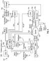
- FIG. 1is a cross-sectional view of a gas turbine engine including a bowed rotor prevention system
- FIG. 2is a block diagram of a control system according to an embodiment of the disclosure.
- FIG. 3is a block diagram of a core turning motor system according to an embodiment of the disclosure.
- FIG. 4is a block diagram of a bowed rotor prevention system according to an embodiment of the disclosure.
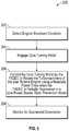
- FIG. 5is a process flow of a method according to embodiments of the disclosure.
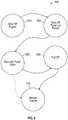
- FIG. 6is a state transition diagram according to embodiments of the disclosure.
- Embodimentsprevent a bowed rotor condition by using a core turning motor to drive rotation of the gas turbine engine under low power conditions.
- Embodimentsuse a full authority digital engine control (FADEC) in a reduced-power mode of operation to drive a core turning motor (CTM) to prevent a bowed rotor condition of the gas turbine engine based on aircraft power.
- the FADECcan internally isolate power requirements in a low-power bowed rotor prevention mode from a full-power (normal) mode used to control operation of the gas turbine engine such that the FADEC need not be fully operational while controlling the CTM.
- a channel of the FADECis operable to monitor the duration of engine core rotation and determine a pass/fail status, for instance, for use upon performing a subsequent engine start process.
- a low powered implementationmay be used that consumes low amounts of power.
- the power used by the FADEC and CTMcombined less than 500 watts of power by the FADEC and the CTM combined while performing core turning (i.e., bowed rotor prevention is active).
- the FADEC and CTMcombine for about 40 watts of power draw while core turning is active.
- Aircraft powercan be selectively provided through an engine interface unit (EIU) as switched power for both the FADEC and the CTM.
- EIUengine interface unit
- the EIU and/or other switch locations, such as the nacelle,can depower the CTM, for instance, to perform maintenance actions.
- the FADECcan drive a discrete output (e.g., a 28 volt output) for bowed rotor prevention at shutdown.
- the FADECmay directly control power to the CTM and/or send a switching request to one or more other systems to enable the CTM.
- the FADECmay remain powered in full-power mode for a predetermined period of time (e.g., 10 minutes) after engine fuel has been cutoff before switching to the low-power bowed rotor prevention mode.
- the FADECcan drive the CTM to rotate an engine core (e.g., starting spool/N2) of the gas turbine engine at about 0.1 revolutions per minute (RPM) with a gear reduction (e.g., greater than 100:1) by applying substantially constant power (i.e., not periodic) for a period of time.
- the CTMmay rotate the starting spool for a partial rotation periodically based on rotation time or reaching a sensed position (e.g., about 180 degrees of rotation per interval).
- the CTMcan include a feedback device, depending on the type of motor selected, to monitor electric current, back electromotive force, torque, and/or other parameters.
- the FADECcan provide a pass/fail (e.g., successful/unsuccessful bowed rotor prevention process) status that is readable by other systems, for instance, a test stand and/or maintenance system, or written to non-volatile memory of the FADEC or other system. If a pass status is observed on the next engine start sequence, the FADEC may continue with normal engine starting operation; otherwise, the FADEC may attempt to use alternate techniques to mitigate a bowed rotor condition, such as dry motoring. Dry motoring can also be used if the engine is started before the CTM is shutdown.
- a pass/faile.g., successful/unsuccessful bowed rotor prevention process
- dry motoringcan be used.
- dry motoringcan be canceled/inhibited during engine starting.
- the FADECcan shut down the CTM based on elapsed motoring time and/or a measured temperature.
- a starter valvecan be actively adjusted to deliver air pressure from an air supply to an engine starting system that controls starting rotor speed. Dry motoring may be performed by running an engine starting system at a lower speed with a longer duration than typically used for engine starting while dynamically adjusting the starter valve to maintain the rotor speed and/or follow a dry motoring profile. Dry motoring is typically performed at a higher speed than bowed rotor prevention performed by the CTM. Some embodiments increase the rotor speed of the starting spool to approach a critical rotor speed gradually and as thermal distortion is decreased the starting spool then accelerates beyond the critical rotor speed to complete the engine starting process.
- the critical rotor speedrefers to a major resonance speed where, if the temperatures are unhomogenized, the combination of a bowed rotor and similarly bowed casing and the resonance would lead to high amplitude oscillation in the rotor and high rubbing of blade tips on one side of the rotor, especially in the high pressure compressor if the rotor is straddle-mounted.
- a bowed rotor prevention system including the CTMcan also include a back-drive preventer (e.g., an overrunning clutch) to isolate the CTM from other sources of driving rotation of the gas turbine engine.
- the CTMcan drive rotation of the gas turbine engine through an accessory gearbox or other gear train as part of a transmission system.
- the CTMis on a starter of the gas turbine engine and drives a starter gear set through a tower shaft to slowly rotate a starting spool of the gas turbine engine.
- the CTMmay be capable of continuous stall torque as well as continuous free running in the case of CTM shaft shear and/or other failure modes.
- a bowed rotor prevention pass/fail statuscan be set to indicate the failure.
- the statuscan be sent to one or more systems, such as an aircraft maintenance computer system.
- the CTMcan rotate turbomachinery of the gas turbine engine at low speeds (e.g. less than 5000 RPM) or at very low speed (e.g., ⁇ 5 revolutions per minute (RPM)) in order to equalize the thermal gradient of the rotating parts after engine shutdown.
- the core turning motorcan interface through any of the gear-driven accessories of the engine, such as an air turbine starter or a crank pad location.
- the power requirements of the core turning motorare substantially reduced in that the rotation needed to equalize the thermal gradients may be on the order of less than 3 RPM.
- the core turning motorcan be controlled to rotate the turbomachinery, e.g., a high pressure spool of the gas turbine engine, for a predetermined period of time (30-40 minutes, for example) or as a function of one or more parametric values such as a measured temperature.
- the turbomachinerye.g., a high pressure spool of the gas turbine engine
- the core turning motorcan be controlled to rotate the turbomachinery, e.g., a high pressure spool of the gas turbine engine, for a predetermined period of time (30-40 minutes, for example) or as a function of one or more parametric values such as a measured temperature.
- Embodimentsavoid high speed rotation (e.g., 5000-7000 RPM) of the engine after shutdown and also avoid requiring a flight crew to monitor the temperature of each engine of a multi-engine aircraft for several minutes prior to restarting each engine.
- a ground cart or other external source to drive engine rotatione.g., an external pneumatic system
- an auxiliary power unit of the aircraftthat is typically used to rotate turbomachinery of the engine at a starting speed
- embodimentsuse an electric motor as the core turning motor operable to slowly rotate (e.g., ⁇ 5 RPM) the turbomachinery after engine shutdown.
- Embodiments of the core turning motorcan be dedicated for use in bowed rotor prevention, and as such, sized with a lower weight and volume than would be needed to drive rotation of the engine at or above an engine starting speed. Gear reductions can be used to reduce electric power consumption.
- gas turbine enginesare rotary-type combustion turbine engines built around a power core made up of a compressor, combustor and turbine, arranged in flow series with an upstream inlet and downstream exhaust.
- the compressorcompresses air from the inlet, which is mixed with fuel in the combustor and ignited to generate hot combustion gas.
- the turbineextracts energy from the expanding combustion gas, and drives the compressor via a common shaft. Energy is delivered in the form of rotational energy in the shaft, reactive thrust from the exhaust, or both.
- Gas turbine enginesprovide efficient, reliable power for a wide range of applications, including aviation and industrial power generation.
- Smaller-scale enginessuch as auxiliary power units typically utilize a one-spool design, with co-rotating compressor and turbine sections.
- Larger-scale jet engines and industrial gas turbinesare generally arranged into a number of coaxially nested spools, which operate at different pressures and temperatures, and rotate at different speeds.
- each spoolis subdivided into a number of stages, which are formed of alternating rows of rotor blade and stator vane airfoils.
- the airfoilsare shaped to turn, accelerate and compress the working fluid flow, or to generate lift for conversion to rotational energy in the turbine.
- turbojet enginesthrust is generated primarily from the exhaust.
- Modern fixed-wing aircraftgenerally employ turbofan and turboprop designs, in which the low pressure spool is coupled to a propulsion fan or propeller.
- Turboshaft enginesare typically used on rotary-wing aircraft, including helicopters.
- Turbofan enginesare commonly divided into high and low bypass configurations.
- High bypass turbofansgenerate thrust primarily from the fan, which drives airflow through a bypass duct oriented around the engine core. This design is common on commercial aircraft and military transports, where noise and fuel efficiency are primary concerns.
- Low bypass turbofansgenerate proportionally more thrust from the exhaust flow, providing greater specific thrust for use on high-performance aircraft, including supersonic jet fighters.
- Unducted (open rotor) turbofans and ducted propeller enginesare also known, in a variety of counter-rotating and aft-mounted configurations.
- FIG. 1a cross-sectional view of a gas turbine engine 10 , in a turbofan configuration is illustrated.
- the illustrated gas turbine engine 10includes a propulsion fan 12 mounted inside a bypass duct 14 upstream of a fan exit guide vane 13 .
- a power core of the engineis formed by a compressor section 16 , a combustor 18 and a turbine section 20 .
- Rotor blades (or airfoils) 21 in the compressor section 16 and/or the turbine section 20may be subject to deflection or bowing if a thermal gradient forms after engine shutdown.
- compressor section 16includes a low pressure compressor 22 and a high pressure compressor 24 .
- the turbine section 20includes high a pressure turbine 26 and a low pressure turbine 28 .
- the low pressure compressor 22is rotationally coupled to the low pressure turbine 28 via a low pressure shaft 30 , thereby forming the low pressure spool or low spool 31 .
- High pressure compressor 24is rotationally coupled to the high pressure turbine 26 via a high pressure shaft 32 , forming the high pressure spool or high spool 33 (also referred to as a starting spool).
- the fan 12accelerates air flow from an inlet 34 through bypass duct 14 , generating thrust.
- the core airflowis compressed in the low pressure compressor 22 and the high pressure compressor 24 and then the compressed airflow is mixed with fuel in the combustor 18 and ignited to generate combustion gas.
- the combustion gasexpands to drive the high and low pressure turbines 26 and 28 , which are rotationally coupled to high pressure compressor 24 and low pressure compressor 22 , respectively. Expanded combustion gases exit through exhaust nozzle 36 , which is shaped to generate additional thrust from the exhaust gas flow.
- the low pressure shaft 30may be coupled to fan 12 via geared drive mechanism 37 , providing improved fan speed control for increased efficiency and reduced engine noise.
- Propulsion fan 12may also function as a first-stage compressor for gas turbine engine 10 , with low pressure compressor 22 performing as an intermediate-stage compressor or booster.
- the low pressure compressor stagesare absent, and air from fan 12 is provided directly to high pressure compressor 24 , or to an independently rotating intermediate compressor spool.
- the gas turbine engine 10may have a range of different shaft and spool geometries, including one-spool, two-spool and three-spool configurations, in both co-rotating and counter-rotating designs.
- Gas turbine engine 10may also be configured as a low bypass turbofan, an open-rotor turbofan, a ducted or un-ducted propeller engine, or an industrial gas turbine.
- Station 2is at an inlet of low pressure compressor 22 having a temperature T 2 .
- Station 3is at an inlet of the combustor 18 having a temperature T 3 .
- Station 4is at an exit of the combustor 18 having a temperature T 4 .
- Station 5is at an exit of the low pressure turbine 28 having a temperature T 5 .
- Temperatures in embodimentsmay be measured and/or modeled at one or more stations 2 - 5 and/or at other locations. Measured and/or modeled temperatures can be normalized to account for hot day/cold day differences. For instance, measured temperature T 2 can be used as an ambient temperature and a modeled or measured temperature (e.g., T 3 ) can be normalized by subtracting measured temperature T 2 .
- an engine accessory gearbox 40is mechanically coupled to a rotating portion of the gas turbine engine 10 , such as the high pressure spool 33 (e.g., an engine core component). Rotation of various engine accessories can be driven through the engine accessory gearbox 40 , such as pumps and electric generators.
- a core turning motor 44is coupled through the engine accessory gearbox 40 as part of a bowed rotor prevention system 42 and may be integrally formed with an engine accessory, such as a starter.
- the bowed rotor prevention system 42also includes FADEC 102 to drive the CTM 44 to prevent a bowed rotor condition of the gas turbine engine 10 based on aircraft power from aircraft power source 60 .
- the FADEC 102can operate in a low-power bowed rotor prevention mode rather than a full-power mode used to control operation of the gas turbine engine 10 .
- the FADEC 102can receive power from other sources, such as one or more generators (e.g., generator 170 of FIG. 4 ).
- a switch 56is interposed between the FADEC 102 and the aircraft power source 60 . Switched power can be provided on a power bus 48 to the FADEC 102 , where the FADEC 102 may regulate and/or condition power provided on power bus 50 to the CTM 44 .
- the FADEC 102can provide commands and retrieve status from the CTM 44 via motor interface 52 .
- a pass/fail statuscan be output from the FADEC 102 on a communication interface 54 to indicate whether the FADEC 102 was able to successfully complete a bowed rotor prevention process using the CTM 44 .
- the pass/fail statuscan be retained in non-volatile memory of the FADEC 102 for later use/reporting, e.g., during full-power mode.
- the FADEC 102can set a maintenance flag upon detecting that the CTM 44 did not turn when commanded.
- the FADEC 102determines that the CTM 44 did not turn or the FADEC 102 was otherwise unsuccessful at completing bowed rotor prevention using the CTM 44 , the FADEC 102 can perform a dry motoring process to mitigate potential bowed rotor conditions.
- the core turning motor 44drives rotation the gas turbine engine 10 at less than 10 RPM.
- the FADEC 102is operable to control a flow of electric current from the aircraft power source 60 to the core turning motor 44 .
- the FADEC 102is operable to engage the core turning motor 44 based on an engine shutdown condition of the gas turbine engine 10 of FIG. 1 .
- the FADEC 102may detect an engine shutdown condition of the gas turbine engine 10 of FIG. 1 and enable low-power bowed rotor prevention mode prior to fully depowering of the FADEC 102 .
- the low-power bowed rotor prevention mode of the FADEC 102can be enabled by another source, such as a sensor, an aircraft communication bus, a discrete switch, or the like.
- the FADEC 102may also monitor the aircraft power source 60 and/or back electromotive force of the core turning motor 44 as part of a monitoring process to confirm proper system operation and capability.
- the FADEC 102may include memory to store instructions that are executed by one or more processors.
- the executable instructionsmay be stored or organized in any manner and at any level of abstraction, such as in connection with a controlling and/or monitoring operation of one or more systems of the gas turbine engine 10 of FIG. 1 .
- the processorscan be any type of central processing unit (CPU), including a general purpose processor, a digital signal processor, a microcontroller, an application specific integrated circuit (ASIC), a field programmable gate array, or the like.
- the memorymay include random access memory (RAM), read only memory (ROM), or other electronic, optical, magnetic, or any other computer readable medium onto which is stored data and control algorithms in a non-transitory form.
- the FADEC 102can include multiple processing systems as separate channels, where only a single channel of the FADEC may be used in the low-power bowed rotor prevention mode.
- a FADEC 102includes channel A 72 A and channel B 72 B, where each of the channels 72 A, 72 B includes a plurality of FADEC resources 74 such as FADEC processing resources 76 , FADEC analog I/O 78 , FADEC discrete I/O 80 , FADEC communications interface 82 , FADEC power supply 84 , and/or other resources (not depicted).
- FADEC resources 74such as FADEC processing resources 76 , FADEC analog I/O 78 , FADEC discrete I/O 80 , FADEC communications interface 82 , FADEC power supply 84 , and/or other resources (not depicted).
- both channels 72 A, 72 Bcan be operational in an active or standby mode.
- low-power bowed rotor prevention modeonly one of the channels 72 A, 72 B may be powered. For instance, if channel A 72 A was active and in control at engine shutdown, channel B 72 B may switch from a standby operational mode to a depowered mode. Further, the low-power bowed rotor prevention mode can depower or reduce power to selected components of the channel 72 A, 72 B that remains powered.
- portions of the FADEC processing resources 76 , FADEC analog I/O 78 , FADEC discrete I/O 80 , FADEC communications interface 82 , FADEC power supply 84 , and/or other resourcescan be depowered or operate in a low-power state in channel A 72 A, while channel B 72 B is fully depowered. Power reduction can be achieved by depowering processing subsystems, output drivers, communication subsystems, and power subsystems that are not used during operation of the CTM 44 of FIG. 1 .
- FIG. 3depicts a core turning motor system 90 as including the CTM 44 , a transmission system 92 , and the high spool (engine starting spool) 33 .
- the transmission system 92can include a gear train 53 and a back-drive preventer 176 (e.g., a one-way clutch).
- the gear train 53can be distributed through a number of shafts (e.g., a tower shaft), gear sets, gear boxes (e.g., an accessory gear box), and/or other transmission components.
- the starting system 100is also referred to generally as a gas turbine engine system.
- the starting system 100includes FADEC 102 with channel A 72 A and channel B 72 B.
- the starting system 100can also include a data storage unit (DSU) 104 that retains data between shutdowns of the gas turbine engine 10 of FIG. 1 .
- the DSU 104includes non-volatile memory and retains data between cycling of power to the FADEC 102 and DSU 104 .
- a communication link 106can include an aircraft and/or test stand communication bus to interface with aircraft controls, e.g., a cockpit, various onboard computer systems, and/or a test stand.
- a dry motoring system 108is operable to drive rotation of a starting spool (e.g., high spool 33 ) of the gas turbine engine 10 of FIG. 1 .
- Either or both channels 72 A, 72 B of FADEC 102can alternate on and off commands to an electromechanical device 110 which may be coupled to a starter valve 116 to achieve a partially open position of the starter valve 116 to control a flow from a starter air supply 114 (also referred to as air supply 114 ) through a transfer duct 118 to an air turbine starter 120 (also referred to as starter 120 or pneumatic starter motor 120 ) to drive rotation of a starting spool of the gas turbine engine 10 below an engine idle speed.
- the air supply 114(also referred to as starter air supply 114 ) can be provided by any known source of compressed air, such as an auxiliary power unit or ground cart.
- the FADEC 102can monitor a speed sensor, such as speed pickup 122 that may sense the speed of the engine rotor through its connection to gearbox 40 which is in turn connected to the high spool 33 via tower shaft 55 through gear train 53 (e.g., rotational speed of high spool 33 ) or any other such sensor for detecting or determining the speed of the gas turbine engine 10 of FIG. 1 .
- the starter 120may be coupled to the gearbox 40 of the gas turbine engine 10 of FIG. 1 directly or through a transmission such as a clutch system.
- the FADEC 102can establish a control loop with respect to rotor speed to adjust positioning of the starter valve 116 .
- the starter valve 116may be designed as an on/off valve which is typically commanded to either fully opened or fully closed. However, there is a time lag to achieve the fully open position and the fully closed position. By selectively alternating an on-command time with an off-command time through the electromechanical device 110 , intermediate positioning states (i.e., partially opened/closed) can be achieved.
- the FADEC 102can modulate the on and off commands (e.g., as a duty cycle using pulse width modulation) to the electromechanical device 110 to further open the starter valve 116 and increase a rotational speed of the starting spool of the gas turbine engine 10 of FIG. 1 .
- the electromechanical device 110has a cycle time defined between an off-command to an on-command to the off-command that is at most half of a movement time for the starter valve 116 to transition from fully closed to fully open.
- Pneumatic lines or a mechanical linkagee.g., via valve control 140
- the electromechanical device 110can be a solenoid that positions the starter valve 116 based on intermittently supplied electric power as commanded by the FADEC 102 .
- the electromechanical device 110is an electric valve controlling muscle air to adjust the position of the starter valve 116 as commanded by the FADEC 102 .
- the dry motoring system 108can use a variable position starter valve as the starter valve 116 .
- Either or both channels of FADEC 102can output a valve control signal 140 operable to dynamically adjust a valve angle of the starter valve 116 that selectively allows a portion of the air supply 114 to pass through the starter valve 116 and transfer duct 118 to air turbine starter 120 .
- the starter valve 116can be a continuous/infinitely adjustable valve that can hold a commanded valve angle, which may be expressed in terms of a percentage open/closed and/or an angular value (e.g., degrees or radians).
- Performance parameters of the starter valve 116can be selected to meet dynamic response requirements of the starting system 100 .
- the starter valve 116has a response rate of 0% to 100% open in less than 40 seconds.
- the starter valve 116has a response rate of 0% to 100% open in less than 30 seconds.
- the starter valve 116has a response rate of 0% to 100% open in less than 20 seconds.
- the FADEC 102can monitor a valve angle of the starter valve 116 using valve angle feedback signals 142 provided to both channels 72 A, 72 B of FADEC 102 .
- both channels 72 A, 72 B of the FADEC 102can use the valve angle feedback signals 142 to track a current valve angle, while only one channel 72 A or 72 B designated as an active channel outputs valve control signal 140 .
- the standby channel of FADEC 102can take over as the active channel to output valve control signal 140 .
- both channels 72 A, 72 B of FADEC 102output all or a portion of a valve angle command simultaneously on the valve control signals 140 .
- the FADEC 102can establish an outer control loop with respect to rotor speed and an inner control loop with respect to the valve angle of the starter valve 116 .
- dry motoringcan be performed according to one or more processes as described in U.S. patent application Ser. No. 15/042,794, which is incorporated by reference herein in its entirety.
- One or more temperature sensors 134can provide measured temperatures at associated locations of the gas turbine engine 10 to the FADEC 102 .
- the temperature sensors 134can be located at station 2 (T 2 ), station 3 (T 3 ), station 4 (T 4 ), station 5 (T 5 ) and/or other locations as previously described with respect to FIG. 1 .
- the starting system 100also includes a core-turning motoring system 150 (also referred to as an auxiliary drive system) that includes CTM 44 that is operable to drive rotation of the starting spool (e.g., high spool 33 ) of the gas turbine engine 10 of FIG. 1 through gearbox 40 .
- a transmission 154(which can be part of transmission system 92 of FIG. 3 ) may be interposed between the CTM 44 and the gearbox 40 for reduction gearing and/or a clutch (e.g., inclusion of the back-drive preventer 176 of FIG. 3 ).
- the transmission 154can interface with the gearbox 40 at a manual crank pad 125 location.
- the core-turning motoring system 150also includes a switch 156 that may be commanded by either or both channels 72 A, 72 B of the FADEC 102 (e.g., using enable 158 ) to provide electrical power for the CTM 44 in a low-power bowed rotor prevention mode.
- the switch 156may be a mechanical switch, electrical relay, or other mechanism for controlling the distribution of electrical power to the core-turning motoring system 150 .
- the switch 156may be an embodiment of switch 56 of FIG. 1 or an additional switch.
- Electrical powermay be provided from an energy storage source 160 and/or an auxiliary energy source 162 , such as ground power or other aircraft/external source, as embodiments of the aircraft power source 60 of FIG. 1 .
- the energy storage source 160can be a battery or capacitor of an aircraft electrical system, which may be charged by a generator 170 through a charger 172 .
- the generator 170may be driven by the gearbox 40 (e.g., during operation of the gas turbine engine 10 ) or other source of rotational energy on the aircraft. Examples of the generator 170 include a permanent magnet alternator/generator, an integrated drive generator, a variable frequency generator, and other generator technologies known in the art.
- the core-turning motoring system 150 or the dry motoring system 108can be used to prevent/mitigate a bowed rotor condition depending on the present operating characteristics of the gas turbine engine 10 of FIG. 1 .
- the FADEC 102 in combination with the dry motoring system 108 and the core-turning motoring system 150may be collectively referred to as a bowed rotor prevention system 101 that is operable to prevent and/or mitigate a bowed rotor condition of the gas turbine engine 10 of FIG. 1 .
- the FADEC 102is operable to engage the CTM 44 and drive rotation of the engine core of the gas turbine engine 10 of FIG. 1 .
- the FADEC 102may drive rotation of the CTM 44 until a time or temperature threshold is met or a shutoff request is detected based on one or more of: a detected opening of a nacelle of the gas turbine engine 10 , a shutoff switch accessible to maintenance personnel on the nacelle or the gas turbine engine 10 , a computer interface command on the aircraft, a detected fault condition, a time limit, a temperature limit, or a start command of the gas turbine engine 10 of FIG. 1 .
- Rotationcan be continuous or periodic based on time and/or sensed position.
- FIG. 5is a process flow of a method 200 according to an embodiment.
- the method 200can be implemented by the bowed rotor prevention system 42 of FIG. 1 and/or bowed rotor prevention system 101 of FIG. 4 , and thus FIG. 5 is described with reference to FIGS. 1-5 .
- an engine shutdown condition of the gas turbine engine 10is detected, for instance, by the FADEC 102 while controlling operation of the gas turbine engine 10 in a full-power mode. After a confirmation period of time elapses, the FADEC 102 can initiate bowed rotor prevention and transition from full-power mode to low-power bowed rotor prevention mode.
- the FADEC 102engages the core turning motor 44 with turbomachinery of the gas turbine engine 10 , for instance, through the engine accessory gearbox 40 by enabling a flow of electric current on the power bus 50 as provided by the aircraft power source 60 .
- the FADEC 102controls the core turning motor 44 to rotate the turbomachinery of the gas turbine engine 10 using a reduced power draw from aircraft power when the FADEC 102 is partially depowered in the low-power bowed rotor prevention mode.
- the core turning motor 44rotates turbomachinery of the gas turbine engine 10 at a low speed (e.g., ⁇ 5 RPM) until a bowed rotor prevention threshold condition is met (e.g., a targeted time and/or temperature condition is met). Rotation may be substantially constant at about 0.1 RPM.
- the FADEC 102can control the core turning motor 44 to drive rotation of the engine core for a partial rotation based on a timed duration or a sensed position, for instance, by periodically performing a half revolution of the engine core.
- the FADEC 102monitors for successful completion of the bowed rotor prevention process and makes the results available to one or more systems, e.g., an aircraft maintenance computer. If needed, the FADEC 102 can perform a dry motoring process on start-up when the FADEC 102 determines that the bowed rotor prevention process was not successful.
- the FADEC 102can determine a bowed rotor risk parameter based on engine thermal history and/or a temperature measurement, such as T 3 .
- the FADEC 102can use the bowed rotor risk parameter to determine whether to enable the core turning motor 44 and one or more shutdown limits of the core turning motor 44 , such as a time limit or temperature limit. For instance, the FADEC 102 can depower itself and the core turning motor 44 based on expiration of the time limit or as a function of a measured temperature, such as T 3 .
- the core turning motor 44can be shut down based on one or more of: a detected opening of a nacelle of the gas turbine engine 10 , a shutoff switch accessible to maintenance personnel on the nacelle or the gas turbine engine 10 , a computer interface command on the aircraft, a detected fault condition, a time limit, a temperature limit, or a start command of the gas turbine engine 10 .
- FIG. 6is a state transition diagram 300 further illustrating the transitions from engine shutoff to restart as described with respect to FIGS. 1-4 .
- the FADEC 102detects an engine shutdown condition of gas turbine engine 10 while the FADEC 102 is operating in full-power mode.
- the FADEC 102transitions to state 304 and performs various system checks during a shutdown transition period. For example, if channel A 72 A is in control, channel A 72 A may verify that connections and system components associated with operating the CTM 44 are functional. If there is an issue detected that would prevent channel A 72 A from controlling CTM 44 , channel B 72 B (e.g., presently in standby mode) may take control if channel B 72 B is able to control the CTM 44 .
- the FADEC 102may continue to operate in full-power mode until shutdown tasks, such as message reporting, data recording, and the like, have completed.
- the FADEC 102can transition from state 304 to state 306 for reduced power operation in a low-power bowed rotor prevention mode.
- state 306channel 72 A or 72 B can be depowered, and the opposite channel 72 B or 72 A can remain powered as a controller of CTM 44 .
- a subset of FADEC processing resources 74such as solenoid drives and/or a protection processor can be depowered or operated in a low-power state to reduce power draw by the FADEC 102 .
- the FADEC 102controls the CTM 44 to continuously or periodically rotate the engine core of the gas turbine engine 10 until a shutdown condition is met or an engine restart request is received. If a shutdown condition is met (e.g., bowed rotor risk is sufficiently reduced), the FADEC 102 can transition to state 308 and depower itself and the CTM 44 . When an engine restart is requested, the FADEC 102 transitions to state 310 and determines whether dry motoring is needed before completing the starting process of the gas turbine engine 10 .
- a shutdown conditione.g., bowed rotor risk is sufficiently reduced
- Technical effects and benefitsinclude using a core turning motor to slowly rotate turbomachinery of a gas turbine engine after shutdown to equalize a thermal gradient of rotating parts that were heated during operation.
- Using a reduced power operating mode of a multi-channel FADEC and a lower power electric motor with gear reductionprovides reduced power consumption during bowed rotor prevention processes.
Landscapes
- Engineering & Computer Science (AREA)
- Mechanical Engineering (AREA)
- General Engineering & Computer Science (AREA)
- Chemical & Material Sciences (AREA)
- Combustion & Propulsion (AREA)
- Control Of Turbines (AREA)
- Control Of Eletrric Generators (AREA)
Abstract
Description
Claims (20)
Priority Applications (1)
| Application Number | Priority Date | Filing Date | Title |
|---|---|---|---|
| US15/186,839US10787933B2 (en) | 2016-06-20 | 2016-06-20 | Low-power bowed rotor prevention and monitoring system |
Applications Claiming Priority (1)
| Application Number | Priority Date | Filing Date | Title |
|---|---|---|---|
| US15/186,839US10787933B2 (en) | 2016-06-20 | 2016-06-20 | Low-power bowed rotor prevention and monitoring system |
Publications (2)
| Publication Number | Publication Date |
|---|---|
| US20170363012A1 US20170363012A1 (en) | 2017-12-21 |
| US10787933B2true US10787933B2 (en) | 2020-09-29 |
Family
ID=60659297
Family Applications (1)
| Application Number | Title | Priority Date | Filing Date |
|---|---|---|---|
| US15/186,839Active2038-06-24US10787933B2 (en) | 2016-06-20 | 2016-06-20 | Low-power bowed rotor prevention and monitoring system |
Country Status (1)
| Country | Link |
|---|---|
| US (1) | US10787933B2 (en) |
Cited By (7)
| Publication number | Priority date | Publication date | Assignee | Title |
|---|---|---|---|---|
| US20220098997A1 (en)* | 2019-01-29 | 2022-03-31 | Safran Aircraft Engines | Method for controlling the bending deformation of a turbomachine shaft at rest subjected to the residual heat of operation of the turbomachine |
| US20220298971A1 (en)* | 2021-03-17 | 2022-09-22 | Airbus Operation (S.A.S) | Method for protecting an aircraft engine on spin-up |
| US11682535B2 (en) | 2021-03-12 | 2023-06-20 | Essex Industries, Inc. | Rocker switch |
| US11688568B2 (en) | 2021-03-15 | 2023-06-27 | Essex Industries, Inc. | Five-position switch |
| US11702952B2 (en) | 2021-11-11 | 2023-07-18 | General Electric Company | Thermal bias control in turbomachines |
| US12298197B2 (en) | 2023-01-09 | 2025-05-13 | General Electric Company | System and method for reducing motoring time in a turbomachine based on shaft deflection |
| US12366208B2 (en) | 2023-07-28 | 2025-07-22 | Unison Industries, Llc | Turbine engine including an engine starter assembly |
Families Citing this family (13)
| Publication number | Priority date | Publication date | Assignee | Title |
|---|---|---|---|---|
| US10598047B2 (en) | 2016-02-29 | 2020-03-24 | United Technologies Corporation | Low-power bowed rotor prevention system |
| US20180030900A1 (en)* | 2016-08-01 | 2018-02-01 | Honeywell International Inc. | Air Turbine Starter with Integrated Motor for Main Engine Cooling |
| US10781754B2 (en) | 2017-12-08 | 2020-09-22 | Pratt & Whitney Canada Corp. | System and method for rotor bow mitigation |
| US10823014B2 (en)* | 2017-12-13 | 2020-11-03 | General Electric Company | Turbine engine for reducing rotor bow and method thereof |
| GB2571992A (en)* | 2018-03-16 | 2019-09-18 | Rolls Royce Plc | Gas turbine engine and method of maintaining a gas turbine engine |
| US11261795B2 (en) | 2018-10-18 | 2022-03-01 | Rolls-Royce North American Technologies, Inc. | Dual mode starter generator |
| US11008944B2 (en) | 2018-10-18 | 2021-05-18 | Rolls-Royce North American Technologies, Inc. | Coaxial starter/generator and air turbine starter |
| US11002238B2 (en)* | 2019-02-13 | 2021-05-11 | Pratt & Whitney Canada Corp. | Method and system for starting an engine |
| US11486310B2 (en) | 2020-03-27 | 2022-11-01 | Pratt & Whitney Canada Corp. | System and method for dynamic engine motoring |
| US11668248B2 (en) | 2020-03-27 | 2023-06-06 | Pratt & Whitney Canada Corp. | Start-up system and method for rotor bow mitigation |
| CN113738458B (en)* | 2020-05-29 | 2023-09-29 | 中国航发商用航空发动机有限责任公司 | Gas turbine, rotor heat bending prevention device and driving device thereof |
| US11525370B2 (en) | 2020-11-13 | 2022-12-13 | General Electric Company | Method and system for mitigating rotor bow in a turbo machine |
| US12018578B1 (en)* | 2023-04-12 | 2024-06-25 | Rtx Corporation | Core turning system |
Citations (129)
| Publication number | Priority date | Publication date | Assignee | Title |
|---|---|---|---|---|
| US1951875A (en) | 1932-08-06 | 1934-03-20 | Cutler Hammer Inc | Power transmission mechanism |
| US2617253A (en) | 1950-09-23 | 1952-11-11 | Gen Electric | Safety control system for cooling a gas turbine power plant on shutdown |
| US2962597A (en) | 1959-06-09 | 1960-11-29 | Westinghouse Electric Corp | Power plant apparatus |
| US3057155A (en) | 1959-05-15 | 1962-10-09 | English Electric Co Ltd | Starting control arrangements of gas turbines |
| US3151452A (en) | 1962-10-22 | 1964-10-06 | Bendix Corp | Electro-mechanical control for air breathing starter |
| US3764815A (en) | 1971-03-06 | 1973-10-09 | Siemens Ag | Start-up converter |
| US3793905A (en) | 1972-08-14 | 1974-02-26 | Twin Disc Inc | Gas turbine starting and auxiliary turning mechanism |
| GB1374810A (en) | 1970-10-20 | 1974-11-20 | Westinghouse Electric Corp | Gas turbine electric power plant |
| US3898439A (en)* | 1970-10-20 | 1975-08-05 | Westinghouse Electric Corp | System for operating industrial gas turbine apparatus and gas turbine electric power plants preferably with a digital computer control system |
| US3924141A (en)* | 1973-06-20 | 1975-12-02 | Westinghouse Electric Corp | Gas turbine power plant control apparatus including a two-shot shutdown system |
| US3951008A (en)* | 1975-01-08 | 1976-04-20 | Twin Disc, Incorporated | Power transmitting mechanism for starting a high inertia load and having retarder means for auxiliary starting motor |
| US4019315A (en)* | 1973-06-20 | 1977-04-26 | Westinghouse Electric Corporation | Gas turbine power plant control apparatus including a temperature reset starting control system and an ignition pressure control system |
| US4044550A (en) | 1975-09-10 | 1977-08-30 | The Boeing Company | Turbine wheel containment shroud for a pneumatically powered turbine engine starter motor |
| US4069424A (en) | 1976-05-10 | 1978-01-17 | Turbodyne Corporation (Gas Turbine Div.) | Shaft turning parking bus for multiple unit installations utilizing a single motorized generator control system |
| US4144421A (en) | 1975-12-19 | 1979-03-13 | Hitachi, Ltd. | Hydraulic machine shutdown sensor assembly |
| US4380146A (en)* | 1977-01-12 | 1983-04-19 | Westinghouse Electric Corp. | System and method for accelerating and sequencing industrial gas turbine apparatus and gas turbine electric power plants preferably with a digital computer control system |
| GB2117842A (en) | 1982-03-25 | 1983-10-19 | Rolls Royce | Means for equalising the temperatures within a gas turbine engine |
| US4598551A (en) | 1985-10-25 | 1986-07-08 | General Electric Company | Apparatus and method for controlling steam turbine operating conditions during starting and loading |
| US4608820A (en)* | 1985-05-03 | 1986-09-02 | Chandler Evans Inc. | Dual stepper motor actuator for fuel metering valve |
| US4627234A (en) | 1983-06-15 | 1986-12-09 | Sundstrand Corporation | Gas turbine engine/load compressor power plants |
| US4713985A (en) | 1984-05-31 | 1987-12-22 | Kabushiki Kaisya Advance Kaihatsu Kenkyujo | Transmission apparatus |
| US4718229A (en)* | 1985-10-30 | 1988-01-12 | Rolls-Royce Plc | Failsafe electronic control systems |
| US4722061A (en)* | 1984-12-20 | 1988-01-26 | United Technologies Corporation | Establishing synthesis validity between two signal sources |
| US4733529A (en) | 1986-09-26 | 1988-03-29 | Cef Industries, Inc. | Performance envelope extension device for a gas turbine engine |
| US4854120A (en) | 1986-09-26 | 1989-08-08 | Cef Industries, Inc. | Performance envelope extension method for a gas turbine engine |
| US4979362A (en) | 1989-05-17 | 1990-12-25 | Sundstrand Corporation | Aircraft engine starting and emergency power generating system |
| US5103629A (en) | 1989-11-20 | 1992-04-14 | Westinghouse Electric Corp. | Gas turbine control system having optimized ignition air flow control |
| US5123239A (en) | 1991-02-14 | 1992-06-23 | Sundstrand Corporation | Method of starting a gas turbine engine |
| US5127220A (en) | 1991-02-28 | 1992-07-07 | Allied-Signal Inc. | Method for accelerating a gas turbine engine |
| US5174109A (en) | 1990-10-25 | 1992-12-29 | Sundstrand Corporation | Clutch to disconnect loads during turbine start-up |
| US5184458A (en) | 1989-11-21 | 1993-02-09 | Lampe Steven W | Power unit fuel pressurization system |
| US5201798A (en) | 1990-09-24 | 1993-04-13 | Allied-Signal Inc. | Multifunction integrated power unit and power transfer apparatus therefor |
| US5349814A (en) | 1993-02-03 | 1994-09-27 | General Electric Company | Air-start assembly and method |
| WO1999000585A1 (en) | 1997-06-27 | 1999-01-07 | MTU MOTOREN- UND TURBINEN-UNION MüNCHEN GMBH | Device for the emergency stop of a gas turbine |
| US6098011A (en)* | 1998-05-18 | 2000-08-01 | Alliedsignal, Inc. | Efficient fuzzy logic fault accommodation algorithm |
| US6146090A (en)* | 1998-12-22 | 2000-11-14 | General Electric Co. | Cooling/heating augmentation during turbine startup/shutdown using a seal positioned by thermal response of turbine parts and consequent relative movement thereof |
| US6168377B1 (en) | 1999-01-27 | 2001-01-02 | General Electric Co. | Method and apparatus for eliminating thermal bowing of steam turbine rotors |
| US6176074B1 (en)* | 1998-06-05 | 2001-01-23 | Pratt & Whitney Canada Corp. | Shaft decouple logic for gas turbine |
| US6190127B1 (en) | 1998-12-22 | 2001-02-20 | General Electric Co. | Tuning thermal mismatch between turbine rotor parts with a thermal medium |
| US6318958B1 (en) | 1998-08-21 | 2001-11-20 | Alliedsignal, Inc. | Air turbine starter with seal assembly |
| US6353790B1 (en)* | 1999-10-05 | 2002-03-05 | Honda Giken Kogyo Kabushiki Kaisha | Gas turbine aeroengine control system |
| US6439504B1 (en) | 2001-06-15 | 2002-08-27 | Honeywell International, Inc. | System and method for sustaining electric power during a momentary power interruption in an electric thrust reverser actuation system |
| US6478534B2 (en) | 1998-08-18 | 2002-11-12 | Siemnes Aktiengesellschaft | Turbine casing |
| US6498978B2 (en) | 2001-05-18 | 2002-12-24 | General Electric Company | System and method for monitoring thermal state to normalize engine trending data |
| JP2002371806A (en) | 2001-06-18 | 2002-12-26 | Mitsubishi Heavy Ind Ltd | Turbine device |
| US6517314B1 (en) | 2001-11-05 | 2003-02-11 | General Electric Company | Method and apparatus for eliminating thermal bowing and axial thrust loads of steam turbine rotors |
| US20030056492A1 (en)* | 2001-09-24 | 2003-03-27 | Henson Nigel Herbert | Electronic engine controller |
| US20030056494A1 (en)* | 2001-09-24 | 2003-03-27 | David Coleman | Electronic engine controller |
| US6558118B1 (en) | 2001-11-01 | 2003-05-06 | General Electric Company | Bucket dovetail bridge member and method for eliminating thermal bowing of steam turbine rotors |
| US6681579B2 (en) | 2002-02-07 | 2004-01-27 | Honeywell International, Inc. | Air turbine starter with fluid flow control |
| JP2004036414A (en) | 2002-06-28 | 2004-02-05 | Ebara Corp | Gas turbine device |
| US20040088991A1 (en)* | 2001-11-13 | 2004-05-13 | Steven Gallant | Fault management system for gas turbine engines |
| US20040131138A1 (en) | 2001-05-25 | 2004-07-08 | Michael Correia | Brayton cycle nuclear power plant and a method of starting the brayton cycle |
| US6762512B2 (en) | 2002-05-10 | 2004-07-13 | Siemens Westinghourse Power Corporation | Methods for starting a combustion turbine and combustion turbine generator configured to implement same methods |
| US6943699B2 (en) | 2003-07-23 | 2005-09-13 | Harris Corporation | Wireless engine monitoring system |
| US20050267667A1 (en)* | 2004-05-26 | 2005-12-01 | Honda Motor Co., Ltd. | Control system for gas-turbine engine |
| US20050284214A1 (en)* | 2004-06-21 | 2005-12-29 | Gustafson James R | Electric engine start system with inspection mode |
| US20060188372A1 (en)* | 2005-02-22 | 2006-08-24 | General Electric Company | Turning gear drive system |
| US7104072B2 (en) | 2004-08-16 | 2006-09-12 | Hamilton Sundstrand Corporation | Combined power main engine start system |
| US7133801B2 (en) | 2002-06-07 | 2006-11-07 | Exxon Mobil Research And Engineering Company | System and methodology for vibration analysis and condition monitoring |
| US7409319B2 (en) | 2003-11-24 | 2008-08-05 | General Electric Company | Method and apparatus for detecting rub in a turbomachine |
| US20080211237A1 (en) | 2006-11-23 | 2008-09-04 | Hispano Suiza | Electrical power supply for an aircraft |
| US7428819B2 (en) | 2004-06-22 | 2008-09-30 | Alstom Technology Ltd. | Method for the operation of a compressor of a gas turbine with evaporative cooling of the compressor induction air |
| US20090071442A1 (en)* | 2007-09-19 | 2009-03-19 | Honeywell International, Inc. | Direct metering fuel system with an integral redundant motor pump |
| US7507070B2 (en) | 1999-03-27 | 2009-03-24 | Rolls-Royce Plc | Gas turbine engine and a rotor for a gas turbine engine |
| US7543439B2 (en) | 2004-07-22 | 2009-06-09 | Rolls-Royce Plc | Generator assembly |
| US7587133B2 (en) | 2003-09-03 | 2009-09-08 | Siemens Aktiengesellschaft | Method for starting a continuous steam generator and continuous steam generator for carrying out said method |
| US20090301053A1 (en) | 2006-06-10 | 2009-12-10 | Mtu Aero Engines Gmbh | Gas Turbine and Method of Operating a Gas Turbine |
| FR2933131A1 (en) | 2008-06-25 | 2010-01-01 | Snecma | Ring fixing support for bypass turbojet engine in airplane, has control system individually controlling heating circuits and homogenizing thermal deformation of support in case of stopping of gas turbine at hot restarting of engine |
| US20100095791A1 (en) | 2008-10-20 | 2010-04-22 | Mactaggart Scott (Holdings) Limited | Apparatus and method for rotating a shaft |
| US20100132365A1 (en) | 2004-04-20 | 2010-06-03 | Gustavo Francisco Labala | Start-Up Control For a Compact Lightweight Turbine |
| US7742881B2 (en) | 2007-08-02 | 2010-06-22 | General Electric Company | System and method for detection of rotor eccentricity baseline shift |
| US20100293961A1 (en) | 2009-05-19 | 2010-11-25 | Hamilton Sundstrand Corporation | Gas turbine starting with stepping speed control |
| US20110046863A1 (en)* | 2009-08-24 | 2011-02-24 | Honda Motor Co., Ltd. | Control apparatus for aeroplane gas turbine engine |
| US7909566B1 (en) | 2006-04-20 | 2011-03-22 | Florida Turbine Technologies, Inc. | Rotor thrust balance activated tip clearance control system |
| US20110077783A1 (en) | 2008-11-03 | 2011-03-31 | United Technologies Corporation | System and method for design and control of engineering systems utilizing component-level dynamic mathematical model |
| EP2305986A2 (en) | 2009-10-05 | 2011-04-06 | General Electric Company | Methods and systems for mitigating distortion of gas turbine shaft |
| US20110138816A1 (en)* | 2008-11-12 | 2011-06-16 | Kazuhiro Takeda | Driving device and an operation method of a compressor |
| US20110146276A1 (en) | 2009-12-23 | 2011-06-23 | General Electric Company | Method of starting a steam turbine |
| US20110153295A1 (en) | 2009-12-21 | 2011-06-23 | United Technologies Corporation | Method and system for modeling the performance of a gas turbine engine |
| US7972105B2 (en) | 2007-05-10 | 2011-07-05 | General Electric Company | Turbine anti-rotating stall schedule |
| US20110296843A1 (en) | 2010-06-04 | 2011-12-08 | Lawson Jr T Towles | Positive displacement power extraction compensation device |
| US20120240591A1 (en) | 2007-12-10 | 2012-09-27 | General Electric Company | Method for shutting down a generator to prepare the generator for restart |
| US8291715B2 (en) | 2008-06-11 | 2012-10-23 | Honeywell International Inc. | Bi-modal turbine assembly and starter / drive turbine system employing the same |
| US20120266601A1 (en) | 2011-04-22 | 2012-10-25 | General Electric Company | System and method for removing heat from a turbomachine |
| US8306776B2 (en) | 2008-06-30 | 2012-11-06 | Mitsubishi Heavy Industries, Ltd. | Method and system for calculating misalignment of rotational body |
| US20120316748A1 (en)* | 2011-06-09 | 2012-12-13 | Airbus (Sas) | Method And Device For Monitoring A Turbine Engine Of An Aircraft |
| WO2013007912A1 (en) | 2011-07-12 | 2013-01-17 | Turbomeca | Method for starting a turbomachine that reduces the thermal imbalance |
| US20130031912A1 (en) | 2011-08-01 | 2013-02-07 | Hamilton Sundstrand Corporation | Gas turbine start architecture |
| US20130091850A1 (en) | 2011-10-13 | 2013-04-18 | Hamilton Sundstrand Corporation | Method and system for reducing hot soakback |
| US20130101391A1 (en) | 2011-09-19 | 2013-04-25 | Alstom Technology Ltd. | Self-Adjusting Device for Controlling the Clearance Between Rotating and Stationary Components of a Thermally Loaded Turbo Machine |
| US20130251501A1 (en) | 2012-03-26 | 2013-09-26 | Mitsubishi Heavy Industries, Ltd. | Method and purge apparatus for preventing deformation of chamber of gas turbine, and gas turbine providing purge apparatus |
| US20130255220A1 (en)* | 2012-03-30 | 2013-10-03 | General Electric Company | Distributed gas turbine engine control system |
| US8770913B1 (en) | 2010-06-17 | 2014-07-08 | Florida Turbine Technologies, Inc. | Apparatus and process for rotor creep monitoring |
| US8776530B2 (en) | 2011-11-23 | 2014-07-15 | General Electric Company | Gas turbine engine lockout reduction |
| US20140199157A1 (en) | 2013-01-16 | 2014-07-17 | Alstom Technology Ltd | Method for barring a rotor of a turbomachine and barring apparatus for conducting such method |
| US20140241878A1 (en) | 2013-02-28 | 2014-08-28 | General Electric Company | System and method for controlling a wind turbine based on identified surface conditions of the rotor blades |
| US20140271152A1 (en) | 2013-03-13 | 2014-09-18 | Jose L. Rodriguez | Turbine engine temperature control system with heating element for a gas turbine engine |
| US20140260306A1 (en)* | 2013-03-14 | 2014-09-18 | Pratt & Whitney Canada Corp. | Engine starting system using stored energy |
| WO2014152701A1 (en) | 2013-03-15 | 2014-09-25 | United Technologies Corporation | Compact aero-thermo model based control system |
| US20140301820A1 (en) | 2013-04-03 | 2014-10-09 | Uwe Lohse | Turbine engine shutdown temperature control system with nozzle injection for a gas turbine engine |
| US20140318144A1 (en) | 2011-11-14 | 2014-10-30 | Nuovo Pignone S.P.A. | Device and method for slow turning of an aeroderivative gas turbine |
| US20140334927A1 (en) | 2011-11-21 | 2014-11-13 | Vestas Wind Systems A/S | Shutdown controller for a wind turbine and a method of shutting down a wind turbine |
| US20140366546A1 (en) | 2013-06-13 | 2014-12-18 | Solar Turbines Incorporated | Variable frequency drive power ride thru |
| US20140373518A1 (en) | 2013-06-19 | 2014-12-25 | Airbus Operations (Sas) | System and method for spinning up a rotary element of a mechanical device, particularly a turbomachine |
| US20140373554A1 (en) | 2013-06-21 | 2014-12-25 | United Technologies Corporation | Air turbine starter pressure monitor system |
| US20140373552A1 (en) | 2013-06-25 | 2014-12-25 | Airbus Operations (Sas) | Method and system for starting up an aircraft turbomachine by real-time regulation of air flow |
| US20140373553A1 (en) | 2013-06-25 | 2014-12-25 | Airbus Operations (Sas) | Method and system for starting up an aircraft turbomachine |
| US20150016949A1 (en) | 2013-07-09 | 2015-01-15 | Rolls-Royce Plc | Tip clearance control method |
| WO2015030946A1 (en) | 2013-08-26 | 2015-03-05 | United Technologies Corporation | Gas turbine engine with fan clearance control |
| US8979705B2 (en) | 2009-07-17 | 2015-03-17 | Snecma | Method and system for controlling aircraft engine starter/generator |
| US20150115608A1 (en) | 2013-10-31 | 2015-04-30 | General Electric Company | System and method for controlling a wind turbine |
| US20150121874A1 (en) | 2013-11-07 | 2015-05-07 | Mitsubishi Hitachi Power Systems, Ltd. | Activation control device |
| US20150128592A1 (en) | 2012-04-27 | 2015-05-14 | Turbomeca | Method and system for the emergency start-up of an energy generator set |
| US20150159625A1 (en) | 2013-12-11 | 2015-06-11 | General Electric Company | System and method for controlling a wind turbine system |
| US9086018B2 (en) | 2010-04-23 | 2015-07-21 | Hamilton Sundstrand Corporation | Starting a gas turbine engine to maintain a dwelling speed after light-off |
| WO2016069303A1 (en)* | 2014-10-29 | 2016-05-06 | Unison Industries, Llc | Method and system for operating a rotatable machine |
| US9394084B1 (en) | 2013-04-11 | 2016-07-19 | Rolls-Royce Plc | Aircraft electrical system operating method |
| US20160265445A1 (en)* | 2015-03-11 | 2016-09-15 | Pratt & Whitney Canada Corp. | Overthrust protection system and method |
| US20160348588A1 (en)* | 2015-01-28 | 2016-12-01 | General Electric Company | Method of starting a gas turbine engine |
| US9664070B1 (en)* | 2016-02-12 | 2017-05-30 | United Technologies Corporation | Bowed rotor prevention system |
| US20170233089A1 (en)* | 2016-02-16 | 2017-08-17 | Airbus Operations Sas | System and method for starting the engines of a twin-engine aircraft |
| US20170234235A1 (en)* | 2016-02-12 | 2017-08-17 | Hamilton Sundstrand Corporation | Electro-pneumatic gas turbine engine motoring system for bowed rotor engine starts |
| EP3211184A1 (en) | 2016-02-29 | 2017-08-30 | United Technologies Corporation | Bowed rotor prevention system and associated method of bowed rotor prevention |
| US20170342855A1 (en)* | 2016-05-24 | 2017-11-30 | General Electric Company | Turbine engine and method of cooling |
| US20170342908A1 (en)* | 2016-05-24 | 2017-11-30 | General Electric Company | Turbine engine and method of operating |
| US20180010522A1 (en)* | 2016-07-05 | 2018-01-11 | Hamilton Sundstrand Corporation | Gas turbine engine starter reduction gear train with stacked planetary gear systems |
| US10174678B2 (en)* | 2016-02-12 | 2019-01-08 | United Technologies Corporation | Bowed rotor start using direct temperature measurement |
| US10443507B2 (en)* | 2016-02-12 | 2019-10-15 | United Technologies Corporation | Gas turbine engine bowed rotor avoidance system |
- 2016
- 2016-06-20USUS15/186,839patent/US10787933B2/enactiveActive
Patent Citations (138)
| Publication number | Priority date | Publication date | Assignee | Title |
|---|---|---|---|---|
| US1951875A (en) | 1932-08-06 | 1934-03-20 | Cutler Hammer Inc | Power transmission mechanism |
| US2617253A (en) | 1950-09-23 | 1952-11-11 | Gen Electric | Safety control system for cooling a gas turbine power plant on shutdown |
| US3057155A (en) | 1959-05-15 | 1962-10-09 | English Electric Co Ltd | Starting control arrangements of gas turbines |
| US2962597A (en) | 1959-06-09 | 1960-11-29 | Westinghouse Electric Corp | Power plant apparatus |
| US3151452A (en) | 1962-10-22 | 1964-10-06 | Bendix Corp | Electro-mechanical control for air breathing starter |
| GB1374810A (en) | 1970-10-20 | 1974-11-20 | Westinghouse Electric Corp | Gas turbine electric power plant |
| US3898439A (en)* | 1970-10-20 | 1975-08-05 | Westinghouse Electric Corp | System for operating industrial gas turbine apparatus and gas turbine electric power plants preferably with a digital computer control system |
| US3764815A (en) | 1971-03-06 | 1973-10-09 | Siemens Ag | Start-up converter |
| US3793905A (en) | 1972-08-14 | 1974-02-26 | Twin Disc Inc | Gas turbine starting and auxiliary turning mechanism |
| US3924141A (en)* | 1973-06-20 | 1975-12-02 | Westinghouse Electric Corp | Gas turbine power plant control apparatus including a two-shot shutdown system |
| US4019315A (en)* | 1973-06-20 | 1977-04-26 | Westinghouse Electric Corporation | Gas turbine power plant control apparatus including a temperature reset starting control system and an ignition pressure control system |
| US3951008A (en)* | 1975-01-08 | 1976-04-20 | Twin Disc, Incorporated | Power transmitting mechanism for starting a high inertia load and having retarder means for auxiliary starting motor |
| US4044550A (en) | 1975-09-10 | 1977-08-30 | The Boeing Company | Turbine wheel containment shroud for a pneumatically powered turbine engine starter motor |
| US4144421A (en) | 1975-12-19 | 1979-03-13 | Hitachi, Ltd. | Hydraulic machine shutdown sensor assembly |
| US4069424A (en) | 1976-05-10 | 1978-01-17 | Turbodyne Corporation (Gas Turbine Div.) | Shaft turning parking bus for multiple unit installations utilizing a single motorized generator control system |
| US4380146A (en)* | 1977-01-12 | 1983-04-19 | Westinghouse Electric Corp. | System and method for accelerating and sequencing industrial gas turbine apparatus and gas turbine electric power plants preferably with a digital computer control system |
| GB2117842A (en) | 1982-03-25 | 1983-10-19 | Rolls Royce | Means for equalising the temperatures within a gas turbine engine |
| US4627234A (en) | 1983-06-15 | 1986-12-09 | Sundstrand Corporation | Gas turbine engine/load compressor power plants |
| US4713985A (en) | 1984-05-31 | 1987-12-22 | Kabushiki Kaisya Advance Kaihatsu Kenkyujo | Transmission apparatus |
| US4722061A (en)* | 1984-12-20 | 1988-01-26 | United Technologies Corporation | Establishing synthesis validity between two signal sources |
| US4608820A (en)* | 1985-05-03 | 1986-09-02 | Chandler Evans Inc. | Dual stepper motor actuator for fuel metering valve |
| US4598551A (en) | 1985-10-25 | 1986-07-08 | General Electric Company | Apparatus and method for controlling steam turbine operating conditions during starting and loading |
| US4718229A (en)* | 1985-10-30 | 1988-01-12 | Rolls-Royce Plc | Failsafe electronic control systems |
| US4733529A (en) | 1986-09-26 | 1988-03-29 | Cef Industries, Inc. | Performance envelope extension device for a gas turbine engine |
| US4854120A (en) | 1986-09-26 | 1989-08-08 | Cef Industries, Inc. | Performance envelope extension method for a gas turbine engine |
| US4979362A (en) | 1989-05-17 | 1990-12-25 | Sundstrand Corporation | Aircraft engine starting and emergency power generating system |
| US5103629A (en) | 1989-11-20 | 1992-04-14 | Westinghouse Electric Corp. | Gas turbine control system having optimized ignition air flow control |
| US5184458A (en) | 1989-11-21 | 1993-02-09 | Lampe Steven W | Power unit fuel pressurization system |
| US5201798A (en) | 1990-09-24 | 1993-04-13 | Allied-Signal Inc. | Multifunction integrated power unit and power transfer apparatus therefor |
| US5174109A (en) | 1990-10-25 | 1992-12-29 | Sundstrand Corporation | Clutch to disconnect loads during turbine start-up |
| US5123239A (en) | 1991-02-14 | 1992-06-23 | Sundstrand Corporation | Method of starting a gas turbine engine |
| US5127220A (en) | 1991-02-28 | 1992-07-07 | Allied-Signal Inc. | Method for accelerating a gas turbine engine |
| US5349814A (en) | 1993-02-03 | 1994-09-27 | General Electric Company | Air-start assembly and method |
| WO1999000585A1 (en) | 1997-06-27 | 1999-01-07 | MTU MOTOREN- UND TURBINEN-UNION MüNCHEN GMBH | Device for the emergency stop of a gas turbine |
| US6098011A (en)* | 1998-05-18 | 2000-08-01 | Alliedsignal, Inc. | Efficient fuzzy logic fault accommodation algorithm |
| US6176074B1 (en)* | 1998-06-05 | 2001-01-23 | Pratt & Whitney Canada Corp. | Shaft decouple logic for gas turbine |
| US6293085B2 (en)* | 1998-06-05 | 2001-09-25 | Pratt & Whitney Canada Corp. | Shaft decouple logic for gas turbine engine |
| US6478534B2 (en) | 1998-08-18 | 2002-11-12 | Siemnes Aktiengesellschaft | Turbine casing |
| US6318958B1 (en) | 1998-08-21 | 2001-11-20 | Alliedsignal, Inc. | Air turbine starter with seal assembly |
| US6146090A (en)* | 1998-12-22 | 2000-11-14 | General Electric Co. | Cooling/heating augmentation during turbine startup/shutdown using a seal positioned by thermal response of turbine parts and consequent relative movement thereof |
| US6190127B1 (en) | 1998-12-22 | 2001-02-20 | General Electric Co. | Tuning thermal mismatch between turbine rotor parts with a thermal medium |
| US6168377B1 (en) | 1999-01-27 | 2001-01-02 | General Electric Co. | Method and apparatus for eliminating thermal bowing of steam turbine rotors |
| US7507070B2 (en) | 1999-03-27 | 2009-03-24 | Rolls-Royce Plc | Gas turbine engine and a rotor for a gas turbine engine |
| US6353790B1 (en)* | 1999-10-05 | 2002-03-05 | Honda Giken Kogyo Kabushiki Kaisha | Gas turbine aeroengine control system |
| US6498978B2 (en) | 2001-05-18 | 2002-12-24 | General Electric Company | System and method for monitoring thermal state to normalize engine trending data |
| US20040131138A1 (en) | 2001-05-25 | 2004-07-08 | Michael Correia | Brayton cycle nuclear power plant and a method of starting the brayton cycle |
| US6439504B1 (en) | 2001-06-15 | 2002-08-27 | Honeywell International, Inc. | System and method for sustaining electric power during a momentary power interruption in an electric thrust reverser actuation system |
| JP2002371806A (en) | 2001-06-18 | 2002-12-26 | Mitsubishi Heavy Ind Ltd | Turbine device |
| US20030056494A1 (en)* | 2001-09-24 | 2003-03-27 | David Coleman | Electronic engine controller |
| US20030056492A1 (en)* | 2001-09-24 | 2003-03-27 | Henson Nigel Herbert | Electronic engine controller |
| US6558118B1 (en) | 2001-11-01 | 2003-05-06 | General Electric Company | Bucket dovetail bridge member and method for eliminating thermal bowing of steam turbine rotors |
| US6517314B1 (en) | 2001-11-05 | 2003-02-11 | General Electric Company | Method and apparatus for eliminating thermal bowing and axial thrust loads of steam turbine rotors |
| US20040088991A1 (en)* | 2001-11-13 | 2004-05-13 | Steven Gallant | Fault management system for gas turbine engines |
| US6681579B2 (en) | 2002-02-07 | 2004-01-27 | Honeywell International, Inc. | Air turbine starter with fluid flow control |
| US6762512B2 (en) | 2002-05-10 | 2004-07-13 | Siemens Westinghourse Power Corporation | Methods for starting a combustion turbine and combustion turbine generator configured to implement same methods |
| US7133801B2 (en) | 2002-06-07 | 2006-11-07 | Exxon Mobil Research And Engineering Company | System and methodology for vibration analysis and condition monitoring |
| JP2004036414A (en) | 2002-06-28 | 2004-02-05 | Ebara Corp | Gas turbine device |
| US6943699B2 (en) | 2003-07-23 | 2005-09-13 | Harris Corporation | Wireless engine monitoring system |
| US7587133B2 (en) | 2003-09-03 | 2009-09-08 | Siemens Aktiengesellschaft | Method for starting a continuous steam generator and continuous steam generator for carrying out said method |
| US7409319B2 (en) | 2003-11-24 | 2008-08-05 | General Electric Company | Method and apparatus for detecting rub in a turbomachine |
| US20100132365A1 (en) | 2004-04-20 | 2010-06-03 | Gustavo Francisco Labala | Start-Up Control For a Compact Lightweight Turbine |
| US20050267667A1 (en)* | 2004-05-26 | 2005-12-01 | Honda Motor Co., Ltd. | Control system for gas-turbine engine |
| US20050284214A1 (en)* | 2004-06-21 | 2005-12-29 | Gustafson James R | Electric engine start system with inspection mode |
| US7428819B2 (en) | 2004-06-22 | 2008-09-30 | Alstom Technology Ltd. | Method for the operation of a compressor of a gas turbine with evaporative cooling of the compressor induction air |
| US7543439B2 (en) | 2004-07-22 | 2009-06-09 | Rolls-Royce Plc | Generator assembly |
| US7104072B2 (en) | 2004-08-16 | 2006-09-12 | Hamilton Sundstrand Corporation | Combined power main engine start system |
| US20060188372A1 (en)* | 2005-02-22 | 2006-08-24 | General Electric Company | Turning gear drive system |
| US7909566B1 (en) | 2006-04-20 | 2011-03-22 | Florida Turbine Technologies, Inc. | Rotor thrust balance activated tip clearance control system |
| US20090301053A1 (en) | 2006-06-10 | 2009-12-10 | Mtu Aero Engines Gmbh | Gas Turbine and Method of Operating a Gas Turbine |
| US9121309B2 (en) | 2006-06-10 | 2015-09-01 | Mtu Aero Engines Gmbh | Gas turbine and method of operating a gas turbine |
| US20080211237A1 (en) | 2006-11-23 | 2008-09-04 | Hispano Suiza | Electrical power supply for an aircraft |
| US7972105B2 (en) | 2007-05-10 | 2011-07-05 | General Electric Company | Turbine anti-rotating stall schedule |
| US7742881B2 (en) | 2007-08-02 | 2010-06-22 | General Electric Company | System and method for detection of rotor eccentricity baseline shift |
| US20090071442A1 (en)* | 2007-09-19 | 2009-03-19 | Honeywell International, Inc. | Direct metering fuel system with an integral redundant motor pump |
| US20120240591A1 (en) | 2007-12-10 | 2012-09-27 | General Electric Company | Method for shutting down a generator to prepare the generator for restart |
| US8291715B2 (en) | 2008-06-11 | 2012-10-23 | Honeywell International Inc. | Bi-modal turbine assembly and starter / drive turbine system employing the same |
| FR2933131A1 (en) | 2008-06-25 | 2010-01-01 | Snecma | Ring fixing support for bypass turbojet engine in airplane, has control system individually controlling heating circuits and homogenizing thermal deformation of support in case of stopping of gas turbine at hot restarting of engine |
| US8306776B2 (en) | 2008-06-30 | 2012-11-06 | Mitsubishi Heavy Industries, Ltd. | Method and system for calculating misalignment of rotational body |
| US20100095791A1 (en) | 2008-10-20 | 2010-04-22 | Mactaggart Scott (Holdings) Limited | Apparatus and method for rotating a shaft |
| US20110077783A1 (en) | 2008-11-03 | 2011-03-31 | United Technologies Corporation | System and method for design and control of engineering systems utilizing component-level dynamic mathematical model |
| US8090456B2 (en) | 2008-11-03 | 2012-01-03 | United Technologies Corporation | System and method for design and control of engineering systems utilizing component-level dynamic mathematical model |
| US20110138816A1 (en)* | 2008-11-12 | 2011-06-16 | Kazuhiro Takeda | Driving device and an operation method of a compressor |
| US20100293961A1 (en) | 2009-05-19 | 2010-11-25 | Hamilton Sundstrand Corporation | Gas turbine starting with stepping speed control |
| US8979705B2 (en) | 2009-07-17 | 2015-03-17 | Snecma | Method and system for controlling aircraft engine starter/generator |
| US20110046863A1 (en)* | 2009-08-24 | 2011-02-24 | Honda Motor Co., Ltd. | Control apparatus for aeroplane gas turbine engine |
| EP2305986A2 (en) | 2009-10-05 | 2011-04-06 | General Electric Company | Methods and systems for mitigating distortion of gas turbine shaft |
| US20110232294A1 (en) | 2009-10-05 | 2011-09-29 | Ross Steven A | Methods and systems for mitigating distortion of gas turbine shaft |
| US8820046B2 (en)* | 2009-10-05 | 2014-09-02 | General Electric Company | Methods and systems for mitigating distortion of gas turbine shaft |
| US20110153295A1 (en) | 2009-12-21 | 2011-06-23 | United Technologies Corporation | Method and system for modeling the performance of a gas turbine engine |
| US20110146276A1 (en) | 2009-12-23 | 2011-06-23 | General Electric Company | Method of starting a steam turbine |
| US9086018B2 (en) | 2010-04-23 | 2015-07-21 | Hamilton Sundstrand Corporation | Starting a gas turbine engine to maintain a dwelling speed after light-off |
| US20110296843A1 (en) | 2010-06-04 | 2011-12-08 | Lawson Jr T Towles | Positive displacement power extraction compensation device |
| US8770913B1 (en) | 2010-06-17 | 2014-07-08 | Florida Turbine Technologies, Inc. | Apparatus and process for rotor creep monitoring |
| US20120266601A1 (en) | 2011-04-22 | 2012-10-25 | General Electric Company | System and method for removing heat from a turbomachine |
| US20120316748A1 (en)* | 2011-06-09 | 2012-12-13 | Airbus (Sas) | Method And Device For Monitoring A Turbine Engine Of An Aircraft |
| US8918264B2 (en)* | 2011-06-09 | 2014-12-23 | Airbus Operations (Sas) | Method and device for monitoring a turbine engine of an aircraft |
| US20140123673A1 (en) | 2011-07-12 | 2014-05-08 | Turbomeca | A method of starting a turbomachine while reducing thermal unbalance |
| WO2013007912A1 (en) | 2011-07-12 | 2013-01-17 | Turbomeca | Method for starting a turbomachine that reduces the thermal imbalance |
| US20130031912A1 (en) | 2011-08-01 | 2013-02-07 | Hamilton Sundstrand Corporation | Gas turbine start architecture |
| US20130101391A1 (en) | 2011-09-19 | 2013-04-25 | Alstom Technology Ltd. | Self-Adjusting Device for Controlling the Clearance Between Rotating and Stationary Components of a Thermally Loaded Turbo Machine |
| US20130091850A1 (en) | 2011-10-13 | 2013-04-18 | Hamilton Sundstrand Corporation | Method and system for reducing hot soakback |
| US20140318144A1 (en) | 2011-11-14 | 2014-10-30 | Nuovo Pignone S.P.A. | Device and method for slow turning of an aeroderivative gas turbine |
| US20140334927A1 (en) | 2011-11-21 | 2014-11-13 | Vestas Wind Systems A/S | Shutdown controller for a wind turbine and a method of shutting down a wind turbine |
| US8776530B2 (en) | 2011-11-23 | 2014-07-15 | General Electric Company | Gas turbine engine lockout reduction |
| US20130251501A1 (en) | 2012-03-26 | 2013-09-26 | Mitsubishi Heavy Industries, Ltd. | Method and purge apparatus for preventing deformation of chamber of gas turbine, and gas turbine providing purge apparatus |
| US20130255220A1 (en)* | 2012-03-30 | 2013-10-03 | General Electric Company | Distributed gas turbine engine control system |
| US20150128592A1 (en) | 2012-04-27 | 2015-05-14 | Turbomeca | Method and system for the emergency start-up of an energy generator set |
| US20140199157A1 (en) | 2013-01-16 | 2014-07-17 | Alstom Technology Ltd | Method for barring a rotor of a turbomachine and barring apparatus for conducting such method |
| US20140241878A1 (en) | 2013-02-28 | 2014-08-28 | General Electric Company | System and method for controlling a wind turbine based on identified surface conditions of the rotor blades |
| US20140271152A1 (en) | 2013-03-13 | 2014-09-18 | Jose L. Rodriguez | Turbine engine temperature control system with heating element for a gas turbine engine |
| US20140260306A1 (en)* | 2013-03-14 | 2014-09-18 | Pratt & Whitney Canada Corp. | Engine starting system using stored energy |
| US9840997B2 (en)* | 2013-03-14 | 2017-12-12 | Pratt & Whitney Canada Corp. | Engine starting system using stored energy |
| WO2014152701A1 (en) | 2013-03-15 | 2014-09-25 | United Technologies Corporation | Compact aero-thermo model based control system |
| US20140301820A1 (en) | 2013-04-03 | 2014-10-09 | Uwe Lohse | Turbine engine shutdown temperature control system with nozzle injection for a gas turbine engine |
| US9394084B1 (en) | 2013-04-11 | 2016-07-19 | Rolls-Royce Plc | Aircraft electrical system operating method |
| US20140366546A1 (en) | 2013-06-13 | 2014-12-18 | Solar Turbines Incorporated | Variable frequency drive power ride thru |
| US20140373518A1 (en) | 2013-06-19 | 2014-12-25 | Airbus Operations (Sas) | System and method for spinning up a rotary element of a mechanical device, particularly a turbomachine |
| US20140373554A1 (en) | 2013-06-21 | 2014-12-25 | United Technologies Corporation | Air turbine starter pressure monitor system |
| US20140373553A1 (en) | 2013-06-25 | 2014-12-25 | Airbus Operations (Sas) | Method and system for starting up an aircraft turbomachine |
| US20140373552A1 (en) | 2013-06-25 | 2014-12-25 | Airbus Operations (Sas) | Method and system for starting up an aircraft turbomachine by real-time regulation of air flow |
| US20150016949A1 (en) | 2013-07-09 | 2015-01-15 | Rolls-Royce Plc | Tip clearance control method |
| WO2015030946A1 (en) | 2013-08-26 | 2015-03-05 | United Technologies Corporation | Gas turbine engine with fan clearance control |
| US20150115608A1 (en) | 2013-10-31 | 2015-04-30 | General Electric Company | System and method for controlling a wind turbine |
| US20150121874A1 (en) | 2013-11-07 | 2015-05-07 | Mitsubishi Hitachi Power Systems, Ltd. | Activation control device |
| US20150159625A1 (en) | 2013-12-11 | 2015-06-11 | General Electric Company | System and method for controlling a wind turbine system |
| WO2016069303A1 (en)* | 2014-10-29 | 2016-05-06 | Unison Industries, Llc | Method and system for operating a rotatable machine |
| US20160348588A1 (en)* | 2015-01-28 | 2016-12-01 | General Electric Company | Method of starting a gas turbine engine |
| US20160265445A1 (en)* | 2015-03-11 | 2016-09-15 | Pratt & Whitney Canada Corp. | Overthrust protection system and method |
| US20170234235A1 (en)* | 2016-02-12 | 2017-08-17 | Hamilton Sundstrand Corporation | Electro-pneumatic gas turbine engine motoring system for bowed rotor engine starts |
| US9664070B1 (en)* | 2016-02-12 | 2017-05-30 | United Technologies Corporation | Bowed rotor prevention system |
| US10174678B2 (en)* | 2016-02-12 | 2019-01-08 | United Technologies Corporation | Bowed rotor start using direct temperature measurement |
| US10443507B2 (en)* | 2016-02-12 | 2019-10-15 | United Technologies Corporation | Gas turbine engine bowed rotor avoidance system |
| US20170233089A1 (en)* | 2016-02-16 | 2017-08-17 | Airbus Operations Sas | System and method for starting the engines of a twin-engine aircraft |
| EP3211184A1 (en) | 2016-02-29 | 2017-08-30 | United Technologies Corporation | Bowed rotor prevention system and associated method of bowed rotor prevention |
| US20180355764A1 (en) | 2016-02-29 | 2018-12-13 | United Technologies Corporation | Low-power bowed rotor prevention system |
| US20170342855A1 (en)* | 2016-05-24 | 2017-11-30 | General Electric Company | Turbine engine and method of cooling |
| US20170342908A1 (en)* | 2016-05-24 | 2017-11-30 | General Electric Company | Turbine engine and method of operating |
| US20180010522A1 (en)* | 2016-07-05 | 2018-01-11 | Hamilton Sundstrand Corporation | Gas turbine engine starter reduction gear train with stacked planetary gear systems |
Non-Patent Citations (2)
| Title |
|---|
| EP Application No. 17158502.9 Extended EP Search Report dated Jul. 20, 2017, 9 pages. |
| EP Application No. 17176233.9 Extended EP Search Report dated Dec. 7, 2017, 9 pages. |
Cited By (10)
| Publication number | Priority date | Publication date | Assignee | Title |
|---|---|---|---|---|
| US20220098997A1 (en)* | 2019-01-29 | 2022-03-31 | Safran Aircraft Engines | Method for controlling the bending deformation of a turbomachine shaft at rest subjected to the residual heat of operation of the turbomachine |
| US11946385B2 (en)* | 2019-01-29 | 2024-04-02 | Safran Aircraft Engines | Method for controlling the bending deformation of a turbomachine shaft at rest subjected to the residual heat of operation of the turbomachine |
| US11682535B2 (en) | 2021-03-12 | 2023-06-20 | Essex Industries, Inc. | Rocker switch |
| US11688568B2 (en) | 2021-03-15 | 2023-06-27 | Essex Industries, Inc. | Five-position switch |
| US12046429B2 (en) | 2021-03-15 | 2024-07-23 | Essex Industries, Inc. | Five-position switch |
| US20220298971A1 (en)* | 2021-03-17 | 2022-09-22 | Airbus Operation (S.A.S) | Method for protecting an aircraft engine on spin-up |
| US11702952B2 (en) | 2021-11-11 | 2023-07-18 | General Electric Company | Thermal bias control in turbomachines |
| US12305518B2 (en) | 2021-11-11 | 2025-05-20 | General Electric Company | Thermal bias control in turbomachines |
| US12298197B2 (en) | 2023-01-09 | 2025-05-13 | General Electric Company | System and method for reducing motoring time in a turbomachine based on shaft deflection |
| US12366208B2 (en) | 2023-07-28 | 2025-07-22 | Unison Industries, Llc | Turbine engine including an engine starter assembly |
Also Published As
| Publication number | Publication date |
|---|---|
| US20170363012A1 (en) | 2017-12-21 |
Similar Documents
| Publication | Publication Date | Title |
|---|---|---|
| US10787933B2 (en) | Low-power bowed rotor prevention and monitoring system | |
| US10598047B2 (en) | Low-power bowed rotor prevention system | |
| US10358936B2 (en) | Bowed rotor sensor system | |
| EP3415729B1 (en) | Low-power bowed rotor prevention and monitoring system | |
| US10801371B2 (en) | Bowed rotor prevention system | |
| US10125636B2 (en) | Bowed rotor prevention system using waste heat | |
| US10443543B2 (en) | High compressor build clearance reduction | |
| JP6723565B2 (en) | Aircraft propulsion system | |
| US20220063826A1 (en) | In-flight hybrid electric engine shutdown | |
| US10662875B2 (en) | Propulsion unit with selective coupling means | |
| EP3556659A1 (en) | Hybrid propulsion engines for aircraft | |
| CA2509798C (en) | Modulated current gas turbine engine starting system | |
| US10927757B2 (en) | Rotor bow management | |
| US9973058B2 (en) | Propeller in-hub power generation and control | |
| KR20130140023A (en) | Method for controlling the generation of electricity applied to an aircraft gas turbine, and device implementing such a method | |
| US20190040799A1 (en) | System and method for rotating a gas turbine engine during a motoring cycle | |
| EP4484726A1 (en) | Testing secondary power system of aircraft powerplant | |
| US12018578B1 (en) | Core turning system |
Legal Events
| Date | Code | Title | Description |
|---|---|---|---|
| AS | Assignment | Owner name:UNITED TECHNOLOGIES CORPORATION, CONNECTICUT Free format text:ASSIGNMENT OF ASSIGNORS INTEREST;ASSIGNORS:CLAUSON, JESSE W.;SCHWARZ, FREDERICK M.;REEL/FRAME:038957/0520 Effective date:20160615 | |
| STPP | Information on status: patent application and granting procedure in general | Free format text:NON FINAL ACTION MAILED | |
| STPP | Information on status: patent application and granting procedure in general | Free format text:RESPONSE TO NON-FINAL OFFICE ACTION ENTERED AND FORWARDED TO EXAMINER | |
| STPP | Information on status: patent application and granting procedure in general | Free format text:FINAL REJECTION MAILED | |
| STPP | Information on status: patent application and granting procedure in general | Free format text:RESPONSE AFTER FINAL ACTION FORWARDED TO EXAMINER | |
| STPP | Information on status: patent application and granting procedure in general | Free format text:ADVISORY ACTION MAILED | |
| STPP | Information on status: patent application and granting procedure in general | Free format text:DOCKETED NEW CASE - READY FOR EXAMINATION | |
| STPP | Information on status: patent application and granting procedure in general | Free format text:NON FINAL ACTION MAILED | |
| STPP | Information on status: patent application and granting procedure in general | Free format text:NOTICE OF ALLOWANCE MAILED -- APPLICATION RECEIVED IN OFFICE OF PUBLICATIONS | |
| STPP | Information on status: patent application and granting procedure in general | Free format text:PUBLICATIONS -- ISSUE FEE PAYMENT RECEIVED | |
| AS | Assignment | Owner name:RAYTHEON TECHNOLOGIES CORPORATION, MASSACHUSETTS Free format text:CHANGE OF NAME;ASSIGNOR:UNITED TECHNOLOGIES CORPORATION;REEL/FRAME:054062/0001 Effective date:20200403 | |
| STCF | Information on status: patent grant | Free format text:PATENTED CASE | |
| AS | Assignment | Owner name:RAYTHEON TECHNOLOGIES CORPORATION, CONNECTICUT Free format text:CORRECTIVE ASSIGNMENT TO CORRECT THE AND REMOVE PATENT APPLICATION NUMBER 11886281 AND ADD PATENT APPLICATION NUMBER 14846874. TO CORRECT THE RECEIVING PARTY ADDRESS PREVIOUSLY RECORDED AT REEL: 054062 FRAME: 0001. ASSIGNOR(S) HEREBY CONFIRMS THE CHANGE OF ADDRESS;ASSIGNOR:UNITED TECHNOLOGIES CORPORATION;REEL/FRAME:055659/0001 Effective date:20200403 | |
| AS | Assignment | Owner name:RTX CORPORATION, CONNECTICUT Free format text:CHANGE OF NAME;ASSIGNOR:RAYTHEON TECHNOLOGIES CORPORATION;REEL/FRAME:064714/0001 Effective date:20230714 | |
| MAFP | Maintenance fee payment | Free format text:PAYMENT OF MAINTENANCE FEE, 4TH YEAR, LARGE ENTITY (ORIGINAL EVENT CODE: M1551); ENTITY STATUS OF PATENT OWNER: LARGE ENTITY Year of fee payment:4 |