US10786673B2 - Neuromodulation systems and methods of using same - Google Patents
Neuromodulation systems and methods of using sameDownload PDFInfo
- Publication number
- US10786673B2 US10786673B2US15/713,456US201715713456AUS10786673B2US 10786673 B2US10786673 B2US 10786673B2US 201715713456 AUS201715713456 AUS 201715713456AUS 10786673 B2US10786673 B2US 10786673B2
- Authority
- US
- United States
- Prior art keywords
- electrodes
- controller
- stimulation
- emg
- mammal
- Prior art date
- Legal status (The legal status is an assumption and is not a legal conclusion. Google has not performed a legal analysis and makes no representation as to the accuracy of the status listed.)
- Active
Links
Images


Classifications
- A—HUMAN NECESSITIES
- A61—MEDICAL OR VETERINARY SCIENCE; HYGIENE
- A61N—ELECTROTHERAPY; MAGNETOTHERAPY; RADIATION THERAPY; ULTRASOUND THERAPY
- A61N1/00—Electrotherapy; Circuits therefor
- A61N1/18—Applying electric currents by contact electrodes
- A61N1/32—Applying electric currents by contact electrodes alternating or intermittent currents
- A61N1/36—Applying electric currents by contact electrodes alternating or intermittent currents for stimulation
- A61N1/3605—Implantable neurostimulators for stimulating central or peripheral nerve system
- A61N1/3606—Implantable neurostimulators for stimulating central or peripheral nerve system adapted for a particular treatment
- A61N1/36103—Neuro-rehabilitation; Repair or reorganisation of neural tissue, e.g. after stroke
- A—HUMAN NECESSITIES
- A61—MEDICAL OR VETERINARY SCIENCE; HYGIENE
- A61B—DIAGNOSIS; SURGERY; IDENTIFICATION
- A61B5/00—Measuring for diagnostic purposes; Identification of persons
- A61B5/0002—Remote monitoring of patients using telemetry, e.g. transmission of vital signals via a communication network
- A61B5/0031—Implanted circuitry
- A61B5/0488—
- A—HUMAN NECESSITIES
- A61—MEDICAL OR VETERINARY SCIENCE; HYGIENE
- A61B—DIAGNOSIS; SURGERY; IDENTIFICATION
- A61B5/00—Measuring for diagnostic purposes; Identification of persons
- A61B5/24—Detecting, measuring or recording bioelectric or biomagnetic signals of the body or parts thereof
- A61B5/316—Modalities, i.e. specific diagnostic methods
- A61B5/389—Electromyography [EMG]
- A61B5/395—Details of stimulation, e.g. nerve stimulation to elicit EMG response
- A—HUMAN NECESSITIES
- A61—MEDICAL OR VETERINARY SCIENCE; HYGIENE
- A61B—DIAGNOSIS; SURGERY; IDENTIFICATION
- A61B5/00—Measuring for diagnostic purposes; Identification of persons
- A61B5/48—Other medical applications
- A61B5/4836—Diagnosis combined with treatment in closed-loop systems or methods
- A—HUMAN NECESSITIES
- A61—MEDICAL OR VETERINARY SCIENCE; HYGIENE
- A61N—ELECTROTHERAPY; MAGNETOTHERAPY; RADIATION THERAPY; ULTRASOUND THERAPY
- A61N1/00—Electrotherapy; Circuits therefor
- A61N1/02—Details
- A61N1/04—Electrodes
- A61N1/05—Electrodes for implantation or insertion into the body, e.g. heart electrode
- A61N1/0551—Spinal or peripheral nerve electrodes
- A61N1/0553—Paddle shaped electrodes, e.g. for laminotomy
- A—HUMAN NECESSITIES
- A61—MEDICAL OR VETERINARY SCIENCE; HYGIENE
- A61N—ELECTROTHERAPY; MAGNETOTHERAPY; RADIATION THERAPY; ULTRASOUND THERAPY
- A61N1/00—Electrotherapy; Circuits therefor
- A61N1/18—Applying electric currents by contact electrodes
- A61N1/32—Applying electric currents by contact electrodes alternating or intermittent currents
- A61N1/36—Applying electric currents by contact electrodes alternating or intermittent currents for stimulation
- A61N1/36003—Applying electric currents by contact electrodes alternating or intermittent currents for stimulation of motor muscles, e.g. for walking assistance
- A—HUMAN NECESSITIES
- A61—MEDICAL OR VETERINARY SCIENCE; HYGIENE
- A61N—ELECTROTHERAPY; MAGNETOTHERAPY; RADIATION THERAPY; ULTRASOUND THERAPY
- A61N1/00—Electrotherapy; Circuits therefor
- A61N1/18—Applying electric currents by contact electrodes
- A61N1/32—Applying electric currents by contact electrodes alternating or intermittent currents
- A61N1/36—Applying electric currents by contact electrodes alternating or intermittent currents for stimulation
- A61N1/3605—Implantable neurostimulators for stimulating central or peripheral nerve system
- A61N1/3606—Implantable neurostimulators for stimulating central or peripheral nerve system adapted for a particular treatment
- A61N1/36067—Movement disorders, e.g. tremor or Parkinson disease
- A—HUMAN NECESSITIES
- A61—MEDICAL OR VETERINARY SCIENCE; HYGIENE
- A61N—ELECTROTHERAPY; MAGNETOTHERAPY; RADIATION THERAPY; ULTRASOUND THERAPY
- A61N1/00—Electrotherapy; Circuits therefor
- A61N1/18—Applying electric currents by contact electrodes
- A61N1/32—Applying electric currents by contact electrodes alternating or intermittent currents
- A61N1/36—Applying electric currents by contact electrodes alternating or intermittent currents for stimulation
- A61N1/3605—Implantable neurostimulators for stimulating central or peripheral nerve system
- A61N1/36128—Control systems
- A61N1/36135—Control systems using physiological parameters
- A61N1/36139—Control systems using physiological parameters with automatic adjustment
- A—HUMAN NECESSITIES
- A61—MEDICAL OR VETERINARY SCIENCE; HYGIENE
- A61N—ELECTROTHERAPY; MAGNETOTHERAPY; RADIATION THERAPY; ULTRASOUND THERAPY
- A61N1/00—Electrotherapy; Circuits therefor
- A61N1/18—Applying electric currents by contact electrodes
- A61N1/32—Applying electric currents by contact electrodes alternating or intermittent currents
- A61N1/36—Applying electric currents by contact electrodes alternating or intermittent currents for stimulation
- A61N1/3605—Implantable neurostimulators for stimulating central or peripheral nerve system
- A61N1/36128—Control systems
- A61N1/36146—Control systems specified by the stimulation parameters
- A61N1/36182—Direction of the electrical field, e.g. with sleeve around stimulating electrode
- A61N1/36185—Selection of the electrode configuration
- A—HUMAN NECESSITIES
- A61—MEDICAL OR VETERINARY SCIENCE; HYGIENE
- A61B—DIAGNOSIS; SURGERY; IDENTIFICATION
- A61B2562/00—Details of sensors; Constructional details of sensor housings or probes; Accessories for sensors
- A61B2562/02—Details of sensors specially adapted for in-vivo measurements
- A61B2562/0219—Inertial sensors, e.g. accelerometers, gyroscopes, tilt switches
- A—HUMAN NECESSITIES
- A61—MEDICAL OR VETERINARY SCIENCE; HYGIENE
- A61B—DIAGNOSIS; SURGERY; IDENTIFICATION
- A61B2562/00—Details of sensors; Constructional details of sensor housings or probes; Accessories for sensors
- A61B2562/02—Details of sensors specially adapted for in-vivo measurements
- A61B2562/0247—Pressure sensors
- A—HUMAN NECESSITIES
- A61—MEDICAL OR VETERINARY SCIENCE; HYGIENE
- A61B—DIAGNOSIS; SURGERY; IDENTIFICATION
- A61B2562/00—Details of sensors; Constructional details of sensor housings or probes; Accessories for sensors
- A61B2562/02—Details of sensors specially adapted for in-vivo measurements
- A61B2562/0271—Thermal or temperature sensors
- A—HUMAN NECESSITIES
- A61—MEDICAL OR VETERINARY SCIENCE; HYGIENE
- A61N—ELECTROTHERAPY; MAGNETOTHERAPY; RADIATION THERAPY; ULTRASOUND THERAPY
- A61N1/00—Electrotherapy; Circuits therefor
- A61N1/02—Details
- A61N1/04—Electrodes
- A61N1/05—Electrodes for implantation or insertion into the body, e.g. heart electrode
- A61N1/0551—Spinal or peripheral nerve electrodes
- A61N1/0558—Anchoring or fixation means therefor
- A—HUMAN NECESSITIES
- A61—MEDICAL OR VETERINARY SCIENCE; HYGIENE
- A61N—ELECTROTHERAPY; MAGNETOTHERAPY; RADIATION THERAPY; ULTRASOUND THERAPY
- A61N1/00—Electrotherapy; Circuits therefor
- A61N1/18—Applying electric currents by contact electrodes
- A61N1/32—Applying electric currents by contact electrodes alternating or intermittent currents
- A61N1/36—Applying electric currents by contact electrodes alternating or intermittent currents for stimulation
- A61N1/372—Arrangements in connection with the implantation of stimulators
- A61N1/378—Electrical supply
- A61N1/3787—Electrical supply from an external energy source
Definitions
- the systemscan include a programmable controller wirelessly communicatively coupled to a host computer, a signal generator communicatively coupled to the controller, and a plurality of electrodes and/or sensors communicatively coupled to the signal generator.
- the controllerin cooperation with the signal generator and the at least one electrode can be configured to deliver a stimulation to a mammal based on an instruction received from the host computer, the stimulation thereby inducing voluntary movement and/or enabling restoration of function.
- the neuromodulation systemscan include a multiplexer circuit configured to enable the processor to select a first pair of the electrodes to deliver the stimulation.
- the multiplexer circuitcan be configured to enable the processor to select a second pair of electrodes to sense an electrical signal within the mammal.
- the stimulator systemcan receive a signal or signals from one or more electrodes or pairs of electrodes (or other communicatively coupled sensors/devices/systems)
- the neuromodulation systemscan further comprise a wireless power receiver.
- the wireless power receivercan be configured to: receive power wirelessly from a wireless power supply; and rectify the received power into at least one DC voltage for the controller and the signal generator.
- the neurostimulation systemscan induce voluntary movements of a foot, a toe, an ankle, a knee, a leg, a hip, a shoulder, an arm, a wrist, a hand, a finger, a waist, a trunk, a neck, a head, or a combination thereof.
- the voluntary movementcan include at least one of standing, stepping, a walking motor pattern, sitting down, sitting up, laying down, reaching, grasping, pulling and pushing, swallowing and chewing, breathing, and coughing.
- the neurostimulation systemcan induce or enable the restoration of function of a targeted organ, organ system, or a cell or cell body making up an organ or organ system.
- the neurostimulation systemscan be used to apply stimulation over a cervical portion of the spinal cord or the brainstem.
- the delivered signalcan be applied epidurally over at least one of a thoracic, a thoraco-lumbar, a lumbar portion, a lumbosacral portion, and a sacral portion of the spinal cord.
- Methods of inducing movemente.g., voluntary movement using the herein described neurostimulation systems are also described.
- Methods of inducing a voluntary movement in a mammal with a spinal injurycan comprise: receiving in a programmable controller from a wirelessly communicatively coupled host computer an instruction to apply a stimulation to a mammal; instructing a signal generator via the controller to apply the stimulation; and applying via the signal generator to at least one electrode the stimulation including a monophasic or biphasic signal and/or a mono-polar or bi-polar stimulus.
- the methodscan further include transmitting a control instruction from the programmable controller to a multiplexer circuit to select the at least one electrode for applying the stimulation.
- selecting the electrodecan include selecting a pair or pairs of electrodes within a MEMS microelectrode array, electromyography (“EMG”) wires, or EMG electrodes.
- EMGelectromyography
- the methodscan further include transmitting a control instruction from the controller to a multiplexer circuit to select the at least one electrode to sense an electrical signal within the mammal.
- the at least one electrode selectedmay be from within the same microelectrode array, another microelectrode array and/or a sensor.
- the sensormay include a pressure sensor, a temperature sensor, a chemical sensor, a flow sensor, a flex sensor, a gyroscope, or an accelerometer.
- the methodscan further include receiving power wirelessly in a wireless power receiver from a wireless power supply; and rectifying the received power in a DC voltage for the controller and the signal generator.
- the methodscan further include determining in the controller that received power is insufficient for the stimulation; and transmitting a message to the wireless power receiver for additional power.
- Neuromodulation systemsincluding: a controller configured to wirelessly receive operating instructions from a host computer; a signal generator communicatively coupled to the controller; a multiplexer circuit communicatively coupled to the controller and the signal generator; a wireless power receiver electrically coupled to a wireless power supply and configured to power the controller, the signal generator, the multiplexer circuit; a plurality of EMG wires electrically coupled to the multiplexer circuit; and a microelectrode array including (but not limited to) a 9 ⁇ 3 array of electrodes electrically coupled to the multiplexer circuit.
- the controllerin cooperation with the signal generator, the multiplexer circuit, and at least one of an EMG wire and an electrode within the microelectrode array are configured to deliver a stimulation (e.g., an epidural stimulation) to a mammal, the stimulation being configured to induce voluntary movement or enable restoration of a function in the mammal.
- a stimulatione.g., an epidural stimulation
- the multiplexer circuitcan be configured to enable a pair of the EMG wires or a pair or pairs of the electrodes within the microelectrode array to receive the stimulation from the signal generator.
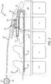
- FIG. 1shows a diagram of a view of an underside of an implantable electrode array assembly, according to an example embodiment of the present disclosure.
- FIG. 2shows a diagram of an enlarged view of a portion of the assembly of FIG. 1 , according to an example embodiment of the present disclosure.
- FIG. 3shows a diagram of a cross-sectional view of a cable system incorporating the assembly of FIG. 1 , according to an example embodiment of the present disclosure.
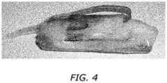
- FIG. 4shows a diagram of the cable system of FIG. 3 coated with a coating, according to an example embodiment of the present disclosure.
- FIG. 5shows a diagram of an example implant system including the implantable electrode array assembly and cable system of FIGS. 1 to 3 , according to an example embodiment of the present disclosure.
- FIG. 6shows a diagram of a multiplexer circuit, according to an example embodiment of the present disclosure.
- FIG. 7shows a diagram of a wireless power supply and a wireless power receiver, according to an example embodiment of the present disclosure.
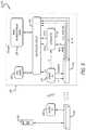
- FIG. 8shows a diagram of a controller, according to an example embodiment of the present disclosure.
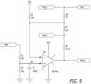
- FIG. 9shows a diagram of a stimulator, according to an example embodiment of the present disclosure.
- the present disclosurerelates in general to the field of neurological treatment and rehabilitation for injury and disease including traumatic spinal cord injury, non-traumatic spinal cord injury, stroke, movement disorders, brain injury, and other diseases or injuries that result in paralysis and/or nervous system disorder.
- Neuromodulation systems, devices, and methodsare provided to facilitate recovery of posture, locomotion, and voluntary movements such as those of the fingers, hands, arms, trunk, legs, and feet and recovery of autonomic, sexual, vasomotor, speech, swallowing, chewing, respiratory and cognitive function, in a human subject having spinal cord injury, brain injury, or any other neurological disorder or impairment.
- the systemscan include wireless communications.
- the neuromodulation systemscan include: a controller wirelessly communicatively coupled to a host computer; a signal generator communicatively coupled to the controller; and a plurality of electrodes communicatively coupled to the signal generator.
- the controllerin cooperation with the signal generator and the at least one electrode can be configured to deliver a stimulation to a mammal based on an instruction received from the host computer, the stimulation including being configured to induce voluntary movement or enable restoration of function.
- the use of conventional wire electrodes for spinal cord stimulationcan be effective in facilitating locomotor recovery in rats that have lower body paralysis.
- the use of a MEMS high-density microelectrode arraymay offer greater selectivity and flexibility in stimulation patterns, allowing for optimization of hindlimb stepping motion and better study of electrophysiological changes following the spinal cord injury.
- 37 wiresare needed for this passive implant and can often cause health complications.
- the present devicese.g., implants, and systems present a fully wireless spinal cord implant.
- this wireless implantcan be for mammals. In other embodiments, the implant can be for humans.
- This wireless spinal cord implantcan include an epidural microelectrode array and optional electrodes for evoked potentials and/or sensors.
- the herein described implantis capable or can be configured to both stimulate and record spinal cord, EMG responses, evoked potentials, sensory evoked potentials, or a type of physiological signal (i.e. electrical, chemical, photonic, mechanical, acoustic, etc.) from a subjects body or body parts (i.e. organ or organ system or the cells that make up the organ or organ system).
- the implantmay be part of a closed loop system.
- the implantmay communicate with other systems and devices either implanted or external to the body such as, for example, a pharmaceutical pump or a robotic system.
- the wireless implantcan include a 9 ⁇ 3 MEMS microelectrode array, a PCB with wireless microprocessor/transceiver, EMG wires, a power coil configured to receive power wirelessly, and sealing materials.
- the microelectrodeby way of a non-limiting example, can be fabricated with a parylene-metal-parylene sandwich structure.
- the microelectrodecan incorporate an improved microelectrode design and other additions to improve mechanical reliability and minimize delamination while retaining flexibility.
- the PCBcan fit 22 IC chips and about 100 passive components into a compact having a 10 mm ⁇ 32 mm footprint.
- the microelectrode arraycan include a plurality of electrodes. Each individual electrode within the plurality of electrodes can be pulsed or stimulated individually. In some embodiments, electrodes can be pulsed in pairs. A pair can include two or more individual electrodes group together. In some embodiments, an electrode or groups of electrodes can also be configured to record electrical signals.
- the stimulator associated with the wireless implantcan be configured to send a stimulating pulse to any pair of electrodes in the electrode array.
- the stimulator systemcan receive a signal or signals from one or more electrodes or pairs of electrodes (or other communicatively coupled sensors/devices/systems).
- the electrode arraycan include more than 2 electrodes, more than 5 electrodes, more than 10 electrodes, more than 15 electrodes, more than 20 electrodes, more than 25 electrodes, more than 30 electrodes, more than 50 electrodes, more than 100 electrodes, more than 500 electrodes, more than 1,000 electrodes, more than 5,000 electrodes, more than 10,000 electrodes, between about 2 electrodes and about 10,000 electrodes, between about 25 electrodes and about 35 electrodes, or between about 25 electrodes and about 100 electrodes.
- the electrode arraycan include 27 electrodes, 54 electrodes, 108 electrodes, 216 electrodes, or more.
- the circuitry encased in the wireless electrodecan switch between different electrode pairs very rapidly, this circuitry can be configured to effectively send an arbitrary pattern of pulses to a multi-electrode array or other electrode array as described herein.
- the systems describedcan address 27 electrodes, two reference wires, and 16 EMG wires.
- the systemscan include a maximum stimulating voltage.
- This maximum stimulating voltagecan be achieved in a constant voltage mode.
- Example stimulating voltagescan be about ⁇ 5 V, about ⁇ 6 V, about ⁇ 7 V, about ⁇ 8 V, about ⁇ 9 V, about ⁇ 10 V, about ⁇ 11 V, about ⁇ 12 V, about ⁇ 13 V, about ⁇ 14 V, about ⁇ 15 V, about ⁇ 20 V, at least about ⁇ 5 V, at least about ⁇ 10 V, at least about ⁇ 12 V, between about ⁇ 5 V and about ⁇ 20 V, or between about ⁇ 10 V and about ⁇ 15 V.
- the maximum stimulating voltagecan be ⁇ 12V.
- the systemscan include a maximum stimulating current.
- This maximum stimulating currentcan be achieved in a constant current mode.
- Maximum stimulating currentscan be about ⁇ 1 mA, about ⁇ 2 mA, about ⁇ 3 mA, about ⁇ 4 mA, about ⁇ 5 mA, about ⁇ 6 mA, about ⁇ 7 mA, about ⁇ 8 mA, about ⁇ 9 mA, about ⁇ 10 mA, at least about ⁇ 1 mA, at least about ⁇ 2 mA, at least about ⁇ 4 mA, between about ⁇ 1 mA and about ⁇ 10 mA, or between about ⁇ 4 mA and about ⁇ 6 mA.
- the maximum stimulating currentcan be ⁇ 5 mA.
- the systemscan provide an arbitrary waveform stimulation.
- Arbitrary waveform stimulationcan be about 10 kHz, about 20 kHz, about 30 kHz, about 40 kHz, about 50 kHz, about 60 kHz, about 70 kHz, about 80 kHz, about 90 kHz, about 100 kHz, about 110 kHz, about 120 kHz, about 130 kHz, about 140 kHz, about 150 kHz, about 160 kHz, about 170 kHz, about 180 kHz, about 190 kHz, about 200 kHz, at least about 50 kHz, at least about 80 kHz, at least about 90 kHz, between about 10 kHz and about 200 kHz, or between about 90 kHz and about 110 kHz.
- the arbitrary waveform stimulationcan be 100 kHz.
- the systemscan provide virtually any pulsed waveform.
- the pulsed waveformcan be as low as about 0.1 ms pulse width, as high as 50 kHz frequency with a recording bandwidth up to about 60 kHz ( ⁇ 3 dB).
- the herein described systemscan provide a digital-to-analog (DAC) resolution between about 5 bits and about 15 bits, between about 6 bits and about 13 bits, or between about 7 bits and about 12 bits.
- DACdigital-to-analog
- the systemscan have a characteristic configuration switch time.
- Characteristic switch timescan be about 1 ⁇ s, about 2 ⁇ s, about 3 ⁇ s, about 4 ⁇ s, about 5 ⁇ s, about 6 ⁇ s, about 7 ⁇ s, about 8 ⁇ s, about 9 ⁇ s, about 10 ⁇ s, less than about 10 ⁇ s, less than about 8 ⁇ s, less than about 4 ⁇ s, between about 1 ⁇ s and about 10 ⁇ s, or between about 2 ⁇ s and about 4 ⁇ s.
- the maximum stimulating currentcan be 3 ⁇ s.
- the systemscan configure and pulse a number of times per given time period.
- the systemscan configure and pulse about 10 times/millisecond (ms), about 20 times/ms, about 30 times/ms, about 40 times/ms, about 50 times/ms, about 60 times/ms, about 70 times/ms, about 80 times/ms, about 90 times/ms, about 100 times/ms, about 110 times/ms, about 120 times/ms, about 130 times/ms, about 140 times/ms, about 150 times/ms, about 160 times/ms, about 170 times/ms, about 180 times/ms, about 190 times/ms, about 200 times/ms, at least about 10 times/ms, at least about 20 times/ms, at least about 40 times/ms, at least about 60 times/ms, at least about 80 times/ms, at least about 100 times/ms, between about 10 times/ms and about 200 times/ms, or between about 90 times/ms and about 110 times//
- the systemscan be configured to simultaneously address a given number of electrodes.
- the electrodescan be arbitrary.
- the systemscan simultaneously address 2 electrodes, 4 electrodes, 6 electrodes, 8 electrodes, 10 electrodes, 12 electrodes, 14 electrodes, 16 electrodes, 18 electrodes, 20 electrodes, or any group of electrodes.
- the systemcan simultaneously address 2 arbitrary electrodes, 4 arbitrary electrodes, 6 arbitrary electrodes, 8 arbitrary electrodes, 10 arbitrary electrodes, 12 arbitrary electrodes, 14 arbitrary electrodes, 16 arbitrary electrodes, 18 arbitrary electrodes, 20 arbitrary electrodes, or more arbitrary electrodes.
- the systemscan simultaneously address up to 8 arbitrary electrodes with limited configuration flexibility.
- the systemscan be configured such that any two electrodes, if not used for stimulating, can be chosen as the differential pair for recording. Thus, any two electrodes not being used for stimulation can be used for recording.
- the recording electrodesare not limited to two at a time.
- the systemscan be configured to allow 4 electrodes, 6 electrodes, 8 electrodes, 10 electrodes, 12 electrodes, 14 electrodes, 16 electrodes, 18 electrodes, 20 electrodes, or more electrodes to be used for recording.
- the systemscan communicate wirelessly and possess characteristic data transfer rates.
- the systemscan have wireless data transfer rates of about 250 kBps, 500 kBps, 750 kBps, 1,000 kBps, at least 250 kBps, at least 500 kBps, between about 250 kBps and about 500 kBps, between about 250 kBps and about 1,000 kBps, or between about 250 kBps and about 750 kBps.
- These data ratescan be on ISM band 915 MHz.
- the systemscan have wireless data transfer rates of about 250 kBps.
- the systemscan also be configured as low power drawing systems.
- the max power consumption of the systemscan be less than about 100 mW, less than about 90 mW, less than about 80 mW, less than about 70 mW, less than about 60 mW, less than about 50 mW, less than about 40 mW, less than about 30 mW, or less than about 20 mW.
- the systemsuse less than about 100 mW of power when active.
- FIG. 1illustrates an implantable electrode array assembly 100 , according to an example embodiment of the present disclosure. While the embodiment of the assembly 100 illustrated is configured for implantation in a rat, embodiments may be constructed for use in other subjects, such as other mammals, including humans, and such embodiments are within the scope of the present teachings.
- the assembly 100is for use with a subject that has a spinal cord 330 (see FIG. 3 ) with at least one selected spinal circuit (not shown) and a neurologically derived paralysis in a portion of the subject's body.
- the assembly 100may be implanted epidurally along the spinal cord 330 .
- the assembly 100may be positioned at one or more of a sacral region, lumbosacral region, a lumbar region, a thoraco-lumbar region, a thoracic region, and/or a cervical region of the spinal cord 330 or a brainstem.
- the selected spinal circuitwhen activated, may (a) enable voluntary movement of muscles involved in at least one of standing, stepping, reaching, grasping, chewing, swallowing, breathing, voluntarily changing positions of one or both legs, voiding the subject's bladder, voiding the subject's bowel, postural activity, sitting, and locomotor activity; (b) enable or improve autonomic control of at least one of cardiovascular function, body temperature, and metabolic processes; and/or (c) help facilitate recovery of at least one of an autonomic function, sexual function, vasomotor function, and cognitive function.
- the selected spinal circuithas a first stimulation threshold representing a minimum amount of stimulation required to activate the selected spinal circuit, and a second stimulation threshold representing an amount of stimulation above which the selected spinal circuit is fully activated and adding the induced neurological signals has no additional effect on the at least one selected spinal circuit.
- the paralysismay be a motor complete paralysis or a motor incomplete paralysis.
- the paralysismay have been caused by a spinal cord injury classified as motor complete or motor incomplete.
- the paralysismay have been caused by an ischemic or traumatic brain injury.
- the paralysismay have been caused by an ischemic brain injury that resulted from a stroke or acute trauma.
- the paralysismay have been caused by a neurodegenerative brain injury.
- the neurodegenerative brain injurymay be associated with at least one of Parkinson's disease, Huntington's disease, Alzheimer's, ischemia, stroke, amyotrophic lateral sclerosis (ALS), primary lateral sclerosis (PLS), and cerebral palsy.
- the assembly 100may be implanted (e.g., epidurally) at a second location below the first location along the spinal cord relative to the subject's brain (not shown).
- the example assembly 100is configured to apply electrical stimulation to a portion of a spinal cord 330 of a subject.
- the electrical stimulationmay include at least one of tonic stimulation and intermittent stimulation.
- the stimulation appliedmay be pulsed.
- the electrical stimulationmay include simultaneous or sequential stimulation of different regions of the spinal cord.
- the electrical stimulation applied by the assembly 100may be below the second stimulation threshold such that the at least one selected spinal circuit is at least partially activatable by the addition of signals generated by the subject.
- such subject generated signalsmay be induced by subjecting the subject to physical activity or training (such as stepping on a treadmill). These signals may be induced in a paralyzed portion of the subject.
- the subject generated signalsmay include supraspinal signals.
- the assembly 100 illustrated in FIGS. 1 to 3can be configured for implantation in a rat.
- the implantcan be sized (e.g., about 59 mm by about 3 mm) and shaped for implantation into the rat.
- embodimentsmay be constructed for use with other subjects, such as other mammals, including humans.
- FIG. 2illustrates an enlarged portion 200 of the assembly 100 depicted in FIG. 1 , according to an example embodiment of the present disclosure.
- the assembly 100may be characterized as being a microelectromechanical systems (“MEMS”) device.
- MEMSmicroelectromechanical systems
- the assembly 100is configured for implantation along the spinal cord 330 (see FIG. 3 ) and to provide electrical stimulation thereto.
- the assembly 100may provide epidural stimulation to the spinal cord 330 .
- the assembly 100enables a high degree of freedom and specificity in selecting the site of stimulation compared to prior art wire-based implants, and triggers varied biological responses that can lead to an increased understanding of the spinal cord 330 and locomotive, movement, autonomic and functional recovery for victims of spinal cord injury.
- the assembly 100includes a body portion 110 , an electrode array 120 , and a plurality of electrically conductive traces 130 .
- the body portion 110includes a distal end portion 112 , a proximal end portion 114 (opposite the distal end portion), a frame 140 , and a grid structure 210 (see FIG. 2 ) for each electrode E 11 -E 19 , E 21 -E 29 , and E 31 -E 39 of the electrode array 120 .
- Each of the grid structures 210defines a plurality of cells 212 .
- the grid structures 210may each be constructed from parylene (e.g., parylene-C). In the embodiment illustrated, the grid structure 210 includes 40 cells.
- the electrode array 120includes the plurality of electrodes E 11 -E 19 , E 21 -E 29 , and E 31 -E 39 (e.g., 9 ⁇ 3 electrodes).
- the electrodes E 11 -E 19 , E 21 -E 29 , and E 31 -E 39are arranged in a two-dimensional array.
- Each of the electrodes E 11 -E 19 , E 21 -E 29 , and E 31 -E 39includes a plurality of electrically conductive contacts 220 .
- the contacts 220are sites at which the electrode (e.g., the electrode E 37 illustrated in FIG. 2 ) will contact the spinal cord (e.g., the dura).
- the contacts 220are in electrically communication with one another.
- each of the electrodes E 11 -E 19 , E 21 -E 29 , and E 31 -E 39corresponds to a unique one of the grid structures 210 .
- each of the contacts 220is positioned within a different one of the cells 212 of the corresponding grid structure 210 .
- the grid structure 210may help prevent delamination of the layers of the assembly 100 (see FIG. 1 ).
- the grid structure 210 and contacts 220may be formed by selectively etching a layer of substantially electrically non-conductive material (e.g., parylene) adjacent a pad of electrically conductive material (e.g., metal such as platinum or gold) to define the grid structure 210 and expose portions of the electrically conductive material within the cells 212 of the grid structure to define the contacts 220 .
- substantially electrically non-conductive materiale.g., parylene
- electrically conductive materiale.g., metal such as platinum or gold
- the electrode array 120 illustratedincludes 27 electrodes, in other embodiments, the number of electrodes may range from one electrode to about 1000 electrodes or more. As discussed above, the electrode array 120 includes at least 10, at least 15, at least 20, at least 25, at least 50, at least 100, at least 250, at least 500, or at least 1000 electrodes. In various embodiments, the inter-electrode spacing of adjacent electrodes in the electrode array 120 varies from about 100 ⁇ m or about 500 ⁇ m, or about 1000 ⁇ m or about 1500 ⁇ m to about 2000 ⁇ m, or about 3000 ⁇ m, or about 4000 ⁇ m, or about 4500 ⁇ m, or about 5000 ⁇ m.
- inter-electrode spacingranges from about 100 ⁇ m, about 150 ⁇ m, about 200 ⁇ m, or about 250 ⁇ m up to about 1,000 ⁇ m, about 2000 ⁇ m, about 3000 ⁇ m, or about 4,000 ⁇ m.
- the diameter (or width) of each of the electrodes E 11 -E 19 , E 21 -E 29 , and E 31 -E 39ranges from about 50 ⁇ m, 100 ⁇ m, 150 ⁇ m, 200 ⁇ m, or 250 ⁇ m up to about 500 ⁇ m, about 1000 ⁇ m, about 1500 ⁇ m, or about 2000 ⁇ m.
- the electrode array 120can be formed in any geometric shape such as a square shape, rectangular shape, circular shape, tubular shape, fan shape, or fusiform shape. Typically the size of the electrode array 120 will be on the order of about 0.1 mm to about 2 cm, wide or in diameter, depending in part on the number of electrodes in the electrode array 120 . In various embodiments, the length of the electrode array 120 ranges from about 0.01 mm, or 0.1 mm up to about 10 cm or greater.
- One or more of the traces 130is connected to each of the electrodes E 11 -E 19 , E 21 -E 29 , and E 31 -E 39 .
- two traces “T 1 ” and “T 2 ”are connected to each of the electrodes E 11 -E 19 , E 21 -E 29 , and E 31 -E 39 .
- more than two traces 130may be connected to each of the electrodes E 11 -E 19 , E 21 -E 29 , and E 31 -E 39 .
- Connecting more than one of the traces 130 to each of the electrodes E 11 -E 19 , E 21 -E 29 , and E 31 -E 39helps ensure signals reach each of the electrodes E 11 -E 19 , E 21 -E 29 , and E 31 -E 39 . In other words, redundancy may be used to improve reliability.
- the traces 130are connected to each of the contacts 220 of the electrode and carry or receive signals thereto. Openings 132 (see FIG. 3 ) formed (e.g., etched) in the body portion 110 expose portions of the traces 130 .
- the traces 130may be used to selectively deliver electrical signals (e.g., pulsed signals) to (or record signals from) the electrodes E 11 -E 19 , E 21 -E 29 , and E 31 -E 39 . In this manner, only a selected one or more of the electrodes (or pair of electrodes) E 11 -E 19 , E 21 -E 29 , and E 31 -E 39 may deliver stimulation to the spinal cord 330 (see FIG. 3 ).
- the electrodes E 11 -E 19 , E 21 -E 29 , and E 31 -E 39are operably linked by the traces 130 to control circuitry, as discussed in further detail below.
- the control circuitryis configured to select one or more of the electrodes E 11 -E 19 , E 21 -E 29 , and E 31 -E 39 to activate/stimulate/record and/or to control the parameters (e.g., frequency, pulse width, amplitude, etc.) of the electrical stimulation.
- the electrode selection, frequency, amplitude, and pulse widthare independently selectable. For example, at different times, different electrodes can be selected. At any time, different electrodes can provide stimulation having different parameter values (e.g., frequencies, amplitudes, and the like).
- at least a portion of the electrodesmay be operated in a monopolar mode and/or a bipolar mode. In such embodiments, constant current or constant voltage may be used to deliver the stimulation.
- the traces 130may receive signals from implantable control circuitry and/or an implantable power source (not shown).
- the implantable control circuitrymay be programmed and/or reprogrammed by an external device (e.g., using a handheld device that communicates with the control circuitry through the skin). The programming may be repeated as often as necessary.
- FIG. 3illustrates a cable system 300 incorporating the assembly 100 of FIG. 1 , according to an example embodiment of the present disclosure.
- the example cable system 300is illustrated implanted along the spine 320 and spinal cord 330 of a rat.
- the cable system 300is composed of a spinal baseplate 340 , EMG wires 350 , and/or EMG electrodes 310 .
- the baseplate 340may be constructed from a FR-4 PCB substrate.
- the baseplate 340is attached (e.g., by a suture 342 ) to a selected vertebrae (e.g., vertebrae “L2”). In the embodiment illustrated, the baseplate 340 is attached to the “L2” vertebrae.
- the assembly 100is attached (e.g., by a suture 344 ) to the spinal cord 300 .
- the distal end portion 112 of the assembly 100is attached to the spinal cord 300 at a location adjacent vertebrae “T13.”
- the proximal end portion 114 of the assembly 100is attached to the baseplate 340 using a conductive material (e.g., conductive epoxy) to bridge electrical connections.
- a conductive materiale.g., conductive epoxy
- the proximal end portion 114 of the assembly 100may be secured to the baseplate 340 using Loctite M-121HP Medical device epoxy.
- the example EMG wires 350may be connected to hind limbs or other structure of a subject for inducing electrical stimulation or recording one or more signals.
- the EMG wires 350may be connected to or include one or more EMG electrodes 310 .
- the EMG wires 350may be replaced with connections to other types of electrodes, sensors, and/or systems/devices either wired or wireless, or may also be omitted.
- the EMG wires 350include a plurality of wires 352 .
- the wires 352may each be connected to a separate electrode 310 .
- Each of the wires 352may be constructed from gold and include a Teflon coating.
- 75 ⁇ m gold wirese.g., Teflon coated gold wire manufactured by AM Systems
- the wires 352may be soldered to the baseplate 340 and connected by high density connectors 360 to the respective electrodes 310 .
- the traces 130are connected to the baseplate 340 via the openings 132 formed in the body portion 110 of the assembly 100 .
- silver epoxy(not shown) may be used to connect the traces 130 to the baseplate 340 .
- the entire cable system 300may be coated with a coating 370 configured to insulate electrical connections and provide mechanical strength while retaining the flexibility wherever necessary.
- the implants described hereincan be covered and/or sealed to prevent exposure of the implant or portions of the implant to tissues. In some embodiments, the entire implant can be covered or sealed. In other embodiments, substantially all of the implant is coated or sealed.
- the implantcan be sealed using a combination of parylene, an epoxy and a silicone.
- the implantcan be sealed by coating it in silicone.
- an epoxycan be used to seal the implant
- parylenecan be used to seal the implant. Parylene is used to describe a variety of chemical vapor deposited poly(p-xylylene) polymers used as moisture and dielectric barriers.
- parylene-Cis used to seal the implant. Combinations of epoxy, parylene and silicone can be used to seal the implant.
- the coating 370may include a biomedical grade epoxy and a silicone elastomer (e.g., MDX 4-4210 Biomedical grade silicone).
- hermetic metal packagingcannot satisfy size and feed-through requirements for the presently described wireless implants.
- New metal packaging and feed-through assembliescan be mechanically designed, manufactured and incorporated.
- a new sealing techniquecan be used to encase the wireless implants.
- the technique used to seal the wireless implantscan use parylene-C, epoxy, and/or silicone.
- components of the implantcan be attached using an epoxy and then completely coated with silicone. In other embodiments, components of the implant can be attached using an epoxy and then completely coated with parylene.
- the implantcan be coated by methods such as dipping, brushing, spray coating, rolling, vapor deposition, and the like. In one example embodiment, the implant can be sealed by dipping the implant in a coating solution.
- the coating solutioncan include epoxy, silicone, and/or parylene. In some embodiments, the implant can be covered in an epoxy, for example, by dipping and then coated with parylene, silicone or a combination thereof.
- the sealed wireless implantcan remain sealed in vivo for a useful lifetime of the implant.
- the wireless implantcan remain sealed for at least one month, at least two months, at least three months, at least four months, at least five months, at least six months, at least one year, at least two years, at least five years, between about two months and about 5 years, between about 1 year and about 5 years, or between about 6 months and about 5 years.
- the technique of sealing the wireless implantcan provide sufficient sealing for at least two months of in vivo functionality.
- a silicone cap 380(or overhanging portion) is formed on the end of the baseplate 340 to protect the assembly 100 from external moving tissue.
- the cap 380may be formed from the same material as the coating 370 .
- the coating 370may be implemented as a thin layer of silicone (e.g., about 100 ⁇ m thick) to reduce stress concentration as the assembly 100 bends with the subject's spine 320 during movement.
- a thicker layer of silicone applied to the assembly 100may be detrimental to the health of the spinal cord 330 because of increased pressure that is applied by a more rigid assembly to the spinal cord. In other words, flexibility may be an important feature of a successful chronic implantable electrode array assembly.
- FIG. 5shows a diagram of an example implant system 500 , according to an example embodiment of the present disclosure.
- the example implant system 500includes the example implantable electrode array assembly 100 discussed above in conjunction with FIGS. 1 to 4 .
- the system 500also includes a host computer 502 that is configured to be communicatively coupled to the implantable electrode array assembly 100 .
- the example host computer 502may include any computer, laptop computer, server, workstation, processor, tablet computer, smartphone, smart-eyewear, smart-watch, lab instrument, etc.
- the host computer 502may be centralized or distributed via a network or cloud computing environment.
- the host computer 502may include an interface, which enables remote devices (e.g., smartphones) to remotely specify data (or instructions) to be transmitted to the implantable electrode array assembly 100 and view data received from the implantable electrode array assembly 100 .
- the example host computer 502is configured to determine and/or control data streams for transmission to the implantable electrode array assembly 100 .
- a usermay specify the data streams (or instructions) to be transmitted.
- the host computer 502may include machine-readable instructions, which when executed, cause the host computer 502 to operate one or more algorithms for determining data streams to be transmitted to the implantable electrode array assembly 100 .
- the host computer 502is also configured to receive, process, and/or analyze data streams from the implantable electrode array assembly 100 .
- the host computer 502may include machine-readable instructions, which when executed, cause the host computer 502 to operate one or more algorithms that analyze received data streams from the implantable electrode array assembly 100 .
- the host computer 502may also be configured to provide a graphical representation indicative of the data streams transmitted to the implantable electrode array assembly 100 and/or a graphical representation indicative of the data streams received from the implantable electrode array assembly 100 .
- the example implant system 500includes a controller 504 .
- the example implant system 500may include a controller 504 .
- the example controller 504includes a transceiver configured to convert communications from the host computer 502 into a wireless format (e.g., a low power RF format, Bluetooth®, Zigbee®, etc.) for transmission to the assembly 100 .
- the example controller 504is also configured to receive wireless signals (e.g., wireless streams of data) from the assembly 100 and convert the wireless signals into a format compatible for the host computer 502 .
- the controller 504is communicatively coupled to the host computer 502 via a Universal Serial Bus (“USB”). In other embodiments, the controller 504 is communicatively coupled wirelessly to the host computer 502 .
- the controller 504may also include memory to buffer or queue data streams for transmission.
- the controller 504(by way of a non-limiting example) may include the Texas Instruments® CC1111 Sub-1 GHz RF System-on-Chip.
- the example system 500also includes a wireless power supply 506 configured to provide wireless power to the assembly 100 .
- the power supply 506is communicatively coupled to at least one of the host computer 502 and/or the controller 504 to receive power control instructions.
- the example wireless power supply 506may include a Class E amplifier and inductive coupling components to enable wireless transmission of power to the assembly 100 (as discussed further in conjunction with FIG. 7 ).
- the example wireless power supply 506may also include a variable output to enable the amount of power provided to the assembly 100 to be adjusted based on, for example, application of the assembly 100 , power requirements of the assembly 100 , and/or operations being performed by the assembly 100 .
- the host computer 502may instruct the wireless power supply 506 to output relatively more wireless power when relatively more stimulation signals are to be provided by the assembly 100 .
- the example implantable electrode array assembly 100includes EMG wires 350 , a MEMS microelectrode array 120 , and implantable control circuitry.
- the implantable control circuitryincludes a multiplexer circuit 508 , a wireless power receiver 510 , a stimulator 512 (e.g., a signal generator/receiver), and a controller 514 . It should be appreciated that the implantable control circuitry of the assembly 100 may include additional or fewer components.
- the implantable control circuitrymay also include a battery for long term storage of power from the wireless power supply 506 , a memory to store instructions for operation of the implantable control circuitry, a memory to store data streams transmitted from the host computer 502 and/or detected by the assembly 100 , etc.
- the implantable control circuitry of FIG. 5may be combined and/or partitioned differently based on hardware used, application, etc.
- the example wireless power receiver 510(discussed further in conjunction with FIG. 7 ) is configured to receive wireless power from the wireless power supply 506 and convert the wireless power into a DC voltage.
- the wireless power receiver 510is configured to output 3 V DC and 12 V DC. In other embodiments, the wireless power receiver 510 may output 5 V DC. It should be appreciated that the wireless power receiver 510 may be configured to output one or more different DC voltages having any magnitude based, for example, on power requirements of the other implantable control circuitry, electromagnetic considerations of the assembly, etc.
- the wireless power receiver 510may also output an AC signal and/or a power monitor signal (e.g., PWRMON) based on requirements of the implantable control circuitry. For instance, the wireless power receiver 510 is configured to output a power monitor signal to the controller 514 to enable the controller 514 to monitor power received from the wireless power supply 506 .
- PWRMONpower monitor signal
- the example controller 514(discussed further in conjunction with FIG. 8 ) is configured to operate instructions that control the multiplexer circuit 508 and/or the stimulator 512 .
- the controller 514includes a transceiver configured to receive a data stream wirelessly from the controller 504 and convert the wireless data stream for processing.
- the example controller 514may also include instructions that instruct the controller 514 how to control the multiplexer circuit 508 and/or the stimulator 512 based on the data stream generated by the host computer 502 .
- the controller 514transmits the appropriate signal (e.g., appropriate digital word) via Clock, Data, and EN (enable) lines to the multiplexer circuit 508 to cause the specified waveform (e.g., stimulation signal) to be provided by the E 13 and E 33 electrode pair of the MEMS microelectrode array 120 .
- the appropriate signale.g., appropriate digital word
- Clock, Data, and EN (enable) linesto the multiplexer circuit 508 to cause the specified waveform (e.g., stimulation signal) to be provided by the E 13 and E 33 electrode pair of the MEMS microelectrode array 120 .
- the example controller 514is configured to be programmed with operating instructions from the host computer 502 via the controller 504 .
- the operating instructionsmay specify the stimulation signal(s) and timing that is to be controlled and/or managed by the controller 514 .
- Such a configurationenables the controller 514 to provide stimulation signals as specified without having the controller 504 and/or host computer 502 in constant contact or proximity of the subject.
- the example controller 514can also be configured to record amplified signals (e.g., signals A 1 -A 4 ) received from the EMG wires 350 , EMG electrodes 310 , the MEMS microelectrode array 120 , or other electrodes, sensors, or systems.
- amplified signalse.g., signals A 1 -A 4
- a sensor or systemmay wirelessly provide an indication of a recoded signal.
- the host computer 502may specify within a data stream that electrodes E 18 and E 39 are to sense or otherwise detect an electrical signal after stimulation by another electrode pair.
- the controller 514is configured to transmit the appropriate signal (e.g., appropriate digital word) via Clock, Data, and EN (enable) lines to the multiplexer circuit 508 to cause voltages detected by the E 18 and E 39 electrodes of the MEMS microelectrode array 120 to be amplified and recorded.
- the host computer 502may specify within a data stream that electrodes and/or sensors 350 are to record signal(s).
- the controller 514is configured to transmit the appropriate signal (e.g., appropriate digital word) via Clock, Data, and EN (enable) lines to the multiplexer circuit 508 to cause voltages detected by the electrodes and/or sensors to be amplified and recorded.
- the controller 514may then transmit the recorded data via a data stream to the transceiver 504 .
- the example controller 514can also be configured to monitor the wireless power received at the wireless power receiver 510 .
- the controller 514is configured to enable that enough power is provided to enable the multiplexer circuit 508 to output the specified stimulating pulses to the subject.
- the controller 514may receive within a data stream a sequence of pulses to be applied to the subject and determine that the power being received at the wireless power receiver 510 is insufficient.
- the controller 514may transmit a message to the transceiver 504 for additional power (or an amount of additional power needed), which causes the controller 504 to increase the amount of power output by the wireless power supply 506 .
- the controller 514may include the Texas Instruments® CC1111 Sub-1 GHz RF System-on-Chip.
- the example stimulator 512(discussed further in conjunction with FIG. 9 ) is configured to provide a constant voltage and/or current to the multiplexer circuit 508 .
- the constant voltage and/or currentis provided via a Stim+ and a Stim ⁇ signal lines to the multiplexer circuit 508 .
- the amount of voltage and/or current provided by the stimulator 512may be set via a pulse width modulation (“PWM”) signal from the controller 514 .
- PWMpulse width modulation
- the amount of voltage providedmay be based on a stimulation signal specified by the host computer 502 .
- a mode between voltage and current outputmay be set via a mode signal from the controller 514 .
- the example multiplexer circuit 508is configured to route connections between the stimulator 512 and/or amplifiers and the EMG wires 350 , the EMG electrodes 310 , the MEMS microelectrode array 120 , or other types of electrodes, sensors, systems, devices, etc.
- FIG. 6shows a diagram of the multiplexer circuit 508 , according to an example embodiment of the present disclosure.
- the example multiplexer circuit 508includes multiplexers M 0 , M 1 , M 2 , M 3 , M 4 , M 5 , M 6 , M 7 , M 8 , and M 9 , which may include Analog Devices® ADG1209 or ADG1208 multiplexers.
- the multiplexer circuit 508also includes shift registers SR 1 , SR 2 , SR 3 , and SR 4 , which may include NXP Semiconductors® 74HC164 shift registers.
- the multiplexer circuit 508further includes amplifiers AMP 1 , AMP 2 , AMP 3 , and AMP 4 , which may include Analog Devices AD8224 amplifiers.
- the multiplexer circuit 508receives as control inputs from the controller 514 Clock, Data, and EN, which specify which of the EMG wires 350 , the EMG electrodes 310 , the electrode pair within MEMS microelectrode array 120 , or other types of electrodes, sensors, systems, devices, etc. are to be configured to output a stimulation signal (e.g., Stim+ or Stim ⁇ ) and/or configured to receive an electrical signal.
- the multiplexer circuit 508receives the stimulation signals Stim+ and Stim ⁇ from the stimulator 512 .
- the desired configurationcan be achieved by sending, for example, a 30-bit serial data stream through the Clock and Data inputs into the shift registers SR 1 to SR 4 .
- the example shift registers SR 1 to SR 4in turn control or select which output of the multiplexers M 1 to M 9 are to receive and output the Stim+ and Stim ⁇ signals.
- the EN signalis used by the controller 514 to enable the multiplexers M 0 to M 9 .
- the example multiplexer M 0is configured to disconnect the stimulation wires to the multiplexers M 1 to M 9 in instances where the controller 514 instructs the multiplexer circuit 508 to configure the EMG wires 350 and/or the MEMS microelectrode array 120 to record.
- the multiplexer M 0is also configured to select a polarity of the stimulation signal to be provided to any one of the multiplexers M 1 to M 9 in instances where the controller 514 instructs that a stimulation signal is to be output to a subject.
- the example multiplexers M 1 to M 9are configured to receive control signals from the shift registers SR 1 to SR 4 to determine which output is to receive a stimulation signal. As shown in FIG. 6 , the multiplexers M 1 to M 9 are interconnected to enable almost any two of the electrodes within the MEMS microelectrode array 120 , the EMG wires 350 , the EMG electrodes 310 , or other types of electrodes, sensors, systems, devices, etc. to be selected for outputting a stimulation signal or detecting an electrical signal within the subject. The illustrated embodiment shows the multiplexers M 1 to M 9 connected to an electrodes designated by an alpha-numeric identifier.
- the letter “E”refers to an EMG wire 350 where “E #+” and “E #” are EMG wire pairs.
- the letters “A”, “B”, and “C”refer to spinal cord electrode columns shown in FIG. 1 , where the letter “A” corresponds to column 1 , the letter “B’ corresponds to column 2 , and the letter “C” corresponds to the column 3 .
- a 3refers to the electrode E 13 of the MEMS microelectrode array 120 of FIG. 1 .
- Outputs G 1 and G 2refer to reference wires placed, for example, near the shoulder and the lower back respectively on a subject.
- the multiplexer M 1is configured to be selectively connected to E 1 +, E 5 +, A 5 , B 8 , and C 2 .
- the multiplexer M 2is configured to be selectively connected to E 1 ⁇ , E 55 , A 4 , B 7 , and C 5 .
- the multiplexer M 3is configured to be selectively connected to E 2 +, E 6 +, A 3 , B 6 , and C 8 .
- the multiplexer M 4is configured to be selectively connected to E 2 ⁇ , E 6 ⁇ , A 2 , B 5 , and C 7 .
- the multiplexer M 5is configured to be selectively connected to E 3 +, E 7 +, A 1 , B 4 , C 6 , and A 9 .
- the multiplexer M 6is configured to be selectively connected to E 3 ⁇ , E 7 ⁇ , A 8 , B 3 , C 1 , and C 9 .
- the multiplexer M 7is configured to be selectively connected to E 4 +, E 8 +, A 7 , B 2 , and C 4 .
- the multiplexer M 8is configured to be selectively connected to E 4 ⁇ , E 8 ⁇ , A 6 , B 1 , C 3 , and B 9 .
- the multiplexer M 9is configured to be selectively connected to G 1 , G 2 , A 1 , B 1 , C 1 , A 9 , B 9 , and C 9 .
- some key electrodese.g., the electrodes corresponding to A 9 , B 9 , and C 9
- the number of multiplexers and/or multiplexer outputsmay change based on the number of EMG wires 350 and/or electrodes within the MEMS microelectrode array 120 .
- the example amplifiers AMP 1 to AMP 4are configured to amplify a differential signal received from selected ones of the EMG wires 350 , the EMG electrodes 310 , electrodes within the MEMS microelectrode array 120 , and/or other types of electrodes, sensors, systems, devices, etc.
- Each of the amplifiers AMP 1 to AMP 4may be configured to have a gain of 200 and output respective signals A 1 to A 4 representative of detected electrical pulses within a subject.
- the controller 514may instruct the multiplexer circuit 508 to enter a ‘listen mode’ where the E 1 + and E 1 ⁇ EMG wires 350 and/or EMG electrodes 310 (or other types of electrodes, sensors, systems, devices, etc.) are set to record or otherwise sense an electrical signal and convey this signal via multiplexers M 1 and M 2 to one or more of the amplifiers AMP 1 to AMP 4 , for transmission to the controller 514 .
- the controller 514may instruct the multiplexer circuit 508 to enter a ‘listen mode’ where the E 1 + and E 1 ⁇ EMG wires 350 and/or EMG electrodes 310 (or other types of electrodes, sensors, systems, devices, etc.) are set to record or otherwise sense an electrical signal and convey this signal via multiplexers M 1 and M 2 to one or more of the amplifiers AMP 1 to AMP 4 , for transmission to the controller 514 .
- the example multiplexer circuit 508 of FIG. 6may be configured to operate in four different modes to meet experimental requirements.
- a first modeenables a simulation signal to be applied by any two electrodes within the MEMS microelectrode array 120 , the EMG wires 350 , and/or the EMG electrodes 310 .
- a second modeenables the multiplexer circuit 508 to record from any four EMG wire pairs, EMG electrodes, or other types of electrodes, sensors, systems, devices, etc.
- a third modeenables the multiplexer circuit 508 to record from any two electrodes within the array 120 .
- a fourth modeenables the multiplexer circuit 508 to record from four electrodes of the same column within the array 120 with respect to a fifth electrode.
- the example multiplexer circuit 508is configured to switch between the different modes and configurations of selected electrodes of the array 120 and/or EMG wires 350 or EMG electrodes 310 within 1 microsecond, thereby enabling the Stim+ and Stim ⁇ stimulation signals to delivery relatively short pulses to many electrodes and/or EMG wires or EMG electrodes in a one millisecond timeframe. Such a configuration also enables the amplifiers AMP 1 to AMP 4 to rapidly switch input signals to effectively record from eight or sixteen signals instead of four within a specified timeframe.
- FIG. 7shows a diagram of the example wireless power supply 506 and the wireless power receiver 510 of FIG. 5 , according to an example embodiment of the present disclosure.
- the example wireless power supply 506uses inductor L 1 to convert power provided by supply V 1 for transmission via a wireless medium.
- the wireless power supply 506also includes circuitry to convert the voltage from supply V 1 into an AC signal.
- the example wireless power supply 510uses indictor L 2 to receive the power and convert the power into an AC signal.
- the wireless power supply 510also includes a voltage regulator U 2 and circuitry D 1 , D 2 , C 9 , and C 10 configured to convert or rectify the AC signal into one or more DC voltages (e.g., 3 V and 12 V).
- FIG. 8shows a diagram of the example controller 514 of FIG. 5 , according to an example embodiment of the present disclosure.
- the example controller 514is wirelessly communicatively coupled to the controller 504 via antenna E 1 and corresponding circuitry. As described above in conjunction with FIGS. 5 and 6 , the example controller 514 is configured to instruct the stimulator 512 to operate in a voltage or current mode via the Mode 1 and Mode 2 outputs and instruct the multiplexer circuit 508 via the Clock, Data, and EN outputs.
- the example controller 514receives one or more detected signals via inputs A 1 to A 4 .
- the example controller 514may include memory to enable instructions to be stored from the host computer 502 specifying how and types of stimulation pulses are to be applied to a subject.
- the example controller 514may include memory to enable instructions to be stored from the host computer 502 specifying which electrodes and/or EMG wires/electrodes (or other types of electrodes, sensors, systems, devices, etc.) are to be used for recording electrical signals.
- the example controller 514may include memory to store a data structure of operations including when pulses were applied and data representative of data received via inputs A 1 to A 4 .
- FIG. 9shows a diagram of the example stimulator 512 of FIG. 5 , according to an example embodiment of the present disclosure.
- the example stimulator 512is configured to receive a Mode 1 signal and a Mode 2 signal from the controller 514 and accordingly output a constant voltage or constant current via Stim+ and Stim ⁇ signal lines. For instance, if the Mode 1 signal is set to ground and Mode 2 is set to a high impedance, then the stimulator 512 is configured to operate in a constant voltage mode. Alternatively, if the Mode 1 signal is set to a high impedance and Mode 2 is set to ground, then the stimulator 512 is configured to operate in a constant current mode. The magnitude of the voltage and/or current may be set via a PWM signal from the controller 514 .
Landscapes
- Health & Medical Sciences (AREA)
- Life Sciences & Earth Sciences (AREA)
- Engineering & Computer Science (AREA)
- General Health & Medical Sciences (AREA)
- Biomedical Technology (AREA)
- Veterinary Medicine (AREA)
- Public Health (AREA)
- Animal Behavior & Ethology (AREA)
- Neurosurgery (AREA)
- Neurology (AREA)
- Radiology & Medical Imaging (AREA)
- Nuclear Medicine, Radiotherapy & Molecular Imaging (AREA)
- Heart & Thoracic Surgery (AREA)
- Biophysics (AREA)
- Physics & Mathematics (AREA)
- Surgery (AREA)
- Molecular Biology (AREA)
- Medical Informatics (AREA)
- Pathology (AREA)
- Physical Education & Sports Medicine (AREA)
- Rehabilitation Therapy (AREA)
- Physiology (AREA)
- Hospice & Palliative Care (AREA)
- Orthopedic Medicine & Surgery (AREA)
- Cardiology (AREA)
- Computer Networks & Wireless Communication (AREA)
- Electrotherapy Devices (AREA)
- Acoustics & Sound (AREA)
- Pulmonology (AREA)
Abstract
Description
Claims (20)
Priority Applications (1)
| Application Number | Priority Date | Filing Date | Title |
|---|---|---|---|
| US15/713,456US10786673B2 (en) | 2014-01-13 | 2017-09-22 | Neuromodulation systems and methods of using same |
Applications Claiming Priority (3)
| Application Number | Priority Date | Filing Date | Title |
|---|---|---|---|
| US201461926457P | 2014-01-13 | 2014-01-13 | |
| US14/596,118US20150217120A1 (en) | 2014-01-13 | 2015-01-13 | Neuromodulation systems and methods of using same |
| US15/713,456US10786673B2 (en) | 2014-01-13 | 2017-09-22 | Neuromodulation systems and methods of using same |
Related Parent Applications (1)
| Application Number | Title | Priority Date | Filing Date |
|---|---|---|---|
| US14/596,118ContinuationUS20150217120A1 (en) | 2014-01-13 | 2015-01-13 | Neuromodulation systems and methods of using same |
Publications (2)
| Publication Number | Publication Date |
|---|---|
| US20180185648A1 US20180185648A1 (en) | 2018-07-05 |
| US10786673B2true US10786673B2 (en) | 2020-09-29 |
Family
ID=53524428
Family Applications (2)
| Application Number | Title | Priority Date | Filing Date |
|---|---|---|---|
| US14/596,118AbandonedUS20150217120A1 (en) | 2014-01-13 | 2015-01-13 | Neuromodulation systems and methods of using same |
| US15/713,456ActiveUS10786673B2 (en) | 2014-01-13 | 2017-09-22 | Neuromodulation systems and methods of using same |
Family Applications Before (1)
| Application Number | Title | Priority Date | Filing Date |
|---|---|---|---|
| US14/596,118AbandonedUS20150217120A1 (en) | 2014-01-13 | 2015-01-13 | Neuromodulation systems and methods of using same |
Country Status (2)
| Country | Link |
|---|---|
| US (2) | US20150217120A1 (en) |
| WO (1) | WO2015106286A1 (en) |
Families Citing this family (24)
| Publication number | Priority date | Publication date | Assignee | Title |
|---|---|---|---|---|
| EP2661307A4 (en) | 2011-01-03 | 2014-08-06 | Univ California | HIGH DENSITY EPIDURAL STIMULATION TO FACILITATE LOCOMOTION, POSTURE, VOLUNTARY MOVEMENT AND RECOVERY OF SEXUAL, VASOMOTOR AND COGNITIVE AUTONOMY FUNCTION AFTER NEUROLOGICAL INJURY |
| KR20140038940A (en) | 2011-01-21 | 2014-03-31 | 캘리포니아 인스티튜트 오브 테크놀로지 | A parylene-based microelectrode array implant for spinal cord stimulation |
| EP2688642B1 (en) | 2011-03-24 | 2022-05-11 | California Institute of Technology | Neurostimulator |
| US10092750B2 (en) | 2011-11-11 | 2018-10-09 | Neuroenabling Technologies, Inc. | Transcutaneous neuromodulation system and methods of using same |
| EP2776120B1 (en) | 2011-11-11 | 2020-09-09 | Neuroenabling Technologies, Inc. | Non invasive neuromodulation device for enabling recovery of motor, sensory, autonomic, sexual, vasomotor and cognitive function |
| WO2014144785A1 (en) | 2013-03-15 | 2014-09-18 | The Regents Of The University Of California | Multi-site transcutaneous electrical stimulation of the spinal cord for facilitation of locomotion |
| US10137299B2 (en) | 2013-09-27 | 2018-11-27 | The Regents Of The University Of California | Engaging the cervical spinal cord circuitry to re-enable volitional control of hand function in tetraplegic subjects |
| WO2015106286A1 (en) | 2014-01-13 | 2015-07-16 | California Institute Of Technology | Neuromodulation systems and methods of using same |
| US20160175586A1 (en)* | 2014-10-10 | 2016-06-23 | Neurorecovery Technologies, Inc. | Epidural stimulation for facilitation of locomotion, posture, voluntary movement, and recovery of autonomic, sexual, vasomotor, and cognitive function after neurological injury |
| AU2016293999B2 (en)* | 2015-07-10 | 2020-07-16 | Neuronano Ab | Method and system for improving stimulation of excitable tissue |
| WO2017091828A1 (en)* | 2015-11-29 | 2017-06-01 | The Regents Of The University Of California | Disposable gastrointestinal implantable stimulator |
| RU2627359C2 (en)* | 2015-12-29 | 2017-08-07 | Общество с ограниченной ответственностью "Косима" (ООО "Косима") | Device for noninvasive electric stimulation of the spinal cord |
| US11235154B2 (en) | 2017-02-17 | 2022-02-01 | The University Of British Columbia | Apparatus and methods for maintaining physiological functions |
| WO2018217791A1 (en) | 2017-05-23 | 2018-11-29 | The Regents Of The University Of California | Accessing spinal networks to address sexual dysfunction |
| GB201708654D0 (en)* | 2017-05-31 | 2017-07-12 | Verity Nigel Charles | Apparatus and process for neuromuscular stimulation |
| EP3974021B1 (en) | 2017-06-30 | 2023-06-14 | ONWARD Medical N.V. | A system for neuromodulation |
| US12357828B2 (en) | 2017-12-05 | 2025-07-15 | Ecole Polytechnique Federale De Lausanne (Epfl) | System for planning and/or providing neuromodulation |
| WO2019110400A1 (en) | 2017-12-05 | 2019-06-13 | Ecole Polytechnique Federale De Lausanne (Epfl) | A system for planning and/or providing neuromodulation |
| US11464964B2 (en)* | 2018-08-03 | 2022-10-11 | Brown University | Neural interrogation platform |
| EP3653260A1 (en) | 2018-11-13 | 2020-05-20 | GTX medical B.V. | Sensor in clothing of limbs or footwear |
| DE18205821T1 (en) | 2018-11-13 | 2020-12-24 | Gtx Medical B.V. | CONTROL SYSTEM FOR MOTION RECONSTRUCTION AND / OR RECOVERY FOR A PATIENT |
| EP3695878B1 (en) | 2019-02-12 | 2023-04-19 | ONWARD Medical N.V. | A system for neuromodulation |
| DE19211698T1 (en) | 2019-11-27 | 2021-09-02 | Onward Medical B.V. | Neuromodulation system |
| EP3827875B1 (en) | 2019-11-27 | 2023-07-05 | ONWARD Medical N.V. | Neuromodulation system |
Citations (238)
| Publication number | Priority date | Publication date | Assignee | Title |
|---|---|---|---|---|
| US3543761A (en) | 1967-10-05 | 1970-12-01 | Univ Minnesota | Bladder stimulating method |
| US3662758A (en) | 1969-06-30 | 1972-05-16 | Mentor Corp | Stimulator apparatus for muscular organs with external transmitter and implantable receiver |
| US3724467A (en) | 1971-04-23 | 1973-04-03 | Avery Labor Inc | Electrode implant for the neuro-stimulation of the spinal cord |
| US4044774A (en) | 1976-02-23 | 1977-08-30 | Medtronic, Inc. | Percutaneously inserted spinal cord stimulation lead |
| US4102344A (en) | 1976-11-15 | 1978-07-25 | Mentor Corporation | Stimulator apparatus for internal body organ |
| US4141365A (en) | 1977-02-24 | 1979-02-27 | The Johns Hopkins University | Epidural lead electrode and insertion needle |
| US4285347A (en) | 1979-07-25 | 1981-08-25 | Cordis Corporation | Stabilized directional neural electrode lead |
| US4340063A (en) | 1980-01-02 | 1982-07-20 | Empi, Inc. | Stimulation device |
| US4379462A (en) | 1980-10-29 | 1983-04-12 | Neuromed, Inc. | Multi-electrode catheter assembly for spinal cord stimulation |
| US4414986A (en) | 1982-01-29 | 1983-11-15 | Medtronic, Inc. | Biomedical stimulation lead |
| US4538624A (en) | 1982-12-08 | 1985-09-03 | Cordis Corporation | Method for lead introduction and fixation |
| US4549556A (en) | 1982-12-08 | 1985-10-29 | Cordis Corporation | Implantable lead |
| US4800898A (en) | 1983-10-07 | 1989-01-31 | Cordis Corporation | Neural stimulator electrode element and lead |
| US4934368A (en) | 1988-01-21 | 1990-06-19 | Myo/Kinetics Systems, Inc. | Multi-electrode neurological stimulation apparatus |
| US5002053A (en) | 1989-04-21 | 1991-03-26 | University Of Arkansas | Method of and device for inducing locomotion by electrical stimulation of the spinal cord |
| US5031618A (en) | 1990-03-07 | 1991-07-16 | Medtronic, Inc. | Position-responsive neuro stimulator |
| US5081989A (en) | 1989-04-07 | 1992-01-21 | Sigmedics, Inc. | Microprocessor-controlled enhanced multiplexed functional electrical stimulator for surface stimulation in paralyzed patients |
| US5121754A (en) | 1990-08-21 | 1992-06-16 | Medtronic, Inc. | Lateral displacement percutaneously inserted epidural lead |
| US5344439A (en) | 1992-10-30 | 1994-09-06 | Medtronic, Inc. | Catheter with retractable anchor mechanism |
| US5354320A (en) | 1991-09-12 | 1994-10-11 | Biotronik Mess- Und Therapiegerate Gmbh & Co., Ingenieurburo Berlin | Neurostimulator for production of periodic stimulation pulses |
| US5374285A (en) | 1992-07-31 | 1994-12-20 | Aries S.R.L. | Spinal electrode catheter |
| US5417719A (en) | 1993-08-25 | 1995-05-23 | Medtronic, Inc. | Method of using a spinal cord stimulation lead |
| US5562718A (en) | 1994-06-03 | 1996-10-08 | Palermo; Francis X. | Electronic neuromuscular stimulation device |
| US5643330A (en) | 1994-01-24 | 1997-07-01 | Medtronic, Inc. | Multichannel apparatus for epidural spinal cord stimulation |
| WO1997047357A1 (en) | 1996-06-13 | 1997-12-18 | The Victoria University Of Manchester | Stimulation of muscles |
| US5733322A (en) | 1995-05-23 | 1998-03-31 | Medtronic, Inc. | Positive fixation percutaneous epidural neurostimulation lead |
| RU2130326C1 (en) | 1996-08-20 | 1999-05-20 | Шапков Юрий Тимофеевич | Method for treating patients having injured spinal cord |
| US5983141A (en) | 1996-06-27 | 1999-11-09 | Radionics, Inc. | Method and apparatus for altering neural tissue function |
| RU2141851C1 (en) | 1997-03-31 | 1999-11-27 | Российский научный центр реабилитации и физиотерапии | Method of treatment of children's displastic scoliosis |
| US6066163A (en) | 1996-02-02 | 2000-05-23 | John; Michael Sasha | Adaptive brain stimulation method and system |
| US6104957A (en) | 1998-08-21 | 2000-08-15 | Alo; Kenneth M. | Epidural nerve root stimulation with lead placement method |
| US6122548A (en) | 1997-04-30 | 2000-09-19 | Medtronic, Inc. | System and method for preventing cross-conduction in a human-implantable dual channel neurostimulator |
| RU2160127C1 (en) | 1999-09-16 | 2000-12-10 | Вязников Александр Леонидович | Method for treating diseases and applying local impulse electric stimulation |
| US6308103B1 (en) | 1999-09-13 | 2001-10-23 | Medtronic Inc. | Self-centering epidural spinal cord lead and method |
| US6319241B1 (en) | 1998-04-30 | 2001-11-20 | Medtronic, Inc. | Techniques for positioning therapy delivery elements within a spinal cord or a brain |
| RU2178319C2 (en) | 1999-05-11 | 2002-01-20 | Российский научно-исследовательский нейрохирургический институт им. проф. А.Л. Поленова | Electric stimulator |
| US20020055779A1 (en) | 1996-03-05 | 2002-05-09 | Brian J. Andrews | Neural prosthesis |
| JP2002200178A (en) | 2000-12-28 | 2002-07-16 | Japan Science & Technology Corp | Pelvic surface stimulation electrode device and underwear for mounting the electrode device |
| US20020111661A1 (en) | 1998-04-30 | 2002-08-15 | Medtronic, Inc. | Multiple electrode lead body for spinal cord stimulation |
| US6470213B1 (en) | 1999-03-30 | 2002-10-22 | Kenneth A. Alley | Implantable medical device |
| RU2192897C2 (en) | 1999-11-17 | 2002-11-20 | Красноярская государственная медицинская академия | Method for treating cases of postinsult pareses |
| RU2001102533A (en) | 2001-01-18 | 2002-11-27 | Алла Николаевна Шандурина | METHOD FOR RESTORING FUNCTIONS OF THE NERVOUS SYSTEM IF ITS DAMAGE |
| US20030032992A1 (en) | 2001-08-13 | 2003-02-13 | Thacker James R. | System and method of rapid, Comfortable parameter switching in spinal cord stimulation |
| WO2003026735A2 (en) | 2001-09-28 | 2003-04-03 | Meagan Medical, Inc. | Method and apparatus for controlling percutaneous electrical signals |
| US20030078633A1 (en) | 2001-09-28 | 2003-04-24 | Firlik Andrew D. | Methods and implantable apparatus for electrical therapy |
| US6587724B2 (en) | 1999-12-17 | 2003-07-01 | Advanced Bionics Corporation | Magnitude programming for implantable electrical stimulator |
| WO2003092795A1 (en) | 2002-05-03 | 2003-11-13 | Afferent Corporation | A method and apparatus for enhancing neurophysiologic performance |
| US6662053B2 (en) | 2000-08-17 | 2003-12-09 | William N. Borkan | Multichannel stimulator electronics and methods |
| US6666831B1 (en) | 1999-08-20 | 2003-12-23 | The Regents Of The University Of California | Method, apparatus and system for automation of body weight support training (bwst) of biped locomotion over a treadmill using a programmable stepper device (psd) operating like an exoskeleton drive system from a fixed base |
| US6685729B2 (en) | 2001-06-29 | 2004-02-03 | George Gonzalez | Process for testing and treating aberrant sensory afferents and motors efferents |
| US20040044380A1 (en) | 2002-08-29 | 2004-03-04 | Bruninga Keith Walter | Microstimulator neural prosthesis |
| RU2226114C1 (en) | 2002-11-05 | 2004-03-27 | Беленький Виктор Евгеньевич | Electrotherapy method |
| US20040122483A1 (en) | 2001-12-18 | 2004-06-24 | N.E.S.S. Neuromuscular Electrical Stimulation Systems Ltd. | Neuroprosthesis system for improved lower-limb function |
| US20040133248A1 (en) | 2002-10-15 | 2004-07-08 | Medtronic, Inc. | Channel-selective blanking for a medical device system |
| US20040138518A1 (en) | 2002-10-15 | 2004-07-15 | Medtronic, Inc. | Medical device system with relaying module for treatment of nervous system disorders |
| US20040172097A1 (en) | 2001-05-16 | 2004-09-02 | Roland Brodard | Therapeutic and/or training device for a person's lower limbs |
| US20040181263A1 (en) | 2001-03-08 | 2004-09-16 | Jeffrey Balzer | System and method for treating Parkinson's Disease and other movement disorders |
| WO2004087116A2 (en) | 2003-03-05 | 2004-10-14 | Osmotica Corp. | Drug combination for motor dysfunction in parkinson's disease |
| US6819956B2 (en) | 1998-08-05 | 2004-11-16 | Dilorenzo Daniel J. | Optimal method and apparatus for neural modulation for the treatment of neurological disease, particularly movement disorders |
| US6839594B2 (en) | 2001-04-26 | 2005-01-04 | Biocontrol Medical Ltd | Actuation and control of limbs through motor nerve stimulation |
| US20050004622A1 (en) | 2003-07-03 | 2005-01-06 | Advanced Neuromodulation Systems | System and method for implantable pulse generator with multiple treatment protocols |
| US6871099B1 (en) | 2000-08-18 | 2005-03-22 | Advanced Bionics Corporation | Fully implantable microstimulator for spinal cord stimulation as a therapy for chronic pain |
| US6892098B2 (en) | 2001-04-26 | 2005-05-10 | Biocontrol Medical Ltd. | Nerve stimulation for treating spasticity, tremor, muscle weakness, and other motor disorders |
| US6895283B2 (en) | 2000-08-10 | 2005-05-17 | Advanced Neuromodulation Systems, Inc. | Stimulation/sensing lead adapted for percutaneous insertion |
| US6895280B2 (en) | 1999-07-27 | 2005-05-17 | Advanced Bionics Corporation | Rechargeable spinal cord stimulator system |
| US20050113882A1 (en) | 2003-11-20 | 2005-05-26 | Advanced Neuromodulation Systems, Inc. | Electrical stimulation system, lead, and method providing reduced neuroplasticity effects |
| US20050125045A1 (en) | 2001-07-03 | 2005-06-09 | Brighton Carl T. | Device and method for electrically inducing osteogenesis in the spine |
| WO2005051306A2 (en) | 1998-08-05 | 2005-06-09 | Bioneuronics Corporation | Apparatus and method for closed-loop intracranial stimulation for optimal control of neurological disease |
| RU2258496C2 (en) | 2003-07-15 | 2005-08-20 | Саратовский научно-исследовательский институт травматологии и ортопедии (СарНИИТО) Министерства здравоохранения РФ | Method for treating patients with traumatic and degenerative lesions of vertebral column and spinal cord |
| US6937891B2 (en) | 2002-04-26 | 2005-08-30 | Medtronic, Inc. | Independent therapy programs in an implantable medical device |
| WO2005087307A2 (en) | 2004-02-05 | 2005-09-22 | Motorika Inc. | Neuromuscular stimulation |
| US6950706B2 (en) | 2002-04-26 | 2005-09-27 | Medtronic, Inc. | Wave shaping for an implantable medical device |
| US20050231186A1 (en) | 2004-03-23 | 2005-10-20 | Saavedra Barrera Rafael H | High throughput electrophysiology system |
| US20050246004A1 (en) | 2004-04-28 | 2005-11-03 | Advanced Neuromodulation Systems, Inc. | Combination lead for electrical stimulation and sensing |
| US6975907B2 (en) | 2001-11-13 | 2005-12-13 | Dynamed Systems, Llc | Apparatus and method for repair of spinal cord injury |
| US6988006B2 (en) | 1996-04-04 | 2006-01-17 | Medtronic, Inc. | Technique for adjusting the locus of excitation of electrically excitable tissue |
| US6999820B2 (en) | 2003-05-29 | 2006-02-14 | Advanced Neuromodulation Systems, Inc. | Winged electrode body for spinal cord stimulation |
| US20060041295A1 (en) | 2004-08-17 | 2006-02-23 | Osypka Thomas P | Positive fixation percutaneous epidural neurostimulation lead |
| US7020521B1 (en) | 2002-11-08 | 2006-03-28 | Pacesetter, Inc. | Methods and apparatus for detecting and/or monitoring heart failure |
| US7024247B2 (en) | 2001-10-15 | 2006-04-04 | Northstar Neuroscience, Inc. | Systems and methods for reducing the likelihood of inducing collateral neural activity during neural stimulation threshold test procedures |
| US7035690B2 (en) | 2002-11-15 | 2006-04-25 | Medtronic, Inc. | Human-implantable-neurostimulator user interface having multiple levels of abstraction |
| US20060089696A1 (en) | 2004-10-21 | 2006-04-27 | Medtronic, Inc. | Implantable medical lead with reinforced outer jacket |
| US20060100671A1 (en) | 2004-10-21 | 2006-05-11 | De Ridder Dirk | Stimulation of the amygdalohippocampal complex to treat neurological conditions |
| US7047084B2 (en) | 2002-11-20 | 2006-05-16 | Advanced Neuromodulation Systems, Inc. | Apparatus for directionally stimulating nerve tissue |
| US20060122678A1 (en) | 2004-10-21 | 2006-06-08 | Medtronic, Inc. | Transverse tripole neurostimulation methods, kits and systems |
| US7065408B2 (en) | 2001-01-11 | 2006-06-20 | Herman Richard M | Method for restoring gait in individuals with chronic spinal cord injury |
| US20060142822A1 (en) | 2002-12-12 | 2006-06-29 | Metin Tulgar | Externally activated neuro-implant which directly transmits therapeutic signals |
| US20060149337A1 (en) | 2005-01-21 | 2006-07-06 | John Michael S | Systems and methods for tissue stimulation in medical treatment |
| US7096070B1 (en) | 2000-02-09 | 2006-08-22 | Transneuronix, Inc. | Medical implant device for electrostimulation using discrete micro-electrodes |
| US20060195153A1 (en) | 2004-02-11 | 2006-08-31 | Diubaldi Anthony | System and method for selectively stimulating different body parts |
| US7110820B2 (en) | 2002-02-05 | 2006-09-19 | Tcheng Thomas K | Responsive electrical stimulation for movement disorders |
| US7127296B2 (en) | 2001-11-02 | 2006-10-24 | Advanced Bionics Corporation | Method for increasing the therapeutic ratio/usage range in a neurostimulator |
| US7127287B2 (en) | 2002-02-11 | 2006-10-24 | Neopraxis Pty Limited | Distributed functional electrical stimulation system |
| US7127297B2 (en) | 1996-06-07 | 2006-10-24 | Advanced Neuromodulation Systems, Inc. | Multiprogrammable tissue stimulator and method |
| US20060239482A1 (en) | 2005-04-13 | 2006-10-26 | Nagi Hatoum | System and method for providing a waveform for stimulating biological tissue |
| US20060241356A1 (en) | 2005-01-06 | 2006-10-26 | Flaherty J C | Biological interface system with gated control signal |
| US20070016097A1 (en) | 2003-01-15 | 2007-01-18 | Nuvasive, Inc. | System and methods for determining nerve direction to a surgical instrument |
| US7184837B2 (en) | 2003-09-15 | 2007-02-27 | Medtronic, Inc. | Selection of neurostimulator parameter configurations using bayesian networks |
| US20070049814A1 (en) | 2005-08-24 | 2007-03-01 | Muccio Philip E | System and device for neuromuscular stimulation |
| US20070060954A1 (en) | 2005-02-25 | 2007-03-15 | Tracy Cameron | Method of using spinal cord stimulation to treat neurological disorders or conditions |
| US20070060980A1 (en) | 2004-06-10 | 2007-03-15 | Ndi Medical, Llc | Implantable pulse generator systems and methods for providing functional and/or therapeutic stimulation of muscles and/or nerves and/or central nervous system tissue |
| US7200443B2 (en) | 2003-10-07 | 2007-04-03 | John Faul | Transcutaneous electrical nerve stimulator for appetite control |
| US20070083240A1 (en) | 2003-05-08 | 2007-04-12 | Peterson David K L | Methods and systems for applying stimulation and sensing one or more indicators of cardiac activity with an implantable stimulator |
| US7228179B2 (en) | 2002-07-26 | 2007-06-05 | Advanced Neuromodulation Systems, Inc. | Method and apparatus for providing complex tissue stimulation patterns |
| US7239920B1 (en) | 2002-02-12 | 2007-07-03 | Advanced Bionics Corporation | Neural stimulation system providing auto adjustment of stimulus output as a function of sensed pressure changes |
| US20070156179A1 (en) | 2003-03-06 | 2007-07-05 | S E Karashurov | Multi-channel and multi dimensional system and method |
| WO2007081764A2 (en) | 2006-01-04 | 2007-07-19 | Accelerated Care Plus Corp. | Electrical stimulation device and method for the treatment of dysphagia |
| US7251529B2 (en) | 2002-05-29 | 2007-07-31 | Oklahoma Foundation For Digestive Research | Spinal cord stimulation as treatment for functional bowel disorders |
| US20070179534A1 (en) | 2005-10-19 | 2007-08-02 | Firlik Andrew D | Systems and methods for patient interactive neural stimulation and/or chemical substance delivery |
| US7252090B2 (en) | 2003-09-15 | 2007-08-07 | Medtronic, Inc. | Selection of neurostimulator parameter configurations using neural network |
| US20070191709A1 (en) | 2006-02-10 | 2007-08-16 | Swanson John W | Self-folding paddle lead and method of fabricating a paddle lead |
| WO2007107831A2 (en) | 2006-03-17 | 2007-09-27 | Lorenz Biotech S.P.A. | Electrostimulating apparatus and method |
| US20070233204A1 (en) | 2006-02-16 | 2007-10-04 | Lima Marcelo G | RFID-based apparatus, system, and method for therapeutic treatment of a patient |
| US20070265691A1 (en) | 2006-04-28 | 2007-11-15 | John Swanson | Spinal cord stimulation paddle lead and method of making the same |
| US7313440B2 (en) | 2004-04-14 | 2007-12-25 | Medtronic, Inc. | Collecting posture and activity information to evaluate therapy |
| US20080009927A1 (en) | 2005-01-11 | 2008-01-10 | Vilims Bradley D | Combination Electrical Stimulating and Infusion Medical Device and Method |
| US7330760B2 (en) | 2004-03-16 | 2008-02-12 | Medtronic, Inc. | Collecting posture information to evaluate therapy |
| US20080046049A1 (en) | 2006-08-21 | 2008-02-21 | Skubitz Sean P | Novel assembly methods for medical electrical leads |
| US7337005B2 (en) | 2004-09-08 | 2008-02-26 | Spinal Modulations, Inc. | Methods for stimulating a nerve root ganglion |
| US20080051851A1 (en) | 2006-08-28 | 2008-02-28 | The U.S. Government represented by the Department of Veterans Affairs and The Regents of the | Restoring cough using microstimulators |
| US7340298B1 (en) | 2003-09-03 | 2008-03-04 | Coaxia, Inc. | Enhancement of cerebral blood flow by electrical nerve stimulation |
| JP2008067917A (en) | 2006-09-14 | 2008-03-27 | Terumo Corp | Leg exercise device by electrical stimulation |
| US20080103579A1 (en) | 2006-10-31 | 2008-05-01 | Medtronic, Inc. | Implantable medical elongated member with adhesive elements |
| US7377006B2 (en) | 2004-10-29 | 2008-05-27 | Imig Inc. | Vacuum cleaner with magnetic pick-up mechanism |
| WO2008070807A2 (en) | 2006-12-06 | 2008-06-12 | Spinal Modulation, Inc. | Delivery devices, systems and methods for stimulating nerve tissue on multiple spinal levels |
| US20080140152A1 (en) | 2006-12-06 | 2008-06-12 | Spinal Modulation, Inc. | Implantable flexible circuit leads and methods of use |
| WO2008075294A1 (en) | 2006-12-21 | 2008-06-26 | Koninklijke Philips Electronics, N.V. | Biomimetic neurostimulation device |
| US20080183224A1 (en) | 2007-01-25 | 2008-07-31 | Giancarlo Barolat | Electrode paddle for neurostimulation |
| US7415309B2 (en) | 2005-07-11 | 2008-08-19 | Boston Scientific Scimed, Inc. | Percutaneous access for neuromodulation procedures |
| US20080221653A1 (en) | 2007-03-08 | 2008-09-11 | Rajat Agrawal | Flexible circuit electrode array |
| US20080228250A1 (en) | 2007-03-16 | 2008-09-18 | Mironer Y Eugene | Paddle lead comprising opposing diagonal arrangements of electrodes and method for using the same |
| US20080234791A1 (en) | 2007-01-17 | 2008-09-25 | Jeffrey Edward Arle | Spinal cord implant systems and methods |
| WO2008121891A1 (en) | 2007-03-30 | 2008-10-09 | Boston Scientific Neuromodulation Corporation | Use of interphase to incrementally adjust the volume of activated tissue |
| US20080294226A1 (en) | 2007-05-23 | 2008-11-27 | Advanced Bionics Corporation | Short duration pre-pulsing to reduce stimulation-evoked side-effects |
| US7463927B1 (en) | 2004-09-02 | 2008-12-09 | Intelligent Neurostimulation Microsystems, Llc | Self-adaptive system for the automatic detection of discomfort and the automatic generation of SCS therapies for chronic pain control |
| US7463928B2 (en) | 2003-04-25 | 2008-12-09 | Medtronic, Inc. | Identifying combinations of electrodes for neurostimulation therapy |
| US7467016B2 (en) | 2006-01-27 | 2008-12-16 | Cyberonics, Inc. | Multipolar stimulation electrode with mating structures for gripping targeted tissue |
| US7493170B1 (en) | 2003-04-18 | 2009-02-17 | Advnaced Bionics, Llc | Adaptive place-pitch ranking procedure for optimizing performance of a multi-channel neural stimulator |
| US7502652B2 (en) | 2004-01-22 | 2009-03-10 | Rehabtronics, Inc. | Method of routing electrical current to bodily tissues via implanted passive conductors |
| WO2009042217A1 (en) | 2007-09-26 | 2009-04-02 | Duke University | Method of treating parkinson's disease and other movement disorders |
| US20090112281A1 (en) | 2007-10-26 | 2009-04-30 | Medtronic, Inc. | Medical device configuration based on sensed brain signals |
| RU2361631C2 (en) | 2007-07-04 | 2009-07-20 | Федеральное государственное учреждение здравоохранения Центральная клиническая больница восстановительного лечения Федерального медико-биологического агентства (ФГУЗ ЦКБВЛ ФМБА России) | Way of treatment of patients with traumatic disease of spinal cord |
| US20090204173A1 (en) | 2007-11-05 | 2009-08-13 | Zi-Ping Fang | Multi-Frequency Neural Treatments and Associated Systems and Methods |
| US7584000B2 (en) | 2002-07-26 | 2009-09-01 | Advanced Neuromodulation Systems, Inc. | Method and system for energy conservation in implantable stimulation devices |
| WO2009111142A2 (en) | 2008-03-06 | 2009-09-11 | Stryker Corporation | Foldable, implantable electrode array assembly and tool for implanting same |
| US7590454B2 (en) | 2004-03-12 | 2009-09-15 | Boston Scientific Neuromodulation Corporation | Modular stimulation lead network |
| RU2368401C1 (en) | 2008-05-26 | 2009-09-27 | Андрей Александрович Олейников | Treatment method of hernias of lumbar intervertebral discs |
| US7603178B2 (en) | 2005-04-14 | 2009-10-13 | Advanced Neuromodulation Systems, Inc. | Electrical stimulation lead, system, and method |
| US20090270960A1 (en) | 2008-04-29 | 2009-10-29 | Weiying Zhao | Systems and methods for delivering electric current for spinal cord stimulation |
| US20090299167A1 (en) | 2006-01-26 | 2009-12-03 | Seymour John P | Microelectrode with laterally extending platform for reduction of tissue encapsulation |
| US20090299166A1 (en) | 2006-09-11 | 2009-12-03 | University Of Florida Research Foundation, Inc. | Mems flexible substrate neural probe and method of fabricating same |
| US20090293270A1 (en) | 2008-05-30 | 2009-12-03 | Robert Brindley | Method of assembling an electrode array that includes a plastically deforamble carrier |
| US20090306491A1 (en) | 2008-05-30 | 2009-12-10 | Marcus Haggers | Implantable neural prosthetic device and methods of use |
| US20100004715A1 (en) | 2008-07-02 | 2010-01-07 | Brian Fahey | Systems and methods for automated muscle stimulation |
| US20100023103A1 (en) | 2008-07-28 | 2010-01-28 | Boston Scientific Neuromodulation Corporation | Systems and Methods for Treating Essential Tremor or Restless Leg Syndrome Using Spinal Cord Stimulation |
| US7697995B2 (en) | 2002-04-25 | 2010-04-13 | Medtronic, Inc. | Surgical lead paddle |
| RU2387467C1 (en) | 2008-11-18 | 2010-04-27 | Инна Игоревна Русинова | Method for correction of muscular imbalance in children with fault in posture and scoliosis 1 and 2 degree |
| US20100125313A1 (en) | 2008-11-14 | 2010-05-20 | Boston Scientific Neuromodulation Corporation | System and method for modulating action potential propagation during spinal cord stimulation |
| US7729781B2 (en) | 2006-03-16 | 2010-06-01 | Greatbatch Ltd. | High efficiency neurostimulation lead |
| US20100137938A1 (en) | 2008-10-27 | 2010-06-03 | Eyad Kishawi | Selective stimulation systems and signal parameters for medical conditions |
| US7734351B2 (en) | 2006-12-15 | 2010-06-08 | Medtronic Xomed, Inc. | Method and apparatus for assisting deglutition |
| US20100152811A1 (en) | 2006-06-30 | 2010-06-17 | Flaherty Christopher J | Nerve regeneration system and lead devices associated therewith |
| US20100185253A1 (en) | 2009-01-19 | 2010-07-22 | Dimarco Anthony F | Respiratory muscle activation by spinal cord stimulation |
| US7769463B2 (en) | 2007-06-19 | 2010-08-03 | Kalaco Scientific, Inc. | Multi-channel electrostimulation apparatus and method |
| RU2396995C2 (en) | 2008-07-14 | 2010-08-20 | Государственное образовательное учреждение высшего профессионального образования "Санкт-Петербургская государственная медицинская академия им. И.И. Мечникова Федерального агентства по здравоохранению и социальному развитию" | Method of treating patients suffering lumbar osteochondrosis with radicular syndrome |
| US20100217355A1 (en) | 2007-10-30 | 2010-08-26 | Peter Tass | Apparatus for the stimulation of neural networks |
| RU2397788C2 (en) | 2008-11-21 | 2010-08-27 | Государственное учреждение Московский областной научно-исследовательский клинический институт им. М.Ф. Владимирского (МОНИКИ им. М.Ф. Владимирского) | Method of restoring microcirculation in affected tissues |
| US7797057B2 (en) | 2002-10-23 | 2010-09-14 | Medtronic, Inc. | Medical paddle lead and method for spinal cord stimulation |
| US7801601B2 (en) | 2006-01-27 | 2010-09-21 | Cyberonics, Inc. | Controlling neuromodulation using stimulus modalities |
| WO2010114998A1 (en) | 2009-04-03 | 2010-10-07 | Stryker Corporation | Delivery assembly for percutaneously delivering and deploying an electrode array at a target location, the assembly capable of steering the electrode array to the target location |
| US7813803B2 (en) | 2005-06-09 | 2010-10-12 | Medtronic, Inc. | Regional therapies for treatment of pain |
| WO2010124128A1 (en) | 2009-04-22 | 2010-10-28 | Nevro Corporation | Spinal cord modulation for inducing paresthetic and anesthetic effects, and associated systems and methods |
| US20100312304A1 (en) | 2009-06-05 | 2010-12-09 | Intelect Medical, Inc. | Selective Neuromodulation Using Energy-Efficient Waveforms |
| WO2011005607A1 (en) | 2009-07-08 | 2011-01-13 | Nevro Corporation | Systems and methods for adjusting electrical therapy based on impedance changes |
| US20110034977A1 (en) | 2009-08-05 | 2011-02-10 | John Janik | Implantable electrode array assembly including a carrier for supporting the electrodes and control modules for regulating operation of the electrodes embedded in the carrier, and method of making same |
| US7890182B2 (en) | 2008-05-15 | 2011-02-15 | Boston Scientific Neuromodulation Corporation | Current steering for an implantable stimulator device involving fractionalized stimulation pulses |
| US20110054568A1 (en) | 2009-08-28 | 2011-03-03 | Boston Scientific Neuromodulation Corporation | Methods to avoid frequency locking in a multi-channel neurostimulation system using pulse placement |
| US20110054567A1 (en) | 2009-08-28 | 2011-03-03 | Boston Scientific Neuromodulation Corporation | Methods to avoid frequency locking in a multi-channel neurostimulation system using pulse shifting |
| US7949403B2 (en) | 2007-02-27 | 2011-05-24 | Accelerated Care Plus Corp. | Electrical stimulation device and method for the treatment of neurological disorders |
| US7949395B2 (en) | 1999-10-01 | 2011-05-24 | Boston Scientific Neuromodulation Corporation | Implantable microdevice with extended lead and remote electrode |
| US20110130804A1 (en) | 2009-11-30 | 2011-06-02 | UniMed Investment Inc. | Implantable pulsed-radiofrequency micro-stimulation system |
| US20110160810A1 (en) | 2009-12-30 | 2011-06-30 | Boston Scientific Neuromodulation Corporation | System and method for independently operating multiple neurostimulation channels |
| US7987000B2 (en) | 2008-09-04 | 2011-07-26 | Boston Scientific Neuromodulation Corporation | Multiple tunable central cathodes on a paddle for increased medial-lateral and rostral-caudal flexibility via current steering |
| US7991465B2 (en) | 2005-07-01 | 2011-08-02 | K.U.Leuven Research & Development | Means for functional restoration of a damaged nervous system |
| US20110218590A1 (en) | 2009-10-05 | 2011-09-08 | The Regents Of The University Of California | Devices, systems and methods for treatment of neuropsychiatric disorders |
| US20110218594A1 (en) | 2010-03-04 | 2011-09-08 | Eyal Doron | Ultrasonic transducer for bi-directional wireless communication |
| US8019427B2 (en) | 2006-11-07 | 2011-09-13 | Boston Scientific Neuromodulation Corporation | System and method for computationally determining migration of neurostimulation leads |
| US20110224757A1 (en) | 2008-11-13 | 2011-09-15 | Mark Zdeblick | Multiplexed Multi-Electrode Neurostimulation Devices |
| US20110224665A1 (en) | 2010-03-11 | 2011-09-15 | Peter Andrew Crosby | Modular stimulator for treatment of back pain, implantable rf ablation system and methods of use |
| US20110237921A1 (en) | 2009-09-23 | 2011-09-29 | Ripple Llc | Systems and methods for flexible electrodes |
| US8050773B2 (en) | 2008-09-28 | 2011-11-01 | Jie Zhu | Expandable neuromodular stimulation lead |
| US8108052B2 (en) | 2008-05-29 | 2012-01-31 | Nervo Corporation | Percutaneous leads with laterally displaceable portions, and associated systems and methods |
| US20120035684A1 (en) | 2009-02-09 | 2012-02-09 | Todd Thompson | Multiplexed, Multi-Electrode Neurostimulation Devices with Integrated Circuits Having Integrated Electrodes |
| US8131358B2 (en) | 2008-07-24 | 2012-03-06 | Boston Scientific Neuromodulation Corporation | System and method for maintaining a distribution of currents in an electrode array using independent voltage sources |
| US20120059432A1 (en) | 2010-09-07 | 2012-03-08 | Aalborg Universitet | Method and device for reflex-based functional gait training |
| US20120071950A1 (en) | 2010-09-20 | 2012-03-22 | Neuropace, Inc. | Current Management System for a Stimulation Output Stage of an Implantable Neurostimulation System |
| RU2445990C1 (en) | 2010-11-12 | 2012-03-27 | Государственное учреждение Московский областной научно-исследовательский клинический институт им. М.Ф. Владимирского (ГУ МОНИКИ им. М.Ф. Владимирского) | Method of treating paresis and paralysis |
| US8155750B2 (en) | 2008-07-24 | 2012-04-10 | Boston Scientific Neuromodulation Corporation | System and method for avoiding, reversing, and managing neurological accommodation to electrical stimulation |
| US8170660B2 (en) | 2007-12-05 | 2012-05-01 | The Invention Science Fund I, Llc | System for thermal modulation of neural activity |
| US20120109251A1 (en) | 2006-03-23 | 2012-05-03 | Valery Pavlovich Lebedev | Transcranial electrostimulation device |
| US20120123293A1 (en) | 2010-11-11 | 2012-05-17 | IINN, Inc. | Motor nerve root stimulation |
| US8190262B2 (en) | 2005-02-23 | 2012-05-29 | Medtronic, Inc. | Adaptive electrical stimulation therapy for fecal incontinence |
| US20120136408A1 (en) | 2010-05-27 | 2012-05-31 | Duke University | Waveform shapes for treating neurological disorders optimized for energy efficiency |
| US8195304B2 (en) | 2004-06-10 | 2012-06-05 | Medtronic Urinary Solutions, Inc. | Implantable systems and methods for acquisition and processing of electrical signals |
| US20120165899A1 (en) | 2000-07-13 | 2012-06-28 | Bradford Evan Gliner | Neural stimulation system and method responsive to collateral neural activity |
| US20120172946A1 (en) | 2010-11-30 | 2012-07-05 | Konstantinos Alataris | Extended pain relief via high frequency spinal cord modulation, and associated systems and methods |
| WO2012094346A2 (en) | 2011-01-03 | 2012-07-12 | The Regents Of The University Of California | High density epidural stimulation for facilitation of locomotion, posture, voluntary movement, and recovery of autonomic, sexual, vasomotor, and cognitive function after neurological injury |
| WO2012100260A2 (en) | 2011-01-21 | 2012-07-26 | California Institute Of Technology | A parylene-based microelectrode array implant for spinal cord stimulation |
| US8239038B2 (en) | 2010-10-14 | 2012-08-07 | Wolf Ii Erich W | Apparatus and method using near infrared reflectometry to reduce the effect of positional changes during spinal cord stimulation |
| US20120203131A1 (en)* | 1998-08-05 | 2012-08-09 | Dilorenzo Daniel John | Extracranial Monitoring of Brain Activity |
| US8260436B2 (en) | 2003-10-31 | 2012-09-04 | Medtronic, Inc. | Implantable stimulation lead with fixation mechanism |
| US20120232615A1 (en) | 2011-03-07 | 2012-09-13 | Giancarlo Barolat | Modular Limb Peripheral Nerve Stimulation System and Method of Use |
| WO2012129574A2 (en) | 2011-03-24 | 2012-09-27 | California Institute Of Technology | Neurostimulator |
| US20120277834A1 (en) | 2009-12-01 | 2012-11-01 | Mercanzini Andre | Microfabricated surface neurostimulation device and methods of making and using the same |
| US8332029B2 (en) | 2005-06-28 | 2012-12-11 | Bioness Inc. | Implant system and method using implanted passive conductors for routing electrical current |
| US20120330391A1 (en) | 2011-06-23 | 2012-12-27 | Kerry Bradley | System and method for spinal cord stimulation to treat motor disorders |
| RU2471518C2 (en) | 2011-03-23 | 2013-01-10 | Учреждение Российской Академии Наук Институт физиологии им. И.П. Павлова ИФ РАН | Method for electric stimulation of spinal cord |
| US8355797B2 (en) | 2009-02-10 | 2013-01-15 | Nevro Corporation | Systems and methods for delivering neural therapy correlated with patient status |
| US8364273B2 (en) | 2007-04-24 | 2013-01-29 | Dirk De Ridder | Combination of tonic and burst stimulations to treat neurological disorders |
| US20130030501A1 (en) | 2006-01-26 | 2013-01-31 | Advanced Neuromodulation Systems, Inc. | Method of neurostimulation of distinct neural structures using single paddle lead to treat multiple pain locations and multi-column, multi-row paddle lead for such neurostimulation |
| US8369961B2 (en) | 2006-06-09 | 2013-02-05 | Cardiac Pacemakers, Inc. | Multi-antenna for an implantable medical device |
| US20130035745A1 (en) | 2010-03-22 | 2013-02-07 | Zaghloul Ahmed | Charge-enhanced neural electric stimulation system |
| RU2475283C2 (en) | 2011-05-10 | 2013-02-20 | Федеральное государственное бюджетное учреждение "Санкт-Петербургский научно-исследовательский институт фтизиопульмонологии" Министерства здравоохранения и социального развития Российской Федерации | Method of restoring arm movements in patients with upper paralyses and pareses |
| US8412345B2 (en) | 2009-11-03 | 2013-04-02 | Boston Scientific Neuromodulation Corporation | System and method for mapping arbitrary electric fields to pre-existing lead electrodes |
| US20130085361A1 (en) | 2010-04-01 | 2013-04-04 | Ecole Polytechnique Federale De Lausanne | Device for interacting with neurological tissue and methods of making and using the same |
| US20130096640A1 (en) | 2011-10-13 | 2013-04-18 | Marc Possover | Method for recovering body functions |
| US8428728B2 (en) | 2007-03-09 | 2013-04-23 | Mainstay Medical Limited | Muscle stimulator |
| US8442655B2 (en) | 2008-09-04 | 2013-05-14 | Boston Scientific Neuromodulation Corporation | Multiple tunable central cathodes on a paddle for increased medial-lateral and rostral-caudal flexibility via current steering |
| WO2013071309A1 (en) | 2011-11-11 | 2013-05-16 | The Regents Of The University Of California | Transcutaneous spinal cord stimulation: noninvasive tool for activation of locomotor circuitry |
| WO2013071307A1 (en) | 2011-11-11 | 2013-05-16 | Edgerton Victor Reggie | Non invasive neuromodulation device for enabling recovery of motor, sensory, autonomic, sexual, vasomotor and cognitive function |
| US20130123568A1 (en) | 2010-07-01 | 2013-05-16 | Stimdesigns Llc | Universal closed-loop electrical stimulation system |
| US8452406B2 (en) | 2010-09-15 | 2013-05-28 | Cardiac Pacemakers, Inc. | Automatic selection of lead configuration for a neural stimulation lead |
| US20130253611A1 (en) | 2012-03-23 | 2013-09-26 | Boston Scientific Neuromodulation Corporation | Heuristic safety net for transitioning configurations in a neural stimulation system |
| US20130253299A1 (en) | 2012-03-20 | 2013-09-26 | University Of Pittsburgh - Of The Commonwealth System Of Higher Education | Monitoring and regulating physiological states and functions via sensory neural inputs to the spinal cord |
| WO2014144785A1 (en) | 2013-03-15 | 2014-09-18 | The Regents Of The University Of California | Multi-site transcutaneous electrical stimulation of the spinal cord for facilitation of locomotion |
| WO2015106286A1 (en) | 2014-01-13 | 2015-07-16 | California Institute Of Technology | Neuromodulation systems and methods of using same |
| US20160121109A1 (en) | 2011-11-11 | 2016-05-05 | Neuroenabling Technologies, Inc. | Transcutaneous neuromodulation system and methods of using same |
| US20160175586A1 (en) | 2014-10-10 | 2016-06-23 | Neurorecovery Technologies, Inc. | Epidural stimulation for facilitation of locomotion, posture, voluntary movement, and recovery of autonomic, sexual, vasomotor, and cognitive function after neurological injury |
- 2015
- 2015-01-13WOPCT/US2015/011263patent/WO2015106286A1/enactiveApplication Filing
- 2015-01-13USUS14/596,118patent/US20150217120A1/ennot_activeAbandoned
- 2017
- 2017-09-22USUS15/713,456patent/US10786673B2/enactiveActive
Patent Citations (271)
| Publication number | Priority date | Publication date | Assignee | Title |
|---|---|---|---|---|
| US3543761A (en) | 1967-10-05 | 1970-12-01 | Univ Minnesota | Bladder stimulating method |
| US3662758A (en) | 1969-06-30 | 1972-05-16 | Mentor Corp | Stimulator apparatus for muscular organs with external transmitter and implantable receiver |
| US3724467A (en) | 1971-04-23 | 1973-04-03 | Avery Labor Inc | Electrode implant for the neuro-stimulation of the spinal cord |
| US4044774A (en) | 1976-02-23 | 1977-08-30 | Medtronic, Inc. | Percutaneously inserted spinal cord stimulation lead |
| US4102344A (en) | 1976-11-15 | 1978-07-25 | Mentor Corporation | Stimulator apparatus for internal body organ |
| US4141365A (en) | 1977-02-24 | 1979-02-27 | The Johns Hopkins University | Epidural lead electrode and insertion needle |
| US4285347A (en) | 1979-07-25 | 1981-08-25 | Cordis Corporation | Stabilized directional neural electrode lead |
| US4340063A (en) | 1980-01-02 | 1982-07-20 | Empi, Inc. | Stimulation device |
| US4379462A (en) | 1980-10-29 | 1983-04-12 | Neuromed, Inc. | Multi-electrode catheter assembly for spinal cord stimulation |
| US4414986A (en) | 1982-01-29 | 1983-11-15 | Medtronic, Inc. | Biomedical stimulation lead |
| US4538624A (en) | 1982-12-08 | 1985-09-03 | Cordis Corporation | Method for lead introduction and fixation |
| US4549556A (en) | 1982-12-08 | 1985-10-29 | Cordis Corporation | Implantable lead |
| US4800898A (en) | 1983-10-07 | 1989-01-31 | Cordis Corporation | Neural stimulator electrode element and lead |
| US4934368A (en) | 1988-01-21 | 1990-06-19 | Myo/Kinetics Systems, Inc. | Multi-electrode neurological stimulation apparatus |
| US5081989A (en) | 1989-04-07 | 1992-01-21 | Sigmedics, Inc. | Microprocessor-controlled enhanced multiplexed functional electrical stimulator for surface stimulation in paralyzed patients |
| US5002053A (en) | 1989-04-21 | 1991-03-26 | University Of Arkansas | Method of and device for inducing locomotion by electrical stimulation of the spinal cord |
| US5031618A (en) | 1990-03-07 | 1991-07-16 | Medtronic, Inc. | Position-responsive neuro stimulator |
| US5121754A (en) | 1990-08-21 | 1992-06-16 | Medtronic, Inc. | Lateral displacement percutaneously inserted epidural lead |
| US5354320A (en) | 1991-09-12 | 1994-10-11 | Biotronik Mess- Und Therapiegerate Gmbh & Co., Ingenieurburo Berlin | Neurostimulator for production of periodic stimulation pulses |
| US5374285A (en) | 1992-07-31 | 1994-12-20 | Aries S.R.L. | Spinal electrode catheter |
| US5344439A (en) | 1992-10-30 | 1994-09-06 | Medtronic, Inc. | Catheter with retractable anchor mechanism |
| US5417719A (en) | 1993-08-25 | 1995-05-23 | Medtronic, Inc. | Method of using a spinal cord stimulation lead |
| US5643330A (en) | 1994-01-24 | 1997-07-01 | Medtronic, Inc. | Multichannel apparatus for epidural spinal cord stimulation |
| US5562718A (en) | 1994-06-03 | 1996-10-08 | Palermo; Francis X. | Electronic neuromuscular stimulation device |
| US5733322A (en) | 1995-05-23 | 1998-03-31 | Medtronic, Inc. | Positive fixation percutaneous epidural neurostimulation lead |
| US6066163A (en) | 1996-02-02 | 2000-05-23 | John; Michael Sasha | Adaptive brain stimulation method and system |
| US20020055779A1 (en) | 1996-03-05 | 2002-05-09 | Brian J. Andrews | Neural prosthesis |
| US6988006B2 (en) | 1996-04-04 | 2006-01-17 | Medtronic, Inc. | Technique for adjusting the locus of excitation of electrically excitable tissue |
| US7127297B2 (en) | 1996-06-07 | 2006-10-24 | Advanced Neuromodulation Systems, Inc. | Multiprogrammable tissue stimulator and method |
| WO1997047357A1 (en) | 1996-06-13 | 1997-12-18 | The Victoria University Of Manchester | Stimulation of muscles |
| US5983141A (en) | 1996-06-27 | 1999-11-09 | Radionics, Inc. | Method and apparatus for altering neural tissue function |
| RU2130326C1 (en) | 1996-08-20 | 1999-05-20 | Шапков Юрий Тимофеевич | Method for treating patients having injured spinal cord |
| RU2141851C1 (en) | 1997-03-31 | 1999-11-27 | Российский научный центр реабилитации и физиотерапии | Method of treatment of children's displastic scoliosis |
| US6122548A (en) | 1997-04-30 | 2000-09-19 | Medtronic, Inc. | System and method for preventing cross-conduction in a human-implantable dual channel neurostimulator |
| US6319241B1 (en) | 1998-04-30 | 2001-11-20 | Medtronic, Inc. | Techniques for positioning therapy delivery elements within a spinal cord or a brain |
| US20020111661A1 (en) | 1998-04-30 | 2002-08-15 | Medtronic, Inc. | Multiple electrode lead body for spinal cord stimulation |
| WO2005051306A2 (en) | 1998-08-05 | 2005-06-09 | Bioneuronics Corporation | Apparatus and method for closed-loop intracranial stimulation for optimal control of neurological disease |
| US20120203131A1 (en)* | 1998-08-05 | 2012-08-09 | Dilorenzo Daniel John | Extracranial Monitoring of Brain Activity |
| US6819956B2 (en) | 1998-08-05 | 2004-11-16 | Dilorenzo Daniel J. | Optimal method and apparatus for neural modulation for the treatment of neurological disease, particularly movement disorders |
| US7209787B2 (en) | 1998-08-05 | 2007-04-24 | Bioneuronics Corporation | Apparatus and method for closed-loop intracranial stimulation for optimal control of neurological disease |
| US6104957A (en) | 1998-08-21 | 2000-08-15 | Alo; Kenneth M. | Epidural nerve root stimulation with lead placement method |
| US6470213B1 (en) | 1999-03-30 | 2002-10-22 | Kenneth A. Alley | Implantable medical device |
| RU2178319C2 (en) | 1999-05-11 | 2002-01-20 | Российский научно-исследовательский нейрохирургический институт им. проф. А.Л. Поленова | Electric stimulator |
| US7496404B2 (en) | 1999-07-27 | 2009-02-24 | Boston Scientific Neuromodulation Corporation | Rechargeable spinal cord stimulator system |
| US6895280B2 (en) | 1999-07-27 | 2005-05-17 | Advanced Bionics Corporation | Rechargeable spinal cord stimulator system |
| US6666831B1 (en) | 1999-08-20 | 2003-12-23 | The Regents Of The University Of California | Method, apparatus and system for automation of body weight support training (bwst) of biped locomotion over a treadmill using a programmable stepper device (psd) operating like an exoskeleton drive system from a fixed base |
| US6308103B1 (en) | 1999-09-13 | 2001-10-23 | Medtronic Inc. | Self-centering epidural spinal cord lead and method |
| RU2160127C1 (en) | 1999-09-16 | 2000-12-10 | Вязников Александр Леонидович | Method for treating diseases and applying local impulse electric stimulation |
| US7949395B2 (en) | 1999-10-01 | 2011-05-24 | Boston Scientific Neuromodulation Corporation | Implantable microdevice with extended lead and remote electrode |
| RU2192897C2 (en) | 1999-11-17 | 2002-11-20 | Красноярская государственная медицинская академия | Method for treating cases of postinsult pareses |
| US6587724B2 (en) | 1999-12-17 | 2003-07-01 | Advanced Bionics Corporation | Magnitude programming for implantable electrical stimulator |
| US7096070B1 (en) | 2000-02-09 | 2006-08-22 | Transneuronix, Inc. | Medical implant device for electrostimulation using discrete micro-electrodes |
| US20120165899A1 (en) | 2000-07-13 | 2012-06-28 | Bradford Evan Gliner | Neural stimulation system and method responsive to collateral neural activity |
| US6895283B2 (en) | 2000-08-10 | 2005-05-17 | Advanced Neuromodulation Systems, Inc. | Stimulation/sensing lead adapted for percutaneous insertion |
| US6662053B2 (en) | 2000-08-17 | 2003-12-09 | William N. Borkan | Multichannel stimulator electronics and methods |
| US6871099B1 (en) | 2000-08-18 | 2005-03-22 | Advanced Bionics Corporation | Fully implantable microstimulator for spinal cord stimulation as a therapy for chronic pain |
| US20050119713A1 (en) | 2000-08-18 | 2005-06-02 | Whitehurst Todd K. | Methods for implanting a spinal cord stimulator |
| JP2002200178A (en) | 2000-12-28 | 2002-07-16 | Japan Science & Technology Corp | Pelvic surface stimulation electrode device and underwear for mounting the electrode device |
| US7065408B2 (en) | 2001-01-11 | 2006-06-20 | Herman Richard M | Method for restoring gait in individuals with chronic spinal cord injury |
| RU2001102533A (en) | 2001-01-18 | 2002-11-27 | Алла Николаевна Шандурина | METHOD FOR RESTORING FUNCTIONS OF THE NERVOUS SYSTEM IF ITS DAMAGE |
| US20040181263A1 (en) | 2001-03-08 | 2004-09-16 | Jeffrey Balzer | System and method for treating Parkinson's Disease and other movement disorders |
| US7628750B2 (en) | 2001-04-26 | 2009-12-08 | Biocontrol Medical Ltd. | Actuation and control of limbs through motor nerve stimulation |
| US6839594B2 (en) | 2001-04-26 | 2005-01-04 | Biocontrol Medical Ltd | Actuation and control of limbs through motor nerve stimulation |
| US6892098B2 (en) | 2001-04-26 | 2005-05-10 | Biocontrol Medical Ltd. | Nerve stimulation for treating spasticity, tremor, muscle weakness, and other motor disorders |
| US20040172097A1 (en) | 2001-05-16 | 2004-09-02 | Roland Brodard | Therapeutic and/or training device for a person's lower limbs |
| US6685729B2 (en) | 2001-06-29 | 2004-02-03 | George Gonzalez | Process for testing and treating aberrant sensory afferents and motors efferents |
| US20050125045A1 (en) | 2001-07-03 | 2005-06-09 | Brighton Carl T. | Device and method for electrically inducing osteogenesis in the spine |
| US20030032992A1 (en) | 2001-08-13 | 2003-02-13 | Thacker James R. | System and method of rapid, Comfortable parameter switching in spinal cord stimulation |
| US20030078633A1 (en) | 2001-09-28 | 2003-04-24 | Firlik Andrew D. | Methods and implantable apparatus for electrical therapy |
| WO2003026735A2 (en) | 2001-09-28 | 2003-04-03 | Meagan Medical, Inc. | Method and apparatus for controlling percutaneous electrical signals |
| US7024247B2 (en) | 2001-10-15 | 2006-04-04 | Northstar Neuroscience, Inc. | Systems and methods for reducing the likelihood of inducing collateral neural activity during neural stimulation threshold test procedures |
| US7127296B2 (en) | 2001-11-02 | 2006-10-24 | Advanced Bionics Corporation | Method for increasing the therapeutic ratio/usage range in a neurostimulator |
| US6975907B2 (en) | 2001-11-13 | 2005-12-13 | Dynamed Systems, Llc | Apparatus and method for repair of spinal cord injury |
| US20040122483A1 (en) | 2001-12-18 | 2004-06-24 | N.E.S.S. Neuromuscular Electrical Stimulation Systems Ltd. | Neuroprosthesis system for improved lower-limb function |
| US7110820B2 (en) | 2002-02-05 | 2006-09-19 | Tcheng Thomas K | Responsive electrical stimulation for movement disorders |
| US7127287B2 (en) | 2002-02-11 | 2006-10-24 | Neopraxis Pty Limited | Distributed functional electrical stimulation system |
| US7239920B1 (en) | 2002-02-12 | 2007-07-03 | Advanced Bionics Corporation | Neural stimulation system providing auto adjustment of stimulus output as a function of sensed pressure changes |
| US7697995B2 (en) | 2002-04-25 | 2010-04-13 | Medtronic, Inc. | Surgical lead paddle |
| US6937891B2 (en) | 2002-04-26 | 2005-08-30 | Medtronic, Inc. | Independent therapy programs in an implantable medical device |
| US6950706B2 (en) | 2002-04-26 | 2005-09-27 | Medtronic, Inc. | Wave shaping for an implantable medical device |
| WO2003092795A1 (en) | 2002-05-03 | 2003-11-13 | Afferent Corporation | A method and apparatus for enhancing neurophysiologic performance |
| US7251529B2 (en) | 2002-05-29 | 2007-07-31 | Oklahoma Foundation For Digestive Research | Spinal cord stimulation as treatment for functional bowel disorders |
| US7228179B2 (en) | 2002-07-26 | 2007-06-05 | Advanced Neuromodulation Systems, Inc. | Method and apparatus for providing complex tissue stimulation patterns |
| US7584000B2 (en) | 2002-07-26 | 2009-09-01 | Advanced Neuromodulation Systems, Inc. | Method and system for energy conservation in implantable stimulation devices |
| US20040044380A1 (en) | 2002-08-29 | 2004-03-04 | Bruninga Keith Walter | Microstimulator neural prosthesis |
| US20040133248A1 (en) | 2002-10-15 | 2004-07-08 | Medtronic, Inc. | Channel-selective blanking for a medical device system |
| US20040138518A1 (en) | 2002-10-15 | 2004-07-15 | Medtronic, Inc. | Medical device system with relaying module for treatment of nervous system disorders |
| US7797057B2 (en) | 2002-10-23 | 2010-09-14 | Medtronic, Inc. | Medical paddle lead and method for spinal cord stimulation |
| RU2226114C1 (en) | 2002-11-05 | 2004-03-27 | Беленький Виктор Евгеньевич | Electrotherapy method |
| US7020521B1 (en) | 2002-11-08 | 2006-03-28 | Pacesetter, Inc. | Methods and apparatus for detecting and/or monitoring heart failure |
| US7035690B2 (en) | 2002-11-15 | 2006-04-25 | Medtronic, Inc. | Human-implantable-neurostimulator user interface having multiple levels of abstraction |
| US7047084B2 (en) | 2002-11-20 | 2006-05-16 | Advanced Neuromodulation Systems, Inc. | Apparatus for directionally stimulating nerve tissue |
| US20060142822A1 (en) | 2002-12-12 | 2006-06-29 | Metin Tulgar | Externally activated neuro-implant which directly transmits therapeutic signals |
| US20070016097A1 (en) | 2003-01-15 | 2007-01-18 | Nuvasive, Inc. | System and methods for determining nerve direction to a surgical instrument |
| WO2004087116A2 (en) | 2003-03-05 | 2004-10-14 | Osmotica Corp. | Drug combination for motor dysfunction in parkinson's disease |
| US20070156179A1 (en) | 2003-03-06 | 2007-07-05 | S E Karashurov | Multi-channel and multi dimensional system and method |
| US7493170B1 (en) | 2003-04-18 | 2009-02-17 | Advnaced Bionics, Llc | Adaptive place-pitch ranking procedure for optimizing performance of a multi-channel neural stimulator |
| US7463928B2 (en) | 2003-04-25 | 2008-12-09 | Medtronic, Inc. | Identifying combinations of electrodes for neurostimulation therapy |
| US20070083240A1 (en) | 2003-05-08 | 2007-04-12 | Peterson David K L | Methods and systems for applying stimulation and sensing one or more indicators of cardiac activity with an implantable stimulator |
| US6999820B2 (en) | 2003-05-29 | 2006-02-14 | Advanced Neuromodulation Systems, Inc. | Winged electrode body for spinal cord stimulation |
| US20050004622A1 (en) | 2003-07-03 | 2005-01-06 | Advanced Neuromodulation Systems | System and method for implantable pulse generator with multiple treatment protocols |
| RU2258496C2 (en) | 2003-07-15 | 2005-08-20 | Саратовский научно-исследовательский институт травматологии и ортопедии (СарНИИТО) Министерства здравоохранения РФ | Method for treating patients with traumatic and degenerative lesions of vertebral column and spinal cord |
| US7340298B1 (en) | 2003-09-03 | 2008-03-04 | Coaxia, Inc. | Enhancement of cerebral blood flow by electrical nerve stimulation |
| US7184837B2 (en) | 2003-09-15 | 2007-02-27 | Medtronic, Inc. | Selection of neurostimulator parameter configurations using bayesian networks |
| US7252090B2 (en) | 2003-09-15 | 2007-08-07 | Medtronic, Inc. | Selection of neurostimulator parameter configurations using neural network |
| US7200443B2 (en) | 2003-10-07 | 2007-04-03 | John Faul | Transcutaneous electrical nerve stimulator for appetite control |
| US8260436B2 (en) | 2003-10-31 | 2012-09-04 | Medtronic, Inc. | Implantable stimulation lead with fixation mechanism |
| US20050113882A1 (en) | 2003-11-20 | 2005-05-26 | Advanced Neuromodulation Systems, Inc. | Electrical stimulation system, lead, and method providing reduced neuroplasticity effects |
| US7502652B2 (en) | 2004-01-22 | 2009-03-10 | Rehabtronics, Inc. | Method of routing electrical current to bodily tissues via implanted passive conductors |
| WO2005087307A2 (en) | 2004-02-05 | 2005-09-22 | Motorika Inc. | Neuromuscular stimulation |
| US20060195153A1 (en) | 2004-02-11 | 2006-08-31 | Diubaldi Anthony | System and method for selectively stimulating different body parts |
| US7590454B2 (en) | 2004-03-12 | 2009-09-15 | Boston Scientific Neuromodulation Corporation | Modular stimulation lead network |
| US7330760B2 (en) | 2004-03-16 | 2008-02-12 | Medtronic, Inc. | Collecting posture information to evaluate therapy |
| US20050231186A1 (en) | 2004-03-23 | 2005-10-20 | Saavedra Barrera Rafael H | High throughput electrophysiology system |
| US7313440B2 (en) | 2004-04-14 | 2007-12-25 | Medtronic, Inc. | Collecting posture and activity information to evaluate therapy |
| US20050246004A1 (en) | 2004-04-28 | 2005-11-03 | Advanced Neuromodulation Systems, Inc. | Combination lead for electrical stimulation and sensing |
| US8195304B2 (en) | 2004-06-10 | 2012-06-05 | Medtronic Urinary Solutions, Inc. | Implantable systems and methods for acquisition and processing of electrical signals |
| US20070060980A1 (en) | 2004-06-10 | 2007-03-15 | Ndi Medical, Llc | Implantable pulse generator systems and methods for providing functional and/or therapeutic stimulation of muscles and/or nerves and/or central nervous system tissue |
| US20060041295A1 (en) | 2004-08-17 | 2006-02-23 | Osypka Thomas P | Positive fixation percutaneous epidural neurostimulation lead |
| US7463927B1 (en) | 2004-09-02 | 2008-12-09 | Intelligent Neurostimulation Microsystems, Llc | Self-adaptive system for the automatic detection of discomfort and the automatic generation of SCS therapies for chronic pain control |
| US7337005B2 (en) | 2004-09-08 | 2008-02-26 | Spinal Modulations, Inc. | Methods for stimulating a nerve root ganglion |
| US20060122678A1 (en) | 2004-10-21 | 2006-06-08 | Medtronic, Inc. | Transverse tripole neurostimulation methods, kits and systems |
| US7734340B2 (en) | 2004-10-21 | 2010-06-08 | Advanced Neuromodulation Systems, Inc. | Stimulation design for neuromodulation |
| US20060100671A1 (en) | 2004-10-21 | 2006-05-11 | De Ridder Dirk | Stimulation of the amygdalohippocampal complex to treat neurological conditions |
| US20060089696A1 (en) | 2004-10-21 | 2006-04-27 | Medtronic, Inc. | Implantable medical lead with reinforced outer jacket |
| US7377006B2 (en) | 2004-10-29 | 2008-05-27 | Imig Inc. | Vacuum cleaner with magnetic pick-up mechanism |
| US20060241356A1 (en) | 2005-01-06 | 2006-10-26 | Flaherty J C | Biological interface system with gated control signal |
| US20080009927A1 (en) | 2005-01-11 | 2008-01-10 | Vilims Bradley D | Combination Electrical Stimulating and Infusion Medical Device and Method |
| US20060149337A1 (en) | 2005-01-21 | 2006-07-06 | John Michael S | Systems and methods for tissue stimulation in medical treatment |
| US8190262B2 (en) | 2005-02-23 | 2012-05-29 | Medtronic, Inc. | Adaptive electrical stimulation therapy for fecal incontinence |
| US20070060954A1 (en) | 2005-02-25 | 2007-03-15 | Tracy Cameron | Method of using spinal cord stimulation to treat neurological disorders or conditions |
| US20060239482A1 (en) | 2005-04-13 | 2006-10-26 | Nagi Hatoum | System and method for providing a waveform for stimulating biological tissue |
| US7603178B2 (en) | 2005-04-14 | 2009-10-13 | Advanced Neuromodulation Systems, Inc. | Electrical stimulation lead, system, and method |
| US7813803B2 (en) | 2005-06-09 | 2010-10-12 | Medtronic, Inc. | Regional therapies for treatment of pain |
| US8332029B2 (en) | 2005-06-28 | 2012-12-11 | Bioness Inc. | Implant system and method using implanted passive conductors for routing electrical current |
| US7991465B2 (en) | 2005-07-01 | 2011-08-02 | K.U.Leuven Research & Development | Means for functional restoration of a damaged nervous system |
| US7415309B2 (en) | 2005-07-11 | 2008-08-19 | Boston Scientific Scimed, Inc. | Percutaneous access for neuromodulation procedures |
| US20070049814A1 (en) | 2005-08-24 | 2007-03-01 | Muccio Philip E | System and device for neuromuscular stimulation |
| US20070179534A1 (en) | 2005-10-19 | 2007-08-02 | Firlik Andrew D | Systems and methods for patient interactive neural stimulation and/or chemical substance delivery |
| WO2007081764A2 (en) | 2006-01-04 | 2007-07-19 | Accelerated Care Plus Corp. | Electrical stimulation device and method for the treatment of dysphagia |
| US7660636B2 (en) | 2006-01-04 | 2010-02-09 | Accelerated Care Plus Corp. | Electrical stimulation device and method for the treatment of dysphagia |
| US20130030501A1 (en) | 2006-01-26 | 2013-01-31 | Advanced Neuromodulation Systems, Inc. | Method of neurostimulation of distinct neural structures using single paddle lead to treat multiple pain locations and multi-column, multi-row paddle lead for such neurostimulation |
| US20090299167A1 (en) | 2006-01-26 | 2009-12-03 | Seymour John P | Microelectrode with laterally extending platform for reduction of tissue encapsulation |
| US7467016B2 (en) | 2006-01-27 | 2008-12-16 | Cyberonics, Inc. | Multipolar stimulation electrode with mating structures for gripping targeted tissue |
| US7801601B2 (en) | 2006-01-27 | 2010-09-21 | Cyberonics, Inc. | Controlling neuromodulation using stimulus modalities |
| US20070191709A1 (en) | 2006-02-10 | 2007-08-16 | Swanson John W | Self-folding paddle lead and method of fabricating a paddle lead |
| US20070233204A1 (en) | 2006-02-16 | 2007-10-04 | Lima Marcelo G | RFID-based apparatus, system, and method for therapeutic treatment of a patient |
| US7729781B2 (en) | 2006-03-16 | 2010-06-01 | Greatbatch Ltd. | High efficiency neurostimulation lead |
| WO2007107831A2 (en) | 2006-03-17 | 2007-09-27 | Lorenz Biotech S.P.A. | Electrostimulating apparatus and method |
| US20120109251A1 (en) | 2006-03-23 | 2012-05-03 | Valery Pavlovich Lebedev | Transcranial electrostimulation device |
| US20070265691A1 (en) | 2006-04-28 | 2007-11-15 | John Swanson | Spinal cord stimulation paddle lead and method of making the same |
| US8369961B2 (en) | 2006-06-09 | 2013-02-05 | Cardiac Pacemakers, Inc. | Multi-antenna for an implantable medical device |
| US20100152811A1 (en) | 2006-06-30 | 2010-06-17 | Flaherty Christopher J | Nerve regeneration system and lead devices associated therewith |
| US20080046049A1 (en) | 2006-08-21 | 2008-02-21 | Skubitz Sean P | Novel assembly methods for medical electrical leads |
| US20080051851A1 (en) | 2006-08-28 | 2008-02-28 | The U.S. Government represented by the Department of Veterans Affairs and The Regents of the | Restoring cough using microstimulators |
| US20090299166A1 (en) | 2006-09-11 | 2009-12-03 | University Of Florida Research Foundation, Inc. | Mems flexible substrate neural probe and method of fabricating same |
| JP2008067917A (en) | 2006-09-14 | 2008-03-27 | Terumo Corp | Leg exercise device by electrical stimulation |
| US20080103579A1 (en) | 2006-10-31 | 2008-05-01 | Medtronic, Inc. | Implantable medical elongated member with adhesive elements |
| US8019427B2 (en) | 2006-11-07 | 2011-09-13 | Boston Scientific Neuromodulation Corporation | System and method for computationally determining migration of neurostimulation leads |
| US8355791B2 (en) | 2006-11-07 | 2013-01-15 | Boston Scientific Neuromodulation Corporation | System and method for computationally determining migration of neurostimulation leads |
| US20080140152A1 (en) | 2006-12-06 | 2008-06-12 | Spinal Modulation, Inc. | Implantable flexible circuit leads and methods of use |
| WO2008070807A2 (en) | 2006-12-06 | 2008-06-12 | Spinal Modulation, Inc. | Delivery devices, systems and methods for stimulating nerve tissue on multiple spinal levels |
| US20080140169A1 (en) | 2006-12-06 | 2008-06-12 | Spinal Modulation, Inc. | Delivery devices, systems and methods for stimulating nerve tissue on multiple spinal levels |
| WO2008070807A3 (en) | 2006-12-06 | 2008-09-18 | Spinal Modulation Inc | Delivery devices, systems and methods for stimulating nerve tissue on multiple spinal levels |
| US7734351B2 (en) | 2006-12-15 | 2010-06-08 | Medtronic Xomed, Inc. | Method and apparatus for assisting deglutition |
| US20100241191A1 (en) | 2006-12-15 | 2010-09-23 | Medtronic Xomed, Inc. | Method and apparatus for assisting deglutition |
| WO2008075294A1 (en) | 2006-12-21 | 2008-06-26 | Koninklijke Philips Electronics, N.V. | Biomimetic neurostimulation device |
| US8346366B2 (en) | 2007-01-17 | 2013-01-01 | Lahey Clinic Foundation, Inc. | Spinal cord implant systems and methods |
| US20080234791A1 (en) | 2007-01-17 | 2008-09-25 | Jeffrey Edward Arle | Spinal cord implant systems and methods |
| US20080183224A1 (en) | 2007-01-25 | 2008-07-31 | Giancarlo Barolat | Electrode paddle for neurostimulation |
| US7949403B2 (en) | 2007-02-27 | 2011-05-24 | Accelerated Care Plus Corp. | Electrical stimulation device and method for the treatment of neurological disorders |
| US20110224753A1 (en) | 2007-02-27 | 2011-09-15 | Palermo Francis X | Electrical Stimulation Device and Method for the Treatment of Neurological Disorders |
| WO2008109862A2 (en) | 2007-03-08 | 2008-09-12 | Second Sight Medical Products, Inc. | Flexible circuit electrode array |
| US20080221653A1 (en) | 2007-03-08 | 2008-09-11 | Rajat Agrawal | Flexible circuit electrode array |
| US8428728B2 (en) | 2007-03-09 | 2013-04-23 | Mainstay Medical Limited | Muscle stimulator |
| US20080228250A1 (en) | 2007-03-16 | 2008-09-18 | Mironer Y Eugene | Paddle lead comprising opposing diagonal arrangements of electrodes and method for using the same |
| WO2008121891A1 (en) | 2007-03-30 | 2008-10-09 | Boston Scientific Neuromodulation Corporation | Use of interphase to incrementally adjust the volume of activated tissue |
| US8364273B2 (en) | 2007-04-24 | 2013-01-29 | Dirk De Ridder | Combination of tonic and burst stimulations to treat neurological disorders |
| US8311644B2 (en) | 2007-05-23 | 2012-11-13 | Boston Scientific Neuromodulation Corporation | Short duration pre-pulsing to reduce stimulation-evoked side-effects |
| US20080294226A1 (en) | 2007-05-23 | 2008-11-27 | Advanced Bionics Corporation | Short duration pre-pulsing to reduce stimulation-evoked side-effects |
| US7769463B2 (en) | 2007-06-19 | 2010-08-03 | Kalaco Scientific, Inc. | Multi-channel electrostimulation apparatus and method |
| RU2361631C2 (en) | 2007-07-04 | 2009-07-20 | Федеральное государственное учреждение здравоохранения Центральная клиническая больница восстановительного лечения Федерального медико-биологического агентства (ФГУЗ ЦКБВЛ ФМБА России) | Way of treatment of patients with traumatic disease of spinal cord |
| US20110184489A1 (en) | 2007-09-26 | 2011-07-28 | Duke University | Method of treating parkinson's disease and other movement disorders |
| WO2009042217A1 (en) | 2007-09-26 | 2009-04-02 | Duke University | Method of treating parkinson's disease and other movement disorders |
| US20090112281A1 (en) | 2007-10-26 | 2009-04-30 | Medtronic, Inc. | Medical device configuration based on sensed brain signals |
| US20100217355A1 (en) | 2007-10-30 | 2010-08-26 | Peter Tass | Apparatus for the stimulation of neural networks |
| US20090204173A1 (en) | 2007-11-05 | 2009-08-13 | Zi-Ping Fang | Multi-Frequency Neural Treatments and Associated Systems and Methods |
| US8170660B2 (en) | 2007-12-05 | 2012-05-01 | The Invention Science Fund I, Llc | System for thermal modulation of neural activity |
| WO2009111142A2 (en) | 2008-03-06 | 2009-09-11 | Stryker Corporation | Foldable, implantable electrode array assembly and tool for implanting same |
| US20110077660A1 (en) | 2008-03-06 | 2011-03-31 | Janik John J | Foldable, implantable electrode assembly and tool for implanting same |
| US20090270960A1 (en) | 2008-04-29 | 2009-10-29 | Weiying Zhao | Systems and methods for delivering electric current for spinal cord stimulation |
| US7890182B2 (en) | 2008-05-15 | 2011-02-15 | Boston Scientific Neuromodulation Corporation | Current steering for an implantable stimulator device involving fractionalized stimulation pulses |
| RU2368401C1 (en) | 2008-05-26 | 2009-09-27 | Андрей Александрович Олейников | Treatment method of hernias of lumbar intervertebral discs |
| US8108052B2 (en) | 2008-05-29 | 2012-01-31 | Nervo Corporation | Percutaneous leads with laterally displaceable portions, and associated systems and methods |
| US20090293270A1 (en) | 2008-05-30 | 2009-12-03 | Robert Brindley | Method of assembling an electrode array that includes a plastically deforamble carrier |
| US20090306491A1 (en) | 2008-05-30 | 2009-12-10 | Marcus Haggers | Implantable neural prosthetic device and methods of use |
| US20100004715A1 (en) | 2008-07-02 | 2010-01-07 | Brian Fahey | Systems and methods for automated muscle stimulation |
| RU2396995C2 (en) | 2008-07-14 | 2010-08-20 | Государственное образовательное учреждение высшего профессионального образования "Санкт-Петербургская государственная медицинская академия им. И.И. Мечникова Федерального агентства по здравоохранению и социальному развитию" | Method of treating patients suffering lumbar osteochondrosis with radicular syndrome |
| US20120179222A1 (en) | 2008-07-24 | 2012-07-12 | Boston Scientific Neuromodulation Corporation | System and method for avoiding, reversing, and managing neurological accommodation to electrical stimulation |
| US8155750B2 (en) | 2008-07-24 | 2012-04-10 | Boston Scientific Neuromodulation Corporation | System and method for avoiding, reversing, and managing neurological accommodation to electrical stimulation |
| US8131358B2 (en) | 2008-07-24 | 2012-03-06 | Boston Scientific Neuromodulation Corporation | System and method for maintaining a distribution of currents in an electrode array using independent voltage sources |
| US20100023103A1 (en) | 2008-07-28 | 2010-01-28 | Boston Scientific Neuromodulation Corporation | Systems and Methods for Treating Essential Tremor or Restless Leg Syndrome Using Spinal Cord Stimulation |
| US7987000B2 (en) | 2008-09-04 | 2011-07-26 | Boston Scientific Neuromodulation Corporation | Multiple tunable central cathodes on a paddle for increased medial-lateral and rostral-caudal flexibility via current steering |
| US8442655B2 (en) | 2008-09-04 | 2013-05-14 | Boston Scientific Neuromodulation Corporation | Multiple tunable central cathodes on a paddle for increased medial-lateral and rostral-caudal flexibility via current steering |
| US8050773B2 (en) | 2008-09-28 | 2011-11-01 | Jie Zhu | Expandable neuromodular stimulation lead |
| US20100137938A1 (en) | 2008-10-27 | 2010-06-03 | Eyad Kishawi | Selective stimulation systems and signal parameters for medical conditions |
| US20110224757A1 (en) | 2008-11-13 | 2011-09-15 | Mark Zdeblick | Multiplexed Multi-Electrode Neurostimulation Devices |
| US20100125313A1 (en) | 2008-11-14 | 2010-05-20 | Boston Scientific Neuromodulation Corporation | System and method for modulating action potential propagation during spinal cord stimulation |
| RU2387467C1 (en) | 2008-11-18 | 2010-04-27 | Инна Игоревна Русинова | Method for correction of muscular imbalance in children with fault in posture and scoliosis 1 and 2 degree |
| RU2397788C2 (en) | 2008-11-21 | 2010-08-27 | Государственное учреждение Московский областной научно-исследовательский клинический институт им. М.Ф. Владимирского (МОНИКИ им. М.Ф. Владимирского) | Method of restoring microcirculation in affected tissues |
| US20100185253A1 (en) | 2009-01-19 | 2010-07-22 | Dimarco Anthony F | Respiratory muscle activation by spinal cord stimulation |
| US8352036B2 (en) | 2009-01-19 | 2013-01-08 | Anthony DiMarco | Respiratory muscle activation by spinal cord stimulation |
| US20120035684A1 (en) | 2009-02-09 | 2012-02-09 | Todd Thompson | Multiplexed, Multi-Electrode Neurostimulation Devices with Integrated Circuits Having Integrated Electrodes |
| US8355797B2 (en) | 2009-02-10 | 2013-01-15 | Nevro Corporation | Systems and methods for delivering neural therapy correlated with patient status |
| WO2010114998A1 (en) | 2009-04-03 | 2010-10-07 | Stryker Corporation | Delivery assembly for percutaneously delivering and deploying an electrode array at a target location, the assembly capable of steering the electrode array to the target location |
| US20100274312A1 (en) | 2009-04-22 | 2010-10-28 | Konstantinos Alataris | Spinal cord modulation for inducing paresthetic and anesthetic effects, and associated systems and methods |
| WO2010124128A1 (en) | 2009-04-22 | 2010-10-28 | Nevro Corporation | Spinal cord modulation for inducing paresthetic and anesthetic effects, and associated systems and methods |
| US20100312304A1 (en) | 2009-06-05 | 2010-12-09 | Intelect Medical, Inc. | Selective Neuromodulation Using Energy-Efficient Waveforms |
| WO2011005607A1 (en) | 2009-07-08 | 2011-01-13 | Nevro Corporation | Systems and methods for adjusting electrical therapy based on impedance changes |
| US20110034977A1 (en) | 2009-08-05 | 2011-02-10 | John Janik | Implantable electrode array assembly including a carrier for supporting the electrodes and control modules for regulating operation of the electrodes embedded in the carrier, and method of making same |
| US20110054568A1 (en) | 2009-08-28 | 2011-03-03 | Boston Scientific Neuromodulation Corporation | Methods to avoid frequency locking in a multi-channel neurostimulation system using pulse placement |
| US20110054567A1 (en) | 2009-08-28 | 2011-03-03 | Boston Scientific Neuromodulation Corporation | Methods to avoid frequency locking in a multi-channel neurostimulation system using pulse shifting |
| US20110237921A1 (en) | 2009-09-23 | 2011-09-29 | Ripple Llc | Systems and methods for flexible electrodes |
| US20110218590A1 (en) | 2009-10-05 | 2011-09-08 | The Regents Of The University Of California | Devices, systems and methods for treatment of neuropsychiatric disorders |
| US8412345B2 (en) | 2009-11-03 | 2013-04-02 | Boston Scientific Neuromodulation Corporation | System and method for mapping arbitrary electric fields to pre-existing lead electrodes |
| US20110130804A1 (en) | 2009-11-30 | 2011-06-02 | UniMed Investment Inc. | Implantable pulsed-radiofrequency micro-stimulation system |
| US20120277834A1 (en) | 2009-12-01 | 2012-11-01 | Mercanzini Andre | Microfabricated surface neurostimulation device and methods of making and using the same |
| US20110160810A1 (en) | 2009-12-30 | 2011-06-30 | Boston Scientific Neuromodulation Corporation | System and method for independently operating multiple neurostimulation channels |
| US20110218594A1 (en) | 2010-03-04 | 2011-09-08 | Eyal Doron | Ultrasonic transducer for bi-directional wireless communication |
| US20110224665A1 (en) | 2010-03-11 | 2011-09-15 | Peter Andrew Crosby | Modular stimulator for treatment of back pain, implantable rf ablation system and methods of use |
| US20130035745A1 (en) | 2010-03-22 | 2013-02-07 | Zaghloul Ahmed | Charge-enhanced neural electric stimulation system |
| US20130085361A1 (en) | 2010-04-01 | 2013-04-04 | Ecole Polytechnique Federale De Lausanne | Device for interacting with neurological tissue and methods of making and using the same |
| US20120136408A1 (en) | 2010-05-27 | 2012-05-31 | Duke University | Waveform shapes for treating neurological disorders optimized for energy efficiency |
| US20130123568A1 (en) | 2010-07-01 | 2013-05-16 | Stimdesigns Llc | Universal closed-loop electrical stimulation system |
| US20120059432A1 (en) | 2010-09-07 | 2012-03-08 | Aalborg Universitet | Method and device for reflex-based functional gait training |
| US8452406B2 (en) | 2010-09-15 | 2013-05-28 | Cardiac Pacemakers, Inc. | Automatic selection of lead configuration for a neural stimulation lead |
| US20120071950A1 (en) | 2010-09-20 | 2012-03-22 | Neuropace, Inc. | Current Management System for a Stimulation Output Stage of an Implantable Neurostimulation System |
| US8239038B2 (en) | 2010-10-14 | 2012-08-07 | Wolf Ii Erich W | Apparatus and method using near infrared reflectometry to reduce the effect of positional changes during spinal cord stimulation |
| US20120123293A1 (en) | 2010-11-11 | 2012-05-17 | IINN, Inc. | Motor nerve root stimulation |
| RU2445990C1 (en) | 2010-11-12 | 2012-03-27 | Государственное учреждение Московский областной научно-исследовательский клинический институт им. М.Ф. Владимирского (ГУ МОНИКИ им. М.Ф. Владимирского) | Method of treating paresis and paralysis |
| US20120172946A1 (en) | 2010-11-30 | 2012-07-05 | Konstantinos Alataris | Extended pain relief via high frequency spinal cord modulation, and associated systems and methods |
| US20140163640A1 (en) | 2011-01-03 | 2014-06-12 | The Regents Of The University Of California | High density epidural stimulation for facilitation of locomotion, posture, voluntary movement, and recovery of autonomic, sexual, vasomotor, and cognitive function after neurological injury |
| US20180229037A1 (en) | 2011-01-03 | 2018-08-16 | The Regents Of The University Of California | High density epidural stimulation for facilitation of locomotion, posture, voluntary movement, and recovery of autonomic, sexual, vasomotor, and cognitive function after neurological injury |
| US20160030748A1 (en) | 2011-01-03 | 2016-02-04 | The Regents Of The University Of California | High density epidural stimulation for facilitation of locomotion, posture, voluntary movement, and recovery of autonomic, sexual, vasomotor, and cognitive function after neurological injury |
| WO2012094346A2 (en) | 2011-01-03 | 2012-07-12 | The Regents Of The University Of California | High density epidural stimulation for facilitation of locomotion, posture, voluntary movement, and recovery of autonomic, sexual, vasomotor, and cognitive function after neurological injury |
| US20170157389A1 (en) | 2011-01-21 | 2017-06-08 | California Institute Of Technology | Parylene-based microelectrode array implant for spinal cord stimulation |
| US20140316503A1 (en) | 2011-01-21 | 2014-10-23 | California Institute Of Technology | Parylene-based microelectrode array implant for spinal cord stimulation |
| US8805542B2 (en) | 2011-01-21 | 2014-08-12 | California Institute Of Technology | Parylene-based microelectrode array implant for spinal cord stimulation |
| WO2012100260A2 (en) | 2011-01-21 | 2012-07-26 | California Institute Of Technology | A parylene-based microelectrode array implant for spinal cord stimulation |
| US20120232615A1 (en) | 2011-03-07 | 2012-09-13 | Giancarlo Barolat | Modular Limb Peripheral Nerve Stimulation System and Method of Use |
| RU2471518C2 (en) | 2011-03-23 | 2013-01-10 | Учреждение Российской Академии Наук Институт физиологии им. И.П. Павлова ИФ РАН | Method for electric stimulation of spinal cord |
| US20150231396A1 (en) | 2011-03-24 | 2015-08-20 | California Institute Of Technology | Neurostimulator |
| US20180229038A1 (en) | 2011-03-24 | 2018-08-16 | California Institute Of Technology | Neurostimulator |
| US20160310739A1 (en) | 2011-03-24 | 2016-10-27 | California Institute Of Technology | Neurostimulator |
| US20140180361A1 (en) | 2011-03-24 | 2014-06-26 | California Institute Of Technology | Neurostimulator |
| WO2012129574A2 (en) | 2011-03-24 | 2012-09-27 | California Institute Of Technology | Neurostimulator |
| RU2475283C2 (en) | 2011-05-10 | 2013-02-20 | Федеральное государственное бюджетное учреждение "Санкт-Петербургский научно-исследовательский институт фтизиопульмонологии" Министерства здравоохранения и социального развития Российской Федерации | Method of restoring arm movements in patients with upper paralyses and pareses |
| US20120330391A1 (en) | 2011-06-23 | 2012-12-27 | Kerry Bradley | System and method for spinal cord stimulation to treat motor disorders |
| US20130096640A1 (en) | 2011-10-13 | 2013-04-18 | Marc Possover | Method for recovering body functions |
| WO2013071307A1 (en) | 2011-11-11 | 2013-05-16 | Edgerton Victor Reggie | Non invasive neuromodulation device for enabling recovery of motor, sensory, autonomic, sexual, vasomotor and cognitive function |
| WO2013071309A1 (en) | 2011-11-11 | 2013-05-16 | The Regents Of The University Of California | Transcutaneous spinal cord stimulation: noninvasive tool for activation of locomotor circuitry |
| US20140316484A1 (en) | 2011-11-11 | 2014-10-23 | Neuroenabling Technologies, Inc. | Non invasive neuromodulation device for enabling recovery of motor, sensory, autonomic, sexual, vasomotor and cognitive function |
| US20160121109A1 (en) | 2011-11-11 | 2016-05-05 | Neuroenabling Technologies, Inc. | Transcutaneous neuromodulation system and methods of using same |
| US20160220813A1 (en) | 2011-11-11 | 2016-08-04 | Neuroenabling Technologies, Inc. | Non invasive neuromodulation device for enabling recovery of motor, sensory, autonomic, sexual, vasomotor and cognitive function |
| US20130253299A1 (en) | 2012-03-20 | 2013-09-26 | University Of Pittsburgh - Of The Commonwealth System Of Higher Education | Monitoring and regulating physiological states and functions via sensory neural inputs to the spinal cord |
| US20130253611A1 (en) | 2012-03-23 | 2013-09-26 | Boston Scientific Neuromodulation Corporation | Heuristic safety net for transitioning configurations in a neural stimulation system |
| WO2014144785A1 (en) | 2013-03-15 | 2014-09-18 | The Regents Of The University Of California | Multi-site transcutaneous electrical stimulation of the spinal cord for facilitation of locomotion |
| US20150217120A1 (en) | 2014-01-13 | 2015-08-06 | Mandheerej Nandra | Neuromodulation systems and methods of using same |
| WO2015106286A1 (en) | 2014-01-13 | 2015-07-16 | California Institute Of Technology | Neuromodulation systems and methods of using same |
| US20160175586A1 (en) | 2014-10-10 | 2016-06-23 | Neurorecovery Technologies, Inc. | Epidural stimulation for facilitation of locomotion, posture, voluntary movement, and recovery of autonomic, sexual, vasomotor, and cognitive function after neurological injury |
| US20180353755A1 (en) | 2014-10-10 | 2018-12-13 | Neurorecovery Technologies, Inc. | Epidural stimulation for facilitation of locomotion, posture, voluntary movement, and recovery of autonomic, sexual, vasomotor, and cognitive function after neurological injury |
Non-Patent Citations (67)
| Title |
|---|
| "Hermann et al., Spinal cord stimulation facilitates functional walking in a chronic, incomplete spinal cord injured. Spinal Cord, vol. 40, pp. 65-68 (2002)." |
| Danner et al., Body position influences which neural structures are recruited by lumbar transcutaneous spinal cord stimulation. PLoS ONE 11(1):e0147479 (2016). |
| Dimitrijevic et al., Clinical elements for the neuromuscular stimulation and functional electrical stimulation protocols in the practice of neurorehabilitation, Artificial Organs, 26(3): 256-259 (2002). |
| Dimitrijevic et al., Electrophysiological characteristics of H-reflexes elicited by percutaneous stimulation of the cauda equina. Abstract No. 4927, 34th Annual Meeting of the Society for Neuroscience, San Diego, CA (2004). |
| Dimitrijevic et al., Evidence for a spinal central pattern generator in humans. Annals New York Academy Sciences, 860: 360-376 (1998). |
| Examination Report for Australian Patent Application No. 2017202237 dated Apr. 6, 2018. |
| Ganley et al., Epidural spinal cord stimulation improves locomoter performance in low ASIA C, Wheel-chair-Dependent, spinal cord-injured individuals: Insights from metabolic response. Top. Spinal Cord Inj. Rehabil; 11(2); 50-63 (2005). |
| Gerasimenko et al., Control of locomotor activity in humans and animals in the absence of supraspinal influences. Neuroscience and Behavioral Physiology, 32(4): 417-423 (2002). |
| Gerasimenko et al., Noninvasive reactivation of motor descending control after paralysis. Journal of Neurotrauma, 2015 (article has been peer-reviewed and accpeted for publication, 49 pages). |
| Hofstoetter et al., Effects of transcutaneous spinal cord stimulation on voluntary locomotor activity in an incomplete spinal cord injured individual. Biomed Tech, 58 (Suppl. 1) 2013. |
| Hofstoetter et al., Model of spinal cord reflex circuits in humans: stimulation frequency-dependence of segmental activities and their interactions. Second Congress International Society of Intraoperative Neurophysiology (ISIN), Dubrovnik, Croatia, pp. 8-10 (2009). |
| Hofstoetter et al., Modification of reflex responses to lumbar posterior root stimulation by motor tasks in healthy subjects. Artificial Organs, 32(8):644-648 (2008). |
| Hofstoetter et al., Modification of spasticity by transcutaneous spinal cord stimulation in individuals with incomplete spinal cord injury. The Journal of Spinal Cord Medicine, 37:2, 202-211 (2014). |
| International Search Report and Written Opinion dated May 19, 2015 for International Application Serial No. PCT/US2015/011263 filed on Jan. 13, 2015. |
| International Search Report for International Application Serial No. PCT/US2012/020112 filed on Jan. 3, 2012. |
| International Search Report for International Application Serial No. PCT/US2012/022257 filed on Jan. 23, 2012. |
| International Search Report for International Application Serial No. PCT/US2012/030624 filed on Mar. 26, 2012. |
| International Search Report for International Application Serial No. PCT/US2012/064874 filed on Nov. 13, 2012. |
| International Search Report for International Application Serial No. PCT/US2012/064878 filed on Nov. 13, 2012. |
| International Search Report for International Application Serial No. PCT/US2014/029340 filed on Mar. 14, 2014. |
| Jilge et al, Initiating extension of the lower limbs in subjects with complete spinal cord injury by epidural lumbar cord stimulation. Exp Brain Res., 154: 308-326 (2004). |
| Krenn et al., Selectivity of transcutaneous stimulation of lumbar posterior roots at different spinal levels in humans. Biomed Tech, 58 (Suppl. 1) (2013). |
| Ladenbauer et al., Stimulation of the human lumbar spinal cord with implanted and surface electrodes: a computer simulation study. IEEE Transactions on Neural Systems and Rehabilitation Engineering, 18(6):637-645 (2010). |
| Minassian et al., Human lumbar cord circuitries can be activated by extrinsic tonic input to generate locomotor-like activity. Human Movement Science, 26(2):275-295 (2007). |
| Minassian et al., Human lumbar cord model of the locomotor central pattern generator. Second Congress International Society of Intraoperative Neurophysiology (ISIN), Dubrovnik, Croatia, pp. 11-13 (2009). |
| Minassian et al., Mechanisms of rhythm generation of the human lumbar spinal cord in repose to tonic stimulation without and with step-related sensory feedback. Biomed Tech, 58 (Suppl. 1) (2013). |
| Minassian et al., Neuromodulation of lower limb motor control in restorative neurology. Clinical Neurology and Neurosurgery, 114:489-497 (2012). |
| Minassian et al., Neurophysiology of the human lumbar locomotor pattern generator. 2010. 15th Annual Conference of the International Functional Electrical Stimulation Society. Annual IFESS Conference Proceedings. |
| Minassian et al., Peripheral and central afferent input to the lumbar cord. Biocybernetics and Biomedical Engineering, 25(3): 11-29 (2005). |
| Minassian et al., Posterior root-muscle reflex, Second Congress International Society of Intraoperative Neurophysiology (ISIN), Dubrovnik, Croatia, pp. 77-80 (2009). |
| Minassian et al., Posterior root-muscle reflexes elicited by transcutaneous stimulation of the human lumbosacral cord. Muscle & Nerve, 35(3):327-336 (2007) Article first published online in 2006. |
| Minassian et al., Stepping-like movements in humans with complete spinal cord injury induced by epidural stimulation of the lumbar cord: electromyographic study of compound muscle action potentials. Spinal Cord, 42:401-416 (2004). |
| Minassian et al., Transcutaneous stimulation of the human lumbar spinal cord: Facilitating locomotor output in spinal cord injury. Society for Neuroscience, Conference Proceedings, Neuroscience 2010, San Diego, CA, Abstract Viewer/Itinerary Planner No. 286. 19, Abstract & Poster attached (2010). |
| Murg et al., Epidural electric stimulation of posterior structures of the human lumbar spinal cord: 1. Muscle twitches—a functional method to define the site of stimulation. Spinal Cord, 38: 394-402 (2000). |
| Nandra et al., A parylene-based microelectrode arrary implant for spinal cord stimulation in rats. Conf. Proc. IEEE Eng. Med. Biol. Soc., pp. 1007-1010 (2011). |
| Nandra et al., A wireless microelectode implant for spinal cord stimulation and recording in rats. Presentation Abstract, 2013. |
| Office Action for Australian Patent Application No. 2017203132 dated Oct. 13, 2017. |
| Office Action for Australian Patent Application No. 2017221868 dated Jan. 23, 2018. |
| Office Action for Canadian Patent Application No. 2,823,592 daed Aug. 20, 2018. |
| Office Action for Canadian Patent Application No. 2,823,592 dated Aug. 20, 2018. |
| Office Action for Canadian Patent Application No. 2,823,592 dated Oct. 5, 2017. |
| Office Action for Canadian Patent Application No. 2,824,782 dated Nov. 29, 2017. |
| Office Action for Canadian Patent Application No. 2,824,782 dated Oct. 2, 2018. |
| Office Action for Canadian Patent Application No. 2,825,550 dated Dec. 20, 2018. |
| Office Action for Canadian Patent Application No. 2,825,550 dated Jan. 24, 2018. |
| Office Action for Canadian Patent Application No. 2,856,202 dated Jun. 19, 2018. |
| Office Action for Chinese Patent Application No. 201610987062.5 dated Sep. 30, 2018 (original and translation enclosed). |
| Office Action for European Patent Application No. 12732280.8 dated Aug. 24, 2018. |
| Office Action for European Patent Application No. 12760696.0 dated Nov. 9, 2017. |
| Office Action for European Patent Application No. 12848368.2 dated May 9, 2018. |
| Office Action for Japanese Patent Application No. 2017-198155 dated Sep. 11, 2018 (original and translation enclosed). |
| Office Action for Korean Patent Application No. 10-2013-7027989 dated Dec. 14, 2018 (original and translation included). |
| Rasmussen, Carl Edward. Gaussian Processes in Machine Learning. Machine Learning, L.N.A.I. 3176, p. 63-71 (2003). |
| Rattay et al., Epidural electrical stimulation of posterior structures of the human lumbosacral cord: 2. Quantitative analysis by computer modeling. Spinal Cord, 38: 473-489 (2000). |
| Rodger et al., High density flexible parylene-based multielectrode arrays for retinal and spinal cord stimulation. Proc. Of the 14th International Conference on Solid-State Sensors, Actuators and Microsystems, pp. 1385-1888 (2007). |
| Supplementary European Search Report and Opinion for European Patent Application Serial No. 12848368.2 filed on Nov. 13, 2012. |
| Transcutaneous Lumbar Spinal Cord Stimulation, http://www.restrorativeneurology.org (available online and attached), International Society for Restorative Neurology, 2012. |
| U.S. Appl. No. 15/821,076, filed Nov. 22, 2017. |
| U.S. Appl. No. 15/878,325, filed Jan. 23, 2018. |
| U.S. Appl. No. 15/940,473, filed Mar. 29, 2018. |
| U.S. Appl. No. 16/153,472, filed Oct. 5, 2018. |
| U.S. Appl. No. 16/189,655, filed Nov. 13, 2018. |
| U.S. Office Action for U.S. Appl. No. 14/925,791 dated Jul. 20, 2017. |
| U.S. Office Action for U.S. Appl. No. 15/096,014 dated Sep. 14, 2017. |
| U.S. Office Action for U.S. Appl. No. 15/232,623 dated Dec. 26, 2018. |
| U.S. Office Action for U.S. Appl. No. 15/821,076 dated Oct. 10, 2018. |
| Ward, Electrical Stimulation Using Kilohertz-Frequency Alternating Current. Physical therapy, 89:181-190 (2009) (published online Dec. 18, 2008). |
Also Published As
| Publication number | Publication date |
|---|---|
| US20180185648A1 (en) | 2018-07-05 |
| US20150217120A1 (en) | 2015-08-06 |
| WO2015106286A1 (en) | 2015-07-16 |
Similar Documents
| Publication | Publication Date | Title |
|---|---|---|
| US10786673B2 (en) | Neuromodulation systems and methods of using same | |
| US10737095B2 (en) | Neurostimulator | |
| KR102730336B1 (en) | Apparatus and method of implantable bidirectional wireless neural recording and stimulation | |
| AU2018205507B2 (en) | Dueling bandits algorithm for neuromodulation therapy | |
| US8346366B2 (en) | Spinal cord implant systems and methods | |
| Jiang et al. | Spinal cord bioelectronic interfaces: opportunities in neural recording and clinical challenges | |
| US20250249240A1 (en) | Systems and methods for inducing muscle contraction | |
| Romero-Ortega et al. | Chronic and low charge injection wireless intraneural stimulation in vivo | |
| 윤승현 | A Fully Implantable Neural Stimulator for Brain Stimulation of Small Animal | |
| HK1194316B (en) | Neurostimulator |
Legal Events
| Date | Code | Title | Description |
|---|---|---|---|
| FEPP | Fee payment procedure | Free format text:ENTITY STATUS SET TO UNDISCOUNTED (ORIGINAL EVENT CODE: BIG.); ENTITY STATUS OF PATENT OWNER: SMALL ENTITY | |
| AS | Assignment | Owner name:NATIONAL INSTITUTES OF HEALTH (NIH), U.S. DEPT. OF HEALTH AND HUMAN SERVICES (DHHS), U.S. GOVERNMENT, MARYLAND Free format text:CONFIRMATORY LICENSE;ASSIGNOR:CALIFORNIA INSTITUTE OF TECHNOLOGY;REEL/FRAME:043687/0647 Effective date:20170925 Owner name:NATIONAL INSTITUTES OF HEALTH (NIH), U.S. DEPT. OF Free format text:CONFIRMATORY LICENSE;ASSIGNOR:CALIFORNIA INSTITUTE OF TECHNOLOGY;REEL/FRAME:043687/0647 Effective date:20170925 | |
| FEPP | Fee payment procedure | Free format text:ENTITY STATUS SET TO SMALL (ORIGINAL EVENT CODE: SMAL); ENTITY STATUS OF PATENT OWNER: SMALL ENTITY | |
| STPP | Information on status: patent application and granting procedure in general | Free format text:NON FINAL ACTION MAILED | |
| STPP | Information on status: patent application and granting procedure in general | Free format text:FINAL REJECTION MAILED | |
| STPP | Information on status: patent application and granting procedure in general | Free format text:DOCKETED NEW CASE - READY FOR EXAMINATION | |
| STPP | Information on status: patent application and granting procedure in general | Free format text:NON FINAL ACTION MAILED | |
| STPP | Information on status: patent application and granting procedure in general | Free format text:NOTICE OF ALLOWANCE MAILED -- APPLICATION RECEIVED IN OFFICE OF PUBLICATIONS | |
| STCB | Information on status: application discontinuation | Free format text:ABANDONMENT FOR FAILURE TO CORRECT DRAWINGS/OATH/NONPUB REQUEST | |
| AS | Assignment | Owner name:CALIFORNIA INSTITUTE OF TECHNOLOGY, CALIFORNIA Free format text:ASSIGNMENT OF ASSIGNORS INTEREST;ASSIGNORS:NANDRA, MANDHEEREJ;TAI, YU-CHONG;SIGNING DATES FROM 20200722 TO 20200728;REEL/FRAME:053352/0940 | |
| STCF | Information on status: patent grant | Free format text:PATENTED CASE | |
| MAFP | Maintenance fee payment | Free format text:PAYMENT OF MAINTENANCE FEE, 4TH YR, SMALL ENTITY (ORIGINAL EVENT CODE: M2551); ENTITY STATUS OF PATENT OWNER: SMALL ENTITY Year of fee payment:4 |