US10786611B2 - VAD integrated flow sensor - Google Patents
VAD integrated flow sensorDownload PDFInfo
- Publication number
- US10786611B2 US10786611B2US15/834,487US201715834487AUS10786611B2US 10786611 B2US10786611 B2US 10786611B2US 201715834487 AUS201715834487 AUS 201715834487AUS 10786611 B2US10786611 B2US 10786611B2
- Authority
- US
- United States
- Prior art keywords
- platform
- cavity
- flow sensor
- blood pump
- housing
- Prior art date
- Legal status (The legal status is an assumption and is not a legal conclusion. Google has not performed a legal analysis and makes no representation as to the accuracy of the status listed.)
- Active, expires
Links
Images


Classifications
- A—HUMAN NECESSITIES
- A61—MEDICAL OR VETERINARY SCIENCE; HYGIENE
- A61M—DEVICES FOR INTRODUCING MEDIA INTO, OR ONTO, THE BODY; DEVICES FOR TRANSDUCING BODY MEDIA OR FOR TAKING MEDIA FROM THE BODY; DEVICES FOR PRODUCING OR ENDING SLEEP OR STUPOR
- A61M60/00—Blood pumps; Devices for mechanical circulatory actuation; Balloon pumps for circulatory assistance
- A61M60/10—Location thereof with respect to the patient's body
- A61M60/122—Implantable pumps or pumping devices, i.e. the blood being pumped inside the patient's body
- A61M60/126—Implantable pumps or pumping devices, i.e. the blood being pumped inside the patient's body implantable via, into, inside, in line, branching on, or around a blood vessel
- A61M60/148—Implantable pumps or pumping devices, i.e. the blood being pumped inside the patient's body implantable via, into, inside, in line, branching on, or around a blood vessel in line with a blood vessel using resection or like techniques, e.g. permanent endovascular heart assist devices
- A61M1/1086—
- A61M1/10—
- A61M1/1008—
- A61M1/1036—
- A61M1/122—
- A—HUMAN NECESSITIES
- A61—MEDICAL OR VETERINARY SCIENCE; HYGIENE
- A61M—DEVICES FOR INTRODUCING MEDIA INTO, OR ONTO, THE BODY; DEVICES FOR TRANSDUCING BODY MEDIA OR FOR TAKING MEDIA FROM THE BODY; DEVICES FOR PRODUCING OR ENDING SLEEP OR STUPOR
- A61M60/00—Blood pumps; Devices for mechanical circulatory actuation; Balloon pumps for circulatory assistance
- A61M60/10—Location thereof with respect to the patient's body
- A61M60/122—Implantable pumps or pumping devices, i.e. the blood being pumped inside the patient's body
- A61M60/165—Implantable pumps or pumping devices, i.e. the blood being pumped inside the patient's body implantable in, on, or around the heart
- A61M60/178—Implantable pumps or pumping devices, i.e. the blood being pumped inside the patient's body implantable in, on, or around the heart drawing blood from a ventricle and returning the blood to the arterial system via a cannula external to the ventricle, e.g. left or right ventricular assist devices
- A—HUMAN NECESSITIES
- A61—MEDICAL OR VETERINARY SCIENCE; HYGIENE
- A61M—DEVICES FOR INTRODUCING MEDIA INTO, OR ONTO, THE BODY; DEVICES FOR TRANSDUCING BODY MEDIA OR FOR TAKING MEDIA FROM THE BODY; DEVICES FOR PRODUCING OR ENDING SLEEP OR STUPOR
- A61M60/00—Blood pumps; Devices for mechanical circulatory actuation; Balloon pumps for circulatory assistance
- A61M60/20—Type thereof
- A61M60/205—Non-positive displacement blood pumps
- A61M60/216—Non-positive displacement blood pumps including a rotating member acting on the blood, e.g. impeller
- A61M60/226—Non-positive displacement blood pumps including a rotating member acting on the blood, e.g. impeller the blood flow through the rotating member having mainly radial components
- A—HUMAN NECESSITIES
- A61—MEDICAL OR VETERINARY SCIENCE; HYGIENE
- A61M—DEVICES FOR INTRODUCING MEDIA INTO, OR ONTO, THE BODY; DEVICES FOR TRANSDUCING BODY MEDIA OR FOR TAKING MEDIA FROM THE BODY; DEVICES FOR PRODUCING OR ENDING SLEEP OR STUPOR
- A61M60/00—Blood pumps; Devices for mechanical circulatory actuation; Balloon pumps for circulatory assistance
- A61M60/40—Details relating to driving
- A61M60/403—Details relating to driving for non-positive displacement blood pumps
- A61M60/419—Details relating to driving for non-positive displacement blood pumps the force acting on the blood contacting member being permanent magnetic, e.g. from a rotating magnetic coupling between driving and driven magnets
- A—HUMAN NECESSITIES
- A61—MEDICAL OR VETERINARY SCIENCE; HYGIENE
- A61M—DEVICES FOR INTRODUCING MEDIA INTO, OR ONTO, THE BODY; DEVICES FOR TRANSDUCING BODY MEDIA OR FOR TAKING MEDIA FROM THE BODY; DEVICES FOR PRODUCING OR ENDING SLEEP OR STUPOR
- A61M60/00—Blood pumps; Devices for mechanical circulatory actuation; Balloon pumps for circulatory assistance
- A61M60/50—Details relating to control
- A61M60/508—Electronic control means, e.g. for feedback regulation
- A61M60/538—Regulation using real-time blood pump operational parameter data, e.g. motor current
- A61M60/546—Regulation using real-time blood pump operational parameter data, e.g. motor current of blood flow, e.g. by adapting rotor speed
- A—HUMAN NECESSITIES
- A61—MEDICAL OR VETERINARY SCIENCE; HYGIENE
- A61M—DEVICES FOR INTRODUCING MEDIA INTO, OR ONTO, THE BODY; DEVICES FOR TRANSDUCING BODY MEDIA OR FOR TAKING MEDIA FROM THE BODY; DEVICES FOR PRODUCING OR ENDING SLEEP OR STUPOR
- A61M60/00—Blood pumps; Devices for mechanical circulatory actuation; Balloon pumps for circulatory assistance
- A61M60/80—Constructional details other than related to driving
- A61M60/802—Constructional details other than related to driving of non-positive displacement blood pumps
- A61M60/81—Pump housings
- A61M60/816—Sensors arranged on or in the housing, e.g. ultrasound flow sensors
- A—HUMAN NECESSITIES
- A61—MEDICAL OR VETERINARY SCIENCE; HYGIENE
- A61M—DEVICES FOR INTRODUCING MEDIA INTO, OR ONTO, THE BODY; DEVICES FOR TRANSDUCING BODY MEDIA OR FOR TAKING MEDIA FROM THE BODY; DEVICES FOR PRODUCING OR ENDING SLEEP OR STUPOR
- A61M60/00—Blood pumps; Devices for mechanical circulatory actuation; Balloon pumps for circulatory assistance
- A61M60/80—Constructional details other than related to driving
- A61M60/802—Constructional details other than related to driving of non-positive displacement blood pumps
- A61M60/818—Bearings
- A61M60/82—Magnetic bearings
- A—HUMAN NECESSITIES
- A61—MEDICAL OR VETERINARY SCIENCE; HYGIENE
- A61M—DEVICES FOR INTRODUCING MEDIA INTO, OR ONTO, THE BODY; DEVICES FOR TRANSDUCING BODY MEDIA OR FOR TAKING MEDIA FROM THE BODY; DEVICES FOR PRODUCING OR ENDING SLEEP OR STUPOR
- A61M60/00—Blood pumps; Devices for mechanical circulatory actuation; Balloon pumps for circulatory assistance
- A61M60/80—Constructional details other than related to driving
- A61M60/855—Constructional details other than related to driving of implantable pumps or pumping devices
- A61M60/857—Implantable blood tubes
- A—HUMAN NECESSITIES
- A61—MEDICAL OR VETERINARY SCIENCE; HYGIENE
- A61M—DEVICES FOR INTRODUCING MEDIA INTO, OR ONTO, THE BODY; DEVICES FOR TRANSDUCING BODY MEDIA OR FOR TAKING MEDIA FROM THE BODY; DEVICES FOR PRODUCING OR ENDING SLEEP OR STUPOR
- A61M60/00—Blood pumps; Devices for mechanical circulatory actuation; Balloon pumps for circulatory assistance
- A61M60/80—Constructional details other than related to driving
- A61M60/855—Constructional details other than related to driving of implantable pumps or pumping devices
- A61M60/861—Connections or anchorings for connecting or anchoring pumps or pumping devices to parts of the patient's body
- A61M60/863—Apex rings
- A—HUMAN NECESSITIES
- A61—MEDICAL OR VETERINARY SCIENCE; HYGIENE
- A61M—DEVICES FOR INTRODUCING MEDIA INTO, OR ONTO, THE BODY; DEVICES FOR TRANSDUCING BODY MEDIA OR FOR TAKING MEDIA FROM THE BODY; DEVICES FOR PRODUCING OR ENDING SLEEP OR STUPOR
- A61M60/00—Blood pumps; Devices for mechanical circulatory actuation; Balloon pumps for circulatory assistance
- A61M60/80—Constructional details other than related to driving
- A61M60/855—Constructional details other than related to driving of implantable pumps or pumping devices
- A61M60/871—Energy supply devices; Converters therefor
- A61M60/878—Electrical connections within the patient's body
- A61M1/101—
- A61M1/1031—
- A—HUMAN NECESSITIES
- A61—MEDICAL OR VETERINARY SCIENCE; HYGIENE
- A61M—DEVICES FOR INTRODUCING MEDIA INTO, OR ONTO, THE BODY; DEVICES FOR TRANSDUCING BODY MEDIA OR FOR TAKING MEDIA FROM THE BODY; DEVICES FOR PRODUCING OR ENDING SLEEP OR STUPOR
- A61M2205/00—General characteristics of the apparatus
- A61M2205/02—General characteristics of the apparatus characterised by a particular materials
- A61M2205/0211—Ceramics
- A—HUMAN NECESSITIES
- A61—MEDICAL OR VETERINARY SCIENCE; HYGIENE
- A61M—DEVICES FOR INTRODUCING MEDIA INTO, OR ONTO, THE BODY; DEVICES FOR TRANSDUCING BODY MEDIA OR FOR TAKING MEDIA FROM THE BODY; DEVICES FOR PRODUCING OR ENDING SLEEP OR STUPOR
- A61M2205/00—General characteristics of the apparatus
- A61M2205/33—Controlling, regulating or measuring
- A61M2205/3331—Pressure; Flow
- A61M2205/3334—Measuring or controlling the flow rate
- A—HUMAN NECESSITIES
- A61—MEDICAL OR VETERINARY SCIENCE; HYGIENE
- A61M—DEVICES FOR INTRODUCING MEDIA INTO, OR ONTO, THE BODY; DEVICES FOR TRANSDUCING BODY MEDIA OR FOR TAKING MEDIA FROM THE BODY; DEVICES FOR PRODUCING OR ENDING SLEEP OR STUPOR
- A61M2205/00—General characteristics of the apparatus
- A61M2205/33—Controlling, regulating or measuring
- A61M2205/3375—Acoustical, e.g. ultrasonic, measuring means
- A—HUMAN NECESSITIES
- A61—MEDICAL OR VETERINARY SCIENCE; HYGIENE
- A61M—DEVICES FOR INTRODUCING MEDIA INTO, OR ONTO, THE BODY; DEVICES FOR TRANSDUCING BODY MEDIA OR FOR TAKING MEDIA FROM THE BODY; DEVICES FOR PRODUCING OR ENDING SLEEP OR STUPOR
- A61M60/00—Blood pumps; Devices for mechanical circulatory actuation; Balloon pumps for circulatory assistance
- A61M60/40—Details relating to driving
- A61M60/403—Details relating to driving for non-positive displacement blood pumps
- A61M60/422—Details relating to driving for non-positive displacement blood pumps the force acting on the blood contacting member being electromagnetic, e.g. using canned motor pumps
Definitions
- the present inventionrelates to blood pumps usable as implantable ventricular assist devices, and more particularly to an improved blood pump device with an integrated ultrasonic flow sensor.
- the heartlacks sufficient pumping capacity to maintain adequate blood flow to the body's organs and tissues.
- conditionssuch as ischaemic heart disease and hypertension may leave the heart unable to fill and pump efficiently.
- This conditionalso called congestive heart failure, may lead to serious health complications, including respiratory distress, cardiac asthma, and even death.
- congestive heart failureis one of the major causes of death in the Western world.
- VADventricular assist device
- VADsmay be used to assist the right ventricle, the left ventricle, or both.
- a VADmay assist the left ventricle by mechanically pumping oxygenated blood from the left ventricle into the aorta.
- the pumpis implanted within the body of the patient, an inflow conduit is attached to the left ventricle, and an outflow conduit is attached to the aorta.
- the outflow conduitmay be a flexible conduit extending generally upwardly, from the outlet of the pump to the aorta.
- the pumpreceives blood from the left ventricle and then pushes it into the aorta for distribution throughout the body. This reduces the strain on the heart by reducing the volume of blood that the heart is responsible for moving.
- U.S. Pat. Nos. 7,575,423, 7,976,271, 8,007,254, and 8,419,609disclose certain rotary blood pumps which can be used as ventricular assist devices. These pumps are electrically powered. Typically, these and other electrically powered implantable pumps are connected through a cable, commonly referred to as a “driveline”, to a control device which supplies electric power to the pump and controls its operation.
- the control devicemay be external to the patient's body, in which case the driveline extends through the skin. It has also been proposed to use implanted control devices which receive power from an external source by means of an implanted induction coil.
- Flow informationcan be used to detect abnormal operating conditions, such as blockage of the outflow conduit or a “suction” condition, where the left ventricle is not refilled fast enough to keep the pump supplied with blood, and also can be used to provide feedback control of the pump.
- abnormal operating conditionssuch as blockage of the outflow conduit or a “suction” condition, where the left ventricle is not refilled fast enough to keep the pump supplied with blood
- blood flow through a VADis difficult to monitor because it often cannot be measured directly. It would not be desirable to install a bulky sensor in the path of the flowing blood, as the sensor could obstruct the blood flow and reduce the effectiveness of the pump.
- One solution that has been proposedis to measure blood flow indirectly. This can be achieved by measuring blood pressure at both the inflow and outflow sections of the pump, and then mathematically computing blood flow. Pressure sensors have been incorporated into VADs for the purpose of monitoring blood flow through the VAD. Blood flow also can be determined indirectly from operational parameters of the pump as, for example, the speed of the pump and the power used by the pump.
- the additional structuretypically must have appreciable bulk to hold a portion of the flexible conduit in a fixed configuration. Also, these arrangements require an additional cable extending to the additional structure housing the flow probe. These factors make it more difficult to implant the system in the body.
- VADwhich can provide the benefits of direct flow measurement without substantially increasing the difficulty of implanting the device.
- the blood pumpdesirably includes an implantable pump for pumping blood having a rigid housing, a flow path extending within the housing and at least one movable element within the housing for impelling blood along the flow path, and a sensor for measuring the flow rate of blood through the pump.
- the sensormay be mounted to the housing of the pump.
- a further aspect of the inventionprovides a blood pump including a first housing element having an interior surface at least partially defining the flow path and having an exterior surface defining a cavity.
- the sensormay be located within the cavity.
- the sensormay also include, for example, one, two or more ultrasonic transducers.
- the flow pathmay extend along a flow path axis extending in upstream and downstream directions.
- the first housing elementmay define a first platform facing downstream at an oblique angle to the flow path axis and a second platform surface upstream at an oblique angle to the flow path axis.
- the ultrasonic transducersmay include a first transducer mounted to the first platform and a second transducer mounted to the second platform.
- the platformsmay, for example, have a slope of substantially 45 degrees to the flow path axis.
- the ultrasonic transducersmay also be mounted to the platforms with an adhesive.
- a further aspect of the inventionalso provides a second housing element.
- the first and second housing elementsmay cooperatively define at least a portion of the flow path.
- the transducersmay be arranged such that the ultrasound emitted from one of the transducers passes through the flow path to the second housing element and reflects from the second housing element and passes to the other one of the transducers.
- the housingmay further include a cover overlying the cavity in the first housing element.
- an electronic circuitmay be disposed within the cavity and may also be connected to the sensor.
- a still further aspect of the inventionincludes a blood pump having an inflow end and an outflow end.
- the sensormay be mounted adjacent the outflow end of the flow path.
- the sensormay also be mounted adjacent to the inflow end of the flow path.
- the pumpmay be a rotary pump.
- a further aspect of the inventionmay provide a blood pump having one or more electrical elements for moving the movable element.
- the devicemay also include an external control unit that powers the electrical elements.
- the devicemay also include a driveline for connecting the pump and the one or more ultrasonic transducers to the external control unit.
- the sensormay be connected to the control unit through the driveline.
- the drivelinemay also be the only connection between the pump and the control unit.
- FIG. 1is a perspective view of a blood pump usable as a ventricular assist device in accordance with one embodiment of the invention, in conjunction with the heart and certain blood vessels of a human patient.
- FIG. 2is an exploded view of pump used in the ventricular assist device of FIG. 1 .
- FIG. 3is a fragmentary perspective view depicting a portion of the ventricular assist device of FIGS. 1 and 2 .
- FIG. 4is a detailed view of the ventricular assist device shown in FIGS. 1-3 , on a further enlarged scale.
- FIG. 5is a partial exploded view of the ventricular assist device of FIGS. 1-4 .
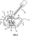
- FIG. 6is a partial assembled view of the ventricular assist device shown in FIGS. 1-5 .
- FIG. 7is a diagrammatic cross-sectional view of the ventricular assist device shown in FIGS. 1-6 accordance with one embodiment of the invention.
- FIG. 1illustrates an implantable blood pump usable as a ventricular assist device (“VAD”) 100 in accordance with one embodiment of the invention.
- the VAD 100comprises a pump 110 having an outer housing 111 that includes and a first or lower housing element 113 and a second or upper housing element 112 .
- the housing elementsare formed from biocompatible rigid materials such as titanium or a hybrid titanium-ceramic.
- the upper housing 112may further comprise an inflow end 114 ( FIG. 2 ) defining an inlet opening 107 .
- FIG. 2In the implanted condition depicted in FIG.
- the inflow end of the pumpis inserted into heart of a mammalian subject such as a human patient, typically into the left ventricle so that the inflow opening is in communication with the interior of the ventricle.
- the VAD 100may also include an apical ring 119 for securing the connection between the outer housing 111 of the pump and the heart.
- the sewing ringtypically is sutured in place on the apex of the heart, and may include a clamp to secure the outer housing 111 to the sewing ring and thus secure the pump in place relative to the heart.
- the VAD 100may also include an outflow conduit 121 extending from the outer housing 111 .
- the outflow conduit 121may comprise a flexible, biocompatible main tubing 122 .
- the main tubing 122may also be encased along a portion of its length by an anti-kinking conduit 123 .
- the anti-kinking conduit 123may be made by plastic interlocking links to prevent kinking.
- the main tubing 122may further be surgically attached to a desired position 124 of the heart or the surrounding area, such as to the ascending aorta as depicted in FIG. 1 .
- the VAD 100may further include a cable 130 , also referred to herein as a driveline.
- Driveline 130typically includes a plurality of electrical conductors 131 .
- the driveline 130electrically connects components of the pump 110 within the outer housing 111 to an external control unit 191 .
- Control unit 191is arranged to supply electrical power to the pump, and to control the operation of the pump. All or part of control unit 191 may be implanted within the body of the subject, or may be external to the subject.
- upper housing element 112 and lower housing element 113define a flow path therein, which extends from the inlet opening 107 to an outflow end 115 a and 115 b cooperatively defined by the housing elements 112 and 113 .
- Permanent magnetsmay be provided within one or both of the housing elements 112 and 113 , along with a set of electromagnet coils, one of which is schematically represented at 109 .
- a permanent magnet stackmay be contained within a center-post 117 on the lower housing element 113 .
- Pump 110further includes a movable element 116 for impelling the blood along the flow path.
- the movable element 116is a wide-bladed impeller, which incorporates permanent magnets (not shown).
- the permanent magnets within impeller 116cooperate with the permanent magnets in the housing elements to keep impeller 116 suspended and out of contact with the housing elements during operation.
- the coil set 109is energized with alternating current, the magnetic interaction between the coil set and the permanent magnets of the impeller spin the impeller around its axis, so that the impeller will drive blood along the flow path.
- the upper 112 and lower 113 housingmay further define a driveline interface 118 a and 118 b for receiving a power connector 127 on the driveline into the pump housing.
- the upper housing 112defines a top portion of the driveline interface 118
- the lower housing 113defines a bottom portion of the driveline interface 118 b.
- the driveline interface 118is provided with appropriate terminals (not shown) for making electrical contact with certain conductors of driveline 130 at power connector 127 . These terminals are electrically connected to the coil set.
- the pumpis provided with a flow sensor carried on or within the housing 111 .
- the first or lower housing element 113is front facing and visible.
- the exterior surface of lower housing element 113has a PCB cavity 361 and a further cavity 162 which accommodates a first platform 163 and a second platform 166 .
- cavity 162is about 0.5 mm in depth.
- the first 163 and second 166 platformshave a height less than or equivalent to the depth of the cavity 166 so that the platforms may be fully accommodated within the cavity 162 .
- FIG. 1the first or lower housing element 113 is front facing and visible.
- the exterior surface of lower housing element 113has a PCB cavity 361 and a further cavity 162 which accommodates a first platform 163 and a second platform 166 .
- cavity 162is about 0.5 mm in depth.
- the first 163 and second 166 platformshave a height less than or equivalent to the depth of the cavity 166 so that the platforms may be fully accommodated within the cavity 162
- platforms 163 and 166overlie a portion 195 of the flow path cooperatively defined by housing elements 112 and 113 .
- This portion of the flow pathis adjacent the outflow end 115 a, 115 b depicted in FIG. 2 .
- the bloodflows in a downstream direction indicated by arrows D in FIG. 7 , generally along a flow path axis 193 .
- the first platform 183defines a first surface 164 facing away from flow path 195 and facing generally upstream (the direction opposite to arrows D) at an angle oblique to the flow path axis 193 , as well as a second surface 165 .
- the second platform 166is disposed downstream from the first platform.
- Second platform 166defines a first surface 167 facing away from the flow path and facing downstream at an angle oblique to the flow path axis 193 , and also defines a second surface 168 .
- the first surface of each platformmay be disposed at an angle of 45 degrees to the axis of the flow path.
- a window 172( FIG. 7 ) forms an interface between the first platform 163 and the interior of the flow path, and another window 172 forms an interface between the second platform and the flow path.
- the windowsare depicted as separate elements from the platforms for clarity of illustration, the windows may be formed integrally with the platforms. Also, the surfaces of the windows bounding the flow path desirably are flush with the surrounding surfaces of housing element 113 .
- the windows and platformsmay be formed integrally with first housing element 113 or may be fixed directly to this housing element.
- the materials of the platforms and windowsdesirably provide a low-impedance path for ultrasound between first surfaces 164 and 187 and the interior of the flow path when the flow path is filled with blood.
- the materials of the platforms and windowsmay have acoustic impedance reasonably close to that of blood so as to minimize reflection of ultrasound at the interface with the blood within the flow path.
- the platforms and windowsmay be formed by casting a biocompatible polymer.
- a first ultrasonic transducer 142is bonded to the first surface 164 of the first platform 163
- a second ultrasonic transducer 144is bonded to the first surface 167 of the second platform 166 .
- the ultrasonic transducersmay be conventional piezoelectric elements.
- the transducersare electrically connected by conductors 145 and 146 to electronic components on a printed circuit board 150 ( FIGS. 5 and 6 ) which is disposed in cavity 161 of housing element 113 .
- the components on the printed circuit boardmay include conventional components for driving one of the transducers (referred to herein as the “driven transducer”) at an ultrasonic frequency, typically in the megahertz range with an electrical signal, and for amplifying electrical signals from the other one of the transducers (referred to herein as the “receiving transducer”).
- the electronic componentsmay also include components for comparing the phase of the electrical signals from the receiving transducer with the phase of the signals applied to drive the driven transducer.
- Printed circuit board 150is connected by conductors 151 to conductors 198 of driveline 130 at a connector 197 engaged in an opening 199 ( FIG. 5 ) communicating with cavity 561 .
- connector 197is separate from the power connector 127 ( FIG. 1 ) engaged with the driveline interface 118 ( FIG. 2 ).
- the conductors associated with connectors 197 and 127extend within the outer sheath of driveline 130 over most of the length of the driveline, and diverge from one another only in the immediate vicinity of the pump.
- Conductors 198 of the drivelinelink the components on PCB 150 with an appropriate circuit in the control unit 191 ( FIG. 1 ).
- a cover schematically indicated at 173( FIG. 7 ) overlies cavities 161 and 162 , and thus forms a part of the housing which cooperates with housing element 113 to enclose the platforms, transducers, printed circuit board and associated conductors.
- Cover 173may be a biocompatible potting material such as an epoxy, or may be a plate fixed to housing element 113 by appropriate fasteners and sealed by an appropriate gasket to prevent entry of body fluids into the cavities 161 and 162 .
- the control unitactuates the components on PCB 550 to drive one of the transducers.
- the control unit and components on PCB 550may cause the first or upstream transducer 143 to emit ultrasonic waves. These waves pass along a path 174 at an oblique angle to the direction of the blood flow (the downstream direction) and impinge on the wall of the flow path defined by the second or upper housing element 112 at a point 175 .
- the ultrasonic wavesare reflected along a further portion of path 174 , also oblique to the downstream direction, back to the receiving transducer, in this case the second or downstream transducer 144 .
- the receiving transducerconverts the ultrasonic waves to electrical signal. Because the path from the driven transducer to the receiving transducer has a component parallel to the direction of flow of the blood, the time of flight of the ultrasonic waves is influenced by the velocity of the blood according to the well-known Doppler effect. This causes the phase of the received ultrasonic waves to vary with the blood velocity, and thus with the flow rate. Because the housing elements 112 and 113 are rigid, the geometry of the system is fixed. As used in this disclosure, the term “rigid” should be understood as meaning that the housing elements do not distort in normal operation of the pump to a degree which would appreciably affect the phase difference between the received and emitted ultrasonic waves. The mathematical relationships used to convert phase difference to flow velocity, and to convert flow velocity to flow rate, are well known. The circuits used to measure phase difference are also well known and accordingly are not further described herein.
- the flow measurementis performed by the ultrasonic sensors mounted in the pump housing, there is no need for a separate flow measurement device mounted along the outflow cannula. Moreover, because the connection between the flow sensor and the control unit is made through conductors of the same driveline used to convey power to the pump, there is no need to implant a separate cable leading to a flow sensor.
- the connectors 197 and 127may be integrated into a single connector, mated to a single driveline interface on the pump housing.
- conductors of the driveline which convey power pump coil systemmay also be used to convey ultrasonic frequency electrical signals to and from the PCB or the transducers in a multiplexing arrangement.
- the PCB 150may also be used to convey power to the electrically driven elements of the pump itself, such as the coil set 109 schematically shown in FIG. 2 .
- the pump depicted in FIGS. 1-7is a radial-flow impeller pump
- the inventioncan be applied in other pumps, such as an axial-flow impeller pump as depicted in the aforementioned U.S. Pat. No. 8,419,609, and in conjunction with pumps such as diaphragm pumps and piston pumps.
- the inventionhas been described with reference to an ultrasonic flow sensor having two ultrasonic transducers, other types of flow sensors may be mounted to the pump housing. For example, flow sensors which measure the rate of heat transfer to the flowing blood from a heated element can be employed.
Landscapes
- Health & Medical Sciences (AREA)
- Heart & Thoracic Surgery (AREA)
- Engineering & Computer Science (AREA)
- Cardiology (AREA)
- Hematology (AREA)
- Mechanical Engineering (AREA)
- Anesthesiology (AREA)
- Biomedical Technology (AREA)
- Life Sciences & Earth Sciences (AREA)
- Animal Behavior & Ethology (AREA)
- General Health & Medical Sciences (AREA)
- Public Health (AREA)
- Veterinary Medicine (AREA)
- Vascular Medicine (AREA)
- External Artificial Organs (AREA)
- Measurement Of The Respiration, Hearing Ability, Form, And Blood Characteristics Of Living Organisms (AREA)
Abstract
Description
Claims (17)
Priority Applications (1)
| Application Number | Priority Date | Filing Date | Title |
|---|---|---|---|
| US15/834,487US10786611B2 (en) | 2012-09-05 | 2017-12-07 | VAD integrated flow sensor |
Applications Claiming Priority (4)
| Application Number | Priority Date | Filing Date | Title |
|---|---|---|---|
| US201261697087P | 2012-09-05 | 2012-09-05 | |
| US14/019,219US9579432B2 (en) | 2012-09-05 | 2013-09-05 | VAD integrated flow sensor |
| US15/406,078US9861730B2 (en) | 2012-09-05 | 2017-01-13 | VAD integrated flow sensor |
| US15/834,487US10786611B2 (en) | 2012-09-05 | 2017-12-07 | VAD integrated flow sensor |
Related Parent Applications (1)
| Application Number | Title | Priority Date | Filing Date |
|---|---|---|---|
| US15/406,078ContinuationUS9861730B2 (en) | 2012-09-05 | 2017-01-13 | VAD integrated flow sensor |
Publications (2)
| Publication Number | Publication Date |
|---|---|
| US20180099077A1 US20180099077A1 (en) | 2018-04-12 |
| US10786611B2true US10786611B2 (en) | 2020-09-29 |
Family
ID=50237599
Family Applications (3)
| Application Number | Title | Priority Date | Filing Date |
|---|---|---|---|
| US14/019,219ActiveUS9579432B2 (en) | 2012-09-05 | 2013-09-05 | VAD integrated flow sensor |
| US15/406,078ActiveUS9861730B2 (en) | 2012-09-05 | 2017-01-13 | VAD integrated flow sensor |
| US15/834,487Active2034-06-23US10786611B2 (en) | 2012-09-05 | 2017-12-07 | VAD integrated flow sensor |
Family Applications Before (2)
| Application Number | Title | Priority Date | Filing Date |
|---|---|---|---|
| US14/019,219ActiveUS9579432B2 (en) | 2012-09-05 | 2013-09-05 | VAD integrated flow sensor |
| US15/406,078ActiveUS9861730B2 (en) | 2012-09-05 | 2017-01-13 | VAD integrated flow sensor |
Country Status (10)
| Country | Link |
|---|---|
| US (3) | US9579432B2 (en) |
| EP (1) | EP2892583B1 (en) |
| JP (1) | JP6268178B2 (en) |
| KR (1) | KR20150052215A (en) |
| CN (1) | CN104768589B (en) |
| AU (1) | AU2013312527A1 (en) |
| CA (1) | CA2884180C (en) |
| IL (1) | IL237526A0 (en) |
| IN (1) | IN2015DN02330A (en) |
| WO (1) | WO2014039673A1 (en) |
Families Citing this family (67)
| Publication number | Priority date | Publication date | Assignee | Title |
|---|---|---|---|---|
| WO2014018969A2 (en) | 2012-07-27 | 2014-01-30 | Thoratec Corporation | Resonant power transfer system and method of estimating system state |
| US10291067B2 (en) | 2012-07-27 | 2019-05-14 | Tc1 Llc | Computer modeling for resonant power transfer systems |
| US9287040B2 (en) | 2012-07-27 | 2016-03-15 | Thoratec Corporation | Self-tuning resonant power transfer systems |
| WO2014018973A1 (en) | 2012-07-27 | 2014-01-30 | Thoratec Corporation | Resonant power transmission coils and systems |
| WO2014018974A1 (en) | 2012-07-27 | 2014-01-30 | Thoratec Corporation | Magnetic power transmission utilizing phased transmitter coil arrays and phased receiver coil arrays |
| EP4257174A3 (en) | 2012-07-27 | 2023-12-27 | Tc1 Llc | Thermal management for implantable wireless power transfer systems |
| US10383990B2 (en) | 2012-07-27 | 2019-08-20 | Tc1 Llc | Variable capacitor for resonant power transfer systems |
| WO2014018971A1 (en) | 2012-07-27 | 2014-01-30 | Thoratec Corporation | Resonant power transfer systems with protective algorithm |
| EP2984731B8 (en) | 2013-03-15 | 2019-06-26 | Tc1 Llc | Malleable tets coil with improved anatomical fit |
| WO2014145664A1 (en) | 2013-03-15 | 2014-09-18 | Thoratec Corporation | Integrated implantable tets housing including fins and coil loops |
| EP3069358B1 (en) | 2013-11-11 | 2019-06-12 | Tc1 Llc | Hinged resonant power transfer coil |
| EP3072210B1 (en) | 2013-11-11 | 2023-12-20 | Tc1 Llc | Resonant power transfer systems with communications |
| US10695476B2 (en) | 2013-11-11 | 2020-06-30 | Tc1 Llc | Resonant power transfer systems with communications |
| WO2015134871A1 (en) | 2014-03-06 | 2015-09-11 | Thoratec Corporation | Electrical connectors for implantable devices |
| EP2946860A1 (en)* | 2014-05-20 | 2015-11-25 | HILTI Aktiengesellschaft | Suction device |
| EP3826104B1 (en) | 2014-09-22 | 2023-05-03 | Tc1 Llc | Antenna designs for communication between a wirelessly powered implant to an external device outside the body |
| WO2016057525A1 (en) | 2014-10-06 | 2016-04-14 | Thoratec Corporation | Multiaxial connector for implantable devices |
| EP3135327A1 (en)* | 2015-08-31 | 2017-03-01 | Berlin Heart GmbH | Pump for supplying liquids and method for determining a flow rate |
| US10148126B2 (en) | 2015-08-31 | 2018-12-04 | Tc1 Llc | Wireless energy transfer system and wearables |
| WO2017062552A1 (en) | 2015-10-07 | 2017-04-13 | Tc1 Llc | Resonant power transfer systems having efficiency optimization based on receiver impedance |
| DE102016209871A1 (en) | 2016-06-06 | 2017-12-07 | Robert Bosch Gmbh | Punching device and method for punching a lumen and implanting an implant device |
| WO2018017563A1 (en) | 2016-07-19 | 2018-01-25 | Heartware, Inc. | Ventricular assist devices and integrated sensors thereof |
| WO2018048800A1 (en)* | 2016-09-06 | 2018-03-15 | Heartware, Inc. | Integrated sensors for intraventricular vad |
| EP4084271A1 (en) | 2016-09-21 | 2022-11-02 | Tc1 Llc | Systems and methods for locating implanted wireless power transmission devices |
| EP3515524B1 (en)* | 2016-09-23 | 2020-12-30 | Heartware, Inc. | Blood pump with sensors on housing surface |
| WO2018136592A2 (en) | 2017-01-18 | 2018-07-26 | Tc1 Llc | Systems and methods for transcutaneous power transfer using microneedles |
| US10780209B2 (en) | 2017-03-29 | 2020-09-22 | Tc1 Llc | Adjusting pump protocol based on irregular heart rhythm |
| US11065436B2 (en) | 2017-03-29 | 2021-07-20 | Tc1 Llc | Communication methods and architecture for heart treatment systems |
| WO2018183568A1 (en) | 2017-03-29 | 2018-10-04 | Tc1 Llc | Pressure sensing ventricular assist devices and methods of use |
| EP3615103B1 (en) | 2017-04-25 | 2021-03-24 | Heartware, Inc. | Anti-thrombus surface potential ceramic element |
| WO2019135890A1 (en) | 2018-01-04 | 2019-07-11 | Tc1 Llc | Systems and methods for elastic wireless power transmission devices |
| DE102018201030B4 (en) | 2018-01-24 | 2025-10-16 | Kardion Gmbh | Magnetic dome element with magnetic bearing function |
| EP4461341A3 (en) | 2018-03-15 | 2025-01-15 | Tc1 Llc | Systems for preventing right heart failure |
| US11167123B2 (en) | 2018-03-19 | 2021-11-09 | Tc1 Llc | Coordinated ventricular assist and cardiac rhythm management devices and methods |
| DE102018206725A1 (en) | 2018-05-02 | 2019-11-07 | Kardion Gmbh | Receiving unit, transmitting unit, energy transmission system and method for wireless energy transmission |
| DE102018206724A1 (en) | 2018-05-02 | 2019-11-07 | Kardion Gmbh | Energy transmission system and method for wireless energy transmission |
| DE102018206754A1 (en) | 2018-05-02 | 2019-11-07 | Kardion Gmbh | Method and device for determining the temperature at a surface and use of the method |
| DE102018206731A1 (en) | 2018-05-02 | 2019-11-07 | Kardion Gmbh | Device for inductive energy transmission in a human body and use of the device |
| DE102018206750A1 (en) | 2018-05-02 | 2019-11-07 | Kardion Gmbh | Device for inductive energy transfer into a human body and its use |
| DE102018207611A1 (en) | 2018-05-16 | 2019-11-21 | Kardion Gmbh | Rotor bearing system |
| DE102018207575A1 (en) | 2018-05-16 | 2019-11-21 | Kardion Gmbh | Magnetic face turning coupling for the transmission of torques |
| DE102018208550A1 (en) | 2018-05-30 | 2019-12-05 | Kardion Gmbh | A lead device for directing blood flow to a cardiac assist system, cardiac assist system, and method of making a lead device |
| DE102018208555A1 (en) | 2018-05-30 | 2019-12-05 | Kardion Gmbh | Apparatus for anchoring a cardiac assist system in a blood vessel, method of operation, and method of making a device and cardiac assist system |
| DE102018208541A1 (en) | 2018-05-30 | 2019-12-05 | Kardion Gmbh | Axial pump for a cardiac assist system and method of making an axial pump for a cardiac assist system |
| DE102018208538A1 (en) | 2018-05-30 | 2019-12-05 | Kardion Gmbh | Intravascular blood pump and process for the production of electrical conductors |
| DE102018208539A1 (en) | 2018-05-30 | 2019-12-05 | Kardion Gmbh | A motor housing module for sealing an engine compartment of a motor of a cardiac assist system and cardiac assistance system and method for mounting a cardiac assist system |
| DE102018208862A1 (en) | 2018-06-06 | 2019-12-12 | Kardion Gmbh | Implantable vascular support system |
| DE102018208870A1 (en)* | 2018-06-06 | 2019-12-12 | Kardion Gmbh | A method of determining a fluid volume flow through an implanted vascular support system |
| DE102018208899A1 (en) | 2018-06-06 | 2019-12-12 | Kardion Gmbh | A method for determining the speed of sound in a fluid in the region of an implanted vascular support system |
| DE102018208879A1 (en) | 2018-06-06 | 2020-01-30 | Kardion Gmbh | Method for determining a total fluid volume flow in the area of an implanted, vascular support system |
| DE102018208913A1 (en) | 2018-06-06 | 2019-12-12 | Kardion Gmbh | A method of operating an implanted ventricular assist device |
| DE102018208936A1 (en) | 2018-06-06 | 2019-12-12 | Kardion Gmbh | Determining device and method for determining a viscosity of a fluid |
| DE102018208945A1 (en) | 2018-06-06 | 2019-12-12 | Kardion Gmbh | An analysis device and method for analyzing a viscosity of a fluid |
| DE102018208933A1 (en)* | 2018-06-06 | 2019-12-12 | Kardion Gmbh | A method of determining a flow rate of fluid flowing through an implanted vascular support system |
| DE102018208931A1 (en) | 2018-06-06 | 2019-12-12 | Kardion Gmbh | Apparatus for determining cardiac output for a cardiac assist system, cardiac assistive system and method for determining cardiac output |
| DE102018208929A1 (en) | 2018-06-06 | 2019-12-12 | Kardion Gmbh | A method of determining a flow rate of fluid flowing through an implanted vascular support system |
| DE102018210058A1 (en) | 2018-06-21 | 2019-12-24 | Kardion Gmbh | Stator blade device for guiding the flow of a fluid flowing out of an outlet opening of a heart support system, heart support system with stator blade device, method for operating a stator blade device and manufacturing method |
| DE102018210076A1 (en) | 2018-06-21 | 2019-12-24 | Kardion Gmbh | Method and device for detecting a state of wear of a cardiac support system, method and device for operating a cardiac support system and cardiac support system |
| DE102018211327A1 (en) | 2018-07-10 | 2020-01-16 | Kardion Gmbh | Impeller for an implantable vascular support system |
| US11241570B2 (en) | 2018-07-17 | 2022-02-08 | Tc1 Llc | Systems and methods for inertial sensing for VAD diagnostics and closed loop control |
| DE102018212153A1 (en) | 2018-07-20 | 2020-01-23 | Kardion Gmbh | Inlet line for a pump unit of a cardiac support system, cardiac support system and method for producing an inlet line for a pump unit of a cardiac support system |
| CN112654389A (en) | 2018-08-07 | 2021-04-13 | 开迪恩有限公司 | Bearing device for a cardiac support system and method for flushing an intermediate space in a bearing device for a cardiac support system |
| DE102020102474A1 (en) | 2020-01-31 | 2021-08-05 | Kardion Gmbh | Pump for conveying a fluid and method for manufacturing a pump |
| EP3984589B1 (en)* | 2020-04-07 | 2023-08-23 | Magenta Medical Ltd. | Magnetic phase sensing |
| US11699551B2 (en) | 2020-11-05 | 2023-07-11 | Kardion Gmbh | Device for inductive energy transmission in a human body and use of the device |
| CN114504728A (en)* | 2020-11-17 | 2022-05-17 | 苏州恒瑞宏远医疗科技有限公司 | A sensor for cardiac blood pump and cardiac blood pump |
| US20230007971A1 (en)* | 2021-07-08 | 2023-01-12 | Heartware, Inc. | Dual stator pump split connnector |
Citations (16)
| Publication number | Priority date | Publication date | Assignee | Title |
|---|---|---|---|---|
| US4068521A (en)* | 1976-07-22 | 1978-01-17 | Renal Systems, Inc. | Ultrasonic air and blood foam detector |
| US4752690A (en)* | 1986-08-11 | 1988-06-21 | Coulter Electronics, Inc. | Method and apparatus for detecting incongruities, such as air bubbles, in fluid material |
| US5078148A (en) | 1988-10-05 | 1992-01-07 | Cardiometrics, Inc. | Apparatus and method for continuously measuring volumetric blood flow using multiple transducers and catheter for use therewith |
| JPH0568709A (en) | 1991-09-13 | 1993-03-23 | Terumo Corp | Medical liquid supply device |
| EP1046403A1 (en) | 1997-12-27 | 2000-10-25 | JMS Co., Ltd. | Blood circulation auxiliary device using continuous blood flow pump and diagnosis device for blood circulation state in organism |
| US6190319B1 (en) | 1999-06-21 | 2001-02-20 | International Business Machines Corporation | Self calibrating linear position sensor |
| US20050107658A1 (en)* | 2003-11-19 | 2005-05-19 | Transoma Medical, Inc. | Feedback control of ventricular assist devices |
| US20080021325A1 (en)* | 2006-06-12 | 2008-01-24 | Drost Cornelis J | System and method of perivascular pressure and flow measurement |
| US20080133006A1 (en)* | 2006-10-27 | 2008-06-05 | Ventrassist Pty Ltd | Blood Pump With An Ultrasonic Transducer |
| US7575423B2 (en) | 1996-02-20 | 2009-08-18 | Heartware, Inc. | Sealless rotary blood pump |
| US20100222634A1 (en) | 2009-02-27 | 2010-09-02 | Thoratec Corporation | Blood flow meter |
| US20100240944A1 (en) | 2009-03-23 | 2010-09-23 | Michael Maschke | Blood pump, medical apparatus having a blood pump and method for assisting the positioning of a blood pump |
| US7976271B2 (en) | 2006-01-13 | 2011-07-12 | Heartware, Inc. | Stabilizing drive for contactless rotary blood pump impeller |
| US20110178361A1 (en) | 2010-01-19 | 2011-07-21 | Barry Yomtov | Physiologically responsive vad |
| US8007254B2 (en) | 2004-12-03 | 2011-08-30 | Heartware, Inc. | Axial flow pump with multi-grooved rotor |
| US20110257579A1 (en) | 2010-04-20 | 2011-10-20 | Sorin Group Italia S.r.I. | Blood reservoir with ultrasonic volume sensor |
- 2013
- 2013-09-05KRKR1020157008435Apatent/KR20150052215A/ennot_activeWithdrawn
- 2013-09-05CACA2884180Apatent/CA2884180C/ennot_activeExpired - Fee Related
- 2013-09-05ININ2330DEN2015patent/IN2015DN02330A/enunknown
- 2013-09-05USUS14/019,219patent/US9579432B2/enactiveActive
- 2013-09-05AUAU2013312527Apatent/AU2013312527A1/ennot_activeAbandoned
- 2013-09-05JPJP2015531182Apatent/JP6268178B2/ennot_activeExpired - Fee Related
- 2013-09-05EPEP13835446.9Apatent/EP2892583B1/enactiveActive
- 2013-09-05WOPCT/US2013/058253patent/WO2014039673A1/enactiveApplication Filing
- 2013-09-05CNCN201380057534.1Apatent/CN104768589B/enactiveActive
- 2015
- 2015-03-03ILIL237526Apatent/IL237526A0/enunknown
- 2017
- 2017-01-13USUS15/406,078patent/US9861730B2/enactiveActive
- 2017-12-07USUS15/834,487patent/US10786611B2/enactiveActive
Patent Citations (18)
| Publication number | Priority date | Publication date | Assignee | Title |
|---|---|---|---|---|
| US4068521A (en)* | 1976-07-22 | 1978-01-17 | Renal Systems, Inc. | Ultrasonic air and blood foam detector |
| US4752690A (en)* | 1986-08-11 | 1988-06-21 | Coulter Electronics, Inc. | Method and apparatus for detecting incongruities, such as air bubbles, in fluid material |
| US5078148A (en) | 1988-10-05 | 1992-01-07 | Cardiometrics, Inc. | Apparatus and method for continuously measuring volumetric blood flow using multiple transducers and catheter for use therewith |
| JPH0568709A (en) | 1991-09-13 | 1993-03-23 | Terumo Corp | Medical liquid supply device |
| US7575423B2 (en) | 1996-02-20 | 2009-08-18 | Heartware, Inc. | Sealless rotary blood pump |
| EP1046403A1 (en) | 1997-12-27 | 2000-10-25 | JMS Co., Ltd. | Blood circulation auxiliary device using continuous blood flow pump and diagnosis device for blood circulation state in organism |
| US6190319B1 (en) | 1999-06-21 | 2001-02-20 | International Business Machines Corporation | Self calibrating linear position sensor |
| US20050107658A1 (en)* | 2003-11-19 | 2005-05-19 | Transoma Medical, Inc. | Feedback control of ventricular assist devices |
| US8007254B2 (en) | 2004-12-03 | 2011-08-30 | Heartware, Inc. | Axial flow pump with multi-grooved rotor |
| US8419609B2 (en) | 2005-10-05 | 2013-04-16 | Heartware Inc. | Impeller for a rotary ventricular assist device |
| US7976271B2 (en) | 2006-01-13 | 2011-07-12 | Heartware, Inc. | Stabilizing drive for contactless rotary blood pump impeller |
| US20080021325A1 (en)* | 2006-06-12 | 2008-01-24 | Drost Cornelis J | System and method of perivascular pressure and flow measurement |
| US20080133006A1 (en)* | 2006-10-27 | 2008-06-05 | Ventrassist Pty Ltd | Blood Pump With An Ultrasonic Transducer |
| US20100222634A1 (en) | 2009-02-27 | 2010-09-02 | Thoratec Corporation | Blood flow meter |
| US8449444B2 (en) | 2009-02-27 | 2013-05-28 | Thoratec Corporation | Blood flow meter |
| US20100240944A1 (en) | 2009-03-23 | 2010-09-23 | Michael Maschke | Blood pump, medical apparatus having a blood pump and method for assisting the positioning of a blood pump |
| US20110178361A1 (en) | 2010-01-19 | 2011-07-21 | Barry Yomtov | Physiologically responsive vad |
| US20110257579A1 (en) | 2010-04-20 | 2011-10-20 | Sorin Group Italia S.r.I. | Blood reservoir with ultrasonic volume sensor |
Non-Patent Citations (5)
| Title |
|---|
| Chinese Office Action and Search Report for Application No. 201380057534.1 dated Mar. 3, 2016. |
| Extended European Search Report for Application No. 13835446.9 dated May 4, 2016. |
| International Search Report issued by the International Searching Authority (ISA/US) dated Dec. 19, 2013 in connection with International Application No. PCT/US2013/058253. |
| Japan Office Action dated Jun. 27, 2017, corresponding Patent Application No. 2015-531182. |
| Written Opinion of the International Searching Authority issued by the International Searching Authority (ISA/US) dated Dec. 19, 2013 in connection with International Application No. PCT/US2013/058253. |
Also Published As
| Publication number | Publication date |
|---|---|
| JP6268178B2 (en) | 2018-01-24 |
| CN104768589A (en) | 2015-07-08 |
| US20180099077A1 (en) | 2018-04-12 |
| US9579432B2 (en) | 2017-02-28 |
| WO2014039673A1 (en) | 2014-03-13 |
| EP2892583A1 (en) | 2015-07-15 |
| EP2892583B1 (en) | 2023-01-25 |
| EP2892583A4 (en) | 2016-06-01 |
| CA2884180C (en) | 2017-08-22 |
| KR20150052215A (en) | 2015-05-13 |
| US9861730B2 (en) | 2018-01-09 |
| US20140100414A1 (en) | 2014-04-10 |
| AU2013312527A1 (en) | 2015-04-09 |
| IL237526A0 (en) | 2015-04-30 |
| CN104768589B (en) | 2017-04-19 |
| CA2884180A1 (en) | 2014-03-13 |
| US20170157308A1 (en) | 2017-06-08 |
| JP2015527172A (en) | 2015-09-17 |
| IN2015DN02330A (en) | 2015-08-28 |
Similar Documents
| Publication | Publication Date | Title |
|---|---|---|
| US10786611B2 (en) | VAD integrated flow sensor | |
| CN109475671B (en) | Ventricular assist device and its integrated sensor | |
| EP3509662B1 (en) | Integrated sensors for intraventricular vad | |
| US8876685B2 (en) | Blood pump with an ultrasound transducer | |
| EP2988795B1 (en) | Biomedical apparatus for pumping blood of a human or an animal patient through a secondary intra- or extracorporeal blood circuit | |
| US8657875B2 (en) | Method and apparatus for pumping blood | |
| JP6055083B2 (en) | Intravascular rotary blood pump | |
| US20180311426A1 (en) | Ventricular assist device with pulse augmentation and automatic regurgitant flow shutoff | |
| JP2000512191A (en) | Intracardiac blood pump | |
| US20210178038A1 (en) | Detecting pump suction, pump thrombus, and other adverse vad motor events | |
| CN118178853A (en) | Blood pump assembly, blood pump and fixing method of sensor device | |
| AU2013200786A1 (en) | Blood Pump With An Ultrasonic Transducer |
Legal Events
| Date | Code | Title | Description |
|---|---|---|---|
| AS | Assignment | Owner name:HEARTWARE, INC., FLORIDA Free format text:ASSIGNMENT OF ASSIGNORS INTEREST;ASSIGNORS:TAMEZ, DAN;VOSKOBOYNIKOV, NEIL;REEL/FRAME:044328/0921 Effective date:20130917 | |
| FEPP | Fee payment procedure | Free format text:ENTITY STATUS SET TO UNDISCOUNTED (ORIGINAL EVENT CODE: BIG.); ENTITY STATUS OF PATENT OWNER: LARGE ENTITY | |
| STPP | Information on status: patent application and granting procedure in general | Free format text:DOCKETED NEW CASE - READY FOR EXAMINATION | |
| STPP | Information on status: patent application and granting procedure in general | Free format text:NON FINAL ACTION MAILED | |
| STPP | Information on status: patent application and granting procedure in general | Free format text:RESPONSE TO NON-FINAL OFFICE ACTION ENTERED AND FORWARDED TO EXAMINER | |
| STPP | Information on status: patent application and granting procedure in general | Free format text:NON FINAL ACTION MAILED | |
| STPP | Information on status: patent application and granting procedure in general | Free format text:FINAL REJECTION MAILED | |
| STPP | Information on status: patent application and granting procedure in general | Free format text:DOCKETED NEW CASE - READY FOR EXAMINATION | |
| STPP | Information on status: patent application and granting procedure in general | Free format text:NOTICE OF ALLOWANCE MAILED -- APPLICATION RECEIVED IN OFFICE OF PUBLICATIONS | |
| STCF | Information on status: patent grant | Free format text:PATENTED CASE | |
| MAFP | Maintenance fee payment | Free format text:PAYMENT OF MAINTENANCE FEE, 4TH YEAR, LARGE ENTITY (ORIGINAL EVENT CODE: M1551); ENTITY STATUS OF PATENT OWNER: LARGE ENTITY Year of fee payment:4 | |
| AS | Assignment | Owner name:BOSTON SCIENTIFIC SCIMED, INC., MINNESOTA Free format text:ASSIGNMENT OF ASSIGNORS INTEREST;ASSIGNOR:HEARTWARE, INC.;REEL/FRAME:069433/0581 Effective date:20241108 |