US10786608B2 - Dynamic negative-pressure therapy with instillation - Google Patents
Dynamic negative-pressure therapy with instillationDownload PDFInfo
- Publication number
- US10786608B2 US10786608B2US15/510,185US201515510185AUS10786608B2US 10786608 B2US10786608 B2US 10786608B2US 201515510185 AUS201515510185 AUS 201515510185AUS 10786608 B2US10786608 B2US 10786608B2
- Authority
- US
- United States
- Prior art keywords
- chamber
- negative
- pressure
- check valve
- fluidly coupled
- Prior art date
- Legal status (The legal status is an assumption and is not a legal conclusion. Google has not performed a legal analysis and makes no representation as to the accuracy of the status listed.)
- Active, expires
Links
- 238000002560therapeutic procedureMethods0.000titledescription60
- 238000013022ventingMethods0.000claimsabstractdescription22
- 238000000034methodMethods0.000claimsabstractdescription14
- 239000012530fluidSubstances0.000claimsdescription60
- 230000002209hydrophobic effectEffects0.000claimsdescription19
- 230000008878couplingEffects0.000claimsdescription13
- 238000010168coupling processMethods0.000claimsdescription13
- 238000005859coupling reactionMethods0.000claimsdescription13
- 238000000638solvent extractionMethods0.000claims3
- 239000000243solutionSubstances0.000description81
- 210000001519tissueAnatomy0.000description80
- 206010052428WoundDiseases0.000description15
- 208000027418Wounds and injuryDiseases0.000description15
- 239000000463materialSubstances0.000description14
- 230000000694effectsEffects0.000description13
- 230000014759maintenance of locationEffects0.000description12
- 239000006260foamSubstances0.000description11
- 239000012528membraneSubstances0.000description10
- 230000001225therapeutic effectEffects0.000description10
- 210000000416exudates and transudateAnatomy0.000description8
- 238000005192partitionMethods0.000description7
- 230000008901benefitEffects0.000description6
- 238000010586diagramMethods0.000description6
- 239000004020conductorSubstances0.000description5
- 230000003247decreasing effectEffects0.000description5
- 239000011148porous materialSubstances0.000description5
- 230000000699topical effectEffects0.000description5
- 230000010261cell growthEffects0.000description4
- 230000007423decreaseEffects0.000description4
- 229920001971elastomerPolymers0.000description4
- 230000037361pathwayEffects0.000description4
- 230000002093peripheral effectEffects0.000description4
- 229920000954PolyglycolidePolymers0.000description3
- 230000004888barrier functionEffects0.000description3
- 238000004891communicationMethods0.000description3
- 239000006261foam materialSubstances0.000description3
- 239000007788liquidSubstances0.000description3
- 239000000203mixtureSubstances0.000description3
- 239000004633polyglycolic acidSubstances0.000description3
- 230000008569processEffects0.000description3
- 239000000126substanceSubstances0.000description3
- 229920005830Polyurethane FoamPolymers0.000description2
- 208000025865UlcerDiseases0.000description2
- 239000000853adhesiveSubstances0.000description2
- 230000001070adhesive effectEffects0.000description2
- 230000001580bacterial effectEffects0.000description2
- 238000012412chemical couplingMethods0.000description2
- 239000000356contaminantSubstances0.000description2
- 238000011109contaminationMethods0.000description2
- 238000011161developmentMethods0.000description2
- 239000000806elastomerSubstances0.000description2
- 210000002615epidermisAnatomy0.000description2
- 239000000499gelSubstances0.000description2
- 230000012010growthEffects0.000description2
- WQYVRQLZKVEZGA-UHFFFAOYSA-NhypochloriteChemical compoundCl[O-]WQYVRQLZKVEZGA-UHFFFAOYSA-N0.000description2
- 208000014674injuryDiseases0.000description2
- 239000006193liquid solutionSubstances0.000description2
- 239000000314lubricantSubstances0.000description2
- 230000007246mechanismEffects0.000description2
- 239000004626polylactic acidSubstances0.000description2
- 239000011496polyurethane foamSubstances0.000description2
- 238000007789sealingMethods0.000description2
- SQGYOTSLMSWVJD-UHFFFAOYSA-Nsilver(1+) nitrateChemical compound[Ag+].[O-]N(=O)=OSQGYOTSLMSWVJD-UHFFFAOYSA-N0.000description2
- 230000008733traumaEffects0.000description2
- 231100000397ulcerToxicity0.000description2
- 229940123208BiguanideDrugs0.000description1
- 235000014653Carica parvifloraNutrition0.000description1
- 241000243321CnidariaSpecies0.000description1
- 102000008186CollagenHuman genes0.000description1
- 108010035532CollagenProteins0.000description1
- 206010063560Excessive granulation tissueDiseases0.000description1
- 239000004721Polyphenylene oxideSubstances0.000description1
- 239000004372Polyvinyl alcoholSubstances0.000description1
- 239000004820Pressure-sensitive adhesiveSubstances0.000description1
- 229920001247Reticulated foamPolymers0.000description1
- NINIDFKCEFEMDL-UHFFFAOYSA-NSulfurChemical compound[S]NINIDFKCEFEMDL-UHFFFAOYSA-N0.000description1
- 239000003522acrylic cementSubstances0.000description1
- 230000001154acute effectEffects0.000description1
- 210000000577adipose tissueAnatomy0.000description1
- 230000009286beneficial effectEffects0.000description1
- 150000004283biguanidesChemical class0.000description1
- 230000015572biosynthetic processEffects0.000description1
- 230000017531blood circulationEffects0.000description1
- 210000000988bone and boneAnatomy0.000description1
- 229910000389calcium phosphateInorganic materials0.000description1
- 239000001506calcium phosphateSubstances0.000description1
- 235000011010calcium phosphatesNutrition0.000description1
- 150000004649carbonic acid derivativesChemical class0.000description1
- 210000000845cartilageAnatomy0.000description1
- 125000002091cationic groupChemical group0.000description1
- 230000001413cellular effectEffects0.000description1
- 230000001684chronic effectEffects0.000description1
- 239000011248coating agentSubstances0.000description1
- 238000000576coating methodMethods0.000description1
- 229920001436collagenPolymers0.000description1
- 210000002808connective tissueAnatomy0.000description1
- 230000007547defectEffects0.000description1
- 230000002950deficientEffects0.000description1
- 206010012601diabetes mellitusDiseases0.000description1
- 230000002500effect on skinEffects0.000description1
- 210000000981epitheliumAnatomy0.000description1
- 210000001126granulation tissueAnatomy0.000description1
- 230000035876healingEffects0.000description1
- 239000000416hydrocolloidSubstances0.000description1
- 239000000017hydrogelSubstances0.000description1
- 230000002706hydrostatic effectEffects0.000description1
- 125000002887hydroxy groupChemical group[H]O*0.000description1
- 208000015181infectious diseaseDiseases0.000description1
- 230000002458infectious effectEffects0.000description1
- 230000001788irregularEffects0.000description1
- 230000002262irrigationEffects0.000description1
- 238000003973irrigationMethods0.000description1
- 239000000644isotonic solutionSubstances0.000description1
- 210000003041ligamentAnatomy0.000description1
- 230000005012migrationEffects0.000description1
- 238000013508migrationMethods0.000description1
- 238000012986modificationMethods0.000description1
- 230000004048modificationEffects0.000description1
- 210000003205muscleAnatomy0.000description1
- 238000009581negative-pressure wound therapyMethods0.000description1
- 230000001537neural effectEffects0.000description1
- 206010033675panniculitisDiseases0.000description1
- 239000006072pasteSubstances0.000description1
- 229940021222peritoneal dialysis isotonic solutionDrugs0.000description1
- 230000035699permeabilityEffects0.000description1
- 229920003023plasticPolymers0.000description1
- 239000004033plasticSubstances0.000description1
- 229920000747poly(lactic acid)Polymers0.000description1
- 239000004417polycarbonateSubstances0.000description1
- 229920000515polycarbonatePolymers0.000description1
- 229920000570polyetherPolymers0.000description1
- 229920000642polymerPolymers0.000description1
- 229920001296polysiloxanePolymers0.000description1
- 229920006264polyurethane filmPolymers0.000description1
- 229920002451polyvinyl alcoholPolymers0.000description1
- 238000012545processingMethods0.000description1
- 229910001961silver nitrateInorganic materials0.000description1
- 210000004304subcutaneous tissueAnatomy0.000description1
- 239000011593sulfurSubstances0.000description1
- 229910052717sulfurInorganic materials0.000description1
- 238000001356surgical procedureMethods0.000description1
- 210000002435tendonAnatomy0.000description1
- 230000008467tissue growthEffects0.000description1
- 230000000472traumatic effectEffects0.000description1
- QORWJWZARLRLPR-UHFFFAOYSA-Htricalcium bis(phosphate)Chemical compound[Ca+2].[Ca+2].[Ca+2].[O-]P([O-])([O-])=O.[O-]P([O-])([O-])=OQORWJWZARLRLPR-UHFFFAOYSA-H0.000description1
- 238000011144upstream manufacturingMethods0.000description1
- 230000002792vascularEffects0.000description1
- 201000002282venous insufficiencyDiseases0.000description1
- 239000002699waste materialSubstances0.000description1
- XLYOFNOQVPJJNP-UHFFFAOYSA-NwaterChemical compoundOXLYOFNOQVPJJNP-UHFFFAOYSA-N0.000description1
- 230000029663wound healingEffects0.000description1
Images


Classifications
- A61M1/0084—
- A—HUMAN NECESSITIES
- A61—MEDICAL OR VETERINARY SCIENCE; HYGIENE
- A61M—DEVICES FOR INTRODUCING MEDIA INTO, OR ONTO, THE BODY; DEVICES FOR TRANSDUCING BODY MEDIA OR FOR TAKING MEDIA FROM THE BODY; DEVICES FOR PRODUCING OR ENDING SLEEP OR STUPOR
- A61M1/00—Suction or pumping devices for medical purposes; Devices for carrying-off, for treatment of, or for carrying-over, body-liquids; Drainage systems
- A61M1/84—Drainage tubes; Aspiration tips
- A61M1/85—Drainage tubes; Aspiration tips with gas or fluid supply means, e.g. for supplying rinsing fluids or anticoagulants
- A61F13/00017—
- A61F13/00042—
- A61F13/00068—
- A—HUMAN NECESSITIES
- A61—MEDICAL OR VETERINARY SCIENCE; HYGIENE
- A61F—FILTERS IMPLANTABLE INTO BLOOD VESSELS; PROSTHESES; DEVICES PROVIDING PATENCY TO, OR PREVENTING COLLAPSING OF, TUBULAR STRUCTURES OF THE BODY, e.g. STENTS; ORTHOPAEDIC, NURSING OR CONTRACEPTIVE DEVICES; FOMENTATION; TREATMENT OR PROTECTION OF EYES OR EARS; BANDAGES, DRESSINGS OR ABSORBENT PADS; FIRST-AID KITS
- A61F13/00—Bandages or dressings; Absorbent pads
- A61F13/01—Non-adhesive bandages or dressings
- A61F13/01008—Non-adhesive bandages or dressings characterised by the material
- A61F13/01017—Non-adhesive bandages or dressings characterised by the material synthetic, e.g. polymer based
- A—HUMAN NECESSITIES
- A61—MEDICAL OR VETERINARY SCIENCE; HYGIENE
- A61F—FILTERS IMPLANTABLE INTO BLOOD VESSELS; PROSTHESES; DEVICES PROVIDING PATENCY TO, OR PREVENTING COLLAPSING OF, TUBULAR STRUCTURES OF THE BODY, e.g. STENTS; ORTHOPAEDIC, NURSING OR CONTRACEPTIVE DEVICES; FOMENTATION; TREATMENT OR PROTECTION OF EYES OR EARS; BANDAGES, DRESSINGS OR ABSORBENT PADS; FIRST-AID KITS
- A61F13/00—Bandages or dressings; Absorbent pads
- A61F13/01—Non-adhesive bandages or dressings
- A61F13/01034—Non-adhesive bandages or dressings characterised by a property
- A61F13/01042—Absorbency
- A—HUMAN NECESSITIES
- A61—MEDICAL OR VETERINARY SCIENCE; HYGIENE
- A61F—FILTERS IMPLANTABLE INTO BLOOD VESSELS; PROSTHESES; DEVICES PROVIDING PATENCY TO, OR PREVENTING COLLAPSING OF, TUBULAR STRUCTURES OF THE BODY, e.g. STENTS; ORTHOPAEDIC, NURSING OR CONTRACEPTIVE DEVICES; FOMENTATION; TREATMENT OR PROTECTION OF EYES OR EARS; BANDAGES, DRESSINGS OR ABSORBENT PADS; FIRST-AID KITS
- A61F13/00—Bandages or dressings; Absorbent pads
- A61F13/05—Bandages or dressings; Absorbent pads specially adapted for use with sub-pressure or over-pressure therapy, wound drainage or wound irrigation, e.g. for use with negative-pressure wound therapy [NPWT]
- A61M1/0088—
- A61M1/0092—
- A—HUMAN NECESSITIES
- A61—MEDICAL OR VETERINARY SCIENCE; HYGIENE
- A61M—DEVICES FOR INTRODUCING MEDIA INTO, OR ONTO, THE BODY; DEVICES FOR TRANSDUCING BODY MEDIA OR FOR TAKING MEDIA FROM THE BODY; DEVICES FOR PRODUCING OR ENDING SLEEP OR STUPOR
- A61M1/00—Suction or pumping devices for medical purposes; Devices for carrying-off, for treatment of, or for carrying-over, body-liquids; Drainage systems
- A61M1/90—Negative pressure wound therapy devices, i.e. devices for applying suction to a wound to promote healing, e.g. including a vacuum dressing
- A61M1/92—Negative pressure wound therapy devices, i.e. devices for applying suction to a wound to promote healing, e.g. including a vacuum dressing with liquid supply means
- A—HUMAN NECESSITIES
- A61—MEDICAL OR VETERINARY SCIENCE; HYGIENE
- A61M—DEVICES FOR INTRODUCING MEDIA INTO, OR ONTO, THE BODY; DEVICES FOR TRANSDUCING BODY MEDIA OR FOR TAKING MEDIA FROM THE BODY; DEVICES FOR PRODUCING OR ENDING SLEEP OR STUPOR
- A61M1/00—Suction or pumping devices for medical purposes; Devices for carrying-off, for treatment of, or for carrying-over, body-liquids; Drainage systems
- A61M1/90—Negative pressure wound therapy devices, i.e. devices for applying suction to a wound to promote healing, e.g. including a vacuum dressing
- A61M1/96—Suction control thereof
- A61M1/964—Suction control thereof having venting means on or near the dressing
- A—HUMAN NECESSITIES
- A61—MEDICAL OR VETERINARY SCIENCE; HYGIENE
- A61M—DEVICES FOR INTRODUCING MEDIA INTO, OR ONTO, THE BODY; DEVICES FOR TRANSDUCING BODY MEDIA OR FOR TAKING MEDIA FROM THE BODY; DEVICES FOR PRODUCING OR ENDING SLEEP OR STUPOR
- A61M3/00—Medical syringes, e.g. enemata; Irrigators
- A61M3/02—Enemata; Irrigators
- A61M3/0204—Physical characteristics of the irrigation fluid, e.g. conductivity or turbidity
- A61M3/0208—Physical characteristics of the irrigation fluid, e.g. conductivity or turbidity before use
- A—HUMAN NECESSITIES
- A61—MEDICAL OR VETERINARY SCIENCE; HYGIENE
- A61M—DEVICES FOR INTRODUCING MEDIA INTO, OR ONTO, THE BODY; DEVICES FOR TRANSDUCING BODY MEDIA OR FOR TAKING MEDIA FROM THE BODY; DEVICES FOR PRODUCING OR ENDING SLEEP OR STUPOR
- A61M3/00—Medical syringes, e.g. enemata; Irrigators
- A61M3/02—Enemata; Irrigators
- A61M3/0204—Physical characteristics of the irrigation fluid, e.g. conductivity or turbidity
- A61M3/022—Volume; Flow rate
- A—HUMAN NECESSITIES
- A61—MEDICAL OR VETERINARY SCIENCE; HYGIENE
- A61M—DEVICES FOR INTRODUCING MEDIA INTO, OR ONTO, THE BODY; DEVICES FOR TRANSDUCING BODY MEDIA OR FOR TAKING MEDIA FROM THE BODY; DEVICES FOR PRODUCING OR ENDING SLEEP OR STUPOR
- A61M3/00—Medical syringes, e.g. enemata; Irrigators
- A61M3/02—Enemata; Irrigators
- A61M3/0233—Enemata; Irrigators characterised by liquid supply means, e.g. from pressurised reservoirs
- A—HUMAN NECESSITIES
- A61—MEDICAL OR VETERINARY SCIENCE; HYGIENE
- A61M—DEVICES FOR INTRODUCING MEDIA INTO, OR ONTO, THE BODY; DEVICES FOR TRANSDUCING BODY MEDIA OR FOR TAKING MEDIA FROM THE BODY; DEVICES FOR PRODUCING OR ENDING SLEEP OR STUPOR
- A61M39/00—Tubes, tube connectors, tube couplings, valves, access sites or the like, specially adapted for medical use
- A61M39/10—Tube connectors; Tube couplings
- A61M39/105—Multi-channel connectors or couplings, e.g. for connecting multi-lumen tubes
- A—HUMAN NECESSITIES
- A61—MEDICAL OR VETERINARY SCIENCE; HYGIENE
- A61M—DEVICES FOR INTRODUCING MEDIA INTO, OR ONTO, THE BODY; DEVICES FOR TRANSDUCING BODY MEDIA OR FOR TAKING MEDIA FROM THE BODY; DEVICES FOR PRODUCING OR ENDING SLEEP OR STUPOR
- A61M39/00—Tubes, tube connectors, tube couplings, valves, access sites or the like, specially adapted for medical use
- A61M39/22—Valves or arrangement of valves
- A61M39/24—Check- or non-return valves
- A—HUMAN NECESSITIES
- A61—MEDICAL OR VETERINARY SCIENCE; HYGIENE
- A61M—DEVICES FOR INTRODUCING MEDIA INTO, OR ONTO, THE BODY; DEVICES FOR TRANSDUCING BODY MEDIA OR FOR TAKING MEDIA FROM THE BODY; DEVICES FOR PRODUCING OR ENDING SLEEP OR STUPOR
- A61M2205/00—General characteristics of the apparatus
- A61M2205/33—Controlling, regulating or measuring
- A61M2205/3331—Pressure; Flow
- A—HUMAN NECESSITIES
- A61—MEDICAL OR VETERINARY SCIENCE; HYGIENE
- A61M—DEVICES FOR INTRODUCING MEDIA INTO, OR ONTO, THE BODY; DEVICES FOR TRANSDUCING BODY MEDIA OR FOR TAKING MEDIA FROM THE BODY; DEVICES FOR PRODUCING OR ENDING SLEEP OR STUPOR
- A61M2205/00—General characteristics of the apparatus
- A61M2205/75—General characteristics of the apparatus with filters
- A61M2205/7536—General characteristics of the apparatus with filters allowing gas passage, but preventing liquid passage, e.g. liquophobic, hydrophobic, water-repellent membranes
Definitions
- the invention set forth in the appended claimsrelates generally to tissue treatment systems and more particularly, but without limitation, to apparatuses and methods for providing negative pressure therapy with instillation of topical treatment solutions.
- Negative-pressure therapymay provide a number of benefits, including migration of epithelial and subcutaneous tissues, improved blood flow, and micro-deformation of tissue at a wound site. Together, these benefits can increase development of granulation tissue and reduce healing times.
- a woundcan be washed out with a stream of liquid solution, or a cavity can be washed out using a liquid solution for therapeutic purposes.
- These practicesare commonly referred to as “irrigation” and “lavage” respectively.
- “Instillation”is another practice that generally refers to a process of slowly introducing fluid to a tissue site and leaving the fluid for a prescribed period of time before removing the fluid.
- instillation of topical treatment solutions over a wound bedcan be combined with negative-pressure therapy to further promote wound healing by loosening soluble contaminants in a wound bed and removing infectious material. As a result, soluble bacterial burden can be decreased, contaminants removed, and the wound cleansed.
- New and useful systems, apparatuses, and methods for instilling fluid to a tissue site in a negative-pressure therapy environmentare set forth in the appended claims.
- Illustrative embodimentsare also provided to enable a person skilled in the art to make and use the claimed subject matter.
- Some embodimentsare illustrative of a mechanically-operated, positively-pressurized, disposable instillation system.
- Illustrative embodiments of an instillation regulatorare also described herein, which may be used to combine instillation therapy and negative-pressure therapy.
- some embodimentsare illustrative of an instillation regulator that can draw a solution from a solution source during a negative-pressure interval and instill the solution to a dressing during a venting interval.
- an instillation regulatormay comprise a first chamber and a second chamber, separated by a piston.
- An inlet check valvemay be fluidly coupled to the first chamber, a first outlet check valve may be fluidly coupled to the first chamber, and a second outlet check valve may be fluidly coupled to the second chamber.
- a flow limitermay also be fluidly coupled to the second chamber in some embodiments.
- the pistonmay be configured to be displaced by a pressure differential between the first chamber and the second chamber, and a spring may be operably disposed in the second chamber against the piston to bias the piston.
- Some illustrative embodimentsmay include a housing comprised of a head coupled to a body to enclose a piston disposed in a cavity.
- the pistonmay be disposed in the cavity and partition the cavity into a first chamber and a second chamber.
- a springmay be disposed within the second chamber between the piston and the body.
- the bodymay comprise a negative-pressure port and a vent
- the headmay comprise an extension, a solution inlet port, and a solution outlet port.
- a first outlet checkcan be fluidly coupled to the extension between the first chamber and the solution outlet port, and can be configured to be closed by negative pressure in the first chamber.
- An inlet check valvemay also be fluidly coupled to the first chamber and configured to be opened by negative pressure in the first chamber in some embodiments.
- a second outlet check valvemay be fluidly coupled to the second chamber and configured to be opened by negative pressure delivered to the negative pressure port. Additionally, some embodiments may further include a flow limiter comprising a hydrophobic filter disposed in the vent.
- an apparatus for instilling a solutionmay include a body and a head coupled to the body to enclose a piston disposed in a cavity.
- the pistonmay partition the cavity into a first chamber and a second chamber.
- a springmay be disposed within the second chamber between the piston and the body.
- the headmay include an extension, a first fluid port, and a second fluid port.
- a first channelmay also be integrally molded in the head, and a second channel integrally may be molded in the body and fluidly coupled to the second chamber.
- a passagemay be integrally molded along a length of the body in some embodiments, and the passage can be fluidly coupled to the first channel and to the second channel.
- a first outlet checkcan be fluidly coupled to the extension between the first chamber and the second fluid port, and the first outlet check valve can be configured to be closed by negative pressure in the first chamber.
- An inlet check valvemay be fluidly coupled to the first chamber and configured to be opened by negative pressure in the first chamber.
- a second outlet check valvecan be fluidly coupled to the second chamber and configured to be opened by negative pressure in the second channel.
- a therapy systemmay include a dressing, a negative-pressure source fluidly coupled to the dressing, a solution source, and an instillation regulator.
- the negative-pressure sourcemay be configured to cycle between a negative-pressure interval and a venting interval.
- the instillation regulatormay be fluidly coupled to the solution source and the dressing to draw a solution from the solution source during a negative-pressure interval and to instill the solution to the dressing during a venting interval.
- the instillation regulatormay comprise a housing having a cavity and a piston that partitions the cavity into a first chamber and a second chamber. An inlet check valve and a first outlet check valve may be fluidly coupled to the first chamber, and a second outlet check valve may be fluidly coupled to the second chamber.
- a method for treating a tissue sitemay include applying a dressing to the tissue site, coupling a negative pressure source and an instillation regulator to the dressing, and coupling a solution source to the instillation regulator.
- the negative-pressure sourcemay be configured for dynamic or intermittent negative-pressure therapy, providing intervals of negative-pressure and venting.
- a therapeutic solutionmay be drawn from solution source to the instillation regulator during a negative-pressure interval, and the solution may be instilled from the instillation regulator to the dressing during a venting interval.
- FIG. 1is a functional block diagram of an example embodiment of a therapy system that can manage fluids in accordance with this specification;
- FIG. 2is a perspective view illustrating additional details that may be associated with some example embodiments of an instillation regulator in the therapy system of FIG. 1 ;
- FIGS. 3A-3Bare assembly views illustrating additional details that may be associated with some embodiments of the instillation regulator of FIG. 2 ;
- FIG. 4is a top view illustrating additional details that may be associated with some embodiments of the instillation regulator of FIG. 2 ;
- FIG. 5Ais a cross-section of the instillation regulator shown in FIG. 4 taken along line 5 A- 5 A;
- FIG. 5Bis a cross-section of the instillation regulator shown in FIG. 4 taken along line 5 B- 5 B;
- FIG. 6is a schematic diagram of an example embodiment of the therapy system of FIG. 1 ;
- FIG. 7is a schematic diagram of an example embodiment of the therapy system of FIG. 1 ;
- FIG. 8is a perspective view illustrating additional details of another example embodiment of an instillation regulator that may be associated with the therapy system of FIG. 1 ;
- FIGS. 9A-9Bare assembly views illustrating additional details that may be associated with some embodiments of the instillation regulator of FIG. 8 ;
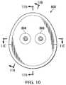
- FIG. 10is a top view illustrating additional details that may be associated with some embodiments of the instillation regulator of FIG. 8 ;
- FIG. 11Ais a cross-section of the instillation regulator shown in FIG. 10 taken along line 11 A- 11 A;
- FIG. 11Bis a cross-section of the instillation regulator shown in FIG. 10 taken along line 11 B- 11 B;
- FIG. 11Cis a cross-section of the instillation regulator shown in FIG. 10 taken along line 11 C- 11 C.
- FIG. 1is a simplified block diagram of an example embodiment of a therapy system 100 that can provide negative-pressure therapy with instillation of topical treatment solutions in accordance with this specification.
- the therapy system 100may include a dressing and a negative-pressure source.
- a dressing 102may be fluidly coupled to a negative-pressure source 104 , as illustrated in FIG. 1 .
- a regulatorsuch as a pressure regulator 106 , may also be fluidly coupled to the dressing 102 and the negative-pressure source 104 .
- a dressingmay include a cover and a tissue interface.
- the dressing 102for example, includes a cover 108 and a tissue interface 110 .
- the therapy system 100may also include an exudate container, such as a container 112 , coupled to the dressing 102 and to the negative-pressure source 104 .
- the therapy system 100may also include a source of instillation solution.
- a solution source 114may be fluidly coupled to the dressing 102 , as illustrated in the example embodiment of FIG. 1 .
- a second regulatorsuch as an instillation regulator 116 , may also be fluidly coupled to the solution source 114 and the dressing 102 .
- the instillation regulator 116may also be fluidly coupled to the negative-pressure source 104 through the dressing 102 , as illustrated in the example of FIG. 1 .
- components of the therapy system 100may be coupled directly or indirectly.
- the negative-pressure source 104may be directly coupled to the pressure regulator 106 and indirectly coupled to the dressing 102 through the pressure regulator 106 .
- componentsmay be coupled by virtue of physical proximity, being integral to a single structure, or being formed from the same piece of material. Coupling may also include mechanical, thermal, electrical, or chemical coupling (such as a chemical bond) in some contexts.
- Componentsmay also be fluidly coupled to each other to provide a path for transferring fluids (i.e., liquid and/or gas) between the components.
- componentsmay be fluidly coupled through a tube.
- a tubeis an elongated, cylindrical structure with some flexibility, but the geometry and rigidity may vary.
- a fluid conductormay also be integrally molded into a component in some embodiments.
- the tissue interface 110may be placed within, over, on, or otherwise proximate to a tissue site.
- the cover 108may be placed over the tissue interface 110 and sealed to tissue near the tissue site.
- the cover 108may be sealed to undamaged epidermis peripheral to a tissue site.
- the dressing 102can provide a sealed therapeutic environment proximate to a tissue site, substantially isolated from the external environment, and the negative-pressure source 104 can reduce the pressure in the sealed therapeutic environment. Negative pressure applied across a tissue site through the tissue interface 110 in the sealed therapeutic environment can induce macro-strain and micro-strain in the tissue site, as well as remove exudate and other fluid from the tissue site, which can be collected in the container 112 and disposed of properly.
- the fluid mechanics of using a negative-pressure source to reduce pressure in another component or location, such as within a sealed therapeutic environmentcan be mathematically complex.
- the basic principles of fluid mechanics applicable to negative-pressure therapy and instillationare generally well-known to those skilled in the art.
- fluidflows toward lower pressure along a fluid path.
- downstreamtypically implies something in a fluid path relatively closer to a source of negative pressure or further away from a source of positive pressure; conversely, the term “upstream” implies something relatively further away from a source of negative pressure or closer to a source of positive pressure.
- inletor “outlet” in such a frame of reference, and the process of reducing pressure may be described illustratively herein as “delivering,” “distributing,” or “generating” reduced pressure, for example. This orientation is generally presumed for purposes of describing various features and components herein.
- tissue sitein this context broadly refers to a wound or defect located on or within tissue, including but not limited to, bone tissue, adipose tissue, muscle tissue, neural tissue, dermal tissue, vascular tissue, connective tissue, cartilage, tendons, or ligaments.
- a woundmay include chronic, acute, traumatic, subacute, and dehisced wounds, partial-thickness burns, ulcers (such as diabetic, pressure, or venous insufficiency ulcers), flaps, and grafts, for example.
- tissue sitemay also refer to areas of any tissue that are not necessarily wounded or defective, but are instead areas in which it may be desirable to add or promote the growth of additional tissue. For example, negative pressure may be used in certain tissue areas to grow additional tissue that may be harvested and transplanted to another tissue location.
- Negative pressuregenerally refers to a pressure less than a local ambient pressure, such as the ambient pressure in a local environment external to a sealed therapeutic environment provided by the dressing 102 .
- the local ambient pressuremay also be the atmospheric pressure at which a tissue site is located.
- negative pressuremay be a pressure less than a hydrostatic pressure associated with tissue at the tissue site. Unless otherwise indicated, values of pressure stated herein are gauge pressures.
- references to increases in negative pressuretypically refer to a decrease in absolute pressure, while decreases in negative pressure typically refer to an increase in absolute pressure.
- a negative-pressure sourcesuch as the negative-pressure source 104
- a negative-pressure sourcemay be housed within or used in conjunction with other components, such as sensors, processing units, alarm indicators, memory, databases, software, display devices, or user interfaces that further facilitate negative-pressure therapy.
- the pressureis generally a low vacuum, also commonly referred to as a rough vacuum, between ⁇ 5 mm Hg ( ⁇ 667 Pa) and ⁇ 500 mm Hg ( ⁇ 66.7 kPa).
- a rough vacuumbetween ⁇ 5 mm Hg ( ⁇ 667 Pa) and ⁇ 500 mm Hg ( ⁇ 66.7 kPa).
- Common therapeutic rangesare between ⁇ 75 mm Hg ( ⁇ 9.9 kPa) and ⁇ 300 mm Hg ( ⁇ 39.9 kPa).
- the tissue interface 110can be generally adapted to contact a tissue site.
- the tissue interface 110may be partially or fully in contact with a tissue site. If a tissue site is a wound, for example, the tissue interface 110 may partially or completely fill the wound, or may be placed over the wound.
- the tissue interface 110may take many forms, and may have many sizes, shapes, or thicknesses depending on a variety of factors, such as the type of treatment being implemented or the nature and size of a tissue site.
- the size and shape of the tissue interface 110may be adapted to the contours of deep and irregular shaped tissue sites.
- the tissue interfacemay be provided in a spiral cut sheet.
- any or all of the surfaces of the tissue interface 110may have an uneven, coarse, or jagged profile that can induce micro-strains and stresses at a tissue site.
- the tissue interface 110may be a manifold.
- a “manifold” in this contextgenerally includes any substance or structure providing a plurality of pathways adapted to collect or distribute fluid across a tissue site.
- a manifoldmay be adapted to receive negative pressure from a source and distribute negative pressure through multiple apertures across a tissue site, which may have the effect of collecting fluid from across a tissue site and drawing the fluid toward the source.
- the fluid pathmay be reversed or a secondary fluid path may be provided to facilitate distributing fluid across a tissue site.
- the pathways of a manifoldmay be interconnected to improve distribution or collection of fluids across a tissue site.
- cellular foam, open-cell foam, reticulated foam, porous tissue collections, and other porous materialsuch as gauze or felted mat generally include pores, edges, and/or walls adapted to form interconnected fluid pathways.
- Liquids, gels, and other foamsmay also include or be cured to include apertures and fluid pathways.
- a manifoldmay be a porous foam material having interconnected cells or pores adapted to distribute negative pressure across a tissue site.
- the foam materialmay be either hydrophobic or hydrophilic.
- the pore size of a foam materialmay vary according to needs of a prescribed therapy.
- the tissue interface 110may be a foam having pore sizes in a range of 400-600 microns.
- the tensile strength of the tissue interface 110may also vary according to needs of a prescribed therapy.
- the tensile strength of a foammay be increased for instillation of topical treatment solutions.
- the tissue interface 110may be an open-cell, reticulated polyurethane foam such as GranuFoam® dressing available from Kinetic Concepts, Inc. of San Antonio, Tex.; in other embodiments the tissue interface 110 may be an open-cell, reticulated polyurethane foam such as a VeraFlo® foam, also available from Kinetic Concepts, Inc., of San Antonio, Tex.
- the tissue interface 110may be made from a hydrophilic material
- the tissue interface 110may also wick fluid away from a tissue site, while continuing to distribute negative pressure to the tissue site.
- the wicking properties of the tissue interface 110may draw fluid away from a tissue site by capillary flow or other wicking mechanisms.
- An example of a hydrophilic foamis a polyvinyl alcohol, open-cell foam such as V.A.C. WhiteFoam® dressing available from Kinetic Concepts, Inc. of San Antonio, Tex.
- Other hydrophilic foamsmay include those made from polyether.
- Other foams that may exhibit hydrophilic characteristicsinclude hydrophobic foams that have been treated or coated to provide hydrophilicity.
- the tissue interface 110may be constructed from bioresorbable materials. Suitable bioresorbable materials may include, without limitation, a polymeric blend of polylactic acid (PLA) and polyglycolic acid (PGA). The polymeric blend may also include without limitation polycarbonates, polyfumarates, and capralactones.
- the tissue interface 110may further serve as a scaffold for new cell-growth, or a scaffold material may be used in conjunction with the tissue interface 110 to promote cell-growth.
- a scaffoldis generally a substance or structure used to enhance or promote the growth of cells or formation of tissue, such as a three-dimensional porous structure that provides a template for cell growth.
- Illustrative examples of scaffold materialsinclude calcium phosphate, collagen, PLA/PGA, coral hydroxy apatites, carbonates, or processed allograft materials.
- the cover 108may provide a bacterial barrier and protection from physical trauma.
- the cover 108may also be constructed from a material that can reduce evaporative losses and provide a fluid seal between two components or two environments, such as between a therapeutic environment and a local external environment.
- the cover 108may be, for example, an elastomeric film or membrane that can provide a seal adequate to maintain a negative pressure at a tissue site for a given negative-pressure source.
- the cover 108may be a polymer drape, such as a polyurethane film, that is permeable to water vapor but impermeable to liquid. Such drapes typically have a thickness in the range of 25-50 microns. For permeable materials, the permeability generally should be low enough that a desired negative pressure may be maintained.
- An attachment devicemay be used to attach the cover 108 to an attachment surface, such as undamaged epidermis, a gasket, or another cover.
- the attachment devicemay take many forms.
- an attachment devicemay be a medically-acceptable, pressure-sensitive adhesive that extends about a periphery, a portion, or the entire cover 108 .
- some or all of the cover 108may be coated with an acrylic adhesive having a coating weight between 25-65 grams per square meter (g.s.m.). Thicker adhesives, or combinations of adhesives, may be applied in some embodiments to improve the seal and reduce leaks.
- Other example embodiments of an attachment devicemay include a double-sided tape, paste, hydrocolloid, hydrogel, silicone gel, or organogel.
- the container 112is representative of a container, canister, pouch, or other storage component, which can be used to manage exudate and other fluid withdrawn from a tissue site.
- a rigid containermay be preferred or required for collecting, storing, and disposing of fluid.
- fluidmay be properly disposed of without rigid container storage, and a re-usable container could reduce waste and costs associated with negative-pressure therapy.
- the solution source 114may also be representative of a container, canister, pouch, bag, or other storage component, which can provide a solution for instillation therapy.
- Compositions of solutionsmay vary according to a prescribed therapy, but examples of solutions that may be suitable for some prescriptions include hypochlorite-based solutions, silver nitrate (0.5%), sulfur-based solutions, biguanides, cationic solutions, and isotonic solutions.
- FIG. 2is a perspective view of an instillation regulator 200 illustrating additional details that may be associated with some embodiments of the therapy system 100 .
- the instillation regulator 200may be an example embodiment of the instillation regulator 116 of FIG. 1 .
- the instillation regulator 200generally includes a housing, which may be formed by a body 202 and a head 204 coupled to the body 202 , as shown in the example embodiment of FIG. 2 .
- Some embodiments of the head 204may include an extension 205 .
- the body 202may include a flange 206
- the head 204may include a flange 208 .
- the body 202may be cylindrical in some embodiments, as illustrated in the example of FIG.
- the head 204may be circular with a cylindrical extension 205 , also as illustrated in the example of FIG. 2 .
- the flange 206 and the flange 208may be coupled with fasteners 210 , or may be coupled with other mechanical, thermal, electrical, or chemical couplings.
- the dimensions of the flange 208may be similar to the dimensions of the flange 206 to facilitate a secure coupling.
- the instillation regulator 200may have fluid ports adapted for coupling to a tube.
- the body 202may have a negative-pressure port 212
- the head 204may have a solution inlet port 214 and a solution outlet port 216 .
- a retention cap 218may also be coupled to the head 204 in some embodiments of the instillation regulator 200 , and the body 202 may additionally comprise a vent 220 , as shown in the example embodiment of FIG. 2 .
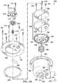
- FIG. 3A and FIG. 3Bare assembly views illustrating additional details that may be associated with some embodiments of an instillation regulator, such as the instillation regulator 200 of FIG. 2 .
- Some embodiments of the instillation regulator 200may include a piston, an elastic device, and a gasket.
- a pistoncan be a flexible or movable barrier, for example, illustrated in FIG. 3A as a piston 302 .
- An elastic devicemay be a spring or rubber, for example, illustrated in FIG. 3A as a spring 304 .
- the spring 304may be disposed within a cavity 306 of the body 202 , generally between the piston 302 and the body 202 , as illustrated in the example embodiment of FIG. 3A .
- the spring 304may be a coil spring coaxial with the piston 302 , as shown in the example of FIG. 3A .
- the cavity 306may be cylindrical, and the piston 302 may be rounded to fit within the cavity 306 of the body 202 .
- the piston 302may also reciprocate within the cavity 306 .
- a gasket 308may be disposed between the flange 206 and the flange 208 .
- the instillation regulator 200may also include an outlet check valve 309 disposed between the head 204 and the retention cap 218 .
- the outlet check valve 309may be a diaphragm valve having a diaphragm 310 and an elastic device such as a spring 312 .
- the diaphragm 310may be a flexible membrane or partition, such as a thin flexible disk.
- the spring 312may be disposed within the extension 205 over a retention boss 314 , which can restrict lateral movement of the spring 312 .
- a flow limitermay comprise a hydrophobic filter 316 and a retaining ring 318 , as illustrated in FIG. 3A and FIG. 3B .
- the hydrophobic filter 316is generally configured to be disposed in or otherwise engage the vent 220
- the retaining ring 318may be disposed around or otherwise coupled to the hydrophobic filter and the vent 220 to secure the hydrophobic filter 316 to the vent 220 .
- a flow limitermay comprise an adjustable valve, such as a needle valve.
- the head 204may include a passage configured to fluidly couple the extension 205 and the solution outlet port 216 .
- the passagemay be formed by a membrane 320 coupled to the head 204 to enclose a channel 322 formed in the head 204 .
- the piston 302may comprise a flexible seal disposed between a base and a retainer.
- the piston 302 of FIG. 3A and FIG. 3Bincludes a seal 324 , a seal base 326 , and a seal retainer 328 .
- the seal 324may be an elastomer or other flexible material, for example, while the seal base 326 and the seal retainer 328 preferably provide strength and rigidity to support the seal 324 .
- the seal base 326 and the seal retainer 328may include ribs 330 to provide further structural support.
- the seal base 326may include one or more alignment pins 332 , which can be configured to engage one or more alignment guides 334 .
- FIG. 4is a top view illustrating additional details that may be associated with some embodiments of an instillation regulator, such as the instillation regulator 200 .
- the retention cap 218may be vented to expose the diaphragm 310 to the ambient environment.
- the retention cap 218may comprise a support ring 402 and cross-bars 404 coupled to the support ring 402 .
- the cross-bars 404are generally configured to protect the diaphragm 310 and provide a fluid path between the diaphragm 310 and the ambient environment.
- a grid, a mesh, or other suitable porous structuremay be coupled to the support ring to provide similar protection and fluid communication.
- the solution inlet port 214 and the solution outlet port 216may be disposed on, in, or through the head 204 , adjacent to the retention cap 218 and outside the support ring 402 .
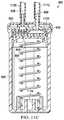
- FIG. 5Ais a sectional view of the instillation regulator 200 of FIG. 4 taken on line 5 A- 5 A, illustrating additional details that may be associated with some embodiments of the instillation regulator 200 in a first state.
- FIG. 5Bis a sectional view of the instillation regulator 200 of FIG. 4 taken on line 5 B- 5 B, illustrating additional details that may be associated with some embodiments of the instillation regulator 200 in a second state.
- the head 204can be coupled to the body 202 to enclose the piston 302 and fluidly isolate the cavity 306 from the ambient environment.
- the piston 302may partition or separate the cavity 306 into a first chamber 502 and a second chamber 504 .
- the piston 302may engage the body 202 to provide a seal between the first chamber 502 and the second chamber 504 .
- the seal 324may press against a side wall of the body 202 to fluidly isolate the first chamber 502 from the second chamber 504 .
- the diaphragm 310may be coupled to the extension 205 to form a third chamber 506 , generally defined by a portion of the head 204 , the extension 205 , and the diaphragm 310 .
- the spring 312may be disposed in the third chamber 506 between the diaphragm 310 and the head 204 .
- the spring 312may be disposed around the retention boss 314 , as shown in the instillation regulator 200 of FIG. 5A and FIG. 5B .
- a peripheral edge of the diaphragm 310may be supported by the extension 205 , and an interior portion of the diaphragm 310 may engage the spring 312 .
- the retention cap 218may be coupled to the head 204 to secure the peripheral edge of the diaphragm 310 between the retention cap 218 and the extension 205 .
- a passage 508 through the retention boss 314can fluidly couple the first chamber 502 and the third chamber 506 through the diaphragm valve 309 .
- a passage 510 in the head 204may also fluidly couple the third chamber 506 to the solution outlet port 216 .
- the passage 508 and the passage 510can provide a fluid path between the first chamber 502 and the solution outlet port 216 through the outlet check valve 309 , which may be configured to be closed by negative pressure in the first chamber 502 .
- the regulator 200may also include an inlet check valve 512 and an outlet check valve 514 .
- the inlet check valve 512may be fluidly coupled to the first chamber 502 and configured to be opened by negative pressure in the first chamber 502 .
- the outlet check valve 514may be fluidly coupled to the second chamber 504 and configured to be opened by negative pressure delivered to the negative-pressure port 212 or by an increase in pressure in the second chamber 504 .
- the inlet check valve 512may be disposed between the solution inlet port 214 and the first chamber 502
- the outlet check valve 514may be disposed between the negative-pressure port 212 and the second chamber 504 .
- the spring 304may be disposed in the second chamber 504 against the piston 302 and the body 202 to bias the piston.
- the piston spring 516may have a first end disposed around a retention boss 518 to restrict lateral movement, and may have a second end engaged to the piston 302 .
- the spring 304may bias the piston toward the head 204 .
- FIG. 6is a schematic diagram of a therapy system 600 , which may be an illustrative embodiment of the therapy system 100 having an embodiment of the instillation regulator 200 .
- the therapy system 600may include a dressing 602 and a negative-pressure therapy unit 604 .
- the dressing 602may be an example embodiment of the dressing 102 of FIG. 1 .
- the negative-pressure therapy unit 604may comprise an internal negative-pressure source (not visible in FIG. 6 ) and an exudate container 606 .
- the exudate container 606is fluidly coupled to the internal negative-pressure source when coupled to the negative-pressure therapy unit 604 , but may be detachable from the negative-pressure therapy unit 604 .
- the dressing 602may be fluidly coupled to internal negative-pressure source through the exudate container 606 .
- the negative-pressure therapy unit 604may also include a user interface 608 .
- the therapy system 600may also include an instillation solution source, such as a solution bag 610 , fluidly coupled to the dressing 602 as illustrated in the example embodiment of FIG. 6 .
- the solution bag 610may be an illustrative embodiment of the solution source 114 of FIG. 1 .
- the solution bag 610 and the dressing 602may be fluidly coupled to the instillation regulator 200 .
- the dressing 602 and the exudate container 606can provide a fluid path between the instillation regulator 200 and the negative-pressure source.
- a tube 612can fluidly couple the dressing 602 to the exudate container 606
- tubes 614can fluidly couple the dressing 602 to the instillation regulator 200
- a tube 616may also fluidly couple the solution bag 610 to the instillation regulator 200
- elbow connectors 618may be used to facilitate coupling the dressing 602 to the tube 612 and the tubes 614 , as shown in FIG. 6 .
- therapy system 600may provide intermittent or dynamic negative pressure, having negative-pressure intervals during which negative pressure is applied to the dressing 602 and venting intervals during which no negative-pressure is applied to the dressing 602 .
- the instillation regulator 200may regulate instillation during these intervals.
- the instillation regulator 200may be primed during the negative-pressure intervals, and the instillation regulator 200 may instill a solution from the solution bag 610 to the dressing 602 during venting intervals.
- the negative-pressure therapy unit 604can remove air from the second chamber 504 during a negative-pressure interval, which can develop a pressure differential across the piston 302 .
- This pressure differentialcan have the effect of moving the piston 302 , expanding the first chamber 502 , and compressing the second chamber 504 . If the first chamber 502 expands, pressure in the first chamber 502 can decrease. Negative pressure in the first chamber 502 can then have the effect of actively drawing instillation solution into the first chamber 502 from the solution bag 610 through the tube 616 and the solution inlet port 214 .
- the distance that the piston 302 travelscan determine a dosage volume of instillation solution.
- the first chamber 502may be lined with a suitable material to prevent contamination from mechanical components or lubricants.
- the first chamber 502may be lined with a film bag, an elastomeric bag, or a compressible bellows.
- Expansion of the first chamber 502may also have the effect of decreasing pressure in the third chamber 506 , as pressure between the first chamber 502 and the third chamber 506 may be equalized through the passage 508 .
- Decreased pressure in the third chamber 506may have the effect of closing the outlet check valve 309 , which can prevent instillation of solution to the dressing 602 during a negative-pressure interval.
- the dressing 602may vent to atmospheric pressure of the ambient environment, which can have the effect of increasing pressure in the second chamber 504 .
- the vent 220may also provide fluid communication between the second chamber 504 and the ambient environment, which can also have the effect increasing pressure in the second chamber 504 .
- Increased pressure in the second chamber 504 during a venting intervalcan have the effect of moving the piston 302 to compress the first chamber 502 and expand the second chamber 504 . If the first chamber 502 is compressed, pressure in the first chamber 502 can increase. Increased pressure can move solution out of the first chamber 502 through the solution outlet port 216 , instilling the solution into the dressing 602 through the tube 614 .
- the inlet check valve 512can prevent back-flow through the solution inlet port 214 during instillation, and the outlet check valve 514 can prevent solution from moving into the second chamber 504 through the negative-pressure port 212 during instillation.
- a flow limitersuch as the hydrophobic filter 316 can control the rate of venting between the second chamber 504 and the ambient environment through the vent 220 , which can also determine the rate at which the piston 302 moves and the rate at which solution can be instilled from the chamber 502 .
- the surface area of the hydrophobic filter 316can determine the vent rate and can be calibrated to provide a prescribed instillation rate.
- FIG. 7is a schematic diagram of a therapy system 700 , which may be an alternative illustrative embodiment of the therapy system 100 having an embodiment of the instillation regulator 200 .
- the therapy system 700may include a dressing 702 and a negative-pressure treatment unit 704 , analogous to the dressing 602 and the negative-pressure treatment unit 604 of therapy system 600 .
- tubes 712 and 714may be fluidly coupled to the dressing 702 using a connection interface 718 .
- connection interface 718may be a multi-port elbow connector configured to communicate negative pressure from the tube 712 , as well as conduct the passage of instillation fluid delivered through tube 714 to the dressing 702 .
- FIG. 8is a perspective view of an instillation regulator 800 , illustrating details that may be associated with another example embodiment of the instillation regulator 116 .
- the instillation regulator 800generally includes a housing, which may be formed by a body 802 and a cap 804 coupled to the body 802 , as shown in the example embodiment of FIG. 8 .
- Some embodiments of the instillation regulator 800may have fluid ports adapted for coupling to a tube.
- the instillation regulator 800may have first fluid port such as the solution inlet port 806 , which may extend through an inlet port opening 810 of the cap 804 , and a second fluid port such as the solution outlet port 808 , which may extend through an outlet port opening 812 .
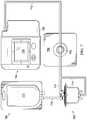
- FIG. 9A and FIG. 9Bare assembly views illustrating additional details that may be associated with some embodiments of an instillation regulator, such as the instillation regulator 800 of FIG. 8 .
- Some embodiments of the instillation regulator 800may include a piston, an elastic device, and a gasket.
- the pistoncan be a flexible or movable barrier, for example, illustrated in FIG. 9A as a piston 902 .
- An elastic devicemay be a spring or rubber, for example, illustrated in FIG. 9A as a spring 904 .
- the spring 904may be disposed within a cavity 906 of the body 802 of the instillation regulator 800 , generally between the piston 902 and the body 802 , as illustrated in the example embodiment of FIG. 9B .
- the spring 904may be a coil spring coaxial with the piston 902 , as shown in the example of FIG. 9A .
- the cavity 906may be a cylindrical bore, and the piston 902 may be rounded to fit within the cavity 906 of the body 802 .
- the piston 902may also reciprocate within the cavity 906 .
- the body 802 of the instillation regulator 800may also comprise a window 938 , which may allow viewing the interior of the instillation regulator 800 through an opening 940 .
- a window 938may allow viewing the interior of the instillation regulator 800 through an opening 940 .
- the position of the piston 902 or the fluid in the cavity 906may be viewed through the window 938 and the opening 940 in some embodiments.
- the instillation regulator 800may also include a head 908 , which may be disposed between the body 802 and the cap 804 .
- the instillation regulator 800may also include an outlet check valve 910 disposed between the head 908 and the cap 804 .
- the outlet check valve 910may be a diaphragm valve comprising a flexible membrane or partition, such as a thin flexible disk.
- a membrane 936may also be disposed between the cap 804 and a channel 927 of the head 908 .
- the head 908may comprise an extension 905 , and a valve seat 930 within the extension 905 configured to engage the outlet check valve 910 .
- a flow limitermay comprise a hydrophobic filter 916 , as illustrated in FIG. 9A and FIG. 9B .
- the hydrophobic filter 916is generally configured to be disposed in or otherwise engage a vent 919
- retaining ring 917may be disposed around or otherwise coupled to the hydrophobic filter 916 and the vent 919 to couple the hydrophobic filter 916 to the vent 919 .
- the retaining ring 917may be coupled to or integral with a sealing membrane 918 , as illustrated in the example embodiment of FIG. 9A and FIG. 9B .
- the head 908may also include a passage configured to fluidly couple the valve seat 930 to the solution outlet port 808 .
- an integrated fluid conductormay be formed by a membrane 920 coupled to the head 908 to enclose a channel 912 formed in the head 908 .
- Another passagemay fluidly couple the solution outlet port 808 to the channel 927 .
- an integrated fluid conductormay be formed by coupling the membrane 920 to the head 908 to enclose a channel 914 .
- the membrane 936may also be coupled to the head 908 to enclose the channel 927 .
- any or all of the channel 912 , the channel 914 and the channel 927may be integrally molded into the head 908 .
- the body 802may also include one or more passages configured to fluidly couple the channel 927 to the cavity 906 .
- the body 802may include a fluid conductor formed by the sealing membrane 918 coupled to the body 802 to enclose a channel 923 , and a passage 922 in the body 802 may fluidly couple the channel 923 and the channel 927 .
- either or both of the passage 922 and the channel 923may be integrally molded in the body 802 .
- the piston 902may comprise a conformable seal disposed between a base and a retainer.
- the piston 902 of FIG. 9A and FIG. 9Bincludes a seal 924 , a seal base 926 , and a seal retainer 928 .
- the seal 924may be an elastomer or other flexible material, for example, while the seal base 926 and the seal retainer 928 may be a rigid plastic to provide strength and rigidity to support the seal 924 .
- An inlet check valve 942may also be disposed between the head 908 and the seal retainer 928 , fluidly coupled to the solution inlet port 806 .
- FIG. 10is a top view illustrating additional details that may be associated with some embodiments of an instillation regulator, such as the instillation regulator 800 .
- the instillation regulator 800may have an ovate profile to accommodate the cavity 906 and the passage 922 .
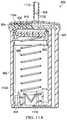
- FIG. 11Ais a sectional view of the instillation regulator 800 of FIG. 10 taken on line 11 A- 11 A, illustrating additional details that may be associated with some embodiments of the instillation regulator 800 .
- FIG. 11Bis a sectional view of the instillation regulator 800 of FIG. 10 taken on line 11 B- 11 B, illustrating additional details that may be associated with some embodiments of the instillation regulator 800 .
- FIG. 11Cis a sectional view of the instillation regulator 800 of FIG. 10 taken on line 11 C- 11 C, illustrating additional details that may be associated with some embodiments of the instillation regulator 800 . Assembled as shown in the example embodiment of FIG.
- the head 908can be coupled to the body 802 to fluidly isolate the cavity 906 from the ambient environment, and the piston 902 may partition or separate the cavity 906 into a first chamber 1102 and a second chamber 1104 . Moreover, the piston 902 may engage the body 202 to provide a seal between the first chamber 1102 and the second chamber 1104 . For example, as shown in the example embodiment of FIG. 11A , the seal 924 may press against a side wall of the body 802 to fluidly isolate the first chamber 1102 from the second chamber 1104 .
- the outlet check valve 910may be coupled to the extension 905 to form a third chamber 1124 , generally defined by a portion of the head 908 , the extension 905 , and the outlet check valve 910 .
- a peripheral edge of the outlet check valve 910may be supported or coupled to the extension 905 .
- the cap 804be disposed on the head 908 to secure the outlet check valve 910 to the extension 905 .
- a passage through the valve seat 930may fluidly couple the first chamber 1102 and the third chamber 1124 .
- the channel 912may also fluidly couple the third chamber 1124 to the solution outlet port 808 .
- the inlet check valve 942may be fluidly coupled to the first chamber 1102 and configured to be opened by negative pressure in the first chamber 1102 . Some embodiments may also comprise an outlet check valve 910 fluidly coupled to the second chamber 1104 and configured to be opened by negative pressure in the channel 923 or by an increased pressure in the second chamber 1104 .
- the inlet check valve 942may be disposed between the solution inlet port 806 and the first chamber 1102
- the outlet check valve 1114may be disposed between the solution outlet port 808 and the second chamber 1104 .
- the spring 904may be disposed between the piston 902 and the body 802 in some embodiments.
- the spring 904may have a first end disposed around a retention boss 1118 to restrict lateral movement, and may have a second end engaged to the piston 902 .
- the instillation regulator 800may be primed during negative-pressure intervals, and may instill a solution during venting intervals.
- negative pressurecan be supplied by a negative-pressure therapy unit (not shown) and delivered by a tube 1112 to the instillation regulator 800 .
- negative pressuremay be delivered to the second chamber 1104 through the solution outlet port 808 , the passage 922 , and the channel 923 .
- Negative pressure in the second chamber 1104can move the piston 902 , expanding the first chamber 1102 and compressing the second chamber 1104 . If the first chamber 1102 expands, pressure in the first chamber 1102 can decrease proportionately.
- Negative pressure in the first chamber 1102can have the effect of actively drawing instillation solution into the first chamber 1102 through the solution inlet port 806 .
- the distance that the piston 902 travelscan determine a dosage volume of instillation solution.
- the first chamber 1102may be lined with a suitable material to prevent contamination from mechanical components or lubricants.
- the first chamber 1102may be lined with a film bag, an elastomeric bag, or a compressible bellows.
- the instillation dosagemay be adjusted. Such capability may be achieved by adjusting the distance traveled of the movable components during negative-pressure and venting intervals.
- the spring 904may be compressed so that the distance traveled by the piston 902 will be limited. This may result from more quickly reaching the point where the negative pressure applied to the second chamber 1104 for compressing the spring 904 can no longer overcome the force exerted by the spring 904 .
- Other example embodimentsmay adjust the instillation dosage by reducing the height of the second chamber 1104 , for example, by screwing the first chamber 1102 further into the second chamber 1104 using a threaded mechanism.
- Yet another examplemay include controlling the dosage of instillation fluid delivered by limiting the travel of the piston 902 within the second chamber 1104 by adjusting the height of a stop block located within the second chamber 1104 , under the piston 902 .
- Additional examplesmay include restricting the flow of instillation fluid through either the solution inflow tube 1120 or the solution outflow tube 1112 using, for example, a valve, or by restricting the rate at which the piston 902 recovers.
- Expansion of the first chamber 1102may also have the effect of decreasing pressure in the third chamber 1124 , as pressure between the first chamber 1102 and the third chamber 1124 may be equalized through the passage 1126 .
- the decreased pressure in the third chamber 1124may have the effect of closing the outlet check valve 910 , which can prevent instillation of solution to a dressing during a negative-pressure interval.
- the vent 919may provide fluid communication between the second chamber 1104 and the ambient environment, which can also have the effect of increasing pressure in the second chamber 1104 .
- Increased pressure in the second chamber 1104 during a venting intervalcan have the effect of moving the piston 902 , compressing the first chamber 1102 and expanding the second chamber 1104 . If the first chamber 1102 is compressed, pressure in the first chamber 1102 can increase proportionately. The resulting increase in pressure can move solution out of the first chamber 1102 through the valve seat 930 , the channel 912 , and the solution outlet port 808 , instilling solution to a tissue site through the solution outflow tube 1112 .
- the inlet check valve 942can prevent back-flow through the solution inlet port 806 during instillation, and the outlet check valve 1114 can prevent solution from moving into the second chamber 1104 from the channel 923 during instillation.
- a flow limitersuch as the hydrophobic filter 916 can control the rate of venting between the second chamber 1104 and the ambient environment through the vent 919 , which can also determine the rate at which the piston 902 moves and the rate at which solution can be instilled from the first chamber 1102 .
- the surface area of the hydrophobic filter 916can determine the vent rate and can be calibrated to provide a prescribed instillation rate.
- an instillation regulator described abovecan combine instillation therapy with negative-pressure therapy without an additional pump.
- the use of a single pump, rather than two separate pumps,may provide a more compact, lighter, and less expensive therapy system.
- embodiments of the instillation regulator described abovemay be incorporated into therapy systems without making changes to existing negative-pressure therapy devices that use intermittent therapy.
- the use of an instillation regulator such as described hereinmay offer a way to ensure that reliable and repeatable dosages of instillation fluid are delivered to a tissue site. Dosage amounts may also be easily adjusted through the use of an instillation regulator.
- the instillation regulator embodiments described abovemay also provide an ability to better deal with head heights when instilling fluid, as compared to other non-powered or powered delivery systems.
Landscapes
- Health & Medical Sciences (AREA)
- Heart & Thoracic Surgery (AREA)
- Public Health (AREA)
- Veterinary Medicine (AREA)
- Engineering & Computer Science (AREA)
- Biomedical Technology (AREA)
- General Health & Medical Sciences (AREA)
- Life Sciences & Earth Sciences (AREA)
- Animal Behavior & Ethology (AREA)
- Hematology (AREA)
- Anesthesiology (AREA)
- Vascular Medicine (AREA)
- Pulmonology (AREA)
- Oral & Maxillofacial Surgery (AREA)
- Surgery (AREA)
- Physics & Mathematics (AREA)
- Fluid Mechanics (AREA)
- Media Introduction/Drainage Providing Device (AREA)
- External Artificial Organs (AREA)
- Infusion, Injection, And Reservoir Apparatuses (AREA)
- Pharmaceuticals Containing Other Organic And Inorganic Compounds (AREA)
Abstract
Description
Claims (26)
Priority Applications (1)
| Application Number | Priority Date | Filing Date | Title |
|---|---|---|---|
| US15/510,185US10786608B2 (en) | 2014-09-10 | 2015-09-10 | Dynamic negative-pressure therapy with instillation |
Applications Claiming Priority (3)
| Application Number | Priority Date | Filing Date | Title |
|---|---|---|---|
| US201462048615P | 2014-09-10 | 2014-09-10 | |
| PCT/US2015/049476WO2016040671A1 (en) | 2014-09-10 | 2015-09-10 | Dynamic negative-pressure therapy with instillation |
| US15/510,185US10786608B2 (en) | 2014-09-10 | 2015-09-10 | Dynamic negative-pressure therapy with instillation |
Publications (2)
| Publication Number | Publication Date |
|---|---|
| US20170246363A1 US20170246363A1 (en) | 2017-08-31 |
| US10786608B2true US10786608B2 (en) | 2020-09-29 |
Family
ID=54150732
Family Applications (1)
| Application Number | Title | Priority Date | Filing Date |
|---|---|---|---|
| US15/510,185Active2038-01-31US10786608B2 (en) | 2014-09-10 | 2015-09-10 | Dynamic negative-pressure therapy with instillation |
Country Status (8)
| Country | Link |
|---|---|
| US (1) | US10786608B2 (en) |
| EP (2) | EP3488881B1 (en) |
| JP (1) | JP6832845B2 (en) |
| CN (1) | CN106714858B (en) |
| AU (1) | AU2015314994B2 (en) |
| CA (1) | CA2960671A1 (en) |
| TR (1) | TR201902009T4 (en) |
| WO (1) | WO2016040671A1 (en) |
Cited By (1)
| Publication number | Priority date | Publication date | Assignee | Title |
|---|---|---|---|---|
| US20230390479A1 (en)* | 2022-06-01 | 2023-12-07 | Michael McNally | Manual suction device |
Families Citing this family (27)
| Publication number | Priority date | Publication date | Assignee | Title |
|---|---|---|---|---|
| DK3288508T3 (en) | 2015-04-27 | 2020-03-09 | Smith & Nephew | REDUCED PRESSURE DEVICES |
| EP3426206B1 (en) | 2016-03-07 | 2023-05-10 | Smith & Nephew plc | Wound treatment apparatuses and methods with negative pressure source integrated into wound dressing |
| JP2017177073A (en)* | 2016-03-31 | 2017-10-05 | テルモ株式会社 | Applicator |
| CA3022184A1 (en) | 2016-04-26 | 2017-11-02 | Smith & Nephew Plc | Wound dressings and methods of use with integrated negative pressure source having a fluid ingress inhibition component |
| US11096831B2 (en) | 2016-05-03 | 2021-08-24 | Smith & Nephew Plc | Negative pressure wound therapy device activation and control |
| CA3038206A1 (en) | 2016-05-03 | 2017-11-09 | Smith & Nephew Plc | Optimizing power transfer to negative pressure sources in negative pressure therapy systems |
| WO2017191158A1 (en) | 2016-05-03 | 2017-11-09 | Smith & Nephew Plc | Systems and methods for driving negative pressure sources in negative pressure therapy systems |
| US11185624B2 (en) | 2016-06-03 | 2021-11-30 | Kci Licensing, Inc. | Negative-pressure therapy with disposable instillation pump chamber |
| WO2018037075A1 (en) | 2016-08-25 | 2018-03-01 | Smith & Nephew Plc | Absorbent negative pressure wound therapy dressing |
| EP3519001B1 (en) | 2016-09-30 | 2025-05-21 | Smith & Nephew plc | Negative pressure wound treatment apparatuses and methods with integrated electronics |
| EP3551244A1 (en) | 2016-12-12 | 2019-10-16 | Smith & Nephew PLC | Pressure wound therapy status indication via external device |
| EP3592312B1 (en) | 2017-03-08 | 2024-01-10 | Smith & Nephew plc | Negative pressure wound therapy device control in presence of fault condition |
| JP7121050B2 (en) | 2017-05-09 | 2022-08-17 | スミス アンド ネフュー ピーエルシー | Redundant control of negative pressure wound therapy systems |
| EP4275711A3 (en)* | 2017-07-18 | 2024-02-28 | 3M Innovative Properties Company | Negative-pressure therapy with adjustable instillation pump chamber |
| GB201718070D0 (en) | 2017-11-01 | 2017-12-13 | Smith & Nephew | Negative pressure wound treatment apparatuses and methods with integrated electronics |
| CA3074780A1 (en) | 2017-09-13 | 2019-03-21 | Smith & Nephew Plc | Negative pressure wound treatment apparatuses and methods with integrated electronics |
| GB201718072D0 (en) | 2017-11-01 | 2017-12-13 | Smith & Nephew | Negative pressure wound treatment apparatuses and methods with integrated electronics |
| GB201718054D0 (en) | 2017-11-01 | 2017-12-13 | Smith & Nephew | Sterilization of integrated negative pressure wound treatment apparatuses and sterilization methods |
| US11497653B2 (en) | 2017-11-01 | 2022-11-15 | Smith & Nephew Plc | Negative pressure wound treatment apparatuses and methods with integrated electronics |
| US10624794B2 (en) | 2018-02-12 | 2020-04-21 | Healyx Labs, Inc. | Negative pressure wound therapy systems, devices, and methods |
| US11806216B2 (en)* | 2018-07-16 | 2023-11-07 | Kci Licensing, Inc. | Fluid instillation apparatus for use with negative-pressure system incorporating wireless therapy monitoring |
| USD898925S1 (en) | 2018-09-13 | 2020-10-13 | Smith & Nephew Plc | Medical dressing |
| EP3914308B1 (en)* | 2019-01-25 | 2024-05-15 | Solventum Intellectual Properties Company | Systems for instillation purging |
| US20200268989A1 (en)* | 2019-02-27 | 2020-08-27 | Boehringer Technologies, Lp | System and regulator device for evacuating smoke from a laparoscopic field and method of evacuating smoke from a laparoscopic field |
| GB201903774D0 (en) | 2019-03-20 | 2019-05-01 | Smith & Nephew | Negative pressure wound treatment apparatuses and methods with integrated electronics |
| GB201907716D0 (en) | 2019-05-31 | 2019-07-17 | Smith & Nephew | Systems and methods for extending operational time of negative pressure wound treatment apparatuses |
| US20210113764A1 (en)* | 2019-10-16 | 2021-04-22 | Carefusion 303, Inc. | Drip chamber with needle valve |
Citations (139)
| Publication number | Priority date | Publication date | Assignee | Title |
|---|---|---|---|---|
| US1355846A (en) | 1920-02-06 | 1920-10-19 | David A Rannells | Medical appliance |
| US2547758A (en) | 1949-01-05 | 1951-04-03 | Wilmer B Keeling | Instrument for treating the male urethra |
| US2632443A (en) | 1949-04-18 | 1953-03-24 | Eleanor P Lesher | Surgical dressing |
| GB692578A (en) | 1949-09-13 | 1953-06-10 | Minnesota Mining & Mfg | Improvements in or relating to drape sheets for surgical use |
| US2682873A (en) | 1952-07-30 | 1954-07-06 | Johnson & Johnson | General purpose protective dressing |
| US2910763A (en) | 1955-08-17 | 1959-11-03 | Du Pont | Felt-like products |
| US2969057A (en) | 1957-11-04 | 1961-01-24 | Brady Co W H | Nematodic swab |
| US3066672A (en) | 1960-09-27 | 1962-12-04 | Jr William H Crosby | Method and apparatus for serial sampling of intestinal juice |
| US3367332A (en) | 1965-08-27 | 1968-02-06 | Gen Electric | Product and process for establishing a sterile area of skin |
| US3520300A (en) | 1967-03-15 | 1970-07-14 | Amp Inc | Surgical sponge and suction device |
| US3568675A (en) | 1968-08-30 | 1971-03-09 | Clyde B Harvey | Fistula and penetrating wound dressing |
| US3648692A (en) | 1970-12-07 | 1972-03-14 | Parke Davis & Co | Medical-surgical dressing for burns and the like |
| US3682180A (en) | 1970-06-08 | 1972-08-08 | Coilform Co Inc | Drain clip for surgical drain |
| FR2203437A5 (en)* | 1972-10-18 | 1974-05-10 | Chancholle Andre | |
| US3826254A (en) | 1973-02-26 | 1974-07-30 | Verco Ind | Needle or catheter retaining appliance |
| US3901629A (en) | 1972-10-18 | 1975-08-26 | Andre Robert Chancholle | Aspirator-ejector adapted to aspirate and to supply two fluids without mixing them |
| DE2640413A1 (en) | 1976-09-08 | 1978-03-09 | Wolf Gmbh Richard | CATHETER MONITORING DEVICE |
| US4080970A (en) | 1976-11-17 | 1978-03-28 | Miller Thomas J | Post-operative combination dressing and internal drain tube with external shield and tube connector |
| US4096853A (en) | 1975-06-21 | 1978-06-27 | Hoechst Aktiengesellschaft | Device for the introduction of contrast medium into an anus praeter |
| US4139004A (en) | 1977-02-17 | 1979-02-13 | Gonzalez Jr Harry | Bandage apparatus for treating burns |
| US4165748A (en) | 1977-11-07 | 1979-08-28 | Johnson Melissa C | Catheter tube holder |
| US4184510A (en) | 1977-03-15 | 1980-01-22 | Fibra-Sonics, Inc. | Valued device for controlling vacuum in surgery |
| WO1980002182A1 (en) | 1979-04-06 | 1980-10-16 | J Moss | Portable suction device for collecting fluids from a closed wound |
| US4233969A (en) | 1976-11-11 | 1980-11-18 | Lock Peter M | Wound dressing materials |
| US4245630A (en) | 1976-10-08 | 1981-01-20 | T. J. Smith & Nephew, Ltd. | Tearable composite strip of materials |
| US4256109A (en) | 1978-07-10 | 1981-03-17 | Nichols Robert L | Shut off valve for medical suction apparatus |
| US4261363A (en) | 1979-11-09 | 1981-04-14 | C. R. Bard, Inc. | Retention clips for body fluid drains |
| US4275721A (en) | 1978-11-28 | 1981-06-30 | Landstingens Inkopscentral Lic, Ekonomisk Forening | Vein catheter bandage |
| US4284079A (en) | 1979-06-28 | 1981-08-18 | Adair Edwin Lloyd | Method for applying a male incontinence device |
| US4297995A (en) | 1980-06-03 | 1981-11-03 | Key Pharmaceuticals, Inc. | Bandage containing attachment post |
| US4333468A (en) | 1980-08-18 | 1982-06-08 | Geist Robert W | Mesentery tube holder apparatus |
| US4373519A (en) | 1981-06-26 | 1983-02-15 | Minnesota Mining And Manufacturing Company | Composite wound dressing |
| US4382441A (en) | 1978-12-06 | 1983-05-10 | Svedman Paul | Device for treating tissues, for example skin |
| US4392853A (en) | 1981-03-16 | 1983-07-12 | Rudolph Muto | Sterile assembly for protecting and fastening an indwelling device |
| US4392858A (en) | 1981-07-16 | 1983-07-12 | Sherwood Medical Company | Wound drainage device |
| US4419097A (en) | 1981-07-31 | 1983-12-06 | Rexar Industries, Inc. | Attachment for catheter tube |
| EP0100148A1 (en) | 1982-07-06 | 1984-02-08 | Dow Corning Limited | Medical-surgical dressing and a process for the production thereof |
| US4465485A (en) | 1981-03-06 | 1984-08-14 | Becton, Dickinson And Company | Suction canister with unitary shut-off valve and filter features |
| EP0117632A2 (en) | 1983-01-27 | 1984-09-05 | Johnson & Johnson Products Inc. | Adhesive film dressing |
| US4475909A (en) | 1982-05-06 | 1984-10-09 | Eisenberg Melvin I | Male urinary device and method for applying the device |
| US4480638A (en) | 1980-03-11 | 1984-11-06 | Eduard Schmid | Cushion for holding an element of grafted skin |
| US4486190A (en) | 1982-12-27 | 1984-12-04 | Consolidated Controls Corporation | Precision medication dispensing system and method |
| US4525166A (en) | 1981-11-21 | 1985-06-25 | Intermedicat Gmbh | Rolled flexible medical suction drainage device |
| US4525374A (en) | 1984-02-27 | 1985-06-25 | Manresa, Inc. | Treating hydrophobic filters to render them hydrophilic |
| US4540412A (en) | 1983-07-14 | 1985-09-10 | The Kendall Company | Device for moist heat therapy |
| US4543100A (en) | 1983-11-01 | 1985-09-24 | Brodsky Stuart A | Catheter and drain tube retainer |
| US4548202A (en) | 1983-06-20 | 1985-10-22 | Ethicon, Inc. | Mesh tissue fasteners |
| US4551139A (en) | 1982-02-08 | 1985-11-05 | Marion Laboratories, Inc. | Method and apparatus for burn wound treatment |
| EP0161865A2 (en) | 1984-05-03 | 1985-11-21 | Smith and Nephew Associated Companies p.l.c. | Adhesive wound dressing |
| US4569348A (en) | 1980-02-22 | 1986-02-11 | Velcro Usa Inc. | Catheter tube holder strap |
| AU550575B2 (en) | 1981-08-07 | 1986-03-27 | Richard Christian Wright | Wound drainage device |
| US4605399A (en) | 1984-12-04 | 1986-08-12 | Complex, Inc. | Transdermal infusion device |
| US4608041A (en) | 1981-10-14 | 1986-08-26 | Frese Nielsen | Device for treatment of wounds in body tissue of patients by exposure to jets of gas |
| US4640688A (en) | 1985-08-23 | 1987-02-03 | Mentor Corporation | Urine collection catheter |
| US4655754A (en) | 1984-11-09 | 1987-04-07 | Stryker Corporation | Vacuum wound drainage system and lipids baffle therefor |
| US4664662A (en) | 1984-08-02 | 1987-05-12 | Smith And Nephew Associated Companies Plc | Wound dressing |
| WO1987004626A1 (en) | 1986-01-31 | 1987-08-13 | Osmond, Roger, L., W. | Suction system for wound and gastro-intestinal drainage |
| US4710165A (en) | 1985-09-16 | 1987-12-01 | Mcneil Charles B | Wearable, variable rate suction/collection device |
| US4733659A (en) | 1986-01-17 | 1988-03-29 | Seton Company | Foam bandage |
| GB2195255A (en) | 1986-09-30 | 1988-04-07 | Vacutec Uk Limited | Method and apparatus for vacuum treatment of an epidermal surface |
| US4743232A (en) | 1986-10-06 | 1988-05-10 | The Clinipad Corporation | Package assembly for plastic film bandage |
| GB2197789A (en) | 1986-11-28 | 1988-06-02 | Smiths Industries Plc | Anti-foaming disinfectants used in surgical suction apparatus |
| US4758220A (en) | 1985-09-26 | 1988-07-19 | Alcon Laboratories, Inc. | Surgical cassette proximity sensing and latching apparatus |
| US4787888A (en) | 1987-06-01 | 1988-11-29 | University Of Connecticut | Disposable piezoelectric polymer bandage for percutaneous delivery of drugs and method for such percutaneous delivery (a) |
| US4826494A (en) | 1984-11-09 | 1989-05-02 | Stryker Corporation | Vacuum wound drainage system |
| US4838883A (en) | 1986-03-07 | 1989-06-13 | Nissho Corporation | Urine-collecting device |
| US4840187A (en) | 1986-09-11 | 1989-06-20 | Bard Limited | Sheath applicator |
| US4863449A (en) | 1987-07-06 | 1989-09-05 | Hollister Incorporated | Adhesive-lined elastic condom cathether |
| US4872450A (en) | 1984-08-17 | 1989-10-10 | Austad Eric D | Wound dressing and method of forming same |
| US4878901A (en) | 1986-10-10 | 1989-11-07 | Sachse Hans Ernst | Condom catheter, a urethral catheter for the prevention of ascending infections |
| GB2220357A (en) | 1988-05-28 | 1990-01-10 | Smiths Industries Plc | Medico-surgical containers |
| US4897081A (en) | 1984-05-25 | 1990-01-30 | Thermedics Inc. | Percutaneous access device |
| US4906233A (en) | 1986-05-29 | 1990-03-06 | Terumo Kabushiki Kaisha | Method of securing a catheter body to a human skin surface |
| US4906240A (en) | 1988-02-01 | 1990-03-06 | Matrix Medica, Inc. | Adhesive-faced porous absorbent sheet and method of making same |
| US4919654A (en) | 1988-08-03 | 1990-04-24 | Kalt Medical Corporation | IV clamp with membrane |
| CA2005436A1 (en) | 1988-12-13 | 1990-06-13 | Glenda G. Kalt | Transparent tracheostomy tube dressing |
| US4941882A (en) | 1987-03-14 | 1990-07-17 | Smith And Nephew Associated Companies, P.L.C. | Adhesive dressing for retaining a cannula on the skin |
| US4946448A (en) | 1989-10-23 | 1990-08-07 | Kendall Mcgaw Laboratories, Inc. | Check valve for use with intravenous pump |
| US4953565A (en) | 1986-11-26 | 1990-09-04 | Shunro Tachibana | Endermic application kits for external medicines |
| WO1990010424A1 (en) | 1989-03-16 | 1990-09-20 | Smith & Nephew Plc | Absorbent devices and precursors therefor |
| US4969880A (en) | 1989-04-03 | 1990-11-13 | Zamierowski David S | Wound dressing and treatment method |
| US4985019A (en) | 1988-03-11 | 1991-01-15 | Michelson Gary K | X-ray marker |
| GB2235877A (en) | 1989-09-18 | 1991-03-20 | Antonio Talluri | Closed wound suction apparatus |
| US5037397A (en) | 1985-05-03 | 1991-08-06 | Medical Distributors, Inc. | Universal clamp |
| US5086170A (en) | 1989-01-16 | 1992-02-04 | Roussel Uclaf | Process for the preparation of azabicyclo compounds |
| US5092858A (en) | 1990-03-20 | 1992-03-03 | Becton, Dickinson And Company | Liquid gelling agent distributor device |
| US5100396A (en) | 1989-04-03 | 1992-03-31 | Zamierowski David S | Fluidic connection system and method |
| US5134994A (en) | 1990-02-12 | 1992-08-04 | Say Sam L | Field aspirator in a soft pack with externally mounted container |
| US5149331A (en) | 1991-05-03 | 1992-09-22 | Ariel Ferdman | Method and device for wound closure |
| US5167613A (en) | 1992-03-23 | 1992-12-01 | The Kendall Company | Composite vented wound dressing |
| US5176663A (en) | 1987-12-02 | 1993-01-05 | Pal Svedman | Dressing having pad with compressibility limiting elements |
| WO1993009727A1 (en) | 1991-11-14 | 1993-05-27 | Wake Forest University | Method and apparatus for treating tissue damage |
| US5215522A (en) | 1984-07-23 | 1993-06-01 | Ballard Medical Products | Single use medical aspirating device and method |
| US5232453A (en) | 1989-07-14 | 1993-08-03 | E. R. Squibb & Sons, Inc. | Catheter holder |
| US5261893A (en) | 1989-04-03 | 1993-11-16 | Zamierowski David S | Fastening system and method |
| US5278100A (en) | 1991-11-08 | 1994-01-11 | Micron Technology, Inc. | Chemical vapor deposition technique for depositing titanium silicide on semiconductor wafers |
| US5279550A (en) | 1991-12-19 | 1994-01-18 | Gish Biomedical, Inc. | Orthopedic autotransfusion system |
| US5298015A (en) | 1989-07-11 | 1994-03-29 | Nippon Zeon Co., Ltd. | Wound dressing having a porous structure |
| US5342376A (en) | 1993-05-03 | 1994-08-30 | Dermagraphics, Inc. | Inserting device for a barbed tissue connector |
| US5344415A (en) | 1993-06-15 | 1994-09-06 | Deroyal Industries, Inc. | Sterile system for dressing vascular access site |
| DE4306478A1 (en) | 1993-03-02 | 1994-09-08 | Wolfgang Dr Wagner | Drainage device, in particular pleural drainage device, and drainage method |
| WO1994020041A1 (en) | 1993-03-09 | 1994-09-15 | Wake Forest University | Wound treatment employing reduced pressure |
| US5358494A (en) | 1989-07-11 | 1994-10-25 | Svedman Paul | Irrigation dressing |
| US5437651A (en) | 1993-09-01 | 1995-08-01 | Research Medical, Inc. | Medical suction apparatus |
| US5437622A (en) | 1992-04-29 | 1995-08-01 | Laboratoire Hydrex (Sa) | Transparent adhesive dressing with reinforced starter cuts |
| DE29504378U1 (en) | 1995-03-15 | 1995-09-14 | MTG Medizinisch, technische Gerätebau GmbH, 66299 Friedrichsthal | Electronically controlled low-vacuum pump for chest and wound drainage |
| WO1996005873A1 (en) | 1994-08-22 | 1996-02-29 | Kinetic Concepts Inc. | Wound drainage equipment |
| US5527293A (en) | 1989-04-03 | 1996-06-18 | Kinetic Concepts, Inc. | Fastening system and method |
| US5549584A (en) | 1994-02-14 | 1996-08-27 | The Kendall Company | Apparatus for removing fluid from a wound |
| US5556375A (en) | 1994-06-16 | 1996-09-17 | Hercules Incorporated | Wound dressing having a fenestrated base layer |
| US5607388A (en) | 1994-06-16 | 1997-03-04 | Hercules Incorporated | Multi-purpose wound dressing |
| WO1997018007A1 (en) | 1995-11-14 | 1997-05-22 | Kci Medical Limited | Portable wound treatment apparatus |
| GB2329127A (en) | 1997-09-12 | 1999-03-17 | Kci Medical Ltd | Suction head and drape wound treatment assembly |
| US6071267A (en) | 1998-02-06 | 2000-06-06 | Kinetic Concepts, Inc. | Medical patient fluid management interface system and method |
| US6135116A (en) | 1997-07-28 | 2000-10-24 | Kci Licensing, Inc. | Therapeutic method for treating ulcers |
| US6241747B1 (en) | 1993-05-03 | 2001-06-05 | Quill Medical, Inc. | Barbed Bodily tissue connector |
| US6287316B1 (en) | 1999-03-26 | 2001-09-11 | Ethicon, Inc. | Knitted surgical mesh |
| US20020077661A1 (en) | 2000-12-20 | 2002-06-20 | Vahid Saadat | Multi-barbed device for retaining tissue in apposition and methods of use |
| US20020115951A1 (en) | 2001-02-22 | 2002-08-22 | Core Products International, Inc. | Ankle brace providing upper and lower ankle adjustment |
| US20020120185A1 (en) | 2000-05-26 | 2002-08-29 | Kci Licensing, Inc. | System for combined transcutaneous blood gas monitoring and vacuum assisted wound closure |
| US20020143286A1 (en) | 2001-03-05 | 2002-10-03 | Kci Licensing, Inc. | Vacuum assisted wound treatment apparatus and infection identification system and method |
| US6488643B1 (en) | 1998-10-08 | 2002-12-03 | Kci Licensing, Inc. | Wound healing foot wrap |
| US6493568B1 (en) | 1994-07-19 | 2002-12-10 | Kci Licensing, Inc. | Patient interface system |
| AU755496B2 (en) | 1997-09-12 | 2002-12-12 | Kci Licensing, Inc. | Surgical drape and suction head for wound treatment |
| US20030040709A1 (en) | 2001-08-22 | 2003-02-27 | Mason Jeffrey T. | Medication delivery system having selective automated or manual discharge |
| JP4129536B2 (en) | 2000-02-24 | 2008-08-06 | ヴェネテック インターナショナル,インコーポレイテッド | Highly compatible catheter anchoring system |
| US7846141B2 (en) | 2002-09-03 | 2010-12-07 | Bluesky Medical Group Incorporated | Reduced pressure treatment system |
| US8216198B2 (en) | 2009-01-09 | 2012-07-10 | Tyco Healthcare Group Lp | Canister for receiving wound exudate in a negative pressure therapy system |
| US8251979B2 (en) | 2009-05-11 | 2012-08-28 | Tyco Healthcare Group Lp | Orientation independent canister for a negative pressure wound therapy device |
| US8257327B2 (en) | 2003-10-28 | 2012-09-04 | Smith & Nephew Plc | Wound cleansing apparatus with actives |
| US20120302976A1 (en) | 2011-05-27 | 2012-11-29 | Kci Licensing, Inc. | Systems and methods for delivering fluid to a wound therapy dressing |
| US8398614B2 (en) | 2002-10-28 | 2013-03-19 | Smith & Nephew Plc | Apparatus for aspirating, irrigating and cleansing wounds |
| US8449509B2 (en) | 2004-04-05 | 2013-05-28 | Bluesky Medical Group Incorporated | Flexible reduced pressure treatment appliance |
| US8529548B2 (en) | 2004-04-27 | 2013-09-10 | Smith & Nephew Plc | Wound treatment apparatus and method |
| US8551060B2 (en) | 2008-07-17 | 2013-10-08 | Smith & Nephew, Inc. | Subatmospheric pressure mechanism for wound therapy system and related methods therefor |
| US20140188061A1 (en) | 2013-01-03 | 2014-07-03 | Kci Licensing, Inc. | Recharging negative-pressure wound therapy |
| US8926592B2 (en) | 2003-10-28 | 2015-01-06 | Smith & Nephew Plc | Wound cleansing apparatus with heat |
| US9017302B2 (en) | 2008-07-21 | 2015-04-28 | Smith & Nephew, Inc. | Thin film wound dressing |
| US9744278B2 (en)* | 2012-10-25 | 2017-08-29 | Kci Licensing, Inc. | Wound connection pad with pneumatic connection confirmation ability |
- 2015
- 2015-09-10TRTR2019/02009Tpatent/TR201902009T4/enunknown
- 2015-09-10USUS15/510,185patent/US10786608B2/enactiveActive
- 2015-09-10AUAU2015314994Apatent/AU2015314994B2/enactiveActive
- 2015-09-10WOPCT/US2015/049476patent/WO2016040671A1/enactiveApplication Filing
- 2015-09-10EPEP18215218.1Apatent/EP3488881B1/enactiveActive
- 2015-09-10EPEP15766724.7Apatent/EP3191149B1/enactiveActive
- 2015-09-10CNCN201580051432.8Apatent/CN106714858B/enactiveActive
- 2015-09-10CACA2960671Apatent/CA2960671A1/ennot_activeAbandoned
- 2015-09-10JPJP2017513072Apatent/JP6832845B2/enactiveActive
Patent Citations (159)
| Publication number | Priority date | Publication date | Assignee | Title |
|---|---|---|---|---|
| US1355846A (en) | 1920-02-06 | 1920-10-19 | David A Rannells | Medical appliance |
| US2547758A (en) | 1949-01-05 | 1951-04-03 | Wilmer B Keeling | Instrument for treating the male urethra |
| US2632443A (en) | 1949-04-18 | 1953-03-24 | Eleanor P Lesher | Surgical dressing |
| GB692578A (en) | 1949-09-13 | 1953-06-10 | Minnesota Mining & Mfg | Improvements in or relating to drape sheets for surgical use |
| US2682873A (en) | 1952-07-30 | 1954-07-06 | Johnson & Johnson | General purpose protective dressing |
| US2910763A (en) | 1955-08-17 | 1959-11-03 | Du Pont | Felt-like products |
| US2969057A (en) | 1957-11-04 | 1961-01-24 | Brady Co W H | Nematodic swab |
| US3066672A (en) | 1960-09-27 | 1962-12-04 | Jr William H Crosby | Method and apparatus for serial sampling of intestinal juice |
| US3367332A (en) | 1965-08-27 | 1968-02-06 | Gen Electric | Product and process for establishing a sterile area of skin |
| US3520300A (en) | 1967-03-15 | 1970-07-14 | Amp Inc | Surgical sponge and suction device |
| US3568675A (en) | 1968-08-30 | 1971-03-09 | Clyde B Harvey | Fistula and penetrating wound dressing |
| US3682180A (en) | 1970-06-08 | 1972-08-08 | Coilform Co Inc | Drain clip for surgical drain |
| US3648692A (en) | 1970-12-07 | 1972-03-14 | Parke Davis & Co | Medical-surgical dressing for burns and the like |
| FR2203437A5 (en)* | 1972-10-18 | 1974-05-10 | Chancholle Andre | |
| US3901629A (en) | 1972-10-18 | 1975-08-26 | Andre Robert Chancholle | Aspirator-ejector adapted to aspirate and to supply two fluids without mixing them |
| US3826254A (en) | 1973-02-26 | 1974-07-30 | Verco Ind | Needle or catheter retaining appliance |
| US4096853A (en) | 1975-06-21 | 1978-06-27 | Hoechst Aktiengesellschaft | Device for the introduction of contrast medium into an anus praeter |
| DE2640413A1 (en) | 1976-09-08 | 1978-03-09 | Wolf Gmbh Richard | CATHETER MONITORING DEVICE |
| US4245630A (en) | 1976-10-08 | 1981-01-20 | T. J. Smith & Nephew, Ltd. | Tearable composite strip of materials |
| US4233969A (en) | 1976-11-11 | 1980-11-18 | Lock Peter M | Wound dressing materials |
| US4080970A (en) | 1976-11-17 | 1978-03-28 | Miller Thomas J | Post-operative combination dressing and internal drain tube with external shield and tube connector |
| US4139004A (en) | 1977-02-17 | 1979-02-13 | Gonzalez Jr Harry | Bandage apparatus for treating burns |
| US4184510A (en) | 1977-03-15 | 1980-01-22 | Fibra-Sonics, Inc. | Valued device for controlling vacuum in surgery |
| US4165748A (en) | 1977-11-07 | 1979-08-28 | Johnson Melissa C | Catheter tube holder |
| US4256109A (en) | 1978-07-10 | 1981-03-17 | Nichols Robert L | Shut off valve for medical suction apparatus |
| US4275721A (en) | 1978-11-28 | 1981-06-30 | Landstingens Inkopscentral Lic, Ekonomisk Forening | Vein catheter bandage |
| US4382441A (en) | 1978-12-06 | 1983-05-10 | Svedman Paul | Device for treating tissues, for example skin |
| WO1980002182A1 (en) | 1979-04-06 | 1980-10-16 | J Moss | Portable suction device for collecting fluids from a closed wound |
| US4284079A (en) | 1979-06-28 | 1981-08-18 | Adair Edwin Lloyd | Method for applying a male incontinence device |
| US4261363A (en) | 1979-11-09 | 1981-04-14 | C. R. Bard, Inc. | Retention clips for body fluid drains |
| US4569348A (en) | 1980-02-22 | 1986-02-11 | Velcro Usa Inc. | Catheter tube holder strap |
| US4480638A (en) | 1980-03-11 | 1984-11-06 | Eduard Schmid | Cushion for holding an element of grafted skin |
| US4297995A (en) | 1980-06-03 | 1981-11-03 | Key Pharmaceuticals, Inc. | Bandage containing attachment post |
| US4333468A (en) | 1980-08-18 | 1982-06-08 | Geist Robert W | Mesentery tube holder apparatus |
| US4465485A (en) | 1981-03-06 | 1984-08-14 | Becton, Dickinson And Company | Suction canister with unitary shut-off valve and filter features |
| US4392853A (en) | 1981-03-16 | 1983-07-12 | Rudolph Muto | Sterile assembly for protecting and fastening an indwelling device |
| US4373519A (en) | 1981-06-26 | 1983-02-15 | Minnesota Mining And Manufacturing Company | Composite wound dressing |
| US4392858A (en) | 1981-07-16 | 1983-07-12 | Sherwood Medical Company | Wound drainage device |
| US4419097A (en) | 1981-07-31 | 1983-12-06 | Rexar Industries, Inc. | Attachment for catheter tube |
| AU550575B2 (en) | 1981-08-07 | 1986-03-27 | Richard Christian Wright | Wound drainage device |
| US4608041A (en) | 1981-10-14 | 1986-08-26 | Frese Nielsen | Device for treatment of wounds in body tissue of patients by exposure to jets of gas |
| US4525166A (en) | 1981-11-21 | 1985-06-25 | Intermedicat Gmbh | Rolled flexible medical suction drainage device |
| US4551139A (en) | 1982-02-08 | 1985-11-05 | Marion Laboratories, Inc. | Method and apparatus for burn wound treatment |
| US4475909A (en) | 1982-05-06 | 1984-10-09 | Eisenberg Melvin I | Male urinary device and method for applying the device |
| EP0100148A1 (en) | 1982-07-06 | 1984-02-08 | Dow Corning Limited | Medical-surgical dressing and a process for the production thereof |
| US4486190A (en) | 1982-12-27 | 1984-12-04 | Consolidated Controls Corporation | Precision medication dispensing system and method |
| EP0117632A2 (en) | 1983-01-27 | 1984-09-05 | Johnson & Johnson Products Inc. | Adhesive film dressing |
| US4548202A (en) | 1983-06-20 | 1985-10-22 | Ethicon, Inc. | Mesh tissue fasteners |
| US4540412A (en) | 1983-07-14 | 1985-09-10 | The Kendall Company | Device for moist heat therapy |
| US4543100A (en) | 1983-11-01 | 1985-09-24 | Brodsky Stuart A | Catheter and drain tube retainer |
| US4525374A (en) | 1984-02-27 | 1985-06-25 | Manresa, Inc. | Treating hydrophobic filters to render them hydrophilic |
| EP0161865A2 (en) | 1984-05-03 | 1985-11-21 | Smith and Nephew Associated Companies p.l.c. | Adhesive wound dressing |
| US4897081A (en) | 1984-05-25 | 1990-01-30 | Thermedics Inc. | Percutaneous access device |
| US5215522A (en) | 1984-07-23 | 1993-06-01 | Ballard Medical Products | Single use medical aspirating device and method |
| US4664662A (en) | 1984-08-02 | 1987-05-12 | Smith And Nephew Associated Companies Plc | Wound dressing |
| US4872450A (en) | 1984-08-17 | 1989-10-10 | Austad Eric D | Wound dressing and method of forming same |
| US4655754A (en) | 1984-11-09 | 1987-04-07 | Stryker Corporation | Vacuum wound drainage system and lipids baffle therefor |
| US4826494A (en) | 1984-11-09 | 1989-05-02 | Stryker Corporation | Vacuum wound drainage system |
| US4605399A (en) | 1984-12-04 | 1986-08-12 | Complex, Inc. | Transdermal infusion device |
| US5037397A (en) | 1985-05-03 | 1991-08-06 | Medical Distributors, Inc. | Universal clamp |
| US4640688A (en) | 1985-08-23 | 1987-02-03 | Mentor Corporation | Urine collection catheter |
| US4710165A (en) | 1985-09-16 | 1987-12-01 | Mcneil Charles B | Wearable, variable rate suction/collection device |
| US4758220A (en) | 1985-09-26 | 1988-07-19 | Alcon Laboratories, Inc. | Surgical cassette proximity sensing and latching apparatus |
| US4733659A (en) | 1986-01-17 | 1988-03-29 | Seton Company | Foam bandage |
| WO1987004626A1 (en) | 1986-01-31 | 1987-08-13 | Osmond, Roger, L., W. | Suction system for wound and gastro-intestinal drainage |
| US4838883A (en) | 1986-03-07 | 1989-06-13 | Nissho Corporation | Urine-collecting device |
| US4906233A (en) | 1986-05-29 | 1990-03-06 | Terumo Kabushiki Kaisha | Method of securing a catheter body to a human skin surface |
| US4840187A (en) | 1986-09-11 | 1989-06-20 | Bard Limited | Sheath applicator |
| GB2195255A (en) | 1986-09-30 | 1988-04-07 | Vacutec Uk Limited | Method and apparatus for vacuum treatment of an epidermal surface |
| US4743232A (en) | 1986-10-06 | 1988-05-10 | The Clinipad Corporation | Package assembly for plastic film bandage |
| US4878901A (en) | 1986-10-10 | 1989-11-07 | Sachse Hans Ernst | Condom catheter, a urethral catheter for the prevention of ascending infections |
| US4953565A (en) | 1986-11-26 | 1990-09-04 | Shunro Tachibana | Endermic application kits for external medicines |
| GB2197789A (en) | 1986-11-28 | 1988-06-02 | Smiths Industries Plc | Anti-foaming disinfectants used in surgical suction apparatus |
| US4941882A (en) | 1987-03-14 | 1990-07-17 | Smith And Nephew Associated Companies, P.L.C. | Adhesive dressing for retaining a cannula on the skin |
| US4787888A (en) | 1987-06-01 | 1988-11-29 | University Of Connecticut | Disposable piezoelectric polymer bandage for percutaneous delivery of drugs and method for such percutaneous delivery (a) |
| US4863449A (en) | 1987-07-06 | 1989-09-05 | Hollister Incorporated | Adhesive-lined elastic condom cathether |
| US5176663A (en) | 1987-12-02 | 1993-01-05 | Pal Svedman | Dressing having pad with compressibility limiting elements |
| US4906240A (en) | 1988-02-01 | 1990-03-06 | Matrix Medica, Inc. | Adhesive-faced porous absorbent sheet and method of making same |
| US4985019A (en) | 1988-03-11 | 1991-01-15 | Michelson Gary K | X-ray marker |
| GB2220357A (en) | 1988-05-28 | 1990-01-10 | Smiths Industries Plc | Medico-surgical containers |
| EP0358302A2 (en) | 1988-05-28 | 1990-03-14 | Smiths Industries Public Limited Company | Medico-surgical suction container |
| US4919654A (en) | 1988-08-03 | 1990-04-24 | Kalt Medical Corporation | IV clamp with membrane |
| CA2005436A1 (en) | 1988-12-13 | 1990-06-13 | Glenda G. Kalt | Transparent tracheostomy tube dressing |
| US5086170A (en) | 1989-01-16 | 1992-02-04 | Roussel Uclaf | Process for the preparation of azabicyclo compounds |
| WO1990010424A1 (en) | 1989-03-16 | 1990-09-20 | Smith & Nephew Plc | Absorbent devices and precursors therefor |
| US4969880A (en) | 1989-04-03 | 1990-11-13 | Zamierowski David S | Wound dressing and treatment method |
| US5527293A (en) | 1989-04-03 | 1996-06-18 | Kinetic Concepts, Inc. | Fastening system and method |
| US5100396A (en) | 1989-04-03 | 1992-03-31 | Zamierowski David S | Fluidic connection system and method |
| US5261893A (en) | 1989-04-03 | 1993-11-16 | Zamierowski David S | Fastening system and method |
| US5298015A (en) | 1989-07-11 | 1994-03-29 | Nippon Zeon Co., Ltd. | Wound dressing having a porous structure |
| US5358494A (en) | 1989-07-11 | 1994-10-25 | Svedman Paul | Irrigation dressing |
| US5232453A (en) | 1989-07-14 | 1993-08-03 | E. R. Squibb & Sons, Inc. | Catheter holder |
| GB2235877A (en) | 1989-09-18 | 1991-03-20 | Antonio Talluri | Closed wound suction apparatus |
| US4946448A (en) | 1989-10-23 | 1990-08-07 | Kendall Mcgaw Laboratories, Inc. | Check valve for use with intravenous pump |
| US5134994A (en) | 1990-02-12 | 1992-08-04 | Say Sam L | Field aspirator in a soft pack with externally mounted container |
| US5092858A (en) | 1990-03-20 | 1992-03-03 | Becton, Dickinson And Company | Liquid gelling agent distributor device |
| US5149331A (en) | 1991-05-03 | 1992-09-22 | Ariel Ferdman | Method and device for wound closure |
| US5278100A (en) | 1991-11-08 | 1994-01-11 | Micron Technology, Inc. | Chemical vapor deposition technique for depositing titanium silicide on semiconductor wafers |
| US5636643A (en) | 1991-11-14 | 1997-06-10 | Wake Forest University | Wound treatment employing reduced pressure |
| US5645081A (en) | 1991-11-14 | 1997-07-08 | Wake Forest University | Method of treating tissue damage and apparatus for same |
| WO1993009727A1 (en) | 1991-11-14 | 1993-05-27 | Wake Forest University | Method and apparatus for treating tissue damage |
| US5279550A (en) | 1991-12-19 | 1994-01-18 | Gish Biomedical, Inc. | Orthopedic autotransfusion system |
| US5167613A (en) | 1992-03-23 | 1992-12-01 | The Kendall Company | Composite vented wound dressing |
| US5437622A (en) | 1992-04-29 | 1995-08-01 | Laboratoire Hydrex (Sa) | Transparent adhesive dressing with reinforced starter cuts |
| DE4306478A1 (en) | 1993-03-02 | 1994-09-08 | Wolfgang Dr Wagner | Drainage device, in particular pleural drainage device, and drainage method |
| WO1994020041A1 (en) | 1993-03-09 | 1994-09-15 | Wake Forest University | Wound treatment employing reduced pressure |
| US6241747B1 (en) | 1993-05-03 | 2001-06-05 | Quill Medical, Inc. | Barbed Bodily tissue connector |
| US5342376A (en) | 1993-05-03 | 1994-08-30 | Dermagraphics, Inc. | Inserting device for a barbed tissue connector |
| US5344415A (en) | 1993-06-15 | 1994-09-06 | Deroyal Industries, Inc. | Sterile system for dressing vascular access site |
| US5437651A (en) | 1993-09-01 | 1995-08-01 | Research Medical, Inc. | Medical suction apparatus |
| US5549584A (en) | 1994-02-14 | 1996-08-27 | The Kendall Company | Apparatus for removing fluid from a wound |
| US5607388A (en) | 1994-06-16 | 1997-03-04 | Hercules Incorporated | Multi-purpose wound dressing |
| US5556375A (en) | 1994-06-16 | 1996-09-17 | Hercules Incorporated | Wound dressing having a fenestrated base layer |
| US6493568B1 (en) | 1994-07-19 | 2002-12-10 | Kci Licensing, Inc. | Patient interface system |
| WO1996005873A1 (en) | 1994-08-22 | 1996-02-29 | Kinetic Concepts Inc. | Wound drainage equipment |
| DE29504378U1 (en) | 1995-03-15 | 1995-09-14 | MTG Medizinisch, technische Gerätebau GmbH, 66299 Friedrichsthal | Electronically controlled low-vacuum pump for chest and wound drainage |
| WO1997018007A1 (en) | 1995-11-14 | 1997-05-22 | Kci Medical Limited | Portable wound treatment apparatus |
| US6135116A (en) | 1997-07-28 | 2000-10-24 | Kci Licensing, Inc. | Therapeutic method for treating ulcers |
| WO1999013793A1 (en) | 1997-09-12 | 1999-03-25 | Kci Medical Limited | Surgical drape and suction head for wound treatment |
| GB2329127A (en) | 1997-09-12 | 1999-03-17 | Kci Medical Ltd | Suction head and drape wound treatment assembly |
| GB2333965A (en) | 1997-09-12 | 1999-08-11 | Kci Medical Ltd | Surgical drape |
| US6345623B1 (en) | 1997-09-12 | 2002-02-12 | Keith Patrick Heaton | Surgical drape and suction head for wound treatment |
| AU745271B2 (en) | 1997-09-12 | 2002-03-14 | Kci Licensing, Inc. | Surgical drape and suction head for wound treatment |
| US6814079B2 (en) | 1997-09-12 | 2004-11-09 | Kci Licensing, Inc. | Surgical drape and suction head for wound treatment |
| EP1018967A1 (en) | 1997-09-12 | 2000-07-19 | KCI Medical Ltd. | Surgical drape and suction head for wound treatment |
| AU755496B2 (en) | 1997-09-12 | 2002-12-12 | Kci Licensing, Inc. | Surgical drape and suction head for wound treatment |
| US6553998B2 (en) | 1997-09-12 | 2003-04-29 | Kci Licensing, Inc. | Surgical drape and suction head for wound treatment |
| US6071267A (en) | 1998-02-06 | 2000-06-06 | Kinetic Concepts, Inc. | Medical patient fluid management interface system and method |
| US6488643B1 (en) | 1998-10-08 | 2002-12-03 | Kci Licensing, Inc. | Wound healing foot wrap |
| US6287316B1 (en) | 1999-03-26 | 2001-09-11 | Ethicon, Inc. | Knitted surgical mesh |
| JP4129536B2 (en) | 2000-02-24 | 2008-08-06 | ヴェネテック インターナショナル,インコーポレイテッド | Highly compatible catheter anchoring system |
| US20020120185A1 (en) | 2000-05-26 | 2002-08-29 | Kci Licensing, Inc. | System for combined transcutaneous blood gas monitoring and vacuum assisted wound closure |
| US20020077661A1 (en) | 2000-12-20 | 2002-06-20 | Vahid Saadat | Multi-barbed device for retaining tissue in apposition and methods of use |
| US20020115951A1 (en) | 2001-02-22 | 2002-08-22 | Core Products International, Inc. | Ankle brace providing upper and lower ankle adjustment |
| US20020143286A1 (en) | 2001-03-05 | 2002-10-03 | Kci Licensing, Inc. | Vacuum assisted wound treatment apparatus and infection identification system and method |
| US20030040709A1 (en) | 2001-08-22 | 2003-02-27 | Mason Jeffrey T. | Medication delivery system having selective automated or manual discharge |
| US7846141B2 (en) | 2002-09-03 | 2010-12-07 | Bluesky Medical Group Incorporated | Reduced pressure treatment system |
| US8062273B2 (en) | 2002-09-03 | 2011-11-22 | Bluesky Medical Group Incorporated | Reduced pressure treatment system |
| US9211365B2 (en) | 2002-09-03 | 2015-12-15 | Bluesky Medical Group, Inc. | Reduced pressure treatment system |
| US8398614B2 (en) | 2002-10-28 | 2013-03-19 | Smith & Nephew Plc | Apparatus for aspirating, irrigating and cleansing wounds |
| US8834451B2 (en) | 2002-10-28 | 2014-09-16 | Smith & Nephew Plc | In-situ wound cleansing apparatus |
| US8535296B2 (en) | 2002-10-28 | 2013-09-17 | Smith & Nephew Plc | Apparatus for aspirating, irrigating and cleansing wounds |
| US8257327B2 (en) | 2003-10-28 | 2012-09-04 | Smith & Nephew Plc | Wound cleansing apparatus with actives |
| US8926592B2 (en) | 2003-10-28 | 2015-01-06 | Smith & Nephew Plc | Wound cleansing apparatus with heat |
| US9289542B2 (en) | 2003-10-28 | 2016-03-22 | Smith & Nephew Plc | Wound cleansing apparatus |
| US8449509B2 (en) | 2004-04-05 | 2013-05-28 | Bluesky Medical Group Incorporated | Flexible reduced pressure treatment appliance |
| US9198801B2 (en) | 2004-04-05 | 2015-12-01 | Bluesky Medical Group, Inc. | Flexible reduced pressure treatment appliance |
| US8529548B2 (en) | 2004-04-27 | 2013-09-10 | Smith & Nephew Plc | Wound treatment apparatus and method |
| US20150080788A1 (en) | 2004-04-27 | 2015-03-19 | Smith & Nephew Plc | Wound treatment apparatus and method |
| US20140163491A1 (en) | 2008-07-17 | 2014-06-12 | Smith & Nephew, Inc. | Subatmospheric pressure mechanism for wound therapy system and related methods therefor |
| US8551060B2 (en) | 2008-07-17 | 2013-10-08 | Smith & Nephew, Inc. | Subatmospheric pressure mechanism for wound therapy system and related methods therefor |
| US9017302B2 (en) | 2008-07-21 | 2015-04-28 | Smith & Nephew, Inc. | Thin film wound dressing |
| US8679081B2 (en) | 2009-01-09 | 2014-03-25 | Smith & Nephew, Inc. | Canister for receiving wound exudate in a negative pressure therapy system |
| US8216198B2 (en) | 2009-01-09 | 2012-07-10 | Tyco Healthcare Group Lp | Canister for receiving wound exudate in a negative pressure therapy system |
| US8568386B2 (en) | 2009-05-11 | 2013-10-29 | Smith & Nephew, Inc. | Orientation independent canister for a negative pressure wound therapy device |
| US8251979B2 (en) | 2009-05-11 | 2012-08-28 | Tyco Healthcare Group Lp | Orientation independent canister for a negative pressure wound therapy device |
| US20120302976A1 (en) | 2011-05-27 | 2012-11-29 | Kci Licensing, Inc. | Systems and methods for delivering fluid to a wound therapy dressing |
| US9744278B2 (en)* | 2012-10-25 | 2017-08-29 | Kci Licensing, Inc. | Wound connection pad with pneumatic connection confirmation ability |
| US20140188061A1 (en) | 2013-01-03 | 2014-07-03 | Kci Licensing, Inc. | Recharging negative-pressure wound therapy |
Non-Patent Citations (46)
| Title |
|---|
| A.A. Safronov, Dissertation Abstract, Vacuum Therapy of Trophic Ulcers of the Lower Leg with Simultaneous Autoplasty of the Skin (Central Scientific Research Institute of Traumatology and Orthopedics, Moscow, U.S.S.R. 1967) (copy and certified translation). |
| Arnljots, Bjöm et al.: "Irrigation Treatment in Split-Thickness Skin Grafting of Intractable Leg Ulcers", Scand J. Plast Reconstr. Surg., No. 19, 1985, pp. 211-213. |
| C.E. Tennants, "The Use of Hypermia in the Postoperative Treatment of Lesions of the Extremities and Thorax," Journal of the American Medical Association 64 (1915), pp. 1548-1549. |
| Chariker, Mark E., M.D., et al; "Effective Management of incisional and cutaneous fistulae with closed suction wound drainage"; Contemporary Surgery, vol. 34, Jun. 1989, pp. 59-63. |
| Chinn, Steven D. et al.: "Closed Wound Suction Drainage", The Journal of Foot Surgery, vol. 24, No. 1, 1985, pp. 76-81. |
| D.E. Tribble, An Improved Sump Drain-Irrigation Device of Simple Construction, Archives of Surgery 105 (1972) pp. 511-513. |
| Dattilo, Philip P., Jr., et al; "Medical Textiles: Application of an Absorbable Barbed Bi-directional Surgical Suture"; Journal of Textile and Apparel, Technology and Management, vol. 2, Issue 2, Spring 2002, pp. 1-5. |
| Davydov, Yu. A., et al; "Vacuum Therapy in the Treatment of Purulent Lactation Mastitis"; Vestnik Khirurgi, May 14, 1986, pp. 66-70, and 9 page English translation thereof. |
| Davydov, Yu.A., et al; "Bacteriological and Cytological Assessment of Vacuum Therapy for Purulent Wounds"; Vestnik Khirugi, Oct. 1988, pp. 48-52, and 8 page English translation thereof. |
| Davydov, Yu.A., et al; "Concepts for the Clinical-Biological Management of the Wound Process in the Treatment of Purulent Wounds by Means of Vacuum Therapy"; Vestnik Khirurgi, Jul. 7, 1980, pp. 132-136, and 8 page English translation thereof. |
| Egnell Minor, Instruction Book, First Edition, 300 7502, Feb. 1975, pp. 24. |
| Egnell Minor: Addition to the Users Manual Concerning Overflow Protection-Concerns all Egnell Pumps, Feb. 3, 1983, pp. 2. |
| Egnell Minor: Addition to the Users Manual Concerning Overflow Protection—Concerns all Egnell Pumps, Feb. 3, 1983, pp. 2. |
| Extended European Search Report for Corresponding Application No. 182152181, dated Apr. 17, 2019. |
| F.E. Johnson, "An Improved Technique for Skin Graft Placement Using a Suction Drain," Surgery, Gynecology, and Obstetrics 159 (1984), pp. 584-585. |
| G. {hacek over (Z)}ivadinovi?, V. ?uki?, {hacek over (Z)}. Maksimovi?, ?. Radak, and P. Pe{hacek over (s)}ka, "Vacuum Therapy in the Treatment of Peripheral Blood Vessels," Timok Medical Journal 11 (1986), pp. 161-164 (copy and certified translation). |
| George V. Letsou, MD., et al; "Stimulation of Adenylate Cyclase Activity in Cultured Endothelial Cells Subjected to Cyclic Stretch"; Journal of Cardiovascular Surgery, 31, 1990, pp. 634-639. |
| International Search Report for PCT International Application PCT/GB95/01983; dated Nov. 23, 1995. |
| James H. Blackburn II, MD et al.: Negative-Pressure Dressings as a Bolster for Skin Grafts; Annals of Plastic Surgery, vol. 40, No. 5, May 1998, pp. 453-457; Lippincott Williams & Wilkins, Inc., Philidelphia, PA, USA. |
| Japanese Notice of Rejection corresponding to Application No. 2017-513072, dated Aug. 6, 2019. |
| John Masters; "Reliable, Inexpensive and Simple Suction Dressings"; Letter to the Editor, British Journal of Plastic Surgery, 198, vol. 51 (3), p. 267; Elsevier Science/The British Association of Plastic Surgeons, UK. |
| K.F. Jeter, T.E. Tintle, and M. Chariker, "Managing Draining Wounds and Fistulae: New and Established Methods," Chronic Wound Care, edited by D. Krasner (Health Management Publications, Inc., King of Prussia, PA 1990), pp. 240-246. |
| Kostyuchenok, B.M., et al; "Vacuum Treatment in the Surgical Management of Purulent Wounds"; Vestnik Khirurgi, Sep. 1986, pp. 18-21 and 6 page English translation thereof. |
| Louis C. Argenta, MD and Michael J. Morykwas, PHD; Vacuum-Assisted Closure: A New Method for Wound Control and Treatment: Clinical Experience; Annals of Plastic Surgery. |
| M. Schein, R. Saadia, J.R. Jamieson, and G.A.G. Decker, "The 'Sandwich Technique' in the Management of the Open Abdomen," British Journal of Surgery 73 (1986), pp. 369-370. |
| M. Schein, R. Saadia, J.R. Jamieson, and G.A.G. Decker, "The ‘Sandwich Technique’ in the Management of the Open Abdomen," British Journal of Surgery 73 (1986), pp. 369-370. |
| M.J. Morykwas, L.C. Argenta, E.I. Shelton-Brown, and W. McGuirt, "Vacuum-Assisted Closure: A New Method for Wound Control and Treatment: Animal Studies and Basic Foundation," Annals of Plastic Surgery 38 (1997), pp. 553-562 (Morykwas I). |
| N.A. Bagautdinov, "Variant of External Vacuum Aspiration in the Treatment of Purulent Diseases of Soft Tissues," Current Problems in Modern Clinical Surgery: Interdepartmental Collection, edited by V. Ye Volkov et al. (Chuvashia State University, Cheboksary, U.S.S.R. 1986); pp. 94-96 (copy and certified translation). |
| Orringer, Jay, et al; "Management of Wounds in Patients with Complex Enterocutaneous Fistulas"; Surgery, Gynecology & Obstetrics, Jul. 1987, vol. 165, pp. 79-80. |
| PCT International Examination and Search Report, PCT International Application PCT/GB96/02802; dated Jan. 15, 1998 & Apr. 29, 1997. |
| PCT International Search Report for PCT International Application PCT/GB98/02713; dated Jan. 8, 1999. |
| PCT Written Opinion, PCT International Application PCT/GB96/02802; dated Sep. 3, 1997. |
| PCT Written Opinion; PCT International Application PCT/GB98/02713; dated Jun. 8, 1999. |
| S.E. Greer, et al. "The Use of Subatmospheric Pressure Dressing Therapy to Close Lymphocutaneous Fistulas of the Groin" British Journal of Plastic Surgery (2000), 53, pp. 484-487. |
| Selections from W. Meyer and V. Schmieden, Bier's Hyperemic Treatment in Surgery, Medicine, and the Specialties: A Manual of Its Practical Application, (W.B. Saunders Co., Philadelphia, PA 1909), pp. 17-25, 44-64, 90-96, 167-170, and 210-211. |
| Susan Mendez-Eatmen, RN; "When wounds Won't Heal" RN Jan. 1998, vol. 61 (1); Medical Economics Company, Inc., Montvale, NJ, USA; pp. 20-24. |
| Svedman, P. et al: "A Dressing System Providing Fluid Supply and Suction Drainage Used for Continuous of Intermittent Irrigation", Annals of Plastic Surgery, vol. 17, No. 2, Aug. 1986, pp. 125-133. |
| Svedman, P.: "A Dressing Allowing Continuous Treatment of a Biosurface", IRCS Medical Science: Biomedical Technology, Clinical Medicine, Surgery and Transplantation, vol. 7, 1979, p. 221. |
| Svedman, P.: "Irrigation Treatment of Leg Ulcers", The Lancet, Sep. 3, 1983, pp. 532-534. |
| V.A. Kuznetsov & N.a. Bagautdinov, "Vacuum and Vacuum-Sorption Treatment of Open Septic Wounds," in II All-Union Conference on Wounds and Wound Infections: Presentation Abstracts, edited by B.M. Kostyuchenok et al. (Moscow, U.S.S.R. Oct. 28-29, 1986) pp. 91-92 ("Bagautdinov II"). |
| V.A. Solovev et al., Guidelines, The Method of Treatment of Immature External Fistulas in the Upper Gastrointestinal Tract, editor-in-chief Prov. V.I. Parahonyak (S.M. Kirov Gorky State Medical Institute, Gorky, U.S.S.R. 1987) ("Solovev Guidelines"). |
| V.A. Solovev, Dissertation Abstract, Treatment and Prevention of Suture Failures after Gastric Resection (S.M. Kirov Gorky State Medical Institute, Gorky, U.S.S.R. 1988) ("Solovev Abstract"). |
| V.A.C. ® Therapy Clinical Guidelines: A Reference Source for Clinicians; Jul. 2007. |
| V.A.C. Ulta (TM) Ntegative Pressure Wound Therapy System Monograph, Nov. 2012. |
| V.a.c.ulta (TM) Quick Reference Guide, Sep. 2013. |
| Yusupov. Yu.N., et al; "Active Wound Drainage", Vestnki Khirurgi, vol. 138, Issue 4, 1987, and 7 page English translation thereof. |
Cited By (1)
| Publication number | Priority date | Publication date | Assignee | Title |
|---|---|---|---|---|
| US20230390479A1 (en)* | 2022-06-01 | 2023-12-07 | Michael McNally | Manual suction device |
Also Published As
| Publication number | Publication date |
|---|---|
| EP3488881A1 (en) | 2019-05-29 |
| US20170246363A1 (en) | 2017-08-31 |
| CA2960671A1 (en) | 2016-03-17 |
| JP6832845B2 (en) | 2021-02-24 |
| CN106714858A (en) | 2017-05-24 |
| EP3488881B1 (en) | 2023-08-30 |
| WO2016040671A1 (en) | 2016-03-17 |
| AU2015314994A1 (en) | 2017-03-30 |
| AU2015314994B2 (en) | 2020-02-27 |
| TR201902009T4 (en) | 2019-03-21 |
| JP2017530755A (en) | 2017-10-19 |
| CN106714858B (en) | 2020-04-14 |
| EP3191149B1 (en) | 2019-01-23 |
| EP3191149A1 (en) | 2017-07-19 |
Similar Documents
| Publication | Publication Date | Title |
|---|---|---|
| US10786608B2 (en) | Dynamic negative-pressure therapy with instillation | |
| US12268836B2 (en) | Apparatus for negative-pressure therapy and irrigation | |
| US20210370043A1 (en) | Apparatus for irrigation with negative pressure | |
| US12138380B2 (en) | Negative-pressure therapy with pneumatically-actuated instillation | |
| EP3407928B1 (en) | Fluid container with pressure regulation | |
| US11185624B2 (en) | Negative-pressure therapy with disposable instillation pump chamber |
Legal Events
| Date | Code | Title | Description |
|---|---|---|---|
| STPP | Information on status: patent application and granting procedure in general | Free format text:DOCKETED NEW CASE - READY FOR EXAMINATION | |
| AS | Assignment | Owner name:KCI LICENSING, INC., TEXAS Free format text:ASSIGNMENT OF ASSIGNORS INTEREST;ASSIGNORS:PRATT, BENJAMIN ANDREW;SEDDON, JAMES KILLINGWORTH;REEL/FRAME:047882/0332 Effective date:20151015 | |
| STPP | Information on status: patent application and granting procedure in general | Free format text:NON FINAL ACTION MAILED | |
| STPP | Information on status: patent application and granting procedure in general | Free format text:RESPONSE TO NON-FINAL OFFICE ACTION ENTERED AND FORWARDED TO EXAMINER | |
| STCF | Information on status: patent grant | Free format text:PATENTED CASE | |
| CC | Certificate of correction | ||
| AS | Assignment | Owner name:3M INNOVATIVE PROPERTIES COMPANY, MINNESOTA Free format text:ASSIGNMENT OF ASSIGNORS INTEREST;ASSIGNOR:KCI LICENSING, INC.;REEL/FRAME:064730/0636 Effective date:20230824 | |
| AS | Assignment | Owner name:SOLVENTUM INTELLECTUAL PROPERTIES COMPANY, MINNESOTA Free format text:ASSIGNMENT OF ASSIGNORS INTEREST;ASSIGNOR:3M INNOVATIVE PROPERTIES COMPANY;REEL/FRAME:066432/0345 Effective date:20240201 | |
| MAFP | Maintenance fee payment | Free format text:PAYMENT OF MAINTENANCE FEE, 4TH YEAR, LARGE ENTITY (ORIGINAL EVENT CODE: M1551); ENTITY STATUS OF PATENT OWNER: LARGE ENTITY Year of fee payment:4 |