US10786367B2 - Expandable implant - Google Patents
Expandable implantDownload PDFInfo
- Publication number
- US10786367B2 US10786367B2US16/322,019US201716322019AUS10786367B2US 10786367 B2US10786367 B2US 10786367B2US 201716322019 AUS201716322019 AUS 201716322019AUS 10786367 B2US10786367 B2US 10786367B2
- Authority
- US
- United States
- Prior art keywords
- base
- worm gear
- displaceable element
- expandable implant
- end portion
- Prior art date
- Legal status (The legal status is an assumption and is not a legal conclusion. Google has not performed a legal analysis and makes no representation as to the accuracy of the status listed.)
- Active
Links
- 239000007943implantSubstances0.000titleclaimsabstractdescription180
- 230000000295complement effectEffects0.000claimsabstractdescription49
- 230000036961partial effectEffects0.000claimsabstractdescription9
- 230000014759maintenance of locationEffects0.000claimsdescription20
- 238000003780insertionMethods0.000claimsdescription17
- 230000037431insertionEffects0.000claimsdescription17
- 238000006073displacement reactionMethods0.000claimsdescription11
- 239000000463materialSubstances0.000claimsdescription11
- 230000000694effectsEffects0.000claimsdescription7
- 239000007787solidSubstances0.000claimsdescription6
- 230000002401inhibitory effectEffects0.000claimsdescription5
- 230000007246mechanismEffects0.000description18
- 238000013459approachMethods0.000description12
- 230000000670limiting effectEffects0.000description6
- 210000001519tissueAnatomy0.000description5
- 238000013461designMethods0.000description4
- 230000001045lordotic effectEffects0.000description4
- 238000000034methodMethods0.000description4
- 238000001356surgical procedureMethods0.000description4
- 102100020760Ferritin heavy chainHuman genes0.000description3
- 101001002987Homo sapiens Ferritin heavy chainProteins0.000description3
- 210000000988bone and boneAnatomy0.000description2
- 239000006185dispersionSubstances0.000description2
- 230000000399orthopedic effectEffects0.000description2
- 230000002829reductive effectEffects0.000description2
- 206010039722scoliosisDiseases0.000description2
- 239000004696Poly ether ether ketoneSubstances0.000description1
- RTAQQCXQSZGOHL-UHFFFAOYSA-NTitaniumChemical compound[Ti]RTAQQCXQSZGOHL-UHFFFAOYSA-N0.000description1
- 230000004888barrier functionEffects0.000description1
- JUPQTSLXMOCDHR-UHFFFAOYSA-Nbenzene-1,4-diol;bis(4-fluorophenyl)methanoneChemical compoundOC1=CC=C(O)C=C1.C1=CC(F)=CC=C1C(=O)C1=CC=C(F)C=C1JUPQTSLXMOCDHR-UHFFFAOYSA-N0.000description1
- 230000002457bidirectional effectEffects0.000description1
- 239000000560biocompatible materialSubstances0.000description1
- 229910010293ceramic materialInorganic materials0.000description1
- 238000013270controlled releaseMethods0.000description1
- 238000012937correctionMethods0.000description1
- 230000001419dependent effectEffects0.000description1
- 230000004927fusionEffects0.000description1
- 208000014674injuryDiseases0.000description1
- 230000010354integrationEffects0.000description1
- 230000003993interactionEffects0.000description1
- 238000004519manufacturing processMethods0.000description1
- 229910052751metalInorganic materials0.000description1
- 239000002184metalSubstances0.000description1
- 229910001092metal group alloyInorganic materials0.000description1
- 150000002739metalsChemical class0.000description1
- 229920002530polyetherether ketonePolymers0.000description1
- 239000002861polymer materialSubstances0.000description1
- 230000008569processEffects0.000description1
- 238000009877renderingMethods0.000description1
- 230000002441reversible effectEffects0.000description1
- 239000010936titaniumSubstances0.000description1
- 229910052719titaniumInorganic materials0.000description1
- 230000008733traumaEffects0.000description1
- 239000011800void materialSubstances0.000description1
Images


Classifications
- A—HUMAN NECESSITIES
- A61—MEDICAL OR VETERINARY SCIENCE; HYGIENE
- A61F—FILTERS IMPLANTABLE INTO BLOOD VESSELS; PROSTHESES; DEVICES PROVIDING PATENCY TO, OR PREVENTING COLLAPSING OF, TUBULAR STRUCTURES OF THE BODY, e.g. STENTS; ORTHOPAEDIC, NURSING OR CONTRACEPTIVE DEVICES; FOMENTATION; TREATMENT OR PROTECTION OF EYES OR EARS; BANDAGES, DRESSINGS OR ABSORBENT PADS; FIRST-AID KITS
- A61F2/00—Filters implantable into blood vessels; Prostheses, i.e. artificial substitutes or replacements for parts of the body; Appliances for connecting them with the body; Devices providing patency to, or preventing collapsing of, tubular structures of the body, e.g. stents
- A61F2/02—Prostheses implantable into the body
- A61F2/30—Joints
- A61F2/44—Joints for the spine, e.g. vertebrae, spinal discs
- A61F2/4455—Joints for the spine, e.g. vertebrae, spinal discs for the fusion of spinal bodies, e.g. intervertebral fusion of adjacent spinal bodies, e.g. fusion cages
- A61F2/447—Joints for the spine, e.g. vertebrae, spinal discs for the fusion of spinal bodies, e.g. intervertebral fusion of adjacent spinal bodies, e.g. fusion cages substantially parallelepipedal, e.g. having a rectangular or trapezoidal cross-section
- A—HUMAN NECESSITIES
- A61—MEDICAL OR VETERINARY SCIENCE; HYGIENE
- A61F—FILTERS IMPLANTABLE INTO BLOOD VESSELS; PROSTHESES; DEVICES PROVIDING PATENCY TO, OR PREVENTING COLLAPSING OF, TUBULAR STRUCTURES OF THE BODY, e.g. STENTS; ORTHOPAEDIC, NURSING OR CONTRACEPTIVE DEVICES; FOMENTATION; TREATMENT OR PROTECTION OF EYES OR EARS; BANDAGES, DRESSINGS OR ABSORBENT PADS; FIRST-AID KITS
- A61F2/00—Filters implantable into blood vessels; Prostheses, i.e. artificial substitutes or replacements for parts of the body; Appliances for connecting them with the body; Devices providing patency to, or preventing collapsing of, tubular structures of the body, e.g. stents
- A61F2/02—Prostheses implantable into the body
- A61F2/30—Joints
- A61F2/44—Joints for the spine, e.g. vertebrae, spinal discs
- A61F2/4455—Joints for the spine, e.g. vertebrae, spinal discs for the fusion of spinal bodies, e.g. intervertebral fusion of adjacent spinal bodies, e.g. fusion cages
- A—HUMAN NECESSITIES
- A61—MEDICAL OR VETERINARY SCIENCE; HYGIENE
- A61F—FILTERS IMPLANTABLE INTO BLOOD VESSELS; PROSTHESES; DEVICES PROVIDING PATENCY TO, OR PREVENTING COLLAPSING OF, TUBULAR STRUCTURES OF THE BODY, e.g. STENTS; ORTHOPAEDIC, NURSING OR CONTRACEPTIVE DEVICES; FOMENTATION; TREATMENT OR PROTECTION OF EYES OR EARS; BANDAGES, DRESSINGS OR ABSORBENT PADS; FIRST-AID KITS
- A61F2/00—Filters implantable into blood vessels; Prostheses, i.e. artificial substitutes or replacements for parts of the body; Appliances for connecting them with the body; Devices providing patency to, or preventing collapsing of, tubular structures of the body, e.g. stents
- A61F2/02—Prostheses implantable into the body
- A61F2/30—Joints
- A61F2/46—Special tools for implanting artificial joints
- A61F2/4603—Special tools for implanting artificial joints for insertion or extraction of endoprosthetic joints or of accessories thereof
- A61F2/4611—Special tools for implanting artificial joints for insertion or extraction of endoprosthetic joints or of accessories thereof of spinal prostheses
- A—HUMAN NECESSITIES
- A61—MEDICAL OR VETERINARY SCIENCE; HYGIENE
- A61F—FILTERS IMPLANTABLE INTO BLOOD VESSELS; PROSTHESES; DEVICES PROVIDING PATENCY TO, OR PREVENTING COLLAPSING OF, TUBULAR STRUCTURES OF THE BODY, e.g. STENTS; ORTHOPAEDIC, NURSING OR CONTRACEPTIVE DEVICES; FOMENTATION; TREATMENT OR PROTECTION OF EYES OR EARS; BANDAGES, DRESSINGS OR ABSORBENT PADS; FIRST-AID KITS
- A61F2/00—Filters implantable into blood vessels; Prostheses, i.e. artificial substitutes or replacements for parts of the body; Appliances for connecting them with the body; Devices providing patency to, or preventing collapsing of, tubular structures of the body, e.g. stents
- A61F2/02—Prostheses implantable into the body
- A61F2/30—Joints
- A61F2002/30001—Additional features of subject-matter classified in A61F2/28, A61F2/30 and subgroups thereof
- A61F2002/30108—Shapes
- A61F2002/3011—Cross-sections or two-dimensional shapes
- A61F2002/30112—Rounded shapes, e.g. with rounded corners
- A61F2002/30131—Rounded shapes, e.g. with rounded corners horseshoe- or crescent- or C-shaped or U-shaped
- A—HUMAN NECESSITIES
- A61—MEDICAL OR VETERINARY SCIENCE; HYGIENE
- A61F—FILTERS IMPLANTABLE INTO BLOOD VESSELS; PROSTHESES; DEVICES PROVIDING PATENCY TO, OR PREVENTING COLLAPSING OF, TUBULAR STRUCTURES OF THE BODY, e.g. STENTS; ORTHOPAEDIC, NURSING OR CONTRACEPTIVE DEVICES; FOMENTATION; TREATMENT OR PROTECTION OF EYES OR EARS; BANDAGES, DRESSINGS OR ABSORBENT PADS; FIRST-AID KITS
- A61F2/00—Filters implantable into blood vessels; Prostheses, i.e. artificial substitutes or replacements for parts of the body; Appliances for connecting them with the body; Devices providing patency to, or preventing collapsing of, tubular structures of the body, e.g. stents
- A61F2/02—Prostheses implantable into the body
- A61F2/30—Joints
- A61F2002/30001—Additional features of subject-matter classified in A61F2/28, A61F2/30 and subgroups thereof
- A61F2002/30108—Shapes
- A61F2002/3011—Cross-sections or two-dimensional shapes
- A61F2002/30138—Convex polygonal shapes
- A61F2002/30156—Convex polygonal shapes triangular
- A—HUMAN NECESSITIES
- A61—MEDICAL OR VETERINARY SCIENCE; HYGIENE
- A61F—FILTERS IMPLANTABLE INTO BLOOD VESSELS; PROSTHESES; DEVICES PROVIDING PATENCY TO, OR PREVENTING COLLAPSING OF, TUBULAR STRUCTURES OF THE BODY, e.g. STENTS; ORTHOPAEDIC, NURSING OR CONTRACEPTIVE DEVICES; FOMENTATION; TREATMENT OR PROTECTION OF EYES OR EARS; BANDAGES, DRESSINGS OR ABSORBENT PADS; FIRST-AID KITS
- A61F2/00—Filters implantable into blood vessels; Prostheses, i.e. artificial substitutes or replacements for parts of the body; Appliances for connecting them with the body; Devices providing patency to, or preventing collapsing of, tubular structures of the body, e.g. stents
- A61F2/02—Prostheses implantable into the body
- A61F2/30—Joints
- A61F2002/30001—Additional features of subject-matter classified in A61F2/28, A61F2/30 and subgroups thereof
- A61F2002/30108—Shapes
- A61F2002/30199—Three-dimensional shapes
- A61F2002/30261—Three-dimensional shapes parallelepipedal
- A61F2002/30266—Three-dimensional shapes parallelepipedal wedge-shaped parallelepipeds
- A—HUMAN NECESSITIES
- A61—MEDICAL OR VETERINARY SCIENCE; HYGIENE
- A61F—FILTERS IMPLANTABLE INTO BLOOD VESSELS; PROSTHESES; DEVICES PROVIDING PATENCY TO, OR PREVENTING COLLAPSING OF, TUBULAR STRUCTURES OF THE BODY, e.g. STENTS; ORTHOPAEDIC, NURSING OR CONTRACEPTIVE DEVICES; FOMENTATION; TREATMENT OR PROTECTION OF EYES OR EARS; BANDAGES, DRESSINGS OR ABSORBENT PADS; FIRST-AID KITS
- A61F2/00—Filters implantable into blood vessels; Prostheses, i.e. artificial substitutes or replacements for parts of the body; Appliances for connecting them with the body; Devices providing patency to, or preventing collapsing of, tubular structures of the body, e.g. stents
- A61F2/02—Prostheses implantable into the body
- A61F2/30—Joints
- A61F2002/30001—Additional features of subject-matter classified in A61F2/28, A61F2/30 and subgroups thereof
- A61F2002/30316—The prosthesis having different structural features at different locations within the same prosthesis; Connections between prosthetic parts; Special structural features of bone or joint prostheses not otherwise provided for
- A61F2002/30329—Connections or couplings between prosthetic parts, e.g. between modular parts; Connecting elements
- A61F2002/30471—Connections or couplings between prosthetic parts, e.g. between modular parts; Connecting elements connected by a hinged linkage mechanism, e.g. of the single-bar or multi-bar linkage type
- A—HUMAN NECESSITIES
- A61—MEDICAL OR VETERINARY SCIENCE; HYGIENE
- A61F—FILTERS IMPLANTABLE INTO BLOOD VESSELS; PROSTHESES; DEVICES PROVIDING PATENCY TO, OR PREVENTING COLLAPSING OF, TUBULAR STRUCTURES OF THE BODY, e.g. STENTS; ORTHOPAEDIC, NURSING OR CONTRACEPTIVE DEVICES; FOMENTATION; TREATMENT OR PROTECTION OF EYES OR EARS; BANDAGES, DRESSINGS OR ABSORBENT PADS; FIRST-AID KITS
- A61F2/00—Filters implantable into blood vessels; Prostheses, i.e. artificial substitutes or replacements for parts of the body; Appliances for connecting them with the body; Devices providing patency to, or preventing collapsing of, tubular structures of the body, e.g. stents
- A61F2/02—Prostheses implantable into the body
- A61F2/30—Joints
- A61F2002/30001—Additional features of subject-matter classified in A61F2/28, A61F2/30 and subgroups thereof
- A61F2002/30316—The prosthesis having different structural features at different locations within the same prosthesis; Connections between prosthetic parts; Special structural features of bone or joint prostheses not otherwise provided for
- A61F2002/30329—Connections or couplings between prosthetic parts, e.g. between modular parts; Connecting elements
- A61F2002/30518—Connections or couplings between prosthetic parts, e.g. between modular parts; Connecting elements with possibility of relative movement between the prosthetic parts
- A61F2002/3052—Connections or couplings between prosthetic parts, e.g. between modular parts; Connecting elements with possibility of relative movement between the prosthetic parts unrestrained in only one direction, e.g. moving unidirectionally
- A—HUMAN NECESSITIES
- A61—MEDICAL OR VETERINARY SCIENCE; HYGIENE
- A61F—FILTERS IMPLANTABLE INTO BLOOD VESSELS; PROSTHESES; DEVICES PROVIDING PATENCY TO, OR PREVENTING COLLAPSING OF, TUBULAR STRUCTURES OF THE BODY, e.g. STENTS; ORTHOPAEDIC, NURSING OR CONTRACEPTIVE DEVICES; FOMENTATION; TREATMENT OR PROTECTION OF EYES OR EARS; BANDAGES, DRESSINGS OR ABSORBENT PADS; FIRST-AID KITS
- A61F2/00—Filters implantable into blood vessels; Prostheses, i.e. artificial substitutes or replacements for parts of the body; Appliances for connecting them with the body; Devices providing patency to, or preventing collapsing of, tubular structures of the body, e.g. stents
- A61F2/02—Prostheses implantable into the body
- A61F2/30—Joints
- A61F2002/30001—Additional features of subject-matter classified in A61F2/28, A61F2/30 and subgroups thereof
- A61F2002/30316—The prosthesis having different structural features at different locations within the same prosthesis; Connections between prosthetic parts; Special structural features of bone or joint prostheses not otherwise provided for
- A61F2002/30329—Connections or couplings between prosthetic parts, e.g. between modular parts; Connecting elements
- A61F2002/30518—Connections or couplings between prosthetic parts, e.g. between modular parts; Connecting elements with possibility of relative movement between the prosthetic parts
- A61F2002/30523—Connections or couplings between prosthetic parts, e.g. between modular parts; Connecting elements with possibility of relative movement between the prosthetic parts by means of meshing gear teeth
- A—HUMAN NECESSITIES
- A61—MEDICAL OR VETERINARY SCIENCE; HYGIENE
- A61F—FILTERS IMPLANTABLE INTO BLOOD VESSELS; PROSTHESES; DEVICES PROVIDING PATENCY TO, OR PREVENTING COLLAPSING OF, TUBULAR STRUCTURES OF THE BODY, e.g. STENTS; ORTHOPAEDIC, NURSING OR CONTRACEPTIVE DEVICES; FOMENTATION; TREATMENT OR PROTECTION OF EYES OR EARS; BANDAGES, DRESSINGS OR ABSORBENT PADS; FIRST-AID KITS
- A61F2/00—Filters implantable into blood vessels; Prostheses, i.e. artificial substitutes or replacements for parts of the body; Appliances for connecting them with the body; Devices providing patency to, or preventing collapsing of, tubular structures of the body, e.g. stents
- A61F2/02—Prostheses implantable into the body
- A61F2/30—Joints
- A61F2002/30001—Additional features of subject-matter classified in A61F2/28, A61F2/30 and subgroups thereof
- A61F2002/30316—The prosthesis having different structural features at different locations within the same prosthesis; Connections between prosthetic parts; Special structural features of bone or joint prostheses not otherwise provided for
- A61F2002/30535—Special structural features of bone or joint prostheses not otherwise provided for
- A61F2002/30537—Special structural features of bone or joint prostheses not otherwise provided for adjustable
- A61F2002/30538—Special structural features of bone or joint prostheses not otherwise provided for adjustable for adjusting angular orientation
- A61F2002/3054—Special structural features of bone or joint prostheses not otherwise provided for adjustable for adjusting angular orientation about a connection axis or implantation axis for selecting any one of a plurality of radial orientations between two modular parts, e.g. Morse taper connections, at discrete positions, angular positions or continuous positions
- A—HUMAN NECESSITIES
- A61—MEDICAL OR VETERINARY SCIENCE; HYGIENE
- A61F—FILTERS IMPLANTABLE INTO BLOOD VESSELS; PROSTHESES; DEVICES PROVIDING PATENCY TO, OR PREVENTING COLLAPSING OF, TUBULAR STRUCTURES OF THE BODY, e.g. STENTS; ORTHOPAEDIC, NURSING OR CONTRACEPTIVE DEVICES; FOMENTATION; TREATMENT OR PROTECTION OF EYES OR EARS; BANDAGES, DRESSINGS OR ABSORBENT PADS; FIRST-AID KITS
- A61F2/00—Filters implantable into blood vessels; Prostheses, i.e. artificial substitutes or replacements for parts of the body; Appliances for connecting them with the body; Devices providing patency to, or preventing collapsing of, tubular structures of the body, e.g. stents
- A61F2/02—Prostheses implantable into the body
- A61F2/30—Joints
- A61F2002/30001—Additional features of subject-matter classified in A61F2/28, A61F2/30 and subgroups thereof
- A61F2002/30316—The prosthesis having different structural features at different locations within the same prosthesis; Connections between prosthetic parts; Special structural features of bone or joint prostheses not otherwise provided for
- A61F2002/30535—Special structural features of bone or joint prostheses not otherwise provided for
- A61F2002/30537—Special structural features of bone or joint prostheses not otherwise provided for adjustable
- A61F2002/30545—Special structural features of bone or joint prostheses not otherwise provided for adjustable for adjusting a diameter
- A—HUMAN NECESSITIES
- A61—MEDICAL OR VETERINARY SCIENCE; HYGIENE
- A61F—FILTERS IMPLANTABLE INTO BLOOD VESSELS; PROSTHESES; DEVICES PROVIDING PATENCY TO, OR PREVENTING COLLAPSING OF, TUBULAR STRUCTURES OF THE BODY, e.g. STENTS; ORTHOPAEDIC, NURSING OR CONTRACEPTIVE DEVICES; FOMENTATION; TREATMENT OR PROTECTION OF EYES OR EARS; BANDAGES, DRESSINGS OR ABSORBENT PADS; FIRST-AID KITS
- A61F2/00—Filters implantable into blood vessels; Prostheses, i.e. artificial substitutes or replacements for parts of the body; Appliances for connecting them with the body; Devices providing patency to, or preventing collapsing of, tubular structures of the body, e.g. stents
- A61F2/02—Prostheses implantable into the body
- A61F2/30—Joints
- A61F2002/30001—Additional features of subject-matter classified in A61F2/28, A61F2/30 and subgroups thereof
- A61F2002/30316—The prosthesis having different structural features at different locations within the same prosthesis; Connections between prosthetic parts; Special structural features of bone or joint prostheses not otherwise provided for
- A61F2002/30535—Special structural features of bone or joint prostheses not otherwise provided for
- A61F2002/30537—Special structural features of bone or joint prostheses not otherwise provided for adjustable
- A61F2002/3055—Special structural features of bone or joint prostheses not otherwise provided for adjustable for adjusting length
- A—HUMAN NECESSITIES
- A61—MEDICAL OR VETERINARY SCIENCE; HYGIENE
- A61F—FILTERS IMPLANTABLE INTO BLOOD VESSELS; PROSTHESES; DEVICES PROVIDING PATENCY TO, OR PREVENTING COLLAPSING OF, TUBULAR STRUCTURES OF THE BODY, e.g. STENTS; ORTHOPAEDIC, NURSING OR CONTRACEPTIVE DEVICES; FOMENTATION; TREATMENT OR PROTECTION OF EYES OR EARS; BANDAGES, DRESSINGS OR ABSORBENT PADS; FIRST-AID KITS
- A61F2/00—Filters implantable into blood vessels; Prostheses, i.e. artificial substitutes or replacements for parts of the body; Appliances for connecting them with the body; Devices providing patency to, or preventing collapsing of, tubular structures of the body, e.g. stents
- A61F2/02—Prostheses implantable into the body
- A61F2/30—Joints
- A61F2002/30001—Additional features of subject-matter classified in A61F2/28, A61F2/30 and subgroups thereof
- A61F2002/30316—The prosthesis having different structural features at different locations within the same prosthesis; Connections between prosthetic parts; Special structural features of bone or joint prostheses not otherwise provided for
- A61F2002/30535—Special structural features of bone or joint prostheses not otherwise provided for
- A61F2002/30537—Special structural features of bone or joint prostheses not otherwise provided for adjustable
- A61F2002/30556—Special structural features of bone or joint prostheses not otherwise provided for adjustable for adjusting thickness
- A—HUMAN NECESSITIES
- A61—MEDICAL OR VETERINARY SCIENCE; HYGIENE
- A61F—FILTERS IMPLANTABLE INTO BLOOD VESSELS; PROSTHESES; DEVICES PROVIDING PATENCY TO, OR PREVENTING COLLAPSING OF, TUBULAR STRUCTURES OF THE BODY, e.g. STENTS; ORTHOPAEDIC, NURSING OR CONTRACEPTIVE DEVICES; FOMENTATION; TREATMENT OR PROTECTION OF EYES OR EARS; BANDAGES, DRESSINGS OR ABSORBENT PADS; FIRST-AID KITS
- A61F2/00—Filters implantable into blood vessels; Prostheses, i.e. artificial substitutes or replacements for parts of the body; Appliances for connecting them with the body; Devices providing patency to, or preventing collapsing of, tubular structures of the body, e.g. stents
- A61F2/02—Prostheses implantable into the body
- A61F2/30—Joints
- A61F2002/30001—Additional features of subject-matter classified in A61F2/28, A61F2/30 and subgroups thereof
- A61F2002/30316—The prosthesis having different structural features at different locations within the same prosthesis; Connections between prosthetic parts; Special structural features of bone or joint prostheses not otherwise provided for
- A61F2002/30535—Special structural features of bone or joint prostheses not otherwise provided for
- A61F2002/30593—Special structural features of bone or joint prostheses not otherwise provided for hollow
- A—HUMAN NECESSITIES
- A61—MEDICAL OR VETERINARY SCIENCE; HYGIENE
- A61F—FILTERS IMPLANTABLE INTO BLOOD VESSELS; PROSTHESES; DEVICES PROVIDING PATENCY TO, OR PREVENTING COLLAPSING OF, TUBULAR STRUCTURES OF THE BODY, e.g. STENTS; ORTHOPAEDIC, NURSING OR CONTRACEPTIVE DEVICES; FOMENTATION; TREATMENT OR PROTECTION OF EYES OR EARS; BANDAGES, DRESSINGS OR ABSORBENT PADS; FIRST-AID KITS
- A61F2/00—Filters implantable into blood vessels; Prostheses, i.e. artificial substitutes or replacements for parts of the body; Appliances for connecting them with the body; Devices providing patency to, or preventing collapsing of, tubular structures of the body, e.g. stents
- A61F2/02—Prostheses implantable into the body
- A61F2/30—Joints
- A61F2/30767—Special external or bone-contacting surface, e.g. coating for improving bone ingrowth
- A61F2/30771—Special external or bone-contacting surface, e.g. coating for improving bone ingrowth applied in original prostheses, e.g. holes or grooves
- A61F2002/30904—Special external or bone-contacting surface, e.g. coating for improving bone ingrowth applied in original prostheses, e.g. holes or grooves serrated profile, i.e. saw-toothed
- A—HUMAN NECESSITIES
- A61—MEDICAL OR VETERINARY SCIENCE; HYGIENE
- A61F—FILTERS IMPLANTABLE INTO BLOOD VESSELS; PROSTHESES; DEVICES PROVIDING PATENCY TO, OR PREVENTING COLLAPSING OF, TUBULAR STRUCTURES OF THE BODY, e.g. STENTS; ORTHOPAEDIC, NURSING OR CONTRACEPTIVE DEVICES; FOMENTATION; TREATMENT OR PROTECTION OF EYES OR EARS; BANDAGES, DRESSINGS OR ABSORBENT PADS; FIRST-AID KITS
- A61F2/00—Filters implantable into blood vessels; Prostheses, i.e. artificial substitutes or replacements for parts of the body; Appliances for connecting them with the body; Devices providing patency to, or preventing collapsing of, tubular structures of the body, e.g. stents
- A61F2/02—Prostheses implantable into the body
- A61F2/30—Joints
- A61F2/46—Special tools for implanting artificial joints
- A61F2/4603—Special tools for implanting artificial joints for insertion or extraction of endoprosthetic joints or of accessories thereof
- A61F2002/4625—Special tools for implanting artificial joints for insertion or extraction of endoprosthetic joints or of accessories thereof with relative movement between parts of the instrument during use
- A61F2002/4627—Special tools for implanting artificial joints for insertion or extraction of endoprosthetic joints or of accessories thereof with relative movement between parts of the instrument during use with linear motion along or rotating motion about the instrument axis or the implantation direction, e.g. telescopic, along a guiding rod, screwing inside the instrument
Definitions
- the present inventionrelates to expandable implants and, in particular, it concerns an implant formed primarily from two hingedly-connected elements which maintains an enclosed internal volume as it expands.
- MISSminimally invasive spinal surgery
- Simpler designsmay fail to define a closed shape suitable for filling with filling material.
- the present inventionis an expandable implant.
- an expandable implantcomprising: (a) a base extending from a first end portion to a second end portion; and (b) a displaceable element extending from a first end portion to a second end portion, wherein the first end portions of the base and the displaceable element are hingedly interconnected, and wherein the second end portions of the base and the displaceable element are formed with complementary jaws, the complementary jaws being configured to provide continuous overlap over a range of angular positions of the displaceable element relative to the base.
- the complementary jawsprovide complementary facing arcuate surfaces.
- the complementary jawsprovide complementary facing surfaces corresponding to solids of revolution about an axis of the hinged interconnection.
- a first jaw of the complementary jawscomprises at least one projecting portion that is interposed between inward facing surfaces of a second of the complementary jaws.
- the inward facing surfacesare integrated with an end wall such that the inward facing surfaces and the end wall encompass the at least one projecting portion on three sides.
- the complementary jawsare configured to provide the continuous overlap over a range of angular positions of the displaceable element relative to the base spanning at least 10 degrees, and in some preferred cases at least 20 degrees.
- the first end portion of the displaceable elementis formed with a plurality of projecting teeth configured as a partial gear centered on an axis of the hinged interconnection with the base, the projecting teeth being configured for engaging a worm gear.
- the first end portion of the baseis formed with a socket configured for removably receiving a worm gear tool for engaging the teeth and displacing the displaceable element.
- the displaceable elementis displaceable relative to the base from an initial position defining a compact configuration of the expandable implant towards a deployed position defining an expanded configuration of the expandable implant, and wherein the complementary jaws are formed with complementary parts of a retention configuration configured for inhibiting return of the displaceable element towards the initial position.
- the retention configurationcomprises at least one sequence of ratchet teeth deployed to inhibit return of the displaceable element from a range of positions of the displaceable element towards the initial position.
- the retention configurationcomprises two resilient retention elements separated by a slot, and wherein the retention configuration is configured such that, on insertion of a prising tool into the slot to increase a spacing of the slot, the retention configuration is released to allow displacement of the displaceable element towards the initial position.
- a worm gearrotatably deployed within the first end portion of the base in engagement with the teeth such that rotation of the worm gear effects displacement of the displaceable element
- the worm gearis a hollow worm gear formed with an axial through-bore for introduction of filling material via the axial through-bore into the expandable implant.
- the second end portion of the baseis formed with an aperture aligned with the worm gear so as to allow insertion of a tool through the aperture to engage the worm gear for rotating the worm gear.
- a worm gearrotatably deployed within the first end portion of the base in engagement with the teeth such that rotation of the worm gear effects displacement of the displaceable element, and wherein the second end portion of the base is formed with an aperture aligned with the worm gear so as to allow insertion of a tool through the aperture to engage the worm gear for rotating the worm gear.
- an expandable implantcomprising: (a) a base extending from a first end portion to a second end portion; and (b) a displaceable element extending from a first end portion to a second end portion, wherein the first end portions of the base and the displaceable element are hingedly interconnected, and wherein the first end portion of the displaceable element is formed with a plurality of projecting teeth configured as a partial gear centered on an axis of the hinged interconnection with the base, the projecting teeth being configured for engaging a worm gear, and wherein the first end portion of the base is formed with a socket configured for removably receiving a worm gear tool for engaging the teeth and displacing the displaceable element.
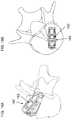
- FIG. 1Ais an isometric view of an expandable implant, constructed and operative according to an embodiment of the present invention, shown in an expanded state;
- FIG. 1Bis a cut-away isometric view similar to FIG. 1A cut along a central longitudinal plane;
- FIGS. 2A and 2Bare side views of the implant of FIG. 1A shown in an initial closed state and an expanded state, respectively;
- FIG. 3is an exploded isometric view of the implant of FIG. 1A additionally showing a tip of a worm-gear tool for actuating expansion of the implant;
- FIGS. 4A and 4Bare cross-sectional views taken along a central longitudinal plane through the implant of FIG. 1A , the implant being shown with the worm-gear tool inserted, with the implant shown in its initial closed state and its expanded state, respectively;
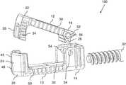
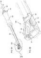
- FIG. 5Ais an isometric view of the implant of FIG. 1A attached to a delivery system
- FIG. 5Bis an enlarged view of the region of FIG. 5A designated V;
- FIGS. 6A-6Care schematic plan views showing the positioning of the implant of FIG. 1A relative to a vertebra during deployment as a laterally-expandable intervertebral cage, the implant being shown in an initial compact state connected to a delivery system, in an expanded deployed state, and after filling and removal of the delivery system, respectively;
- FIGS. 7A and 7Bare side views of a variant implementation of the implant of FIG. 1A , shown in an initial closed state and an expanded state, respectively;
- FIG. 8Ais an isometric view of an expandable implant, constructed and operative according to a further embodiment of the present invention, shown in an expanded state;
- FIG. 8Bis a cut-away isometric view similar to FIG. 8A cut along a central longitudinal plane;
- FIGS. 9A and 9Bare side views of the implant of FIG. 8A shown in an initial closed state and an expanded state, respectively;
- FIG. 10Ais an isometric view of an expandable implant, constructed and operative according to a further embodiment of the present invention, shown in an expanded state;
- FIG. 10Bis a cut-away isometric view similar to FIG. 10A cut along a central longitudinal plane;
- FIGS. 11A and 11Bare side views of the implant of FIG. 10A shown in an initial closed state and an expanded state, respectively;
- FIG. 11Cis a bottom isometric view of the implant of FIG. 10A ;
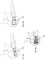
- FIGS. 12A and 12Bare schematic plan views showing the positioning of the implant of FIG. 10A relative to a vertebra in an initial compact state and in an expanded deployed state, respectively;
- FIG. 13Ais an isometric view of an expandable implant, constructed and operative according to a further embodiment of the present invention, shown in an expanded state;
- FIG. 13Bis a cross-sectional view taken along a central longitudinal plane of FIG. 13A ;
- FIGS. 14A and 14Bare side views of the implant of FIG. 13A shown in an initial closed state and an expanded state, respectively;
- FIGS. 15A and 15Bare schematic plan views showing the positioning of the implant of FIG. 13A relative to a vertebra in an expanded deployed state, the implant being shown in a first orientation and a second orientation, respectively;
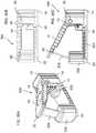
- FIGS. 16A and 16Bare side views of an expandable implant, constructed and operative according to a further embodiment of the present invention, shown in an initial closed state and an expanded state, respectively;
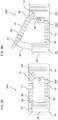
- FIGS. 16C and 16Dare cross-sectional views taken along a central longitudinal plane of FIGS. 16A and 16B , respectively;
- FIGS. 17A and 17Bare isometric views of the expandable implant of FIGS. 16A and 16B , respectively;
- FIGS. 18A and 18Bare schematic isometric and plan views, respectively, showing positioning of an expandable implant relative to a vertebra in an expanded deployed state according to a variant embodiment for adjusting lordotic angle between vertebral bodies when inserted via a TLIF approach;
- FIGS. 19A and 19Bare schematic lateral and anterior views, respectively, showing positioning of the expandable implant of FIGS. 18A and 18B relative to a vertebra in an expanded deployed state when inserted via a PLIF approach;
- FIG. 20is an isometric view of an expandable implant, constructed and operative according to a further embodiment of the present invention, shown in an expanded state;
- FIGS. 20B and 20Care side views of the implant of FIG. 20A shown in an initial closed state and an expanded state, respectively;
- FIGS. 21A and 21Bare cross-sectional view taken along a central longitudinal plane of FIG. 20A in an initial closed state and an expanded state, respectively.
- the present inventionis an expandable implant.
- FIGS. 1A-6Ca first embodiment illustrated in FIGS. 1A-6C
- FIGS. 8A-9Ba second embodiment illustrated in FIGS. 8A-9B
- FIGS. 10A-12Ba third embodiment illustrated in FIGS. 10A-12B
- FIGS. 13A-15Ba fourth embodiment illustrated in FIGS. 13A-15B .
- the remaining figuresrelate to a number of variant implementations and alternative embodiments that will be addressed separately below.
- the expandable implantincludes a base 10 and a displaceable element 12 .
- a first end portion 14 of base 10is hingedly interconnected to a first end portion 16 of displaceable element 12 so as to be pivotable about an axis 18 .
- Second end portions 20 and 22 of base 10 and displaceable element 12are formed with complementary jaws 24 and 26 , respectively.
- the complementary jawsare configured to provide continuous overlap over a range of angular positions of the displaceable element relative to the base.
- the particular range of angular positions accommodated by the implant while maintaining overlapdepends upon the intended application, as will be discussed further below, but in most cases will be in excess of 10 degrees, and in many cases in excess of 20 degrees.
- the present inventionrelates to an “implant”.
- implantis used herein in the description and claims to refer to any implant useful for introducing into a human or animal body, particularly as part of an orthopedic surgical procedure.
- the inventionwill be exemplified herein with reference specifically to the field of spinal surgery, and in particular, in applications in which the implant is deployed in the intervertebral space.
- the implant of the present inventionis not limited to such applications, and may find utility in a range of other spinal and non-spinal procedures.
- expandable implantrefers to an implant which can be expanded once within the body so as to increase its external dimensions in at least one direction.
- an “enclosed volume”refers to a volume which lies within a closed loop formed by an implant, preferably so that the volume is encompassed on all sides sufficiently to form a barrier tending to prevent, or at least limit, dispersion of various types of filling material.
- the enclosureis typically a two-dimensional enclosure, meaning that the volume defined by the implant is effectively enclosed in a plane of a loop formed by the implant, but is open in a direction perpendicular to that plane. In applications in which the implant is deployed between inward-facing tissue surfaces, those tissue surfaces together with the structure of the implant cooperate to define a three-dimensional enclosure.
- the term “enclosed”does not rule out the presence of one or more openings or windows formed through one or more elements of the enclosing structure, which may for example define a preferred direction of controlled release of excess filling material for applications where such overflow is appropriate. Furthermore, the enclosing structure does not necessarily have a uniform wall height around the entire enclosure, and is still considered to “enclose” the volume so long as it is sufficient to limit dispersion of the filling material.
- jaws 24 and 26are referred to variously as providing “complementary facing arcuate surfaces” or “complementary facing surfaces corresponding to solids of revolution about axis 18 ”. These phrases refer to various geometries of facing surfaces that allow the surfaces to maintain close proximity over a range of pivotal motion between base 10 and displaceable element 12 .
- the surfacespreferably approximate closely to an “arcuate contact profile” shaped to maintain sliding contact as the two elements move through relative pivotal motion.
- the elementsare typically designed to have a small clearance, preferably of less than 1 millimeter, and typically of no more than 0.5 millimeter.
- the facing surfacesmay be in various forms, including, but not limited to, partial-cylindrical surfaces centered on axis 18 and/or planar surfaces perpendicular to axis 18 .
- Other forms of contact surfacemay also be used where the contact surfaces are parts of a male-female pair of solids of revolution about axis 18 .
- a number of different exampleswill be shown in the examples below, and unless otherwise stated, are interchangeable between the various disclosed embodiments. It should also be noted that any reference to “abutment” between the surfaces does not require that contact occurs in the unstressed state of the implant, but rather that the corresponding facing surfaces maintain facing overlap over the range of motion.
- the implants of the present inventionmay be implemented using any biocompatible material with suitable mechanical properties, including but not limited to various polymer materials, such as PEEK, ceramic materials, and various metals and metal alloys. Certain particularly preferred implementations are formed primarily, or exclusively, from titanium, which combines mechanical strength with good bone integration properties.
- an opening mechanism employed to expand the implant within the bodyis based on the principle of a worm gear engagement. Accordingly, in such embodiments, first end portion 16 of displaceable element 12 is formed with a plurality of projecting teeth 28 configured as a partial gear centered on axis 18 . Projecting teeth 28 are configured for engaging a complementary worm gear.
- first end portion 14 of base 10is formed with a socket 30 ( FIG. 1B ) configured for removably receiving a worm gear tool 32 ( FIGS. 3, 4A and 4B ) which engages teeth 28 in order to actuate expansion of the implant.
- a locking or retention mechanismis preferably provided.
- a locking mechanismcan be implemented in various ways.
- One particularly simple locking mechanismis the use of a tightenable clamping screw (not shown) mounted in first end portion 14 which bears on end portion 16 in the region of the pivotal connection and locks the desired relative positions of base 10 and displaceable element 12 .
- a tightenable clamping screw(not shown) mounted in first end portion 14 which bears on end portion 16 in the region of the pivotal connection and locks the desired relative positions of base 10 and displaceable element 12 .
- complementary jaws 24 and 26are formed with complementary parts of a retention configuration configured for inhibiting return of displaceable element 12 after expansion towards an initial closed position.
- the retention configurationis implemented as at least one sequence of ratchet teeth 34 , here shown as part of jaws 26 , that are deployed to inhibit return of the displaceable element from a range of positions of the displaceable element towards the initial position by engaging a facing lip 36 of jaws 24 ( FIG. 1A ).
- ratchet teeth 34 and facing lip 36are deployed on surfaces which are generally perpendicular to axis 18 .
- load applied to the cage as a result of the normal axial loading between vertebraetends to enhance locking of the ratchet engagement.
- jaw 26is implemented as a pair of projecting portions that are interposed between inward facing surfaces of jaw 24 .
- Jaw 26could also be implemented as a single contiguous block (as in implant 200 below), except that it is desired to leave a central void to provide access for a ratchet release tool, as further detailed below.
- jaw 24is here implemented with an integrated end wall such that the inward facing surfaces and the end wall encompass the projecting portions of jaw 26 on three sides.
- the entire form of the distal tip of the implantis defined by second end portion 20 of base 10 , while second end portion 22 of displaceable element 12 is essentially contained within end portion 20 .
- This optionmay in some cases be advantageous as reducing interaction between the moveable element 12 and surrounding tissue during deployment, thereby minimizing frictional resistance to opening of the implant.
- the hinged interconnection between base 10 and displaceable element 12may be implemented using any suitable hinge engagement configuration.
- the engagement configurationis formed by pins 52 projecting bilaterally from the sides of first end portion 16 of the displaceable element which engage complementary sockets or apertures 54 in side walls of first end portion 14 of the base.
- pins 52may be formed with a chamfer 56 which helps to momentarily flex apart the sides of the base during assembly.
- a reversed configuration, in which pins projecting from the base engage recesses or a bore in the displaceable elementmay also be used.
- a separate hinge pinmay be used.
- implant 100The process of deployment of implant 100 will thus be understood as follows. With the implant in its initial closed state, it is attached to a hollow shaft 38 of a delivery system 40 via a suitable releasable gripping mechanism (not detailed here). Worm gear tool 32 is inserted through delivery system 40 and its handle 42 turned until the worm engages teeth 28 and advances to its fully inserted position, as illustrated in FIG. 4A . A locking mechanism 44 is then engaged to lock worm gear tool 32 against longitudinal motion relative to delivery system 40 . Insertion of tool 32 can be performed either before or after insertion of the implant into the body.
- Implant 100is introduced via a suitable incision, after any required preparatory steps have been performed as is known in the art, so that the base is correctly positioned in the target location.
- Handle 42is then rotated in a direction reversed relative to its insertion direction. Since worm gear tool 32 is locked by locking mechanism 44 , the worm gear is unable to retract from the insert, and instead pushes against teeth 28 , thereby forcing displaceable element 12 to rotate around axis 18 , successively passing one after another of ratchet teeth 34 over lip 36 .
- worm gear tool 32 and teeth 28may be configured with a left-handed threading direction, if a clockwise rotation is preferred as a more intuitive motion for expanding the implant.
- handle 42is preferably turned slightly in the reverse direction, to remove loading from the worm gear.
- Locking mechanism 44is then released, and worm gear tool 32 can be rotated until it disengages from teeth 28 and can be completely removed from the delivery system.
- FIGS. 6A and 6Billustrate the stages of operation as described above for a TLIF approach
- FIG. 6Cillustrates the final deployed implant after filling and removal of the delivery system.
- jaw 24is formed with a central slot 46 , optionally intersecting with an additional aperture 48 , which subdivides jaw 24 into two separate resilient elements, each bearing one of the ratchet-engaging lips 36 .
- a suitable prising toolsuch as a screw-driver tip (not shown) into slot 46 , it is possible to increase a spacing of the slot, moving lips 36 apart sufficiently to release the ratchet engagement and allow displacement of displaceable element 12 towards its initial position.
- expandable implant 100typically consists essentially of only two primary structural components: base 10 and displaceable element 12 , optionally with an additional hinge pin depending upon the chosen design for the hinge.
- base 10and displaceable element 12
- additional hinge pindepending upon the chosen design for the hinge.
- Expandable implant 100 as illustrated hereis particularly adapted for use as an intervertebral cage which expands laterally, i.e., within the intervertebral disc space, as part of an intervertebral fusion procedure.
- the leading end of second end portion 20is here rounded to provide a “bullet nose” effect known to be advantageous for facilitating insertion and minimizing trauma to surrounding tissue during introduction of the device into the body.
- Expandable implant 100also features lateral ridges 50 or other projecting features on the edges of base 10 and displaceable element 12 configured to enhance gripping of the adjacent vertebral endplates when the device is deployed.
- Implant 150is essentially similar in structure and function to implant 100 , but differs in that the closed configuration of FIG. 7A is formed with a negative angle between the outer surfaces of base 10 and displaceable element 12 , i.e., so that it converges towards end portions 20 and 22 , which here form the distal end of the implant.
- the resulting wedge shapemay facilitate introduction of the implant into the body, gradually forcing apart the adjacent tissue.
- the implantis expanded to the desired extent, in the same manner discussed above in relation to implant 100 .
- each of the implants discussed hereinmay be implemented with an initial closed state which has parallel, negatively angled, or positively angled outer surfaces.
- Implant 200differs from implant 100 primarily in that it is implemented using a worm gear 202 which remains within the body as part of the implant itself.
- Worm gear 202is rotatably deployed in a recess 204 within first end portion 14 so as to engage teeth 28 .
- Rotation of worm gear 202displaces teeth 28 so as to rotate the partial gear about axis 18 , thereby effecting displacement of the displaceable element from the initial closed state of FIG. 9A to the any desired position in the range up to the fully open state of FIG. 9B .
- a driver-receiving socket 206in this case a hex-socket, is formed in at least a proximal end of worm gear 202 so as to allow driving engagement of a suitable driver tool (not shown) with the worm gear.
- the pitch angle of worm gear 202is preferably chosen so as to provide effective frictional locking of the expandable implant at all points within its range of motion, such that no separate ratchet arrangement or other retention mechanism is typically required.
- the presence of the worm gear as a part of the implantraises the typical count of main structural components of the implant to three, but the structure remains strikingly simple, reliable and compact.
- worm gear 202is most preferably here implemented as a hollow worm gear formed with an axial through-bore 208 .
- a driver tool(replacing worm gear tool 42 of that figure) is used to rotate worm gear 202 to achieve a desired degree of expansion. Once the desired expansion has been achieved, the driver tool is removed, leaving the delivery system lumen available and aligned with through-bore 208 for introduction of filling material via the axial through-bore into the expandable implant.
- expandable implant 200is similar to that of expandable implant 100 , and will be understood by analogy to the above description.
- Implant 300differs from implant 200 primarily in that it is implemented with a worm gear deployment mechanism at its distal end rather than its proximal end.
- expandable implant 300includes a worm gear 302 rotatably deployed in a recess 304 within first end portion 14 so as to engage teeth 28 .
- Rotation of worm gear 302displaces teeth 28 so as to rotate the partial gear about axis 18 , thereby effecting displacement of the displaceable element from the initial closed state of FIG. 11A to the any desired position in the range up to the fully open state of FIG. 11B .
- a driver-receiving socket 306is formed in the inward-facing end of worm gear 302 , and is complemented by an aperture 308 formed in the second end portion 20 of the base and aligned with driver-receiving socket 306 so as to allow driving engagement of a suitable driver tool (not shown) with worm gear 302 .
- jaw 26is here implemented as a forked element with a central gap aligned with aperture 308 , as in implant 100 above.
- Positioning of the deployment mechanism at the distal end of implant 300generates a deployment geometry with expansion occurring primarily at the proximal end of the implant when deployed, in contrast to the primarily distal expansion of FIGS. 6B and 6C .
- a typical position of deployment of implant 300 via a TLIF approach, prior to and after expansion,is shown schematically in FIGS. 12A and 12B , respectively.
- first end portion 14 of base 10that forms the leading (distal) end of the implant during insertion.
- First end portion 14is therefore preferably formed with a rounded or “bullet-nose” profile, as best seen in FIG. 11C , in order to facilitate the insertion.
- expandable implant 300is similar to that of expandable implant 200 , and will be understood by analogy to the above description.
- implant 400illustrated in FIGS. 13A-15B , this implant is conceptually a combination of features from implants 200 and 300 , with analogous features labeled similarly.
- Implant 400differs from implants 200 and 300 primarily in that it provides accessibility for operating worm gear 202 from either end of the implant, thereby allowing the user to choose whether to deploy the implant with the worm gear mechanism at the proximal or distal end of the implant.
- expandable implant 400shares with implant 200 a worm gear 202 deployed in a recess 204 with a through-bore 208 which typically is implemented with a hex-socket cross-section so as to serve also as a bidirectional driver-receiving socket.
- second end portion 20 of the baseis preferably formed with an aperture 308 aligned with worm gear 202 so as to allow insertion of a tool through the aperture to engage the worm gear for rotating the worm gear.
- FIG. 15Aillustrates schematically a deployed position of expandable implant 400 relative to a vertebral endplate via a TLIF approach when the worm gear mechanism is deployed proximally so as to expand primarily at its distal end.
- FIG. 15Billustrates schematically a deployed position of expandable implant 400 relative to a vertebral endplate via a TLIF approach when the worm gear mechanism is deployed distally so as to expand primarily at its proximal end.
- Expandable implant 400also illustrates a further variant implementation of overlapping jaws 24 and 26 .
- jaw 26is here implemented a structure which extends the full width of the implant, with a forked structure which straddles a connecting region 402 of base 10 , as best seen in FIG. 13A .
- jaw 24is implemented as an end plate with an arcuate inside surface in facing relation to the arcuate outer surface of jaw 26 .
- expandable implant 400is similar to that of expandable implants 200 and 300 , and will be understood by analogy to the preceding description.
- FIGS. 16A-17Bthese illustrate a variant implementation of expandable implant 200 , designated expandable implant 250 .
- Implant 250is essentially similar in structure and function to implant 200 , with analogous elements labeled similarly.
- Implant 250differs from implant 200 primarily in the structure of jaws 24 and 26 , which are here arranged as arcuate nested elements with jaw 26 closer to axis 18 and jaw 24 further from the axis. This arrangement allows both jaws to extend across the entire width of the implant. In certain cases, this configuration may provide advantages when used as a laterally expandable intervertebral cage if it is desired to provide enhanced support of around the entire periphery of the cage when deployed.
- the width dimension of implants according to the present inventionmay be varied according to the needs of each particular application.
- FIGS. 18A-19Balthough illustrated thus far in the exemplary context of an implant expanding laterally, within an axial plane, it should be noted that the implants of the present invention are not limited to this application, and can equally be used for a range of additional orthopedic applications, whether in spinal surgery or elsewhere in the body.
- FIGS. 18A-19Billustrate a modified version of implant 100 , here designated 160 , configured for use as an angle-correcting implant for adjusting a lordotic angle and/or a scoliosis angle between adjacent vertebral endplates.
- FIGS. 18A and 18Billustrate deployment of expandable implant for restoration of lordotic angle via a TLIF approach
- FIGS. 19A and 19Billustrate deployment via a PLIF approach.
- angular range of motion for which each of the above examples is designedvaries according to the requirements of each application.
- angular ranges of up to 8 degreesmay be sufficient.
- a maximum opening angle in the range of 20-30 degreesmay be preferred.
- an expandable implantgenerally designated 500 which exemplifies an alternative approach to maintaining an enclosed volume within the implant during angular deployment of a displaceable element 12 relative to a base 10 .
- the features of implant 500are generally similar to those of implant 200 described above, and analogous features are labelled similarly.
- second end portion 20 of base 10is formed with a hollow block 502 that houses a channel 504 within which is housed a flexible strip 506 .
- One end of flexible strip 506is fastened to second end portion 22 of displaceable element 12 so that the strip is drawn out and deployed as displaceable element 12 opens away from base 10 .
- a mechanism(not shown) may be deployed to maintain tension in the strip.
Landscapes
- Health & Medical Sciences (AREA)
- Engineering & Computer Science (AREA)
- Biomedical Technology (AREA)
- Orthopedic Medicine & Surgery (AREA)
- Neurology (AREA)
- Transplantation (AREA)
- Heart & Thoracic Surgery (AREA)
- Oral & Maxillofacial Surgery (AREA)
- Cardiology (AREA)
- Vascular Medicine (AREA)
- Life Sciences & Earth Sciences (AREA)
- Animal Behavior & Ethology (AREA)
- General Health & Medical Sciences (AREA)
- Public Health (AREA)
- Veterinary Medicine (AREA)
- Physical Education & Sports Medicine (AREA)
- Prostheses (AREA)
Abstract
Description
Claims (20)
Priority Applications (1)
| Application Number | Priority Date | Filing Date | Title |
|---|---|---|---|
| US16/322,019US10786367B2 (en) | 2016-07-21 | 2017-07-23 | Expandable implant |
Applications Claiming Priority (3)
| Application Number | Priority Date | Filing Date | Title |
|---|---|---|---|
| US201662364885P | 2016-07-21 | 2016-07-21 | |
| PCT/IL2017/050828WO2018015964A1 (en) | 2016-07-21 | 2017-07-23 | Expandable implant |
| US16/322,019US10786367B2 (en) | 2016-07-21 | 2017-07-23 | Expandable implant |
Related Parent Applications (1)
| Application Number | Title | Priority Date | Filing Date |
|---|---|---|---|
| PCT/IL2017/050828A-371-Of-InternationalWO2018015964A1 (en) | 2016-07-21 | 2017-07-23 | Expandable implant |
Related Child Applications (1)
| Application Number | Title | Priority Date | Filing Date |
|---|---|---|---|
| US17/035,301ContinuationUS11806248B2 (en) | 2016-07-21 | 2020-09-28 | Expandable implant |
Publications (2)
| Publication Number | Publication Date |
|---|---|
| US20190175357A1 US20190175357A1 (en) | 2019-06-13 |
| US10786367B2true US10786367B2 (en) | 2020-09-29 |
Family
ID=60992268
Family Applications (2)
| Application Number | Title | Priority Date | Filing Date |
|---|---|---|---|
| US16/322,019ActiveUS10786367B2 (en) | 2016-07-21 | 2017-07-23 | Expandable implant |
| US17/035,301Active2038-07-31US11806248B2 (en) | 2016-07-21 | 2020-09-28 | Expandable implant |
Family Applications After (1)
| Application Number | Title | Priority Date | Filing Date |
|---|---|---|---|
| US17/035,301Active2038-07-31US11806248B2 (en) | 2016-07-21 | 2020-09-28 | Expandable implant |
Country Status (3)
| Country | Link |
|---|---|
| US (2) | US10786367B2 (en) |
| EP (1) | EP3487448B1 (en) |
| WO (1) | WO2018015964A1 (en) |
Cited By (3)
| Publication number | Priority date | Publication date | Assignee | Title |
|---|---|---|---|---|
| US20210077271A1 (en)* | 2016-07-21 | 2021-03-18 | Seaspine, Inc. | Expandable Implant |
| US11399959B2 (en)* | 2020-05-22 | 2022-08-02 | Hilo Innovations, Llc | Expandable lumbar cage and method for inserting the same |
| US12318307B2 (en) | 2021-07-16 | 2025-06-03 | Blue Ocean Spine Gmbh | Adjustable spinal implants, associated instruments and methods |
Families Citing this family (19)
| Publication number | Priority date | Publication date | Assignee | Title |
|---|---|---|---|---|
| US9220547B2 (en) | 2009-03-27 | 2015-12-29 | Spinal Elements, Inc. | Flanged interbody fusion device |
| US9545283B2 (en)* | 2013-12-23 | 2017-01-17 | Jmea Corporation | Devices and methods for preparation of vertebral members |
| US11219532B2 (en)* | 2017-09-18 | 2022-01-11 | Loubert S. Suddaby | Stand-alone expandable interbody spinal fusion device with locking mechanism |
| US11806250B2 (en) | 2018-02-22 | 2023-11-07 | Warsaw Orthopedic, Inc. | Expandable spinal implant system and method of using same |
| AU2019342137A1 (en) | 2018-09-20 | 2021-03-25 | Spinal Elements, Inc. | Spinal implant device |
| US12121453B2 (en) | 2020-11-05 | 2024-10-22 | Warsaw Orthopedic, Inc. | Dual wedge expandable implant with eyelets, system, and method of use |
| US11517363B2 (en) | 2020-11-05 | 2022-12-06 | Warsaw Orthopedic, Inc. | Screw driver and complimentary screws |
| US11638653B2 (en) | 2020-11-05 | 2023-05-02 | Warsaw Orthopedic, Inc. | Surgery instruments with a movable handle |
| US11517443B2 (en) | 2020-11-05 | 2022-12-06 | Warsaw Orthopedic, Inc. | Dual wedge expandable implant, system and method of use |
| US12318308B2 (en) | 2020-11-05 | 2025-06-03 | Warsaw Orthopedic, Inc. | Dual expandable inter-body device |
| US11833059B2 (en) | 2020-11-05 | 2023-12-05 | Warsaw Orthopedic, Inc. | Expandable inter-body device, expandable plate system, and associated methods |
| US12239544B2 (en) | 2020-11-05 | 2025-03-04 | Warsaw Orthopedic, Inc. | Rhomboid shaped implants |
| US12171439B2 (en) | 2020-11-05 | 2024-12-24 | Warsaw Orthopedic, Inc. | Protected drill |
| US11963881B2 (en) | 2020-11-05 | 2024-04-23 | Warsaw Orthopedic, Inc. | Expandable inter-body device, system, and method |
| US11911284B2 (en) | 2020-11-19 | 2024-02-27 | Spinal Elements, Inc. | Curved expandable interbody devices and deployment tools |
| WO2022133456A1 (en) | 2020-12-17 | 2022-06-23 | Spinal Elements, Inc. | Spinal implant device |
| US11612499B2 (en) | 2021-06-24 | 2023-03-28 | Warsaw Orthopedic, Inc. | Expandable interbody implant |
| WO2022271280A1 (en)* | 2021-06-24 | 2022-12-29 | Warsaw Orthopedic, Inc. | Expandable interbody implant and corresponding surgical tool |
| US12295865B2 (en) | 2021-06-24 | 2025-05-13 | Warsaw Orthopedic, Inc. | Expandable interbody implant and corresponding inserter |
Citations (120)
| Publication number | Priority date | Publication date | Assignee | Title |
|---|---|---|---|---|
| US5554191A (en)* | 1994-01-26 | 1996-09-10 | Biomat | Intersomatic vertebral cage |
| US6159244A (en)* | 1999-07-30 | 2000-12-12 | Suddaby; Loubert | Expandable variable angle intervertebral fusion implant |
| US6436140B1 (en)* | 1998-08-28 | 2002-08-20 | Sofamor S.N.C. | Expandable interbody fusion cage and method for insertion |
| US6443989B1 (en)* | 2000-12-04 | 2002-09-03 | Roger P. Jackson | Posterior expandable fusion cage |
| US20020128713A1 (en)* | 1999-08-13 | 2002-09-12 | Bret Ferree | Spinal fusion cage with lordosis correction |
| US20030208275A1 (en)* | 2000-02-04 | 2003-11-06 | Michelson Gary K. | Expandable push-in interbody spinal fusion implant |
| US6685742B1 (en)* | 2002-11-12 | 2004-02-03 | Roger P. Jackson | Articulated anterior expandable spinal fusion cage system |
| US20040044411A1 (en) | 2002-08-30 | 2004-03-04 | Loubert Suddaby | Lordotic fusion implant |
| US20040127994A1 (en)* | 2002-10-16 | 2004-07-01 | Erich Kast | Implant for placement between vertebrae |
| US20040162618A1 (en)* | 2003-02-14 | 2004-08-19 | Centerpulse Spine-Tech, Inc. | Expandable intervertebral implant cage |
| US20050113916A1 (en)* | 2003-11-21 | 2005-05-26 | Branch Charles L.Jr. | Expandable spinal implant |
| US6962606B2 (en)* | 2000-02-04 | 2005-11-08 | Gary Karlin Michelson | Expandable push-in interbody spinal fusion implant |
| US20060030943A1 (en)* | 2004-07-23 | 2006-02-09 | Marc Peterman | Expandable spinal implant having interlocking geometry for structural support |
| US20060206207A1 (en)* | 2005-01-20 | 2006-09-14 | Dryer Randall F | Expandable spinal fusion cage and associated instrumentation |
| US7641690B2 (en)* | 2004-08-23 | 2010-01-05 | Abdou M Samy | Bone fixation and fusion device |
| US7763028B2 (en)* | 2004-02-13 | 2010-07-27 | Warsaw Orthopedic, Inc. | Spacer with height and angle adjustments for spacing vertebral members |
| US20110172774A1 (en)* | 2010-01-11 | 2011-07-14 | Armando Varela | Expandable intervertebral implant and associated surgical method |
| US20120029637A1 (en)* | 2010-08-02 | 2012-02-02 | Ragab Ashraf A | Rotatable Cam Lift for an Expandable Bone Cage |
| US20120029636A1 (en)* | 2010-08-02 | 2012-02-02 | Ragab Ashraf A | Bone Cage with Components for Controlled Expansion |
| US8187332B2 (en)* | 2004-11-03 | 2012-05-29 | Mcluen Design, Inc. | Bone fusion device |
| US20120185049A1 (en)* | 2010-01-11 | 2012-07-19 | Innova Spinal Technologies, Llc | Expandable intervertebral implant and associated surgical method |
| US20120271422A1 (en)* | 2011-04-19 | 2012-10-25 | Warsaw Orthopedic, Inc. | Expandable implant system and methods of use |
| US20130041471A1 (en)* | 2011-07-14 | 2013-02-14 | Nlt Spine Ltd. | Laterally Deflectable Implant |
| US20130079883A1 (en)* | 2007-03-29 | 2013-03-28 | Life Spine, Inc. | Radially expandable spinal interbody device and implantation tool |
| US20130158664A1 (en)* | 2011-12-19 | 2013-06-20 | Warsaw Orthopedic, Inc. | Expandable interbody implant and methods of use |
| US8486149B2 (en)* | 2011-02-23 | 2013-07-16 | DePuy Synthes Products, LLC | Expandable interbody fusion implant |
| US20130274883A1 (en)* | 2012-04-13 | 2013-10-17 | Gary R. McLuen | Bone fusion device |
| US20140114420A1 (en)* | 2012-10-24 | 2014-04-24 | James C. Robinson | Expandable inter-body fusion devices and methods |
| US20140188224A1 (en)* | 2012-12-14 | 2014-07-03 | Facet-Link Inc. | Laterally expandable intervertebral fusion implant |
| US20140249629A1 (en)* | 2005-04-12 | 2014-09-04 | Ahmnon D. Moskowitz | Zero-profile expandable intervertebral spacer devices for distraction and spinal fusion and a universal tool for their placement and expansion |
| US20140277508A1 (en)* | 2013-03-15 | 2014-09-18 | Atlas Spine, Inc. | Plif hinged spacer |
| US20140288653A1 (en)* | 2013-03-20 | 2014-09-25 | Kuei Jung CHEN | Textured implant device having series extendible blades |
| US20140309741A1 (en)* | 2013-03-15 | 2014-10-16 | Paradigm Spine, Llc | Modular, customizable spine stabilization system |
| US20140343678A1 (en)* | 2013-05-20 | 2014-11-20 | K2M, Inc. | Adjustable Implant and Insertion Tool |
| US20150012098A1 (en)* | 2013-07-03 | 2015-01-08 | Spine Innovation, Inc. | Methods and apparatus for implanting an interbody device |
| US20150057755A1 (en)* | 2013-08-21 | 2015-02-26 | K2M, Inc. | Expandable spinal implant |
| US20150066145A1 (en)* | 2013-08-29 | 2015-03-05 | Andrew Rogers | Expandable and adjustable lordosis interbody fusion system |
| US20150148908A1 (en)* | 2012-05-18 | 2015-05-28 | Trinity Orthopedics,. LLC | Articulating Interbody Cage and Methods Thereof |
| WO2015087285A1 (en) | 2013-12-11 | 2015-06-18 | Nlt Spine Ltd. | Worm-gear actuated orthopedic implants & methods |
| US20150223945A1 (en)* | 2014-02-07 | 2015-08-13 | Globus Medical, Inc | Variable Lordosis Spacer and Related Methods of Use |
| US20150223946A1 (en)* | 2014-02-07 | 2015-08-13 | Globus Medical, Inc. | Variable lordosis spacer and related methods of use |
| US20150351925A1 (en)* | 2013-01-24 | 2015-12-10 | Biomet Spine, Llc | Adjustable interbody fusion device and method of use |
| US20160015522A1 (en)* | 2014-07-15 | 2016-01-21 | Uri Arnin | Spinal cage |
| US20160022434A1 (en)* | 2012-08-08 | 2016-01-28 | James C. Robinson | Expandable intervertebral cage assemblies |
| US20160030190A1 (en)* | 2012-08-08 | 2016-02-04 | James C. Robinson | Expandable intervertebral cage assemblies |
| US20160038305A1 (en)* | 2014-02-07 | 2016-02-11 | Globus Medical, Inc. | Variable lordosis spacer and related methods of use |
| US9278008B2 (en) | 2012-05-30 | 2016-03-08 | Globus Medical, Inc. | Expandable interbody spacer |
| US20160089247A1 (en)* | 2013-05-13 | 2016-03-31 | Biomet Spine, Llc | Adjustable interbody fusion devices |
| US20160100951A1 (en)* | 2014-10-09 | 2016-04-14 | K2M, Inc. | Expandable spinal interbody spacer and method of use |
| US20160113776A1 (en)* | 2014-10-27 | 2016-04-28 | Warsaw Orthopedic, Inc. | Spinal implant system and method |
| US20160166396A1 (en)* | 2014-12-11 | 2016-06-16 | K2M, Inc. | Expandable spinal implants |
| US20160206440A1 (en)* | 2015-01-21 | 2016-07-21 | Warsaw Orthopedic, Inc. | Unitarily formed expandable spinal implant and method of manufacturing and implanting same |
| US20160250034A1 (en)* | 2013-10-31 | 2016-09-01 | Nlt Spine Ltd. | Adjustable implant |
| US9439771B2 (en)* | 2011-10-19 | 2016-09-13 | P&H Medical Products, Llc | Laterally expandable spinal prosthesis |
| US9498347B2 (en)* | 2014-06-25 | 2016-11-22 | Spine Wave, Inc. | Expandable interbody fusion device with nested correction surface |
| US20160338846A1 (en)* | 2015-05-18 | 2016-11-24 | Zavation, Llc | Method and system of installing a spinal fusion cage |
| US20160354211A1 (en)* | 2011-10-19 | 2016-12-08 | P&H Medical Products, Llc | Laterally expandable spinal prosthesis |
| US20170042695A1 (en)* | 2015-08-12 | 2017-02-16 | Warsaw Orthopedic, Inc. | Expandable spinal implant and method of implanting same |
| US20170100255A1 (en)* | 2015-04-16 | 2017-04-13 | Expanding Orthopedics Inc. | Intervertebral cage for lateral approach |
| US20170105844A1 (en)* | 2015-10-16 | 2017-04-20 | Warsaw Orthopedic, Inc. | Expandable spinal implant system and method |
| US20170112631A1 (en)* | 2015-10-26 | 2017-04-27 | Warsaw Orthopedic, Inc. | Spinal implant system and method |
| US20170119538A1 (en)* | 2015-09-10 | 2017-05-04 | Atlas Spine, Inc. | Expandable spinal fusion device |
| US20170128228A1 (en)* | 2009-03-13 | 2017-05-11 | The University Of Toledo | Minimally Invasive Collapsible Cage |
| US20170151066A1 (en)* | 2009-05-06 | 2017-06-01 | Stryker European Holdings I, Llc | Expandable spinal implant apparatus and method of use |
| US20170156885A1 (en)* | 2014-06-25 | 2017-06-08 | Nlt Spine Ltd. | Expanding implant with hinged arms |
| US20170172758A1 (en)* | 2015-12-21 | 2017-06-22 | Southern Spine, Llc | Expandable Interbody Devices and Related Instruments and Methods for Spinal Fusion Surgery |
| US20170181863A1 (en)* | 2015-12-28 | 2017-06-29 | Spineology Inc. | Expandable interbody device |
| US20170189200A1 (en)* | 2016-01-04 | 2017-07-06 | Warsaw Orthopedic, Inc | Pivoting wedge expanding spinal implant and method of implanting same |
| US20170209282A1 (en)* | 2014-08-01 | 2017-07-27 | H. Lee Moffitt Cancer Center And Research Institute, Inc. | Expandable intervertebral cage |
| US20170216045A1 (en)* | 2016-01-28 | 2017-08-03 | Warsaw Orthopedic, Inc | Geared cam expandable interbody implant and method of implanting same |
| US20170231780A1 (en)* | 2014-08-05 | 2017-08-17 | Paul S. D'Urso | Expandable fusion cage |
| US20170246006A1 (en)* | 2016-02-26 | 2017-08-31 | K2M, Inc. | Insertion instrument for expandable spinal implants |
| US20170296352A1 (en)* | 2014-09-30 | 2017-10-19 | Yellowsteps | Interbody fusion cage with adjustable cover, and related manufacture method |
| US9795493B1 (en)* | 2013-03-15 | 2017-10-24 | Nuvasive, Inc. | Expandable intervertebral implant and methods of use thereof |
| US20170304071A1 (en)* | 2016-04-25 | 2017-10-26 | Craig Black | Expandable Spinal Cages |
| US9801734B1 (en)* | 2013-08-09 | 2017-10-31 | Nuvasive, Inc. | Lordotic expandable interbody implant |
| US20170312090A1 (en)* | 2014-10-21 | 2017-11-02 | Nlt Spine Ltd. | Adjustable implant |
| US20170312092A1 (en)* | 2014-10-31 | 2017-11-02 | Facet-Link Inc. | Fully expandable intervertebral fusion implant with traveller |
| US20170319352A1 (en)* | 2016-05-05 | 2017-11-09 | Warsaw Orthopedic, Inc | Geared cam expandable interbody implant and method of implanting same |
| US20170325967A1 (en)* | 2014-10-31 | 2017-11-16 | Facet-Link Inc. | Fully expandable intervertebral fusion implant |
| US20170333198A1 (en)* | 2014-10-28 | 2017-11-23 | Spectrum Spine Ip Holdings, Llc | Expandable, adjustable inter-body fusion devices and methods |
| US20170333199A1 (en)* | 2016-05-20 | 2017-11-23 | Howmedica Osteonics Corp. | Expandable interbody implant with lordosis correction |
| US20170333200A1 (en)* | 2016-05-19 | 2017-11-23 | Apifix Ltd. | Adjustable spinal cage |
| US20170367842A1 (en)* | 2013-03-13 | 2017-12-28 | Life Spine, Inc. | Expandable implant assembly |
| US20170367845A1 (en)* | 2016-06-28 | 2017-12-28 | Eit Emerging Implant Technologies Gmbh | Expandable and angularly adjustable articulating intervertebral cages |
| US20170367843A1 (en)* | 2016-06-28 | 2017-12-28 | Eit Emerging Implant Technologies Gmbh | Expandable, angularly adjustable intervertebral cages |
| US20180000609A1 (en)* | 2016-06-29 | 2018-01-04 | Globus Medical, Inc. | Expandable fusion device and method of installation thereof |
| US20180000606A1 (en)* | 2016-06-29 | 2018-01-04 | Globus Medical, Inc. | Expandable fusion device and method of installation thereof |
| US20180014947A1 (en)* | 2014-06-03 | 2018-01-18 | Atlas Spine, Inc. | Spinal Implant Device |
| US20180036137A1 (en)* | 2015-03-06 | 2018-02-08 | Spineart Sa | Intervertebral cages and their uses |
| US20180036138A1 (en)* | 2014-10-28 | 2018-02-08 | Spectrum Spine Ip Holdings, Llc | Expandable, adjustable inter-body fusion devices and methods |
| US20180104066A1 (en)* | 2016-10-19 | 2018-04-19 | Imds Llc | Intervertebral cage |
| US20180116815A1 (en)* | 2016-11-01 | 2018-05-03 | Warsaw Orthopedic, Inc. | Expandable spinal implant system with a biased tip and method of using same |
| US9962272B1 (en)* | 2017-06-28 | 2018-05-08 | Amendia, Inc. | Intervertebral implant device with lordotic expansion |
| US20180125671A1 (en)* | 2016-10-27 | 2018-05-10 | Ldr Medical | Expansible Intervertebral Implant |
| US20180147066A1 (en)* | 2016-11-29 | 2018-05-31 | Amendia, Inc. | Intervertebral implant device with independent distal-proximal expansion |
| US20180185164A1 (en)* | 2015-07-14 | 2018-07-05 | Nlt Spine Ltd. | Expandable implant with deflectable sequence of segments |
| US20180193164A1 (en)* | 2017-01-10 | 2018-07-12 | Anza Innovations Inc. | Expandable intervertebral fusion device |
| US20180289499A1 (en)* | 2015-10-09 | 2018-10-11 | Spectrum Spine Ip Holdings, Llc | Expandable, adjustable inter-body fusion devices and methods |
| US10105238B2 (en)* | 2015-08-25 | 2018-10-23 | Imds Llc | Expandable intervertebral implants |
| US20180303621A1 (en)* | 2015-05-12 | 2018-10-25 | Nuvasive, Inc. | Expandable Lordosis Intervertebral Implants |
| US20180344473A1 (en)* | 2013-03-15 | 2018-12-06 | Atlas Spine, Inc. | Plif hinged spacer |
| US20180360616A1 (en)* | 2017-06-14 | 2018-12-20 | DePuy Synthes Products, Inc. | Expandable Intervertebral Implant and Related Methods |
| US20190000644A1 (en)* | 2015-08-13 | 2019-01-03 | K2M, Inc. | Adjustable spinal implant |
| US20190021871A1 (en)* | 2014-06-03 | 2019-01-24 | Atlas Spine, Inc. | Spinal implant device |
| US20190021868A1 (en)* | 2017-07-24 | 2019-01-24 | K2M, Inc. | Expandable spinal implants |
| US20190053912A1 (en)* | 2017-08-16 | 2019-02-21 | Loubert S. Suddaby | Endoscopically implantable fusion implant for endoscopic spinal surgery |
| US20190083279A1 (en)* | 2017-09-18 | 2019-03-21 | Loubert S. Suddaby | Stand-alone expandable interbody spinal fusion device with locking mechanism |
| US20190110900A1 (en)* | 2017-09-18 | 2019-04-18 | Loubert S. Suddaby | Stand-alone expandable interbody spinal fusion device with locking mechanism |
| US20190133779A1 (en)* | 2017-11-09 | 2019-05-09 | Globus Medical, Inc. | Expandable intervertebral implant |
| US20190133782A1 (en)* | 2017-11-09 | 2019-05-09 | Globus Medical, Inc. | Expandable intervertebral implant |
| US20190151111A1 (en)* | 2017-11-20 | 2019-05-23 | Warsaw Orthopedic, Inc | Spinal implant |
| US20190201210A1 (en)* | 2017-12-18 | 2019-07-04 | Nuvasive, Inc. | Expandable implant device |
| US20190254838A1 (en)* | 2018-02-22 | 2019-08-22 | Warsaw Orthopedic, Inc. | Expandable spinal implant system and method of using same |
| US20190254836A1 (en)* | 2018-02-22 | 2019-08-22 | Warsaw Orthopedic, Inc. | Expandable spinal implant system and method of using same |
| US20190274836A1 (en)* | 2018-03-06 | 2019-09-12 | Eit Emerging Implant Technologies Gmbh | Angularly Adjustable Intervertebral Cages With Integrated Ratchet Assembly |
| US20190282373A1 (en)* | 2013-03-11 | 2019-09-19 | Stryker European Holdings I, Llc | Expandable Implant |
| US10426634B1 (en)* | 2019-02-05 | 2019-10-01 | King Saud University | Expandable intervertebral cage |
| US20190298524A1 (en)* | 2018-03-31 | 2019-10-03 | Life Spine, Inc. | Expandable Wedge Implant for Osteotomies of the Extremities |
| US20190307577A1 (en)* | 2017-07-10 | 2019-10-10 | Life Spine, Inc. | Expandable implant assembly |
Family Cites Families (3)
| Publication number | Priority date | Publication date | Assignee | Title |
|---|---|---|---|---|
| US6193757B1 (en)* | 1998-10-29 | 2001-02-27 | Sdgi Holdings, Inc. | Expandable intervertebral spacers |
| US7776815B2 (en) | 2004-02-24 | 2010-08-17 | Wisconsin Alumni Research Foundation | Use of neuropeptides for ligament healing |
| US10786367B2 (en)* | 2016-07-21 | 2020-09-29 | Seaspine, Inc. | Expandable implant |
- 2017
- 2017-07-23USUS16/322,019patent/US10786367B2/enactiveActive
- 2017-07-23WOPCT/IL2017/050828patent/WO2018015964A1/ennot_activeCeased
- 2017-07-23EPEP17830615.5Apatent/EP3487448B1/enactiveActive
- 2020
- 2020-09-28USUS17/035,301patent/US11806248B2/enactiveActive
Patent Citations (122)
| Publication number | Priority date | Publication date | Assignee | Title |
|---|---|---|---|---|
| US5554191A (en)* | 1994-01-26 | 1996-09-10 | Biomat | Intersomatic vertebral cage |
| US6436140B1 (en)* | 1998-08-28 | 2002-08-20 | Sofamor S.N.C. | Expandable interbody fusion cage and method for insertion |
| US6159244A (en)* | 1999-07-30 | 2000-12-12 | Suddaby; Loubert | Expandable variable angle intervertebral fusion implant |
| US20020128713A1 (en)* | 1999-08-13 | 2002-09-12 | Bret Ferree | Spinal fusion cage with lordosis correction |
| US6962606B2 (en)* | 2000-02-04 | 2005-11-08 | Gary Karlin Michelson | Expandable push-in interbody spinal fusion implant |
| US20030208275A1 (en)* | 2000-02-04 | 2003-11-06 | Michelson Gary K. | Expandable push-in interbody spinal fusion implant |
| US6443989B1 (en)* | 2000-12-04 | 2002-09-03 | Roger P. Jackson | Posterior expandable fusion cage |
| US20040044411A1 (en) | 2002-08-30 | 2004-03-04 | Loubert Suddaby | Lordotic fusion implant |
| US20040127994A1 (en)* | 2002-10-16 | 2004-07-01 | Erich Kast | Implant for placement between vertebrae |
| US6685742B1 (en)* | 2002-11-12 | 2004-02-03 | Roger P. Jackson | Articulated anterior expandable spinal fusion cage system |
| US20040162618A1 (en)* | 2003-02-14 | 2004-08-19 | Centerpulse Spine-Tech, Inc. | Expandable intervertebral implant cage |
| US20050113916A1 (en)* | 2003-11-21 | 2005-05-26 | Branch Charles L.Jr. | Expandable spinal implant |
| US7763028B2 (en)* | 2004-02-13 | 2010-07-27 | Warsaw Orthopedic, Inc. | Spacer with height and angle adjustments for spacing vertebral members |
| US20060030943A1 (en)* | 2004-07-23 | 2006-02-09 | Marc Peterman | Expandable spinal implant having interlocking geometry for structural support |
| US7641690B2 (en)* | 2004-08-23 | 2010-01-05 | Abdou M Samy | Bone fixation and fusion device |
| US8187332B2 (en)* | 2004-11-03 | 2012-05-29 | Mcluen Design, Inc. | Bone fusion device |
| US20060206207A1 (en)* | 2005-01-20 | 2006-09-14 | Dryer Randall F | Expandable spinal fusion cage and associated instrumentation |
| US20140249629A1 (en)* | 2005-04-12 | 2014-09-04 | Ahmnon D. Moskowitz | Zero-profile expandable intervertebral spacer devices for distraction and spinal fusion and a universal tool for their placement and expansion |
| US20130079883A1 (en)* | 2007-03-29 | 2013-03-28 | Life Spine, Inc. | Radially expandable spinal interbody device and implantation tool |
| US20170128228A1 (en)* | 2009-03-13 | 2017-05-11 | The University Of Toledo | Minimally Invasive Collapsible Cage |
| US20170151066A1 (en)* | 2009-05-06 | 2017-06-01 | Stryker European Holdings I, Llc | Expandable spinal implant apparatus and method of use |
| US20110172774A1 (en)* | 2010-01-11 | 2011-07-14 | Armando Varela | Expandable intervertebral implant and associated surgical method |
| US20120185049A1 (en)* | 2010-01-11 | 2012-07-19 | Innova Spinal Technologies, Llc | Expandable intervertebral implant and associated surgical method |
| US20120029636A1 (en)* | 2010-08-02 | 2012-02-02 | Ragab Ashraf A | Bone Cage with Components for Controlled Expansion |
| US20120029637A1 (en)* | 2010-08-02 | 2012-02-02 | Ragab Ashraf A | Rotatable Cam Lift for an Expandable Bone Cage |
| US8486149B2 (en)* | 2011-02-23 | 2013-07-16 | DePuy Synthes Products, LLC | Expandable interbody fusion implant |
| US20120271422A1 (en)* | 2011-04-19 | 2012-10-25 | Warsaw Orthopedic, Inc. | Expandable implant system and methods of use |
| US20130041471A1 (en)* | 2011-07-14 | 2013-02-14 | Nlt Spine Ltd. | Laterally Deflectable Implant |
| US20160354211A1 (en)* | 2011-10-19 | 2016-12-08 | P&H Medical Products, Llc | Laterally expandable spinal prosthesis |
| US9439771B2 (en)* | 2011-10-19 | 2016-09-13 | P&H Medical Products, Llc | Laterally expandable spinal prosthesis |
| US20130158664A1 (en)* | 2011-12-19 | 2013-06-20 | Warsaw Orthopedic, Inc. | Expandable interbody implant and methods of use |
| US20130274883A1 (en)* | 2012-04-13 | 2013-10-17 | Gary R. McLuen | Bone fusion device |
| US20150148908A1 (en)* | 2012-05-18 | 2015-05-28 | Trinity Orthopedics,. LLC | Articulating Interbody Cage and Methods Thereof |
| US9278008B2 (en) | 2012-05-30 | 2016-03-08 | Globus Medical, Inc. | Expandable interbody spacer |
| US20160030190A1 (en)* | 2012-08-08 | 2016-02-04 | James C. Robinson | Expandable intervertebral cage assemblies |
| US20160022434A1 (en)* | 2012-08-08 | 2016-01-28 | James C. Robinson | Expandable intervertebral cage assemblies |
| US20140114420A1 (en)* | 2012-10-24 | 2014-04-24 | James C. Robinson | Expandable inter-body fusion devices and methods |
| US20140188224A1 (en)* | 2012-12-14 | 2014-07-03 | Facet-Link Inc. | Laterally expandable intervertebral fusion implant |
| US20150351925A1 (en)* | 2013-01-24 | 2015-12-10 | Biomet Spine, Llc | Adjustable interbody fusion device and method of use |
| US20190282373A1 (en)* | 2013-03-11 | 2019-09-19 | Stryker European Holdings I, Llc | Expandable Implant |
| US20170367842A1 (en)* | 2013-03-13 | 2017-12-28 | Life Spine, Inc. | Expandable implant assembly |
| US20140277508A1 (en)* | 2013-03-15 | 2014-09-18 | Atlas Spine, Inc. | Plif hinged spacer |
| US20140309741A1 (en)* | 2013-03-15 | 2014-10-16 | Paradigm Spine, Llc | Modular, customizable spine stabilization system |
| US20180344473A1 (en)* | 2013-03-15 | 2018-12-06 | Atlas Spine, Inc. | Plif hinged spacer |
| US9795493B1 (en)* | 2013-03-15 | 2017-10-24 | Nuvasive, Inc. | Expandable intervertebral implant and methods of use thereof |
| US20140288653A1 (en)* | 2013-03-20 | 2014-09-25 | Kuei Jung CHEN | Textured implant device having series extendible blades |
| US20160089247A1 (en)* | 2013-05-13 | 2016-03-31 | Biomet Spine, Llc | Adjustable interbody fusion devices |
| US20140343678A1 (en)* | 2013-05-20 | 2014-11-20 | K2M, Inc. | Adjustable Implant and Insertion Tool |
| US20150012098A1 (en)* | 2013-07-03 | 2015-01-08 | Spine Innovation, Inc. | Methods and apparatus for implanting an interbody device |
| US9801734B1 (en)* | 2013-08-09 | 2017-10-31 | Nuvasive, Inc. | Lordotic expandable interbody implant |
| US20150057755A1 (en)* | 2013-08-21 | 2015-02-26 | K2M, Inc. | Expandable spinal implant |
| US20150066145A1 (en)* | 2013-08-29 | 2015-03-05 | Andrew Rogers | Expandable and adjustable lordosis interbody fusion system |
| US20160250034A1 (en)* | 2013-10-31 | 2016-09-01 | Nlt Spine Ltd. | Adjustable implant |
| WO2015087285A1 (en) | 2013-12-11 | 2015-06-18 | Nlt Spine Ltd. | Worm-gear actuated orthopedic implants & methods |
| US20150223946A1 (en)* | 2014-02-07 | 2015-08-13 | Globus Medical, Inc. | Variable lordosis spacer and related methods of use |
| US20150223945A1 (en)* | 2014-02-07 | 2015-08-13 | Globus Medical, Inc | Variable Lordosis Spacer and Related Methods of Use |
| US20160038305A1 (en)* | 2014-02-07 | 2016-02-11 | Globus Medical, Inc. | Variable lordosis spacer and related methods of use |
| US20190021871A1 (en)* | 2014-06-03 | 2019-01-24 | Atlas Spine, Inc. | Spinal implant device |
| US20180014947A1 (en)* | 2014-06-03 | 2018-01-18 | Atlas Spine, Inc. | Spinal Implant Device |
| US20170156885A1 (en)* | 2014-06-25 | 2017-06-08 | Nlt Spine Ltd. | Expanding implant with hinged arms |
| US9498347B2 (en)* | 2014-06-25 | 2016-11-22 | Spine Wave, Inc. | Expandable interbody fusion device with nested correction surface |
| US20160015522A1 (en)* | 2014-07-15 | 2016-01-21 | Uri Arnin | Spinal cage |
| US20170209282A1 (en)* | 2014-08-01 | 2017-07-27 | H. Lee Moffitt Cancer Center And Research Institute, Inc. | Expandable intervertebral cage |
| US20170231780A1 (en)* | 2014-08-05 | 2017-08-17 | Paul S. D'Urso | Expandable fusion cage |
| US20170296352A1 (en)* | 2014-09-30 | 2017-10-19 | Yellowsteps | Interbody fusion cage with adjustable cover, and related manufacture method |
| US20160100951A1 (en)* | 2014-10-09 | 2016-04-14 | K2M, Inc. | Expandable spinal interbody spacer and method of use |
| US20170312090A1 (en)* | 2014-10-21 | 2017-11-02 | Nlt Spine Ltd. | Adjustable implant |
| US20160113776A1 (en)* | 2014-10-27 | 2016-04-28 | Warsaw Orthopedic, Inc. | Spinal implant system and method |
| US20180036138A1 (en)* | 2014-10-28 | 2018-02-08 | Spectrum Spine Ip Holdings, Llc | Expandable, adjustable inter-body fusion devices and methods |
| US20170333198A1 (en)* | 2014-10-28 | 2017-11-23 | Spectrum Spine Ip Holdings, Llc | Expandable, adjustable inter-body fusion devices and methods |
| US20170325967A1 (en)* | 2014-10-31 | 2017-11-16 | Facet-Link Inc. | Fully expandable intervertebral fusion implant |
| US20170312092A1 (en)* | 2014-10-31 | 2017-11-02 | Facet-Link Inc. | Fully expandable intervertebral fusion implant with traveller |
| US20200008951A1 (en)* | 2014-12-11 | 2020-01-09 | K2M, Inc. | Expandable Spinal Implants |
| US20160166396A1 (en)* | 2014-12-11 | 2016-06-16 | K2M, Inc. | Expandable spinal implants |
| US10195524B2 (en)* | 2015-01-21 | 2019-02-05 | Warsaw Orthopedic, Inc. | Unitarily formed expandable spinal implant and method of manufacturing and implanting same |
| US20160206440A1 (en)* | 2015-01-21 | 2016-07-21 | Warsaw Orthopedic, Inc. | Unitarily formed expandable spinal implant and method of manufacturing and implanting same |
| US20180036137A1 (en)* | 2015-03-06 | 2018-02-08 | Spineart Sa | Intervertebral cages and their uses |
| US20170100255A1 (en)* | 2015-04-16 | 2017-04-13 | Expanding Orthopedics Inc. | Intervertebral cage for lateral approach |
| US20180303621A1 (en)* | 2015-05-12 | 2018-10-25 | Nuvasive, Inc. | Expandable Lordosis Intervertebral Implants |
| US20160338846A1 (en)* | 2015-05-18 | 2016-11-24 | Zavation, Llc | Method and system of installing a spinal fusion cage |
| US20180185164A1 (en)* | 2015-07-14 | 2018-07-05 | Nlt Spine Ltd. | Expandable implant with deflectable sequence of segments |
| US20170042695A1 (en)* | 2015-08-12 | 2017-02-16 | Warsaw Orthopedic, Inc. | Expandable spinal implant and method of implanting same |
| US20190000644A1 (en)* | 2015-08-13 | 2019-01-03 | K2M, Inc. | Adjustable spinal implant |
| US10105238B2 (en)* | 2015-08-25 | 2018-10-23 | Imds Llc | Expandable intervertebral implants |
| US20170119538A1 (en)* | 2015-09-10 | 2017-05-04 | Atlas Spine, Inc. | Expandable spinal fusion device |
| US20180289499A1 (en)* | 2015-10-09 | 2018-10-11 | Spectrum Spine Ip Holdings, Llc | Expandable, adjustable inter-body fusion devices and methods |
| US20170105844A1 (en)* | 2015-10-16 | 2017-04-20 | Warsaw Orthopedic, Inc. | Expandable spinal implant system and method |
| US20170112631A1 (en)* | 2015-10-26 | 2017-04-27 | Warsaw Orthopedic, Inc. | Spinal implant system and method |
| US20170172758A1 (en)* | 2015-12-21 | 2017-06-22 | Southern Spine, Llc | Expandable Interbody Devices and Related Instruments and Methods for Spinal Fusion Surgery |
| US20170181863A1 (en)* | 2015-12-28 | 2017-06-29 | Spineology Inc. | Expandable interbody device |
| US20170189200A1 (en)* | 2016-01-04 | 2017-07-06 | Warsaw Orthopedic, Inc | Pivoting wedge expanding spinal implant and method of implanting same |
| US20170216045A1 (en)* | 2016-01-28 | 2017-08-03 | Warsaw Orthopedic, Inc | Geared cam expandable interbody implant and method of implanting same |
| US20170246006A1 (en)* | 2016-02-26 | 2017-08-31 | K2M, Inc. | Insertion instrument for expandable spinal implants |
| US20170304071A1 (en)* | 2016-04-25 | 2017-10-26 | Craig Black | Expandable Spinal Cages |
| US20170319352A1 (en)* | 2016-05-05 | 2017-11-09 | Warsaw Orthopedic, Inc | Geared cam expandable interbody implant and method of implanting same |
| US20170333200A1 (en)* | 2016-05-19 | 2017-11-23 | Apifix Ltd. | Adjustable spinal cage |
| US20170333199A1 (en)* | 2016-05-20 | 2017-11-23 | Howmedica Osteonics Corp. | Expandable interbody implant with lordosis correction |
| US20170367843A1 (en)* | 2016-06-28 | 2017-12-28 | Eit Emerging Implant Technologies Gmbh | Expandable, angularly adjustable intervertebral cages |
| US20170367845A1 (en)* | 2016-06-28 | 2017-12-28 | Eit Emerging Implant Technologies Gmbh | Expandable and angularly adjustable articulating intervertebral cages |
| US20180000609A1 (en)* | 2016-06-29 | 2018-01-04 | Globus Medical, Inc. | Expandable fusion device and method of installation thereof |
| US20180000606A1 (en)* | 2016-06-29 | 2018-01-04 | Globus Medical, Inc. | Expandable fusion device and method of installation thereof |
| US20180104066A1 (en)* | 2016-10-19 | 2018-04-19 | Imds Llc | Intervertebral cage |
| US20180125671A1 (en)* | 2016-10-27 | 2018-05-10 | Ldr Medical | Expansible Intervertebral Implant |
| US20180116815A1 (en)* | 2016-11-01 | 2018-05-03 | Warsaw Orthopedic, Inc. | Expandable spinal implant system with a biased tip and method of using same |
| US20180147066A1 (en)* | 2016-11-29 | 2018-05-31 | Amendia, Inc. | Intervertebral implant device with independent distal-proximal expansion |
| US20180193164A1 (en)* | 2017-01-10 | 2018-07-12 | Anza Innovations Inc. | Expandable intervertebral fusion device |
| US20180360616A1 (en)* | 2017-06-14 | 2018-12-20 | DePuy Synthes Products, Inc. | Expandable Intervertebral Implant and Related Methods |
| US9962272B1 (en)* | 2017-06-28 | 2018-05-08 | Amendia, Inc. | Intervertebral implant device with lordotic expansion |
| US20190307577A1 (en)* | 2017-07-10 | 2019-10-10 | Life Spine, Inc. | Expandable implant assembly |
| US20190021868A1 (en)* | 2017-07-24 | 2019-01-24 | K2M, Inc. | Expandable spinal implants |
| US20190053912A1 (en)* | 2017-08-16 | 2019-02-21 | Loubert S. Suddaby | Endoscopically implantable fusion implant for endoscopic spinal surgery |
| US20190083279A1 (en)* | 2017-09-18 | 2019-03-21 | Loubert S. Suddaby | Stand-alone expandable interbody spinal fusion device with locking mechanism |
| US20190110900A1 (en)* | 2017-09-18 | 2019-04-18 | Loubert S. Suddaby | Stand-alone expandable interbody spinal fusion device with locking mechanism |
| US20190133779A1 (en)* | 2017-11-09 | 2019-05-09 | Globus Medical, Inc. | Expandable intervertebral implant |
| US20190133782A1 (en)* | 2017-11-09 | 2019-05-09 | Globus Medical, Inc. | Expandable intervertebral implant |
| US20190151111A1 (en)* | 2017-11-20 | 2019-05-23 | Warsaw Orthopedic, Inc | Spinal implant |
| US20190201210A1 (en)* | 2017-12-18 | 2019-07-04 | Nuvasive, Inc. | Expandable implant device |
| US20190254838A1 (en)* | 2018-02-22 | 2019-08-22 | Warsaw Orthopedic, Inc. | Expandable spinal implant system and method of using same |
| US20190254836A1 (en)* | 2018-02-22 | 2019-08-22 | Warsaw Orthopedic, Inc. | Expandable spinal implant system and method of using same |
| US20190274836A1 (en)* | 2018-03-06 | 2019-09-12 | Eit Emerging Implant Technologies Gmbh | Angularly Adjustable Intervertebral Cages With Integrated Ratchet Assembly |
| US20190298524A1 (en)* | 2018-03-31 | 2019-10-03 | Life Spine, Inc. | Expandable Wedge Implant for Osteotomies of the Extremities |
| US10426634B1 (en)* | 2019-02-05 | 2019-10-01 | King Saud University | Expandable intervertebral cage |
Non-Patent Citations (2)
| Title |
|---|
| European Patent Office; Extended European Search Report dated Feb. 5, 2020, 7 pages. |
| Israel Patent Office, International Search Report and Written Opinion for PCT/IL2017/050828 dated Oct. 24, 2017, 8 pages. |
Cited By (4)
| Publication number | Priority date | Publication date | Assignee | Title |
|---|---|---|---|---|
| US20210077271A1 (en)* | 2016-07-21 | 2021-03-18 | Seaspine, Inc. | Expandable Implant |
| US11806248B2 (en)* | 2016-07-21 | 2023-11-07 | Seaspine, Inc. | Expandable implant |
| US11399959B2 (en)* | 2020-05-22 | 2022-08-02 | Hilo Innovations, Llc | Expandable lumbar cage and method for inserting the same |
| US12318307B2 (en) | 2021-07-16 | 2025-06-03 | Blue Ocean Spine Gmbh | Adjustable spinal implants, associated instruments and methods |
Also Published As
| Publication number | Publication date |
|---|---|
| EP3487448A4 (en) | 2020-03-04 |
| EP3487448B1 (en) | 2024-08-28 |
| US11806248B2 (en) | 2023-11-07 |
| WO2018015964A1 (en) | 2018-01-25 |
| US20210077271A1 (en) | 2021-03-18 |
| EP3487448A1 (en) | 2019-05-29 |
| US20190175357A1 (en) | 2019-06-13 |
Similar Documents
| Publication | Publication Date | Title |
|---|---|---|
| US11806248B2 (en) | Expandable implant | |
| US11957599B2 (en) | Unilateral moveable interbody fusion device and method of use | |
| US9775720B2 (en) | Fusion cage | |
| US11737889B2 (en) | Geared cam expandable interbody implant and method of implanting same | |
| US11135071B2 (en) | Geared cam expandable interbody implant and method of implanting same | |
| US20210322184A1 (en) | Adjustable interbody fusion devices and methods of use | |
| US10213193B2 (en) | Tissue retractor and methods of use | |
| US10076423B2 (en) | Pivoting wedge expanding spinal implant and method of implanting same | |
| US20190321022A1 (en) | Tissue retractor and methods of use | |
| US9320613B2 (en) | Laterally expandable intervertebral fusion implant | |
| US20180263786A1 (en) | Adjustable interbody fusion device and method of use | |
| US8540770B2 (en) | Adjustable intervertebral implant | |
| AU2015387084B2 (en) | Expandable spinal implant | |
| CA2894753A1 (en) | Laterally expandable intervertebral fusion implant | |
| EP3154442B1 (en) | Tissue retractor | |
| EP3544552B1 (en) | Expandable vertebral body replacement device | |
| US20240000581A1 (en) | Monoblock Implant and Method for Cervical Spine Fusion Surgery |
Legal Events
| Date | Code | Title | Description |
|---|---|---|---|
| FEPP | Fee payment procedure | Free format text:ENTITY STATUS SET TO UNDISCOUNTED (ORIGINAL EVENT CODE: BIG.); ENTITY STATUS OF PATENT OWNER: SMALL ENTITY | |
| FEPP | Fee payment procedure | Free format text:ENTITY STATUS SET TO SMALL (ORIGINAL EVENT CODE: SMAL); ENTITY STATUS OF PATENT OWNER: SMALL ENTITY | |
| STPP | Information on status: patent application and granting procedure in general | Free format text:DOCKETED NEW CASE - READY FOR EXAMINATION | |
| STPP | Information on status: patent application and granting procedure in general | Free format text:NON FINAL ACTION MAILED | |
| STPP | Information on status: patent application and granting procedure in general | Free format text:RESPONSE TO NON-FINAL OFFICE ACTION ENTERED AND FORWARDED TO EXAMINER | |
| AS | Assignment | Owner name:SEASPINE, INC., CALIFORNIA Free format text:ASSIGNMENT OF ASSIGNORS INTEREST;ASSIGNOR:SHARABANI, NETANEL;REEL/FRAME:052827/0402 Effective date:20200511 | |
| STCF | Information on status: patent grant | Free format text:PATENTED CASE | |
| AS | Assignment | Owner name:WELLS FARGO BANK, NATIONAL ASSOCIATION, CALIFORNIA Free format text:SECURITY INTEREST;ASSIGNORS:SEASPINE HOLDINGS CORPORATION;SEASPINE ORTHOPEDICS CORPORATION;SEASPINE, INC.;AND OTHERS;REEL/FRAME:057941/0609 Effective date:20211026 | |
| AS | Assignment | Owner name:WELLS FARGO BANK, NATIONAL ASSOCIATION, AS AGENT, CALIFORNIA Free format text:SECOND AMENDMENT TO PATENT SECURITY AGREEMENT;ASSIGNORS:SEASPINE HOLDINGS CORPORATION;SEASPINE ORTHOPEDICS CORPORATION;SEASPINE, INC.;AND OTHERS;REEL/FRAME:060715/0395 Effective date:20220715 | |
| AS | Assignment | Owner name:7D SURGICAL USA INC., CALIFORNIA Free format text:RELEASE BY SECURED PARTY;ASSIGNOR:WELLS FARGO BANK, NATIONAL ASSOCIATION;REEL/FRAME:062336/0593 Effective date:20230105 Owner name:SEASPINE ORTHOPEDICS INTERMEDIATECO, INC., CALIFORNIA Free format text:RELEASE BY SECURED PARTY;ASSIGNOR:WELLS FARGO BANK, NATIONAL ASSOCIATION;REEL/FRAME:062336/0593 Effective date:20230105 Owner name:THEKEN SPINE, LLC, CALIFORNIA Free format text:RELEASE BY SECURED PARTY;ASSIGNOR:WELLS FARGO BANK, NATIONAL ASSOCIATION;REEL/FRAME:062336/0593 Effective date:20230105 Owner name:ISOTIS ORTHOBIOLOGICS, INC., CALIFORNIA Free format text:RELEASE BY SECURED PARTY;ASSIGNOR:WELLS FARGO BANK, NATIONAL ASSOCIATION;REEL/FRAME:062336/0593 Effective date:20230105 Owner name:SEASPINE SALES LLC, CALIFORNIA Free format text:RELEASE BY SECURED PARTY;ASSIGNOR:WELLS FARGO BANK, NATIONAL ASSOCIATION;REEL/FRAME:062336/0593 Effective date:20230105 Owner name:ISOTIS, INC., CALIFORNIA Free format text:RELEASE BY SECURED PARTY;ASSIGNOR:WELLS FARGO BANK, NATIONAL ASSOCIATION;REEL/FRAME:062336/0593 Effective date:20230105 Owner name:SEASPINE, INC., CALIFORNIA Free format text:RELEASE BY SECURED PARTY;ASSIGNOR:WELLS FARGO BANK, NATIONAL ASSOCIATION;REEL/FRAME:062336/0593 Effective date:20230105 Owner name:SEASPINE ORTHOPEDICS CORPORATION, CALIFORNIA Free format text:RELEASE BY SECURED PARTY;ASSIGNOR:WELLS FARGO BANK, NATIONAL ASSOCIATION;REEL/FRAME:062336/0593 Effective date:20230105 Owner name:SEASPINE HOLDINGS CORPORATION, CALIFORNIA Free format text:RELEASE BY SECURED PARTY;ASSIGNOR:WELLS FARGO BANK, NATIONAL ASSOCIATION;REEL/FRAME:062336/0593 Effective date:20230105 | |
| AS | Assignment | Owner name:JPMORGAN CHASE BANK, N.A., AS ADMINISTRATIVE ASSISTANT, ILLINOIS Free format text:SECURITY INTEREST;ASSIGNORS:SEASPINE ORTHOPEDICS CORPORATION;SEASPINE, INC.;ISOTIS ORTHOBIOLOGICS, INC.;AND OTHERS;REEL/FRAME:062819/0650 Effective date:20230217 | |
| FEPP | Fee payment procedure | Free format text:ENTITY STATUS SET TO UNDISCOUNTED (ORIGINAL EVENT CODE: BIG.); ENTITY STATUS OF PATENT OWNER: LARGE ENTITY | |
| AS | Assignment | Owner name:BLUE TORCH FINANCE LLC, AS COLLATERAL AGENT, NEW YORK Free format text:SECURITY INTEREST;ASSIGNOR:SEASPINE, INC.;REEL/FRAME:066257/0718 Effective date:20231106 | |
| MAFP | Maintenance fee payment | Free format text:PAYMENT OF MAINTENANCE FEE, 4TH YEAR, LARGE ENTITY (ORIGINAL EVENT CODE: M1551); ENTITY STATUS OF PATENT OWNER: LARGE ENTITY Year of fee payment:4 | |
| AS | Assignment | Owner name:THEKEN SPINE, LLC, CALIFORNIA Free format text:RELEASE BY SECURED PARTY;ASSIGNOR:JPMORGAN CHASE BANK, N.A.;REEL/FRAME:069323/0561 Effective date:20241107 Owner name:ISOTIS ORTHOBIOLOGICS, INC., CALIFORNIA Free format text:RELEASE BY SECURED PARTY;ASSIGNOR:JPMORGAN CHASE BANK, N.A.;REEL/FRAME:069323/0561 Effective date:20241107 Owner name:SEASPINE, INC., CALIFORNIA Free format text:RELEASE BY SECURED PARTY;ASSIGNOR:JPMORGAN CHASE BANK, N.A.;REEL/FRAME:069323/0561 Effective date:20241107 Owner name:SEASPINE ORTHOPEDICS CORPORATION, CALIFORNIA Free format text:RELEASE BY SECURED PARTY;ASSIGNOR:JPMORGAN CHASE BANK, N.A.;REEL/FRAME:069323/0561 Effective date:20241107 | |
| AS | Assignment | Owner name:OXFORD FINANCE LLC, AS AGENT, VIRGINIA Free format text:SECURITY INTEREST;ASSIGNORS:ORTHOFIX MEDICAL INC.;ORTHOFIX US LLC;SPINAL KINETICS LLC;AND OTHERS;REEL/FRAME:069332/0761 Effective date:20241107 | |
| AS | Assignment | Owner name:THEKEN SPINE, LLC, CALIFORNIA Free format text:RELEASE BY SECURED PARTY;ASSIGNOR:BLUE TORCH FINANCE LLC;REEL/FRAME:069358/0110 Effective date:20241111 Owner name:SPINAL KINETICS LLC, CALIFORNIA Free format text:RELEASE BY SECURED PARTY;ASSIGNOR:BLUE TORCH FINANCE LLC;REEL/FRAME:069358/0110 Effective date:20241111 Owner name:SEASPINE ORTHOPEDICS CORPORATION, CALIFORNIA Free format text:RELEASE BY SECURED PARTY;ASSIGNOR:BLUE TORCH FINANCE LLC;REEL/FRAME:069358/0110 Effective date:20241111 Owner name:SEASPINE, INC., CALIFORNIA Free format text:RELEASE BY SECURED PARTY;ASSIGNOR:BLUE TORCH FINANCE LLC;REEL/FRAME:069358/0110 Effective date:20241111 Owner name:ORTHOFIX US, LLC, TEXAS Free format text:RELEASE BY SECURED PARTY;ASSIGNOR:BLUE TORCH FINANCE LLC;REEL/FRAME:069358/0110 Effective date:20241111 Owner name:ISOTIS ORTHOBIOLOGICS, INC., CALIFORNIA Free format text:RELEASE BY SECURED PARTY;ASSIGNOR:BLUE TORCH FINANCE LLC;REEL/FRAME:069358/0110 Effective date:20241111 |