US10786328B2 - Adaptor handle for surgical retractor - Google Patents
Adaptor handle for surgical retractorDownload PDFInfo
- Publication number
- US10786328B2 US10786328B2US15/334,797US201615334797AUS10786328B2US 10786328 B2US10786328 B2US 10786328B2US 201615334797 AUS201615334797 AUS 201615334797AUS 10786328 B2US10786328 B2US 10786328B2
- Authority
- US
- United States
- Prior art keywords
- slot
- handle
- clamp body
- hinge
- proximal end
- Prior art date
- Legal status (The legal status is an assumption and is not a legal conclusion. Google has not performed a legal analysis and makes no representation as to the accuracy of the status listed.)
- Active, expires
Links
Images


Classifications
- A—HUMAN NECESSITIES
- A61—MEDICAL OR VETERINARY SCIENCE; HYGIENE
- A61B—DIAGNOSIS; SURGERY; IDENTIFICATION
- A61B90/00—Instruments, implements or accessories specially adapted for surgery or diagnosis and not covered by any of the groups A61B1/00 - A61B50/00, e.g. for luxation treatment or for protecting wound edges
- A61B90/50—Supports for surgical instruments, e.g. articulated arms
- A—HUMAN NECESSITIES
- A61—MEDICAL OR VETERINARY SCIENCE; HYGIENE
- A61B—DIAGNOSIS; SURGERY; IDENTIFICATION
- A61B17/00—Surgical instruments, devices or methods
- A61B17/02—Surgical instruments, devices or methods for holding wounds open, e.g. retractors; Tractors
- A61B17/025—Joint distractors
- A—HUMAN NECESSITIES
- A61—MEDICAL OR VETERINARY SCIENCE; HYGIENE
- A61B—DIAGNOSIS; SURGERY; IDENTIFICATION
- A61B17/00—Surgical instruments, devices or methods
- A61B2017/0046—Surgical instruments, devices or methods with a releasable handle; with handle and operating part separable
- A—HUMAN NECESSITIES
- A61—MEDICAL OR VETERINARY SCIENCE; HYGIENE
- A61B—DIAGNOSIS; SURGERY; IDENTIFICATION
- A61B17/00—Surgical instruments, devices or methods
- A61B2017/00681—Aspects not otherwise provided for
- A61B2017/0069—Aspects not otherwise provided for with universal joint, cardan joint
- A—HUMAN NECESSITIES
- A61—MEDICAL OR VETERINARY SCIENCE; HYGIENE
- A61B—DIAGNOSIS; SURGERY; IDENTIFICATION
- A61B17/00—Surgical instruments, devices or methods
- A61B17/02—Surgical instruments, devices or methods for holding wounds open, e.g. retractors; Tractors
- A61B17/025—Joint distractors
- A61B2017/0275—Joint distractors for the hip
Definitions
- the inventionrelates to a surgical retraction systems, and more particularly to securing surgical retractors to a retractor frame.
- Surgical retraction systemsmay be used during surgical procedures to access internal organs and bone structures (e.g., a hip joint). Such retraction systems may include surgical retractors that retract soft tissue of the patient. Retractors may be hand held or attached to a surgical retraction frame. Some retractors operate as levers. For example, a distal end of the retractor may pass through an incision in the patient, and the distal end may be placed behind a bone structure. Then, by levering a handle at a proximal end of the retractor, the retractor may retract the soft tissue and hold the incision open in order for a surgeon to access organs and other biological structures via the incision.
- a distal end of the retractormay pass through an incision in the patient, and the distal end may be placed behind a bone structure. Then, by levering a handle at a proximal end of the retractor, the retractor may retract the soft tissue and hold the incision open in order for a surgeon to access organs and other biological structures via the
- aspects of this disclosureare directed to adaptor handles and surgical retraction systems having adaptor handles that secure surgical retractors to a frame of the surgical retraction system.
- various aspects of this disclosuredescribe a universal adaptor handle suitable for securing different types of surgical retractors to a surgical retraction system frame.
- Various other aspects of this disclosureprovide an adaptor handle that secures a surgical retractor to a surgical retraction system frame in an adjustable manner.
- FIG. 1shows an embodiment of a surgical retraction system that may be used to open an incision such as an incision along the incision line of FIG. 1 .
- FIG. 2depicts a top view of a first type of a surgical retractor shown in the surgical retraction system of FIG. 1 .
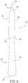
- FIG. 3depicts a side view of the first type of a surgical retractor shown in FIG. 2 .
- FIG. 4depicts a top view of a second type of a surgical retractor that may be used with the surgical retraction system of FIG. 1 .
- FIG. 5depicts a side view of the second type of a surgical retractor shown in FIG. 4 .
- FIG. 6depicts a perspective view of a handle adaptor coupled to a universal joint of the retraction system of FIG. 1 .
- FIG. 7depicts a first cross-section of the handle adaptor shown in FIG. 6 .
- FIG. 8depicts a second cross-section of the handle adaptor shown in FIG. 6 .
- FIG. 9provides an enlarged view of the swivel clamp portion of the handle adaptor shown in FIG. 8 .
- “and/or”means any one or more of the items in the list joined by “and/or”.
- “x and/or y”means any element of the three-element set ⁇ (x), (y), (x, y) ⁇ . In other words, “x and/or y” means “one or both of x and y.”
- “x, y, and/or z”means any element of the seven-element set ⁇ (x), (y), (z), (x, y), (x, z), (y, z), (x, y, z) ⁇ . In other words, “x, y and/or z” means “one or more of x, y, and z.”
- first, second, etc.may be used herein to describe various elements, these elements should not be limited by these terms. These terms are only used to distinguish one element from another element. Thus, for example, a first element, a first component or a first section discussed below could be termed a second element, a second component or a second section without departing from the teachings of the present disclosure. Similarly, various spatial terms, such as “upper,” “lower,” “side,” and the like, may be used in distinguishing one element from another element in a relative manner. It should be understood, however, that components may be oriented in different manners, for example a component may be turned sideways so that its “top” surface is facing horizontally and its “side” surface is facing vertically, without departing from the teachings of the present disclosure.
- a surgical retraction system 10is shown in FIG. 1 .
- the surgical retraction system 10may be used to retract body tissue of a patient 20 along an incision 22 to assist the surgeon in accessing internal organs, bone structures, or other internal structures of the patient 20 .
- the retraction system 10may include one or more surgical retractors 30 that each have a handle 40 and a blade 50 .
- a distal end 52 of the retractor blade 50may be placed through the incision 22 .
- the distal end 52may be further placed under a bone structure of the patient 20 .
- the handle 40 extending from a proximal end 54 of the blade 50may be levered in a downward direction to cause the retractor 30 to pivot about the distal end 52 , which is engaged with the bone structure of the patient 20 .
- Such pivotingmay cause lateral movement of the retractor blade 50 away from the incision 22 and retract body tissue away from the incision 22 in the process.
- the retraction system 10may include one or more rail clamps 60 .
- Each rail clamp 60may be secured to a horizontal rail 62 located on each side of a conventional operating table.
- a post 70may extend vertically from a secured rail clamp 60 to provide support for a cross bar 80 .
- the cross bar 80may be secured to one of the posts 70 by a universal joint clamp 82 .
- one or more lateral arms 90may be secured to post 70 via another universal clamp 82 .
- the cross bar 80 and the one or more lateral arms 90generally define a frame 92 to which retractors 30 may be secured.
- FIG. 1depicts a single retractor 30 secured to lateral arm 90 of the retraction frame 92 via a universal clamp 82 and handle adaptor 100 .
- any number of retractors 30may be secured along the cross bar 80 via a corresponding number of universal clamps 82 and handle adaptors 100 .
- any number of retractors 30may be secured to one of the lateral arms 90 via a corresponding number of universal clamps 82 and handle adaptors 100 .
- the retractor 30may include the blade 50 and the handle 40 attached to a proximal end 54 of the blade.
- the retractor 30may have a single-piece construction in which the handle 40 and blade 50 are integrally formed from surgical-grade stainless steel.
- the retractor 30in other embodiments may utilize other surgically-safe materials and/or may have a multi-piece construction.
- the handle 40may be implemented as a separate piece that is welded or otherwise affixed to the blade 50 .
- the handle 40may be detachably secured to the blade 50 .
- the blade 50may comprise a blade body 56 having a proximal end 54 to which the handle 40 is attached and a distal end 52 to be inserted into the patient 20 .
- the blade body 56 and distal end 52are configured to contact a patient.
- the distal end 52may engage a bone structure or another internal, anatomical feature of the patient 20 .
- the blade body 56may provide a bottom surface 58 configured to engage and retract anatomy tissue proximate incision 22 .
- the proximal end 54 of the blade 50is integrally attached to the handle 40 .
- the handle 40may be a separate component that has been permanently attached to the proximal end 54 of the blade 50 .
- the proximal end 54may include a connector (not shown) such as, for example, a connection nipple. The connection nipple may permit detachably securing the handle 40 to the proximal end 54 of the blade 50 .
- the blade body 56may include a lower blade portion 60 and an upper blade portion 70 .
- the lower blade portion 60may be hook-shaped, which aids in engaging and/or securing the distal end 52 of the blade 50 to a bone structure or other internal structure of the patient 20 .
- the lower blade portion 60may be curved upwardly and the distal end 52 may be pointed such that the distal end 52 and an upper surface 62 of the lower blade portion 60 may engage and hook under a bone structure or other internal structure of the patient 20 .
- the upper blade portion 70may be curved downwardly.
- the upper blade portion 70is curved in the opposite direction as the lower blade portion 60 .
- Such opposite curvature of the lower and upper blade portions 60 , 70results in the blade body 56 have a generally S-shaped side profile as best shown in FIG. 3 .
- Such curvaturegenerally provides the retraction capabilities of the retractor 30 .
- the distal end 52may engage and hook under a bone structure or other internal structure of the patient 20 , thus creating a generally stationary pivot point about which the retractor 30 may rotate.
- pushing downward upon handle 40causes the retractor 30 to rotate about the pivot point causing the bottom surface 58 of the upper blade portion 70 to engage and retract soft tissue away from distal end 52 and the incision 22 .
- the handle 40may include a proximal end 42 and a distal end 44 .
- the distal end 44may be attached to the proximal end 54 of the blade 50 as discussed above.
- the proximal end 52may be configured in a manner that permits attaching or otherwise securing the retractor 30 to the frame of the retraction system 10 .
- the proximal end 42may include one or more holes 44 that pass between a top surface 45 and a bottom surface 46 of the handle 40 .
- a screw or other type of fastenermay pass through such holes 44 to secure the handle 40 of the retractor 30 directly to the frame of the retraction system 10 or to secure the handle 40 to the frame of the retraction system 10 via an adapter or other connector.
- FIGS. 4 and 5details of another embodiment of a surgical retractor 30 ′ are shown.
- the retractor 30 ′ of FIGS. 4 and 5may be implemented in a manner similar to the retractor 30 of FIGS. 2 and 3 .
- the retractor 30 ′does not include holes 44 in its handle 40 ′.
- the retractor handle 40 ′may provide a smooth, top surface 45 ′ and a smooth, bottom surface 46 ′.
- the retractor 30 ′may be secured to the frame of the retraction system 10 using fasteners that do not pass through the retractor 30 ′.
- the retractor 30 ′may be secured to the frame using rubber bands, ties, threads, which may be wrapped around the handle 40 ′.
- the surgical retraction system 10may utilize retractors 30 , 30 ′ that are secured to the frame via different manners.
- retractor 30may be secured via the use of screws passing through holes 44 whereas retractor 30 ′ may be secured via bands wrapped around handle 40 ′.
- directly securing retractors 30 , 30 ′ to the frame via screws, bands, or other fastenersis fairly restrictive and makes it difficult to properly place the retractor 30 , 30 ′ in the incision 22 while at the same time sufficiently securing the retractor 30 , 30 ′ to the frame such that the retractor 30 , 30 ′ does not shift during a surgical procedure.
- the handle adaptor 100 of FIG. 1is depicted in greater detail.
- the handle adaptor 100may be used to secure different types of retractors such as, for example, retractors 30 , 30 ′ to the surgical retention system frame. Moreover, due to its adjustment capabilities, the handle adaptor 100 may ease the process of securing such retractors 30 , 30 ′ to the frame.
- the handle adaptor 100may include an extension arm 110 , a hinge 120 , a swivel clamp 130 , and a stop 140 .
- the extension arm 110may comprise an elongated member having a distal end 112 and a proximal end 114 .
- the elongated member forming the extension arm 110may be rod-shaped with a circular cross section though other shapes and cross sections are contemplated.
- the extension arm 110may pass through a clamp 83 of a universal joint 82 that is used to secure the handle adaptor 100 to the surgical retraction system frame.
- the clamp 83may be loosened or disengaged to permit the extension arm 100 to slide and/or rotate with respect to the clamp 83 .
- the extension arm 110may be pulled away from the clamp 83 in direction D 1 to extend a distal end 112 of the arm 110 further from the frame.
- the extension arm 110may be pushed toward the clamp 83 in direction D 2 to retract the distal end 112 of the arm 110 closer to the frame.
- the extension arm 110may have a circular, cross-section.
- the clamp 83may likewise have a circular, cross-section.
- the cross-sections of the extension arm 110 and clamp 83may permit the extension arm 110 to be rotated freely about axis A 1 . Such rotation may be used to adjust an orientation of a pivot axis A 2 provided by the hinge 120 .
- the extension arm 100 and/or clamp 83 in other embodimentsmay have non-circular, cross-sections, which permit limited rotation of extension arm 100 about axis A 1 .
- an octagonal cross-sectionmay provide eight distinct orientations of the extension arm 110 with respect to the clamp 8 about axis A 1 .
- the stop 140may be affixed to a proximal end 114 of the extension arm 110 .
- the stop 140is generally configured to prevent the extension arm 110 from being inadvertently pulled too far from a disengaged, clamp 83 as the extension arm 110 is extended from the clamp 83 .
- the stop 140may have a greater outer circumference than an outer circumference of the extension arm 110 and an inner circumference of the disengaged, clamp 83 .
- the hinge 120may be affixed to the distal end 112 of the extension arm 110 .
- the hinge 120may comprise a first leaf 122 providing a barrel 124 and a second leaf 126 providing a pin 128 .
- the first leaf 122may be affixed to the distal end 112 of the extension arm 110 such that the barrel 124 projects from the distal end 112 .
- the first leaf 122has an outer circumference that is greater than the outer circumference of the extension arm 110 and the inner circumference of the disengaged, clamp 83 . In this manner, the first leaf 122 may function as another stop that prevents the extension arm 110 from being inadvertently pushed too far into the disengaged, clamp 83 as the extension arm 110 is retracted toward the clamp 83 .
- the pin 128 of the second leaf 126may pass through the barrel 124 of the first leaf 122 .
- the pin 128 and barrel 124may cooperate to provide a pivot point that permits the second leaf 126 to rotate about an axis A 2 that extends longitudinally along the pin 128 and barrel 124 .
- the first and second leaves 122 , 126may form the hinge 120 that permits movement of the clamp 130 in relation to the extension arm 110 about the axis A 2 .
- the first leaf 122provides the barrel 124 of the hinge 120 and the second leaf 126 provides the pin 128 of the hinge 120 .
- the first leaf 122may provide the pin 128 and the second leaf 126 may provide the barrel 124 .
- the handle adapter 100further includes the clamp 130 .
- the clamp 130is generally configured to receive and secure the handle 40 , 40 ′ of a retractor 30 , 30 ′ to the frame via hinge 120 and extension arm 110 .
- the clamp 130may include a clamp body 131 having a slot 132 configured to receive a handle 40 , 40 ′ of a retractor 30 , 30 ′ and a screw 135 configured to engage a surface of the handle 40 , 40 ′.
- the slot 132 of the clamp body 131may be defined by an proximal surface 133 and a distal surface 134 that respectively align with an upper surface and lower surface of the handle 40 , 40 ′ when such a handle is inserted into the slot 132 .
- the screw 135may extend through a distal end 138 of the clamp body 131 such that the screw 135 passes through the proximal surface 133 of the slot 132 . Tightening the screw 135 may cause a tip 136 of the screw 135 to advance into the slot 132 , engage an upper surface of the handle 40 , 40 ′, and clamp the handle 40 , 40 ′ between the tip 136 and the distal surface 134 of the slot 132 .
- the screw 135may include an enlarged head or knob 137 opposite its tip 136 , which may permit hand tightening and loosening of the screw 135 .
- the handle 40 , 40 ′may be secured in the clamp 130 without the need of an external tool such as a screwdriver or wrench.
- the proximal end 139 of the clamp body 131is secured to the second leaf 126 of the hinge 120 . In this manner, the clamp body 131 may pivot with respect to the extension arm 110 about the axis A 2 .
- the proximal end 139 of the clamp body 131is secured to the second leaf 126 via a swivel connection 140 as best shown in FIGS. 7-9 .
- the swivel connection 140includes a pin 142 having a head 144 and distal end 146 .
- the pin 142passes through a bearing 150 in a base 152 of the second leaf 126 of the hinge 120 .
- the distal end 146is affixed to the proximal end 139 of the clamp body 131 .
- the head 144is sized to be greater than opening provided by the bearing 150 .
- the clamp body 131is secured to the hinge 120 , but permitted to swivel about the axis A 3 provide by pin 142 .
- the swivel axis A 3is distinct or at a different orientation than the hinge axis A 2 provided by hinge 120 .
- the swivel axis A 3is perpendicular to the hinge axis A 2 .
Landscapes
- Health & Medical Sciences (AREA)
- Life Sciences & Earth Sciences (AREA)
- Surgery (AREA)
- Molecular Biology (AREA)
- Engineering & Computer Science (AREA)
- Biomedical Technology (AREA)
- Heart & Thoracic Surgery (AREA)
- Medical Informatics (AREA)
- Nuclear Medicine, Radiotherapy & Molecular Imaging (AREA)
- Animal Behavior & Ethology (AREA)
- General Health & Medical Sciences (AREA)
- Public Health (AREA)
- Veterinary Medicine (AREA)
- Oral & Maxillofacial Surgery (AREA)
- Pathology (AREA)
- Surgical Instruments (AREA)
Abstract
Description
Claims (20)
Priority Applications (1)
| Application Number | Priority Date | Filing Date | Title |
|---|---|---|---|
| US15/334,797US10786328B2 (en) | 2016-10-26 | 2016-10-26 | Adaptor handle for surgical retractor |
Applications Claiming Priority (1)
| Application Number | Priority Date | Filing Date | Title |
|---|---|---|---|
| US15/334,797US10786328B2 (en) | 2016-10-26 | 2016-10-26 | Adaptor handle for surgical retractor |
Publications (2)
| Publication Number | Publication Date |
|---|---|
| US20180110505A1 US20180110505A1 (en) | 2018-04-26 |
| US10786328B2true US10786328B2 (en) | 2020-09-29 |
Family
ID=61971591
Family Applications (1)
| Application Number | Title | Priority Date | Filing Date |
|---|---|---|---|
| US15/334,797Active2037-06-24US10786328B2 (en) | 2016-10-26 | 2016-10-26 | Adaptor handle for surgical retractor |
Country Status (1)
| Country | Link |
|---|---|
| US (1) | US10786328B2 (en) |
Families Citing this family (2)
| Publication number | Priority date | Publication date | Assignee | Title |
|---|---|---|---|---|
| AU2021229480B2 (en)* | 2020-03-03 | 2023-11-23 | Encore Medical, Lp Dba Djo Surgical | Surgical tissue retractor holding frame |
| US12318080B2 (en)* | 2023-07-21 | 2025-06-03 | Coopersurgical, Inc. | Illuminated surgical retractor capable of hand-held operation and of being mounted to a fixed frame |
Citations (106)
| Publication number | Priority date | Publication date | Assignee | Title |
|---|---|---|---|---|
| US2670732A (en)* | 1952-08-11 | 1954-03-02 | Ole A Nelson | Surgical retractor |
| US3384077A (en)* | 1965-01-22 | 1968-05-21 | William K. Gauthier | Abdominal retractor device |
| US3509873A (en)* | 1967-04-24 | 1970-05-05 | Jack B Karlin | Retractor |
| US3858578A (en)* | 1974-01-21 | 1975-01-07 | Pravel Wilson & Matthews | Surgical retaining device |
| US3910538A (en)* | 1973-05-04 | 1975-10-07 | Carlo Baitella | Jointed stand for dial gages |
| US4116232A (en)* | 1977-03-07 | 1978-09-26 | Philipp Rabban | Surgical retractor |
| US4143652A (en)* | 1976-01-29 | 1979-03-13 | Hans Meier | Surgical retaining device |
| US4402481A (en)* | 1981-02-27 | 1983-09-06 | Mitutoyo Mfg. Co., Ltd. | Articulated device for service component |
| US4461284A (en)* | 1982-09-30 | 1984-07-24 | Fackler Martin L | Surgical retaining device |
| US4467791A (en)* | 1981-07-27 | 1984-08-28 | Codman & Shurtleff, Inc. | Surgical retractor holder |
| US4606522A (en)* | 1984-08-23 | 1986-08-19 | Heifetz Milton D | Position adjustable instrument holder |
| US4616635A (en)* | 1984-04-04 | 1986-10-14 | Aesculap-Werke Aktiengesellschaft | Surgical instrument for the splaying of wound edges |
| US4653481A (en)* | 1985-07-24 | 1987-03-31 | Howland Robert S | Advanced spine fixation system and method |
| US4934352A (en)* | 1982-10-22 | 1990-06-19 | Sullivan Jr Eugene M | Surgical retractor handle construction |
| US4971037A (en)* | 1988-09-19 | 1990-11-20 | Pilling Co. | Surgical retractor support |
| US5035232A (en)* | 1987-10-24 | 1991-07-30 | Aesculap Ag | Retractor |
| US5303694A (en) | 1993-02-09 | 1994-04-19 | Mikhail Michael W E | Method for performing hip surgery and retractor for use therein |
| US5320444A (en)* | 1993-01-22 | 1994-06-14 | Bookwalter John R | Enclosed surgical apparatus clamp |
| US5365921A (en)* | 1993-01-22 | 1994-11-22 | Bookwalter John R | Flip-up sternal retractor |
| US5375481A (en)* | 1993-11-12 | 1994-12-27 | Codman & Shurtleff, Inc. | Multi-position ratchet mechanism |
| US5380331A (en)* | 1990-04-11 | 1995-01-10 | Mikhail; W. E. Michael | Method for performing knee surgery and retractors for use therein |
| US5513827A (en)* | 1993-07-26 | 1996-05-07 | Karlin Technology, Inc. | Gooseneck surgical instrument holder |
| USD369860S (en)* | 1994-11-10 | 1996-05-14 | Tibor Koros | Combined cervical and microdiscectomy retractor blade with detachable handle |
| US5520610A (en)* | 1991-05-31 | 1996-05-28 | Giglio; Steven R. | Self retaining retractor |
| US5609565A (en)* | 1994-08-09 | 1997-03-11 | Mitaka Kohki Co., Ltd. | Articulated tool-holding arm |
| US5738685A (en)* | 1993-05-18 | 1998-04-14 | Schafer Micomed Gmbh | Osteosynthesis device |
| US5746743A (en)* | 1990-07-13 | 1998-05-05 | Greenberg Surgical Technologies, Llc | Single-handed surgical drill depth guide with mandibular retractor |
| US5772583A (en)* | 1994-01-21 | 1998-06-30 | Wright; John T. M. | Sternal retractor with attachments for mitral & tricuspid valve repair |
| US5846191A (en)* | 1996-09-13 | 1998-12-08 | Genzyme Corporation | Redo sternotomy retractor |
| US5902233A (en)* | 1996-12-13 | 1999-05-11 | Thompson Surgical Instruments, Inc. | Angling surgical retractor apparatus and method of retracting anatomy |
| US5918844A (en)* | 1993-10-21 | 1999-07-06 | Ognier; Jean-Francois | Support device for medical or surgical instrument |
| US5967973A (en)* | 1996-04-26 | 1999-10-19 | United States Surgical | Surgical retractor and method of surgery |
| US5984865A (en)* | 1998-09-15 | 1999-11-16 | Thompson Surgical Instruments, Inc. | Surgical retractor having locking interchangeable blades |
| US5984867A (en)* | 1997-05-02 | 1999-11-16 | Heartport, Inc. | Surgical retractor and method of retracting |
| US6083154A (en)* | 1997-10-23 | 2000-07-04 | Sofamor S.N.C. | Surgical instrumentation and method for retracting and shifting tissues |
| US6085749A (en)* | 1996-02-26 | 2000-07-11 | Ethicon Endo-Surgery, Inc. | Articulating guide arm for medical applications |
| US6132370A (en)* | 1996-04-26 | 2000-10-17 | Genzyme Corporation | Retractor-mounted coronary stabilizer |
| US6254535B1 (en)* | 1996-04-26 | 2001-07-03 | Genzyme Corporation | Ball and socket coronary stabilizer |
| US20010020121A1 (en)* | 1999-05-04 | 2001-09-06 | Lawrence W. Hu | Surgical retractor platform blade apparatus |
| US20010025136A1 (en)* | 1996-02-20 | 2001-09-27 | Leonard Harry L. | Surgical instruments and procedures for stabilizing a localized portion of a beating heart |
| US20010034473A1 (en)* | 1997-09-30 | 2001-10-25 | Raymond Cartier | Sternum retractor for performing bypass surgery on a beating heart |
| US6315718B1 (en)* | 1999-10-04 | 2001-11-13 | Minnesota Scientific, Inc. | Method for hip retraction |
| US6322500B1 (en)* | 1996-12-23 | 2001-11-27 | University Of Massachusetts | Minimally invasive surgical apparatus |
| US6338738B1 (en)* | 1999-08-31 | 2002-01-15 | Edwards Lifesciences Corp. | Device and method for stabilizing cardiac tissue |
| US6340345B1 (en)* | 1999-03-18 | 2002-01-22 | Automated Medical Products Corp. | Surgical retractor blade and handle for movement with two degrees of freedom |
| US6368271B1 (en)* | 2000-09-01 | 2002-04-09 | Minnesota Scientific, Inc. | Method for humerus retraction |
| US20020058856A1 (en)* | 1999-09-07 | 2002-05-16 | Origin Medsystems, Inc. | Locking arm having ball joints for use in an organ manipulator apparatus |
| US20020161446A1 (en)* | 2000-08-08 | 2002-10-31 | Vincent Bryan | Method and apparatus for stereotactic impleantation |
| US6572540B2 (en)* | 2001-05-24 | 2003-06-03 | Minnesota Scientific, Inc. | Cam-wedge locking mechanism |
| US20030139651A1 (en)* | 2002-01-23 | 2003-07-24 | Holland Donna D. | Illuminated retractor for use in connection with harvesting a blood vessel from the arm |
| US20030191372A1 (en)* | 2001-05-24 | 2003-10-09 | Minnesota Scientific, Inc. | Cam-wedge locking mechanism |
| US20030220547A1 (en)* | 2002-05-23 | 2003-11-27 | Holland Donna D. | Pivotal and illuminated saphenous vein retractor with tapered design |
| US6673073B1 (en)* | 1999-11-29 | 2004-01-06 | Schaefer Bernd | Transverse connector |
| US20040127773A1 (en)* | 2002-12-31 | 2004-07-01 | Ethicon, Inc. | Curved rack retractor |
| US20040129109A1 (en)* | 2002-10-15 | 2004-07-08 | Phillips Burns P. | Swivel retractor blade assembly |
| US20040147812A1 (en)* | 2002-10-02 | 2004-07-29 | Hamel Ross J. | Retractor with interchangeable retractor blades |
| US20040193018A1 (en)* | 2003-03-31 | 2004-09-30 | Depuy Acromed | Surgical retractor |
| US20040199055A1 (en)* | 2003-04-02 | 2004-10-07 | Mulac Anthony J. | Crank retractor handle |
| US6808493B1 (en)* | 2002-08-28 | 2004-10-26 | Flexbar Machine Corp | Adjustable ratchet retractor support apparatus |
| US20040230191A1 (en)* | 2002-11-23 | 2004-11-18 | George Frey | Distraction and retraction system for spinal surgery |
| US20040242968A1 (en)* | 2002-11-19 | 2004-12-02 | Hill J. Donald | Methods, systems, and apparatus for performing minimally invasive coronary artery bypass graft surgery |
| US20050020885A1 (en)* | 2003-04-29 | 2005-01-27 | Joachim Rein | Device for retracting tissue |
| US20050043717A1 (en)* | 1999-10-01 | 2005-02-24 | Computer Motion, Inc. | Heart stabilizer |
| US6860877B1 (en)* | 2000-09-29 | 2005-03-01 | Computer Motion, Inc. | Heart stabilizer support arm |
| US20050119697A1 (en) | 2001-11-21 | 2005-06-02 | Minnesota Scientific, Inc. | Method of table mounted retraction in hip surgery |
| US20060063977A1 (en)* | 1998-10-02 | 2006-03-23 | The LeVahn Intellectual Property Holding Company, LLC | Adjustable retractor support |
| US7118571B2 (en)* | 2000-07-28 | 2006-10-10 | Synthes (U.S.A.) | Spinal fixation system |
| US20070066872A1 (en) | 2003-03-07 | 2007-03-22 | Paul Morrison | IIIuminable retractor |
| US20070093696A1 (en)* | 2001-11-21 | 2007-04-26 | The LeVahn Intellectual Property Holding Company, LLC | Method of table mounted retraction in hip surgery and surgical retractor |
| US20070213597A1 (en)* | 2006-03-01 | 2007-09-13 | Wooster Nicholas H | Surgical retractor frame system |
| US20070282311A1 (en)* | 2006-06-01 | 2007-12-06 | Scott Christopher P | Multi-joint fixture system |
| US20080071145A1 (en)* | 2006-09-19 | 2008-03-20 | Levahn Intellectual Property Holding Company, Llc | Support Clamp For Retractor Bar Stock Of Generally Rectangular Cross-Section |
| US20080076968A1 (en)* | 2006-05-19 | 2008-03-27 | Zemco Manufacturing Inc. | Surgical tool |
| US20080161650A1 (en)* | 2006-07-19 | 2008-07-03 | Zimmer Spine, Inc. | Surgical access system and method of using the same |
| US20080221586A1 (en)* | 2007-02-09 | 2008-09-11 | Alphatec Spine, Inc. | Curviliner spinal access method and device |
| US20090012370A1 (en) | 2007-06-28 | 2009-01-08 | Hialy Riviera Gutierrez | Posterior tissue retractor for use in hip replacement surgery |
| US7537565B2 (en)* | 2005-09-27 | 2009-05-26 | Daniel Bass | Surgical retractor with rotating blades |
| US20090204148A1 (en)* | 2008-02-07 | 2009-08-13 | Warsaw Orthopedic, Inc. | Adjustable Vertebral Body Elevator |
| US20090264710A1 (en)* | 2006-04-29 | 2009-10-22 | Comis Orthopaedics Limited | Surgical apparatus |
| US20100081886A1 (en)* | 2008-09-30 | 2010-04-01 | Olympus Corporation | Surgical manipulator system |
| US20100113885A1 (en)* | 2008-10-30 | 2010-05-06 | Warsaw Orthopedic, Inc. | Retractor assemblies for surgery in a patient |
| US7753844B2 (en)* | 2003-10-17 | 2010-07-13 | Minnesota Scientific, Inc. | Articulated retractor blade holder |
| US20100217089A1 (en)* | 2009-02-24 | 2010-08-26 | Thompson Surgical Instruments, Inc. | Surgical Retractor with Locking Blade |
| US20100256454A1 (en)* | 2009-02-24 | 2010-10-07 | Thompson Surgical Instruments, Inc. | Surgical Retractor Angling Device |
| US20110137130A1 (en)* | 2009-12-03 | 2011-06-09 | John Thalgott | Posterior Lumbar Retractor System |
| US20110270042A1 (en)* | 2010-04-29 | 2011-11-03 | Pier Cristoforo Giulianotti | Adjustable surgical support and retractor system |
| US8216133B2 (en)* | 2006-05-23 | 2012-07-10 | Chappuis James L | Doppler retractor |
| US20120238828A1 (en)* | 2006-08-17 | 2012-09-20 | Helmut Fricke | Surgical retractor mechanism |
| USRE43806E1 (en)* | 1993-12-14 | 2012-11-20 | National Products, Inc. | Universally positionable mounting device |
| US20120298820A1 (en)* | 2011-05-25 | 2012-11-29 | Spiros Manolidis | Surgical tool holder |
| US20130066162A1 (en)* | 2010-04-19 | 2013-03-14 | Condor Gmbh Medicaltechnik | Tensioning device of a surgical retractor |
| US20130245383A1 (en)* | 2012-03-13 | 2013-09-19 | Adam Friedrich | System and Method for Retracting Body Tissue |
| US8623022B2 (en)* | 2010-09-20 | 2014-01-07 | Zimmer Spine, Inc. | Surgical instrument support system and method |
| US20140039267A1 (en)* | 2012-05-28 | 2014-02-06 | Retrospine Pty Ltd | Clamping Retractor Assembly |
| US8900137B1 (en)* | 2011-04-26 | 2014-12-02 | Nuvasive, Inc. | Cervical retractor |
| US20150087918A1 (en)* | 2012-05-25 | 2015-03-26 | The Board Of Regents Of The University Of Oklahoma | Surgical retractor system and method |
| US20150157306A1 (en)* | 2013-12-11 | 2015-06-11 | Pro Med Instruments Gmbh | Surgical Retractor System and Method |
| US20150282795A1 (en)* | 2012-10-29 | 2015-10-08 | Aesculap Ag | Atrium retractor |
| US9179945B2 (en)* | 2013-08-20 | 2015-11-10 | Shao-Kang Hsueh | Minimally invasive spinal fixator implant surgical device |
| US9237933B2 (en)* | 2011-10-21 | 2016-01-19 | Specialty Surgical Instrumentation Inc. | Universal arm system |
| US20160242757A1 (en)* | 2015-02-25 | 2016-08-25 | Globus Medical, Inc. | Surgical retractor systems and methods |
| US20160287234A1 (en)* | 2015-04-03 | 2016-10-06 | Tedan Surgical Innovations, LLC. | Retractor blade assembly |
| US20170042527A1 (en)* | 2015-08-10 | 2017-02-16 | Thompson Surgical Instruments, Inc. | Surgical retractor having clamping mechanism |
| US9636097B2 (en)* | 2014-07-31 | 2017-05-02 | Tedan Surgical Innovations, LLC. | Surgical retractor with a locking retractor blade |
| US9872675B2 (en)* | 2013-12-02 | 2018-01-23 | Thompson Surgical Instruments, Inc. | Surgical retractor with angling device |
| US9918795B2 (en)* | 2012-12-20 | 2018-03-20 | MAQUET GmbH | Instrument holder |
- 2016
- 2016-10-26USUS15/334,797patent/US10786328B2/enactiveActive
Patent Citations (108)
| Publication number | Priority date | Publication date | Assignee | Title |
|---|---|---|---|---|
| US2670732A (en)* | 1952-08-11 | 1954-03-02 | Ole A Nelson | Surgical retractor |
| US3384077A (en)* | 1965-01-22 | 1968-05-21 | William K. Gauthier | Abdominal retractor device |
| US3509873A (en)* | 1967-04-24 | 1970-05-05 | Jack B Karlin | Retractor |
| US3910538A (en)* | 1973-05-04 | 1975-10-07 | Carlo Baitella | Jointed stand for dial gages |
| US3858578A (en)* | 1974-01-21 | 1975-01-07 | Pravel Wilson & Matthews | Surgical retaining device |
| US4143652A (en)* | 1976-01-29 | 1979-03-13 | Hans Meier | Surgical retaining device |
| US4116232A (en)* | 1977-03-07 | 1978-09-26 | Philipp Rabban | Surgical retractor |
| US4402481A (en)* | 1981-02-27 | 1983-09-06 | Mitutoyo Mfg. Co., Ltd. | Articulated device for service component |
| US4467791A (en)* | 1981-07-27 | 1984-08-28 | Codman & Shurtleff, Inc. | Surgical retractor holder |
| US4461284A (en)* | 1982-09-30 | 1984-07-24 | Fackler Martin L | Surgical retaining device |
| US4934352A (en)* | 1982-10-22 | 1990-06-19 | Sullivan Jr Eugene M | Surgical retractor handle construction |
| US4616635A (en)* | 1984-04-04 | 1986-10-14 | Aesculap-Werke Aktiengesellschaft | Surgical instrument for the splaying of wound edges |
| US4606522A (en)* | 1984-08-23 | 1986-08-19 | Heifetz Milton D | Position adjustable instrument holder |
| US4653481A (en)* | 1985-07-24 | 1987-03-31 | Howland Robert S | Advanced spine fixation system and method |
| US5035232A (en)* | 1987-10-24 | 1991-07-30 | Aesculap Ag | Retractor |
| US4971037A (en)* | 1988-09-19 | 1990-11-20 | Pilling Co. | Surgical retractor support |
| US5380331A (en)* | 1990-04-11 | 1995-01-10 | Mikhail; W. E. Michael | Method for performing knee surgery and retractors for use therein |
| US5746743A (en)* | 1990-07-13 | 1998-05-05 | Greenberg Surgical Technologies, Llc | Single-handed surgical drill depth guide with mandibular retractor |
| US5520610A (en)* | 1991-05-31 | 1996-05-28 | Giglio; Steven R. | Self retaining retractor |
| US5320444A (en)* | 1993-01-22 | 1994-06-14 | Bookwalter John R | Enclosed surgical apparatus clamp |
| US5365921A (en)* | 1993-01-22 | 1994-11-22 | Bookwalter John R | Flip-up sternal retractor |
| US5303694A (en) | 1993-02-09 | 1994-04-19 | Mikhail Michael W E | Method for performing hip surgery and retractor for use therein |
| US5738685A (en)* | 1993-05-18 | 1998-04-14 | Schafer Micomed Gmbh | Osteosynthesis device |
| US5513827A (en)* | 1993-07-26 | 1996-05-07 | Karlin Technology, Inc. | Gooseneck surgical instrument holder |
| US5918844A (en)* | 1993-10-21 | 1999-07-06 | Ognier; Jean-Francois | Support device for medical or surgical instrument |
| US5375481A (en)* | 1993-11-12 | 1994-12-27 | Codman & Shurtleff, Inc. | Multi-position ratchet mechanism |
| USRE43806E1 (en)* | 1993-12-14 | 2012-11-20 | National Products, Inc. | Universally positionable mounting device |
| US5772583A (en)* | 1994-01-21 | 1998-06-30 | Wright; John T. M. | Sternal retractor with attachments for mitral & tricuspid valve repair |
| US5609565A (en)* | 1994-08-09 | 1997-03-11 | Mitaka Kohki Co., Ltd. | Articulated tool-holding arm |
| USD369860S (en)* | 1994-11-10 | 1996-05-14 | Tibor Koros | Combined cervical and microdiscectomy retractor blade with detachable handle |
| US20010025136A1 (en)* | 1996-02-20 | 2001-09-27 | Leonard Harry L. | Surgical instruments and procedures for stabilizing a localized portion of a beating heart |
| US6085749A (en)* | 1996-02-26 | 2000-07-11 | Ethicon Endo-Surgery, Inc. | Articulating guide arm for medical applications |
| US5967973A (en)* | 1996-04-26 | 1999-10-19 | United States Surgical | Surgical retractor and method of surgery |
| US6132370A (en)* | 1996-04-26 | 2000-10-17 | Genzyme Corporation | Retractor-mounted coronary stabilizer |
| US6254535B1 (en)* | 1996-04-26 | 2001-07-03 | Genzyme Corporation | Ball and socket coronary stabilizer |
| US5846191A (en)* | 1996-09-13 | 1998-12-08 | Genzyme Corporation | Redo sternotomy retractor |
| US5902233A (en)* | 1996-12-13 | 1999-05-11 | Thompson Surgical Instruments, Inc. | Angling surgical retractor apparatus and method of retracting anatomy |
| US6322500B1 (en)* | 1996-12-23 | 2001-11-27 | University Of Massachusetts | Minimally invasive surgical apparatus |
| US5984867A (en)* | 1997-05-02 | 1999-11-16 | Heartport, Inc. | Surgical retractor and method of retracting |
| US20010034473A1 (en)* | 1997-09-30 | 2001-10-25 | Raymond Cartier | Sternum retractor for performing bypass surgery on a beating heart |
| US6083154A (en)* | 1997-10-23 | 2000-07-04 | Sofamor S.N.C. | Surgical instrumentation and method for retracting and shifting tissues |
| US5984865A (en)* | 1998-09-15 | 1999-11-16 | Thompson Surgical Instruments, Inc. | Surgical retractor having locking interchangeable blades |
| US20060063977A1 (en)* | 1998-10-02 | 2006-03-23 | The LeVahn Intellectual Property Holding Company, LLC | Adjustable retractor support |
| US6340345B1 (en)* | 1999-03-18 | 2002-01-22 | Automated Medical Products Corp. | Surgical retractor blade and handle for movement with two degrees of freedom |
| US20010020121A1 (en)* | 1999-05-04 | 2001-09-06 | Lawrence W. Hu | Surgical retractor platform blade apparatus |
| US6338738B1 (en)* | 1999-08-31 | 2002-01-15 | Edwards Lifesciences Corp. | Device and method for stabilizing cardiac tissue |
| US20020058856A1 (en)* | 1999-09-07 | 2002-05-16 | Origin Medsystems, Inc. | Locking arm having ball joints for use in an organ manipulator apparatus |
| US20050043717A1 (en)* | 1999-10-01 | 2005-02-24 | Computer Motion, Inc. | Heart stabilizer |
| US6315718B1 (en)* | 1999-10-04 | 2001-11-13 | Minnesota Scientific, Inc. | Method for hip retraction |
| US6673073B1 (en)* | 1999-11-29 | 2004-01-06 | Schaefer Bernd | Transverse connector |
| US7118571B2 (en)* | 2000-07-28 | 2006-10-10 | Synthes (U.S.A.) | Spinal fixation system |
| US20020161446A1 (en)* | 2000-08-08 | 2002-10-31 | Vincent Bryan | Method and apparatus for stereotactic impleantation |
| US6368271B1 (en)* | 2000-09-01 | 2002-04-09 | Minnesota Scientific, Inc. | Method for humerus retraction |
| US6860877B1 (en)* | 2000-09-29 | 2005-03-01 | Computer Motion, Inc. | Heart stabilizer support arm |
| US20030191372A1 (en)* | 2001-05-24 | 2003-10-09 | Minnesota Scientific, Inc. | Cam-wedge locking mechanism |
| US6572540B2 (en)* | 2001-05-24 | 2003-06-03 | Minnesota Scientific, Inc. | Cam-wedge locking mechanism |
| US20070093696A1 (en)* | 2001-11-21 | 2007-04-26 | The LeVahn Intellectual Property Holding Company, LLC | Method of table mounted retraction in hip surgery and surgical retractor |
| US20050119697A1 (en) | 2001-11-21 | 2005-06-02 | Minnesota Scientific, Inc. | Method of table mounted retraction in hip surgery |
| US20030139651A1 (en)* | 2002-01-23 | 2003-07-24 | Holland Donna D. | Illuminated retractor for use in connection with harvesting a blood vessel from the arm |
| US20030220547A1 (en)* | 2002-05-23 | 2003-11-27 | Holland Donna D. | Pivotal and illuminated saphenous vein retractor with tapered design |
| US6808493B1 (en)* | 2002-08-28 | 2004-10-26 | Flexbar Machine Corp | Adjustable ratchet retractor support apparatus |
| US20040147812A1 (en)* | 2002-10-02 | 2004-07-29 | Hamel Ross J. | Retractor with interchangeable retractor blades |
| US20040129109A1 (en)* | 2002-10-15 | 2004-07-08 | Phillips Burns P. | Swivel retractor blade assembly |
| US20040242968A1 (en)* | 2002-11-19 | 2004-12-02 | Hill J. Donald | Methods, systems, and apparatus for performing minimally invasive coronary artery bypass graft surgery |
| US20040230191A1 (en)* | 2002-11-23 | 2004-11-18 | George Frey | Distraction and retraction system for spinal surgery |
| US20040127773A1 (en)* | 2002-12-31 | 2004-07-01 | Ethicon, Inc. | Curved rack retractor |
| US20070066872A1 (en) | 2003-03-07 | 2007-03-22 | Paul Morrison | IIIuminable retractor |
| US20040193018A1 (en)* | 2003-03-31 | 2004-09-30 | Depuy Acromed | Surgical retractor |
| US20040199055A1 (en)* | 2003-04-02 | 2004-10-07 | Mulac Anthony J. | Crank retractor handle |
| US20050020885A1 (en)* | 2003-04-29 | 2005-01-27 | Joachim Rein | Device for retracting tissue |
| US7753844B2 (en)* | 2003-10-17 | 2010-07-13 | Minnesota Scientific, Inc. | Articulated retractor blade holder |
| US7537565B2 (en)* | 2005-09-27 | 2009-05-26 | Daniel Bass | Surgical retractor with rotating blades |
| US20070213597A1 (en)* | 2006-03-01 | 2007-09-13 | Wooster Nicholas H | Surgical retractor frame system |
| US20090264710A1 (en)* | 2006-04-29 | 2009-10-22 | Comis Orthopaedics Limited | Surgical apparatus |
| US20080076968A1 (en)* | 2006-05-19 | 2008-03-27 | Zemco Manufacturing Inc. | Surgical tool |
| US8216133B2 (en)* | 2006-05-23 | 2012-07-10 | Chappuis James L | Doppler retractor |
| US20070282311A1 (en)* | 2006-06-01 | 2007-12-06 | Scott Christopher P | Multi-joint fixture system |
| US20080161650A1 (en)* | 2006-07-19 | 2008-07-03 | Zimmer Spine, Inc. | Surgical access system and method of using the same |
| US20120238828A1 (en)* | 2006-08-17 | 2012-09-20 | Helmut Fricke | Surgical retractor mechanism |
| US20080071145A1 (en)* | 2006-09-19 | 2008-03-20 | Levahn Intellectual Property Holding Company, Llc | Support Clamp For Retractor Bar Stock Of Generally Rectangular Cross-Section |
| US20080221586A1 (en)* | 2007-02-09 | 2008-09-11 | Alphatec Spine, Inc. | Curviliner spinal access method and device |
| US20090012370A1 (en) | 2007-06-28 | 2009-01-08 | Hialy Riviera Gutierrez | Posterior tissue retractor for use in hip replacement surgery |
| US20090204148A1 (en)* | 2008-02-07 | 2009-08-13 | Warsaw Orthopedic, Inc. | Adjustable Vertebral Body Elevator |
| US20100081886A1 (en)* | 2008-09-30 | 2010-04-01 | Olympus Corporation | Surgical manipulator system |
| US20100113885A1 (en)* | 2008-10-30 | 2010-05-06 | Warsaw Orthopedic, Inc. | Retractor assemblies for surgery in a patient |
| US20100217089A1 (en)* | 2009-02-24 | 2010-08-26 | Thompson Surgical Instruments, Inc. | Surgical Retractor with Locking Blade |
| US20100256454A1 (en)* | 2009-02-24 | 2010-10-07 | Thompson Surgical Instruments, Inc. | Surgical Retractor Angling Device |
| US20110137130A1 (en)* | 2009-12-03 | 2011-06-09 | John Thalgott | Posterior Lumbar Retractor System |
| US20130066162A1 (en)* | 2010-04-19 | 2013-03-14 | Condor Gmbh Medicaltechnik | Tensioning device of a surgical retractor |
| US20110270042A1 (en)* | 2010-04-29 | 2011-11-03 | Pier Cristoforo Giulianotti | Adjustable surgical support and retractor system |
| US8623022B2 (en)* | 2010-09-20 | 2014-01-07 | Zimmer Spine, Inc. | Surgical instrument support system and method |
| US8900137B1 (en)* | 2011-04-26 | 2014-12-02 | Nuvasive, Inc. | Cervical retractor |
| US20120298820A1 (en)* | 2011-05-25 | 2012-11-29 | Spiros Manolidis | Surgical tool holder |
| US9237933B2 (en)* | 2011-10-21 | 2016-01-19 | Specialty Surgical Instrumentation Inc. | Universal arm system |
| US20180021033A1 (en)* | 2012-03-13 | 2018-01-25 | Globus Medical, Inc. | System and method for retracting body tissue |
| US20130245383A1 (en)* | 2012-03-13 | 2013-09-19 | Adam Friedrich | System and Method for Retracting Body Tissue |
| US20150087918A1 (en)* | 2012-05-25 | 2015-03-26 | The Board Of Regents Of The University Of Oklahoma | Surgical retractor system and method |
| US20140039267A1 (en)* | 2012-05-28 | 2014-02-06 | Retrospine Pty Ltd | Clamping Retractor Assembly |
| US20150282795A1 (en)* | 2012-10-29 | 2015-10-08 | Aesculap Ag | Atrium retractor |
| US9918795B2 (en)* | 2012-12-20 | 2018-03-20 | MAQUET GmbH | Instrument holder |
| US9179945B2 (en)* | 2013-08-20 | 2015-11-10 | Shao-Kang Hsueh | Minimally invasive spinal fixator implant surgical device |
| US9872675B2 (en)* | 2013-12-02 | 2018-01-23 | Thompson Surgical Instruments, Inc. | Surgical retractor with angling device |
| US20150157306A1 (en)* | 2013-12-11 | 2015-06-11 | Pro Med Instruments Gmbh | Surgical Retractor System and Method |
| US9636097B2 (en)* | 2014-07-31 | 2017-05-02 | Tedan Surgical Innovations, LLC. | Surgical retractor with a locking retractor blade |
| US20160242757A1 (en)* | 2015-02-25 | 2016-08-25 | Globus Medical, Inc. | Surgical retractor systems and methods |
| US20160287234A1 (en)* | 2015-04-03 | 2016-10-06 | Tedan Surgical Innovations, LLC. | Retractor blade assembly |
| US9848862B2 (en)* | 2015-04-03 | 2017-12-26 | Tedan Surgical Innovations, LLC. | Retractor blade assembly |
| US20170042527A1 (en)* | 2015-08-10 | 2017-02-16 | Thompson Surgical Instruments, Inc. | Surgical retractor having clamping mechanism |
Also Published As
| Publication number | Publication date |
|---|---|
| US20180110505A1 (en) | 2018-04-26 |
Similar Documents
| Publication | Publication Date | Title |
|---|---|---|
| US8961565B2 (en) | Transverse rod connector | |
| US10856918B2 (en) | Moveable bone plate implantation system and method of use | |
| US20220395283A1 (en) | Mis cross-connector | |
| US9277906B2 (en) | Quick-release handle for retractor blades | |
| US20090105547A1 (en) | Adjustable Retractor Blade | |
| US20160354073A1 (en) | Pedicle mountable retractor system | |
| US20100198269A1 (en) | Spinal Implants with Multi-Axial Anchor Assembly and Methods | |
| US20110257657A1 (en) | Medical aligning device | |
| US20100318132A1 (en) | Spinal Implants and Methods With Extended Multi-Axial Anchor Assemblies | |
| US20120123428A1 (en) | Repositioning Forceps With A Drilling Aid | |
| US10743924B2 (en) | Bone reduction and implant holding instrument | |
| US20170065268A1 (en) | Surgical retractor with asymmetric blade | |
| US20100305407A1 (en) | Malleable Port Retractor | |
| US10786328B2 (en) | Adaptor handle for surgical retractor | |
| EP2311400A2 (en) | Surgical head clamp | |
| US11806002B2 (en) | Retractor system and retractor arm with detachable handle | |
| US7785254B2 (en) | Surgical tool holder | |
| US20160235421A1 (en) | Positioning Bracket for Multiple Bone Tunnel Drill Guides | |
| US12070200B2 (en) | Ring retractor system | |
| US7850696B2 (en) | Device for facilitating reduction and repair of fractures of the small bones | |
| US20240008862A1 (en) | Retractor system and retractor arm with detachable handle | |
| US20240197310A1 (en) | Surgical retractor with integrated handle and system | |
| US11103226B2 (en) | Retractor system with tethered surgical retractor | |
| US11253294B1 (en) | Implantable spine rod crosslink | |
| AU2014277759B2 (en) | Transverse rod connector |
Legal Events
| Date | Code | Title | Description |
|---|---|---|---|
| AS | Assignment | Owner name:THOMPSON SURGICAL INSTRUMENTS, INC., MICHIGAN Free format text:ASSIGNMENT OF ASSIGNORS INTEREST;ASSIGNOR:FARLEY, DAN;REEL/FRAME:040178/0037 Effective date:20161031 | |
| STPP | Information on status: patent application and granting procedure in general | Free format text:FINAL REJECTION MAILED | |
| STPP | Information on status: patent application and granting procedure in general | Free format text:DOCKETED NEW CASE - READY FOR EXAMINATION | |
| STPP | Information on status: patent application and granting procedure in general | Free format text:DOCKETED NEW CASE - READY FOR EXAMINATION | |
| STPP | Information on status: patent application and granting procedure in general | Free format text:NON FINAL ACTION MAILED | |
| STPP | Information on status: patent application and granting procedure in general | Free format text:RESPONSE TO NON-FINAL OFFICE ACTION ENTERED AND FORWARDED TO EXAMINER | |
| STPP | Information on status: patent application and granting procedure in general | Free format text:FINAL REJECTION MAILED | |
| STPP | Information on status: patent application and granting procedure in general | Free format text:DOCKETED NEW CASE - READY FOR EXAMINATION | |
| STPP | Information on status: patent application and granting procedure in general | Free format text:NOTICE OF ALLOWANCE MAILED -- APPLICATION RECEIVED IN OFFICE OF PUBLICATIONS | |
| STCF | Information on status: patent grant | Free format text:PATENTED CASE | |
| MAFP | Maintenance fee payment | Free format text:PAYMENT OF MAINTENANCE FEE, 4TH YR, SMALL ENTITY (ORIGINAL EVENT CODE: M2551); ENTITY STATUS OF PATENT OWNER: SMALL ENTITY Year of fee payment:4 |