US10786290B2 - Tibial plateau leveling osteotomy plate - Google Patents
Tibial plateau leveling osteotomy plateDownload PDFInfo
- Publication number
- US10786290B2 US10786290B2US13/538,407US201213538407AUS10786290B2US 10786290 B2US10786290 B2US 10786290B2US 201213538407 AUS201213538407 AUS 201213538407AUS 10786290 B2US10786290 B2US 10786290B2
- Authority
- US
- United States
- Prior art keywords
- bone
- plate
- proximal
- plane
- plate hole
- Prior art date
- Legal status (The legal status is an assumption and is not a legal conclusion. Google has not performed a legal analysis and makes no representation as to the accuracy of the status listed.)
- Active, expires
Links
- 210000000988bone and boneAnatomy0.000claimsabstractdescription108
- 238000000034methodMethods0.000claimsabstractdescription26
- 238000003780insertionMethods0.000claims1
- 230000037431insertionEffects0.000claims1
- 210000002303tibiaAnatomy0.000description49
- 210000000689upper legAnatomy0.000description10
- 241000282465CanisSpecies0.000description9
- 241001465754MetazoaSpecies0.000description7
- 210000003041ligamentAnatomy0.000description5
- 230000006835compressionEffects0.000description4
- 238000007906compressionMethods0.000description4
- 210000003484anatomyAnatomy0.000description3
- 230000008901benefitEffects0.000description3
- 230000013011matingEffects0.000description3
- 238000003754machiningMethods0.000description2
- 239000002184metalSubstances0.000description2
- 229910001220stainless steelInorganic materials0.000description2
- 239000010935stainless steelSubstances0.000description2
- 241000283690Bos taurusSpecies0.000description1
- 241000283073Equus caballusSpecies0.000description1
- 241000282324FelisSpecies0.000description1
- 238000005452bendingMethods0.000description1
- 238000005516engineering processMethods0.000description1
- 230000035876healingEffects0.000description1
- 239000007943implantSubstances0.000description1
- 210000003127kneeAnatomy0.000description1
- 210000000629knee jointAnatomy0.000description1
- 239000000463materialSubstances0.000description1
- 230000007935neutral effectEffects0.000description1
- 238000007493shaping processMethods0.000description1
- 238000001356surgical procedureMethods0.000description1
- 238000002560therapeutic procedureMethods0.000description1
Images


Classifications
- A—HUMAN NECESSITIES
- A61—MEDICAL OR VETERINARY SCIENCE; HYGIENE
- A61B—DIAGNOSIS; SURGERY; IDENTIFICATION
- A61B17/00—Surgical instruments, devices or methods
- A61B17/56—Surgical instruments or methods for treatment of bones or joints; Devices specially adapted therefor
- A61B17/58—Surgical instruments or methods for treatment of bones or joints; Devices specially adapted therefor for osteosynthesis, e.g. bone plates, screws or setting implements
- A61B17/68—Internal fixation devices, including fasteners and spinal fixators, even if a part thereof projects from the skin
- A61B17/80—Cortical plates, i.e. bone plates; Instruments for holding or positioning cortical plates, or for compressing bones attached to cortical plates
- A61B17/8061—Cortical plates, i.e. bone plates; Instruments for holding or positioning cortical plates, or for compressing bones attached to cortical plates specially adapted for particular bones
- A—HUMAN NECESSITIES
- A61—MEDICAL OR VETERINARY SCIENCE; HYGIENE
- A61B—DIAGNOSIS; SURGERY; IDENTIFICATION
- A61B17/00—Surgical instruments, devices or methods
- A61B17/56—Surgical instruments or methods for treatment of bones or joints; Devices specially adapted therefor
- A61B17/58—Surgical instruments or methods for treatment of bones or joints; Devices specially adapted therefor for osteosynthesis, e.g. bone plates, screws or setting implements
- A61B17/68—Internal fixation devices, including fasteners and spinal fixators, even if a part thereof projects from the skin
- A61B17/80—Cortical plates, i.e. bone plates; Instruments for holding or positioning cortical plates, or for compressing bones attached to cortical plates
- A—HUMAN NECESSITIES
- A61—MEDICAL OR VETERINARY SCIENCE; HYGIENE
- A61B—DIAGNOSIS; SURGERY; IDENTIFICATION
- A61B17/00—Surgical instruments, devices or methods
- A61B17/56—Surgical instruments or methods for treatment of bones or joints; Devices specially adapted therefor
- A61B17/58—Surgical instruments or methods for treatment of bones or joints; Devices specially adapted therefor for osteosynthesis, e.g. bone plates, screws or setting implements
- A61B17/68—Internal fixation devices, including fasteners and spinal fixators, even if a part thereof projects from the skin
- A61B17/84—Fasteners therefor or fasteners being internal fixation devices
- A61B17/86—Pins or screws or threaded wires; nuts therefor
- A—HUMAN NECESSITIES
- A61—MEDICAL OR VETERINARY SCIENCE; HYGIENE
- A61B—DIAGNOSIS; SURGERY; IDENTIFICATION
- A61B17/00—Surgical instruments, devices or methods
- A61B17/56—Surgical instruments or methods for treatment of bones or joints; Devices specially adapted therefor
- A61B17/58—Surgical instruments or methods for treatment of bones or joints; Devices specially adapted therefor for osteosynthesis, e.g. bone plates, screws or setting implements
- A61B17/68—Internal fixation devices, including fasteners and spinal fixators, even if a part thereof projects from the skin
- A61B17/80—Cortical plates, i.e. bone plates; Instruments for holding or positioning cortical plates, or for compressing bones attached to cortical plates
- A61B17/8052—Cortical plates, i.e. bone plates; Instruments for holding or positioning cortical plates, or for compressing bones attached to cortical plates immobilised relative to screws by interlocking form of the heads and plate holes, e.g. conical or threaded
- A61B17/8057—Cortical plates, i.e. bone plates; Instruments for holding or positioning cortical plates, or for compressing bones attached to cortical plates immobilised relative to screws by interlocking form of the heads and plate holes, e.g. conical or threaded the interlocking form comprising a thread
Definitions
- the present inventionrelates to surgical plates for fixing two separate bone segments and methods for using the plates. More specifically, the plates can be used for tibial plateau leveling osteotomy procedures, particularly for use with canines.
- Tibial plateau leveling osteotomy (TPLO) proceduresare well known in the veterinary art. Tibial plateau leveling osteotomy procedures are used to correct ruptured cranial cruciate ligaments for various animals, primarily for canines. These procedures provide an alternative therapy to ligament repair procedures. Today, tibial plateau leveling osteotomy procedures have become the standard of care for medium and large canines.
- the cranial cruciate ligamentstabilizes the canine's stifle joint (called the knee for humans).
- One of the important functions for the ligamentis to control the sliding of the upper femur bone on the lower tibia bone.
- the ligamentpartially or fully ruptures.
- the tibial plateau leveling osteotomy procedureprovides a way to correct this problem.
- the tibial plateau leveling osteotomy procedureis well documented in the art.
- the procedureis described in U.S. Pat. Nos. 4,677,973 and 5,304,180, both of which are incorporated herein in their entirety.
- the procedureis also described at the web site www.vetsurgerycentral.com/tplo.
- a curvilinear cutis made to the upper portion of the tibia.
- This cut portion of the tibiais then rotated on the order of about 20-30 degrees thereby creating a more level plane or surface on the top of the tibia upon which the femur can rest.
- the cut and repositioned portion of the tibiais then secured to the lower portion of the tibia.
- the present inventionprovides a bone plate designed to secure two tibial bone segments of an animal as part of a tibial leveling osteotomy procedure for an animal.
- the inventionalso provides for methods of using the bone plate during such procedures and for kits containing the bone plate and associated materials.
- the bone platehas a distal portion comprising an elongated shaft having disposed therein a plurality of distal portion screw holes each designed to accept a screw.
- the screwscan be of any type used in the art, such as locking screws, cortex screws, and cancellous screws.
- the bone platehas a proximal portion having an upper surface and a bone-contacting surface opposite the upper surface.
- the bone-contacting surfaceis pre-contoured to be configured and dimensioned to conform to a tibial bone segment and is partially defined by a cylinder.
- the arched surface of the cylinder that defines at least a part of the bone-contacting surface for the proximal portion of the platecan have varying dimensions depending on the anatomy in which it is to be used.
- the proximal portioncontains a plurality of proximal portion screw holes that are machined through the pre-contoured bone-contacting surface and that are designed to accept a locking screw. By machining these screw holes through the pre-contoured bone-contacting surface, the screw holes define a pre-determined and targeted screw path through the tibial bone segment.
- the targeted screw path for the proximal portion screw holesprovides various advantages for the bone plate.
- the screwscan have screw paths that are targeted to avoid the articular surface between the tibia and the femur, to avoid the osteotomy surface of the tibia, and to avoid the outer surface of the tibia, and thus to enter into the tibia through the area of relatively more bone mass.
- the proximal portionhas at least three locking screw holes arranged such that there is a superior, proximal screw hole and a cranial and a caudal screw hole that are both distal from the superior screw hole.
- the superior screw holeis designed such that the superior screw will be angled distally from the bone-contacting surface and also preferably caudally.
- the cranial screw holeis designed such that the cranial screw will be angled caudally from the bone-contacting surface.
- the caudal screw holeis designed such that the caudal screw will be angled cranially from the bone-contacting surface.
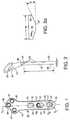
- FIG. 1is a top view of an exemplary bone plate
- FIG. 1Ais a side, cross sectional view of an exemplary bone plate
- FIG. 1Bis a side, cross sectional view of an exemplary bone plate and screw
- FIG. 2is a side view of an exemplary bone plate
- FIG. 2Ais a cross sectional view along the distal portion of an exemplary bone plate
- FIGS. 2B-2Dare end, side, and top views, respectively of an exemplary bone plate
- FIG. 3is a proximal end view of an exemplary bone plate
- FIG. 4is a rotated proximal end view of an exemplary bone plate
- FIG. 4Ais a top view reflecting the rotation axis of FIG. 4 ;
- FIG. 5is a rotated proximal end view of an exemplary bone plate
- FIG. 5Ais a top view reflecting the rotation axis of FIG. 5 ;
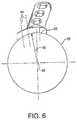
- FIG. 6depicts the cylindrical surface of the bone-contacting surface of an exemplary plate
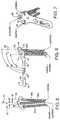
- FIG. 7is a perspective view of an exemplary bone plate with proximal head screws
- FIG. 8is an end view of an exemplary bone plate with proximal head screws
- FIG. 9is a side view of an exemplary bone plate with proximal head screws
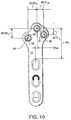
- FIG. 10is a top view of an exemplary bone plate
- FIG. 11is a top view of a relatively larger exemplary bone plate
- FIG. 12is a top view of a relatively larger exemplary bone plate
- FIG. 13is a top perspective view of the top of the articular surface between the tibia and the femur with an exemplary bone plate affixed to the tibia;
- FIG. 14is a side perspective view of an exemplary bone plate affixed to the tibia.
- FIG. 1depicts an exemplary embodiment of the present invention.
- the plate 10has two distinct portions—a lower or distal portion 12 and an upper or proximal portion 14 . These two portions are preferably formed integral to one another, but could be made of two separate portions attached by conventional means. It is most preferred that these two portions be made from the same piece of metal, preferably surgical grade stainless steel, such as 316L implant grade stainless steel.
- the plate 10is designed for attachment to the tibia of an animal, such as a canine, feline, bovine, equine, but more particularly for canines, during a tibial plateau leveling osteotomy procedure.
- the lower or distal portion 12is designed to be affixed to the lower or distal portion of the tibia.
- the upper or proximal portion 14is designed to be affixed to the upper or proximal portion of the tibia that has been cut and repositioned during the procedure.
- the plate 10thus fixes the relative positions of the substantially curvilinear cut and rotated tibial bone segments.
- the plate 10is secured to the tibial bone segments by screws.
- the distal portion 12 for this examplecan be described basically as an elongated shaft, that as shown in FIG. 2 , has a length, L, substantially greater than its depth, D, and its width, W.
- the lower portionhas three screw holes 16 for fixing the plate 10 to the tibia, however more or less screw holes can be used.
- the screw holes 16can be of any design used in the field for fixing plates to bones in animals. Examples of screw hole 16 designs are set forth in U.S. Pat. Nos.
- the holes 16are designed as elongated slots, with the longer axis being parallel to the longitudinal axis of the plate 10 .
- the two outer holes 16define first and second dimensions on bone-contacting surface 22 .
- First dimension, D L (parallel to plate longitudinal axis)is longer than second dimension D Q (perpendicular to longitudinal plate axis).
- the holes 16are preferably dynamic compression screw holes, which promote healing of the bone. These holes can be shaped to have a concave and preferably partially spherical recess 19 defined by first outer periphery 17 defining the cut into the upper surface 20 of the plate 10 , and a second inner periphery 18 that is narrower than the outer periphery 17 in both the parallel and perpendicular directions from the longitudinal plate axis. As seen in FIGS. 1A-1B , it is preferred that hole 16 be designed such that it provides for compression in the direction toward the osteotomy by having an inclined surface 13 at the distal end of the hole 16 such that a bone screw can be positioned to compress the bone toward the osteotomy site when the screw is advanced and makes contact with the inclined surface.
- the hole 16also has a substantially spherical surface 15 opposite the inclined surface 13 .
- the recess 19is dimensioned to receive a bone screw having an underside head portion that is spherical-shaped, or substantially spherical-shaped and where the underside of the screw head is designed to rest upon the recess 19 .
- screws placed in the distal portion of hole 16will have a compression force and screws placed in the middle or proximal portions of the hole 16 will have a neutral compression force. Screws such as cortex and cancellous screws can be used with the holes 16 .
- the distal portion 12 of the plate 10can also contain one or more holes 16 a that is a combination hole defined by walls having a threaded and a non-threaded portion.
- the combination hole 16 ahas a threaded portion 21 that extends over a first angle 23 with respect to at or near the upper surface 20 and a second angle 24 with respect to at or near the bone-contacting surface 22 .
- the first anglepreferably extends between about 170° and 230° and the second angle preferably extends between about 225° and 275°.
- the screw to be used with combination hole 16 acan be a locking or bone, such as a cortex, screw.
- a locking screwhas threads on the underneath side of the head that engage in mating threads in the wall of the hole to lock the screw into place in the plate.
- Use of a locking screwsecures the head of the screw to the plate 10 for maintaining a fixed angular relationship between the locking screw and the plate.
- Cortex screwsare designed to go through relatively harder bone mass and have relatively tighter thread patterns.
- Use of both locking screws and non-locking screwsprovides stability between both the screw and the bone plate and between the bone plate and the bone as described in U.S. Pat. No. 6,623,486, which is hereby incorporated in its entirety by reference.
- the plate 10contains screw holes in the proximal portion 14 to secure the plate 10 to the cut and rotated portion of the tibia.
- These holesare preferably conical shaped holes that are threaded to receive threaded, locking bone screws.
- at least one, and more preferably all, of these holesare designed such that the threads 33 engage threads located on the underneath of the head of the screw, which threads are of a different dimension than those along the shaft of the screw.
- the holes 30 , 31 , 32are preferably designed to be used with locking screws. Although it is preferred that the holes 30 , 31 , 32 be designed to be used with locking screws, these holes can also be designed to be used with any conventional bone screw such as cortex and cancellous screws with any known screw hole design.
- hole 16 acan be a combination hole as described above having threads along a partial portion of the hole wall.
- Representative hole 30is shown as having threads preferably around the 360° circumference of the hole at its lower portion to engage the underside of the head portion 38 of superior screw 30 a.
- the proximal portion 14is pre-bent such that it is contoured to at least partially conform to the anatomy of the tibial bone segment that has been repositioned during the TPLO procedure.
- the proximal portion 14is in a different plane than the distal portion 12 .
- the proximal portion 14be pre-bent or manufactured to fit or contour to the bone anatomy prior to having the screw holes (for example, holes 30 , 31 , 32 ) in the proximal portion 14 machined therein.
- the screw holescan be made to receive locking screws that when screwed into place have a fixed path through the bone structure.
- the present inventionprovides for optimized screw paths for the screws in the proximal portion 14 so that the screws avoid the articular surface and the osteotomy surface.
- the distal portion 12preferably contains recesses 26 defined by walls 26 a so that when the plate is implanted there is a space between the tibia and the plate 10 .
- recessesare disclosed in U.S. Pat. No. 5,002,544, which is hereby incorporated in its entirety by reference for this feature.
- the recesses 26can take various dimensions but are essentially designed to provide a relatively small space between the bone-contacting surface 22 and the bone.
- the recessesare formed by cutting a conical shape into the underside of the plate. As shown in FIG. 2 a , the recesses can be described as forming an angle ⁇ between the bone-contacting surface 22 .
- the anglecan be defined by the beginning point of the recess 27 and its ending point 28 and the plane defined by the bone-contacting surface 22 .
- the anglecan be between about 10° and about 30°.
- the recesses 26are off-set distally from the center of the holes 16 and are preferably located in parallel on both sides of the plate 10 as shown in FIG. 2 a.
- the proximal portion 14 of the plate 10is designed or configured in its dimensions to advantageously contour to the tibial bone segment that has been cut and rotated during the TPLO procedure. This feature can be more readily explained in the preferred embodiment by first defining three orthogonal planes with respect to the plate 10 as shown in FIGS. 2B-2D .
- FIG. 2Bthe plate 10 is viewed from the end of the distal portion 12 longitudinally along its shaft.
- a base plane 42is defined by the flat distal portion 12 at the bone-contacting surface 22 .
- a mid-plane 44is defined as bisecting the base plane in the distal portion 12 of the plate 10 and extending along the length of the plate.
- a transverse plane 46is defined as being orthogonal to the base plane 42 and the mid-plane 44 .
- Center lines 34denote the center axis of the holes 30 , 31 , and 32 . These center lines 34 are preferably off-set from the mid-plane 44 for the proximal portion 14 as described below.
- the center lines 34also depict the targeted screw paths for the locking screws. The targeted screw paths are determined by the threads contained on the walls of the holes 30 , 31 , and 32 that are engaged by the mating threads 38 on the underside of the head of the locking screws as depicted in FIG. 1B .
- the contoured shape of the bone-contacting surface 22 of the proximal portion 14can be more readily viewed by rotating the plate 10 .
- the preferred contour for the bone-contacting surface 22 of the proximal portion 14is that formed by an arc of a cylinder.
- the centerline of the cylindercan be viewed perpendicularly by rotating the plate twice.
- the plate 10can be rotated about 5-15°, preferably about 7-13°, more preferably about 10° in a clock-wise fashion about a first rotation axis 48 that is defined by the intersection of the mid-plane 44 and an off-set transverse plane 46 .
- the result of the first rotationis shown in FIG. 4 and the rotation axis 48 is shown in FIG. 4A .
- FIG. 4As shown in FIG.
- the off-set transverse plane 46 defining first rotation axis 48is located about 18-30 mm, preferably about 21-27 mm, and more preferably about 24 mm distally from the center axis of superior hole 30 and the distance is depicted by line 30 L (where the center axis for hole 30 is defined by the intersection of the hole axis with the top surface of the plate).
- the plate 10is rotated about 15-30°, preferably about 20-25°, and more preferably about 23.5° downward about a second rotation axis 49 defined by the intersection of the off-set, rotated, transverse plane and the base plane 42 .
- the result of the second rotationis shown in FIG. 5 and the rotation axis 49 is shown in FIG. 5A .
- This rotationresults, as shown in FIG. 6 , with the bone-contacting surface 22 of proximal portion 14 being defined by cylinder 29 that has its center axis 40 perpendicular to the page after the rotations.
- the radius 42 of the cylinder 29is about 18 to about 24, preferably about 20 to about 22, and more preferably about 21 mm and thus defines the arched and contoured bone-contacting surface 22 for the proximal portion 14 of the plate 10 .
- the plate 10is also preferably designed to have the screws for the proximal portion 14 angle into the tibia so that the screws are directed away from the articular surface between the tibia and the femur, away from the osteotomy surface of the tibia, and away from the edges of the tibia and into the central mass of the tibia.
- the superior screw hole 30is angled such that the superior screw 30 is angled away from the articular surface where the femur and tibia contact.
- the cranial and caudal screw holesare angled such that the corresponding screws are angled away from the edges of the tibia and away from the cut portion of the tibia from the osteotomy.
- the plate 10is designed to have optimal screw paths for the screws used with the superior 30 , cranial 31 , and caudal 32 screw holes.
- the optimal screw pathsare preferably achieved by first shaping or pre-contouring the proximal portion 14 of the plate 10 to substantially conform to the bone anatomy and then machining the screw holes through the pre-contoured proximal portion 14 .
- the use of a screw hole designed for use with a locking screwresults in the screw path taken by the locking screw being fixed so that the resulting screw path is targeted through a desired section of the tibial bone segment.
- FIGS. 7-9depict one embodiment for the design of these screw paths.
- the superior hole 30is designed such that the center axis 34 for the screw path is angled about 5° from the mid-plane 44 .
- the center axis 34 for the superior hole 30 for the superior screw 30 acan be angled between about 2° and about 10°, and preferably between about 3° and about 7°.
- the cranial hole 31is designed such that its center axis 34 for the cranial screw 31 a is angled about 5° from the mid-plane 44 .
- the center axis 34 for the cranial hole 31 for the cranial screw 31 acan be angled between about 2° and about 10°, and preferably between about 3° and about 7°.
- the caudal hole 32is designed such that its center axis 34 for the caudal screw 32 a is angled about 3° from the mid-plane 44 .
- the center axis 34 for the caudal hole 32 for the caudal screw 32 acan be angled between about 1° and about 7°, and preferably between about 2° and about 5°.
- the proximal portion 14 screw holes 30 , 31 , 32can also be angled such that the superior 30 a , cranial 31 a , and caudal 32 a screws are not perpendicular to the base plane 42 .
- the advantage for such a designis to angle the screws so that they enter an area of greater bone mass in the tibial bone segment that was cut and rotated during the TPLO procedure.
- the superior hole 30is designed such that the center line 34 for the hole is at an angle of about 93° to the base plane 42 . This results in the superior screw 30 a being angled distally or inwardly toward the center of the proximal portion 14 of the plate 10 .
- the superior hole 30can be designed such that its center line 34 is at an angle of between about 91° and about 97°, preferably between about 92° and about 95° from the base plane 42 , but it can also be at an angle of 90°.
- the cranial 31 and caudal 32 holesare at an angle of 90°, or perpendicular, to the base plane 42 , however either or both of these holes can be designed such that their center lines 34 are at an angle between about 85° and about 89°.
- the proximal portion 14 of the platepreferably contains three screws, however the plate can be designed with more or less screws, such as 2-4 proximal-head screws. It is preferred that the cranial screw hole 31 and caudal screw hole 32 be positioned distally from the superior screw hole 30 . All screw hole dimensions are taken from the points defined by the intersection of the hole axis with the top surface of the plate as depicted by axis points 35 as shown in FIG. 10 .
- the center of cranial screw hole 31will be positioned a distance of between about 3.5 mm and about 6 mm, preferably about 4 mm to about 5.5 mm, and more preferably about 4.5-5 mm distally from superior hole 30 and parallel to mid-plane 44 as shown by line 30 - 31 L .
- the center of caudal screw hole 32will be positioned a distance of between about 6 mm to about 9 mm, preferably about 7 mm to about 8 mm, and more preferably about 7.3-7.7 mm distally from the superior hole 30 and parallel to mid-plane 44 as shown by line 30 - 32 L .
- the head portion 14 screw holescan also be positioned off of the mid-plane 44 .
- Superior screw hole 30can have its center positioned either on the mid-plane 44 , or preferably it is positioned between about 0.5 mm and about 3 mm, preferably about 1.2 to about 2.4 mm, and more preferably about 1.6-2 mm perpendicularly and cranially from the mid-plane 44 as shown by line 30 W .
- the cranial screw hole 31is preferably positioned such that its center is between about 4 mm and about 6.5 mm, preferably between about 4.5 mm and about 6 mm, and more preferably about 5-5.5 mm perpendicularly and cranially from the superior hole 30 as shown by line 30 - 31 W
- the caudal screw hole 32is preferably positioned such that its center is between about 5 mm and about 9 mm, preferably between about 6 and about 8 mm, and more preferably about 6.5-7.5 mm perpendicularly and caudally from the superior hole 30 as shown by line 30 - 32 W .
- the plate 10has been described in its preferred embodiment as sized to be used with medium to large canines.
- the plateis designed to be preferably used with 3.5 mm bone screws and has a distal portion 12 width W of between about 9-14 mm, preferably about 10-13 mm. more preferably 11-12 mm.
- the plate 10can be adjusted to fit various anatomies.
- the platecan be downsized to fit smaller animals, such as smaller canines.
- the platecan be designed for its screw holes 16 to accommodate 2.7 mm bone screws.
- the width of such a platecan be between about 5-10 mm, preferably 6-9 mm, and more preferably 7-8 mm.
- the radius 42 for the cylinder 29 defining the bone-contacting surface 22 for the proximal portion 14 of the plateis between about 13.5 and about 18 mm, preferably 14.5 and 17 mm, and more preferably 15.5 and 16 mm.
- the first rotation axis 48 for this sized platecan be located about 13 to about 21 mm, preferably between about 15 to about 19 mm, more preferably about 17 mm distally from the center axis of the superior hole 30 .
- the angles for rotation for viewing the center axis of cylinder 29 perpendicular to the pageare the same for the first rotation as described above, but for the second rotation the angle is between about 18-26°, preferably between about 20-24°, and more preferably about 22°.
- the smaller 2.7 mm platecan be designed to have its proximal portion 14 screw holes located in a similar pattern as with the 3.5 mm plate. As before, all screw hole dimensions are taken from the points defined by the intersection of hole axis with the top surface of the plate as depicted by axis points 35 . As shown in FIG. 10 , preferably the center of cranial screw hole 31 will be positioned a distance of between about 2 mm and about 4 mm, preferably about 2.5 mm to about 3.5 mm, and more preferably about 3 mm distally from superior hole 30 and parallel to mid-plane 44 as shown by line 30 - 31 L .
- the center of caudal screw hole 32will be positioned a distance of between about 4 mm to about 7 mm, preferably about 5.5 mm to about 6.5 mm, and more preferably about 5-6 mm distally from superior hole 30 and parallel to mid-plane 44 as shown by line 30 - 34 .
- the head portion 14 screw holescan also be positioned off-set from the mid-plane 44 .
- Superior screw hole 30can have its center positioned either on the mid-plane 44 , or preferably it is positioned between about 0 mm and about 2.5 mm, preferably about 0 and about 1.5 mm, and more preferably about 0.5 mm perpendicularly and cranially from the mid-plane 44 as shown by line 30 W .
- the cranial screw hole 31is preferably positioned such that its center is between about 2.5 mm and about 5.5 mm, preferably between about 3.5 mm and about 4.5 mm, and more preferably about 3.7-4.3 mm perpendicularly and cranially from the superior hole 30 as shown by line 30 - 31 W
- the caudal screw hole 32is preferably positioned such that its center is between about 3 mm and about 6 mm, preferably between about 4.5 and about 5.5 mm, and more preferably about 4-5 mm perpendicularly and caudally from the superior hole 30 as shown by line 30 - 32 W .
- the plate 10has a design to accommodate a larger plate structure for use with larger animals.
- the plate 10has a distal portion 12 that is slightly wider, having a width between about 12 and about 15 mm, preferably between about 12 and about 13.5 mm wide.
- the distal portion 12can have more than three screw holes and is shown here with four screw holes 16 , two of which are combination screw holes 16 a , however all of these holes 16 can be either combination screw holes, oblong screw holes 16 , conical screw holes, or any combination of conical, oblong or combination holes.
- the screw holescan be aligned with the mid-plane 44 of the plate 10 or some or all can be off-set as depicted.
- the proximal portion 14can be designed to accommodate various screw holes, here depicted as four screw holes. These screw holes can be for locking screws as described above.
- the proximal portion 14can be pre-bent to contour to the tibial bone segment cut and rotated during the TPLO procedure.
- the location of the cylindrical surface defining the bone contacting surface 22 for the proximal portion 14can be defined as above through the two angles of rotation.
- the starting axis 48 for the rotation for this size platecan be as described above, but located between about 25 and 38 mm, preferably between about 28 and about 35 mm, more preferably about 31-32 mm distally from the center axis of the superior hole 50 .
- the first rotationcan be in the same amount as described above, and the second rotation can be between about 10-25°, preferably between about 15-20°, and more preferably about 18°.
- the radius 40 of the cylinder 29can be from about 20-32 mm, preferably about 23-29 mm, more preferably about 25-27 mm.
- the four screw holes in the proximal portion 12can be defined as a superior hole 50 , a cranial hole 51 , a caudal hole 52 , and a distal hole 53 . These holes can also be located off of the plate mid-plane 44 and preferably the superior hole 50 is located between 0 and 5 mm, preferably 1.5-4 mm, and more preferably 2-3 mm cranially from the mid-plane 44 .
- the cranial hole 51can be located between about 3.5-11.5 mm, preferably about 5.5-9.5 mm, and more preferably about 7-8 mm distally from the superior hole 50 as shown by line 50 - 51 L .
- the caudal hole 52can be located between about 5.5-13.5 mm, preferably about 7.5-11.5 mm, and more preferably about 9-10 mm distally from the superior hole 50 as shown by line 50 - 52 L .
- the distal hole 53can be located between about 5.5-13.5 mm, preferably about 7.5-11.5 mm, and more preferably about 9-10 mm distally from the superior hole 50 as shown by line 50 - 53 L .
- the cranial hole 51can be located between about 2-10 mm, preferably about 4-8 mm, and more preferably about 5-7 mm cranially from the superior hole 50 as shown by line 50 - 51 W .
- the caudal hole 52can be located between about 5.5-15.5 mm, preferably about 8-12 mm, and more preferably about 10-11 mm caudally from the superior hole 50 as shown by line 50 - 52 W .
- the distal hole 53can be located between about 0-4 mm, preferably about 1-3 mm, and more preferably about 1.5-2 mm caudally from the superior hole 50 as shown by line 50 - 53 W .
- the bone plate 10can be used in a TPLO procedure as well known in the art. Generally, the tibia will be cut in a curved fashion and rotated. The cut and rotated portion can then be joined to the lower or distal portion of the tibia by use of the bone plate 10 .
- the plate 10can be secured to the distal and cut/rotated segments of the tibia by securing bone screws to the bone segments through the screw holes on the plate.
- the bone platecan be supplied with the mating screws in the form of a kit.
- the pre-contoured plate of the present inventionprovides various benefits.
- the plateis designed to be pre-fitted or contoured to the specific bone anatomy.
- the plateis also designed such that after the proximal portion is pre-contoured, the screw holes for the proximal portion are machined through the plate. These screw holes are preferably designed for use with locking screws. When the locking screws are secured through the plate and into the tibial bone segment, their screw path is pre-targeted to advantageously avoid the articular surface between the tibia and the femur, to avoid the osteotomy surface, and to avoid the outer edge or surface of the tibia.
- the superior screw 30 ais designed to have a targeted screw path that is angled downward slightly, distally, away from the articular surface 60 between the proximal, cut segment 66 of the tibia 64 and the femur 68 .
- the superior screw 30 ais also shown as being angled slightly caudally to avoid the outer edge 70 of the tibia.
- the cranial screw 31 ais shown as being angled slightly caudally toward the center of the tibia and away from the osteotomy edge 62 of the tibia.
- the caudal screw 32 ais shown as being angled slightly cranially toward the center of the tibia and away from the outer edge 70 of the tibia. As shown in FIG. 14 , the plate 10 is secured to the distal portion of the tibia 64 and to the osteotomy cut segment 66 of the tibia.
Landscapes
- Health & Medical Sciences (AREA)
- Orthopedic Medicine & Surgery (AREA)
- Surgery (AREA)
- Life Sciences & Earth Sciences (AREA)
- Molecular Biology (AREA)
- Public Health (AREA)
- Engineering & Computer Science (AREA)
- Biomedical Technology (AREA)
- Heart & Thoracic Surgery (AREA)
- Medical Informatics (AREA)
- Neurology (AREA)
- Animal Behavior & Ethology (AREA)
- General Health & Medical Sciences (AREA)
- Nuclear Medicine, Radiotherapy & Molecular Imaging (AREA)
- Veterinary Medicine (AREA)
- Surgical Instruments (AREA)
- Piles And Underground Anchors (AREA)
- Continuous Casting (AREA)
- Fertilizing (AREA)
- Prostheses (AREA)
- Diaphragms For Electromechanical Transducers (AREA)
- Table Devices Or Equipment (AREA)
Abstract
Description
Claims (22)
Priority Applications (5)
| Application Number | Priority Date | Filing Date | Title |
|---|---|---|---|
| US13/538,407US10786290B2 (en) | 2006-02-24 | 2012-06-29 | Tibial plateau leveling osteotomy plate |
| US16/031,792US10905479B2 (en) | 2006-02-24 | 2018-07-10 | Tibial plateau leveling osteotomy plate |
| US29/656,918USD852957S1 (en) | 2006-02-24 | 2018-07-17 | Tibial plateau leveling osteotomy plate |
| US16/947,435US11026728B2 (en) | 2006-02-24 | 2020-07-31 | Tibial plateau leveling osteotomy plate |
| US17/301,824US11992250B2 (en) | 2006-02-24 | 2021-04-15 | Tibial plateau leveling osteotomy plate |
Applications Claiming Priority (2)
| Application Number | Priority Date | Filing Date | Title |
|---|---|---|---|
| US11/361,245US8523921B2 (en) | 2006-02-24 | 2006-02-24 | Tibial plateau leveling osteotomy plate |
| US13/538,407US10786290B2 (en) | 2006-02-24 | 2012-06-29 | Tibial plateau leveling osteotomy plate |
Related Parent Applications (1)
| Application Number | Title | Priority Date | Filing Date |
|---|---|---|---|
| US11/361,245ContinuationUS8523921B2 (en) | 2006-02-24 | 2006-02-24 | Tibial plateau leveling osteotomy plate |
Related Child Applications (1)
| Application Number | Title | Priority Date | Filing Date |
|---|---|---|---|
| US16/031,792ContinuationUS10905479B2 (en) | 2006-02-24 | 2018-07-10 | Tibial plateau leveling osteotomy plate |
Publications (2)
| Publication Number | Publication Date |
|---|---|
| US20120265254A1 US20120265254A1 (en) | 2012-10-18 |
| US10786290B2true US10786290B2 (en) | 2020-09-29 |
Family
ID=38291269
Family Applications (6)
| Application Number | Title | Priority Date | Filing Date |
|---|---|---|---|
| US11/361,245Active2030-07-30US8523921B2 (en) | 2006-02-24 | 2006-02-24 | Tibial plateau leveling osteotomy plate |
| US13/538,407Active2026-10-24US10786290B2 (en) | 2006-02-24 | 2012-06-29 | Tibial plateau leveling osteotomy plate |
| US16/031,792Active2026-10-07US10905479B2 (en) | 2006-02-24 | 2018-07-10 | Tibial plateau leveling osteotomy plate |
| US29/656,918ActiveUSD852957S1 (en) | 2006-02-24 | 2018-07-17 | Tibial plateau leveling osteotomy plate |
| US16/947,435ActiveUS11026728B2 (en) | 2006-02-24 | 2020-07-31 | Tibial plateau leveling osteotomy plate |
| US17/301,824Active2027-01-19US11992250B2 (en) | 2006-02-24 | 2021-04-15 | Tibial plateau leveling osteotomy plate |
Family Applications Before (1)
| Application Number | Title | Priority Date | Filing Date |
|---|---|---|---|
| US11/361,245Active2030-07-30US8523921B2 (en) | 2006-02-24 | 2006-02-24 | Tibial plateau leveling osteotomy plate |
Family Applications After (4)
| Application Number | Title | Priority Date | Filing Date |
|---|---|---|---|
| US16/031,792Active2026-10-07US10905479B2 (en) | 2006-02-24 | 2018-07-10 | Tibial plateau leveling osteotomy plate |
| US29/656,918ActiveUSD852957S1 (en) | 2006-02-24 | 2018-07-17 | Tibial plateau leveling osteotomy plate |
| US16/947,435ActiveUS11026728B2 (en) | 2006-02-24 | 2020-07-31 | Tibial plateau leveling osteotomy plate |
| US17/301,824Active2027-01-19US11992250B2 (en) | 2006-02-24 | 2021-04-15 | Tibial plateau leveling osteotomy plate |
Country Status (14)
| Country | Link |
|---|---|
| US (6) | US8523921B2 (en) |
| EP (1) | EP1986557B1 (en) |
| JP (1) | JP5270375B2 (en) |
| KR (1) | KR101342493B1 (en) |
| CN (1) | CN101420918B (en) |
| AT (1) | ATE474514T1 (en) |
| AU (1) | AU2007221344A1 (en) |
| BR (1) | BRPI0710079B8 (en) |
| CA (1) | CA2643131C (en) |
| DE (1) | DE602007007896D1 (en) |
| ES (1) | ES2346710T3 (en) |
| TW (2) | TWI586312B (en) |
| WO (1) | WO2007100513A2 (en) |
| ZA (1) | ZA200807264B (en) |
Cited By (5)
| Publication number | Priority date | Publication date | Assignee | Title |
|---|---|---|---|---|
| USD945623S1 (en) | 2019-09-20 | 2022-03-08 | New Generation Devices, Inc. | Tibial plate |
| USD1018854S1 (en) | 2020-09-21 | 2024-03-19 | Movora, Llc | Tibial plate |
| US12213710B2 (en) | 2019-09-20 | 2025-02-04 | Movora, Llc | Tibial plateau leveling osteotomy plate with offset |
| US12295629B2 (en) | 2019-09-20 | 2025-05-13 | Movora, Llc | Tibial plateau leveling osteotomy plate with offset |
| WO2025155624A1 (en)* | 2024-01-16 | 2025-07-24 | Samuel Patrick Franklin | Device for animal tibial osteotomy stabilization |
Families Citing this family (104)
| Publication number | Priority date | Publication date | Assignee | Title |
|---|---|---|---|---|
| US8105367B2 (en) | 2003-09-29 | 2012-01-31 | Smith & Nephew, Inc. | Bone plate and bone plate assemblies including polyaxial fasteners |
| US8118846B2 (en) | 2005-01-28 | 2012-02-21 | Orthohelix Surgical Designs, Inc. | Orthopedic plates for use in clavicle repair and methods for their use |
| US8118848B2 (en)* | 2005-01-28 | 2012-02-21 | Orthohelix Surgical Designs, Inc. | Orthopedic plate for use in fibula repair |
| US8382807B2 (en) | 2005-07-25 | 2013-02-26 | Smith & Nephew, Inc. | Systems and methods for using polyaxial plates |
| CA2616798C (en) | 2005-07-25 | 2014-01-28 | Smith & Nephew, Inc. | Systems and methods for using polyaxial plates |
| US8523921B2 (en) | 2006-02-24 | 2013-09-03 | DePuy Synthes Products, LLC | Tibial plateau leveling osteotomy plate |
| US8021402B2 (en)* | 2006-03-07 | 2011-09-20 | Orthohelix Surgical Designs, Inc. | Distal radius plate |
| US8267972B1 (en)* | 2006-12-01 | 2012-09-18 | Gehlert Rick J | Bone plate |
| US20090163959A1 (en)* | 2007-11-05 | 2009-06-25 | Deeter Nick A | Rotational osteotomy plating system |
| FR2936700B1 (en) | 2008-10-02 | 2012-04-13 | Memometal Technologies | ORTHOPEDIC IMPLANT IN THE FORM OF A PLATE TO BE FIXED BETWEEN TWO BONE PARTS |
| US20100152783A1 (en)* | 2008-12-11 | 2010-06-17 | Veterinary Implants Direct, Llc | Universal Surgical Plate with 30 Degree Compression Angle |
| US8777998B2 (en)* | 2009-02-23 | 2014-07-15 | Orthopediatrics Corp. | Pediatric long bone support or fixation plate |
| US20100256687A1 (en)* | 2009-04-01 | 2010-10-07 | Merete Medical Gmbh | Fixation Device and Method of Use for a Ludloff Osteotomy Procedure |
| DE102009016394B4 (en) | 2009-04-07 | 2016-02-11 | Merete Medical Gmbh | Device for stable-angle fixation and compression of a fracture site or osteotomy on a bone |
| US8529608B2 (en)* | 2009-04-28 | 2013-09-10 | Osteomed Llc | Bone plate with a transfixation screw hole |
| US8986353B2 (en) | 2009-07-09 | 2015-03-24 | Orthohelix Surgical Designs, Inc. | Osteotomy plate, plate driver and method for their use |
| US10349980B2 (en) | 2009-08-27 | 2019-07-16 | The Foundry, Llc | Method and apparatus for altering biomechanics of the shoulder |
| US9278004B2 (en)* | 2009-08-27 | 2016-03-08 | Cotera, Inc. | Method and apparatus for altering biomechanics of the articular joints |
| US9861408B2 (en) | 2009-08-27 | 2018-01-09 | The Foundry, Llc | Method and apparatus for treating canine cruciate ligament disease |
| US9668868B2 (en) | 2009-08-27 | 2017-06-06 | Cotera, Inc. | Apparatus and methods for treatment of patellofemoral conditions |
| CA2771332C (en) | 2009-08-27 | 2020-11-10 | Cotera, Inc. | Method and apparatus for force redistribution in articular joints |
| US8657859B2 (en)* | 2009-12-16 | 2014-02-25 | Advanced Veterinary Solutions | Implant for promoting stability of the canine stifle joint |
| EP2515779B1 (en) | 2009-12-22 | 2016-03-02 | Merete Medical GmbH | Bone plate system for osteosynthesis |
| US9486262B2 (en)* | 2010-01-27 | 2016-11-08 | DePuy Synthes Products, Inc. | System and method for minimally invasive clavicle plate application |
| JP5996562B2 (en) | 2011-03-04 | 2016-09-21 | シンセス・ゲーエムベーハーSynthes GmbH | Modular hook plate assembly |
| AU2012271441B2 (en) | 2011-06-15 | 2017-02-02 | Smith & Nephew, Inc. | Variable angle locking implant |
| DE202011051165U1 (en) | 2011-08-31 | 2011-11-14 | Merete Medical Gmbh | Anatomically adapted, plantar bone plate and bone plate system |
| FR2980967B1 (en)* | 2011-10-10 | 2013-11-15 | D L P Sarl | OSTEOSYNTHESIS PLATE FOR A TIBIAL OSTEOTOMY TECHNIQUE FOR INTERNAL ADDITIONAL VALUATION |
| KR101401457B1 (en) | 2011-12-09 | 2014-06-10 | 비케이메디텍 (주) | Fixing device |
| DE102012103894B4 (en) | 2012-05-03 | 2016-10-27 | Merete Medical Gmbh | Bone plate system for osteosynthesis |
| US9468466B1 (en) | 2012-08-24 | 2016-10-18 | Cotera, Inc. | Method and apparatus for altering biomechanics of the spine |
| CN102961178A (en)* | 2012-11-20 | 2013-03-13 | 苏州艾迪尔医疗器械有限公司 | Inner side bone fracture plate for tibia far end |
| US9545276B2 (en) | 2013-03-15 | 2017-01-17 | Aristotech Industries Gmbh | Fixation device and method of use for a lapidus-type plantar hallux valgus procedure |
| WO2014147604A2 (en) | 2013-03-19 | 2014-09-25 | Quadrante Do Futuro, Unipessoal Lda | Dynamic osteotomy plate including devices, apparatus and methods using such a plate |
| EP3065656B1 (en)* | 2013-11-05 | 2020-12-23 | Arthrex, Inc. | Tplo plate with suture holes for rotational stability |
| CN103622743B (en)* | 2013-11-28 | 2015-09-16 | 浙江康慈医疗科技有限公司 | Knee joint plateau steel plate |
| USD745162S1 (en) | 2014-01-27 | 2015-12-08 | Merete Medical Gmbh | Bone plate |
| JP6296466B2 (en)* | 2014-03-26 | 2018-03-20 | オリンパステルモバイオマテリアル株式会社 | Bone plate and bone plate system |
| US10226287B2 (en) | 2014-03-31 | 2019-03-12 | Association For The Advancement Of Musculoskeletal | Bone plate with versatile screw holes |
| KR101740905B1 (en)* | 2014-04-18 | 2017-05-29 | 백혜선 | A fixation tool for opening wedge high tibial osteotomy |
| KR101632652B1 (en)* | 2014-04-18 | 2016-07-01 | 백혜선 | A fixation tool for opening wedge high tibial osteotomy |
| US9795425B2 (en) | 2014-06-30 | 2017-10-24 | DePuy Synthes Products, Inc. | Locking web plate |
| US10226288B2 (en) | 2014-11-10 | 2019-03-12 | Biomedtrix, Llc | Osteotomy plate for long bones |
| KR101681556B1 (en)* | 2014-12-03 | 2016-12-01 | 백혜선 | A Fixation Tool for Closed Wedge Distal Femur Osteotomy |
| KR101668110B1 (en)* | 2014-12-16 | 2016-10-20 | 백혜선 | A Fixation Tool Open Wedge Supra-Malleolar(=distal Tibia) Osteotomy |
| ES2987374T3 (en)* | 2015-04-21 | 2024-11-14 | Mwi Veterinary Supply Co | TPLO bone plate |
| US10238438B2 (en) | 2015-04-22 | 2019-03-26 | Flower Orthopedics Corporation | Proximal humeral fracture plate |
| US11076898B2 (en) | 2015-08-27 | 2021-08-03 | Globus Medical, Inc. | Proximal humeral stabilization system |
| US10687874B2 (en) | 2015-08-27 | 2020-06-23 | Globus Medical, Inc | Proximal humeral stabilization system |
| US11197682B2 (en) | 2015-08-27 | 2021-12-14 | Globus Medical, Inc. | Proximal humeral stabilization system |
| GB2557840B (en) | 2015-09-18 | 2021-07-21 | Smith & Nephew Inc | Bone plate |
| US10130402B2 (en) | 2015-09-25 | 2018-11-20 | Globus Medical, Inc. | Bone fixation devices having a locking feature |
| US9974581B2 (en) | 2015-11-20 | 2018-05-22 | Globus Medical, Inc. | Expandable intramedullary systems and methods of using the same |
| US9795411B2 (en) | 2016-03-02 | 2017-10-24 | Globus Medical, Inc. | Fixators for bone stabilization and associated systems and methods |
| US10531905B2 (en) | 2016-04-19 | 2020-01-14 | Globus Medical, Inc. | Implantable compression screws |
| CN109310457B (en) | 2016-05-31 | 2022-05-06 | 奥林巴斯泰尔茂生物材料株式会社 | Bone plate and bone plate system |
| ES2646766B1 (en)* | 2016-06-13 | 2018-09-18 | Alvaro Guillermo Sala Cremades | Fractured bone junction plate |
| US10751098B2 (en) | 2016-08-17 | 2020-08-25 | Globus Medical Inc. | Stabilization systems |
| US11331128B2 (en) | 2016-08-17 | 2022-05-17 | Globus Medical Inc. | Distal radius stabilization system |
| US10420596B2 (en) | 2016-08-17 | 2019-09-24 | Globus Medical, Inc. | Volar distal radius stabilization system |
| US11197701B2 (en) | 2016-08-17 | 2021-12-14 | Globus Medical, Inc. | Stabilization systems |
| US10575884B2 (en) | 2016-08-17 | 2020-03-03 | Globus Medical, Inc. | Fracture plates, systems, and methods |
| US10687873B2 (en) | 2016-08-17 | 2020-06-23 | Globus Medical Inc. | Stabilization systems |
| US11213327B2 (en) | 2016-08-17 | 2022-01-04 | Globus Medical, Inc. | Fracture plates, systems, and methods |
| US10383668B2 (en) | 2016-08-17 | 2019-08-20 | Globus Medical, Inc. | Volar distal radius stabilization system |
| US11432857B2 (en) | 2016-08-17 | 2022-09-06 | Globus Medical, Inc. | Stabilization systems |
| US11141204B2 (en) | 2016-08-17 | 2021-10-12 | Globus Medical Inc. | Wrist stabilization systems |
| US10299847B2 (en) | 2016-09-22 | 2019-05-28 | Globus Medical, Inc. | Systems and methods for intramedullary nail implantation |
| US10610273B2 (en)* | 2016-11-07 | 2020-04-07 | In2Bones Usa, Llc | Bone plate with transverse screw |
| GB201619923D0 (en)* | 2016-11-24 | 2017-01-11 | Vetsos Ltd | Orthopaedic Apparatus |
| US10881438B2 (en) | 2017-03-10 | 2021-01-05 | Globus Medical, Inc. | Clavicle fixation system |
| US10368928B2 (en) | 2017-03-13 | 2019-08-06 | Globus Medical, Inc. | Bone stabilization systems |
| US10905477B2 (en) | 2017-03-13 | 2021-02-02 | Globus Medical, Inc. | Bone stabilization systems |
| US10709566B2 (en) | 2017-05-04 | 2020-07-14 | Wright Medical Technology, Inc. | Implant and method for ankle syndesmosis treatment |
| US12318122B2 (en) | 2017-09-13 | 2025-06-03 | Globus Medical, Inc. | Bone stabilization systems |
| US10856920B2 (en) | 2017-09-13 | 2020-12-08 | Globus Medical Inc. | Bone stabilization systems |
| US11096730B2 (en) | 2017-09-13 | 2021-08-24 | Globus Medical Inc. | Bone stabilization systems |
| TWI659723B (en)* | 2017-11-22 | 2019-05-21 | A Plus Biotechnology Company Limited | Universal osteotomy device |
| PL234637B1 (en)* | 2017-12-30 | 2020-03-31 | Sciencebiotech Spolka Z Ograniczona Odpowiedzialnoscia | Plate for osteotomy |
| US11224468B2 (en) | 2018-03-02 | 2022-01-18 | Globus Medical, Inc. | Distal tibial plating system |
| US11071570B2 (en) | 2018-03-02 | 2021-07-27 | Globus Medical, Inc. | Distal tibial plating system |
| US11141172B2 (en) | 2018-04-11 | 2021-10-12 | Globus Medical, Inc. | Method and apparatus for locking a drill guide in a polyaxial hole |
| KR102210953B1 (en)* | 2019-01-10 | 2021-02-02 | 충남대학교산학협력단 | A animal bone plate for being implanted into the tibia in cruclate ligament rupture surgery |
| US10864026B2 (en) | 2019-02-08 | 2020-12-15 | Steris Instrument Management Services, Inc. | Tibial fixation plate |
| USD891617S1 (en)* | 2019-02-11 | 2020-07-28 | Paragon 28, Inc. | Bone plate |
| US11202663B2 (en) | 2019-02-13 | 2021-12-21 | Globus Medical, Inc. | Proximal humeral stabilization systems and methods thereof |
| TR201908745A2 (en)* | 2019-06-13 | 2020-12-21 | Efa Veterinerlik Hizmetleri Tic Ltd Sti | FULLY ANATOMIC POLYAXIAL LOCKING DISTAL FEMUR PLATE DESIGNED FOR FOUR-LEGED ANIMALS |
| USD910178S1 (en)* | 2019-06-28 | 2021-02-09 | Paragon 28, Inc. | Bone plate |
| FR3098387B1 (en)* | 2019-07-08 | 2021-07-02 | Novastep | Osteosynthesis plate with an anchoring hole intended to cooperate with an osteosynthesis screw for compression of two bone fragments |
| WO2021016418A1 (en) | 2019-07-23 | 2021-01-28 | Coleman Robert Glen | Tibial plateau leveling osteotomy systems and methods |
| US12185995B2 (en) | 2019-10-09 | 2025-01-07 | Globus Medical, Inc. | Bone stabilization systems |
| USD948719S1 (en) | 2019-10-21 | 2022-04-12 | Laboratoires Bodycad Inc. | Posterior stabilizer for an osteotomy plate |
| US11129627B2 (en) | 2019-10-30 | 2021-09-28 | Globus Medical, Inc. | Method and apparatus for inserting a bone plate |
| US11723647B2 (en) | 2019-12-17 | 2023-08-15 | Globus Medical, Inc. | Syndesmosis fixation assembly |
| USD974562S1 (en)* | 2020-01-08 | 2023-01-03 | Ortho Solutions Holdings Limited | Orthopedic plate |
| USD943100S1 (en) | 2020-02-18 | 2022-02-08 | Laboratoires Bodycad Inc. | Osteotomy plate |
| US11395686B2 (en) | 2020-04-20 | 2022-07-26 | Khay-Yong Saw | Bone fixation plate and method of using thereof |
| EP4161415A4 (en)* | 2020-06-08 | 2024-07-10 | In2Bones USA, LLC | ARCHED PLATE FOR FIXING OSTEOTOMIES AND ARTICLE ARTHRODESES |
| WO2023036803A1 (en)* | 2021-09-10 | 2023-03-16 | Kyon Ag | Apparatus for canine elbow correction |
| US11963847B2 (en)* | 2021-11-03 | 2024-04-23 | DePuy Synthes Products, Inc. | TPLO plate compression system and method |
| US12064150B2 (en) | 2022-01-19 | 2024-08-20 | Globus Medical Inc. | System and method for treating bone fractures |
| EP4514250A2 (en)* | 2022-04-28 | 2025-03-05 | Paragon 28, Inc. | Orthopedic implants, instrument systems and methods of use |
| WO2024074735A1 (en)* | 2022-10-04 | 2024-04-11 | Osteobionix, S.L. | Closing wedge osteotomy plate, in the proximal part of the ulna in pet animals |
| US12402923B2 (en) | 2022-10-04 | 2025-09-02 | DePuy Synthes Products, Inc. | Offset hole for TPLO compression |
Citations (75)
| Publication number | Priority date | Publication date | Assignee | Title |
|---|---|---|---|---|
| FR2405062A1 (en) | 1977-10-10 | 1979-05-04 | Dayan Robert | Surgical repair plate for lower fractures of femur - has concave cross section and enlarged end with staggered countersunk screw holes |
| FR2405705A1 (en) | 1977-10-14 | 1979-05-11 | Dayan Robert | Surgical repair plate for tibia upper end fracture - has elongated length with enlarged head and countersunk for fixing screws |
| FR2406429A1 (en) | 1977-10-21 | 1979-05-18 | Dayan Robert | Surgical repair plate for fracture of lower tibia - has enlarged head with holes for countersunk screws and slot for compression brace |
| USRE31628E (en) | 1966-06-22 | 1984-07-10 | Synthes Ag | Osteosynthetic pressure plate construction |
| US4565191A (en) | 1984-01-12 | 1986-01-21 | Slocum D Barclay | Apparatus and method for performing cuneiform osteotomy |
| US4677973A (en) | 1985-05-28 | 1987-07-07 | Barclay Slocum | Proximal, tibial osteotomy for leveling a tibial plateau |
| US4762122A (en) | 1987-02-06 | 1988-08-09 | Barclay Slocum | Device and method for pelvic osteotomy fixation |
| US4800874A (en) | 1986-07-15 | 1989-01-31 | Vereinigte Edelstahlwerke A.G. | Anatomical bone plate and/or transfixion plate |
| US4867144A (en) | 1986-04-14 | 1989-09-19 | Huta Baildon | Plate for connecting base splinters with bone shafts |
| US4955888A (en) | 1989-07-24 | 1990-09-11 | Slocum D Barclay | Biradial saw |
| US4988350A (en) | 1988-06-24 | 1991-01-29 | Wolfgang Herzberg | Device for reconnecting a broken bone |
| US5002544A (en)* | 1987-12-02 | 1991-03-26 | Synthes (U.S.A.) | Osteosynthetic pressure plate osteosynthetic compression plate |
| US5190544A (en) | 1986-06-23 | 1993-03-02 | Pfizer Hospital Products Group, Inc. | Modular femoral fixation system |
| US5304180A (en) | 1992-01-17 | 1994-04-19 | Slocum D Barclay | Tibial osteotomy fixation plate |
| US5364398A (en) | 1986-06-23 | 1994-11-15 | Pfizer Hospital Products Group, Inc. | Modular femoral fixation system |
| WO1996024295A1 (en) | 1995-02-07 | 1996-08-15 | Jenkins Joseph R Jr | Improved tibial osteotomy system |
| US5578038A (en) | 1992-06-18 | 1996-11-26 | Slocum; D. Barclay | Jig for use in osteotomies |
| US5601553A (en) | 1994-10-03 | 1997-02-11 | Synthes (U.S.A.) | Locking plate and bone screw |
| US5709686A (en) | 1995-03-27 | 1998-01-20 | Synthes (U.S.A.) | Bone plate |
| US5733287A (en)* | 1994-05-24 | 1998-03-31 | Synthes (U.S.A.) | Bone plate |
| US5749872A (en) | 1995-09-08 | 1998-05-12 | Ace Medical Company | Keyed/keyless barrel for bone plates |
| US5752953A (en) | 1997-01-30 | 1998-05-19 | Slocum; Barclay | Method and device for adjusting a long-bone conformation |
| FR2758712A1 (en) | 1997-01-27 | 1998-07-31 | Tornier Sa | Tibial osteotomy plate |
| US5827286A (en) | 1997-02-14 | 1998-10-27 | Incavo; Stephen J. | Incrementally adjustable tibial osteotomy fixation device and method |
| US5868749A (en) | 1996-04-05 | 1999-02-09 | Reed; Thomas M. | Fixation devices |
| US5904684A (en) | 1997-04-16 | 1999-05-18 | Rooks; Robert L. | Device and method for simultaneous bilateral pelvic osteotomies |
| US5938664A (en) | 1998-03-31 | 1999-08-17 | Zimmer, Inc. | Orthopaedic bone plate |
| US5951557A (en) | 1997-12-30 | 1999-09-14 | Luter; Dennis W. | Bone plate |
| US6001099A (en) | 1998-06-08 | 1999-12-14 | Huebner; Randall J. | Bone plate with varying rigidity |
| US6077266A (en) | 1999-01-15 | 2000-06-20 | Medoff; Robert J. | Method of enabling bone screws to be installed at an angle in underlying bone |
| US6093201A (en)* | 1999-01-19 | 2000-07-25 | Ethicon, Inc. | Biocompatible absorbable polymer plating system for tissue fixation |
| US6096040A (en)* | 1996-06-14 | 2000-08-01 | Depuy Ace Medical Company | Upper extremity bone plates |
| US6183475B1 (en) | 1998-12-18 | 2001-02-06 | Sulzer Orthopedics Inc. | Distal femoral osteotomy system and method |
| WO2001019267A1 (en) | 1999-09-13 | 2001-03-22 | Synthes Ag Chur | Bone plate system |
| US6221073B1 (en) | 1999-08-20 | 2001-04-24 | Kinetikos Medical, Inc. | Wrist fusion apparatus and method |
| US6283969B1 (en) | 2000-03-10 | 2001-09-04 | Wright Medical Technology, Inc. | Bone plating system |
| DE10015734A1 (en) | 2000-03-02 | 2001-09-13 | Med Medical Engineering Dev Lt | Screw connection for osteosynthesis, e.g. to fix tibia head plate; has screw with conical head and ring, which can be moved in bearing ring, but is spread by screw head to fix angle of implant |
| US20020045901A1 (en) | 1999-03-09 | 2002-04-18 | Michael Wagner | Bone plate |
| US20020156474A1 (en) | 2001-04-20 | 2002-10-24 | Michael Wack | Polyaxial locking plate |
| WO2003013623A1 (en) | 2001-08-10 | 2003-02-20 | Osteotech, Inc. | Bone plating system and method of use |
| US6669701B2 (en) | 2000-01-27 | 2003-12-30 | Synthes (Usa) | Bone plate |
| WO2004024009A1 (en) | 2001-06-08 | 2004-03-25 | Mayo Foundation For Medical Education And Research | Bone plates |
| US20040116930A1 (en) | 2002-06-10 | 2004-06-17 | O'driscoll Shawn W. | Bone plates |
| US20040167522A1 (en) | 2001-05-28 | 2004-08-26 | Alfred Niederberger | Bone plate |
| US20040193165A1 (en) | 2003-03-27 | 2004-09-30 | Hand Innovations, Inc. | Anatomical distal radius fracture fixation plate and methods of using the same |
| US20040225291A1 (en) | 2003-04-01 | 2004-11-11 | Andy Schwammberger | Implant |
| US20040260291A1 (en) | 2003-06-20 | 2004-12-23 | Jensen David G. | Bone plates with intraoperatively tapped apertures |
| US20050010226A1 (en)* | 2003-05-30 | 2005-01-13 | Grady Mark P. | Bone plate |
| US20050015089A1 (en) | 2003-03-26 | 2005-01-20 | Young Robert Allan | Locking bone plate |
| US20050107796A1 (en) | 2003-09-29 | 2005-05-19 | Darin Gerlach | Bone plates and methods for provisional fixation using same |
| WO2005048888A1 (en) | 2003-11-21 | 2005-06-02 | Enztec Limited | A surgical procedure |
| US20050234458A1 (en) | 2004-04-19 | 2005-10-20 | Huebner Randall J | Expanded stabilization of bones |
| US20050240187A1 (en) | 2004-04-22 | 2005-10-27 | Huebner Randall J | Expanded fixation of bones |
| US6974461B1 (en) | 1999-09-14 | 2005-12-13 | Dietmar Wolter | Fixation system for bones |
| US20060009771A1 (en) | 2000-02-01 | 2006-01-12 | Orbay Jorge L | Bone stabilization system including plate having fixed-angle holes together with unidirectional locking screws and surgeon-directed locking screws |
| US20060129151A1 (en) | 2002-08-28 | 2006-06-15 | Allen C W | Systems and methods for securing fractures using plates and cable clamps |
| US20060149275A1 (en) | 2004-12-14 | 2006-07-06 | Cadmus Calvin M | Apparatus and methods for tibial plateau leveling osteotomy |
| US20060173458A1 (en) | 2004-10-07 | 2006-08-03 | Micah Forstein | Bone fracture fixation system |
| US7090676B2 (en) | 2002-11-19 | 2006-08-15 | Acumed Llc | Adjustable bone plates |
| US7108697B2 (en) | 2002-04-23 | 2006-09-19 | Citieffe S.R.L. | Stabilizing support for opening- and closing-wedge osteotomies |
| US20060241608A1 (en) | 2005-03-31 | 2006-10-26 | Mark Myerson | Plate for fusion of the metatarso-phalangeal joint |
| US20060264949A1 (en) | 2003-11-18 | 2006-11-23 | Georges Kohut | Osteosynthesis plate set |
| US7189237B2 (en) | 2002-11-19 | 2007-03-13 | Acumed Llc | Deformable bone plates |
| US7195633B2 (en) | 2004-01-08 | 2007-03-27 | Robert J. Medoff | Fracture fixation system |
| US20070083204A1 (en) | 2005-09-16 | 2007-04-12 | Sidebotham Christopher G | Multi-purpose bone plate system |
| US20070123886A1 (en) | 2003-11-05 | 2007-05-31 | Koenigsee Implantate U. Inst. Zur Osteosynth. Gmbh | Plate used to stabilise distal radius fractures |
| US20070162016A1 (en) | 2005-10-25 | 2007-07-12 | Matityahu Amir M | Bone fastening assembly and bushing and screw for use therewith |
| US7267678B2 (en) | 2003-09-30 | 2007-09-11 | Robert J. Medoff | Intramedullary implant for fracture fixation |
| WO2007137437A2 (en) | 2006-05-30 | 2007-12-06 | Staeubli Hans Ulrich | Bone plate, in particular for fixing a stepped tibial surgical implant |
| US7335204B2 (en) | 2001-07-17 | 2008-02-26 | Tornier Sa | Osteosynthesis plate for the upper end of the arm bone |
| US20080249573A1 (en) | 2003-03-20 | 2008-10-09 | Stryker Trauma Sa | Bone Connection Device |
| US20080300637A1 (en) | 2005-07-25 | 2008-12-04 | Smith & Nephew, Inc. | Systems and methods for using polyaxial plates |
| EP1986557B1 (en) | 2006-02-24 | 2010-07-21 | Synthes GmbH | Tibial plateau leveling osteotomy plate |
| US8177818B2 (en) | 2005-09-08 | 2012-05-15 | Securos, Inc. | Fixation plate |
| WO2015069728A1 (en) | 2013-11-05 | 2015-05-14 | Arthrex, Inc. | Tplo plate with suture holes for rotational stability |
Family Cites Families (10)
| Publication number | Priority date | Publication date | Assignee | Title |
|---|---|---|---|---|
| USD443060S1 (en)* | 2000-06-01 | 2001-05-29 | Bristol-Myers Squibb Company | Bone plate |
| USD480141S1 (en)* | 2000-06-01 | 2003-09-30 | Steve Benirschke | Bone plate |
| USD458684S1 (en)* | 2001-11-13 | 2002-06-11 | Zimmer, Inc. | Orthopaedic bone plate |
| USD463559S1 (en)* | 2001-11-16 | 2002-09-24 | Zimmer, Inc. | Orthopaedic bone plate |
| USD469533S1 (en)* | 2002-01-17 | 2003-01-28 | Zimmer, Inc. | Orthopaedic bone plate |
| USD469875S1 (en)* | 2002-04-26 | 2003-02-04 | Zimmer, Inc. | Orthopaedic bone plate |
| USD469874S1 (en)* | 2002-04-26 | 2003-02-04 | Zimmer, Inc. | Orthopaedic bone plate |
| TWM252386U (en)* | 2003-12-24 | 2004-12-11 | Wellong Instr Co Ltd | Three-sectioned universal bone plate |
| USD622853S1 (en)* | 2009-02-06 | 2010-08-31 | Osteomed L.P. | Hand bone fracture fixation plate |
| USD630750S1 (en)* | 2009-09-17 | 2011-01-11 | Upex Holdings, Llc | Radial head/neck fracture fixation plate |
- 2006
- 2006-02-24USUS11/361,245patent/US8523921B2/enactiveActive
- 2007
- 2007-02-16TWTW102133085Apatent/TWI586312B/enactive
- 2007-02-16TWTW096105899Apatent/TWI411424B/enactive
- 2007-02-16ATAT07750881Tpatent/ATE474514T1/ennot_activeIP Right Cessation
- 2007-02-16ESES07750881Tpatent/ES2346710T3/enactiveActive
- 2007-02-16JPJP2008556364Apatent/JP5270375B2/enactiveActive
- 2007-02-16WOPCT/US2007/004078patent/WO2007100513A2/enactiveApplication Filing
- 2007-02-16DEDE602007007896Tpatent/DE602007007896D1/enactiveActive
- 2007-02-16EPEP07750881Apatent/EP1986557B1/enactiveActive
- 2007-02-16CNCN2007800137356Apatent/CN101420918B/enactiveActive
- 2007-02-16AUAU2007221344Apatent/AU2007221344A1/ennot_activeAbandoned
- 2007-02-16CACA2643131Apatent/CA2643131C/enactiveActive
- 2007-02-16ZAZA200807264Apatent/ZA200807264B/enunknown
- 2007-02-16BRBRPI0710079Apatent/BRPI0710079B8/enactiveIP Right Grant
- 2008
- 2008-08-22KRKR1020087020674Apatent/KR101342493B1/enactiveActive
- 2012
- 2012-06-29USUS13/538,407patent/US10786290B2/enactiveActive
- 2018
- 2018-07-10USUS16/031,792patent/US10905479B2/enactiveActive
- 2018-07-17USUS29/656,918patent/USD852957S1/enactiveActive
- 2020
- 2020-07-31USUS16/947,435patent/US11026728B2/enactiveActive
- 2021
- 2021-04-15USUS17/301,824patent/US11992250B2/enactiveActive
Patent Citations (87)
| Publication number | Priority date | Publication date | Assignee | Title |
|---|---|---|---|---|
| USRE31628E (en) | 1966-06-22 | 1984-07-10 | Synthes Ag | Osteosynthetic pressure plate construction |
| FR2405062A1 (en) | 1977-10-10 | 1979-05-04 | Dayan Robert | Surgical repair plate for lower fractures of femur - has concave cross section and enlarged end with staggered countersunk screw holes |
| FR2405705A1 (en) | 1977-10-14 | 1979-05-11 | Dayan Robert | Surgical repair plate for tibia upper end fracture - has elongated length with enlarged head and countersunk for fixing screws |
| FR2406429A1 (en) | 1977-10-21 | 1979-05-18 | Dayan Robert | Surgical repair plate for fracture of lower tibia - has enlarged head with holes for countersunk screws and slot for compression brace |
| US4565191A (en) | 1984-01-12 | 1986-01-21 | Slocum D Barclay | Apparatus and method for performing cuneiform osteotomy |
| US4677973A (en) | 1985-05-28 | 1987-07-07 | Barclay Slocum | Proximal, tibial osteotomy for leveling a tibial plateau |
| US4867144A (en) | 1986-04-14 | 1989-09-19 | Huta Baildon | Plate for connecting base splinters with bone shafts |
| US5190544A (en) | 1986-06-23 | 1993-03-02 | Pfizer Hospital Products Group, Inc. | Modular femoral fixation system |
| US5364398A (en) | 1986-06-23 | 1994-11-15 | Pfizer Hospital Products Group, Inc. | Modular femoral fixation system |
| US4800874A (en) | 1986-07-15 | 1989-01-31 | Vereinigte Edelstahlwerke A.G. | Anatomical bone plate and/or transfixion plate |
| US4762122A (en) | 1987-02-06 | 1988-08-09 | Barclay Slocum | Device and method for pelvic osteotomy fixation |
| US5002544A (en)* | 1987-12-02 | 1991-03-26 | Synthes (U.S.A.) | Osteosynthetic pressure plate osteosynthetic compression plate |
| US4988350A (en) | 1988-06-24 | 1991-01-29 | Wolfgang Herzberg | Device for reconnecting a broken bone |
| US4955888A (en) | 1989-07-24 | 1990-09-11 | Slocum D Barclay | Biradial saw |
| US5304180A (en) | 1992-01-17 | 1994-04-19 | Slocum D Barclay | Tibial osteotomy fixation plate |
| US5578038A (en) | 1992-06-18 | 1996-11-26 | Slocum; D. Barclay | Jig for use in osteotomies |
| US5733287A (en)* | 1994-05-24 | 1998-03-31 | Synthes (U.S.A.) | Bone plate |
| US5601553A (en) | 1994-10-03 | 1997-02-11 | Synthes (U.S.A.) | Locking plate and bone screw |
| WO1996024295A1 (en) | 1995-02-07 | 1996-08-15 | Jenkins Joseph R Jr | Improved tibial osteotomy system |
| US5709686A (en) | 1995-03-27 | 1998-01-20 | Synthes (U.S.A.) | Bone plate |
| US5749872A (en) | 1995-09-08 | 1998-05-12 | Ace Medical Company | Keyed/keyless barrel for bone plates |
| US5868749A (en) | 1996-04-05 | 1999-02-09 | Reed; Thomas M. | Fixation devices |
| US5968047A (en) | 1996-04-05 | 1999-10-19 | Reed; Thomas Mills | Fixation devices |
| US6096040A (en)* | 1996-06-14 | 2000-08-01 | Depuy Ace Medical Company | Upper extremity bone plates |
| FR2758712A1 (en) | 1997-01-27 | 1998-07-31 | Tornier Sa | Tibial osteotomy plate |
| US5752953A (en) | 1997-01-30 | 1998-05-19 | Slocum; Barclay | Method and device for adjusting a long-bone conformation |
| US5827286A (en) | 1997-02-14 | 1998-10-27 | Incavo; Stephen J. | Incrementally adjustable tibial osteotomy fixation device and method |
| US5904684A (en) | 1997-04-16 | 1999-05-18 | Rooks; Robert L. | Device and method for simultaneous bilateral pelvic osteotomies |
| US5951557A (en) | 1997-12-30 | 1999-09-14 | Luter; Dennis W. | Bone plate |
| US5938664A (en) | 1998-03-31 | 1999-08-17 | Zimmer, Inc. | Orthopaedic bone plate |
| US20020013587A1 (en) | 1998-03-31 | 2002-01-31 | Robert A. Winquist | Orthopaedic bone plate |
| US6001099A (en) | 1998-06-08 | 1999-12-14 | Huebner; Randall J. | Bone plate with varying rigidity |
| US6183475B1 (en) | 1998-12-18 | 2001-02-06 | Sulzer Orthopedics Inc. | Distal femoral osteotomy system and method |
| US6077266A (en) | 1999-01-15 | 2000-06-20 | Medoff; Robert J. | Method of enabling bone screws to be installed at an angle in underlying bone |
| US6093201A (en)* | 1999-01-19 | 2000-07-25 | Ethicon, Inc. | Biocompatible absorbable polymer plating system for tissue fixation |
| US20020045901A1 (en) | 1999-03-09 | 2002-04-18 | Michael Wagner | Bone plate |
| US6719759B2 (en) | 1999-03-09 | 2004-04-13 | Synthes Ag Chur | Bone plate |
| US6221073B1 (en) | 1999-08-20 | 2001-04-24 | Kinetikos Medical, Inc. | Wrist fusion apparatus and method |
| US20040059335A1 (en) | 1999-09-13 | 2004-03-25 | Synthes (U.S.A.) | Bone plating system |
| WO2001019267A1 (en) | 1999-09-13 | 2001-03-22 | Synthes Ag Chur | Bone plate system |
| US7341589B2 (en) | 1999-09-13 | 2008-03-11 | Synthes (U.S.A.) | Bone plating system |
| US7128744B2 (en) | 1999-09-13 | 2006-10-31 | Synthes (Usa) | Bone plating system |
| US6623486B1 (en)* | 1999-09-13 | 2003-09-23 | Synthes (U.S.A.) | bone plating system |
| US6974461B1 (en) | 1999-09-14 | 2005-12-13 | Dietmar Wolter | Fixation system for bones |
| US6669701B2 (en) | 2000-01-27 | 2003-12-30 | Synthes (Usa) | Bone plate |
| US7695502B2 (en) | 2000-02-01 | 2010-04-13 | Depuy Products, Inc. | Bone stabilization system including plate having fixed-angle holes together with unidirectional locking screws and surgeon-directed locking screws |
| US20060009771A1 (en) | 2000-02-01 | 2006-01-12 | Orbay Jorge L | Bone stabilization system including plate having fixed-angle holes together with unidirectional locking screws and surgeon-directed locking screws |
| DE10015734A1 (en) | 2000-03-02 | 2001-09-13 | Med Medical Engineering Dev Lt | Screw connection for osteosynthesis, e.g. to fix tibia head plate; has screw with conical head and ring, which can be moved in bearing ring, but is spread by screw head to fix angle of implant |
| US6283969B1 (en) | 2000-03-10 | 2001-09-04 | Wright Medical Technology, Inc. | Bone plating system |
| US20020156474A1 (en) | 2001-04-20 | 2002-10-24 | Michael Wack | Polyaxial locking plate |
| US20040167522A1 (en) | 2001-05-28 | 2004-08-26 | Alfred Niederberger | Bone plate |
| US7655029B2 (en) | 2001-05-28 | 2010-02-02 | Synthes Usa, Llc | Bone plate |
| WO2004024009A1 (en) | 2001-06-08 | 2004-03-25 | Mayo Foundation For Medical Education And Research | Bone plates |
| US7335204B2 (en) | 2001-07-17 | 2008-02-26 | Tornier Sa | Osteosynthesis plate for the upper end of the arm bone |
| WO2003013623A1 (en) | 2001-08-10 | 2003-02-20 | Osteotech, Inc. | Bone plating system and method of use |
| US7108697B2 (en) | 2002-04-23 | 2006-09-19 | Citieffe S.R.L. | Stabilizing support for opening- and closing-wedge osteotomies |
| US20040116930A1 (en) | 2002-06-10 | 2004-06-17 | O'driscoll Shawn W. | Bone plates |
| US20060129151A1 (en) | 2002-08-28 | 2006-06-15 | Allen C W | Systems and methods for securing fractures using plates and cable clamps |
| US7090676B2 (en) | 2002-11-19 | 2006-08-15 | Acumed Llc | Adjustable bone plates |
| US7189237B2 (en) | 2002-11-19 | 2007-03-13 | Acumed Llc | Deformable bone plates |
| US20080249573A1 (en) | 2003-03-20 | 2008-10-09 | Stryker Trauma Sa | Bone Connection Device |
| US20050015089A1 (en) | 2003-03-26 | 2005-01-20 | Young Robert Allan | Locking bone plate |
| US7722653B2 (en) | 2003-03-26 | 2010-05-25 | Greatbatch Medical S.A. | Locking bone plate |
| US20040193165A1 (en) | 2003-03-27 | 2004-09-30 | Hand Innovations, Inc. | Anatomical distal radius fracture fixation plate and methods of using the same |
| US20040225291A1 (en) | 2003-04-01 | 2004-11-11 | Andy Schwammberger | Implant |
| US20050010226A1 (en)* | 2003-05-30 | 2005-01-13 | Grady Mark P. | Bone plate |
| US7537596B2 (en) | 2003-06-20 | 2009-05-26 | Acumed Llc | Bone plates with intraoperatively tapped apertures |
| US20040260291A1 (en) | 2003-06-20 | 2004-12-23 | Jensen David G. | Bone plates with intraoperatively tapped apertures |
| US20050107796A1 (en) | 2003-09-29 | 2005-05-19 | Darin Gerlach | Bone plates and methods for provisional fixation using same |
| US7267678B2 (en) | 2003-09-30 | 2007-09-11 | Robert J. Medoff | Intramedullary implant for fracture fixation |
| US20070123886A1 (en) | 2003-11-05 | 2007-05-31 | Koenigsee Implantate U. Inst. Zur Osteosynth. Gmbh | Plate used to stabilise distal radius fractures |
| US20060264949A1 (en) | 2003-11-18 | 2006-11-23 | Georges Kohut | Osteosynthesis plate set |
| WO2005048888A1 (en) | 2003-11-21 | 2005-06-02 | Enztec Limited | A surgical procedure |
| US7195633B2 (en) | 2004-01-08 | 2007-03-27 | Robert J. Medoff | Fracture fixation system |
| US20050234458A1 (en) | 2004-04-19 | 2005-10-20 | Huebner Randall J | Expanded stabilization of bones |
| US20050240187A1 (en) | 2004-04-22 | 2005-10-27 | Huebner Randall J | Expanded fixation of bones |
| US20060173458A1 (en) | 2004-10-07 | 2006-08-03 | Micah Forstein | Bone fracture fixation system |
| US20060149275A1 (en) | 2004-12-14 | 2006-07-06 | Cadmus Calvin M | Apparatus and methods for tibial plateau leveling osteotomy |
| US20060241608A1 (en) | 2005-03-31 | 2006-10-26 | Mark Myerson | Plate for fusion of the metatarso-phalangeal joint |
| US20080300637A1 (en) | 2005-07-25 | 2008-12-04 | Smith & Nephew, Inc. | Systems and methods for using polyaxial plates |
| US8177818B2 (en) | 2005-09-08 | 2012-05-15 | Securos, Inc. | Fixation plate |
| US20070083204A1 (en) | 2005-09-16 | 2007-04-12 | Sidebotham Christopher G | Multi-purpose bone plate system |
| US20070162016A1 (en) | 2005-10-25 | 2007-07-12 | Matityahu Amir M | Bone fastening assembly and bushing and screw for use therewith |
| US7951179B2 (en) | 2005-10-25 | 2011-05-31 | Anthem Orthopaedics Llc | Bone attachment screw |
| EP1986557B1 (en) | 2006-02-24 | 2010-07-21 | Synthes GmbH | Tibial plateau leveling osteotomy plate |
| WO2007137437A2 (en) | 2006-05-30 | 2007-12-06 | Staeubli Hans Ulrich | Bone plate, in particular for fixing a stepped tibial surgical implant |
| WO2015069728A1 (en) | 2013-11-05 | 2015-05-14 | Arthrex, Inc. | Tplo plate with suture holes for rotational stability |
Non-Patent Citations (69)
| Title |
|---|
| AO Development, "New Products from AO Development", News-No. 1, AO Publishing, Jun. 2004, 28 sheets. |
| AO Development, "New Products from AO Development", News—No. 1, AO Publishing, Jun. 2004, 28 sheets. |
| Auer et al., "History of AOVET: the First 40 Years", AO Foundation, 2013, 96 sheets. |
| Ballagas et al., "Pre- and Postoperative Force Plate Analysis of Dogs with Experimentally Transected Cranial Cruciate Ligaments Treated Using Tibial Plateau Leveling Osteotomy", Veterinary Surgery, vol. 33, 2004, pp. 187-190. |
| Begue et al., "Small Fragment Set", Stryker Plating System, No. 982181, Switzerland, 2004, 20 sheets. |
| Bruecker et al., "AOVET North America Course-Advanced Techniques in Small Animal Fracture Management", Lecture Abstract Manual, Hilton Columbus at Easton Hotel, Columbus, Ohio, Apr. 7-10, 2016, 322 sheets. |
| Bruecker et al., "AOVET North America Course—Advanced Techniques in Small Animal Fracture Management", Lecture Abstract Manual, Hilton Columbus at Easton Hotel, Columbus, Ohio, Apr. 7-10, 2016, 322 sheets. |
| Conkling et al., "Comparison of Tibial Plateau Angle Changes after Tibial Plateau Leveling Osteotomy Fixation with Conventional or Locking Screw Technology", Veterinary Surgery, vol. 39, 2010, pp. 475-481. |
| Decision denying VOI's Petition for Inter Partes Review of claims 1-11 of U.S. Pat. No. 8,523,921, USPTO, PTAB, Jan. 21, 2020, 35 sheets. |
| Decision denying VOI's Petition for Inter Partes Review of claims 12-18 of U.S. Pat. No. 8,523,921, USPTO, PTAB, Jan. 22, 2020, 52 sheets. |
| Decision denying VOI's Petition for Inter Partes Review of claims 19-20 of U.S. Pat. No. 8,523,921, USPTO, PTAB, Jan. 22, 2020, 36 sheets. |
| Declaration of Jeffrey N. Peck, DVM, DACVS regarding Claims 1-11, 19, 20 of U.S. Pat. No. 8,523,921, Jul. 11, 2019, 123 sheets. |
| Declaration of Troy D. Drewry regarding Claims 1-11, 19, 20 of U.S. Pat. No. 8,523,921, Jul. 12, 2019, 132 sheets. |
| Degner, "Tibial Plateau Leveling Osteotomy-TPLO", VetSurgery Central, 2006, 8 sheets. |
| Degner, "Tibial Plateau Leveling Osteotomy—TPLO", VetSurgery Central, 2006, 8 sheets. |
| Dejardin, "Tibial Plateau Leveling Osteotomy", Textbook of Small Animal Surgery/[edited by] Douglas Slatter.-3rd ed., Saunders, USA, 2003, pp. 2133-2143. |
| Dejardin, "Tibial Plateau Leveling Osteotomy", Textbook of Small Animal Surgery/[edited by] Douglas Slatter.—3rd ed., Saunders, USA, 2003, pp. 2133-2143. |
| DePuy Synthes Products, Inc. v. Veterinary Orthopedic Implants, Inc., No. 3-18-cv-01342-HES-PDB (M.D. Fla.), Redacted Excerpts from Plaintiffs Infringement Contentions, 5 sheets. |
| Ganesh et al., "Biomechanics of bone-fracture fixation by stiffness-graded plates in comparison with stainless-steel plates", BioMedical Engineering OnLine, Jul. 2005, 4:46, 15 sheets. |
| Gretchen, "Meniscal Injures", Veterinary Clinics of North America: Small Animal Practice, vol. 23, No. 4, Jul. 1993, pp. 831-843. |
| Gruen et al., "Small Fragment Set: Operative Technique", Stryker Plating System, No. LTSFST Rev. 1, USA, 2004, 20 sheets. |
| Harasen, "Tibial Plateau Leveling Osteotomy-Part 1", Canadian Veterinary Journal, vol. 45, Jun. 2004, 2 sheets. |
| Harasen, "Tibial Plateau Leveling Osteotomy-Part 2", Canadian Veterinary Journal, vol. 45, Aug. 2004, 2 sheets. |
| Harasen, "Tibial Plateau Leveling Osteotomy—Part 1", Canadian Veterinary Journal, vol. 45, Jun. 2004, 2 sheets. |
| Harasen, "Tibial Plateau Leveling Osteotomy—Part 2", Canadian Veterinary Journal, vol. 45, Aug. 2004, 2 sheets. |
| Image Processing of Canine Tibia Medial Radius, Jun. 28, 2019, 21 sheets. |
| Ismail et al., "Outcome of Cloverleaf Locking Plate Fixation for Femoral Neck Fractures in Young Adults", Malaysian Orthopaedic Journal 2012, vol. 6, No. 1, pp. 30-34. |
| Jorgensen Laboratories Inc., "JorVet TPLO plate advertisement", ACVS Veterinary Surgery Medical Journal, vol. 34, No. 5, Sep.-Oct. 2005, 2 sheets. |
| Kergosien et al., "Radiographic and Clinical Changes of the Tibial Tuberosity after Tibial Plateau Leveling Osteotomy", Veterinary Surgery, vol. 33, 2004, pp. 468-474. |
| Krishnakanth, "Mechanical Considerations in Fracture Fixation", Queensland University of Technology, Brisbane, Australia, 2012, 192 sheets. |
| Kyon, "Tibial Plateau Leveling Osteotomy", KYON Veterinary Surgical Products, USA, Sep. 2015, 4 sheets. |
| Le, "Biomechanics of Fractures and Fixation", Orthopaedic Trauma Association, 2004, 72 sheets. |
| New Generation Devices, "UCP-Unity Cruciate Plate", New Generation Devices, 2004, 2 sheets. |
| Newton et al., "Textbook of Small Animal Orthopaedics", J. B. Lippincott Company, 1985, 46 sheets. |
| Pacchiana et al., "Surgical and postoperative complications associated with tibial plateau leveling osteotomy in dogs with cranial cruciate ligament rupture: 397 cases (1998-2001)", JAVMA, vol. 222, No. 2, Jan. 15, 2003, pp. 184-193. |
| Palmer, "Understanding tibial plateau leveling osteotomies in dogs", Veterinary Medicine, Jun. 2005, v. 100, No. 6, pp. 426-453. |
| Petition for Inter Partes Review of Claims 1-11 of U.S. Pat. No. 8,523,921, Veterinary Orthopedic Implants, Inc., Jul. 12, 2019, 78 sheets. |
| Petition for Inter Partes Review of Claims 12-18 of U.S. Pat. No. 8,523,921, Veterinary Orthopedic Implants, Inc., Jul. 12, 2019, 72 sheets. |
| Petition for Inter Partes Review of Claims 19 and 20 of U.S. Pat. No. 8,523,921, Veterinary Orthopedic Implants, Inc., Jul. 12, 2019, 75 sheets. |
| Pozzi et al., "Effect of Medical Meniscal Release on Tibial Translation After Tibial Plateau Leveling Osteotomy", Veterinary Surgery, vol. 35, 2006, pp. 486-494. |
| Priddy et al., "Complications with and owner assessment of the outcome of tibial plateau leveling osteotomy for treatment of cranial cruciate ligament rupture in dogs: 193 cases (1997-2001)", JAVMA, vol. 222, No. 12, Jun. 15, 2003, pp. 1726-1732. |
| Reif et al., "Comparison of Tibial Plateau Angles in Normal and Cranial Cruciate Deficient Stifles of Labrador Retrievers", Veterinary Surgery, vol. 32, 2003, pp. 385-389. |
| Reif et al., "Influence of Limb Positioning and Measurement Method on the Magnitude of the Tibial Plateau Angle", Veterinary Surgery, vol. 33, 2004, pp. 368375. |
| Sccuros, Securos Orthopedic Implant Advertisements, ACVS Veterinary Surgery Medical Journal, 2003, 9 sheets. |
| Slatter, "Textbook of Small Animal Surgery"-3rd ed., Elsevier Science, 2003, 13 sheets. |
| Slatter, "Textbook of Small Animal Surgery"—3rd ed., Elsevier Science, 2003, 13 sheets. |
| Slocum et al., "Tibial Plateau Leveling Osteotomy for Repair of Cranial Cruciate Ligament Rupture in the Canine", Veterinary Clinics of North America: Small Animal Practice, vol. 23, No. 4, Jul. 1993, pp. 777-795. |
| Slone et al., "Orthopedic Fixation Devices", RadioGraphics, vol. 11, No. 5, Sep. 1991, 25 pp. 823-847. |
| Smith & Nephew, Inc., "TC-100 Screw & Plating System Catalog", USA, May 1999, 86 sheets. |
| Staubli et al., "TomoFix: a New LCP-Concept for Open Wedge Osteotomy of the Medial Proximal Tibia-Early Results in 92 Cases", Injury, International Journal of the Care of the Injured 34, 2003, 8 sheets. |
| Staubli et al., "TomoFix: a New LCP-Concept for Open Wedge Osteotomy of the Medial Proximal Tibia—Early Results in 92 Cases", Injury, International Journal of the Care of the Injured 34, 2003, 8 sheets. |
| Stoffel et al., "Open Wedge High Tibial Osteotomy: Biomechanical Investigation of the Modified Arthrex Osteotomy Plate (Puddu Plate) and the TomoFix Plate", Clinical Biomechanics 19, 2004, pp. 944-950. |
| Synthes Catalog, 2004, 700 sheets. |
| Synthes Catalog-Part 1, 2002, pp. 1-300. |
| Synthes Catalog—Part 1, 2002, pp. 1-300. |
| Synthes Catalog-Part 2, 2002, pp. 301-595. |
| Synthes Catalog—Part 2, 2002, pp. 301-595. |
| Synthes Veterinary Brochure, Feb. 2004, 12 sheets. |
| Synthes, "Philos + Philos Long. The Anatomic fixation system for the proximal humerus with angular stability. Surgical Technique", Stratec Medical, 2005, 18 sheets. |
| Taljanovic et al., "Fracture Fixation", RadioGrafics, vol. 23, No. 6, 2003, pp. 15691590. |
| Tornkvist et al., "The strength of plate fixation in relation to the No. And spacing of bone screws", Journal of Orthopaedic Trauma, vol. 10, Issue 3, Apr. 1996, 14 sheets. |
| Veterinary Orthopedic Implants, Inc., "Veterinary Orthopedic Implants 2006 Catalog", Veterinary Orthopedic Implants, Inc., 2006, 226 sheets. |
| Veterinary Orthopedic Implants, Inc., "Veterinary Orthopedic Implants Bone Plating Set advertisement", ACVS Veterinary Surgery Medical Journal, vol. 33, No. 1, Jan.-Feb. 2004, 2 sheets. |
| Veterinary Orthopedic Implants, Inc., "Veterinary Orthopedic Implants TPLO Plates advertisement", ACVS Veterinary Surgery Medical Journal, vol. 34, No. 4, Jul.-Aug. 2005, 2 sheets. |
| Veterinary Orthopedic Implants, Inc., "Veterinary Orthopedic Implants Y Plates advertisement", ACVS Veterinary Surgery Medical Journal, vol. 34, No. 6, Nov.-Dec. 2005, 2 sheets. |
| VOI's Supplemental Invalidity Contentions re U.S. Pat. No. 8,523,921, USDC for the Middle District of Florida, Case No. 3:18 -Cv-01342, Sep. 18, 2019, 54 sheets. |
| Warzee et al., "Effect of Tibial Plateau Leveling on Cranial and Caudal Tibial Thrusts in Canine Cranial Cruciate-Deficient Stifles: An In Vitro Experimental Study," Veterinary Surgery, No. 30, 2001, pp. 278-286. |
| Wheeler et al., "In Vitro Effects of Osteotomy Angle and Osteotomy Reduction on Tibial Angulation and Rotation During the Tibial Plateau-Leveling Osteotomy Procedure", Veterinary Surgery, vol. 32, 2003, pp. 371-377. |
| Zimmer, Inc., Warsaw, Ind., Brochures "Zimmer Periarticular Distal Radial Locking Plates Surgical Technique", "Zimmer Periarticular Proximal Humeral Locking Plate Surgical Technique", "Zimmer Periarticular Distal Femoral Locking Plate Surgical Technique", "Zimmer Periarticular Proximal Tibial Locking Plate", "Zimmer Periarticular Distal Tibial Locking Plate", "Zimmer Periarticular Radial Styloid Locking Plate", Copyright 2005, 135 sheets. |
Cited By (6)
| Publication number | Priority date | Publication date | Assignee | Title |
|---|---|---|---|---|
| USD945623S1 (en) | 2019-09-20 | 2022-03-08 | New Generation Devices, Inc. | Tibial plate |
| US12213710B2 (en) | 2019-09-20 | 2025-02-04 | Movora, Llc | Tibial plateau leveling osteotomy plate with offset |
| US12295629B2 (en) | 2019-09-20 | 2025-05-13 | Movora, Llc | Tibial plateau leveling osteotomy plate with offset |
| US12349949B2 (en) | 2019-09-20 | 2025-07-08 | Movora, Llc | Tibial plateau leveling osteotomy plate with offset |
| USD1018854S1 (en) | 2020-09-21 | 2024-03-19 | Movora, Llc | Tibial plate |
| WO2025155624A1 (en)* | 2024-01-16 | 2025-07-24 | Samuel Patrick Franklin | Device for animal tibial osteotomy stabilization |
Also Published As
| Publication number | Publication date |
|---|---|
| EP1986557B1 (en) | 2010-07-21 |
| BRPI0710079B8 (en) | 2021-06-22 |
| US11992250B2 (en) | 2024-05-28 |
| CA2643131A1 (en) | 2007-09-07 |
| AU2007221344A1 (en) | 2007-09-07 |
| JP2009527328A (en) | 2009-07-30 |
| BRPI0710079A2 (en) | 2011-08-02 |
| BRPI0710079B1 (en) | 2020-03-24 |
| TWI586312B (en) | 2017-06-11 |
| US8523921B2 (en) | 2013-09-03 |
| US20210228248A1 (en) | 2021-07-29 |
| TW201402065A (en) | 2014-01-16 |
| KR20080107390A (en) | 2008-12-10 |
| US20120265254A1 (en) | 2012-10-18 |
| KR101342493B1 (en) | 2013-12-17 |
| CN101420918A (en) | 2009-04-29 |
| ATE474514T1 (en) | 2010-08-15 |
| WO2007100513A2 (en) | 2007-09-07 |
| DE602007007896D1 (en) | 2010-09-02 |
| USD852957S1 (en) | 2019-07-02 |
| US10905479B2 (en) | 2021-02-02 |
| US20200360064A1 (en) | 2020-11-19 |
| US20180317984A1 (en) | 2018-11-08 |
| US20070233106A1 (en) | 2007-10-04 |
| ZA200807264B (en) | 2009-11-25 |
| TW200800094A (en) | 2008-01-01 |
| JP5270375B2 (en) | 2013-08-21 |
| CA2643131C (en) | 2014-09-09 |
| ES2346710T3 (en) | 2010-10-19 |
| WO2007100513A3 (en) | 2007-12-13 |
| US11026728B2 (en) | 2021-06-08 |
| CN101420918B (en) | 2013-01-02 |
| EP1986557A2 (en) | 2008-11-05 |
| TWI411424B (en) | 2013-10-11 |
Similar Documents
| Publication | Publication Date | Title |
|---|---|---|
| US11992250B2 (en) | Tibial plateau leveling osteotomy plate | |
| US7604657B2 (en) | Bone fixation plate with complex suture anchor locations | |
| JP5215285B2 (en) | Modular fracture fixation plate system | |
| US9820862B2 (en) | Intramedullary nail and method of use | |
| AU2004277946B2 (en) | Bone plates with hole for interchangeably receiving locking and compression screws | |
| JP4368560B2 (en) | Multi-axis fixed plate | |
| EP1937171B1 (en) | Intramedullary bone plate with sheath | |
| US20250143759A1 (en) | Patella bone plate and methods of fixation | |
| US9186256B2 (en) | Wrist implants and methods | |
| US20120022534A1 (en) | Intramedullary arthrodesis nail and method of use | |
| US20120016366A1 (en) | Proximal Radius Locking Plate | |
| WO2025188587A1 (en) | Veterinary distal femur bone plates |
Legal Events
| Date | Code | Title | Description |
|---|---|---|---|
| AS | Assignment | Owner name:SYNTHES (U.S.A.), PENNSYLVANIA Free format text:ASSIGNMENT OF ASSIGNORS INTEREST;ASSIGNOR:HFSC COMPANY;REEL/FRAME:028503/0788 Effective date:20061017 Owner name:SYNTHES USA, LLC, PENNSYLVANIA Free format text:CHANGE OF NAME;ASSIGNOR:SYNTHES (U.S.A.);REEL/FRAME:028508/0926 Effective date:20081231 Owner name:HFSC COMPANY, PENNSYLVANIA Free format text:ASSIGNMENT OF ASSIGNORS INTEREST;ASSIGNOR:SYNTHES (U.S.A.);REEL/FRAME:028509/0236 Effective date:20060516 Owner name:SYNTHES (U.S.A.), PENNSYLVANIA Free format text:ASSIGNMENT OF ASSIGNORS INTEREST;ASSIGNORS:HORAN, TIMOTHY J.;SCHOLL, CHRISTOPHER H.;TOUHALISKY, DANEEN K.;REEL/FRAME:028509/0220 Effective date:20060515 | |
| AS | Assignment | Owner name:DEPUY SPINE, LLC, MASSACHUSETTS Free format text:ASSIGNMENT OF ASSIGNORS INTEREST;ASSIGNOR:SYNTHES USA, LLC;REEL/FRAME:030358/0945 Effective date:20121230 Owner name:DEPUY SYNTHES PRODUCTS, LLC, MASSACHUSETTS Free format text:CHANGE OF NAME;ASSIGNOR:HAND INNOVATIONS LLC;REEL/FRAME:030359/0036 Effective date:20121231 Owner name:HAND INNOVATIONS LLC, FLORIDA Free format text:ASSIGNMENT OF ASSIGNORS INTEREST;ASSIGNOR:DEPUY SPINE, LLC;REEL/FRAME:030359/0001 Effective date:20121230 | |
| AS | Assignment | Owner name:DEPUY SYNTHES PRODUCTS, INC., MASSACHUSETTS Free format text:CHANGE OF NAME;ASSIGNOR:DEPUY SYNTHES PRODUCTS, LLC;REEL/FRAME:035074/0647 Effective date:20141219 | |
| AS | Assignment | Owner name:HAND INNOVATIONS LLC, FLORIDA Free format text:CORRECTIVE ASSIGNMENT TO CORRECT THE INCORRECT APPL. NO. 13/486,591 PREVIOUSLY RECORDED AT REEL: 030359 FRAME: 0001. ASSIGNOR(S) HEREBY CONFIRMS THE ASSIGNMENT;ASSIGNOR:DEPUY SPINE, LLC;REEL/FRAME:042621/0565 Effective date:20121230 | |
| AS | Assignment | Owner name:DEPUY SPINE, LLC, MASSACHUSETTS Free format text:CORRECTIVE ASSIGNMENT TO CORRECT THE INCORRECT APPLICATION NO. US 13/486,591 PREVIOUSLY RECORDED ON REEL 030358 FRAME 0945. ASSIGNOR(S) HEREBY CONFIRMS THE ASSIGNMENT;ASSIGNOR:SYNTHES USA, LLC;REEL/FRAME:042687/0849 Effective date:20121230 | |
| STCV | Information on status: appeal procedure | Free format text:ON APPEAL -- AWAITING DECISION BY THE BOARD OF APPEALS | |
| STCV | Information on status: appeal procedure | Free format text:BOARD OF APPEALS DECISION RENDERED | |
| STPP | Information on status: patent application and granting procedure in general | Free format text:AMENDMENT / ARGUMENT AFTER BOARD OF APPEALS DECISION | |
| STPP | Information on status: patent application and granting procedure in general | Free format text:DOCKETED NEW CASE - READY FOR EXAMINATION | |
| STPP | Information on status: patent application and granting procedure in general | Free format text:PUBLICATIONS -- ISSUE FEE PAYMENT RECEIVED | |
| STCF | Information on status: patent grant | Free format text:PATENTED CASE | |
| CC | Certificate of correction | ||
| MAFP | Maintenance fee payment | Free format text:PAYMENT OF MAINTENANCE FEE, 4TH YEAR, LARGE ENTITY (ORIGINAL EVENT CODE: M1551); ENTITY STATUS OF PATENT OWNER: LARGE ENTITY Year of fee payment:4 |