US10786235B2 - Method and apparatus for closing a fissure in the annulus of an intervertebral disc, and/or for effecting other anatomical repairs and/or fixations - Google Patents
Method and apparatus for closing a fissure in the annulus of an intervertebral disc, and/or for effecting other anatomical repairs and/or fixationsDownload PDFInfo
- Publication number
- US10786235B2 US10786235B2US15/827,322US201715827322AUS10786235B2US 10786235 B2US10786235 B2US 10786235B2US 201715827322 AUS201715827322 AUS 201715827322AUS 10786235 B2US10786235 B2US 10786235B2
- Authority
- US
- United States
- Prior art keywords
- suture
- anchor
- distal end
- flexible finger
- thumb button
- Prior art date
- Legal status (The legal status is an assumption and is not a legal conclusion. Google has not performed a legal analysis and makes no representation as to the accuracy of the status listed.)
- Active, expires
Links
Images


Classifications
- A—HUMAN NECESSITIES
- A61—MEDICAL OR VETERINARY SCIENCE; HYGIENE
- A61B—DIAGNOSIS; SURGERY; IDENTIFICATION
- A61B17/00—Surgical instruments, devices or methods
- A61B17/04—Surgical instruments, devices or methods for suturing wounds; Holders or packages for needles or suture materials
- A61B17/0401—Suture anchors, buttons or pledgets, i.e. means for attaching sutures to bone, cartilage or soft tissue; Instruments for applying or removing suture anchors
- A—HUMAN NECESSITIES
- A61—MEDICAL OR VETERINARY SCIENCE; HYGIENE
- A61B—DIAGNOSIS; SURGERY; IDENTIFICATION
- A61B17/00—Surgical instruments, devices or methods
- A61B17/04—Surgical instruments, devices or methods for suturing wounds; Holders or packages for needles or suture materials
- A61B17/0469—Suturing instruments for use in minimally invasive surgery, e.g. endoscopic surgery
- A—HUMAN NECESSITIES
- A61—MEDICAL OR VETERINARY SCIENCE; HYGIENE
- A61B—DIAGNOSIS; SURGERY; IDENTIFICATION
- A61B17/00—Surgical instruments, devices or methods
- A61B17/04—Surgical instruments, devices or methods for suturing wounds; Holders or packages for needles or suture materials
- A61B17/0482—Needle or suture guides
- A—HUMAN NECESSITIES
- A61—MEDICAL OR VETERINARY SCIENCE; HYGIENE
- A61B—DIAGNOSIS; SURGERY; IDENTIFICATION
- A61B17/00—Surgical instruments, devices or methods
- A61B17/34—Trocars; Puncturing needles
- A61B17/3472—Trocars; Puncturing needles for bones, e.g. intraosseus injections
- A—HUMAN NECESSITIES
- A61—MEDICAL OR VETERINARY SCIENCE; HYGIENE
- A61F—FILTERS IMPLANTABLE INTO BLOOD VESSELS; PROSTHESES; DEVICES PROVIDING PATENCY TO, OR PREVENTING COLLAPSING OF, TUBULAR STRUCTURES OF THE BODY, e.g. STENTS; ORTHOPAEDIC, NURSING OR CONTRACEPTIVE DEVICES; FOMENTATION; TREATMENT OR PROTECTION OF EYES OR EARS; BANDAGES, DRESSINGS OR ABSORBENT PADS; FIRST-AID KITS
- A61F2/00—Filters implantable into blood vessels; Prostheses, i.e. artificial substitutes or replacements for parts of the body; Appliances for connecting them with the body; Devices providing patency to, or preventing collapsing of, tubular structures of the body, e.g. stents
- A61F2/02—Prostheses implantable into the body
- A61F2/30—Joints
- A61F2/46—Special tools for implanting artificial joints
- A61F2/4603—Special tools for implanting artificial joints for insertion or extraction of endoprosthetic joints or of accessories thereof
- A61F2/4611—Special tools for implanting artificial joints for insertion or extraction of endoprosthetic joints or of accessories thereof of spinal prostheses
- A—HUMAN NECESSITIES
- A61—MEDICAL OR VETERINARY SCIENCE; HYGIENE
- A61N—ELECTROTHERAPY; MAGNETOTHERAPY; RADIATION THERAPY; ULTRASOUND THERAPY
- A61N1/00—Electrotherapy; Circuits therefor
- A61N1/02—Details
- A61N1/04—Electrodes
- A61N1/05—Electrodes for implantation or insertion into the body, e.g. heart electrode
- A61N1/0551—Spinal or peripheral nerve electrodes
- A61N1/0558—Anchoring or fixation means therefor
- A—HUMAN NECESSITIES
- A61—MEDICAL OR VETERINARY SCIENCE; HYGIENE
- A61B—DIAGNOSIS; SURGERY; IDENTIFICATION
- A61B17/00—Surgical instruments, devices or methods
- A61B17/04—Surgical instruments, devices or methods for suturing wounds; Holders or packages for needles or suture materials
- A61B17/0401—Suture anchors, buttons or pledgets, i.e. means for attaching sutures to bone, cartilage or soft tissue; Instruments for applying or removing suture anchors
- A61B2017/0409—Instruments for applying suture anchors
- A—HUMAN NECESSITIES
- A61—MEDICAL OR VETERINARY SCIENCE; HYGIENE
- A61B—DIAGNOSIS; SURGERY; IDENTIFICATION
- A61B17/00—Surgical instruments, devices or methods
- A61B17/04—Surgical instruments, devices or methods for suturing wounds; Holders or packages for needles or suture materials
- A61B17/0401—Suture anchors, buttons or pledgets, i.e. means for attaching sutures to bone, cartilage or soft tissue; Instruments for applying or removing suture anchors
- A61B2017/0414—Suture anchors, buttons or pledgets, i.e. means for attaching sutures to bone, cartilage or soft tissue; Instruments for applying or removing suture anchors having a suture-receiving opening, e.g. lateral opening
- A—HUMAN NECESSITIES
- A61—MEDICAL OR VETERINARY SCIENCE; HYGIENE
- A61B—DIAGNOSIS; SURGERY; IDENTIFICATION
- A61B17/00—Surgical instruments, devices or methods
- A61B17/04—Surgical instruments, devices or methods for suturing wounds; Holders or packages for needles or suture materials
- A61B17/0401—Suture anchors, buttons or pledgets, i.e. means for attaching sutures to bone, cartilage or soft tissue; Instruments for applying or removing suture anchors
- A61B2017/0417—T-fasteners
- A—HUMAN NECESSITIES
- A61—MEDICAL OR VETERINARY SCIENCE; HYGIENE
- A61B—DIAGNOSIS; SURGERY; IDENTIFICATION
- A61B17/00—Surgical instruments, devices or methods
- A61B17/04—Surgical instruments, devices or methods for suturing wounds; Holders or packages for needles or suture materials
- A61B17/0401—Suture anchors, buttons or pledgets, i.e. means for attaching sutures to bone, cartilage or soft tissue; Instruments for applying or removing suture anchors
- A61B2017/042—Suture anchors, buttons or pledgets, i.e. means for attaching sutures to bone, cartilage or soft tissue; Instruments for applying or removing suture anchors plastically deformed during insertion
- A—HUMAN NECESSITIES
- A61—MEDICAL OR VETERINARY SCIENCE; HYGIENE
- A61B—DIAGNOSIS; SURGERY; IDENTIFICATION
- A61B17/00—Surgical instruments, devices or methods
- A61B17/04—Surgical instruments, devices or methods for suturing wounds; Holders or packages for needles or suture materials
- A61B17/0401—Suture anchors, buttons or pledgets, i.e. means for attaching sutures to bone, cartilage or soft tissue; Instruments for applying or removing suture anchors
- A61B2017/0438—Suture anchors, buttons or pledgets, i.e. means for attaching sutures to bone, cartilage or soft tissue; Instruments for applying or removing suture anchors slotted, i.e. having a longitudinal slot for enhancing their elasticity
- A—HUMAN NECESSITIES
- A61—MEDICAL OR VETERINARY SCIENCE; HYGIENE
- A61B—DIAGNOSIS; SURGERY; IDENTIFICATION
- A61B17/00—Surgical instruments, devices or methods
- A61B17/04—Surgical instruments, devices or methods for suturing wounds; Holders or packages for needles or suture materials
- A61B17/0401—Suture anchors, buttons or pledgets, i.e. means for attaching sutures to bone, cartilage or soft tissue; Instruments for applying or removing suture anchors
- A61B2017/0446—Means for attaching and blocking the suture in the suture anchor
- A61B2017/0448—Additional elements on or within the anchor
- A61B2017/0451—Cams or wedges holding the suture by friction
- A—HUMAN NECESSITIES
- A61—MEDICAL OR VETERINARY SCIENCE; HYGIENE
- A61B—DIAGNOSIS; SURGERY; IDENTIFICATION
- A61B17/00—Surgical instruments, devices or methods
- A61B17/04—Surgical instruments, devices or methods for suturing wounds; Holders or packages for needles or suture materials
- A61B17/0401—Suture anchors, buttons or pledgets, i.e. means for attaching sutures to bone, cartilage or soft tissue; Instruments for applying or removing suture anchors
- A61B2017/0446—Means for attaching and blocking the suture in the suture anchor
- A61B2017/0456—Surface features on the anchor, e.g. ribs increasing friction between the suture and the anchor
- A—HUMAN NECESSITIES
- A61—MEDICAL OR VETERINARY SCIENCE; HYGIENE
- A61B—DIAGNOSIS; SURGERY; IDENTIFICATION
- A61B17/00—Surgical instruments, devices or methods
- A61B17/04—Surgical instruments, devices or methods for suturing wounds; Holders or packages for needles or suture materials
- A61B17/0401—Suture anchors, buttons or pledgets, i.e. means for attaching sutures to bone, cartilage or soft tissue; Instruments for applying or removing suture anchors
- A61B2017/0446—Means for attaching and blocking the suture in the suture anchor
- A61B2017/0459—Multiple holes in the anchor through which the suture extends and locking the suture when tension is applied
- A—HUMAN NECESSITIES
- A61—MEDICAL OR VETERINARY SCIENCE; HYGIENE
- A61B—DIAGNOSIS; SURGERY; IDENTIFICATION
- A61B17/00—Surgical instruments, devices or methods
- A61B17/04—Surgical instruments, devices or methods for suturing wounds; Holders or packages for needles or suture materials
- A61B17/0401—Suture anchors, buttons or pledgets, i.e. means for attaching sutures to bone, cartilage or soft tissue; Instruments for applying or removing suture anchors
- A61B2017/0464—Suture anchors, buttons or pledgets, i.e. means for attaching sutures to bone, cartilage or soft tissue; Instruments for applying or removing suture anchors for soft tissue
- A—HUMAN NECESSITIES
- A61—MEDICAL OR VETERINARY SCIENCE; HYGIENE
- A61B—DIAGNOSIS; SURGERY; IDENTIFICATION
- A61B17/00—Surgical instruments, devices or methods
- A61B17/04—Surgical instruments, devices or methods for suturing wounds; Holders or packages for needles or suture materials
- A61B2017/0496—Surgical instruments, devices or methods for suturing wounds; Holders or packages for needles or suture materials for tensioning sutures
- A—HUMAN NECESSITIES
- A61—MEDICAL OR VETERINARY SCIENCE; HYGIENE
- A61B—DIAGNOSIS; SURGERY; IDENTIFICATION
- A61B17/00—Surgical instruments, devices or methods
- A61B17/04—Surgical instruments, devices or methods for suturing wounds; Holders or packages for needles or suture materials
- A61B17/06—Needles ; Sutures; Needle-suture combinations; Holders or packages for needles or suture materials
- A61B2017/06052—Needle-suture combinations in which a suture is extending inside a hollow tubular needle, e.g. over the entire length of the needle
- A—HUMAN NECESSITIES
- A61—MEDICAL OR VETERINARY SCIENCE; HYGIENE
- A61F—FILTERS IMPLANTABLE INTO BLOOD VESSELS; PROSTHESES; DEVICES PROVIDING PATENCY TO, OR PREVENTING COLLAPSING OF, TUBULAR STRUCTURES OF THE BODY, e.g. STENTS; ORTHOPAEDIC, NURSING OR CONTRACEPTIVE DEVICES; FOMENTATION; TREATMENT OR PROTECTION OF EYES OR EARS; BANDAGES, DRESSINGS OR ABSORBENT PADS; FIRST-AID KITS
- A61F2/00—Filters implantable into blood vessels; Prostheses, i.e. artificial substitutes or replacements for parts of the body; Appliances for connecting them with the body; Devices providing patency to, or preventing collapsing of, tubular structures of the body, e.g. stents
- A61F2/02—Prostheses implantable into the body
- A61F2/30—Joints
- A61F2/44—Joints for the spine, e.g. vertebrae, spinal discs
- A61F2/442—Intervertebral or spinal discs, e.g. resilient
- A61F2002/4435—Support means or repair of the natural disc wall, i.e. annulus, e.g. using plates, membranes or meshes
Definitions
- This inventionrelates to the treatment of degenerative disc disease in general, and more particularly to methods and apparatus for closing fissures in the annulus of an intervertebral disc. This invention also relates to methods and apparatus for effecting other anatomical repairs and/or fixations.
- the human spineis a column of articulating vertebrae separated by intervertebral discs. It provides support for the torso, and houses and protects the spinal cord in its spinal canal.
- the human intervertebral discis an oval-shaped to kidney-shaped structure of variable size depending on its location in the spine.
- the outer portion of the discis known as the annulus fibrosus (or anulus fibrosus, annulus fibrosis, anulus fibrosis) or simply “the annulus”.
- the inner portion of the discis known as the nucleus pulposis or simply “the nucleus”.
- the annulusis made up of ten to twenty collagen fiber lamellae.
- the collagen fibers within a given lamellaextend parallel to one another. Successive lamellae have their collagen fibers oriented in alternating directions. About 48 percent of the lamellae are incomplete, but this percentage varies with location and it increases with age. On average, the collagen fibers of a given lamella lie at an angle of about sixty degrees to the vertebral axis line, but this too varies with location.
- the orientations of the lamellaeserve to control vertebral motion (i.e., one half of the lamellae tighten to check motion when the vertebra above or below the disc are turned in either direction).
- the annuluscontains the nucleus.
- the nucleushas a consistency generally similar to that of crabmeat.
- the nucleusserves to transmit and dampen axial loads.
- a high water content(approximately 70-80 percent) assists the nucleus in this function.
- the water contenthas a diurnal variation.
- the nucleusabsorbs water while a person lies recumbent. Activity generates increased axial loads which squeeze water from the disc.
- the nucleuscomprises roughly 50 percent of the entire disc.
- the nucleuscontains cells (chondrocytes and fibrocytes) and proteoglycans (chondroitin sulfate and keratin sulfate).
- the cell density in the nucleusis on the order of 4,000 cells per microliter.
- the intervertebral discchanges, or “degenerates”, with age. As a person ages, the water content of the disc falls from approximately 85 percent at birth to approximately 70 percent in the elderly. The ratio of chondroitin sulfate to keratin sulfate decreases with age, while the ratio of chondroitin 6 sulfate to chondroitin 4 sulfate increases with age. The distinction between the annulus and the nucleus decreases with age. Generally, disc degeneration is painless.
- Premature or accelerated disc degenerationis known as degenerative disc disease.
- a large portion of patients suffering from chronic lower back painare thought to have this condition.
- the nucleus and annulus functionsare compromised.
- the nucleusbecomes thinner and less able to handle compressive loads.
- the annulus fibersbecome redundant as the nucleus shrinks. The redundant annular fibers are less effective in controlling vertebral motion.
- This disc pathologycan result in (i) tears of the annulus (both “full-thickness” tears and “partial-thickness” tears) as abnormal loads are transmitted to the annulus and the annulus is subjected to excessive motion between vertebrae, and (ii) disc herniation (i.e., extrusion of the nucleus) through complete (i.e., full-thickness) annular tears.
- Degenerative disc diseaseis frequently the cause of substantial pain for a patient.
- One group of procedureswhich includes microlumbar discectomy, removes the nucleus or a portion of the nucleus.
- a second group of proceduresdestroys nuclear material.
- This groupincludes Chymopapin (an enzyme) injection, laser discectomy, and thermal therapy (i.e., heat treatment to denature proteins in the nucleus).
- a third group of procedureswhich includes spinal fusion procedures, either removes the disc or effectively eliminates the disc's function by connecting together two or more vertebrae, e.g., by “fusing” the vertebrae together with bone.
- spinal fusion procedurestransmit additional stress to the adjacent discs, which typically results in premature degeneration of the adjacent discs over time.
- the “destructive” nature of current surgical treatments for disc degenerationcan provide substantial pain relief for the patient, but it can also lead to further disc degeneration over time, which can result in new pain for the patient.
- procedures to remove the nucleus or a portion of the nucleus, and procedures to destroy nuclear materialcompromise nucleus function and may exacerbate fissures in the annulus while accessing the nucleus, thereby leading to further disc degeneration.
- spinal fusion procedurescan induce premature disc degeneration in adjacent intervertebral discs.
- disc herniationi.e., the extrusion of nucleus through full-thickness annular tears
- thisis difficult to achieve.
- the first conventional toggle anchoris passed through the annulus and into the nucleus on a first side of a fissure
- the second conventional toggle anchoris passed through the annulus and into the nucleus on a second side of the fissure, and then the cinch line is pulled to draw together the two conventional toggle anchors and thereby close the fissure.
- this systemsuffers from significant drawbacks.
- two pieces of soft tissuemay need to be held in apposition to one another to effect a repair (e.g., so as to close an incision in the skin), or two pieces of cartilage may need to be held in apposition to one another to effect a repair (e.g., so as to close a tear in meniscal cartilage), or two pieces of bone may need to be held in apposition to one another so as to effect a repair (e.g., so as to fuse together bone).
- a repaire.g., so as to close an incision in the skin
- two pieces of cartilagemay need to be held in apposition to one another to effect a repair (e.g., so as to close a tear in meniscal cartilage)
- two pieces of bonemay need to be held in apposition to one another so as to effect a repair (e.g., so as to fuse together bone).
- a piece of soft tissuemay need to be held in apposition to bone to effect a repair (e.g., so as to attach soft tissue to bone), or a piece of cartilage may need to be held in apposition to bone to effect a repair (e.g., so as to attach labrum to bone or to attach meniscal cartilage to bone).
- a prosthesismay need to be held in apposition to soft tissue or bone, or soft tissue or bone may need to be held in apposition to a prosthesis, and/or any first object may need to be held in apposition to any second object.
- the present inventionprovides a new and improved method and apparatus for closing fissures in the annulus of an intervertebral disc, whereby to treat degenerative disc disease.
- the present inventionalso provides a new and improved method and apparatus for effecting other anatomical repairs and/or fixations.
- the present inventionfacilitates the reconstruction of the annulus by providing a novel method and apparatus for closing fissures in the annulus of an intervertebral disc.
- such reconstructionprevents recurrent herniation following a microlumbar discectomy.
- the inventionmay also be used in the treatment of herniated discs, annular tears of the disc, and/or other disc degeneration, while enabling surgeons to preserve (or even augment or replace) the contained nucleus.
- the method and apparatus of the present inventionmay be used to treat discs throughout the spine, including the cervical, thoracic, and lumbar spines of humans and animals.
- Preferred embodiments of the present inventioninclude a flexible longitudinal fixation component (e.g., a filament) extending across a soft tissue defect, such as a fissure in the annulus.
- a pair of transverse anchor componentse.g., bar anchors
- the flexible longitudinal fixation componentare preferably placed behind an inner layer of the annulus on opposite sides of the fissure, so as to anchor the flexible longitudinal fixation component to the annulus, with the flexible longitudinal fixation component extending axially through the annulus and laterally across the fissure so as to hold the fissure closed, whereby to prevent nucleus material from passing out the fissure and pressing on the adjacent nerves, including the spinal cord.
- the transverse anchor componentscan be passed through the annulus and into the nucleus of the intervertebral disc using a direct “needle plunge” action, which facilitates passage through the tough, thick annulus, and which is highly compatible with the limited access corridors often imposed on the surgeon.
- the present inventionallows the tension of the flexible longitudinal fixation component to be adjusted as necessary so as to effect proper fissure closure, and then set in place without requiring the use of knots.
- the flexible longitudinal fixation componente.g., the filament
- the flexible longitudinal fixation componentmay be anchored to one of the upper and lower vertebral bodies adjacent to the intervertebral disc being treated.
- two novel transverse anchor componentse.g., bar anchors
- One novel anchor component(sometimes hereinafter referred to as the distal anchor) is provided with an associated inserter and the two, in conjunction with the flexible longitudinal fixation component (e.g., filament) provide enhanced toggling of the anchor component within dense structures such as a vertebral body and/or an intervertebral disc.
- the second novel anchor component(sometimes hereinafter referred to as the proximal anchor) is provided with novel means for knotlessly securing the flexible longitudinal fixation component to that anchor component, whereby to allow the tension of the flexible longitudinal fixation component to be reliably set between the two anchor components without requiring the use of knots.
- the present inventionmay also be used to effect other anatomical repairs and/or fixations.
- the present inventionmay be used to hold two pieces of soft tissue in apposition to one another to effect a repair (e.g., so as to close an incision in the skin), or the present invention may be used to hold two pieces of cartilage in apposition to one another to effect a repair (e.g., so as to close a tear in meniscal cartilage), or the present invention may be used to hold two pieces of bone in apposition to one another so as to effect a repair (e.g., so as to fuse together bone).
- a repaire.g., so as to close an incision in the skin
- cartilagee.g., so as to close a tear in meniscal cartilage
- the present inventionmay be used to hold two pieces of bone in apposition to one another so as to effect a repair (e.g., so as to fuse together bone).
- the present inventionmay be used to hold a piece of soft tissue in apposition to bone to effect a repair (e.g., so as to attach soft tissue to bone), or the present invention may be used to hold a piece of cartilage in apposition to bone to effect a repair (e.g., so as to attach labrum to bone or to attach meniscal cartilage to bone).
- the present inventionmay be used to hold a prosthesis in apposition to soft tissue or bone, or to hold soft tissue or bone in apposition to a prosthesis, and/or to hold any first object in apposition to any second object.
- apparatus for attaching a first object to a second objectcomprising:
- a distal anchorcomprising a generally cylindrical body, a distal end and a proximal end, wherein said distal end comprises an inclined distal end surface, and a vertical bore extending through said generally cylindrical body, perpendicular to the longitudinal axis of said generally cylindrical body;
- a proximal anchorcomprising a generally cylindrical body, a distal end and a proximal end, a top surface and a bottom surface, a first vertical bore extending through said generally cylindrical body from said top surface to said bottom surface, perpendicular to the longitudinal axis of the generally cylindrical body, a second vertical bore spaced distally from said first vertical bore and extending from said top surface to said bottom surface parallel to said first vertical bore, a third vertical bore spaced distally from said second vertical bore and extending from said top surface to said bottom surface parallel to said first vertical bore, and a fourth vertical bore spaced distally from said third vertical bore and extending from said top surface to said bottom surface parallel to said first vertical bore; and
- a suturehaving a proximal end and a distal end, with an enlargement formed at said distal end, wherein said suture extends through said vertical bore of said distal anchor, through said fourth vertical bore of said proximal anchor, through said third vertical bore of said proximal anchor, through said second vertical bore of said proximal anchor and through said first vertical bore of said proximal anchor.
- a method for connecting a first object to a second objectcomprising:
- providing apparatuscomprising:
- apparatus for attaching a suture to an objectcomprising:
- an anchorcomprising a generally cylindrical body, a distal end and a proximal end, wherein said distal end comprises an inclined distal end surface, and a vertical bore extending through said generally cylindrical body, perpendicular to the longitudinal axis of said generally cylindrical body;
- a suturehaving a proximal end and a distal end, with an enlargement formed at said distal end, wherein said suture extends through said vertical bore of said anchor.
- a method for attaching a suture to an objectcomprising:
- providing apparatuscomprising:
- apparatus for attaching a suture to an objectcomprising:
- an anchorcomprising a generally cylindrical body, a distal end and a proximal end, a vertical bore extending through said generally cylindrical body, perpendicular to the longitudinal axis of said generally cylindrical body, a recess formed on one side of said generally cylindrical body and a U-shaped slot formed on the opposing side of said generally cylindrical body whereby to form a flexible finger extending distally within said generally cylindrical body, and further wherein said distal end of said finger is spaced from an opposing portion of said generally cylindrical body;
- providing apparatuscomprising:
- apparatus for attaching a suture to an objectcomprising:
- an anchorcomprising a body having a distal end and a proximal end, and a vertical bore extending through said body substantially perpendicular to the longitudinal axis of said body;
- said anchorfurther comprises a recess formed on one side of said body and a U-shaped slot formed on the opposing side of said body, whereby to form a flexible finger extending distally within said body, and further wherein said distal end of said finger is spaced from an opposing portion of said body;
- At least one of said flexible finger and said bodycomprises a cutout extending therethrough, with said cutout cooperating with said U-shaped slot and said recess so as to together form a suture loading hole extending through said body, with said suture loading hole being sized to receive a suture therein.
- providing apparatuscomprising:
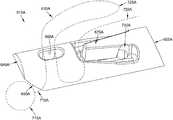
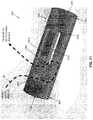
- FIGS. 1 and 2are schematic views showing a novel system for closing a fissure in the annulus of an intervertebral disc, whereby to treat degenerative disc disease, and/or for effecting other anatomical repairs and/or fixations;
- FIG. 3is a schematic view showing the anchor assembly of the novel system of FIGS. 1 and 2 ;
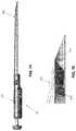
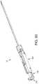
- FIG. 4is a schematic view showing the inserter of the novel system of FIGS. 1 and 2 ;
- FIGS. 5-25are schematic views showing further details of the anchor assembly of FIG. 3 ;
- FIGS. 26, 27, 27A and 28-31are schematic views showing further details of the inserter of FIG. 4 ;
- FIGS. 32-38 and 38A-38Gare schematic views showing use of the novel system of FIGS. 1 and 2 to close a fissure in the annulus of an intervertebral disc;
- FIGS. 39-41are schematic views showing a tensioner which may be used in conjunction with the novel system of FIGS. 1 and 2 ;
- FIGS. 41A and 41Bare schematic views showing another form of tensioner which may be used in conjunction with the novel system of FIGS. 1 and 2 ;
- FIGS. 42-51are schematic views showing examples of additional anatomical repairs and/or fixations which may be effected using the present invention.
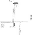
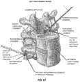
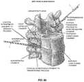
- FIG. 52is a schematic view showing a sensory nerve stimulator (SNS) lead positioned within a spine;
- SNSsensory nerve stimulator
- FIGS. 53-62are schematic views showing how the novel system may be used to hold an SNS lead in position within anatomy
- FIGS. 63-70are schematic views showing various ways in which the novel system may be used to secure an SNS lead adjacent to spinal structures;
- FIGS. 71 and 72are schematic views showing a proximal anchor comprising a flexible finger
- FIG. 73is a schematic view showing a single anchor system formed in accordance with the present invention.
- FIGS. 74-85are schematic views showing another single anchor system formed in accordance with the present invention, wherein the system comprises an anchor comprising a flexible finger;
- FIG. 86is a schematic view showing an alternative form of inserter with impulse driver
- FIGS. 87-92are schematic views showing another single anchor system formed in accordance with the present invention, wherein the system comprises an anchor comprising a flexible finger;
- FIGS. 93-97are schematic views showing another form of stop for selectively preventing deployment of an anchor from an inserter.
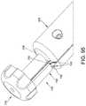
- FIG. 98is a schematic view showing yet another form of stop for selectively preventing deployment of an anchor from an inserter.
- the present inventioncomprises the provision and use of a novel system for closing a fissure in the annulus of an intervertebral disc, whereby to treat degenerative disc disease.
- the present inventionalso provides a new and improved method and apparatus for effecting other anatomical repairs and/or fixations.
- System 5for, among other things, closing a fissure in the annulus of an intervertebral disc.
- System 5generally comprises an anchor assembly 10 ( FIGS. 1-3 ) and an inserter 15 ( FIGS. 1, 2 and 4 ).
- anchor assembly 10generally comprises a distal anchor 20 , a proximal anchor 25 , and a suture 30 connecting distal anchor 20 and proximal anchor 25 .
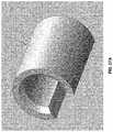
- distal anchor 20comprises a generally cylindrical body 35 having a distal end 40 , a proximal end 45 and a generally circular side wall 50 .
- Distal end 40terminates in a flat distal surface 55 and an inclined distal surface 60 .
- Flat distal surface 55is preferably sufficiently large to render distal end 40 of distal anchor 20 substantially blunt.
- Inclined distal surface 60is pitched at an appropriate angle (e.g., 30 degrees, 45 degrees, etc.) so as to cause distal anchor 20 to turn during deployment, as will hereinafter be discussed.
- Proximal end 45terminates in an inclined proximal surface 65 .
- Inclined proximal surface 65is pitched at an appropriate angle (e.g., 70 degrees) so as to cause distal anchor 20 to set during deployment, as will hereinafter be discussed.
- a vertical bore 70passes through distal anchor 20 .
- Vertical bore 70is sized to slidably receive suture 30 therein.
- a horizontal slot 75extends between inclined distal end surface 60 and vertical bore 70 .
- Horizontal slot 75is preferably also sized to slidably receive suture 30 therein and helps keep distal anchor 20 and suture 30 from binding when they are disposed within inserter 15 .
- a pair of distal notches 80are preferably formed in distal end 40 and intersect inclined distal surface 60 .
- a proximal notch 85is preferably formed near to, but proximal to, proximal end surface 65 .
- Proximal notch 85cooperates with inclined proximal surface 65 to form a pointed heel 87 which enhances setting of distal anchor 20 , as will hereinafter be discussed.
- distal anchor 20is formed out of PEEK or carbon-filled PEEK, has a length of about 0.20 inch and a width of about 0.063 inch. However, it should be appreciated that distal anchor 20 may also be formed out of other suitable materials and/or have other dimensions.
- proximal anchor 25comprises a generally cylindrical body 90 having a distal end 95 , a proximal end 100 and a generally circular side wall 105 .
- Distal end 95terminates in a flat distal surface 110 and an inclined distal surface 115 .
- Flat distal surface 110is preferably sufficiently large to render distal end 95 of proximal anchor 25 substantially blunt.
- Inclined distal surface 115is pitched at an appropriate angle (e.g., 30 degrees, 45 degrees, etc.) so as to assist proximal anchor 25 in turning during deployment, as will hereinafter be discussed.
- Proximal end 100terminates in an inclined proximal surface 120 .
- Inclined proximal surface 120is pitched at an appropriate angle (e.g., 20 degrees from the vertical) so as to assist proximal anchor 25 in setting during deployment, as will hereinafter be discussed.
- Four vertical bores 125 , 130 , 135 and 140pass through proximal anchor 25 .
- Vertical bores 125 , 130 , 135 and 140are sized to slidably receive suture 30 therein.
- a top horizontal slot 145extends between vertical bores 130 and 135 .
- Top horizontal slot 145is preferably also sized to slidably receive suture 30 therein and helps keep proximal anchor 25 and suture 30 from binding when they are disposed within inserter 15 .
- a bottom horizontal slot 150extends between vertical bores 125 and 130 .
- bottom horizontal slot 150may be stepped, and may comprise a wider outer portion 155 and a narrower inner portion 160 .
- Wider outer portion 155may be sized to slidingly receive suture 30 therein so as to help keep proximal anchor 25 and suture 30 from binding when they are disposed within inserter 15
- narrower inner portion 160may be sized to snugly receive suture 30 therein, whereby to provide a light hold on suture 30 when suture 30 is disposed therein.
- a bottom horizontal slot 165extends between vertical bores 135 and 140 . If desired, bottom horizontal slot 165 may also be stepped, and may comprise a wider outer portion 170 and a narrower inner portion 175 .
- Wider outer portion 170may be sized to slidingly receive suture 30 therein so as to help keep proximal anchor 25 and suture 30 from binding when they are disposed within inserter 15 , but narrower inner portion 175 may be sized to snugly receive suture 30 therein, whereby to provide a light hold on suture 30 when suture 30 is disposed therein.
- suture 30has a distal end 180 terminating in large ball (or knot) 185 and a proximal end 190 .
- suture 30is passed through distal anchor 20 so that the suture extends along horizontal slot 75 of distal anchor 20 and up vertical bore 70 of distal anchor 20 . Note that when suture 30 is passed through distal anchor 20 in this manner, distal anchor 20 may be slid along suture 30 .
- FIG. 6shows that suture 30 is passed through distal anchor 20 in this manner, distal anchor 20 may be slid along suture 30 .
- suture 30is also passed through proximal anchor 25 so that the suture extends down vertical bore 140 , along wider outer portion 170 of bottom horizontal slot 165 , up vertical bore 135 , forms a loop 320 above top horizontal slot 145 , down vertical bore 130 , along wider outer portion 155 of bottom horizontal slot 150 , and up vertical bore 125 .
- proximal anchor 25may be slid along suture 30 , albeit with some effort due to the serpentine path which suture 30 follows through proximal anchor 25 .
- bottom horizontal slot 165comprises a narrower inner portion 175 and/or if bottom horizontal slot 150 comprises a narrower inner portion 160 , a small amount of additional impedance may be introduced into the system when suture 30 is drawn into narrower inner portion 175 of bottom horizontal slot 165 and/or suture 30 is drawn into narrower inner portion 160 of bottom horizontal slot 150 .
- top horizontal slot 145 of proximal anchor 25is sized to slidingly receive one strand of suture 30 therein, two or more overlapping strands of suture 30 will form a construct of greater diameter which may be snugly received within top horizontal slot 145 , which may also provide a light hold on the two or more overlapping strands of suture when the two or more overlapping strands of suture are disposed within top horizontal slot 145 .
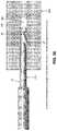
- inserter 15generally comprises a shaft 195 , a handle 200 and a pushrod 205 .
- Shaft 195generally comprises a hollow tube having a distal end 210 , a proximal end 215 and a lumen 220 extending therebetween.
- Distal end 210 of shaft 195terminates in a sharp point 225 .
- a slot 227is formed in distal end 210 of shaft 195 and may terminate in a shoulder 228 .
- slot 227extends proximally along shaft 195 so that it is coextensive with a slot 229 formed in inserter 15 ( FIG. 26 ), whereby to allow suture 30 to separate from inserter 15 after distal anchor 20 and proximal anchor 25 have been set.
- Lumen 220is sized to slidably receive distal anchor 20 ( FIG. 28 ) and proximal anchor 25 (as will hereinafter be discussed).
- a mount 230is secured to proximal end 215 of shaft 195 .
- Handle 200comprises a distal end 235 , a proximal end 240 , and a bore 245 extending therebetween.
- a first counterbore 250is formed at the distal end of handle 200
- a second counterbore 255is formed just proximal to first counterbore 250 , with first counterbore 250 being sized to receive shaft 195 and second counterbore 255 being sized to receive mount 230 , whereby to secure shaft 195 to handle 200 .
- a third counterbore 260is formed at the proximal end of handle 200 .
- a groove 265is formed on the top side of handle 200 for receiving proximal anchor 25 ( FIG. 27 ).
- Groove 265communicates with bore 245 via a passageway 270 , whereby to allow proximal anchor 25 to be advanced into bore 245 , as will hereinafter be discussed.
- Another groove 275is formed on the top side of handle 200 for slidably receiving a suture sled 280 .
- Suture sled 280is biased proximally by a spring 285 .
- Suture sled 280includes a pair of suture cleats 290 for releasably securing loop 320 of suture 30 to suture sled 280 , as will hereinafter be discussed.
- Pushrod 205comprises a pusher 295 which is sized to be slidably received within bore 245 of handle 200 and lumen 220 of shaft 195 .
- Pusher 295comprises a distal end 300 ( FIG. 28 ) and a proximal end 305 ( FIG. 27 ).
- Distal end 300 of pusher 295is preferably rounded so as to facilitate turning of distal anchor 20 and/or proximal anchor 25 when they are advanced out of shaft 195 of inserter 15 , as will hereinafter be discussed.
- a thumb button 310is secured to proximal end 305 of pusher 295 , whereby to allow pusher 295 to be advanced distally by pressing on thumb button 310 .
- thumb button 310may be used to retract pusher 295 , e.g., by gripping thumb button 310 between the thumb and forefinger of the user and pulling proximally, whereby to retract pusher 295 proximally.
- a removable stop 315FIG. 27A ) may be fitted about thumb button 310 , proximal to handle 200 , so as to prevent distal movement of thumb button 310 and hence prevent distal movement of pusher 295 .
- anchor assembly 10Prior to use, anchor assembly 10 is mounted to inserter 15 . More particularly, distal anchor 20 is loaded into distal end 210 of shaft 195 so that suture 30 extends out slot 227 of shaft 195 ( FIG. 28 ). Proximal anchor 25 is loaded into groove 265 of handle 200 , suture 30 is drawn taut by pulling on loop 320 , and then loop 320 of suture 30 is secured to suture cleats 290 . Note that loop 320 is the portion of suture 30 which extends between where the suture exits vertical bore 135 of proximal anchor 25 and re-enters vertical bore 130 of proximal anchor 25 .
- Pushrod 205is inserted into bore 245 of handle 200 and lumen 220 of shaft 195 until removable stop 315 engages the proximal end of handle 200 . At this point, distal end 300 of pusher 295 abuts distal anchor 20 ( FIG. 28 ).
- suture assembly 10is mounted to inserter 15 at the time of manufacture and prior to packaging and sterilization, although suture assembly 10 may also be mounted to inserter 15 at the time of use if desired.
- distal anchor 20is intended to be positioned on one side of a fissure
- proximal anchor 25is intended to be positioned on another side of the fissure
- suture 30is thereafter tensioned so as to close the fissure, whereby to treat degenerative disc disease.
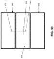
- distal anchor 20may be passed through the annulus of an intervertebral disc 325 at a location 330 on one side of a fissure 335
- proximal anchor 25may be passed through the annulus of the same intervertebral disc 325 at a location 340 on the opposite side of a fissure 335 , so that the suture 30 spans fissure 335 and holds it closed.
- distal anchor 20may be inserted into a vertebral body 345 adjacent to an intervertebral disc 325 having a fissure 335 , and proximal anchor 25 may be passed through the annulus of that intervertebral disc 325 at a location 340 on the opposite side of a fissure 335 , so that the suture 30 spans fissure 335 and holds it closed.
- a holemay be pre-formed in the vertebral body (e.g., by drilling, tapping, punching, etc.).
- annulus reconstructionwill now be discussed in the context of positioning distal anchor 20 in a vertebral body and proximal anchor 25 in the intervertebral disc.
- a hole 350is formed (e.g., by drilling, tapping, punching, etc.) in a vertebral body 345 ( FIG. 34 ), the distal end of shaft 195 is inserted into hole 350 to an appropriate depth ( FIG. 35 ), and then removable stop 315 ( FIG. 29 ) is removed from thumb button 310 . Then thumb button 310 is advanced toward handle 200 , causing the distal end of pusher 295 to advance distal anchor 20 out of shaft 195 ( FIG. 36 ).
- suture sled 280moves distally along handle 200 , against the power of spring 285 , thereby allowing suture 30 (and hence ball 185 set at the distal end of suture 30 ) to also move distally with distal anchor 20 .
- thumb button 310continues to advance distally toward handle 200 , suture sled 280 reaches the end of its stroke in groove 275 , thereby preventing further distal movement of suture 30 (and hence preventing further distal movement of ball 185 set at the distal end of suture 30 ). See FIG. 37 .
- distal anchor 20pivots on ball 185 as distal inclined surface 60 of distal anchor 20 rides upward on ball 185 , thereby causing distal anchor 20 to rotate within the bone ( FIG. 38 ).
- the camming engagement of inclined distal surface 60 of distal anchor 20 with ball 185causes distal anchor 20 to turn within vertebral body 345 .
- the “throw” of suture sled 280effectively sets the depth of distal anchor 20 , since it effectively sets the position of ball 185 within the vertebral body 345 .
- Inserter 15is then moved proximally so as to apply a proximal force to distal anchor 20 via suture 30 , whereby to set distal anchor 20 into vertebral body 345 .
- the pointed heel 87 formed by inclined proximal surface 65 and proximal notch 85is set into the vertebral body, whereby to facilitate setting of distal anchor 20 as suture 30 is pulled proximally. This completes setting of distal anchor 20 .
- the provision of the novel apparatus of the present inventionprovides a significant advantage over conventional toggle anchors of the prior art, since the present invention permits the toggle-type distal anchor 20 to be reliably toggled and set in dense tissue such as an intervertebral body and/or an intervertebral disc.
- conventional toggle-type anchorshave had limited success when set within the interior of tissue in general, and particularly when set within the interior of dense tissue such as an intervertebral body and/or an intervertebral disc, since they provide inconsistent toggling and low pull-out strengths.
- distal anchor 20By contrast, with the present invention, the unique camming engagement of inclined distal surface 60 of distal anchor 20 with the restrained ball 85 causes distal anchor 20 to turn even when it is within the interior of dense tissue such as an intervertebral body and/or an intervertebral disc. Furthermore, the pointed heel 87 of distal anchor 20 facilitates setting of the anchor when suture 30 is tensioned.
- loop 320 of suture 30is released from suture cleats 290 , pushrod 205 is removed from shaft 195 and handle 200 , and inserter 15 is withdrawn from the bone (if it has not already been withdrawn from the bone).
- proximal anchor 25is drawn distally through passageway 270 and into bore 245 in handle 200 (due to the fact that proximal anchor 25 encounters some impedance to sliding along suture 30 since suture 30 follows a serpentine path through proximal anchor 25 , and due to the fact that inserter 15 is being withdrawn proximally).
- removable stop 315is replaced on thumb button 310 , and pushrod 205 is advanced into bore 245 of handle 200 and into lumen 220 of shaft 195 .
- This actionadvances proximal anchor 25 along lumen 220 of shaft 195 .
- Pushrod 205is advanced until removable stop 315 engages the proximal end of handle 200 .
- proximal anchor 25is disposed in the distal end of shaft 195 , but is prevented from being ejected out of the distal end of shaft 195 due to the engagement of removable stop 315 with the proximal end of handle 200 .
- shaft 195 of inserter 15is inserted through the annulus on the far side of the fissure, so that suture 30 spans the fissure. See FIG. 38A .
- removable stop 315is removed from thumb button 310 , and thumb button 310 is advanced distally so as to cause pusher 295 to eject proximal anchor 25 out of shaft 195 and into the nucleus of the intervertebral disc.
- the geometry of proximal anchor 25 and the tension on suture 30causes proximal anchor 25 to begin turning within the nucleus of the intervertebral disc. See FIG. 38B .
- shaft 195 of inserter 15is removed from the annulus, and then loop 320 of suture 30 is pulled proximally, causing suture 30 to be pulled taut, whereby to cause proximal anchor 25 to turn further within the nucleus.
- horizontal slot 165includes a narrower inner portion 175
- pulling proximally on loop 320 of suture 30also causes suture 30 to be drawn into narrower inner portion 175 of bottom horizontal slot 165 .
- This actioncan introduce additional impedance into the system, and this combined impedance (i.e., the combined impedance provided by (i) the serpentine path of suture 30 through proximal anchor 25 , and (ii) the light hold imposed on the suture by narrower inner portion 175 of bottom horizontal slot 165 ) is sufficient to temporarily hold suture 30 to proximal anchor 25 .
- this combined impedancei.e., the combined impedance provided by (i) the serpentine path of suture 30 through proximal anchor 25 , and (ii) the light hold imposed on the suture by narrower inner portion 175 of bottom horizontal slot 165 .
- proximal end 190 of suture 30is pulled so as to draw loop 320 of suture 30 down into the nucleus of the intervertebral disc. See FIG. 38F . Pulling continues until the half-hitch configuration of loop 320 and proximal end 190 of suture 30 are drawn into top horizontal slot 145 of proximal anchor 25 , i.e., so that the aforementioned half-hitch is disposed in top horizontal slot 145 of proximal anchor 25 , whereby to prevent the half-hitch from slipping through itself and hence securing suture 30 to proximal anchor 25 .
- suture 30is also pulled into bottom horizontal slot 150 and, where bottom horizontal slot 150 includes narrower inner portion 160 , into the narrower inner portion 160 of bottom horizontal slot 150 , whereby to further hold suture 30 to proximal anchor 25 . See FIG. 38G .
- the proximal end 190 of suture 30may then be trimmed away, whereby to complete the repair.
- proximal anchor 25provides a significant advantage over the conventional toggle anchors of the prior art, since it provides novel means for knotlessly securing suture 30 to proximal anchor 25 , whereby to allow the tension of suture 30 to be reliably set between distal anchor 20 and proximal anchor 25 .
- the novel construction provided by proximal anchor 25provides a unique solution to the problem of knotlessly securing suture to an anchor. More particularly, the knotless securement mechanism of proximal anchor 25 avoids the deficiencies of prior art toggle anchor systems using cinch knots (see Cauthen III et al. as discussed above) and/or filament enlargements/anchor narrowings (see Cauthen III et al. as discussed above).
- proximal anchor 25provides a significant improvement over the prior art serpentine suture securement mechanisms sometimes found in prior art bone anchors. More particularly, various prior art bone anchors (e.g., screw-type bone anchors) have previously attempted to use serpentine passageways through the bone anchor to knotlessly secure a suture to the bone anchor. However, such prior art serpentine suture securement mechanisms have traditionally required the designer to choose between low holding strength (but relative ease in pulling the suture through the serpentine passageways) or high holding strength (and significant difficulty in pulling the suture through the serpentine passageways).
- prior art serpentine suture securement mechanismshave traditionally required the designer to choose between low holding strength (but relative ease in pulling the suture through the serpentine passageways) or high holding strength (and significant difficulty in pulling the suture through the serpentine passageways).
- the present inventionavoids this problem, providing both high holding strength and relative ease of pulling the suture through the serpentine passageways, by (i) allowing the suture to be accessed at a midpoint within the anchor's serpentine pathway (e.g., by pulling on loop 320 ), and (ii) providing additional holding means to supplement the holding power of the serpentine suture pathway (i.e., the aforementioned half-hitch and, to a significantly lesser extent, the friction fit of suture 30 within narrower inner portion 175 of bottom horizontal slot 165 and narrower inner portion 160 of bottom horizontal slot 150 (to the extent that bottom horizontal slot 165 comprises a narrower inner portion 175 and bottom horizontal slot 150 comprises a narrower inner portion 160 ).
- the distal anchor 20is set into tissue on one side of the fissure, the proximal anchor is deployed into tissue on the other side of the fissure, and then the suture is appropriately tensioned and made fast to the proximal anchor, whereby to effect the repair with the degree of tension selected by the user.
- the distal anchorcan be reliably turned and set within the interior of relatively dense tissue such as bone (as well as within the interior of other tissue) due to its unique construction and deployment mechanism.
- the proximal anchoris capable of providing high holding strengths, e.g., on the order of 16 pounds of holding strength.
- proximal anchor 25is held to suture 30 to a large extent by the impedance provided by the half-hitch construct (which is aided against slipping by virtue of its disposition in top horizontal slot 145 ), and to a lesser extent by the serpentine suture path through proximal anchor 25 , and to a much smaller extent by the light hold imposed on suture 30 by narrower inner portion 175 of bottom horizontal slot 165 and narrower inner portion 155 of bottom horizontal slot 150 (to the extent that bottom horizontal slot 165 comprises a narrower inner portion 175 and bottom horizontal slot 150 comprises a narrower inner portion 160 ).
- bottom horizontal slot 165comprises a narrower inner portion 175
- the hold imposed on suture 30 by narrower inner portion 175 of bottom horizontal slot 165may be relatively nominal, inasmuch as it provides a useful impedance on suture 30 only during the brief period of time that loop 320 is being reduced and the aforementioned half-hitch is being formed—after loop 320 has been reduced and the aforementioned half-hitch has been set, the significant holding power on suture 30 is provided by the half-hitch construct and the serpentine suture path extending through proximal anchor 25 .
- bottom horizontal slot 165comprises a narrower inner portion 175
- narrower inner portion 175is providing a useful impedance on suture 30
- the patientis lying stationary on the operating table and only a nominal load is imposed on the suture—unlike when the patient is upright and moving about, when a substantial load is imposed on the suture.
- bottom horizontal slot 165comprises a narrower inner portion 175 and bottom horizontal slot 150 comprises a narrower inner portion 160
- the serpentine suture path through proximal anchor 25plus the light impedance imposed on suture 30 by narrower inner portion 175 of bottom horizontal slot 165 and narrower inner portion 155 of bottom horizontal slot 150 , collectively provide about 4-6 pounds of holding strength, and the half-hitch construct of proximal end 190 of suture 30 passing through loop 320 , with the half-hitch construct being drawn into top horizontal slot 145 of proximal anchor 25 , brings the total holding strength to about 16 pounds of holding strength.
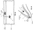
- a suture retriever 380having a loop 385 at its distal end, is advanced through a lumen 390 of tensioner 375 ( FIG. 39 ).
- the proximal end of suture 30is fed through loop 385 , which is then pulled proximally through the tensioner so as to draw suture 30 through the tensioner ( FIG. 40 ).
- the feet 395 of tensioner 375are then placed against the annulus adjacent to where suture 30 exits the annulus, and suture 30 is then pulled proximally, whereby to tension the suture and set it in position. As this occurs, feet 395 of tensioner 375 prevent the annulus from bowing outward, which could enable proximal anchor 25 to pass through the annulus.
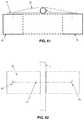
- Tensioner 400generally comprises a shaft 405 having a distal end 410 and a proximal end 415 .
- Distal end 410terminates in a foot 420 .
- a ramped suture pathway 425extends through distal end 410 of shaft 405 and through foot 420 .
- Proximal end 415 of shaft 405is mounted to a handle 430 .
- a cutter tube 435is slidably mounted on shaft 405 .
- Cutter tube 435has a sharpened distal rim 440 .
- suture 30when suture 30 is to be tensioned, the proximal end 190 of suture 30 is fed through ramped suture pathway 425 , foot 420 is placed against the annulus adjacent to where suture 30 exits the annulus, and then suture 30 is tensioned, with foot 420 of the tensioner preventing the annulus from bowing outward. Thereafter, excess suture may be cut away by moving cutter tube 435 distally along shaft 405 until its sharpened distal rim 440 engages and trims away excess suture.
- system 5is discussed in the context of closing a fissure in the annulus of an intervertebral disc. However, it should be appreciated that system 5 may also be used to effect other anatomical repairs and/or fixations.
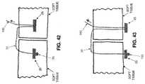
- the present inventionmay be used to hold two pieces of soft tissue in apposition to one another to effect a repair (e.g., so as to close an incision in the skin). See, for example, FIG. 42 , where distal anchor 20 is shown disposed within the interior of one piece of soft tissue and proximal anchor 25 is shown disposed within the interior of another piece of soft tissue; and FIG. 43 , where distal anchor 20 is shown disposed against an outer surface of one piece of soft tissue and proximal anchor 25 is shown disposed against an outer surface of another piece of soft tissue.
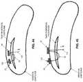
- the present inventionmay be used to hold two pieces of cartilage in apposition to one another to effect a repair (e.g., so as to close a tear in meniscal cartilage). See, for example, FIG. 44 , where distal anchor 20 is shown disposed within the interior of one section of meniscal cartilage and proximal anchor 25 is shown disposed within the interior of another section of the same meniscal cartilage; and FIGS. 45 and 46 , where distal anchor 20 is shown disposed against an outer surface of one section of meniscal cartilage and proximal anchor 25 is shown disposed against an outer surface of another section of the same meniscal cartilage.
- the present inventionmay be used to hold two pieces of bone in apposition to one another so as to effect a repair (e.g., so as to fuse together bone). See FIG. 47 .
- the present inventionmay be used to hold a piece of soft tissue in apposition to bone to effect a repair (e.g., so as to attach soft tissue to bone). See, for example, FIG. 48 .
- the present inventionmay be used to hold a piece of cartilage in apposition to bone to effect a repair (e.g., so as to attach labrum to bone or to attach meniscal cartilage to bone). See FIG. 49 .
- the present inventionmay be used to hold a prosthesis in apposition to soft tissue or bone, or to hold soft tissue or bone in apposition to a prosthesis, and/or to hold any first object in apposition to any second object.
- distal anchor 20 and suture 30it is also possible to use just distal anchor 20 and suture 30 to effect anatomical repairs and/or fixations, with proximal anchor 25 being omitted altogether. See, for example, FIG. 50 , where a knot is used to hold soft tissue to a bone receiving distal anchor 20 , and FIG. 51 , where a knot is used to hold a labrum to an acetabular rim receiving distal anchor 20 .
- multiple suture strandsmay be attached to the large ball (or knot) 185 which is positioned distal to distal anchor 20 , which can facilitate repair and/or fixation procedures.
- proximal anchor 25 and suture 30may be used with an anchor other than distal anchor 20 to effect anatomical repairs and/or fixations.
- proximal anchor 25 and suture 30may be used in conjunction with a conventional bone anchor (e.g., a conventional screw-type bone anchor or by a conventional barb-type bone anchor), with the conventional bone anchor replacing the aforementioned distal anchor 20 of the present invention.
- novel system 5may be used to close a fissure in the annulus of an intervertebral disc, and/or to effect other anatomical repairs and/or other anatomical fixations.
- novel system 5may be used in a novel approach to anchor sensory nerve stimulator (SNS) leads. More particularly, in sensory nerve stimulation therapy, electrical leads are positioned adjacent to nerves and used to deliver electrical stimulation to those nerves so as to provide pain relief to a patient. In one significant application of nerve stimulation therapy, sensory nerve stimulator (SNS) leads are disposed adjacent to nerves in the spinal column, whereby to deliver electrical stimulation to those nerves and provide pain relief to the patient. See, for example, FIG. 52 , which shows an SNS lead disposed adjacent to a nerve in the spinal column.
- Novel system 5provides a new and improved approach for stabilizing an SNS lead adjacent to a nerve in the spinal column, by anchoring the SNS lead to one mass of material using the distal anchor of system 5 and by anchoring the SNS lead to another mass of material using the proximal anchor of system 5 , with the intervening suture securing the SNS lead reliably in position.
- novel system 5comprises a distal anchor 20 which is deployable, using a minimally-invasive approach, against the exterior of a hard or soft object (e.g., a bone, soft tissue, a hard prosthesis, a soft prosthesis, etc.), or within the interior of a hard or soft object (e.g., a bone, soft tissue, a hard prosthesis, a soft prosthesis, etc.), thereby providing a wide range of objects to which the distal anchor may be secured.
- a hard or soft objecte.g., a bone, soft tissue, a hard prosthesis, a soft prosthesis, etc.
- Novel system 5also comprises a proximal anchor 25 which is deployable, using a minimally-invasive approach, against the exterior of a hard or soft object (e.g., a bone, soft tissue, a hard prosthesis, a soft prosthesis, etc.), or within the interior of a soft object (e.g., soft tissue, a soft prosthesis, etc.), thereby providing a wide range of objects to which the distal anchor may be secured.
- novel system 5comprises a connecting suture 30 which may be used to atraumatically, but reliably, secure an SNS lead in position.
- the term “bone”is intended to include any bone or bone-like structure including, but not limited to, a vertebral body, a pedicle, a transverse process, a facet structure, a lamina, a spinous process, etc.
- the term “soft tissue”is intended to include any relatively “soft” structure including, but not limited to, an intervertebral disc, a muscle, a ligament, a tendon, etc.
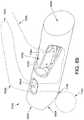
- FIG. 53shows an SNS lead L adjacent to one mass of material M 1 for receiving distal anchor 20 of system 5 , and adjacent to another mass of material M 2 for anchoring proximal anchor 25 of system 5 .
- FIG. 54shows distal anchor 20 deployed against the exterior of a hard or soft mass of material M 1 (e.g., a bone, soft tissue, a hard prosthesis, a soft prosthesis, etc).
- FIG. 55shows distal anchor 20 deployed within the interior of a hard or soft mass of material M 1 (e.g., a bone, soft tissue, a hard prosthesis, a soft prosthesis, etc.).
- FIG. 53shows an SNS lead L adjacent to one mass of material M 1 for receiving distal anchor 20 of system 5 , and adjacent to another mass of material M 2 for anchoring proximal anchor 25 of system 5 .
- FIG. 54shows distal anchor 20 deployed against the exterior of a hard or soft mass of material M 1 (e.g., a bone, soft tissue, a hard prosthesis,
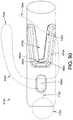
- FIG. 56shows proximal anchor 25 deployed against the exterior of a hard or soft mass of material M 2 (e.g., a bone, soft tissue, a hard prosthesis, a soft prosthesis, etc).
- FIG. 57shows proximal anchor 25 deployed within the interior of a soft mass of material M 2 (e.g., soft tissue, a soft prosthesis, etc.).
- distal anchor 20may be deployed through, or deployed within, any appropriate anatomical or prosthetic structure
- proximal anchor 25may be deployed through, or deployed within, any appropriate anatomical or prosthetic structure, whereby to enable suture 30 to secure SNS lead L in the desired position within the patient's anatomy.
- suture 30may simply extend over SNS lead L, holding the SNS lead against underlying tissue.
- suture 30may be wrapped around SNS lead L. Where suture 30 is wrapped around the SNS lead, it may be possible to support the SNS lead in position even in the absence of underlying tissue, since suture 30 can be used to suspend SNS lead L over a gap in the tissue.
- SNS lead Lmay include an associated mount, e.g., in the form of a web W extending laterally about the SNS lead, and distal anchor 20 and proximal anchor 25 may be advanced through web W prior to deployment through or into a mass of material (e.g., M 1 or M 2 ), in the manner shown in FIGS. 61 and 62 .
- a mass of materiale.g., M 1 or M 2
- FIGS. 63-70show a variety of ways in which system 5 may be used to secure SNS lead L to adjacent structures.
- novel system 5may be used to close a fissure in the annulus of an intervertebral disc, and/or to effect other anatomical repairs and/or other anatomical fixations, including anchoring sensory nerve stimulator (SNS) leads.
- SNSanchoring sensory nerve stimulator
- novel system 5utilizes the aforementioned distal anchor 20 and the aforementioned suture 30 (and also the aforementioned inserter 15 ), but substitutes an alternative proximal anchor 25 A ( FIGS. 71 and 72 ) for the aforementioned proximal anchor 25 .
- proximal anchor 25 Acomprises a generally cylindrical body 90 A having a distal end 95 A, a proximal end 100 A and a generally circular side wall 105 A. Distal end 95 A terminates in a distal surface 110 A. Proximal end 100 A terminates in a proximal surface 120 A.
- a vertical bore 126 Apasses completely through proximal anchor 25 A. Vertical bore 126 A is sized to slidably receive suture 30 therein.
- a recess 131 Apasses part way through proximal anchor 25 A.
- a U-shaped slot 136 Apasses part way through proximal anchor 25 A. Recess 131 A and U-shaped slot 136 A together define a flexible finger 141 A.
- a gap 142 Ais formed between the inner tip 143 A of flexible finger 141 A and the edge 144 A formed at the convergence of recess 131 A and U-shaped slot 136 A.
- gap 142 Ais sized so as to be approximately 50% of the width of suture 30 when flexible finger 141 A is in its relaxed, unbiased condition (i.e., in the position shown in FIGS. 71 and 72 ) and when suture 30 is in its normal, uncompressed condition.
- a bottom horizontal slot 151 Aextends between vertical bore 126 A and recess 131 A. Bottom horizontal slot 151 A may be stepped, comprising a wider outer portion 156 A and a narrower inner portion 161 A.
- wider outer portion 156 Amay be sized to slidably receive suture 30 therein so as to help keep proximal anchor 25 A and suture 30 from binding when they are disposed within the aforementioned inserter 15 , but narrower portion 161 A may be sized to snugly receive suture 30 therein whereby to provide a light hold on suture 30 when suture 30 is disposed therein.
- suture 30is passed through proximal anchor 25 A so that suture 30 extends down vertical bore 126 A, through wider outer portion 156 A of bottom horizontal slot 151 A, up through recess 131 A and out U-shaped slot 136 A.
- suture 30has a diameter which is approximately twice the size of gap 142 A formed between inner tip 143 A of flexible finger 141 A and edge 144 A of proximal anchor 25 A, flexible finger 141 A will normally bear against the suture disposed in gap 142 A.
- suture 30follows a non-linear path through proximal anchor 25 A, and this non-linear path creates impedance to the passage of suture 30 through proximal anchor 25 A.
- proximal anchor 25 Ais also deployed at the surgical site (again, preferably using the aforementioned inserter 15 ), and then suture 30 is set by pulling proximally on suture 30 .
- suture 30is pulled proximally, flexible finger 141 A flexes away from the body of proximal anchor 25 A, thereby allowing suture 30 to slide through recess 131 A and U-shaped slot 136 A (as well as through vertical bore 126 A and wider outer portion 156 A of bottom horizontal slot 151 A).
- bottom horizontal slot 151 Acomprises a narrower portion 161 A
- suture 30is pulled from wider outer portion 156 A of bottom horizontal slot 151 A into narrower portion 161 A of bottom horizontal slot 151 A so that suture 30 is snugly received therein, such that proximal anchor 25 A provides a light hold on suture 30 .
- a single anchor system 500may be used to secure an object (e.g., a sensory nerve stimulator “SNS” lead 505 ) to tissue (e.g., fascia 510 ).
- objecte.g., a sensory nerve stimulator “SNS” lead 505
- tissuee.g., fascia 510
- single anchor system 500comprises a novel anchor 515 and a suture 520 .
- Single anchor system 500is preferably deployed using the aforementioned inserter 15 (or another appropriate inserter).
- anchor 515comprises a generally cylindrical body 535 having a distal end 540 , a proximal end 545 and a generally circular side wall 550 .
- Distal end 540terminates in a flat or somewhat inclined distal end surface 555 and a more inclined distal end surface 560 .
- Flat or somewhat inclined distal end surface 555is sufficiently large so as to render distal end 540 of anchor 515 substantially blunt (but, where distal end surface 555 is somewhat inclined, also having a tapered lead-in).
- Inclined distal end surface 560is pitched at an appropriate angle (e.g., 30 degrees, 45 degrees, etc.) so as to cause anchor 515 to turn during deployment (in the same manner that the aforementioned distal anchor 20 comprises a corresponding inclined distal surface 60 for causing turning), as will hereinafter be discussed.
- Proximal end 545terminates in an inclined proximal end surface 565 .
- a vertical bore 570passes through anchor 515 .
- Vertical bore 570is sized to slidably receive suture 520 therein.
- a horizontal slot 575extends between inclined distal end surface 560 and vertical bore 570 .
- Horizontal slot 575is preferably also sized to slidably receive suture 520 therein, and helps keep anchor 515 and suture 520 from binding when they are disposed within the aforementioned inserter 15 .
- a pair of vertical bores 581 , 583are also disposed in anchor 515 , proximal to vertical bore 570 .
- Vertical bores 581 , 583are also sized to slidably receive suture 520 therein.
- a bottom horizontal slot 586extends between vertical bore 581 and vertical bore 583 .
- suture 520follows a non-linear path through anchor 515 , and this non-linear path creates impedance to the passage of suture 520 through anchor 515 .
- bottom horizontal slot 586may be stepped, comprising a wider outer portion 587 and a narrower inner portion 588 .
- Wider outer portion 587may be sized to slidably receive suture 520 therein so as to help keep anchor 515 and suture 520 from binding when they are disposed within the aforementioned inserter 15
- narrower portion 588may be sized to snugly receive suture 520 therein, whereby to provide a light hold on suture 520 when suture 520 is disposed therein.
- suture 520has a distal end 591 terminating in a large ball (or knot) 592 , and a proximal segment 593 .
- Suture 520is passed through anchor 515 so that so that large ball (or knot) 592 is disposed against the more inclined distal end surface 560 , and the suture extends along horizontal slot 575 of anchor 515 , up vertical bore 570 of anchor 515 , around the object (e.g., a sensory nerve stimulator “SNS” lead 505 ) which is to be secured to tissue (e.g., fascia 510 ), down vertical bore 581 , through bottom horizontal slot 586 (i.e., through wider outer portion 587 of bottom horizontal slot 586 where bottom horizontal slot is stepped), and up vertical bore 583 .
- tissuee.g., fascia 510
- anchor 515is deployed at the surgical site with suture 520 under tension so that anchor 515 is turned as it is ejected from the aforementioned inserter 15 (in the same manner that the aforementioned distal anchor 20 is turned as it is ejected from the aforementioned inserter 15 ), then suture 520 is tensioned by pulling proximally on proximal end 593 of suture 520 .
- sensory nerve stimulator “SNS” lead 505is secured against fascia 510 (i.e., by virtue of anchor 515 being set in fascia 510 and by virtue of lead 505 being captured to anchor 515 via suture 520 ).
- suture 520will be held against slippage relative to anchor 515 by virtue of the fact that suture 520 follows a non-linear path through anchor 515 , and this non-linear path creates impedance to the passage of suture 520 through anchor 515 .
- suture 520is thereafter tensioned further, and where bottom horizontal slot 586 comprises a narrower portion 588 , suture 520 will be pulled from wider outer portion 587 of bottom horizontal slot 586 into narrower portion 588 of bottom horizontal slot 586 so that suture 520 is snugly received therein. This can provide an additional hold on suture 520 .
- a half-hitch 594is formed in suture 520 on the proximal side of anchor 520 so as to secure the fixation.
- half hitch 594will provide the primary fixation of suture 520 to anchor 515 , and the impedance created by the non-linear path of suture 520 through anchor 515 will provide significant additional fixation of suture 520 .
- bottom horizontal slot 586comprises a narrower portion 588
- movement of suture 520 into narrower portion 588can also provide a small additional holding force.
- a single anchor system 600may be used (e.g., with the aforementioned inserter 15 ) to secure an object (e.g., a sensory nerve stimulator SNS lead 605 ) to tissue (e.g., fascia 610 ).
- objecte.g., a sensory nerve stimulator SNS lead 605
- tissuee.g., fascia 610
- single anchor system 600comprises a novel anchor 615 and a suture 620 .
- Single anchor system 600is preferably deployed using the aforementioned inserter 15 (or another appropriate inserter).
- anchor 615comprises a generally cylindrical body 625 having a distal end 630 , a proximal end 635 and a generally circular side wall 640 .
- Distal end 630terminates in a flat or somewhat inclined distal end surface 645 and a more inclined distal end surface 650 .
- Flat or somewhat inclined distal end surface 645is sufficiently large so as to render distal end 630 of anchor 615 substantially blunt (but, where distal end surface 645 is somewhat inclined, also having a tapered lead-in).
- Inclined distal end surface 650is pitched at an appropriate angle (e.g., 30 degrees, 45 degrees, etc.) so as to cause anchor 615 to turn during deployment (in the same manner that the aforementioned distal anchor 20 comprises a corresponding inclined distal surface 60 for causing turning), as will hereinafter be discussed.
- Proximal end 635terminates in an inclined proximal end surface 655 .
- a vertical bore 660passes completely through anchor 615 .
- Vertical bore 660preferably intersects inclined distal end surface 650 and is sized to slidably receive suture 620 therein.
- a recess 665passes part way through anchor 615 .
- a U-shaped slot 670passes part way through anchor 615 .
- Recess 665 and U-shaped slot 670together define a flexible finger 675 .
- a gap 680is formed between the inner tip 685 of flexible finger 675 and the edge 690 formed at the convergence of recess 665 and U-shaped slot 670 .
- gap 680is sized so as to be approximately 50% of the width of suture 620 when flexible finger 675 is in its relaxed, unbiased condition (i.e., in the position shown in FIGS. 78 and 83 ) and when suture 620 is in its normal, uncompressed condition.
- a bottom horizontal slot 695extends between vertical bore 660 and recess 665 . Bottom horizontal slot 695 may be stepped, comprising a wider outer portion 700 and a narrower inner portion 705 .
- wider outer portion 700may be sized to slidably receive suture 620 therein so as to help keep anchor 615 and suture 620 from binding when they are disposed within the aforementioned inserter 15 , but narrower portion 705 may be sized to snugly receive suture 620 therein whereby to provide a light hold on suture 620 when suture 620 is disposed therein.
- bottom horizontal slot 695may comprise a slot of uniform width with a chamfer lead-in.
- suture 620has a distal end 710 terminating in a large ball or knot 715 , a proximal segment 720 , and an intermediate loop 725 which may be releasably secured to suture sled 280 of inserter 15 .
- Suture 620is passed through anchor 615 so that large ball or knot 715 is disposed against the more inclined distal end surface 650 , and the suture extends into vertical bore 660 , loops around to form loop 725 (which is preferably releasably secured to suture sled 280 of inserter 15 ) and extends back down vertical bore 660 , through wider outer portion 700 of bottom horizontal slot 695 (if bottom horizontal slot 695 is stepped), up through recess 665 and out U-shaped slot 670 .
- suture 620has a diameter which is approximately twice the size of gap 680 formed between inner tip 685 of flexible finger 675 and edge 690 of anchor 615 .
- flexible finger 675will normally bear against the suture disposed in gap 680 .
- the presence of the “oversized” suture 620 in the “undersized” gap 680will cause flexible finger 675 to be flexed upwardly (from the angle of view of FIG. 83 ) so as to accommodate suture 620 , with inner tip 685 of flexible finger 675 capturing the suture against edge 690 of anchor 615 .
- some compression of suture 620may occur in this condition.
- suture 620follows a non-linear path through anchor 615 , and this non-linear path creates impedance to the passage of suture 620 through anchor 615 .
- anchor 615is deployed at the surgical site with suture 620 under tension so that anchor 615 is turned as it is ejected from the aforementioned inserter 15 (in the same manner that the aforementioned distal anchor 20 is turned as it is ejected from the aforementioned inserter 15 ).
- thisis accomplished by releasably mounting loop 725 of suture 620 to suture sled 280 of inserter 15 during insertion of anchor 615 . Then loop 725 of suture 620 is released from suture sled 280 , SNS lead 605 is passed through loop 725 , and then suture 620 is tensioned by pulling proximally on proximal end 720 of suture 620 .
- suture 620is pulled from wider outer portion 700 of bottom horizontal slot 695 into narrower portion 705 of bottom horizontal slot 695 so that suture 620 is snugly received therein, such that anchor 615 provides a light hold on suture 620 .
- single anchor system 600is configured so that its failure mode comprises slipping, not breaking (i.e., suture 620 will slip relative to anchor 615 before anchor 615 will break).
- anchor 615comprises carbon fiber-reinforced PEEK (30%).
- anchor 615may comprise a radiopaque material so that anchor 615 is visible under X-ray visualization.
- a radiopaque elementmay be incorporated in the body of anchor 615 .
- a piece of Nitinol wiremay be molded into anchor 615 so that the Nitinol wire extends through flexible finger 675 and into the adjoining body of anchor 615 —in this form of the invention, the Nitinol wire reinforces flexible finger 675 at the same time that it provides a radiopaque element in anchor 615 .
- inserter 15is characterized as having a suture sled 280 which is spring mounted to handle 200 .
- Suture sled 280serves as a movable mount for securing the proximal portion of suture loop 320 (or suture loop 725 ) to handle 200 , such that suture sled 280 can slide along handle 200 as distal anchor 20 (or anchor 615 ) is advanced into a mass of material (e.g., an intervertebral disc, a bone, soft tissue, etc.), and then be stopped relative to handle 200 so that distal anchor 20 (or anchor 615 ) is driven against ball 185 (or ball 715 ), whereby to facilitate turning of distal anchor 20 (or anchor 615 ) within the mass of material.
- a mass of materiale.g., an intervertebral disc, a bone, soft tissue, etc.
- suture sled 280is characterized as being spring mounted to handle 200 so that suture sled 280 initially remains in a proximal position, whereby to hold suture 30 (or suture 620 ) under tension, until distal anchor 20 (or anchor 615 ) is driven distally by push rod 205 of inserter 15 , whereupon suture sled 280 is permitted to move distally, against the power of spring 285 , until distal anchor 20 (or anchor 615 ) is at the proper depth within the mass of material, whereupon distal movement of suture sled 280 is stopped, thereby stopping distal movement of ball 185 (or ball 715 ) and hence setting the depth of distal anchor 20 (or anchor 615 ).
- spring 285may be omitted, and other means may be provided for releasably holding suture sled 280 in a proximal position until distal anchor 20 (or anchor 615 ) is driven distally by push rod 205 .
- suture sled 280may be releasably held in a proximal position by means of a yielding stop finger, a ball-and-detent mechanism, or other releasable holding mechanism of the sort well known in the art.
- inserter 15is characterized as having a push rod 205 which is moved distally by manually pressing on thumb button 310 (e.g., in the manner of manually pressing on the plunger of a syringe), whereby to drive distal anchor 20 (or anchor 615 ) distally.
- distal anchor 20or anchor 615
- an impulse mechanismso that an impulse of drive energy is applied to distal anchor 20 (or anchor 615 ).
- distal anchor 20or anchor 615
- a material having limited strengthe.g., PEEK or PLLA
- distal anchor 20 (or anchor 615 )is to be set in a harder mass of material (e.g., bone)
- inserter 15may be provided with a tension spring 800 which is secured to proximal end 240 of handle 200 and to thumb button 310 of push rod 205 .
- thumb button 310may be pulled proximally, away from handle 200 , so that tension spring 800 is stretched and then, when impulse energy is to be applied to distal anchor 20 (or anchor 615 ) via push rod 205 , thumb button 310 is simply released, so that tension spring 800 applies impulse energy to thumb button 310 and hence causes push rod 205 to apply impulse energy to distal anchor 20 (or anchor 615 ).
- suture anchor 615i.e., up through vertical bore 660 , back down through vertical bore 660 , across bottom horizontal slot 695 , up recess 665 and out U-shaped slot 670 .
- a suture threaderis well known in the field of sutures and medical devices utilizing sutures, and generally comprises a substantially resilient device (e.g., a flexible wire) which can be passed through the narrow opening and then used to draw the suture back through the opening (e.g., by passing the suture through an opening in the suture threader, and then pulling the suture threader, including the suture, back through the narrow opening).
- a substantially resilient devicee.g., a flexible wire
- suture anchorwhich facilitates loading a suture into the suture anchor, and which avoids the need for using a separate suture threader, and which facilitates quick and easy loading of a suture through the tortuous path of the suture anchor.
- Anchor 615 Ais generally similar to the aforementioned anchor 615 discussed above, however, anchor 615 A is configured to facilitate simplified loading of a suture through anchor 615 A, as will hereinafter be discussed.
- Anchor 615 Apreferably comprises a generally cylindrical body 625 A having a distal end 630 A, a proximal end 635 A and a generally circular side wall 640 A.
- Distal end 630 Aterminates in a flat or somewhat inclined distal end surface 645 A and a more inclined distal end surface 650 A.
- Flat or somewhat inclined distal end surface 645 Ais sufficiently large so as to render distal end 630 A of anchor 615 A substantially blunt (but, where distal end surface 645 A is somewhat inclined, flat or somewhat inclined distal end surface 645 A is sufficient to provide anchor 615 A with a tapered lead-in).
- Inclined distal end surface 650 Ais pitched at an appropriate angle (e.g., 30 degrees, 45 degrees, etc.) so as to cause anchor 615 A to turn during deployment (i.e., in the same manner that the aforementioned distal anchor 20 comprises a corresponding inclined distal surface 60 for causing turning), as will hereinafter be discussed.
- Proximal end 635 Apreferably terminates in an inclined proximal end surface 655 A.
- a vertical bore 660 Apasses completely through anchor 615 A.
- Vertical bore 660 Apreferably extends substantially perpendicular to the longitudinal axis of anchor 615 A.
- Vertical bore 660 Apreferably intersects inclined distal end surface 650 A and is sized to slidably receive suture 620 A therein.
- a recess 665 Ais formed on one side of generally cylindrical body 625 A and passes part way through anchor 615 A.
- Recess 665 Apreferably extends substantially perpendicular to the longitudinal axis of anchor 615 A.
- a U-shaped slot 670 Ais formed on the opposite side of generally cylindrical body 625 A (i.e., opposite to recess 665 A) and passes part way through anchor 615 A.
- U-shaped slot 670 Apreferably extends substantially perpendicular to the longitudinal axis of anchor 615 A.
- Recess 665 A and U-shaped slot 670 Atogether define a flexible finger 675 A which preferably extends distally within generally cylindrical body 625 A.
- a gap 680 Ais formed between the inner tip 685 A of flexible finger 675 A and the edge 690 A formed at the convergence of recess 665 A and U-shaped slot 670 A.
- gap 680 Ais sized so as to be approximately 50% of the width of suture 620 A when flexible finger 675 A is in its relaxed, unbiased condition (i.e., in the position shown in FIGS.
- a bottom horizontal slot 695 Apreferably extends between vertical bore 660 A and recess 665 A. Bottom horizontal slot 695 A may be stepped, comprising a wider outer portion 700 A and a narrower inner portion 705 A.
- wider outer portion 700 Amay be sized to slidably receive suture 620 A therein so as to help keep anchor 615 A and suture 620 A from binding when they are disposed within the aforementioned inserter 15 , but narrower portion 705 A may be sized to snugly receive suture 620 A therein whereby to provide a light hold on suture 620 A when suture 620 A is disposed therein.
- bottom horizontal slot 695 Amay comprise a slot of uniform width with a chamfer lead-in.
- a suture loading hole 730 Ais formed near the proximal end of U-shaped slot 670 A in the proximal portion of flexible finger 675 A. More particularly, a portion of flexible finger 675 A is cut away (e.g., so as to form a hemicylindrical cutout) near the proximal end of flexible finger 675 A to form suture loading hole 730 A which passes through U-shaped slot 670 A and into recess 665 A.
- Suture loading hole 730 Ais configured to be wider than gap 680 A (i.e., wider than the gap between inner tip 685 A of flexible finger 675 A and edge 690 A formed at the convergence of recess 665 A and U-shaped slot 670 A) so as to facilitate passage of the free end of suture 620 A therethrough.
- suture loading hole 730 Amay be formed in generally cylindrical body 625 A rather than in flexible finger 675 A (i.e., a hemicylindrical cutout may be formed in generally cylindrical body 625 A rather than in flexible finger 675 A); or suture loading hole 730 A may be formed in both flexible finger 675 A and in generally cylindrical body 625 A rather than in just flexible finger 675 A or in just generally cylindrical body 625 A (i.e., hemicylindrical cutouts may be formed in both flexible finger 675 A and in generally cylindrical body 625 A rather than in just flexible finger 675 A or in just generally cylindrical body 625 A).
- Suture 620 Ais generally the same as the aforementioned suture 620 , however, suture 620 A preferably comprises a stiffened free end for facilitating threading of the free end through vertical bore 660 A and through suture loading hole 730 A, as will hereinafter be discussed in further detail. More particularly, as seen in FIGS. 87-92 , suture 620 A has a distal end 710 A terminating in a large ball or knot 715 A, a proximal segment 720 A, and an intermediate loop 725 A which may be releasably secured to suture sled 280 of inserter 15 .
- Suture 620 Ais passed through anchor 615 A so that large ball or knot 715 A is disposed against the more inclined distal end surface 650 A, and the suture extends into vertical bore 660 A, loops around to form loop 725 A (which is preferably releasably secured to suture sled 280 of inserter 15 ) and extends back down vertical bore 660 A, through wider outer portion 700 A of bottom horizontal slot 695 A (if bottom horizontal slot 695 A is stepped), and up through suture loading hole 730 A.
- suture loading hole 730 Acomprises a diameter slightly larger than the diameter of suture 620 A
- suture loading hole 730 Afacilitates easy passage of suture 620 A through recess 665 A and out U-shaped slot 670 A.
- suture 620 AAfter suture 620 A has been threaded through suture loading hole 730 A, the suture is pulled distally so as to lodge suture 620 A in gap 680 A between inner tip 685 A of flexible finger 675 A and edge 690 A formed at the convergence of recess 665 A and U-shaped slot 670 A. Note that inasmuch as suture 620 A has a diameter which is approximately twice the size of gap 680 A formed between inner tip 685 A of flexible finger 675 A and edge 690 A of anchor 615 A, flexible finger 675 A will normally bear against the suture disposed in gap 680 A.
- suture 620 Afollows a non-linear path through anchor 615 A, and this non-linear path creates impedance to the passage of suture 620 A through anchor 615 A.
- suture 620 Ais preferably formed with a stiffened free end in order to facilitate passage of the free end of the suture through vertical bore 660 A and/or through suture loading hole 730 A
- the stiffened free endmay be omitted, and/or, if desired, a suture threader may be passed through suture loading hole 730 A, used to grasp suture 620 A, and then used to pull suture 620 A through suture loading hole 730 A.
- novel anchor 615 A and suture 620 Atogether form a single anchor system 600 A
- single anchor system 600 Amay be used (e.g., with the aforementioned inserter 15 ) to secure an object (e.g., a sensory nerve stimulator SNS lead 605 ) to tissue (e.g., fascia 610 ) in substantially the same manner that single anchor system 600 (and the aforementioned inserter 15 ) may be used.
- objecte.g., a sensory nerve stimulator SNS lead 605
- tissuee.g., fascia 610
- inserter 15comprises the aforementioned removable stop 315 which is removably mounted to the shaft of thumb button 310 between the proximal end of handle 200 and thumb button 310 .
- removable stop 315is removed from the shaft of thumb button 310 so as to allow thumb button 310 to move distally.
- Stop 735generally comprises a distally-extending member 740 which is mounted to (or formed integral with) thumb button 310 and extends distally therefrom.
- the distal end of member 740 of stop 735contacts proximal end 240 of handle 200 .
- the distal end of member 740comprises a seat 742 disposed between a pair of distally-extending fingers 745 ( FIG. 95 ) for engaging a tab 750 mounted to proximal end 240 of handle 200 ( FIG. 95 ).
- handle 200preferably has a non-circular cross-section, comprising a recessed flat 752 .
- thumb button 310When it is desired to actuate thumb button 310 , thumb button 310 is pulled proximally to release seat 742 from engagement with tab 750 (i.e., by moving seat 742 proximally such that seat 742 no longer contacts tab 750 ), and thumb button 310 is rotated 180 degrees (i.e., along an arc 755 ) so that member 740 is arcuately aligned with recessed flat 752 of handle 200 . See FIG. 96 . As this occurs, distally-extending member 740 of stop 735 no longer contacts proximal end 240 of handle 200 and distally-extending member 740 is able to move distally along one side of handle 200 (i.e., along recessed flat 752 ).
- thumb button 310can be again pulled proximally and then rotated 180 degrees so that seat 742 of distally-extending member 740 is aligned with tab 750 of handle 200 , such that seat 742 will re-engage tab 750 if thumb button 310 should be moved distally.
- Stop 760comprises a tab 765 which is hingedly mounted to thumb button 310 .
- Tab 765comprises a cutout 770 for releasably engaging the shaft of thumb button 310 as tab 765 is swung toward the shaft of thumb button 310 .
- tab 765can be selectively interposed between the head of thumb button 310 and proximal end 240 of handle 200 , whereby to prevent undesired actuation of thumb button 310 .
- thumb button 310When it is desired to actuate thumb button 310 , tab 765 is swung radially away from the shaft of thumb button 310 , cutout 770 disengages from the shaft of thumb button 310 and the body of tab 765 is no longer interposed between proximal end 240 of handle 200 and the head of thumb button 310 , whereby to allow thumb button 310 to be actuated as desired. If it is thereafter desired to lock thumb button 310 against actuation, tab 765 can be swung inwardly such that cutout 770 re-engages the shaft of thumb button 310 and is re-interposed between thumb button 310 and proximal end 240 of handle 200 .
Landscapes
- Health & Medical Sciences (AREA)
- Life Sciences & Earth Sciences (AREA)
- Surgery (AREA)
- Engineering & Computer Science (AREA)
- Biomedical Technology (AREA)
- Veterinary Medicine (AREA)
- Public Health (AREA)
- General Health & Medical Sciences (AREA)
- Heart & Thoracic Surgery (AREA)
- Animal Behavior & Ethology (AREA)
- Nuclear Medicine, Radiotherapy & Molecular Imaging (AREA)
- Medical Informatics (AREA)
- Orthopedic Medicine & Surgery (AREA)
- Molecular Biology (AREA)
- Cardiology (AREA)
- Neurology (AREA)
- Transplantation (AREA)
- Rheumatology (AREA)
- Neurosurgery (AREA)
- Radiology & Medical Imaging (AREA)
- Physical Education & Sports Medicine (AREA)
- Vascular Medicine (AREA)
- Oral & Maxillofacial Surgery (AREA)
- Pathology (AREA)
- Prostheses (AREA)
Abstract
Description
- (i) claims benefit of prior U.S. Provisional Patent Application Ser. No. 61/866,955, filed Aug. 16, 2013 by Suture Concepts Inc. and Peter Sorensen et al. for METHOD AND APPARATUS FOR CLOSING A FISSURE IN THE ANNULUS OF AN INTERVERTEBRAL DISC, AND/OR FOR EFFECTING OTHER ANATOMICAL REPAIRS AND/OR FIXATIONS
- (ii) claims benefit of prior U.S. Provisional Patent Application Ser. No. 61/915,433, filed Dec. 12, 2013 by Suture Concepts Inc. and Peter Sorensen et al. for METHOD AND APPARATUS FOR CLOSING A FISSURE IN THE ANNULUS OF AN INTERVERTEBRAL DISC, AND/OR FOR EFFECTING OTHER ANATOMICAL REPAIRS AND/OR FIXATIONS
- (iii) claims benefit of prior U.S. Provisional Patent Application Ser. No. 61/984,431, filed Apr. 25, 2014 by Suture Concepts Inc. and Peter Sorensen et al. for METHOD AND APPARATUS FOR CLOSING A FISSURE IN THE ANNULUS OF AN INTERVERTEBRAL DISC, AND/OR FOR EFFECTING OTHER ANATOMICAL REPAIRS AND/OR FIXATIONS and
- (iv) is a continuation-in-part of prior U.S. patent application Ser. No. 14/068,406, filed Oct. 31, 2013 by Suture Concepts Inc. and Bret A. Ferree for METHOD AND APPARATUS FOR CLOSING FISSURES IN THE ANNULUS FIBROSUS, which in turn claims benefit of:
- (a) prior U.S. Provisional Patent Application Ser. No. 61/720,593, filed Oct. 31, 2012 by Bret A. Ferree for METHOD AND APPARATUS FOR CLOSING FISSURES IN THE ANNULUS FIBROSUS; and
- a distal anchor comprising a generally cylindrical body, a distal end and a proximal end, wherein said distal end comprises an inclined distal end surface, and a vertical bore extending through said generally cylindrical body, perpendicular to the longitudinal axis of said generally cylindrical body;
- a proximal anchor comprising a generally cylindrical body, a distal end and a proximal end, a top surface and a bottom surface, a first vertical bore extending through said generally cylindrical body from said top surface to said bottom surface, perpendicular to the longitudinal axis of the generally cylindrical body, a second vertical bore spaced distally from said first vertical bore and extending from said top surface to said bottom surface parallel to said first vertical bore, a third vertical bore spaced distally from said second vertical bore and extending from said top surface to said bottom surface parallel to said first vertical bore, and a fourth vertical bore spaced distally from said third vertical bore and extending from said top surface to said bottom surface parallel to said first vertical bore; and
- a suture having a proximal end and a distal end, with an enlargement formed at said distal end, wherein said suture extends through said vertical bore of said distal anchor, through said fourth vertical bore of said proximal anchor, through said third vertical bore of said proximal anchor, through said second vertical bore of said proximal anchor and through said first vertical bore of said proximal anchor;
- an anchor comprising a generally cylindrical body, a distal end and a proximal end, wherein said distal end comprises an inclined distal end surface, and a vertical bore extending through said generally cylindrical body, perpendicular to the longitudinal axis of said generally cylindrical body; and
- a suture having a proximal end and a distal end, with an enlargement formed at said distal end, wherein said suture extends through said vertical bore of said anchor;
- an anchor comprising a generally cylindrical body, a distal end and a proximal end, a vertical bore extending through said generally cylindrical body, perpendicular to the longitudinal axis of said generally cylindrical body, a recess formed on one side of said generally cylindrical body and a U-shaped slot formed on the opposing side of said generally cylindrical body whereby to form a flexible finger extending distally within said generally cylindrical body, and further wherein said distal end of said finger is spaced from an opposing portion of said generally cylindrical body; and
- a suture extending through said vertical bore, said recess and said U-shaped slot;
- an anchor comprising a body having a distal end and a proximal end, and a vertical bore extending through said body substantially perpendicular to the longitudinal axis of said body;
- wherein said anchor further comprises a recess formed on one side of said body and a U-shaped slot formed on the opposing side of said body, whereby to form a flexible finger extending distally within said body, and further wherein said distal end of said finger is spaced from an opposing portion of said body; and
- wherein at least one of said flexible finger and said body comprises a cutout extending therethrough, with said cutout cooperating with said U-shaped slot and said recess so as to together form a suture loading hole extending through said body, with said suture loading hole being sized to receive a suture therein; and
- a suture comprising a proximal end and a distal end; and
- Hallux Valgus Repair
- Hallux Varus Repair
- Lisframe Repair
- Correction Of The Intermediate Tarsal Angle
- Brostrum Repair
- Achilles Tendon Repair/Reconstruction
- Medial Capsuloraphy Hallus Valgus
- Lateral Stabilization
- Medial Stabilization
- Great Toe Tendon Repair
- Mid—And Forefoot Tendon Reconstruction
- CMC—Thumb Instability
- CMC—Ligament Reconstruction
- Ulnar—Collateral Ligament Repair
- Scaphonlunate Repair
- TFCC
- Flexor Tendon Repair
- Brow Lift
- Face/Forehead Lift
- Breast Lift
- Breast Reconstruction
- Crows Feet Repair
- Blepharoplasty
- Hip Labrum Repair
- Rotator Cuff Repair
- Partial Rotator Cuff Repair
- Instability Repair (SLAP, Bankhart)
- Capsular Shift
- Capsular Plication
- Tendon Transfers For Arthroplasty
- Reverse Shoulder Arthroplasty Soft Tissue
- Acromio-Clavicular Separation
- Deltoid Repair
- Biceps Tenodesis
- Meniscus Repair
- Medial Collateral Ligament Repair
- Lateral Collateral Ligament Repair
- Distal Biceps Repair
- Medial And Lateral Repairs
- Tennis Elbow Repair
Claims (33)
Priority Applications (4)
| Application Number | Priority Date | Filing Date | Title |
|---|---|---|---|
| US15/827,322US10786235B2 (en) | 2012-10-31 | 2017-11-30 | Method and apparatus for closing a fissure in the annulus of an intervertebral disc, and/or for effecting other anatomical repairs and/or fixations |
| US16/681,420US20200147367A1 (en) | 2012-10-31 | 2019-11-12 | Method and apparatus for closing a fissure in the annulus of an intervertebral disc, and/or for effecting other anatomical repairs and/or fixations |
| US17/471,046US20220167960A1 (en) | 2012-10-31 | 2021-09-09 | Method and apparatus for closing a fissure in the annulus of an intervertebral disc, and/or for effecting other anatomical repairs and/or fixations |
| US18/939,873US20250295404A1 (en) | 2012-10-31 | 2024-11-07 | Method and apparatus for closing a fissure in the annulus of an intervertebral disc, and/or for effecting other anatomical repairs and/or fixations |
Applications Claiming Priority (8)
| Application Number | Priority Date | Filing Date | Title |
|---|---|---|---|
| US201261720593P | 2012-10-31 | 2012-10-31 | |
| US201361866955P | 2013-08-16 | 2013-08-16 | |
| US14/068,406US9433404B2 (en) | 2012-10-31 | 2013-10-31 | Method and apparatus for closing fissures in the annulus fibrosus |
| US201361915433P | 2013-12-12 | 2013-12-12 | |
| US201461984431P | 2014-04-25 | 2014-04-25 | |
| US14/461,992US9949734B2 (en) | 2012-10-31 | 2014-08-18 | Method and apparatus for closing a fissure in the annulus of an intervertebral disc, and/or for effecting other anatomical repairs and/or fixations |
| US201662427879P | 2016-11-30 | 2016-11-30 | |
| US15/827,322US10786235B2 (en) | 2012-10-31 | 2017-11-30 | Method and apparatus for closing a fissure in the annulus of an intervertebral disc, and/or for effecting other anatomical repairs and/or fixations |
Related Parent Applications (1)
| Application Number | Title | Priority Date | Filing Date |
|---|---|---|---|
| US14/461,992Continuation-In-PartUS9949734B2 (en) | 2012-10-31 | 2014-08-18 | Method and apparatus for closing a fissure in the annulus of an intervertebral disc, and/or for effecting other anatomical repairs and/or fixations |
Related Child Applications (1)
| Application Number | Title | Priority Date | Filing Date |
|---|---|---|---|
| US16/681,420Continuation-In-PartUS20200147367A1 (en) | 2012-10-31 | 2019-11-12 | Method and apparatus for closing a fissure in the annulus of an intervertebral disc, and/or for effecting other anatomical repairs and/or fixations |
Publications (2)
| Publication Number | Publication Date |
|---|---|
| US20180085112A1 US20180085112A1 (en) | 2018-03-29 |
| US10786235B2true US10786235B2 (en) | 2020-09-29 |
Family
ID=61688070
Family Applications (1)
| Application Number | Title | Priority Date | Filing Date |
|---|---|---|---|
| US15/827,322Active2034-03-04US10786235B2 (en) | 2012-10-31 | 2017-11-30 | Method and apparatus for closing a fissure in the annulus of an intervertebral disc, and/or for effecting other anatomical repairs and/or fixations |
Country Status (1)
| Country | Link |
|---|---|
| US (1) | US10786235B2 (en) |
Cited By (7)
| Publication number | Priority date | Publication date | Assignee | Title |
|---|---|---|---|---|
| US11375992B1 (en) | 2021-04-08 | 2022-07-05 | Integrity Orthopaedics, Inc. | Cartridge device for suture anchor and suture management during implantation of a micro suture anchor array |
| US11375991B1 (en) | 2021-04-08 | 2022-07-05 | Integrity Orthopaedics, Inc. | Tensionable and lockable micro suture anchors and anchor arrays for anatomical attachment of soft tissue to bone |
| US11375995B1 (en) | 2021-04-08 | 2022-07-05 | Integrity Orthopaedics, Inc. | Locking suture construct for tensioned suture to suture stitches in anchor arrays for attaching soft tissue to bone |
| US11382612B1 (en) | 2021-04-08 | 2022-07-12 | Integrity Orthopaedics, Inc. | Method for creating a tensionable and lockable suture anchor array for anatomical attachment of tissue to bone |
| US11382613B1 (en) | 2021-04-08 | 2022-07-12 | Integrity Orthopaedics, Inc. | Methods for transtendinous implantation of knotless micro suture anchors and anchor arrays |
| US12226307B2 (en) | 2021-04-08 | 2025-02-18 | Integrity Orthopaedics, Inc. | Individually lockable cinch loop micro suture anchor array for high density anatomical attachment of soft tissue to bone |
| US12396839B2 (en) | 2021-04-08 | 2025-08-26 | Integrity Orthopaedics, Inc. | Method and apparatus for creating a seam-like anatomical low creep attachment of soft tissue to bone |
Families Citing this family (8)
| Publication number | Priority date | Publication date | Assignee | Title |
|---|---|---|---|---|
| CA2920546A1 (en) | 2013-08-16 | 2015-02-19 | Suture Concepts Inc. | Method and apparatus for closing a fissure in the annulus of an intervertebral disc, and/or for effecting other anatomical repairs and/or fixations |
| CN107822743A (en)* | 2017-10-20 | 2018-03-23 | 北京迈迪顶峰医疗科技有限公司 | A kind of system that leaflet reparation is carried out for Minimally Invasive Surgery |
| WO2020069486A1 (en)* | 2018-09-28 | 2020-04-02 | Conmed Corporation | System for repairing soft tissue tears |
| CA3121264A1 (en)* | 2018-12-05 | 2020-06-11 | Paragon 28, Inc. | Soft tissue implant systems, instruments and related methods |
| US11064995B2 (en) | 2019-05-02 | 2021-07-20 | Arthrex, Inc. | Surgical device with trigger operated needle |
| AU2020343309B2 (en)* | 2019-09-03 | 2023-11-16 | Conmed Corporation | Quickdraw knot pusher: side loading knot pusher |
| US12433738B2 (en) | 2021-03-22 | 2025-10-07 | Drew Miller | Tendon surgery nail knot systems and methods |
| US20240389993A1 (en)* | 2023-05-26 | 2024-11-28 | Wright Medical Technology, Inc. | Syndesmosis device inserter |
Citations (243)
| Publication number | Priority date | Publication date | Assignee | Title |
|---|---|---|---|---|
| US4235238A (en) | 1978-05-11 | 1980-11-25 | Olympus Optical Co., Ltd. | Apparatus for suturing coeliac tissues |
| US4386606A (en)* | 1979-12-26 | 1983-06-07 | Waters Instruments, Inc. | Syringe lock |
| US4413359A (en) | 1981-03-04 | 1983-11-08 | Koken Co., Ltd. | Impermeable laminate membrane |
| US4512338A (en) | 1983-01-25 | 1985-04-23 | Balko Alexander B | Process for restoring patency to body vessels |
| US4663358A (en) | 1985-05-01 | 1987-05-05 | Biomaterials Universe, Inc. | Porous and transparent poly(vinyl alcohol) gel and method of manufacturing the same |
| US4669473A (en) | 1985-09-06 | 1987-06-02 | Acufex Microsurgical, Inc. | Surgical fastener |
| US4772287A (en) | 1987-08-20 | 1988-09-20 | Cedar Surgical, Inc. | Prosthetic disc and method of implanting |
| US4834757A (en) | 1987-01-22 | 1989-05-30 | Brantigan John W | Prosthetic implant |
| US4932969A (en) | 1987-01-08 | 1990-06-12 | Sulzer Brothers Limited | Joint endoprosthesis |
| US5015255A (en) | 1989-05-10 | 1991-05-14 | Spine-Tech, Inc. | Spinal stabilization method |
| US5041129A (en) | 1990-07-02 | 1991-08-20 | Acufex Microsurgical, Inc. | Slotted suture anchor and method of anchoring a suture |
| US5047055A (en) | 1990-12-21 | 1991-09-10 | Pfizer Hospital Products Group, Inc. | Hydrogel intervertebral disc nucleus |
| US5100422A (en) | 1989-05-26 | 1992-03-31 | Impra, Inc. | Blood vessel patch |
| US5147374A (en) | 1991-12-05 | 1992-09-15 | Alfredo Fernandez | Prosthetic mesh patch for hernia repair |
| US5171278A (en) | 1991-02-22 | 1992-12-15 | Madhavan Pisharodi | Middle expandable intervertebral disk implants |
| US5192326A (en) | 1990-12-21 | 1993-03-09 | Pfizer Hospital Products Group, Inc. | Hydrogel bead intervertebral disc nucleus |
| US5258043A (en) | 1987-07-20 | 1993-11-02 | Regen Corporation | Method for making a prosthetic intervertebral disc |
| US5304194A (en) | 1991-10-02 | 1994-04-19 | Target Therapeutics | Vasoocclusion coil with attached fibrous element(s) |
| US5342394A (en) | 1990-05-16 | 1994-08-30 | Olympus Optical Co., Ltd. | Apparatus for blocking a vein branch and method of blocking a vein branch |
| US5370660A (en) | 1993-11-01 | 1994-12-06 | Cordis Corporation | Apparatus and method for delivering a vessel plug into the body of a patient |
| US5390683A (en) | 1991-02-22 | 1995-02-21 | Pisharodi; Madhavan | Spinal implantation methods utilizing a middle expandable implant |
| US5413585A (en) | 1992-12-22 | 1995-05-09 | Pagedas; Anthony C. | Self locking suture lock |
| US5425772A (en) | 1993-09-20 | 1995-06-20 | Brantigan; John W. | Prosthetic implant for intervertebral spinal fusion |
| US5489307A (en) | 1993-02-10 | 1996-02-06 | Spine-Tech, Inc. | Spinal stabilization surgical method |
| US5540715A (en) | 1992-07-16 | 1996-07-30 | Sherwood Medical Company | Device for sealing hemostatic incisions |
| US5545229A (en) | 1988-08-18 | 1996-08-13 | University Of Medicine And Dentistry Of Nj | Functional and biocompatible intervertebral disc spacer containing elastomeric material of varying hardness |
| US5549679A (en) | 1994-05-20 | 1996-08-27 | Kuslich; Stephen D. | Expandable fabric implant for stabilizing the spinal motion segment |
| US5562736A (en) | 1994-10-17 | 1996-10-08 | Raymedica, Inc. | Method for surgical implantation of a prosthetic spinal disc nucleus |
| US5645597A (en) | 1995-12-29 | 1997-07-08 | Krapiva; Pavel I. | Disc replacement method and apparatus |
| US5681310A (en) | 1994-07-20 | 1997-10-28 | Yuan; Hansen A. | Vertebral auxiliary fixation device having holding capability |
| US5702454A (en) | 1993-04-21 | 1997-12-30 | Sulzer Orthopadie Ag | Process for implanting an invertebral prosthesis |
| US5716416A (en) | 1996-09-10 | 1998-02-10 | Lin; Chih-I | Artificial intervertebral disk and method for implanting the same |
| US5735877A (en) | 1996-02-28 | 1998-04-07 | Pagedas; Anthony C. | Self locking suture lock |
| US5800549A (en) | 1997-04-30 | 1998-09-01 | Howmedica Inc. | Method and apparatus for injecting an elastic spinal implant |
| US5800550A (en) | 1996-03-13 | 1998-09-01 | Sertich; Mario M. | Interbody fusion cage |
| US5810848A (en) | 1996-08-21 | 1998-09-22 | Hayhurst; John O. | Suturing system |
| US5824093A (en) | 1994-10-17 | 1998-10-20 | Raymedica, Inc. | Prosthetic spinal disc nucleus |
| US5827328A (en) | 1996-11-22 | 1998-10-27 | Buttermann; Glenn R. | Intervertebral prosthetic device |
| US5879366A (en) | 1996-12-20 | 1999-03-09 | W.L. Gore & Associates, Inc. | Self-expanding defect closure device and method of making and using |
| US5916225A (en) | 1994-09-29 | 1999-06-29 | Surgical Sense, Inc. | Hernia mesh patch |
| US5976174A (en) | 1997-12-15 | 1999-11-02 | Ruiz; Carlos E. | Medical hole closure device and methods of use |
| US5976186A (en) | 1994-09-08 | 1999-11-02 | Stryker Technologies Corporation | Hydrogel intervertebral disc nucleus |
| US6015428A (en) | 1997-06-03 | 2000-01-18 | Anthony C. Pagedas | Integrally formed suture and suture lock |
| US6024754A (en) | 1996-01-18 | 2000-02-15 | Target Therapeutics Inc. | Aneurysm closure method |
| US6066160A (en) | 1998-11-23 | 2000-05-23 | Quickie Llc | Passive knotless suture terminator for use in minimally invasive surgery and to facilitate standard tissue securing |
| US6224630B1 (en) | 1998-05-29 | 2001-05-01 | Advanced Bio Surfaces, Inc. | Implantable tissue repair device |
| US6235107B1 (en) | 1997-06-16 | 2001-05-22 | Imerys Pigments, Inc. | Method for separating mixture of finely divided minerals and product thereof |
| US6245106B1 (en) | 1998-10-29 | 2001-06-12 | Allergan Sales, Inc. | Intraocular lenses made from polymeric compositions and monomers useful in said compositions |
| US6245107B1 (en) | 1999-05-28 | 2001-06-12 | Bret A. Ferree | Methods and apparatus for treating disc herniation |
| US20020019649A1 (en) | 1999-12-02 | 2002-02-14 | Smith & Nephew, Inc., Delaware Corporation | Closure device and method for tissue repair |
| US20020032155A1 (en) | 2000-06-30 | 2002-03-14 | Ferree Bret A. | Method of treating disc herniation and disc degeneration with concentrated growth and differentiation factors |
| US6371990B1 (en) | 1999-10-08 | 2002-04-16 | Bret A. Ferree | Annulus fibrosis augmentation methods and apparatus |
| US6402750B1 (en) | 2000-04-04 | 2002-06-11 | Spinlabs, Llc | Devices and methods for the treatment of spinal disorders |
| US6419704B1 (en) | 1999-10-08 | 2002-07-16 | Bret Ferree | Artificial intervertebral disc replacement methods and apparatus |
| US6423065B2 (en) | 2000-02-25 | 2002-07-23 | Bret A. Ferree | Cross-coupled vertebral stabilizers including cam-operated cable connectors |
| US6425919B1 (en) | 1999-08-18 | 2002-07-30 | Intrinsic Orthopedics, Inc. | Devices and methods of vertebral disc augmentation |
| US20020128713A1 (en) | 1999-08-13 | 2002-09-12 | Bret Ferree | Spinal fusion cage with lordosis correction |
| US6454804B1 (en) | 1999-10-08 | 2002-09-24 | Bret A. Ferree | Engineered tissue annulus fibrosis augmentation methods and apparatus |
| US20020151896A1 (en) | 2001-03-27 | 2002-10-17 | Ferree Bret A. | Hinged anterior thoracic/lumbar plate |
| US20020151981A1 (en) | 1999-10-14 | 2002-10-17 | Ferree Bret A. | Transplantation of engineered meniscus tissue to the intervertebral disc |
| US20020156533A1 (en) | 1999-10-08 | 2002-10-24 | Ferree Bret A. | Natural and synthetic supplements to engineered annulus and disc tissues |
| US20020156532A1 (en) | 1999-10-08 | 2002-10-24 | Ferree Bret A. | Supplementing engineered annulus tissues with autograft or allograft tendons |
| US20020165542A1 (en) | 1999-10-08 | 2002-11-07 | Ferree Bret A. | Annulus fibrosis augmentation methods and apparatus |
| US20030004574A1 (en) | 1999-10-08 | 2003-01-02 | Ferree Bret A. | Disc and annulus augmentation using biologic tissue |
| US6508839B1 (en) | 1999-08-18 | 2003-01-21 | Intrinsic Orthopedics, Inc. | Devices and methods of vertebral disc augmentation |
| US20030040796A1 (en) | 1999-10-08 | 2003-02-27 | Ferree Bret A. | Devices used to treat disc herniation and attachment mechanisms therefore |
| US20030074076A1 (en) | 1999-10-08 | 2003-04-17 | Ferree Bret A. | Artificial intervertebral disc replacements with endplates |
| US20030078579A1 (en) | 2001-04-19 | 2003-04-24 | Ferree Bret A. | Annular repair devices and methods |
| US6579291B1 (en) | 2000-10-10 | 2003-06-17 | Spinalabs, Llc | Devices and methods for the treatment of spinal disorders |
| US6592625B2 (en) | 1999-10-20 | 2003-07-15 | Anulex Technologies, Inc. | Spinal disc annulus reconstruction method and spinal disc annulus stent |
| US20030167062A1 (en) | 2003-03-13 | 2003-09-04 | Gambale Richard A | Suture clips,delivery devices and methods |
| US20030185812A1 (en) | 2000-06-30 | 2003-10-02 | Ferree Bret A. | Method of treating dural leaks with platelet-rich plasma (PRP) |
| US20030191536A1 (en) | 1999-10-08 | 2003-10-09 | Ferree Bret A. | Artificial intervertebral disc replacements incorporating reinforced wall sections |
| US20030195631A1 (en) | 2002-04-12 | 2003-10-16 | Ferree Bret A. | Shape-memory spacers for artificial disc replacements |
| US20030204260A1 (en) | 2002-04-30 | 2003-10-30 | Ferree Bret A. | Methods and apparatus for preventing the migration of intradiscal devices |
| WO2003088876A2 (en) | 2002-04-16 | 2003-10-30 | Sdgi Holdings, Inc. | Annulus repair systems and techniques |
| US6652585B2 (en) | 2001-02-28 | 2003-11-25 | Sdgi Holdings, Inc. | Flexible spine stabilization system |
| US20040002734A1 (en) | 2002-06-26 | 2004-01-01 | Stryker Endoscopy, Inc. | Soft tissue repair system |
| US20040010318A1 (en) | 2002-05-15 | 2004-01-15 | Ferree Bret A. | Conformable endplates for artificial disc replacement (ADR) devices and other applications |
| US6689125B1 (en) | 2000-04-04 | 2004-02-10 | Spinalabs, Llc | Devices and methods for the treatment of spinal disorders |
| US6719797B1 (en) | 1999-08-13 | 2004-04-13 | Bret A. Ferree | Nucleus augmentation with in situ formed hydrogels |
| US6723335B1 (en) | 2000-04-07 | 2004-04-20 | Jeffrey William Moehlenbruck | Methods and compositions for treating intervertebral disc degeneration |
| US6733531B1 (en) | 2000-10-20 | 2004-05-11 | Sdgi Holdings, Inc. | Anchoring devices and implants for intervertebral disc augmentation |
| US20040093087A1 (en) | 2002-11-05 | 2004-05-13 | Ferree Bret A. | Fluid-filled artificial disc replacement (ADR) |
| US20040093092A1 (en) | 1999-10-08 | 2004-05-13 | Ferree Bret A. | Rotator cuff repair using engineered tissues |
| US20040092945A1 (en) | 2002-04-10 | 2004-05-13 | Ferree Bret A. | Implant integrity measurement apparatus |
| US20040097980A1 (en) | 1999-05-28 | 2004-05-20 | Ferree Bret A. | Methods and apparatus for treating disc herniation and preventing the extrusion of interbody bone graft |
| US20040138753A1 (en) | 2003-01-07 | 2004-07-15 | Ferree Bret A. | Artificial disc replacements with articulating components |
| US20040143334A1 (en) | 2003-01-08 | 2004-07-22 | Ferree Bret A. | Artificial disc replacements (ADRS) with features to enhance longevity and prevent extrusion |
| US20040148028A1 (en) | 2002-12-19 | 2004-07-29 | Ferree Bret A. | Artificial disc replacement (ADR) extraction methods and apparatus |
| US20040186573A1 (en) | 1999-10-08 | 2004-09-23 | Ferree Bret A. | Annulus fibrosis augmentation methods and apparatus |
| US20040186577A1 (en) | 2003-01-29 | 2004-09-23 | Ferree Bret A. | In situ artificaial disc replacements and other prosthetic components |
| US6805695B2 (en) | 2000-04-04 | 2004-10-19 | Spinalabs, Llc | Devices and methods for annular repair of intervertebral discs |
| US20040230310A1 (en) | 1999-08-13 | 2004-11-18 | Ferree Bret A. | Use of morphogenic proteins to treat human disc disease |
| US6821276B2 (en) | 1999-08-18 | 2004-11-23 | Intrinsic Therapeutics, Inc. | Intervertebral diagnostic and manipulation device |
| US20040236342A1 (en) | 2002-04-23 | 2004-11-25 | Ferree Bret A. | Device to assess ADR motion |
| US20040249465A1 (en) | 2003-06-06 | 2004-12-09 | Ferree Bret A. | Methods and apparatus for total disc replacements with oblique keels |
| US20040244806A1 (en) | 2003-06-09 | 2004-12-09 | Ferree Bret A. | Treating disc herniation and other conditions with leukocytes |
| US20040249459A1 (en) | 2003-06-02 | 2004-12-09 | Ferree Bret A. | Nucleus replacements with asymmetrical stiffness |
| US20040249461A1 (en) | 1999-08-13 | 2004-12-09 | Ferree Bret A. | Coupled artificial disc replacements methods and apparatus |
| US20040260396A1 (en) | 1999-10-08 | 2004-12-23 | Ferree Bret A. | Artificial disc and joint replacements with modular cushioning components |
| US20050033338A1 (en) | 2003-06-19 | 2005-02-10 | Ferree Bret A. | Surgical instruments particularly suited to severing ligaments and fibrous tissues |
| US20050065089A1 (en) | 2000-06-30 | 2005-03-24 | Ferree Bret A. | TGF-beta activation and use |
| DE10340150A1 (en) | 2003-08-26 | 2005-03-31 | Aesculap Ag & Co. Kg | Implant for closing an opening of the annulus fibrosus |
| US6878167B2 (en) | 2002-04-24 | 2005-04-12 | Bret A. Ferree | Methods and apparatus for placing intradiscal devices |
| US6883520B2 (en) | 1999-08-18 | 2005-04-26 | Intrinsic Therapeutics, Inc. | Methods and apparatus for dynamically stable spinal implant |
| US20050165484A1 (en) | 2004-01-22 | 2005-07-28 | Ferree Bret A. | Artificial disc replacement (ADR) fixation methods and apparatus |
| US6936072B2 (en) | 1999-08-18 | 2005-08-30 | Intrinsic Therapeutics, Inc. | Encapsulated intervertebral disc prosthesis and methods of manufacture |
| US20050251208A1 (en) | 2004-05-07 | 2005-11-10 | Usgi Medical Inc. | Linear anchors for anchoring to tissue |
| US20050256582A1 (en) | 1999-10-08 | 2005-11-17 | Ferree Bret A | Spinal implants, including devices that reduce pressure on the annulus fibrosis |
| US20050261773A1 (en) | 2002-05-15 | 2005-11-24 | Ferree Bret A | Lateral-approach artificial disc replacements |
| US20050288711A1 (en)* | 2003-06-11 | 2005-12-29 | Fallin T W | Line lock suture attachment systems and methods |
| US20060004454A1 (en) | 2002-04-24 | 2006-01-05 | Ferree Bret A | Assembled disc spacers |
| US7004945B2 (en) | 2001-11-01 | 2006-02-28 | Spinewave, Inc. | Devices and methods for the restoration of a spinal disc |
| US7004970B2 (en) | 1999-10-20 | 2006-02-28 | Anulex Technologies, Inc. | Methods and devices for spinal disc annulus reconstruction and repair |
| US20060052870A1 (en) | 2004-09-09 | 2006-03-09 | Ferree Bret A | Methods and apparatus to prevent movement through artificial disc replacements |
| US20060058844A1 (en) | 2004-09-13 | 2006-03-16 | St. Jude Medical Puerto Rico B.V. | Vascular sealing device with locking system |
| WO2006028986A2 (en) | 2004-09-02 | 2006-03-16 | Crosstrees Medical, Inc. | Device and method for distraction of the spinal disc space |
| US20060064169A1 (en) | 2002-09-10 | 2006-03-23 | Ferree Bret A | Shock-absorbing joint and spine replacements |
| US7033393B2 (en) | 2002-06-27 | 2006-04-25 | Raymedica, Inc. | Self-transitioning spinal disc anulus occulsion device and method of use |
| US7052516B2 (en) | 1999-10-20 | 2006-05-30 | Anulex Technologies, Inc. | Spinal disc annulus reconstruction method and deformable spinal disc annulus stent |
| US20060247665A1 (en) | 1999-05-28 | 2006-11-02 | Ferree Bret A | Methods and apparatus for treating disc herniation and preventing the extrusion of interbody bone graft |
| US20060247778A1 (en) | 2005-01-26 | 2006-11-02 | Ferree Bret A | Intradiscal devices including spacers facilitating posterior-lateral and other insertion approaches |
| US20060258977A1 (en)* | 2005-05-02 | 2006-11-16 | Lee Martin N | Autoflush syringe |
| WO2007001936A2 (en) | 2005-06-20 | 2007-01-04 | Sutura, Inc. | Method and apparatus for applying a knot to a suture |
| US20070027471A1 (en) | 1999-05-28 | 2007-02-01 | Ferree Bret A | Methods and apparatus for treating disc herniation and preventing the extrusion of interbody bone graft |
| US20070055375A1 (en) | 2005-09-02 | 2007-03-08 | Anova Corporation | Methods and apparatus for reconstructing the annulus fibrosis |
| US20070067040A1 (en) | 2005-09-02 | 2007-03-22 | Anova Corporation | Methods and apparatus for reconstructing the anulus fibrosus |
| US7198047B2 (en) | 1999-08-18 | 2007-04-03 | Intrinsic Therapeutics, Inc. | Anchored anulus method |
| US7201775B2 (en) | 2002-09-24 | 2007-04-10 | Bogomir Gorensek | Stabilizing device for intervertebral disc, and methods thereof |
| US7226481B2 (en) | 2000-07-21 | 2007-06-05 | Spineology, Inc. | Expandable porous mesh bag device and methods of use for reduction, filling, fixation, and supporting of bone |
| US20070135920A1 (en) | 2005-12-08 | 2007-06-14 | Anova Corporation | Sutures for use in the repair of defects in the anulus fibrosus |
| US7232455B2 (en) | 1996-04-10 | 2007-06-19 | Depuy Mitek, Inc. | Wedge shaped suture anchor and method of implantation |
| US20070168043A1 (en) | 2006-01-13 | 2007-07-19 | Anova Corporation | Percutaneous cervical disc reconstruction |
| US20070179530A1 (en)* | 2006-01-31 | 2007-08-02 | Tai Tieu | System, apparatus, and method for fastening tissue |
| US7267688B2 (en) | 2002-10-22 | 2007-09-11 | Ferree Bret A | Biaxial artificial disc replacement |
| US20070219558A1 (en) | 2006-03-15 | 2007-09-20 | Allen Deutsch | Method and apparatus for arthroscopic surgery using suture anchors |
| US20070276494A1 (en) | 2006-05-26 | 2007-11-29 | Anova Corporation | Fastening assemblies for disc herniation repair and methods of use |
| US20070288040A1 (en) | 2006-06-13 | 2007-12-13 | Anova Corporation | Devices for disc herniation repair and methods of use |
| US20080014179A1 (en) | 2006-07-11 | 2008-01-17 | Ferree Bret A | Tissue transplantation compositions and methods |
| US20080097479A1 (en) | 2006-10-20 | 2008-04-24 | Raimar Boehlke | Device and method for vascular closure |
| US20080125780A1 (en) | 2006-11-28 | 2008-05-29 | Ferree Bret A | Methods of posterior fixation and stabilization of a spinal segment |
| US20080125779A1 (en) | 2006-11-28 | 2008-05-29 | Ferree Bret A | Methods of anterior fixation and stabilization of a spinal segment |
| US20080140123A1 (en) | 2006-11-28 | 2008-06-12 | Ferree Bret A | Methods and apparatus for stabilizing a spinal segment |
| US20080140126A1 (en) | 2002-10-03 | 2008-06-12 | Ferree Bret A | Annular repair devices and methods |
| US20080195119A1 (en) | 2007-02-13 | 2008-08-14 | Ferree Bret A | Methods and Devices for Bone, Joint, and Ligament Reconstruction with Bands |
| US20080221686A1 (en) | 1999-10-08 | 2008-09-11 | Ferree Bret A | Devices used to treat disc herniation and attachment mechanisms therefore |
| US20080243220A1 (en) | 2007-03-28 | 2008-10-02 | Advanced Bionics Corporation | Lead anchor for implantable stimulation devices |
| US7445634B2 (en) | 2000-10-27 | 2008-11-04 | Warsaw Orthopedic, Inc. | Annulus repair systems and methods |
| US7465318B2 (en) | 2004-04-15 | 2008-12-16 | Soteira, Inc. | Cement-directing orthopedic implants |
| US20080311114A1 (en) | 1999-08-13 | 2008-12-18 | Ferree Bret A | Use of morphogenic proteins to treat human disc disease |
| US20090012591A1 (en) | 2007-07-05 | 2009-01-08 | Advanced Bionics Corporation | Lead with contacts formed by coiled conductor and methods of manufacture and use |
| US20090024165A1 (en) | 2007-07-17 | 2009-01-22 | Ferree Bret A | Methods of annulus and ligament reconstruction using flexible devices |
| US7500978B2 (en) | 2003-06-20 | 2009-03-10 | Intrinsic Therapeutics, Inc. | Method for delivering and positioning implants in the intervertebral disc environment |
| US7547326B2 (en) | 2005-04-29 | 2009-06-16 | Jmea Corporation | Disc annulus repair system |
| US7553329B2 (en) | 1999-08-18 | 2009-06-30 | Intrinsic Therapeutics, Inc. | Stabilized intervertebral disc barrier |
| US7556650B2 (en) | 2004-06-29 | 2009-07-07 | Spine Wave, Inc. | Methods for injecting a curable biomaterial into an intervertebral space |
| US20090216306A1 (en) | 2008-02-21 | 2009-08-27 | Boston Scientific Neuromodulation Corporation | Temporary neurostimulation lead identification device |
| US20090222073A1 (en) | 2007-12-21 | 2009-09-03 | Boston Scientific Neuromodulation Corporation | Neurostimulation lead with stiffened proximal array |
| US20090220571A1 (en) | 2007-12-18 | 2009-09-03 | Eaton Donald J | Self-expanding devices and methods therefor |
| US7601172B2 (en) | 2005-06-15 | 2009-10-13 | Ouroboros Medical, Inc. | Mechanical apparatus and method for artificial disc replacement |
| US7608108B2 (en) | 2005-04-29 | 2009-10-27 | Jmea Corporation | Tissue repair system |
| US7615076B2 (en) | 1999-10-20 | 2009-11-10 | Anulex Technologies, Inc. | Method and apparatus for the treatment of the intervertebral disc annulus |
| US20100016889A1 (en) | 2006-06-13 | 2010-01-21 | Anova Corporation | Methods and apparatus for anulus repair |
| US20100049248A1 (en) | 2008-08-22 | 2010-02-25 | Del Rio Eddy H | Suture tensioning device |
| US20100069957A1 (en) | 2007-04-25 | 2010-03-18 | Ferass Abuzaina | Coated Filaments |
| US7682400B2 (en) | 2004-06-10 | 2010-03-23 | Spinal Ventures, Llc | Non-soft tissue repair |
| US7682393B2 (en) | 2004-10-14 | 2010-03-23 | Warsaw Orthopedic, Inc. | Implant system, method, and instrument for augmentation or reconstruction of intervertebral disc |
| US7717961B2 (en) | 1999-08-18 | 2010-05-18 | Intrinsic Therapeutics, Inc. | Apparatus delivery in an intervertebral disc |
| US7727241B2 (en) | 2003-06-20 | 2010-06-01 | Intrinsic Therapeutics, Inc. | Device for delivering an implant through an annular defect in an intervertebral disc |
| US7740659B2 (en) | 2006-06-29 | 2010-06-22 | Depuy Spine, Inc. | Insert for nucleus implant |
| US20100174328A1 (en) | 2005-11-22 | 2010-07-08 | Seaton Jr James P | Method and compostion for repair and reconstruction of intervertebral discs and other reconstructive surgery |
| US7789912B2 (en) | 2004-01-08 | 2010-09-07 | Spine Wave, Inc. | Apparatus and method for injecting fluent material at a distracted tissue site |
| US7799833B2 (en) | 2001-11-01 | 2010-09-21 | Spine Wave, Inc. | System and method for the pretreatment of the endplates of an intervertebral disc |
| US7824414B2 (en) | 2005-07-22 | 2010-11-02 | Kensey Nash Corporation | System and devices for the repair of a vertebral disc defect |
| US7828807B2 (en) | 2005-04-29 | 2010-11-09 | Warsaw Orthopedic, Inc. | Implantation of a deformable prosthesic device |
| WO2010132310A1 (en) | 2009-05-12 | 2010-11-18 | Foundry Newco Xi, Inc. | Methods and devices to treat diseased or injured musculoskeletal tissue |
| US7846208B2 (en) | 1999-10-20 | 2010-12-07 | Anulex Technologies, Inc. | Spinal disc annulus reconstruction method and deformable spinal disc annulus stent |
| US20100318091A1 (en) | 2009-06-10 | 2010-12-16 | Linares Medical Devices, Llc | Plasticized material, delivery device and method for filling a bone cavity and including both foam plastic spray and injected liquid pellets and for promoting bone growth and adhesion |
| US7856277B1 (en) | 2001-05-29 | 2010-12-21 | Boston Scientific Neuromodulation Corporation | Neural stimulation lead fixation |
| US7857857B2 (en) | 2005-05-02 | 2010-12-28 | The Board Of Trustees Of The Leland Stanford Junior University | Devices, systems and methods for augmenting intervertebral discs |
| US7879103B2 (en) | 2005-04-15 | 2011-02-01 | Musculoskeletal Transplant Foundation | Vertebral disc repair |
| US7879102B2 (en) | 2003-09-30 | 2011-02-01 | Depuy Acromed, Inc. | Method for treatment of defects in the intervertebral disc |
| US7883527B2 (en) | 1999-09-20 | 2011-02-08 | Nuvasive, Inc. | Annulotomy closure device and related methods |
| US20110034975A1 (en) | 2006-05-26 | 2011-02-10 | Ferree Bret A | Methods and apparatus for repairing and/or replacing intervertebral disc components and promoting healing |
| US7887551B2 (en) | 1999-12-02 | 2011-02-15 | Smith & Nephew, Inc. | Soft tissue attachment and repair |
| US7891085B1 (en) | 2005-01-11 | 2011-02-22 | Boston Scientific Neuromodulation Corporation | Electrode array assembly and method of making same |
| US7935147B2 (en) | 1999-10-20 | 2011-05-03 | Anulex Technologies, Inc. | Method and apparatus for enhanced delivery of treatment device to the intervertebral disc annulus |
| WO2011057394A1 (en) | 2009-11-12 | 2011-05-19 | Anchor Orthopedics Xt, Inc. | Devices and methods for treating tissue defects |
| US7953498B1 (en) | 2006-03-15 | 2011-05-31 | Boston Scientific Neuromodulation Corporation | Resorbable anchor arrangements for implantable devices and methods of making and using |
| US7951201B2 (en) | 1999-10-20 | 2011-05-31 | Anulex Technologies, Inc. | Method and apparatus for the treatment of the intervertebral disc annulus |
| US7959679B2 (en) | 1999-08-18 | 2011-06-14 | Intrinsic Therapeutics, Inc. | Intervertebral anulus and nucleus augmentation |
| US7959863B2 (en) | 2006-08-09 | 2011-06-14 | Ngk Spark Plug Co., Ltd. | Liquid state detecting sensor |
| US7963991B2 (en) | 2005-08-26 | 2011-06-21 | Magellan Spine Technologies, Inc. | Spinal implants and methods of providing dynamic stability to the spine |
| US7972337B2 (en) | 2005-12-28 | 2011-07-05 | Intrinsic Therapeutics, Inc. | Devices and methods for bone anchoring |
| US20110190893A1 (en) | 2006-06-13 | 2011-08-04 | Ferree Bret A | Intervertebral disc treatment methods and apparatus |
| US7993343B2 (en) | 2003-09-29 | 2011-08-09 | Crosstrees Medical, Inc. | Extractable filler for inserting medicine into vertebral body |
| US7998208B2 (en) | 2005-02-17 | 2011-08-16 | Kyphon Sarl | Percutaneous spinal implants and methods |
| US8007500B2 (en) | 2003-05-21 | 2011-08-30 | Crosstrees Medical, Inc. | Extractable filler for inserting medicine into animal tissue |
| US8012211B2 (en) | 2002-11-05 | 2011-09-06 | Spineology, Inc. | Semi-biological intervertebral disc replacement system |
| US20110218573A1 (en) | 2006-06-13 | 2011-09-08 | Anova Corporation | Methods and apparatus for anulus repair |
| US8029536B2 (en) | 2005-11-14 | 2011-10-04 | Tornier, Inc. | Multiple offset eyelet suture anchor |
| US8048618B2 (en) | 2006-07-26 | 2011-11-01 | The University Of Hong Kong | Method for preparing and preserving a natural allograft intervertebral disk for humans |
| US8062337B2 (en) | 2006-05-04 | 2011-11-22 | Warsaw Orthopedic, Inc. | Expandable device for insertion between anatomical structures and a procedure utilizing same |
| US20110288618A1 (en) | 2010-05-20 | 2011-11-24 | Boston Scientific Neuromodulation Corporation | Neurostimulation lead anchors |
| US20110295276A1 (en) | 2010-03-01 | 2011-12-01 | Anulex Technologies, Inc. | System and method for intervertebral disc bulge reduction |
| US8092536B2 (en) | 2006-05-24 | 2012-01-10 | Disc Dynamics, Inc. | Retention structure for in situ formation of an intervertebral prosthesis |
| USRE43143E1 (en) | 1982-05-20 | 2012-01-24 | Hayhurst John O | Tissue manipulation |
| US8105382B2 (en) | 2006-12-07 | 2012-01-31 | Interventional Spine, Inc. | Intervertebral implant |
| US8114161B2 (en) | 2005-05-06 | 2012-02-14 | Kensey Nash Corporation | System and devices for the repair of a vertebral disc defect |
| US20120071896A1 (en) | 2006-06-13 | 2012-03-22 | Ferree Bret A | Soft tissue repair methods and apparatus |
| US8163019B2 (en) | 2006-12-22 | 2012-04-24 | Pioneer Surgical Technology, Inc. | Implant restraint device and methods |
| US8211126B2 (en) | 2009-09-22 | 2012-07-03 | Jmea Corporation | Tissue repair system |
| US8224451B2 (en) | 2005-03-14 | 2012-07-17 | Boston Scientific Neuromodulation Corporation | Methods and systems for facilitating stimulation of one or more stimulation sites |
| US8224465B2 (en) | 2004-09-28 | 2012-07-17 | International Business Machines Corporation | Coordinating service performance and application placement management |
| US8231678B2 (en) | 1999-08-18 | 2012-07-31 | Intrinsic Therapeutics, Inc. | Method of treating a herniated disc |
| US20120203302A1 (en) | 2011-02-08 | 2012-08-09 | Boston Scientific Neuromodulation Corporation | Systems and methods for making and using improved lead extension connectors for electrical stimulation systems |
| US8252031B2 (en) | 2006-04-28 | 2012-08-28 | Warsaw Orthopedic, Inc. | Molding device for an expandable interspinous process implant |
| US8267939B2 (en) | 2008-02-28 | 2012-09-18 | Stryker Spine | Tool for implanting expandable intervertebral implant |
| WO2012135141A2 (en) | 2011-03-25 | 2012-10-04 | Redyns Medical Llc | Suture anchor |
| US8285397B2 (en) | 2003-09-16 | 2012-10-09 | Boston Scientific Neuromodulation Corporation | System and method for lead fixation |
| US8295945B1 (en) | 2001-05-29 | 2012-10-23 | Boston Scientific Neuromodulation Corporation | Neural stimulation lead fixation |
| US20120277766A1 (en) | 2010-11-16 | 2012-11-01 | Anova Corporation | Apparatus and methods for closure of fissures in the anulus fibrosis |
| US20120283835A1 (en) | 2011-05-03 | 2012-11-08 | Anulex Technologies, Inc. | Tissue fixation and repair systems and methods |
| US20130013005A1 (en) | 2006-06-13 | 2013-01-10 | Ferree Bret A | Method and apparatus for closing fissures in the annulus fibrosus |
| US8442649B2 (en) | 2009-07-22 | 2013-05-14 | Boston Scientific Neuromodulation Corporation | Systems and methods for anchoring leads of electrical stimulation systems in and around bony structures |
| US8470043B2 (en) | 2008-12-23 | 2013-06-25 | Benvenue Medical, Inc. | Tissue removal tools and methods of use |
| US20130178899A1 (en) | 2012-01-05 | 2013-07-11 | Cook Medical Technologies Llc | Attachment Device for Tissue Approximation and Retraction |
| US8494626B2 (en) | 2008-12-03 | 2013-07-23 | Boston Scientific Neuromodulation Corporation | Implantable neurostimulators having reduced pocket stimulation |
| US8506633B2 (en) | 2005-12-27 | 2013-08-13 | Warsaw Orthopedic, Inc. | Rehydration and restoration of intervertebral discs with polyelectrolytes |
| US20130226271A1 (en) | 2010-08-13 | 2013-08-29 | Bret A. Ferree | Method and apparatus to promote inflammation in spinal tissues |
| US20130268040A1 (en) | 2010-07-29 | 2013-10-10 | Boston Scientific Neuromodulation Corporation | Systems and methods for making and using electrical stimulation systems having multi-lead-element lead bodies |
| US8594785B2 (en) | 2007-02-01 | 2013-11-26 | Boston Scientific Neuromodulation Corporation | Neurostimulation system and method for measuring patient activity |
| US8594807B2 (en) | 2005-05-02 | 2013-11-26 | Boston Scientific Neuromodulation Corporation | Compliant stimulating electrodes and leads and methods of manufacture and use |
| US20130317587A1 (en) | 2012-05-25 | 2013-11-28 | Boston Scientific Neuromodulation Corporation | Methods for stimulating the dorsal root ganglion with a lead having segmented electrodes |
| US20130317585A1 (en) | 2012-05-25 | 2013-11-28 | Boston Scientific Neuromodulation Corporation | Systems and methods for electrically stimulating patient tissue on or around one or more bony structures |
| US8612023B2 (en) | 2009-07-08 | 2013-12-17 | Boston Scientific Neuromodulation Corporation | Systems and methods of making and using support elements for elongated members of implantable electric stimulation systems |
| US20140031864A1 (en)* | 2012-07-10 | 2014-01-30 | Edwards Lifesciences Corporation | Suture securement devices |
| WO2015024013A2 (en) | 2013-08-16 | 2015-02-19 | Suture Concepts Inc. | Method and apparatus for closing a fissure in the annulus of an intervertebral disc, and/or for effecting other anatomical repairs and/or fixations |
| US9089323B2 (en) | 2005-02-22 | 2015-07-28 | P Tech, Llc | Device and method for securing body tissue |
| US20150374367A1 (en) | 2008-02-14 | 2015-12-31 | Ethicon Endo-Surgery, Inc. | Surgical stapling apparatus with interlockable firing system |
| US20160206314A1 (en) | 2009-02-05 | 2016-07-21 | Ethicon Endo-Surgery, Llc | Articulatable surgical instrument comprising a firing drive |
| US9433404B2 (en) | 2012-10-31 | 2016-09-06 | Suture Concepts Inc. | Method and apparatus for closing fissures in the annulus fibrosus |
- 2017
- 2017-11-30USUS15/827,322patent/US10786235B2/enactiveActive
Patent Citations (360)
| Publication number | Priority date | Publication date | Assignee | Title |
|---|---|---|---|---|
| US4235238A (en) | 1978-05-11 | 1980-11-25 | Olympus Optical Co., Ltd. | Apparatus for suturing coeliac tissues |
| US4386606A (en)* | 1979-12-26 | 1983-06-07 | Waters Instruments, Inc. | Syringe lock |
| US4413359A (en) | 1981-03-04 | 1983-11-08 | Koken Co., Ltd. | Impermeable laminate membrane |
| USRE43143E1 (en) | 1982-05-20 | 2012-01-24 | Hayhurst John O | Tissue manipulation |
| US4512338A (en) | 1983-01-25 | 1985-04-23 | Balko Alexander B | Process for restoring patency to body vessels |
| US4663358A (en) | 1985-05-01 | 1987-05-05 | Biomaterials Universe, Inc. | Porous and transparent poly(vinyl alcohol) gel and method of manufacturing the same |
| US4669473A (en) | 1985-09-06 | 1987-06-02 | Acufex Microsurgical, Inc. | Surgical fastener |
| US4932969A (en) | 1987-01-08 | 1990-06-12 | Sulzer Brothers Limited | Joint endoprosthesis |
| US4834757A (en) | 1987-01-22 | 1989-05-30 | Brantigan John W | Prosthetic implant |
| US5258043A (en) | 1987-07-20 | 1993-11-02 | Regen Corporation | Method for making a prosthetic intervertebral disc |
| US4904260A (en) | 1987-08-20 | 1990-02-27 | Cedar Surgical, Inc. | Prosthetic disc containing therapeutic material |
| US4772287A (en) | 1987-08-20 | 1988-09-20 | Cedar Surgical, Inc. | Prosthetic disc and method of implanting |
| US5545229A (en) | 1988-08-18 | 1996-08-13 | University Of Medicine And Dentistry Of Nj | Functional and biocompatible intervertebral disc spacer containing elastomeric material of varying hardness |
| US5015255A (en) | 1989-05-10 | 1991-05-14 | Spine-Tech, Inc. | Spinal stabilization method |
| US5100422A (en) | 1989-05-26 | 1992-03-31 | Impra, Inc. | Blood vessel patch |
| US5342394A (en) | 1990-05-16 | 1994-08-30 | Olympus Optical Co., Ltd. | Apparatus for blocking a vein branch and method of blocking a vein branch |
| US5041129A (en) | 1990-07-02 | 1991-08-20 | Acufex Microsurgical, Inc. | Slotted suture anchor and method of anchoring a suture |
| US5192326A (en) | 1990-12-21 | 1993-03-09 | Pfizer Hospital Products Group, Inc. | Hydrogel bead intervertebral disc nucleus |
| US5047055A (en) | 1990-12-21 | 1991-09-10 | Pfizer Hospital Products Group, Inc. | Hydrogel intervertebral disc nucleus |
| US5171278A (en) | 1991-02-22 | 1992-12-15 | Madhavan Pisharodi | Middle expandable intervertebral disk implants |
| US5390683A (en) | 1991-02-22 | 1995-02-21 | Pisharodi; Madhavan | Spinal implantation methods utilizing a middle expandable implant |
| US5304194A (en) | 1991-10-02 | 1994-04-19 | Target Therapeutics | Vasoocclusion coil with attached fibrous element(s) |
| US5147374A (en) | 1991-12-05 | 1992-09-15 | Alfredo Fernandez | Prosthetic mesh patch for hernia repair |
| US5540715A (en) | 1992-07-16 | 1996-07-30 | Sherwood Medical Company | Device for sealing hemostatic incisions |
| US5413585A (en) | 1992-12-22 | 1995-05-09 | Pagedas; Anthony C. | Self locking suture lock |
| US5489307A (en) | 1993-02-10 | 1996-02-06 | Spine-Tech, Inc. | Spinal stabilization surgical method |
| US5702454A (en) | 1993-04-21 | 1997-12-30 | Sulzer Orthopadie Ag | Process for implanting an invertebral prosthesis |
| US5425772A (en) | 1993-09-20 | 1995-06-20 | Brantigan; John W. | Prosthetic implant for intervertebral spinal fusion |
| US5370660A (en) | 1993-11-01 | 1994-12-06 | Cordis Corporation | Apparatus and method for delivering a vessel plug into the body of a patient |
| US5549679A (en) | 1994-05-20 | 1996-08-27 | Kuslich; Stephen D. | Expandable fabric implant for stabilizing the spinal motion segment |
| US5681310A (en) | 1994-07-20 | 1997-10-28 | Yuan; Hansen A. | Vertebral auxiliary fixation device having holding capability |
| US5976186A (en) | 1994-09-08 | 1999-11-02 | Stryker Technologies Corporation | Hydrogel intervertebral disc nucleus |
| US5916225A (en) | 1994-09-29 | 1999-06-29 | Surgical Sense, Inc. | Hernia mesh patch |
| US5562736A (en) | 1994-10-17 | 1996-10-08 | Raymedica, Inc. | Method for surgical implantation of a prosthetic spinal disc nucleus |
| US5824093A (en) | 1994-10-17 | 1998-10-20 | Raymedica, Inc. | Prosthetic spinal disc nucleus |
| US5645597A (en) | 1995-12-29 | 1997-07-08 | Krapiva; Pavel I. | Disc replacement method and apparatus |
| US6024754A (en) | 1996-01-18 | 2000-02-15 | Target Therapeutics Inc. | Aneurysm closure method |
| US5735877A (en) | 1996-02-28 | 1998-04-07 | Pagedas; Anthony C. | Self locking suture lock |
| US5800550A (en) | 1996-03-13 | 1998-09-01 | Sertich; Mario M. | Interbody fusion cage |
| US7232455B2 (en) | 1996-04-10 | 2007-06-19 | Depuy Mitek, Inc. | Wedge shaped suture anchor and method of implantation |
| US5810848A (en) | 1996-08-21 | 1998-09-22 | Hayhurst; John O. | Suturing system |
| US5716416A (en) | 1996-09-10 | 1998-02-10 | Lin; Chih-I | Artificial intervertebral disk and method for implanting the same |
| US5827328A (en) | 1996-11-22 | 1998-10-27 | Buttermann; Glenn R. | Intervertebral prosthetic device |
| US5879366A (en) | 1996-12-20 | 1999-03-09 | W.L. Gore & Associates, Inc. | Self-expanding defect closure device and method of making and using |
| US5800549A (en) | 1997-04-30 | 1998-09-01 | Howmedica Inc. | Method and apparatus for injecting an elastic spinal implant |
| US6015428A (en) | 1997-06-03 | 2000-01-18 | Anthony C. Pagedas | Integrally formed suture and suture lock |
| US6235107B1 (en) | 1997-06-16 | 2001-05-22 | Imerys Pigments, Inc. | Method for separating mixture of finely divided minerals and product thereof |
| US5976174A (en) | 1997-12-15 | 1999-11-02 | Ruiz; Carlos E. | Medical hole closure device and methods of use |
| US6224630B1 (en) | 1998-05-29 | 2001-05-01 | Advanced Bio Surfaces, Inc. | Implantable tissue repair device |
| US6245106B1 (en) | 1998-10-29 | 2001-06-12 | Allergan Sales, Inc. | Intraocular lenses made from polymeric compositions and monomers useful in said compositions |
| US6066160A (en) | 1998-11-23 | 2000-05-23 | Quickie Llc | Passive knotless suture terminator for use in minimally invasive surgery and to facilitate standard tissue securing |
| US7947080B2 (en) | 1999-05-28 | 2011-05-24 | Anova Corporation | Methods for treating a defect in the annulus fibrosis |
| US7273497B2 (en) | 1999-05-28 | 2007-09-25 | Anova Corp. | Methods for treating a defect in the annulus fibrosis |
| US20070038231A1 (en) | 1999-05-28 | 2007-02-15 | Ferree Bret A | Methods and apparatus for treating disc herniation and preventing the extrusion of interbody bone graft |
| US20070027471A1 (en) | 1999-05-28 | 2007-02-01 | Ferree Bret A | Methods and apparatus for treating disc herniation and preventing the extrusion of interbody bone graft |
| US20110288647A1 (en) | 1999-05-28 | 2011-11-24 | Ferree Bret A | Methods for treating a defect in the annulus fibrosis |
| US20110264224A1 (en) | 1999-05-28 | 2011-10-27 | Anova Corporation | Methods and apparatus for treating disc herniation and preventing the extrusion of interbody bone graft |
| US6245107B1 (en) | 1999-05-28 | 2001-06-12 | Bret A. Ferree | Methods and apparatus for treating disc herniation |
| US20060247665A1 (en) | 1999-05-28 | 2006-11-02 | Ferree Bret A | Methods and apparatus for treating disc herniation and preventing the extrusion of interbody bone graft |
| US20060217747A1 (en) | 1999-05-28 | 2006-09-28 | Ferree Bret A | Methods and apparatus for treating disc herniation and preventing the extrusion of interbody bone graft |
| US20040097980A1 (en) | 1999-05-28 | 2004-05-20 | Ferree Bret A. | Methods and apparatus for treating disc herniation and preventing the extrusion of interbody bone graft |
| US20070156152A1 (en) | 1999-05-28 | 2007-07-05 | Anova Corp. | Methods for treating a defect in the annulus fibrosis |
| US7914553B2 (en) | 1999-08-13 | 2011-03-29 | Anova Corporation | Methods and apparatus for treating disc herniation and preventing the extrusion of interbody bone graft |
| US20040230310A1 (en) | 1999-08-13 | 2004-11-18 | Ferree Bret A. | Use of morphogenic proteins to treat human disc disease |
| US6743255B2 (en) | 1999-08-13 | 2004-06-01 | Bret Ferree | Spinal fusion cage with lordosis correction |
| US20040249461A1 (en) | 1999-08-13 | 2004-12-09 | Ferree Bret A. | Coupled artificial disc replacements methods and apparatus |
| US6491724B1 (en) | 1999-08-13 | 2002-12-10 | Bret Ferree | Spinal fusion cage with lordosis correction |
| US20110178602A1 (en) | 1999-08-13 | 2011-07-21 | Ferree Bret A | Methods and apparatus for treating disc herniation and preventing the extrusion of interbody bone graft |
| US20020128713A1 (en) | 1999-08-13 | 2002-09-12 | Bret Ferree | Spinal fusion cage with lordosis correction |
| US6719797B1 (en) | 1999-08-13 | 2004-04-13 | Bret A. Ferree | Nucleus augmentation with in situ formed hydrogels |
| US20070142839A1 (en) | 1999-08-13 | 2007-06-21 | Ferree Bret A | Methods and apparatus for treating disc herniation and preventing the extrusion of interbody bone graft |
| US20080311114A1 (en) | 1999-08-13 | 2008-12-18 | Ferree Bret A | Use of morphogenic proteins to treat human disc disease |
| US7435260B2 (en) | 1999-08-13 | 2008-10-14 | Ferree Bret A | Use of morphogenetic proteins to treat human disc disease |
| US8021425B2 (en) | 1999-08-18 | 2011-09-20 | Intrinsic Therapeutics, Inc. | Versatile method of repairing an intervertebral disc |
| US6821276B2 (en) | 1999-08-18 | 2004-11-23 | Intrinsic Therapeutics, Inc. | Intervertebral diagnostic and manipulation device |
| US7258700B2 (en) | 1999-08-18 | 2007-08-21 | Intrinsic Therapeutics, Inc. | Devices and method for nucleus pulposus augmentation and retention |
| US7220281B2 (en) | 1999-08-18 | 2007-05-22 | Intrinsic Therapeutics, Inc. | Implant for reinforcing and annulus fibrosis |
| US7198047B2 (en) | 1999-08-18 | 2007-04-03 | Intrinsic Therapeutics, Inc. | Anchored anulus method |
| US6425919B1 (en) | 1999-08-18 | 2002-07-30 | Intrinsic Orthopedics, Inc. | Devices and methods of vertebral disc augmentation |
| US8257437B2 (en) | 1999-08-18 | 2012-09-04 | Intrinsic Therapeutics, Inc. | Methods of intervertebral disc augmentation |
| US7513911B2 (en) | 1999-08-18 | 2009-04-07 | Intrinsic Therapeutics, Inc. | Method of implanting dynamically stable spinal implant |
| US7124761B2 (en) | 1999-08-18 | 2006-10-24 | Intrinsic Therapeutics, Inc. | Deployment devices and methods for vertebral disc augmentation |
| US7524333B2 (en) | 1999-08-18 | 2009-04-28 | Intrinsic Therapeutics, Inc. | Method of anchoring an implant in an intervertebral disc |
| US8025698B2 (en) | 1999-08-18 | 2011-09-27 | Intrinsic Therapeutics, Inc. | Method of rehabilitating an anulus fibrosus |
| US7094258B2 (en) | 1999-08-18 | 2006-08-22 | Intrinsic Therapeutics, Inc. | Methods of reinforcing an annulus fibrosis |
| US7998213B2 (en) | 1999-08-18 | 2011-08-16 | Intrinsic Therapeutics, Inc. | Intervertebral disc herniation repair |
| US7553330B2 (en) | 1999-08-18 | 2009-06-30 | Intrinsic Therapeutics, Inc. | Methods of reinforcing an intervertebral disc annulus |
| US7553329B2 (en) | 1999-08-18 | 2009-06-30 | Intrinsic Therapeutics, Inc. | Stabilized intervertebral disc barrier |
| US7563282B2 (en) | 1999-08-18 | 2009-07-21 | Intrinsic Therapeutics, Inc. | Method of supporting nucleus pulposus |
| US6508839B1 (en) | 1999-08-18 | 2003-01-21 | Intrinsic Orthopedics, Inc. | Devices and methods of vertebral disc augmentation |
| US7658765B2 (en) | 1999-08-18 | 2010-02-09 | Intrinsic Therapeutics, Inc. | Resilient intervertebral disc implant |
| US7717961B2 (en) | 1999-08-18 | 2010-05-18 | Intrinsic Therapeutics, Inc. | Apparatus delivery in an intervertebral disc |
| US7749275B2 (en) | 1999-08-18 | 2010-07-06 | Intrinsic Therapeutics, Inc. | Method of reducing spinal implant migration |
| US6482235B1 (en) | 1999-08-18 | 2002-11-19 | Intrinsic Orthopedics, Inc. | Devices and methods of vertebral disc augmentation |
| US6936072B2 (en) | 1999-08-18 | 2005-08-30 | Intrinsic Therapeutics, Inc. | Encapsulated intervertebral disc prosthesis and methods of manufacture |
| US6883520B2 (en) | 1999-08-18 | 2005-04-26 | Intrinsic Therapeutics, Inc. | Methods and apparatus for dynamically stable spinal implant |
| US7959679B2 (en) | 1999-08-18 | 2011-06-14 | Intrinsic Therapeutics, Inc. | Intervertebral anulus and nucleus augmentation |
| US8231678B2 (en) | 1999-08-18 | 2012-07-31 | Intrinsic Therapeutics, Inc. | Method of treating a herniated disc |
| US20140005786A1 (en) | 1999-08-18 | 2014-01-02 | Intrinsic Therapeutics, Inc. | Methods of repairing herniated segments in the disc |
| US7867278B2 (en) | 1999-08-18 | 2011-01-11 | Intrinsic Therapeutics, Inc. | Intervertebral disc anulus implant |
| US7879097B2 (en) | 1999-08-18 | 2011-02-01 | Intrinsic Therapeutics, Inc. | Method of performing a procedure within a disc |
| US7883527B2 (en) | 1999-09-20 | 2011-02-08 | Nuvasive, Inc. | Annulotomy closure device and related methods |
| US7901430B2 (en) | 1999-09-20 | 2011-03-08 | Nuvasive, Inc. | Annulotomy closure device and related methods |
| US7857855B2 (en) | 1999-10-08 | 2010-12-28 | Ferree Bret A | Devices used to treat disc herniation and attachment mechanisms therefore |
| US20040186573A1 (en) | 1999-10-08 | 2004-09-23 | Ferree Bret A. | Annulus fibrosis augmentation methods and apparatus |
| US20020156532A1 (en) | 1999-10-08 | 2002-10-24 | Ferree Bret A. | Supplementing engineered annulus tissues with autograft or allograft tendons |
| US20020156533A1 (en) | 1999-10-08 | 2002-10-24 | Ferree Bret A. | Natural and synthetic supplements to engineered annulus and disc tissues |
| US20030191536A1 (en) | 1999-10-08 | 2003-10-09 | Ferree Bret A. | Artificial intervertebral disc replacements incorporating reinforced wall sections |
| US7201774B2 (en) | 1999-10-08 | 2007-04-10 | Ferree Bret A | Artificial intervertebral disc replacements incorporating reinforced wall sections |
| US6371990B1 (en) | 1999-10-08 | 2002-04-16 | Bret A. Ferree | Annulus fibrosis augmentation methods and apparatus |
| US7201776B2 (en) | 1999-10-08 | 2007-04-10 | Ferree Bret A | Artificial intervertebral disc replacements with endplates |
| US20080221686A1 (en) | 1999-10-08 | 2008-09-11 | Ferree Bret A | Devices used to treat disc herniation and attachment mechanisms therefore |
| US20030004574A1 (en) | 1999-10-08 | 2003-01-02 | Ferree Bret A. | Disc and annulus augmentation using biologic tissue |
| US20040260396A1 (en) | 1999-10-08 | 2004-12-23 | Ferree Bret A. | Artificial disc and joint replacements with modular cushioning components |
| US20080243256A1 (en) | 1999-10-08 | 2008-10-02 | Ferree Bret A | Devices used to treat disc herniation and attachment mechanisms therefore |
| US6419704B1 (en) | 1999-10-08 | 2002-07-16 | Bret Ferree | Artificial intervertebral disc replacement methods and apparatus |
| US20040093092A1 (en) | 1999-10-08 | 2004-05-13 | Ferree Bret A. | Rotator cuff repair using engineered tissues |
| US6645247B2 (en) | 1999-10-08 | 2003-11-11 | Bret A. Ferree | Supplementing engineered annulus tissues with autograft of allograft tendons |
| US6454804B1 (en) | 1999-10-08 | 2002-09-24 | Bret A. Ferree | Engineered tissue annulus fibrosis augmentation methods and apparatus |
| US6648920B2 (en) | 1999-10-08 | 2003-11-18 | Bret A. Ferree | Natural and synthetic supplements to engineered annulus and disc tissues |
| US20060235535A1 (en) | 1999-10-08 | 2006-10-19 | Ferree Bret A | Artificial disc and joint replacements with modular cushioning components |
| US6755863B2 (en) | 1999-10-08 | 2004-06-29 | Bret A. Ferree | Rotator cuff repair using engineered tissues |
| US8679180B2 (en) | 1999-10-08 | 2014-03-25 | Anova Corporation | Devices used to treat disc herniation and attachment mechanisms therefore |
| US20020165542A1 (en) | 1999-10-08 | 2002-11-07 | Ferree Bret A. | Annulus fibrosis augmentation methods and apparatus |
| US20030040796A1 (en) | 1999-10-08 | 2003-02-27 | Ferree Bret A. | Devices used to treat disc herniation and attachment mechanisms therefore |
| US20050256582A1 (en) | 1999-10-08 | 2005-11-17 | Ferree Bret A | Spinal implants, including devices that reduce pressure on the annulus fibrosis |
| US20030074076A1 (en) | 1999-10-08 | 2003-04-17 | Ferree Bret A. | Artificial intervertebral disc replacements with endplates |
| US6969404B2 (en) | 1999-10-08 | 2005-11-29 | Ferree Bret A | Annulus fibrosis augmentation methods and apparatus |
| US7060100B2 (en) | 1999-10-08 | 2006-06-13 | Ferree Bret A | Artificial disc and joint replacements with modular cushioning components |
| US6648919B2 (en) | 1999-10-14 | 2003-11-18 | Bret A. Ferree | Transplantation of engineered meniscus tissue to the intervertebral disc |
| US20020151981A1 (en) | 1999-10-14 | 2002-10-17 | Ferree Bret A. | Transplantation of engineered meniscus tissue to the intervertebral disc |
| US7670379B2 (en) | 1999-10-20 | 2010-03-02 | Anulex Technologies, Inc. | Spinal disc annulus reconstruction method |
| US7935147B2 (en) | 1999-10-20 | 2011-05-03 | Anulex Technologies, Inc. | Method and apparatus for enhanced delivery of treatment device to the intervertebral disc annulus |
| US7004970B2 (en) | 1999-10-20 | 2006-02-28 | Anulex Technologies, Inc. | Methods and devices for spinal disc annulus reconstruction and repair |
| US7670380B2 (en) | 1999-10-20 | 2010-03-02 | Anulex Technologies, Inc. | Intervertebral disc annulus stent |
| US7909879B2 (en) | 1999-10-20 | 2011-03-22 | Anulex Technologies, Inc. | Intervertebral disc annulus stent |
| US6984247B2 (en) | 1999-10-20 | 2006-01-10 | Anulex Technologies, Inc. | Spinal disc annulus reconstruction method and spinal disc annulus stent |
| US7615076B2 (en) | 1999-10-20 | 2009-11-10 | Anulex Technologies, Inc. | Method and apparatus for the treatment of the intervertebral disc annulus |
| US6592625B2 (en) | 1999-10-20 | 2003-07-15 | Anulex Technologies, Inc. | Spinal disc annulus reconstruction method and spinal disc annulus stent |
| US7033395B2 (en) | 1999-10-20 | 2006-04-25 | Anulex Technologies, Inc. | Spinal disc annulus reconstruction method and spinal disc annulus stent |
| US6997956B2 (en) | 1999-10-20 | 2006-02-14 | Anulex Technologies, Inc. | Spinal disc annulus reconstruction method and spinal disc annulus stent |
| US7963992B2 (en) | 1999-10-20 | 2011-06-21 | Anulex Technologies, Inc. | Method and apparatus for the treatment of the intervertebral disc annulus |
| US7189235B2 (en) | 1999-10-20 | 2007-03-13 | Anulex Technologies, Inc. | Spinal disc annulus reconstruction method and spinal disc annulus stent |
| US7052516B2 (en) | 1999-10-20 | 2006-05-30 | Anulex Technologies, Inc. | Spinal disc annulus reconstruction method and deformable spinal disc annulus stent |
| US7749273B2 (en) | 1999-10-20 | 2010-07-06 | Anulex Technologies, Inc. | Method and apparatus for the treatment of the intervertebral disc annulus |
| US7922768B2 (en) | 1999-10-20 | 2011-04-12 | Anulex Technologies, Inc. | Spinal disc annulus reconstruction method and deformable spinal disc annulus stent |
| US7776096B2 (en) | 1999-10-20 | 2010-08-17 | Anulex Technologies, Inc. | Intervertebral disc annulus stent |
| US7828850B2 (en) | 1999-10-20 | 2010-11-09 | Anulex Technologies, Inc. | Methods and devices for spinal disc annulus reconstruction and repair |
| US7846208B2 (en) | 1999-10-20 | 2010-12-07 | Anulex Technologies, Inc. | Spinal disc annulus reconstruction method and deformable spinal disc annulus stent |
| US7951201B2 (en) | 1999-10-20 | 2011-05-31 | Anulex Technologies, Inc. | Method and apparatus for the treatment of the intervertebral disc annulus |
| US7887551B2 (en) | 1999-12-02 | 2011-02-15 | Smith & Nephew, Inc. | Soft tissue attachment and repair |
| US20020019649A1 (en) | 1999-12-02 | 2002-02-14 | Smith & Nephew, Inc., Delaware Corporation | Closure device and method for tissue repair |
| US6423065B2 (en) | 2000-02-25 | 2002-07-23 | Bret A. Ferree | Cross-coupled vertebral stabilizers including cam-operated cable connectors |
| US6805695B2 (en) | 2000-04-04 | 2004-10-19 | Spinalabs, Llc | Devices and methods for annular repair of intervertebral discs |
| US7905923B2 (en) | 2000-04-04 | 2011-03-15 | Anulex Technologies, Inc. | Devices and methods for annular repair of intervertebral discs |
| US7753941B2 (en) | 2000-04-04 | 2010-07-13 | Anulex Technologies, Inc. | Devices and methods for annular repair of intervertebral discs |
| US6402750B1 (en) | 2000-04-04 | 2002-06-11 | Spinlabs, Llc | Devices and methods for the treatment of spinal disorders |
| US6835205B2 (en) | 2000-04-04 | 2004-12-28 | Spinalabs, Llc | Devices and methods for the treatment of spinal disorders |
| US6689125B1 (en) | 2000-04-04 | 2004-02-10 | Spinalabs, Llc | Devices and methods for the treatment of spinal disorders |
| US7556649B2 (en) | 2000-04-07 | 2009-07-07 | Zimmer Orthobiologics, Inc. | Methods and compositions for treating intervertebral disc degeneration |
| US6723335B1 (en) | 2000-04-07 | 2004-04-20 | Jeffrey William Moehlenbruck | Methods and compositions for treating intervertebral disc degeneration |
| US20050065089A1 (en) | 2000-06-30 | 2005-03-24 | Ferree Bret A. | TGF-beta activation and use |
| US20040220101A1 (en) | 2000-06-30 | 2004-11-04 | Ferree Bret A. | Method of treating disc herniation and disc degeneration with concentrated growth and differentiation factors |
| US20040220102A1 (en) | 2000-06-30 | 2004-11-04 | Ferree Bret A. | Method of treating disc herniation and disc degeneration with concentrated growth and differentiation factors |
| US20030185812A1 (en) | 2000-06-30 | 2003-10-02 | Ferree Bret A. | Method of treating dural leaks with platelet-rich plasma (PRP) |
| US20020032155A1 (en) | 2000-06-30 | 2002-03-14 | Ferree Bret A. | Method of treating disc herniation and disc degeneration with concentrated growth and differentiation factors |
| US7226481B2 (en) | 2000-07-21 | 2007-06-05 | Spineology, Inc. | Expandable porous mesh bag device and methods of use for reduction, filling, fixation, and supporting of bone |
| US7144397B2 (en) | 2000-08-18 | 2006-12-05 | Intrinsic Therapeutics, Inc. | Minimally invasive system for manipulating intervertebral disc tissue |
| US6579291B1 (en) | 2000-10-10 | 2003-06-17 | Spinalabs, Llc | Devices and methods for the treatment of spinal disorders |
| US6733531B1 (en) | 2000-10-20 | 2004-05-11 | Sdgi Holdings, Inc. | Anchoring devices and implants for intervertebral disc augmentation |
| US7445634B2 (en) | 2000-10-27 | 2008-11-04 | Warsaw Orthopedic, Inc. | Annulus repair systems and methods |
| US6652585B2 (en) | 2001-02-28 | 2003-11-25 | Sdgi Holdings, Inc. | Flexible spine stabilization system |
| US6852128B2 (en) | 2001-02-28 | 2005-02-08 | Sdgi Holdings, Inc. | Flexible spine stabilization systems |
| US7041138B2 (en) | 2001-02-28 | 2006-05-09 | Sdgi Holdings, Inc. | Flexible spine stabilization systems |
| US20020161367A1 (en) | 2001-03-27 | 2002-10-31 | Ferree Bret A. | Anatomic posterior lumbar plate |
| US7341590B2 (en) | 2001-03-27 | 2008-03-11 | Nuvasive, Inc. | Hinged anterior thoracic/lumbar plate |
| US20040225290A1 (en) | 2001-03-27 | 2004-11-11 | Nuvasive, Inc. | Hinged anterior thoracic/lumbar plate |
| US6843790B2 (en) | 2001-03-27 | 2005-01-18 | Bret A. Ferree | Anatomic posterior lumbar plate |
| US20080228230A1 (en) | 2001-03-27 | 2008-09-18 | Nuvasive, Inc. | Hinged Bone Plate and Related Methods |
| US20020151896A1 (en) | 2001-03-27 | 2002-10-17 | Ferree Bret A. | Hinged anterior thoracic/lumbar plate |
| US6764489B2 (en) | 2001-03-27 | 2004-07-20 | Novasive, Inc | Hinged anterior thoracic/lumbar plate |
| US20030078579A1 (en) | 2001-04-19 | 2003-04-24 | Ferree Bret A. | Annular repair devices and methods |
| US8554342B2 (en) | 2001-05-29 | 2013-10-08 | Boston Scientific Neuromodulation Corporation | Neural stimulation lead fixation |
| US7856277B1 (en) | 2001-05-29 | 2010-12-21 | Boston Scientific Neuromodulation Corporation | Neural stimulation lead fixation |
| US8295945B1 (en) | 2001-05-29 | 2012-10-23 | Boston Scientific Neuromodulation Corporation | Neural stimulation lead fixation |
| US7601157B2 (en) | 2001-11-01 | 2009-10-13 | Spine Wave, Inc. | Devices and methods for the restoration of a spinal disc |
| US7799833B2 (en) | 2001-11-01 | 2010-09-21 | Spine Wave, Inc. | System and method for the pretreatment of the endplates of an intervertebral disc |
| US7004945B2 (en) | 2001-11-01 | 2006-02-28 | Spinewave, Inc. | Devices and methods for the restoration of a spinal disc |
| US8450288B2 (en) | 2001-11-01 | 2013-05-28 | Spine Wave, Inc. | System and method for the pretreatment of the endplates of an intervertebral disc |
| US20080027459A1 (en) | 2002-04-10 | 2008-01-31 | Anova Corp. | Implant integrity measurement apparatus |
| US20040092945A1 (en) | 2002-04-10 | 2004-05-13 | Ferree Bret A. | Implant integrity measurement apparatus |
| US20030195631A1 (en) | 2002-04-12 | 2003-10-16 | Ferree Bret A. | Shape-memory spacers for artificial disc replacements |
| US8075618B2 (en) | 2002-04-16 | 2011-12-13 | Warsaw Orthopedic, Inc. | Annulus repair systems and techniques |
| US7223289B2 (en) | 2002-04-16 | 2007-05-29 | Warsaw Orthopedic, Inc. | Annulus repair systems and techniques |
| WO2003088876A2 (en) | 2002-04-16 | 2003-10-30 | Sdgi Holdings, Inc. | Annulus repair systems and techniques |
| US20040236342A1 (en) | 2002-04-23 | 2004-11-25 | Ferree Bret A. | Device to assess ADR motion |
| US20060004454A1 (en) | 2002-04-24 | 2006-01-05 | Ferree Bret A | Assembled disc spacers |
| US6878167B2 (en) | 2002-04-24 | 2005-04-12 | Bret A. Ferree | Methods and apparatus for placing intradiscal devices |
| US20030204260A1 (en) | 2002-04-30 | 2003-10-30 | Ferree Bret A. | Methods and apparatus for preventing the migration of intradiscal devices |
| US7338525B2 (en) | 2002-04-30 | 2008-03-04 | Ferree Bret A | Methods and apparatus for preventing the migration of intradiscal devices |
| US20050261773A1 (en) | 2002-05-15 | 2005-11-24 | Ferree Bret A | Lateral-approach artificial disc replacements |
| US20040010318A1 (en) | 2002-05-15 | 2004-01-15 | Ferree Bret A. | Conformable endplates for artificial disc replacement (ADR) devices and other applications |
| US20040002734A1 (en) | 2002-06-26 | 2004-01-01 | Stryker Endoscopy, Inc. | Soft tissue repair system |
| US7033393B2 (en) | 2002-06-27 | 2006-04-25 | Raymedica, Inc. | Self-transitioning spinal disc anulus occulsion device and method of use |
| US20060064169A1 (en) | 2002-09-10 | 2006-03-23 | Ferree Bret A | Shock-absorbing joint and spine replacements |
| US7201775B2 (en) | 2002-09-24 | 2007-04-10 | Bogomir Gorensek | Stabilizing device for intervertebral disc, and methods thereof |
| US8679179B2 (en) | 2002-10-03 | 2014-03-25 | Anova Corp. | Annular repair devices and methods |
| US20080140126A1 (en) | 2002-10-03 | 2008-06-12 | Ferree Bret A | Annular repair devices and methods |
| US7267688B2 (en) | 2002-10-22 | 2007-09-11 | Ferree Bret A | Biaxial artificial disc replacement |
| US20040093087A1 (en) | 2002-11-05 | 2004-05-13 | Ferree Bret A. | Fluid-filled artificial disc replacement (ADR) |
| US20120116514A1 (en) | 2002-11-05 | 2012-05-10 | Kuslich Stephen D | Semi-biological intervertebral disc replacement system |
| US8012211B2 (en) | 2002-11-05 | 2011-09-06 | Spineology, Inc. | Semi-biological intervertebral disc replacement system |
| US20040148028A1 (en) | 2002-12-19 | 2004-07-29 | Ferree Bret A. | Artificial disc replacement (ADR) extraction methods and apparatus |
| US20040138753A1 (en) | 2003-01-07 | 2004-07-15 | Ferree Bret A. | Artificial disc replacements with articulating components |
| US7048764B2 (en) | 2003-01-07 | 2006-05-23 | Ferree Bret A | Artificial disc replacements with articulating components |
| US20040143334A1 (en) | 2003-01-08 | 2004-07-22 | Ferree Bret A. | Artificial disc replacements (ADRS) with features to enhance longevity and prevent extrusion |
| US20040186577A1 (en) | 2003-01-29 | 2004-09-23 | Ferree Bret A. | In situ artificaial disc replacements and other prosthetic components |
| US20030167062A1 (en) | 2003-03-13 | 2003-09-04 | Gambale Richard A | Suture clips,delivery devices and methods |
| US8007500B2 (en) | 2003-05-21 | 2011-08-30 | Crosstrees Medical, Inc. | Extractable filler for inserting medicine into animal tissue |
| US20040249459A1 (en) | 2003-06-02 | 2004-12-09 | Ferree Bret A. | Nucleus replacements with asymmetrical stiffness |
| US7048766B2 (en) | 2003-06-06 | 2006-05-23 | Ferree Bret A | Methods and apparatus for total disc replacements with oblique keels |
| US20060212121A1 (en) | 2003-06-06 | 2006-09-21 | Bret Ferree | Method and apparatus for total disc replacements with oblique keels |
| US20040249465A1 (en) | 2003-06-06 | 2004-12-09 | Ferree Bret A. | Methods and apparatus for total disc replacements with oblique keels |
| US20040244806A1 (en) | 2003-06-09 | 2004-12-09 | Ferree Bret A. | Treating disc herniation and other conditions with leukocytes |
| US20050288711A1 (en)* | 2003-06-11 | 2005-12-29 | Fallin T W | Line lock suture attachment systems and methods |
| US20050033338A1 (en) | 2003-06-19 | 2005-02-10 | Ferree Bret A. | Surgical instruments particularly suited to severing ligaments and fibrous tissues |
| US7727241B2 (en) | 2003-06-20 | 2010-06-01 | Intrinsic Therapeutics, Inc. | Device for delivering an implant through an annular defect in an intervertebral disc |
| US7500978B2 (en) | 2003-06-20 | 2009-03-10 | Intrinsic Therapeutics, Inc. | Method for delivering and positioning implants in the intervertebral disc environment |
| DE10340150A1 (en) | 2003-08-26 | 2005-03-31 | Aesculap Ag & Co. Kg | Implant for closing an opening of the annulus fibrosus |
| US8285397B2 (en) | 2003-09-16 | 2012-10-09 | Boston Scientific Neuromodulation Corporation | System and method for lead fixation |
| US7993343B2 (en) | 2003-09-29 | 2011-08-09 | Crosstrees Medical, Inc. | Extractable filler for inserting medicine into vertebral body |
| US7879102B2 (en) | 2003-09-30 | 2011-02-01 | Depuy Acromed, Inc. | Method for treatment of defects in the intervertebral disc |
| US7789912B2 (en) | 2004-01-08 | 2010-09-07 | Spine Wave, Inc. | Apparatus and method for injecting fluent material at a distracted tissue site |
| US8197544B1 (en) | 2004-01-08 | 2012-06-12 | Spine Wave, Inc. | Method for distracting opposing vertebral bodies of a spine |
| US8317802B1 (en) | 2004-01-08 | 2012-11-27 | Spine Wave, Inc. | System for distracting opposing vertebral bodies of a spine |
| US8246630B2 (en) | 2004-01-08 | 2012-08-21 | Spine Wave, Inc. | Apparatus and method for injecting fluent material at a distracted tissue site |
| US20050165484A1 (en) | 2004-01-22 | 2005-07-28 | Ferree Bret A. | Artificial disc replacement (ADR) fixation methods and apparatus |
| US7465318B2 (en) | 2004-04-15 | 2008-12-16 | Soteira, Inc. | Cement-directing orthopedic implants |
| US8100973B2 (en) | 2004-04-15 | 2012-01-24 | Soteira, Inc. | Cement-directing orthopedic implants |
| US20050251208A1 (en) | 2004-05-07 | 2005-11-10 | Usgi Medical Inc. | Linear anchors for anchoring to tissue |
| US7682400B2 (en) | 2004-06-10 | 2010-03-23 | Spinal Ventures, Llc | Non-soft tissue repair |
| US7556650B2 (en) | 2004-06-29 | 2009-07-07 | Spine Wave, Inc. | Methods for injecting a curable biomaterial into an intervertebral space |
| US7740660B2 (en) | 2004-06-29 | 2010-06-22 | Spine Wave, Inc. | Methods for treating defects and injuries of an intervertebral disc |
| US7837733B2 (en) | 2004-06-29 | 2010-11-23 | Spine Wave, Inc. | Percutaneous methods for injecting a curable biomaterial into an intervertebral space |
| US8337557B2 (en) | 2004-06-29 | 2012-12-25 | Spine Wave, Inc. | Apparatus and kit for injecting a curable biomaterial into an intervertebral space |
| US7789913B2 (en) | 2004-06-29 | 2010-09-07 | Spine Wave, Inc. | Methods for injecting a curable biomaterial into an intervertebral space |
| WO2006028986A2 (en) | 2004-09-02 | 2006-03-16 | Crosstrees Medical, Inc. | Device and method for distraction of the spinal disc space |
| US7993345B2 (en) | 2004-09-02 | 2011-08-09 | Crosstress Medical, Inc. | Device and method for distraction of the spinal disc space |
| US7749230B2 (en) | 2004-09-02 | 2010-07-06 | Crosstrees Medical, Inc. | Device and method for distraction of the spinal disc space |
| US20060052870A1 (en) | 2004-09-09 | 2006-03-09 | Ferree Bret A | Methods and apparatus to prevent movement through artificial disc replacements |
| US20060058844A1 (en) | 2004-09-13 | 2006-03-16 | St. Jude Medical Puerto Rico B.V. | Vascular sealing device with locking system |
| US8224465B2 (en) | 2004-09-28 | 2012-07-17 | International Business Machines Corporation | Coordinating service performance and application placement management |
| US7682393B2 (en) | 2004-10-14 | 2010-03-23 | Warsaw Orthopedic, Inc. | Implant system, method, and instrument for augmentation or reconstruction of intervertebral disc |
| US7891085B1 (en) | 2005-01-11 | 2011-02-22 | Boston Scientific Neuromodulation Corporation | Electrode array assembly and method of making same |
| US20060247778A1 (en) | 2005-01-26 | 2006-11-02 | Ferree Bret A | Intradiscal devices including spacers facilitating posterior-lateral and other insertion approaches |
| US7998208B2 (en) | 2005-02-17 | 2011-08-16 | Kyphon Sarl | Percutaneous spinal implants and methods |
| US9089323B2 (en) | 2005-02-22 | 2015-07-28 | P Tech, Llc | Device and method for securing body tissue |
| US8224451B2 (en) | 2005-03-14 | 2012-07-17 | Boston Scientific Neuromodulation Corporation | Methods and systems for facilitating stimulation of one or more stimulation sites |
| US7879103B2 (en) | 2005-04-15 | 2011-02-01 | Musculoskeletal Transplant Foundation | Vertebral disc repair |
| US7632313B2 (en) | 2005-04-29 | 2009-12-15 | Jmea Corporation | Disc repair system |
| US8177847B2 (en) | 2005-04-29 | 2012-05-15 | Jmea Corporation | Disc repair system |
| US8317868B2 (en) | 2005-04-29 | 2012-11-27 | Jmea Corporation | Disc repair system |
| US7828807B2 (en) | 2005-04-29 | 2010-11-09 | Warsaw Orthopedic, Inc. | Implantation of a deformable prosthesic device |
| US8070818B2 (en) | 2005-04-29 | 2011-12-06 | Jmea Corporation | Disc annulus repair system |
| US7608108B2 (en) | 2005-04-29 | 2009-10-27 | Jmea Corporation | Tissue repair system |
| US7547326B2 (en) | 2005-04-29 | 2009-06-16 | Jmea Corporation | Disc annulus repair system |
| US7857857B2 (en) | 2005-05-02 | 2010-12-28 | The Board Of Trustees Of The Leland Stanford Junior University | Devices, systems and methods for augmenting intervertebral discs |
| US20060258977A1 (en)* | 2005-05-02 | 2006-11-16 | Lee Martin N | Autoflush syringe |
| US8594807B2 (en) | 2005-05-02 | 2013-11-26 | Boston Scientific Neuromodulation Corporation | Compliant stimulating electrodes and leads and methods of manufacture and use |
| US8114161B2 (en) | 2005-05-06 | 2012-02-14 | Kensey Nash Corporation | System and devices for the repair of a vertebral disc defect |
| US7601172B2 (en) | 2005-06-15 | 2009-10-13 | Ouroboros Medical, Inc. | Mechanical apparatus and method for artificial disc replacement |
| WO2007001936A2 (en) | 2005-06-20 | 2007-01-04 | Sutura, Inc. | Method and apparatus for applying a knot to a suture |
| US7824414B2 (en) | 2005-07-22 | 2010-11-02 | Kensey Nash Corporation | System and devices for the repair of a vertebral disc defect |
| US7963991B2 (en) | 2005-08-26 | 2011-06-21 | Magellan Spine Technologies, Inc. | Spinal implants and methods of providing dynamic stability to the spine |
| US20070055375A1 (en) | 2005-09-02 | 2007-03-08 | Anova Corporation | Methods and apparatus for reconstructing the annulus fibrosis |
| US20070067040A1 (en) | 2005-09-02 | 2007-03-22 | Anova Corporation | Methods and apparatus for reconstructing the anulus fibrosus |
| US8029536B2 (en) | 2005-11-14 | 2011-10-04 | Tornier, Inc. | Multiple offset eyelet suture anchor |
| US20100174328A1 (en) | 2005-11-22 | 2010-07-08 | Seaton Jr James P | Method and compostion for repair and reconstruction of intervertebral discs and other reconstructive surgery |
| US8449614B2 (en) | 2005-12-08 | 2013-05-28 | Anova Corporation | Sutures for use in the repair of defects in the anulus fibrosus |
| US20070135920A1 (en) | 2005-12-08 | 2007-06-14 | Anova Corporation | Sutures for use in the repair of defects in the anulus fibrosus |
| US8506633B2 (en) | 2005-12-27 | 2013-08-13 | Warsaw Orthopedic, Inc. | Rehydration and restoration of intervertebral discs with polyelectrolytes |
| US7972337B2 (en) | 2005-12-28 | 2011-07-05 | Intrinsic Therapeutics, Inc. | Devices and methods for bone anchoring |
| US20070168043A1 (en) | 2006-01-13 | 2007-07-19 | Anova Corporation | Percutaneous cervical disc reconstruction |
| US20070179530A1 (en)* | 2006-01-31 | 2007-08-02 | Tai Tieu | System, apparatus, and method for fastening tissue |
| US20070219558A1 (en) | 2006-03-15 | 2007-09-20 | Allen Deutsch | Method and apparatus for arthroscopic surgery using suture anchors |
| US8494657B2 (en) | 2006-03-15 | 2013-07-23 | Boston Scientific Neuromodulation Corporation | Resorbable anchor arrangements for implantable devices and methods of making and using |
| US7953498B1 (en) | 2006-03-15 | 2011-05-31 | Boston Scientific Neuromodulation Corporation | Resorbable anchor arrangements for implantable devices and methods of making and using |
| US8252031B2 (en) | 2006-04-28 | 2012-08-28 | Warsaw Orthopedic, Inc. | Molding device for an expandable interspinous process implant |
| US8062337B2 (en) | 2006-05-04 | 2011-11-22 | Warsaw Orthopedic, Inc. | Expandable device for insertion between anatomical structures and a procedure utilizing same |
| US8092536B2 (en) | 2006-05-24 | 2012-01-10 | Disc Dynamics, Inc. | Retention structure for in situ formation of an intervertebral prosthesis |
| US20070276494A1 (en) | 2006-05-26 | 2007-11-29 | Anova Corporation | Fastening assemblies for disc herniation repair and methods of use |
| US20110034975A1 (en) | 2006-05-26 | 2011-02-10 | Ferree Bret A | Methods and apparatus for repairing and/or replacing intervertebral disc components and promoting healing |
| US20120071896A1 (en) | 2006-06-13 | 2012-03-22 | Ferree Bret A | Soft tissue repair methods and apparatus |
| US20120089162A1 (en) | 2006-06-13 | 2012-04-12 | Anova Corporation | Devices for disc herniation repair and methods of use |
| US20110218573A1 (en) | 2006-06-13 | 2011-09-08 | Anova Corporation | Methods and apparatus for anulus repair |
| US20070288040A1 (en) | 2006-06-13 | 2007-12-13 | Anova Corporation | Devices for disc herniation repair and methods of use |
| US20100016889A1 (en) | 2006-06-13 | 2010-01-21 | Anova Corporation | Methods and apparatus for anulus repair |
| US20130013005A1 (en) | 2006-06-13 | 2013-01-10 | Ferree Bret A | Method and apparatus for closing fissures in the annulus fibrosus |
| US8075619B2 (en) | 2006-06-13 | 2011-12-13 | Anova Corporation | Devices for disc herniation repair and methods of use |
| US20110190893A1 (en) | 2006-06-13 | 2011-08-04 | Ferree Bret A | Intervertebral disc treatment methods and apparatus |
| US7740659B2 (en) | 2006-06-29 | 2010-06-22 | Depuy Spine, Inc. | Insert for nucleus implant |
| US20080014179A1 (en) | 2006-07-11 | 2008-01-17 | Ferree Bret A | Tissue transplantation compositions and methods |
| US8048618B2 (en) | 2006-07-26 | 2011-11-01 | The University Of Hong Kong | Method for preparing and preserving a natural allograft intervertebral disk for humans |
| US7959863B2 (en) | 2006-08-09 | 2011-06-14 | Ngk Spark Plug Co., Ltd. | Liquid state detecting sensor |
| US20080097479A1 (en) | 2006-10-20 | 2008-04-24 | Raimar Boehlke | Device and method for vascular closure |
| US20130274809A1 (en) | 2006-11-28 | 2013-10-17 | Anova Corporation | Methods and apparatus for stabilizing a spinal segment |
| US8337528B2 (en) | 2006-11-28 | 2012-12-25 | Anova Corporation | Methods and apparatus for stabilizing a spinal segment |
| US8162993B2 (en) | 2006-11-28 | 2012-04-24 | Anova Corporation | Methods of anterior fixation and stabilization of a spinal segment |
| US20080125779A1 (en) | 2006-11-28 | 2008-05-29 | Ferree Bret A | Methods of anterior fixation and stabilization of a spinal segment |
| US8109978B2 (en) | 2006-11-28 | 2012-02-07 | Anova Corporation | Methods of posterior fixation and stabilization of a spinal segment |
| US20080125780A1 (en) | 2006-11-28 | 2008-05-29 | Ferree Bret A | Methods of posterior fixation and stabilization of a spinal segment |
| US20080140123A1 (en) | 2006-11-28 | 2008-06-12 | Ferree Bret A | Methods and apparatus for stabilizing a spinal segment |
| US8568481B2 (en) | 2006-12-07 | 2013-10-29 | Interventional Spine, Inc. | Intervertebral implant |
| US8105382B2 (en) | 2006-12-07 | 2012-01-31 | Interventional Spine, Inc. | Intervertebral implant |
| US8163019B2 (en) | 2006-12-22 | 2012-04-24 | Pioneer Surgical Technology, Inc. | Implant restraint device and methods |
| US8594785B2 (en) | 2007-02-01 | 2013-11-26 | Boston Scientific Neuromodulation Corporation | Neurostimulation system and method for measuring patient activity |
| US20080195151A1 (en) | 2007-02-13 | 2008-08-14 | Ferree Bret A | Methods of Bone, Joint, and Ligament Reconstruction |
| US20080195119A1 (en) | 2007-02-13 | 2008-08-14 | Ferree Bret A | Methods and Devices for Bone, Joint, and Ligament Reconstruction with Bands |
| US8267943B2 (en) | 2007-02-13 | 2012-09-18 | Anova Corporation | Methods and devices for bone, joint, and ligament reconstruction with bands |
| US8337529B2 (en) | 2007-02-13 | 2012-12-25 | Anova Corp. | Methods of bone, joint, and ligament reconstruction |
| US20080243220A1 (en) | 2007-03-28 | 2008-10-02 | Advanced Bionics Corporation | Lead anchor for implantable stimulation devices |
| US20100069957A1 (en) | 2007-04-25 | 2010-03-18 | Ferass Abuzaina | Coated Filaments |
| US20090012591A1 (en) | 2007-07-05 | 2009-01-08 | Advanced Bionics Corporation | Lead with contacts formed by coiled conductor and methods of manufacture and use |
| US20090024165A1 (en) | 2007-07-17 | 2009-01-22 | Ferree Bret A | Methods of annulus and ligament reconstruction using flexible devices |
| US20130131728A1 (en) | 2007-07-17 | 2013-05-23 | Bret A. Ferree | Methods of annulus and ligament reconstruction using flexible devices |
| US8177810B2 (en) | 2007-07-17 | 2012-05-15 | Anova Corporation | Methods of annulus and ligament reconstruction using flexible devices |
| US20090220571A1 (en) | 2007-12-18 | 2009-09-03 | Eaton Donald J | Self-expanding devices and methods therefor |
| US20090222073A1 (en) | 2007-12-21 | 2009-09-03 | Boston Scientific Neuromodulation Corporation | Neurostimulation lead with stiffened proximal array |
| US20150374367A1 (en) | 2008-02-14 | 2015-12-31 | Ethicon Endo-Surgery, Inc. | Surgical stapling apparatus with interlockable firing system |
| US20090216306A1 (en) | 2008-02-21 | 2009-08-27 | Boston Scientific Neuromodulation Corporation | Temporary neurostimulation lead identification device |
| US8603170B2 (en) | 2008-02-28 | 2013-12-10 | Stryker Spine | Expandable intervertebral implant |
| US8267939B2 (en) | 2008-02-28 | 2012-09-18 | Stryker Spine | Tool for implanting expandable intervertebral implant |
| US20100049248A1 (en) | 2008-08-22 | 2010-02-25 | Del Rio Eddy H | Suture tensioning device |
| US8494626B2 (en) | 2008-12-03 | 2013-07-23 | Boston Scientific Neuromodulation Corporation | Implantable neurostimulators having reduced pocket stimulation |
| US8470043B2 (en) | 2008-12-23 | 2013-06-25 | Benvenue Medical, Inc. | Tissue removal tools and methods of use |
| US20160206314A1 (en) | 2009-02-05 | 2016-07-21 | Ethicon Endo-Surgery, Llc | Articulatable surgical instrument comprising a firing drive |
| WO2010132310A1 (en) | 2009-05-12 | 2010-11-18 | Foundry Newco Xi, Inc. | Methods and devices to treat diseased or injured musculoskeletal tissue |
| US20100318091A1 (en) | 2009-06-10 | 2010-12-16 | Linares Medical Devices, Llc | Plasticized material, delivery device and method for filling a bone cavity and including both foam plastic spray and injected liquid pellets and for promoting bone growth and adhesion |
| US8612023B2 (en) | 2009-07-08 | 2013-12-17 | Boston Scientific Neuromodulation Corporation | Systems and methods of making and using support elements for elongated members of implantable electric stimulation systems |
| US8442649B2 (en) | 2009-07-22 | 2013-05-14 | Boston Scientific Neuromodulation Corporation | Systems and methods for anchoring leads of electrical stimulation systems in and around bony structures |
| US8211126B2 (en) | 2009-09-22 | 2012-07-03 | Jmea Corporation | Tissue repair system |
| US8603118B2 (en) | 2009-09-22 | 2013-12-10 | Jmea Corporation | Tissue repair system |
| WO2011057394A1 (en) | 2009-11-12 | 2011-05-19 | Anchor Orthopedics Xt, Inc. | Devices and methods for treating tissue defects |
| US20110295276A1 (en) | 2010-03-01 | 2011-12-01 | Anulex Technologies, Inc. | System and method for intervertebral disc bulge reduction |
| US8535338B2 (en) | 2010-03-01 | 2013-09-17 | Anulex Technologies, Inc. | System and method for intervertebral disc bulge reduction |
| US20110288618A1 (en) | 2010-05-20 | 2011-11-24 | Boston Scientific Neuromodulation Corporation | Neurostimulation lead anchors |
| US20130268040A1 (en) | 2010-07-29 | 2013-10-10 | Boston Scientific Neuromodulation Corporation | Systems and methods for making and using electrical stimulation systems having multi-lead-element lead bodies |
| US20130226271A1 (en) | 2010-08-13 | 2013-08-29 | Bret A. Ferree | Method and apparatus to promote inflammation in spinal tissues |
| US20120277766A1 (en) | 2010-11-16 | 2012-11-01 | Anova Corporation | Apparatus and methods for closure of fissures in the anulus fibrosis |
| US20120203302A1 (en) | 2011-02-08 | 2012-08-09 | Boston Scientific Neuromodulation Corporation | Systems and methods for making and using improved lead extension connectors for electrical stimulation systems |
| WO2012135141A2 (en) | 2011-03-25 | 2012-10-04 | Redyns Medical Llc | Suture anchor |
| US20120283835A1 (en) | 2011-05-03 | 2012-11-08 | Anulex Technologies, Inc. | Tissue fixation and repair systems and methods |
| US20130178899A1 (en) | 2012-01-05 | 2013-07-11 | Cook Medical Technologies Llc | Attachment Device for Tissue Approximation and Retraction |
| US20130317585A1 (en) | 2012-05-25 | 2013-11-28 | Boston Scientific Neuromodulation Corporation | Systems and methods for electrically stimulating patient tissue on or around one or more bony structures |
| US20130317587A1 (en) | 2012-05-25 | 2013-11-28 | Boston Scientific Neuromodulation Corporation | Methods for stimulating the dorsal root ganglion with a lead having segmented electrodes |
| US20140031864A1 (en)* | 2012-07-10 | 2014-01-30 | Edwards Lifesciences Corporation | Suture securement devices |
| US20150051621A1 (en)* | 2012-10-31 | 2015-02-19 | Suture Concepts Inc. | Method and apparatus for closing a fissure in the annulus of an intervertebral disc, and/or for effecting other anatomical repairs and/or fixations |
| US9433404B2 (en) | 2012-10-31 | 2016-09-06 | Suture Concepts Inc. | Method and apparatus for closing fissures in the annulus fibrosus |
| US9949734B2 (en) | 2012-10-31 | 2018-04-24 | Suture Concepts Inc. | Method and apparatus for closing a fissure in the annulus of an intervertebral disc, and/or for effecting other anatomical repairs and/or fixations |
| WO2015024013A2 (en) | 2013-08-16 | 2015-02-19 | Suture Concepts Inc. | Method and apparatus for closing a fissure in the annulus of an intervertebral disc, and/or for effecting other anatomical repairs and/or fixations |
Non-Patent Citations (24)
| Title |
|---|
| Attaway, Stephen W., The Mechanics of Friction in Rope Rescue, International Technical Rescue Symposium (ITRS), 1999. |
| Boston Scientific, Clik™ Anchor, Precision Spinal Cord Stimulation System, 2011. |
| Boston Scientific, Percutaneous Leads Directions For Use, 2012. |
| Boston Scientific, Precision Spectra™ System Information For Prescribers, 2012. |
| Boston Scientific, Precision Spectra™: Innovation Focused On Pain Relief, 2013, http://hcp.controlyourpain.com/products-helping-patients/precision-spectra/. |
| Boston Scientific, Surgical Leads Directions For Use, 2012. |
| Cameron, Tracy, Safety and efficacy of spinal cord stimulation for the treatment of chronic pain: a 20-year literature review, J Neurosurg (Spine 3), vol. 100, 2004, pp. 254-267. |
| Deer, Timothy R. et al., The Appropriate Use of Neurostimulation: Avoidance and Treatment of Complications of Neurostimulation Therapies for the Treatment of Chronic Pain, Neuromodulation, vol. 17, 2014, pp. 571-598. |
| Gazelka, Halena M. et al., Incidence of Clinically Significant Percutaneous Spinal Cord Stimulator Lead Migration, Neuromodulation, vol. 18, 2015, pp. 123-125. |
| Geurts, José W. et al., Spinal Cord Stimulation for Complex Regional Pain Syndrome Type I: A Prospective Cohort Study With Long-Term Follow-Up, Neuromodulation, vol. 16, 2013, pp. 523-529. |
| Henderson, Jaimie M. et al., Prevention of Mechanical Failures in Implanted Spinal Cord Stimulation Systems, Neuromodulation, vol. 9, No. 3, 2006, pp. 183-191. |
| Justiz III, Rafael et al., A Case Series Review of Spinal Cord Stimulation Migration Rates With a Novel Fixation Device, Neuromodulation, vol. 17, 2014, pp. 37-41. |
| Kumar, Krishna et al., Financial impact of spinal cord stimulation on the healthcare budget: a comparative analysis of costs in Canada and the United States, J Neurosurg Spine, vol. 10, 2009, pp. 564-573. |
| Kumar, Krishna et al., Spinal cord stimulation in treatment of chronic benign pain: challenges in treatment planning and present status, a 22-year experience, Neurosurgery, vol. 58, No. 3, 2006, pp. 481-496. |
| Medtronic Product Performance Report. http://professional.medtronic.com/ppr/spinal-cord-stimulation-systems/index.htm#.WLx9NDvyuUk. |
| Mehta, Vishal M. et al., Cyclic Testing of 3 All-Inside Meniscal Repair Devices, The American Journal of Sports Medicine vol. X, No. X, 2009 pp. 1-5. |
| Mekhail, Nagy A. et al., Retrospective review of 707 Cases of Spinal Cord Stimulation: Indications and Complications, Pain Practice, vol. 11, No. 2, 2011, pp. 148-153. |
| North, R. B. et al., Questions about Turner et al. Spinal cord stimulation for failed back surgery syndrome: outcomes in a worker's compensation setting, Pain, vol. 151, 2010, pp. 550-557. |
| North, Richard B. et al., Spinal Cord Stimulation for Chronic, Intractable Pain: Experience over Two Decades Clinical Study, Neurosurgery, vol. 32, No. 3, Mar. 1993, pp. 384-399. |
| Osborne, Michael D. et al., Spinal Cord Stimulator—Trial Lead Migration Study, Pain Medicine, vol. 12, 2011, pp. 204-208. |
| Ostrovsky, Gene, Boston Scientific's Clik Anchor for Faster, Easier SCS Lead Placements, Mar. 2011, http://www.medgadget.com/2011/03/boston_scientifics_clik_anchor_for_faste. |
| Turner, Judith A. et al., Spinal cord stimulation for patients with failed back surgery syndrome or complex regional pain syndrome: a systematic review of effectiveness and complications, Pain, vol. 108, 2004, pp. 137-147. |
| Verrils, Paul et al., A review of spinal cord stimulation systems for chronic pain, Journal of Pain Research, vol. 9, 2016, pp. 481-492. |
| Yeung, Anthony T., YESS Transforaminal Endoscopic Technique, Desert Institute for Spine Care, Workshop, 2009. |
Cited By (19)
| Publication number | Priority date | Publication date | Assignee | Title |
|---|---|---|---|---|
| US11375992B1 (en) | 2021-04-08 | 2022-07-05 | Integrity Orthopaedics, Inc. | Cartridge device for suture anchor and suture management during implantation of a micro suture anchor array |
| US11375991B1 (en) | 2021-04-08 | 2022-07-05 | Integrity Orthopaedics, Inc. | Tensionable and lockable micro suture anchors and anchor arrays for anatomical attachment of soft tissue to bone |
| US11375995B1 (en) | 2021-04-08 | 2022-07-05 | Integrity Orthopaedics, Inc. | Locking suture construct for tensioned suture to suture stitches in anchor arrays for attaching soft tissue to bone |
| US11382612B1 (en) | 2021-04-08 | 2022-07-12 | Integrity Orthopaedics, Inc. | Method for creating a tensionable and lockable suture anchor array for anatomical attachment of tissue to bone |
| US11382613B1 (en) | 2021-04-08 | 2022-07-12 | Integrity Orthopaedics, Inc. | Methods for transtendinous implantation of knotless micro suture anchors and anchor arrays |
| US11382611B1 (en) | 2021-04-08 | 2022-07-12 | Integrity Orthopaedics, Inc. | Knotless micro-suture anchors and anchor arrays for anatomical attachment of soft tissue to bone |
| US11389290B1 (en) | 2021-04-08 | 2022-07-19 | Integrity Orthopaedics, Inc. | Delivery device for implanting knotless micro-suture anchors and anchor arrays for attachment of soft tissue to bone |
| US11389154B1 (en) | 2021-04-08 | 2022-07-19 | Integrity Orthopaedics, Inc. | Knotless micro suture anchor array for high density anatomical attachment of soft tissue to bone |
| US11980541B2 (en) | 2021-04-08 | 2024-05-14 | Integrity Orthopaedics, Inc. | Cartridge device for suture anchor and suture management during implantation of a micro suture anchor array |
| US11992203B2 (en) | 2021-04-08 | 2024-05-28 | Integrity Orthopaedics, Inc. | Tensionable and lockable micro suture anchors and anchor arrays for anatomical attachment of soft tissue to bone |
| US12059147B2 (en) | 2021-04-08 | 2024-08-13 | Integrity Orthopaedics, Inc. | Knotless micro-suture anchors and anchor arrays for anatomical attachment of soft tissue to bone |
| US12059146B2 (en) | 2021-04-08 | 2024-08-13 | Integrity Orthopaedics, Inc. | Tensionable and lockable micro suture anchors and anchor arrays for anatomical attachment of soft tissue to bone |
| US12201289B2 (en) | 2021-04-08 | 2025-01-21 | Integrity Orthopaedics, Inc. | Methods for transtendinous implantation of knotless micro suture anchors and anchor arrays |
| US12207814B2 (en) | 2021-04-08 | 2025-01-28 | Integrity Orthopaedics, Inc. | Locking suture construct for tensioned suture to suture stitches in anchor arrays for attaching soft tissue to bone |
| US12213870B2 (en) | 2021-04-08 | 2025-02-04 | Integrity Orthopaedics, Inc. | Delivery device for implanting knotless micro-suture anchors and anchor arrays for attachment of soft tissue to bone |
| US12226307B2 (en) | 2021-04-08 | 2025-02-18 | Integrity Orthopaedics, Inc. | Individually lockable cinch loop micro suture anchor array for high density anatomical attachment of soft tissue to bone |
| US12268381B2 (en) | 2021-04-08 | 2025-04-08 | Integrity Orthopaedics, Inc. | Method for creating a tensionable and lockable suture anchor array for anatomical attachment of tissue to bone |
| US12396839B2 (en) | 2021-04-08 | 2025-08-26 | Integrity Orthopaedics, Inc. | Method and apparatus for creating a seam-like anatomical low creep attachment of soft tissue to bone |
| US12419629B2 (en) | 2021-04-08 | 2025-09-23 | Integrity Orthopaedics, Inc. | Knotless micro suture anchor array for high density anatomical attachment of soft tissue to bone |
Also Published As
| Publication number | Publication date |
|---|---|
| US20180085112A1 (en) | 2018-03-29 |
Similar Documents
| Publication | Publication Date | Title |
|---|---|---|
| US10863979B2 (en) | Method and apparatus for closing a fissure in the annulus of an intervertebral disc, and/or for effecting other anatomical repairs and/or fixations | |
| US10786235B2 (en) | Method and apparatus for closing a fissure in the annulus of an intervertebral disc, and/or for effecting other anatomical repairs and/or fixations | |
| US8267943B2 (en) | Methods and devices for bone, joint, and ligament reconstruction with bands | |
| US10524842B2 (en) | Methods, systems and apparatuses for torsional stabilization | |
| US8454697B2 (en) | Method and apparatus for the treatment of tissue | |
| AU2015267025A1 (en) | Method and apparatus for spondylolysis repair | |
| US20170209138A1 (en) | Method and apparatus for closing fissures in the annulus fibrosus | |
| US20220167960A1 (en) | Method and apparatus for closing a fissure in the annulus of an intervertebral disc, and/or for effecting other anatomical repairs and/or fixations | |
| US8764835B2 (en) | Intervertebral disc treatment methods and apparatus | |
| US20200147367A1 (en) | Method and apparatus for closing a fissure in the annulus of an intervertebral disc, and/or for effecting other anatomical repairs and/or fixations | |
| US20250295404A1 (en) | Method and apparatus for closing a fissure in the annulus of an intervertebral disc, and/or for effecting other anatomical repairs and/or fixations | |
| WO2018102522A1 (en) | Method and apparatus for closing a fissure in the annulus of an intervertebral disc |
Legal Events
| Date | Code | Title | Description |
|---|---|---|---|
| FEPP | Fee payment procedure | Free format text:ENTITY STATUS SET TO UNDISCOUNTED (ORIGINAL EVENT CODE: BIG.); ENTITY STATUS OF PATENT OWNER: SMALL ENTITY | |
| FEPP | Fee payment procedure | Free format text:ENTITY STATUS SET TO SMALL (ORIGINAL EVENT CODE: SMAL); ENTITY STATUS OF PATENT OWNER: SMALL ENTITY | |
| STPP | Information on status: patent application and granting procedure in general | Free format text:DOCKETED NEW CASE - READY FOR EXAMINATION | |
| STPP | Information on status: patent application and granting procedure in general | Free format text:NON FINAL ACTION MAILED | |
| AS | Assignment | Owner name:ANCHOR INNOVATION MEDICAL, INC., NEW JERSEY Free format text:ASSIGNMENT OF ASSIGNORS INTEREST;ASSIGNOR:RUNNELLS, CHRISTOPHER;REEL/FRAME:052286/0497 Effective date:20180709 Owner name:ANCHOR INNOVATION MEDICAL, INC., NEW JERSEY Free format text:ASSIGNMENT OF ASSIGNORS INTEREST;ASSIGNOR:MORGAN, DANIEL;REEL/FRAME:052286/0360 Effective date:20180710 Owner name:ANCHOR INNOVATION MEDICAL, INC., NEW JERSEY Free format text:ASSIGNMENT OF ASSIGNORS INTEREST;ASSIGNOR:FERREE, BRET A.;REEL/FRAME:052286/0437 Effective date:20180805 Owner name:ANCHOR INNOVATION MEDICAL, INC., NEW JERSEY Free format text:ASSIGNMENT OF ASSIGNORS INTEREST;ASSIGNOR:SORENSEN, PETER;REEL/FRAME:052286/0299 Effective date:20180710 | |
| STPP | Information on status: patent application and granting procedure in general | Free format text:RESPONSE TO NON-FINAL OFFICE ACTION ENTERED AND FORWARDED TO EXAMINER | |
| STCF | Information on status: patent grant | Free format text:PATENTED CASE | |
| FEPP | Fee payment procedure | Free format text:MAINTENANCE FEE REMINDER MAILED (ORIGINAL EVENT CODE: REM.); ENTITY STATUS OF PATENT OWNER: SMALL ENTITY | |
| FEPP | Fee payment procedure | Free format text:SURCHARGE FOR LATE PAYMENT, SMALL ENTITY (ORIGINAL EVENT CODE: M2554); ENTITY STATUS OF PATENT OWNER: SMALL ENTITY | |
| MAFP | Maintenance fee payment | Free format text:PAYMENT OF MAINTENANCE FEE, 4TH YR, SMALL ENTITY (ORIGINAL EVENT CODE: M2551); ENTITY STATUS OF PATENT OWNER: SMALL ENTITY Year of fee payment:4 |