US10783652B2 - Plenoptic imaging apparatus, method, and applications - Google Patents
Plenoptic imaging apparatus, method, and applicationsDownload PDFInfo
- Publication number
- US10783652B2 US10783652B2US16/098,913US201716098913AUS10783652B2US 10783652 B2US10783652 B2US 10783652B2US 201716098913 AUS201716098913 AUS 201716098913AUS 10783652 B2US10783652 B2US 10783652B2
- Authority
- US
- United States
- Prior art keywords
- array
- imaging apparatus
- polarization
- micropolarizers
- pitch
- Prior art date
- Legal status (The legal status is an assumption and is not a legal conclusion. Google has not performed a legal analysis and makes no representation as to the accuracy of the status listed.)
- Expired - Fee Related
Links
Images


Classifications
- H—ELECTRICITY
- H04—ELECTRIC COMMUNICATION TECHNIQUE
- H04N—PICTORIAL COMMUNICATION, e.g. TELEVISION
- H04N13/00—Stereoscopic video systems; Multi-view video systems; Details thereof
- H04N13/20—Image signal generators
- H04N13/204—Image signal generators using stereoscopic image cameras
- H04N13/207—Image signal generators using stereoscopic image cameras using a single 2D image sensor
- H04N13/232—Image signal generators using stereoscopic image cameras using a single 2D image sensor using fly-eye lenses, e.g. arrangements of circular lenses
- H—ELECTRICITY
- H04—ELECTRIC COMMUNICATION TECHNIQUE
- H04N—PICTORIAL COMMUNICATION, e.g. TELEVISION
- H04N23/00—Cameras or camera modules comprising electronic image sensors; Control thereof
- H04N23/95—Computational photography systems, e.g. light-field imaging systems
- H04N23/957—Light-field or plenoptic cameras or camera modules
- G—PHYSICS
- G02—OPTICS
- G02B—OPTICAL ELEMENTS, SYSTEMS OR APPARATUS
- G02B30/00—Optical systems or apparatus for producing three-dimensional [3D] effects, e.g. stereoscopic images
- G02B30/20—Optical systems or apparatus for producing three-dimensional [3D] effects, e.g. stereoscopic images by providing first and second parallax images to an observer's left and right eyes
- G02B30/22—Optical systems or apparatus for producing three-dimensional [3D] effects, e.g. stereoscopic images by providing first and second parallax images to an observer's left and right eyes of the stereoscopic type
- G02B30/25—Optical systems or apparatus for producing three-dimensional [3D] effects, e.g. stereoscopic images by providing first and second parallax images to an observer's left and right eyes of the stereoscopic type using polarisation techniques
- G—PHYSICS
- G03—PHOTOGRAPHY; CINEMATOGRAPHY; ANALOGOUS TECHNIQUES USING WAVES OTHER THAN OPTICAL WAVES; ELECTROGRAPHY; HOLOGRAPHY
- G03B—APPARATUS OR ARRANGEMENTS FOR TAKING PHOTOGRAPHS OR FOR PROJECTING OR VIEWING THEM; APPARATUS OR ARRANGEMENTS EMPLOYING ANALOGOUS TECHNIQUES USING WAVES OTHER THAN OPTICAL WAVES; ACCESSORIES THEREFOR
- G03B35/00—Stereoscopic photography
- G03B35/08—Stereoscopic photography by simultaneous recording
- G03B35/10—Stereoscopic photography by simultaneous recording having single camera with stereoscopic-base-defining system
- G—PHYSICS
- G03—PHOTOGRAPHY; CINEMATOGRAPHY; ANALOGOUS TECHNIQUES USING WAVES OTHER THAN OPTICAL WAVES; ELECTROGRAPHY; HOLOGRAPHY
- G03B—APPARATUS OR ARRANGEMENTS FOR TAKING PHOTOGRAPHS OR FOR PROJECTING OR VIEWING THEM; APPARATUS OR ARRANGEMENTS EMPLOYING ANALOGOUS TECHNIQUES USING WAVES OTHER THAN OPTICAL WAVES; ACCESSORIES THEREFOR
- G03B41/00—Special techniques not covered by groups G03B31/00 - G03B39/00; Apparatus therefor
- G—PHYSICS
- G06—COMPUTING OR CALCULATING; COUNTING
- G06T—IMAGE DATA PROCESSING OR GENERATION, IN GENERAL
- G06T7/00—Image analysis
- G06T7/50—Depth or shape recovery
- G06T7/521—Depth or shape recovery from laser ranging, e.g. using interferometry; from the projection of structured light
- G—PHYSICS
- G06—COMPUTING OR CALCULATING; COUNTING
- G06T—IMAGE DATA PROCESSING OR GENERATION, IN GENERAL
- G06T7/00—Image analysis
- G06T7/50—Depth or shape recovery
- G06T7/55—Depth or shape recovery from multiple images
- G06T7/557—Depth or shape recovery from multiple images from light fields, e.g. from plenoptic cameras
- H01L27/14623—
- H01L27/14627—
- H04N5/2254—
- H—ELECTRICITY
- H10—SEMICONDUCTOR DEVICES; ELECTRIC SOLID-STATE DEVICES NOT OTHERWISE PROVIDED FOR
- H10F—INORGANIC SEMICONDUCTOR DEVICES SENSITIVE TO INFRARED RADIATION, LIGHT, ELECTROMAGNETIC RADIATION OF SHORTER WAVELENGTH OR CORPUSCULAR RADIATION
- H10F39/00—Integrated devices, or assemblies of multiple devices, comprising at least one element covered by group H10F30/00, e.g. radiation detectors comprising photodiode arrays
- H10F39/80—Constructional details of image sensors
- H10F39/805—Coatings
- H10F39/8057—Optical shielding
- H—ELECTRICITY
- H10—SEMICONDUCTOR DEVICES; ELECTRIC SOLID-STATE DEVICES NOT OTHERWISE PROVIDED FOR
- H10F—INORGANIC SEMICONDUCTOR DEVICES SENSITIVE TO INFRARED RADIATION, LIGHT, ELECTROMAGNETIC RADIATION OF SHORTER WAVELENGTH OR CORPUSCULAR RADIATION
- H10F39/00—Integrated devices, or assemblies of multiple devices, comprising at least one element covered by group H10F30/00, e.g. radiation detectors comprising photodiode arrays
- H10F39/80—Constructional details of image sensors
- H10F39/806—Optical elements or arrangements associated with the image sensors
- H10F39/8063—Microlenses
- G—PHYSICS
- G06—COMPUTING OR CALCULATING; COUNTING
- G06T—IMAGE DATA PROCESSING OR GENERATION, IN GENERAL
- G06T2207/00—Indexing scheme for image analysis or image enhancement
- G06T2207/10—Image acquisition modality
- G06T2207/10052—Images from lightfield camera
Definitions
- aspects and embodiments of the inventionmost generally pertain to an optical imaging apparatus, imaging methods, and applications thereof. More particularly, aspects and embodiments are directed to a plenoptic imaging apparatus, method, and applications and, most particularly to a polarization plenoptic camera and methods and applications to three-dimensional (3D) image reconstruction.
- a plenoptic camera or a light field camerameasures the plenoptic function, and captures information about the light field emanating from a scene; that is, the intensity of light in a scene and the direction that the light rays are traveling in space. This contrasts with a conventional camera, which records only light intensity.
- Some reported light field camerasuse an array of micro-lenses placed in front of a conventional image sensor to sense intensity, color, and directional information. Other reported light field cameras substitute a coded aperture for the microlens array; however, this may reduce the amount of light reaching the detector as compared to the use of a microlens array.
- a conventional light field cameragenerally does not measure polarization. While it is possible to measure polarization information by placing different polarizers in front of the imaging lens of such a camera and taking multiple images at different times and polarizer orientations, the inventors have recognized the benefits and advantages of a polarization plenoptic camera that can acquire the polarization information in a single shot; i.e., in real time, to avoid issues such as motion blur and also avoid the additional system complexity that derives from mechanical scanning of a polarizer.
- the plenoptic imaging apparatusincludes a polarization-sensitive focal plane array characterized by an array of pixels, in a division-of-focal plane architecture; a first microlens array disposed adjacent an object side of the pixel array, having a pitch that is equal to a pitch of the pixel array; and at least one of a second microlens array disposed at a fixed distance from the object side of the pixel array, having a pitch that is greater than the pitch of the pixel array, a coded aperture mask disposed at a fixed distance from the object side of the pixel array, and a second microlens array disposed at a fixed distance from the object side of the pixel array and a coded aperture mask disposed at a fixed distance from the second microlens array.
- the plenoptic imaging apparatusmay further include or be further characterized by one or more of the following features or limitations alone or in various combination as appreciated by one
- An aspect of the inventionis a method for obtaining a plenoptic image of an object.
- the methodincludes providing a plenoptic imaging apparatus including a polarization-sensitive focal plane array in a division-of-focal plane architecture; and, obtaining a single-shot measurement of a full Stokes vector at a plurality of spectral bands.
- the methodmay further include or be further characterized by one or more of the following features, steps, or limitations alone or in various combination as appreciated by one skilled in the art:
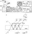
- FIG. 1Aillustrates the separation of reflected and transmitted images through a semi-transparent obstruction
- FIG. 1Billustrates imaging through haze using polarization analysis
- FIG. 1Cillustrates separating reflected and transmitted objects through a window using polarization analysis
- FIG. 1Dillustrates the use of polarization and color for material identification.
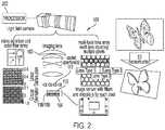
- FIG. 2schematically illustrates a light field camera architecture for measurement of color (red, green and blue), angle, and polarization of light (full Stokes), according to an illustrative embodiment of the invention.
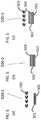
- FIG. 3shows a line drawing of a light field camera based on FIG. 2 .
- FIG. 4schematically illustrates an application of a plenoptic imaging system with active illumination.
- FIG. 5Aschematically illustrates a plenoptic imaging apparatus utilizing a coded aperture(s) and a micropolarizer sensor
- FIG. 5Bschematically illustrates a plenoptic imaging apparatus utilizing a microlens array and a micropolarizer sensor
- FIG. 5Cschematically illustrates a plenoptic imaging apparatus utilizing a microlens array, a coded aperture(s), and a micropolarizer sensor, according to exemplary embodiments of the invention.
- FIG. 6schematically illustrates a plenoptic imaging apparatus utilizing an imaging lens array, according to an exemplary embodiment of the invention.
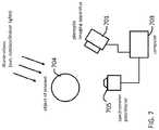
- FIG. 7schematically illustrates a plenoptic imaging apparatus utilizing passive illumination, according to an exemplary embodiment of the invention.
- FIG. 8schematically illustrates a plenoptic imaging apparatus utilizing both passive and active illumination, according to an exemplary embodiment of the invention.
- FIG. 9shows a schematic diagram of a sequence of data acquisition, according to an exemplary embodiment of the invention.
- FIGS. 1A-1Dillustrate that measurement of polarization information, such as the Stokes vector of a scene, permits the separation of reflected and transmitted light at different surfaces, thus providing important information about the material properties of the object, increases signal-to-noise ratio, and enables imaging of objects that are not in direct line of sight, partially occluded, or obscured by an opaque medium.
- polarization informationsuch as the Stokes vector of a scene
- FIGS. 2, 3, and 5A-5Cillustrate the architectures of three exemplary embodied polarization plenoptic imaging systems 100 .
- one of the exemplary embodimentsincludes coded aperture(s) and a micropolarizer sensor; another exemplary embodiment includes a microlens array and a micropolarizer sensor; and a third exemplary embodiment includes a microlens array, a coded aperture(s), and a micropolarizer sensor.
- an embodied polarization plenoptic imaging system 100 referred to as a division-of-focal-plane imagerincludes a focal plane array 104 that advantageously is a polarization sensitive focal plane array using a pixelated array of micropolarizers as known from U.S. Pat. No. 8,866,997 (or equivalent detector(s) such as division-of-amplitude detector using beam splitter and multiple sensors).
- a first microlens array 106is disposed on the object side of the detector pixel array 104 , advantageously directly on top of the pixel array for the purpose of collecting and focusing light onto each individual pixel.
- the first microlens array 106serves to cover and to collect light that falls outside of the light collection area of each pixel.
- the pitch of the first microlens arrayis advantageously the same as the pitch of the pixel array.
- the sensor pixel sizeis five (5) microns and is arranged in a square grid of pitch five (5) microns.
- the first microlens arrayhas a dimension equal to the pitch of the pixel array, which is also five (5) microns. This first microlens array is overlaid on the pixel array to increase the fill-factor of the detector array.
- the focal length of the first microlens arrayis advantageously substantially the same as the diameter of each microlens, which is five (5) microns.
- the plenoptic imaging system 100further includes micro-filter elements 108 disposed immediately in front of (i.e., object side) each detector pixel.
- the micro-filter elementsmay be color and polarization filters that advantageously are equal in size to a single pixel on the detector.
- An exemplary configurationuses four polarizer orientations (0°, 45°, 90°, and circular) and three color filters (red, green and blue) as illustrated in FIG. 2 . Examples of different filter configuration are described in Xingzhou Tu and Stanley Pau, Optimized design of N optical filters for color and polarization imaging , OPTICS EXPRESS, Vol. 24, No. 3 (2016).
- a second microlens array 110disposed on top of (i.e., object side) the micro-filter elements 108 at a fixed distance.
- the pitch of the second microlens array 110is larger and may typically be a multiple of ⁇ 10 to 100 times the pitch of the detector pixel array. In an example, the pitch is about 50 to 500 microns.
- the focal length of the second microlens arraymay be about one to two times the microlens dimension. In this example, the focal length may be 50 to 1000 microns.
- the second microlens array 110may comprise microlenses having different focal lengths, which enable imaging at a larger depth-of-focus than the case of using microlenses of a single focal length.
- imaging optics 102are disposed on the object side of the second microlens array at an appropriate distance.
- the second microlens array 110is replaced by one or more coded aperture mask(s) 112 disposed at carefully selected locations in front of the sensor.
- coded aperture mask(s)provide additional degrees of freedom for encoding the high-dimensional light field.
- Such encodingis especially advantageous as the polarization sensitive focal plane array makes a low-dimensional measurement of the encoded light field, which can then be inverted using appropriate regularization or priors using non-linear reconstruction algorithms to obtain a higher resolution estimate of the high-dimensional light field.
- the coded aperture(s)serves as a pre-conditioner that reduces the calculation difficulties of the inverse problem using appropriate regularization and constraints.
- coded aperturebenefits include potential multiplexing signal-to-noise (SNR) advantage and the capability to acquire multiple measurements of a light field, as well as adaptation of measurements to improve the light field quality further.
- SNRsignal-to-noise
- the coded aperture(s)can be made as phase-only structure(s), which leads to improved light collection efficiency for higher SNR performance of the camera.
- URAUniformly Redundant Array
- MURAModified Uniformly Redundant Array
- HURAHexagonal URA
- FZPFresnel Zone Plate
- random phase diffuserthat can be used to encode the light field in any plane between the lens (i.e., Fourier plane) and the focal plane array (i.e., image plane).
- the encoded light field measurement at the focal plane arraynow serves as an input to the inverse problem of recovering the light field at higher spatial and angular resolution by exploiting the inherent sparsity/compressibility of the natural light field.
- algorithms from the compressive sensing areathat can be used to solve this inverse problem, such as l1-minimization, LASSO, and TwIST to recover a high-resolution light field reconstruction.
- FIGS. 5A-5Cmore clearly illustrate the various embodied combinations of microlens arrays and coded apertures.
- FIG. 5Aschematically illustrates a plenoptic imaging apparatus 500 - 1 utilizing a coded aperture(s) 503 and a micropolarizer sensor 501 / 502 .
- FIG. 5Bschematically illustrates a plenoptic imaging apparatus 500 - 2 utilizing a microlens array 504 and a micropolarizer sensor 501 / 502 .
- FIG. 5Cschematically illustrates a plenoptic imaging apparatus 500 - 3 utilizing a microlens array 504 , a coded aperture(s) 503 , and a micropolarizer sensor 501 / 502 , according to exemplary embodiments of the invention.
- the embodied plenoptic imaging system(s)can operate in a natural light environment.
- the plenoptic imaging systemcan also or alternatively operate in ‘structured’ light; i.e., using an active illumination source 402 as illustrated in FIG. 4 .
- Both the illuminator and the plenoptic imaging apparatusare controlled by a computer 403 .
- the illumination source 402may be a simple light bulb, a light emitting diode, a laser, laser(s) with scanner, an image projector, or other structured illumination source as known in the art.
- the intensity, direction, color, polarization, coherence, and spatial/temporal profile of the light sourcecan be controlled to maximize signal-to-noise ratio in the image acquisition; for example, structured light can be projected onto the object of interest 404 and an image can be acquired using the embodied polarization plenoptic imaging system 401 .
- Structured lightcan have random or pseudorandom codifications, binary structured codifications, and N-ary codifications.
- the imaging opticsmay be a single lens that collects light from a scene onto the sensor as shown in FIG. 3 .
- the single lenscan be made of multiple elements and thus be bulky.
- the imaging opticsis a lens array 605 .
- This configuration of lens arraycan potentially be flatter than the configuration of a single lens.
- each lenscollects light from the scene from a different perspective onto the sensor 601 .
- the sensor raw datathen consists of an array of images, each coming from a lenslet in the lens array.
- each lens in the lens arraycan be made of multiple elements. Examples of lens array size can range from a 2 ⁇ 2 lens array to a 10 ⁇ 10 lens array. A 10 ⁇ 10 lens array allows simultaneously imaging of a scene at 100 different perspectives.
- FIG. 7Another embodiment of the application of the plenoptic imaging apparatus is shown in FIG. 7 .
- This configurationutilizes passive (natural) illumination.
- An object of interest 704is illuminated by natural light such as the sun or scattered light from the sky. Such light can be partially polarized and spectrally broad.
- the illuminationis not directly controlled by the user and the characteristic(s) of the illumination, such as wavelength, polarization, temporal and spatial profiles, is not known. This is especially true for the polarization state.
- the userneeds to know the state of the natural light. This state can be measured independently and simultaneously by a separate polarimeter and/or spectrometer 705 .
- the measurementcan be performed by a simple detector, a spectrometer, a polarimeter, or a combination.
- Light from the objectis measured by a plenoptic imaging apparatus 701 .
- Both the polarimeter/spectrometer and the plenoptic imaging apparatusare controlled by a computer 703 .
- Data from 705 and 701are measured and can provide a more faithful representation and 3D reconstruction of the object of interest 704 .
- FIG. 8Yet another embodiment of the application of the plenoptic imaging apparatus is shown in FIG. 8 .
- This configurationutilizes both active and passive illumination.
- An object of interest 804is illuminated by an illuminator 802 and natural light.
- the natural lightis measured by a polarimeter and/or spectrometer 805 .
- Light from the objectis measured by a plenoptic imaging apparatus 801 .
- the illuminator, polarimeter/spectrometer and the plenoptic imaging apparatusare controlled by a computer 803 .
- FIG. 9shows a schematic diagram 900 of a sequence of data acquisition.
- the active illuminatoris OFF and background light is measured using a spectrometer/polarimeter.
- the active illuminatoris turned ON.
- the reflected and transmitted light from the object of interestis measured using the plenoptic imaging apparatus and the spectrometer/polarimeter.
- data from the plenoptic imaging apparatus and the spectrometer/polarimeterare analyzed, and reflected light illuminated by the illuminator and reflected light from background light are separated.
- the active illuminator light outputis modified depending on the state of the passive illumination in order to improve the signal-to-noise ratio of the measurement.
- the reflected and transmitted light from the object of interestis again measured using the plenoptic imaging system.
- Light field camerashave been used for the purpose of depth measurement and 3D reconstruction of a scene.
- the cameracan capture both light ray directions and intensity in a single shot. This information can be used to re-focus an image at different depths and permits an estimation of a depth map of a scene.
- An example of an image processing algorithmincludes stereo matching of sub-aperture images to calculate distance and combination of depth cues based on defocus and correspondence to create high a resolution depth map. Numerous algorithms are known in the art.
- 3D scene reconstructionrequires the accurate measurement of the plenoptic function.
- the embodied polarization plenoptic cameraenables measurement properties of light rays including: (1) wavelength, by using color filters at the pixel level, (2) light direction, by using a microlens array(s) and/or coded apertures, and (3) polarization, by using a micropolarizer(s) at the pixel level.
- the embodimentsenable real time depth estimation of a moving object and can separate reflected and refracted images through polarization analysis.
- the embodied inventionadds new functionalities/information to existing plenoptic camera technology by measuring additional dimensions, spectral characterizations, and polarization of the light field with efficient, one-shot measurements.
Landscapes
- Engineering & Computer Science (AREA)
- Physics & Mathematics (AREA)
- General Physics & Mathematics (AREA)
- Theoretical Computer Science (AREA)
- Multimedia (AREA)
- Signal Processing (AREA)
- Computer Vision & Pattern Recognition (AREA)
- Optics & Photonics (AREA)
- Computing Systems (AREA)
- Studio Devices (AREA)
- Investigating Or Analysing Materials By Optical Means (AREA)
- Spectrometry And Color Measurement (AREA)
Abstract
Description
- wherein the second microlens array is characterized by a plurality of focal lengths;
- wherein the pitch of the second microlens array is between 10-100 times the pitch of the pixel array;
- wherein the coded aperture mask is a phase-only structure;
- wherein the division-of-focal plane architecture includes a plurality of color and polarization filters.
- further comprising an active illumination source adapted to illuminate the object scene;
- wherein the active illumination source has a user-controlled parameter including at least one of intensity, direction, color, polarization, coherence, spatial profile, and temporal profile.
- further comprising obtaining a single-shot measurement of a full Stokes vector at three spectral bands;
- further comprising illuminating the object scene with structured light from an active illumination source;
- further comprising adjusting at least one of intensity, direction, color, polarization, coherence, spatial profile, and temporal profile of the structured light.
Claims (11)
Priority Applications (1)
| Application Number | Priority Date | Filing Date | Title |
|---|---|---|---|
| US16/098,913US10783652B2 (en) | 2016-05-06 | 2017-05-03 | Plenoptic imaging apparatus, method, and applications |
Applications Claiming Priority (3)
| Application Number | Priority Date | Filing Date | Title |
|---|---|---|---|
| US201662332738P | 2016-05-06 | 2016-05-06 | |
| US16/098,913US10783652B2 (en) | 2016-05-06 | 2017-05-03 | Plenoptic imaging apparatus, method, and applications |
| PCT/US2017/030752WO2017192663A1 (en) | 2016-05-06 | 2017-05-03 | Plenoptic imaging apparatus, method, and applications |
Publications (2)
| Publication Number | Publication Date |
|---|---|
| US20190197714A1 US20190197714A1 (en) | 2019-06-27 |
| US10783652B2true US10783652B2 (en) | 2020-09-22 |
Family
ID=60203276
Family Applications (1)
| Application Number | Title | Priority Date | Filing Date |
|---|---|---|---|
| US16/098,913Expired - Fee RelatedUS10783652B2 (en) | 2016-05-06 | 2017-05-03 | Plenoptic imaging apparatus, method, and applications |
Country Status (2)
| Country | Link |
|---|---|
| US (1) | US10783652B2 (en) |
| WO (1) | WO2017192663A1 (en) |
Cited By (1)
| Publication number | Priority date | Publication date | Assignee | Title |
|---|---|---|---|---|
| US11546530B2 (en)* | 2018-10-19 | 2023-01-03 | Sony Corporation | Imaging device and solid-state imaging device |
Families Citing this family (9)
| Publication number | Priority date | Publication date | Assignee | Title |
|---|---|---|---|---|
| US10466036B2 (en) | 2016-10-07 | 2019-11-05 | Arizona Board Of Regents On Behalf Of The University Of Arizona | Attachable depth and orientation tracker device and method of depth and orientation tracking using focal plane polarization and color camera |
| IT201700050848A1 (en)* | 2017-05-10 | 2018-11-10 | Sisvel Tech S R L | METHODS AND APPARATUSES FOR ENCODING AND DECODING DIGITAL LIGHT FIELD IMAGES |
| WO2019104329A1 (en)* | 2017-11-27 | 2019-05-31 | Optecks, Llc | Medical three-dimensional (3d) scanning and mapping system |
| EP3783439A1 (en)* | 2019-08-22 | 2021-02-24 | ASML Netherlands B.V. | Metrology device and detection apparatus therefor |
| US11132757B2 (en) | 2019-08-27 | 2021-09-28 | Rosemount Aerospace Inc. | Secure image transmission |
| FR3105530B1 (en)* | 2019-12-24 | 2021-12-03 | Safran | SYSTEM AND METHOD FOR DETERMINING THE THREE-DIMENSIONAL PROFILE OF A SURFACE BY PLENOPTIC CAMERA AND STRUCTURED LIGHTING |
| CN111650759A (en)* | 2019-12-31 | 2020-09-11 | 北京大学 | Near-infrared spot projection multi-focal length microlens array remote sensing light field imaging system |
| CN114185170A (en) | 2020-09-14 | 2022-03-15 | 中强光电股份有限公司 | Near-eye light field display device |
| US20240323335A1 (en)* | 2021-10-05 | 2024-09-26 | Lg Electronics Inc. | Light capture device and light capture system including same |
Citations (13)
| Publication number | Priority date | Publication date | Assignee | Title |
|---|---|---|---|---|
| US20110069189A1 (en) | 2008-05-20 | 2011-03-24 | Pelican Imaging Corporation | Capturing and processing of images using monolithic camera array with heterogeneous imagers |
| US20110168903A1 (en)* | 2008-07-09 | 2011-07-14 | Nicholas Roberts Kyele | Beam Sensing |
| US20120038810A1 (en)* | 2009-03-17 | 2012-02-16 | Canon Kabushiki Kaisha | Image capturing apparatus |
| US20120075513A1 (en)* | 2009-06-11 | 2012-03-29 | Chipman Russell A | Microgrid imaging polarimeters with frequency domain reconstruction |
| US8238738B2 (en) | 2006-04-04 | 2012-08-07 | Adobe Systems Incorporated | Plenoptic camera |
| US8289440B2 (en) | 2008-12-08 | 2012-10-16 | Lytro, Inc. | Light field data acquisition devices, and methods of using and manufacturing same |
| US20120281072A1 (en) | 2009-07-15 | 2012-11-08 | Georgiev Todor G | Focused Plenoptic Camera Employing Different Apertures or Filtering at Different Microlenses |
| US8400555B1 (en)* | 2009-12-01 | 2013-03-19 | Adobe Systems Incorporated | Focused plenoptic camera employing microlenses with different focal lengths |
| US20130076910A1 (en) | 2011-09-22 | 2013-03-28 | Basil Henry Scott | Dual Pixel Pitch Imaging Array with Extended Dynamic Range |
| US20130265485A1 (en) | 2012-04-04 | 2013-10-10 | Samsung Electronics Co., Ltd. | Plenoptic camera apparatus |
| US8619177B2 (en) | 2009-04-22 | 2013-12-31 | Raytrix Gmbh | Digital imaging system, plenoptic optical device and image data processing method |
| US20140161363A1 (en)* | 2012-12-10 | 2014-06-12 | Edward Hartley Sargent | Sensors and systems for the capture of scenes and events in space and time |
| US8866997B2 (en) | 2010-11-02 | 2014-10-21 | Arizona Board Of Regents On Behalf Of The University Of Arizona | Patterned electronic and polarization optical devices |
- 2017
- 2017-05-03WOPCT/US2017/030752patent/WO2017192663A1/ennot_activeCeased
- 2017-05-03USUS16/098,913patent/US10783652B2/ennot_activeExpired - Fee Related
Patent Citations (13)
| Publication number | Priority date | Publication date | Assignee | Title |
|---|---|---|---|---|
| US8238738B2 (en) | 2006-04-04 | 2012-08-07 | Adobe Systems Incorporated | Plenoptic camera |
| US20110069189A1 (en) | 2008-05-20 | 2011-03-24 | Pelican Imaging Corporation | Capturing and processing of images using monolithic camera array with heterogeneous imagers |
| US20110168903A1 (en)* | 2008-07-09 | 2011-07-14 | Nicholas Roberts Kyele | Beam Sensing |
| US8289440B2 (en) | 2008-12-08 | 2012-10-16 | Lytro, Inc. | Light field data acquisition devices, and methods of using and manufacturing same |
| US20120038810A1 (en)* | 2009-03-17 | 2012-02-16 | Canon Kabushiki Kaisha | Image capturing apparatus |
| US8619177B2 (en) | 2009-04-22 | 2013-12-31 | Raytrix Gmbh | Digital imaging system, plenoptic optical device and image data processing method |
| US20120075513A1 (en)* | 2009-06-11 | 2012-03-29 | Chipman Russell A | Microgrid imaging polarimeters with frequency domain reconstruction |
| US20120281072A1 (en) | 2009-07-15 | 2012-11-08 | Georgiev Todor G | Focused Plenoptic Camera Employing Different Apertures or Filtering at Different Microlenses |
| US8400555B1 (en)* | 2009-12-01 | 2013-03-19 | Adobe Systems Incorporated | Focused plenoptic camera employing microlenses with different focal lengths |
| US8866997B2 (en) | 2010-11-02 | 2014-10-21 | Arizona Board Of Regents On Behalf Of The University Of Arizona | Patterned electronic and polarization optical devices |
| US20130076910A1 (en) | 2011-09-22 | 2013-03-28 | Basil Henry Scott | Dual Pixel Pitch Imaging Array with Extended Dynamic Range |
| US20130265485A1 (en) | 2012-04-04 | 2013-10-10 | Samsung Electronics Co., Ltd. | Plenoptic camera apparatus |
| US20140161363A1 (en)* | 2012-12-10 | 2014-06-12 | Edward Hartley Sargent | Sensors and systems for the capture of scenes and events in space and time |
Non-Patent Citations (19)
| Title |
|---|
| Ashok, Amit, et al. "Compressive light field imaging" In SPIE Defense, Security, and Sensing, pp. 76900Q-76900Q. International Society for Optics and Photonics, 2010. USA. |
| Ashok, Amit, et al., Pseudorandom phase masks for superresolution imaging from subpixel shifting, Applied Optics, vol. 46, No. 12, pp. 2256-2268, 2007. |
| Babacan, S. Derin, et al. "Compressive light field sensing" IEEE Transactions on Image Processing vol. 21, No. 12 (2012): pp. 4746-4757; copyright 2012 IEEE. |
| Bioucas-Dias, Jose M., et al., "A New TwIST: Two-Step Iterative Shrinkage/Thresholding Algorithms for Image Restoration", IEEE Transactions on Image Processing, pp. 1-12, Dec. 2007. |
| Candes, Emmaunuel et al., "Decoding by linear programming," in IEEE Transactions on Information Theory, vol. 51, No. 12, pp. 4203-4215, Dec. 2005. |
| Fenimore, E.E., et al., Coded aperture imaging with uniformly redundant arrays, Applied Optics, vol. 17, No. 3, pp. 337-347, copyright 1978 Optical Society of America. |
| Finger, M.H., et al., Hexagonal Uniformly Redundant Arrays for Coded-Aperture Imaging, Proc. 19th Int. Cosmic Ray Conf. (Scientific and Technical Information Branch, NASA, Washington, DC), pp. 295-298, 1985. |
| Fresnel, A., Calcul de l'intensite de la lumiere au centre de l'ombre d'un ecran, Oeuvres completes d' Augustin Fresnel, vol. 1, Note 1, p. 365, 1866. |
| Gottesman, Stephen R., et al., New family of binary arrays for coded aperture imaging, Applied Optics, vol. 28 No. 20, pp. 4344-4352, copyright 1989 Optical Society of America. |
| H. G. Jeon et al.; Accurate Depth Map Estimation from a Lenslet Light Field Camera; 2015 IEEE Conference on Computer Vision and Pattern Recognition (CVPR), Jun. 7-12, 2015, pp. 1547-1555. |
| Jeon, Hae-Gon et al., Accurate Depth Map Estimation from a Lenslet Light Field Camera, IEEE Conference on Computer Vision and Pattern Recognition, pp. 1547-1555, Jun. 2015. |
| Marwah, Kshitij, et al. "Compressive Light Field Photography using Overcomplete Dictionaries and Optimized Projections." ACM Transactions on Graphics (TOG) 32, No. 4 (2013): 46. USA. |
| Notification of Transmittal, International Search Report, and Written Opinion for PCT Application No. PCT/US2017/030752; Forms PCT/ISA/220, PCT/ISA/210, and PCT/ISA/237; dated Sep. 1, 2017; 10 pages. |
| Salahieh, Basel, et al. "Compressive Light Field Imaging Using Joint Spatio-Angular Modulation." In Computational Optical Sensing and Imaging, pp. CM4C-6. Optical Society of America, 2013. USA. |
| Tao, Michael W., et al., Depth from combining defocus and correspondence using light-field cameras, IEEE International Conference on Computer Vision, pp. 673-680, copyright 2013 IEEE. |
| Tibshirani, Robert, "Regression Shrinkage and Selection via the Lasso," Journal of the Royal Statistical Society Series B, vol. 58, No. 1, pp. 267-288, 1996. |
| Tu, Xingzhou et al.; Optimized design of N optical filters for color and polarization imaging; Feb. 8, 2016; vol. 24, No. 3, Optics Express pp. 3011-3024; Copyright 2016 OSA. |
| Y. Y. Schechner, Inversion by P4: polarization-picture post-processing, Phil. Trans. R. Soc. B 2011 366, pp. 638-648; copyright 2011 The Royal Society. |
| Zhang, Song, High-speed 3D Imaging with Digital Fringe Projection Techniques, chapter 1, CRC Press, 2016. |
Cited By (1)
| Publication number | Priority date | Publication date | Assignee | Title |
|---|---|---|---|---|
| US11546530B2 (en)* | 2018-10-19 | 2023-01-03 | Sony Corporation | Imaging device and solid-state imaging device |
Also Published As
| Publication number | Publication date |
|---|---|
| WO2017192663A1 (en) | 2017-11-09 |
| US20190197714A1 (en) | 2019-06-27 |
Similar Documents
| Publication | Publication Date | Title |
|---|---|---|
| US10783652B2 (en) | Plenoptic imaging apparatus, method, and applications | |
| US20220057550A1 (en) | Light Field Imaging Device and Method for Depth Acquisition and Three-Dimensional Imaging | |
| JP6260006B2 (en) | IMAGING DEVICE, IMAGING SYSTEM USING THE SAME, ELECTRONIC MIRROR SYSTEM, AND RANGING DEVICE | |
| CN107271039B (en) | Compact miniature fast illuminated spectral imaging detecting device and detection method | |
| KR102040368B1 (en) | Hyper spectral image sensor and 3D Scanner using it | |
| CN102944305B (en) | Spectral imaging method and spectrum imaging instrument of snapshot-type high throughput | |
| US8427632B1 (en) | Image sensor with laser for range measurements | |
| US20090185173A1 (en) | Apparatus and method for determining characteristics of a light source | |
| CN103323113B (en) | Multispectral imager based on light fieldd imaging technique | |
| US20170276545A1 (en) | An imaging system parallelizing compressive sensing imaging | |
| US9347832B2 (en) | Optical systems and methods employing a polarimetric optical filter | |
| US9945721B2 (en) | Selective wavelength imaging systems and methods | |
| CN106872037B (en) | Fast illuminated compact optical field imaging full-polarization spectrum detection device and method | |
| TW201925860A (en) | Light field image processing method for depth acquisition | |
| CN103472592A (en) | Snapping type high-flux polarization imaging method and polarization imager | |
| KR20190076998A (en) | Apparatus and method for obtaining distance information from a view | |
| US20140098212A1 (en) | Image capturing device and image capturing system | |
| CN108088564A (en) | A kind of fast illuminated light field-polarization imager and imaging method | |
| WO2015157097A1 (en) | Low-power image change detector | |
| Baek et al. | Lensless polarization camera for single-shot full-Stokes imaging | |
| CN108088561A (en) | A kind of fast illuminated light field-optical spectrum imagers and imaging method | |
| RU2580870C2 (en) | High-resolution imaging system | |
| CN106949967A (en) | The fast compact channel modulation type optical field imaging full-polarization spectrum detection device of illuminated and method | |
| WO2021099761A1 (en) | Imaging apparatus | |
| JP6941124B2 (en) | Fourier Transform Multi-Channel Spectrum Imager |
Legal Events
| Date | Code | Title | Description |
|---|---|---|---|
| AS | Assignment | Owner name:ARIZONA BOARD OF REGENTS ON BEHALF OF THE UNIVERSI Free format text:ASSIGNMENT OF ASSIGNORS INTEREST;ASSIGNORS:PAU, STANLEY;ASHOK, AMIT;REEL/FRAME:047408/0668 Effective date:20170504 Owner name:ARIZONA BOARD OF REGENTS ON BEHALF OF THE UNIVERSITY OF ARIZONA, ARIZONA Free format text:ASSIGNMENT OF ASSIGNORS INTEREST;ASSIGNORS:PAU, STANLEY;ASHOK, AMIT;REEL/FRAME:047408/0668 Effective date:20170504 | |
| FEPP | Fee payment procedure | Free format text:ENTITY STATUS SET TO UNDISCOUNTED (ORIGINAL EVENT CODE: BIG.); ENTITY STATUS OF PATENT OWNER: SMALL ENTITY | |
| FEPP | Fee payment procedure | Free format text:ENTITY STATUS SET TO SMALL (ORIGINAL EVENT CODE: SMAL); ENTITY STATUS OF PATENT OWNER: SMALL ENTITY | |
| STPP | Information on status: patent application and granting procedure in general | Free format text:DOCKETED NEW CASE - READY FOR EXAMINATION | |
| STPP | Information on status: patent application and granting procedure in general | Free format text:NON FINAL ACTION MAILED | |
| STPP | Information on status: patent application and granting procedure in general | Free format text:RESPONSE TO NON-FINAL OFFICE ACTION ENTERED AND FORWARDED TO EXAMINER | |
| STPP | Information on status: patent application and granting procedure in general | Free format text:FINAL REJECTION MAILED | |
| STPP | Information on status: patent application and granting procedure in general | Free format text:DOCKETED NEW CASE - READY FOR EXAMINATION | |
| STPP | Information on status: patent application and granting procedure in general | Free format text:PUBLICATIONS -- ISSUE FEE PAYMENT VERIFIED | |
| STCF | Information on status: patent grant | Free format text:PATENTED CASE | |
| FEPP | Fee payment procedure | Free format text:MAINTENANCE FEE REMINDER MAILED (ORIGINAL EVENT CODE: REM.); ENTITY STATUS OF PATENT OWNER: SMALL ENTITY | |
| LAPS | Lapse for failure to pay maintenance fees | Free format text:PATENT EXPIRED FOR FAILURE TO PAY MAINTENANCE FEES (ORIGINAL EVENT CODE: EXP.); ENTITY STATUS OF PATENT OWNER: SMALL ENTITY | |
| STCH | Information on status: patent discontinuation | Free format text:PATENT EXPIRED DUE TO NONPAYMENT OF MAINTENANCE FEES UNDER 37 CFR 1.362 | |
| FP | Lapsed due to failure to pay maintenance fee | Effective date:20240922 |