US10782487B2 - Multi-fiber fiber optic connector - Google Patents
Multi-fiber fiber optic connectorDownload PDFInfo
- Publication number
- US10782487B2 US10782487B2US16/599,833US201916599833AUS10782487B2US 10782487 B2US10782487 B2US 10782487B2US 201916599833 AUS201916599833 AUS 201916599833AUS 10782487 B2US10782487 B2US 10782487B2
- Authority
- US
- United States
- Prior art keywords
- connector
- connector body
- fiber optic
- ferrule
- cable
- Prior art date
- Legal status (The legal status is an assumption and is not a legal conclusion. Google has not performed a legal analysis and makes no representation as to the accuracy of the status listed.)
- Active
Links
- 239000000835fiberSubstances0.000titleclaimsabstractdescription195
- 239000013307optical fiberSubstances0.000claimsdescription55
- 230000003014reinforcing effectEffects0.000claimsdescription14
- 239000002184metalSubstances0.000claimsdescription9
- 230000006835compressionEffects0.000claimsdescription5
- 238000007906compressionMethods0.000claimsdescription5
- 230000007613environmental effectEffects0.000claims1
- 230000037431insertionEffects0.000abstract1
- 238000003780insertionMethods0.000abstract1
- 230000003287optical effectEffects0.000description8
- 238000004891communicationMethods0.000description6
- 230000000712assemblyEffects0.000description4
- 238000000429assemblyMethods0.000description4
- 239000011159matrix materialSubstances0.000description4
- 238000010276constructionMethods0.000description3
- 239000010410layerSubstances0.000description3
- 239000000853adhesiveSubstances0.000description2
- 230000001070adhesive effectEffects0.000description2
- 239000012790adhesive layerSubstances0.000description2
- 239000011230binding agentSubstances0.000description2
- 230000004927fusionEffects0.000description2
- 239000011521glassSubstances0.000description2
- 230000014759maintenance of locationEffects0.000description2
- 238000000034methodMethods0.000description2
- 238000012986modificationMethods0.000description2
- 230000004048modificationEffects0.000description2
- 230000008569processEffects0.000description2
- 239000004593EpoxySubstances0.000description1
- 229910000831SteelInorganic materials0.000description1
- 238000004873anchoringMethods0.000description1
- 239000004760aramidSubstances0.000description1
- 229920006231aramid fiberPolymers0.000description1
- 230000008901benefitEffects0.000description1
- 239000000356contaminantSubstances0.000description1
- 230000008878couplingEffects0.000description1
- 238000010168coupling processMethods0.000description1
- 238000005859coupling reactionMethods0.000description1
- 239000000428dustSubstances0.000description1
- 238000009434installationMethods0.000description1
- 238000011900installation processMethods0.000description1
- 239000000463materialSubstances0.000description1
- 239000002991molded plasticSubstances0.000description1
- 229920000642polymerPolymers0.000description1
- 230000002787reinforcementEffects0.000description1
- 229910001220stainless steelInorganic materials0.000description1
- 239000010935stainless steelSubstances0.000description1
- 239000010959steelSubstances0.000description1
- XLYOFNOQVPJJNP-UHFFFAOYSA-NwaterSubstancesOXLYOFNOQVPJJNP-UHFFFAOYSA-N0.000description1
Images


Classifications
- G—PHYSICS
- G02—OPTICS
- G02B—OPTICAL ELEMENTS, SYSTEMS OR APPARATUS
- G02B6/00—Light guides; Structural details of arrangements comprising light guides and other optical elements, e.g. couplings
- G02B6/24—Coupling light guides
- G02B6/36—Mechanical coupling means
- G02B6/38—Mechanical coupling means having fibre to fibre mating means
- G02B6/3807—Dismountable connectors, i.e. comprising plugs
- G02B6/3873—Connectors using guide surfaces for aligning ferrule ends, e.g. tubes, sleeves, V-grooves, rods, pins, balls
- G02B6/3885—Multicore or multichannel optical connectors, i.e. one single ferrule containing more than one fibre, e.g. ribbon type
- G—PHYSICS
- G02—OPTICS
- G02B—OPTICAL ELEMENTS, SYSTEMS OR APPARATUS
- G02B6/00—Light guides; Structural details of arrangements comprising light guides and other optical elements, e.g. couplings
- G02B6/24—Coupling light guides
- G02B6/36—Mechanical coupling means
- G02B6/38—Mechanical coupling means having fibre to fibre mating means
- G02B6/3807—Dismountable connectors, i.e. comprising plugs
- G02B6/3869—Mounting ferrules to connector body, i.e. plugs
- G—PHYSICS
- G02—OPTICS
- G02B—OPTICAL ELEMENTS, SYSTEMS OR APPARATUS
- G02B6/00—Light guides; Structural details of arrangements comprising light guides and other optical elements, e.g. couplings
- G02B6/24—Coupling light guides
- G02B6/36—Mechanical coupling means
- G02B6/38—Mechanical coupling means having fibre to fibre mating means
- G02B6/3807—Dismountable connectors, i.e. comprising plugs
- G02B6/3887—Anchoring optical cables to connector housings, e.g. strain relief features
- G02B6/3888—Protection from over-extension or over-compression
- G—PHYSICS
- G02—OPTICS
- G02B—OPTICAL ELEMENTS, SYSTEMS OR APPARATUS
- G02B6/00—Light guides; Structural details of arrangements comprising light guides and other optical elements, e.g. couplings
- G02B6/44—Mechanical structures for providing tensile strength and external protection for fibres, e.g. optical transmission cables
- G02B6/4401—Optical cables
- G02B6/4403—Optical cables with ribbon structure
- G—PHYSICS
- G02—OPTICS
- G02B—OPTICAL ELEMENTS, SYSTEMS OR APPARATUS
- G02B6/00—Light guides; Structural details of arrangements comprising light guides and other optical elements, e.g. couplings
- G02B6/44—Mechanical structures for providing tensile strength and external protection for fibres, e.g. optical transmission cables
- G02B6/4401—Optical cables
- G02B6/4429—Means specially adapted for strengthening or protecting the cables
- G—PHYSICS
- G02—OPTICS
- G02B—OPTICAL ELEMENTS, SYSTEMS OR APPARATUS
- G02B6/00—Light guides; Structural details of arrangements comprising light guides and other optical elements, e.g. couplings
- G02B6/24—Coupling light guides
- G02B6/255—Splicing of light guides, e.g. by fusion or bonding
- G02B6/2558—Reinforcement of splice joint
- G—PHYSICS
- G02—OPTICS
- G02B—OPTICAL ELEMENTS, SYSTEMS OR APPARATUS
- G02B6/00—Light guides; Structural details of arrangements comprising light guides and other optical elements, e.g. couplings
- G02B6/24—Coupling light guides
- G02B6/36—Mechanical coupling means
- G02B6/38—Mechanical coupling means having fibre to fibre mating means
- G02B6/3807—Dismountable connectors, i.e. comprising plugs
- G02B6/381—Dismountable connectors, i.e. comprising plugs of the ferrule type, e.g. fibre ends embedded in ferrules, connecting a pair of fibres
- G02B6/3818—Dismountable connectors, i.e. comprising plugs of the ferrule type, e.g. fibre ends embedded in ferrules, connecting a pair of fibres of a low-reflection-loss type
- G02B6/3821—Dismountable connectors, i.e. comprising plugs of the ferrule type, e.g. fibre ends embedded in ferrules, connecting a pair of fibres of a low-reflection-loss type with axial spring biasing or loading means
- G—PHYSICS
- G02—OPTICS
- G02B—OPTICAL ELEMENTS, SYSTEMS OR APPARATUS
- G02B6/00—Light guides; Structural details of arrangements comprising light guides and other optical elements, e.g. couplings
- G02B6/24—Coupling light guides
- G02B6/36—Mechanical coupling means
- G02B6/38—Mechanical coupling means having fibre to fibre mating means
- G02B6/3807—Dismountable connectors, i.e. comprising plugs
- G02B6/381—Dismountable connectors, i.e. comprising plugs of the ferrule type, e.g. fibre ends embedded in ferrules, connecting a pair of fibres
- G02B6/3825—Dismountable connectors, i.e. comprising plugs of the ferrule type, e.g. fibre ends embedded in ferrules, connecting a pair of fibres with an intermediate part, e.g. adapter, receptacle, linking two plugs
- G—PHYSICS
- G02—OPTICS
- G02B—OPTICAL ELEMENTS, SYSTEMS OR APPARATUS
- G02B6/00—Light guides; Structural details of arrangements comprising light guides and other optical elements, e.g. couplings
- G02B6/24—Coupling light guides
- G02B6/36—Mechanical coupling means
- G02B6/38—Mechanical coupling means having fibre to fibre mating means
- G02B6/3807—Dismountable connectors, i.e. comprising plugs
- G02B6/3833—Details of mounting fibres in ferrules; Assembly methods; Manufacture
- G02B6/3846—Details of mounting fibres in ferrules; Assembly methods; Manufacture with fibre stubs
- G—PHYSICS
- G02—OPTICS
- G02B—OPTICAL ELEMENTS, SYSTEMS OR APPARATUS
- G02B6/00—Light guides; Structural details of arrangements comprising light guides and other optical elements, e.g. couplings
- G02B6/24—Coupling light guides
- G02B6/36—Mechanical coupling means
- G02B6/38—Mechanical coupling means having fibre to fibre mating means
- G02B6/3807—Dismountable connectors, i.e. comprising plugs
- G02B6/3869—Mounting ferrules to connector body, i.e. plugs
- G02B6/387—Connector plugs comprising two complementary members, e.g. shells, caps, covers, locked together
- G—PHYSICS
- G02—OPTICS
- G02B—OPTICAL ELEMENTS, SYSTEMS OR APPARATUS
- G02B6/00—Light guides; Structural details of arrangements comprising light guides and other optical elements, e.g. couplings
- G02B6/24—Coupling light guides
- G02B6/36—Mechanical coupling means
- G02B6/38—Mechanical coupling means having fibre to fibre mating means
- G02B6/3807—Dismountable connectors, i.e. comprising plugs
- G02B6/3887—Anchoring optical cables to connector housings, e.g. strain relief features
- G02B6/3889—Anchoring optical cables to connector housings, e.g. strain relief features using encapsulation for protection, e.g. adhesive, molding or casting resin
- G—PHYSICS
- G02—OPTICS
- G02B—OPTICAL ELEMENTS, SYSTEMS OR APPARATUS
- G02B6/00—Light guides; Structural details of arrangements comprising light guides and other optical elements, e.g. couplings
- G02B6/24—Coupling light guides
- G02B6/36—Mechanical coupling means
- G02B6/38—Mechanical coupling means having fibre to fibre mating means
- G02B6/3807—Dismountable connectors, i.e. comprising plugs
- G02B6/389—Dismountable connectors, i.e. comprising plugs characterised by the method of fastening connecting plugs and sockets, e.g. screw- or nut-lock, snap-in, bayonet type
- G02B6/3891—Bayonet type
- G—PHYSICS
- G02—OPTICS
- G02B—OPTICAL ELEMENTS, SYSTEMS OR APPARATUS
- G02B6/00—Light guides; Structural details of arrangements comprising light guides and other optical elements, e.g. couplings
- G02B6/24—Coupling light guides
- G02B6/36—Mechanical coupling means
- G02B6/38—Mechanical coupling means having fibre to fibre mating means
- G02B6/3807—Dismountable connectors, i.e. comprising plugs
- G02B6/389—Dismountable connectors, i.e. comprising plugs characterised by the method of fastening connecting plugs and sockets, e.g. screw- or nut-lock, snap-in, bayonet type
- G02B6/3894—Screw-lock type
- G—PHYSICS
- G02—OPTICS
- G02B—OPTICAL ELEMENTS, SYSTEMS OR APPARATUS
- G02B6/00—Light guides; Structural details of arrangements comprising light guides and other optical elements, e.g. couplings
- G02B6/24—Coupling light guides
- G02B6/36—Mechanical coupling means
- G02B6/40—Mechanical coupling means having fibre bundle mating means
- G02B6/406—Mechanical coupling means having fibre bundle mating means of the ferrule type, connecting a plurality of pairs of ferrules
- G—PHYSICS
- G02—OPTICS
- G02B—OPTICAL ELEMENTS, SYSTEMS OR APPARATUS
- G02B6/00—Light guides; Structural details of arrangements comprising light guides and other optical elements, e.g. couplings
- G02B6/44—Mechanical structures for providing tensile strength and external protection for fibres, e.g. optical transmission cables
- G02B6/4401—Optical cables
- G02B6/4429—Means specially adapted for strengthening or protecting the cables
- G02B6/44384—Means specially adapted for strengthening or protecting the cables the means comprising water blocking or hydrophobic materials
Definitions
- the present disclosurerelates generally to optical fiber communication systems. More particularly, the present disclosure relates to fiber optic connectors used in optical fiber communication systems.
- Fiber optic communication systemsare becoming prevalent in part because service providers want to deliver high bandwidth communication capabilities (e.g., data and voice) to customers.
- Fiber optic communication systemsemploy a network of fiber optic cables to transmit large volumes of data and voice signals over relatively long distances.
- Optical fiber connectorsare an important part of most fiber optic communication systems. Fiber optic connectors allow two optical fibers to be quickly optically connected without requiring a splice. Fiber optic connectors can be used to optically interconnect two lengths of optical fiber. Fiber optic connectors can also be used to interconnect lengths of optical fiber to passive and active equipment.
- a typical fiber optic connectorincludes a ferrule assembly supported at a distal end of a connector housing.
- a springis used to bias the ferrule assembly in a distal direction relative to the connector housing.
- the ferrulefunctions to support an end portion of at least one optical fiber (in the case of a multi-fiber ferrule, the ends of multiple fibers are supported).
- the ferrulehas a distal end face at which a polished end of the optical fiber is located.
- connection systemshave been developed for use in outside environments. Such connection systems typically have a ruggedized/hardened construction adapted for accommodating substantial pull-out forces. Such connection systems are also typically sealed to limit moisture intrusion.
- Example fiber optic connection systems adapted for outside useare disclosed in U.S. Pat. Nos. 6,648,520, 7,264,402, 7,572,065, 7,744,288, 7,762,726, 7,744,286, 7,942,590.
- Multi-fiber connectorscan include splice-on configurations and direct termination configurations.
- a splice-on configurationoptical fibers are pre-terminated within a multi-fiber ferrule and the end face of the ferrule is processed (e.g., polished and shaped as needed). After processing of the ferrule, the optical fibers have polished end faces at a front of the ferrule and also have pigtails that project rearwardly from the ferrule.
- the multi-fiber ferruleis loaded into a connector and the pigtails are spliced to optical fibers corresponding to a fiber optic cable desired to be coupled to the connector.
- the splice locationis positioned rearward of the connector (e.g., see U.S.
- One aspect of the present disclosurerelates to a multi-fiber connector that accommodates both spliced-on and direct termination configurations.
- a ferrulecan be mounted directly at ends of the optical fibers of the cable, the ferrule end face can be processed (e.g., polished, shaped, etc.) and then the cable and ferrule assembly can be loaded into the connector body.
- optical fibersare pre-installed in the ferrule and the ferrule is processed. Thereafter, the pigtails of the optical fibers are spliced to the fibers of an optical cable and then the assembly is loaded into the connector body.
- Certain example types of fiber optic cable assembliesinclude a fiber optic cable and a fiber optic connector.
- the fiber optic cableincludes a jacket having an elongated transverse cross-sectional profile that defines a major axis and a minor axis. The major and minor axes of the jacket are generally perpendicular relative to one another.
- the fiber optic cablealso includes optical fibers contained within the jacket.
- the fiber optic cablealso includes first and second strength components positioned on opposite sides of the optical fibers. The first and second strength components are anchored relative to the fiber optic connector, which includes a connector body in which a multi-fiber ferrule is mounted. The multi-fiber ferrule defines a major axis and a minor axis.
- the major and minor axes of the multi-fiber ferrule axisare generally perpendicular relative to one another.
- the major axis of the multi-fiber ferruleis generally perpendicular to the major axis of the jacket and the minor axis of the multi-fiber ferrule is generally perpendicular to the minor axis of the jacket.
- the multi-fiber ferrulecan be side loaded into the fiber optic connector.
- Certain example types of fiber optic connectorsinclude a connector body, a multi-fiber ferrule that mounts at a front end of the connector body, and a cover.
- the connector bodyhas a length that extends along an axis of the connector body.
- the connector bodyincludes front and rear ends separated by the length of the connector body.
- the connector bodyalso defines a side opening that extends along the length of the connector body. The side opening is arranged and configured for allowing the multi-fiber ferrule to be inserted laterally into the connector body through the side opening.
- the covermounts over the side opening after the multi-fiber ferrule has been inserted into the connector body through the side opening.
- FIG. 1is a perspective view of a first example hardened multi-fiber cable assembly in accordance with the principles of the present disclosure, and adapter is shown coupling the first cable assembly to a second example cable assembly terminated by a multi-fiber connector;
- FIG. 2is a cross-sectional view of an example fiber optic cable having a major axis and a minor axis;
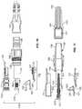
- FIG. 3is an exploded view of the components of the first and second cable assemblies shown in FIG. 1 ;
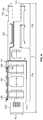
- FIG. 4is a top plan view of an example connector including a connector body, a spring-biased multi-fiber ferrule, and a cover;
- FIG. 5is a perspective view of the example connector of FIG. 4 shows in the cover exploded from a side opening in the connector body;
- FIG. 6is a perspective view of a portion of the example hardened connector arrangement of FIG. 3 including the connector of FIG. 4 with a portion of the cover exploded to reveal part of the interior of the connector body, a front end piece exploded forwardly of the connector body to reveal optical fiber portions, and the multi-fiber ferrule exploded outwardly and rotated 90°;
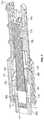
- FIG. 7is an axial cross-sectional view of the connector of FIG. 4 ;
- FIG. 8is an enlarged view of a cross-section of the example hardened connector arrangement of FIG. 1 showing the ferrule extending outwardly through the connector body;
- FIG. 9shows the view of the example hardened connector arrangement of FIG. 8 rotated 90°
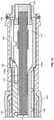
- FIG. 10is a bottom plan view of the example hardened connector arrangement of FIG. 3 with various components exploded outwardly including the connector body, the cover, and the strain-relief boot;
- FIG. 11is an axial cross-sectional view of the example hardened connector arrangement shown in FIG. 10 ;
- FIG. 12is an enlarged, cross-sectional view of the example hardened connector arrangement of FIG. 3 shown assembled and with a rear portion of the cable fibers and the strength components removed from view;
- FIG. 13is a perspective view of a lateral cross-section of the example hardened connector arrangement of FIG. 1 taken along the 13 - 13 line of FIG. 1 ;
- FIG. 13Ais a front elevational view of ribbonized fibers recoated in a matrix material
- FIG. 14is a perspective view of a lateral cross-section of the example hardened connector arrangement of FIG. 1 taken along the 14 - 14 line of FIG. 1 ;
- FIG. 15is an axial cross-sectional view of the example hardened connector arrangement of FIG. 3 shown assembled and with a rear portion of the cable fibers and the strength components removed from view;
- FIG. 16is a perspective view of an enlarged section of an example optical cable 400 , which has a plurality of optical fibers 410 formed in a ribbon and a protection plate, suitable for use in the of fiber optic cable assemblies disclosed herein; and
- FIGS. 17-19are various views of an example protection plate suitable for use in the cable shown in FIG. 16 .
- fiber optic cable assemblies 100including a fiber optic cable 105 terminated by a fiber optic connector 110 ( FIG. 3 ).
- the fiber optic connector 110may be part of a hardened (i.e., environmentally sealed) fiber optic connector arrangement 108 .
- the fiber optic connector arrangement 108is configured to interface with a second fiber optic cable assembly 200 .
- the second fiber optic cable assembly 200includes a multi-fiber connector 210 terminating a second fiber optic cable 205 .
- the fiber optic connector arrangement 108is configured to couple to a fiber optic adapter 150 to enable connection to the fiber optic connector 210 of the second fiber optic cable assembly 200 .
- the example adapter 150enables a first fiber optic connector 110 , which terminates a first optical cable 105 , to mate with a second optic connector 210 , which terminates a second optical cable 205 .
- the adapter 150defines a socket configured to receive a connectorized end of the second cable assembly 200 .
- the fiber optic adapter 150is configured to mount within an opening defined in a wall, plate, enclosure, or other structure.
- the fiber optic connector arrangement 108is a hardened (i.e., environmentally sealed) fiber optic connector arrangement 108 .
- the adapter 150is a hardened (i.e., environmentally sealed) adapter.
- the adapter 150enables the hardened fiber optic connector arrangement 108 to mate with a non-hardened (i.e., unsealed) fiber optic connector 210 .
- the adapter 150 coupled to the hardened fiber optic connector arrangement 108is configured to receive a non-hardened fiber optic connector 210 (e.g., an MPO connector).
- a non-hardened fiber optic connector 210e.g., an MPO connector
- Certain types of hardened fiber optic connector arrangements 108are configured to mate with other hardened fiber optic connector arrangements (e.g., in a plug and receptacle style connection).
- FIG. 2shows one example fiber optic cable 105 including one or more optical fibers 106 surrounded by an outer jacket 107 .
- the outer jacket 107has an elongated transverse cross-sectional profile defining a major axis A 1 and a minor axis A 2 .
- the transverse cross-sectional profile defined by the outer jacket 107is generally rectangular with rounded ends.
- the major axis A 1 and the minor axis A 2intersect perpendicularly at a lengthwise axis of the cable 105 .
- the transverse cross-sectional profilehas maximum width that extends along the major axis A 1 and a maximum thickness that extends along the minor axis A 2 .
- the maximum width of the transverse cross-sectional profileis longer than the maximum thickness of the transverse cross-sectional profile.
- the fiber optic cable 105is a flat drop cable.
- the first and second optical cables 105 , 205include multiple optical fibers.
- the fiber optic connectors 110 , 210are configured to terminate multiple fibers.
- one or both of the optical cables 105 , 205include only a single optical fiber.
- the outer jacket 107also defines a first passage 109 that extends through the outer jacket 107 along a lengthwise axis of the outer jacket 107 .
- the optical fibers 106are disposed loose in the first passage 109 .
- the optical fibers 106may be ribbonized, buffered, or otherwise contained within the passage 109 .
- the fiber optic cable 105includes twelve optical fibers 106 . In other implementations, however, the fiber optic cable 105 may include a greater or lesser number of optical fibers 106 (e.g., one fiber, two fibers, six fibers, ten fibers, fifteen fibers, twenty-four fibers, etc.).
- At least one strength component 170also extends through the outer jacket 107 along a lengthwise axis of the outer jacket 107 .
- first and second strength components 170are disposed on opposite sides of the first passage 109 along the major axis A 1 .
- example fiber optic cables 105may include a single strength component 170 .
- example fiber optic cables 105may include additional strength components 170 .
- each strength components 108is formed by a layer of reinforcing elements (e.g., fibers or yarns such as aramid fibers or yarns) embedded or otherwise integrated within a binder to form a reinforcing structure.
- each strength component 170can have a glass reinforced polymer (GRP) construction.
- GRPglass reinforced polymer
- the strength component 170has a round cross-sectional profile.
- the cross-sectional profile of the strength component 170may be any desired shape (e.g., rectangular, oblong, obround, etc.).
- Other example cable configurationsare disclosed in U.S. Pat. No. 8,041,166, the disclosure of which is hereby incorporated herein by reference.
- FIG. 3shows an exploded view of the example fiber optic connector arrangement 108 of FIG. 1 .
- the example fiber optic connector arrangement 108includes a fiber optic connector 110 having a body 111 and a spring-biased ferrule 510 .
- a metal reinforcing sleeve 131mounts over a rear portion 115 of the connector body 111 .
- the metal reinforcing sleeve 131includes a main sleeve body 132 and a lip 133 that projects radially outwardly from the main sleeve body 132 .
- the lip 133has a rearwardly facing surface 133 a ( FIG. 15 ).
- An outermost sleeve 134mounts over the metal reinforcing sleeve 131 .
- the outermost sleeve 134includes an internal shoulder having a forwardly facing surface 134 a ( FIG. 15 ) that abuts the rearwardly facing surface 133 a of the lip 133 to limit rearward movement of the reinforcing sleeve 131 relative to the outermost sleeve 134 (see FIG. 15 ).
- the outermost sleeve 134defines keying features 135 that mate with corresponding keying features 135 b of the connector body 111 to ensure proper rotational alignment before the parts when the parts are assembled together.
- the connector body 111 and the outermost sleeve 134have a molded plastic construction.
- An external seal (e.g., an O-ring) 139mounts about the outermost sleeve 134 (see FIGS. 8, 9, and 12 ).
- the seal 139provides protection against water, dust, or other contaminants when the hardened connector arrangement 108 is mated with another component.
- a front end piece 130mounts at the front end 112 of the connector body 111 and connects to the outermost sleeve 134 such that the outermost sleeve 134 and the front end piece 130 are secured in place relative to the connector body 111 (i.e., the connector body 111 is captured between the pieces).
- the front end piece 130snap-fits to the outermost sleeve 134 .
- the front end piece 130otherwise couples to the outermost sleeve 134 .
- Keying features 135 c of the front end piece 130may align with keying features 135 a of the outermost sleeve 134 to ensure rotational alignment thereinbetween.
- the front end piece 130defines a through-opening through which a ferrule 510 of the connector 110 passes.
- a shrink tube 140(e.g., a shrink fit tube having a heat recoverable layer surrounding an adhesive layer as disclosed in U.S. Pat. No. 5,470,622, the disclosure of which is hereby incorporated by reference herein) and a strain-relief boot 143 protect the optical fibers 106 of the cable 105 as the cable exits the connector arrangement 108 .
- the shrink tube 140has a forward section 141 that is configured to adherently attach over a rearward section 136 of the outmost sleeve 134 and a rearward section 142 that is configured to adherently attach over the cable 105 when installed.
- the tube 140mechanically couples the cable jacket 107 to the sleeve 134 and seals the interface between the cable 105 and the sleeve 134 .
- the strain-relief boot 143mounts coaxially over the shrink tube 140 .
- the boot 143 and tube 140are shaped and configured to receive the transverse cross-sectional profile of the cable 105 (see FIG. 14 ).
- a fastener 145mounts over the outermost sleeve 134 for securing the fiber optic connector 110 to a component.
- the fastener 145includes a threaded nut.
- the fastener 145secures the connector 110 to another fiber optic connector (e.g., a hardened fiber optic connector).
- the fastener 145secures the connector 110 to the fiber optic adapter 150 .
- outer threaded region 146 of the fastener 145may screw into inner threads of adapter 150 .
- FIGS. 4-6show one example implementation of a fiber optic connector 110 suitable for terminating a multi-fiber cable, such as cable 105 shown in FIG. 2 .
- the fiber optic connector 110includes a connector body 111 , a multi-fiber ferrule 510 that mounts at a front end 112 of the connector body 111 , and a cover 128 .
- the connector body 111has a length L ( FIG. 4 ) that extends along an axis of the connector body 111 .
- a fiber strain relief boot 508( FIG. 7 ) mounts at a back side of the ferrule 510 .
- the connector body 111includes front and rear ends 112 , 113 separated by the length L of the connector body 111 .
- the connector body 111has a forward section 114 and a rearward section 115 .
- the forward section 114defines an interior 116 in which a rear portion of the multi-fiber ferrule 510 is disposed.
- a springe.g., a coil spring
- the spring 129biases the multi-fiber ferrule 510 in a forward direction through the first end 112 of the connector body 111 .
- the rearward portion 115defines at least one strength component chamber 117 (see FIG. 5 ) and a fiber passage 118 .
- the rearward portion 115defines two strength component chambers 117 (e.g., grooves, slots, receptacles).
- the fiber passage 118passes in between the strength component chambers 117 .
- the inner walls 500 of the connector body 111taper inwardly from the forward interior 116 to the fiber passage 118 to accommodate the strength component chambers 117 (see FIG. 5 ).
- two fingers 119extend rearwardly from a rear plate 113 of the connector body 111 . Each finger 119 includes inwardly directed teeth adapted to grip/bite into the cable jacket 107 when the cable 105 is attached to the connector 110 .
- the multi-fiber ferrule 510is configured to receive polished ends of multiple optical fiber portions 102 (see FIG. 6 ).
- the multi-fiber ferrule 510defines a major axis A 3 and a minor axis A 4 ( FIGS. 4 and 5 ).
- the major and minor axes A 3 , A 4 of the multi-fiber ferrule 510are generally perpendicular relative to one another.
- the major axis A 3 of the multi-fiber ferrule 510is generally perpendicular to the major axis A 1 of the jacket 107 of the fiber optic cable 105 and the minor axis A 4 of the multi-fiber ferrule is generally perpendicular to the minor axis A 2 of the jacket 107 of the fiber optic cable 105 (see FIG. 13 ).
- the multi-fiber ferrule 510has a width W and a height H ( FIG. 6 ).
- the multi-fiber ferrule 510supports ends of a plurality of optical fiber portions 102 in openings 101 aligned along a line (e.g., axis A 3 ) that extends along the width of the multi-fiber ferrule 510 .
- the optical fiber portions 102extend at least partially through the connector body 111 .
- the optical fiber portions 102are integral with the optical fibers 106 of the fiber optic cable 105 .
- the fibers 106 of the fiber optic cable 105extend through the fiber passage 118 of the connector body 111 and through the forward interior 116 of the connector body 111 .
- the multi-fiber ferrule 510is mounted directly on the optical fibers 106 of the fiber optic cable 105 without any intermediate splice.
- the optical fibers 106 within the fiber optic cable 105are ribbonized or loose.
- the fiber passage 118is elongated along the minor axis A 2 of the fiber optic cable 105 and ribbonized optical fibers are routed therethrough with the major axis of the ribbon aligned with a major axis of the fiber passage 118 (see FIG. 13 ).
- the matrix material binding the fibers in a rowis not visible.
- matrix material 502is schematically shown bonding the fibers 106 together to form the ribbon.
- the optical fiber portions 102are spliced to the optical fibers 106 of the fiber optic cable 105 at a splice location 103 within the connector body 111 .
- the optical fiber portions 102are fusion spliced to the optical fibers 106 of the fiber optic cable 105 , and the splices are mechanically reinforced using a re-coat process.
- the optical fiber portions 102are ribbonized. Ribbonized fibers 106 of the fiber optic cable 105 extend at least partially through the passage 118 towards the connector interior 116 . The ribbonized fiber portions 102 are spliced to the ribbonized fibers 106 at the splice location 103 .
- the fibers 106 and fiber portions 102may be fusion spliced.
- the splice location 103is reinforced and protected by a recoating layer of additional binder or matrix material applied around the splice location 103 .
- additional splice protectioncan be used to protect the re-coated splice section.
- a thin plate 430may be disposed adjacent the ribbon and a heat shrink tube is wrapped and shrunk around the ribbon and the plate.
- the plate 430is formed of stainless steel, but may be formed from any desired material (e.g., tempered steel) in other implementations.
- the additional protectionenhances the robustness of the splice section while maintaining a low profile.
- a glass strength membere.g., having a half-round or rectangular cross section
- an adhesive layeris applied over the fibers of the splice section instead of recoating them.
- FIG. 16shows an enlarged view of a section of an example optical cable 400 having a plurality of optical fibers 410 formed in a ribbon.
- a plate 430is disposed at the ribbon to extend across each of the fibers 410 and along part of the length of the fibers 410 .
- a heat shrink tube 420is wrapped around both the optical fibers 410 and the plate 430 .
- the plate 430includes a generally planar (i.e., flat) plate.
- the plate 430is generally rectangular.
- the plate 430has no flanges extending outwardly from a rectangular perimeter of the plate 430 .
- the plate 430is generally flexible.
- the plate 430includes no edge reinforcements or stiffening elements. In certain implementations, the plate 430 has uniform flexibility. In some implementations, the plate 430 has a constant transverse cross-section (see FIG. 18 ) extending from one end 431 of the plate 430 to an opposite end 432 of the plate 430 . In one example implementation, the plate 430 has a rectangular transverse cross-section (see FIG. 18 )
- the plate 430has a thickness PT that is no greater than about 0.01 inches along the length PL of the plate 430 . In certain implementations, the plate 430 has a thickness PT that is no greater than about 0.005 inches along the length PL of the plate 430 . In one example implementation, the plate 430 has a constant thickness PT ( FIG. 18 ) of about 0.002 inches. In other implementations, however, the plate 430 may have any desired thickness. In one example implementation, the plate 430 has a height PH ( FIG. 19 ) that is slightly greater than a height RH ( FIG. 16 ) of the re-coated ribbon (see FIG. 16 ), but in other implementations may have the same height or a smaller height.
- the plate 430has a length PL ( FIG. 19 ) that is slightly greater than a length of the re-coated ribbon, but in other implementations may have the same length or a smaller length.
- the plate 430has a height PH that is no greater than about 0.15 inches and a length PL that is no greater than about 1.2 inches.
- the plate 430has a height PH that is no greater than about 0.13 inches and a length PL that is no greater than about 1 inch.
- the plate 430has a height PH of about 0.12 inches and a length PL of about 0.925 inches.
- the connector body 111also defines a side opening 120 ( FIG. 5 ) that extends along at least part of the length L of the connector body 111 .
- the side opening 120is arranged and configured to allow the multi-fiber ferrule 510 to be inserted laterally into the connector body 111 through the side opening 120 .
- the side opening 120is arranged and configured to allow the multi-fiber ferrule 510 and the optical fiber portions 102 to be inserted laterally into the connector body 111 through the side opening 120 .
- the side opening 120is arranged and configured to allow the multi-fiber ferrule 510 , the optical fiber portions 102 , and the optical fibers 106 to be inserted laterally into the connector body 111 through the side opening 120 . In this way, the optical fibers need not be axially threaded through an opening during the loading process.
- the cover 128mounts over the side opening 120 after the multi-fiber ferrule 510 has been inserted into the connector body 111 through the side opening 120 .
- the side opening 120extends along the length L of the connector body 111 for at least fifty percent of the length L of the connector body 111 .
- the side opening 120extends along the length L of the connector body 111 for at least 75 percent of the length L of the connector body 111 .
- the lateral accessis provided along the length L of the connector body 111 from directly behind a front end plate 506 at the front end 112 to the rear end 113 of the connector body 111 .
- the cover 128includes a first cover section 121 and a second cover section 125 .
- the first cover section 121defines a retention surface 124 that is sized and shaped to be covered by a retaining surface 126 of the second cover section 125 .
- the first cover section 121is disposed over a front portion of the side opening 120 and the second cover section 121 is disposed over a rear portion of the side opening 120 .
- the cover 128is an integral piece.
- the cover 128cooperates with the connector body 111 to define one or more of the strength component chambers 117 .
- the cover 128cooperates with the connector body 111 to define two strength component chambers 117 as will be described in more detail herein.
- the cover 128includes a spring compression member 122 that axially compresses the spring 129 within the connector body 111 when the cover 128 is mounted to the connector body 111 .
- the spring compression member 122extends inwardly from the first cover section 121 .
- the spring compression member 122includes an arm 122 that is sized and configured to extend laterally across the connector interior 116 when the cover 128 is coupled to the connector body 111 .
- the spring compression member 122includes two arms 122 ( FIG. 3 ) extending laterally from the first cover section 121 .
- the arms 122are sized to extend laterally across the connector interior 116 from the cover 128 to a radially opposite side of the connector body 111 .
- the arm 122includes a distal tip 123 ( FIGS. 10 and 11 ) that fits into a slot or recess defined in the radially opposite side of the connector body 111 .
- FIG. 6is a perspective view of the connector 110 with the first cover section 121 exploded from the body 111 to reveal part of the forward interior 116 .
- a front end piece 130is exploded forwardly of the front end of the connector body 111 to reveal the opening through the front end plate 112 .
- Optical fiber portions 102extend through the opening.
- the multi-fiber ferrule 510also has been exploded from the connector body 111 and rotated 90° for ease in comparing the ferrule 510 to the connector body 111 .
- the side opening 120 in the connector body 111has a maximum cross-dimension CD that is smaller than a width W of the multi-fiber ferrule 510 . When assembled, the ferrule 510 is oriented so that the width W extends along a major axis (e.g., see axis A 3 ) of the front end piece 130 .
- FIGS. 7-9show the multi-fiber ferrule 510 extending through the through-opening in the front end plate 506 of the connector body 111 .
- the through-openinghas a generally rectangular shape having opposing major sides and opposing minor sides.
- the ferrule 510defines rear shoulders 510 a ( FIG. 8 ) that are sized and shaped to abut interior shoulders S at the minor sides of the front plate 506 to inhibit removal of the ferrule 510 from the body 111 (see FIG. 8 ).
- the ferrule 510is installed in the connector body 111 by sliding the ferrule 510 laterally through the side opening 120 of the connector body 111 and sliding the ferrule 510 forwardly through the through-opening in the front plate 506 .
- the through-opening in the front plate 506is defined by one or more tapered walls T (see FIGS. 8 and 9 ). Such tapering may facilitate installation of the ferrule 510 in the connector body 111 .
- the through-openinghas a transverse cross-sectional area that increases as the through-opening extends along the axis of the connector body 111 in a forward direction.
- the major sides of the through-openingdiverge from one another as the major sides extend in a forward direction.
- the minor sides of the through-openingalso diverge from one another as the major sides extend in a forward direction.
- the major and minor sidesare planar and are angled at oblique angles relative to the axis of the connector body 111 .
- the rear section 115 of the connector body 111is configured to receive and retain at least one strength component 170 of a fiber optic cable 105 .
- the rear end 115 of the connector body 111is configured to receive and retain at least two strength components 170 of the fiber optic cable 105 .
- Strength components 170 of the fiber optic cable 105are anchored relative to the fiber optic connector 111 .
- the rear section 115 of the connector body 111defines one or more chambers 117 in which the strength components 170 may be disposed.
- adhesivee.g., epoxy
- the chambers 117may include inwardly directed teeth or other retention structures to aid in anchoring the strength components 170 within the chambers 117 .
- the connector body 111forms a first portion of each component chamber 117 and the cover 128 (e.g., the second portion 125 of the cover 128 ) forms a second portion 127 of each component chamber 117 (see FIGS. 10 and 11 ).
- the cover 128is removed to reveal the side opening 120 .
- the fiber portions 102are disposed in the ferrule 510 . If necessary, the fiber portions 102 are spliced to exposed ends of the cable fibers 106 .
- the connector body 111is installed on the cable 105 (e.g., over the splice location 103 ) by sliding the cable 105 through the side opening 120 so that the cable fibers 106 slide into fiber passage 118 and strength components 170 slide into the first portions of the component chambers 117 .
- the cover 128is mounted to the connector body 111 to close the side opening 120 and to close the chambers 117 .
- the arms 122 of the cover 128compress the spring 129 when the cover 128 is mounted to the connector body 111 .
- Adhesivemay be added to the chambers 117 during the installation process.
Landscapes
- Physics & Mathematics (AREA)
- General Physics & Mathematics (AREA)
- Optics & Photonics (AREA)
- Mechanical Coupling Of Light Guides (AREA)
- Engineering & Computer Science (AREA)
- Plasma & Fusion (AREA)
Abstract
Description
Claims (23)
Priority Applications (5)
| Application Number | Priority Date | Filing Date | Title |
|---|---|---|---|
| US16/599,833US10782487B2 (en) | 2011-11-23 | 2019-10-11 | Multi-fiber fiber optic connector |
| US17/026,812US11237331B2 (en) | 2011-11-23 | 2020-09-21 | Multi-fiber fiber optic connector |
| US17/576,318US20220206223A1 (en) | 2011-11-23 | 2022-01-14 | Multi-fiber fiber optic connector |
| US18/358,153US12019282B2 (en) | 2011-11-23 | 2023-07-25 | Multi-fiber fiber optic connector |
| US18/668,826US20240393548A1 (en) | 2011-11-23 | 2024-05-20 | Multi-fiber fiber optic connector |
Applications Claiming Priority (8)
| Application Number | Priority Date | Filing Date | Title |
|---|---|---|---|
| US201161563275P | 2011-11-23 | 2011-11-23 | |
| PCT/US2012/062526WO2013077969A1 (en) | 2011-11-23 | 2012-10-30 | Multi-fiber fiber optic connector |
| US201414360383A | 2014-05-23 | 2014-05-23 | |
| US15/051,295US9442257B2 (en) | 2011-11-23 | 2016-02-23 | Multi-fiber fiber optic connector |
| US15/209,282US9864151B2 (en) | 2011-11-23 | 2016-07-13 | Multi-fiber fiber optic connector |
| US15/717,622US9964715B2 (en) | 2011-11-23 | 2017-09-27 | Multi-fiber fiber optic connector |
| US15/945,227US10451817B2 (en) | 2011-11-23 | 2018-04-04 | Multi-fiber fiber optic connector |
| US16/599,833US10782487B2 (en) | 2011-11-23 | 2019-10-11 | Multi-fiber fiber optic connector |
Related Parent Applications (1)
| Application Number | Title | Priority Date | Filing Date |
|---|---|---|---|
| US15/945,227ContinuationUS10451817B2 (en) | 2011-11-23 | 2018-04-04 | Multi-fiber fiber optic connector |
Related Child Applications (1)
| Application Number | Title | Priority Date | Filing Date |
|---|---|---|---|
| US17/026,812ContinuationUS11237331B2 (en) | 2011-11-23 | 2020-09-21 | Multi-fiber fiber optic connector |
Publications (2)
| Publication Number | Publication Date |
|---|---|
| US20200150356A1 US20200150356A1 (en) | 2020-05-14 |
| US10782487B2true US10782487B2 (en) | 2020-09-22 |
Family
ID=48470200
Family Applications (10)
| Application Number | Title | Priority Date | Filing Date |
|---|---|---|---|
| US14/360,383Expired - Fee RelatedUS9304262B2 (en) | 2011-11-23 | 2012-10-30 | Multi-fiber optic connector |
| US15/051,295ActiveUS9442257B2 (en) | 2011-11-23 | 2016-02-23 | Multi-fiber fiber optic connector |
| US15/209,282ActiveUS9864151B2 (en) | 2011-11-23 | 2016-07-13 | Multi-fiber fiber optic connector |
| US15/717,622ActiveUS9964715B2 (en) | 2011-11-23 | 2017-09-27 | Multi-fiber fiber optic connector |
| US15/945,227ActiveUS10451817B2 (en) | 2011-11-23 | 2018-04-04 | Multi-fiber fiber optic connector |
| US16/599,833ActiveUS10782487B2 (en) | 2011-11-23 | 2019-10-11 | Multi-fiber fiber optic connector |
| US17/026,812ActiveUS11237331B2 (en) | 2011-11-23 | 2020-09-21 | Multi-fiber fiber optic connector |
| US17/576,318AbandonedUS20220206223A1 (en) | 2011-11-23 | 2022-01-14 | Multi-fiber fiber optic connector |
| US18/358,153ActiveUS12019282B2 (en) | 2011-11-23 | 2023-07-25 | Multi-fiber fiber optic connector |
| US18/668,826PendingUS20240393548A1 (en) | 2011-11-23 | 2024-05-20 | Multi-fiber fiber optic connector |
Family Applications Before (5)
| Application Number | Title | Priority Date | Filing Date |
|---|---|---|---|
| US14/360,383Expired - Fee RelatedUS9304262B2 (en) | 2011-11-23 | 2012-10-30 | Multi-fiber optic connector |
| US15/051,295ActiveUS9442257B2 (en) | 2011-11-23 | 2016-02-23 | Multi-fiber fiber optic connector |
| US15/209,282ActiveUS9864151B2 (en) | 2011-11-23 | 2016-07-13 | Multi-fiber fiber optic connector |
| US15/717,622ActiveUS9964715B2 (en) | 2011-11-23 | 2017-09-27 | Multi-fiber fiber optic connector |
| US15/945,227ActiveUS10451817B2 (en) | 2011-11-23 | 2018-04-04 | Multi-fiber fiber optic connector |
Family Applications After (4)
| Application Number | Title | Priority Date | Filing Date |
|---|---|---|---|
| US17/026,812ActiveUS11237331B2 (en) | 2011-11-23 | 2020-09-21 | Multi-fiber fiber optic connector |
| US17/576,318AbandonedUS20220206223A1 (en) | 2011-11-23 | 2022-01-14 | Multi-fiber fiber optic connector |
| US18/358,153ActiveUS12019282B2 (en) | 2011-11-23 | 2023-07-25 | Multi-fiber fiber optic connector |
| US18/668,826PendingUS20240393548A1 (en) | 2011-11-23 | 2024-05-20 | Multi-fiber fiber optic connector |
Country Status (9)
| Country | Link |
|---|---|
| US (10) | US9304262B2 (en) |
| EP (3) | EP3460550B1 (en) |
| CN (1) | CN104011572B (en) |
| AU (3) | AU2012340980B2 (en) |
| BR (1) | BR112014012461B1 (en) |
| ES (1) | ES2703235T3 (en) |
| MX (1) | MX336679B (en) |
| RU (1) | RU2611687C2 (en) |
| WO (1) | WO2013077969A1 (en) |
Cited By (19)
| Publication number | Priority date | Publication date | Assignee | Title |
|---|---|---|---|---|
| US11215768B2 (en) | 2017-06-28 | 2022-01-04 | Corning Research & Development Corporation | Fiber optic connectors and connectorization employing adhesive admitting adapters |
| US11294133B2 (en) | 2019-07-31 | 2022-04-05 | Corning Research & Development Corporation | Fiber optic networks using multiports and cable assemblies with cable-to-connector orientation |
| US11300746B2 (en) | 2017-06-28 | 2022-04-12 | Corning Research & Development Corporation | Fiber optic port module inserts, assemblies and methods of making the same |
| US11487073B2 (en) | 2019-09-30 | 2022-11-01 | Corning Research & Development Corporation | Cable input devices having an integrated locking feature and assemblies using the cable input devices |
| US11536921B2 (en) | 2020-02-11 | 2022-12-27 | Corning Research & Development Corporation | Fiber optic terminals having one or more loopback assemblies |
| US11604320B2 (en) | 2020-09-30 | 2023-03-14 | Corning Research & Development Corporation | Connector assemblies for telecommunication enclosures |
| US11650388B2 (en) | 2019-11-14 | 2023-05-16 | Corning Research & Development Corporation | Fiber optic networks having a self-supporting optical terminal and methods of installing the optical terminal |
| US11668890B2 (en) | 2017-06-28 | 2023-06-06 | Corning Research & Development Corporation | Multiports and other devices having optical connection ports with securing features and methods of making the same |
| US11686913B2 (en) | 2020-11-30 | 2023-06-27 | Corning Research & Development Corporation | Fiber optic cable assemblies and connector assemblies having a crimp ring and crimp body and methods of fabricating the same |
| US11703646B2 (en) | 2017-06-28 | 2023-07-18 | Corning Research & Development Corporation | Multiports and optical connectors with rotationally discrete locking and keying features |
| US11880076B2 (en) | 2020-11-30 | 2024-01-23 | Corning Research & Development Corporation | Fiber optic adapter assemblies including a conversion housing and a release housing |
| US11886010B2 (en) | 2019-10-07 | 2024-01-30 | Corning Research & Development Corporation | Fiber optic terminals and fiber optic networks having variable ratio couplers |
| US11927810B2 (en) | 2020-11-30 | 2024-03-12 | Corning Research & Development Corporation | Fiber optic adapter assemblies including a conversion housing and a release member |
| US11947167B2 (en) | 2021-05-26 | 2024-04-02 | Corning Research & Development Corporation | Fiber optic terminals and tools and methods for adjusting a split ratio of a fiber optic terminal |
| US11994722B2 (en) | 2020-11-30 | 2024-05-28 | Corning Research & Development Corporation | Fiber optic adapter assemblies including an adapter housing and a locking housing |
| US12019279B2 (en) | 2019-05-31 | 2024-06-25 | Corning Research & Development Corporation | Multiports and other devices having optical connection ports with sliding actuators and methods of making the same |
| US12019282B2 (en) | 2011-11-23 | 2024-06-25 | Commscope Technologies Llc | Multi-fiber fiber optic connector |
| US12271040B2 (en) | 2017-06-28 | 2025-04-08 | Corning Research & Development Corporation | Fiber optic extender ports, assemblies and methods of making the same |
| US12372727B2 (en) | 2020-10-30 | 2025-07-29 | Corning Research & Development Corporation | Female fiber optic connectors having a rocker latch arm and methods of making the same |
Families Citing this family (66)
| Publication number | Priority date | Publication date | Assignee | Title |
|---|---|---|---|---|
| RU2014138122A (en) | 2012-02-20 | 2016-04-10 | Адс Телекоммьюникейшнз, Инк. | FIBER OPTICAL CONNECTOR, FIBER OPTICAL CONNECTOR AND CABLE ASSEMBLY AND METHODS FOR THEIR MANUFACTURE |
| US8939654B2 (en) | 2012-09-27 | 2015-01-27 | Adc Telecommunications, Inc. | Ruggedized multi-fiber fiber optic connector with sealed dust cap |
| CN104823090B (en) | 2012-11-30 | 2017-04-05 | 泰科电子公司 | Fiber optic connectors with field-installable outer connector housings |
| WO2014206976A1 (en) | 2013-06-27 | 2014-12-31 | Tyco Electronics Raychem Bvba | Fiber optic cable anchoring device for use with fiber optic connectors and methods of using the same |
| CN104849816B (en) | 2014-02-14 | 2017-01-11 | 泰科电子(上海)有限公司 | Optical fiber connector and assembly method therefor |
| CN104849815B (en) | 2014-02-14 | 2017-01-18 | 泰科电子(上海)有限公司 | Optical fiber connector and assembly method therefor |
| US9720185B2 (en) | 2014-05-23 | 2017-08-01 | Commscope Technologies Llc | Systems and method for processing optical cable assemblies |
| EP3158375A1 (en) | 2014-06-23 | 2017-04-26 | Tyco Electronics Raychem BVBA | Fiber optic connection system with fast coupling mechanism |
| WO2016004347A1 (en)* | 2014-07-03 | 2016-01-07 | Adc Telecommunications, Inc. | Optical fiber connector for multi-fiber cable |
| US9519114B2 (en) | 2014-07-03 | 2016-12-13 | Commscope Technologies Llc | Optical fiber connector for multi-fiber cable |
| EP3167321B1 (en) | 2014-07-07 | 2020-09-02 | Commscope Technologies LLC | Optical ferrule for multi-fiber cable and hardened multi-fiber optic connector therefore |
| CN105445862B (en) | 2014-07-09 | 2018-01-19 | 泰科电子(上海)有限公司 | The joints of optical fibre and its on-site assembly method |
| CN204359965U (en) | 2014-11-20 | 2015-05-27 | 泰科电子(上海)有限公司 | Connector system |
| CN105717576B (en) | 2014-12-04 | 2019-07-12 | 泰科电子(上海)有限公司 | System and method for protecting fibre junction head |
| WO2016095213A1 (en) | 2014-12-19 | 2016-06-23 | Tyco Electronics (Shanghai) Co., Ltd. | Hardened fiber optic connector with pre-compressed spring |
| US10560211B2 (en) | 2015-02-26 | 2020-02-11 | Commscope Technologies Llc | Cable arrangement with wavelength division multiplexer |
| JP6576052B2 (en)* | 2015-03-06 | 2019-09-18 | 株式会社フジクラ | Plug side optical connector, optical connector system, and optical cable with connector |
| JP6527718B2 (en)* | 2015-03-06 | 2019-06-05 | 株式会社フジクラ | Plug side optical connector and optical connector system |
| JP6671847B2 (en)* | 2015-03-06 | 2020-03-25 | 株式会社フジクラ | Optical connector and optical cable with connector |
| JP6576051B2 (en)* | 2015-03-06 | 2019-09-18 | 株式会社フジクラ | Optical connector, optical cable with connector, and optical connector mounting method |
| EP3822676A1 (en) | 2015-04-02 | 2021-05-19 | CommScope Technologies LLC | Fiber optic network architecture using high fiber-count fiber optic connectors |
| EP3345026B1 (en) | 2015-08-31 | 2020-10-14 | Commscope Technologies LLC | Splice-on fiber optic connector |
| US10620385B2 (en) | 2015-11-30 | 2020-04-14 | Commscope Technologies Llc | Fiber optic connector and assembly thereof |
| US10641970B2 (en) | 2015-12-16 | 2020-05-05 | Commscope Technologies Llc | Field installed fiber optic connector |
| US9739954B1 (en)* | 2016-02-19 | 2017-08-22 | Corning Optical Communications LLC | Strain relief device for a fiber optic connector |
| US10067302B2 (en) | 2016-03-24 | 2018-09-04 | Commscope Technologies Llc | Fiber optic wall jack |
| US10234641B2 (en)* | 2016-06-14 | 2019-03-19 | Clearfield, Inc. | In-line sealed adapter tube |
| WO2018044728A1 (en) | 2016-09-01 | 2018-03-08 | Commscope Technologies Llc | End face cleaning gel for hardened multi-fiber optical connectors; and methods |
| WO2018163498A1 (en)* | 2017-03-08 | 2018-09-13 | ソニー・オリンパスメディカルソリューションズ株式会社 | Medical device and method for manufacturing medical device |
| EP3602155A1 (en) | 2017-03-21 | 2020-02-05 | Corning Research & Development Corporation | Fiber optic cable assembly with thermoplastically overcoated fusion splice, and related method and apparatus |
| WO2018197410A1 (en)* | 2017-04-25 | 2018-11-01 | CommScope Connectivity Belgium BVBA | Connection module for cable seal gel block |
| MX2019014655A (en) | 2017-06-12 | 2020-02-07 | Commscope Technologies Llc | DISTRIBUTED BYPASS ARCHITECTURE THAT INCORPORATES HARD CONNECTIVITY. |
| KR102396108B1 (en) | 2017-06-22 | 2022-05-10 | 삼성전자주식회사 | Three-dimensional electrode structure and secondary battery including the same |
| EP3704524A4 (en) | 2017-10-30 | 2021-09-15 | Commscope Technologies LLC | Universal cable anchoring for plug connectors |
| US10746938B2 (en) | 2017-11-17 | 2020-08-18 | Commscope Technologies Llc | Fiber optic connectors |
| RU2742142C1 (en) | 2017-11-22 | 2021-02-02 | Телефонактиеболагет Лм Эрикссон (Пабл) | Cable termination assembly |
| US11543597B2 (en) | 2018-01-12 | 2023-01-03 | Commscope Technologies Llc | Ferrule-less fiber optic connector with re-coat layer to protect buckling portion of optical fiber |
| CA3095881A1 (en) | 2018-04-02 | 2019-10-10 | Senko Advanced Components, Inc | Hybrid ingress protected connector and adapter assembly |
| EP3814818A4 (en)* | 2018-05-07 | 2022-02-09 | PPC Broadband, Inc. | Fiber optical connector |
| US10948664B2 (en) | 2018-05-08 | 2021-03-16 | Senko Advanced Components, Inc. | Ingress protected optical fiber connector having a reduced diameter with a removable retaining nut |
| CN112888978B (en) | 2018-09-07 | 2023-01-13 | 康宁公司 | Optical fiber fanout assembly with ribbonized interface for multi-way fusion splicing and method of making same |
| US10976492B2 (en) | 2018-09-07 | 2021-04-13 | Corning Incorporated | Cable with overcoated non-coplanar groups of fusion spliced optical fibers, and fabrication method |
| US11092756B2 (en) | 2018-10-10 | 2021-08-17 | Senko Advanced Components, Inc. | Ingress protected connector with an unitary orientation feature |
| US10976502B2 (en) | 2018-10-11 | 2021-04-13 | Seniko Advanced Components, Inc. | Outdoor rated assembly configured to blind mate opposing fiber optic connectors therein with a safety spring assembly |
| US11016247B2 (en) | 2018-10-11 | 2021-05-25 | Senko Advanced Components Inc | Mechanical splice protective sleeve for securing a splice area formed by splicing a plural of optical fibers |
| US11275221B2 (en)* | 2018-10-16 | 2022-03-15 | Senko Advanced Components, Inc. | Springless retention structure for an ingress protected hybrid connector assembly |
| PT3903136T (en) | 2018-12-28 | 2024-12-05 | Corning Res & Dev Corp | Multiport assemblies including mounting features or dust plugs |
| US11307359B2 (en) | 2019-02-07 | 2022-04-19 | Senko Advanced Components, Inc. | Ingress protected, outdoor rated connector with integrated optical connector plug frame |
| CN112099153B (en)* | 2019-06-17 | 2025-04-01 | 泰科电子(上海)有限公司 | Connector module |
| US11906795B2 (en) | 2019-06-19 | 2024-02-20 | Senko Advanced Components, Inc. | Fiber optic connector assembly with crimp tube subassembly and method of use |
| CN112241049A (en)* | 2019-07-16 | 2021-01-19 | 康普技术有限责任公司 | Optical fiber connector and optical fiber connector assembly |
| CN110542952B (en) | 2019-07-26 | 2021-05-18 | 华为技术有限公司 | Optical fiber connector and optical fiber connector |
| US11360265B2 (en) | 2019-07-31 | 2022-06-14 | Corning Research & Development Corporation | Fiber optic cable assembly with overlapping bundled strength members, and fabrication method and apparatus |
| WO2021026482A1 (en) | 2019-08-08 | 2021-02-11 | Senko Advanced Components, Inc | Push pull mechanism for an outdoor rated connector assembly |
| MX2022002410A (en)* | 2019-08-26 | 2022-05-13 | Commscope Technologies Llc | FIBER OPTICAL CONNECTORS AND FIBER OPTICAL CONNECTION SYSTEMS. |
| EP4204876A1 (en)* | 2020-08-31 | 2023-07-05 | Corning Research & Development Corporation | Male plug optical connectors configured for mating with dissimilar connector |
| US11886009B2 (en) | 2020-10-01 | 2024-01-30 | Corning Research & Development Corporation | Coating fusion spliced optical fibers and subsequent processing methods thereof |
| US11754786B2 (en)* | 2020-10-29 | 2023-09-12 | Corning Research & Development Corporation | Multi-fiber splice protector and cable assembly with intra-connector splices, and fabrication method |
| US11808983B2 (en) | 2020-11-24 | 2023-11-07 | Corning Research & Development Corporation | Multi-fiber splice protector with compact splice-on furcation housing |
| US11867947B2 (en) | 2021-04-30 | 2024-01-09 | Corning Research & Development Corporation | Cable assembly having routable splice protectors |
| DE102021111848A1 (en)* | 2021-05-06 | 2022-11-10 | Odu Gmbh & Co. Kg | Plug device, connector and connecting cable |
| CN113589459A (en)* | 2021-07-28 | 2021-11-02 | 江苏亨通光网科技有限公司 | 5.0mm round cable optical fiber assembly and manufacturing method thereof |
| USD1060249S1 (en) | 2021-08-30 | 2025-02-04 | Corning Research & Development Corporation | Multifiber connector for making optical connections |
| GB2622374A (en)* | 2022-09-13 | 2024-03-20 | Oxford Fiber Ltd | Optical fibre connector |
| US20240231014A9 (en)* | 2022-10-24 | 2024-07-11 | Baker Hughes Holdings Llc | Sealable fiber optic cable connection system |
| CN116577877A (en)* | 2023-04-18 | 2023-08-11 | 中国电信集团工会上海市委员会 | An automatic dust-proof multi-core connector and its method |
Citations (154)
| Publication number | Priority date | Publication date | Assignee | Title |
|---|---|---|---|---|
| US2027962A (en) | 1933-03-03 | 1936-01-14 | Nat Carbon Co Inc | Production of articles from plastic compositions |
| US3086242A (en) | 1960-07-15 | 1963-04-23 | Raychem Corp | Process and apparatus for producing materials having plastic memory |
| US3597372A (en) | 1960-10-31 | 1971-08-03 | Raychem Corp | Products and process for production of the same |
| US3777048A (en) | 1971-09-22 | 1973-12-04 | Kaiser Aluminium Chem Corp | Molding process for splicing cable and product formed thereby |
| US4220394A (en) | 1977-06-22 | 1980-09-02 | Societe Anonyme Dite: Compagnie Generale D'electricite | Optical fibre connector |
| US4389428A (en) | 1982-03-15 | 1983-06-21 | International Telephone And Telegraph Corporation | Method of rejacketing a fusion splice in an ultraviolet light curable resin jacketed optical fiber |
| US4410469A (en) | 1980-11-28 | 1983-10-18 | Tokyo Shibaura Denki Kabushiki Kaisha | Method for manufacturing a module for a fiber optic link |
| US4410561A (en) | 1981-07-31 | 1983-10-18 | Bell Telephone Laboratories, Incorporated | Method of forming coated optical fiber |
| EP0125398A1 (en) | 1983-03-09 | 1984-11-21 | Amphenol Corporation | Fiber optic connector |
| GB2148537A (en) | 1983-10-13 | 1985-05-30 | Bicc Plc | Optical fibre splicing |
| JPS619612A (en) | 1984-06-22 | 1986-01-17 | アイ テイ テイ インダストリ−ズ インコ−ポレ−テツド | Method and apparatus for forming mold of fiber optic connector ferrule |
| US4598974A (en) | 1985-08-15 | 1986-07-08 | International Business Machines Corporation | Optical fiber connector having integral electrodes for use in fusion splicing |
| US4662307A (en) | 1985-05-31 | 1987-05-05 | Corning Glass Works | Method and apparatus for recoating optical waveguide fibers |
| US4798431A (en) | 1986-12-04 | 1989-01-17 | Itt Corporation | Optic fiber contact |
| US4877306A (en) | 1987-09-30 | 1989-10-31 | Corning Glass Works | Coated optical waveguide fibers |
| US4877303A (en) | 1988-09-22 | 1989-10-31 | Northern Telecom Limited | Fiber optic connector element & method for its use |
| US4902095A (en) | 1986-12-17 | 1990-02-20 | Focas Limited | Optical fibre cable connector |
| US4920366A (en) | 1989-05-31 | 1990-04-24 | Amp Incorporated | Construction of an optical fiber with a connector |
| US4964688A (en) | 1988-09-22 | 1990-10-23 | Northern Telecom Limited | Fiber optic connector element and method for its use |
| US5022735A (en) | 1989-11-07 | 1991-06-11 | The Charles Stark Draper Laboratory, Inc. | Fiber splice coating system |
| US5034170A (en) | 1989-11-07 | 1991-07-23 | Bell Communications Research, Inc. | High-precision adjustable injection molding of single-mode fiber optic connectors |
| US5040867A (en) | 1990-03-21 | 1991-08-20 | Siecor Corporation | Slide fit optical connector having end cap to prevent rotation |
| US5042901A (en) | 1990-07-31 | 1991-08-27 | Siecor Corporation | Preconnectorized optical splice closure |
| US5046813A (en) | 1988-09-07 | 1991-09-10 | Fujikura Ltd. | Method and apparatus for aligning a plurality of single-fiber cables, and method of simultaneously fusion-splicing such cables |
| US5093048A (en) | 1989-08-07 | 1992-03-03 | Grumman Aerospace Corporation | Rejacketing a spliced fiber optic cable |
| US5127820A (en) | 1989-11-07 | 1992-07-07 | Bell Communications Research, Inc. | High-precision adjustable injection molding of single-mode fiber optic connectors |
| US5222171A (en) | 1991-10-21 | 1993-06-22 | Jozef Straus | Fused optical fiber splice element |
| US5241613A (en) | 1992-01-31 | 1993-08-31 | Northern Telecom Limited | Optical fiber coupling/connector element |
| US5263105A (en) | 1992-05-29 | 1993-11-16 | E. I. Du Pont De Nemours And Company | Connector assembly for connecting an optical fiber cable to a socket |
| US5309536A (en) | 1991-06-18 | 1994-05-03 | Sumitomo Electric Industries, Ltd. | Process for producing an optical fiber coupler |
| US5317663A (en) | 1993-05-20 | 1994-05-31 | Adc Telecommunications, Inc. | One-piece SC adapter |
| US5367594A (en) | 1992-09-01 | 1994-11-22 | The Whitaker Corporation | Fiber optic splicer-connector |
| US5375183A (en) | 1993-05-25 | 1994-12-20 | The Whitaker Corporation | Overmolded alignment ferrule |
| JPH07234344A (en) | 1993-12-28 | 1995-09-05 | Mitsubishi Electric Corp | Optical semiconductor module and assembling method thereof |
| US5465313A (en) | 1994-06-29 | 1995-11-07 | Molex Incorporated | Optical fiber connector and method of fabricating same |
| US5495545A (en) | 1994-10-24 | 1996-02-27 | International Business Machines Corporation | Method for extending bandwidth of large core fiber optic transmission links |
| JPH08234042A (en) | 1995-03-01 | 1996-09-13 | Furukawa Electric Co Ltd:The | Optical fiber fusion splicer |
| JPH08262271A (en) | 1995-03-24 | 1996-10-11 | Hirose Electric Co Ltd | Dustproof cap for optical fiber connector |
| DE19517750A1 (en) | 1995-05-15 | 1996-11-21 | Siemens Ag | Optical waveguide connector for cable |
| US5582671A (en) | 1994-06-27 | 1996-12-10 | Fiberlign Division Of Preformed Line Products (Canada) Ltd. | Method of manufacturing a fusion splicing block for optical fiber splicing |
| US5677976A (en) | 1995-08-25 | 1997-10-14 | Seikoh Giken Co., Ltd. | Optical attenuation fiber assembly |
| US5748819A (en) | 1995-04-05 | 1998-05-05 | Siecor Corporation | Field installable optical fiber connector and an associated method of fabrication |
| US5815619A (en) | 1996-12-10 | 1998-09-29 | Bloom; Cary | Fiber optic connector hermetically terminated |
| US5832162A (en) | 1995-12-15 | 1998-11-03 | Tii Industries, Inc. | Multiple fiber fusion splice protection sleeve |
| US5909528A (en) | 1995-10-31 | 1999-06-01 | Sumitomo Electric Industries, Ltd. | Optical connector and assembly method thereof |
| US5963692A (en) | 1997-02-13 | 1999-10-05 | Diamond Sa | Plug for an optical fiber plug connector and method of its manufacture |
| US5963698A (en) | 1995-03-07 | 1999-10-05 | Siemens Aktiengesellschaft | Splicing device for welding optical fibers |
| JPH11287929A (en) | 1998-04-03 | 1999-10-19 | Sanwa Denki Kogyo Co Ltd | Optical connector plug |
| US6068410A (en) | 1997-12-22 | 2000-05-30 | Siecor Corporation | Splice housing assembly and associated assembly method for mechanically decoupling a ferrule from a splice body |
| US6085003A (en) | 1998-07-28 | 2000-07-04 | Us Conec Ltd | Multifiber connector having a free floating ferrule |
| US6120193A (en) | 1997-12-22 | 2000-09-19 | Siecor Corporation | Splice house subassembly and associated connector |
| US6152609A (en) | 1998-02-20 | 2000-11-28 | Siemens Aktiengesellschaft | Plug connector for light waveguides and method for the manufacture thereof |
| US6173097B1 (en) | 1998-07-01 | 2001-01-09 | Siecor Operations, Llc | Field installable multifiber connector |
| US6179482B1 (en) | 1997-01-16 | 2001-01-30 | Fujikura, Ltd. | Optical connector and housing for optical connector |
| US6186672B1 (en) | 1997-06-16 | 2001-02-13 | Nippon Telegraph And Telephone Corporation | Optical connector |
| US6247850B1 (en) | 1998-11-02 | 2001-06-19 | The Whitaker Corporation | Multiple fiber splice element and connector |
| EP1122564A2 (en) | 2000-01-31 | 2001-08-08 | Molex Incorporated | Ferrule for an optical fiber and manufacturing method thereof |
| US6340249B1 (en) | 1999-09-13 | 2002-01-22 | Alcoa Fujikura Limited | Connector assembly and method of securing fiber optic cable to connector |
| CA2354718A1 (en) | 2000-09-06 | 2002-03-06 | Steve Martin | Molded optical fiber ferrule and method of making the same |
| JP2002082257A (en) | 2000-09-06 | 2002-03-22 | Sumitomo Electric Ind Ltd | Optical connectors and optical connector parts |
| US20020044749A1 (en) | 2000-10-13 | 2002-04-18 | Sumitomo Electric Industries, Ltd. | Molding die, method of reinforcing optical fiber junction, and optical fiber cable |
| US6419810B1 (en) | 1998-11-26 | 2002-07-16 | Tetsuo Tanaka | Method of manufacturing an optical fiber connector |
| US6439780B1 (en) | 2000-08-31 | 2002-08-27 | Corning Cable Systems Llc | Field-installable fiber optic ribbon connector and installation tool |
| US20020131720A1 (en) | 2001-03-15 | 2002-09-19 | Paul Chudoba | Method of fabricating holding devices for fiber optic connector ferrules |
| US6498888B1 (en) | 1998-04-22 | 2002-12-24 | Institut National D'optique | High-attenuation fiber with cladding mode suppression for all-fiber optical attenuator |
| US6520689B2 (en) | 2001-07-17 | 2003-02-18 | Corning Incorporated | Optical fiber splicing method and device |
| US20030044143A1 (en) | 2001-08-30 | 2003-03-06 | Trentelman Jackson P. | Internal fiber feature to assist core centering |
| US6532327B1 (en) | 2001-03-13 | 2003-03-11 | 3M Innovative Properties Company | Refractive index grating manufacturing process |
| US6550279B1 (en) | 2000-09-01 | 2003-04-22 | Corning Incorporated | Process for drawing optical fiber from a multiple crucible apparatus with a thermal gradient |
| US6648520B2 (en) | 2001-09-28 | 2003-11-18 | Corning Cable Systems Llc | Fiber optic plug |
| US20040062480A1 (en) | 2002-09-26 | 2004-04-01 | Cronk Bryon J. | Stable recoated fiber bragg grating |
| US6715933B1 (en) | 1999-07-19 | 2004-04-06 | Ccs Technology, Inc. | Optical-fiber connector and method of connection to the end of an optical-fiber-cable |
| US6719927B2 (en) | 1998-08-07 | 2004-04-13 | Sumitomo Electric Industries, Ltd. | Optical connector ferrule, mold therefor, method of manufacturing optical connector ferrule, and method of inspecting optical connector ferrule |
| US6728452B2 (en) | 2000-09-29 | 2004-04-27 | Sumitomo Electric Industries, Ltd. | Optical cable, method of installing optical cable, and optical transmission line |
| US6738552B2 (en) | 2001-01-22 | 2004-05-18 | Gregory Hirsch | Pressed capillary optics |
| US6742936B1 (en) | 2000-11-06 | 2004-06-01 | Corning Cable Systems Llc | Low-loss intermatable ferrules for optical fibers and a method of fabrication thereof |
| TW592934B (en) | 2002-12-30 | 2004-06-21 | Ind Tech Res Inst | Method for forming optic fiber connector with thermosetting material |
| US20040151437A1 (en) | 2003-01-30 | 2004-08-05 | Marrs Samuel M. | Tunable fiber optic connector |
| US6811323B2 (en) | 2000-06-12 | 2004-11-02 | Krone Gmbh | Assembly and method for use in terminating an optical fiber or fibers |
| US6827508B2 (en) | 2001-05-24 | 2004-12-07 | Fiber Optic Network Solutions Corporation | Optical fiber fusion system |
| US6840687B2 (en) | 2001-02-07 | 2005-01-11 | Fitel Usa Corp. | Systems and methods for low-loss splicing of optical fibers |
| US6856748B1 (en) | 2003-09-30 | 2005-02-15 | Corning Cable Systems Llc | Interconnection enclosure having a connector port and preterminated optical connector |
| US20050042387A1 (en) | 2003-08-21 | 2005-02-24 | 3M Innovative Properties Company | Filament coating process and apparatus |
| US6908236B2 (en) | 2002-01-31 | 2005-06-21 | Sumitomo Electric Industries, Ltd. | Method for molding optical fiber fusion spliced portion and optical fiber with molded fusion spliced portion |
| US6918703B2 (en) | 2002-06-12 | 2005-07-19 | Molex Incorporated | System for terminating optical fibers in a fiber optic connector |
| US20050175308A1 (en) | 2003-12-15 | 2005-08-11 | Elkins Robert B.Ii | Pre-connectorized fiber optic distribution cable |
| US20050213891A1 (en) | 2004-03-26 | 2005-09-29 | Hardcastle David S | Small form factor optical connector with thermoplastic adhesive |
| US20050238292A1 (en) | 2004-03-24 | 2005-10-27 | Barnes Brandon A | Field installable optical fiber connector having plastic splice holder and metal ferrule holder |
| US6962446B2 (en) | 2000-06-05 | 2005-11-08 | Huber & Suhner Ag | Method for fabricating an optical plug connector, device for carrying out the method, and plug connector for use in such a method |
| US6964578B2 (en) | 2002-07-11 | 2005-11-15 | International Business Machines Corporation | Cable connector retaining assembly, system, and method of assembling same |
| US20050276549A1 (en) | 2004-06-10 | 2005-12-15 | Fujikura Ltd. | Optical fiber fusion splicer and optical fiber loading device |
| US6979133B2 (en) | 2004-01-26 | 2005-12-27 | John Mezzalingua Associates, Inc. | Epoxy bonded fiber optic connector and method of constructing same |
| US20060002662A1 (en) | 2004-06-30 | 2006-01-05 | Tyco Electronics Corporation | Small form factor, field-installable connector |
| US20060103039A1 (en) | 2004-11-15 | 2006-05-18 | Shields Jeff L | Heat shrink device and method |
| US7088893B2 (en) | 2003-11-26 | 2006-08-08 | Corning Cable Systems Llc | Pre-connectorized fiber optic distribution cable having multifiber connector |
| US7090406B2 (en) | 2000-05-26 | 2006-08-15 | Corning Cable Systems Llc | Preconnectorized fiber optic drop cables and assemblies |
| US7104702B2 (en) | 2004-03-24 | 2006-09-12 | Corning Cable Systems Llc | Field installable optical fiber connector |
| US20060233506A1 (en) | 2005-04-19 | 2006-10-19 | Michael Noonan | Fiber breakout with integral connector |
| US7140786B2 (en) | 2004-11-30 | 2006-11-28 | Sumitomo Electric Industries, Ltd. | Method for fusion splicing optical fibers and fusion splicer |
| US7216512B2 (en) | 2003-10-31 | 2007-05-15 | Corning Cable Systems, Llc | Method of making an optical fiber by laser cleaving |
| US20070110371A1 (en) | 2002-01-30 | 2007-05-17 | Adc Telecommunications, Inc. | Fiber Optic Connector and Method |
| US7220061B2 (en) | 2002-06-24 | 2007-05-22 | Diamond Sa | Connector-plug part for an optical plug-in connection, method for connecting a connector-plug part to the end of an optical waveguide cable and device for carrying out said method |
| US7264410B1 (en) | 2006-03-16 | 2007-09-04 | Corning Cable Systems Llc | Dual function splice component for mechanical splice connector |
| US7264402B2 (en) | 2005-03-10 | 2007-09-04 | Corning Cable Systems Llc | Multi-fiber optic receptacle and plug assembly |
| US20070263964A1 (en) | 2006-05-11 | 2007-11-15 | Cody Joseph T | Fiber optic distribution cables and structures therefore |
| US7298941B2 (en) | 2005-02-16 | 2007-11-20 | Applied Materials, Inc. | Optical coupling to IC chip |
| US20070274657A1 (en) | 2005-12-15 | 2007-11-29 | Billman Bradley S | Apparatus and methods for verifying an acceptable splice termination |
| US7329049B2 (en) | 2005-12-27 | 2008-02-12 | Corning Cable Systems Llc | Splice connector for verifying an acceptable splice termination |
| US20080069500A1 (en) | 2006-09-18 | 2008-03-20 | Weston Lee Harness | Fiber optic overmold method and product |
| US20080095504A1 (en) | 2006-08-07 | 2008-04-24 | Seikoh Giken Co., Ltd. | Optical Connector Component and Optical Connector Using the Same |
| JP2008116840A (en) | 2006-11-07 | 2008-05-22 | Sumitomo Electric Ind Ltd | Optical fiber fusion splicer |
| US20080131056A1 (en) | 2006-04-18 | 2008-06-05 | Isenhour Micah C | Loopback device utilizing bend insensitive optical fiber |
| US20080175542A1 (en) | 2007-01-24 | 2008-07-24 | Yu Lu | Hardened fiber optic adapter |
| US20080193089A1 (en) | 2007-02-13 | 2008-08-14 | Fujikura Ltd. | Optical connector connecting method and structure |
| US20080219624A1 (en) | 2007-03-08 | 2008-09-11 | Panduit Corp. | Fiber optic connector with double-clad stub fiber |
| US20080273855A1 (en) | 2007-05-03 | 2008-11-06 | Furukawa Electric North America, Inc. | Hardened Connector System Including A Translator |
| US20090162019A1 (en) | 2006-09-06 | 2009-06-25 | Afl Telecommunications Llc | Spliced-on connector system and method, splicer, and connector holder for producing the same |
| US7572065B2 (en) | 2007-01-24 | 2009-08-11 | Adc Telecommunications, Inc. | Hardened fiber optic connector |
| US7594764B2 (en) | 2004-03-29 | 2009-09-29 | Corning Cable Systems Llc | Field-installable fusion spliced fiber optic connector kits and methods therefor |
| US7628549B2 (en) | 2007-01-25 | 2009-12-08 | Fujikura Ltd. | Optical connector |
| US7708476B2 (en) | 2008-07-18 | 2010-05-04 | Corning Cable Systems Llc | Index-matching gel for nano-engineered optical fibers and mechanical splice assemblies and connectors using same |
| US20100124394A1 (en) | 2008-11-19 | 2010-05-20 | David Wayne Meek | Process for connecting fibers and connected optical assembly |
| US20100129031A1 (en) | 2008-11-25 | 2010-05-27 | Danley Jeffrey D | Optical Ferrule Assemblies and Methods of Making the Same |
| US7744288B2 (en) | 2007-12-11 | 2010-06-29 | Adc Telecommunications, Inc. | Hardened fiber optic connector compatible with hardened and non-hardened fiber optic adapters |
| US7756370B2 (en) | 2005-05-31 | 2010-07-13 | Yonezawa Electric Wire Co., Ltd. | Method of producing a ferrule with an optical fiber |
| US7764402B2 (en) | 2006-03-17 | 2010-07-27 | Seiko Epson Corporation | Fast generation of dither matrix |
| CN101846776A (en) | 2010-06-11 | 2010-09-29 | 余姚市中盛通信设备有限公司 | Rapid optical fiber connector |
| US20100272397A1 (en) | 2009-04-27 | 2010-10-28 | Yasunari Komaki | Optical connector |
| EP2249189A1 (en) | 2008-02-29 | 2010-11-10 | Sumitomo Electric Industries, Ltd. | Optical connector |
| US20100284653A1 (en) | 2006-11-13 | 2010-11-11 | Yoshikyo Tamekuni | Optical connector |
| US20100303425A1 (en) | 2009-05-29 | 2010-12-02 | Ziwei Liu | Protected Fiber Optic Assemblies and Methods for Forming the Same |
| US20100322568A1 (en) | 2009-05-19 | 2010-12-23 | Adc Telecommunications, Inc. | Mechanical interface between a fiber optic cable and a fiber optic connector |
| US7860363B2 (en) | 2007-09-14 | 2010-12-28 | Seikoh Giken Co., Ltd. | Optical connector kit |
| US20110002586A1 (en) | 2009-04-06 | 2011-01-06 | Ponharith Nhep | Fiber optic connector and method for assembling |
| US20110097432A1 (en) | 2009-10-23 | 2011-04-28 | Hon Hai Precision Industry Co., Ltd. | Injection mold |
| US20110103753A1 (en) | 2006-12-01 | 2011-05-05 | Wouters Vincent A | Quick terminated fiber optic termini and fiber optic cable, and method for making |
| JP2011095410A (en) | 2009-10-28 | 2011-05-12 | Sei Optifrontier Co Ltd | Method of assembling optical connector |
| KR101038195B1 (en) | 2010-07-08 | 2011-06-01 | 박찬설 | Fiber Optic Connector and How to Assemble It |
| US20110176774A1 (en) | 2010-01-15 | 2011-07-21 | Barnes Brandon A | Optical fiber handler for a fiber optic connection termination system |
| US20110176780A1 (en) | 2010-01-15 | 2011-07-21 | Barnes Brandon A | Fiber optic connector of a fiber optic connection termination system |
| US20110173817A1 (en) | 2010-01-15 | 2011-07-21 | Barnes Brandon A | Optical fiber stripper for a fiber optic connection termination system |
| US20110188813A1 (en) | 2010-02-04 | 2011-08-04 | Thomas Marcouiller | Fiber Optic Dust Cap and Connector for Terminating Multi-Fiber Optical Cables |
| US20110226019A1 (en) | 2005-12-30 | 2011-09-22 | Wei-Ping Huang | Automatic core-alignment for fusion splicing double-clad fibers |
| US8041166B2 (en) | 2008-10-28 | 2011-10-18 | Adc Telecommunications, Inc. | Flat drop cable |
| US20110280525A1 (en) | 2010-05-14 | 2011-11-17 | Adc Telecommunications, Inc. | Splice Enclosure Arrangement for Fiber Optic Cables |
| US8104974B1 (en) | 2010-07-30 | 2012-01-31 | Tyco Electronics Corporation | Mating of optical fibers having angled end faces |
| US20120177328A1 (en) | 2010-12-09 | 2012-07-12 | Adc Telecommunications, Inc. | Splice enclosure arrangement for fiber optic cables |
| US20120219258A1 (en) | 2011-02-25 | 2012-08-30 | Ortronics, Inc. | Field Termination Optical Fiber Connectors and Splicers |
| US20120243832A1 (en) | 2009-10-28 | 2012-09-27 | Sumitomo Electric Industries, Ltd. | Optical connector |
| US20130008594A1 (en) | 2011-07-06 | 2013-01-10 | Kenichiro Takeuchi | Apparatus and Method for Mass Producing Optical Fiber Splice-On Connector Subunits |
| US20130136857A1 (en) | 2011-11-30 | 2013-05-30 | Her Majesty The Queen In Right Of Canada, As Represented By The Minister Of Industry | Method and apparatus for recoating an optical fiber having a non-uniform diameter |
| US20140064665A1 (en) | 2012-02-20 | 2014-03-06 | Adc Telecommunications, Inc. | Fiber Optic Connector, Fiber Optic Connector and Cable Assembly, and Methods for Manufacturing |
| US20140086534A1 (en) | 2012-09-27 | 2014-03-27 | Adc Telecommunications, Inc. | Ruggedized multi-fiber fiber optic connector with sealed dust cap |
| US9304262B2 (en) | 2011-11-23 | 2016-04-05 | Commscope Technologies Llc | Multi-fiber optic connector |
Family Cites Families (22)
| Publication number | Priority date | Publication date | Assignee | Title |
|---|---|---|---|---|
| JPS58120713U (en) | 1982-02-06 | 1983-08-17 | 株式会社中西歯科器械製作所 | Switch operation mechanism of light source circuit in optical air turbine handpiece |
| US4744629A (en)* | 1985-08-16 | 1988-05-17 | Augat Inc. | Multifiber optical cable connector |
| US5470622A (en) | 1990-11-06 | 1995-11-28 | Raychem Corporation | Enclosing a substrate with a heat-recoverable article |
| US5210810A (en)* | 1991-12-19 | 1993-05-11 | At&T Bell Laboratories | Hermaphroditic connector for single fiber optical cable |
| US6728451B2 (en)* | 1999-09-21 | 2004-04-27 | Tyco Telecommunications (Us) Inc. | Optical fiber holding structure and method of making same |
| WO2001027673A1 (en) | 1999-10-14 | 2001-04-19 | Cidra Corporation | Method and apparatus for recoating a fiber optic splice |
| US7111990B2 (en)* | 2000-05-26 | 2006-09-26 | Corning Cable Systems, Llc | Figure-eight preconnectorized fiber optic drop cables and assemblies |
| US20090190890A1 (en)* | 2002-12-19 | 2009-07-30 | Freeland Riley S | Fiber optic cable having a dry insert and methods of making the same |
| US7277615B2 (en)* | 2002-12-19 | 2007-10-02 | Corning Cable Systems, Llc. | Fiber optic cable having a dry insert and methods of making the same |
| JP2004325623A (en)* | 2003-04-23 | 2004-11-18 | Sumitomo Electric Ind Ltd | Optical fiber fusion splice reinforcement device and fusion splice reinforcement method |
| TW200610995A (en) | 2004-09-24 | 2006-04-01 | Reichle & De Massari Fa | Inner housing for a fibre-optical plug connector |
| US7614797B2 (en)* | 2007-01-24 | 2009-11-10 | Adc Telecommunications, Inc. | Fiber optic connector mechanical interface converter |
| US7738759B2 (en)* | 2007-03-16 | 2010-06-15 | 3M Innovative Properties Company | Optical fiber cable inlet device |
| WO2009011799A1 (en) | 2007-07-16 | 2009-01-22 | Corning Cable Systems Llc | Fusion-splice fiber optic connectors and related tools |
| CA2636096A1 (en)* | 2007-08-02 | 2009-02-02 | Shawcor Ltd. | System for splicing fiber optic drop cables |
| US8333519B2 (en)* | 2008-08-29 | 2012-12-18 | Adc Telecommunications, Inc. | Splice of fiber optic cables |
| US7802924B2 (en)* | 2008-09-29 | 2010-09-28 | Infinera Corporation | Fiber optic ferrule |
| WO2010090211A1 (en) | 2009-02-05 | 2010-08-12 | 日本航空電子工業株式会社 | Optical connector apparatus |
| US9500832B2 (en)* | 2012-08-24 | 2016-11-22 | Kmt Innovations Llc | Optical fiber strand and splice sleeve retention tool for use during fiber optic cable splicing |
| WO2014113690A1 (en)* | 2013-01-17 | 2014-07-24 | Daigo Saito | Optical fiber transition structure |
| CN105717576B (en)* | 2014-12-04 | 2019-07-12 | 泰科电子(上海)有限公司 | System and method for protecting fibre junction head |
| WO2021080816A1 (en)* | 2019-10-22 | 2021-04-29 | Commscope Technologies Llc | Flexible splice protector |
- 2012
- 2012-10-30CNCN201280064226.7Apatent/CN104011572B/ennot_activeExpired - Fee Related
- 2012-10-30AUAU2012340980Apatent/AU2012340980B2/enactiveActive
- 2012-10-30BRBR112014012461-2Apatent/BR112014012461B1/enactiveIP Right Grant
- 2012-10-30EPEP18197868.5Apatent/EP3460550B1/enactiveActive
- 2012-10-30EPEP22161784.8Apatent/EP4047402A1/enactivePending
- 2012-10-30USUS14/360,383patent/US9304262B2/ennot_activeExpired - Fee Related
- 2012-10-30EPEP12851590.5Apatent/EP2783248B1/enactiveActive
- 2012-10-30MXMX2014006200Apatent/MX336679B/enunknown
- 2012-10-30WOPCT/US2012/062526patent/WO2013077969A1/enactiveApplication Filing
- 2012-10-30RURU2014125253Apatent/RU2611687C2/enactive
- 2012-10-30ESES12851590Tpatent/ES2703235T3/enactiveActive
- 2016
- 2016-02-23USUS15/051,295patent/US9442257B2/enactiveActive
- 2016-06-17AUAU2016204125Apatent/AU2016204125B2/ennot_activeCeased
- 2016-07-13USUS15/209,282patent/US9864151B2/enactiveActive
- 2017
- 2017-09-27USUS15/717,622patent/US9964715B2/enactiveActive
- 2018
- 2018-02-05AUAU2018200842Apatent/AU2018200842B2/enactiveActive
- 2018-04-04USUS15/945,227patent/US10451817B2/enactiveActive
- 2019
- 2019-10-11USUS16/599,833patent/US10782487B2/enactiveActive
- 2020
- 2020-09-21USUS17/026,812patent/US11237331B2/enactiveActive
- 2022
- 2022-01-14USUS17/576,318patent/US20220206223A1/ennot_activeAbandoned
- 2023
- 2023-07-25USUS18/358,153patent/US12019282B2/enactiveActive
- 2024
- 2024-05-20USUS18/668,826patent/US20240393548A1/enactivePending
Patent Citations (174)
| Publication number | Priority date | Publication date | Assignee | Title |
|---|---|---|---|---|
| US2027962A (en) | 1933-03-03 | 1936-01-14 | Nat Carbon Co Inc | Production of articles from plastic compositions |
| US3086242A (en) | 1960-07-15 | 1963-04-23 | Raychem Corp | Process and apparatus for producing materials having plastic memory |
| US3597372A (en) | 1960-10-31 | 1971-08-03 | Raychem Corp | Products and process for production of the same |
| US3777048A (en) | 1971-09-22 | 1973-12-04 | Kaiser Aluminium Chem Corp | Molding process for splicing cable and product formed thereby |
| US4220394A (en) | 1977-06-22 | 1980-09-02 | Societe Anonyme Dite: Compagnie Generale D'electricite | Optical fibre connector |
| US4410469A (en) | 1980-11-28 | 1983-10-18 | Tokyo Shibaura Denki Kabushiki Kaisha | Method for manufacturing a module for a fiber optic link |
| US4410561A (en) | 1981-07-31 | 1983-10-18 | Bell Telephone Laboratories, Incorporated | Method of forming coated optical fiber |
| US4389428A (en) | 1982-03-15 | 1983-06-21 | International Telephone And Telegraph Corporation | Method of rejacketing a fusion splice in an ultraviolet light curable resin jacketed optical fiber |
| EP0125398A1 (en) | 1983-03-09 | 1984-11-21 | Amphenol Corporation | Fiber optic connector |
| GB2148537A (en) | 1983-10-13 | 1985-05-30 | Bicc Plc | Optical fibre splicing |
| JPS619612A (en) | 1984-06-22 | 1986-01-17 | アイ テイ テイ インダストリ−ズ インコ−ポレ−テツド | Method and apparatus for forming mold of fiber optic connector ferrule |
| US4711752A (en) | 1984-06-22 | 1987-12-08 | Itt Corporation | Method and apparatus for molding fiber optic connector ferrule |
| US4662307A (en) | 1985-05-31 | 1987-05-05 | Corning Glass Works | Method and apparatus for recoating optical waveguide fibers |
| US4598974A (en) | 1985-08-15 | 1986-07-08 | International Business Machines Corporation | Optical fiber connector having integral electrodes for use in fusion splicing |
| US4798431A (en) | 1986-12-04 | 1989-01-17 | Itt Corporation | Optic fiber contact |
| US4902095A (en) | 1986-12-17 | 1990-02-20 | Focas Limited | Optical fibre cable connector |
| US4877306A (en) | 1987-09-30 | 1989-10-31 | Corning Glass Works | Coated optical waveguide fibers |
| US5046813A (en) | 1988-09-07 | 1991-09-10 | Fujikura Ltd. | Method and apparatus for aligning a plurality of single-fiber cables, and method of simultaneously fusion-splicing such cables |
| US4877303A (en) | 1988-09-22 | 1989-10-31 | Northern Telecom Limited | Fiber optic connector element & method for its use |
| US4964688A (en) | 1988-09-22 | 1990-10-23 | Northern Telecom Limited | Fiber optic connector element and method for its use |
| US4920366A (en) | 1989-05-31 | 1990-04-24 | Amp Incorporated | Construction of an optical fiber with a connector |
| US5093048A (en) | 1989-08-07 | 1992-03-03 | Grumman Aerospace Corporation | Rejacketing a spliced fiber optic cable |
| US5022735A (en) | 1989-11-07 | 1991-06-11 | The Charles Stark Draper Laboratory, Inc. | Fiber splice coating system |
| US5034170A (en) | 1989-11-07 | 1991-07-23 | Bell Communications Research, Inc. | High-precision adjustable injection molding of single-mode fiber optic connectors |
| US5127820A (en) | 1989-11-07 | 1992-07-07 | Bell Communications Research, Inc. | High-precision adjustable injection molding of single-mode fiber optic connectors |
| US5040867A (en) | 1990-03-21 | 1991-08-20 | Siecor Corporation | Slide fit optical connector having end cap to prevent rotation |
| US5042901A (en) | 1990-07-31 | 1991-08-27 | Siecor Corporation | Preconnectorized optical splice closure |
| US5309536A (en) | 1991-06-18 | 1994-05-03 | Sumitomo Electric Industries, Ltd. | Process for producing an optical fiber coupler |
| US5222171A (en) | 1991-10-21 | 1993-06-22 | Jozef Straus | Fused optical fiber splice element |
| US5241613A (en) | 1992-01-31 | 1993-08-31 | Northern Telecom Limited | Optical fiber coupling/connector element |
| US5263105A (en) | 1992-05-29 | 1993-11-16 | E. I. Du Pont De Nemours And Company | Connector assembly for connecting an optical fiber cable to a socket |
| US5367594A (en) | 1992-09-01 | 1994-11-22 | The Whitaker Corporation | Fiber optic splicer-connector |
| US5317663A (en) | 1993-05-20 | 1994-05-31 | Adc Telecommunications, Inc. | One-piece SC adapter |
| US5375183A (en) | 1993-05-25 | 1994-12-20 | The Whitaker Corporation | Overmolded alignment ferrule |
| JPH07234344A (en) | 1993-12-28 | 1995-09-05 | Mitsubishi Electric Corp | Optical semiconductor module and assembling method thereof |
| US5582671A (en) | 1994-06-27 | 1996-12-10 | Fiberlign Division Of Preformed Line Products (Canada) Ltd. | Method of manufacturing a fusion splicing block for optical fiber splicing |
| US5465313A (en) | 1994-06-29 | 1995-11-07 | Molex Incorporated | Optical fiber connector and method of fabricating same |
| US5495545A (en) | 1994-10-24 | 1996-02-27 | International Business Machines Corporation | Method for extending bandwidth of large core fiber optic transmission links |
| JPH08234042A (en) | 1995-03-01 | 1996-09-13 | Furukawa Electric Co Ltd:The | Optical fiber fusion splicer |
| US5963698A (en) | 1995-03-07 | 1999-10-05 | Siemens Aktiengesellschaft | Splicing device for welding optical fibers |
| JPH08262271A (en) | 1995-03-24 | 1996-10-11 | Hirose Electric Co Ltd | Dustproof cap for optical fiber connector |
| US5748819A (en) | 1995-04-05 | 1998-05-05 | Siecor Corporation | Field installable optical fiber connector and an associated method of fabrication |
| DE19517750A1 (en) | 1995-05-15 | 1996-11-21 | Siemens Ag | Optical waveguide connector for cable |
| US5677976A (en) | 1995-08-25 | 1997-10-14 | Seikoh Giken Co., Ltd. | Optical attenuation fiber assembly |
| US5909528A (en) | 1995-10-31 | 1999-06-01 | Sumitomo Electric Industries, Ltd. | Optical connector and assembly method thereof |
| US5832162A (en) | 1995-12-15 | 1998-11-03 | Tii Industries, Inc. | Multiple fiber fusion splice protection sleeve |
| US5815619A (en) | 1996-12-10 | 1998-09-29 | Bloom; Cary | Fiber optic connector hermetically terminated |
| US6179482B1 (en) | 1997-01-16 | 2001-01-30 | Fujikura, Ltd. | Optical connector and housing for optical connector |
| US5963692A (en) | 1997-02-13 | 1999-10-05 | Diamond Sa | Plug for an optical fiber plug connector and method of its manufacture |
| US6186672B1 (en) | 1997-06-16 | 2001-02-13 | Nippon Telegraph And Telephone Corporation | Optical connector |
| US6120193A (en) | 1997-12-22 | 2000-09-19 | Siecor Corporation | Splice house subassembly and associated connector |
| US6068410A (en) | 1997-12-22 | 2000-05-30 | Siecor Corporation | Splice housing assembly and associated assembly method for mechanically decoupling a ferrule from a splice body |
| US6152609A (en) | 1998-02-20 | 2000-11-28 | Siemens Aktiengesellschaft | Plug connector for light waveguides and method for the manufacture thereof |
| JPH11287929A (en) | 1998-04-03 | 1999-10-19 | Sanwa Denki Kogyo Co Ltd | Optical connector plug |
| US6498888B1 (en) | 1998-04-22 | 2002-12-24 | Institut National D'optique | High-attenuation fiber with cladding mode suppression for all-fiber optical attenuator |
| US6173097B1 (en) | 1998-07-01 | 2001-01-09 | Siecor Operations, Llc | Field installable multifiber connector |
| US6085003A (en) | 1998-07-28 | 2000-07-04 | Us Conec Ltd | Multifiber connector having a free floating ferrule |
| US6719927B2 (en) | 1998-08-07 | 2004-04-13 | Sumitomo Electric Industries, Ltd. | Optical connector ferrule, mold therefor, method of manufacturing optical connector ferrule, and method of inspecting optical connector ferrule |
| US6247850B1 (en) | 1998-11-02 | 2001-06-19 | The Whitaker Corporation | Multiple fiber splice element and connector |
| US6419810B1 (en) | 1998-11-26 | 2002-07-16 | Tetsuo Tanaka | Method of manufacturing an optical fiber connector |
| US20020146214A1 (en) | 1998-11-26 | 2002-10-10 | Tetsuo Tanaka | Optical fiber connector, ferrule used therefor and method for manufacturing ferrule |
| US6715933B1 (en) | 1999-07-19 | 2004-04-06 | Ccs Technology, Inc. | Optical-fiber connector and method of connection to the end of an optical-fiber-cable |
| US6340249B1 (en) | 1999-09-13 | 2002-01-22 | Alcoa Fujikura Limited | Connector assembly and method of securing fiber optic cable to connector |
| TW571134B (en) | 2000-01-31 | 2004-01-11 | Molex Inc | Ferrule for an optical fiber and manufacturing method thereof |
| EP1122564A2 (en) | 2000-01-31 | 2001-08-08 | Molex Incorporated | Ferrule for an optical fiber and manufacturing method thereof |
| US6726370B2 (en) | 2000-01-31 | 2004-04-27 | Molex Incorporated | Ferrule for an optical fiber and manufacturing method thereof |
| US20010017963A1 (en) | 2000-01-31 | 2001-08-30 | Akihiro Shimotsu | Ferrule for an optical fiber and manufacturing method thereof |
| US7090406B2 (en) | 2000-05-26 | 2006-08-15 | Corning Cable Systems Llc | Preconnectorized fiber optic drop cables and assemblies |
| US6962446B2 (en) | 2000-06-05 | 2005-11-08 | Huber & Suhner Ag | Method for fabricating an optical plug connector, device for carrying out the method, and plug connector for use in such a method |
| US6811323B2 (en) | 2000-06-12 | 2004-11-02 | Krone Gmbh | Assembly and method for use in terminating an optical fiber or fibers |
| US6439780B1 (en) | 2000-08-31 | 2002-08-27 | Corning Cable Systems Llc | Field-installable fiber optic ribbon connector and installation tool |
| US6550279B1 (en) | 2000-09-01 | 2003-04-22 | Corning Incorporated | Process for drawing optical fiber from a multiple crucible apparatus with a thermal gradient |
| CA2354718A1 (en) | 2000-09-06 | 2002-03-06 | Steve Martin | Molded optical fiber ferrule and method of making the same |
| JP2002082257A (en) | 2000-09-06 | 2002-03-22 | Sumitomo Electric Ind Ltd | Optical connectors and optical connector parts |
| US6728452B2 (en) | 2000-09-29 | 2004-04-27 | Sumitomo Electric Industries, Ltd. | Optical cable, method of installing optical cable, and optical transmission line |
| US20020044749A1 (en) | 2000-10-13 | 2002-04-18 | Sumitomo Electric Industries, Ltd. | Molding die, method of reinforcing optical fiber junction, and optical fiber cable |
| US6742936B1 (en) | 2000-11-06 | 2004-06-01 | Corning Cable Systems Llc | Low-loss intermatable ferrules for optical fibers and a method of fabrication thereof |
| US6738552B2 (en) | 2001-01-22 | 2004-05-18 | Gregory Hirsch | Pressed capillary optics |
| US6840687B2 (en) | 2001-02-07 | 2005-01-11 | Fitel Usa Corp. | Systems and methods for low-loss splicing of optical fibers |
| US6532327B1 (en) | 2001-03-13 | 2003-03-11 | 3M Innovative Properties Company | Refractive index grating manufacturing process |
| US20020131720A1 (en) | 2001-03-15 | 2002-09-19 | Paul Chudoba | Method of fabricating holding devices for fiber optic connector ferrules |
| US6503422B2 (en) | 2001-03-15 | 2003-01-07 | Nuvisions International | Method of fabricating holding devices for fiber optic connector ferrules |
| US6827508B2 (en) | 2001-05-24 | 2004-12-07 | Fiber Optic Network Solutions Corporation | Optical fiber fusion system |
| US6520689B2 (en) | 2001-07-17 | 2003-02-18 | Corning Incorporated | Optical fiber splicing method and device |
| US20030044143A1 (en) | 2001-08-30 | 2003-03-06 | Trentelman Jackson P. | Internal fiber feature to assist core centering |
| US6648520B2 (en) | 2001-09-28 | 2003-11-18 | Corning Cable Systems Llc | Fiber optic plug |
| US20040047566A1 (en) | 2001-09-28 | 2004-03-11 | Mcdonald A. John | Fiber optic plug |
| US20070110371A1 (en) | 2002-01-30 | 2007-05-17 | Adc Telecommunications, Inc. | Fiber Optic Connector and Method |
| US6908236B2 (en) | 2002-01-31 | 2005-06-21 | Sumitomo Electric Industries, Ltd. | Method for molding optical fiber fusion spliced portion and optical fiber with molded fusion spliced portion |
| US6918703B2 (en) | 2002-06-12 | 2005-07-19 | Molex Incorporated | System for terminating optical fibers in a fiber optic connector |
| US7220061B2 (en) | 2002-06-24 | 2007-05-22 | Diamond Sa | Connector-plug part for an optical plug-in connection, method for connecting a connector-plug part to the end of an optical waveguide cable and device for carrying out said method |
| US6964578B2 (en) | 2002-07-11 | 2005-11-15 | International Business Machines Corporation | Cable connector retaining assembly, system, and method of assembling same |
| US20040062480A1 (en) | 2002-09-26 | 2004-04-01 | Cronk Bryon J. | Stable recoated fiber bragg grating |
| TW592934B (en) | 2002-12-30 | 2004-06-21 | Ind Tech Res Inst | Method for forming optic fiber connector with thermosetting material |
| US20040151437A1 (en) | 2003-01-30 | 2004-08-05 | Marrs Samuel M. | Tunable fiber optic connector |
| US20050042387A1 (en) | 2003-08-21 | 2005-02-24 | 3M Innovative Properties Company | Filament coating process and apparatus |
| US6856748B1 (en) | 2003-09-30 | 2005-02-15 | Corning Cable Systems Llc | Interconnection enclosure having a connector port and preterminated optical connector |
| US7216512B2 (en) | 2003-10-31 | 2007-05-15 | Corning Cable Systems, Llc | Method of making an optical fiber by laser cleaving |
| US7088893B2 (en) | 2003-11-26 | 2006-08-08 | Corning Cable Systems Llc | Pre-connectorized fiber optic distribution cable having multifiber connector |
| US7016592B2 (en) | 2003-12-15 | 2006-03-21 | Corning Cable Systems Llc | Fiber optic communications network comprising pre-connectorized fiber optic distribution cable |
| US20050175308A1 (en) | 2003-12-15 | 2005-08-11 | Elkins Robert B.Ii | Pre-connectorized fiber optic distribution cable |
| US6979133B2 (en) | 2004-01-26 | 2005-12-27 | John Mezzalingua Associates, Inc. | Epoxy bonded fiber optic connector and method of constructing same |
| US20050238292A1 (en) | 2004-03-24 | 2005-10-27 | Barnes Brandon A | Field installable optical fiber connector having plastic splice holder and metal ferrule holder |
| US7104702B2 (en) | 2004-03-24 | 2006-09-12 | Corning Cable Systems Llc | Field installable optical fiber connector |
| US20050213891A1 (en) | 2004-03-26 | 2005-09-29 | Hardcastle David S | Small form factor optical connector with thermoplastic adhesive |
| US7594764B2 (en) | 2004-03-29 | 2009-09-29 | Corning Cable Systems Llc | Field-installable fusion spliced fiber optic connector kits and methods therefor |
| US20050276549A1 (en) | 2004-06-10 | 2005-12-15 | Fujikura Ltd. | Optical fiber fusion splicer and optical fiber loading device |
| US20060002662A1 (en) | 2004-06-30 | 2006-01-05 | Tyco Electronics Corporation | Small form factor, field-installable connector |
| US20060103039A1 (en) | 2004-11-15 | 2006-05-18 | Shields Jeff L | Heat shrink device and method |
| US7140786B2 (en) | 2004-11-30 | 2006-11-28 | Sumitomo Electric Industries, Ltd. | Method for fusion splicing optical fibers and fusion splicer |
| US7298941B2 (en) | 2005-02-16 | 2007-11-20 | Applied Materials, Inc. | Optical coupling to IC chip |
| US7264402B2 (en) | 2005-03-10 | 2007-09-04 | Corning Cable Systems Llc | Multi-fiber optic receptacle and plug assembly |
| US20060233506A1 (en) | 2005-04-19 | 2006-10-19 | Michael Noonan | Fiber breakout with integral connector |
| US7756370B2 (en) | 2005-05-31 | 2010-07-13 | Yonezawa Electric Wire Co., Ltd. | Method of producing a ferrule with an optical fiber |
| US20070274657A1 (en) | 2005-12-15 | 2007-11-29 | Billman Bradley S | Apparatus and methods for verifying an acceptable splice termination |
| US7329049B2 (en) | 2005-12-27 | 2008-02-12 | Corning Cable Systems Llc | Splice connector for verifying an acceptable splice termination |
| US20110226019A1 (en) | 2005-12-30 | 2011-09-22 | Wei-Ping Huang | Automatic core-alignment for fusion splicing double-clad fibers |
| US7264410B1 (en) | 2006-03-16 | 2007-09-04 | Corning Cable Systems Llc | Dual function splice component for mechanical splice connector |
| US7764402B2 (en) | 2006-03-17 | 2010-07-27 | Seiko Epson Corporation | Fast generation of dither matrix |
| US20080131056A1 (en) | 2006-04-18 | 2008-06-05 | Isenhour Micah C | Loopback device utilizing bend insensitive optical fiber |
| US20070263964A1 (en) | 2006-05-11 | 2007-11-15 | Cody Joseph T | Fiber optic distribution cables and structures therefore |
| US20080095504A1 (en) | 2006-08-07 | 2008-04-24 | Seikoh Giken Co., Ltd. | Optical Connector Component and Optical Connector Using the Same |
| US7507031B2 (en) | 2006-08-07 | 2009-03-24 | Seikoh Giken Co., Ltd. | Optical connector component and optical connector using the same |
| US20090162019A1 (en) | 2006-09-06 | 2009-06-25 | Afl Telecommunications Llc | Spliced-on connector system and method, splicer, and connector holder for producing the same |
| US8043013B2 (en) | 2006-09-06 | 2011-10-25 | Afl Telecommunications Llc | Spliced-on connector system and method, splicer, and connector holder for producing the same |
| US20080069500A1 (en) | 2006-09-18 | 2008-03-20 | Weston Lee Harness | Fiber optic overmold method and product |
| JP2008116840A (en) | 2006-11-07 | 2008-05-22 | Sumitomo Electric Ind Ltd | Optical fiber fusion splicer |
| US20100284653A1 (en) | 2006-11-13 | 2010-11-11 | Yoshikyo Tamekuni | Optical connector |
| US20110103753A1 (en) | 2006-12-01 | 2011-05-05 | Wouters Vincent A | Quick terminated fiber optic termini and fiber optic cable, and method for making |
| US7572065B2 (en) | 2007-01-24 | 2009-08-11 | Adc Telecommunications, Inc. | Hardened fiber optic connector |
| US20080175542A1 (en) | 2007-01-24 | 2008-07-24 | Yu Lu | Hardened fiber optic adapter |
| US7628549B2 (en) | 2007-01-25 | 2009-12-08 | Fujikura Ltd. | Optical connector |
| US20080193089A1 (en) | 2007-02-13 | 2008-08-14 | Fujikura Ltd. | Optical connector connecting method and structure |
| US20080219624A1 (en) | 2007-03-08 | 2008-09-11 | Panduit Corp. | Fiber optic connector with double-clad stub fiber |
| US20080273855A1 (en) | 2007-05-03 | 2008-11-06 | Furukawa Electric North America, Inc. | Hardened Connector System Including A Translator |
| US7860363B2 (en) | 2007-09-14 | 2010-12-28 | Seikoh Giken Co., Ltd. | Optical connector kit |
| US7762726B2 (en) | 2007-12-11 | 2010-07-27 | Adc Telecommunications, Inc. | Hardened fiber optic connection system |
| US7744286B2 (en) | 2007-12-11 | 2010-06-29 | Adc Telecommunications, Inc. | Hardened fiber optic connection system with multiple configurations |
| US20100266242A1 (en) | 2007-12-11 | 2010-10-21 | Adc Telecommunications, Inc. | Hardened Fiber Optic Connection System with Multiple Configurations |
| US20100266244A1 (en) | 2007-12-11 | 2010-10-21 | Adc Telecommunications, Inc. | Hardened Fiber Optic Connector Compatible with Hardened and Non-Hardened Fiber Optic Adapters |
| US7744288B2 (en) | 2007-12-11 | 2010-06-29 | Adc Telecommunications, Inc. | Hardened fiber optic connector compatible with hardened and non-hardened fiber optic adapters |
| US20100290741A1 (en) | 2007-12-11 | 2010-11-18 | Adc Telecommunications, Inc. | Hardened Fiber Optic Connection System |
| US7942590B2 (en) | 2007-12-11 | 2011-05-17 | Adc Telecommunications, Inc. | Hardened fiber optic connector and cable assembly with multiple configurations |
| EP2249189A1 (en) | 2008-02-29 | 2010-11-10 | Sumitomo Electric Industries, Ltd. | Optical connector |
| US7708476B2 (en) | 2008-07-18 | 2010-05-04 | Corning Cable Systems Llc | Index-matching gel for nano-engineered optical fibers and mechanical splice assemblies and connectors using same |
| US8041166B2 (en) | 2008-10-28 | 2011-10-18 | Adc Telecommunications, Inc. | Flat drop cable |
| US20100124394A1 (en) | 2008-11-19 | 2010-05-20 | David Wayne Meek | Process for connecting fibers and connected optical assembly |
| US20100129031A1 (en) | 2008-11-25 | 2010-05-27 | Danley Jeffrey D | Optical Ferrule Assemblies and Methods of Making the Same |
| US20110002586A1 (en) | 2009-04-06 | 2011-01-06 | Ponharith Nhep | Fiber optic connector and method for assembling |
| US20100272397A1 (en) | 2009-04-27 | 2010-10-28 | Yasunari Komaki | Optical connector |
| US20100322568A1 (en) | 2009-05-19 | 2010-12-23 | Adc Telecommunications, Inc. | Mechanical interface between a fiber optic cable and a fiber optic connector |
| US20100303425A1 (en) | 2009-05-29 | 2010-12-02 | Ziwei Liu | Protected Fiber Optic Assemblies and Methods for Forming the Same |
| US20110097432A1 (en) | 2009-10-23 | 2011-04-28 | Hon Hai Precision Industry Co., Ltd. | Injection mold |
| US20120243832A1 (en) | 2009-10-28 | 2012-09-27 | Sumitomo Electric Industries, Ltd. | Optical connector |
| JP2011095410A (en) | 2009-10-28 | 2011-05-12 | Sei Optifrontier Co Ltd | Method of assembling optical connector |
| US20110173817A1 (en) | 2010-01-15 | 2011-07-21 | Barnes Brandon A | Optical fiber stripper for a fiber optic connection termination system |
| US20110176780A1 (en) | 2010-01-15 | 2011-07-21 | Barnes Brandon A | Fiber optic connector of a fiber optic connection termination system |
| US20110176774A1 (en) | 2010-01-15 | 2011-07-21 | Barnes Brandon A | Optical fiber handler for a fiber optic connection termination system |
| US20110188813A1 (en) | 2010-02-04 | 2011-08-04 | Thomas Marcouiller | Fiber Optic Dust Cap and Connector for Terminating Multi-Fiber Optical Cables |
| US20110280525A1 (en) | 2010-05-14 | 2011-11-17 | Adc Telecommunications, Inc. | Splice Enclosure Arrangement for Fiber Optic Cables |
| CN101846776A (en) | 2010-06-11 | 2010-09-29 | 余姚市中盛通信设备有限公司 | Rapid optical fiber connector |
| KR101038195B1 (en) | 2010-07-08 | 2011-06-01 | 박찬설 | Fiber Optic Connector and How to Assemble It |
| US20120288238A1 (en) | 2010-07-08 | 2012-11-15 | Chan Soul Park | Optical fibre connector and an assembly method for the same |
| US8104974B1 (en) | 2010-07-30 | 2012-01-31 | Tyco Electronics Corporation | Mating of optical fibers having angled end faces |
| US20120177328A1 (en) | 2010-12-09 | 2012-07-12 | Adc Telecommunications, Inc. | Splice enclosure arrangement for fiber optic cables |
| US20120219258A1 (en) | 2011-02-25 | 2012-08-30 | Ortronics, Inc. | Field Termination Optical Fiber Connectors and Splicers |
| US20130008594A1 (en) | 2011-07-06 | 2013-01-10 | Kenichiro Takeuchi | Apparatus and Method for Mass Producing Optical Fiber Splice-On Connector Subunits |
| US9304262B2 (en) | 2011-11-23 | 2016-04-05 | Commscope Technologies Llc | Multi-fiber optic connector |
| US9442257B2 (en) | 2011-11-23 | 2016-09-13 | Commscope Technologies Llc | Multi-fiber fiber optic connector |
| US20130136857A1 (en) | 2011-11-30 | 2013-05-30 | Her Majesty The Queen In Right Of Canada, As Represented By The Minister Of Industry | Method and apparatus for recoating an optical fiber having a non-uniform diameter |
| US20140064665A1 (en) | 2012-02-20 | 2014-03-06 | Adc Telecommunications, Inc. | Fiber Optic Connector, Fiber Optic Connector and Cable Assembly, and Methods for Manufacturing |
| US9016953B2 (en) | 2012-02-20 | 2015-04-28 | Adc Telecommunications, Inc. | Fiber optic connector, fiber optic connector and cable assembly, and methods for manufacturing |
| US20140086534A1 (en) | 2012-09-27 | 2014-03-27 | Adc Telecommunications, Inc. | Ruggedized multi-fiber fiber optic connector with sealed dust cap |
| US8939654B2 (en) | 2012-09-27 | 2015-01-27 | Adc Telecommunications, Inc. | Ruggedized multi-fiber fiber optic connector with sealed dust cap |
Non-Patent Citations (22)
| Title |
|---|
| "Considerations for Optical Fiber Termination," AEN 89, Revision 3, Corning Cable Systems LLC, pp. 1-7 (Copyright 2008). |
| Abe, K. et al., "Modal interference in a short fiber section: fiber length, splice loss, cutoff, and wavelength dependences," Optical Fiber Communication Conference, p. 139, No. ThA3 (Feb. 1991). |
| De Jong, M., "Cleave and crimp fiber optic connector for field installation," Optical Fiber Communication Conference, 1990 Technical Digest Series, vol. 1, Conference Edition, 3 pages (Jan. 1990). |
| Duff, D.G. et al., "Measurements of modal noise in single-mode lightwave systems," Conference on Optical Fiber Communication, Paper No. TU01, 5 pages (Feb. 1985). |
| European Search Report for Application No. 12851590.5 dated Apr. 30, 2015. |
| Extended European Search Report for Application No. 18197868.5 dated Feb. 22, 2019. |
| FuseConnect™ Fusion Spliced Field-terminated SC Connector, AFL Telecommunications, 6 pages (Copyright 2007). |
| FuseConnect™ ST Installation & Assembly Instructions, 14 pages (Mar. 2, 2011). |
| Goodwin, J.C. et al., "Modal Noise in Short Fiber Sections," Journal of Lightwave Technology, vol. 9, No. 8, pp. 954-958 (Aug. 1991). |
| Harris, D. et al., "Azimuthal Dependence of Modal Interference in Closely Spaced Single-Mode Fiber Joints," IEEE Photonics Technology Letters, vol. 6, No. 10, pp. 1235-1237 (Oct. 1994). |
| Harris, D.O. et al., "Characterizing Modal Interference in Field Installable Single-Mode Fiber Connectors Incorporating Short Fiber Stubs," Technical Digest-Symposium on Optical Fiber Measurements, NIST Special Publication 864, pp. 35-38 (Sep. 1994). |
| Harris, D.O. et al., "Characterizing Modal Interference in Field Installable Single-Mode Fiber Connectors Incorporating Short Fiber Stubs," Technical Digest—Symposium on Optical Fiber Measurements, NIST Special Publication 864, pp. 35-38 (Sep. 1994). |
| Heckmann, S., "Modal noise in single-mode fibres operated slightly above cutoff," Electronics Letters, vol. 17, No. 14, pp. 499-500 (Jul. 1981). |
| International Search Report and Written Opinion for PCT/US2012/062526 dated Mar. 25, 2013 (11 pages). |
| Kurata, "Connector Boasts Excellent Return Loss: Field Assembly is Easy," JEE Journal of Electronic Engineering, vol. 28, No. 297, pp. 58-60 (Sep. 1991). |
| Li, M-J. et al., "Optical Fiber Design for Field Mountable Connectors," Journal of Lightwave Technology, vol. 18, No. 3, pp. 314-319 (Mar. 2000). |
| Lynx2 CustomFit® MPO Splice-On Connector, http://www.sumitoelectric.com/products/fusionsplicers/lynx_mpo/, 2 pages (Copyright 2011). |
| Office Action of Chinese Patent Application No. 201280064226.7 dated Apr. 30, 2015, with English Translation, 11 pp. |
| Ohzawa, K. et al., "Development of new optical fiber fusion splicer for factory use," International Wire & Cable Symposium Proceedings, pp. 644-649 (1999). |
| Olson, G. et al., "Modal Noise in Single-Mode Fiber-Optic Systems with Closely Spaced Splices," Fiber and Integrated Optics, vol. 9, pp. 237-244 (1990). |
| Throckmorton, R. et al., "Modal Interference in Field Installable Single-Mode Fiber-Optic Connectors," Proc. 10th National Fiber Optic Engineers Conference, vol. 3, pp. 399-406 (1994). |
| Yablon, Andrew D., "Optical Fusion Splicing" Section 6.6.1; 5 pp. |
Cited By (56)
| Publication number | Priority date | Publication date | Assignee | Title |
|---|---|---|---|---|
| US12019282B2 (en) | 2011-11-23 | 2024-06-25 | Commscope Technologies Llc | Multi-fiber fiber optic connector |
| US11789214B2 (en) | 2017-06-28 | 2023-10-17 | Corning Research & Development Corporation | Multiports and other devices having keyed connection ports and securing features and methods of making the same |
| US12276846B2 (en) | 2017-06-28 | 2025-04-15 | Corning Research & Development Corporation | Compact fiber optic connectors, cable assemblies and methods of making the same |
| US11287582B2 (en) | 2017-06-28 | 2022-03-29 | Corning Research & Development Corporation | Compact fiber optic connectors, cable assemblies and methods of making the same |
| US12429655B2 (en) | 2017-06-28 | 2025-09-30 | Corning Optical Communications LLC | Multiports having connection ports with associated securing features and methods of making the same |
| US11300735B2 (en) | 2017-06-28 | 2022-04-12 | Corning Research & Development Corporation | Compact fiber optic connectors having multiple connector footprints, along with cable assemblies and methods of making the same |
| US11300746B2 (en) | 2017-06-28 | 2022-04-12 | Corning Research & Development Corporation | Fiber optic port module inserts, assemblies and methods of making the same |
| US11307364B2 (en) | 2017-06-28 | 2022-04-19 | Corning Research & Development Corporation | Compact fiber optic connectors having multiple connector footprints, along with cable assemblies and methods of making the same |
| US12379552B2 (en) | 2017-06-28 | 2025-08-05 | Corning Research & Development Corporation | Compact fiber optic connectors, cable assemblies and methods of making the same |
| US11409055B2 (en) | 2017-06-28 | 2022-08-09 | Corning Optical Communications LLC | Multiports having connection ports with associated securing features and methods of making the same |
| US11415759B2 (en) | 2017-06-28 | 2022-08-16 | Corning Optical Communications LLC | Multiports having a connection port insert and methods of making the same |
| US11460646B2 (en) | 2017-06-28 | 2022-10-04 | Corning Research & Development Corporation | Fiber optic connectors and multiport assemblies including retention features |
| US12379551B2 (en) | 2017-06-28 | 2025-08-05 | Corning Optical Communications LLC | Multiports having connection ports formed in the shell and associated securing features |
| US11487065B2 (en) | 2017-06-28 | 2022-11-01 | Corning Research & Development Corporation | Multiports and devices having a connector port with a rotating securing feature |
| US11493700B2 (en) | 2017-06-28 | 2022-11-08 | Corning Research & Development Corporation | Compact fiber optic connectors, cable assemblies and methods of making the same |
| US11493699B2 (en) | 2017-06-28 | 2022-11-08 | Corning Research & Development Corporation | Multifiber fiber optic connectors, cable assemblies and methods of making the same |
| US11531168B2 (en) | 2017-06-28 | 2022-12-20 | Corning Research & Development Corporation | Fiber optic connectors having a keying structure and methods of making the same |
| US11536913B2 (en) | 2017-06-28 | 2022-12-27 | Corning Research & Development Corporation | Fiber optic connectors and connectorization employing adhesive admitting adapters |
| US12353025B2 (en) | 2017-06-28 | 2025-07-08 | Corning Optical Communications LLC | Multiports having a connection port insert and methods of making the same |
| US11543600B2 (en) | 2017-06-28 | 2023-01-03 | Corning Research & Development Corporation | Compact fiber optic connectors having multiple connector footprints, along with cable assemblies and methods of making the same |
| US11579377B2 (en) | 2017-06-28 | 2023-02-14 | Corning Research & Development Corporation | Compact fiber optic connectors, cable assemblies and methods of making the same with alignment elements |
| US12353024B2 (en) | 2017-06-28 | 2025-07-08 | Corning Research & Development Corporation | Multiports and optical connectors with rotationally discrete locking and keying features |
| US11624877B2 (en) | 2017-06-28 | 2023-04-11 | Corning Research & Development Corporation | Multiports having connection ports with securing features that actuate flexures and methods of making the same |
| US12298568B2 (en) | 2017-06-28 | 2025-05-13 | Corning Research & Development Corporation | Fiber optic connectors and multiport assemblies including retention features |
| US11656414B2 (en) | 2017-06-28 | 2023-05-23 | Corning Research & Development Corporation | Multiports and other devices having connection ports with securing features and methods of making the same |
| US11668890B2 (en) | 2017-06-28 | 2023-06-06 | Corning Research & Development Corporation | Multiports and other devices having optical connection ports with securing features and methods of making the same |
| US11215768B2 (en) | 2017-06-28 | 2022-01-04 | Corning Research & Development Corporation | Fiber optic connectors and connectorization employing adhesive admitting adapters |
| US11287581B2 (en) | 2017-06-28 | 2022-03-29 | Corning Research & Development Corporation | Compact fiber optic connectors, cable assemblies and methods of making the same |
| US11703646B2 (en) | 2017-06-28 | 2023-07-18 | Corning Research & Development Corporation | Multiports and optical connectors with rotationally discrete locking and keying features |
| US11327247B2 (en) | 2017-06-28 | 2022-05-10 | Corning Optical Communications LLC | Multiports having connection ports formed in the shell and associated securing features |
| US11886017B2 (en) | 2017-06-28 | 2024-01-30 | Corning Research & Development Corporation | Multiports and other devices having connection ports with securing features and methods of making the same |
| US12271040B2 (en) | 2017-06-28 | 2025-04-08 | Corning Research & Development Corporation | Fiber optic extender ports, assemblies and methods of making the same |
| US11906792B2 (en) | 2017-06-28 | 2024-02-20 | Corning Research & Development Corporation | Compact fiber optic connectors having multiple connector footprints, along with cable assemblies and methods of making the same |
| US11914197B2 (en) | 2017-06-28 | 2024-02-27 | Corning Research & Development Corporation | Compact fiber optic connectors having multiple connector footprints, along with cable assemblies and methods of making the same |
| US11914198B2 (en) | 2017-06-28 | 2024-02-27 | Corning Research & Development Corporation | Compact fiber optic connectors having multiple connector footprints, along with cable assemblies and methods of making the same |
| US12174432B2 (en) | 2017-06-28 | 2024-12-24 | Corning Research & Development Corporation | Fiber optic connectors and connectorization employing adhesive admitting adapters |
| US11940656B2 (en) | 2017-06-28 | 2024-03-26 | Corning Research & Development Corporation | Compact fiber optic connectors, cable assemblies and methods of making the same |
| US12092878B2 (en) | 2017-06-28 | 2024-09-17 | Corning Research & Development Corporation | Fiber optic connectors having a keying structure and methods of making the same |
| US11966089B2 (en) | 2017-06-28 | 2024-04-23 | Corning Optical Communications, Llc | Multiports having connection ports formed in the shell and associated securing features |
| US11262509B2 (en) | 2017-06-28 | 2022-03-01 | Corning Research & Development Corporation | Compact fiber optic connectors having multiple connector footprints, along with cable assemblies and methods of making the same |
| US12013578B2 (en) | 2017-06-28 | 2024-06-18 | Corning Research & Development Corporation | Multifiber fiber optic connectors, cable assemblies and methods of making the same |
| US12019279B2 (en) | 2019-05-31 | 2024-06-25 | Corning Research & Development Corporation | Multiports and other devices having optical connection ports with sliding actuators and methods of making the same |
| US11294133B2 (en) | 2019-07-31 | 2022-04-05 | Corning Research & Development Corporation | Fiber optic networks using multiports and cable assemblies with cable-to-connector orientation |
| US11487073B2 (en) | 2019-09-30 | 2022-11-01 | Corning Research & Development Corporation | Cable input devices having an integrated locking feature and assemblies using the cable input devices |
| US11886010B2 (en) | 2019-10-07 | 2024-01-30 | Corning Research & Development Corporation | Fiber optic terminals and fiber optic networks having variable ratio couplers |
| US11650388B2 (en) | 2019-11-14 | 2023-05-16 | Corning Research & Development Corporation | Fiber optic networks having a self-supporting optical terminal and methods of installing the optical terminal |
| US11536921B2 (en) | 2020-02-11 | 2022-12-27 | Corning Research & Development Corporation | Fiber optic terminals having one or more loopback assemblies |
| US11604320B2 (en) | 2020-09-30 | 2023-03-14 | Corning Research & Development Corporation | Connector assemblies for telecommunication enclosures |
| US12019285B2 (en) | 2020-09-30 | 2024-06-25 | Corning Research & Development Corporation | Connector assemblies for telecommunication enclosures |
| US12372727B2 (en) | 2020-10-30 | 2025-07-29 | Corning Research & Development Corporation | Female fiber optic connectors having a rocker latch arm and methods of making the same |
| US12345927B2 (en) | 2020-11-30 | 2025-07-01 | Corning Research & Development Corporation | Fiber optic adapter assemblies including a conversion housing and a release housing |
| US11686913B2 (en) | 2020-11-30 | 2023-06-27 | Corning Research & Development Corporation | Fiber optic cable assemblies and connector assemblies having a crimp ring and crimp body and methods of fabricating the same |
| US11927810B2 (en) | 2020-11-30 | 2024-03-12 | Corning Research & Development Corporation | Fiber optic adapter assemblies including a conversion housing and a release member |
| US11880076B2 (en) | 2020-11-30 | 2024-01-23 | Corning Research & Development Corporation | Fiber optic adapter assemblies including a conversion housing and a release housing |
| US11994722B2 (en) | 2020-11-30 | 2024-05-28 | Corning Research & Development Corporation | Fiber optic adapter assemblies including an adapter housing and a locking housing |
| US11947167B2 (en) | 2021-05-26 | 2024-04-02 | Corning Research & Development Corporation | Fiber optic terminals and tools and methods for adjusting a split ratio of a fiber optic terminal |
Also Published As
Similar Documents
| Publication | Publication Date | Title |
|---|---|---|
| US12019282B2 (en) | Multi-fiber fiber optic connector | |
| US10884196B2 (en) | Optical ferrule for multi-fiber cable and hardened multi-fiber optic connector therefore | |
| US11561357B2 (en) | Fiber optic connection modules | |
| US7654747B2 (en) | Multi-fiber fiber optic receptacle and plug assembly |
Legal Events
| Date | Code | Title | Description |
|---|---|---|---|
| FEPP | Fee payment procedure | Free format text:ENTITY STATUS SET TO UNDISCOUNTED (ORIGINAL EVENT CODE: BIG.); ENTITY STATUS OF PATENT OWNER: LARGE ENTITY | |
| STPP | Information on status: patent application and granting procedure in general | Free format text:NOTICE OF ALLOWANCE MAILED -- APPLICATION RECEIVED IN OFFICE OF PUBLICATIONS | |
| STPP | Information on status: patent application and granting procedure in general | Free format text:NOTICE OF ALLOWANCE MAILED -- APPLICATION RECEIVED IN OFFICE OF PUBLICATIONS | |
| STPP | Information on status: patent application and granting procedure in general | Free format text:PUBLICATIONS -- ISSUE FEE PAYMENT VERIFIED | |
| STCF | Information on status: patent grant | Free format text:PATENTED CASE | |
| AS | Assignment | Owner name:WILMINGTON TRUST, DELAWARE Free format text:SECURITY INTEREST;ASSIGNORS:ARRIS SOLUTIONS, INC.;ARRIS ENTERPRISES LLC;COMMSCOPE TECHNOLOGIES LLC;AND OTHERS;REEL/FRAME:060752/0001 Effective date:20211115 | |
| MAFP | Maintenance fee payment | Free format text:PAYMENT OF MAINTENANCE FEE, 4TH YEAR, LARGE ENTITY (ORIGINAL EVENT CODE: M1551); ENTITY STATUS OF PATENT OWNER: LARGE ENTITY Year of fee payment:4 | |
| AS | Assignment | Owner name:APOLLO ADMINISTRATIVE AGENCY LLC, NEW YORK Free format text:SECURITY INTEREST;ASSIGNORS:ARRIS ENTERPRISES LLC;COMMSCOPE TECHNOLOGIES LLC;COMMSCOPE INC., OF NORTH CAROLINA;AND OTHERS;REEL/FRAME:069889/0114 Effective date:20241217 |