US10782441B2 - Multiple three-dimensional (3-D) inspection renderings - Google Patents
Multiple three-dimensional (3-D) inspection renderingsDownload PDFInfo
- Publication number
- US10782441B2 US10782441B2US15/496,162US201715496162AUS10782441B2US 10782441 B2US10782441 B2US 10782441B2US 201715496162 AUS201715496162 AUS 201715496162AUS 10782441 B2US10782441 B2US 10782441B2
- Authority
- US
- United States
- Prior art keywords
- volumetric image
- processed
- processed volumetric
- inspection system
- image data
- Prior art date
- Legal status (The legal status is an assumption and is not a legal conclusion. Google has not performed a legal analysis and makes no representation as to the accuracy of the status listed.)
- Active
Links
Images


Classifications
- G—PHYSICS
- G01—MEASURING; TESTING
- G01V—GEOPHYSICS; GRAVITATIONAL MEASUREMENTS; DETECTING MASSES OR OBJECTS; TAGS
- G01V5/00—Prospecting or detecting by the use of ionising radiation, e.g. of natural or induced radioactivity
- G01V5/20—Detecting prohibited goods, e.g. weapons, explosives, hazardous substances, contraband or smuggled objects
- G01V5/22—Active interrogation, i.e. by irradiating objects or goods using external radiation sources, e.g. using gamma rays or cosmic rays
- G01V5/226—Active interrogation, i.e. by irradiating objects or goods using external radiation sources, e.g. using gamma rays or cosmic rays using tomography
- G01V5/005—
- G—PHYSICS
- G06—COMPUTING OR CALCULATING; COUNTING
- G06T—IMAGE DATA PROCESSING OR GENERATION, IN GENERAL
- G06T19/00—Manipulating 3D models or images for computer graphics
- G—PHYSICS
- G06—COMPUTING OR CALCULATING; COUNTING
- G06T—IMAGE DATA PROCESSING OR GENERATION, IN GENERAL
- G06T11/00—2D [Two Dimensional] image generation
- G06T11/001—Texturing; Colouring; Generation of texture or colour
- G—PHYSICS
- G06—COMPUTING OR CALCULATING; COUNTING
- G06T—IMAGE DATA PROCESSING OR GENERATION, IN GENERAL
- G06T2219/00—Indexing scheme for manipulating 3D models or images for computer graphics
- G06T2219/028—Multiple view windows (top-side-front-sagittal-orthogonal)
Definitions
- the followinggenerally relates to an imaging inspection system and more particularly to multiple simultaneous three-dimensional (3-D) inspection renderings of the imaging inspection system.
- a computed tomography (CT) imaging inspection systemhas been used in the detection of contraband such as explosives, and/or other prohibited items at an airport security checkpoint and/or other location.
- CTcomputed tomography
- Such an imaging inspection systemgenerates three-dimensional (3-D) volumetric image data of the scanned luggage and/or baggage and items therein.
- the identification of the contrabandmay then be made by a combination of image processing of the volumetric image data with an inspection software and visual inspection of the displayed volumetric image data by inspection personnel.
- a CT imaging inspection system for checked luggage and/or baggagehas only provided a single whole volume 3D image for display, typically shown with high transparency. Unfortunately, it may be difficult or not possible to discern what an item is when displaying the item semi-transparently, as the perimeter and/or exterior of the item may not be clear or visible.
- the displayed imagehas been a two-dimensional (2-D) projection image(s), such as one or both of a top view 2-D image and a side view 2-D image.
- the 2-D image(s)has been displayed in gray-scale and/or color.
- FIG. 1shows an example of a gray-scale 2-D image 102 of carry-on luggage and/or baggage.
- contrabandmay not be visibly apparent and/or discernible in a 2-D image(s) such as the 2-D image 102 .
- the representation of a first itemmay obscure the representation of another item located below the first item.
- certain contrabandmay not be detected or detectable through visual inspection of the 2-D image(s). In such a case, visual inspection may offer only limited utility when used in combination with a computer inspection algorithm(s).
- an X-ray inspection systemincludes at least one display monitor and a console.
- the consoleincludes at least two different visualization algorithms and a processor.
- the processoris configured to process volumetric image data with a first of the at least two different visualization algorithms and produce first processed volumetric image.
- the processoris further configured to process the volumetric image data with the a second of the at least two different visualization algorithms and produce second processed volumetric image.
- the processoris further configured to concurrently display the first and second processed volumetric image data via the display monitor.
- the volumetric image datais indicative of a scanned object and items therein.
- a methodin another aspect, includes receiving volumetric image data indicative of a scanned object and items therein from an imaging inspection system. The method further includes processing the volumetric image data with a first visualization algorithm, producing a first processed volumetric image. The method further includes processing the volumetric image data with a second visualization algorithm, producing second processed volumetric image. The method further includes simultaneously displaying the first processed volumetric image and the second processed volumetric image.
- a computer readable mediumis encoded with computer-executable instructions which when executed by a processor causes the processor to: process volumetric image data generated by an imaging inspection system with a first visualization algorithm, producing first processed volumetric image, process the volumetric image data with a second visualization algorithm, producing second processed volumetric image, and display both the first processed volumetric image and the second processed volumetric image.
- FIG. 1shows an example a gray-scale 2-D image of carry-on luggage
- FIG. 2schematically illustrates an example imaging inspection system
- FIG. 3schematically illustrates an example conveyor assembly for the imaging inspection system
- FIG. 4schematically illustrates an example imaging inspection system with a single display monitor visually presenting multiple differently processed 3-D images
- FIG. 5schematically illustrates an example imaging inspection system with multiple display monitors, each visually presenting a differently processed 3-D image
- FIG. 6schematically illustrates a first example of two differently processed 3-D images with contraband
- FIG. 7schematically illustrates another example of two differently processed 3-D images with contraband
- FIG. 8schematically illustrates yet another example of two differently processed 3-D images
- FIG. 9schematically illustrates the two differently processed 3-D images of FIG. 8 synchronously rotated
- FIG. 10schematically illustrates still another example of two differently processed 3-D images
- FIG. 11schematically illustrates the two differently processed 3-D images of FIG. 10 synchronously rotated and zoomed
- FIG. 12schematically illustrates an example method in accordance with an embodiment described herein
- FIG. 13shows an example first plot for a first opacity mapping for a first visualization algorithm for a first of the two differently processed 3-D images
- FIG. 14shows an example second plot for a second opacity mapping for a second visualization algorithm for a second of the two differently processed 3-D images.
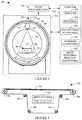
- FIG. 2schematically illustrates an example imaging inspection system 200 .
- the illustrated imaging inspection system 200is configured to scan an object 202 (e.g., luggage, baggage, etc.) and items 203 therein, and detect contraband items, such as explosives, and/or other prohibited items of the items 203 .
- the imaging inspection system 200in one instance, is an aviation security and/or inspection computed tomography (CT) based imaging inspection system at an airport checkpoint and/or other location. In another instance, the imaging inspection system 200 is configured for non-destructive testing, medical, and/or other imaging.
- CTcomputed tomography
- the illustrated imaging inspection system 200includes a stationary frame 204 with an aperture 206 and a rotating frame 208 .
- the rotating frame 208is rotatably supported in the aperture via a bearing 210 , which includes a first portion 212 affixed to the stationary frame 204 and a second portion 214 affixed to the rotating frame 208 .
- the rotating frame 208rotates about an examination region 216 .
- the rotating frame 208supports a radiation source(s) 218 (e.g., an ionizing X-ray source, etc.) and a detector array 220 , which is disposed diametrically opposite the radiation source(s) 218 , across the examination region 216 .
- a conveyor assembly 222supports the object 202 in the examination region 216 , including moving the object through the examination region 216 .
- the conveyor assembly 222includes a continuous belt 302 supported by two opposing pulleys 304 and four idler pulleys 306 .
- the conveyor assembly 222further includes a drive system(s) 308 , which include at least a controller 310 , which controls a motor 312 to drive an actuator 314 (e.g., a belt, a gear, a ball screw, a lead screw, etc.) to rotate one or more of the pulleys 304 and/or 306 to translate the belt 302 .
- a suitable conveyor assembly 22is described in U.S. Pat. No. 7,072,434, filed Jan. 15, 2044, and entitled “Carry-on baggage tomography scanning system,” the entirety of which is incorporated herein by reference.
- the radiation source(s) 218emits radiation, which is collimated, e.g., via a collimator 224 , to produce a fan, cone, wedge, and/or other shaped radiation beam 226 , which traverses the examination region 216 , including the object 202 and items 203 , which attenuate or absorb radiation based on, e.g., a material composition and/or density of the object 202 and items 203 .
- the detector array 220includes a 1-D or 2-D array of detectors, which detect the radiation and generates an electrical signal(s) (projection data) indicative of an attenuation by the object 202 and items 203 .
- An image reconstructor 228reconstructs the electrical signal(s), generating volumetric image data indicative of the object 202 and the items 203 .
- a computer 230is configured to provide a signal(s) that controls components such as the rotating frame 208 , the radiation source 218 , the detector array 220 and the conveyor assembly 222 for scanning, the image reconstructor 228 for generating the volumetric image data, and to receive the volumetric image data from the image reconstructor 228 and process and display the volumetric image data via a display monitor(s) 232 , which can be part of and/or in electrical communication with the computer 230 .
- the computer 230is also configured with an input device(s) to receive user input, which controls an operation(s) such as a speed of gantry rotation, kVp, mA, etc.
- the computer 230includes a processor 234 (e.g., a microprocessor, a central processing unit, a controller, etc.) and a user interface algorithm(s) 236 .
- the processor 230executes the user interface algorithm(s) 236 and generates a user interface(s), which is displayed with the display monitor(s) 232 .
- the user interfaceis a graphical user interface (GUI) with a single view port to display a 3-D image.
- the GUIincludes two view ports for concurrent and/or simultaneous display of two different 3-D images.
- the GUIincludes N (N>2) view ports to display N images, one in each view port.
- the computer 230further includes a visualization or rendering algorithm(s) 238 .
- the rendering algorithm(s) 238includes at least two different algorithms for generating at least two different 3-D images of the object 202 and the items 203 emphasizing different characteristics (e.g., material composition, surface, etc.) of the object 202 and the items 203 , and the processor 234 concurrently and/or simultaneously displays the at least two different 3-D images in different view ports of the display monitor(s) 232 .
- concurrent and/or simultaneous display of the at least two 3-D imagesallow a user to more quickly and accurately identify the items 203 , relative to a configuration in which only a single rendering algorithm 238 is utilized, e.g., by showing a more complete representation of identify the items, simultaneously, which, in one instance, can speed up and/or improve the inspection process, e.g., for clearing threats.
- the computer 230further includes an image processing detection algorithm(s) 240 .
- the processor 234executes the image processing detection algorithm(s) 240 to process the volumetric image data and identify contraband in the object 202 therefrom.
- detection algorithmsinclude, but are not limited to, U.S. Pat. No. 7,190,757 B2, filed May 21, 2004, and entitled “Method of and system for computing effective atomic number images in multi-energy computed tomography,” U.S. Pat. No. 7,302,083 B2, filed Jul. 1, 2004, and entitled “Method of and system for sharp object detection using computed tomography images,” and U.S. Pat. No. 8,787,669 B2, filed Sep. 30, 2008, and entitled “Compound object separation,” all of which are incorporated herein by reference in their entireties.
- example component diagramis merely intended to illustrate an embodiment of a type of imaging modality and is not intended to be interpreted in a limiting manner.
- the functions of one or more components described hereinmay be separated into a plurality of components and/or the functions of two or more components described herein may be consolidated into merely a single component.
- the imaging modalitymay comprise additional components to perform additional features, functions, etc.
- FIG. 4illustrates an example in which the displays 232 include a single display 402 .
- the user interface algorithm(s) 236includes at least an algorithm 410 for generating a single GUI 404 , with at least two view ports 406 1 , . . . , 406 N (where N is an integer equal to or greater than two), rendered in the single display 402 .
- Each at least two view ports 406 1 , . . . , 406 Ndisplays a 3-D image, 408 1 , . . . , 408 N .
- Each 3-D image 408 1 , . . . , 408 Nis displayed from a vantage point of a view plane through the 3-D image and into a remaining depth of the 3-D image, wherein the portion of the 3-D image in front of the view plane is either rendering transparent or not at all.
- the rendering algorithm(s) 238includes at least a first algorithm 412 1 for a generating semi-transparent 3-D rendering and an m-th algorithm 412 N for generating a surface 3-D rendering.
- a suitable semi-transparent renderinguses transparency and/or colors to represent the object 202 as a semi-transparent volume. For example, the outside of the object 202 and/or one or more of the items 203 is displayed as semi-transparent so that it does not visually conceal other items 203 there behind.
- a suitable surface rendering algorithmuses a threshold value of radiodensity (to see through the outer cloth but detect items of interest inside) and edge detection to detect surfaces of the items 203 in the object 202 , where only the surface closest to the user (the view plane) is visible.
- having at least shape recognition from the surface rendering and the semi-transparent renderingcan speed up the process for clearing threats since each rendering visually displays the items 203 of the object 202 differently.
- the semi-transparent renderingcan facilitate quick identification of an item as an item of interest and the surface rendering can facilitate identifying what these items are.
- the multiple renderings in the view ports 406 1 , . . . , 406 Ncan be manipulated independently or synchronously to a single user action for operations such as zoom, rotate, pan, contrast, brightness, opacity and/or other operation. Manipulating both in synchronization may reduce user interaction and optimize workflow. The manipulation can be performed via a mouse, keyboard, and/or touchscreen, e.g., using both single and multi-touch gestures.
- FIG. 5illustrates a variation in which the displays 232 includes at least two displays 502 1 , . . . , 502 N , and the user interface algorithm(s) 236 includes at least two algorithms 410 1 , . . . , 410 N , for generating at least two GUIs 504 and 506 , one in each of the displays 502 1 , . . . , 502 N , and each respectively visually presenting at least one view port 508 and 510 , each respectively displaying a 3-D image 512 and 514 generated with different algorithms of the rendering algorithm(s) 238 .
- the user interface algorithm(s) 236includes at least two algorithms 410 1 , . . . , 410 N , for generating at least two GUIs 504 and 506 , one in each of the displays 502 1 , . . . , 502 N , and each respectively visually presenting at least one view port 508 and 510 , each respectively displaying a 3-
- FIGS. 4 and 5are combined, e.g., for an embodiment which includes more than one display 232 , where at least one of the displays 232 visually presents a GUI with multiple view ports that display views of volumetric image data processed using different rendering algorithms of the rendering algorithms 238 .
- all of the displays 232include multiple view ports.
- at least one of the displaysincludes only a single view port.
- FIG. 6shows the single GUI 404 with the two view ports 406 1 , . . . , 406 N .
- the view port 406 1presents the 3-D image 408 1 generated with the semi-transparent algorithm 412 1
- the view port 406 Npresents the 3-D image 408 N generated with the surface algorithm 412 N
- each of the algorithms 412 1 , . . . , 412 Nincludes a color lookup table (LUT) that maps each voxel in the volumetric image data to a specific color in the Hue/Saturation/Value (HSV) color model and/or gray value, e.g., in a gray scale range, and an opacity table that maps each voxel to a specific transparency.
- the LUT and/or opacityis different for each algorithm 412 1 , . . . , 412 N .
- One or both of the algorithms 412 1 , . . . , 412 Nalso provide shading.
- the items 203include at least a pair of scissors 602 and a container 604 filled with a fluid, where the simultaneous observation makes it easier to locate the pair of scissors 602 and container 604 .
- the 3-D image 408 1makes it easier to locate metallic items such as the pair of scissors 602 and containers holding fluids, at least since different material compositions are different colored and items behind items are visible, but not necessarily identify what those items 203 are, and the 3-D image 408 N makes it easier to identify what those items 203 are—a pair of scissors and a container—but not with discerning those particular items within all of the other items 203 at least since all of the surface are similarly represented in gray scale.
- the semi-transparent algorithm 412 1provides a traditional rendering for security imaging where materials are shown using standard industry defined colors with standard industry defined transparency levels that allows a user to see through or inside the object 202 and/or the items 203 therein, which may facilitate finding concealed items.
- outer cloth of the object 202is shown virtually completely transparent
- the container 604is shown semi-transparent and with one color where an item 606 can be seen there through
- the pair of scissors 602is shown virtually non-transparent and with a different color, since the material composition (e.g., metal vs plastic) of the container and the scissors is different.
- the transparency levelin general, corresponds to the material composition, and can vary across the items 203 , with items less likely to be contraband rendered more transparent.
- FIG. 13An example opacity mapping 1300 for the semi-transparent algorithm 412 1 is shown in FIG. 13 , where a first axis 1302 represents opacity and a second axis 1304 represents CT number (e.g., in Hounsfield units).
- the surface algorithm 412 Ninstead utilizes a different LUT and a different opacity table, (e.g., with lower transparency levels, e.g., opaque) for showing surfaces of the items 203 , which will more closely visually match a physical outer appearance of the items 203 .
- the outer cloth of the object 202is likewise shown virtually completely transparent, e.g., due to thresholding.
- the surface of the container 604is shown opaque such that the inside of the container 604 is not visible and neither is the item 606 behind the container 604 .
- the surface of the pair of scissors 602is shown opaque such items there behind are not visible.
- the items 203are all shown using gray scale levels with shading representing depth.
- An example surface rendering algorithmis ray casting, which locates a ray-surface intersection in the volumetric data.
- An example opacity mapping 1400 for the surface algorithm 412 Nis shown in FIG. 14 , where a first axis 1402 represents opacity and a second axis 1404 represents CT number (e.g., in Hounsfield units).
- FIG. 7shows another example with the GUI 404 with the two view ports 406 1 , . . . , 406 N .
- the items 203include at least a knife 702 , where the simultaneous observation makes it easier to locate and identify the knife 702 .
- the 3-D image 408 1makes it easier to locate a metallic item such as the knife 702 , but not clearly identify what that metallic item is at least since parts of it are almost completely transparent and other parts of it are concealed by combined with other items
- the 3-D image 408 Nmakes it easier to identify what the metallic item is—the knife 702 at least since the blade is more apparent, but not clearly locate the item at least since it is mostly visually obstructed by another item 704 in front of it.
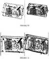
- FIGS. 8 and 9show another a GUI with the two view ports.
- the GUIis configured so that at least a rotation tool synchronously rotates the 3-D images in both view ports such that rotating (e.g., via a mouse, keyboard, touchscreen, etc.) the volumetric image data in either of the view ports automatically causes the volumetric image data in the other view port to similarly rotate.
- FIGS. 10 and 11show another a GUI with the two view ports.
- the GUIis configured so that at least a zoom tool synchronously zooms the 3-D images in both view ports such that zooming (e.g., via a mouse, keyboard, touchscreen, etc.) the volumetric image data in either of the view ports automatically causes the volumetric image data in the other view port to similarly zoom.
- a screen layoutprovides for a dual 3-D image display of volumetric image data side-by-side on screen, where one displayed 3-D volume provides a semi-transparent rendering for seeing inside and through objects, and the other displayed 3-D volume provides a surface rendering for seeing shapes and contours of items 203 inside the object 202 .
- the semi-transparent imageprovides the operator with the sense of layers, which can be added or removed through adjustment in opacity, whereas the surface rendered display gives the operator information of the surface structure.
- FIG. 12illustrates an example method.
- an objectis scanned with the imaging inspection system 200 , producing view data.
- the view datais reconstructed, producing volumetric image data of the object.
- the volumetric image datais processed with detection software for computerized detection of contraband in the items 203 .
- a first visualization algorithmis applied to the volumetric image data, producing first processed volumetric image data, as described herein and/or otherwise.
- a second different visualization algorithmis applied to the volumetric image data, producing second different processed volumetric image data, as described herein and/or otherwise.
- the first and the second volumetric image dataare concurrently displayed, as described herein and/or otherwise.
- the methods described hereinmay be implemented via one or more processors executing one or more computer readable instructions encoded or embodied on computer-readable storage medium which causes the one or more processors to carry out the various acts and/or other functions and/or acts. Additionally or alternatively, the one or more processors can execute instructions carried by transitory medium such as a signal or carrier wave.
Landscapes
- Physics & Mathematics (AREA)
- Engineering & Computer Science (AREA)
- General Physics & Mathematics (AREA)
- Theoretical Computer Science (AREA)
- Computer Graphics (AREA)
- Computer Hardware Design (AREA)
- General Engineering & Computer Science (AREA)
- Software Systems (AREA)
- High Energy & Nuclear Physics (AREA)
- Geophysics (AREA)
- General Life Sciences & Earth Sciences (AREA)
- Life Sciences & Earth Sciences (AREA)
- Health & Medical Sciences (AREA)
- Radiology & Medical Imaging (AREA)
- Nuclear Medicine, Radiotherapy & Molecular Imaging (AREA)
- General Health & Medical Sciences (AREA)
- Analysing Materials By The Use Of Radiation (AREA)
- Computer Vision & Pattern Recognition (AREA)
Abstract
Description
Claims (20)
Priority Applications (1)
| Application Number | Priority Date | Filing Date | Title |
|---|---|---|---|
| US15/496,162US10782441B2 (en) | 2017-04-25 | 2017-04-25 | Multiple three-dimensional (3-D) inspection renderings |
Applications Claiming Priority (1)
| Application Number | Priority Date | Filing Date | Title |
|---|---|---|---|
| US15/496,162US10782441B2 (en) | 2017-04-25 | 2017-04-25 | Multiple three-dimensional (3-D) inspection renderings |
Publications (2)
| Publication Number | Publication Date |
|---|---|
| US20180308255A1 US20180308255A1 (en) | 2018-10-25 |
| US10782441B2true US10782441B2 (en) | 2020-09-22 |
Family
ID=63854565
Family Applications (1)
| Application Number | Title | Priority Date | Filing Date |
|---|---|---|---|
| US15/496,162ActiveUS10782441B2 (en) | 2017-04-25 | 2017-04-25 | Multiple three-dimensional (3-D) inspection renderings |
Country Status (1)
| Country | Link |
|---|---|
| US (1) | US10782441B2 (en) |
Families Citing this family (2)
| Publication number | Priority date | Publication date | Assignee | Title |
|---|---|---|---|---|
| JP7239507B2 (en)* | 2020-01-30 | 2023-03-14 | 株式会社日立製作所 | ALERT OUTPUT TIMING CONTROL DEVICE, ALERT OUTPUT TIMING CONTROL METHOD, ALERT OUTPUT TIMING CONTROL PROGRAM |
| CN116958646B (en)* | 2023-06-12 | 2024-01-30 | 北京声迅电子股份有限公司 | Forbidden article detection method based on X-ray image |
Citations (29)
| Publication number | Priority date | Publication date | Assignee | Title |
|---|---|---|---|---|
| US20020109684A1 (en)* | 2000-12-18 | 2002-08-15 | Repin Dmitriy G. | Method and apparatus for visualization of 3D voxel data using lit opacity volumes with shading |
| US20030095630A1 (en)* | 2001-11-20 | 2003-05-22 | Avinash Gopal B. | Contrast adjustment of a decomposed X-ray image relative to the contrast of another X-ray image |
| US20040062346A1 (en)* | 2002-08-30 | 2004-04-01 | Fernandez Kenneth R. | Article screening system |
| US20050276443A1 (en)* | 2004-05-28 | 2005-12-15 | Slamani Mohamed A | Method and apparatus for recognizing an object within an image |
| US20060008140A1 (en)* | 2004-07-09 | 2006-01-12 | Dainippon Screen Mfg. Co., Ltd. | Segmentation technique of a color image according to colors |
| US20060104414A1 (en)* | 2002-01-30 | 2006-05-18 | Mayo William E | Combinatorial contraband detection using energy dispersive x-ray diffraction |
| US7072434B1 (en) | 2003-01-16 | 2006-07-04 | Analogic Corporation | Carry-on baggage tomography scanning system |
| US7190757B2 (en) | 2004-05-21 | 2007-03-13 | Analogic Corporation | Method of and system for computing effective atomic number images in multi-energy computed tomography |
| US20070168467A1 (en)* | 2006-01-15 | 2007-07-19 | Telesecurity Sciences Inc. | Method and system for providing remote access to baggage scanned images |
| US20070247647A1 (en)* | 2006-04-21 | 2007-10-25 | Daniel Pettigrew | 3D lut techniques for color correcting images |
| US7302083B2 (en) | 2004-07-01 | 2007-11-27 | Analogic Corporation | Method of and system for sharp object detection using computed tomography images |
| US20080151047A1 (en)* | 2006-12-20 | 2008-06-26 | General Electric Company | Inspection apparatus method and apparatus comprising selective frame output |
| US20080170660A1 (en)* | 2006-05-11 | 2008-07-17 | Dan Gudmundson | Method and apparatus for providing threat image projection (tip) in a luggage screening system, and luggage screening system implementing same |
| US20090034790A1 (en)* | 2007-08-01 | 2009-02-05 | Telesecurity Sciences, Inc. | Method for customs inspection of baggage and cargo |
| US20090174729A1 (en)* | 2008-01-09 | 2009-07-09 | Ziosoft, Inc. | Image display device and control method thereof |
| US20090238335A1 (en)* | 2008-03-06 | 2009-09-24 | L-3 Communications Security and Detection Systems Corporation | Suitcase compartmentalized for security inspection and system |
| US20100046704A1 (en)* | 2008-08-25 | 2010-02-25 | Telesecurity Sciences, Inc. | Method and system for electronic inspection of baggage and cargo |
| US20100215144A1 (en)* | 2009-02-26 | 2010-08-26 | Samit Kumar Basu | Method and system for performing a scan of an object |
| US20100235112A1 (en)* | 2009-03-12 | 2010-09-16 | Sheet Dynamics Ltd. | Managing non-destructive evaluation data |
| US20100235111A1 (en)* | 2009-03-12 | 2010-09-16 | Sheet Dynamics Ltd. | Managing non-destructive evaluation data |
| US20110085718A1 (en)* | 2009-10-13 | 2011-04-14 | Eugene Alex Ingerman | Methods and system for selective resolution improvement in computed tomography |
| US20110222647A1 (en)* | 2010-03-15 | 2011-09-15 | Omron Corporation | X-ray inspection apparatus and x-ray inspection method |
| US20110227910A1 (en)* | 2008-03-27 | 2011-09-22 | Analogic Corporation | Method of and system for three-dimensional workstation for security and medical applications |
| US20140133718A1 (en)* | 2012-11-14 | 2014-05-15 | Varian Medical Systems, Inc. | Method and Apparatus Pertaining to Identifying Objects of Interest in a High-Energy Image |
| US8787669B2 (en) | 2008-09-30 | 2014-07-22 | Analogic Corporation | Compound object separation |
| US20150022522A1 (en)* | 2012-03-20 | 2015-01-22 | Siemens Corporation | Luggage Visualization and Virtual Unpacking |
| US20150248197A1 (en)* | 2012-10-01 | 2015-09-03 | Koninklijke Philips N.V. | Visualizing image data |
| US20160005218A1 (en)* | 2014-07-01 | 2016-01-07 | Kabushiki Kaisha Toshiba | Image rendering apparatus and method |
| US20180130236A1 (en)* | 2016-11-07 | 2018-05-10 | Uih America, Inc. | Image reconstruction system and method in magnetic resonance imaging |
- 2017
- 2017-04-25USUS15/496,162patent/US10782441B2/enactiveActive
Patent Citations (29)
| Publication number | Priority date | Publication date | Assignee | Title |
|---|---|---|---|---|
| US20020109684A1 (en)* | 2000-12-18 | 2002-08-15 | Repin Dmitriy G. | Method and apparatus for visualization of 3D voxel data using lit opacity volumes with shading |
| US20030095630A1 (en)* | 2001-11-20 | 2003-05-22 | Avinash Gopal B. | Contrast adjustment of a decomposed X-ray image relative to the contrast of another X-ray image |
| US20060104414A1 (en)* | 2002-01-30 | 2006-05-18 | Mayo William E | Combinatorial contraband detection using energy dispersive x-ray diffraction |
| US20040062346A1 (en)* | 2002-08-30 | 2004-04-01 | Fernandez Kenneth R. | Article screening system |
| US7072434B1 (en) | 2003-01-16 | 2006-07-04 | Analogic Corporation | Carry-on baggage tomography scanning system |
| US7190757B2 (en) | 2004-05-21 | 2007-03-13 | Analogic Corporation | Method of and system for computing effective atomic number images in multi-energy computed tomography |
| US20050276443A1 (en)* | 2004-05-28 | 2005-12-15 | Slamani Mohamed A | Method and apparatus for recognizing an object within an image |
| US7302083B2 (en) | 2004-07-01 | 2007-11-27 | Analogic Corporation | Method of and system for sharp object detection using computed tomography images |
| US20060008140A1 (en)* | 2004-07-09 | 2006-01-12 | Dainippon Screen Mfg. Co., Ltd. | Segmentation technique of a color image according to colors |
| US20070168467A1 (en)* | 2006-01-15 | 2007-07-19 | Telesecurity Sciences Inc. | Method and system for providing remote access to baggage scanned images |
| US20070247647A1 (en)* | 2006-04-21 | 2007-10-25 | Daniel Pettigrew | 3D lut techniques for color correcting images |
| US20080170660A1 (en)* | 2006-05-11 | 2008-07-17 | Dan Gudmundson | Method and apparatus for providing threat image projection (tip) in a luggage screening system, and luggage screening system implementing same |
| US20080151047A1 (en)* | 2006-12-20 | 2008-06-26 | General Electric Company | Inspection apparatus method and apparatus comprising selective frame output |
| US20090034790A1 (en)* | 2007-08-01 | 2009-02-05 | Telesecurity Sciences, Inc. | Method for customs inspection of baggage and cargo |
| US20090174729A1 (en)* | 2008-01-09 | 2009-07-09 | Ziosoft, Inc. | Image display device and control method thereof |
| US20090238335A1 (en)* | 2008-03-06 | 2009-09-24 | L-3 Communications Security and Detection Systems Corporation | Suitcase compartmentalized for security inspection and system |
| US20110227910A1 (en)* | 2008-03-27 | 2011-09-22 | Analogic Corporation | Method of and system for three-dimensional workstation for security and medical applications |
| US20100046704A1 (en)* | 2008-08-25 | 2010-02-25 | Telesecurity Sciences, Inc. | Method and system for electronic inspection of baggage and cargo |
| US8787669B2 (en) | 2008-09-30 | 2014-07-22 | Analogic Corporation | Compound object separation |
| US20100215144A1 (en)* | 2009-02-26 | 2010-08-26 | Samit Kumar Basu | Method and system for performing a scan of an object |
| US20100235112A1 (en)* | 2009-03-12 | 2010-09-16 | Sheet Dynamics Ltd. | Managing non-destructive evaluation data |
| US20100235111A1 (en)* | 2009-03-12 | 2010-09-16 | Sheet Dynamics Ltd. | Managing non-destructive evaluation data |
| US20110085718A1 (en)* | 2009-10-13 | 2011-04-14 | Eugene Alex Ingerman | Methods and system for selective resolution improvement in computed tomography |
| US20110222647A1 (en)* | 2010-03-15 | 2011-09-15 | Omron Corporation | X-ray inspection apparatus and x-ray inspection method |
| US20150022522A1 (en)* | 2012-03-20 | 2015-01-22 | Siemens Corporation | Luggage Visualization and Virtual Unpacking |
| US20150248197A1 (en)* | 2012-10-01 | 2015-09-03 | Koninklijke Philips N.V. | Visualizing image data |
| US20140133718A1 (en)* | 2012-11-14 | 2014-05-15 | Varian Medical Systems, Inc. | Method and Apparatus Pertaining to Identifying Objects of Interest in a High-Energy Image |
| US20160005218A1 (en)* | 2014-07-01 | 2016-01-07 | Kabushiki Kaisha Toshiba | Image rendering apparatus and method |
| US20180130236A1 (en)* | 2016-11-07 | 2018-05-10 | Uih America, Inc. | Image reconstruction system and method in magnetic resonance imaging |
Also Published As
| Publication number | Publication date |
|---|---|
| US20180308255A1 (en) | 2018-10-25 |
Similar Documents
| Publication | Publication Date | Title |
|---|---|---|
| US20110227910A1 (en) | Method of and system for three-dimensional workstation for security and medical applications | |
| CN105785462B (en) | A method and security inspection CT system for locating a target in a three-dimensional CT image | |
| US8457273B2 (en) | Generating a representation of an object of interest | |
| EP2443441B1 (en) | Method and apparatus for assessing the threat status of luggage | |
| US9053565B2 (en) | Interactive selection of a region of interest in an image | |
| CN104508710B (en) | The vision of selectivity tissue in view data is suppressed | |
| JP6968826B2 (en) | Systems and methods for generating projected images | |
| US8254656B2 (en) | Methods and system for selective resolution improvement in computed tomography | |
| EP3061073B1 (en) | Image visualization | |
| EP3257020B1 (en) | Three-dimensional object image generation | |
| US11594001B2 (en) | Methods and systems for generating three-dimensional images that enable improved visualization and interaction with objects in the three-dimensional images | |
| EP3290912A1 (en) | Examination system for inspection and quarantine and method thereof | |
| CN106716496B (en) | Visualizing a volumetric image of an anatomical structure | |
| JP2020044341A (en) | Reconstructed image data visualization | |
| US10782441B2 (en) | Multiple three-dimensional (3-D) inspection renderings | |
| CN112598682B (en) | Three-dimensional CT image sectioning method and device based on any angle | |
| CN112288888A (en) | A method and device for marking objects in a three-dimensional CT image | |
| EP2828826B1 (en) | Extracting bullous emphysema and diffuse emphysema in e.g. ct volume images of the lungs | |
| US20230334732A1 (en) | Image rendering method for tomographic image data | |
| Chatzigiannis | 3D Volume Data in Nuclear Medicine | |
| Chatzigiannis | 6 3D Volume Data | |
| CN112907670A (en) | Target object positioning and labeling method and device based on profile | |
| HK1195820B (en) | 3-dimensional model creation methods and apparatuses | |
| HK1195943A (en) | Methods for detecting objects, display methods and apparatuses | |
| HK1195943B (en) | Methods for detecting objects, display methods and apparatuses |
Legal Events
| Date | Code | Title | Description |
|---|---|---|---|
| AS | Assignment | Owner name:ANALOGIC CORPORATION, MASSACHUSETTS Free format text:ASSIGNMENT OF ASSIGNORS INTEREST;ASSIGNORS:BRENNAN, KEVIN;DAVIDSON, WILLIAM;SPLINTER, PATRICK;REEL/FRAME:042135/0027 Effective date:20170419 | |
| AS | Assignment | Owner name:MIDCAP FINANCIAL TRUST, MARYLAND Free format text:SECURITY INTEREST;ASSIGNORS:ANALOGIC CORPORATION;SOUND TECHNOLOGY, INC.;REEL/FRAME:046414/0277 Effective date:20180622 | |
| STPP | Information on status: patent application and granting procedure in general | Free format text:ADVISORY ACTION MAILED | |
| STPP | Information on status: patent application and granting procedure in general | Free format text:DOCKETED NEW CASE - READY FOR EXAMINATION | |
| STPP | Information on status: patent application and granting procedure in general | Free format text:NON FINAL ACTION MAILED | |
| STPP | Information on status: patent application and granting procedure in general | Free format text:NON FINAL ACTION MAILED | |
| STPP | Information on status: patent application and granting procedure in general | Free format text:RESPONSE TO NON-FINAL OFFICE ACTION ENTERED AND FORWARDED TO EXAMINER | |
| STPP | Information on status: patent application and granting procedure in general | Free format text:FINAL REJECTION MAILED | |
| STPP | Information on status: patent application and granting procedure in general | Free format text:DOCKETED NEW CASE - READY FOR EXAMINATION | |
| STPP | Information on status: patent application and granting procedure in general | Free format text:NOTICE OF ALLOWANCE MAILED -- APPLICATION RECEIVED IN OFFICE OF PUBLICATIONS | |
| STPP | Information on status: patent application and granting procedure in general | Free format text:PUBLICATIONS -- ISSUE FEE PAYMENT VERIFIED | |
| STCF | Information on status: patent grant | Free format text:PATENTED CASE | |
| AS | Assignment | Owner name:ANALOGIC CORPORATION, MASSACHUSETTS Free format text:RELEASE BY SECURED PARTY;ASSIGNOR:MIDCAP FINANCIAL TRUST;REEL/FRAME:064917/0544 Effective date:20230914 | |
| AS | Assignment | Owner name:TRUIST BANK, AS COLLATERAL AGENT, GEORGIA Free format text:SECURITY INTEREST;ASSIGNOR:ANALOGIC CORPORATION;REEL/FRAME:064954/0027 Effective date:20230914 | |
| MAFP | Maintenance fee payment | Free format text:PAYMENT OF MAINTENANCE FEE, 4TH YEAR, LARGE ENTITY (ORIGINAL EVENT CODE: M1551); ENTITY STATUS OF PATENT OWNER: LARGE ENTITY Year of fee payment:4 |