US10779971B2 - Endovascular implant - Google Patents
Endovascular implantDownload PDFInfo
- Publication number
- US10779971B2 US10779971B2US15/640,095US201715640095AUS10779971B2US 10779971 B2US10779971 B2US 10779971B2US 201715640095 AUS201715640095 AUS 201715640095AUS 10779971 B2US10779971 B2US 10779971B2
- Authority
- US
- United States
- Prior art keywords
- tack
- expanding tubular
- plaque
- catheter
- self
- Prior art date
- Legal status (The legal status is an assumption and is not a legal conclusion. Google has not performed a legal analysis and makes no representation as to the accuracy of the status listed.)
- Active, expires
Links
- 239000007943implantSubstances0.000titledescription4
- 210000001367arteryAnatomy0.000claimsdescription59
- 238000000034methodMethods0.000claimsdescription46
- 230000033001locomotionEffects0.000claimsdescription26
- 230000004323axial lengthEffects0.000claimsdescription23
- 238000000418atomic force spectrumMethods0.000claimsdescription16
- 239000003550markerSubstances0.000claimsdescription12
- 210000003137popliteal arteryAnatomy0.000claimsdescription12
- 210000004204blood vesselAnatomy0.000abstractdescription133
- 230000003028elevating effectEffects0.000abstractdescription67
- 238000011282treatmentMethods0.000abstractdescription50
- 238000002399angioplastyMethods0.000abstractdescription37
- 239000000463materialSubstances0.000abstractdescription35
- 201000010099diseaseDiseases0.000abstractdescription10
- 208000037265diseases, disorders, signs and symptomsDiseases0.000abstractdescription10
- 230000003143atherosclerotic effectEffects0.000abstractdescription8
- 238000013459approachMethods0.000abstractdescription7
- 210000004027cellAnatomy0.000description66
- 238000013461designMethods0.000description34
- 229910052751metalInorganic materials0.000description28
- 239000002184metalSubstances0.000description28
- 238000002224dissectionMethods0.000description26
- 210000001519tissueAnatomy0.000description22
- 230000006835compressionEffects0.000description18
- 238000007906compressionMethods0.000description18
- 229940079593drugDrugs0.000description15
- 239000003814drugSubstances0.000description15
- 230000008901benefitEffects0.000description13
- 230000003902lesionEffects0.000description13
- 238000004519manufacturing processMethods0.000description12
- 230000009467reductionEffects0.000description11
- 230000002829reductive effectEffects0.000description11
- 230000000694effectsEffects0.000description10
- 208000037803restenosisDiseases0.000description10
- 230000002792vascularEffects0.000description10
- 208000031481Pathologic ConstrictionDiseases0.000description9
- 238000005452bendingMethods0.000description9
- 230000006378damageEffects0.000description9
- 208000037804stenosisDiseases0.000description9
- 230000008859changeEffects0.000description8
- 238000006243chemical reactionMethods0.000description8
- 230000000875corresponding effectEffects0.000description8
- 238000007667floatingMethods0.000description8
- 238000011068loading methodMethods0.000description8
- 230000014759maintenance of locationEffects0.000description8
- 230000004044responseEffects0.000description8
- 230000036262stenosisEffects0.000description8
- 206010061218InflammationDiseases0.000description7
- 230000001413cellular effectEffects0.000description7
- 239000003795chemical substances by applicationSubstances0.000description7
- 238000010276constructionMethods0.000description7
- 230000004054inflammatory processEffects0.000description7
- 230000008569processEffects0.000description7
- 230000009977dual effectEffects0.000description6
- 210000001105femoral arteryAnatomy0.000description6
- 230000003993interactionEffects0.000description6
- 230000000670limiting effectEffects0.000description6
- 230000007246mechanismEffects0.000description6
- 230000035515penetrationEffects0.000description6
- 230000000306recurrent effectEffects0.000description6
- 210000005166vasculatureAnatomy0.000description6
- 208000037260Atherosclerotic PlaqueDiseases0.000description5
- MWUXSHHQAYIFBG-UHFFFAOYSA-NNitric oxideChemical compoundO=[N]MWUXSHHQAYIFBG-UHFFFAOYSA-N0.000description5
- 239000013543active substanceSubstances0.000description5
- 230000017531blood circulationEffects0.000description5
- 230000004663cell proliferationEffects0.000description5
- 230000036755cellular responseEffects0.000description5
- 230000006870functionEffects0.000description5
- 238000011065in-situ storageMethods0.000description5
- 230000001965increasing effectEffects0.000description5
- 238000009434installationMethods0.000description5
- 239000003146anticoagulant agentSubstances0.000description4
- 230000006399behaviorEffects0.000description4
- 238000000576coating methodMethods0.000description4
- 239000002131composite materialSubstances0.000description4
- 239000003102growth factorSubstances0.000description4
- 206010020718hyperplasiaDiseases0.000description4
- 239000003112inhibitorSubstances0.000description4
- 208000014674injuryDiseases0.000description4
- 230000002093peripheral effectEffects0.000description4
- 208000027418Wounds and injuryDiseases0.000description3
- 230000001154acute effectEffects0.000description3
- 230000002411adverseEffects0.000description3
- 239000008280bloodSubstances0.000description3
- 239000011248coating agentSubstances0.000description3
- 238000005520cutting processMethods0.000description3
- 230000003247decreasing effectEffects0.000description3
- 238000009826distributionMethods0.000description3
- 230000002401inhibitory effectEffects0.000description3
- HLXZNVUGXRDIFK-UHFFFAOYSA-Nnickel titaniumChemical compound[Ti].[Ti].[Ti].[Ti].[Ti].[Ti].[Ti].[Ti].[Ti].[Ti].[Ti].[Ni].[Ni].[Ni].[Ni].[Ni].[Ni].[Ni].[Ni].[Ni].[Ni].[Ni].[Ni].[Ni].[Ni]HLXZNVUGXRDIFK-UHFFFAOYSA-N0.000description3
- 229910001000nickel titaniumInorganic materials0.000description3
- 229920000642polymerPolymers0.000description3
- 238000005381potential energyMethods0.000description3
- 238000012360testing methodMethods0.000description3
- IAKHMKGGTNLKSZ-INIZCTEOSA-N(S)-colchicineChemical compoundC1([C@@H](NC(C)=O)CC2)=CC(=O)C(OC)=CC=C1C1=C2C=C(OC)C(OC)=C1OCIAKHMKGGTNLKSZ-INIZCTEOSA-N0.000description2
- 101710112752CytotoxinProteins0.000description2
- AOJJSUZBOXZQNB-TZSSRYMLSA-NDoxorubicinChemical compoundO([C@H]1C[C@@](O)(CC=2C(O)=C3C(=O)C=4C=CC=C(C=4C(=O)C3=C(O)C=21)OC)C(=O)CO)[C@H]1C[C@H](N)[C@H](O)[C@H](C)O1AOJJSUZBOXZQNB-TZSSRYMLSA-N0.000description2
- 229940123011Growth factor receptor antagonistDrugs0.000description2
- HTTJABKRGRZYRN-UHFFFAOYSA-NHeparinChemical classOC1C(NC(=O)C)C(O)OC(COS(O)(=O)=O)C1OC1C(OS(O)(=O)=O)C(O)C(OC2C(C(OS(O)(=O)=O)C(OC3C(C(O)C(O)C(O3)C(O)=O)OS(O)(=O)=O)C(CO)O2)NS(O)(=O)=O)C(C(O)=O)O1HTTJABKRGRZYRN-UHFFFAOYSA-N0.000description2
- 238000005299abrasionMethods0.000description2
- 239000000654additiveSubstances0.000description2
- 230000000996additive effectEffects0.000description2
- 210000003484anatomyAnatomy0.000description2
- 238000004873anchoringMethods0.000description2
- 230000003466anti-cipated effectEffects0.000description2
- 230000000702anti-platelet effectEffects0.000description2
- 230000001028anti-proliverative effectEffects0.000description2
- 239000004019antithrombinChemical class0.000description2
- 230000001588bifunctional effectEffects0.000description2
- HVYWMOMLDIMFJA-DPAQBDIFSA-NcholesterolChemical compoundC1C=C2C[C@@H](O)CC[C@]2(C)[C@@H]2[C@@H]1[C@@H]1CC[C@H]([C@H](C)CCCC(C)C)[C@@]1(C)CC2HVYWMOMLDIMFJA-DPAQBDIFSA-N0.000description2
- 238000003776cleavage reactionMethods0.000description2
- 150000001875compoundsChemical class0.000description2
- 230000001276controlling effectEffects0.000description2
- 230000002596correlated effectEffects0.000description2
- 230000007797corrosionEffects0.000description2
- 238000005260corrosionMethods0.000description2
- 238000002788crimpingMethods0.000description2
- 231100000599cytotoxic agentToxicity0.000description2
- 239000002619cytotoxinSubstances0.000description2
- 230000007423decreaseEffects0.000description2
- 238000011161developmentMethods0.000description2
- 230000018109developmental processEffects0.000description2
- 238000010586diagramMethods0.000description2
- 230000000916dilatatory effectEffects0.000description2
- 230000003292diminished effectEffects0.000description2
- 230000035876healingEffects0.000description2
- 238000010438heat treatmentMethods0.000description2
- 238000002513implantationMethods0.000description2
- 230000006872improvementEffects0.000description2
- 238000003780insertionMethods0.000description2
- 230000037431insertionEffects0.000description2
- 230000001788irregularEffects0.000description2
- 230000007774longtermEffects0.000description2
- 230000004048modificationEffects0.000description2
- 238000012986modificationMethods0.000description2
- 230000036961partial effectEffects0.000description2
- 230000007406plaque accumulationEffects0.000description2
- BASFCYQUMIYNBI-UHFFFAOYSA-NplatinumChemical compound[Pt]BASFCYQUMIYNBI-UHFFFAOYSA-N0.000description2
- 230000007017scissionEffects0.000description2
- 239000012781shape memory materialSubstances0.000description2
- 210000000329smooth muscle myocyteAnatomy0.000description2
- 239000010935stainless steelSubstances0.000description2
- 229910001220stainless steelInorganic materials0.000description2
- 229910052715tantalumInorganic materials0.000description2
- GUVRBAGPIYLISA-UHFFFAOYSA-Ntantalum atomChemical compound[Ta]GUVRBAGPIYLISA-UHFFFAOYSA-N0.000description2
- 210000005167vascular cellAnatomy0.000description2
- 208000019553vascular diseaseDiseases0.000description2
- KWPACVJPAFGBEQ-IKGGRYGDSA-N(2s)-1-[(2r)-2-amino-3-phenylpropanoyl]-n-[(3s)-1-chloro-6-(diaminomethylideneamino)-2-oxohexan-3-yl]pyrrolidine-2-carboxamideChemical compoundC([C@@H](N)C(=O)N1[C@@H](CCC1)C(=O)N[C@@H](CCCNC(N)=N)C(=O)CCl)C1=CC=CC=C1KWPACVJPAFGBEQ-IKGGRYGDSA-N0.000description1
- PUDHBTGHUJUUFI-SCTWWAJVSA-N(4r,7s,10s,13r,16s,19r)-10-(4-aminobutyl)-n-[(2s,3r)-1-amino-3-hydroxy-1-oxobutan-2-yl]-19-[[(2r)-2-amino-3-naphthalen-2-ylpropanoyl]amino]-16-[(4-hydroxyphenyl)methyl]-13-(1h-indol-3-ylmethyl)-6,9,12,15,18-pentaoxo-7-propan-2-yl-1,2-dithia-5,8,11,14,17-pChemical compoundC([C@H]1C(=O)N[C@H](CC=2C3=CC=CC=C3NC=2)C(=O)N[C@@H](CCCCN)C(=O)N[C@H](C(N[C@@H](CSSC[C@@H](C(=O)N1)NC(=O)[C@H](N)CC=1C=C2C=CC=CC2=CC=1)C(=O)N[C@@H]([C@@H](C)O)C(N)=O)=O)C(C)C)C1=CC=C(O)C=C1PUDHBTGHUJUUFI-SCTWWAJVSA-N0.000description1
- ZKMNUMMKYBVTFN-HNNXBMFYSA-N(S)-ropivacaineChemical compoundCCCN1CCCC[C@H]1C(=O)NC1=C(C)C=CC=C1CZKMNUMMKYBVTFN-HNNXBMFYSA-N0.000description1
- LEBVLXFERQHONN-UHFFFAOYSA-N1-butyl-N-(2,6-dimethylphenyl)piperidine-2-carboxamideChemical compoundCCCCN1CCCCC1C(=O)NC1=C(C)C=CC=C1CLEBVLXFERQHONN-UHFFFAOYSA-N0.000description1
- SGTNSNPWRIOYBX-UHFFFAOYSA-N2-(3,4-dimethoxyphenyl)-5-{[2-(3,4-dimethoxyphenyl)ethyl](methyl)amino}-2-(propan-2-yl)pentanenitrileChemical compoundC1=C(OC)C(OC)=CC=C1CCN(C)CCCC(C#N)(C(C)C)C1=CC=C(OC)C(OC)=C1SGTNSNPWRIOYBX-UHFFFAOYSA-N0.000description1
- BSYNRYMUTXBXSQ-FOQJRBATSA-N59096-14-9Chemical compoundCC(=O)OC1=CC=CC=C1[14C](O)=OBSYNRYMUTXBXSQ-FOQJRBATSA-N0.000description1
- STQGQHZAVUOBTE-UHFFFAOYSA-N7-Cyan-hept-2t-en-4,6-diinsaeureNatural productsC1=2C(O)=C3C(=O)C=4C(OC)=CC=CC=4C(=O)C3=C(O)C=2CC(O)(C(C)=O)CC1OC1CC(N)C(O)C(C)O1STQGQHZAVUOBTE-UHFFFAOYSA-N0.000description1
- 239000005541ACE inhibitorSubstances0.000description1
- 102400000068AngiostatinHuman genes0.000description1
- 108010079709AngiostatinsProteins0.000description1
- IYMAXBFPHPZYIK-BQBZGAKWSA-NArg-Gly-AspChemical compoundNC(N)=NCCC[C@H](N)C(=O)NCC(=O)N[C@@H](CC(O)=O)C(O)=OIYMAXBFPHPZYIK-BQBZGAKWSA-N0.000description1
- 206010003162Arterial injuryDiseases0.000description1
- BSYNRYMUTXBXSQ-UHFFFAOYSA-NAspirinChemical compoundCC(=O)OC1=CC=CC=C1C(O)=OBSYNRYMUTXBXSQ-UHFFFAOYSA-N0.000description1
- VOVIALXJUBGFJZ-KWVAZRHASA-NBudesonideChemical compoundC1CC2=CC(=O)C=C[C@]2(C)[C@@H]2[C@@H]1[C@@H]1C[C@H]3OC(CCC)O[C@@]3(C(=O)CO)[C@@]1(C)C[C@@H]2OVOVIALXJUBGFJZ-KWVAZRHASA-N0.000description1
- OYPRJOBELJOOCE-UHFFFAOYSA-NCalciumChemical compound[Ca]OYPRJOBELJOOCE-UHFFFAOYSA-N0.000description1
- 229930186147CephalosporinNatural products0.000description1
- OMFXVFTZEKFJBZ-UHFFFAOYSA-NCorticosteroneNatural productsO=C1CCC2(C)C3C(O)CC(C)(C(CC4)C(=O)CO)C4C3CCC2=C1OMFXVFTZEKFJBZ-UHFFFAOYSA-N0.000description1
- PMATZTZNYRCHOR-CGLBZJNRSA-NCyclosporin AChemical compoundCC[C@@H]1NC(=O)[C@H]([C@H](O)[C@H](C)C\C=C\C)N(C)C(=O)[C@H](C(C)C)N(C)C(=O)[C@H](CC(C)C)N(C)C(=O)[C@H](CC(C)C)N(C)C(=O)[C@@H](C)NC(=O)[C@H](C)NC(=O)[C@H](CC(C)C)N(C)C(=O)[C@H](C(C)C)NC(=O)[C@H](CC(C)C)N(C)C(=O)CN(C)C1=OPMATZTZNYRCHOR-CGLBZJNRSA-N0.000description1
- 108010036949CyclosporineProteins0.000description1
- 208000032767Device breakageDiseases0.000description1
- 108010061435EnalaprilProteins0.000description1
- 102400001047EndostatinHuman genes0.000description1
- 108010079505EndostatinsProteins0.000description1
- 108010056764EptifibatideProteins0.000description1
- GHASVSINZRGABV-UHFFFAOYSA-NFluorouracilChemical compoundFC1=CNC(=O)NC1=OGHASVSINZRGABV-UHFFFAOYSA-N0.000description1
- 229940123457Free radical scavengerDrugs0.000description1
- 102000007625HirudinsHuman genes0.000description1
- 108010007267HirudinsProteins0.000description1
- 108010070716Intercellular Signaling Peptides and ProteinsProteins0.000description1
- 102000005755Intercellular Signaling Peptides and ProteinsHuman genes0.000description1
- 102000014150InterferonsHuman genes0.000description1
- 108010050904InterferonsProteins0.000description1
- 102000015696InterleukinsHuman genes0.000description1
- 108010063738InterleukinsProteins0.000description1
- UETNIIAIRMUTSM-UHFFFAOYSA-NJacareubinNatural productsCC1(C)OC2=CC3Oc4c(O)c(O)ccc4C(=O)C3C(=C2C=C1)OUETNIIAIRMUTSM-UHFFFAOYSA-N0.000description1
- ODKSFYDXXFIFQN-BYPYZUCNSA-NL-arginineChemical compoundOC(=O)[C@@H](N)CCCN=C(N)NODKSFYDXXFIFQN-BYPYZUCNSA-N0.000description1
- 229930064664L-arginineNatural products0.000description1
- 235000014852L-arginineNutrition0.000description1
- FBOZXECLQNJBKD-ZDUSSCGKSA-NL-methotrexateChemical compoundC=1N=C2N=C(N)N=C(N)C2=NC=1CN(C)C1=CC=C(C(=O)N[C@@H](CCC(O)=O)C(O)=O)C=C1FBOZXECLQNJBKD-ZDUSSCGKSA-N0.000description1
- NNJVILVZKWQKPM-UHFFFAOYSA-NLidocaineChemical compoundCCN(CC)CC(=O)NC1=C(C)C=CC=C1CNNJVILVZKWQKPM-UHFFFAOYSA-N0.000description1
- 239000000867Lipoxygenase InhibitorSubstances0.000description1
- 229940124761MMP inhibitorDrugs0.000description1
- 241000522506Niphargus factorSpecies0.000description1
- 229930012538PaclitaxelNatural products0.000description1
- 108010035030Platelet Membrane Glycoprotein IIbProteins0.000description1
- 229920000954PolyglycolidePolymers0.000description1
- 208000012287ProlapseDiseases0.000description1
- XUIMIQQOPSSXEZ-UHFFFAOYSA-NSiliconChemical compound[Si]XUIMIQQOPSSXEZ-UHFFFAOYSA-N0.000description1
- UIRKNQLZZXALBI-MSVGPLKSSA-NSqualamineChemical compoundC([C@@H]1C[C@H]2O)[C@@H](NCCCNCCCCN)CC[C@]1(C)[C@@H]1[C@@H]2[C@@H]2CC[C@H]([C@H](C)CC[C@H](C(C)C)OS(O)(=O)=O)[C@@]2(C)CC1UIRKNQLZZXALBI-MSVGPLKSSA-N0.000description1
- UIRKNQLZZXALBI-UHFFFAOYSA-NSqualamineNatural productsOC1CC2CC(NCCCNCCCCN)CCC2(C)C2C1C1CCC(C(C)CCC(C(C)C)OS(O)(=O)=O)C1(C)CC2UIRKNQLZZXALBI-UHFFFAOYSA-N0.000description1
- 208000007536ThrombosisDiseases0.000description1
- 102000006601Thymidine KinaseHuman genes0.000description1
- 108020004440Thymidine kinaseProteins0.000description1
- XEFQLINVKFYRCS-UHFFFAOYSA-NTriclosanChemical compoundOC1=CC(Cl)=CC=C1OC1=CC=C(Cl)C=C1ClXEFQLINVKFYRCS-UHFFFAOYSA-N0.000description1
- 208000024248Vascular System injuryDiseases0.000description1
- 208000012339Vascular injuryDiseases0.000description1
- JXLYSJRDGCGARV-WWYNWVTFSA-NVinblastineNatural productsO=C(O[C@H]1[C@](O)(C(=O)OC)[C@@H]2N(C)c3c(cc(c(OC)c3)[C@]3(C(=O)OC)c4[nH]c5c(c4CCN4C[C@](O)(CC)C[C@H](C3)C4)cccc5)[C@@]32[C@H]2[C@@]1(CC)C=CCN2CC3)CJXLYSJRDGCGARV-WWYNWVTFSA-N0.000description1
- WAIPAZQMEIHHTJ-UHFFFAOYSA-N[Cr].[Co]Chemical class[Cr].[Co]WAIPAZQMEIHHTJ-UHFFFAOYSA-N0.000description1
- 229960000446abciximabDrugs0.000description1
- 229960001138acetylsalicylic acidDrugs0.000description1
- 208000038016acute inflammationDiseases0.000description1
- 230000006022acute inflammationEffects0.000description1
- 230000001464adherent effectEffects0.000description1
- 229940126575aminoglycosideDrugs0.000description1
- 238000002583angiographyMethods0.000description1
- 229940044094angiotensin-converting-enzyme inhibitorDrugs0.000description1
- 210000003423ankleAnatomy0.000description1
- 238000000137annealingMethods0.000description1
- 239000005557antagonistSubstances0.000description1
- 229940121363anti-inflammatory agentDrugs0.000description1
- 239000002260anti-inflammatory agentSubstances0.000description1
- 230000003110anti-inflammatory effectEffects0.000description1
- 230000002927anti-mitotic effectEffects0.000description1
- 230000000118anti-neoplastic effectEffects0.000description1
- 230000002785anti-thrombosisEffects0.000description1
- 239000003529anticholesteremic agentSubstances0.000description1
- 229940127226anticholesterol agentDrugs0.000description1
- 229940127219anticoagulant drugDrugs0.000description1
- 239000004599antimicrobialSubstances0.000description1
- 239000003080antimitotic agentSubstances0.000description1
- 108010072041arginyl-glycyl-aspartic acidProteins0.000description1
- FZCSTZYAHCUGEM-UHFFFAOYSA-Naspergillomarasmine BNatural productsOC(=O)CNC(C(O)=O)CNC(C(O)=O)CC(O)=OFZCSTZYAHCUGEM-UHFFFAOYSA-N0.000description1
- 230000009286beneficial effectEffects0.000description1
- 230000000903blocking effectEffects0.000description1
- 230000036770blood supplyEffects0.000description1
- 229960004436budesonideDrugs0.000description1
- 229960003150bupivacaineDrugs0.000description1
- 229910052791calciumInorganic materials0.000description1
- 239000011575calciumSubstances0.000description1
- 230000003185calcium uptakeEffects0.000description1
- 238000004364calculation methodMethods0.000description1
- 210000001715carotid arteryAnatomy0.000description1
- 239000000969carrierSubstances0.000description1
- 230000010261cell growthEffects0.000description1
- 229940124587cephalosporinDrugs0.000description1
- 150000001780cephalosporinsChemical class0.000description1
- 239000000919ceramicSubstances0.000description1
- ZXFCRFYULUUSDW-OWXODZSWSA-Nchembl2104970Chemical compoundC([C@H]1C2)C3=CC=CC(O)=C3C(=O)C1=C(O)[C@@]1(O)[C@@H]2CC(O)=C(C(=O)N)C1=OZXFCRFYULUUSDW-OWXODZSWSA-N0.000description1
- 238000003486chemical etchingMethods0.000description1
- 238000005229chemical vapour depositionMethods0.000description1
- 235000012000cholesterolNutrition0.000description1
- 239000000788chromium alloySubstances0.000description1
- 230000001684chronic effectEffects0.000description1
- 208000037976chronic inflammationDiseases0.000description1
- 230000006020chronic inflammationEffects0.000description1
- 239000003601chymase inhibitorSubstances0.000description1
- 229960001265ciclosporinDrugs0.000description1
- 235000019506cigarNutrition0.000description1
- DQLATGHUWYMOKM-UHFFFAOYSA-LcisplatinChemical compoundN[Pt](N)(Cl)ClDQLATGHUWYMOKM-UHFFFAOYSA-L0.000description1
- 229960004316cisplatinDrugs0.000description1
- 229960001338colchicineDrugs0.000description1
- 230000008602contractionEffects0.000description1
- 238000013270controlled releaseMethods0.000description1
- OMFXVFTZEKFJBZ-HJTSIMOOSA-NcorticosteroneChemical compoundO=C1CC[C@]2(C)[C@H]3[C@@H](O)C[C@](C)([C@H](CC4)C(=O)CO)[C@@H]4[C@@H]3CCC2=C1OMFXVFTZEKFJBZ-HJTSIMOOSA-N0.000description1
- 230000001186cumulative effectEffects0.000description1
- 229930182912cyclosporinNatural products0.000description1
- STQGQHZAVUOBTE-VGBVRHCVSA-NdaunorubicinChemical compoundO([C@H]1C[C@@](O)(CC=2C(O)=C3C(=O)C=4C=CC=C(C=4C(=O)C3=C(O)C=21)OC)C(C)=O)[C@H]1C[C@H](N)[C@H](O)[C@H](C)O1STQGQHZAVUOBTE-VGBVRHCVSA-N0.000description1
- 229960000975daunorubicinDrugs0.000description1
- 230000034994deathEffects0.000description1
- 238000002716delivery methodMethods0.000description1
- 229960003957dexamethasoneDrugs0.000description1
- UREBDLICKHMUKA-CXSFZGCWSA-NdexamethasoneChemical compoundC1CC2=CC(=O)C=C[C@]2(C)[C@]2(F)[C@@H]1[C@@H]1C[C@@H](C)[C@@](C(=O)CO)(O)[C@@]1(C)C[C@@H]2OUREBDLICKHMUKA-CXSFZGCWSA-N0.000description1
- 238000003745diagnosisMethods0.000description1
- 229960001912dicoumarolDrugs0.000description1
- DOBMPNYZJYQDGZ-UHFFFAOYSA-NdicoumarolChemical compoundC1=CC=CC2=C1OC(=O)C(CC=1C(OC3=CC=CC=C3C=1O)=O)=C2ODOBMPNYZJYQDGZ-UHFFFAOYSA-N0.000description1
- HIZKPJUTKKJDGA-UHFFFAOYSA-NdicumarolNatural productsO=C1OC2=CC=CC=C2C(=O)C1CC1C(=O)C2=CC=CC=C2OC1=OHIZKPJUTKKJDGA-UHFFFAOYSA-N0.000description1
- HSUGRBWQSSZJOP-RTWAWAEBSA-NdiltiazemChemical compoundC1=CC(OC)=CC=C1[C@H]1[C@@H](OC(C)=O)C(=O)N(CCN(C)C)C2=CC=CC=C2S1HSUGRBWQSSZJOP-RTWAWAEBSA-N0.000description1
- 229960004166diltiazemDrugs0.000description1
- 229960004679doxorubicinDrugs0.000description1
- -1e.g.Chemical compound0.000description1
- 230000002526effect on cardiovascular systemEffects0.000description1
- 238000007772electroless platingMethods0.000description1
- 238000009713electroplatingMethods0.000description1
- 238000004049embossingMethods0.000description1
- GBXSMTUPTTWBMN-XIRDDKMYSA-NenalaprilChemical compoundC([C@@H](C(=O)OCC)N[C@@H](C)C(=O)N1[C@@H](CCC1)C(O)=O)CC1=CC=CC=C1GBXSMTUPTTWBMN-XIRDDKMYSA-N0.000description1
- 229960000873enalaprilDrugs0.000description1
- 210000003038endotheliumAnatomy0.000description1
- 230000002708enhancing effectEffects0.000description1
- 229960000610enoxaparinDrugs0.000description1
- 229930013356epothiloneNatural products0.000description1
- HESCAJZNRMSMJG-KKQRBIROSA-Nepothilone AChemical classC/C([C@@H]1C[C@@H]2O[C@@H]2CCC[C@@H]([C@@H]([C@@H](C)C(=O)C(C)(C)[C@@H](O)CC(=O)O1)O)C)=C\C1=CSC(C)=N1HESCAJZNRMSMJG-KKQRBIROSA-N0.000description1
- CZKPOZZJODAYPZ-LROMGURASA-NeptifibatideChemical compoundN1C(=O)[C@H](CC(O)=O)NC(=O)CNC(=O)[C@H](CCCCNC(=N)N)NC(=O)CCSSC[C@@H](C(N)=O)NC(=O)[C@@H]2CCCN2C(=O)[C@@H]1CC1=CNC2=CC=CC=C12CZKPOZZJODAYPZ-LROMGURASA-N0.000description1
- 229940011871estrogenDrugs0.000description1
- 239000000262estrogenSubstances0.000description1
- 238000005530etchingMethods0.000description1
- 230000003090exacerbative effectEffects0.000description1
- 230000001747exhibiting effectEffects0.000description1
- 210000003414extremityAnatomy0.000description1
- 239000012530fluidSubstances0.000description1
- 229960002949fluorouracilDrugs0.000description1
- 239000003193general anesthetic agentSubstances0.000description1
- 238000000227grindingMethods0.000description1
- 230000012010growthEffects0.000description1
- 239000003966growth inhibitorSubstances0.000description1
- 239000007952growth promoterSubstances0.000description1
- 229960002897heparinDrugs0.000description1
- 229920000669heparinChemical class0.000description1
- 229940006607hirudinDrugs0.000description1
- WQPDUTSPKFMPDP-OUMQNGNKSA-NhirudinChemical compoundC([C@@H](C(=O)N[C@@H](CCC(O)=O)C(=O)N[C@@H](CCC(O)=O)C(=O)N[C@@H]([C@@H](C)CC)C(=O)N1[C@@H](CCC1)C(=O)N[C@@H](CCC(O)=O)C(=O)N[C@@H](CCC(O)=O)C(=O)N[C@@H](CC=1C=CC(OS(O)(=O)=O)=CC=1)C(=O)N[C@@H](CC(C)C)C(=O)N[C@@H](CCC(N)=O)C(O)=O)NC(=O)[C@H](CC(O)=O)NC(=O)CNC(=O)[C@H](CC(O)=O)NC(=O)[C@H](CC(N)=O)NC(=O)[C@H](CC=1NC=NC=1)NC(=O)[C@H](CO)NC(=O)[C@H](CCC(N)=O)NC(=O)[C@H]1N(CCC1)C(=O)[C@H](CCCCN)NC(=O)[C@H]1N(CCC1)C(=O)[C@@H](NC(=O)CNC(=O)[C@H](CCC(O)=O)NC(=O)CNC(=O)[C@@H](NC(=O)[C@@H](NC(=O)[C@H]1NC(=O)[C@H](CCC(N)=O)NC(=O)[C@H](CC(N)=O)NC(=O)[C@H](CCCCN)NC(=O)[C@H](CCC(O)=O)NC(=O)CNC(=O)[C@H](CC(O)=O)NC(=O)[C@H](CO)NC(=O)CNC(=O)[C@H](CC(C)C)NC(=O)[C@H]([C@@H](C)CC)NC(=O)[C@@H]2CSSC[C@@H](C(=O)N[C@@H](CCC(O)=O)C(=O)NCC(=O)N[C@@H](CO)C(=O)N[C@@H](CC(N)=O)C(=O)N[C@H](C(=O)N[C@H](C(NCC(=O)N[C@@H](CCC(N)=O)C(=O)NCC(=O)N[C@@H](CC(N)=O)C(=O)N[C@@H](CCCCN)C(=O)N2)=O)CSSC1)C(C)C)NC(=O)[C@H](CC(C)C)NC(=O)[C@H]1NC(=O)[C@H](CC(C)C)NC(=O)[C@H](CC(N)=O)NC(=O)[C@H](CCC(N)=O)NC(=O)CNC(=O)[C@H](CO)NC(=O)[C@H](CCC(O)=O)NC(=O)[C@H]([C@@H](C)O)NC(=O)[C@@H](NC(=O)[C@H](CC(O)=O)NC(=O)[C@@H](NC(=O)[C@H](CC=2C=CC(O)=CC=2)NC(=O)[C@@H](NC(=O)[C@@H](N)C(C)C)C(C)C)[C@@H](C)O)CSSC1)C(C)C)[C@@H](C)O)[C@@H](C)O)C1=CC=CC=C1WQPDUTSPKFMPDP-OUMQNGNKSA-N0.000description1
- 230000002390hyperplastic effectEffects0.000description1
- NITYDPDXAAFEIT-DYVFJYSZSA-NilomastatChemical compoundC1=CC=C2C(C[C@@H](C(=O)NC)NC(=O)[C@H](CC(C)C)CC(=O)NO)=CNC2=C1NITYDPDXAAFEIT-DYVFJYSZSA-N0.000description1
- 229960003696ilomastatDrugs0.000description1
- 238000003384imaging methodMethods0.000description1
- 230000028709inflammatory responseEffects0.000description1
- 238000002347injectionMethods0.000description1
- 239000007924injectionSubstances0.000description1
- 229940056984integrilinDrugs0.000description1
- 230000002452interceptive effectEffects0.000description1
- 229940047124interferonsDrugs0.000description1
- 229940047122interleukinsDrugs0.000description1
- 238000002608intravascular ultrasoundMethods0.000description1
- 108010021336lanreotideProteins0.000description1
- 229960002437lanreotideDrugs0.000description1
- 229960004194lidocaineDrugs0.000description1
- 210000003141lower extremityAnatomy0.000description1
- 238000007726management methodMethods0.000description1
- 239000011159matrix materialSubstances0.000description1
- 238000002483medicationMethods0.000description1
- KBOPZPXVLCULAV-UHFFFAOYSA-NmesalamineChemical compoundNC1=CC=C(O)C(C(O)=O)=C1KBOPZPXVLCULAV-UHFFFAOYSA-N0.000description1
- 229960004963mesalazineDrugs0.000description1
- 229910001092metal group alloyInorganic materials0.000description1
- 150000002739metalsChemical class0.000description1
- 229960000485methotrexateDrugs0.000description1
- 229960004027molsidomineDrugs0.000description1
- XLFWDASMENKTKL-UHFFFAOYSA-NmolsidomineChemical compoundO1C(N=C([O-])OCC)=C[N+](N2CCOCC2)=N1XLFWDASMENKTKL-UHFFFAOYSA-N0.000description1
- 238000000465mouldingMethods0.000description1
- 208000010125myocardial infarctionDiseases0.000description1
- HYIMSNHJOBLJNT-UHFFFAOYSA-NnifedipineChemical compoundCOC(=O)C1=C(C)NC(C)=C(C(=O)OC)C1C1=CC=CC=C1[N+]([O-])=OHYIMSNHJOBLJNT-UHFFFAOYSA-N0.000description1
- 229960001597nifedipineDrugs0.000description1
- 210000000056organAnatomy0.000description1
- 229960001592paclitaxelDrugs0.000description1
- 239000004033plasticSubstances0.000description1
- 229920003023plasticPolymers0.000description1
- 239000000106platelet aggregation inhibitorSubstances0.000description1
- 229910052697platinumInorganic materials0.000description1
- 239000004633polyglycolic acidSubstances0.000description1
- 102000040430polynucleotideHuman genes0.000description1
- 108091033319polynucleotideProteins0.000description1
- 239000002157polynucleotideSubstances0.000description1
- 229920001282polysaccharidePolymers0.000description1
- 239000005017polysaccharideSubstances0.000description1
- 230000008092positive effectEffects0.000description1
- 229960005205prednisoloneDrugs0.000description1
- OIGNJSKKLXVSLS-VWUMJDOOSA-NprednisoloneChemical compoundO=C1C=C[C@]2(C)[C@H]3[C@@H](O)C[C@](C)([C@@](CC4)(O)C(=O)CO)[C@@H]4[C@@H]3CCC2=C1OIGNJSKKLXVSLS-VWUMJDOOSA-N0.000description1
- 238000002360preparation methodMethods0.000description1
- 238000003825pressingMethods0.000description1
- 238000012545processingMethods0.000description1
- 230000000135prohibitive effectEffects0.000description1
- 230000001737promoting effectEffects0.000description1
- 239000002089prostaglandin antagonistSubstances0.000description1
- 239000002516radical scavengerSubstances0.000description1
- ZAHRKKWIAAJSAO-UHFFFAOYSA-NrapamycinNatural productsCOCC(O)C(=C/C(C)C(=O)CC(OC(=O)C1CCCCN1C(=O)C(=O)C2(O)OC(CC(OC)C(=CC=CC=CC(C)CC(C)C(=O)C)C)CCC2C)C(C)CC3CCC(O)C(C3)OC)CZAHRKKWIAAJSAO-UHFFFAOYSA-N0.000description1
- 229940044551receptor antagonistDrugs0.000description1
- 239000002464receptor antagonistSubstances0.000description1
- 108020003175receptorsProteins0.000description1
- 102000005962receptorsHuman genes0.000description1
- 230000010076replicationEffects0.000description1
- 238000012827research and developmentMethods0.000description1
- 230000000717retained effectEffects0.000description1
- 229960001549ropivacaineDrugs0.000description1
- 238000000926separation methodMethods0.000description1
- 239000003772serotonin uptake inhibitorSubstances0.000description1
- 229910001285shape-memory alloyInorganic materials0.000description1
- 238000007493shaping processMethods0.000description1
- 229910052710siliconInorganic materials0.000description1
- 239000010703siliconSubstances0.000description1
- 229960002930sirolimusDrugs0.000description1
- QFJCIRLUMZQUOT-HPLJOQBZSA-NsirolimusChemical compoundC1C[C@@H](O)[C@H](OC)C[C@@H]1C[C@@H](C)[C@H]1OC(=O)[C@@H]2CCCCN2C(=O)C(=O)[C@](O)(O2)[C@H](C)CC[C@H]2C[C@H](OC)/C(C)=C/C=C/C=C/[C@@H](C)C[C@@H](C)C(=O)[C@H](OC)[C@H](O)/C(C)=C/[C@@H](C)C(=O)C1QFJCIRLUMZQUOT-HPLJOQBZSA-N0.000description1
- KYITYFHKDODNCQ-UHFFFAOYSA-Msodium;2-oxo-3-(3-oxo-1-phenylbutyl)chromen-4-olateChemical compound[Na+].[O-]C=1C2=CC=CC=C2OC(=O)C=1C(CC(=O)C)C1=CC=CC=C1KYITYFHKDODNCQ-UHFFFAOYSA-M0.000description1
- 208000010110spontaneous platelet aggregationDiseases0.000description1
- 229950001248squalamineDrugs0.000description1
- 230000006641stabilisationEffects0.000description1
- 238000011105stabilizationMethods0.000description1
- 230000004936stimulating effectEffects0.000description1
- 238000005482strain hardeningMethods0.000description1
- 239000000126substanceChemical class0.000description1
- NCEXYHBECQHGNR-QZQOTICOSA-NsulfasalazineChemical compoundC1=C(O)C(C(=O)O)=CC(\N=N\C=2C=CC(=CC=2)S(=O)(=O)NC=2N=CC=CC=2)=C1NCEXYHBECQHGNR-QZQOTICOSA-N0.000description1
- 229960001940sulfasalazineDrugs0.000description1
- NCEXYHBECQHGNR-UHFFFAOYSA-NsulfasalazineNatural productsC1=C(O)C(C(=O)O)=CC(N=NC=2C=CC(=CC=2)S(=O)(=O)NC=2N=CC=CC=2)=C1NCEXYHBECQHGNR-UHFFFAOYSA-N0.000description1
- RCINICONZNJXQF-MZXODVADSA-NtaxolChemical compoundO([C@@H]1[C@@]2(C[C@@H](C(C)=C(C2(C)C)[C@H](C([C@]2(C)[C@@H](O)C[C@H]3OC[C@]3([C@H]21)OC(C)=O)=O)OC(=O)C)OC(=O)[C@H](O)[C@@H](NC(=O)C=1C=CC=CC=1)C=1C=CC=CC=1)O)C(=O)C1=CC=CC=C1RCINICONZNJXQF-MZXODVADSA-N0.000description1
- 239000003803thymidine kinase inhibitorSubstances0.000description1
- 210000002465tibial arteryAnatomy0.000description1
- 238000012876topographyMethods0.000description1
- NZHGWWWHIYHZNX-CSKARUKUSA-NtranilastChemical compoundC1=C(OC)C(OC)=CC=C1\C=C\C(=O)NC1=CC=CC=C1C(O)=ONZHGWWWHIYHZNX-CSKARUKUSA-N0.000description1
- 229960005342tranilastDrugs0.000description1
- 108091006106transcriptional activatorsProteins0.000description1
- 108091006107transcriptional repressorsProteins0.000description1
- 229960000363trapidilDrugs0.000description1
- 230000008733traumaEffects0.000description1
- 229960003500triclosanDrugs0.000description1
- 229940121358tyrosine kinase inhibitorDrugs0.000description1
- 239000005483tyrosine kinase inhibitorSubstances0.000description1
- 238000002604ultrasonographyMethods0.000description1
- 238000009827uniform distributionMethods0.000description1
- 230000002227vasoactive effectEffects0.000description1
- 239000003071vasodilator agentSubstances0.000description1
- 229960001722verapamilDrugs0.000description1
- 229960003048vinblastineDrugs0.000description1
- JXLYSJRDGCGARV-XQKSVPLYSA-NvincaleukoblastineChemical compoundC([C@@H](C[C@]1(C(=O)OC)C=2C(=CC3=C([C@]45[C@H]([C@@]([C@H](OC(C)=O)[C@]6(CC)C=CCN([C@H]56)CC4)(O)C(=O)OC)N3C)C=2)OC)C[C@@](C2)(O)CC)N2CCC2=C1NC1=CC=CC=C21JXLYSJRDGCGARV-XQKSVPLYSA-N0.000description1
- 229960004528vincristineDrugs0.000description1
- OGWKCGZFUXNPDA-XQKSVPLYSA-NvincristineChemical compoundC([N@]1C[C@@H](C[C@]2(C(=O)OC)C=3C(=CC4=C([C@]56[C@H]([C@@]([C@H](OC(C)=O)[C@]7(CC)C=CCN([C@H]67)CC5)(O)C(=O)OC)N4C=O)C=3)OC)C[C@@](C1)(O)CC)CC1=C2NC2=CC=CC=C12OGWKCGZFUXNPDA-XQKSVPLYSA-N0.000description1
- OGWKCGZFUXNPDA-UHFFFAOYSA-NvincristineNatural productsC1C(CC)(O)CC(CC2(C(=O)OC)C=3C(=CC4=C(C56C(C(C(OC(C)=O)C7(CC)C=CCN(C67)CC5)(O)C(=O)OC)N4C=O)C=3)OC)CN1CCC1=C2NC2=CC=CC=C12OGWKCGZFUXNPDA-UHFFFAOYSA-N0.000description1
- 229960002647warfarin sodiumDrugs0.000description1
- XLYOFNOQVPJJNP-UHFFFAOYSA-NwaterSubstancesOXLYOFNOQVPJJNP-UHFFFAOYSA-N0.000description1
- 238000009941weavingMethods0.000description1
- 238000003466weldingMethods0.000description1
Images


Classifications
- A—HUMAN NECESSITIES
- A61—MEDICAL OR VETERINARY SCIENCE; HYGIENE
- A61F—FILTERS IMPLANTABLE INTO BLOOD VESSELS; PROSTHESES; DEVICES PROVIDING PATENCY TO, OR PREVENTING COLLAPSING OF, TUBULAR STRUCTURES OF THE BODY, e.g. STENTS; ORTHOPAEDIC, NURSING OR CONTRACEPTIVE DEVICES; FOMENTATION; TREATMENT OR PROTECTION OF EYES OR EARS; BANDAGES, DRESSINGS OR ABSORBENT PADS; FIRST-AID KITS
- A61F2/00—Filters implantable into blood vessels; Prostheses, i.e. artificial substitutes or replacements for parts of the body; Appliances for connecting them with the body; Devices providing patency to, or preventing collapsing of, tubular structures of the body, e.g. stents
- A61F2/82—Devices providing patency to, or preventing collapsing of, tubular structures of the body, e.g. stents
- A61F2/86—Stents in a form characterised by the wire-like elements; Stents in the form characterised by a net-like or mesh-like structure
- A—HUMAN NECESSITIES
- A61—MEDICAL OR VETERINARY SCIENCE; HYGIENE
- A61F—FILTERS IMPLANTABLE INTO BLOOD VESSELS; PROSTHESES; DEVICES PROVIDING PATENCY TO, OR PREVENTING COLLAPSING OF, TUBULAR STRUCTURES OF THE BODY, e.g. STENTS; ORTHOPAEDIC, NURSING OR CONTRACEPTIVE DEVICES; FOMENTATION; TREATMENT OR PROTECTION OF EYES OR EARS; BANDAGES, DRESSINGS OR ABSORBENT PADS; FIRST-AID KITS
- A61F2/00—Filters implantable into blood vessels; Prostheses, i.e. artificial substitutes or replacements for parts of the body; Appliances for connecting them with the body; Devices providing patency to, or preventing collapsing of, tubular structures of the body, e.g. stents
- A61F2/82—Devices providing patency to, or preventing collapsing of, tubular structures of the body, e.g. stents
- A61F2/848—Devices providing patency to, or preventing collapsing of, tubular structures of the body, e.g. stents having means for fixation to the vessel wall, e.g. barbs
- A—HUMAN NECESSITIES
- A61—MEDICAL OR VETERINARY SCIENCE; HYGIENE
- A61F—FILTERS IMPLANTABLE INTO BLOOD VESSELS; PROSTHESES; DEVICES PROVIDING PATENCY TO, OR PREVENTING COLLAPSING OF, TUBULAR STRUCTURES OF THE BODY, e.g. STENTS; ORTHOPAEDIC, NURSING OR CONTRACEPTIVE DEVICES; FOMENTATION; TREATMENT OR PROTECTION OF EYES OR EARS; BANDAGES, DRESSINGS OR ABSORBENT PADS; FIRST-AID KITS
- A61F2/00—Filters implantable into blood vessels; Prostheses, i.e. artificial substitutes or replacements for parts of the body; Appliances for connecting them with the body; Devices providing patency to, or preventing collapsing of, tubular structures of the body, e.g. stents
- A61F2/82—Devices providing patency to, or preventing collapsing of, tubular structures of the body, e.g. stents
- A61F2/86—Stents in a form characterised by the wire-like elements; Stents in the form characterised by a net-like or mesh-like structure
- A61F2/90—Stents in a form characterised by the wire-like elements; Stents in the form characterised by a net-like or mesh-like structure characterised by a net-like or mesh-like structure
- A61F2/91—Stents in a form characterised by the wire-like elements; Stents in the form characterised by a net-like or mesh-like structure characterised by a net-like or mesh-like structure made from perforated sheets or tubes, e.g. perforated by laser cuts or etched holes
- A61F2/915—Stents in a form characterised by the wire-like elements; Stents in the form characterised by a net-like or mesh-like structure characterised by a net-like or mesh-like structure made from perforated sheets or tubes, e.g. perforated by laser cuts or etched holes with bands having a meander structure, adjacent bands being connected to each other
- A—HUMAN NECESSITIES
- A61—MEDICAL OR VETERINARY SCIENCE; HYGIENE
- A61L—METHODS OR APPARATUS FOR STERILISING MATERIALS OR OBJECTS IN GENERAL; DISINFECTION, STERILISATION OR DEODORISATION OF AIR; CHEMICAL ASPECTS OF BANDAGES, DRESSINGS, ABSORBENT PADS OR SURGICAL ARTICLES; MATERIALS FOR BANDAGES, DRESSINGS, ABSORBENT PADS OR SURGICAL ARTICLES
- A61L31/00—Materials for other surgical articles, e.g. stents, stent-grafts, shunts, surgical drapes, guide wires, materials for adhesion prevention, occluding devices, surgical gloves, tissue fixation devices
- A61L31/14—Materials characterised by their function or physical properties, e.g. injectable or lubricating compositions, shape-memory materials, surface modified materials
- A61L31/16—Biologically active materials, e.g. therapeutic substances
- A—HUMAN NECESSITIES
- A61—MEDICAL OR VETERINARY SCIENCE; HYGIENE
- A61F—FILTERS IMPLANTABLE INTO BLOOD VESSELS; PROSTHESES; DEVICES PROVIDING PATENCY TO, OR PREVENTING COLLAPSING OF, TUBULAR STRUCTURES OF THE BODY, e.g. STENTS; ORTHOPAEDIC, NURSING OR CONTRACEPTIVE DEVICES; FOMENTATION; TREATMENT OR PROTECTION OF EYES OR EARS; BANDAGES, DRESSINGS OR ABSORBENT PADS; FIRST-AID KITS
- A61F2/00—Filters implantable into blood vessels; Prostheses, i.e. artificial substitutes or replacements for parts of the body; Appliances for connecting them with the body; Devices providing patency to, or preventing collapsing of, tubular structures of the body, e.g. stents
- A61F2/82—Devices providing patency to, or preventing collapsing of, tubular structures of the body, e.g. stents
- A61F2/844—Devices providing patency to, or preventing collapsing of, tubular structures of the body, e.g. stents folded prior to deployment
- A—HUMAN NECESSITIES
- A61—MEDICAL OR VETERINARY SCIENCE; HYGIENE
- A61F—FILTERS IMPLANTABLE INTO BLOOD VESSELS; PROSTHESES; DEVICES PROVIDING PATENCY TO, OR PREVENTING COLLAPSING OF, TUBULAR STRUCTURES OF THE BODY, e.g. STENTS; ORTHOPAEDIC, NURSING OR CONTRACEPTIVE DEVICES; FOMENTATION; TREATMENT OR PROTECTION OF EYES OR EARS; BANDAGES, DRESSINGS OR ABSORBENT PADS; FIRST-AID KITS
- A61F2/00—Filters implantable into blood vessels; Prostheses, i.e. artificial substitutes or replacements for parts of the body; Appliances for connecting them with the body; Devices providing patency to, or preventing collapsing of, tubular structures of the body, e.g. stents
- A61F2/82—Devices providing patency to, or preventing collapsing of, tubular structures of the body, e.g. stents
- A61F2/86—Stents in a form characterised by the wire-like elements; Stents in the form characterised by a net-like or mesh-like structure
- A61F2/88—Stents in a form characterised by the wire-like elements; Stents in the form characterised by a net-like or mesh-like structure the wire-like elements formed as helical or spiral coils
- A—HUMAN NECESSITIES
- A61—MEDICAL OR VETERINARY SCIENCE; HYGIENE
- A61F—FILTERS IMPLANTABLE INTO BLOOD VESSELS; PROSTHESES; DEVICES PROVIDING PATENCY TO, OR PREVENTING COLLAPSING OF, TUBULAR STRUCTURES OF THE BODY, e.g. STENTS; ORTHOPAEDIC, NURSING OR CONTRACEPTIVE DEVICES; FOMENTATION; TREATMENT OR PROTECTION OF EYES OR EARS; BANDAGES, DRESSINGS OR ABSORBENT PADS; FIRST-AID KITS
- A61F2/00—Filters implantable into blood vessels; Prostheses, i.e. artificial substitutes or replacements for parts of the body; Appliances for connecting them with the body; Devices providing patency to, or preventing collapsing of, tubular structures of the body, e.g. stents
- A61F2/82—Devices providing patency to, or preventing collapsing of, tubular structures of the body, e.g. stents
- A61F2/86—Stents in a form characterised by the wire-like elements; Stents in the form characterised by a net-like or mesh-like structure
- A61F2/89—Stents in a form characterised by the wire-like elements; Stents in the form characterised by a net-like or mesh-like structure the wire-like elements comprising two or more adjacent rings flexibly connected by separate members
- A—HUMAN NECESSITIES
- A61—MEDICAL OR VETERINARY SCIENCE; HYGIENE
- A61F—FILTERS IMPLANTABLE INTO BLOOD VESSELS; PROSTHESES; DEVICES PROVIDING PATENCY TO, OR PREVENTING COLLAPSING OF, TUBULAR STRUCTURES OF THE BODY, e.g. STENTS; ORTHOPAEDIC, NURSING OR CONTRACEPTIVE DEVICES; FOMENTATION; TREATMENT OR PROTECTION OF EYES OR EARS; BANDAGES, DRESSINGS OR ABSORBENT PADS; FIRST-AID KITS
- A61F2/00—Filters implantable into blood vessels; Prostheses, i.e. artificial substitutes or replacements for parts of the body; Appliances for connecting them with the body; Devices providing patency to, or preventing collapsing of, tubular structures of the body, e.g. stents
- A61F2/82—Devices providing patency to, or preventing collapsing of, tubular structures of the body, e.g. stents
- A61F2/86—Stents in a form characterised by the wire-like elements; Stents in the form characterised by a net-like or mesh-like structure
- A61F2/90—Stents in a form characterised by the wire-like elements; Stents in the form characterised by a net-like or mesh-like structure characterised by a net-like or mesh-like structure
- A61F2/91—Stents in a form characterised by the wire-like elements; Stents in the form characterised by a net-like or mesh-like structure characterised by a net-like or mesh-like structure made from perforated sheets or tubes, e.g. perforated by laser cuts or etched holes
- A—HUMAN NECESSITIES
- A61—MEDICAL OR VETERINARY SCIENCE; HYGIENE
- A61F—FILTERS IMPLANTABLE INTO BLOOD VESSELS; PROSTHESES; DEVICES PROVIDING PATENCY TO, OR PREVENTING COLLAPSING OF, TUBULAR STRUCTURES OF THE BODY, e.g. STENTS; ORTHOPAEDIC, NURSING OR CONTRACEPTIVE DEVICES; FOMENTATION; TREATMENT OR PROTECTION OF EYES OR EARS; BANDAGES, DRESSINGS OR ABSORBENT PADS; FIRST-AID KITS
- A61F2/00—Filters implantable into blood vessels; Prostheses, i.e. artificial substitutes or replacements for parts of the body; Appliances for connecting them with the body; Devices providing patency to, or preventing collapsing of, tubular structures of the body, e.g. stents
- A61F2/82—Devices providing patency to, or preventing collapsing of, tubular structures of the body, e.g. stents
- A61F2/92—Stents in the form of a rolled-up sheet expanding after insertion into the vessel, e.g. with a spiral shape in cross-section
- A—HUMAN NECESSITIES
- A61—MEDICAL OR VETERINARY SCIENCE; HYGIENE
- A61F—FILTERS IMPLANTABLE INTO BLOOD VESSELS; PROSTHESES; DEVICES PROVIDING PATENCY TO, OR PREVENTING COLLAPSING OF, TUBULAR STRUCTURES OF THE BODY, e.g. STENTS; ORTHOPAEDIC, NURSING OR CONTRACEPTIVE DEVICES; FOMENTATION; TREATMENT OR PROTECTION OF EYES OR EARS; BANDAGES, DRESSINGS OR ABSORBENT PADS; FIRST-AID KITS
- A61F2/00—Filters implantable into blood vessels; Prostheses, i.e. artificial substitutes or replacements for parts of the body; Appliances for connecting them with the body; Devices providing patency to, or preventing collapsing of, tubular structures of the body, e.g. stents
- A61F2/95—Instruments specially adapted for placement or removal of stents or stent-grafts
- A61F2/958—Inflatable balloons for placing stents or stent-grafts
- A—HUMAN NECESSITIES
- A61—MEDICAL OR VETERINARY SCIENCE; HYGIENE
- A61F—FILTERS IMPLANTABLE INTO BLOOD VESSELS; PROSTHESES; DEVICES PROVIDING PATENCY TO, OR PREVENTING COLLAPSING OF, TUBULAR STRUCTURES OF THE BODY, e.g. STENTS; ORTHOPAEDIC, NURSING OR CONTRACEPTIVE DEVICES; FOMENTATION; TREATMENT OR PROTECTION OF EYES OR EARS; BANDAGES, DRESSINGS OR ABSORBENT PADS; FIRST-AID KITS
- A61F2/00—Filters implantable into blood vessels; Prostheses, i.e. artificial substitutes or replacements for parts of the body; Appliances for connecting them with the body; Devices providing patency to, or preventing collapsing of, tubular structures of the body, e.g. stents
- A61F2/82—Devices providing patency to, or preventing collapsing of, tubular structures of the body, e.g. stents
- A61F2002/823—Stents, different from stent-grafts, adapted to cover an aneurysm
- A—HUMAN NECESSITIES
- A61—MEDICAL OR VETERINARY SCIENCE; HYGIENE
- A61F—FILTERS IMPLANTABLE INTO BLOOD VESSELS; PROSTHESES; DEVICES PROVIDING PATENCY TO, OR PREVENTING COLLAPSING OF, TUBULAR STRUCTURES OF THE BODY, e.g. STENTS; ORTHOPAEDIC, NURSING OR CONTRACEPTIVE DEVICES; FOMENTATION; TREATMENT OR PROTECTION OF EYES OR EARS; BANDAGES, DRESSINGS OR ABSORBENT PADS; FIRST-AID KITS
- A61F2/00—Filters implantable into blood vessels; Prostheses, i.e. artificial substitutes or replacements for parts of the body; Appliances for connecting them with the body; Devices providing patency to, or preventing collapsing of, tubular structures of the body, e.g. stents
- A61F2/82—Devices providing patency to, or preventing collapsing of, tubular structures of the body, e.g. stents
- A61F2002/825—Devices providing patency to, or preventing collapsing of, tubular structures of the body, e.g. stents having longitudinal struts
- A—HUMAN NECESSITIES
- A61—MEDICAL OR VETERINARY SCIENCE; HYGIENE
- A61F—FILTERS IMPLANTABLE INTO BLOOD VESSELS; PROSTHESES; DEVICES PROVIDING PATENCY TO, OR PREVENTING COLLAPSING OF, TUBULAR STRUCTURES OF THE BODY, e.g. STENTS; ORTHOPAEDIC, NURSING OR CONTRACEPTIVE DEVICES; FOMENTATION; TREATMENT OR PROTECTION OF EYES OR EARS; BANDAGES, DRESSINGS OR ABSORBENT PADS; FIRST-AID KITS
- A61F2/00—Filters implantable into blood vessels; Prostheses, i.e. artificial substitutes or replacements for parts of the body; Appliances for connecting them with the body; Devices providing patency to, or preventing collapsing of, tubular structures of the body, e.g. stents
- A61F2/82—Devices providing patency to, or preventing collapsing of, tubular structures of the body, e.g. stents
- A61F2002/826—Devices providing patency to, or preventing collapsing of, tubular structures of the body, e.g. stents more than one stent being applied sequentially
- A—HUMAN NECESSITIES
- A61—MEDICAL OR VETERINARY SCIENCE; HYGIENE
- A61F—FILTERS IMPLANTABLE INTO BLOOD VESSELS; PROSTHESES; DEVICES PROVIDING PATENCY TO, OR PREVENTING COLLAPSING OF, TUBULAR STRUCTURES OF THE BODY, e.g. STENTS; ORTHOPAEDIC, NURSING OR CONTRACEPTIVE DEVICES; FOMENTATION; TREATMENT OR PROTECTION OF EYES OR EARS; BANDAGES, DRESSINGS OR ABSORBENT PADS; FIRST-AID KITS
- A61F2/00—Filters implantable into blood vessels; Prostheses, i.e. artificial substitutes or replacements for parts of the body; Appliances for connecting them with the body; Devices providing patency to, or preventing collapsing of, tubular structures of the body, e.g. stents
- A61F2/82—Devices providing patency to, or preventing collapsing of, tubular structures of the body, e.g. stents
- A61F2/848—Devices providing patency to, or preventing collapsing of, tubular structures of the body, e.g. stents having means for fixation to the vessel wall, e.g. barbs
- A61F2002/8483—Barbs
- A—HUMAN NECESSITIES
- A61—MEDICAL OR VETERINARY SCIENCE; HYGIENE
- A61F—FILTERS IMPLANTABLE INTO BLOOD VESSELS; PROSTHESES; DEVICES PROVIDING PATENCY TO, OR PREVENTING COLLAPSING OF, TUBULAR STRUCTURES OF THE BODY, e.g. STENTS; ORTHOPAEDIC, NURSING OR CONTRACEPTIVE DEVICES; FOMENTATION; TREATMENT OR PROTECTION OF EYES OR EARS; BANDAGES, DRESSINGS OR ABSORBENT PADS; FIRST-AID KITS
- A61F2/00—Filters implantable into blood vessels; Prostheses, i.e. artificial substitutes or replacements for parts of the body; Appliances for connecting them with the body; Devices providing patency to, or preventing collapsing of, tubular structures of the body, e.g. stents
- A61F2/82—Devices providing patency to, or preventing collapsing of, tubular structures of the body, e.g. stents
- A61F2/848—Devices providing patency to, or preventing collapsing of, tubular structures of the body, e.g. stents having means for fixation to the vessel wall, e.g. barbs
- A61F2002/8486—Devices providing patency to, or preventing collapsing of, tubular structures of the body, e.g. stents having means for fixation to the vessel wall, e.g. barbs provided on at least one of the ends
- A—HUMAN NECESSITIES
- A61—MEDICAL OR VETERINARY SCIENCE; HYGIENE
- A61F—FILTERS IMPLANTABLE INTO BLOOD VESSELS; PROSTHESES; DEVICES PROVIDING PATENCY TO, OR PREVENTING COLLAPSING OF, TUBULAR STRUCTURES OF THE BODY, e.g. STENTS; ORTHOPAEDIC, NURSING OR CONTRACEPTIVE DEVICES; FOMENTATION; TREATMENT OR PROTECTION OF EYES OR EARS; BANDAGES, DRESSINGS OR ABSORBENT PADS; FIRST-AID KITS
- A61F2/00—Filters implantable into blood vessels; Prostheses, i.e. artificial substitutes or replacements for parts of the body; Appliances for connecting them with the body; Devices providing patency to, or preventing collapsing of, tubular structures of the body, e.g. stents
- A61F2/82—Devices providing patency to, or preventing collapsing of, tubular structures of the body, e.g. stents
- A61F2/86—Stents in a form characterised by the wire-like elements; Stents in the form characterised by a net-like or mesh-like structure
- A61F2/90—Stents in a form characterised by the wire-like elements; Stents in the form characterised by a net-like or mesh-like structure characterised by a net-like or mesh-like structure
- A61F2/91—Stents in a form characterised by the wire-like elements; Stents in the form characterised by a net-like or mesh-like structure characterised by a net-like or mesh-like structure made from perforated sheets or tubes, e.g. perforated by laser cuts or etched holes
- A61F2/915—Stents in a form characterised by the wire-like elements; Stents in the form characterised by a net-like or mesh-like structure characterised by a net-like or mesh-like structure made from perforated sheets or tubes, e.g. perforated by laser cuts or etched holes with bands having a meander structure, adjacent bands being connected to each other
- A61F2002/91508—Stents in a form characterised by the wire-like elements; Stents in the form characterised by a net-like or mesh-like structure characterised by a net-like or mesh-like structure made from perforated sheets or tubes, e.g. perforated by laser cuts or etched holes with bands having a meander structure, adjacent bands being connected to each other the meander having a difference in amplitude along the band
- A—HUMAN NECESSITIES
- A61—MEDICAL OR VETERINARY SCIENCE; HYGIENE
- A61F—FILTERS IMPLANTABLE INTO BLOOD VESSELS; PROSTHESES; DEVICES PROVIDING PATENCY TO, OR PREVENTING COLLAPSING OF, TUBULAR STRUCTURES OF THE BODY, e.g. STENTS; ORTHOPAEDIC, NURSING OR CONTRACEPTIVE DEVICES; FOMENTATION; TREATMENT OR PROTECTION OF EYES OR EARS; BANDAGES, DRESSINGS OR ABSORBENT PADS; FIRST-AID KITS
- A61F2/00—Filters implantable into blood vessels; Prostheses, i.e. artificial substitutes or replacements for parts of the body; Appliances for connecting them with the body; Devices providing patency to, or preventing collapsing of, tubular structures of the body, e.g. stents
- A61F2/82—Devices providing patency to, or preventing collapsing of, tubular structures of the body, e.g. stents
- A61F2/86—Stents in a form characterised by the wire-like elements; Stents in the form characterised by a net-like or mesh-like structure
- A61F2/90—Stents in a form characterised by the wire-like elements; Stents in the form characterised by a net-like or mesh-like structure characterised by a net-like or mesh-like structure
- A61F2/91—Stents in a form characterised by the wire-like elements; Stents in the form characterised by a net-like or mesh-like structure characterised by a net-like or mesh-like structure made from perforated sheets or tubes, e.g. perforated by laser cuts or etched holes
- A61F2/915—Stents in a form characterised by the wire-like elements; Stents in the form characterised by a net-like or mesh-like structure characterised by a net-like or mesh-like structure made from perforated sheets or tubes, e.g. perforated by laser cuts or etched holes with bands having a meander structure, adjacent bands being connected to each other
- A61F2002/9155—Adjacent bands being connected to each other
- A61F2002/91575—Adjacent bands being connected to each other connected peak to trough
- A—HUMAN NECESSITIES
- A61—MEDICAL OR VETERINARY SCIENCE; HYGIENE
- A61F—FILTERS IMPLANTABLE INTO BLOOD VESSELS; PROSTHESES; DEVICES PROVIDING PATENCY TO, OR PREVENTING COLLAPSING OF, TUBULAR STRUCTURES OF THE BODY, e.g. STENTS; ORTHOPAEDIC, NURSING OR CONTRACEPTIVE DEVICES; FOMENTATION; TREATMENT OR PROTECTION OF EYES OR EARS; BANDAGES, DRESSINGS OR ABSORBENT PADS; FIRST-AID KITS
- A61F2/00—Filters implantable into blood vessels; Prostheses, i.e. artificial substitutes or replacements for parts of the body; Appliances for connecting them with the body; Devices providing patency to, or preventing collapsing of, tubular structures of the body, e.g. stents
- A61F2/82—Devices providing patency to, or preventing collapsing of, tubular structures of the body, e.g. stents
- A61F2/86—Stents in a form characterised by the wire-like elements; Stents in the form characterised by a net-like or mesh-like structure
- A61F2/90—Stents in a form characterised by the wire-like elements; Stents in the form characterised by a net-like or mesh-like structure characterised by a net-like or mesh-like structure
- A61F2/91—Stents in a form characterised by the wire-like elements; Stents in the form characterised by a net-like or mesh-like structure characterised by a net-like or mesh-like structure made from perforated sheets or tubes, e.g. perforated by laser cuts or etched holes
- A61F2/915—Stents in a form characterised by the wire-like elements; Stents in the form characterised by a net-like or mesh-like structure characterised by a net-like or mesh-like structure made from perforated sheets or tubes, e.g. perforated by laser cuts or etched holes with bands having a meander structure, adjacent bands being connected to each other
- A61F2002/9155—Adjacent bands being connected to each other
- A61F2002/91583—Adjacent bands being connected to each other by a bridge, whereby at least one of its ends is connected along the length of a strut between two consecutive apices within a band
- A—HUMAN NECESSITIES
- A61—MEDICAL OR VETERINARY SCIENCE; HYGIENE
- A61F—FILTERS IMPLANTABLE INTO BLOOD VESSELS; PROSTHESES; DEVICES PROVIDING PATENCY TO, OR PREVENTING COLLAPSING OF, TUBULAR STRUCTURES OF THE BODY, e.g. STENTS; ORTHOPAEDIC, NURSING OR CONTRACEPTIVE DEVICES; FOMENTATION; TREATMENT OR PROTECTION OF EYES OR EARS; BANDAGES, DRESSINGS OR ABSORBENT PADS; FIRST-AID KITS
- A61F2/00—Filters implantable into blood vessels; Prostheses, i.e. artificial substitutes or replacements for parts of the body; Appliances for connecting them with the body; Devices providing patency to, or preventing collapsing of, tubular structures of the body, e.g. stents
- A61F2/95—Instruments specially adapted for placement or removal of stents or stent-grafts
- A61F2/962—Instruments specially adapted for placement or removal of stents or stent-grafts having an outer sleeve
- A61F2/966—Instruments specially adapted for placement or removal of stents or stent-grafts having an outer sleeve with relative longitudinal movement between outer sleeve and prosthesis, e.g. using a push rod
- A61F2002/9665—Instruments specially adapted for placement or removal of stents or stent-grafts having an outer sleeve with relative longitudinal movement between outer sleeve and prosthesis, e.g. using a push rod with additional retaining means
- A—HUMAN NECESSITIES
- A61—MEDICAL OR VETERINARY SCIENCE; HYGIENE
- A61F—FILTERS IMPLANTABLE INTO BLOOD VESSELS; PROSTHESES; DEVICES PROVIDING PATENCY TO, OR PREVENTING COLLAPSING OF, TUBULAR STRUCTURES OF THE BODY, e.g. STENTS; ORTHOPAEDIC, NURSING OR CONTRACEPTIVE DEVICES; FOMENTATION; TREATMENT OR PROTECTION OF EYES OR EARS; BANDAGES, DRESSINGS OR ABSORBENT PADS; FIRST-AID KITS
- A61F2220/00—Fixations or connections for prostheses classified in groups A61F2/00 - A61F2/26 or A61F2/82 or A61F9/00 or A61F11/00 or subgroups thereof
- A61F2220/0008—Fixation appliances for connecting prostheses to the body
- A61F2220/0016—Fixation appliances for connecting prostheses to the body with sharp anchoring protrusions, e.g. barbs, pins, spikes
- A—HUMAN NECESSITIES
- A61—MEDICAL OR VETERINARY SCIENCE; HYGIENE
- A61F—FILTERS IMPLANTABLE INTO BLOOD VESSELS; PROSTHESES; DEVICES PROVIDING PATENCY TO, OR PREVENTING COLLAPSING OF, TUBULAR STRUCTURES OF THE BODY, e.g. STENTS; ORTHOPAEDIC, NURSING OR CONTRACEPTIVE DEVICES; FOMENTATION; TREATMENT OR PROTECTION OF EYES OR EARS; BANDAGES, DRESSINGS OR ABSORBENT PADS; FIRST-AID KITS
- A61F2220/00—Fixations or connections for prostheses classified in groups A61F2/00 - A61F2/26 or A61F2/82 or A61F9/00 or A61F11/00 or subgroups thereof
- A61F2220/0025—Connections or couplings between prosthetic parts, e.g. between modular parts; Connecting elements
- A61F2220/0066—Connections or couplings between prosthetic parts, e.g. between modular parts; Connecting elements stapled
- A—HUMAN NECESSITIES
- A61—MEDICAL OR VETERINARY SCIENCE; HYGIENE
- A61F—FILTERS IMPLANTABLE INTO BLOOD VESSELS; PROSTHESES; DEVICES PROVIDING PATENCY TO, OR PREVENTING COLLAPSING OF, TUBULAR STRUCTURES OF THE BODY, e.g. STENTS; ORTHOPAEDIC, NURSING OR CONTRACEPTIVE DEVICES; FOMENTATION; TREATMENT OR PROTECTION OF EYES OR EARS; BANDAGES, DRESSINGS OR ABSORBENT PADS; FIRST-AID KITS
- A61F2230/00—Geometry of prostheses classified in groups A61F2/00 - A61F2/26 or A61F2/82 or A61F9/00 or A61F11/00 or subgroups thereof
- A61F2230/0002—Two-dimensional shapes, e.g. cross-sections
- A61F2230/0028—Shapes in the form of latin or greek characters
- A61F2230/005—Rosette-shaped, e.g. star-shaped
- A—HUMAN NECESSITIES
- A61—MEDICAL OR VETERINARY SCIENCE; HYGIENE
- A61F—FILTERS IMPLANTABLE INTO BLOOD VESSELS; PROSTHESES; DEVICES PROVIDING PATENCY TO, OR PREVENTING COLLAPSING OF, TUBULAR STRUCTURES OF THE BODY, e.g. STENTS; ORTHOPAEDIC, NURSING OR CONTRACEPTIVE DEVICES; FOMENTATION; TREATMENT OR PROTECTION OF EYES OR EARS; BANDAGES, DRESSINGS OR ABSORBENT PADS; FIRST-AID KITS
- A61F2230/00—Geometry of prostheses classified in groups A61F2/00 - A61F2/26 or A61F2/82 or A61F9/00 or A61F11/00 or subgroups thereof
- A61F2230/0002—Two-dimensional shapes, e.g. cross-sections
- A61F2230/0028—Shapes in the form of latin or greek characters
- A61F2230/0054—V-shaped
- A—HUMAN NECESSITIES
- A61—MEDICAL OR VETERINARY SCIENCE; HYGIENE
- A61F—FILTERS IMPLANTABLE INTO BLOOD VESSELS; PROSTHESES; DEVICES PROVIDING PATENCY TO, OR PREVENTING COLLAPSING OF, TUBULAR STRUCTURES OF THE BODY, e.g. STENTS; ORTHOPAEDIC, NURSING OR CONTRACEPTIVE DEVICES; FOMENTATION; TREATMENT OR PROTECTION OF EYES OR EARS; BANDAGES, DRESSINGS OR ABSORBENT PADS; FIRST-AID KITS
- A61F2250/00—Special features of prostheses classified in groups A61F2/00 - A61F2/26 or A61F2/82 or A61F9/00 or A61F11/00 or subgroups thereof
- A61F2250/0058—Additional features; Implant or prostheses properties not otherwise provided for
- A61F2250/0067—Means for introducing or releasing pharmaceutical products into the body
Definitions
- This inventionrelates to treatment of atherosclerotic occlusive disease by intravascular procedures for pushing and holding plaque accumulated on the blood vessel walls out of the way for reopened blood flow.
- Atherosclerotic occlusive diseaseis the primary cause of stroke, heart attack, limb loss, and death in the US and the industrialized world.
- Atherosclerotic plaqueforms a hard layer along the wall of an artery and is comprised of calcium, cholesterol, compacted thrombus and cellular debris.
- the blood supply intended to pass through a specific blood vesselis diminished or even prevented by the occlusive process.
- One of the most widely utilized methods of treating clinically significant atherosclerotic plaqueis balloon angioplasty.
- Balloon angioplastyis an accepted method of opening blocked or narrowed blood vessels in every vascular bed in the body.
- Balloon angioplastyis performed with a balloon angioplasty catheter.
- the balloon angioplasty catheterconsists of a cigar shaped, cylindrical balloon attached to a catheter.
- the balloon angioplasty catheteris placed into the artery from a remote access site that is created either percutaneously or through open exposure of the artery.
- the catheteris passed along the inside of the blood vessel over a wire that guides the way of the catheter.
- the portion of the catheter with the balloon attachedis placed at the location of the atherosclerotic plaque that requires treatment.
- the balloonis inflated to a size that is consistent with the original diameter of the artery prior to developing occlusive disease.
- the plaqueWhen the balloon is inflated, the plaque is broken. Cleavage planes form within the plaque, permitting the plaque to expand in diameter with the expanding balloon. Frequently, a segment of the plaque is more resistant to dilatation than the remainder of the plaque. When this occurs, greater pressure pumped into the balloon results in full dilatation of the balloon to its intended size.
- the balloonis deflated and removed and the artery segment is reexamined.
- the process of balloon angioplastyis one of uncontrolled plaque disruption.
- the lumen of the blood vessel at the site of treatmentis usually somewhat larger, but not always and not reliably.
- Some of the cleavage planes created by fracture of the plaque with balloon angioplastycan form a dissection.
- a dissectionoccurs when a portion of the plaque is lifted away from the artery, is not fully adherent to the artery and may be mobile or loose.
- the plaque that has been disrupted by dissectionprotrudes into the flow stream. If the plaque lifts completely in the direction of blood flow, it may impede flow or cause acute occlusion of the blood vessel.
- dissection after balloon angioplastymust be treated to prevent occlusion and to resolve residual stenosis.
- it is better to place a metal retaining structure, such as stentto hold open the artery after angioplasty and force the dissected material back against the wall of the blood vessel to create an adequate lumen for blood flow.
- a stent 3is a tube having a diameter that is sized to the artery 7 .
- a stentis placed into the artery at the location of a dissection to force the dissection flap against the inner wall of the blood vessel.
- Stentsare usually made of metal alloys. They have varying degrees of flexibility, visibility, and different placement techniques. Stents are placed in every vascular bed in the body. The development of stents has significantly changed the approach to minimally invasive treatment of vascular disease, making it safer and in many cases more durable. The incidence of acute occlusion after balloon angioplasty has decreased significantly with stents.
- stentshave significant disadvantages and much research and development is being done to address these issues. Stents induce repeat narrowing of the treated blood vessel (recurrent stenosis). Recurrent stenosis is the “Achilles heel” of stenting. Depending on the location and the size of the artery, in-growth of intimal hyperplastic tissue from the vessel wall in between struts or through openings in the stent may occur and cause failure of the vascular reconstruction by narrowing or occlusion of the stent. This may occur any time after stent placement.
- the stentitself seems to incite local vessel wall reaction that causes stenosis, even in the segment of the stent that was placed over artery segments that were not particularly narrowed or diseased during the original stent procedure.
- This reaction of the blood vessel to the presence of the stentis likely due to the scaffolding effect of the stent.
- This reaction of recurrent stenosis or tissue in growth of the blood vesselis in response to the stent.
- This activityshows that the extensive use of metal and vessel coverage in the artery as happens with stenting is contributing to the narrowing.
- the recurrent stenosisis a problem because it causes failure of the stent and there is no effective treatment.
- Existing treatment methods that have been used for this probleminclude; repeat angioplasty, cutting balloon angioplasty, cryoplasty, atherectomy, and even repeat stenting. None of these methods have a high degree of long-term success.
- Stentsmay also fracture due to material stress. Stent fracture may occur with chronic material stress and is associated with the development of recurrent stenosis at the site of stent fracture. This is a relatively new finding and it may require specialized stent designs for each application in each vascular bed. Structural integrity of stents remains a current issue for their use. Arteries that are particularly mobile, such as the lower extremity arteries and the carotid arteries, are of particular concern. The integrity of the entire stent is tested any time the vessel bends or is compressed anywhere along the stented segment. One reason why stent fractures may occur is because a longer segment of the artery has been treated than is necessary. The scaffolding effect of the stent affects the overall mechanical behavior of the artery, making the artery less flexible. Available stenting materials have limited bending cycles and are prone to failure at repeated high frequency bending sites.
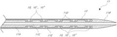
- an endoluminal staple or tack devicecan include one or more of the following features: a single column cell design, controlled angle of struts, tapered struts, struts having more than one sinusoidal pattern amplitude, a row of anchors, anchors in the middle of the device, flat midline markers, simultaneous device placement, and a force curve with a slope of about ⁇ 0.3 N/mm or less.
- an endoluminal stapleis provided with a force curve having a slope within a range of about ⁇ 0.1 to about ⁇ 0.3 N/mm. In other embodiment, an endoluminal staple is provided with a force curve having a slope within a range of about ⁇ 0.06 to about ⁇ 0.1 N/mm. In other embodiment, an endoluminal staple is provided with a force curve having a slope within a range of about ⁇ 0.006 to about ⁇ 0.06 N/mm.
- a catheter based endoluminal staple deviceor plaque tack
- a catheter based endoluminal staplecan include proximal and distal circumferential members.
- the proximal circumferential membercan be disposed at a proximal end of the endoluminal staple.
- the distal circumferential membercan be disposed at a distal end of the endoluminal staple.
- the distal circumferential memberis the distal most aspect of the endoluminal staple and the proximal circumferential member is the proximal most aspect of the endoluminal staple.
- the proximal and distal circumferential memberscan be connected by bridge members.
- the bridge memberscan divide an outer surface of the endoluminal staple into cells bounded by the bridge members and a portion of each of the proximal and distal circumferential members.
- a catheter based endoluminal staplecan include proximal and distal circumferential members.
- the proximal circumferential membercan be disposed at a proximal end of the endoluminal staple, the proximal circumferential member having a sinusoidal configuration.
- the distal circumferential membercan be disposed at a distal end of the endoluminal staple, the distal circumferential member having a sinusoidal configuration.
- the distal circumferential memberis the distal most aspect of the endoluminal staple and the proximal circumferential member is the proximal most aspect of the endoluminal staple.
- the endoluminal staplecan include a first plurality of distally extending apices having a first amplitude and a second plurality of distally extending apices having a second amplitude greater than the first amplitude. It may also, or alternatively, have a first plurality of proximally extending apices having a first amplitude and a second plurality of proximally extending apices having a second amplitude greater than the first amplitude.
- the endoluminal staplecan include a bridge member connecting each apex of the second plurality of apices of the proximal circumferential member to each apex of the second plurality of apices of the distal circumferential member.
- each apex of the first plurality of apices of the proximal circumferential membercan be unconnected to each apex of the first plurality of apices of the distal circumferential member at a corresponding circumferential position.
- a stapleis configured with a plurality of struts on a circumferential member and one or more angles between the struts is controlled.
- the angles of the outward apexes of the circumferential membercan be controlled.
- an endoluminal staplein other embodiments, includes a plurality of circumferential members, at least one of which comprises a plurality of struts.
- the strutscan be configured with a taper along their length, to control the manner in which the struts are loaded.
- the tapercan be the same or different along each strut or along each type of strut.
- each circumferential membercan be made up of a pattern of repeating struts, with each type of strut having a particular taper.
- the strutscan alternate from a wider end to a shorter end and then the next strut can have a shorter end followed by a wider end. Other configurations are also possible, increasingly wider struts being just one additional example.
- a circumferential member with a plurality of strutscan be on a distal end of an endoluminal staple.
- a first strutcan be tapered such that a proximal portion of the strut is narrower than a distal portion of the strut.
- a second strutis connected to the first strut at distal ends of the first and second struts.
- the second strutcan have the same or a different taper.
- the second strutcan also have a proximal portion narrower than a distal portion of the second strut, while also being narrower overall than the first strut.
- a third strutcan be connected to the second strut at proximal ends of the second and third struts.
- the third strutcan have a proximal portion of the strut that is wider than a distal portion of the strut.
- a fourth strutcan be connected to the third strut at distal ends of the third and fourth struts.
- the fourth strutcan have a proximal portion of the strut that is wider than a distal portion of the strut.
- the fourth strutcan have the same or a different taper from the third strut. For example, the fourth strut can wider overall than the third strut.
- an endoluminal staplehas a first circumferential member disposed at a distal end of the endoluminal staple, the first circumferential member comprising a repeating pattern of first and second outward apices spaced apart by first and second inward apices. The amplitude of the second outward apices can be less than the amplitude of the first apices.
- the endoluminal staplecan also have a second circumferential member disposed at a proximal end. The second circumferential member can be a mirror image of the first circumferential member.
- an endoluminal staplehas a first circumferential member disposed at a distal end of the endoluminal staple and a second circumferential member disposed at a proximal end.
- the second circumferential membercan be a mirror image of the first circumferential member.
- the first and second circumferential memberscan be connected by a plurality of bridge members.
- the bridge memberscan include one or more anchors configured to engage the plaque and/or the blood vessel wall.
- an endoluminal staplecan be configured for simultaneous deployment wherein the entire staple is released from the delivery catheter prior to the staple contacting the blood vessel lumen where it is to be placed. Simultaneous deployment is most likely in larger vessels, for example, vessels larger than (e.g., having a diameter that is larger than) 80% of the length of the staple will generally permit simultaneous deployment.
- vesselsinclude superficial femoral artery, iliac, popliteal, and tibial.
- an endoluminal stapleis provided with features that allow the staple to remain in a delivery catheter after a delivery sheath has been withdrawn releasing at least part of, or an entire circumferential member.
- the circumferential membercan make up almost one half of an axial length of the staple.
- the staplecan also be configured for simultaneous deployment when released.
- an endoluminal staplecan have a force curve with an extended area having a low slope.
- a force curveplots the amount of expansive force exerted, e.g., radially outwardly directed, by a self expanding staple or stent when moving from a compressed state to an expanded state.
- the low slope of the force curvecan be over a 2.5 mm outer diameter expansion range with a change in force of less than 1 N. In some embodiments, the slope can be less than ⁇ 0.3 N/mm.
- a tack devicecan be used in a method to treat any plaque dissection in the blood vessel after balloon angioplasty by installing the tack with an expansion force against the plaque to hold it against the blood vessel walls.
- One methodencompasses one wherein balloon angioplasty is first performed, and if there is any damage, disruption, dissection, or irregularity to the blood vessel caused by the balloon angioplasty mechanism, one or more tack devices may be used to tack down the damaged, disrupted, dissected, or irregular blood vessel surface, so as to avoid the need to install a stent and thereby maintain a “stent-free” environment.
- FIG. 1illustrates the use of a stent installed after angioplasty as conventionally practiced in the prior art.
- FIG. 2illustrates the use of plaque tacks installed after an endolumenal procedure demonstrating advantages over the prior art.
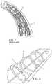
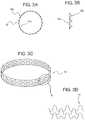
- FIG. 3Ashows an embodiment of a plaque tack in end view
- FIG. 3Bshows it in side view
- FIG. 3Cshows the plaque tack in perspective
- FIG. 3Dshows a section of the plaque tack in a flat or rolled-out view.
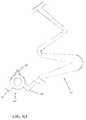
- FIG. 4is a schematic representation of a distal portion of a delivery device that has been advanced to a treatment site expanded in the blood vessel.
- FIG. 4Aillustrates the proximal end of one embodiment of a delivery device.
- FIG. 4Bis a plan view of the distal portion of the delivery device shown in FIG. 4 .
- FIG. 4Cis a cross-sectional view of the distal portion of FIG. 4B showing a plurality of tack devices prepared for implantation.
- FIG. 4Dshows the deployment of two tack devices upon retraction of a sheath.
- FIGS. 5A and 5Bshow another embodiment of a plaque tack in a collapsed state and in an expanded state, respectively.
- FIG. 5Cshows a detail view of a section of the plaque tack of FIG. 5A-B .
- FIG. 5Dshows a variation on the embodiment of FIGS. 5A-5C having an anchor disposed on a midline of the tack.
- FIG. 5Eshows a variation with struts that taper from wider at a lateral edge of a tack to narrower at a mid-section of the strut and/or from narrow at a mid-section of a strut to wider adjacent to a medial location of the tack.
- FIG. 6Ais a chart comparing the expansion forces of a plaque tack to a stent.
- FIG. 6Billustrates the use of multiple plaque tacks which are spaced apart over the length of a treatment site as compared to a typical stent.
- FIG. 7Ashows another embodiment of a plaque tack in a fully compressed state.
- FIG. 7Dshows the plaque tack in a fully expanded state and
- FIGS. 7B and 7Cshow the plaque tack in states of expansion between the fully compressed and expanded states.
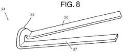
- FIG. 8is a schematic view of the focal elevating element of a plaque tack in FIGS. 7A-D .
- FIG. 9is a schematic diagram illustrating the variables for computing the elevated tack surface due to the use of focal elevating elements in a plaque tack device.
- FIG. 10illustrates use of a plaque tack with focal elevating elements for holding a plaque against a blood vessel wall.
- FIGS. 11 and 12illustrate a variant use of focal elevating elements on a plaque tack.
- FIGS. 13 and 14illustrate another variant of focal elevating elements on a plaque tack.
- FIG. 15illustrates the use of focal elevating elements to reshape artery walls into a desired cross-sectional shape.
- FIGS. 16-22illustrate variations in forming and positioning focal elevating elements on the struts of a plaque tack.
- FIGS. 23-29illustrate a method of delivery of a plaque tack into a blood vessel.
- FIGS. 30A-Bshow a focal elevating element engaging plaque.
- FIGS. 31A-Bshow anchors engaging plaque.
- the subject matter of this applicationis directed to the improvement of a plaque tack or staple device.
- the plaque tack or staple devicecan be used for treating atherosclerotic occlusive disease.
- the plaque tackcan be used to hold loose plaque against a blood vessel wall.
- the plaque tackcan include an annular member configured to apply an expansion force to the loose plaque.
- FIG. 2shows one embodiment of a plaque tack or staple device 5 that includes a thin, annular band or ring of durable, flexible material.
- the tack devicecan be inserted into a blood vessel in a compressed state and installed in an expanded state against the blood vessel wall using a catheter delivery mechanism at one or more specific positions of loose plaque.
- the plaque tack 5can be deployed after or as part of an angioplasty procedure.
- the plaque tack 5is adapted to apply an expansion force against the plaque in the blood vessel 7 to press and hold the plaque against the blood vessel walls.
- the tack devicecan be radially outwardly expandable under a spring or other expansion force.
- the fully expanded diameter of the tack 5is greater than the transverse size of the vessel to be treated.
- the tack 5advantageously can be deployed in a surprising large range of blood vessel sizes.
- the plaque tack 5can include a plurality of plaque anchors 9 on its outer annular periphery.
- the plaque anchors 9can be embedded into or at least placed in physical contact with plaque by expanding up against the plaque.
- the plaque anchors 9are adapted to elevate adjacent sections of the tack 5 relative to the wall of the vessel. In at least this sense, the anchors 9 may have some of the advantages of focal elevating elements that are discussed in SECTION III below.
- the anchors 9exert a holding force on the plaque while minimizing the amount of material surface area in contact with the plaque or blood vessel wall.
- the plaque tack 5can extend over only a small area in the axial direction of the vessel wall, in order to minimize the amount of foreign structure placed in the blood vessel.
- each plaque tack 5can have an axial length L that is only a small fraction of the axial length of a typical stent.
- the plaque tack devices of the present applicationare designed as a minimally invasive approach to tacking loose or dissected atherosclerotic plaque to the wall of the artery, as illustrated in FIG. 2 .
- the plaque tackmay be used to treat either de novo atherosclerotic lesions or the inadequate results of balloon angioplasty.
- the plaque tackis designed to maintain adequate lumen in a treated artery without the inherent disadvantages of vascular stents.
- the devicemay also be used to administer medications, fluid, or other treatment (“eluting”) agents into the atherosclerotic plaque or the wall of the blood vessel or into the bloodstream.
- One or more plaque tacks 5can be accurately deployed in positions along the length of a plaque accumulation site where specific holding forces are needed to stabilize the site and/or hold pieces of plaque out of the way of blood flow.
- FIG. 2shows that in various plaque tack treatments, a plurality of plaque tacks 5 can be deployed to treat locations that are axially spaced along the vessel 7 .
- targeted treatmentscan be provided to hold loose plaque against a vessel wall without over-scaffolding as discussed below.
- the plaque tack 5 and installation proceduremay be designed in a number of ways that share a common methodology of utilizing the outward force of a spring-like annular band to enable the tack to be compressed, folded, or plied to take up a small-diameter volume so that it can be moved into position in the blood vessel on a sheath or catheter, then released, unfolded or unplied to an expanded state within the blood vessel.
- the plaque tack devicecan be delivered into the blood vessel from endovascular insertion.
- SECTION IVdiscusses a variety of delivery methodologies and devices that can be used to deploy plaque tacks.
- the delivery device for the different embodimentscan be the same, or can be different with features specifically designed to deliver the specific tack.
- the plaque tack and installation proceduremay be designed in a number of ways that share a common methodology of utilizing an expansion force of the delivery mechanism (such as balloon expansion) and/or the expansion force of a compressible annular band to enable the tack to be moved into position in the blood vessel, then released, unfolded or unplied to an expanded state within the blood vessel.
- Variations of the plaque tack 5can have a mesh-like configuration and can be arranged with one or more circumferential members formed with discrete struts, such as in open and closed cell constructions, among other designs.
- FIGS. 3A-D , and 4An embodiment of a plaque tack 10 in the form of a metallic mesh construction is illustrated in FIGS. 3A-D , and 4 .
- the plaque tack 10is shown having a closed cell construction with an annular band 10 a formed of interleaved mesh, and radially outwardly extending projections 10 b .
- the plaque tack 10may be laser cut or etched out of a metal tube form or made of thin metal wire which is looped and interleaved in a mesh that is welded, soldered, looped and/or linked together into the desired mesh shape as can be seen in FIGS. 3C-D .
- the projections 10 bcan project out from the annular band 10 a .
- the projections 10 bcan be on an outer surface of the tack and can contact and/or embed into the wall of a blood vessel.
- the annular band of the plaque tack 10can have a dimension in the axial direction of the vessel walls (sometimes referred to herein as length) that is about equal to or less than its expanded diameter, in order to minimize the emplacement of foreign scaffolding structure in the blood vessel. Expanded diameter means final diameter in an unconstrained expansion.
- One or more tackscan be applied only in positions along the length of a plaque accumulation site where specific holding forces are needed to stabilize the site and/or hold pieces of plaque out of the way of blood flow.
- the mesh patterncan be designed so that the plaque tack 10 can be compressed radially inward to a smaller-volume size. This can allow the plaque tack 10 to be loaded onto or within a catheter delivery device to be inserted into the blood vessel.
- the tack 10can have an overall circular shape with bends, such as inner V bends, that allow it to be folded in zig-zag fashion to a compressed smaller-volume form for loading in a delivery catheter, such as a deployment tube.
- the compressed plaque tack 10is released from the delivery catheter.
- the mesh combined with an annular, ring shapecan allow the plaque tack 10 to spring back to its expanded shape.
- the tack 10can be expanded by another device, such as by a balloon.
- FIG. 3Cshows the plaque tack 10 at rest in its fully expanded state and
- FIG. 3Dshows a detail of a section of the metallic mesh.
- FIGS. 4-4Dshow that one or more plaque tacks 10 can be positioned in a patient's vasculature at a treatment site by a delivery device 11 with an outer sheath 13 and thereafter expanded.
- the tack 10can be expanded in any suitable way, such as by being configured to self-expand or to be balloon expanded.
- a plurality of self-expanding tacks 10(or variants, such as tack 10 ′ or tack 10 ′′) is disposed inside the sheath 13 .
- the delivery device 11includes an elongate body 11 A that is disposed at least partially within the sheath 13 .
- the delivery device 11also includes a dilating structure 11 B that atraumatically displaces tissue and helps to guide the delivery device 11 through the vasculature.
- the body 11 Acan be configured with a lumen 11 C extending therethrough for receipt and slideable advancement of a guidewire 40 therein.
- the sheath 13 and the dilating structure 11 Bmeet to provide a smooth outer surface to the delivery device 11 , e.g. having the same outside diameter where they meet.
- the body 11 Acan be configured with a plurality of annular recesses 11 D in which tacks 10 , 10 ′, 10 ′′ can be disposed.
- the annular recesses 11 Dcan be defined between one or more shoulders 11 E that prevent proximal or distal slippage of the tacks along the elongate body 11 A.
- the recesses 11 Dcould be eliminated by providing another structure for axially fixing the tacks 10 , 10 ′, 10 ′′ along the elongate body 10 A.
- FIGS. 4A and 4Dshow a proximal end of the device 11 and a manner of deploying the tacks 10 , 10 ′, 10 ′′.
- the proximal end of the device 11includes a handle 11 F and an actuator 11 G.
- the actuator 11 Gis coupled with a proximal end of the sheath 13 such that proximal and distal movement of the actuator 11 G cause proximal and distal movement of the sheath 13 .
- FIG. 4Aillustrates a distal positioning of the actuator 11 G which corresponds to a forward position of the sheath 13 relative to the elongate body 11 A and the recesses 11 D.
- the projections 10 b on the surface of the tack 10can act as anchors or elevating elements to embed into or press against the plaque.
- An array of anchors or elevating elementscan be used for linking the annular band of the tack with the plaque mass or blood vessel wall.
- the projections 10 bcan be made of a sufficiently rigid material to sustain a locking or engaging relationship with the blood vessel tissue and/or to pierce or engage the plaque and maintain the locking or engaging relationship therewith.
- the projections 10 bmay project at an angle of 90 degrees to the tangent of the annular band, or an acute angle may also be used.
- the plaque tackmay be made of a material such as a corrosion-resistant metal, polymer, composite or other durable, flexible material.
- a preferred materialis a metal having “shape memory” (such as Nitinol).
- a tackmay have an axial length of about 0.1 to 6 mm, an expanded diameter of about 1 to 10 mm, and an anchor height from 0.01 to 5 mm.
- the annular band of the plaque tackhas a length in the axial direction of the vessel walls that is about equal to or less than its diameter, in order to minimize the amount of foreign structure to be emplaced in the blood vessel.
- the annular bandcan have a ratio of axial length to diameter as low as 1/100.
- FIGS. 5A-5Cillustrate that in certain embodiments, a plaque tack 10 ′ can be configured with an open cell structure.
- the plaque tack 10 ′can include one or more circumferential members that have undulating, e.g. sinusoidal, configurations and that are spaced apart in the axial direction.
- the circumferential memberscan be coupled together at one or more circumferentially spaced locations by axially extending members, sometimes referred to herein as bridge members.
- bridge memberssometimes referred to herein as bridge members.
- the plaque tack 10 ′can have features similar to those described above with respect to the plaque tack 10 .
- the plaque tack 10 ′may also be laser cut or etched out of a metal tube form.
- the plaque tack 10 ′may be made of a material such as a corrosion-resistant metal (e.g., certain coated or uncoated stainless steel or cobalt-chromium alloys), polymer, composite or other durable, flexible material.
- a preferred materialis a metal having “shape memory” (such as Nitinol).
- FIGS. 5A-Bshow the overall structure of the plaque tack 10 ′ with an open cell arrangement.
- the plaque tack 10 ′is shown having two circumferential members 12 , which can be rings formed by a plurality of zig-zag struts, joined by bridges 14 that extend between the rings 12 .
- the rings and bridgesdefine a column of bounded cells 16 along an outer surface of the tack.
- the outer surfaceextends about an outer periphery, e.g., an outer circumference of the tack 10 ′.
- the boundary of each of the cells 16is made up of a number of members or struts.
- the second ringis a mirror image of the first ring, though the first and second rings may be circumferential members with different configurations.
- the bridges 14can be symmetrical across a transverse plane extending through the axial mid-point thereof, though other configurations are also possible.
- the rings 12can be considered coaxial, where that term is defined broadly to include two spaced apart rings, or structures, having centers of rotation or mass that are disposed along a common axis, e.g., the central longitudinal axis of the tack 10 ′.
- FIG. 5Cis a schematic flat depiction of a portion of a tack 10 ′ illustrating a portion of the cell 16 and a portion of a boundary thereof.
- the portion illustrated to the right of the midline Cis one half of the cell 16 in one embodiment.
- the other halfcan be a mirror image, as shown in FIGS. 5A-B , an inverted mirror image, or some other configuration.
- the portion of the ring 12 that is part of an individual cell 16can define a portion that is repeated in a pattern along the ring.
- the ring 12can have portions that are repeated in a pattern that extends across cells, such as across 1.5 cells, 2 cells, 3, cells, etc.
- the pattern of the rings 12 combined with other features of the tack 10 ′can enable it to be circumferentially compressible.
- the difference between the compressed and expanded statescan be seen by comparing the compressed view shown in FIG. 5A and the expanded view shown in FIG. 5B .
- the cells 16 of the tack 10 ′can be bounded by portions of two rings 12 , which can be mirror images of each other. Thus, some embodiments can be fully described by reference to only one side of the tack 10 ′ and of the cell 16 .
- the ring 12a portion of which is illustrated in FIG. 5C , has an undulating sinusoidal pattern.
- the undulating patterncan have one or more amplitudes, such as the dual amplitude configuration shown.
- the rings 12can have a plurality of struts or structural members 26 , 27 , 28 , 29 .
- the plurality of strutscan repeat about the circumference of the ring 12 .
- the strutscan be many different shapes and sizes.
- the strutscan extend in various different configurations.
- the plurality of struts 26 , 27 , 28 , 29extend between inward 18 , 19 and outward apices 24 , 25 .
- the outward apices 24 , 25extend axially different distances as measured from a central zone or midline C of the tack 10 ′.
- the apex 24can be considered a high apex and the apex 25 can be considered a low apex in this regard.
- the inward apices 18 , 19may be axially aligned, e.g., being positioned at the same axial distance from the midline C.
- the outward apex 24is disposed farther away from the bridge and inward apices than the outward apex 25 .
- the axial length of the tack 10 ′is measured from the top of the outward apex 24 on one side of the cell 16 to the corresponding top of the outward apex 24 on the other side of the cell.
- the first outward apex 24extends a first axial distance from the midline C of the tack 10 ′ and the second outward apex 25 extends a second axial distance from the central zone C of the tack 10 ′, the first distance being greater than the second distance.
- Each side of the cell 16 as shownhas one high outward apex 24 and one low outward apex 25 .
- the bridge 14can be connected to the one or more of the inward apices 18 , 19 .
- the bridge 14can join the two rings 12 together.
- the bridge 14can have many different shapes and configurations.
- Some embodiments of the tack 10 ′have a proximal ring and a distal ring with the bridge disposed between and connecting them.
- the bridge 14can be located at the central zone or midline C of the tack 10 ′.
- the word “proximal”refers to a location on the tack 10 ′ that would be closest to vascular access site than the portion labeled “distal”.
- the tack 10 ′can also be thought of as having a medial portion that corresponds to the midline C and lateral portions extending in both directions therefrom.
- the location labeled “proximal”is also a medial location and the location labeled “distal” is also a lateral position. All of these terms may be used herein.
- the bridge 14is connected to each ring at the inward apex 18 .
- a bridgeis connected to every inward apex, forming a closed cell construction.
- the bridge 14is connected to every other inward apex, every third inward apex, or spaced farther apart by as needed, forming a variety of open cell configurations.
- the number of bridges 14can be chosen depending upon the application. For example, six or fewer bridges 14 may be used between the two rings 12 when desired for limiting neointimal hyperplasia.
- One technique for enhancing the plaque holding capability of the bridges 14is to align plaque holding structures (such as the barb 9 , projections 10 b , or the anchors discussed below) with a force application location or direction of the ring 12 .
- at least a portion of the bridge 14can be aligned, with one of the struts of the ring 12 .
- that connecting portion of the bridgecan extend therefrom in a manner that is aligned, partially or substantially aligned with a strut.
- FIG. 5Cshows that the bridge 14 is connected to the inward apex 18 and that the connecting portion of the bridge is substantially aligned with the strut 26 .
- a plaque holding structure of the bridge 14is disposed on a projection of a longitudinal axis L A of the strut 26 .
- the tack 10 ′has a plurality of anchors 20 .
- the axis L Aintersects a portion of an anchor 20 to maximize a torque effect from the expanded strut 26 to the anchor 20 .
- an anchor on an opposite side of the centerline Cis disposed on the projection of the axis L A and the projection of a longitudinal axis L A of a mirror image strut 26 intersects the anchor 20 of the strut on the same side of the centerline C as the strut 26 shown in FIG. 5C .
- the projection of the strut 26 and its mirror image strutcan be aligned with the centerline C, which is rigidly coupled with the anchors 20 .
- the bridge 14also is aligned with a high amplitude sinusoidal section of the tack 10 ′.
- the tack 10 ′can include one or more of anchors, markers and focal elevating elements, among other features.
- FIG. 5Cshows that the plaque tack 10 ′ can include a plurality of (e.g., two) anchors 20 .
- the tack 10 ′also can include a position marker 22 on each bridge 14 .
- the position markers 22can be fluoroscopically opaque and in one arrangement are generally flat.
- flat markersare arranged to have a planar outer face that is tangential to a cylinder that extends through an outer surface of the tack 10 ′ or that is concentric with the outer surface but disposed radially inside the outer surface.
- the anchors 20can similarly be configured to be tangential to a cylinder that extends through an outer surface of the tack 10 ′.
- a series of unique design featurescan be integrated into the tack 10 ′ for dynamic distribution of stresses within the tack 10 ′.
- These design featurescan enable the uniform control of the tack 10 ′ during compression, expansion, delivery, and catheter release.
- the design featurescan also individually and/or collectively manage the stresses throughout the bulk of the tack, along the struts, and at the interface of the tack and the blood vessel lumen.
- Better control of the distribution of stresses within the tackhas the benefit of reducing cellular response and tack fracture by limiting strut fatigue and the associated micro-rubbing at the tack-blood vessel interface.
- Micro-rubbingincludes a variety of small scale adverse interactions between implants and patient tissue, such as abrasion or friction that occurs on a cellular or intercellular level between the tack and the blood vessel lumen.
- a reduction in cellular responseis believed to be achieved partly through a reduction of surface area contact between the tack and the blood vessel lumen and partly by maximizing alignment of the contact points or structures with the blood vessel cells' natural orientation.
- the tackis able to move with the blood vessel while decreasing the micro-rubbing.
- Other devicessuch as stents, contact the blood vessel cells in ways that may extend across, e.g., transversely to, multiple cells increasing micro rubbing at the stent-blood vessel interface.
- the tack 10 ′ of FIGS. 5A-Cincludes a single column open cell design contained between two zig-zag rings. This arrangement provides minimal (if any) scaffolding of a vessel. In one sense, a ratio of the vessel contact area to the total treatment zone of the plaque tack 10 ′ is small.
- vessel contact areais the sum of the area of outer portions of the tack 10 ′ that may come into contact with the vessel wall. More particularly, the vessel contact area may be calculated as a summation for all of the struts of the length of each strut times the average transverse dimension (width) of the radially outer surface of each strut.
- the width of the radially outer surface of the strutmay be less than that of the radially inner surface.
- the vessel contact areamay also include the radially outer surface of the bridges 14 .
- the total treatment zone of the plaque tack 10 ′can be defined with respect to the fully expanded configuration in a best fit cylinder.
- a best fit cylinderis one that has an inner circumference that equal to the unconstrained circumference of the plaque tack 10 ′.
- the total treatment zonehas an area that is defined between the proximal and distal ends (or the lateral edges) of the plaque tack 10 ′.
- the total treatment zonecan be calculated as the length between the proximal and distal ends (or lateral edges) in the best fit cylinder times the inner circumference of the best fit cylinder.
- the length for purposes of determining the total footprintcan be the distance at the same circumferential position between high outward apices of the rings 12 .
- the ratio of the vessel contact area to total treatment zoneis less than 50%. In some embodiments, the ratio of the vessel contact area to total treatment zone is even less, e.g., 40% or less.
- the ratio of the vessel contact area to total treatment zonecan be as small as 20% or less. In specific examples, the ratio of the vessel contact area to total treatment zone is 5% or even 2% or less.
- focal elevating elementscan augment this advantageous feature, even further lowering the ratio of the vessel contact area to total treatment zone by providing separation between the vessel wall and at least a portion the circumferential members 12 .
- a vesselcan be treated by implanting a plurality of structures, e.g., plaque tack 10 ′.
- the structureshave a total contact area with the vessel wall.
- the total contact areamay be the sum of the vessel contact area of the individual structures.
- a total treatment zone areacan be defined as the surface area between the proximal end of the most proximal structure and the distal end of the distal most structure.
- the total contact areais no more than about 55% of the total treatment zone area. More typically, the total contact area is between about 10% and about 30% of the total treatment zone area. In specific examples, the total contact area is no more than 5-10% of the total treatment zone area.
- the tack 10 ′can also be understood to provide a relatively high open area within its lateral edges compared to stents. Distinct from traditional stents, the track 10 ′ need not include sufficient metal to provide a scaffolding function, to hold a vessel open. To accomplish many of the contemplated treatments, the tack 10 ′ can be configured to limit its contact to only a single point or a plurality of discrete points, for example at one or more axial locations. The discrete points can be widely spaced apart, such as by being points on a circumference that are separated by spaces or, when applied, vascular tissue.
- the open area bounded by lateral edges of the tack 10 ′dominates the total footprint, as defined above.
- the open area of the tack 10 ′can be defined as the sum of the areas of the cells 16 when the tack 10 ′ is in the fully expanded configuration, as defined above.
- the open areashould be calculated at the outer circumference of the tack 10 ′, for example the area extending between the internal lateral edges of each of the struts.
- internal lateral edgesare those that form at least a part of the boundary of the cells 16 .
- the sum of the radially outwardly facing surface of the struts of the tack 10 ′can be no more than about 25% of the open area of the tack 10 ′. More typically, the sum of the radially outwardly facing surface of the struts of the tack 10 ′ is between about 10% to about 20% of the open area of the tack 10 ′. In other examples, the sum of the radially outwardly facing surface of the struts of the tack 10 ′ is less than about 2% of the open area of the tack 10 ′.
- a single column designincludes arrangements in a plurality of tack cells are oriented circumferentially about a central axis of the tack 10 ′.
- Tack cellscan come in many configurations, but generally include spaces enclosed by struts and are disposed in the wall surface of the tack.
- Open cell designsinclude arrangements in which at least some of a plurality of internally disposed struts of proximal and distal circumferential members are not connected by bridges or axial connectors.
- FIG. 5Cshows that the inward apex 19 is unconnected to a corresponding inward apex on a mirror image ring 12 . Thus, a portion of the cell 16 disposed above the inward apex 19 in FIG.
- Open cell designshave increased flexibility and expandability compared to closed cell designs, in which each internally disposed struts of a proximal circumferential member is connected to a corresponding internally disposed struts of an adjacent circumferential member.
- the cell 16would be divided into two closed cells by connecting the inward apex 19 to a corresponding inward apex on the mirror image ring 12 .
- closed cell plaque tackscan be suitable for certain indications and can include other features described herein.
- the single column open cell designextends along the midline C of the bridge (and also, in this embodiment, along the circumference of the tack 10 ′).
- the cell 16is identical to a plurality of additional cells 16 that would be disposed circumferentially about the central axis of the tack 10 ′.
- the number of cellscan vary depending on factors such as the size of the vessel(s) for which the tack 10 ′ is configured, the preferred arrangements of the rings 12 , the number of bridges 14 to be provided and other factors.
- the tack 10 ′can include proximal and distal rings 12 connected by bridges 14 .
- the proximal ring 12can be disposed at a proximal end of the tack 10 ′.
- the distal ringcan be disposed at a distal end of the tack 10 ′.
- the distal ringis the distal most aspect of the tack 10 ′ and the proximal circumferential member is the proximal most aspect of the tack 10 ′.
- the bridges 14can divide an outer surface of the tack 10 ′ into cells 16 bounded by the bridges 14 and a portion of each of the proximal and distal rings 12 . In the embodiment of FIGS.
- FIG. 5Cincludes the terms “distal” and “proximal” for reference purposes related to this and other examples, thus the ring 12 shown is the distal ring. In other embodiments, the ring 12 shown can be the proximal ring.
- the cells 16can have one of many different shapes and configurations.
- FIG. 5Bshows that, the cells 16 are aligned as a repeating pattern forming a single column open cell design along the circumference of the tack 10 ′.
- Conventional stent designsare generally relatively long (e.g., 4 cm and even up to 20 cm when used in peripheral vasculature) from their distal to proximal ends. Where arranged with circumferentially disposed cells, conventional stents have a large number of columns of cells. These designs are burdened with repeating points of weakness and can generate stresses that become difficult to manage. As the device is put under stress and strain, these conventional stents must find regions of greater pliability within the strut matrix. These strut regions absorb the load throughout the system and under periods of repeated external forces begin to fail, such as through metallurgical friction loading.
- the single column configuration of the tack 10 ′is not subject to repeated weak point loading due to movement of remote stent portions because the tack does not have to be axially elongated to provide effective tacking treatment.
- Other benefits that derive from the shortnessinclude reduced friction at the interface with the catheter sheath during delivery and with the blood vessel wall. As discussed above, the stress at the blood vessel wall interface is reduced due to the lack of cell-to-cell dragging or pulling which in turn reduces the potential that the tack will pull or drag adjacent cells increasing cellular inflammation or histological response along the lumen wall.
- a single column or other axial short configurationalso reduces the stress along each strut because the overall length of single column or other axial short structures or configurations are less affected by the anatomical motion (e.g., bending, twisting, and rotating). This results, at least in part, from the anatomy shifting around short structures while longer structures do not allow the anatomy to shift and thus longer structures absorb more forces resulting from this anatomical motion.
- anatomical motione.g., bending, twisting, and rotating
- any motion between the surfaces of the tack and the blood vesselcan cause rubbing and friction. If the motion is very small it can be described as micro-rubbing, as discussed above. Even micro-rubbing produces a negative effect on both the tack 10 ′ and the biological cells of the blood vessel. For example, friction occurs when a portion of an implanted object moves while another portion is stationary or moving by a smaller amount. Differential amounts of moving over time weakens the material leading to fracture by processes such as work hardening. The biological cells become irritated by the friction and can respond by producing an inflammation response Inflammation can drive a variety of undesired histological responses including neointimal hyperplasia and restenosis.
- FIG. 5Cshows that the tack 10 ′ has two circumferential members or rings 12 which each have a plurality of internal angles, including ⁇ , and ⁇ .
- a first angle ⁇is defined at the first outward apex 24 between the struts 26 , 27 and a second angle ⁇ is defined at the second outward apex 25 between the struts 28 , 29 .
- the first angle ⁇can be greater than the second angle ⁇ .
- the first angle ⁇can be between 43° and 53°, or between 45° and 51°.
- the second angle ⁇can be between 31° and 41°, or between 33° and 39°.
- the first angle ⁇can be about 48°
- the second angle ⁇can be about 36°.
- the tack 10 ′has an expanded outer diameter of 7.5 mm and the first angle ⁇ can be 47.65° and the second angle ⁇ can be 35.56°.
- the plaque tack 10 ′can be formed from a tube stock with an initial outer diameter 4 mm. The tube stock can be expanded to 7.5 mm and then heat treated in that shape.
- the plaque tack 10 ′can be made of a shape memory material and the heat treatment step can be to engrain that particular shape into the “memory” of the material. The plaque tack 10 ′ can then be crimped or compressed and flash frozen in the compressed state to then be loaded onto a delivery device.
- a beneficial feature of the tack 10 ′is that the angle of the struts as they meet at each apex can be controlled in at least one of an expanded and a contracted state.
- the internal angles ⁇ , ⁇ of the outward apices 24 , 25can be controlled to be within ⁇ 5% of a selected nominal value. This control can be achieved for example, in the expanded state during the heat treatment during the manufacture of the plaque tack 10 ′.
- control of the anglescan beneficially offer relief from imperfections in the manufacturing process. In some cases, the control of other dimensions can be relaxed if these angles are sufficiently well controlled. By controlling these angles, production run quality can be improved. Such control has been found to enable repeatable, uniform, and balanced compressibility of the tack 10 ′ during the crimping cycle of manufacturing. These factors increase production run repeatability and offer ease of volume manufacturing which results in a reduction in overall cost of the part.
- control of the apex anglesallows the plaque tack 10 ′ to better distribute stresses along the circumferential members or rings 12 .
- the control of apex anglescan be used to control or distribute stresses within the ring 12 , e.g., uniformly along the length of the struts or non-uniformly to a region that can more robustly respond to stress loading.
- By distributing stress along the strutthe problematic localized stresses on the tack 10 ′, such as at vulnerable spots can be avoided during the expansion and crimping processes of manufacturing.
- the width of one or more of the struts 26 , 27 , 28 , 29 of the tack 10 ′can be different at different locations, e.g., can vary along the struts.
- the strutscan be tapered along their length. The taper can be the same or different along each strut or along each type of strut.
- each circumferential member or ring 12can be made up of a pattern of repeating struts, with each type of strut having a particular taper.
- FIG. 5Cshows that the ring 12 has a first strut coupled with a bridge 14 that is tapered such that a portion of the strut closer to the midline C (sometimes referred to herein as a medial portion or location) is narrower than a portion of the strut spaced farther away from the midline C (sometimes referred to herein as a lateral portion).
- a second strutis connected to the first strut at lateral ends of the first and second struts.
- the second strutcan have the same or a different taper.
- the second strutcan also have a medial portion narrower than a lateral portion of the second strut.
- the second strutcan be narrower overall than the first strut.
- a third strutcan be connected to the second strut at medial ends of the second and third struts.
- the third strutcan have a medial portion that is wider than a lateral portion thereof.
- a fourth strutcan be connected to the third strut at lateral ends of the third and fourth struts.
- the fourth strutcan have a medial portion that is wider than a lateral portion thereof.
- the fourth strutcan have the same or a different taper from the third strut. For example, the fourth strut can wider overall than the third strut.
- FIG. 5Cschematically illustrates the differences in the widths of the struts in one embodiment.
- the long struts 26 and the long strut 27have the same width at the same axial position and the short struts 28 and the short strut 29 have the same width at the same axial position.
- the struts 26 and the strut 27can have the same shape.
- the strut 28 and the strut 29have the same shape in some embodiments.
- the shape of the struts 26 , 27can be different form the shape of the struts 28 , 29 .
- the long strut 26 and the long strut 27have different widths at the same axial position and the short strut 28 and the short strut 29 also have different widths at the same axial position.
- the long struts 26 , 27are disposed at a first circumferential location of the tack 10 ′ adjacent to one of the markers 22 .
- the strut 26has a medial end connected to or forming a portion of one of the inward apices 18 and a lateral end disposed away from the inward apex 18 .
- the lateral endis coupled to the strut 27 at or adjacent to the outward apex 24 .
- the strut 26has a width W 4 adjacent to the medial end and a width W 2 adjacent to the lateral end.
- the width of the strut 26increases along the length thereof from the width W 4 to the width W 2 .
- the increase in width along the strut 26preferably is continuous along this length.
- the sides of the struts 26can be sloped relative to a longitudinal axis L A of the strut 26 .
- a first side 48 disposed between the longitudinal axis of the strut 26 and the strut 27can be disposed at an angle to (e.g., non-parallel to) the longitudinal axis of the strut 26 .
- a second side 46 of the strut 26can be disposed at an angle to (e.g., non-parallel to) the longitudinal axis of the strut 26 .
- both the first and second sides 46 , 48 of the strutcan be disposed at angles to the longitudinal axis of the strut 26 .
- the strut 27preferably also has different widths at different points along its length.
- the strut 27can be wider in a generally lateral direction adjacent to the outward apex 24 than it is adjacent to the inward apex 19 .
- the strut 27can have side surfaces that are angled relative to the longitudinal axis of the strut 27 .
- the strut 27can be tapered between its ends, e.g., having a continuously decreasing width along its length from wider adjacent to the outward apex 24 to narrower adjacent to the inward apex 19 .
- the strut 28extends from the strut 27 or inward apex 19 .
- the strut 28can have a medial end that is wider than a lateral end of the strut 28 and can have different widths at different points along its length.
- the side surfacescan also be angled relative to the longitudinal axis of the strut 28 .
- a strut 29can be connected to the strut 28 or outward apex 25 at a lateral end of the strut 29 .
- the strut 29can have a medial end that is wider than the lateral end thereof.
- the strut 29can have a taper that is the same or different from the strut 28 .
- the strut 29can be wider overall than the third strut.
- the strut 26can have a width W 2 of about 0.12 mm at the lateral end near the outward apex 24 and a width W 4 of about 0.095 mm at the medial end near the inward apex 18 and the strut 28 can have a width W 6 of about 0.082 mm near the outward apex 25 and a width W 8 of about 0.092 mm near the inward apex 19 .
- the change in thickness between W 4 /W 2 expressed as a percentagecan be between about 70% and about 90% more typically between about 75% and about 85%, and in certain embodiments about 80%.
- the taperingcan also be inverted, e.g., with the struts tapered from the ends (e.g., lateral edges) toward the medial portion.
- FIG. 5Eillustrates another variation in which the width of one or more of the struts of the tack can be different at different locations, e.g., can vary along the struts.
- a strut 27 ′can be provided that is similar to the strut 27 except that the strut 27 ′ is narrowest in a mid-section N.
- the strut 27 ′can have a lateral wide portion L adjacent to the outward apex 28 and a medial wide portion M adjacent to the inward apex 18 .
- the width of the strut 27 ′reduces along the length thereof from the lateral wide portion L toward the medial portion M.
- the strut 27 ′is continuously narrower along the length from the lateral end of the strut 27 ′ toward the midline of the strut.
- the strut 27 ′can be narrowed such that the ratio of width at the midline to width at the lateral end of the strut 27 ′, expressed as a percentage, is between about 20% and about 85%. In some embodiments, this percentage is between about 35% and about 75%.
- the taperingcan be such that this percentage is between about 55% and about 70%. From the medial wide portion, the strut 27 ′ can be narrowed along the length thereof.
- the strut 27 ′is continuously narrower along the length from the medial end of the strut 27 ′ toward the midline of the strut.
- the strut 27 ′can be narrowed such that the ratio of width at the midline to width at the medial end of the strut 27 ′, expressed as a percentage, is between about 20% and about 85%. In some embodiments, this percentage is between about 35% and about 75%.
- the taperingcan be such that this percentage is between about 55% and about 70%.
- FIG. 5Eprovides a greater range for compression and expansion in smaller diameter configurations. Smaller diameter configurations can be used in smaller body lumens, e.g., blood vessels.
- a tack with this configurationcan be formed out of 2.3 mm diameter tubing, whereas the embodiments of FIG. 5C are optimally formed out of 4.5 mm diameter tubing.
- the configuration of FIG. 5Ecan be used to make tacks that are suitable for a 4 French delivery device.
- Tacks configured as in FIG. 5Ecan have an unconstrained expanded size of between about 4.5 mm and about 6.5 mm.
- devices including the configuration of FIG. 5Ecan have an unconstrained expanded size of between about 5 mm and about 6 mm, e.g., between about 5.5 and about 6.0 mm.
- One embodimentexpands to about 5.7 mm when unconstrained.
- a unique inverse taper or variation in width along the strutis achieved by inverting the orientation of the taper between the short struts 28 , 29 and the long struts 26 , 27 .
- the longer struts 26 , 27go from a narrow width near the inward apices 18 , 19 to a broader width near the high outward apex 24 .
- the shorter struts 28 , 29are the opposite with a broader width near the inward apices 18 , 19 to a narrower width near the low outward apex 25 .
- the plaque tackcan distribute the stresses observed during compression and after deployment. This feature can also contribute to the control of the stress by distributing the region of stress more uniformly along the length of the strut. In some embodiments, it may be desirable to distribute the stress non-uniformly to regions more able to handle the stress.
- the ring 12 illustrated in FIGS. 5A-5Chas an undulating sinusoidal pattern.
- the axial extent of the ring 12can vary about the circumference of the ring 12 , for example providing a plurality of amplitudes as measured by the distance from an inward apex to an adjacent outward apex.
- the undulating patterncan have one or more amplitudes, such as the dual amplitude configuration shown. In the dual amplitude configuration the plurality of struts 26 , 27 , 28 , 29 extend between inward 18 , 19 and outward apices 24 , 25 .
- the outward apices 24 , 25alternate between a high outward apex 24 and a low outward apex 25 .
- “high”corresponds to a larger distance H 1 as measured from a central zone or midline C of the tack 10 ′ and “low” corresponds to a smaller distance H 2 as measured from the midline C ( FIG. 5C ).
- the varying amplitude of the long and short sinusoidal struts described abovecan provide additional control of the plaque tack's functionality.
- itcan enhance compression of the tack 10 ′ to provide a greater change in circumference from the fully expanded configuration to a compressed configuration when crimped during manufacturing.
- Greater compressibilityfacilitates delivery in smaller vessels and a greater range of indication that can be treated because it enables a smaller crossing profile delivery system.
- the height H 1 , H 2 of the apicesis measured from the center line C to the top of the respective outward apices 24 , 25 .
- the dual amplitude sinusoidal patterned plaque tack 10 ′such as that shown in FIGS. 5A-C , enables broad ranging conformable dimensions that can easily be scalable to different outer diameter designs.
- the open cell single column designallows broad range compression and expansion. This is partly due to the length of strut available for effective expansion.
- the ease of compressionis associated with the position of the apices disposed H 1 and H 2 from the center of the tack, which permits these apices to compress at a different locations instead of at the same lateral location. If H 1 and H 2 of the apices are aligned (e.g., at the same axial location) they would press against each other during compression limiting the compression range.
- the ranges of compression for the plaque tack 10 ′have been measured to 0.25 times nominal tube size in combination with ranges of expansion up to 2 times nominal tube size, although these are not the anticipated limits of the device. Combining these ranges the full range of compression has been measured at 0.125 times the heat treated outer diameter.
- the nominal tube sizeis 4.5 mm and the tube is expanded to 7.5 mm in the manufacturing process.
- the distance from the midline C of the device to the apex of the longer struts H 1is approx. 3.0 mm, while the distance H 2 to the apex of the shorter struts is approx. 2.6 mm.
- the energy stored in the shorter amplitude strutsoffers additional control of the plaque tack 10 ′ during the release phase of delivery within the blood vessel.
- the longer strutsare uncovered first followed by the shorter struts ( FIG. 5C ).
- This mismatchprovides greater retention forces to maintain the plaque tack 10 ′ in the delivery catheter and thus provides greater control of the plaque tack during delivery.
- FIGS. 5A-5Cillustrate that the plaque tack 10 ′ can include centrally disposed anchors 20 . While the anchors 20 are primarily for securing loose plaque, as discussed above, their placement and configuration enhance the control of the deployment and the performance of the tack 10 ′ once placed inside the blood vessel.
- the plaque tack 10 ′can be a self-expanding circumferential structure and the anchors 20 can be disposed on an outer portion of the tack.
- the anchors 20can be coupled with any portion of the tack 10 ′ but preferably are disposed adjacent to the midline C of the bridges 14 as discussed above.
- the tack 10 ′includes two anchors disposed on either side of the midline C as illustrated in FIG. 5C .
- a single anchorcan be provided on the midline C.
- at least three anchors 20can be provided, such as one on the midline and two on either side thereof as illustrated in FIG. 5C .
- the bridge 14can have two anchors on one side and one anchor on the other side connecting the two other anchors, as shown in FIG. 5D .
- an anchor 20 ′is located at the center of the tack 10 ′ along its axial direction.
- This embodimentprovides at least one anchor 20 ′ that is located on both sides of the midline C.
- the anchor 20 ′can be located on an opposite side of the marker 22 from the anchors 20 .
- plaquecan be anchored from a plurality of directions, e.g., a plurality of circumferential directions.
- the anchors 20are not present and a single anchor 20 ′ located on the midline C is provided.
- the embodiment illustrated in FIGS. 5A-Ccould also be modified to include one or more anchors on either side of the marker 22 , where anchors are currently only shown on one side.
- the plaque interaction of the tack 10 ′is primarily provided by the anchors 20 and to a lesser extent the bridges 14 .
- the anchorscan have a preferred penetration length into the plaque of 0.01 mm to 5 mm. In certain variations, the penetration length is within a range of about 0.03 mm to about 1 mm. In other variations, the penetration length is within a range of about 0.05 mm to about 0.5 mm.
- the bridges 14which can be disposed at alternating inward apices, as discussed above, can be configured to reside on a tangential plane of a cylinder when the tack 10 ′ is fully expanded and not being deformed by an outward structure.
- the tangent configurationcauses the anchors 20 to project outward toward from the cylindrical surface of the tack 10 ′.
- the anchorsare adapted to engage plaque or other vascular deposits causing the vessel to vary from its unobstructed fixed state, e.g. to be out-of-round.
- a technique for deploying the tack 10 ′involves positioning the tack in a hollow catheter body. When positioned in the catheter body, the tack 10 ′ is compressed to a compressed state.
- the rings 12are highly conformal due to their construction, discussed above. As a result, the rings fully appose to the inner luminal surface of the hollow catheter body.
- the bridges 14 and anchors 20are more rigid and therefore are less conformal and as a result bite into the inner luminal surface of the catheter body. This creates a retention force within the catheter and limits unintended movement of some or all of the tack 10 ′ toward a catheter deployment zone.
- the retention force of the barbs 20is maintained or increased after partial deployment of the tack 10 ′.
- a region of relatively high flexibilitycan be provided at the junction of the bridges 14 and the rings 12 . While high flexibility sections of stents can be areas of concern, such is not the case in the plaque tack 10 ′ for reasons discussed below.
- the flexible regioncan have any material property or structure to enhance its flexibility at least compared to that of the bridges 14 such that upon movement of the ring 12 on the leading edge of deployment, the tangential configuration and tendency of the anchors 20 to bite into the hollow elongate catheter body is not diminished. Such is the case even though the leading edge ring 12 may expand to at least one-half of its fully expanded size.
- the bridge 14is connected to each ring at the inward apex 18 where at least a portion of the bridge 14 can be aligned, partially or substantially aligned with one of the struts that make up the ring 12 as has been described.
- the bridge 14is aligned with a high amplitude sinusoidal section of the pattern.
- the region of relatively high flexibilitycan be disposed between the inward apex 18 and the bridge 14 .
- expansion of the ring 12may even cause the anchors 20 to rotate outward to increase the retention force in the catheter body.
- expansion of the strut 26may cause an inward deflection of the inward apex 18 .
- ring 12is expanding a slight rotation of anchors 20 may occur which may cause a torqued outward deflection of the leading anchor and a corresponding torqued outward deflection of the trailing anchor.
- the anchor 20 to the right of the midline Cmay be deflected inwardly toward the central axis of the catheter body but the anchor to the left 20 will be deflected outward to increase the retention force thereof.
- the plaque tack 10 ′may be retained in the catheter during such partial expansion. Due to this feature the plaque tack 10 ′ can be uniformly placed, as discussed further below in Section II.B.8.
- the out-of-cylinder nature of the bridges 14 and anchors 20also provide benefits to the deployed state.
- the plaque anchors 20are disposed radially outwardly of a cylindrical surface formed by the rings 12 .
- the degree of out-of-cylindercan depend on the application, but in general may be sufficient to space at least a portion of the cylindrical surface from the inner walls of the vasculature when deployed.
- the anchors 20 or the anchors combined with the rings 12can be configured as focal elevating elements, which are discussed below in SECTION III.
- the strutswill engage the vessel wall and/or plaque. It is anticipated that in most situations, at least some of the struts will be deformed in response to irregularities of shape within the blood vessel. At the same time, the bridges 14 are less deformable and thus will resist such deformation retaining a circular configuration. The outward forces that are applied by the strut members are transferred into those areas that are in contact with the blood vessel wall. In some cases, when the tack 10 ′ conforms to an irregularly shaped blood vessel lumen, the rigid central anchors become the region for blood vessel contact. The cumulative outward force of the struts in the rings 12 are applied through the bridges 14 to the anchors. Adjacent struts share their load with the contact region pressing the blood vessel into an enlarged configuration, such as a conformed circle.
- Such a configurationcan provide benefits such as helping the plaque tack 10 ′ to remain in place after delivery and allowing the plaque tack 10 ′ to respond dynamically to the movement and pulsing of the blood vessel itself.
- this configurationcan have the benefit of reducing cellular response and device fracture by limiting strut fatigue and associated micro friction loading at the tack-blood vessel interface.
- the bridge 14can include one or more anchor. In some embodiments, the bridge can be formed entirely of anchors.
- the surgeonAfter deployment of the plaque tack 10 ′, the surgeon has the option of placing an angioplasty balloon at the site of the tack and inflating the balloon to press the anchor or anchors 20 into the plaque and/or wall of the blood vessel.
- the plaque tack 10 ′has one or more markers 22 .
- a series of radiopaque markers 22can be located on the tack 10 ′.
- the radiopaque markers 22are at the midline C of the device.
- the radiopaque markers 22can be disposed between the two circumferentially oriented sinusoidal members or rings 12 .
- the radiopaque markers 22can be disposed adjacent to the plaque anchors 20 .
- the radiopaque markers 22can have one of many different shapes or configurations.
- the radiopaque markers 22have a planar or flat structure. As shown in FIG. 5C , each marker 22 is coupled with, such as by being press-fit or riveted into, a circular eyelet producing a flat leveled surface with the eyelet.
- the markers 22offer clear visibility of the tack 10 ′ in the catheter delivery system and provide guidance to the clinician for accurate placement during the procedure.
- the markers 22can offer a visible clue to the clinician of the point when the release of the device will take place. For example, once the markers 22 meet a marker strip located at the tip of a delivery catheter sheath the full device can be deployed.
- the plaque tack 10 ′can be configured for simultaneous placement within a blood vessel. Simultaneous placement of the plaque tack 10 ′ can be defined as the entire plaque tack 10 ′ being released from the delivery catheter prior to any all of the distal apices of the plaque tack 10 ′ contacting the blood vessel lumen where it is to be placed. This event can occur when the anchors 20 are completely uncovered by the catheter sheath allowing the entire plaque tack 10 ′ to expand against the lumen wall of blood vessel.
- the struts 26 , 27 , 28 , 29can be free floating, e.g., spaced from the vessel wall or applying negligible force to the wall, such that they do not contact the lumen wall prior to simultaneous placement.
- the anchors 20may have the effect of spacing a portion or substantially all of the struts 26 , 27 , 28 , 29 from the vessel wall.
- Other forms of focal elevating elementsare discussed below that can be used to space the tack 10 ′ from the lumen wall.
- Simultaneous placementoffers the clinician the ability to control placement up until the markers 22 and/or anchors 20 are uncovered which can generate a full expansion event (struts adjacent to or contacting the lumen wall).
- the full expansion eventdoes not occur until the anchors 20 are uncovered due mainly to internal forces of the tack 10 ′ urging the anchors 20 to engage the delivery sheath described above.
- Another benefit of simultaneous placementis the reduction of any inadvertent dragging or pushing of struts against or along the lumen surface during the placement of the plaque tack 10 ′. Due to the complexity and variation of disease, location of placement, and dissections morphology, the ability of the outer surface of the plaque tack 10 ′ to contact the lumen wall all at the same time is dependant on the deployment circumstances. However, the ability of the plaque tack 10 ′ to contact the lumen wall completely upon release from the catheter sheath within fractions of a second has been observed.
- plaque tack 10 ′can be configured with a force curve with an extended area having a low slope.
- a force curvesuch as that illustrated in FIG. 6A , shows the amount of expansive force exerted by a self expanding plaque tack 10 ′ or stent when moving from a compressed state to an expanded state.
- the expansion force of a devicecan be a factor in choosing the correct device to be placed in a particular blood vessel.
- FIG. 6Athe force curves of a SMART stent (i.e., a S.M.A.R.T.® Control transhepatic biliary stent by Cordis Corporation), another conventional stent, and a plaque tack having the wall pattern illustrated in FIG. 5A .
- the chartshows the radial force in Newtons (N) on the y-axis and the outer diameter of the device in millimeters (mm) on the x-axis. As the device is expanded or moved from the compressed state to the expanded state, the outer diameter increases. Because the devices are self expanding, they have a set amount of stored potential energy.
- the potential energyWhen released, the potential energy is converted into kinetic energy as the internal forces try to restore the device to its expanded shape. The kinetic energy can then have an impact on the blood vessel when the device is implanted. Also, if the plaque tack 10 ′ is not fully expanded a generally constant force will be applied to the vessel wall that corresponds to remaining potential energy stored in the tack 10 ′.
- FIG. 6Ashows a first dark line A 1 showing the compression of a 7.5 mm plaque tack 10 ′ from approximately 7.5 mm to approximately 2 mm of compressed diameter.
- This portion of the curvecan be thought of as the working portion, in which the force on the Y-axis is the force that the plaque tack 10 ′ would apply to a vessel wall upon expansion.
- the force on the Y-axisis the force that the plaque tack 10 ′ would apply to a vessel wall upon expansion.
- the outward force of the tack 10 ′ on the wallwould be well under 1.0 Newton (N).
- N1.0 Newton
- the range of outward forceis less than about 0.05 N+/ ⁇ about 30%.
- FIG. 6Ashows in a dimmer line A 2 the crimp performance of a SMART stent in a similar test.
- the SMART stentis a longer structure than the plaque tack 10 ′.
- the S.M.A.R.T.® stent testedwas 40 mm long with a 8 mm unconstrained outer diameter, whereas the tack that was tested was 6 mm long with a 7.5 mm unconstrained outer diameter.
- the comparison between the plaque tack 10 ′ and the SMART stentillustrates a difference that would still manifest with a comparable length version of the SMART stent.
- the line B 2has a much higher crimp force in a range from just over 8 mm to about 6.5 mm.
- the slope of the crimp forcedecreases and the crimp force increases at a much slower rate.
- the outward force at the fully crimped stateis much higher.
- the fully crimped state of the SMART stentcorresponds to a smaller diameter, the crimp force for a comparable diameter is much higher on the SMART stent.
- Line B 2illustrates the working zone of the SMART stent that was tested.
- Line B 2shows the outward force over the range of expansion from about 2 mm to about 6 mm.
- the slope of line B 2is much greater at all points along its range between 2 mm and 6 mm.
- the practical effect of this higher slopeis that the SMART stent is much more sensitive to changes in the bore size of the vessel into which the expanded plaque tack 10 ′ is deployed.
- a low slope of the force curvecan be essentially flat over about a 3 mm outer diameter expansion range. In other embodiments, a low slope of the force curve can be over a 2.5 mm outer diameter expansion range with a change in force of change less than 1 N.
- Factors in the ability of the tack to have a broad range where the radial forces change less than 1 Ninclude the midline anchors, dual amplitude struts, and the varying strut thicknesses, discussed above.
- FIG. 6Aillustrates another conventional stent having a compression curve A 3 and an expansion curve B 3 .
- the SMART stentis a widely used stent pattern.
- the curves A 3 , B 3represent another conventional stent design. Although the curves A 3 , B 3 have lower peak compression force at the left-hand side of the curve, the slope is still dramatically higher over the range of use than is the tack illustrated by curve A 1 , B 1 .
- the tackis radially self expandable through a range of at least about 2 mm, generally at least about 3 mm and typically through a range of at least about 4 mm or 5 mm, while exhibiting a radial expansion force of no more than about 5 N at any point throughout the range.
- the maximum radial expansion force throughout the expansion rangeis no more than about 4 N and preferably is no more than about 3 N.
- the tackis expandable over a range of at least about 3 mm (e.g., from about 3 mm to at least about 6 mm) and the radial expansion force is less than about 3 throughout that range.
- the change in expansion forcewill be no more than about 3 N and preferably no more than about 2 N throughout the expansion range.
- the expansion forcedrops from no more than about 2 N at 3 mm diameter to no more than about 1 N at 6 mm diameter.
- the difference between the radial force of compression and the radial expansion force at any given diameter throughout the expansion rangeis no more than about 4 N, generally no more than about 3 N, preferably no more than about 2 N and in one embodiment is no more than about 1 N.
- the tackis expandable throughout a range which includes 3 mm through about 6.5 mm and the difference between the compression force and expansion force at each point along the compression/expansion range differs by no more than about 2 N and preferably by no more than about 1 N.
- the outward force of the plaque tack 10 ′is preferred to be as low as possible, while providing sufficient force to hold the plaque against the lumen wall through a wide range of luminal diameters.
- forceis elevated, e.g., by two to three times the sufficient holding force, adverse side effects can occur. These can include irritating the cells of the vessel wall that are in contact with the device, which can lead to re-stenosis.
- a very low force deviceis preferred for the typical treatment, higher force devices may be useful where loose plaque is found at calcified lesions.
- One advantage to having a slow change in force as the device is expandingis the ability to predict the energy that the blood vessel experiences independent of the lumen diameter. Another value would be the reduction of necessary inventory for hospitals. For instance, it has been found that two part sizes of the tack 10 ′ shown in FIGS. 5A-C can be used for plaque tacking treatments in blood vessels located throughout the leg, from hip to ankle. This is believed to be due in great part to the tack 10 ′ having a slope of less than ⁇ 0.3 N/mm.
- plaque tack described hereinis to reduce the amount of implanted foreign material to a minimum while still performing focal treatment of the blood vessel condition so as to cause a minimum of blood vessel wall reaction and adverse post-treatment restenosis.
- the plaque tackis designed to have substantially less metal coverage and/or contact with the blood vessel surface, thereby inciting less acute and chronic inflammation (See FIG. 6B ). Reduced contact area of implanted material against the blood vessel wall is correlated with a lower incidence of intimal hyperplasia and better long-term patency.
- Substantially reduced length along the axial distance of the blood vesselpermits a more targeted treatment, correlates with less foreign body coverage of the blood vessel surface, avoids covering portions of the surface that are not in need of coverage, and correlates with both early and late improved patency of blood vessel reconstructions.
- the plaque tackcan be deployed only where needed to tack down plaque that has been disrupted by balloon angioplasty or other mechanisms. Rather than cover an entire area of treatment, the plaque tack can be placed locally and selectively, for example, not extending into normal or less diseased artery segments (See FIG. 6B ). This permits the blood vessel to retain its natural flexibility because there is minimal to no scaffolding when a small profile tack is used locally or even when multiple tacks are spaced apart over the area of treatment. Still further reduction in the pressure profile can be achieved by using “points-of-contact” to achieve higher pressure at focal points and lifting the neighboring strut section away from the blood vessel wall to reduce the overall load of the outward pressure elsewhere on the tack strut structure.
- One parameter for design of a plaque tackis having a tack axial length to expanded diameter (L/D) ratio of no more than about 2.0, often no more than about 1.5 and in some implementations no more than about 1.
- the tackhas about an L/D ratio of 0.8. That is, the length of the tack along the axis of the blood vessel is about equal to or less than the expanded diameter of the tack.
- the preferred plaque tackis thus shaped like an annular ring or band, whereas the typical stent is shaped like an elongated tube.
- the small-profile tackcan thus be used locally for targeted treatment of disrupted regions of the blood vessel surface with a minimum of foreign material coverage or contact.
- Testsshow that a plaque tack with an axial length/diameter ratio 1 causes almost no biological reaction or subsequent blood vessel narrowing in comparison to a traditional stent where the axial length is greater than the diameter, and usually much greater. Tests indicate that device L/D1 results in a reduction in scaffolding much less than that of the typical stent and causes less arterial wall reaction.
- a plaque tack of minimal footprintmay be used such as a single, thin ring-type tack with an L/D ratio in the range of 1/10 to 1/100.
- axial length of a stentis correlated with a tendency for occlusion in multiple vascular territories. The more stent axial length that has been placed, the higher likelihood that the reconstruction will fail.
- the axial length of a stentis also directly linked to the frequency and tendency of the stent to break when placed in the superficial femoral artery.
- the medical literatureindicates that the superficial femoral artery performs like a rubber band, and it is likely that changes to the natural elongation and contraction of the superficial femoral artery play a significant role in the failure mode of superficial femoral artery stents.
- the small-profile plaque tackcan be implanted only in local areas requiring their use, thereby enabling the blood vessel to retain its natural flexibility to move and bend even after the surface has undergone tacking.
- Multiple tacksmay be implanted separated by regions free of metallic support, thereby leaving the artery free to bend more naturally.
- Outward radial pressure exerted on the blood vessel wallcan also be substantially reduced by the small-profile tack design, even when multiple tacks are used in a spaced-apart configuration.
- a series of anchor barbs or focal elevating elementscan be utilized. The presence of these features applying focal pressure to the wall of the artery allows the rest of the tack to apply minimum outward force to the artery wall. The points which apply the pressure can be very focal, and this is where the most force is applied. The focal nature of the application of the pressure exerted by the tack also minimizes the structural effects of the device. Uniformly distributed anchors or focal elevating elements can provide a distribution of radial energy maximizing the tendency to form a circular lumen.
- CVessel Coverage Area
- TVSTotal Vessel Surface area
- Cis the length of the prosthesis (e.g., stent or tack) times the average circumference of the vessel in which it is placed and the value TVS can be the length of the lesion or area requiring treatment times the same nominal circumference.
- Thiscan also be simplified to a ratio of total length of the prosthesis when expanded to the nominal circumference divided by the length of the lesion in the vessel.
- a simplified ratiocould be total non-overlapping length divided by lesion length or could be the sum of the length of the prostheses divided by the sum of the length(s) of the lesion(s).
- the C/TVS ratiois in the range of about 60% or less, whereas for a stent it can be 100% or more (if applied to overlap the treatment site).
- the conventional treated vessel lengthis X+10 mm to 20 mm where X is the length of the lesion and the added length is adjoining on normal or less diseased artery proximal or distal to the lesion.
- Xis the length of the lesion and the added length is adjoining on normal or less diseased artery proximal or distal to the lesion.
- the entire treated vessel lengthwould be covered with a stent.
- the treated vessel lengthwould be 3 to 4 cm (usually a single stent of this length would be selected), so that C/TVS is 150%-200%.
- tack placementabout 1 ⁇ 2 of X would be covered, and none of the adjoining normal or less diseased artery would be treated.
- approximately 1 cmwould be covered, so that the C/TVS ratio is about 60% or less.
- An advantageous aspect of this innovative approachis placement of bands only in regions of dissections requiring vascular tacking.
- a tack device 10 ′is formed with rings or mesh bands 12 connected by longitudinal bridge members 14 ( FIG. 5A ).
- the tack 10 ′is shown compressed for delivery in a blood vessel. When expanded, the diameter of the tack device can be about equal to the axial length of the tack device.
- FIG. 6Billustrates the use of multiple tack devices which are spaced apart over a length of blood vessel at a treatment site as compared to a typical stent.
- the spacing between tack devicesis at least the axial length of the tack device. Note that the spacing between adjacent tack devices leaves untreated vessel area.
- a typical stentis shown in the upper part of the figure compared to the use of 6 spaced-apart tack devices at the bottom part of the figure.
- the overall length of treatment areais 6.6 cm (the same length of the stent) while each band is shown as 6 mm long separated by 6 mm spaces.
- Cis equal to 6 ⁇ 0.6 cm ⁇ 0.6 ⁇ , or 6.78 cm 2
- TVSis 12.44 cm 2
- the C/TVS ratiois equal to 54.5%.
- Optimal spacingis a minimum of l tack axial length apart for tacks. This permits the artery to maintain its flexibility, and only a half or less of the treated length of the artery will be covered with metal. It should be noted that in the case where restenosis occurs after tack placement the overlapping of the entire treated length with a stent still allows the stent to retain its patency. This is due to the repeated pattern of regions where no tacks are placed offering regions of relief and the artery to flex.
- stent designmay be the ratio of Relative Metal Surface Area (RMS) and the number of longitudinal segments in the device structure, for example, as presented by Mosseri M, Rozenman Y, Mereuta A, Hasin Y, Gotsman M., “New Indicator for Stent Covering Area”, in Catheterization and Cardiovascular Diagnosis, 1998, v. 445, pp. 188-192. More particularly, for a given metal surface area, a higher number of longitudinal segments (each of which is thinner) can reduce the size of the gap between adjacent segments, reducing the tendency for prolapse. As adapted from the RMS measure, an equation for Effective Metallic Interface (EMI) may be used to compare the embodiment of the tack device with longitudinal bridging members to a typical stent, as follows:
- nis the number of bridge members longitudinally connected between circumferentially oriented segments.
- the summation found in the denominatorcan be interpreted as the total metal surface area.
- the embodiment of the tack device with longitudinal bridging membershas an EMI ⁇ 10, whereas the EMI of a typical stent would be several times greater. This low EMI is due to the nature of the tack design having a small foot-print and minimal longitudinal bridges while a stent typically has a large foot-print and would be a multiple several times that.
- EMI Fcan be defined as:
- lift-off-bump featuressuch as anchors, barbs, or focal elevating elements
- the presence of the lift-off-bump features applying focal pressure to the artery wallallows the rest of the tack to apply minimum outward force to the artery wall.
- the outward radial energyis maximized at that region, producing a slight outward bowing of the arterial wall.
- the outward bowingcan be used for arterial shaping or molding, for example, 5 or more uniformly distributed focal points can be used to form a circular lumen. Circular lumens offer additional benefit from the standpoint of the vessel wall interaction, independent of the vascular injury.
- the plaque tack devicemay be made from Nitinol, silicon composite (with or without an inert coating), polyglycolic acid, or some other superelastic material, as well as stainless steel, tantalum, a cobalt chromium alloy, bioabsorbable or bioresorbable materials (including bioabsorbable/bioresorbable metals) or a polymer.
- the strip of materialcan be created from ribbon, round or rectangular wire or a sheet of material processed through photolithographic processing, laser or water cutting, chemical etching or mechanical removal of the final shape, or the use of bottom up fabrication, for instance chemical vapor deposition processes, or the use of injection modeling, hot embossing, or the use of electro or electroless-plating. It may be fabricated from metal, plastic, ceramic, or composite material.
- the plaque tack deviceis designed to be inherently self-aligning, i.e., its mechanical installation can accommodate small misalignments. By reducing stress in the strut members while gripping the arterial wall in the center of the design, the tack self aligns with the arterial longitudinal axis.
- Design features that offer stress relief and provide uniform distribution of the unfolding strutsinclude narrow spacing of the anchors, non-uniformly thick struts, and anchors heads that are angled to reduce device from springing forward during delivery.
- circumferentially oriented anchors located at each bridge memberoffer gripping force with the catheter tip and embedding features when lying on the artery wall. These design features serve to facilitate placing the tacks in specific locations within diseased blood vessels.
- FIGS. 7A-Dshow a plaque tack 10 ′′ that is similar to that of FIGS. 5A-C except as discussed below.
- the plaque tack 10 ′′includes a feature that reduces the amount or character of interactions between the plaque tack 10 ′′ and the vasculature by elevating a portion of the plaque tack 10 ′′ off of the vessel wall when deployed.
- the high outward apex 24 ′ formed by the struts 26 and 27is bent or turned upwards, or radially outwards, to form a focal elevating element (FEE) 32 .
- FIG. 8shows a schematic view of the FEE 32 .
- the high outward apex 24 ′is bent to form an angle with the struts 26 and 27 .
- the FEE 32can help minimize the amount of the tack 10 ′′ that is in contact with the plaque and/or vessel wall while also localizing the forces at few points to more securely place the plaque tack 10 ′′.
- a plaque tack devicesmay be provided with focal elevating elements on the annular periphery of the device.
- the focal elevating elementsare distinguished from the anchors and barbs generally having greater plaque or arterial wall penetration to anchor or stabilize the tack in the blood vessel.
- the focal elevating elementsmay or may not penetrate but still offer regional strut elevation and are preferably placed at apices of struts or periodically along (e.g., perpendicular to) strut lengths.
- the size of the interface between the tack and the arterial wallis preferably equal to or shorter than the strut width in at least one direction.
- the focal elevating elementscan be similar to anchors but either do not penetrate or penetrate the tissue only slightly, thereby minimizing the amount of material surface area in contact with the plaque, and offer a set of relief sections for the outward pressure of the tack device adjacent to the focal elevating elements, thereby minimizing the friction generated at the blood vessel wall.
- the focal elevating elementscan be formed and configured on the annular periphery of the tack device in a similar manner as described for the previous tack device embodiments and can include the raised contact sections in addition to anchors or sharp points.
- the contact sectionscan provide improved tacking characteristics in that they increase the contact forces at the contact sections by compressing the plaque at the contact regions and decrease the outward force at the sections neighboring the focal elevating element. This offers regional pressure relief in some sections and increase contact pressure at the bumps or sharp points collectively offering a reduction in trauma and cellular response of the blood vessel wall.
- the tack deviceis held in place by its own pressure exerted on the blood vessel surface, it is susceptible to friction, including slight movement between the device and the vessel surface. Every time the organ moves (e.g., the leg during ambulation), the artery moves. It can be inferred that when the artery moves the working device sitting within the artery also moves but not necessarily every point of contact moves in synch with each other. Whenever there is even a small mismatch in movement between the artery and the device the artery and device rub against each other promoting cellular reaction and device failure. It has been deduced from experimental that this rubbing may irritate the endothelium causing an inflammatory response.
- strategically placed focal elevating elementsare implemented to reduce the overall regional friction load (thought to be a source of inflammation, cellular proliferation, and the healing response that leads to restenosis) of the area being held open.
- FEEsfocal elevating elements
- a blood vesselsuch as the popliteal that is cyclically shortened and elongated is believed to have a cellular or tissue structures that elongate and compress in a direction parallel to the axis of the vessel.
- the natural behavior of this cellular or tissue structureinvolves a significant amount of local movement along this axial direction. If an implant to be placed in such a vessel is designed to contact the vessel wall in a direction transverse to this axial direction, the natural behavior of these tissues or cells will be greatly disrupted. For example, the tissue will be constrained and the natural movement will be greatly reduced. Also, rubbing can occur along the edges of the transversely contacting structure, resulting in friction and/or abrasion of the tissue and corresponding inflammation.
- FEEsreduce the disruption of the natural behavior of the tissue or cells.
- FEEscan focus the contact at zones that are spaced apart along a direction transverse to the predominant direction of motion (e.g., the axial direction in the case of the popliteal or similar vessel). Between these zones of focused contact corresponding to the FEEs, the interaction of the compressing and elongating tissue or cells with the structure of the implant is greatly reduced. In this in-between zone, the motion between the compressing and elongating tissue or cells can approach that of the tissue or cells before the implantation of the prosthesis. Raised sections produced by the FEEs limit the histological response of the tissue and also the fatigue of the device by limiting the contact between the device and the tissue.
- the tack devicessmooth the lumen wall, and allow more natural vessel movement. Where FEEs offer the greatest value is in their ability to reduce the amount of interaction between tissue or cells that move, elongate or compress, which can produce rubbing or friction to such tissue or cells. It is this highly localized movement or “micro-movement” that increases the cellular response of the blood vessel surface to the foreign device.
- the focal elevating elementsare designed to reduce effective metal interface (EMI) by minimizing the overall material contact with the blood vessel surface.
- the focal elevating element (FEE)is preferably configured as a narrow, lifted feature with enough height to lift adjacent strut sections of the tack device off from contact with the arterial wall in order to reduce the surface area of foreign material in contact with the arterial wall. Reducing the contact burden is of particular value when the strut members are connecting circumferential rings or circumferentially oriented strut bands. Strut sections oriented against the natural grain of the cellular orientation that are in contact with the blood vessel walls can produce microfriction when they move or rub against the blood vessel walls. By reducing the foreign material contact area against the blood vessel wall, the tendency for production of microfriction contact is reduced.
- hrefers to the height of the focal elevating element that is extended out of the blood vessel (note: the penetration depth of the focal elevating element that is anchored into the artery or plaque body is not included in this calculation)
- wrefers to the width of the focal elevating element (at its base)
- l Frefers to the adjacent strut surface lifted off the arterial wall (mathematically simplified as a straight line).
- the struts adjacent to the focal elevating elementmay be fabricated with shape memory materials or designed as a compression wave providing compensation for lumen diameter variations.
- l Arefers to the length of arterial wall that is kept out of contact with any adjacent strut structure by the focal elevating element.
- hcan vary depending on the size of the delivery catheter for instance a 4 Fr provides a h of up to 150 um.
- a tack with FEEs configured for delivery in a 4 Fr cathetercan have h of about 100 um or less.
- An example embodiment that can be deployed with a 4 Fr delivery systemhas one more FEEs with h of about 75 um.
- Larger tacks with FEEs, e.g., configured for delivery in a 6 Fr cathetercan have an h of up to about 300 um and in some cases 225 um or less.
- An example embodiment that can be deployed with a 6 Fr delivery systemhas one more FEEs with h of about 200 um.
- Still larger tacks with FEEscould have an h of up to 950 um while in certain embodiments FEEs of up to 500 um could be provided.
- An example embodiment that can be deployed with an 8 Fr delivery systemhas one more FEEs with h of about 400 um.
- any of the foregoing dimensions of hmay be combined with a variety of dimensions of W of the FEE.
- the W dimensionwould typically be the width of the strut but could be as little of 50% the strut width and may be between about 50% and about 100% the width of the struts at the location of the FEE.
- I f and I aare a function of W, the radial force of the system, the topography of the lumen, and the delivery device, e.g., varied if a balloon is used to press the device into the artery. If we just look at W (non elastic system) then I a may be about equal to the length of the strut. As outward force (both from the elastic nature of the metal and the balloon assist) increases then I a can be reduced, approaching 0. However, in various embodiments, I a is at least about 20 um.
- the focal elevating elementsmay be formed as cylindrical, rectangular, linear, spherical, conical, tear dropped, pyramidal, or inclined elements on the annular periphery of the tack device. They can be formed by bending or stamping a section of the tack structure, by an additive process (such as by welding or annealing on a peripheral surface), by a subtractive process (such as by grinding or etching away surrounding material so that the bump element is higher than the surrounding surface), or by modifying small sections of the peripheral surface to be higher than the surrounding surface before or after sheet or tube cutting. For example, one method of modification of small sections of a mesh tack structure is by knotting, twisting, bending or weaving small sections of the wire mesh to produce raised elements from the mesh surface which are the interface with the artery wall of the tack devices.
- Properly oriented and symmetrically positioned focal elevating elementscan provide foci for expansion force.
- the focal elevating elementscan be positioned at strategically located positions reducing the outward pressure of strut sections neighboring the focal elevating elements.
- Both anchors and focal elevating elementscan offer strategic advantages that include: the reduction in pressure burden across the tack struts by reducing the contact area and translating the outward forces to the anchors and focal elevating elements, minimizing surface contact which offers a reduction in the tendency of frictional loading driven by micro movement between the arterial wall and the tack strut, and the stabilization of anchoring the tack where the anchor or focal elevating element penetrates the vessel wall a fraction of the features height.
- FIG. 10illustrates the forces at play between the tack's focal elevating elements and the arterial wall.
- F Tis the circumferential force exerted by the tack device against the arterial walls force, F A .
- F FEEis an additive circumferential force at the focal elevating element generated by the design and material choice and F F is the frictional force of the artery generated when the artery changes its orientation or shape due to body forces. Every time a body party moves, the blood vessels move slightly as well.
- the focal elevating elementscan be strategically positioned to reduce local friction loading which may cause inflammation, cellular proliferation, or bodily response that leads to restenosis.
- the number and locations of focal elevating elementscan affect the overall Relative Metal Surface Area (RMS) which was explained previously.
- the focal elevating elementsmay be positioned along the lengths of the tack device surfaces such that a minimal amount of metal surface area is in contact with the artery wall.
- Focal elevating elements placed at bridges between circumferential strut rings or at the apices of strut sections of the tack devicecan offer a majority of arterial injury relief.
- the RMS of the strut members making up the concentric ringchanges a little while the RMS of the bridges is reduced more significantly, due to the narrow length, offering relief of relative motion of the circumferentially oriented strut rings.
- FIGS. 11 and 12illustrate the use of focal elevating elements on a tack device of the type described above with respect to FIGS. 5A-C having two or more concentric ring sections joined by bridges in between.
- FIG. 11shows a cell of two adjacent ring sections 290 a and 290 b with strut sections 290 c and which are joined in the middle by bridges 290 d .
- FIG. 12shows the ring sections expanded under expansion force and opposing sets of focal elevating elements 290 e deployed on opposite ends of the two adjacent ring sections 290 a and 290 b .
- An inset to the figureshows the round elevating element having a height raised from the strut surface.
- FIGS. 13 and 14illustrate a cell of another variant of focal elevating elements formed on a tack device having two or more concentric ring sections 300 a , 300 b joined by bridges 300 d in between.
- the focal elevating elements 300 eare formed by bending the sections of the strut (illustrated as the strut apex) out of the circumferential plane into varying degrees of tilt such as position “a”, or position “b”, up to a 90 degree vertical orientation shown in position “c” to form the elevating element.
- FIG. 15illustrates the focal elevating elements (FEE) positioned in diametrically opposite positions and formed with an extended height to reshape the artery walls into an ellipse cross-sectional shape which may better match the arterial cross section (such as an arterial branch) or expand the lumen to be more open in plaque-free areas.
- FEEfocal elevating elements
- FIG. 16shows a side view of FEEs spaced along a strut length having a small area lifted off the arterial due to the height of the FEE lifting a short distance of the neighboring strut length.
- Outward forces generated by the design or material usedallow for only a small section on either side of the FEE to be lifted off the blood vessel wall.
- FIG. 17illustrates a perspective view of a series of FEEs spaced along length of a strut section of a tack device.
- FIG. 18illustrates a detailed view of a cylindrically shaped FEE placed at the apex of a strut section of the tack device.
- FIG. 19illustrates a perspective view of a FEE formed as a pyramid shaped element at the apex of a strut section.
- FIG. 20illustrates a perspective view of a FEE formed as a dome element at the apex of a strut section.
- FIG. 21illustrates a perspective view of a FEE formed by bending the apex of a strut section upward.
- FIG. 22illustrates a perspective view of a FEE formed by twisting a strut section (made from wire).
- a plaque tackcan be delivered into the blood vessel with an endovascular insertion.
- the delivery devices for the different embodiments of plaque tackscan be different or the same and can have features specifically designed to deliver the specific tack.
- the plaque tack and installation proceduremay be designed in a number of ways that share a common methodology of utilizing an expansion force of the delivery mechanism (such as balloon expansion) and/or the expansion force of a compressible annular band to enable the tack to be moved into position in the blood vessel, then released, unfolded or unplied to an expanded state within the blood vessel.
- a delivery device or catheter 11 with an outer sheath 13is shown in a pre-delivery state.
- Multiple plaque tacks 10can be compressed to be loaded onto the surface of the delivery device 11 .
- the outer sheath 13can then be advanced to cover the plaque tacks 10 in preparation for delivery.
- the plaque tacks 10are flash frozen in their compressed state to facilitate loading onto the delivery device.
- the tackscan extend in an array 10 x over a given length of the delivery device.
- the plaque tack 10can be positioned in a patient's vasculature at a treatment site by the delivery device 11 .
- the outer sheath 13can be withdrawn or retracted to expose and release the plaque tack 10 .
- the tack 10can then be expanded in any suitable way, such as by being configured to self-expand or to be balloon expanded, as discussed herein.
- an angioplasty procedure or other type of procedurecan be performed in a blood vessel 7 .
- the angioplastymay be performed on a diseased or obstructed portion of the blood vessel 7 .
- a guidewire 40 followed by an angioplasty balloon catheter carrying balloon 42are advanced into a blood vessel 7 in a location containing an obstruction formed by plaque.
- the balloon 42is inflated at the desired location to compress the plaque and widen the vessel 7 ( FIG. 24 ).
- the balloon 42can then be deflated and removed.
- a dissection 44 of the plaquemay be caused by the angioplasty ( FIG. 25 ).
- a plaque tack or staple 10 ′′can then be used to secure the plaque dissection 44 to the lumen wall 7 .
- a delivery catheter 11 ′ preloaded with one or more tacks 10 ′′can be advanced along the guidewire 40 to the treatment site ( FIG. 26 ).
- An outer sheath 13 ′can be withdrawn, exposing a portion of the plaque tack 10 ′′.
- the outer sheath 13 ′can be withdrawn until a set point and then the position of the catheter within the vessel can be adjusted, if necessary, to ensure precise placement of the plaque tack 10 ′′ ( FIG. 27 ).
- the set pointcan be for example, right before uncovering any of the tacks, uncovering a portion or all of a ring, uncovering a ring and an anchor, etc.
- the tack 10 ′′can then be released in the desired location in the lumen. As discussed previously, simultaneous placement can result upon release of some embodiments of the plaque tack 10 ′′. Additional plaque tacks 10 ′′ can then be placed as desired ( FIG. 28 ).
- an intravascular constructis formed in situ. 11 .
- the in situ placementcan be in any suitable vessel, such as in any peripheral artery.
- the constructneed not be limited to just two tacks 10 ′′. In fact, a plurality of at least three intravascular tacks 10 ′′ (or any of the other tacks herein) can be provided in an intravascular construct formed in situ.
- each of the plurality of tackshas a length of no more than about 8 mm, e.g., about 6 mm in an uncompressed state.
- at least one of, e.g., each of, the tacksare spaced apart from an adjacent tack by at least about 4 mm.
- certain embodimentshave a length of 8 mm or less, other embodiments can be longer, e.g., up to about 15 mm long.
- neighboring tacks 10 ′be positioned as close as 2 mm apart, particularly in vessels that are less prone to bending or other movements.
- each of the tackshas a relatively low radial force, e.g., having a radial expansion force of no more than about 4 N, and in some cases about 1 N or less. In some embodiments, tacks can be configured with as little as 0.25 N radial force.
- an intravascular construct having at least 5 intravascular tacksmay be advantageous for treating loose plaque, vessel flaps, dissections or other maladies that are significantly more elongated (non focal). For example, while most dissections are focal (e.g., axially short), a series of dissections may be considered and treated as a more elongated malady.
- even shorter axial length tackcan be used to treat even more spaced apart locations.
- a plurality of tacks each having a length of no more than about 7 mmcan be placed in a vessel to treat a tackable malady.
- At least some of, e.g., each of, the tackscan be spaced apart from an adjacent tack by at least about 5 mm. In some cases, it may be preferred to provide gaps between adjacent tacks that can range from about 6 mm to about 10 mm.
- the angioplasty ballooncan be returned to the treatment site and inflated to expand the plaque tacks 10 ′′ to the desired state of expansion.
- FIG. 29shows the plaque tacks 10 ′′ in their final implanted state.
- FIGS. 29, 30A, and 30Bit can be seen how the focal elevating elements 32 can both penetrate the plaque in the blood vessel wall and also minimize the contact area of the plaque tack 10 ′′ with the blood vessel wall.
- FIGS. 29, 31A, and 31Billustrate the penetration of the anchors 20 .
- the position of the anchors 20 on the bridge 14allow the anchors to protrude tangentially from the circular shape formed by the plaque tack 10 ′′. This beneficially allows the anchors 20 to engage the plaque or vessel wall while also minimizing the overall amount of contact by the plaque tack 10 ′′, similar to the focal elevating elements 32 .
- plaque tack devicescan be combined with use of drug eluting balloon (DEB) angioplasty to manage post angioplasty dissection and avoid the need for stents.
- DEB angioplastya drug-eluting balloon or a drug coated balloon is prepared in a conventional manner.
- the drugmay be one, or a combination, of biologically active agents that are used for various functions, such as anti-thrombotic, anti-mitotic, anti-proliferative, anti-inflammatory, stimulative of healing, or other functions.
- the DEBis delivered on a guidewire across an area of blockage or narrowing in the blood vessel system.
- the DEBis inflated to a specific pressure and for a period of time consistent with the manufactures guidelines of use for treatment purposes, as it pertains the drug coating and the intended outcomes, then the DEB is deflated and removed. At this stage the medication from the DEB has been transferred to the wall of the blood vessel.
- Intravascular imaging by ultrasoundis then used to assess the integrity of the artery and the smoothness of the blood vessel surface at the site where the balloon was inflated. The presence of damage along the surface may be indicated as dissection, elevation of plaque, disruption of tissue, irregularity of surface.
- the plaque tackis used to tack down the damaged, disrupted, dissected, or irregular blood vessel surface. This permits continuation of a “stent-free” environment even if damage to the blood vessel has occurred as a result of balloon angioplasty.
- the medication from the DEBhas been transferred to the wall of the blood vessel. Contrast is administered into the blood vessel under fluoroscopic guidance or another method such as intravascular ultrasound is used to assess the integrity of the artery and the smoothness of the blood vessel surface at the site where the balloon was inflated. In some cases, one or more of these completion studies will demonstrate the presence of damage along the surface at the site of the balloon inflation. This damage may include dissection, elevation of plaque, disruption of tissue, irregularity of surface.
- the plaque tack delivery catheteris loaded with multiple tacks that may be placed at the discretion of the operator, and advanced over a guidewire in the blood vessel to the location where the dissection or disruption or irregularity has occurred. The location is specifically and carefully identified using angiography.
- the plaque tack(s)is or are deployed at the location(s) of the lesion. More than one tack may be placed to tack down a major dissection. If more than one tack is placed, it may be placed only according to the rules of proper spacing of tacks. That is, the tack should be at least one tack axial length apart.
- the tackAfter placement of the tack, it may be further expanded into the wall of the blood vessel using a standard angioplasty balloon or a drug-eluting or drug coated balloon (either as a stand alone (separate) device or integral to the delivery system).
- the purpose of the tackis generally not to hold the blood vessel lumen open but to tack down the non-smooth or dissected surface of the blood vessel.
- This “touch-up strategy”permits the resolution of the damage created by the drug-eluting or drug coated balloon without resorting to stent placement and thereby maintaining a “stent-free” environment.
- the plaque tack deviceitself can be used to deliver medication to the blood vessel.
- the tackcan be coated with medication prior to tack placement. The purpose of this activity is to permit the tack to elute biologically active agent or agents that have positive effects on the blood vessel.
- One or more of the tacks deployed in accordance with the present inventionmay be coated with or otherwise carry a drug to be eluted over time at the deployment site.
- a drugto be eluted over time at the deployment site.
- Any of a variety of therapeutically useful agentsmay be used, including but not limited to, for example, agents for inhibiting restenosis, inhibiting platelet aggregation, or encouraging endothelialization.
- Suitable agentsmay include smooth muscle cell proliferation inhibitors such as rapamycin, angiopeptin, and monoclonal antibodies capable of blocking smooth muscle cell proliferation; anti-inflammatory agents such as dexamethasone, prednisolone, corticosterone, budesonide, estrogen, sulfasalazine, acetyl salicylic acid, and mesalamine, lipoxygenase inhibitors; calcium entry blockers such as verapamil, diltiazem and nifedipine; antineoplastic/antiproliferative/anti-mitotic agents such as paclitaxel, 5-fluorouracil, methotrexate, doxorubicin, daunorubicin, cyclosporine, cisplatin, vinblastine, vincristine, colchicine, epothilones, endostatin, angiostatin, Squalamine, and thymidine kinase inhibitors; L-arginine;
- Polynucleotide sequencesmay also function as anti-restenosis agents, such as p15, p16, p18, p19, p21, p2′7, p53, p5′7, Rb, nFkB and E2F decoys, thymidine kinase (“TK”) and combinations thereof and other agents useful for interfering with cell proliferation.
- TKthymidine kinase
- the selection of an active agentcan be made taking into account the desired clinical result and the nature of a particular patient's condition and contraindications.
- any of the tacks disclosed hereincan be made from a bioabsorbable material.
- Various polymeric carriers, binding systems or other coatings to permit controlled release of active agent from the tack or its coatingare well known in the coronary stent arts and not reproduced herein.
- the plaque tackcan be used for plaque retention following balloon angioplasty treatment of atherosclerotic occlusive disease while avoiding problems with the use of stents due to installing a large mass of foreign material in the body which may cause injury, inflammation, and/or provide sites for restenosis.
- the plaque tack deviceminimizes the material structure while only being installed at one or more plaque dissection sites that require retention.
- the focal elevating elements on the tackperiphery minimizes the contact surface area of the plaque tack with the blood vessel walls and reduces the risk of causing plaque dissection or injury to the blood vessel walls. This approach offers clinicians the ability to perform a minimally invasive post-angioplasty treatment and produce a stent-like result without using a stent.
Landscapes
- Health & Medical Sciences (AREA)
- Engineering & Computer Science (AREA)
- Biomedical Technology (AREA)
- Life Sciences & Earth Sciences (AREA)
- General Health & Medical Sciences (AREA)
- Veterinary Medicine (AREA)
- Public Health (AREA)
- Heart & Thoracic Surgery (AREA)
- Vascular Medicine (AREA)
- Animal Behavior & Ethology (AREA)
- Transplantation (AREA)
- Oral & Maxillofacial Surgery (AREA)
- Cardiology (AREA)
- Physics & Mathematics (AREA)
- Optics & Photonics (AREA)
- Chemical & Material Sciences (AREA)
- Medicinal Chemistry (AREA)
- Molecular Biology (AREA)
- Surgery (AREA)
- Epidemiology (AREA)
- Media Introduction/Drainage Providing Device (AREA)
- Prostheses (AREA)
- Surgical Instruments (AREA)
Abstract
Description
Claims (18)
Priority Applications (2)
| Application Number | Priority Date | Filing Date | Title |
|---|---|---|---|
| US15/640,095US10779971B2 (en) | 2009-06-11 | 2017-06-30 | Endovascular implant |
| US16/426,627US10779969B2 (en) | 2011-06-03 | 2019-05-30 | Endovascular implant and deployment devices |
Applications Claiming Priority (5)
| Application Number | Priority Date | Filing Date | Title |
|---|---|---|---|
| US12/483,193US8128677B2 (en) | 2007-12-12 | 2009-06-11 | Device and method for tacking plaque to a blood vessel wall |
| US12/790,819US10188533B2 (en) | 2007-12-12 | 2010-05-29 | Minimal surface area contact device for holding plaque to blood vessel wall |
| US13/153,257US9375327B2 (en) | 2007-12-12 | 2011-06-03 | Endovascular implant |
| US15/170,772US10278839B2 (en) | 2007-12-12 | 2016-06-01 | Endovascular impant |
| US15/640,095US10779971B2 (en) | 2009-06-11 | 2017-06-30 | Endovascular implant |
Related Parent Applications (1)
| Application Number | Title | Priority Date | Filing Date |
|---|---|---|---|
| US15/170,772ContinuationUS10278839B2 (en) | 2007-12-12 | 2016-06-01 | Endovascular impant |
Related Child Applications (2)
| Application Number | Title | Priority Date | Filing Date |
|---|---|---|---|
| US15/921,459ContinuationUS10390977B2 (en) | 2011-06-03 | 2018-03-14 | Endovascular implant |
| US16/426,627ContinuationUS10779969B2 (en) | 2011-06-03 | 2019-05-30 | Endovascular implant and deployment devices |
Publications (2)
| Publication Number | Publication Date |
|---|---|
| US20170296366A1 US20170296366A1 (en) | 2017-10-19 |
| US10779971B2true US10779971B2 (en) | 2020-09-22 |
Family
ID=43309486
Family Applications (7)
| Application Number | Title | Priority Date | Filing Date |
|---|---|---|---|
| US12/483,193Active2029-02-25US8128677B2 (en) | 2007-12-12 | 2009-06-11 | Device and method for tacking plaque to a blood vessel wall |
| US12/790,819ActiveUS10188533B2 (en) | 2007-12-12 | 2010-05-29 | Minimal surface area contact device for holding plaque to blood vessel wall |
| US13/246,776Active2029-06-09US9974670B2 (en) | 2007-12-12 | 2011-09-27 | Method of treating atherosclerotic occlusive disease |
| US14/102,411Active2028-10-11US10835395B2 (en) | 2007-12-12 | 2013-12-10 | Method of treating atherosclerotic occlusive disease |
| US15/640,095Active2031-11-23US10779971B2 (en) | 2009-06-11 | 2017-06-30 | Endovascular implant |
| US15/984,111ActiveUS10299945B2 (en) | 2007-12-12 | 2018-05-18 | Method of treating atherosclerotic occlusive disease |
| US16/259,146Active2029-07-19US10888443B2 (en) | 2009-06-11 | 2019-01-28 | Device for holding plaque to blood vessel wall |
Family Applications Before (4)
| Application Number | Title | Priority Date | Filing Date |
|---|---|---|---|
| US12/483,193Active2029-02-25US8128677B2 (en) | 2007-12-12 | 2009-06-11 | Device and method for tacking plaque to a blood vessel wall |
| US12/790,819ActiveUS10188533B2 (en) | 2007-12-12 | 2010-05-29 | Minimal surface area contact device for holding plaque to blood vessel wall |
| US13/246,776Active2029-06-09US9974670B2 (en) | 2007-12-12 | 2011-09-27 | Method of treating atherosclerotic occlusive disease |
| US14/102,411Active2028-10-11US10835395B2 (en) | 2007-12-12 | 2013-12-10 | Method of treating atherosclerotic occlusive disease |
Family Applications After (2)
| Application Number | Title | Priority Date | Filing Date |
|---|---|---|---|
| US15/984,111ActiveUS10299945B2 (en) | 2007-12-12 | 2018-05-18 | Method of treating atherosclerotic occlusive disease |
| US16/259,146Active2029-07-19US10888443B2 (en) | 2009-06-11 | 2019-01-28 | Device for holding plaque to blood vessel wall |
Country Status (8)
| Country | Link |
|---|---|
| US (7) | US8128677B2 (en) |
| EP (3) | EP3326588B1 (en) |
| CN (2) | CN104887365B (en) |
| AU (5) | AU2010259907B2 (en) |
| CA (2) | CA2775821C (en) |
| ES (1) | ES2651890T3 (en) |
| HK (1) | HK1254353A1 (en) |
| WO (1) | WO2010144845A2 (en) |
Cited By (1)
| Publication number | Priority date | Publication date | Assignee | Title |
|---|---|---|---|---|
| US10993824B2 (en) | 2016-01-01 | 2021-05-04 | Intact Vascular, Inc. | Delivery device and method of delivery |
Families Citing this family (56)
| Publication number | Priority date | Publication date | Assignee | Title |
|---|---|---|---|---|
| US9603730B2 (en) | 2007-12-12 | 2017-03-28 | Intact Vascular, Inc. | Endoluminal device and method |
| US7896911B2 (en) | 2007-12-12 | 2011-03-01 | Innovasc Llc | Device and method for tacking plaque to blood vessel wall |
| US10022250B2 (en) | 2007-12-12 | 2018-07-17 | Intact Vascular, Inc. | Deployment device for placement of multiple intraluminal surgical staples |
| US8128677B2 (en) | 2007-12-12 | 2012-03-06 | Intact Vascular LLC | Device and method for tacking plaque to a blood vessel wall |
| US10166127B2 (en) | 2007-12-12 | 2019-01-01 | Intact Vascular, Inc. | Endoluminal device and method |
| US20110230954A1 (en)* | 2009-06-11 | 2011-09-22 | Peter Schneider | Stent device having focal elevating elements for minimal surface area contact with lumen walls |
| US9375327B2 (en) | 2007-12-12 | 2016-06-28 | Intact Vascular, Inc. | Endovascular implant |
| US10631969B2 (en) | 2009-06-17 | 2020-04-28 | Coherex Medical, Inc. | Medical device for modification of left atrial appendage and related systems and methods |
| US20220296395A1 (en)* | 2010-05-05 | 2022-09-22 | Vascular Dynamics, Inc. | Devices and methods for control of blood pressure |
| US9192463B2 (en)* | 2010-08-03 | 2015-11-24 | Cook Medical Technologies, LLC | Blood perfusion device |
| US10271970B2 (en)* | 2010-08-03 | 2019-04-30 | Cook Medical Technologies Llc | Blood perfusion device |
| US10105224B2 (en)* | 2010-09-01 | 2018-10-23 | Mvalve Technologies Ltd. | Cardiac valve support structure |
| US10285831B2 (en) | 2011-06-03 | 2019-05-14 | Intact Vascular, Inc. | Endovascular implant |
| US9302079B2 (en)* | 2011-12-02 | 2016-04-05 | Cook Medical Technologies Llc | Integral dilation element for a balloon catheter |
| CN110464520A (en)* | 2012-01-25 | 2019-11-19 | 因特脉管有限公司 | Intracavitary unit and method |
| US9585741B2 (en)* | 2013-02-22 | 2017-03-07 | NeuroVasc Technologies, Inc | Embolus removal device with blood flow restriction and related methods |
| US10561509B2 (en) | 2013-03-13 | 2020-02-18 | DePuy Synthes Products, Inc. | Braided stent with expansion ring and method of delivery |
| US9751590B2 (en) | 2014-08-15 | 2017-09-05 | Sram, Llc | Bicycle rear derailleur with a damper assembly |
| US10206796B2 (en) | 2014-08-27 | 2019-02-19 | DePuy Synthes Products, Inc. | Multi-strand implant with enhanced radiopacity |
| WO2016089664A1 (en)* | 2014-12-03 | 2016-06-09 | Stryker European Holdings I, Llc | Apparatus and methods for removing an obstruction form a bodily duct of a patient |
| US9433520B2 (en) | 2015-01-29 | 2016-09-06 | Intact Vascular, Inc. | Delivery device and method of delivery |
| US9192500B1 (en) | 2015-01-29 | 2015-11-24 | Intact Vascular, Inc. | Delivery device and method of delivery |
| US9375336B1 (en) | 2015-01-29 | 2016-06-28 | Intact Vascular, Inc. | Delivery device and method of delivery |
| US9456914B2 (en) | 2015-01-29 | 2016-10-04 | Intact Vascular, Inc. | Delivery device and method of delivery |
| US10449064B2 (en) | 2015-02-12 | 2019-10-22 | Boston Scientific Scimed, Inc. | Stent with anti-migration feature |
| ES2906444T3 (en) | 2015-10-12 | 2022-04-18 | Reflow Medical Inc | Endoprostheses (stents) with drug delivery characteristics and associated systems. |
| US10076428B2 (en)* | 2016-08-25 | 2018-09-18 | DePuy Synthes Products, Inc. | Expansion ring for a braided stent |
| US10292851B2 (en) | 2016-09-30 | 2019-05-21 | DePuy Synthes Products, Inc. | Self-expanding device delivery apparatus with dual function bump |
| US11707611B2 (en)* | 2016-11-08 | 2023-07-25 | W. L. Gore & Associates, Inc. | Implantable apparatus for retention of biological moieties |
| AU2018200129A1 (en)* | 2017-02-21 | 2018-09-06 | Coherex Medical, Inc. | Medical device for modification of left atrial appendage and related systems and methods |
| US11660218B2 (en) | 2017-07-26 | 2023-05-30 | Intact Vascular, Inc. | Delivery device and method of delivery |
| US11559387B2 (en) | 2017-09-12 | 2023-01-24 | W. L Gore & Associates, Inc. | Substrate with rotatable struts for medical device |
| WO2019195860A2 (en) | 2018-04-04 | 2019-10-10 | Vdyne, Llc | Devices and methods for anchoring transcatheter heart valve |
| AU2019204522A1 (en) | 2018-07-30 | 2020-02-13 | DePuy Synthes Products, Inc. | Systems and methods of manufacturing and using an expansion ring |
| US10456280B1 (en) | 2018-08-06 | 2019-10-29 | DePuy Synthes Products, Inc. | Systems and methods of using a braided implant |
| US10321995B1 (en) | 2018-09-20 | 2019-06-18 | Vdyne, Llc | Orthogonally delivered transcatheter heart valve replacement |
| US11344413B2 (en) | 2018-09-20 | 2022-05-31 | Vdyne, Inc. | Transcatheter deliverable prosthetic heart valves and methods of delivery |
| US12310850B2 (en) | 2018-09-20 | 2025-05-27 | Vdyne, Inc. | Transcatheter deliverable prosthetic heart valves and methods of delivery |
| US12186187B2 (en) | 2018-09-20 | 2025-01-07 | Vdyne, Inc. | Transcatheter deliverable prosthetic heart valves and methods of delivery |
| US11278437B2 (en) | 2018-12-08 | 2022-03-22 | Vdyne, Inc. | Compression capable annular frames for side delivery of transcatheter heart valve replacement |
| US11253359B2 (en) | 2018-12-20 | 2022-02-22 | Vdyne, Inc. | Proximal tab for side-delivered transcatheter heart valves and methods of delivery |
| US11039944B2 (en) | 2018-12-27 | 2021-06-22 | DePuy Synthes Products, Inc. | Braided stent system with one or more expansion rings |
| WO2020146842A1 (en) | 2019-01-10 | 2020-07-16 | Vdyne, Llc | Anchor hook for side-delivery transcatheter heart valve prosthesis |
| US11273032B2 (en) | 2019-01-26 | 2022-03-15 | Vdyne, Inc. | Collapsible inner flow control component for side-deliverable transcatheter heart valve prosthesis |
| WO2020181154A2 (en)* | 2019-03-05 | 2020-09-10 | Vdyne, Inc. | Tricuspid regurgitation control devices for orthogonal transcatheter heart valve prosthesis |
| US11173027B2 (en) | 2019-03-14 | 2021-11-16 | Vdyne, Inc. | Side-deliverable transcatheter prosthetic valves and methods for delivering and anchoring the same |
| CA3138875A1 (en) | 2019-05-04 | 2020-11-12 | Vdyne, Inc. | Cinch device and method for deployment of a side-delivered prosthetic heart valve in a native annulus |
| EP4480458A3 (en) | 2019-08-20 | 2025-04-09 | Vdyne, Inc. | Delivery devices for side-deliverable transcatheter prosthetic valves |
| CN120531525A (en) | 2019-08-26 | 2025-08-26 | 维迪内股份有限公司 | Laterally deliverable transcatheter prosthetic valve and method for its delivery and anchoring |
| US11234813B2 (en) | 2020-01-17 | 2022-02-01 | Vdyne, Inc. | Ventricular stability elements for side-deliverable prosthetic heart valves and methods of delivery |
| US12011184B2 (en) | 2020-02-10 | 2024-06-18 | Elixir Medical Corporation | Methods and apparatus for plaque disruption |
| CN113303871B (en)* | 2020-02-26 | 2024-08-16 | 湖南早晨纳米机器人有限公司 | High-precision automatic thrombus drilling device |
| CN113303872B (en)* | 2020-02-26 | 2024-08-16 | 湖南早晨纳米机器人有限公司 | High-precision automatic thrombus lifting device |
| JP7511682B2 (en)* | 2020-06-09 | 2024-07-05 | アンジオメト・ゲーエムベーハー・ウント・コンパニー・メディツィンテクニク・カーゲー | CATHETER DEVICE FOR TRANSLUMINAL DELIVERY OF A SELF-EXPANDING TUBULAR IMPLANT TO A SITE WITHIN THE BODY - Patent application |
| CN112386377A (en)* | 2020-11-30 | 2021-02-23 | 山东瑞安泰医疗技术有限公司 | Medicine-carrying type punctiform stent |
| EP4313246A4 (en)* | 2021-03-29 | 2025-01-22 | Elixir Medical Corporation | PLATE BREAKING METHODS AND APPARATUS |
Citations (409)
| Publication number | Priority date | Publication date | Assignee | Title |
|---|---|---|---|---|
| US3221746A (en) | 1963-01-25 | 1965-12-07 | Noble John William | Surgical connecting device |
| US3635223A (en) | 1969-12-02 | 1972-01-18 | Us Catheter & Instr Corp | Embolectomy catheter |
| US4292974A (en) | 1980-01-30 | 1981-10-06 | Thomas J. Fogarty | Dilatation catheter apparatus and method |
| US4446867A (en) | 1981-12-31 | 1984-05-08 | Leveen Robert F | Fluid-driven balloon catheter for intima fracture |
| US4465072A (en) | 1983-02-22 | 1984-08-14 | Taheri Syde A | Needle catheter |
| JPS606808B2 (en) | 1980-04-09 | 1985-02-20 | 株式会社ボッシュオートモーティブ システム | Vehicle air conditioner |
| US4515587A (en) | 1983-02-14 | 1985-05-07 | Smec, Inc. | IAB having apparatus for assuring proper balloon inflation and deflation |
| US4545367A (en) | 1982-07-16 | 1985-10-08 | Cordis Corporation | Detachable balloon catheter and method of use |
| US4545390A (en) | 1982-09-22 | 1985-10-08 | C. R. Bard, Inc. | Steerable guide wire for balloon dilatation procedure |
| US4552127A (en) | 1983-04-01 | 1985-11-12 | Peter Schiff | Percutaneous intra-aortic balloon having an EKG electrode and a twisting stylet for coupling the EKG electrode to monitoring and/or pacing instrumentation external to the body |
| US4576591A (en) | 1983-07-06 | 1986-03-18 | Ivy-Gene Co., Inc. | Medicament implant applicator |
| US4589412A (en) | 1984-01-03 | 1986-05-20 | Intravascular Surgical Instruments, Inc. | Method and apparatus for surgically removing remote deposits |
| US4641654A (en) | 1985-07-30 | 1987-02-10 | Advanced Cardiovascular Systems, Inc. | Steerable balloon dilatation catheter assembly having dye injection and pressure measurement capabilities |
| US4651738A (en) | 1985-08-02 | 1987-03-24 | Baylor College Of Medicine | Method and device for performing transluminal angioplasty |
| US4687465A (en) | 1986-04-25 | 1987-08-18 | Ideal Instruments, Inc. | Automatic clip or pellet carrier fed pellet implanter apparatus |
| US4723550A (en) | 1986-11-10 | 1988-02-09 | Cordis Corporation | Leakproof hemostasis valve with single valve member |
| US4723938A (en) | 1986-12-24 | 1988-02-09 | Schneider-Shiley (Usa) Inc. | Single plunger inflation device for angioplasty catheter |
| US4723936A (en) | 1986-07-22 | 1988-02-09 | Versaflex Delivery Systems Inc. | Steerable catheter |
| US4726374A (en) | 1985-12-09 | 1988-02-23 | Cordis Corporation | Leakproof hemostasis valve |
| US4758223A (en) | 1986-07-02 | 1988-07-19 | Schneider-Shiley (Usa) Inc. | Inflation device for angioplasty catheter |
| US4762130A (en) | 1987-01-15 | 1988-08-09 | Thomas J. Fogarty | Catheter with corkscrew-like balloon |
| US4781192A (en) | 1986-12-22 | 1988-11-01 | Baylor College Of Medicine | Balloon dilation apparatus |
| US4784636A (en) | 1987-04-30 | 1988-11-15 | Schneider-Shiley (U.S.A.) Inc. | Balloon atheroectomy catheter |
| US4846174A (en) | 1986-08-08 | 1989-07-11 | Scimed Life Systems, Inc. | Angioplasty dilating guide wire |
| US4848342A (en) | 1985-09-13 | 1989-07-18 | Martin Kaltenbach | Dilation catheter |
| USRE33166E (en) | 1983-08-12 | 1990-02-20 | Advanced Cardiovascular Systems, Inc. | Steerable dilatation catheter |
| US5009659A (en) | 1989-10-30 | 1991-04-23 | Schneider (Usa) Inc. | Fiber tip atherectomy catheter |
| US5024668A (en) | 1987-01-20 | 1991-06-18 | Rocky Mountain Research, Inc. | Retrograde perfusion system, components and method |
| US5042707A (en) | 1990-10-16 | 1991-08-27 | Taheri Syde A | Intravascular stapler, and method of operating same |
| US5047015A (en) | 1989-03-17 | 1991-09-10 | Merit Medical Systems, Inc. | Locking syringe |
| US5102390A (en) | 1985-05-02 | 1992-04-07 | C. R. Bard, Inc. | Microdilatation probe and system for performing angioplasty in highly stenosed blood vessels |
| EP0497620A2 (en) | 1991-01-31 | 1992-08-05 | Carnegie-Mellon University | Micromechanical barb and method for making the same |
| US5196024A (en) | 1990-07-03 | 1993-03-23 | Cedars-Sinai Medical Center | Balloon catheter with cutting edge |
| US5201757A (en) | 1992-04-03 | 1993-04-13 | Schneider (Usa) Inc. | Medial region deployment of radially self-expanding stents |
| US5242452A (en) | 1991-10-11 | 1993-09-07 | Kanji Inoue | Device for collapsing an appliance collapsible for insertion into human organs |
| US5246420A (en) | 1990-11-19 | 1993-09-21 | Danforth Biomedical Incorporated | Highly steerable dilatation balloon catheter system |
| US5250029A (en) | 1991-11-06 | 1993-10-05 | Edward Lin | Zero-residual zero-tip balloon catheter |
| US5250060A (en) | 1992-06-26 | 1993-10-05 | Carbo Paul L | Angioplasty apparatus |
| US5263962A (en) | 1990-11-21 | 1993-11-23 | Johnson Medical Development Corp. | Balloon catheter and method of using the same |
| US5269758A (en) | 1992-04-29 | 1993-12-14 | Taheri Syde A | Intravascular catheter and method for treatment of hypothermia |
| JPH06221A (en) | 1992-01-31 | 1994-01-11 | Advanced Cardeovascular Syst Inc | Stent for inside of vessel and method for fixing it |
| US5304121A (en) | 1990-12-28 | 1994-04-19 | Boston Scientific Corporation | Drug delivery system making use of a hydrogel polymer coating |
| US5318529A (en) | 1989-09-06 | 1994-06-07 | Boston Scientific Corporation | Angioplasty balloon catheter and adaptor |
| US5336234A (en) | 1992-04-17 | 1994-08-09 | Interventional Technologies, Inc. | Method and apparatus for dilatation of a stenotic vessel |
| US5344397A (en) | 1992-06-26 | 1994-09-06 | Advanced Surgical, Inc. | Cholangiogram catheter |
| US5383890A (en) | 1993-10-27 | 1995-01-24 | Baxter International Inc. | Low-profile single-lumen perfusion balloon catheter |
| US5397355A (en) | 1994-07-19 | 1995-03-14 | Stentco, Inc. | Intraluminal stent |
| US5397305A (en) | 1990-12-21 | 1995-03-14 | Advanced Cardiovascular Systems, Inc. | Fixed-wire dilatation catheter with rotatable balloon assembly |
| US5421955A (en) | 1991-10-28 | 1995-06-06 | Advanced Cardiovascular Systems, Inc. | Expandable stents and method for making same |
| US5423851A (en) | 1994-03-06 | 1995-06-13 | Samuels; Shaun L. W. | Method and apparatus for affixing an endoluminal device to the walls of tubular structures within the body |
| FR2714816A1 (en) | 1994-01-12 | 1995-07-13 | Braun Celsa Sa | Vascular prosthesis implant for treatment of aneurysms esp. in thoracic aorta |
| US5501689A (en) | 1994-02-03 | 1996-03-26 | United States Surgical Corporation | Plaque stapler |
| WO1996009013A1 (en) | 1994-09-21 | 1996-03-28 | Wake Forest University | Expandable, intraluminal stents |
| EP0714640A1 (en) | 1994-11-28 | 1996-06-05 | Advanced Cardiovascular Systems, Inc. | System and method for delivering multiple stents |
| US5534007A (en) | 1995-05-18 | 1996-07-09 | Scimed Life Systems, Inc. | Stent deployment catheter with collapsible sheath |
| US5536252A (en) | 1994-10-28 | 1996-07-16 | Intelliwire, Inc. | Angioplasty catheter with multiple coaxial balloons |
| US5540659A (en) | 1993-07-15 | 1996-07-30 | Teirstein; Paul S. | Irradiation catheter and method of use |
| US5545135A (en) | 1994-10-31 | 1996-08-13 | Boston Scientific Corporation | Perfusion balloon stent |
| US5562728A (en) | 1983-12-09 | 1996-10-08 | Endovascular Tech Inc | Endovascular grafting apparatus, system and method and devices for use therewith |
| US5571135A (en) | 1993-10-22 | 1996-11-05 | Scimed Life Systems Inc. | Stent delivery apparatus and method |
| WO1996037167A1 (en) | 1995-05-25 | 1996-11-28 | Raychem Corporation | Stent assembly |
| JPH08332229A (en) | 1995-03-17 | 1996-12-17 | Advanced Cardeovascular Syst Inc | Intravascular multi-anchored stent |
| US5591197A (en) | 1995-03-14 | 1997-01-07 | Advanced Cardiovascular Systems, Inc. | Expandable stent forming projecting barbs and method for deploying |
| US5593417A (en) | 1995-11-27 | 1997-01-14 | Rhodes; Valentine J. | Intravascular stent with secure mounting means |
| US5634928A (en) | 1994-12-07 | 1997-06-03 | Fischell Robert | Integrated dual-function catheter system and method for balloon angioplasty and stent delivery |
| US5643312A (en) | 1994-02-25 | 1997-07-01 | Fischell Robert | Stent having a multiplicity of closed circular structures |
| US5665116A (en) | 1995-11-13 | 1997-09-09 | Chaisson; Gary A. | Method and apparatus for catheterization to dilate vascular blockage |
| EP0812580A1 (en) | 1996-06-13 | 1997-12-17 | Nitinol Devices & Components Inc. | A stent |
| US5704913A (en) | 1993-02-16 | 1998-01-06 | Boston Scientific Corporation | Dilation catheter and method of treatment therewith |
| US5725572A (en) | 1994-04-25 | 1998-03-10 | Advanced Cardiovascular Systems, Inc. | Radiopaque stent |
| US5743874A (en) | 1994-08-29 | 1998-04-28 | Fischell; Robert E. | Integrated catheter for balloon angioplasty and stent delivery |
| US5746764A (en) | 1995-12-04 | 1998-05-05 | Atrion Medical Products, Inc. | Stent compression instrument |
| US5746716A (en) | 1995-07-10 | 1998-05-05 | Interventional Technologies Inc. | Catheter for injecting fluid medication into an arterial wall |
| US5776161A (en) | 1995-10-16 | 1998-07-07 | Instent, Inc. | Medical stents, apparatus and method for making same |
| EP0855883A1 (en) | 1995-10-03 | 1998-08-05 | Medtronic, Inc. | Modular intraluminal prostheses construction and methods |
| US5797951A (en) | 1995-08-09 | 1998-08-25 | Mueller; Edward Gene | Expandable support member |
| US5813977A (en) | 1994-10-07 | 1998-09-29 | United States Surgical Corporation | Surgical hand support apparatus |
| US5817152A (en) | 1994-10-19 | 1998-10-06 | Birdsall; Matthew | Connected stent apparatus |
| US5829662A (en) | 1992-10-09 | 1998-11-03 | Ethicon, Inc. | Endoscopic surgical stapling instrument with pivotable and rotatable staple cartridge |
| US5843033A (en) | 1995-03-31 | 1998-12-01 | Boston Scientific Corporation | Multiple hole drug delivery balloon |
| US5911725A (en) | 1997-08-22 | 1999-06-15 | Boury; Harb N. | Intraluminal retrieval catheter |
| JPH11506665A (en) | 1995-06-07 | 1999-06-15 | エンドバスキュラー テクノロジーズ インコーポレイテッド | Intravascular transplantation system |
| US5925061A (en) | 1997-01-13 | 1999-07-20 | Gore Enterprise Holdings, Inc. | Low profile vascular stent |
| US5928247A (en) | 1994-12-22 | 1999-07-27 | Boston Scientific Corp | Stent placement device with medication dispenser and method |
| US5954742A (en) | 1996-03-16 | 1999-09-21 | Osypka; Peter | Dilatation catheter |
| US5957949A (en) | 1997-05-01 | 1999-09-28 | World Medical Manufacturing Corp. | Percutaneous placement valve stent |
| WO1999049440A1 (en) | 1998-03-27 | 1999-09-30 | Avery Dennison Corporation | Pressure-sensitive adhesive constructions |
| WO1999048440A1 (en) | 1998-03-25 | 1999-09-30 | Endotex Interventional Systems, Inc. | Helical mesh endoprosthesis and methods of use |
| US5968068A (en) | 1996-09-12 | 1999-10-19 | Baxter International Inc. | Endovascular delivery system |
| US5968088A (en) | 1996-03-07 | 1999-10-19 | William Cook, Europe A/S | Expandable stent |
| US5972023A (en) | 1994-08-15 | 1999-10-26 | Eva Corporation | Implantation device for an aortic graft method of treating aortic aneurysm |
| US5980552A (en) | 1994-03-17 | 1999-11-09 | Medinol Ltd. | Articulated stent |
| US6004328A (en) | 1997-06-19 | 1999-12-21 | Solar; Ronald J. | Radially expandable intraluminal stent and delivery catheter therefore and method of using the same |
| US6007543A (en) | 1996-08-23 | 1999-12-28 | Scimed Life Systems, Inc. | Stent delivery system with stent securement means |
| US6009614A (en) | 1998-04-21 | 2000-01-04 | Advanced Cardiovascular Systems, Inc. | Stent crimping tool and method of use |
| US6013854A (en) | 1994-06-17 | 2000-01-11 | Terumo Kabushiki Kaisha | Indwelling stent and the method for manufacturing the same |
| US6022374A (en) | 1997-12-16 | 2000-02-08 | Cardiovasc, Inc. | Expandable stent having radiopaque marker and method |
| US6036725A (en) | 1998-06-10 | 2000-03-14 | General Science And Technology | Expandable endovascular support device |
| US6048360A (en) | 1997-03-18 | 2000-04-11 | Endotex Interventional Systems, Inc. | Methods of making and using coiled sheet graft for single and bifurcated lumens |
| US6053941A (en) | 1994-05-26 | 2000-04-25 | Angiomed Gmbh & Co. Medizintechnik Kg | Stent with an end of greater diameter than its main body |
| US6053943A (en) | 1995-12-08 | 2000-04-25 | Impra, Inc. | Endoluminal graft with integral structural support and method for making same |
| US6080177A (en) | 1991-03-08 | 2000-06-27 | Igaki; Keiji | Luminal stent, holding structure therefor and device for attaching luminal stent |
| US6090135A (en) | 1993-06-07 | 2000-07-18 | Endovascular Instruments, Inc. | Anti-stenotic method and product for occluded and partially occluded arteries |
| US6110198A (en) | 1995-10-03 | 2000-08-29 | Medtronic Inc. | Method for deploying cuff prostheses |
| US6126685A (en) | 1994-06-08 | 2000-10-03 | Medtronic, Inc. | Apparatus and methods for placement and repositioning of intraluminal prostheses |
| US6129754A (en) | 1997-12-11 | 2000-10-10 | Uni-Cath Inc. | Stent for vessel with branch |
| US6139573A (en) | 1997-03-05 | 2000-10-31 | Scimed Life Systems, Inc. | Conformal laminate stent device |
| US6143016A (en) | 1997-04-21 | 2000-11-07 | Advanced Cardiovascular Systems, Inc. | Sheath and method of use for a stent delivery system |
| WO2000066034A1 (en) | 1999-05-03 | 2000-11-09 | Drasler William J | Intravascular hinge stent |
| US6146358A (en) | 1989-03-14 | 2000-11-14 | Cordis Corporation | Method and apparatus for delivery of therapeutic agent |
| US6152937A (en) | 1998-11-06 | 2000-11-28 | St. Jude Medical Cardiovascular Group, Inc. | Medical graft connector and methods of making and installing same |
| US6157852A (en) | 1998-01-15 | 2000-12-05 | Lumend, Inc. | Catheter apparatus for treating arterial occlusions |
| US6165199A (en) | 1999-01-12 | 2000-12-26 | Coaxia, Inc. | Medical device for removing thromboembolic material from cerebral arteries and methods of use |
| US6187034B1 (en) | 1999-01-13 | 2001-02-13 | John J. Frantzen | Segmented stent for flexible stent delivery system |
| US6197013B1 (en) | 1996-11-06 | 2001-03-06 | Setagon, Inc. | Method and apparatus for drug and gene delivery |
| US6197103B1 (en) | 1992-02-04 | 2001-03-06 | Zeneca Limited | Pigment composition |
| US6200336B1 (en) | 1998-06-02 | 2001-03-13 | Cook Incorporated | Multiple-sided intraluminal medical device |
| US6203569B1 (en) | 1996-01-04 | 2001-03-20 | Bandula Wijay | Flexible stent |
| US6203568B1 (en) | 1996-04-05 | 2001-03-20 | Medtronic, Inc. | Endoluminal prostheses having position indicating markers |
| US6254628B1 (en) | 1996-12-09 | 2001-07-03 | Micro Therapeutics, Inc. | Intracranial stent |
| US6258117B1 (en) | 1999-04-15 | 2001-07-10 | Mayo Foundation For Medical Education And Research | Multi-section stent |
| US6266550B1 (en) | 1998-01-16 | 2001-07-24 | Lumend, Inc. | Catheter apparatus for treating arterial occlusions |
| US6270524B1 (en) | 1996-11-12 | 2001-08-07 | Medtronic, Inc. | Flexible, radially expansible luminal prostheses |
| US6273909B1 (en) | 1998-10-05 | 2001-08-14 | Teramed Inc. | Endovascular graft system |
| US6290728B1 (en) | 1998-09-10 | 2001-09-18 | Percardia, Inc. | Designs for left ventricular conduit |
| WO2001076509A1 (en) | 2000-04-11 | 2001-10-18 | Endovascular Technologies, Inc. | Hook for attaching to a corporeal lumen and method of manufacturing |
| US6325824B2 (en) | 1998-07-22 | 2001-12-04 | Advanced Cardiovascular Systems, Inc. | Crush resistant stent |
| US6344053B1 (en) | 1993-12-22 | 2002-02-05 | Medtronic Ave, Inc. | Endovascular support device and method |
| US6364904B1 (en) | 1999-07-02 | 2002-04-02 | Scimed Life Systems, Inc. | Helically formed stent/graft assembly |
| US6364901B1 (en) | 1996-12-20 | 2002-04-02 | Kanji Inoue | Appliance collapsible for insertion into a human organ and capable of resilient restoration |
| WO2002034163A2 (en) | 2000-10-16 | 2002-05-02 | Smart Therapeutics, Inc. | Neurovascular stent |
| US6387113B1 (en) | 1999-02-02 | 2002-05-14 | Biomet, Inc. | Method and apparatus for repairing a torn meniscus |
| US6402777B1 (en) | 1996-03-13 | 2002-06-11 | Medtronic, Inc. | Radiopaque stent markers |
| US6409752B1 (en) | 1993-07-23 | 2002-06-25 | Cook Incorporated | Flexible stent having a pattern formed from a sheet of material |
| US6409863B1 (en) | 2000-06-12 | 2002-06-25 | Scimed Life Systems, Inc. | Methods of fabricating a catheter shaft having one or more guidewire ports |
| US6428566B1 (en) | 2000-10-31 | 2002-08-06 | Advanced Cardiovascular Systems, Inc. | Flexible hoop and link sheath for a stent delivery system |
| US6428550B1 (en) | 1999-05-18 | 2002-08-06 | Cardica, Inc. | Sutureless closure and deployment system for connecting blood vessels |
| US20020120323A1 (en) | 2001-02-26 | 2002-08-29 | Intratherapeutics, Inc. | Implant delivery system with interlock |
| EP1236446A2 (en) | 2001-03-02 | 2002-09-04 | Cordis Corporation | Flexible stent |
| US20020123790A1 (en) | 1999-09-28 | 2002-09-05 | White Geoffrey Hamilton | Enhanced engagement member for anchoring prosthetic devices in body lumen |
| US20020165599A1 (en) | 2001-05-01 | 2002-11-07 | Max Nasralla | Variable form stent and deployment arrangement for use therewith |
| US20020169495A1 (en) | 1999-10-12 | 2002-11-14 | Gifford Hanson S. | Methods and devices for protecting a passageway in a body when advancing devices through the passageway |
| US6491707B2 (en) | 1997-06-28 | 2002-12-10 | Transvascular, Inc. | Transluminal methods and devices for closing, forming attachments to, and/or forming anastomotic junctions in, luminal anatomical structures |
| US6520984B1 (en) | 2000-04-28 | 2003-02-18 | Cardiovasc, Inc. | Stent graft assembly and method |
| US6527800B1 (en) | 2000-06-26 | 2003-03-04 | Rex Medical, L.P. | Vascular device and method for valve leaflet apposition |
| US20030055491A1 (en) | 2001-07-06 | 2003-03-20 | Tricardia, Llc | Anti-arrhythmia devices and methods of use |
| US20030069630A1 (en) | 2001-03-02 | 2003-04-10 | Robert Burgermeister | Stent with radiopaque markers incorporated thereon |
| US6547817B1 (en) | 1994-02-25 | 2003-04-15 | Cordis Corporation | Stent having a multiplicity of undulating longitudinals |
| US6551353B1 (en) | 1997-10-28 | 2003-04-22 | Hills, Inc. | Synthetic fibers for medical use and method of making the same |
| WO2003047651A2 (en) | 2001-12-03 | 2003-06-12 | Xtent, Inc. | Apparatus and methods for delivery of multiple distributed stents |
| US20030130720A1 (en) | 2002-01-08 | 2003-07-10 | Depalma Donald F. | Modular aneurysm repair system |
| US6599296B1 (en) | 2001-07-27 | 2003-07-29 | Advanced Cardiovascular Systems, Inc. | Ratcheting handle for intraluminal catheter systems |
| US6623521B2 (en) | 1998-02-17 | 2003-09-23 | Md3, Inc. | Expandable stent with sliding and locking radial elements |
| US6629994B2 (en) | 2001-06-11 | 2003-10-07 | Advanced Cardiovascular Systems, Inc. | Intravascular stent |
| US6635083B1 (en) | 2001-06-25 | 2003-10-21 | Advanced Cardiovascular Systems, Inc. | Stent with non-linear links and method of use |
| US6648911B1 (en) | 2000-11-20 | 2003-11-18 | Avantec Vascular Corporation | Method and device for the treatment of vulnerable tissue site |
| US20030220683A1 (en) | 2002-05-22 | 2003-11-27 | Zarouhi Minasian | Endoluminal device having barb assembly and method of using same |
| US20030225448A1 (en) | 2002-05-28 | 2003-12-04 | Scimed Life Systems, Inc. | Polar radiopaque marker for stent |
| US20030225446A1 (en) | 2002-05-29 | 2003-12-04 | William A. Cook Australia Pty Ltd. | Multi-piece prosthesis deployment apparatus |
| US6660031B2 (en) | 2001-04-11 | 2003-12-09 | Scimed Life Systems, Inc. | Multi-length delivery system |
| WO2003101310A1 (en) | 2002-06-04 | 2003-12-11 | Christy Cummins | Blood vessel closure clip and delivery device |
| US6676698B2 (en) | 2000-06-26 | 2004-01-13 | Rex Medicol, L.P. | Vascular device with valve for approximating vessel wall |
| US20040010307A1 (en) | 2000-01-18 | 2004-01-15 | Mindguard Ltd. | Implantable integral device and corresponding method for deflecting embolic material in blood flowing at an arterial bifurcation |
| WO2004006983A2 (en) | 2002-07-11 | 2004-01-22 | University Of Virginia Patent Foundation | Expandable body having deployable microstructures and related methods |
| US6692504B2 (en) | 1999-05-17 | 2004-02-17 | Micrus Corporation | Clot retrieval device |
| US6699274B2 (en) | 2001-01-22 | 2004-03-02 | Scimed Life Systems, Inc. | Stent delivery system and method of manufacturing same |
| US6699277B1 (en) | 2000-03-09 | 2004-03-02 | Diseno Y Desarrollo Medica, S.A. De C.V. | Stent with cover connectors |
| EP1393766A1 (en) | 2002-07-31 | 2004-03-03 | BIOTRONIK Mess- und Therapiegeräte GmbH & Co Ingenieurbüro Berlin | Endovascular implant for injecting a drug into the media of a blood vessel |
| US6706061B1 (en) | 2000-06-30 | 2004-03-16 | Robert E. Fischell | Enhanced hybrid cell stent |
| US6719775B2 (en) | 2001-01-22 | 2004-04-13 | Scimed Life Systems, Inc. | Percutaneous endarterectomy |
| US6723119B2 (en) | 2000-03-01 | 2004-04-20 | Medinol Ltd. | Longitudinally flexible stent |
| WO2004032799A2 (en) | 2002-10-11 | 2004-04-22 | Boston Scientific Limited | Implantable medical devices |
| US6730116B1 (en) | 1999-04-16 | 2004-05-04 | Medtronic, Inc. | Medical device for intraluminal endovascular stenting |
| US6746475B1 (en) | 1999-04-15 | 2004-06-08 | Scimed Life Systems, Inc. | Stent with variable stiffness |
| US6752828B2 (en) | 2002-04-03 | 2004-06-22 | Scimed Life Systems, Inc. | Artificial valve |
| US6755854B2 (en) | 2001-07-31 | 2004-06-29 | Advanced Cardiovascular Systems, Inc. | Control device and mechanism for deploying a self-expanding medical device |
| EP1452151A2 (en) | 2003-02-25 | 2004-09-01 | Cordis Corporation | Stent with nested fingers for enhaced vessel coverage |
| US6786922B2 (en) | 2002-10-08 | 2004-09-07 | Cook Incorporated | Stent with ring architecture and axially displaced connector segments |
| US6790221B2 (en) | 2000-01-10 | 2004-09-14 | Scimed Life Systems, Inc. | Catheter tip designs and method of manufacture |
| US6790227B2 (en) | 2001-03-01 | 2004-09-14 | Cordis Corporation | Flexible stent |
| US20040186551A1 (en) | 2003-01-17 | 2004-09-23 | Xtent, Inc. | Multiple independent nested stent structures and methods for their preparation and deployment |
| US20040186558A1 (en) | 2001-02-05 | 2004-09-23 | Cook Incorporated | Implantable vascular device |
| US20040215324A1 (en) | 2000-03-09 | 2004-10-28 | Diseno Y Desarrollo Medico, S.A. De C.V. | Stent assembly |
| US6810882B2 (en) | 2001-01-30 | 2004-11-02 | Ev3 Santa Rosa, Inc. | Transluminal mitral annuloplasty |
| US6814752B1 (en) | 2000-03-03 | 2004-11-09 | Endovascular Technologies, Inc. | Modular grafting system and method |
| US6827731B2 (en) | 2001-01-22 | 2004-12-07 | Gore Enterprise Holdings, Inc. | Deployment system for intraluminal devices |
| US20040260389A1 (en) | 2003-04-24 | 2004-12-23 | Cook Incorporated | Artificial valve prosthesis with improved flow dynamics |
| US20040267348A1 (en) | 2003-04-11 | 2004-12-30 | Gunderson Richard C. | Medical device delivery systems |
| US6843400B1 (en) | 2003-09-22 | 2005-01-18 | Yun-Chung Lee | Pneumatic motor driving valve of screw nail gun |
| US6846323B2 (en) | 2003-05-15 | 2005-01-25 | Advanced Cardiovascular Systems, Inc. | Intravascular stent |
| US6849087B1 (en) | 1999-10-06 | 2005-02-01 | Timothy A. M. Chuter | Device and method for staged implantation of a graft for vascular repair |
| US6863685B2 (en) | 2001-03-29 | 2005-03-08 | Cordis Corporation | Radiopacity intraluminal medical device |
| US20050096731A1 (en) | 2002-07-11 | 2005-05-05 | Kareen Looi | Cell seeded expandable body |
| US6896697B1 (en) | 2002-12-30 | 2005-05-24 | Advanced Cardiovascular Systems, Inc. | Intravascular stent |
| US6899914B2 (en) | 2000-12-18 | 2005-05-31 | Biotronik Mess-Und Therapiegeraete Gmbh Ingeniurbuero Berlin | Method of applying a marker element to an implant and an implant provided with a marker element |
| US6899718B2 (en) | 1995-02-24 | 2005-05-31 | Heartport, Inc. | Devices and methods for performing avascular anastomosis |
| US6913600B2 (en) | 1991-07-16 | 2005-07-05 | Heartport, Inc. | Endovascular system for arresting the heart |
| US20050149163A1 (en) | 2002-03-20 | 2005-07-07 | Harvinder Sahota | Reduced restenosis drug containing stents |
| US6942689B2 (en) | 2001-03-01 | 2005-09-13 | Cordis Corporation | Flexible stent |
| US6942680B2 (en) | 2000-07-24 | 2005-09-13 | Jeffrey Grayzel | Stiffened balloon catheter for dilatation and stenting |
| US6945992B2 (en) | 2003-04-22 | 2005-09-20 | Medtronic Vascular, Inc. | Single-piece crown stent |
| US6951554B2 (en) | 2002-12-16 | 2005-10-04 | Intraluminal Therapeutics Inc. | Deflecting catheter |
| US20050246008A1 (en) | 2004-04-30 | 2005-11-03 | Novostent Corporation | Delivery system for vascular prostheses and methods of use |
| US20050278011A1 (en) | 2004-06-10 | 2005-12-15 | Peckham John E | Stent delivery system |
| US20050288766A1 (en) | 2004-06-28 | 2005-12-29 | Xtent, Inc. | Devices and methods for controlling expandable prostheses during deployment |
| WO2006005082A2 (en) | 2004-06-28 | 2006-01-12 | Xtent, Inc. | Devices and methods for controlling expandable prostheses during deployment |
| US6986784B1 (en) | 1999-05-14 | 2006-01-17 | C. R. Bard, Inc. | Implant anchor systems |
| US7001422B2 (en) | 2002-09-23 | 2006-02-21 | Cordis Neurovascular, Inc | Expandable stent and delivery system |
| US7001424B2 (en) | 2000-10-20 | 2006-02-21 | Angiodynamics, Inc. | Convertible blood clot filter |
| US20060047297A1 (en)* | 2004-08-27 | 2006-03-02 | Case Brian C | Placement of multiple intraluminal medical devices within a body vessel |
| US7007698B2 (en) | 2002-04-03 | 2006-03-07 | Boston Scientific Corporation | Body lumen closure |
| US7018402B2 (en) | 2001-03-09 | 2006-03-28 | Georgia Tech Research Corporation | Intravascular device and method for axially stretching blood vessels |
| US20060069424A1 (en) | 2004-09-27 | 2006-03-30 | Xtent, Inc. | Self-constrained segmented stents and methods for their deployment |
| US20060074478A1 (en) | 2004-09-28 | 2006-04-06 | Feller Frederick Iii | Thin film medical device and delivery system |
| US7025791B2 (en) | 2002-12-02 | 2006-04-11 | Gi Dynamics, Inc. | Bariatric sleeve |
| US7041130B2 (en) | 1999-11-17 | 2006-05-09 | Boston Scientific Scimed, Inc. | Stent for controlled release of drug |
| US20060111769A1 (en) | 2004-11-23 | 2006-05-25 | Medtronic Vascular, Inc. | Bi-axial oriented sheath |
| US7052511B2 (en) | 2002-04-04 | 2006-05-30 | Scimed Life Systems, Inc. | Delivery system and method for deployment of foreshortening endoluminal devices |
| US7087088B2 (en) | 2001-05-24 | 2006-08-08 | Torax Medical, Inc. | Methods and apparatus for regulating the flow of matter through body tubing |
| EP1689327A2 (en) | 2003-11-24 | 2006-08-16 | Angiomed GmbH & Co. Medizintechnik KG | Catheter device |
| US20060184225A1 (en) | 2005-02-11 | 2006-08-17 | Medtronic Vascular, Inc. | Force distributing system for delivering a self-expanding stent |
| US20060184227A1 (en) | 2005-02-11 | 2006-08-17 | Medtronic Vascular, Inc. | Increased friction inner member for stent-graft deployment |
| US7105016B2 (en) | 2002-04-23 | 2006-09-12 | Medtronic Vascular, Inc. | Integrated mechanical handle with quick slide mechanism |
| US20060206190A1 (en) | 2001-03-29 | 2006-09-14 | Xtent, Inc. | Balloon catheter for multiple adjustable-length stent deployment |
| US7122043B2 (en) | 2003-05-19 | 2006-10-17 | Stout Medical Group, L.P. | Tissue distention device and related methods for therapeutic intervention |
| CN1856280A (en) | 2003-09-24 | 2006-11-01 | 阿普特斯内系统公司 | Catheter-based fastener implantation apparatus and methods with implantation force decomposition |
| US20060248698A1 (en) | 2005-05-05 | 2006-11-09 | Hanson Brian J | Tubular stent and methods of making the same |
| US7137993B2 (en) | 2001-12-03 | 2006-11-21 | Xtent, Inc. | Apparatus and methods for delivery of multiple distributed stents |
| US7147661B2 (en) | 2001-12-20 | 2006-12-12 | Boston Scientific Santa Rosa Corp. | Radially expandable stent |
| US7147656B2 (en) | 2001-12-03 | 2006-12-12 | Xtent, Inc. | Apparatus and methods for delivery of braided prostheses |
| US20060282149A1 (en)* | 2005-06-08 | 2006-12-14 | Xtent, Inc., A Delaware Corporation | Apparatus and methods for deployment of multiple custom-length prostheses (II) |
| US7150745B2 (en) | 2004-01-09 | 2006-12-19 | Barrx Medical, Inc. | Devices and methods for treatment of luminal tissue |
| US7160312B2 (en) | 1999-06-25 | 2007-01-09 | Usgi Medical, Inc. | Implantable artificial partition and methods of use |
| US7163552B2 (en) | 2000-10-13 | 2007-01-16 | Medtronic Vascular, Inc. | Stent delivery system with hydraulic deployment |
| US7166125B1 (en) | 1988-03-09 | 2007-01-23 | Endovascular Technologies, Inc. | Intraluminal grafting system |
| US20070021826A1 (en)* | 2003-04-24 | 2007-01-25 | Cook Incorporated | Intralumenally implantable frames |
| US7169158B2 (en) | 1996-07-23 | 2007-01-30 | Tyco Healthcare Group Lp | Anastomosis instrument and method for performing same |
| US7169163B2 (en) | 2002-09-30 | 2007-01-30 | Bruce Becker | Transnasal method and catheter for lacrimal system |
| US7179284B2 (en) | 1998-11-16 | 2007-02-20 | Endotex Interventional Systems, Inc. | Stretchable anti-buckling coiled-sheet stent |
| JP2007503923A (en) | 2003-09-03 | 2007-03-01 | ボルトン メディカル インコーポレイテッド | Stent graft, stent graft delivery (delivery) system and kit, and method for placing a stent graft |
| US7192440B2 (en) | 2003-10-15 | 2007-03-20 | Xtent, Inc. | Implantable stent delivery devices and methods |
| US7201770B2 (en) | 2000-03-21 | 2007-04-10 | Cordis Corporation | Everting balloon stent delivery system having tapered leading edge |
| US20070088420A1 (en) | 2003-06-09 | 2007-04-19 | Xtent, Inc. | Stent deployment systems and methods |
| US7208002B2 (en) | 2001-01-04 | 2007-04-24 | Boston Scientific Scimed, Inc. | Expansion-assisting delivery system for self-expanding stent |
| US20070093744A1 (en) | 2004-01-20 | 2007-04-26 | Massachusetts General Hospital | Permanent thrombus filtering stent |
| US7211101B2 (en) | 2000-12-07 | 2007-05-01 | Abbott Vascular Devices | Methods for manufacturing a clip and clip |
| EP1803423A2 (en) | 2005-12-30 | 2007-07-04 | Cordis Corporation | Stent delivery system with improved delivery force distribution |
| US20070156225A1 (en) | 2003-12-23 | 2007-07-05 | Xtent, Inc. | Automated control mechanisms and methods for custom length stent apparatus |
| US7243408B2 (en) | 2004-02-09 | 2007-07-17 | Boston Scientific Scimed, Inc. | Process method for attaching radio opaque markers to shape memory stent |
| US20070179587A1 (en) | 2006-01-30 | 2007-08-02 | Xtent, Inc. | Apparatus and methods for deployment of custom-length prostheses |
| WO2007088549A2 (en) | 2006-02-03 | 2007-08-09 | Design & Performance - Cyprus Limited | Implantable graft assembly and aneurysm treatment |
| US20070191926A1 (en) | 2006-02-14 | 2007-08-16 | Advanced Cardiovascular Systems, Inc. | Stent pattern for high stent retention |
| US7258697B1 (en) | 2003-12-22 | 2007-08-21 | Advanced Cardiovascular Systems, Inc. | Stent with anchors to prevent vulnerable plaque rupture during deployment |
| US7267684B2 (en) | 1997-11-04 | 2007-09-11 | Sorin Biomedica Cardio S.R.L. | Angioplasty stents |
| US7270673B2 (en) | 2003-12-31 | 2007-09-18 | Boston Scientific Scimed, Inc. | Microsurgical balloon with protective reinforcement |
| US7273492B2 (en) | 2002-08-27 | 2007-09-25 | Advanced Cardiovascular Systems Inc. | Stent for treating vulnerable plaque |
| WO2007109621A2 (en) | 2006-03-20 | 2007-09-27 | Xtent, Inc. | Apparatus and methods for deployment of linked prosthetic segments |
| US7279007B2 (en) | 1999-08-09 | 2007-10-09 | Cardioklnetix, Inc. | Method for improving cardiac function |
| US7294146B2 (en) | 2001-12-03 | 2007-11-13 | Xtent, Inc. | Apparatus and methods for delivery of variable length stents |
| US7296577B2 (en) | 2000-01-31 | 2007-11-20 | Edwards Lifescience Ag | Transluminal mitral annuloplasty with active anchoring |
| US7303572B2 (en) | 2004-12-30 | 2007-12-04 | Cook Incorporated | Catheter assembly with plaque cutting balloon |
| US7306617B2 (en) | 2002-06-24 | 2007-12-11 | Cordis Corporation | Spiral centering catheter |
| US7309350B2 (en) | 2001-12-03 | 2007-12-18 | Xtent, Inc. | Apparatus and methods for deployment of vascular prostheses |
| US7309341B2 (en) | 2003-09-30 | 2007-12-18 | Ethicon Endo-Surgery, Inc. | Single lumen anastomosis applier for self-deploying fastener |
| US7316711B2 (en) | 2003-10-29 | 2008-01-08 | Medtronic Vascular, Inc. | Intralumenal stent device for use in body lumens of various diameters |
| CN101102728A (en) | 2005-01-10 | 2008-01-09 | 曲利姆医疗股份有限公司 | Stand with self-deployable portion |
| US7323006B2 (en) | 2004-03-30 | 2008-01-29 | Xtent, Inc. | Rapid exchange interventional devices and methods |
| US7323007B2 (en) | 2003-06-02 | 2008-01-29 | Nipro Corporation | Soft stent with excellent follow-up capability to blood vessel |
| US7326236B2 (en) | 2003-12-23 | 2008-02-05 | Xtent, Inc. | Devices and methods for controlling and indicating the length of an interventional element |
| US20080033522A1 (en) | 2006-08-03 | 2008-02-07 | Med Institute, Inc. | Implantable Medical Device with Particulate Coating |
| US7329279B2 (en) | 2003-12-23 | 2008-02-12 | Sadra Medical, Inc. | Methods and apparatus for endovascularly replacing a patient's heart valve |
| US7331987B1 (en) | 2002-08-16 | 2008-02-19 | Advanced Cardiovascular Systems, Inc. | Intravascular stent and method of use |
| US7331992B2 (en) | 2002-02-20 | 2008-02-19 | Bard Peripheral Vascular, Inc. | Anchoring device for an endoluminal prosthesis |
| US7331990B2 (en) | 1997-07-17 | 2008-02-19 | Schneider (Europe) Gmbh | Stents with proximal and distal end elevations |
| US20080051867A1 (en) | 2006-08-28 | 2008-02-28 | Davila Luis A | Multiple in vivo implant delivery device |
| US7351255B2 (en) | 2001-12-03 | 2008-04-01 | Xtent, Inc. | Stent delivery apparatus and method |
| US20080082154A1 (en) | 2006-09-28 | 2008-04-03 | Cook Incorporated | Stent Graft Delivery System for Accurate Deployment |
| US20080132999A1 (en) | 2004-07-09 | 2008-06-05 | Mericle Robert A | Tubular Polymer Stent Coverings |
| US7399307B2 (en) | 2002-05-14 | 2008-07-15 | Bacchus Vascular, Inc. | Apparatus and method for removing occlusive material within blood vessels |
| US7402168B2 (en) | 2005-04-11 | 2008-07-22 | Xtent, Inc. | Custom-length stent delivery system with independently operable expansion elements |
| US20080208327A1 (en) | 2007-02-27 | 2008-08-28 | Rowe Stanton J | Method and apparatus for replacing a prosthetic valve |
| CN101262835A (en) | 2005-08-02 | 2008-09-10 | 雷瓦医药公司 | Axially nested slide and lock expandable device |
| US20080221658A1 (en) | 2007-03-09 | 2008-09-11 | Novostent Corporation | Vascular prosthesis and methods of use |
| EP1973502A1 (en) | 2006-01-04 | 2008-10-01 | Abbott Cardiovascular Systems Inc. | Stents with radiopaque markers |
| JP2008537891A (en) | 2004-12-30 | 2008-10-02 | ベンター テクノロジーズ リミティド | Artificial fluid flow prosthesis |
| US7431729B2 (en) | 2002-06-05 | 2008-10-07 | Nmt Medical, Inc. | Patent foramen ovale (PFO) closure device with radial and circumferential support |
| US20080255653A1 (en) | 2007-04-13 | 2008-10-16 | Medtronic Vascular, Inc. | Multiple Stent Delivery System and Method |
| JP2008246214A (en) | 1998-11-20 | 2008-10-16 | Boston Scientific Ltd | Expandable stent with longitudinal flexibility |
| US20080269865A1 (en) | 2006-08-07 | 2008-10-30 | Xtent, Inc. | Custom Length Stent Apparatus |
| US20080264102A1 (en) | 2004-02-23 | 2008-10-30 | Bolton Medical, Inc. | Sheath Capture Device for Stent Graft Delivery System and Method for Operating Same |
| US7445631B2 (en) | 2003-12-23 | 2008-11-04 | Sadra Medical, Inc. | Methods and apparatus for endovascularly replacing a patient's heart valve |
| US20080319528A1 (en) | 2007-06-25 | 2008-12-25 | Abbott Laboratories | Modular endoprosthesis with flexible interconnectors between modules |
| US7476245B2 (en) | 2005-08-16 | 2009-01-13 | Advanced Cardiovascular Systems, Inc. | Polymeric stent patterns |
| US20090076594A1 (en) | 2006-03-14 | 2009-03-19 | Patrick Sabaria | Method of monitoring positioning of polymer stents |
| US20090082841A1 (en) | 2007-09-26 | 2009-03-26 | Boston Scientific Corporation | Apparatus for securing stent barbs |
| US7510575B2 (en) | 2001-10-11 | 2009-03-31 | Edwards Lifesciences Corporation | Implantable prosthetic valve |
| US7524330B2 (en) | 1999-05-25 | 2009-04-28 | Eric Berreklouw | Fixing device, in particular for fixing to vascular wall tissue |
| US7537607B2 (en) | 2001-12-21 | 2009-05-26 | Boston Scientific Scimed, Inc. | Stent geometry for improved flexibility |
| US20090149943A1 (en) | 2007-12-06 | 2009-06-11 | Numed, Inc. | Flexible stent |
| CA2705275A1 (en) | 2007-12-12 | 2009-06-18 | Innovasc Llc | Device and method for tacking plaque to blood vessel wall |
| US7556647B2 (en) | 2003-10-08 | 2009-07-07 | Arbor Surgical Technologies, Inc. | Attachment device and methods of using the same |
| US7578840B2 (en) | 2004-03-31 | 2009-08-25 | Cook Incorporated | Stent with reduced profile |
| US20090216284A1 (en) | 2007-08-27 | 2009-08-27 | Singfatt Chin | Balloon cannula system for accessing and visualizing spine and related methods |
| US20090248141A1 (en) | 2006-03-30 | 2009-10-01 | The Regents Of The University Of Colorado | Shape Memory Polymer Medical Devices |
| US20090248139A1 (en) | 2008-03-27 | 2009-10-01 | Medtronic Vascular, Inc. | Stent Prosthesis Having Select Flared Crowns |
| US7604662B2 (en) | 2007-07-13 | 2009-10-20 | Boston Scientific Scimed, Inc. | Endoprostheses containing boride intermetallic phases |
| US20090270965A1 (en) | 2008-04-24 | 2009-10-29 | Medtronic Vascular, Inc. | Endovascular Prosthesis for Ascending Aorta |
| US20090270967A1 (en) | 2008-04-25 | 2009-10-29 | Fleming Iii James A | Stent attachment and deployment mechanism |
| US7617007B2 (en) | 2003-06-04 | 2009-11-10 | Synecor Llc | Method and apparatus for retaining medical implants within body vessels |
| US7618432B2 (en) | 2003-07-18 | 2009-11-17 | Intervalve, Inc. | Valvuloplasty devices and methods |
| US7625399B2 (en) | 2003-04-24 | 2009-12-01 | Cook Incorporated | Intralumenally-implantable frames |
| US7637935B2 (en) | 2002-05-06 | 2009-12-29 | Abbott Laboratories | Endoprosthesis for controlled contraction and expansion |
| US7655034B2 (en) | 2006-11-14 | 2010-02-02 | Medtronic Vascular, Inc. | Stent-graft with anchoring pins |
| US7666216B2 (en) | 2002-12-24 | 2010-02-23 | Novostent Corporation | Delivery catheter for ribbon-type prosthesis and methods of use |
| US7686824B2 (en) | 2003-01-21 | 2010-03-30 | Angioscore, Inc. | Apparatus and methods for treating hardened vascular lesions |
| WO2010037141A1 (en) | 2008-09-29 | 2010-04-01 | Cardiaq Valve Technologies, Inc. | Heart valve |
| US7720521B2 (en) | 2004-04-21 | 2010-05-18 | Acclarent, Inc. | Methods and devices for performing procedures within the ear, nose, throat and paranasal sinuses |
| JP2010516333A (en) | 2007-01-19 | 2010-05-20 | ガイデッド デリバリー システムズ, インコーポレイテッド | Methods and devices for cardiac tissue repair |
| US20100131045A1 (en) | 2006-07-24 | 2010-05-27 | Existent Inc. | Stent designs, materials and processing methods |
| US20100137966A1 (en)* | 2008-12-01 | 2010-06-03 | Cook Incorporated | System and method for sequentially deploying two or more implantable medical devices |
| CN101754727A (en) | 2007-05-23 | 2010-06-23 | Xtent公司 | Devices and methods for controlling an expandable prosthesis during deployment |
| US7758594B2 (en) | 2005-05-20 | 2010-07-20 | Neotract, Inc. | Devices, systems and methods for treating benign prostatic hyperplasia and other conditions |
| US7758627B2 (en) | 2000-03-01 | 2010-07-20 | Medinol, Ltd. | Longitudinally flexible stent |
| US7758632B2 (en) | 2002-05-10 | 2010-07-20 | Cordis Corporation | Frame based unidirectional flow prosthetic implant |
| US20100228333A1 (en) | 2009-03-04 | 2010-09-09 | William Joseph Drasler | Drug eluting surface covering |
| US7806918B2 (en) | 2003-09-30 | 2010-10-05 | Merit Medical Systems, Inc. | Removable stent |
| US7810223B2 (en) | 2007-05-16 | 2010-10-12 | Boston Scientific Scimed, Inc. | Method of attaching radiopaque markers to intraluminal medical devices, and devices formed using the same |
| WO2010118432A1 (en) | 2009-04-10 | 2010-10-14 | Ev3 Inc. | Implants having high fatigue resistance, implant delivery systems, and methods of use |
| US7828834B2 (en) | 2002-10-10 | 2010-11-09 | Protomed | Device for connection between a corporeal duct and a prosthesis |
| US7842080B2 (en) | 2002-10-09 | 2010-11-30 | Boston Scientific Scimed, Inc. | Stent with improved flexibility |
| US7846194B2 (en) | 2005-06-01 | 2010-12-07 | William A. Cook Australia Pty. Ltd. | Iliac artery stent graft |
| CN101909552A (en) | 2007-10-29 | 2010-12-08 | 泰根尼克斯有限公司 | Implant delivery device and method |
| US20100318173A1 (en) | 2007-12-21 | 2010-12-16 | Kumaran Kolandaivelu | Endovascular devices/catheter platforms and methods for achieving congruency in sequentially deployed devices |
| WO2010144845A2 (en) | 2009-06-11 | 2010-12-16 | Innovasc Llc | Minimal surface area contact device for holding plaque to blood vessel wall |
| US7867267B2 (en) | 1999-05-20 | 2011-01-11 | Boston Scientific Scimed, Inc. | Stent delivery system with nested stabilizer and method of loading and using same |
| US7871431B2 (en) | 2004-07-27 | 2011-01-18 | The Cleveland Clinic Foundation | Apparatus for treating atherosclerosis |
| DE102009041025A1 (en) | 2009-09-14 | 2011-03-24 | Acandis Gmbh & Co. Kg | Medical implant |
| US20110077731A1 (en) | 2009-09-25 | 2011-03-31 | Abbott Cardiovascular Systems Inc. | Multiple stent delivery system |
| US7933660B2 (en) | 2003-06-02 | 2011-04-26 | Meridian Medical Systems | Apparatus for detecting and treating vulnerable plaques |
| GB201106757D0 (en) | 2011-04-20 | 2011-06-01 | Arterius Ltd | A stent |
| US7955315B2 (en) | 2006-07-24 | 2011-06-07 | Ethicon, Inc. | Articulating laparoscopic device and method for delivery of medical fluid |
| US7963987B2 (en) | 2007-12-28 | 2011-06-21 | Cook Medical Technologies Llc | Sequential implant delivery system |
| US7967855B2 (en) | 1998-07-27 | 2011-06-28 | Icon Interventional Systems, Inc. | Coated medical device |
| US7972373B2 (en) | 2007-12-19 | 2011-07-05 | Advanced Technologies And Regenerative Medicine, Llc | Balloon expandable bioabsorbable stent with a single stress concentration region interconnecting adjacent struts |
| US8002725B2 (en) | 2005-07-18 | 2011-08-23 | Novostent Corporation | Embolic protection and plaque removal system with closed circuit aspiration and filtering |
| US20110230954A1 (en) | 2009-06-11 | 2011-09-22 | Peter Schneider | Stent device having focal elevating elements for minimal surface area contact with lumen walls |
| US8024851B2 (en) | 2007-01-29 | 2011-09-27 | Cook Medical Technologies Llc | Method of producing a radially expandable prosthesis |
| US8043354B2 (en) | 2004-06-16 | 2011-10-25 | William A. Cook Australia Pty. Ltd. | Thoracic deployment device and stent graft |
| US8043357B2 (en) | 2003-10-10 | 2011-10-25 | Cook Medical Technologies Llc | Ring stent |
| US8048151B2 (en) | 2005-01-28 | 2011-11-01 | Greatbatch Ltd. | Stent coating for eluting medication |
| US8052738B2 (en) | 2008-03-20 | 2011-11-08 | Medtronic Vascular, Inc. | Intraluminal flexible stent device |
| WO2011153110A2 (en) | 2010-05-29 | 2011-12-08 | Innovasc Llc | Stent device having focal elevating elements for minimal surface area contact with lumen walls |
| DE202011107781U1 (en) | 2011-11-11 | 2011-12-16 | Medigroup Gmbh | Denture assembly for implantation in or around a hollow organ |
| CN102292036A (en) | 2009-01-26 | 2011-12-21 | 伊西康内外科公司 | A surgical stapler for applying a large staple through a small delivery port and a method of using the stapler to secure a tissue fold |
| US8092468B2 (en) | 2007-12-26 | 2012-01-10 | Cook Medical Technologies Llc | Deployment handle for an implant deployment device |
| WO2012006602A2 (en) | 2010-07-08 | 2012-01-12 | Innovasc Llc | Deployment device for placement of multiple intraluminal surgical staples |
| US20120035705A1 (en) | 2007-12-12 | 2012-02-09 | Robert Giasolli | Deployment device for placement of multiple intraluminal surgical staples |
| US8127422B2 (en) | 2006-07-11 | 2012-03-06 | Abbott Cardiovascular Systems Inc. | Method for attaching radiopaque markers to a stent |
| US8236045B2 (en) | 2006-12-22 | 2012-08-07 | Edwards Lifesciences Corporation | Implantable prosthetic valve assembly and method of making the same |
| US8308790B2 (en) | 2003-09-03 | 2012-11-13 | Bolton Medical, Inc. | Two-part expanding stent graft delivery system |
| US8323243B2 (en) | 2008-03-21 | 2012-12-04 | Innovasc Llc | Device and method for opening blood vessels by pre-angioplasty serration and dilatation of atherosclerotic plaque |
| US8328864B2 (en) | 2004-10-26 | 2012-12-11 | Cordis Corporation | Stent having phased hoop sections |
| US8353945B2 (en) | 2001-12-03 | 2013-01-15 | J.W. Medical System Ltd. | Delivery catheter having active engagement mechanism for prosthesis |
| US8366766B2 (en) | 2004-03-26 | 2013-02-05 | Daidalos Solutions B.V. | Assembly comprising a ring for attachment in a passage surrounded by body tissue as well as an applicator for fitting the ring in the passage |
| US8394139B2 (en) | 2008-08-29 | 2013-03-12 | Cook Medical Technologies Llc | Barbed anchors for wire stent |
| US8403978B2 (en) | 2006-05-17 | 2013-03-26 | C. R. Bard, Inc. | Bend-capable tubular prosthesis |
| US8414636B2 (en) | 2011-05-11 | 2013-04-09 | Cook Medical Technologies Llc | Introducer with ratchet handle drive |
| WO2013068127A1 (en) | 2011-11-11 | 2013-05-16 | Medigroup Gmbh | Arrangement for implanting stent elements in or around a hollow organ |
| US20130144375A1 (en) | 2007-12-12 | 2013-06-06 | Intact Vascular, Inc. | Endoluminal device and method |
| US8460357B2 (en) | 2005-05-31 | 2013-06-11 | J.W. Medical Systems Ltd. | In situ stent formation |
| US8474460B2 (en) | 2000-03-04 | 2013-07-02 | Pulmonx Corporation | Implanted bronchial isolation devices and methods |
| US8500787B2 (en) | 2007-05-15 | 2013-08-06 | Abbott Laboratories | Radiopaque markers and medical devices comprising binary alloys of titanium |
| US8500789B2 (en) | 2007-07-11 | 2013-08-06 | C. R. Bard, Inc. | Device for catheter sheath retraction |
| US8540760B2 (en) | 2007-07-11 | 2013-09-24 | Cook Medical Technologies Llc | Tubular devices having reversible components for deployment of endoluminal occluders and related methods and systems |
| AU2014201067A1 (en) | 2010-07-08 | 2014-03-20 | Intact Vascular, Inc. | Deployment device for placement of multiple intraluminal surgical staples |
| US8740973B2 (en) | 2001-10-26 | 2014-06-03 | Icon Medical Corp. | Polymer biodegradable medical device |
| US8771335B2 (en) | 2009-09-21 | 2014-07-08 | Boston Scientific Scimed, Inc. | Rapid exchange stent delivery system |
| US8778010B2 (en) | 2006-02-17 | 2014-07-15 | Medtronic, Inc. | Endoluminal prosthesis |
| US8784467B2 (en) | 2009-05-15 | 2014-07-22 | Lemaitre Vascular, Inc. | Non-occlusive dilation devices |
| US8864811B2 (en) | 2010-06-08 | 2014-10-21 | Veniti, Inc. | Bi-directional stent delivery system |
| US8888841B2 (en) | 2010-06-21 | 2014-11-18 | Zorion Medical, Inc. | Bioabsorbable implants |
| US8900289B2 (en) | 1998-03-27 | 2014-12-02 | Covidien Lp | Stent with dual support structure |
| AU2014280976A1 (en) | 2010-07-08 | 2015-01-22 | Intact Vascular, Inc. | Deployment device for placement of multiple intraluminal surgical staples |
| US8956398B2 (en) | 2001-12-03 | 2015-02-17 | J.W. Medical Systems Ltd. | Custom length stent apparatus |
| US8961583B2 (en) | 2004-09-08 | 2015-02-24 | Cordis Corporation | Optimized flex link for expandable stent |
| US9101503B2 (en) | 2008-03-06 | 2015-08-11 | J.W. Medical Systems Ltd. | Apparatus having variable strut length and methods of use |
| US9101500B2 (en) | 2005-01-10 | 2015-08-11 | Trireme Medical, Inc. | Stent with self-deployable portion having wings of different lengths |
| US9113999B2 (en) | 2002-09-20 | 2015-08-25 | Nellix, Inc. | Methods for deploying a positioning anchor with a stent-graft |
| US9216082B2 (en) | 2005-12-22 | 2015-12-22 | Symetis Sa | Stent-valves for valve replacement and associated methods and systems for surgery |
| US9237959B2 (en) | 2007-08-17 | 2016-01-19 | Cook Medical Technologies Llc | Stent and barb |
| US9301864B2 (en) | 2010-06-08 | 2016-04-05 | Veniti, Inc. | Bi-directional stent delivery system |
| DE102014016588A1 (en) | 2014-11-11 | 2016-05-12 | medicut Stent Technology GmbH | stent graft |
| US9370437B2 (en) | 2007-12-26 | 2016-06-21 | Cook Medical Technologies Llc | Stent having less invasive ends |
| US9375327B2 (en) | 2007-12-12 | 2016-06-28 | Intact Vascular, Inc. | Endovascular implant |
| US9398967B2 (en) | 2004-03-02 | 2016-07-26 | Syntach Ag | Electrical conduction block implant device |
| EP3072463A1 (en) | 2015-03-25 | 2016-09-28 | B. Braun Melsungen AG | Medical kit or set for treating a diseased hollow organ |
| US9480826B2 (en) | 2008-03-21 | 2016-11-01 | Cagent Vascular, Llc | Intravascular device |
| US9585777B2 (en) | 2012-06-26 | 2017-03-07 | Abbott Cardiovascular Systems Inc. | Implantable prosthesis with radiopaque particles and method of making same |
| US9603730B2 (en) | 2007-12-12 | 2017-03-28 | Intact Vascular, Inc. | Endoluminal device and method |
| US9603980B2 (en) | 2008-02-26 | 2017-03-28 | CARDINAL HEALTH SWITZERLAND 515 GmbH | Layer-by-layer stereocomplexed polymers as drug depot carriers or coatings in medical devices |
| US9707115B2 (en) | 2012-02-15 | 2017-07-18 | Terumo Kabushiki Kaisha | Stent delivery system |
| US9737368B2 (en) | 2015-02-24 | 2017-08-22 | Abbott Cardiovascular Systems Inc. | System and method for attaching a radiopaque marker bead to an endoprosthesis |
| EP2775968B1 (en) | 2011-11-11 | 2017-09-06 | MediGroup GmbH | Arrangement for implanting stent elements in a hollow organ |
| US20170367856A1 (en) | 2015-03-18 | 2017-12-28 | Goodman Co., Ltd. | Stent |
| US9918835B2 (en) | 2007-04-13 | 2018-03-20 | Jenavalve Technology, Inc. | Medical device for treating a heart valve insufficency |
| US20180200087A1 (en) | 2011-06-03 | 2018-07-19 | Intact Vascular, Inc. | Endovascular implant |
| US10166127B2 (en) | 2007-12-12 | 2019-01-01 | Intact Vascular, Inc. | Endoluminal device and method |
| US10245167B2 (en) | 2015-01-29 | 2019-04-02 | Intact Vascular, Inc. | Delivery device and method of delivery |
| US10292845B2 (en) | 2013-05-07 | 2019-05-21 | Kaneka Corporation | Stent, method for producing same and device for producing same |
Family Cites Families (63)
| Publication number | Priority date | Publication date | Assignee | Title |
|---|---|---|---|---|
| US6485507B1 (en) | 1999-07-28 | 2002-11-26 | Scimed Life Systems | Multi-property nitinol by heat treatment |
| US6331189B1 (en) | 1999-10-18 | 2001-12-18 | Medtronic, Inc. | Flexible medical stent |
| US6485508B1 (en) | 2000-10-13 | 2002-11-26 | Mcguinness Colm P. | Low profile stent |
| US7182779B2 (en) | 2001-12-03 | 2007-02-27 | Xtent, Inc. | Apparatus and methods for positioning prostheses for deployment from a catheter |
| US7270668B2 (en) | 2001-12-03 | 2007-09-18 | Xtent, Inc. | Apparatus and methods for delivering coiled prostheses |
| US7025777B2 (en) | 2002-07-31 | 2006-04-11 | Unison Therapeutics, Inc. | Flexible and conformable stent and method of forming same |
| US6989021B2 (en) | 2002-10-31 | 2006-01-24 | Cordis Corporation | Retrievable medical filter |
| DE60326000D1 (en) | 2002-12-04 | 2009-03-12 | Cook Inc | METHOD AND DEVICE FOR TREATMENT IN AORTASE ACTION |
| US8109987B2 (en) | 2003-04-14 | 2012-02-07 | Tryton Medical, Inc. | Method of treating a lumenal bifurcation |
| US7553324B2 (en) | 2003-10-14 | 2009-06-30 | Xtent, Inc. | Fixed stent delivery devices and methods |
| US7175654B2 (en) | 2003-10-16 | 2007-02-13 | Cordis Corporation | Stent design having stent segments which uncouple upon deployment |
| EP3424463A1 (en) | 2003-11-08 | 2019-01-09 | Cook Medical Technologies LLC | Aorta and branch vessel stent grafts and system |
| US7479158B2 (en) | 2004-02-20 | 2009-01-20 | Boston Scientific Scimed, Inc. | Stent with nested flexible connectors for flexibility and crimpability |
| US9498322B2 (en) | 2004-03-31 | 2016-11-22 | Cook Medical Technologies Llc | Multi-portion endoluminal prosthesis |
| CA2561721C (en) | 2004-03-31 | 2012-06-19 | Cook Incorporated | Multi-portion endoluminal prosthesis |
| US7971333B2 (en) | 2006-05-30 | 2011-07-05 | Advanced Cardiovascular Systems, Inc. | Manufacturing process for polymetric stents |
| DE602005024585D1 (en) | 2004-09-28 | 2010-12-16 | Cook William Europ | DEVICE FOR TREATING AORTIAL DISEASE |
| MX2007006274A (en)* | 2004-11-27 | 2007-07-20 | Changkeun Lee | Apparatus and method for providing service in mobile communication system. |
| WO2006063222A1 (en) | 2004-12-09 | 2006-06-15 | Med Institute, Inc. | Variable curvature stent |
| US9427340B2 (en) | 2004-12-14 | 2016-08-30 | Boston Scientific Scimed, Inc. | Stent with protruding branch portion for bifurcated vessels |
| FR2881946B1 (en) | 2005-02-17 | 2008-01-04 | Jacques Seguin | DEVICE FOR THE TREATMENT OF BODILY CONDUIT AT BIFURCATION LEVEL |
| US7309353B2 (en) | 2005-04-29 | 2007-12-18 | Medtronic Vascular, Inc. | Use of platinum group metals in vascular devices and method of texturing platinum group metals |
| ATE416736T1 (en) | 2005-08-10 | 2008-12-15 | Axetis Ag | TUBULAR SUPPORT PROSTHESIS WITH LATERALLY OVERLAPING CURVES |
| US7591848B2 (en)* | 2006-04-06 | 2009-09-22 | Medtronic Vascular, Inc. | Riveted stent valve for percutaneous use |
| GB0609911D0 (en) | 2006-05-18 | 2006-06-28 | Angiomed Ag | Bend-capable stent prosthesis |
| EP2043567B1 (en) | 2006-06-30 | 2011-07-13 | Boston Scientific Limited | Stent design with variable expansion columns along circumference |
| US8414637B2 (en) | 2006-09-08 | 2013-04-09 | Boston Scientific Scimed, Inc. | Stent |
| US20080177376A1 (en) | 2007-01-18 | 2008-07-24 | Medtronic Vascular, Inc. | Stent With Improved Flexibility and Method for Making Same |
| EP1958598A1 (en) | 2007-02-16 | 2008-08-20 | Universität Zürich | Growable tubular support implant |
| US8486132B2 (en) | 2007-03-22 | 2013-07-16 | J.W. Medical Systems Ltd. | Devices and methods for controlling expandable prostheses during deployment |
| DE102007015670A1 (en) | 2007-03-31 | 2008-10-02 | Biotronik Vi Patent Ag | Stent with radially expandable body |
| EP2166984B1 (en) | 2007-06-22 | 2016-08-31 | C.R. Bard, Inc. | Flexible stent with hinged connectors |
| US8926688B2 (en) | 2008-01-11 | 2015-01-06 | W. L. Gore & Assoc. Inc. | Stent having adjacent elements connected by flexible webs |
| US9078777B2 (en) | 2008-07-09 | 2015-07-14 | Boston Scientific Scimed, Inc. | Stent with non-round cross-section in an unexpanded state |
| US9005274B2 (en) | 2008-08-04 | 2015-04-14 | Stentys Sas | Method for treating a body lumen |
| US8734502B2 (en) | 2008-12-17 | 2014-05-27 | Cook Medical Technologies Llc | Tapered stent and flexible prosthesis |
| US8221489B2 (en) | 2009-08-20 | 2012-07-17 | Stentys | Device and method for treating a body lumen |
| US8496698B2 (en) | 2010-07-15 | 2013-07-30 | Abbott Cardiovascular Systems, Inc. | Endoprosthesis having improved strain distribution |
| US10406009B2 (en) | 2010-09-15 | 2019-09-10 | Abbott Cardiovascular Systems Inc. | Bioabsorbable superficial femoral stent patterns with designed to break links |
| AU2010254599B1 (en) | 2010-12-15 | 2011-02-17 | Cook Incorporated | Hybrid Type A dissection device |
| WO2012151088A1 (en) | 2011-05-02 | 2012-11-08 | Cook Medical Technologies Llc | Biodegradable, bioabsorbable stent anchors |
| US8641777B2 (en) | 2011-06-03 | 2014-02-04 | Reverse Medical Corporation | Embolic implant and method of use |
| EP2734157B1 (en) | 2011-07-21 | 2018-09-05 | 4Tech Inc. | Apparatus for tricuspid valve repair using tension |
| US8834556B2 (en) | 2012-08-13 | 2014-09-16 | Abbott Cardiovascular Systems Inc. | Segmented scaffold designs |
| US9668892B2 (en) | 2013-03-11 | 2017-06-06 | Endospan Ltd. | Multi-component stent-graft system for aortic dissections |
| US9662231B2 (en) | 2013-03-15 | 2017-05-30 | Abbott Cardiovascular Systems Inc. | Polymer scaffolds having enhanced axial fatigue properties |
| CN105142502B (en) | 2013-03-15 | 2018-01-16 | 微创医学科技有限公司 | Implantable Devices with Bridges |
| US10039656B2 (en) | 2013-06-05 | 2018-08-07 | Abbott Cardiovascular Systems Inc. | Coupled scaffold segments |
| US9345597B2 (en) | 2013-07-09 | 2016-05-24 | Abbott Cardiovascular Systems Inc. | Polymeric stent with structural radiopaque marker |
| US9364350B2 (en) | 2013-07-09 | 2016-06-14 | Abbott Cardiovascular Systems Inc. | Stent with eased corner feature |
| EP3030201B1 (en) | 2013-08-09 | 2017-06-28 | Boston Scientific Scimed, Inc. | Atraumatic stents including radiopaque connectors and methods |
| CN105530895B (en) | 2013-09-13 | 2019-01-11 | 雅培心血管系统有限公司 | braiding support frame |
| US9895243B2 (en) | 2014-07-17 | 2018-02-20 | W. L. Gore & Associates, Inc. | Stent having adjacent elements connected by narrow flexible webs |
| US10111741B2 (en) | 2014-10-29 | 2018-10-30 | W. L. Gore & Associates, Inc. | Intralumenal stent graft fixation |
| DE102014116012A1 (en) | 2014-11-04 | 2016-05-04 | Jotec Gmbh | Modular stent graft system |
| US20160242943A1 (en) | 2015-02-20 | 2016-08-25 | Cook Medical Technologies Llc | Duet stent deployment system and method of performing a transjugular intrahepatic portosystemic shunting procedure using same |
| WO2016153635A1 (en) | 2015-03-24 | 2016-09-29 | Spiration, Inc.D/B/A Olympus Respiratory America | Airway stent |
| US20180154123A1 (en) | 2015-05-27 | 2018-06-07 | Aperiam Medical, Inc. | Implants and systems for electrically isolating one or more pulminary veins |
| US9908297B2 (en) | 2015-08-20 | 2018-03-06 | Abbott Cardiovascular Systems Inc. | Scaffolds having variable wall thickness |
| DE102016104302A1 (en) | 2016-03-09 | 2017-09-14 | Optimed Medizinische Lnstrumente Gmbh | STENT FOR USE AT BIFURCATIONS |
| CN105726164B (en) | 2016-03-18 | 2018-01-23 | 杭州唯强医疗科技有限公司 | A plastic stent graft for aortic dissection and aortic dissection stent |
| US10758381B2 (en) | 2016-03-31 | 2020-09-01 | Vesper Medical, Inc. | Intravascular implants |
| EP3600169A4 (en) | 2017-03-24 | 2020-12-30 | Ascyrus Medical, LLC | Multi-spiral self-expanding stent and methods of making and using the same |
- 2009
- 2009-06-11USUS12/483,193patent/US8128677B2/enactiveActive
- 2010
- 2010-05-29USUS12/790,819patent/US10188533B2/enactiveActive
- 2010-06-11ESES15151493.2Tpatent/ES2651890T3/enactiveActive
- 2010-06-11AUAU2010259907Apatent/AU2010259907B2/ennot_activeCeased
- 2010-06-11CACA2775821Apatent/CA2775821C/enactiveActive
- 2010-06-11EPEP17204217.8Apatent/EP3326588B1/enactiveActive
- 2010-06-11CNCN201510079624.1Apatent/CN104887365B/enactiveActive
- 2010-06-11CACA3077538Apatent/CA3077538A1/ennot_activeAbandoned
- 2010-06-11EPEP10786932.3Apatent/EP2440155B1/enactiveActive
- 2010-06-11CNCN201080035222.7Apatent/CN102724931B/enactiveActive
- 2010-06-11EPEP15151493.2Apatent/EP2881086B1/enactiveActive
- 2010-06-11WOPCT/US2010/038379patent/WO2010144845A2/enactiveApplication Filing
- 2011
- 2011-09-27USUS13/246,776patent/US9974670B2/enactiveActive
- 2013
- 2013-12-10USUS14/102,411patent/US10835395B2/enactiveActive
- 2015
- 2015-07-30AUAU2015207895Apatent/AU2015207895B2/ennot_activeCeased
- 2017
- 2017-06-30USUS15/640,095patent/US10779971B2/enactiveActive
- 2017-08-03AUAU2017210580Apatent/AU2017210580B2/ennot_activeCeased
- 2018
- 2018-05-18USUS15/984,111patent/US10299945B2/enactiveActive
- 2018-10-19HKHK18113429.4Apatent/HK1254353A1/enunknown
- 2019
- 2019-01-28USUS16/259,146patent/US10888443B2/enactiveActive
- 2019-12-06AUAU2019275660Apatent/AU2019275660A1/ennot_activeAbandoned
- 2022
- 2022-02-18AUAU2022201090Apatent/AU2022201090A1/ennot_activeAbandoned
Patent Citations (542)
| Publication number | Priority date | Publication date | Assignee | Title |
|---|---|---|---|---|
| US3221746A (en) | 1963-01-25 | 1965-12-07 | Noble John William | Surgical connecting device |
| US3635223A (en) | 1969-12-02 | 1972-01-18 | Us Catheter & Instr Corp | Embolectomy catheter |
| US4292974A (en) | 1980-01-30 | 1981-10-06 | Thomas J. Fogarty | Dilatation catheter apparatus and method |
| JPS606808B2 (en) | 1980-04-09 | 1985-02-20 | 株式会社ボッシュオートモーティブ システム | Vehicle air conditioner |
| US4446867A (en) | 1981-12-31 | 1984-05-08 | Leveen Robert F | Fluid-driven balloon catheter for intima fracture |
| US4545367A (en) | 1982-07-16 | 1985-10-08 | Cordis Corporation | Detachable balloon catheter and method of use |
| US4545390A (en) | 1982-09-22 | 1985-10-08 | C. R. Bard, Inc. | Steerable guide wire for balloon dilatation procedure |
| US4515587A (en) | 1983-02-14 | 1985-05-07 | Smec, Inc. | IAB having apparatus for assuring proper balloon inflation and deflation |
| US4465072A (en) | 1983-02-22 | 1984-08-14 | Taheri Syde A | Needle catheter |
| US4552127A (en) | 1983-04-01 | 1985-11-12 | Peter Schiff | Percutaneous intra-aortic balloon having an EKG electrode and a twisting stylet for coupling the EKG electrode to monitoring and/or pacing instrumentation external to the body |
| US4576591A (en) | 1983-07-06 | 1986-03-18 | Ivy-Gene Co., Inc. | Medicament implant applicator |
| USRE33166E (en) | 1983-08-12 | 1990-02-20 | Advanced Cardiovascular Systems, Inc. | Steerable dilatation catheter |
| US5562728A (en) | 1983-12-09 | 1996-10-08 | Endovascular Tech Inc | Endovascular grafting apparatus, system and method and devices for use therewith |
| US6221102B1 (en) | 1983-12-09 | 2001-04-24 | Endovascular Technologies, Inc. | Intraluminal grafting system |
| US4589412A (en) | 1984-01-03 | 1986-05-20 | Intravascular Surgical Instruments, Inc. | Method and apparatus for surgically removing remote deposits |
| US5102390A (en) | 1985-05-02 | 1992-04-07 | C. R. Bard, Inc. | Microdilatation probe and system for performing angioplasty in highly stenosed blood vessels |
| US4641654A (en) | 1985-07-30 | 1987-02-10 | Advanced Cardiovascular Systems, Inc. | Steerable balloon dilatation catheter assembly having dye injection and pressure measurement capabilities |
| US4651738A (en) | 1985-08-02 | 1987-03-24 | Baylor College Of Medicine | Method and device for performing transluminal angioplasty |
| US4848342A (en) | 1985-09-13 | 1989-07-18 | Martin Kaltenbach | Dilation catheter |
| US4726374A (en) | 1985-12-09 | 1988-02-23 | Cordis Corporation | Leakproof hemostasis valve |
| US4687465A (en) | 1986-04-25 | 1987-08-18 | Ideal Instruments, Inc. | Automatic clip or pellet carrier fed pellet implanter apparatus |
| US4758223A (en) | 1986-07-02 | 1988-07-19 | Schneider-Shiley (Usa) Inc. | Inflation device for angioplasty catheter |
| US4723936A (en) | 1986-07-22 | 1988-02-09 | Versaflex Delivery Systems Inc. | Steerable catheter |
| US4846174A (en) | 1986-08-08 | 1989-07-11 | Scimed Life Systems, Inc. | Angioplasty dilating guide wire |
| US4723550A (en) | 1986-11-10 | 1988-02-09 | Cordis Corporation | Leakproof hemostasis valve with single valve member |
| US4781192A (en) | 1986-12-22 | 1988-11-01 | Baylor College Of Medicine | Balloon dilation apparatus |
| US4723938A (en) | 1986-12-24 | 1988-02-09 | Schneider-Shiley (Usa) Inc. | Single plunger inflation device for angioplasty catheter |
| US4762130A (en) | 1987-01-15 | 1988-08-09 | Thomas J. Fogarty | Catheter with corkscrew-like balloon |
| US5024668A (en) | 1987-01-20 | 1991-06-18 | Rocky Mountain Research, Inc. | Retrograde perfusion system, components and method |
| US4784636A (en) | 1987-04-30 | 1988-11-15 | Schneider-Shiley (U.S.A.) Inc. | Balloon atheroectomy catheter |
| US7166125B1 (en) | 1988-03-09 | 2007-01-23 | Endovascular Technologies, Inc. | Intraluminal grafting system |
| US6146358A (en) | 1989-03-14 | 2000-11-14 | Cordis Corporation | Method and apparatus for delivery of therapeutic agent |
| US5047015A (en) | 1989-03-17 | 1991-09-10 | Merit Medical Systems, Inc. | Locking syringe |
| US5318529A (en) | 1989-09-06 | 1994-06-07 | Boston Scientific Corporation | Angioplasty balloon catheter and adaptor |
| US5009659A (en) | 1989-10-30 | 1991-04-23 | Schneider (Usa) Inc. | Fiber tip atherectomy catheter |
| US5196024A (en) | 1990-07-03 | 1993-03-23 | Cedars-Sinai Medical Center | Balloon catheter with cutting edge |
| US5616149A (en) | 1990-07-03 | 1997-04-01 | Cedars-Sinai Medical Center | Balloon catheter with cutting edge |
| US5042707A (en) | 1990-10-16 | 1991-08-27 | Taheri Syde A | Intravascular stapler, and method of operating same |
| US5246420A (en) | 1990-11-19 | 1993-09-21 | Danforth Biomedical Incorporated | Highly steerable dilatation balloon catheter system |
| US5263962A (en) | 1990-11-21 | 1993-11-23 | Johnson Medical Development Corp. | Balloon catheter and method of using the same |
| US5397305A (en) | 1990-12-21 | 1995-03-14 | Advanced Cardiovascular Systems, Inc. | Fixed-wire dilatation catheter with rotatable balloon assembly |
| US5304121A (en) | 1990-12-28 | 1994-04-19 | Boston Scientific Corporation | Drug delivery system making use of a hydrogel polymer coating |
| US5569272A (en) | 1991-01-31 | 1996-10-29 | Carnegie Mellon University | Tissue-connective devices with micromechanical barbs |
| EP0497620A2 (en) | 1991-01-31 | 1992-08-05 | Carnegie-Mellon University | Micromechanical barb and method for making the same |
| US6080177A (en) | 1991-03-08 | 2000-06-27 | Igaki; Keiji | Luminal stent, holding structure therefor and device for attaching luminal stent |
| US6913600B2 (en) | 1991-07-16 | 2005-07-05 | Heartport, Inc. | Endovascular system for arresting the heart |
| US5242452A (en) | 1991-10-11 | 1993-09-07 | Kanji Inoue | Device for collapsing an appliance collapsible for insertion into human organs |
| US5728158A (en) | 1991-10-28 | 1998-03-17 | Advanced Cardiovascular Systems, Inc. | Expandable stents |
| US5421955B1 (en) | 1991-10-28 | 1998-01-20 | Advanced Cardiovascular System | Expandable stents and method for making same |
| US5421955A (en) | 1991-10-28 | 1995-06-06 | Advanced Cardiovascular Systems, Inc. | Expandable stents and method for making same |
| US5250029A (en) | 1991-11-06 | 1993-10-05 | Edward Lin | Zero-residual zero-tip balloon catheter |
| JPH06221A (en) | 1992-01-31 | 1994-01-11 | Advanced Cardeovascular Syst Inc | Stent for inside of vessel and method for fixing it |
| US5423885A (en) | 1992-01-31 | 1995-06-13 | Advanced Cardiovascular Systems, Inc. | Stent capable of attachment within a body lumen |
| US6197103B1 (en) | 1992-02-04 | 2001-03-06 | Zeneca Limited | Pigment composition |
| US5201757A (en) | 1992-04-03 | 1993-04-13 | Schneider (Usa) Inc. | Medial region deployment of radially self-expanding stents |
| US5336234A (en) | 1992-04-17 | 1994-08-09 | Interventional Technologies, Inc. | Method and apparatus for dilatation of a stenotic vessel |
| US5269758A (en) | 1992-04-29 | 1993-12-14 | Taheri Syde A | Intravascular catheter and method for treatment of hypothermia |
| US5344397A (en) | 1992-06-26 | 1994-09-06 | Advanced Surgical, Inc. | Cholangiogram catheter |
| US5250060A (en) | 1992-06-26 | 1993-10-05 | Carbo Paul L | Angioplasty apparatus |
| US5829662A (en) | 1992-10-09 | 1998-11-03 | Ethicon, Inc. | Endoscopic surgical stapling instrument with pivotable and rotatable staple cartridge |
| US5704913A (en) | 1993-02-16 | 1998-01-06 | Boston Scientific Corporation | Dilation catheter and method of treatment therewith |
| US6090135A (en) | 1993-06-07 | 2000-07-18 | Endovascular Instruments, Inc. | Anti-stenotic method and product for occluded and partially occluded arteries |
| US5540659A (en) | 1993-07-15 | 1996-07-30 | Teirstein; Paul S. | Irradiation catheter and method of use |
| US6409752B1 (en) | 1993-07-23 | 2002-06-25 | Cook Incorporated | Flexible stent having a pattern formed from a sheet of material |
| US5571135A (en) | 1993-10-22 | 1996-11-05 | Scimed Life Systems Inc. | Stent delivery apparatus and method |
| US5383890A (en) | 1993-10-27 | 1995-01-24 | Baxter International Inc. | Low-profile single-lumen perfusion balloon catheter |
| US6344053B1 (en) | 1993-12-22 | 2002-02-05 | Medtronic Ave, Inc. | Endovascular support device and method |
| FR2714816A1 (en) | 1994-01-12 | 1995-07-13 | Braun Celsa Sa | Vascular prosthesis implant for treatment of aneurysms esp. in thoracic aorta |
| US5501689A (en) | 1994-02-03 | 1996-03-26 | United States Surgical Corporation | Plaque stapler |
| US6547817B1 (en) | 1994-02-25 | 2003-04-15 | Cordis Corporation | Stent having a multiplicity of undulating longitudinals |
| US5643312A (en) | 1994-02-25 | 1997-07-01 | Fischell Robert | Stent having a multiplicity of closed circular structures |
| US6716240B2 (en) | 1994-02-25 | 2004-04-06 | Cordis Corporation | Stent having a multiplicity of undulating longitudinals |
| US5423851A (en) | 1994-03-06 | 1995-06-13 | Samuels; Shaun L. W. | Method and apparatus for affixing an endoluminal device to the walls of tubular structures within the body |
| US5980552A (en) | 1994-03-17 | 1999-11-09 | Medinol Ltd. | Articulated stent |
| US5725572A (en) | 1994-04-25 | 1998-03-10 | Advanced Cardiovascular Systems, Inc. | Radiopaque stent |
| US6053941A (en) | 1994-05-26 | 2000-04-25 | Angiomed Gmbh & Co. Medizintechnik Kg | Stent with an end of greater diameter than its main body |
| US6126685A (en) | 1994-06-08 | 2000-10-03 | Medtronic, Inc. | Apparatus and methods for placement and repositioning of intraluminal prostheses |
| US6013854A (en) | 1994-06-17 | 2000-01-11 | Terumo Kabushiki Kaisha | Indwelling stent and the method for manufacturing the same |
| JPH11501526A (en) | 1994-07-19 | 1999-02-09 | テラメッド インコーポレイテッド | Endoluminal stent |
| WO1996002211A1 (en) | 1994-07-19 | 1996-02-01 | Endovascular Systems, Inc. | Intraluminal stent |
| US5397355A (en) | 1994-07-19 | 1995-03-14 | Stentco, Inc. | Intraluminal stent |
| US5972023A (en) | 1994-08-15 | 1999-10-26 | Eva Corporation | Implantation device for an aortic graft method of treating aortic aneurysm |
| US5743874A (en) | 1994-08-29 | 1998-04-28 | Fischell; Robert E. | Integrated catheter for balloon angioplasty and stent delivery |
| WO1996009013A1 (en) | 1994-09-21 | 1996-03-28 | Wake Forest University | Expandable, intraluminal stents |
| US5813977A (en) | 1994-10-07 | 1998-09-29 | United States Surgical Corporation | Surgical hand support apparatus |
| US5817152A (en) | 1994-10-19 | 1998-10-06 | Birdsall; Matthew | Connected stent apparatus |
| US5536252A (en) | 1994-10-28 | 1996-07-16 | Intelliwire, Inc. | Angioplasty catheter with multiple coaxial balloons |
| US5545135A (en) | 1994-10-31 | 1996-08-13 | Boston Scientific Corporation | Perfusion balloon stent |
| EP0714640A1 (en) | 1994-11-28 | 1996-06-05 | Advanced Cardiovascular Systems, Inc. | System and method for delivering multiple stents |
| US5634928A (en) | 1994-12-07 | 1997-06-03 | Fischell Robert | Integrated dual-function catheter system and method for balloon angioplasty and stent delivery |
| US5928247A (en) | 1994-12-22 | 1999-07-27 | Boston Scientific Corp | Stent placement device with medication dispenser and method |
| US20050251164A1 (en) | 1995-02-24 | 2005-11-10 | Gifford Hanson S Iii | Devices and methods for performing avascular anastomosis |
| US6899718B2 (en) | 1995-02-24 | 2005-05-31 | Heartport, Inc. | Devices and methods for performing avascular anastomosis |
| US5591197A (en) | 1995-03-14 | 1997-01-07 | Advanced Cardiovascular Systems, Inc. | Expandable stent forming projecting barbs and method for deploying |
| US5681346A (en) | 1995-03-14 | 1997-10-28 | Advanced Cardiovascular Systems, Inc. | Expandable stent forming projecting barbs and method for deploying |
| US5800526A (en) | 1995-03-17 | 1998-09-01 | Endotex Interventional Systems, Inc. | Multi-anchor stent |
| JPH08332229A (en) | 1995-03-17 | 1996-12-17 | Advanced Cardeovascular Syst Inc | Intravascular multi-anchored stent |
| US5843033A (en) | 1995-03-31 | 1998-12-01 | Boston Scientific Corporation | Multiple hole drug delivery balloon |
| US5534007A (en) | 1995-05-18 | 1996-07-09 | Scimed Life Systems, Inc. | Stent deployment catheter with collapsible sheath |
| WO1996037167A1 (en) | 1995-05-25 | 1996-11-28 | Raychem Corporation | Stent assembly |
| US5833694A (en) | 1995-05-25 | 1998-11-10 | Medtronic, Inc. | Stent assembly and method of use |
| JPH11506665A (en) | 1995-06-07 | 1999-06-15 | エンドバスキュラー テクノロジーズ インコーポレイテッド | Intravascular transplantation system |
| US5746716A (en) | 1995-07-10 | 1998-05-05 | Interventional Technologies Inc. | Catheter for injecting fluid medication into an arterial wall |
| US5797951A (en) | 1995-08-09 | 1998-08-25 | Mueller; Edward Gene | Expandable support member |
| EP0855883A1 (en) | 1995-10-03 | 1998-08-05 | Medtronic, Inc. | Modular intraluminal prostheses construction and methods |
| US6123722A (en) | 1995-10-03 | 2000-09-26 | Medtronics, Inc. | Stitched stent grafts and methods for their fabrication |
| US6110198A (en) | 1995-10-03 | 2000-08-29 | Medtronic Inc. | Method for deploying cuff prostheses |
| US5776161A (en) | 1995-10-16 | 1998-07-07 | Instent, Inc. | Medical stents, apparatus and method for making same |
| US5665116A (en) | 1995-11-13 | 1997-09-09 | Chaisson; Gary A. | Method and apparatus for catheterization to dilate vascular blockage |
| US5593417A (en) | 1995-11-27 | 1997-01-14 | Rhodes; Valentine J. | Intravascular stent with secure mounting means |
| US5746764A (en) | 1995-12-04 | 1998-05-05 | Atrion Medical Products, Inc. | Stent compression instrument |
| US6053943A (en) | 1995-12-08 | 2000-04-25 | Impra, Inc. | Endoluminal graft with integral structural support and method for making same |
| US6203569B1 (en) | 1996-01-04 | 2001-03-20 | Bandula Wijay | Flexible stent |
| US5968088A (en) | 1996-03-07 | 1999-10-19 | William Cook, Europe A/S | Expandable stent |
| US6402777B1 (en) | 1996-03-13 | 2002-06-11 | Medtronic, Inc. | Radiopaque stent markers |
| US5954742A (en) | 1996-03-16 | 1999-09-21 | Osypka; Peter | Dilatation catheter |
| US6203568B1 (en) | 1996-04-05 | 2001-03-20 | Medtronic, Inc. | Endoluminal prostheses having position indicating markers |
| EP0812580A1 (en) | 1996-06-13 | 1997-12-17 | Nitinol Devices & Components Inc. | A stent |
| US7169158B2 (en) | 1996-07-23 | 2007-01-30 | Tyco Healthcare Group Lp | Anastomosis instrument and method for performing same |
| US6007543A (en) | 1996-08-23 | 1999-12-28 | Scimed Life Systems, Inc. | Stent delivery system with stent securement means |
| US6371962B1 (en) | 1996-08-23 | 2002-04-16 | Scimed Life Systems, Inc. | Stent delivery system with stent securement means |
| US5968068A (en) | 1996-09-12 | 1999-10-19 | Baxter International Inc. | Endovascular delivery system |
| US6197013B1 (en) | 1996-11-06 | 2001-03-06 | Setagon, Inc. | Method and apparatus for drug and gene delivery |
| US6270524B1 (en) | 1996-11-12 | 2001-08-07 | Medtronic, Inc. | Flexible, radially expansible luminal prostheses |
| US6254628B1 (en) | 1996-12-09 | 2001-07-03 | Micro Therapeutics, Inc. | Intracranial stent |
| US6364901B1 (en) | 1996-12-20 | 2002-04-02 | Kanji Inoue | Appliance collapsible for insertion into a human organ and capable of resilient restoration |
| US5925061A (en) | 1997-01-13 | 1999-07-20 | Gore Enterprise Holdings, Inc. | Low profile vascular stent |
| US6139573A (en) | 1997-03-05 | 2000-10-31 | Scimed Life Systems, Inc. | Conformal laminate stent device |
| US6048360A (en) | 1997-03-18 | 2000-04-11 | Endotex Interventional Systems, Inc. | Methods of making and using coiled sheet graft for single and bifurcated lumens |
| US6425915B1 (en) | 1997-03-18 | 2002-07-30 | Endotex Interventional Systems, Inc. | Helical mesh endoprosthesis and methods of use |
| US6143016A (en) | 1997-04-21 | 2000-11-07 | Advanced Cardiovascular Systems, Inc. | Sheath and method of use for a stent delivery system |
| US5957949A (en) | 1997-05-01 | 1999-09-28 | World Medical Manufacturing Corp. | Percutaneous placement valve stent |
| US6004328A (en) | 1997-06-19 | 1999-12-21 | Solar; Ronald J. | Radially expandable intraluminal stent and delivery catheter therefore and method of using the same |
| US6491707B2 (en) | 1997-06-28 | 2002-12-10 | Transvascular, Inc. | Transluminal methods and devices for closing, forming attachments to, and/or forming anastomotic junctions in, luminal anatomical structures |
| US7331990B2 (en) | 1997-07-17 | 2008-02-19 | Schneider (Europe) Gmbh | Stents with proximal and distal end elevations |
| US5911725A (en) | 1997-08-22 | 1999-06-15 | Boury; Harb N. | Intraluminal retrieval catheter |
| US6551353B1 (en) | 1997-10-28 | 2003-04-22 | Hills, Inc. | Synthetic fibers for medical use and method of making the same |
| US7267684B2 (en) | 1997-11-04 | 2007-09-11 | Sorin Biomedica Cardio S.R.L. | Angioplasty stents |
| US6129754A (en) | 1997-12-11 | 2000-10-10 | Uni-Cath Inc. | Stent for vessel with branch |
| US6022374A (en) | 1997-12-16 | 2000-02-08 | Cardiovasc, Inc. | Expandable stent having radiopaque marker and method |
| US6241667B1 (en) | 1998-01-15 | 2001-06-05 | Lumend, Inc. | Catheter apparatus for guided transvascular treatment of arterial occlusions |
| US6157852A (en) | 1998-01-15 | 2000-12-05 | Lumend, Inc. | Catheter apparatus for treating arterial occlusions |
| US6266550B1 (en) | 1998-01-16 | 2001-07-24 | Lumend, Inc. | Catheter apparatus for treating arterial occlusions |
| US6623521B2 (en) | 1998-02-17 | 2003-09-23 | Md3, Inc. | Expandable stent with sliding and locking radial elements |
| WO1999048440A1 (en) | 1998-03-25 | 1999-09-30 | Endotex Interventional Systems, Inc. | Helical mesh endoprosthesis and methods of use |
| US8900289B2 (en) | 1998-03-27 | 2014-12-02 | Covidien Lp | Stent with dual support structure |
| WO1999049440A1 (en) | 1998-03-27 | 1999-09-30 | Avery Dennison Corporation | Pressure-sensitive adhesive constructions |
| US6009614A (en) | 1998-04-21 | 2000-01-04 | Advanced Cardiovascular Systems, Inc. | Stent crimping tool and method of use |
| US6200336B1 (en) | 1998-06-02 | 2001-03-13 | Cook Incorporated | Multiple-sided intraluminal medical device |
| US6036725A (en) | 1998-06-10 | 2000-03-14 | General Science And Technology | Expandable endovascular support device |
| US6325824B2 (en) | 1998-07-22 | 2001-12-04 | Advanced Cardiovascular Systems, Inc. | Crush resistant stent |
| US7967855B2 (en) | 1998-07-27 | 2011-06-28 | Icon Interventional Systems, Inc. | Coated medical device |
| US6290728B1 (en) | 1998-09-10 | 2001-09-18 | Percardia, Inc. | Designs for left ventricular conduit |
| US6273909B1 (en) | 1998-10-05 | 2001-08-14 | Teramed Inc. | Endovascular graft system |
| US6152937A (en) | 1998-11-06 | 2000-11-28 | St. Jude Medical Cardiovascular Group, Inc. | Medical graft connector and methods of making and installing same |
| US6508822B1 (en) | 1998-11-06 | 2003-01-21 | St. Jude Medical Atg, Inc. | Medical graft assembly |
| US7179284B2 (en) | 1998-11-16 | 2007-02-20 | Endotex Interventional Systems, Inc. | Stretchable anti-buckling coiled-sheet stent |
| JP2008246214A (en) | 1998-11-20 | 2008-10-16 | Boston Scientific Ltd | Expandable stent with longitudinal flexibility |
| US6165199A (en) | 1999-01-12 | 2000-12-26 | Coaxia, Inc. | Medical device for removing thromboembolic material from cerebral arteries and methods of use |
| US6312444B1 (en) | 1999-01-12 | 2001-11-06 | Coaxia, Inc. | Medical device for removing thromboembolic material from cerebral arteries and methods of use |
| US6187034B1 (en) | 1999-01-13 | 2001-02-13 | John J. Frantzen | Segmented stent for flexible stent delivery system |
| US6387113B1 (en) | 1999-02-02 | 2002-05-14 | Biomet, Inc. | Method and apparatus for repairing a torn meniscus |
| US6258117B1 (en) | 1999-04-15 | 2001-07-10 | Mayo Foundation For Medical Education And Research | Multi-section stent |
| US6485510B1 (en) | 1999-04-15 | 2002-11-26 | Mayo Foundation For Medical Education And Research | Multi-section stent |
| DE60030705T2 (en) | 1999-04-15 | 2007-05-03 | Mayo Foundation For Medical Education And Research, Rochester | MULTIPLE STENT |
| US6746475B1 (en) | 1999-04-15 | 2004-06-08 | Scimed Life Systems, Inc. | Stent with variable stiffness |
| US6730116B1 (en) | 1999-04-16 | 2004-05-04 | Medtronic, Inc. | Medical device for intraluminal endovascular stenting |
| WO2000066034A1 (en) | 1999-05-03 | 2000-11-09 | Drasler William J | Intravascular hinge stent |
| US6475237B2 (en) | 1999-05-03 | 2002-11-05 | William J. Drasler | Intravascular hinge stent |
| US6312460B2 (en) | 1999-05-03 | 2001-11-06 | William J. Drasler | Intravascular hinge stent |
| US6986784B1 (en) | 1999-05-14 | 2006-01-17 | C. R. Bard, Inc. | Implant anchor systems |
| US6692504B2 (en) | 1999-05-17 | 2004-02-17 | Micrus Corporation | Clot retrieval device |
| US6428550B1 (en) | 1999-05-18 | 2002-08-06 | Cardica, Inc. | Sutureless closure and deployment system for connecting blood vessels |
| US7867267B2 (en) | 1999-05-20 | 2011-01-11 | Boston Scientific Scimed, Inc. | Stent delivery system with nested stabilizer and method of loading and using same |
| US7524330B2 (en) | 1999-05-25 | 2009-04-28 | Eric Berreklouw | Fixing device, in particular for fixing to vascular wall tissue |
| US7160312B2 (en) | 1999-06-25 | 2007-01-09 | Usgi Medical, Inc. | Implantable artificial partition and methods of use |
| US6364904B1 (en) | 1999-07-02 | 2002-04-02 | Scimed Life Systems, Inc. | Helically formed stent/graft assembly |
| US7279007B2 (en) | 1999-08-09 | 2007-10-09 | Cardioklnetix, Inc. | Method for improving cardiac function |
| US20020123790A1 (en) | 1999-09-28 | 2002-09-05 | White Geoffrey Hamilton | Enhanced engagement member for anchoring prosthetic devices in body lumen |
| US6849087B1 (en) | 1999-10-06 | 2005-02-01 | Timothy A. M. Chuter | Device and method for staged implantation of a graft for vascular repair |
| US20020169495A1 (en) | 1999-10-12 | 2002-11-14 | Gifford Hanson S. | Methods and devices for protecting a passageway in a body when advancing devices through the passageway |
| US7041130B2 (en) | 1999-11-17 | 2006-05-09 | Boston Scientific Scimed, Inc. | Stent for controlled release of drug |
| US6790221B2 (en) | 2000-01-10 | 2004-09-14 | Scimed Life Systems, Inc. | Catheter tip designs and method of manufacture |
| US20040010307A1 (en) | 2000-01-18 | 2004-01-15 | Mindguard Ltd. | Implantable integral device and corresponding method for deflecting embolic material in blood flowing at an arterial bifurcation |
| US7296577B2 (en) | 2000-01-31 | 2007-11-20 | Edwards Lifescience Ag | Transluminal mitral annuloplasty with active anchoring |
| US7758627B2 (en) | 2000-03-01 | 2010-07-20 | Medinol, Ltd. | Longitudinally flexible stent |
| US6723119B2 (en) | 2000-03-01 | 2004-04-20 | Medinol Ltd. | Longitudinally flexible stent |
| US6814752B1 (en) | 2000-03-03 | 2004-11-09 | Endovascular Technologies, Inc. | Modular grafting system and method |
| US8474460B2 (en) | 2000-03-04 | 2013-07-02 | Pulmonx Corporation | Implanted bronchial isolation devices and methods |
| US6699277B1 (en) | 2000-03-09 | 2004-03-02 | Diseno Y Desarrollo Medica, S.A. De C.V. | Stent with cover connectors |
| US20040215324A1 (en) | 2000-03-09 | 2004-10-28 | Diseno Y Desarrollo Medico, S.A. De C.V. | Stent assembly |
| US7201770B2 (en) | 2000-03-21 | 2007-04-10 | Cordis Corporation | Everting balloon stent delivery system having tapered leading edge |
| US6517573B1 (en) | 2000-04-11 | 2003-02-11 | Endovascular Technologies, Inc. | Hook for attaching to a corporeal lumen and method of manufacturing |
| US7736387B2 (en) | 2000-04-11 | 2010-06-15 | Endovascular Technologies, Inc. | Mechanism for securing to a corporeal lumen and method of manufacturing |
| WO2001076509A1 (en) | 2000-04-11 | 2001-10-18 | Endovascular Technologies, Inc. | Hook for attaching to a corporeal lumen and method of manufacturing |
| US6520984B1 (en) | 2000-04-28 | 2003-02-18 | Cardiovasc, Inc. | Stent graft assembly and method |
| US6409863B1 (en) | 2000-06-12 | 2002-06-25 | Scimed Life Systems, Inc. | Methods of fabricating a catheter shaft having one or more guidewire ports |
| US6527800B1 (en) | 2000-06-26 | 2003-03-04 | Rex Medical, L.P. | Vascular device and method for valve leaflet apposition |
| US7833262B2 (en) | 2000-06-26 | 2010-11-16 | Rex Medical, L.P. | Vascular device with valve for approximating vessel wall |
| US6676698B2 (en) | 2000-06-26 | 2004-01-13 | Rex Medicol, L.P. | Vascular device with valve for approximating vessel wall |
| US6706061B1 (en) | 2000-06-30 | 2004-03-16 | Robert E. Fischell | Enhanced hybrid cell stent |
| US6942680B2 (en) | 2000-07-24 | 2005-09-13 | Jeffrey Grayzel | Stiffened balloon catheter for dilatation and stenting |
| US7883537B2 (en) | 2000-07-24 | 2011-02-08 | Jeffrey Grayzel | Methods for configuring expandable devices |
| US7163552B2 (en) | 2000-10-13 | 2007-01-16 | Medtronic Vascular, Inc. | Stent delivery system with hydraulic deployment |
| US7695507B2 (en) | 2000-10-16 | 2010-04-13 | Boston Scientific Scimed, Inc. | Neurovascular stent and method |
| US7037330B1 (en) | 2000-10-16 | 2006-05-02 | Scimed Life Systems, Inc. | Neurovascular stent and method |
| WO2002034163A2 (en) | 2000-10-16 | 2002-05-02 | Smart Therapeutics, Inc. | Neurovascular stent |
| US7261731B2 (en) | 2000-10-20 | 2007-08-28 | Angiodynamics, Inc. | Convertible blood clot filter |
| US7001424B2 (en) | 2000-10-20 | 2006-02-21 | Angiodynamics, Inc. | Convertible blood clot filter |
| US6428566B1 (en) | 2000-10-31 | 2002-08-06 | Advanced Cardiovascular Systems, Inc. | Flexible hoop and link sheath for a stent delivery system |
| US6648911B1 (en) | 2000-11-20 | 2003-11-18 | Avantec Vascular Corporation | Method and device for the treatment of vulnerable tissue site |
| US7211101B2 (en) | 2000-12-07 | 2007-05-01 | Abbott Vascular Devices | Methods for manufacturing a clip and clip |
| US6899914B2 (en) | 2000-12-18 | 2005-05-31 | Biotronik Mess-Und Therapiegeraete Gmbh Ingeniurbuero Berlin | Method of applying a marker element to an implant and an implant provided with a marker element |
| US7208002B2 (en) | 2001-01-04 | 2007-04-24 | Boston Scientific Scimed, Inc. | Expansion-assisting delivery system for self-expanding stent |
| US6699274B2 (en) | 2001-01-22 | 2004-03-02 | Scimed Life Systems, Inc. | Stent delivery system and method of manufacturing same |
| US6719775B2 (en) | 2001-01-22 | 2004-04-13 | Scimed Life Systems, Inc. | Percutaneous endarterectomy |
| US6827731B2 (en) | 2001-01-22 | 2004-12-07 | Gore Enterprise Holdings, Inc. | Deployment system for intraluminal devices |
| US6810882B2 (en) | 2001-01-30 | 2004-11-02 | Ev3 Santa Rosa, Inc. | Transluminal mitral annuloplasty |
| US7628803B2 (en) | 2001-02-05 | 2009-12-08 | Cook Incorporated | Implantable vascular device |
| US20040186558A1 (en) | 2001-02-05 | 2004-09-23 | Cook Incorporated | Implantable vascular device |
| US20020120323A1 (en) | 2001-02-26 | 2002-08-29 | Intratherapeutics, Inc. | Implant delivery system with interlock |
| US6942689B2 (en) | 2001-03-01 | 2005-09-13 | Cordis Corporation | Flexible stent |
| US6790227B2 (en) | 2001-03-01 | 2004-09-14 | Cordis Corporation | Flexible stent |
| EP1236446A2 (en) | 2001-03-02 | 2002-09-04 | Cordis Corporation | Flexible stent |
| US20030069630A1 (en) | 2001-03-02 | 2003-04-10 | Robert Burgermeister | Stent with radiopaque markers incorporated thereon |
| US7018402B2 (en) | 2001-03-09 | 2006-03-28 | Georgia Tech Research Corporation | Intravascular device and method for axially stretching blood vessels |
| US6863685B2 (en) | 2001-03-29 | 2005-03-08 | Cordis Corporation | Radiopacity intraluminal medical device |
| US20060206190A1 (en) | 2001-03-29 | 2006-09-14 | Xtent, Inc. | Balloon catheter for multiple adjustable-length stent deployment |
| US7147655B2 (en) | 2001-03-29 | 2006-12-12 | Xtent, Inc. | Balloon catheter for multiple adjustable stent deployment |
| US6660031B2 (en) | 2001-04-11 | 2003-12-09 | Scimed Life Systems, Inc. | Multi-length delivery system |
| US20020165599A1 (en) | 2001-05-01 | 2002-11-07 | Max Nasralla | Variable form stent and deployment arrangement for use therewith |
| US7087088B2 (en) | 2001-05-24 | 2006-08-08 | Torax Medical, Inc. | Methods and apparatus for regulating the flow of matter through body tubing |
| US6629994B2 (en) | 2001-06-11 | 2003-10-07 | Advanced Cardiovascular Systems, Inc. | Intravascular stent |
| US6635083B1 (en) | 2001-06-25 | 2003-10-21 | Advanced Cardiovascular Systems, Inc. | Stent with non-linear links and method of use |
| US20030055491A1 (en) | 2001-07-06 | 2003-03-20 | Tricardia, Llc | Anti-arrhythmia devices and methods of use |
| US6599296B1 (en) | 2001-07-27 | 2003-07-29 | Advanced Cardiovascular Systems, Inc. | Ratcheting handle for intraluminal catheter systems |
| US6755854B2 (en) | 2001-07-31 | 2004-06-29 | Advanced Cardiovascular Systems, Inc. | Control device and mechanism for deploying a self-expanding medical device |
| US7510575B2 (en) | 2001-10-11 | 2009-03-31 | Edwards Lifesciences Corporation | Implantable prosthetic valve |
| US8740973B2 (en) | 2001-10-26 | 2014-06-03 | Icon Medical Corp. | Polymer biodegradable medical device |
| US8177831B2 (en) | 2001-12-03 | 2012-05-15 | Xtent, Inc. | Stent delivery apparatus and method |
| US7147656B2 (en) | 2001-12-03 | 2006-12-12 | Xtent, Inc. | Apparatus and methods for delivery of braided prostheses |
| US7351255B2 (en) | 2001-12-03 | 2008-04-01 | Xtent, Inc. | Stent delivery apparatus and method |
| US7309350B2 (en) | 2001-12-03 | 2007-12-18 | Xtent, Inc. | Apparatus and methods for deployment of vascular prostheses |
| WO2003047651A2 (en) | 2001-12-03 | 2003-06-12 | Xtent, Inc. | Apparatus and methods for delivery of multiple distributed stents |
| US20070156226A1 (en) | 2001-12-03 | 2007-07-05 | Xtent, Inc. | Apparatus and methods for delivery of multiple distributed stents |
| US7294146B2 (en) | 2001-12-03 | 2007-11-13 | Xtent, Inc. | Apparatus and methods for delivery of variable length stents |
| US8353945B2 (en) | 2001-12-03 | 2013-01-15 | J.W. Medical System Ltd. | Delivery catheter having active engagement mechanism for prosthesis |
| US7922755B2 (en) | 2001-12-03 | 2011-04-12 | Xtent, Inc. | Apparatus and methods for delivery of multiple distributed stents |
| US7905913B2 (en) | 2001-12-03 | 2011-03-15 | Xtent, Inc. | Apparatus and methods for delivery of multiple distributed stents |
| US7137993B2 (en) | 2001-12-03 | 2006-11-21 | Xtent, Inc. | Apparatus and methods for delivery of multiple distributed stents |
| US8956398B2 (en) | 2001-12-03 | 2015-02-17 | J.W. Medical Systems Ltd. | Custom length stent apparatus |
| US7147661B2 (en) | 2001-12-20 | 2006-12-12 | Boston Scientific Santa Rosa Corp. | Radially expandable stent |
| US20120016457A1 (en) | 2001-12-20 | 2012-01-19 | Trivascular2, Inc. | Barbed radially expandable stent with slotted struts |
| US7537607B2 (en) | 2001-12-21 | 2009-05-26 | Boston Scientific Scimed, Inc. | Stent geometry for improved flexibility |
| US20030130720A1 (en) | 2002-01-08 | 2003-07-10 | Depalma Donald F. | Modular aneurysm repair system |
| US7331992B2 (en) | 2002-02-20 | 2008-02-19 | Bard Peripheral Vascular, Inc. | Anchoring device for an endoluminal prosthesis |
| US20050149163A1 (en) | 2002-03-20 | 2005-07-07 | Harvinder Sahota | Reduced restenosis drug containing stents |
| US7007698B2 (en) | 2002-04-03 | 2006-03-07 | Boston Scientific Corporation | Body lumen closure |
| US6752828B2 (en) | 2002-04-03 | 2004-06-22 | Scimed Life Systems, Inc. | Artificial valve |
| US7052511B2 (en) | 2002-04-04 | 2006-05-30 | Scimed Life Systems, Inc. | Delivery system and method for deployment of foreshortening endoluminal devices |
| US7105016B2 (en) | 2002-04-23 | 2006-09-12 | Medtronic Vascular, Inc. | Integrated mechanical handle with quick slide mechanism |
| US7637935B2 (en) | 2002-05-06 | 2009-12-29 | Abbott Laboratories | Endoprosthesis for controlled contraction and expansion |
| US7758632B2 (en) | 2002-05-10 | 2010-07-20 | Cordis Corporation | Frame based unidirectional flow prosthetic implant |
| US7399307B2 (en) | 2002-05-14 | 2008-07-15 | Bacchus Vascular, Inc. | Apparatus and method for removing occlusive material within blood vessels |
| US20030220683A1 (en) | 2002-05-22 | 2003-11-27 | Zarouhi Minasian | Endoluminal device having barb assembly and method of using same |
| US20030225448A1 (en) | 2002-05-28 | 2003-12-04 | Scimed Life Systems, Inc. | Polar radiopaque marker for stent |
| US20030225446A1 (en) | 2002-05-29 | 2003-12-04 | William A. Cook Australia Pty Ltd. | Multi-piece prosthesis deployment apparatus |
| WO2003101310A1 (en) | 2002-06-04 | 2003-12-11 | Christy Cummins | Blood vessel closure clip and delivery device |
| US7431729B2 (en) | 2002-06-05 | 2008-10-07 | Nmt Medical, Inc. | Patent foramen ovale (PFO) closure device with radial and circumferential support |
| US7306617B2 (en) | 2002-06-24 | 2007-12-11 | Cordis Corporation | Spiral centering catheter |
| EP1378212A1 (en) | 2002-06-27 | 2004-01-07 | Cordis Corporation | Stent with radiopaque markers incorporated thereon |
| WO2004006983A2 (en) | 2002-07-11 | 2004-01-22 | University Of Virginia Patent Foundation | Expandable body having deployable microstructures and related methods |
| US7500986B2 (en) | 2002-07-11 | 2009-03-10 | Medtronic Vascular, Inc. | Expandable body having deployable microstructures and related methods |
| US20050096731A1 (en) | 2002-07-11 | 2005-05-05 | Kareen Looi | Cell seeded expandable body |
| EP1393766A1 (en) | 2002-07-31 | 2004-03-03 | BIOTRONIK Mess- und Therapiegeräte GmbH & Co Ingenieurbüro Berlin | Endovascular implant for injecting a drug into the media of a blood vessel |
| US7331987B1 (en) | 2002-08-16 | 2008-02-19 | Advanced Cardiovascular Systems, Inc. | Intravascular stent and method of use |
| US7273492B2 (en) | 2002-08-27 | 2007-09-25 | Advanced Cardiovascular Systems Inc. | Stent for treating vulnerable plaque |
| US9113999B2 (en) | 2002-09-20 | 2015-08-25 | Nellix, Inc. | Methods for deploying a positioning anchor with a stent-graft |
| US7001422B2 (en) | 2002-09-23 | 2006-02-21 | Cordis Neurovascular, Inc | Expandable stent and delivery system |
| US7169163B2 (en) | 2002-09-30 | 2007-01-30 | Bruce Becker | Transnasal method and catheter for lacrimal system |
| US6786922B2 (en) | 2002-10-08 | 2004-09-07 | Cook Incorporated | Stent with ring architecture and axially displaced connector segments |
| US7842080B2 (en) | 2002-10-09 | 2010-11-30 | Boston Scientific Scimed, Inc. | Stent with improved flexibility |
| US7828834B2 (en) | 2002-10-10 | 2010-11-09 | Protomed | Device for connection between a corporeal duct and a prosthesis |
| WO2004032799A2 (en) | 2002-10-11 | 2004-04-22 | Boston Scientific Limited | Implantable medical devices |
| US20050010275A1 (en) | 2002-10-11 | 2005-01-13 | Sahatjian Ronald A. | Implantable medical devices |
| US7025791B2 (en) | 2002-12-02 | 2006-04-11 | Gi Dynamics, Inc. | Bariatric sleeve |
| US6951554B2 (en) | 2002-12-16 | 2005-10-04 | Intraluminal Therapeutics Inc. | Deflecting catheter |
| US7666216B2 (en) | 2002-12-24 | 2010-02-23 | Novostent Corporation | Delivery catheter for ribbon-type prosthesis and methods of use |
| US6896697B1 (en) | 2002-12-30 | 2005-05-24 | Advanced Cardiovascular Systems, Inc. | Intravascular stent |
| US20040186551A1 (en) | 2003-01-17 | 2004-09-23 | Xtent, Inc. | Multiple independent nested stent structures and methods for their preparation and deployment |
| US7686824B2 (en) | 2003-01-21 | 2010-03-30 | Angioscore, Inc. | Apparatus and methods for treating hardened vascular lesions |
| EP1452151A2 (en) | 2003-02-25 | 2004-09-01 | Cordis Corporation | Stent with nested fingers for enhaced vessel coverage |
| US7942920B2 (en) | 2003-02-25 | 2011-05-17 | Cordis Corporation | Stent with nested fingers for enhanced vessel coverage |
| US20040267348A1 (en) | 2003-04-11 | 2004-12-30 | Gunderson Richard C. | Medical device delivery systems |
| US6945992B2 (en) | 2003-04-22 | 2005-09-20 | Medtronic Vascular, Inc. | Single-piece crown stent |
| US7625399B2 (en) | 2003-04-24 | 2009-12-01 | Cook Incorporated | Intralumenally-implantable frames |
| US20070021826A1 (en)* | 2003-04-24 | 2007-01-25 | Cook Incorporated | Intralumenally implantable frames |
| US7618447B2 (en) | 2003-04-24 | 2009-11-17 | Cook Incorporated | Artificial valve prosthesis with improved flow dynamics |
| US20040260389A1 (en) | 2003-04-24 | 2004-12-23 | Cook Incorporated | Artificial valve prosthesis with improved flow dynamics |
| US7658759B2 (en) | 2003-04-24 | 2010-02-09 | Cook Incorporated | Intralumenally implantable frames |
| US6846323B2 (en) | 2003-05-15 | 2005-01-25 | Advanced Cardiovascular Systems, Inc. | Intravascular stent |
| US7122043B2 (en) | 2003-05-19 | 2006-10-17 | Stout Medical Group, L.P. | Tissue distention device and related methods for therapeutic intervention |
| US7933660B2 (en) | 2003-06-02 | 2011-04-26 | Meridian Medical Systems | Apparatus for detecting and treating vulnerable plaques |
| US7323007B2 (en) | 2003-06-02 | 2008-01-29 | Nipro Corporation | Soft stent with excellent follow-up capability to blood vessel |
| US7617007B2 (en) | 2003-06-04 | 2009-11-10 | Synecor Llc | Method and apparatus for retaining medical implants within body vessels |
| US20070088420A1 (en) | 2003-06-09 | 2007-04-19 | Xtent, Inc. | Stent deployment systems and methods |
| US7618432B2 (en) | 2003-07-18 | 2009-11-17 | Intervalve, Inc. | Valvuloplasty devices and methods |
| US8308790B2 (en) | 2003-09-03 | 2012-11-13 | Bolton Medical, Inc. | Two-part expanding stent graft delivery system |
| JP2007503923A (en) | 2003-09-03 | 2007-03-01 | ボルトン メディカル インコーポレイテッド | Stent graft, stent graft delivery (delivery) system and kit, and method for placing a stent graft |
| US7763063B2 (en) | 2003-09-03 | 2010-07-27 | Bolton Medical, Inc. | Self-aligning stent graft delivery system, kit, and method |
| US6843400B1 (en) | 2003-09-22 | 2005-01-18 | Yun-Chung Lee | Pneumatic motor driving valve of screw nail gun |
| CN1856280A (en) | 2003-09-24 | 2006-11-01 | 阿普特斯内系统公司 | Catheter-based fastener implantation apparatus and methods with implantation force decomposition |
| US7309341B2 (en) | 2003-09-30 | 2007-12-18 | Ethicon Endo-Surgery, Inc. | Single lumen anastomosis applier for self-deploying fastener |
| US7806918B2 (en) | 2003-09-30 | 2010-10-05 | Merit Medical Systems, Inc. | Removable stent |
| US7556647B2 (en) | 2003-10-08 | 2009-07-07 | Arbor Surgical Technologies, Inc. | Attachment device and methods of using the same |
| US9050181B2 (en) | 2003-10-10 | 2015-06-09 | Cook Medical Technologies Llc | Ring stent |
| US8043357B2 (en) | 2003-10-10 | 2011-10-25 | Cook Medical Technologies Llc | Ring stent |
| US7192440B2 (en) | 2003-10-15 | 2007-03-20 | Xtent, Inc. | Implantable stent delivery devices and methods |
| US7316711B2 (en) | 2003-10-29 | 2008-01-08 | Medtronic Vascular, Inc. | Intralumenal stent device for use in body lumens of various diameters |
| EP1689327A2 (en) | 2003-11-24 | 2006-08-16 | Angiomed GmbH & Co. Medizintechnik KG | Catheter device |
| US7258697B1 (en) | 2003-12-22 | 2007-08-21 | Advanced Cardiovascular Systems, Inc. | Stent with anchors to prevent vulnerable plaque rupture during deployment |
| US8585747B2 (en) | 2003-12-23 | 2013-11-19 | J.W. Medical Systems Ltd. | Devices and methods for controlling and indicating the length of an interventional element |
| US7326236B2 (en) | 2003-12-23 | 2008-02-05 | Xtent, Inc. | Devices and methods for controlling and indicating the length of an interventional element |
| US7329279B2 (en) | 2003-12-23 | 2008-02-12 | Sadra Medical, Inc. | Methods and apparatus for endovascularly replacing a patient's heart valve |
| US20070156225A1 (en) | 2003-12-23 | 2007-07-05 | Xtent, Inc. | Automated control mechanisms and methods for custom length stent apparatus |
| US7445631B2 (en) | 2003-12-23 | 2008-11-04 | Sadra Medical, Inc. | Methods and apparatus for endovascularly replacing a patient's heart valve |
| US7270673B2 (en) | 2003-12-31 | 2007-09-18 | Boston Scientific Scimed, Inc. | Microsurgical balloon with protective reinforcement |
| US7150745B2 (en) | 2004-01-09 | 2006-12-19 | Barrx Medical, Inc. | Devices and methods for treatment of luminal tissue |
| US20070093744A1 (en) | 2004-01-20 | 2007-04-26 | Massachusetts General Hospital | Permanent thrombus filtering stent |
| US7243408B2 (en) | 2004-02-09 | 2007-07-17 | Boston Scientific Scimed, Inc. | Process method for attaching radio opaque markers to shape memory stent |
| US20080264102A1 (en) | 2004-02-23 | 2008-10-30 | Bolton Medical, Inc. | Sheath Capture Device for Stent Graft Delivery System and Method for Operating Same |
| US9398967B2 (en) | 2004-03-02 | 2016-07-26 | Syntach Ag | Electrical conduction block implant device |
| US8366766B2 (en) | 2004-03-26 | 2013-02-05 | Daidalos Solutions B.V. | Assembly comprising a ring for attachment in a passage surrounded by body tissue as well as an applicator for fitting the ring in the passage |
| US7323006B2 (en) | 2004-03-30 | 2008-01-29 | Xtent, Inc. | Rapid exchange interventional devices and methods |
| US7578840B2 (en) | 2004-03-31 | 2009-08-25 | Cook Incorporated | Stent with reduced profile |
| US7720521B2 (en) | 2004-04-21 | 2010-05-18 | Acclarent, Inc. | Methods and devices for performing procedures within the ear, nose, throat and paranasal sinuses |
| US20050246008A1 (en) | 2004-04-30 | 2005-11-03 | Novostent Corporation | Delivery system for vascular prostheses and methods of use |
| US20050278011A1 (en) | 2004-06-10 | 2005-12-15 | Peckham John E | Stent delivery system |
| US8043354B2 (en) | 2004-06-16 | 2011-10-25 | William A. Cook Australia Pty. Ltd. | Thoracic deployment device and stent graft |
| WO2006005082A2 (en) | 2004-06-28 | 2006-01-12 | Xtent, Inc. | Devices and methods for controlling expandable prostheses during deployment |
| US20050288764A1 (en) | 2004-06-28 | 2005-12-29 | Xtent, Inc. | Devices and methods for controlling expandable prosthesis during develoyment |
| US8317859B2 (en) | 2004-06-28 | 2012-11-27 | J.W. Medical Systems Ltd. | Devices and methods for controlling expandable prostheses during deployment |
| US8986362B2 (en) | 2004-06-28 | 2015-03-24 | J.W. Medical Systems Ltd. | Devices and methods for controlling expandable prostheses during deployment |
| JP2008504078A (en) | 2004-06-28 | 2008-02-14 | エクステント・インコーポレーテッド | Device and method for controlling an expandable prosthesis during deployment |
| US7300456B2 (en) | 2004-06-28 | 2007-11-27 | Xtent, Inc. | Custom-length self-expanding stent delivery systems with stent bumpers |
| US20050288766A1 (en) | 2004-06-28 | 2005-12-29 | Xtent, Inc. | Devices and methods for controlling expandable prostheses during deployment |
| US20080077229A1 (en) | 2004-06-28 | 2008-03-27 | Xtent, Inc. | Custom-length self-expanding stent delivery systems with stent bumpers |
| US20080132999A1 (en) | 2004-07-09 | 2008-06-05 | Mericle Robert A | Tubular Polymer Stent Coverings |
| US7871431B2 (en) | 2004-07-27 | 2011-01-18 | The Cleveland Clinic Foundation | Apparatus for treating atherosclerosis |
| EP1786367A1 (en) | 2004-08-27 | 2007-05-23 | Cook Incorporated | Placement of multiple intraluminal medical devices within a body vessel |
| WO2006026371A1 (en) | 2004-08-27 | 2006-03-09 | Cook Incorporated | Placement of multiple intraluminal medical devices within a body vessel |
| US20060047297A1 (en)* | 2004-08-27 | 2006-03-02 | Case Brian C | Placement of multiple intraluminal medical devices within a body vessel |
| US8292938B2 (en) | 2004-08-27 | 2012-10-23 | Cook Medical Technologies Llc | Placement of multiple intraluminal medical devices within a body vessel |
| US8961583B2 (en) | 2004-09-08 | 2015-02-24 | Cordis Corporation | Optimized flex link for expandable stent |
| US20060069424A1 (en) | 2004-09-27 | 2006-03-30 | Xtent, Inc. | Self-constrained segmented stents and methods for their deployment |
| US20060074478A1 (en) | 2004-09-28 | 2006-04-06 | Feller Frederick Iii | Thin film medical device and delivery system |
| US8328864B2 (en) | 2004-10-26 | 2012-12-11 | Cordis Corporation | Stent having phased hoop sections |
| US20060111769A1 (en) | 2004-11-23 | 2006-05-25 | Medtronic Vascular, Inc. | Bi-axial oriented sheath |
| US7303572B2 (en) | 2004-12-30 | 2007-12-04 | Cook Incorporated | Catheter assembly with plaque cutting balloon |
| JP2008537891A (en) | 2004-12-30 | 2008-10-02 | ベンター テクノロジーズ リミティド | Artificial fluid flow prosthesis |
| US9101500B2 (en) | 2005-01-10 | 2015-08-11 | Trireme Medical, Inc. | Stent with self-deployable portion having wings of different lengths |
| CN101102728A (en) | 2005-01-10 | 2008-01-09 | 曲利姆医疗股份有限公司 | Stand with self-deployable portion |
| US8057543B2 (en) | 2005-01-28 | 2011-11-15 | Greatbatch Ltd. | Stent coating for eluting medication |
| US8048151B2 (en) | 2005-01-28 | 2011-11-01 | Greatbatch Ltd. | Stent coating for eluting medication |
| US20060184227A1 (en) | 2005-02-11 | 2006-08-17 | Medtronic Vascular, Inc. | Increased friction inner member for stent-graft deployment |
| US20060184225A1 (en) | 2005-02-11 | 2006-08-17 | Medtronic Vascular, Inc. | Force distributing system for delivering a self-expanding stent |
| US7402168B2 (en) | 2005-04-11 | 2008-07-22 | Xtent, Inc. | Custom-length stent delivery system with independently operable expansion elements |
| US20060248698A1 (en) | 2005-05-05 | 2006-11-09 | Hanson Brian J | Tubular stent and methods of making the same |
| US7758594B2 (en) | 2005-05-20 | 2010-07-20 | Neotract, Inc. | Devices, systems and methods for treating benign prostatic hyperplasia and other conditions |
| US8460357B2 (en) | 2005-05-31 | 2013-06-11 | J.W. Medical Systems Ltd. | In situ stent formation |
| US7846194B2 (en) | 2005-06-01 | 2010-12-07 | William A. Cook Australia Pty. Ltd. | Iliac artery stent graft |
| US20060282149A1 (en)* | 2005-06-08 | 2006-12-14 | Xtent, Inc., A Delaware Corporation | Apparatus and methods for deployment of multiple custom-length prostheses (II) |
| US20090276031A1 (en) | 2005-06-08 | 2009-11-05 | Xtent, Inc. | Apparatus and methods for deployment of multiple custom-length prostheses (ii) |
| US8157851B2 (en) | 2005-06-08 | 2012-04-17 | Xtent, Inc. | Apparatus and methods for deployment of multiple custom-length prostheses |
| US7320702B2 (en) | 2005-06-08 | 2008-01-22 | Xtent, Inc. | Apparatus and methods for deployment of multiple custom-length prostheses (III) |
| US8002725B2 (en) | 2005-07-18 | 2011-08-23 | Novostent Corporation | Embolic protection and plaque removal system with closed circuit aspiration and filtering |
| CN101262835A (en) | 2005-08-02 | 2008-09-10 | 雷瓦医药公司 | Axially nested slide and lock expandable device |
| US7476245B2 (en) | 2005-08-16 | 2009-01-13 | Advanced Cardiovascular Systems, Inc. | Polymeric stent patterns |
| US9216082B2 (en) | 2005-12-22 | 2015-12-22 | Symetis Sa | Stent-valves for valve replacement and associated methods and systems for surgery |
| US20070156223A1 (en)* | 2005-12-30 | 2007-07-05 | Dennis Vaughan | Stent delivery system with improved delivery force distribution |
| EP1803423A2 (en) | 2005-12-30 | 2007-07-04 | Cordis Corporation | Stent delivery system with improved delivery force distribution |
| EP1973502A1 (en) | 2006-01-04 | 2008-10-01 | Abbott Cardiovascular Systems Inc. | Stents with radiopaque markers |
| US20070179587A1 (en) | 2006-01-30 | 2007-08-02 | Xtent, Inc. | Apparatus and methods for deployment of custom-length prostheses |
| WO2007088549A2 (en) | 2006-02-03 | 2007-08-09 | Design & Performance - Cyprus Limited | Implantable graft assembly and aneurysm treatment |
| US20070191926A1 (en) | 2006-02-14 | 2007-08-16 | Advanced Cardiovascular Systems, Inc. | Stent pattern for high stent retention |
| US8778010B2 (en) | 2006-02-17 | 2014-07-15 | Medtronic, Inc. | Endoluminal prosthesis |
| US20090076594A1 (en) | 2006-03-14 | 2009-03-19 | Patrick Sabaria | Method of monitoring positioning of polymer stents |
| WO2007109621A2 (en) | 2006-03-20 | 2007-09-27 | Xtent, Inc. | Apparatus and methods for deployment of linked prosthetic segments |
| US8652198B2 (en) | 2006-03-20 | 2014-02-18 | J.W. Medical Systems Ltd. | Apparatus and methods for deployment of linked prosthetic segments |
| US20090248141A1 (en) | 2006-03-30 | 2009-10-01 | The Regents Of The University Of Colorado | Shape Memory Polymer Medical Devices |
| US8403978B2 (en) | 2006-05-17 | 2013-03-26 | C. R. Bard, Inc. | Bend-capable tubular prosthesis |
| US9452067B2 (en) | 2006-07-11 | 2016-09-27 | Abbott Cardiovascular Systems Inc. | Apparatus for attaching radiopaque markers to a stent |
| US8745842B2 (en) | 2006-07-11 | 2014-06-10 | Abbott Cardiovascular Systems Inc. | Method for attaching radiopaque markers to a stent |
| US8966736B2 (en) | 2006-07-11 | 2015-03-03 | Abbott Cardiovascular Systems Inc. | Apparatus for attaching radiopaque markers to a stent |
| US8127422B2 (en) | 2006-07-11 | 2012-03-06 | Abbott Cardiovascular Systems Inc. | Method for attaching radiopaque markers to a stent |
| US7955315B2 (en) | 2006-07-24 | 2011-06-07 | Ethicon, Inc. | Articulating laparoscopic device and method for delivery of medical fluid |
| US20100131045A1 (en) | 2006-07-24 | 2010-05-27 | Existent Inc. | Stent designs, materials and processing methods |
| US20080033522A1 (en) | 2006-08-03 | 2008-02-07 | Med Institute, Inc. | Implantable Medical Device with Particulate Coating |
| US20080269865A1 (en) | 2006-08-07 | 2008-10-30 | Xtent, Inc. | Custom Length Stent Apparatus |
| EP1894545A1 (en) | 2006-08-28 | 2008-03-05 | Cordis Corporation | Multiple in vivo implant delivery device |
| US20080051867A1 (en) | 2006-08-28 | 2008-02-28 | Davila Luis A | Multiple in vivo implant delivery device |
| US20080082154A1 (en) | 2006-09-28 | 2008-04-03 | Cook Incorporated | Stent Graft Delivery System for Accurate Deployment |
| US7655034B2 (en) | 2006-11-14 | 2010-02-02 | Medtronic Vascular, Inc. | Stent-graft with anchoring pins |
| US8236045B2 (en) | 2006-12-22 | 2012-08-07 | Edwards Lifesciences Corporation | Implantable prosthetic valve assembly and method of making the same |
| JP2010516333A (en) | 2007-01-19 | 2010-05-20 | ガイデッド デリバリー システムズ, インコーポレイテッド | Methods and devices for cardiac tissue repair |
| US8024851B2 (en) | 2007-01-29 | 2011-09-27 | Cook Medical Technologies Llc | Method of producing a radially expandable prosthesis |
| US20080208327A1 (en) | 2007-02-27 | 2008-08-28 | Rowe Stanton J | Method and apparatus for replacing a prosthetic valve |
| US20080221658A1 (en) | 2007-03-09 | 2008-09-11 | Novostent Corporation | Vascular prosthesis and methods of use |
| US9918835B2 (en) | 2007-04-13 | 2018-03-20 | Jenavalve Technology, Inc. | Medical device for treating a heart valve insufficency |
| US20080255653A1 (en) | 2007-04-13 | 2008-10-16 | Medtronic Vascular, Inc. | Multiple Stent Delivery System and Method |
| US8500787B2 (en) | 2007-05-15 | 2013-08-06 | Abbott Laboratories | Radiopaque markers and medical devices comprising binary alloys of titanium |
| US7810223B2 (en) | 2007-05-16 | 2010-10-12 | Boston Scientific Scimed, Inc. | Method of attaching radiopaque markers to intraluminal medical devices, and devices formed using the same |
| CN101754727A (en) | 2007-05-23 | 2010-06-23 | Xtent公司 | Devices and methods for controlling an expandable prosthesis during deployment |
| US20080319528A1 (en) | 2007-06-25 | 2008-12-25 | Abbott Laboratories | Modular endoprosthesis with flexible interconnectors between modules |
| US8540760B2 (en) | 2007-07-11 | 2013-09-24 | Cook Medical Technologies Llc | Tubular devices having reversible components for deployment of endoluminal occluders and related methods and systems |
| US8500789B2 (en) | 2007-07-11 | 2013-08-06 | C. R. Bard, Inc. | Device for catheter sheath retraction |
| US7604662B2 (en) | 2007-07-13 | 2009-10-20 | Boston Scientific Scimed, Inc. | Endoprostheses containing boride intermetallic phases |
| US9237959B2 (en) | 2007-08-17 | 2016-01-19 | Cook Medical Technologies Llc | Stent and barb |
| US20090216284A1 (en) | 2007-08-27 | 2009-08-27 | Singfatt Chin | Balloon cannula system for accessing and visualizing spine and related methods |
| US20090082841A1 (en) | 2007-09-26 | 2009-03-26 | Boston Scientific Corporation | Apparatus for securing stent barbs |
| CN101909552A (en) | 2007-10-29 | 2010-12-08 | 泰根尼克斯有限公司 | Implant delivery device and method |
| US20090149943A1 (en) | 2007-12-06 | 2009-06-11 | Numed, Inc. | Flexible stent |
| US8128677B2 (en) | 2007-12-12 | 2012-03-06 | Intact Vascular LLC | Device and method for tacking plaque to a blood vessel wall |
| CA2705275A1 (en) | 2007-12-12 | 2009-06-18 | Innovasc Llc | Device and method for tacking plaque to blood vessel wall |
| US10022250B2 (en)* | 2007-12-12 | 2018-07-17 | Intact Vascular, Inc. | Deployment device for placement of multiple intraluminal surgical staples |
| US7896911B2 (en) | 2007-12-12 | 2011-03-01 | Innovasc Llc | Device and method for tacking plaque to blood vessel wall |
| US20170000629A1 (en) | 2007-12-12 | 2017-01-05 | Intact Vascular, Inc. | Endovascular implant |
| US20110004237A1 (en) | 2007-12-12 | 2011-01-06 | Peter Schneider | Minimal surface area contact device for holding plaque to blood vessel wall |
| US9375327B2 (en) | 2007-12-12 | 2016-06-28 | Intact Vascular, Inc. | Endovascular implant |
| US20140194967A1 (en) | 2007-12-12 | 2014-07-10 | Intact Vascular, Inc. | Device and method for tacking plaque to blood vessel wall |
| US10299945B2 (en) | 2007-12-12 | 2019-05-28 | Intact Vascular, Inc. | Method of treating atherosclerotic occlusive disease |
| US9730818B2 (en) | 2007-12-12 | 2017-08-15 | Intact Vascular, Inc. | Endoluminal device and method |
| US20120083872A1 (en) | 2007-12-12 | 2012-04-05 | Peter Schneider | Device and method for tacking plaque to a blood vessel wall |
| US20180207008A1 (en) | 2007-12-12 | 2018-07-26 | Intact Vascular, Inc. | Deployment device for placement of multiple intraluminal surgical staples |
| US9545322B2 (en) | 2007-12-12 | 2017-01-17 | Intact Vascular, Inc. | Device and method for tacking plaque to blood vessel wall |
| US10117762B2 (en) | 2007-12-12 | 2018-11-06 | Intact Vascular, Inc. | Endoluminal device and method |
| US20120035705A1 (en) | 2007-12-12 | 2012-02-09 | Robert Giasolli | Deployment device for placement of multiple intraluminal surgical staples |
| US10278839B2 (en) | 2007-12-12 | 2019-05-07 | Intact Vascular, Inc. | Endovascular impant |
| US9603730B2 (en) | 2007-12-12 | 2017-03-28 | Intact Vascular, Inc. | Endoluminal device and method |
| US10188533B2 (en) | 2007-12-12 | 2019-01-29 | Intact Vascular, Inc. | Minimal surface area contact device for holding plaque to blood vessel wall |
| US10166127B2 (en) | 2007-12-12 | 2019-01-01 | Intact Vascular, Inc. | Endoluminal device and method |
| US20130144375A1 (en) | 2007-12-12 | 2013-06-06 | Intact Vascular, Inc. | Endoluminal device and method |
| EP2219535A2 (en) | 2007-12-12 | 2010-08-25 | Innovasc LLC | Device and method for tacking plaque to blood vessel wall |
| US20170319361A1 (en) | 2007-12-12 | 2017-11-09 | Intact Vascular, Inc. | Endoluminal device and method |
| US10660771B2 (en) | 2007-12-12 | 2020-05-26 | Intact Vacsular, Inc. | Deployment device for placement of multiple intraluminal surgical staples |
| US20170181873A1 (en) | 2007-12-12 | 2017-06-29 | Intact Vascular, Inc. | Device and method for tacking plaque to blood vessel wall |
| WO2009076517A2 (en) | 2007-12-12 | 2009-06-18 | Innovasc Llc | Device and method for tacking plaque to blood vessel wall |
| US9974670B2 (en) | 2007-12-12 | 2018-05-22 | Intact Vascular, Inc. | Method of treating atherosclerotic occlusive disease |
| AU2008335140A1 (en) | 2007-12-12 | 2009-06-18 | Intact Vascular, Inc. | Device and method for tacking plaque to blood vessel wall |
| US7972373B2 (en) | 2007-12-19 | 2011-07-05 | Advanced Technologies And Regenerative Medicine, Llc | Balloon expandable bioabsorbable stent with a single stress concentration region interconnecting adjacent struts |
| US20100318173A1 (en) | 2007-12-21 | 2010-12-16 | Kumaran Kolandaivelu | Endovascular devices/catheter platforms and methods for achieving congruency in sequentially deployed devices |
| US8092468B2 (en) | 2007-12-26 | 2012-01-10 | Cook Medical Technologies Llc | Deployment handle for an implant deployment device |
| US9370437B2 (en) | 2007-12-26 | 2016-06-21 | Cook Medical Technologies Llc | Stent having less invasive ends |
| US7963987B2 (en) | 2007-12-28 | 2011-06-21 | Cook Medical Technologies Llc | Sequential implant delivery system |
| US9603980B2 (en) | 2008-02-26 | 2017-03-28 | CARDINAL HEALTH SWITZERLAND 515 GmbH | Layer-by-layer stereocomplexed polymers as drug depot carriers or coatings in medical devices |
| US9101503B2 (en) | 2008-03-06 | 2015-08-11 | J.W. Medical Systems Ltd. | Apparatus having variable strut length and methods of use |
| US8052738B2 (en) | 2008-03-20 | 2011-11-08 | Medtronic Vascular, Inc. | Intraluminal flexible stent device |
| US8323243B2 (en) | 2008-03-21 | 2012-12-04 | Innovasc Llc | Device and method for opening blood vessels by pre-angioplasty serration and dilatation of atherosclerotic plaque |
| US9480826B2 (en) | 2008-03-21 | 2016-11-01 | Cagent Vascular, Llc | Intravascular device |
| US20090248139A1 (en) | 2008-03-27 | 2009-10-01 | Medtronic Vascular, Inc. | Stent Prosthesis Having Select Flared Crowns |
| US8034099B2 (en) | 2008-03-27 | 2011-10-11 | Medtronic Vascular, Inc. | Stent prosthesis having select flared crowns |
| US20090270965A1 (en) | 2008-04-24 | 2009-10-29 | Medtronic Vascular, Inc. | Endovascular Prosthesis for Ascending Aorta |
| US20090270967A1 (en) | 2008-04-25 | 2009-10-29 | Fleming Iii James A | Stent attachment and deployment mechanism |
| US8394139B2 (en) | 2008-08-29 | 2013-03-12 | Cook Medical Technologies Llc | Barbed anchors for wire stent |
| WO2010037141A1 (en) | 2008-09-29 | 2010-04-01 | Cardiaq Valve Technologies, Inc. | Heart valve |
| US20100137966A1 (en)* | 2008-12-01 | 2010-06-03 | Cook Incorporated | System and method for sequentially deploying two or more implantable medical devices |
| CN102292036A (en) | 2009-01-26 | 2011-12-21 | 伊西康内外科公司 | A surgical stapler for applying a large staple through a small delivery port and a method of using the stapler to secure a tissue fold |
| US20100228333A1 (en) | 2009-03-04 | 2010-09-09 | William Joseph Drasler | Drug eluting surface covering |
| WO2010118432A1 (en) | 2009-04-10 | 2010-10-14 | Ev3 Inc. | Implants having high fatigue resistance, implant delivery systems, and methods of use |
| US8784467B2 (en) | 2009-05-15 | 2014-07-22 | Lemaitre Vascular, Inc. | Non-occlusive dilation devices |
| AU2015207895A1 (en) | 2009-06-11 | 2015-08-20 | Intact Vascular, Inc. | Minimal surface area contact device for holding plaque to blood vessel wall |
| EP2440155A2 (en) | 2009-06-11 | 2012-04-18 | Innovasc LLC | Minimal surface area contact device for holding plaque to blood vessel wall |
| US20190192321A1 (en) | 2009-06-11 | 2019-06-27 | Intact Vascular, Inc. | Device for holding plaque to blood vessel wall |
| EP2881086A1 (en) | 2009-06-11 | 2015-06-10 | Intact Vascular, Inc., | Minimal surface area contact device for holding plaque to blood vessel wall |
| AU2010259907A1 (en) | 2009-06-11 | 2012-01-19 | Intact Vascular, Inc. | Minimal surface area contact device for holding plaque to blood vessel wall |
| CN104887365A (en) | 2009-06-11 | 2015-09-09 | 因特脉管有限公司 | A tack device for HOLDING PLAQUE TO BLOOD VESSEL WALL |
| CN102724931A (en) | 2009-06-11 | 2012-10-10 | 因特脉管有限责任公司 | Minimum Surface Area Contact Device for Plaque Support against Vascular Walls |
| US20110230954A1 (en) | 2009-06-11 | 2011-09-22 | Peter Schneider | Stent device having focal elevating elements for minimal surface area contact with lumen walls |
| WO2010144845A2 (en) | 2009-06-11 | 2010-12-16 | Innovasc Llc | Minimal surface area contact device for holding plaque to blood vessel wall |
| DE102009041025A1 (en) | 2009-09-14 | 2011-03-24 | Acandis Gmbh & Co. Kg | Medical implant |
| US20120191176A1 (en) | 2009-09-14 | 2012-07-26 | Acandis Gmbh & Co. Kg | Medical implant |
| US8771335B2 (en) | 2009-09-21 | 2014-07-08 | Boston Scientific Scimed, Inc. | Rapid exchange stent delivery system |
| US20110077731A1 (en) | 2009-09-25 | 2011-03-31 | Abbott Cardiovascular Systems Inc. | Multiple stent delivery system |
| US20180110634A1 (en) | 2010-05-29 | 2018-04-26 | Intact Vascular, Inc. | Endoluminal device and method |
| US20190192319A1 (en) | 2010-05-29 | 2019-06-27 | Intact Vascular, Inc. | Endoluminal device and method |
| WO2011153110A2 (en) | 2010-05-29 | 2011-12-08 | Innovasc Llc | Stent device having focal elevating elements for minimal surface area contact with lumen walls |
| US10137013B2 (en) | 2010-05-29 | 2018-11-27 | Intact Vascular, Inc. | Endoluminal device and method |
| US8864811B2 (en) | 2010-06-08 | 2014-10-21 | Veniti, Inc. | Bi-directional stent delivery system |
| US9301864B2 (en) | 2010-06-08 | 2016-04-05 | Veniti, Inc. | Bi-directional stent delivery system |
| US8888841B2 (en) | 2010-06-21 | 2014-11-18 | Zorion Medical, Inc. | Bioabsorbable implants |
| EP2590602A2 (en) | 2010-07-08 | 2013-05-15 | Intact Vascular, Inc. | Deployment device for placement of multiple intraluminal surgical staples |
| CN106473849A (en) | 2010-07-08 | 2017-03-08 | 因特脉管有限公司 | System for delivery of vascular prosthese |
| EP3058900A1 (en) | 2010-07-08 | 2016-08-24 | Intact Vascular, Inc. | Deployment device for placement of multiple intraluminal surgical staples |
| CN103313682A (en) | 2010-07-08 | 2013-09-18 | 因特脉管有限公司 | Deployment device for placement of multiple intraluminal surgical staples |
| AU2011274392A1 (en) | 2010-07-08 | 2013-02-07 | Intact Vascular, Inc. | Deployment device for placement of multiple intraluminal surgical staples |
| EP3015078A1 (en) | 2010-07-08 | 2016-05-04 | Intact Vascular, Inc. | Deployment device for placement of multiple intraluminal surgical staples |
| AU2014280976A1 (en) | 2010-07-08 | 2015-01-22 | Intact Vascular, Inc. | Deployment device for placement of multiple intraluminal surgical staples |
| DE202011110714U1 (en) | 2010-07-08 | 2015-12-15 | Intact Vascular, Inc. | Device for using multiple intraluminal surgical staples |
| CN106466205A (en) | 2010-07-08 | 2017-03-01 | 因特脉管有限公司 | System for delivery of vascular prosthese |
| AU2014201067A1 (en) | 2010-07-08 | 2014-03-20 | Intact Vascular, Inc. | Deployment device for placement of multiple intraluminal surgical staples |
| DE202011110818U1 (en) | 2010-07-08 | 2016-09-15 | Intact Vascular, Inc. | Device for using multiple intraluminal surgical staples |
| CN106473786A (en) | 2010-07-08 | 2017-03-08 | 因特脉管有限公司 | System for delivery of vascular prosthese |
| WO2012006602A2 (en) | 2010-07-08 | 2012-01-12 | Innovasc Llc | Deployment device for placement of multiple intraluminal surgical staples |
| GB201106757D0 (en) | 2011-04-20 | 2011-06-01 | Arterius Ltd | A stent |
| WO2012143731A1 (en) | 2011-04-20 | 2012-10-26 | Arterius Limited | A stent |
| EP2699207A1 (en) | 2011-04-20 | 2014-02-26 | Arterius Limited | A stent |
| US8414636B2 (en) | 2011-05-11 | 2013-04-09 | Cook Medical Technologies Llc | Introducer with ratchet handle drive |
| US20180200087A1 (en) | 2011-06-03 | 2018-07-19 | Intact Vascular, Inc. | Endovascular implant |
| US20190282381A1 (en) | 2011-06-03 | 2019-09-19 | Intact Vascular, Inc. | Endovascular implant and deployment devices |
| US10390977B2 (en) | 2011-06-03 | 2019-08-27 | Intact Vascular, Inc. | Endovascular implant |
| US10285831B2 (en) | 2011-06-03 | 2019-05-14 | Intact Vascular, Inc. | Endovascular implant |
| US10271973B2 (en) | 2011-06-03 | 2019-04-30 | Intact Vascular, Inc. | Endovascular implant |
| US20180200086A1 (en) | 2011-06-03 | 2018-07-19 | Intact Vascular, Inc. | Endovascular implant |
| US20180200085A1 (en) | 2011-06-03 | 2018-07-19 | Intact Vascular, Inc. | Endovascular implant |
| US10245168B2 (en) | 2011-11-11 | 2019-04-02 | Medigroup Gmbh | Arrangement for implanting stent elements in or around a hollow organ |
| US20140288629A1 (en) | 2011-11-11 | 2014-09-25 | Medigroup Gmbh | Arrangement for implanting stent elements in or around a hollow organ |
| DK2775968T3 (en) | 2011-11-11 | 2017-12-18 | Medigroup Gmbh | Device for implanting stent elements in a hollow member |
| DE202011107781U1 (en) | 2011-11-11 | 2011-12-16 | Medigroup Gmbh | Denture assembly for implantation in or around a hollow organ |
| WO2013068127A1 (en) | 2011-11-11 | 2013-05-16 | Medigroup Gmbh | Arrangement for implanting stent elements in or around a hollow organ |
| EP2775968B1 (en) | 2011-11-11 | 2017-09-06 | MediGroup GmbH | Arrangement for implanting stent elements in a hollow organ |
| JP2016135278A (en) | 2012-01-25 | 2016-07-28 | インタクト ヴァスキュラー インコーポレイテッドIntact Vascular, Inc. | Intracavitary device and method |
| AU2013212056A1 (en) | 2012-01-25 | 2014-08-28 | Intact Vascular, Inc. | Endoluminal device and method |
| WO2013112768A1 (en) | 2012-01-25 | 2013-08-01 | Intact Vascular, Inc. | Endoluminal device and method |
| JP6006808B2 (en) | 2012-01-25 | 2016-10-12 | インタクト ヴァスキュラー インコーポレイテッドIntact Vascular, Inc. | Intraluminal devices and methods |
| CN107157632A (en) | 2012-01-25 | 2017-09-15 | 因特脉管有限公司 | Intracavitary unit and method |
| CN107028691A (en) | 2012-01-25 | 2017-08-11 | 因特脉管有限公司 | Intracavitary unit and method |
| EP2806826A1 (en) | 2012-01-25 | 2014-12-03 | Intact Vascular, Inc., | Endoluminal device and method |
| JP2015506760A (en) | 2012-01-25 | 2015-03-05 | インタクト ヴァスキュラー インコーポレイテッドIntact Vascular, Inc. | Intraluminal devices and methods |
| CN104220026A (en) | 2012-01-25 | 2014-12-17 | 因特脉管有限公司 | Endoluminal device and method |
| US9707115B2 (en) | 2012-02-15 | 2017-07-18 | Terumo Kabushiki Kaisha | Stent delivery system |
| US9585777B2 (en) | 2012-06-26 | 2017-03-07 | Abbott Cardiovascular Systems Inc. | Implantable prosthesis with radiopaque particles and method of making same |
| US10292845B2 (en) | 2013-05-07 | 2019-05-21 | Kaneka Corporation | Stent, method for producing same and device for producing same |
| EP3217927A1 (en) | 2014-11-11 | 2017-09-20 | medicut Stent Technology GmbH | Stent prosthesis |
| CN107205834A (en) | 2014-11-11 | 2017-09-26 | 梅迪卡医疗支架技术有限公司 | Stent prosthesis |
| DE102014016588A1 (en) | 2014-11-11 | 2016-05-12 | medicut Stent Technology GmbH | stent graft |
| WO2016074799A1 (en) | 2014-11-11 | 2016-05-19 | medicut Stent Technology GmbH | Stent prosthesis |
| US20170319364A1 (en) | 2014-11-11 | 2017-11-09 | medicut Stent Technology GmbH | Stent prosthesis |
| KR20170084214A (en) | 2014-11-11 | 2017-07-19 | 메디커트 스텐트 테크놀로지 게엠베하 | Stent prosthesis |
| US10245167B2 (en) | 2015-01-29 | 2019-04-02 | Intact Vascular, Inc. | Delivery device and method of delivery |
| US9737368B2 (en) | 2015-02-24 | 2017-08-22 | Abbott Cardiovascular Systems Inc. | System and method for attaching a radiopaque marker bead to an endoprosthesis |
| US20170367856A1 (en) | 2015-03-18 | 2017-12-28 | Goodman Co., Ltd. | Stent |
| EP3072463A1 (en) | 2015-03-25 | 2016-09-28 | B. Braun Melsungen AG | Medical kit or set for treating a diseased hollow organ |
Non-Patent Citations (70)
| Title |
|---|
| Australian Office Action (Notice of Acceptance), re AU Application No. 2011274392, dated Nov. 14, 2013, including accepted (allowed) claims. |
| Australian Office Action, re AU Application No. 2008335140, dated Apr. 21, 2011. |
| Australian Office Action, re AU Application No. 2008335140, dated Mar. 15, 2011. |
| Australian Office Action, re AU Application No. 2011274392, dated May 3, 2013. |
| Bosiers, M. et al., "Results from the Tack Optimized Balloon Angioplasty (TOBA) study demonstrate the benefits of minimal metal implants for dissection repair after angioplasty", Journal of Vascular Surgery, vol. 64, Jul. 2016, in 8 pages. |
| Colombo et al., "Intravascular Ultrasound-Guided Percutaneous Transluminal Coronary Angioplasty With Provisional Spot Stenting for Treatment of Long Coronary Lesions", Journal of the American College of Cardiology, vol. 38, No. 5, Nov. 1, 2001. |
| English translation of the first Office Action and Search Report in Chinese Application No. 201610546643.5 in 5 pages dated Oct. 17, 2017. |
| English translation of the first Office Action and Search Report in Chinese Application No. 201610546800.2 in 5 pages dated Sep. 28, 2017. |
| European Office Action and Supplemental European Search Report, re EP Application No. 11804455.1, dated Jun. 11, 2014. |
| European Office Action and Supplementary Partial European Search Report, re EP Application No. 08858824.9, dated Sep. 27, 2012. |
| International Preliminary Report on Patentability, re PCT Application No. PCT/US2008/086396, dated Jun. 15, 2010. |
| International Preliminary Report on Patentability, re PCT Application No. PCT/US2011/038468, dated Dec. 13, 2012. |
| International Preliminary Report on Patentability, re PCT Application No. PCT/US2011/043471, dated Jan. 17, 2013. |
| International Preliminary Report on Patentability, re PCT Application No. PCT/US2013/023030, dated Aug. 7, 2014. |
| International Search Report and Written Opinion, re PCT Application No. PCT/US2010/038379, dated Feb. 25, 2011. |
| International Search Report and Written Opinion, re PCT Application No. PCT/US2011/038468, dated Jan. 18, 2012. |
| International Search Report and Written Opinion, re PCT Application No. PCT/US2013/023030, dated Apr. 16, 2013. |
| International Search Report and Written Opinion, re PCT Application PCT/US2008/086396, dated Jul. 27, 2009. |
| International Search Report and Written Opinion, re PCT Application PCT/US2011/043471, dated Feb. 9, 2012. |
| International Search Report, re PCT Application No. PCT/US2013/023030, dated Apr. 16, 2013. |
| Kokkinidis, D. et al., "Emerging and Future Therapeutic Options for Femoropopliteal and Infrapopliteal Endovascular Intervention", Interventional Cardiology Clinics, vol. 6, 2017, in 17 pages. |
| Mosseri et al., "New Indicator for Stent Covering Area", in Catheterization and Cardiovascular Diagnosis, 1998, vol. 44, pp. 188-192. |
| Shishehbor, M. et al., "Endovascular Treatment of Femoropopliteal Lesions", Journal of the American College of Cardiology, vol. 66, 2015, in 4 pages. |
| U.S. Appl. No. 11/955,331 (U.S. Pat. No. 7,896,911), filed Dec. 12, 2007 (Mar. 1, 2011), Device and Method for Tacking Plaque to Blood Vessel Wall. |
| U.S. Appl. No. 12/483,193 (U.S. Pat. No. 8,128,677), filed Jun. 11, 2009 (Mar. 6, 2012), Device and Method for Tacking Plaque to a Blood Vessel Wall. |
| U.S. Appl. No. 12/790,819 (U.S. Pat. No. 10,188,533), filed May 29, 2010 (Jan. 29, 2019), Minimal Surface Area Contact Device for Holding Plaque to Blood Vessel Wall. |
| U.S. Appl. No. 13/038,175 (U.S. Pat. No. 9,545,322), filed Mar. 1, 2011 (Jan. 17, 2017), Device and Method for Tacking Plaque to Blood Vessel Wall. |
| U.S. Appl. No. 13/118,388, filed May 28, 2011, Stent Device Having Focal Elevating Elements for Minimal Surface Area Contact With Lumen Walls. |
| U.S. Appl. No. 13/153,257 (U.S. Pat. No. 9,375,327), filed Jun. 3, 2011 (Jun. 28, 2016), Endovascular Implant. |
| U.S. Appl. No. 13/179,458 (U.S. Pat. No. 10,022,250), filed Jul. 8, 2011 (Jul. 17, 2018), Deployment Device for Placement of Multiple Intraluminal Surgical Staples. |
| U.S. Appl. No. 13/246,776 (U.S. Pat. No. 9,974,670), filed Sep. 27, 2011 (May 22, 2018), Method of Treating Atherosclerotic Occlusive Disease. |
| U.S. Appl. No. 13/749,643 (U.S. Pat. No. 9,730,818), filed Jan. 24, 2013 (Aug. 15, 2017), Endoluminal Device and Method. |
| U.S. Appl. No. 13/939,019, filed Jul. 10, 2013, Systems and Methods for Attaching Radiopaque Markers to a Medical Device. |
| U.S. Appl. No. 14/089,703 (U.S. Pat. No. 9,603,730), filed Nov. 25, 2013 (Mar. 28, 2017), Endoluminal Device and Method. |
| U.S. Appl. No. 14/102,411, filed Dec. 10, 2013, Method of Treating Atherosclerotic Occlusive Disease. |
| U.S. Appl. No. 14/656,462 (U.S. Pat. No. 9,375,336), filed Mar. 12, 2015 (Jun. 28, 2016), Delivery Device and Method of Delivery. |
| U.S. Appl. No. 14/746,636 (U.S. Pat. No. 9,192,500), filed Jun. 22, 2015 (Nov. 24, 2015), Delivery Device and Method of Delivery. |
| U.S. Appl. No. 14/885,295 (U.S. Pat. No. 9,375,337), filed Oct. 16, 2015 (Jun. 28, 2016), Delivery Device and Method of Delivery. |
| U.S. Appl. No. 14/935,087 (U.S. Pat. No. 9,345,603), filed Nov. 6, 2015 (May 24, 2016), Delivery Device and Method of Delivery. |
| U.S. Appl. No. 14/935,121 (U.S. Pat. No. 9,320,632), filed Nov. 6, 2015 (Apr. 26, 2016), Delivery Device and Method of Delivery. |
| U.S. Appl. No. 14/935,154 (U.S. Pat. No. 9,445,929), filed Nov. 6, 2015 (Sep. 20, 2016), Delivery Device and Method of Delivery. |
| U.S. Appl. No. 15/000,437 (U.S. Pat. No. 9,433,520), filed Jan. 19, 2016 (Sep. 6, 2016), Delivery Device and Method of Delivery. |
| U.S. Appl. No. 15/011,321 (U.S. Pat. No. 9,456,914), filed Jan. 29, 2016 (Oct. 4, 2016), Delivery Device and Method of Delivery. |
| U.S. Appl. No. 15/133,158 (U.S. Pat. No. 9,584,777), filed Apr. 19, 2016 (Feb. 28, 2017), Delivery Device and Method of Delivery. |
| U.S. Appl. No. 15/133,709, filed Apr. 20, 2016, Delivery Device and Method of Delivery. |
| U.S. Appl. No. 15/133,751 (U.S. Pat. No. 9,602,786), filed Apr. 20, 2016 (Mar. 21, 2017), Delivery Device and Method of Delivery. |
| U.S. Appl. No. 15/134,315 (U.S. Pat. No. 9,585,782), filed Apr. 20, 2016 (Mar. 7, 2017), Delivery Device and Method of Delivery. |
| U.S. Appl. No. 15/170,772 (U.S. Pat. No. 10,278,839), filed Jun. 1, 2016 (May 7, 2019), Endovascular Implant. |
| U.S. Appl. No. 15/194,410, filed Jun. 27, 2016, Delivery Device and Method of Delivery. |
| U.S. Appl. No. 15/227,757 (U.S. Pat. No. 10,245,167), filed Aug. 3, 2016 (Apr. 2, 2019), Delivery Device and Method of Delivery. |
| U.S. Appl. No. 15/375,026, filed Dec. 9, 2016, Device and Method for Tacking Plaque to Blood Vessel Wall. |
| U.S. Appl. No. 15/415,167, filed Jan. 25, 2017, Delivery Device and Method of Delivery. |
| U.S. Appl. No. 15/472,215, filed Mar. 28, 2017, Endoluminal Device and Method. |
| U.S. Appl. No. 15/654,586 (U.S. Pat. No. 10,117,762), filed Jul. 19, 2017 (Nov. 6, 2018), Endoluminal Device and Method. |
| U.S. Appl. No. 15/705,793, filed Sep. 15, 2017, Delivery Device and Method of Delivery. |
| U.S. Appl. No. 15/815,515, filed Nov. 16, 2017, Deployment Device for Placement of Multiple Intraluminal Surgical Staples. |
| U.S. Appl. No. 15/837,870 (U.S. Pat. No. 10,137,013), filed Dec. 11, 2017 (Nov. 27, 2018), Endoluminal Device and Method. |
| U.S. Appl. No. 15/921,448 (U.S. Pat. No. 10,285,831), filed Mar. 14, 2018 (May 14, 2019), Endovascular Implant. |
| U.S. Appl. No. 15/921,459 (U.S. Pat. No. 10,390,977), filed Mar. 14, 2018 (Aug. 27, 2019), Endovascular Implant. |
| U.S. Appl. No. 15/921,464, filed Mar. 14, 2018, Deployment Device for Placement of Multiple Intraluminal Surgical Staples. |
| U.S. Appl. No. 15/921,477 (U.S. Pat. No. 10,271,973), filed Mar. 14, 2018 (Apr. 30, 2019), Endovascular Implant. |
| U.S. Appl. No. 15/921,541 (U.S. Pat. No. 10,166,127), filed Mar. 14, 2018 (Jan. 1, 2019), Endoluminal Device and Method. |
| U.S. Appl. No. 15/984,111 (U.S. Pat. No. 10,299,945), filed May 18, 2018 (May 28, 2019), Method of Treating Atherosclerotic Occlusive Disease. |
| U.S. Appl. No. 16/067,082, filed Jun. 28, 2018, Delivery Device and Method of Delivery. |
| U.S. Appl. No. 16/225,528, filed Dec. 19, 2018, Endoluminal Device and Method. |
| U.S. Appl. No. 16/259,146, filed Jan. 28, 2019, Minimal Surface Area Contact Device for Holding Plaque to Blood Vessel Wall. |
| U.S. Appl. No. 16/372,224, filed Apr. 1, 2019, Delivery Device and Method of Delivery. |
| U.S. Appl. No. 16/426,627, filed May 30, 2019, Endovascular Implant and Deployment Devices. |
| U.S. Appl. No. 16/632,841, filed Jan. 21, 2020, Delivery Device and Method of Delivery. |
| Zeller, T. et al., "Novel Approaches to the Management of Advanced Peripheral Artery Disease: Perspectives on Drug-Coated Balloons, Drug-Eluting Stents, and Bioresorbable Scaffolds", Current Cardiology Reports, vol. 17, Sep. 2015, in 6 pages. |
Cited By (1)
| Publication number | Priority date | Publication date | Assignee | Title |
|---|---|---|---|---|
| US10993824B2 (en) | 2016-01-01 | 2021-05-04 | Intact Vascular, Inc. | Delivery device and method of delivery |
Also Published As
Similar Documents
| Publication | Publication Date | Title |
|---|---|---|
| US10779971B2 (en) | Endovascular implant | |
| US10278839B2 (en) | Endovascular impant | |
| US10660771B2 (en) | Deployment device for placement of multiple intraluminal surgical staples | |
| US10779968B2 (en) | Endoluminal device and method | |
| US10137013B2 (en) | Endoluminal device and method | |
| US10779969B2 (en) | Endovascular implant and deployment devices | |
| US10117762B2 (en) | Endoluminal device and method | |
| EP3058900B1 (en) | Deployment device for placement of multiple intraluminal surgical staples | |
| AU2017239555B2 (en) | Deployment device for placement of multiple intraluminal surgical staples | |
| AU2014201067B2 (en) | Deployment device for placement of multiple intraluminal surgical staples | |
| HK1223257B (en) | Deployment device for placement of multiple intraluminal surgical staples |
Legal Events
| Date | Code | Title | Description |
|---|---|---|---|
| AS | Assignment | Owner name:INTACT VASCULAR LLC, PENNSYLVANIA Free format text:ASSIGNMENT OF ASSIGNORS INTEREST;ASSIGNOR:INNOVASC LLC;REEL/FRAME:043392/0286 Effective date:20111210 Owner name:INNOVASC LLC, HAWAII Free format text:ASSIGNMENT OF ASSIGNORS INTEREST;ASSIGNORS:GIASOLLI, ROBERT;SCHNEIDER, PETER;SIGNING DATES FROM 20110713 TO 20110830;REEL/FRAME:043392/0268 Owner name:INTACT VASCULAR, INC., PENNSYLVANIA Free format text:ASSIGNMENT OF ASSIGNORS INTEREST;ASSIGNOR:INTACT VASCULAR, LLC;REEL/FRAME:043392/0336 Effective date:20120904 | |
| STPP | Information on status: patent application and granting procedure in general | Free format text:DOCKETED NEW CASE - READY FOR EXAMINATION | |
| STPP | Information on status: patent application and granting procedure in general | Free format text:NON FINAL ACTION MAILED | |
| STPP | Information on status: patent application and granting procedure in general | Free format text:RESPONSE TO NON-FINAL OFFICE ACTION ENTERED AND FORWARDED TO EXAMINER | |
| STPP | Information on status: patent application and granting procedure in general | Free format text:FINAL REJECTION MAILED | |
| STPP | Information on status: patent application and granting procedure in general | Free format text:DOCKETED NEW CASE - READY FOR EXAMINATION | |
| STPP | Information on status: patent application and granting procedure in general | Free format text:NON FINAL ACTION MAILED | |
| STPP | Information on status: patent application and granting procedure in general | Free format text:PUBLICATIONS -- ISSUE FEE PAYMENT VERIFIED | |
| STCF | Information on status: patent grant | Free format text:PATENTED CASE | |
| FEPP | Fee payment procedure | Free format text:ENTITY STATUS SET TO UNDISCOUNTED (ORIGINAL EVENT CODE: BIG.); ENTITY STATUS OF PATENT OWNER: LARGE ENTITY | |
| MAFP | Maintenance fee payment | Free format text:PAYMENT OF MAINTENANCE FEE, 4TH YEAR, LARGE ENTITY (ORIGINAL EVENT CODE: M1551); ENTITY STATUS OF PATENT OWNER: LARGE ENTITY Year of fee payment:4 |