US10779810B2 - Devices and methods for surgical retraction - Google Patents
Devices and methods for surgical retractionDownload PDFInfo
- Publication number
- US10779810B2 US10779810B2US15/786,846US201715786846AUS10779810B2US 10779810 B2US10779810 B2US 10779810B2US 201715786846 AUS201715786846 AUS 201715786846AUS 10779810 B2US10779810 B2US 10779810B2
- Authority
- US
- United States
- Prior art keywords
- blade
- tube
- distal end
- shield
- access
- Prior art date
- Legal status (The legal status is an assumption and is not a legal conclusion. Google has not performed a legal analysis and makes no representation as to the accuracy of the status listed.)
- Active
Links
Images


Classifications
- A—HUMAN NECESSITIES
- A61—MEDICAL OR VETERINARY SCIENCE; HYGIENE
- A61B—DIAGNOSIS; SURGERY; IDENTIFICATION
- A61B17/00—Surgical instruments, devices or methods
- A61B17/34—Trocars; Puncturing needles
- A61B17/3417—Details of tips or shafts, e.g. grooves, expandable, bendable; Multiple coaxial sliding cannulas, e.g. for dilating
- A61B17/3421—Cannulas
- A—HUMAN NECESSITIES
- A61—MEDICAL OR VETERINARY SCIENCE; HYGIENE
- A61B—DIAGNOSIS; SURGERY; IDENTIFICATION
- A61B17/00—Surgical instruments, devices or methods
- A61B17/02—Surgical instruments, devices or methods for holding wounds open, e.g. retractors; Tractors
- A61B17/0293—Surgical instruments, devices or methods for holding wounds open, e.g. retractors; Tractors with ring member to support retractor elements
- A—HUMAN NECESSITIES
- A61—MEDICAL OR VETERINARY SCIENCE; HYGIENE
- A61B—DIAGNOSIS; SURGERY; IDENTIFICATION
- A61B1/00—Instruments for performing medical examinations of the interior of cavities or tubes of the body by visual or photographical inspection, e.g. endoscopes; Illuminating arrangements therefor
- A61B1/00002—Operational features of endoscopes
- A61B1/00043—Operational features of endoscopes provided with output arrangements
- A61B1/00045—Display arrangement
- A—HUMAN NECESSITIES
- A61—MEDICAL OR VETERINARY SCIENCE; HYGIENE
- A61B—DIAGNOSIS; SURGERY; IDENTIFICATION
- A61B1/00—Instruments for performing medical examinations of the interior of cavities or tubes of the body by visual or photographical inspection, e.g. endoscopes; Illuminating arrangements therefor
- A61B1/00064—Constructional details of the endoscope body
- A61B1/00071—Insertion part of the endoscope body
- A61B1/0008—Insertion part of the endoscope body characterised by distal tip features
- A61B1/00089—Hoods
- A—HUMAN NECESSITIES
- A61—MEDICAL OR VETERINARY SCIENCE; HYGIENE
- A61B—DIAGNOSIS; SURGERY; IDENTIFICATION
- A61B1/00—Instruments for performing medical examinations of the interior of cavities or tubes of the body by visual or photographical inspection, e.g. endoscopes; Illuminating arrangements therefor
- A61B1/00064—Constructional details of the endoscope body
- A61B1/00071—Insertion part of the endoscope body
- A61B1/0008—Insertion part of the endoscope body characterised by distal tip features
- A61B1/00091—Nozzles
- A—HUMAN NECESSITIES
- A61—MEDICAL OR VETERINARY SCIENCE; HYGIENE
- A61B—DIAGNOSIS; SURGERY; IDENTIFICATION
- A61B1/00—Instruments for performing medical examinations of the interior of cavities or tubes of the body by visual or photographical inspection, e.g. endoscopes; Illuminating arrangements therefor
- A61B1/00064—Constructional details of the endoscope body
- A61B1/00071—Insertion part of the endoscope body
- A61B1/0008—Insertion part of the endoscope body characterised by distal tip features
- A61B1/00094—Suction openings
- A—HUMAN NECESSITIES
- A61—MEDICAL OR VETERINARY SCIENCE; HYGIENE
- A61B—DIAGNOSIS; SURGERY; IDENTIFICATION
- A61B1/00—Instruments for performing medical examinations of the interior of cavities or tubes of the body by visual or photographical inspection, e.g. endoscopes; Illuminating arrangements therefor
- A61B1/00064—Constructional details of the endoscope body
- A61B1/00071—Insertion part of the endoscope body
- A61B1/0008—Insertion part of the endoscope body characterised by distal tip features
- A61B1/00096—Optical elements
- A—HUMAN NECESSITIES
- A61—MEDICAL OR VETERINARY SCIENCE; HYGIENE
- A61B—DIAGNOSIS; SURGERY; IDENTIFICATION
- A61B1/00—Instruments for performing medical examinations of the interior of cavities or tubes of the body by visual or photographical inspection, e.g. endoscopes; Illuminating arrangements therefor
- A61B1/00064—Constructional details of the endoscope body
- A61B1/00103—Constructional details of the endoscope body designed for single use
- A—HUMAN NECESSITIES
- A61—MEDICAL OR VETERINARY SCIENCE; HYGIENE
- A61B—DIAGNOSIS; SURGERY; IDENTIFICATION
- A61B1/00—Instruments for performing medical examinations of the interior of cavities or tubes of the body by visual or photographical inspection, e.g. endoscopes; Illuminating arrangements therefor
- A61B1/00112—Connection or coupling means
- A61B1/00121—Connectors, fasteners and adapters, e.g. on the endoscope handle
- A61B1/00128—Connectors, fasteners and adapters, e.g. on the endoscope handle mechanical, e.g. for tubes or pipes
- A—HUMAN NECESSITIES
- A61—MEDICAL OR VETERINARY SCIENCE; HYGIENE
- A61B—DIAGNOSIS; SURGERY; IDENTIFICATION
- A61B1/00—Instruments for performing medical examinations of the interior of cavities or tubes of the body by visual or photographical inspection, e.g. endoscopes; Illuminating arrangements therefor
- A61B1/00131—Accessories for endoscopes
- A61B1/00133—Drive units for endoscopic tools inserted through or with the endoscope
- A—HUMAN NECESSITIES
- A61—MEDICAL OR VETERINARY SCIENCE; HYGIENE
- A61B—DIAGNOSIS; SURGERY; IDENTIFICATION
- A61B1/00—Instruments for performing medical examinations of the interior of cavities or tubes of the body by visual or photographical inspection, e.g. endoscopes; Illuminating arrangements therefor
- A61B1/00131—Accessories for endoscopes
- A61B1/00135—Oversleeves mounted on the endoscope prior to insertion
- A—HUMAN NECESSITIES
- A61—MEDICAL OR VETERINARY SCIENCE; HYGIENE
- A61B—DIAGNOSIS; SURGERY; IDENTIFICATION
- A61B1/00—Instruments for performing medical examinations of the interior of cavities or tubes of the body by visual or photographical inspection, e.g. endoscopes; Illuminating arrangements therefor
- A61B1/00147—Holding or positioning arrangements
- A61B1/00154—Holding or positioning arrangements using guiding arrangements for insertion
- A—HUMAN NECESSITIES
- A61—MEDICAL OR VETERINARY SCIENCE; HYGIENE
- A61B—DIAGNOSIS; SURGERY; IDENTIFICATION
- A61B1/00—Instruments for performing medical examinations of the interior of cavities or tubes of the body by visual or photographical inspection, e.g. endoscopes; Illuminating arrangements therefor
- A61B1/012—Instruments for performing medical examinations of the interior of cavities or tubes of the body by visual or photographical inspection, e.g. endoscopes; Illuminating arrangements therefor characterised by internal passages or accessories therefor
- A61B1/018—Instruments for performing medical examinations of the interior of cavities or tubes of the body by visual or photographical inspection, e.g. endoscopes; Illuminating arrangements therefor characterised by internal passages or accessories therefor for receiving instruments
- A—HUMAN NECESSITIES
- A61—MEDICAL OR VETERINARY SCIENCE; HYGIENE
- A61B—DIAGNOSIS; SURGERY; IDENTIFICATION
- A61B1/00—Instruments for performing medical examinations of the interior of cavities or tubes of the body by visual or photographical inspection, e.g. endoscopes; Illuminating arrangements therefor
- A61B1/04—Instruments for performing medical examinations of the interior of cavities or tubes of the body by visual or photographical inspection, e.g. endoscopes; Illuminating arrangements therefor combined with photographic or television appliances
- A61B1/05—Instruments for performing medical examinations of the interior of cavities or tubes of the body by visual or photographical inspection, e.g. endoscopes; Illuminating arrangements therefor combined with photographic or television appliances characterised by the image sensor, e.g. camera, being in the distal end portion
- A61B1/051—Details of CCD assembly
- A—HUMAN NECESSITIES
- A61—MEDICAL OR VETERINARY SCIENCE; HYGIENE
- A61B—DIAGNOSIS; SURGERY; IDENTIFICATION
- A61B1/00—Instruments for performing medical examinations of the interior of cavities or tubes of the body by visual or photographical inspection, e.g. endoscopes; Illuminating arrangements therefor
- A61B1/04—Instruments for performing medical examinations of the interior of cavities or tubes of the body by visual or photographical inspection, e.g. endoscopes; Illuminating arrangements therefor combined with photographic or television appliances
- A61B1/055—Instruments for performing medical examinations of the interior of cavities or tubes of the body by visual or photographical inspection, e.g. endoscopes; Illuminating arrangements therefor combined with photographic or television appliances having rod-lens arrangements
- A—HUMAN NECESSITIES
- A61—MEDICAL OR VETERINARY SCIENCE; HYGIENE
- A61B—DIAGNOSIS; SURGERY; IDENTIFICATION
- A61B1/00—Instruments for performing medical examinations of the interior of cavities or tubes of the body by visual or photographical inspection, e.g. endoscopes; Illuminating arrangements therefor
- A61B1/06—Instruments for performing medical examinations of the interior of cavities or tubes of the body by visual or photographical inspection, e.g. endoscopes; Illuminating arrangements therefor with illuminating arrangements
- A61B1/07—Instruments for performing medical examinations of the interior of cavities or tubes of the body by visual or photographical inspection, e.g. endoscopes; Illuminating arrangements therefor with illuminating arrangements using light-conductive means, e.g. optical fibres
- A—HUMAN NECESSITIES
- A61—MEDICAL OR VETERINARY SCIENCE; HYGIENE
- A61B—DIAGNOSIS; SURGERY; IDENTIFICATION
- A61B1/00—Instruments for performing medical examinations of the interior of cavities or tubes of the body by visual or photographical inspection, e.g. endoscopes; Illuminating arrangements therefor
- A61B1/12—Instruments for performing medical examinations of the interior of cavities or tubes of the body by visual or photographical inspection, e.g. endoscopes; Illuminating arrangements therefor with cooling or rinsing arrangements
- A61B1/126—Instruments for performing medical examinations of the interior of cavities or tubes of the body by visual or photographical inspection, e.g. endoscopes; Illuminating arrangements therefor with cooling or rinsing arrangements provided with means for cleaning in-use
- A—HUMAN NECESSITIES
- A61—MEDICAL OR VETERINARY SCIENCE; HYGIENE
- A61B—DIAGNOSIS; SURGERY; IDENTIFICATION
- A61B1/00—Instruments for performing medical examinations of the interior of cavities or tubes of the body by visual or photographical inspection, e.g. endoscopes; Illuminating arrangements therefor
- A61B1/233—Instruments for performing medical examinations of the interior of cavities or tubes of the body by visual or photographical inspection, e.g. endoscopes; Illuminating arrangements therefor for the nose, i.e. nasoscopes, e.g. testing of patency of Eustachian tubes
- A—HUMAN NECESSITIES
- A61—MEDICAL OR VETERINARY SCIENCE; HYGIENE
- A61B—DIAGNOSIS; SURGERY; IDENTIFICATION
- A61B1/00—Instruments for performing medical examinations of the interior of cavities or tubes of the body by visual or photographical inspection, e.g. endoscopes; Illuminating arrangements therefor
- A61B1/267—Instruments for performing medical examinations of the interior of cavities or tubes of the body by visual or photographical inspection, e.g. endoscopes; Illuminating arrangements therefor for the respiratory tract, e.g. laryngoscopes, bronchoscopes
- A61B1/2676—Bronchoscopes
- A—HUMAN NECESSITIES
- A61—MEDICAL OR VETERINARY SCIENCE; HYGIENE
- A61B—DIAGNOSIS; SURGERY; IDENTIFICATION
- A61B1/00—Instruments for performing medical examinations of the interior of cavities or tubes of the body by visual or photographical inspection, e.g. endoscopes; Illuminating arrangements therefor
- A61B1/313—Instruments for performing medical examinations of the interior of cavities or tubes of the body by visual or photographical inspection, e.g. endoscopes; Illuminating arrangements therefor for introducing through surgical openings, e.g. laparoscopes
- A61B1/3132—Instruments for performing medical examinations of the interior of cavities or tubes of the body by visual or photographical inspection, e.g. endoscopes; Illuminating arrangements therefor for introducing through surgical openings, e.g. laparoscopes for laparoscopy
- A—HUMAN NECESSITIES
- A61—MEDICAL OR VETERINARY SCIENCE; HYGIENE
- A61B—DIAGNOSIS; SURGERY; IDENTIFICATION
- A61B1/00—Instruments for performing medical examinations of the interior of cavities or tubes of the body by visual or photographical inspection, e.g. endoscopes; Illuminating arrangements therefor
- A61B1/313—Instruments for performing medical examinations of the interior of cavities or tubes of the body by visual or photographical inspection, e.g. endoscopes; Illuminating arrangements therefor for introducing through surgical openings, e.g. laparoscopes
- A61B1/3135—Instruments for performing medical examinations of the interior of cavities or tubes of the body by visual or photographical inspection, e.g. endoscopes; Illuminating arrangements therefor for introducing through surgical openings, e.g. laparoscopes for examination of the epidural or the spinal space
- A—HUMAN NECESSITIES
- A61—MEDICAL OR VETERINARY SCIENCE; HYGIENE
- A61B—DIAGNOSIS; SURGERY; IDENTIFICATION
- A61B1/00—Instruments for performing medical examinations of the interior of cavities or tubes of the body by visual or photographical inspection, e.g. endoscopes; Illuminating arrangements therefor
- A61B1/313—Instruments for performing medical examinations of the interior of cavities or tubes of the body by visual or photographical inspection, e.g. endoscopes; Illuminating arrangements therefor for introducing through surgical openings, e.g. laparoscopes
- A61B1/317—Instruments for performing medical examinations of the interior of cavities or tubes of the body by visual or photographical inspection, e.g. endoscopes; Illuminating arrangements therefor for introducing through surgical openings, e.g. laparoscopes for bones or joints, e.g. osteoscopes, arthroscopes
- A—HUMAN NECESSITIES
- A61—MEDICAL OR VETERINARY SCIENCE; HYGIENE
- A61B—DIAGNOSIS; SURGERY; IDENTIFICATION
- A61B1/00—Instruments for performing medical examinations of the interior of cavities or tubes of the body by visual or photographical inspection, e.g. endoscopes; Illuminating arrangements therefor
- A61B1/32—Devices for opening or enlarging the visual field, e.g. of a tube of the body
- A—HUMAN NECESSITIES
- A61—MEDICAL OR VETERINARY SCIENCE; HYGIENE
- A61B—DIAGNOSIS; SURGERY; IDENTIFICATION
- A61B17/00—Surgical instruments, devices or methods
- A61B17/00234—Surgical instruments, devices or methods for minimally invasive surgery
- A—HUMAN NECESSITIES
- A61—MEDICAL OR VETERINARY SCIENCE; HYGIENE
- A61B—DIAGNOSIS; SURGERY; IDENTIFICATION
- A61B17/00—Surgical instruments, devices or methods
- A61B17/02—Surgical instruments, devices or methods for holding wounds open, e.g. retractors; Tractors
- A61B17/0218—Surgical instruments, devices or methods for holding wounds open, e.g. retractors; Tractors for minimally invasive surgery
- A—HUMAN NECESSITIES
- A61—MEDICAL OR VETERINARY SCIENCE; HYGIENE
- A61B—DIAGNOSIS; SURGERY; IDENTIFICATION
- A61B17/00—Surgical instruments, devices or methods
- A61B17/02—Surgical instruments, devices or methods for holding wounds open, e.g. retractors; Tractors
- A61B17/025—Joint distractors
- A—HUMAN NECESSITIES
- A61—MEDICAL OR VETERINARY SCIENCE; HYGIENE
- A61B—DIAGNOSIS; SURGERY; IDENTIFICATION
- A61B17/00—Surgical instruments, devices or methods
- A61B17/32—Surgical cutting instruments
- A61B17/320068—Surgical cutting instruments using mechanical vibrations, e.g. ultrasonic
- A—HUMAN NECESSITIES
- A61—MEDICAL OR VETERINARY SCIENCE; HYGIENE
- A61B—DIAGNOSIS; SURGERY; IDENTIFICATION
- A61B17/00—Surgical instruments, devices or methods
- A61B17/34—Trocars; Puncturing needles
- A61B17/3417—Details of tips or shafts, e.g. grooves, expandable, bendable; Multiple coaxial sliding cannulas, e.g. for dilating
- A61B17/3421—Cannulas
- A61B17/3423—Access ports, e.g. toroid shape introducers for instruments or hands
- A—HUMAN NECESSITIES
- A61—MEDICAL OR VETERINARY SCIENCE; HYGIENE
- A61B—DIAGNOSIS; SURGERY; IDENTIFICATION
- A61B17/00—Surgical instruments, devices or methods
- A61B17/34—Trocars; Puncturing needles
- A61B17/3462—Trocars; Puncturing needles with means for changing the diameter or the orientation of the entrance port of the cannula, e.g. for use with different-sized instruments, reduction ports, adapter seals
- A—HUMAN NECESSITIES
- A61—MEDICAL OR VETERINARY SCIENCE; HYGIENE
- A61B—DIAGNOSIS; SURGERY; IDENTIFICATION
- A61B17/00—Surgical instruments, devices or methods
- A61B17/56—Surgical instruments or methods for treatment of bones or joints; Devices specially adapted therefor
- A—HUMAN NECESSITIES
- A61—MEDICAL OR VETERINARY SCIENCE; HYGIENE
- A61B—DIAGNOSIS; SURGERY; IDENTIFICATION
- A61B17/00—Surgical instruments, devices or methods
- A61B17/56—Surgical instruments or methods for treatment of bones or joints; Devices specially adapted therefor
- A61B17/58—Surgical instruments or methods for treatment of bones or joints; Devices specially adapted therefor for osteosynthesis, e.g. bone plates, screws or setting implements
- A61B17/60—Surgical instruments or methods for treatment of bones or joints; Devices specially adapted therefor for osteosynthesis, e.g. bone plates, screws or setting implements for external osteosynthesis, e.g. distractors, contractors
- A—HUMAN NECESSITIES
- A61—MEDICAL OR VETERINARY SCIENCE; HYGIENE
- A61B—DIAGNOSIS; SURGERY; IDENTIFICATION
- A61B17/00—Surgical instruments, devices or methods
- A61B17/56—Surgical instruments or methods for treatment of bones or joints; Devices specially adapted therefor
- A61B17/58—Surgical instruments or methods for treatment of bones or joints; Devices specially adapted therefor for osteosynthesis, e.g. bone plates, screws or setting implements
- A61B17/68—Internal fixation devices, including fasteners and spinal fixators, even if a part thereof projects from the skin
- A61B17/70—Spinal positioners or stabilisers, e.g. stabilisers comprising fluid filler in an implant
- A61B17/7001—Screws or hooks combined with longitudinal elements which do not contact vertebrae
- A61B17/7032—Screws or hooks with U-shaped head or back through which longitudinal rods pass
- A—HUMAN NECESSITIES
- A61—MEDICAL OR VETERINARY SCIENCE; HYGIENE
- A61B—DIAGNOSIS; SURGERY; IDENTIFICATION
- A61B17/00—Surgical instruments, devices or methods
- A61B17/56—Surgical instruments or methods for treatment of bones or joints; Devices specially adapted therefor
- A61B17/58—Surgical instruments or methods for treatment of bones or joints; Devices specially adapted therefor for osteosynthesis, e.g. bone plates, screws or setting implements
- A61B17/68—Internal fixation devices, including fasteners and spinal fixators, even if a part thereof projects from the skin
- A61B17/70—Spinal positioners or stabilisers, e.g. stabilisers comprising fluid filler in an implant
- A61B17/7074—Tools specially adapted for spinal fixation operations other than for bone removal or filler handling
- A61B17/7076—Tools specially adapted for spinal fixation operations other than for bone removal or filler handling for driving, positioning or assembling spinal clamps or bone anchors specially adapted for spinal fixation
- A61B17/7077—Tools specially adapted for spinal fixation operations other than for bone removal or filler handling for driving, positioning or assembling spinal clamps or bone anchors specially adapted for spinal fixation for moving bone anchors attached to vertebrae, thereby displacing the vertebrae
- A61B17/708—Tools specially adapted for spinal fixation operations other than for bone removal or filler handling for driving, positioning or assembling spinal clamps or bone anchors specially adapted for spinal fixation for moving bone anchors attached to vertebrae, thereby displacing the vertebrae with tubular extensions coaxially mounted on the bone anchors
- A—HUMAN NECESSITIES
- A61—MEDICAL OR VETERINARY SCIENCE; HYGIENE
- A61B—DIAGNOSIS; SURGERY; IDENTIFICATION
- A61B18/00—Surgical instruments, devices or methods for transferring non-mechanical forms of energy to or from the body
- A61B18/18—Surgical instruments, devices or methods for transferring non-mechanical forms of energy to or from the body by applying electromagnetic radiation, e.g. microwaves
- A61B18/1815—Surgical instruments, devices or methods for transferring non-mechanical forms of energy to or from the body by applying electromagnetic radiation, e.g. microwaves using microwaves
- A61B5/04001—
- A—HUMAN NECESSITIES
- A61—MEDICAL OR VETERINARY SCIENCE; HYGIENE
- A61B—DIAGNOSIS; SURGERY; IDENTIFICATION
- A61B5/00—Measuring for diagnostic purposes; Identification of persons
- A61B5/06—Devices, other than using radiation, for detecting or locating foreign bodies ; Determining position of diagnostic devices within or on the body of the patient
- A61B5/065—Determining position of the probe employing exclusively positioning means located on or in the probe, e.g. using position sensors arranged on the probe
- A61B5/068—Determining position of the probe employing exclusively positioning means located on or in the probe, e.g. using position sensors arranged on the probe using impedance sensors
- A—HUMAN NECESSITIES
- A61—MEDICAL OR VETERINARY SCIENCE; HYGIENE
- A61B—DIAGNOSIS; SURGERY; IDENTIFICATION
- A61B5/00—Measuring for diagnostic purposes; Identification of persons
- A61B5/24—Detecting, measuring or recording bioelectric or biomagnetic signals of the body or parts thereof
- A—HUMAN NECESSITIES
- A61—MEDICAL OR VETERINARY SCIENCE; HYGIENE
- A61B—DIAGNOSIS; SURGERY; IDENTIFICATION
- A61B5/00—Measuring for diagnostic purposes; Identification of persons
- A61B5/40—Detecting, measuring or recording for evaluating the nervous system
- A61B5/4029—Detecting, measuring or recording for evaluating the nervous system for evaluating the peripheral nervous systems
- A61B5/4041—Evaluating nerves condition
- A—HUMAN NECESSITIES
- A61—MEDICAL OR VETERINARY SCIENCE; HYGIENE
- A61B—DIAGNOSIS; SURGERY; IDENTIFICATION
- A61B5/00—Measuring for diagnostic purposes; Identification of persons
- A61B5/40—Detecting, measuring or recording for evaluating the nervous system
- A61B5/4058—Detecting, measuring or recording for evaluating the nervous system for evaluating the central nervous system
- A61B5/407—Evaluating the spinal cord
- A—HUMAN NECESSITIES
- A61—MEDICAL OR VETERINARY SCIENCE; HYGIENE
- A61B—DIAGNOSIS; SURGERY; IDENTIFICATION
- A61B90/00—Instruments, implements or accessories specially adapted for surgery or diagnosis and not covered by any of the groups A61B1/00 - A61B50/00, e.g. for luxation treatment or for protecting wound edges
- A61B90/03—Automatic limiting or abutting means, e.g. for safety
- A—HUMAN NECESSITIES
- A61—MEDICAL OR VETERINARY SCIENCE; HYGIENE
- A61B—DIAGNOSIS; SURGERY; IDENTIFICATION
- A61B90/00—Instruments, implements or accessories specially adapted for surgery or diagnosis and not covered by any of the groups A61B1/00 - A61B50/00, e.g. for luxation treatment or for protecting wound edges
- A61B90/36—Image-producing devices or illumination devices not otherwise provided for
- A61B90/361—Image-producing devices, e.g. surgical cameras
- A—HUMAN NECESSITIES
- A61—MEDICAL OR VETERINARY SCIENCE; HYGIENE
- A61B—DIAGNOSIS; SURGERY; IDENTIFICATION
- A61B90/00—Instruments, implements or accessories specially adapted for surgery or diagnosis and not covered by any of the groups A61B1/00 - A61B50/00, e.g. for luxation treatment or for protecting wound edges
- A61B90/50—Supports for surgical instruments, e.g. articulated arms
- A61B90/57—Accessory clamps
- A—HUMAN NECESSITIES
- A61—MEDICAL OR VETERINARY SCIENCE; HYGIENE
- A61F—FILTERS IMPLANTABLE INTO BLOOD VESSELS; PROSTHESES; DEVICES PROVIDING PATENCY TO, OR PREVENTING COLLAPSING OF, TUBULAR STRUCTURES OF THE BODY, e.g. STENTS; ORTHOPAEDIC, NURSING OR CONTRACEPTIVE DEVICES; FOMENTATION; TREATMENT OR PROTECTION OF EYES OR EARS; BANDAGES, DRESSINGS OR ABSORBENT PADS; FIRST-AID KITS
- A61F2/00—Filters implantable into blood vessels; Prostheses, i.e. artificial substitutes or replacements for parts of the body; Appliances for connecting them with the body; Devices providing patency to, or preventing collapsing of, tubular structures of the body, e.g. stents
- A61F2/02—Prostheses implantable into the body
- A61F2/30—Joints
- A61F2/44—Joints for the spine, e.g. vertebrae, spinal discs
- A61F2/4455—Joints for the spine, e.g. vertebrae, spinal discs for the fusion of spinal bodies, e.g. intervertebral fusion of adjacent spinal bodies, e.g. fusion cages
- A—HUMAN NECESSITIES
- A61—MEDICAL OR VETERINARY SCIENCE; HYGIENE
- A61F—FILTERS IMPLANTABLE INTO BLOOD VESSELS; PROSTHESES; DEVICES PROVIDING PATENCY TO, OR PREVENTING COLLAPSING OF, TUBULAR STRUCTURES OF THE BODY, e.g. STENTS; ORTHOPAEDIC, NURSING OR CONTRACEPTIVE DEVICES; FOMENTATION; TREATMENT OR PROTECTION OF EYES OR EARS; BANDAGES, DRESSINGS OR ABSORBENT PADS; FIRST-AID KITS
- A61F2/00—Filters implantable into blood vessels; Prostheses, i.e. artificial substitutes or replacements for parts of the body; Appliances for connecting them with the body; Devices providing patency to, or preventing collapsing of, tubular structures of the body, e.g. stents
- A61F2/02—Prostheses implantable into the body
- A61F2/30—Joints
- A61F2/46—Special tools for implanting artificial joints
- A61F2/4603—Special tools for implanting artificial joints for insertion or extraction of endoprosthetic joints or of accessories thereof
- A61F2/4611—Special tools for implanting artificial joints for insertion or extraction of endoprosthetic joints or of accessories thereof of spinal prostheses
- A—HUMAN NECESSITIES
- A61—MEDICAL OR VETERINARY SCIENCE; HYGIENE
- A61B—DIAGNOSIS; SURGERY; IDENTIFICATION
- A61B1/00—Instruments for performing medical examinations of the interior of cavities or tubes of the body by visual or photographical inspection, e.g. endoscopes; Illuminating arrangements therefor
- A61B1/00147—Holding or positioning arrangements
- A61B1/00149—Holding or positioning arrangements using articulated arms
- A—HUMAN NECESSITIES
- A61—MEDICAL OR VETERINARY SCIENCE; HYGIENE
- A61B—DIAGNOSIS; SURGERY; IDENTIFICATION
- A61B17/00—Surgical instruments, devices or methods
- A61B17/02—Surgical instruments, devices or methods for holding wounds open, e.g. retractors; Tractors
- A61B17/0206—Surgical instruments, devices or methods for holding wounds open, e.g. retractors; Tractors with antagonistic arms as supports for retractor elements
- A—HUMAN NECESSITIES
- A61—MEDICAL OR VETERINARY SCIENCE; HYGIENE
- A61B—DIAGNOSIS; SURGERY; IDENTIFICATION
- A61B17/00—Surgical instruments, devices or methods
- A61B17/16—Instruments for performing osteoclasis; Drills or chisels for bones; Trepans
- A61B17/1637—Hollow drills or saws producing a curved cut, e.g. cylindrical
- A—HUMAN NECESSITIES
- A61—MEDICAL OR VETERINARY SCIENCE; HYGIENE
- A61B—DIAGNOSIS; SURGERY; IDENTIFICATION
- A61B17/00—Surgical instruments, devices or methods
- A61B17/16—Instruments for performing osteoclasis; Drills or chisels for bones; Trepans
- A61B17/1662—Instruments for performing osteoclasis; Drills or chisels for bones; Trepans for particular parts of the body
- A61B17/1671—Instruments for performing osteoclasis; Drills or chisels for bones; Trepans for particular parts of the body for the spine
- A—HUMAN NECESSITIES
- A61—MEDICAL OR VETERINARY SCIENCE; HYGIENE
- A61B—DIAGNOSIS; SURGERY; IDENTIFICATION
- A61B17/00—Surgical instruments, devices or methods
- A61B17/16—Instruments for performing osteoclasis; Drills or chisels for bones; Trepans
- A61B17/17—Guides or aligning means for drills, mills, pins or wires
- A61B17/1703—Guides or aligning means for drills, mills, pins or wires using imaging means, e.g. by X-rays
- A—HUMAN NECESSITIES
- A61—MEDICAL OR VETERINARY SCIENCE; HYGIENE
- A61B—DIAGNOSIS; SURGERY; IDENTIFICATION
- A61B17/00—Surgical instruments, devices or methods
- A61B17/16—Instruments for performing osteoclasis; Drills or chisels for bones; Trepans
- A61B17/17—Guides or aligning means for drills, mills, pins or wires
- A61B17/1739—Guides or aligning means for drills, mills, pins or wires specially adapted for particular parts of the body
- A61B17/1757—Guides or aligning means for drills, mills, pins or wires specially adapted for particular parts of the body for the spine
- A—HUMAN NECESSITIES
- A61—MEDICAL OR VETERINARY SCIENCE; HYGIENE
- A61B—DIAGNOSIS; SURGERY; IDENTIFICATION
- A61B17/00—Surgical instruments, devices or methods
- A61B17/32—Surgical cutting instruments
- A61B17/320016—Endoscopic cutting instruments, e.g. arthroscopes, resectoscopes
- A—HUMAN NECESSITIES
- A61—MEDICAL OR VETERINARY SCIENCE; HYGIENE
- A61B—DIAGNOSIS; SURGERY; IDENTIFICATION
- A61B17/00—Surgical instruments, devices or methods
- A61B17/32—Surgical cutting instruments
- A61B17/3205—Excision instruments
- A61B17/32053—Punch like cutting instruments, e.g. using a cylindrical or oval knife
- A—HUMAN NECESSITIES
- A61—MEDICAL OR VETERINARY SCIENCE; HYGIENE
- A61B—DIAGNOSIS; SURGERY; IDENTIFICATION
- A61B17/00—Surgical instruments, devices or methods
- A61B17/34—Trocars; Puncturing needles
- A61B17/3403—Needle locating or guiding means
- A—HUMAN NECESSITIES
- A61—MEDICAL OR VETERINARY SCIENCE; HYGIENE
- A61B—DIAGNOSIS; SURGERY; IDENTIFICATION
- A61B17/00—Surgical instruments, devices or methods
- A61B17/34—Trocars; Puncturing needles
- A61B17/3417—Details of tips or shafts, e.g. grooves, expandable, bendable; Multiple coaxial sliding cannulas, e.g. for dilating
- A61B17/3421—Cannulas
- A61B17/3439—Cannulas with means for changing the inner diameter of the cannula, e.g. expandable
- A—HUMAN NECESSITIES
- A61—MEDICAL OR VETERINARY SCIENCE; HYGIENE
- A61B—DIAGNOSIS; SURGERY; IDENTIFICATION
- A61B17/00—Surgical instruments, devices or methods
- A61B17/56—Surgical instruments or methods for treatment of bones or joints; Devices specially adapted therefor
- A61B17/58—Surgical instruments or methods for treatment of bones or joints; Devices specially adapted therefor for osteosynthesis, e.g. bone plates, screws or setting implements
- A61B17/68—Internal fixation devices, including fasteners and spinal fixators, even if a part thereof projects from the skin
- A61B17/70—Spinal positioners or stabilisers, e.g. stabilisers comprising fluid filler in an implant
- A61B17/7074—Tools specially adapted for spinal fixation operations other than for bone removal or filler handling
- A61B17/7083—Tools for guidance or insertion of tethers, rod-to-anchor connectors, rod-to-rod connectors, or longitudinal elements
- A—HUMAN NECESSITIES
- A61—MEDICAL OR VETERINARY SCIENCE; HYGIENE
- A61B—DIAGNOSIS; SURGERY; IDENTIFICATION
- A61B17/00—Surgical instruments, devices or methods
- A61B17/00234—Surgical instruments, devices or methods for minimally invasive surgery
- A61B2017/00238—Type of minimally invasive operation
- A61B2017/00261—Discectomy
- A—HUMAN NECESSITIES
- A61—MEDICAL OR VETERINARY SCIENCE; HYGIENE
- A61B—DIAGNOSIS; SURGERY; IDENTIFICATION
- A61B17/00—Surgical instruments, devices or methods
- A61B17/00234—Surgical instruments, devices or methods for minimally invasive surgery
- A61B2017/00292—Surgical instruments, devices or methods for minimally invasive surgery mounted on or guided by flexible, e.g. catheter-like, means
- A61B2017/003—Steerable
- A61B2017/00305—Constructional details of the flexible means
- A61B2017/00314—Separate linked members
- A—HUMAN NECESSITIES
- A61—MEDICAL OR VETERINARY SCIENCE; HYGIENE
- A61B—DIAGNOSIS; SURGERY; IDENTIFICATION
- A61B17/00—Surgical instruments, devices or methods
- A61B17/00234—Surgical instruments, devices or methods for minimally invasive surgery
- A61B2017/00292—Surgical instruments, devices or methods for minimally invasive surgery mounted on or guided by flexible, e.g. catheter-like, means
- A61B2017/0034—Surgical instruments, devices or methods for minimally invasive surgery mounted on or guided by flexible, e.g. catheter-like, means adapted to be inserted through a working channel of an endoscope
- A—HUMAN NECESSITIES
- A61—MEDICAL OR VETERINARY SCIENCE; HYGIENE
- A61B—DIAGNOSIS; SURGERY; IDENTIFICATION
- A61B17/00—Surgical instruments, devices or methods
- A61B17/00234—Surgical instruments, devices or methods for minimally invasive surgery
- A61B2017/00345—Micromachines, nanomachines, microsystems
- A—HUMAN NECESSITIES
- A61—MEDICAL OR VETERINARY SCIENCE; HYGIENE
- A61B—DIAGNOSIS; SURGERY; IDENTIFICATION
- A61B17/00—Surgical instruments, devices or methods
- A61B2017/00367—Details of actuation of instruments, e.g. relations between pushing buttons, or the like, and activation of the tool, working tip, or the like
- A61B2017/00407—Ratchet means
- A—HUMAN NECESSITIES
- A61—MEDICAL OR VETERINARY SCIENCE; HYGIENE
- A61B—DIAGNOSIS; SURGERY; IDENTIFICATION
- A61B17/00—Surgical instruments, devices or methods
- A61B2017/00477—Coupling
- A—HUMAN NECESSITIES
- A61—MEDICAL OR VETERINARY SCIENCE; HYGIENE
- A61B—DIAGNOSIS; SURGERY; IDENTIFICATION
- A61B17/00—Surgical instruments, devices or methods
- A61B2017/00535—Surgical instruments, devices or methods pneumatically or hydraulically operated
- A61B2017/00557—Surgical instruments, devices or methods pneumatically or hydraulically operated inflatable
- A—HUMAN NECESSITIES
- A61—MEDICAL OR VETERINARY SCIENCE; HYGIENE
- A61B—DIAGNOSIS; SURGERY; IDENTIFICATION
- A61B17/00—Surgical instruments, devices or methods
- A61B2017/00681—Aspects not otherwise provided for
- A61B2017/00738—Aspects not otherwise provided for part of the tool being offset with respect to a main axis, e.g. for better view for the surgeon
- A—HUMAN NECESSITIES
- A61—MEDICAL OR VETERINARY SCIENCE; HYGIENE
- A61B—DIAGNOSIS; SURGERY; IDENTIFICATION
- A61B17/00—Surgical instruments, devices or methods
- A61B2017/00831—Material properties
- A—HUMAN NECESSITIES
- A61—MEDICAL OR VETERINARY SCIENCE; HYGIENE
- A61B—DIAGNOSIS; SURGERY; IDENTIFICATION
- A61B17/00—Surgical instruments, devices or methods
- A61B2017/00831—Material properties
- A61B2017/00858—Material properties high friction or non-slip
- A—HUMAN NECESSITIES
- A61—MEDICAL OR VETERINARY SCIENCE; HYGIENE
- A61B—DIAGNOSIS; SURGERY; IDENTIFICATION
- A61B17/00—Surgical instruments, devices or methods
- A61B2017/00831—Material properties
- A61B2017/00867—Material properties shape memory effect
- A61B2017/00871—Material properties shape memory effect polymeric
- A—HUMAN NECESSITIES
- A61—MEDICAL OR VETERINARY SCIENCE; HYGIENE
- A61B—DIAGNOSIS; SURGERY; IDENTIFICATION
- A61B17/00—Surgical instruments, devices or methods
- A61B2017/00831—Material properties
- A61B2017/00946—Material properties malleable
- A—HUMAN NECESSITIES
- A61—MEDICAL OR VETERINARY SCIENCE; HYGIENE
- A61B—DIAGNOSIS; SURGERY; IDENTIFICATION
- A61B17/00—Surgical instruments, devices or methods
- A61B2017/00982—General structural features
- A61B2017/00991—Telescopic means
- A—HUMAN NECESSITIES
- A61—MEDICAL OR VETERINARY SCIENCE; HYGIENE
- A61B—DIAGNOSIS; SURGERY; IDENTIFICATION
- A61B17/00—Surgical instruments, devices or methods
- A61B17/02—Surgical instruments, devices or methods for holding wounds open, e.g. retractors; Tractors
- A61B17/025—Joint distractors
- A61B2017/0256—Joint distractors for the spine
- A61B2017/0262—Joint distractors for the spine with a provision for protecting nerves
- A—HUMAN NECESSITIES
- A61—MEDICAL OR VETERINARY SCIENCE; HYGIENE
- A61B—DIAGNOSIS; SURGERY; IDENTIFICATION
- A61B17/00—Surgical instruments, devices or methods
- A61B17/16—Instruments for performing osteoclasis; Drills or chisels for bones; Trepans
- A61B2017/1602—Mills
- A—HUMAN NECESSITIES
- A61—MEDICAL OR VETERINARY SCIENCE; HYGIENE
- A61B—DIAGNOSIS; SURGERY; IDENTIFICATION
- A61B17/00—Surgical instruments, devices or methods
- A61B17/32—Surgical cutting instruments
- A61B17/320068—Surgical cutting instruments using mechanical vibrations, e.g. ultrasonic
- A61B2017/320072—Working tips with special features, e.g. extending parts
- A61B2017/320074—Working tips with special features, e.g. extending parts blade
- A61B2017/320075—Working tips with special features, e.g. extending parts blade single edge blade, e.g. for cutting
- A—HUMAN NECESSITIES
- A61—MEDICAL OR VETERINARY SCIENCE; HYGIENE
- A61B—DIAGNOSIS; SURGERY; IDENTIFICATION
- A61B17/00—Surgical instruments, devices or methods
- A61B17/34—Trocars; Puncturing needles
- A61B17/3417—Details of tips or shafts, e.g. grooves, expandable, bendable; Multiple coaxial sliding cannulas, e.g. for dilating
- A61B17/3421—Cannulas
- A61B2017/3443—Cannulas with means for adjusting the length of a cannula
- A—HUMAN NECESSITIES
- A61—MEDICAL OR VETERINARY SCIENCE; HYGIENE
- A61B—DIAGNOSIS; SURGERY; IDENTIFICATION
- A61B17/00—Surgical instruments, devices or methods
- A61B17/34—Trocars; Puncturing needles
- A61B17/3417—Details of tips or shafts, e.g. grooves, expandable, bendable; Multiple coaxial sliding cannulas, e.g. for dilating
- A61B17/3421—Cannulas
- A61B2017/3445—Cannulas used as instrument channel for multiple instruments
- A61B2017/3447—Linked multiple cannulas
- A—HUMAN NECESSITIES
- A61—MEDICAL OR VETERINARY SCIENCE; HYGIENE
- A61B—DIAGNOSIS; SURGERY; IDENTIFICATION
- A61B17/00—Surgical instruments, devices or methods
- A61B17/34—Trocars; Puncturing needles
- A61B17/3417—Details of tips or shafts, e.g. grooves, expandable, bendable; Multiple coaxial sliding cannulas, e.g. for dilating
- A61B17/3421—Cannulas
- A61B2017/345—Cannulas for introduction into a natural body opening
- A—HUMAN NECESSITIES
- A61—MEDICAL OR VETERINARY SCIENCE; HYGIENE
- A61B—DIAGNOSIS; SURGERY; IDENTIFICATION
- A61B17/00—Surgical instruments, devices or methods
- A61B17/34—Trocars; Puncturing needles
- A61B17/3417—Details of tips or shafts, e.g. grooves, expandable, bendable; Multiple coaxial sliding cannulas, e.g. for dilating
- A61B2017/3454—Details of tips
- A—HUMAN NECESSITIES
- A61—MEDICAL OR VETERINARY SCIENCE; HYGIENE
- A61B—DIAGNOSIS; SURGERY; IDENTIFICATION
- A61B17/00—Surgical instruments, devices or methods
- A61B17/34—Trocars; Puncturing needles
- A61B2017/347—Locking means, e.g. for locking instrument in cannula
- A—HUMAN NECESSITIES
- A61—MEDICAL OR VETERINARY SCIENCE; HYGIENE
- A61B—DIAGNOSIS; SURGERY; IDENTIFICATION
- A61B17/00—Surgical instruments, devices or methods
- A61B17/34—Trocars; Puncturing needles
- A61B2017/348—Means for supporting the trocar against the body or retaining the trocar inside the body
- A61B2017/3482—Means for supporting the trocar against the body or retaining the trocar inside the body inside
- A61B2017/3484—Anchoring means, e.g. spreading-out umbrella-like structure
- A61B2017/3488—Fixation to inner organ or inner body tissue
- A—HUMAN NECESSITIES
- A61—MEDICAL OR VETERINARY SCIENCE; HYGIENE
- A61B—DIAGNOSIS; SURGERY; IDENTIFICATION
- A61B17/00—Surgical instruments, devices or methods
- A61B17/56—Surgical instruments or methods for treatment of bones or joints; Devices specially adapted therefor
- A61B2017/564—Methods for bone or joint treatment
- A—HUMAN NECESSITIES
- A61—MEDICAL OR VETERINARY SCIENCE; HYGIENE
- A61B—DIAGNOSIS; SURGERY; IDENTIFICATION
- A61B18/00—Surgical instruments, devices or methods for transferring non-mechanical forms of energy to or from the body
- A61B2018/00315—Surgical instruments, devices or methods for transferring non-mechanical forms of energy to or from the body for treatment of particular body parts
- A61B2018/00339—Spine, e.g. intervertebral disc
- A—HUMAN NECESSITIES
- A61—MEDICAL OR VETERINARY SCIENCE; HYGIENE
- A61B—DIAGNOSIS; SURGERY; IDENTIFICATION
- A61B18/00—Surgical instruments, devices or methods for transferring non-mechanical forms of energy to or from the body
- A61B2018/00315—Surgical instruments, devices or methods for transferring non-mechanical forms of energy to or from the body for treatment of particular body parts
- A61B2018/00565—Bone
- A—HUMAN NECESSITIES
- A61—MEDICAL OR VETERINARY SCIENCE; HYGIENE
- A61B—DIAGNOSIS; SURGERY; IDENTIFICATION
- A61B18/00—Surgical instruments, devices or methods for transferring non-mechanical forms of energy to or from the body
- A61B2018/00571—Surgical instruments, devices or methods for transferring non-mechanical forms of energy to or from the body for achieving a particular surgical effect
- A61B2018/00577—Ablation
- A—HUMAN NECESSITIES
- A61—MEDICAL OR VETERINARY SCIENCE; HYGIENE
- A61B—DIAGNOSIS; SURGERY; IDENTIFICATION
- A61B18/00—Surgical instruments, devices or methods for transferring non-mechanical forms of energy to or from the body
- A61B18/18—Surgical instruments, devices or methods for transferring non-mechanical forms of energy to or from the body by applying electromagnetic radiation, e.g. microwaves
- A61B18/1815—Surgical instruments, devices or methods for transferring non-mechanical forms of energy to or from the body by applying electromagnetic radiation, e.g. microwaves using microwaves
- A61B2018/1861—Surgical instruments, devices or methods for transferring non-mechanical forms of energy to or from the body by applying electromagnetic radiation, e.g. microwaves using microwaves with an instrument inserted into a body lumen or cavity, e.g. a catheter
- A—HUMAN NECESSITIES
- A61—MEDICAL OR VETERINARY SCIENCE; HYGIENE
- A61B—DIAGNOSIS; SURGERY; IDENTIFICATION
- A61B18/00—Surgical instruments, devices or methods for transferring non-mechanical forms of energy to or from the body
- A61B18/18—Surgical instruments, devices or methods for transferring non-mechanical forms of energy to or from the body by applying electromagnetic radiation, e.g. microwaves
- A61B18/1815—Surgical instruments, devices or methods for transferring non-mechanical forms of energy to or from the body by applying electromagnetic radiation, e.g. microwaves using microwaves
- A61B2018/1869—Surgical instruments, devices or methods for transferring non-mechanical forms of energy to or from the body by applying electromagnetic radiation, e.g. microwaves using microwaves with an instrument interstitially inserted into the body, e.g. needles
- A—HUMAN NECESSITIES
- A61—MEDICAL OR VETERINARY SCIENCE; HYGIENE
- A61B—DIAGNOSIS; SURGERY; IDENTIFICATION
- A61B34/00—Computer-aided surgery; Manipulators or robots specially adapted for use in surgery
- A61B34/20—Surgical navigation systems; Devices for tracking or guiding surgical instruments, e.g. for frameless stereotaxis
- A61B2034/2046—Tracking techniques
- A61B2034/2055—Optical tracking systems
- A—HUMAN NECESSITIES
- A61—MEDICAL OR VETERINARY SCIENCE; HYGIENE
- A61B—DIAGNOSIS; SURGERY; IDENTIFICATION
- A61B34/00—Computer-aided surgery; Manipulators or robots specially adapted for use in surgery
- A61B34/20—Surgical navigation systems; Devices for tracking or guiding surgical instruments, e.g. for frameless stereotaxis
- A61B2034/2068—Surgical navigation systems; Devices for tracking or guiding surgical instruments, e.g. for frameless stereotaxis using pointers, e.g. pointers having reference marks for determining coordinates of body points
- A—HUMAN NECESSITIES
- A61—MEDICAL OR VETERINARY SCIENCE; HYGIENE
- A61B—DIAGNOSIS; SURGERY; IDENTIFICATION
- A61B90/00—Instruments, implements or accessories specially adapted for surgery or diagnosis and not covered by any of the groups A61B1/00 - A61B50/00, e.g. for luxation treatment or for protecting wound edges
- A61B90/03—Automatic limiting or abutting means, e.g. for safety
- A61B2090/033—Abutting means, stops, e.g. abutting on tissue or skin
- A61B2090/034—Abutting means, stops, e.g. abutting on tissue or skin abutting on parts of the device itself
- A—HUMAN NECESSITIES
- A61—MEDICAL OR VETERINARY SCIENCE; HYGIENE
- A61B—DIAGNOSIS; SURGERY; IDENTIFICATION
- A61B90/00—Instruments, implements or accessories specially adapted for surgery or diagnosis and not covered by any of the groups A61B1/00 - A61B50/00, e.g. for luxation treatment or for protecting wound edges
- A61B90/03—Automatic limiting or abutting means, e.g. for safety
- A61B2090/033—Abutting means, stops, e.g. abutting on tissue or skin
- A61B2090/036—Abutting means, stops, e.g. abutting on tissue or skin abutting on tissue or skin
- A—HUMAN NECESSITIES
- A61—MEDICAL OR VETERINARY SCIENCE; HYGIENE
- A61B—DIAGNOSIS; SURGERY; IDENTIFICATION
- A61B90/00—Instruments, implements or accessories specially adapted for surgery or diagnosis and not covered by any of the groups A61B1/00 - A61B50/00, e.g. for luxation treatment or for protecting wound edges
- A61B90/03—Automatic limiting or abutting means, e.g. for safety
- A61B2090/037—Automatic limiting or abutting means, e.g. for safety with a frangible part, e.g. by reduced diameter
- A—HUMAN NECESSITIES
- A61—MEDICAL OR VETERINARY SCIENCE; HYGIENE
- A61B—DIAGNOSIS; SURGERY; IDENTIFICATION
- A61B90/00—Instruments, implements or accessories specially adapted for surgery or diagnosis and not covered by any of the groups A61B1/00 - A61B50/00, e.g. for luxation treatment or for protecting wound edges
- A61B90/08—Accessories or related features not otherwise provided for
- A61B2090/0801—Prevention of accidental cutting or pricking
- A61B2090/08021—Prevention of accidental cutting or pricking of the patient or his organs
- A—HUMAN NECESSITIES
- A61—MEDICAL OR VETERINARY SCIENCE; HYGIENE
- A61B—DIAGNOSIS; SURGERY; IDENTIFICATION
- A61B90/00—Instruments, implements or accessories specially adapted for surgery or diagnosis and not covered by any of the groups A61B1/00 - A61B50/00, e.g. for luxation treatment or for protecting wound edges
- A61B90/30—Devices for illuminating a surgical field, the devices having an interrelation with other surgical devices or with a surgical procedure
- A61B2090/306—Devices for illuminating a surgical field, the devices having an interrelation with other surgical devices or with a surgical procedure using optical fibres
- A—HUMAN NECESSITIES
- A61—MEDICAL OR VETERINARY SCIENCE; HYGIENE
- A61B—DIAGNOSIS; SURGERY; IDENTIFICATION
- A61B90/00—Instruments, implements or accessories specially adapted for surgery or diagnosis and not covered by any of the groups A61B1/00 - A61B50/00, e.g. for luxation treatment or for protecting wound edges
- A61B90/36—Image-producing devices or illumination devices not otherwise provided for
- A61B90/37—Surgical systems with images on a monitor during operation
- A61B2090/371—Surgical systems with images on a monitor during operation with simultaneous use of two cameras
- A—HUMAN NECESSITIES
- A61—MEDICAL OR VETERINARY SCIENCE; HYGIENE
- A61B—DIAGNOSIS; SURGERY; IDENTIFICATION
- A61B90/00—Instruments, implements or accessories specially adapted for surgery or diagnosis and not covered by any of the groups A61B1/00 - A61B50/00, e.g. for luxation treatment or for protecting wound edges
- A61B90/39—Markers, e.g. radio-opaque or breast lesions markers
- A61B2090/3983—Reference marker arrangements for use with image guided surgery
- A—HUMAN NECESSITIES
- A61—MEDICAL OR VETERINARY SCIENCE; HYGIENE
- A61B—DIAGNOSIS; SURGERY; IDENTIFICATION
- A61B2218/00—Details of surgical instruments, devices or methods for transferring non-mechanical forms of energy to or from the body
- A61B2218/001—Details of surgical instruments, devices or methods for transferring non-mechanical forms of energy to or from the body having means for irrigation and/or aspiration of substances to and/or from the surgical site
- A61B2218/002—Irrigation
- A—HUMAN NECESSITIES
- A61—MEDICAL OR VETERINARY SCIENCE; HYGIENE
- A61B—DIAGNOSIS; SURGERY; IDENTIFICATION
- A61B2218/00—Details of surgical instruments, devices or methods for transferring non-mechanical forms of energy to or from the body
- A61B2218/001—Details of surgical instruments, devices or methods for transferring non-mechanical forms of energy to or from the body having means for irrigation and/or aspiration of substances to and/or from the surgical site
- A61B2218/007—Aspiration
- A—HUMAN NECESSITIES
- A61—MEDICAL OR VETERINARY SCIENCE; HYGIENE
- A61B—DIAGNOSIS; SURGERY; IDENTIFICATION
- A61B34/00—Computer-aided surgery; Manipulators or robots specially adapted for use in surgery
- A61B34/30—Surgical robots
- A—HUMAN NECESSITIES
- A61—MEDICAL OR VETERINARY SCIENCE; HYGIENE
- A61B—DIAGNOSIS; SURGERY; IDENTIFICATION
- A61B34/00—Computer-aided surgery; Manipulators or robots specially adapted for use in surgery
- A61B34/70—Manipulators specially adapted for use in surgery
- A—HUMAN NECESSITIES
- A61—MEDICAL OR VETERINARY SCIENCE; HYGIENE
- A61B—DIAGNOSIS; SURGERY; IDENTIFICATION
- A61B90/00—Instruments, implements or accessories specially adapted for surgery or diagnosis and not covered by any of the groups A61B1/00 - A61B50/00, e.g. for luxation treatment or for protecting wound edges
- A61B90/30—Devices for illuminating a surgical field, the devices having an interrelation with other surgical devices or with a surgical procedure
- A—HUMAN NECESSITIES
- A61—MEDICAL OR VETERINARY SCIENCE; HYGIENE
- A61F—FILTERS IMPLANTABLE INTO BLOOD VESSELS; PROSTHESES; DEVICES PROVIDING PATENCY TO, OR PREVENTING COLLAPSING OF, TUBULAR STRUCTURES OF THE BODY, e.g. STENTS; ORTHOPAEDIC, NURSING OR CONTRACEPTIVE DEVICES; FOMENTATION; TREATMENT OR PROTECTION OF EYES OR EARS; BANDAGES, DRESSINGS OR ABSORBENT PADS; FIRST-AID KITS
- A61F2/00—Filters implantable into blood vessels; Prostheses, i.e. artificial substitutes or replacements for parts of the body; Appliances for connecting them with the body; Devices providing patency to, or preventing collapsing of, tubular structures of the body, e.g. stents
- A61F2/02—Prostheses implantable into the body
- A61F2/30—Joints
- A61F2/46—Special tools for implanting artificial joints
- A61F2002/4635—Special tools for implanting artificial joints using minimally invasive surgery
Definitions
- the present applicationrelates to devices and methods for surgical retraction, e.g., for retracting nerves, blood vessels, or other structures to provide enhanced surgical access and safety.
- Surgical instruments, implants, or other objectscan be passed through a working channel of the access device and into the working area of the patient.
- nerve tissue, blood vessels, ducts, or other anatomical structurescan be disposed in the path of the access device, can obstruct the working channel of the access device, or can require significant skill and dexterity to work around when performing surgery through the access device.
- an access devicecan be used to provide access to the disc space.
- a nerve, blood vessel, or other obstructionmay lie across the path of the access device or a working channel thereof. It can be desirable to safely retract the obstruction, e.g., in a manner that is repeatable and consistent.
- a surgical access devicecan include an outer tube that defines a working channel through which a surgical procedure can be performed.
- a shield, blade, arm, or other structurecan be manipulated with respect to the outer tube to retract an obstacle.
- an inner bladecan protrude from a distal end of the outer tube to retract obstacles disposed distal to the outer tube.
- the inner bladecan be movable between a radially-inward position and a radially-outward position.
- the radially-inward positioncan allow insertion of the blade to the depth of the obstacle to position the obstacle adjacent to and radially-outward from the blade. Subsequent movement of the blade to the radially-outward position can retract the obstacle in a radially-outward direction.
- the bladecan be manipulated remotely, e.g., from a proximal end of the access device or a location disposed outside of the patient.
- the bladecan be manipulated in various ways, such as by rotating the blade relative to the outer tube, translating the blade longitudinally relative to the outer tube, sliding an expander along the blade, driving a wedge between the blade and the outer tube, actuating a cam mechanism of the access device, and/or pivoting the blade relative to the outer tube.
- surgical access devicescan include an access tube and one or more obstacle retraction components configured to engage with each other and/or with the access tube.
- the access tubecan have an opening formed therethrough for receiving, among other things, at least one of the one or more obstacle retraction components, or a portion of any of those components.
- the obstacle retraction componentscan include an obstacle shield configured to protrude through the opening of the access tube at the distal end of the access tube. A distal portion of the obstacle shield can be configured to apply a radially outward force on an obstacle.
- radial movement of the obstaclecan be achieved by inserting the surgical access device into the patient's anatomy, toward a surgical target area.
- the access devicecan be advanced distally such that the obstacle is positioned adjacent to and radially-outward from the distal portion of the obstacle shield.
- the distal end of the obstacle shieldcan then be caused to move in a radially outward direction by a manipulation (e.g., rotation, push, pull, etc.) of the one or more obstacle retraction components, such that the obstacle is retracted in the radially outward direction.
- the radially outward position of the distal end of the obstacle shieldcan be maintained without further or continued manipulation of the one or more obstacle retraction components being needed, thereby facilitating hands-free retention of the retracted obstacle.
- an access devicecan include an outer tube having a distal end, a proximal end, and a working channel formed therethrough; and an inner shield disposed within the outer tube such that a distal end of the inner shield protrudes from a distal end of the outer tube, the inner shield being movable relative to the outer tube between a first position, in which the distal end of the inner shield is disposed in a radially-inward position, and a second position, in which the distal end of the inner shield is disposed in a radially-outward position; wherein the inner shield is movable between the first and second positions without rotating the inner shield relative to the outer tube about a longitudinal axis of the outer tube.
- the inner shieldcan be configured to be maintained in the first or second positions without user input.
- the inner shieldcan be movable between the first and second positions by manipulating only a proximal end of the access device.
- the access devicecan include a hollow cylinder balloon or inflatable tube disposed in the working channel and configured to inflate and expand radially outward to retract the tissue in the radially outward direction.
- a surgical methodcan include inserting an access device into a patient; positioning an inner shield disposed through a working channel of the access device in a first position in which a distal end of the inner shield is moved radially-inward towards a central longitudinal axis of the working channel; with the inner shield in the first position, positioning an outer surface of the inner shield adjacent to tissue of the patient to be retracted, the outer surface protruding from a distal end of the working channel; without axially rotating the inner shield relative to the working channel, moving the inner shield to a second position in which the distal end of the shield is moved radially-outward away from the central longitudinal axis of the working channel, thereby retracting the tissue in a radially-outward direction.
- the tissue of the patientcan be selected from the group consisting of: nerves, blood vessels, ductile structures, dura, brain tissue, nerve roots, arteries, veins, pulmonary veins, ligaments, tendons, lymphatic vessels, organs, hollow structures, vocal cords, mucosa, tonsillar pillar, tongue base, and larynx.
- the methodcan include inserting an instrument through the working channel, the instrument being selected from the group consisting of: a drill guide, a suction instrument, a needle, a screw, a laser, a needle, a cautery device, and a scope. Inserting of the access device into the patient can include inserting the access device into the mandible, maxillary skeleton, larynx, or airway of the patient.
- Moving the inner shieldcan move tissue out of an access path extending to a vessel of the patient.
- the methodcan include inserting a catheter into the vessel via the working channel and the access path.
- the retracted tissuecan include one or more of: a facial nerve during a parotid surgery, pulmonary vessels during a mediastinoscopy, and a laryngeal nerve during thyroid surgery.
- the distal end of the inner shieldcan be a blade for coring.
- the methodcan include inserting a screw, drill or other object through the access device, and the tissue of the patient can be a facial nerve, a nerve of the upper neck, a hypoglossal nerve, a lingual nerve, or a motor or sensory nerve.
- an access devicecan include an access tube having a distal end, a proximal end, and an access tube opening formed therethrough and configured to receive one or more obstacle retraction components; and one or more obstacle retraction components configured to apply a radially outward force on an obstacle to retract the obstacle in the radially outward direction, creating an obstacle free area
- the one or more obstacle retraction componentsincludes at least an obstacle shield having a distal portion adjacent to a distal end, the distal portion adjacent to the distal end being configured to protrude through the opening of the access tube, wherein the radially outward force is applied by an outer surface of the distal portion of the obstacle shield, and wherein the radially outward direction is (i) measured relative to a longitudinal central axis of the access tube opening at the distal end of the access tube, and (ii) directed outward from the outer surface of the distal portion of the obstacle shield.
- the one or more obstacle retraction componentscan be configured to be set to a static position in which the outer surface of the distal portion of the obstacle shield continuously applies the radially outward force on the obstacle.
- a proximal portion of the one or more obstacle retraction componentscan be manipulated to cause the application of the radially outward force on the obstacle, the manipulation including one or more of a rotation, distal pushing and proximal pulling of the one or more obstacle retraction components relative to the access tube.
- a method for providing a surgical safe areacan include inserting an access device into an anatomy of a patient toward a surgical target area in the patient having nerve tissue therein, the access device comprising at least an access tube and one or more retraction components, the one or more retraction components including at least a shield; advancing the access device distally to or beyond the depth at which the nerve tissue is disposed within the patient, such that the nerve tissue is located outward from a distal portion of the shield adjacent to a distal end of the shield, the access device being advanced distally while the one or more retraction components are in a first position in which the distal end of the shield is disposed radially inward relative to its outermost radial position; causing the one or more retraction components to move from the first position to a second position in which the distal end of the shield is retracted in a radially outward direction relative to the radially inward position of the distal end of the shield in the first position; and setting the one or more re
- the one or more retraction componentscan be set to the second position and the distal end of the shield can be fixed in the retracted, radially outward direction without further manipulation of the one or more retraction components during the continuous period of time.
- the one or more retraction componentscan be caused to be moved from the first position to the second position by applying one or more manipulations to the one or more retraction components relative to the access tube, the one or more manipulations including at least one of: a clockwise rotation, a counterclockwise rotation, a distal pushing force, and a proximal pulling force.
- the methodcan include causing the one or more retraction components to be moved from the second position to the first position, such that (i) the distal end of the shield is moved in a radially inward direction, and (ii) the nerve tissue is allowed to move in the radially inward direction.
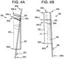
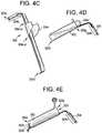
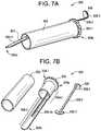
- an access devicecan include an access tube having an upper portion adjacent to a proximal end, a lower portion adjacent to a distal end, a curved elbow portion therebetween connecting the upper portion to the lower portion, and a working channel formed through the access tube from the distal end to the proximal end; and an inner blade disposed through the access tube of the access device, the inner blade being configured to apply a radially outward force on an obstacle to retract the obstacle in a radially outward direction to create an obstacle free area, wherein the inner blade includes: a first cylindrical portion having an outer circumference smaller than the circumference of the working channel at the proximal end of the access tube, such that the first cylindrical portion can slide within the working channel, a first blade portion connected to a distal end of the first cylindrical portion and extending longitudinally in a distal direction therefrom, and a second blade portion connected to the distal end of the first blade portion and extending longitudinally in a distal direction therefrom, the second blade portion having a distal end
- the first blade portion and the second blade portioncan be biased to a resting position in which the first blade portion and the second blade portion are at their outermost radial positions relative to a central longitudinal axis of the working channel.
- the curved elbow portion of the access tubecan include an inside curve and an outside curve formed at diametrically opposed ends of the access tube, the inside curve having a shorter length than a length of the outside curve of the curved elbow portion.
- the curved elbow portioncan be configured such that (i) the working channel at the upper portion is not coaxial with the working channel at the lower portion, and (ii) an inner surface of the access tube is not a continuous flat surface in a longitudinal direction from the proximal end to the distal end of the access tube.
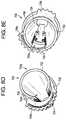
- Rotating the inner blade in a first direction relative to the access tubecan cause an outer surface of the first blade portion to contact the outside curve of the curved elbow, causing at least a portion of the first blade portion and at least the distal end of the second blade portion to move radially inward toward the central longitudinal axis of the working channel.
- Rotating the inner blade in a second direction opposite the first direction relative to the access tubecan cause the outer surface of the first blade portion to contact the inside curve of the curved elbow, causing at least a portion of the first blade portion and at least the distal end of the second blade portion to move radially outward away from the central longitudinal axis of the working channel.
- the first blade portioncan be longitudinally parallel to the inner surface of the access tube when the first blade portion is at its biased and outermost radial position.
- a surgical methodcan include inserting an access tube of an access device into a patient; positioning an inner blade through a working channel of the access tube in a first position in which: (i) a distal end of the inner blade is disposed radially inward toward a central longitudinal axis of the working channel; (ii) the distal end of the inner blade protrudes from a distal end of the working channel; (iii) an outer surface of the inner blade is disposed adjacent to tissue of the patient to be retracted, and (iv) the outer surface of a first blade portion of the inner blade is at least partially in contact with an outside curve of a curved elbow portion of the access tube, thereby causing a portion of an inner surface of the access tube to apply a radially inward force on the first blade portion; and rotating the inner blade relative to the access tube, from the first position to a second position in which the outer surface of the first blade portion of the inner blade is at least partially in contact with an inside curve of the curved elbow portion of the
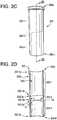
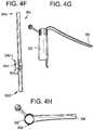
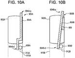
- an access devicecan include an outer tube having a distal end, a proximal end, and a working channel formed therethrough; and an inner shield disposed through the outer tube such that a distal end of the inner shield protrudes from the distal end of the outer tube, wherein the inner shield is movable relative to the outer tube between a first position, in which a distal end of a blade of the inner shield is disposed in a radially inward position, and a second position, in which the distal end of the blade of the inner shield is disposed in a radially outward position, and wherein the inner shield is movable between the first position and the second position based on an amount of force applied upon a slotted cylinder of the inner shield by an inner surface of the outer tube, the force being configured to control the compression of the slotted cylinder about its circumference.
- the blade of the inner shieldcan have a length larger than a length of the outer tube, the blade having at least a distal portion adjacent to the distal end of the blade, the distal portion of the blade being configured to retract an obstacle in a radially outward direction.
- the slotted cylinder(i) can be attached to the blade, (ii) can be a cylindrical structure having a slot extending from a distal end to a proximal end of the slotted cylinder, and a slotted cylinder opening formed therethrough, (iii) can have an angled distal-facing surface such that a portion of the distal-facing surface of the slotted cylinder that contacts the blade forms an angle larger than 90 degrees with the blade, and (iv) can be formed of a resilient material that allows for its circumferential compression by the inner surface of the outer tube.
- the length of a portion of the blade that extends distally from the distal-facing surface of the slotted cylindercan be larger than the length of the outer tube, such that the distal end of the blade protrudes through the outer tube opening at the distal end of the outer tube.
- a circumference of the slotted cylinder in the first positioncan be larger than the circumference of the opening of the outer tube at the proximal end of the outer tube.
- the circumference of the slotted cylinder in the second positioncan be smaller than the circumference of the opening of the outer tube.
- the bladecan be made of a malleable material, such that the length of the handle portion can be adjusted to a desired size.
- a surgical methodcan include inserting an access tube of an access device into a patient; positioning an inner shield through a working channel of the access tube in a first position in which a distal portion of a slotted cylinder of the inner shield is inserted through the working channel of the access tube at a proximal end of the access tube, such that an outer surface of the slotted cylinder is not parallel to an inner surface of the access tube, thereby causing a distal end of the inner shield to be disposed radially inward toward a central longitudinal axis of the working channel and an outer surface of the inner shield to be disposed adjacent to tissue of the patient to be retracted; and moving the inner shield from the first position to the second position by distally sliding the inner shield through the working channel such that the slotted cylinder is inserted within the working channel, thereby causing: (i) the inner surface of the access tube to compress the slotted cylinder about its circumference, (ii) the distal end of the inner shield to retract radially outward away from the
- Compressing of the slotted cylinder about its circumferencecan cause (i) the outer surface of the slotted cylinder to contact the inner surface of the access tube and to be parallel thereto, and (ii) the distal end of the inner shield to retract radially outward.
- the methodcan include rotating the inner shield relative to the access tube while the inner shield is in the second position, such that a different portion of the tissue is retracted radially outward.
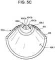
- an access devicecan include an outer tube having a distal end, a proximal end, and a working channel formed therethrough; a shield having a shield opening formed therethrough, and being configured to slide through the working channel, the shield including (a) a constant portion adjacent to a proximal end of the shield, and (b) an expandable portion adjacent to a distal end of the shield, the expandable portion including one or more arms extending distally at a radially inward angle, the arms being movable between a biased, first position in which a distal end of the arms is disposed in a radially inward direction, and a second position in which the distal end of the arms is moved in a radially outward direction; and an inner tube having an inner tube opening formed therethrough and being configured to slide within the shield opening, the inner tube comprising (a) a constant portion adjacent to a proximal end of the inner tube, and (b) an expander portion adjacent to a distal end of the inner tube and
- the expander portion of the inner tubecan be configured to slide within the shield opening at the expandable portion, thereby causing the arms to deflect from the first position to the second position. At least a portion of the expandable portion of the shield and at least a portion of the expander portion of the inner tube can protrude through the working channel at the distal end of the outer tube.
- One or more of the shield and the inner tubecan be partial cylinders.
- the outer tubecan include slots formed on an inner surface of the outer tube that are configured to receive the shield and the inner tube, thereby preventing the rotation of the shield and the inner tube relative to the outer tube when the shield and the inner tube are disposed within the working channel.
- a surgical methodcan include inserting an access tube of an access device into a patient; positioning a shield through a working channel of the access tube in a first position, in which arms of the shield protrude through a distal end of the access tube and are angled radially inward toward a central longitudinal axis of the working channel; and moving the shield from the first position to a second position, by distally advancing an inner tube through a shield opening formed between a proximal end and a distal end of the shield such that an outer surface of the distal end applies a radially outward force on the inner surface of the arms of the shield, thereby causing the arms of the shield to deflect radially outward.
- the armscan gradually deflect radially outward in the radially outward direction as the expander portion is gradually advanced distally within the shield opening at the expandable portion of the middle tube.
- an access devicecan include an outer tube having a distal end, a proximal end, and a working channel formed therethrough; a shield including a longitudinal body and a flexible arm extending distally therefrom and protruding through a distal end of the working channel, the shield being movable between a first position, in which the flexible arm is disposed radially inward, and a second position, in which the flexible arm is disposed radially outward; and an expander including a longitudinal body slidably engaged with the shield in a longitudinal direction, the expander being configured to move the shield between the first and second positions by translating the expander longitudinally relative to the shield.
- the shieldcan include a plurality of pins protruding from an outer surface of the longitudinal body of the shield.
- the shieldcan be removably fixed to the access tube by inserting the plurality of pins into respective keyholes of the outer tube and sliding the pins distally and proximally along corresponding slotted tracks of the outer tube into the removably fixed position.
- a surgical methodcan include inserting an access tube of an access device into a patient; positioning a shield through a working channel of the access tube in a first position, in which a flexible arm of the shield protrudes through a distal end of the access tube and is angled radially inward toward a central longitudinal axis of the working channel; and moving the shield from the first position to a second position, by distally advancing an expander through the working channel of the access tube, relative to the shield, such that the expander portion contacts at least a portion of the flexible arm of the shield, thereby causing the shield to move radially outward.
- the flexible armcan gradually move toward the second position as an increasing length of the expander portion is in contact with the flexible arm of the shield by the distal advancement of the expander portion.
- an access devicecan include an outer tube having a distal end, a proximal end, and a working channel formed therethrough; a shield being configured to slide through the working channel and extending longitudinally such that a distal end of the shield protrudes through the working channel at the distal end of the outer tube, the shield having a longitudinal slot formed through an inner and outer surface of the shield and extending distally from a proximal end of the of the shield, wherein the shield is movable from a first position in which a distal end of the shield is disposed radially inward, and a second position in which the distal end of the arm is moved in a radially outward direction; and
- a wedgeincluding a blade portion and a wedging tip formed at a distal end of the wedge, the wedge being positioned relative to the shield such that (i) a proximal end of the wedge is positioned at the inner surface of the shield, (ii) the blade portion penetrates through the longitudinal slot of the shield, and (iii) the wedging tip is positioned at the outer surface of the shield.
- the wedging tipcan have a width larger than the width of the longitudinal slot.
- the blade portion of the wedgecan have a width smaller than the width of the longitudinal slot.
- the wedging tipcan be slidably disposed between the obstacle shield and the access tube.
- the shieldcan be formed of a material that enables at least a portion of the obstacle shield at its distal end to move in a radially inward direction.
- a surgical methodcan include inserting an access tube of an access device into a patient; positioning a shield through a working channel of the access tube in a first position, in which a distal end of the shield protrudes through a distal end of the access tube and is angled radially inward toward a central longitudinal axis of the working channel; and moving the shield from the first position to a second position, by proximally retracting a wedge relative to the shield such that a distal end of the shield slides between the shield and the access tube, thereby causing a force to be applied on the outer surface of the shield and the distal end of the shield to move in a radially outward direction.
- an access devicecan include an outer tube having a distal end, a proximal end, a working channel formed therethrough, and a longitudinal slot extending distally from the proximal end, the longitudinal slot penetrating through an inner surface and an outer surface of the outer tube; a shield including a longitudinal body and a pin protruding from a proximal end of the shield, the shield being disposed through the longitudinal slot of the outer tube such that the proximal end of the shield is positioned external to the outer surface of the outer tube and the distal end of the shield is positioned internal to the inner surface of the outer tube; and a cam mechanism having a cam opening formed therethrough, through which the outer tube is disposed, the cam mechanism further including a circumferential slot formed through a proximal-facing surface and a distal-facing surface of the cam mechanism, the circumferential slot being configured to receive the pin of the shield and having an increasing radius relative to a center of the cam opening such that one end the shield is positioned further
- Rotation of the cam mechanism relative to the outer tubecan cause the pin of the shield to slide along the circumferential slot of the cam mechanism.
- the circumferential slotcan be formed around less than the entire circumference of the cam mechanism.
- the distal portion of the shieldcan move in a radially inward direction as the pin is driven in a radially outward direction by the circumferential slot of the cam mechanism.
- the shieldcan pivot about a portion of the outer tube along the longitudinal slot, causing the movement of the distal portion of the shield in the radially inward direction.
- a surgical methodcan include inserting an access tube of an access device into a patient; disposing a shield in a first position, in which a distal end of the shield is positioned radially inward toward a central longitudinal axis of a working channel of the access tube; and moving the shield from the first position to a second position, by rotating a cam mechanism relative to the outer tube such that a pin of the shield is driven along a circumferential slot of the cam mechanism, from a first end to a second end, the second end being positioned further from the center of the cam opening than the first end such that (i) the proximal end of the shield is moved in the radially outward direction, (ii) the distal end of the shield is moved in the radially inward direction, and (iii) the shield pivots about a longitudinal slot formed in the access tube.
- the cam mechanismcan be rotated counterclockwise to drive the pin of the shield from the first end to the second end of the circumferential slot.
- the cam mechanismcan be rotated clockwise to drive the pin of the shield from the second end to the first end of the circumferential slot.
- an access devicecan include an outer tube having a distal end, a proximal end, and a working channel formed therethrough; and a shield being having a longitudinal body, a handle portion formed at a proximal end of the longitudinal body, the handle portion curving or bending away from the longitudinal body, and a finger portion connected to a distal-facing surface of the handle portion and extending distally, the finger portion being curved or bent based on the curvature or degree of bending of the handle, wherein the shield is movable between a first position, in which the shield is disposed in a radially outward position, and a second position, in which the shield is moved toward a central longitudinal axis of the working channel.
- the finger portioncan be connected to the inferior surface of the handle portion at a region of the handle away from a proximal end of the handle portion.
- a surgical methodcan include inserting an access tube of an access device into a patient; positioning a shield through a working channel of the access tube in a first position in which a distal force is applied on a proximal-facing surface of a handle portion of the shield, such that a distal end of a longitudinal body of the shield and a distal end of a finger portion of the shield are caused to move in a radially inward direction; and relaxing the distal force to move the shield from the first position to a second position in which the distal end of the shield is retracted in a radially outward direction relative to the radially inward position of the distal end of the shield in the first position.
- Relaxing the distal force applied on the proximal-facing surface of the handle portioncan cause the longitudinal body and the handle portion of the shield to be retracted to their biased position.
- FIG. 1is a diagram illustrating the retraction of nerve tissue from surgical safe areas
- FIG. 2Ais a side view of one exemplary embodiment of an obstacle retracting access device
- FIG. 2Bis cross-sectional side view of the access device of FIG. 2A taken along the line A-A;
- FIG. 2Cis a side view of an exemplary embodiment of an access tube of the access device of FIG. 2A ;
- FIG. 2Dis a cross-sectional side view of the access tube of FIG. 2C taken along the line B-B;
- FIG. 2Eis a sectional side view of an exemplary embodiment of an access tube of the access device of FIG. 2A ;
- FIG. 2Fis a sectional side view of an exemplary embodiment of an access tube of the access device of FIG. 2A ;
- FIG. 2Gis a perspective view of an exemplary embodiment of an access tube of the access device of FIG. 2A ;
- FIG. 2His another perspective view of the access tube of FIG. 2G ;
- FIG. 3Ais a side view of an exemplary embodiment of an inner blade of the access device of FIG. 2A ;
- FIG. 3Bis a cross-sectional view of an exemplary embodiment of an inner blade and an access tube of the access device of FIG. 2A ;
- FIG. 3Cis a sectional side view of the access device of FIG. 2A with an inner blade thereof in a radially inward position;
- FIG. 3Dis a sectional side view of the access device of FIG. 2A with an inner blade thereof in a radially outward position;
- FIG. 3Eis a top view of an exemplary embodiment of an access device in a radially inward configuration
- FIG. 3Fis a top view of the access device of FIG. 3E in a radially outward configuration
- FIG. 3Gis a top view of an exemplary embodiment of an access device in a radially inward configuration
- FIG. 3His a top view of the access device of FIG. 3G in a radially outward configuration
- FIG. 4Ais a sectional side view of another exemplary embodiment of an obstacle retracting access device in a radially inward configuration
- FIG. 4Bis a sectional side view of the access device of FIG. 4A in a radially outward configuration
- FIG. 4Cis a perspective view of an exemplary embodiment of a shield of the access device of FIG. 4A ;
- FIG. 4Dis a sectional side view of another exemplary embodiment of an obstacle retracting access device in a radially inward configuration
- FIG. 4Eis a sectional side view of the access device of FIG. 4D in a radially outward configuration
- FIG. 4Fis a perspective view of an exemplary embodiment of a shield
- FIG. 4Gis a side view of an exemplary embodiment of an obstacle retracting access device
- FIG. 4His a top view of the access device of FIG. 4G ;
- FIG. 5Ais a perspective view of another exemplary embodiment of an obstacle retracting access device
- FIG. 5Bis a sectional perspective view of the access device of FIG. 5A taken along the line C-C;
- FIG. 5Cis a sectional perspective view of the access device of FIG. 5A taken along the line D-D;
- FIG. 5Dis a side view of the access device of FIG. 5A , unassembled;
- FIG. 5Eis a side view of the distal end of the access device of FIG. 5D having an inserted middle tube in a radially inward configuration
- FIG. 5Fis a top view of the access device of FIG. 5E ;
- FIG. 5Gis a diagram illustrating the top view of the access device of FIG. 5F ;
- FIG. 5His a side view of the distal end of the access device of FIG. 5D having inserted middle and inner tubes;
- FIG. 5Iis a top view of the access device of FIG. 5H ;
- FIG. 5Jis a diagram illustrating the top view of the access device of FIG. 5I ;
- FIG. 6Ais a sectional side view of another exemplary embodiment of an obstacle retracting access device
- FIG. 6Bis a perspective view of the access device of FIG. 6A ;
- FIG. 7Ais a perspective view of another exemplary embodiment of an obstacle retracting access device
- FIG. 7Bis a perspective view of the access device of FIG. 7A , unassembled.
- FIG. 7Cis a perspective view of an exemplary embodiment of a shield of the access device of FIG. 7A ;
- FIG. 7Dis a side view of the shield of FIG. 7C ;
- FIG. 7E and FIG. 7Fare diagrams illustrating moving the access device of FIG. 7A between a radially outward configuration and a radially inward configuration
- FIG. 8Ais a perspective view of another exemplary embodiment of an obstacle retracting access device
- FIG. 8Bis a side view of the access device of FIG. 8A ;
- FIG. 8Cis a sectional side view of the access device of FIG. 8B taken along the line E-E;
- FIG. 8Dis a perspective view of the proximal end of the access device of FIG. 8A ;
- FIG. 8Eis another perspective view of the proximal end of the access device of FIG. 8A ;
- FIG. 8Fis a diagram illustrating a top view of the access device of FIG. 8A in a radially-outward configuration
- FIG. 8Gis a diagram illustrating a side view of an access tube and shield of the access device of FIG. 8F ;
- FIG. 8His a diagram illustrating a top view of the access device of FIG. 8A in a radially-inward configuration
- FIG. 8Iis a diagram illustrating a side view of an access tube and shield of the access device of FIG. 8H ;
- FIG. 8Jis a diagram illustrating a top view of the access device of FIG. 8A in a radially-inward and longitudinally-advanced configuration
- FIG. 8Kis a diagram illustrating a side view of an access tube and shield of the access device of FIG. 8J ;
- FIG. 8Lis a diagram illustrating a top view of the access device of FIG. 8A in a radially-outward and longitudinally-advanced configuration
- FIG. 8Mis a diagram illustrating a side view of an access tube and shield of the access device of FIG. 8L ;
- FIG. 9Ais a sectional side view of another exemplary embodiment of an obstacle retracing access device.
- FIG. 9Bis a perspective view of an exemplary embodiment of a shield of the access device of FIG. 9A ;
- FIG. 9Cis another perspective view of the shield of FIG. 9B ;
- FIG. 10Ais a sectional side view of another exemplary embodiment of an obstacle retracing access device having an offset nerve shield.
- FIG. 10Bis a sectional side view of another exemplary embodiment of an obstacle retracing access device having an offset nerve shield.
- a surgical access devicecan include an outer tube that defines a working channel through which a surgical procedure can be performed.
- a shield, blade, arm, or other structurecan be manipulated with respect to the outer tube to retract an obstacle.
- an inner bladecan protrude from a distal end of the outer tube to retract obstacles disposed distal to the outer tube.
- the inner bladecan be movable between a radially-inward position and a radially-outward position.
- the radially-inward positioncan allow insertion of the blade to the depth of the obstacle to position the obstacle adjacent to and radially-outward from the blade. Subsequent movement of the blade to the radially-outward position can retract the obstacle in a radially-outward direction.
- the bladecan be manipulated remotely, e.g., from a proximal end of the access device or a location disposed outside of the patient.
- the bladecan be manipulated in various ways, such as by rotating the blade relative to the outer tube, translating the blade longitudinally relative to the outer tube, sliding an expander along the blade, driving a wedge between the blade and the outer tube, actuating a cam mechanism of the access device, and/or pivoting the blade relative to the outer tube.
- the present disclosureincludes some illustrations and descriptions that include prototypes or bench models. A person skilled in the art will recognize how to rely upon the present disclosure to integrate the techniques, devices, and methods provided for into a product, such as a consumer ready, warehouse-ready, or operating room ready surgical device.
- Exemplary embodiments of the present disclosureprovide access devices, and more specifically, access devices such as surgical access devices configured to retract obstacles such as nerve tissue to create safe surgical areas.
- An access devicecan include an access tube and one or more obstacle retraction components.
- an access devicecan include an outer access tube and an inner shield or blade disposed within the access tube for retracting tissue.
- the one or more retraction componentscan be configured to engage with each other and/or with the access tube to cause radial movement of obstacles in an inward and/or outward direction relative to an opening or working channel of the access tube.
- the access tube openingcan be formed through the body of the access tube, extending through the distal and proximal ends of the access tube, and can be configured to receive a retraction component.
- the retraction componentcan be or can include a shield or blade.
- the retraction componentcan have a sufficient length so as to protrude at least in part from the distal end of the access tube.
- the retraction componentcan be configured to apply a radially-directed force on the obstacle to be moved.
- radial movement of the obstacle to create a safe areais achieved by inserting the access device into a patient in the direction of a target surgical area. While the retraction component of the access device is in a position in which the distal end of the retraction component is disposed radially inward, the access device is advanced distally such that the distal end of the retraction component is positioned (1) at or beyond the depth of the obstacle to be moved, and (2) radially-inward from the obstacle. The retraction component is then manipulated to move the distal end of the retraction component in a radially outward direction.
- the radially outward movement of the distal end of the retraction componentcauses an outer surface of the retraction component to apply a radially outward force on the obstacle, moving it away from a central longitudinal axis of the access tube or a working channel thereof.
- the surgical safe areawhich can be concentric with the opening of the access tube, is thereby expanded such that its outside border or circumference corresponds to the radially outward position of the distal end of the retraction component and/or the obstacle. Operating within an expanded surgical safe area is thus enabled.
- the position of the retraction componentcan be fixed such that the obstacle can be maintained in a retracted position without requiring further manipulation thereof, e.g., in a “hands free” manner.
- the access tubes and retraction components described hereincan have any shape, dimension and/or or other characteristics. Moreover, the shape, dimension and/or other characteristics of the access tubes and retraction components can vary within a single access tube or component. For instance, the diameter of an access tube at a proximal end can be different than the diameter of the access tube at a distal end, such that the access tube narrows from one end to the other. It should also be understood that while cylindrical access tubes having round openings are generally described herein, the access tubes can have square, triangular, oval, elliptical, or any other shaped openings. Access tubes can include cannulas, multi-blade or slotted retractors, and the like.
- the shape, dimension and/or other characteristics of the access tubes and retraction componentscan vary based on the shape, dimension and/or characteristics of other of the access tubes and retraction components with which they engage.
- a retraction componentcan have a curved body corresponding to the curvature of the access tube, such that when the retraction component is disposed within the access tube and in contact with an inner surface of the access tube, the retraction component can make intimate contact with the inner surface.
- an access device with one or more retraction componentscan be used to retract a nerve away from a safe area, thereby enlarging the safe area or providing safer access to the safe area.
- Area 101 - 1 and 101 - 2represent a surgical working area in a patient's body, as viewed from a top-down or outside-in perspective through an access tube inserted into the patient's body.
- Working area 101 - 1is the area having a nerve running therethrough while working area 101 - 2 is the area having the same nerve 108 - 1 and 108 - 2 retracted therefrom.
- FIGS. 2A to 2Hillustrate one exemplary embodiment of a surgical access device 200 configured to radially move nerve tissue and other obstacles, to provide enhanced surgical access. Described in connection with FIGS. 2A to 2H are examples of the surgical access device 200 having multiple retraction components, e.g., multiple blades 204 . On the other hand, described in connection with FIGS. 3A to 3H (collectively referred to as “ FIG. 3 ”) are examples of the surgical access device 200 including only a single retraction component, e.g., a single blade 204 . It should be understood that descriptions of embodiments in which the surgical access device includes a single blade can similarly be applied to and/or function with surgical access devices having multiple blades, and that the access device can include any number of blades.
- the surgical access device 200is used during surgery to move nerve tissue radially outward, in order to protect or shield the nerve tissue and allow a safe surgical area within the patient's body to be safely accessed or enlarged.
- the surgical access device 200can include an outer access tube 202 and one or more inner blades 204 (also referred to herein as “inner shield”).
- the access tubecan include a body having a cylindrical exterior surface and a non-cylindrical interior surface.
- the access tubecan extend between proximal and distal ends 202 p , 202 d .
- the access tubecan include an opening or hole formed therethrough, through its proximal end 202 p its distal end 202 d , to define a working channel.
- the access tube 202can have a closed circumference or perimeter.
- the access tube 202can have an inner surface 202 i and an outer surface 202 o .
- the inner surface 202 ican define the opening or working channel through the access tube 202 , extending through proximal end 202 p and the distal end 202 d . It should be understood that portions of the body of the access tube 202 , including its inner and outer surfaces 202 i and 202 o , can also be referred to as its walls.
- the access tube 202can include two cylindrical or tubular portions: an upper portion 202 - 1 extending distally from the proximal end 202 p , and a lower portion 202 - 2 extending proximally from the distal end 202 d , which are joined by an elbow or elbow portion 202 - 3 .
- the access tube 202can be a single, cohesive or monolithic unit. In other words, the access tube 202 can be manufactured as a single access tube.
- the portions 202 - 1 , 202 - 2 and 202 - 3can be provided separately (e.g., distinctly manufactured) and later combined, joined, attached, welded, or the like into the access tube 202 .
- Portions 202 - 1 and 202 - 2can each have respective proximal and distal ends 202 - 1 p and 202 - 1 d , and 202 - 2 p and 202 - 2 d .
- the portions 202 - 1 and 202 - 2can be connected to each other at or via the elbow 202 - 3 .
- the distal end 202 - 1 d of the upper portion 202 - 1can connect to a proximal end 202 - 3 p of the elbow, and the proximal end 202 - 2 p of the lower portion 202 - 2 can connect to a distal end 202 - 3 d of the elbow 202 - 3 .
- An elbow on the access tube 202refers to a portion at which the outer surface 202 o and/or the inner surface 202 i of the access tube 202 does not form a continuous flat or cylindrical surface along its length (e.g., along a longitudinal or proximal-distal direction), resembling the shape of a bent human elbow. That is, the upper and lower portions 202 - 1 and 202 - 2 of the access tube 202 can be non-coaxial with one another.
- a central longitudinal axis of the portion of the working channel defined in the upper portion 202 - 1 of the access tube 202can extend at an oblique angle with respect to a central longitudinal axis of the portion of the working channel defined in the lower portion 202 - 2 .
- the working channel of the access tube 202can thereby define an inside curve C i and an outside curve C o .
- the inside and outside curves C i and C ocan be positioned at the same or substantially similar lengthwise positions of the access tube 202 .
- the inside and outside curves C i and C ocan be positioned at diametrically opposed sides of the access tube 202 .
- the inside and outside curves C i and C ocan be curved such that they are convex and concave, respectively.
- the length and degree of curvature of the inside and outside curves C i and C ocan vary as deemed optimal or necessary.
- the inside curve C ican have a length and/or degree of curvature that is smaller than the length and/or degree of curvature of the outside curve C o .
- the inside and outside curves C i and C ocan be formed such that, when an inner blade is in a position in which its proximal end is disposed along the inner surface of the inside curve C i , its remaining length is disposed in contact or proximate to the inner surface of the access tube 202 , such that a distal end of the blade is disposed in a radially-outward position.
- the inner bladewhen the inner blade is in another position in which its proximal end is disposed along the inner surface of the outside curve C o , its remaining length is disposed away from the inner surface of the access tube, such that a distal end of the blade is disposed in a radially-inward position.
- the upper portion 202 - 1can be angled relative to the lower portion 202 - 2 . More specifically, as illustrated in FIG. 2E , the access tube 202 can have a longitudinal axis L 1 that is the same as the central longitudinal axis L C1 of the lower portion 202 - 2 running in a distal-proximal direction along the center of the opening formed through the lower portion 202 - 2 .
- the upper portion 202 - 1can have a central longitudinal axis L C2 running in a distal-proximal direction along the center of the opening formed through the upper portion 202 - 1 .
- the upper portion 202 - 1can be angled such that an angle at formed by the central longitudinal axes L C1 and L C2 is not equal to 180 degrees. In some embodiments, the angle at is an oblique angle or an angle greater than 0 degrees.
- FIG. 2Falso illustrates the angling of the upper and lower portions 202 - 1 and 202 - 2 relative to the central longitudinal axes L C1 and L C2 of the lower portion 202 - 2 and the upper portion 202 - 1 , respectively.
- such angling of the upper and/or lower portions 202 - 1 and 202 - 2can enable an inner blade 204 to be activated (e.g., deflected, bent, deformed, moved, etc.) in order to retract or radially move nerve tissue or other obstacles.
- the access tube 202 and/or its upper and lower portions 202 - 1 and 202 - 2can have openings of various diameters, for instance, as deemed necessary or optimal to access certain target regions in a patient's body, enable the insertion of various instruments or devices therethrough, and so forth.
- the diameter of the openings of the upper and lower portions 202 - 1 and 202 - 2can be different from each other.
- the opening of the upper portion 202 - 1can have a larger diameter than the opening of the lower portion 202 - 2 .
- the opening formed through the access tube 202can be configured to receive an inner blade 204 that is used to radially move or retract nerve tissue or the like at or proximal to its distal end. More specifically, as illustrated, the inner blade 204 can include a proximal end 204 p and a distal end 204 d . As shown in FIG.
- the inner blade 204can include the following portions, which are listed in their order from the proximal end 204 p to the distal end 204 d : a first cylindrical portion 204 - 1 , a second cylindrical portion 204 - 2 connected to the first cylindrical portion 204 - 1 , a first blade portion 204 - 3 and second blade portion 204 - 4 connected to the first blade portion 204 - 3 . It should be understood that, although they are independently described, the portions 204 - 1 to 204 - 4 can be sections of a single, cohesive or monolithic inner blade 204 .
- the first cylindrical portion 204 - 1can extend distally from the proximal end 204 p of the inner blade 204
- the second cylindrical portion 204 - 2can extend distally from the first cylindrical portion 204 - 1
- the first and second cylindrical portions 204 - 1 and 204 - 2can have a shape matching or similar to that of the access tube 202 . That is, the degree of curvature of the first and/or second cylindrical portions 204 - 1 and 204 - 2 can be the same or substantially similar to that of the access tube 202 .
- the first and second cylindrical portions 204 - 1 and 204 - 2can be coaxial with one another.
- the first cylindrical portion 204 - 1can have a diameter and/or circumference formed by its outer surface that is larger than the diameter and/or circumference formed by the outer surface of the second cylindrical portion 204 - 2 .
- the diameter and/or circumference formed by the outer surface of the second cylindrical portion 204 - 2can be the same or substantially similar to the diameter and/or circumference formed by inner surfaces (e.g., openings) of the upper and/or lower portions 202 - 1 and 202 - 2 of the surgical access device 202 , such that when the second cylindrical portion 204 - 2 is inserted therein, the outer surface of the second cylindrical portion 204 - 2 makes continuous contact (or is placed substantially closely in contact) with the inner surface of the upper and/or lower portions 202 - 1 and 202 - 2 .
- a lipcan be formed at an area where the first cylindrical portion 204 - 1 meets the second cylindrical portion 204 - 2 .
- the lipcan be configured to prevent distal movement of the inner blade 204 therebeyond, such that the second cylindrical portion 204 - 2 can be inserted and slid within the opening of the surgical access device while the first cylindrical portion 204 - 1 is prevented from such insertion within the opening of the access tube 202 .
- the lipcan engage with the distal end of the access tube 202 and prevent distal movement of the inner blade 204 relative to the access tube 202 .
- the lipcan be formed such that it is perpendicular with the outer surface of the inner blade 204 (e.g., forming a 90 degree angle) or angled a sufficiently small degree (e.g., more than 90 degrees and less than 180 degrees) such that the lip can indeed prevent insertion of the first cylindrical portion 204 - 1 within the opening of the access tube 202 .
- the proximal end of the first blade portion 204 - 3can be formed on or attached to the distal end of the second cylindrical portion 204 - 2 .
- the first blade portion 204 - 3can extend longitudinally toward the distal end of the inner blade 204 .
- the surface of the first blade portion 204 - 3can be curved or arc-shaped, and can have a degree of curvature matching or substantially similar to that of the second cylindrical portion 204 - 2 and/or the upper portion 202 - 1 of the access tube 202 .
- the length of the curve of the first blade portion 204 - 3e.g., the width of the first blade portion, can vary and can be determined based on various factors including the size of the nerve tissue or other obstacle to be moved.
- the first blade portion 204 - 3can have a surface that forms a partial circle or cylinder, similar to the cylindrical portions 204 - 1 and 204 - 2 .
- the length of the first blade portion 204 - 3can vary and can be determined based on various factors, including the intended use, target area to be inserted, target nerve tissue or obstacle to be moved, and so forth.
- the length of the first blade portion 204 - 3can be selected such that, when the inner blade 204 is fully inserted into the opening of the access tube 202 , the distal end of the first blade portion reaches or approximates the distal end of the lower portion 202 - 2 , and/or protrudes therefrom.
- the outside surface of the first blade portion 204 - 3is in contact with or substantially proximate to the inside surface of the upper portion 202 - 1 .
- the proximal end of the second blade portion 204 - 4can be formed on or attached to the distal end of the first blade portion 204 - 3 .
- the second blade portion 204 - 4can be curved or can have an arc-shape with a degree of curvature matching, based on, or substantially similar to that of the second cylindrical portion 204 - 2 , the lower portion 202 - 2 , and/or the first blade portion 204 - 3 .
- the thickness of the body of the second blade portion 204 - 4as measured by the material between the inner and outer surfaces thereof, can be larger than the thickness of the first blade portion 204 - 3 .
- the length of the second blade portion 204 - 4can be based on various factors described above.
- the length of the second blade portion 204 - 4can be sufficiently long to protrude from the distal end of the access tube 202 and/or reach nerve tissue or other obstacles to be retracted or moved.
- the second blade portion 204 - 4can extend longitudinally at an angle different than that of the first blade portion 204 - 3 . That is, as described above, the first blade portion 204 - 3 can extend parallel to the longitudinal direction of the inner surface of the upper portion 202 - 1 of the access tube 202 , such that the outer surface of the first blade portion 204 - 3 is in contact with or is substantially proximate to the inner surface of the upper portion 202 - 1 .
- the area where the first blade portion 204 - 3 meets the second blade portion 204 - 4can form an oblique angle.
- the blade 204 or a portion thereofcan be or can include a spring arm.
- the blade 204 or a portion thereofcan be formed from a flexible and resilient material such that the first and second blade portions 204 - 3 and 204 - 4 are biased to a default, resting position.
- the resting positioncan be one in which the second blade portion 204 - 4 is disposed in a radially outward position.
- operating or engaging with the inner blade 204 when disposed within the opening of the surgical access tube 202can cause the inner surface of the upper and/or lower portions 202 - 1 and 202 - 2 to apply force (e.g., a radially inward force) against the bias of the blade 204 to cause the first blade portion and/or the second blade portion 204 - 3 and 204 - 4 to move radially inward.
- forcee.g., a radially inward force
- the first blade portion 204 - 3 and/or the second blade portion 204 - 4can return towards their resting, radially-outward position.
- the inner blade 204can be inserted into the access tube 202 , through the opening formed through the upper and lower portions 202 - 1 and 202 - 2 . It should be understood that the inner blade 204 can be inserted prior to the upper and lower portions 202 - 1 and 202 - 2 being inserted into a patient's body and positioned at the target area, or can later be inserted once the upper and lower portions 202 - 1 and 202 - 2 have been properly arranged at the target surgical area.
- the inner blade 204can be inserted through the opening of the upper and lower portions 202 - 1 and 202 - 2 such that the first and second blade portions 204 - 3 and 204 - 4 are in a first position or configuration. In a first position or configuration, the inner blade 204 and/or its first and second blade portions 204 - 3 and 204 - 4 are aligned with, or disposed on or along or in contact with the outer curve C o of the elbow 202 - 3 of the access tube 202 , as shown in FIG. 3C .
- the inner surfaces of the upper and/or lower portions 202 - 1 and 202 - 2(and/or the elbow 202 - 3 ) apply a radially inward force against the outer surfaces of the first and/or second blade portions 204 - 3 and 204 - 4 , such that the distal end of the second blade portion 204 - 4 is caused to flex or move radially inward, toward the central longitudinal axis L C1 of the lower portion 202 - 2 .
- the radially inward force applied against the outer surfaces of the first and/or second blade portions when in the first positioncan be due to the angling of the inner surface of the first and second portions 202 - 1 and 202 - 2 described above.
- the radially inward disposition of the distal end of the second blade portion 204 - 4can enable the access tube 202 and/or its inner blade 204 to be more safely moved distally toward a target surgical area where a nerve tissue or other obstacle 206 is positioned, e.g., during initial positioning of the access device.
- the access tube 202 and/or the inner blade 204can be positioned such that, in the first position of the inner blade, the nerve tissue 206 or other obstacle is disposed radially outward from the outer surface of the second blade portion 204 - 4 .
- the access device 200can be actuated in order to retract (e.g., move radially outward) the nerve tissue 206 , as shown in FIG. 3D .
- the inner blade 204can be rotated relative to the access tube 202 , e.g., about the axis L C2 , to a second position. Such rotation can cause the inner blade and/or its first and second blade portions 204 - 3 and 204 - 4 to be aligned with, or disposed on or along or in contact with the inner curve C i of the elbow 202 - 3 of the access tube 202 .
- the access tube 202 and/or the inner blade 204can be configured such that they can be rotated clockwise and/or counterclockwise with respect to one another.
- the blade 204When aligned with the inner curve C i , the blade 204 can be allowed to return towards its resting state, thereby moving the distal end of the blade and, by extension, a nerve or other obstacle in contact with an outer surface thereof, in a radially outward direction.
- the angling of the upper and lower portions 202 - 1 and 202 - 2 , the shape of the elbow 202 - 3 , and/or the angling of the portions of the inner blade 204can be configured to cause the force from the inner surface of the upper and lower portions 202 - 1 and 202 - 2 , and/or of the elbow 202 - 3 , to be reduced or eliminated when the inner blade 204 is in the second position or configuration, such that the first and second blade portions 204 - 3 and 204 - 4 return to their biased positions and away from the central longitudinal axis L C1 , as shown in FIG. 3D .
- the first and/or second blade portions 204 - 3 and 204 - 4move radially outward, such that the nerve tissue 206 positioned adjacent to the second blade portion 204 - 4 is retracted in a radially outward direction, thereby positioning the nerve tissue in a safer location, shielded by the second blade portion 204 - 4 and/or away from the central longitudinal axis L C2 of the lower portion 202 - 2 .
- the distal end of the second blade portion 204 - 4can be positioned at a further distance from the central longitudinal axis L C1 when the blade is rotated to the second position.
- the access devicecan include locking features for selectively maintaining the blade 204 in the first configuration, the second configuration, or any of a variety of intermediate configurations.
- the proximal end of the blade 204can include a cantilevered spring arm configured to flex or bend radially inward or outward relative to the main portion of the blade.
- the spring armcan be biased radially outward.
- the spring armcan be selectively positioned within a slot or groove formed in the access tube 202 to lock rotation of the blade 204 relative to the access tube.
- the access tube 202can include slots aligned with the inner and outer curves of the elbow.
- the spring armcan click into a groove of the access tube 202 to prevent rotation of the blade relative to the access tube and thereby maintain the blade in the first configuration.
- the spring armcan click into another groove of the access tube 202 to prevent rotation of the blade relative to the access tube and thereby maintain the blade in the second configuration.
- the usercan bend the spring arm radially inward to disengage the spring arm from the groove, thereby restoring free rotational movement of the blade relative to the access tube.
- the spring armcan be formed from a resilient material.
- the spring armcan include an actuator button to facilitate radial movement of the spring arm by the user.
- Rotating the inner blade 204 relative to the access tube 202can be done in various ways.
- the first cylindrical portion 204 - 1can be rotated relative to the upper portion 202 - 1 , and/or vice versa.
- FIGS. 3E to 3Hillustrate the rotation of the inner blade 204 to increase the size of the “safe area” in which to operate.
- the safe arearefers to an area that is free or optimally clear of nerve tissue or other obstacles.
- the safe areais a circular region extending radially inward from the inner surface of the distal end of the second blade portion 204 - 3 .
- the inner blade 204can be rotated relative to the access tube 202 such that it is moved to the other, outer curve of the elbow 202 - 3 of the access tube 202 . That is, when the inner blade 204 is rotated into the second position or configuration, resilient material properties of the blade 204 can cause it to move radially outward, as shown in FIG. 3F . This can cause nerve tissue 206 or other obstacles in contact with the blade 204 to move radially outward, enlarging the safe area to be the size of safe area SA 2 . That is, the safe area SA 2 can become a circular region having a larger diameter that the safe area SA 1 , and not having nerve tissue or other obstacles running therethrough. This larger safe area SA 2 can enable access to a target surgical region in the patient with less risk of contacting or damaging the nerve tissue 206 .
- the position and diameter of the safe areas SA 1 and SA 2can be adjusted as needed during operation. That is, in some embodiments, the safe areas SA 1 and/or SA 2 are not concentric with the opening of the lower portion 202 - 2 of the access tube 202 .
- the force against the inner blade in a radially inward directioncan cause the circular region defined by the distal end of the second blade portion 204 - 4 to be positioned non-coaxially with the opening of the second portion 202 - 2 of the access tube 202 .
- the inner blade 204is in a second position ( FIG.
- the biasing of the inner blade 204 in a radially outward directioncan cause the circular region defined by the distal end of the second blade portion 204 - 4 to be positioned further outward, in a non-coaxial manner relative to the opening of the second portion 202 - 2 of the access tube 202 .
- Rotating both the access tube 202 and the inner blade 204 togethercan maintain the position or configuration of the inner blade 204 (e.g., first configuration, second configuration) relative to the elbow 202 - 3 of the access tube 202 , while moving or rotating the safe area relative to the central axis L C1 of the opening of the lower portion 202 - 2 .
- the diameter of the safe areacan be adjusted based on the configuration of the access tube 202 . That is, in some embodiments, the area comprising the body of the surgical access device between then inner and outer curves C i and C o of the elbow 202 - 3 can gradually change therebetween. Accordingly, the degree to which the blade is rotated relative to the access tube can control the degree to which the obstacle is retracted radially outward. For example, rotating the inner blade 204 to or from the inner and outer curves C i and C o (e.g., to and from a first position and a second position) can cause the first and second blade portions 204 - 3 and 204 - 4 of the inner blade 204 to gradually deflect radially inward or outward as described above.
- the degree of retractioncan be adjusted as needed by positioning the inner blade 204 at a position between the curves Ci and Co in which the nerve tissue 206 is sufficiently retracted.
- Such reduced retraction of the nerve tissue 206can allow for the creation of a safe area sufficiently large to safely and effectively operate, while reducing the amount of movement and/or stretching of the nerve tissue 206 and thus the potential for it tearing, having reduced blood flow, or otherwise being negatively impacted.
- FIGS. 4A to 4Hillustrate another exemplary embodiment of a surgical access device 300 .
- the surgical access device 300can include an access tube 302 configured to receive an inner shield or blade 304 that can be used to radially move nerve tissue 306 and/or other obstacles.
- the access tube 302can have inner or outer surfaces that form a rectangle, triangle, oval, elliptical, or other transverse cross-sectional shape.
- the access tubecan have a proximal end 302 p and a distal end 302 d .
- a hole or openingis formed therethrough, to and from the proximal end 302 p and the distal end 302 d , to define a working channel through the device 300 .
- the hole or openingcan be defined by the body of the access tube 302 , which can have an outer surface 302 o and an inner surface 302 i.
- the length of the access tube 302 and the diameter of its opening or working channelcan vary.
- the length of the access tube 302can depend on the depth of a target area to be operated on within a patient's body, as measured from a point of incision in the patient's skin.
- the diameter of the opening of the access tube 302can depend on the types of instruments or other objects anticipated to move therethrough during the surgical procedure.
- the diameter of the opening of the access tube 302can remain constant throughout the length of the access tube 302 , from the distal end 302 d to the proximal end 302 p , or the access tube 302 can have different diameters at multiple points along its length (e.g., at the distal end 302 d and the proximal end 302 p .)
- the access tube 302can include a top surface 302 t at the proximal end 302 p , and a bottom surface 302 b at the distal end 302 d .
- the top surface 302 t and the bottom surface 302 bcan be flat or angled.
- a flat surfacemeans that the surface (e.g., top surface 302 t ) forms a 90 degree angle and/or is perpendicular to the walls of the body of the access tube 302 .
- An angled surfacemeans that the surface forms an angle other than a 90 degree angle with the rest of the walls of the body of the access tube 302 .
- the top surface 302 tis flat, such that an angled cylindrical portion 304 c (described in further detail below) of the blade 304 is more easily received by the opening of the access tube 302 at the proximal end 302 p.
- the blade or shield 304can be or can include a long blade or rod having a distal end 304 d and a proximal end 304 p .
- the blade 304can include an angled cylindrical portion 304 c , which as described below can be configured to cause movement of the distal end 304 d of the blade 304 in radially inward and outward directions.
- the length of the blade 304can vary based on various factors including the length of the access tube 302 and the intended use of the blade (e.g., depth of the nerve tissue 306 or other obstacle to be moved), the blade 304 can be at least longer than the access tube 304 , in order to allow the blade 304 to protrude above the top surface 302 t of the access tube 302 and/or below the bottom surface 302 b .
- the blade 304can be long enough such that the distal end 304 d or a portion proximate to the distal end 304 d can reach the nerve tissue 306 or other obstacle to be moved.
- the width of the blade 304can vary as needed and deemed optimal for various operations.
- the shape of the body of the blade 304can be curved or non-curved, as shown at least in FIGS. 4C and 4F .
- the curvature of the blade 304can match or substantially resemble the curvature of the access tube 302 , such that when the blade 304 is in a position in which it is placed adjacent to or in contact with the inner surface 302 i of the access tube 302 , the entire outer surface of the blade or a substantial part thereof (e.g., 40%, 50%, 60%, 70%, 80%, 90%) makes contact with the inner surface 302 i of the access tube 302 .
- the shape and width of the bladecan vary along its length.
- a region adjacent to the distal end 304 d of the blade 304can be wider than the rest of the blade, for instance, to create a larger safe area in which to operate and/or to increase the amount of contact between the blade 304 and the nerve tissue 306 or other obstacle to be moved.
- a region adjacent to the distal end 304 d of the blade 304can be curved while the rest of the blade can be non-curved. The curved portion of the blade 304 can minimize the contact of its edges with the nerve tissue 306 or other obstacle, thereby preventing severing or otherwise damaging the nerve tissue 306 or other obstacle.
- the blade 304can include a handle portion 304 h that extends from the cylindrical portion 304 c to the proximal end 304 p .
- the handle portion 304 hcan have the same or a different shape (e.g., curvature) or width than the rest of the blade.
- the shape of the handle portion 304 hcan be configured to provide easier gripping.
- the length of the handle portion 304 hcan vary as needed for various surgeries.
- the length of the handle portion 304 hcan be at least long enough that when the blade 304 is inserted and moved distally into the access tube 302 into a position in which the distal end 304 h is at its most radially outward disposition, the handle portion 304 h still protrudes above the top surface 302 t of the access tube 302 such that it can be maneuvered by its operator.
- Attached to the blade 304can be the cylindrical portion 304 c having an opening formed therethrough, to and from a distal end 304 c - d and a proximal end 304 c - p .
- the cylindrical portion 304 ccan connect the handle portion 304 h to the rest of the blade 304 .
- the cylindrical portion 304 ccan be a slotted or partial cylinder, meaning that it does not necessarily have a connected body around its circumference.
- the cylindrical portion 304 ccan include a slot or gap extending from its proximal end 304 c - p to its distal end 304 c - d .
- the gap or slotcan be angled in various ways.
- the slot in the cylindrical portion 304 ccan allow the cylindrical portion 304 c to radially expand and contract, enabling it to be inserted, move and change positions within the access tube 302 , thereby causing radial movement of the distal end of the blade 304 .
- the cylindrical portion 304 ccan have various shapes and lengths, e.g., based on the shape and length of the access tube 302 .
- the length of the cylindrical portion 304 ccan be less than the length of the access tube 302 .
- the shape of the cylindrical portion 304 ccan be the same as that of the access tube 302 .
- the opening formed through the cylindrical portion 304 ccan have various shapes and sizes, as deemed optimal or necessary for various surgical procedures.
- the circumference of the cylindrical portion 304 c in a default and/or uncompressed statecan be smaller than or equal to the circumference of the opening of the access tube 302 at its proximal end 302 p , such that the distal end 304 c - d of the cylindrical portion 304 c can be inserted therein.
- the distal end 304 c - d of the cylindrical portion 304 ccan be angled or slash cut, meaning that at least a part of the body of the cylindrical portion 304 c does not form a 90 degree angle with the outer side surface of the cylindrical portion 304 c at its distal end 304 c - d .
- the angling or slash cut configuration of the distal end 304 c - d of the cylindrical portion 304 cmeans that the length of the cylindrical portion 304 c , as measured from its proximal end 304 c - p , is greater at one side relative to the length at a diametrically opposed end.
- the angling or slash cut of the cylindrical portion 304 ccan enable the blade 304 to be more easily guided into the opening at the proximal end 302 p of the access tube 302 and can encourage movement of the distal end of the blade as the blade is inserted further into the access tube.
- the length of the blade 304 measured from its distal end 304 d to the distal end 304 c - d of the cylindrical portion 304 cis less than the length of the blade 304 measured from its proximal end 304 p to the proximal end 304 c - p of the cylindrical portion 304 c.
- the access tube 302 , the blade 304 , and/or any of its parts or componentscan be made of various materials.
- the cylindrical portion 304 c and/or the blade 304can be made of a resilient, flexible or malleable material that allows for compression thereof.
- the cylindrical portion 304 ccan be made of a material that provides spring-like qualities, such as allowing the cylindrical portion 304 c to compress and decompress as force is applied thereto (e.g., by the inner surface 302 i of the access tube 302 ) and/or as force is applied to the distal end 304 d of the blade 304 (e.g., by the tension of the nerve 306 or other obstacle).
- the blade 304can be formed of a malleable or flexible material that allows the blade 304 to be bent to a desired length—e.g., to provide optimal amount of protrusion of the distal end of the blade 304 , and/or to optimally function with access tubes of various lengths.
- a portion of the blade 304 that is bent at its proximal endcan be used as a handle of the blade, to control its rotation and/or distal and proximal movement.
- the malleable or flexible characteristic of the blade 304allows portions of the blade 304 that extend outside of the access tube 302 to be bent away from a working channel of the access tube 302 , either at its proximal or distal ends.
- a portion of the blade 304 that protrudes from the proximal end 302 p of the access tube 302can be bent away from the working channel formed by the proximal end of the access tube 302 , to provide clear access to the working channel and/or such that it forms a handle portion or the like.
- Thiscan facilitate use of the blade 304 with any of a variety of access tubes having any of a variety of lengths, without extra length of the blade protruding upwards and interfering with the surgery.
- the access tube 302 and the blade 304can be first engaged by inserting the distal end 304 d of the blade 304 into the opening formed at the proximal end 302 p of the access tube 302 .
- the blade 304can be distally moved along the opening of the access tube 302 .
- FIGS. 4A and 4Dillustrate a first position in which the cylindrical portion 304 c of the blade 304 begins to engage (e.g., move distally within the access tube 302 ) with the access tube 302 .
- the blade 304in the first position, can be disposed at an oblique angle with respect to a central longitudinal axis of the working channel of the access tube, such that it is not in contact with and/or parallel to the inner surface 302 i of the access tube 302 .
- the distal end of the blade 304can be aimed toward the center of the opening, such that the blade 304 is directed at or crosses the central longitudinal axis L c (shown in FIG.
- the access tube 302can be disposed such that the outer surface of the distal end 304 d of the blade is positioned radially inward from and/or adjacent to the nerve tissue 306 (e.g., in a position opposite the direction in which the nerve tissue 306 is to be retracted. Moreover, in the first position, the walls forming the outside surface of the cylindrical portion 304 c can be non-parallel to the opening or inner surface of the access tube 302 .
- the distal end of the 304 dcan cross beyond the central longitudinal axis L c , toward or to the opposite (e.g., diametrically opposite) inner surface of the access tube 302 . While in such cases the distal end of the 304 d can be deemed to be disposed outwardly relative to the central longitudinal axis L c , it should be understood that its configuration is nonetheless referred to herein as an “inward configuration” due to its inward disposition or movement relative to its outward configuration and/or the tissue or obstacle to be retracted.
- the cylindrical portion 304 ccan be advanced or slid distally within the opening of the access tube 302 (as illustrated by the dashed lines in FIG. 4A ). As the blade 304 is moved further distally into the access tube 302 , the cylindrical portion 304 c can contract radially and/or the outer walls or surface of the cylindrical portion 304 c can move parallel to or in contact with the inner walls or surface 302 i of the access tube 302 . As the cylindrical portion 304 c moves, the blade 304 is also moved toward a parallel position with the inner walls 302 i of the access tube 302 .
- Resilient material properties of the cylindrical portion 304 ccan bias the blade towards the inner sidewall of the access tube 302 as the cylindrical portion is inserted distally into the access tube.
- a portion of the blade 304can be adjacent to and/or in contact with the inner walls 302 i of the access tube 302 . This can cause the distal end 304 d of the blade 304 to radially retract the nerve tissue 306 or other obstacle.
- the tip of the blade 304 at its distal end 304 dcan cross the central longitudinal axis L c , such that, in the second position, the distal end 304 d and the proximal end 304 p of the blade 304 are on the same side of the central longitudinal axis L c .
- the distal end 304 dis referred to herein as being disposed at or in an outward configuration.
- the nerve tissue 306 or other obstaclecan be moved radially outward, creating a larger safe area in which to operate.
- the spring force of the material used to form the inner blade and/or the cylindrical portioncan be selected to tailor the amount of radial force applied to the nerve or other obstacle. This way, the blade can retract the nerve but if the nerve is resisting, the blade can give a little, allowing the nerve to push the blade inward against the spring force, helping to prevent too much force from being exerted on the nerve.
- the distal end of the spring cylindercan be angled or slash-cut, which can (1) provide a lead-in to ease insertion of the inner blade into the outer access tube, and (2) allow the inner blade to be inserted in the initially angled position without moving outward until the inner blade is pushed further into the outer tube.
- the blade 304can be rotated relative to the access tube 302 to any desired position that provides an optimal or desired safe area in which to operate.
- FIGS. 5A to 5Fillustrate another exemplary embodiment of a surgical access device 400 with flexible arms or blades.
- the surgical access device 400can include an outer tube 402 , a middle tube 404 , and an inner tube 406 .
- the outer tube 402can be inserted into a patient to define a working channel.
- the middle tube 404can be inserted through the outer tube with one or more movable arms of the middle tube disposed in a radially-inward position.
- the armscan project distally beyond the distal end of the outer tube 402 to position outer surfaces of the arms adjacent to a nerve or other obstacle to be retracted.
- the inner tube 406can be inserted through the middle tube 404 to push the one or more arms radially outward, thereby retracting the nerve or other obstacle.
- the middle and inner tubes 404 , 406can be less than full tubes, e.g., half tubes, quarter tubes, etc., such that the one or more arms extend around less than the entire circumference of the outer tube 402 . Instruments, implants, and other objects can be inserted through the inner tube 406 , past the retracted obstacle.
- the outer tube 402can be configured to receive the middle tube 404 and the middle tube 404 can be configured to receive the inner tube 406 . It should be understood that although the outer, middle and inner tubes 402 , 404 and 406 are illustrated as having circular transverse cross-sections, other shapes can be used.
- the outer tube 402can be a cylinder having a hole or opening formed therethrough, extending through a proximal end 402 p and a distal end 402 d .
- the hole or opening of the outer tube 402can be defined by the body of the outer tube 402 , which can have an outer surface and an inner surface facing the opening.
- the hole or opening of the outer tube 402 , and/or the circumference of the outer tube 402can be of any size deemed necessary or optimal for various surgical procedures.
- the opening of the outer tube 402can have a diameter at least as large as the diameter formed by the outer surface of the middle tube 404 , such that the middle tube 404 can be slid therein or therethrough.
- the outer tube 402can have a diameter that is consistent throughout the length of the tube—e.g., that is the same at the distal end 402 d as it is on the proximal end 402 p —or can have a diameter that changes throughout the length of the tube. For instance, the outer tube 402 can gradually narrow from the proximal end 402 p to the distal end 402 d .
- the outer tube 402can have any length that is deemed optimal or necessary for various surgical procedures, for instance, to reach a target surgical area. In some embodiments, the length of the outer tube 402 is less that is smaller than the length of the middle tube 404 .
- the outer tube 402can include a connector or mating feature 402 c , which can allow the surgical access device 400 and/or the outer tube 402 to be attached to another object, e.g., to support the access device 400 in a fixed position and/or orientation relative to a support.
- exemplary supportsinclude contralateral pedicle anchors, snake arm type connectors, surgical tables, and so forth.
- the connector 402 ccan be used as a handle, for example, to stabilize or manipulate the outer tube 402 and/or the surgical access device 400 .
- the middle tube 404can be a cylinder having a hole or opening formed therethrough, extending through a proximal end 404 p to a distal end 404 d .
- the hole or opening of the middle tube 404can be defined by the body of the middle tube 404 , which can have an outer surface and an inner surface facing the opening.
- the shape, length and other features of the middle tube 404can vary as deemed necessary or optimal for various surgeries and to function with the outer tube 402 and the inner tube 406 .
- the diameter of the middle tube 404can be slightly smaller than that of the outer tube 402 , such that the middle tube 404 can slide or move within the opening of the outer tube 402 .
- the middle tube 404can be longer than the length of the outer tube 402 , such that when the middle tube 402 is inserted fully into the outer tube 402 , the distal end 404 d of the middle tube 404 protrudes through the opening at the distal end of the outer tube 402 .
- the middle tube 404can have a handle 404 h formed on its proximal end 404 p .
- the handle 404 hcan be a tab or any other protrusion extending outwardly from the outer surface of the middle tube 404 .
- the handle 404 hcan protrude from the middle tube 404 a distance at least sufficient to limit distal advancement of the middle tube 404 into the opening of the outer tube 402 . That is, the handle 404 h , which can be provided on the proximal end 404 p , can engage the body of the outer tube 402 at its proximal end 402 p when the middle tube 404 has been fully inserted into the outer tube 402 .
- the handle 404 hcan be used to move or rotate the middle tube 404 to a desired position, and/or to align the middle tube 404 with other tubes (e.g., inner tube 406 ).
- the middle tube 404can include a first, constant or static portion 404 - 1 and a second, expandable or movable portion 404 - 2 .
- the opening formed through the first, constant portion 404 - 1can be consistent throughout its length.
- the expandable portion 404 - 2can include one or more flexible arms, such as illustrated arms 404 - 2 a , 404 - 2 b , etc. that are connected to the constant portion 404 - 2 and separated by longitudinal slots therebetween.
- the expandable portion 404 - 2can be referred to as a flower or flower-like design, in which the arms are analogous to the petals of the flower.
- the armscan have distal ends or tips that are curved, bent or angled in a radially inward direction to prevent or reduce the likelihood of severing tissue at the target region where the distal end of the surgical access device 400 is placed.
- Each of the armscan extend from the distal end of the constant portion 404 - 1 towards the distal end of the expandable portion 404 - 2 .
- the armscan be configured such that they are flexible and/or resilient to allow for biased radial deflection thereof.
- the armscan have a resting state in which they are angled obliquely relative to a central longitudinal axis of the middle tube, such that the arms angle radially-inward in a proximal-to-distal direction.
- the armscan be angled inwardly toward the central longitudinal axis of the distal end of the expandable portion 404 - 2 .
- the armscan thus have a closed configuration, such as that shown in FIGS. 5A, 5B, 5C, 5D, and 5E to 5G , in which the arms are angled inwardly toward the central longitudinal axis of the distal end of the expandable portion 404 - 2 .
- the distal end of the armscan contact one another or can be separated such that they form a smaller opening at the distal end 404 d of the middle tube 404 .
- the armscan also have an open configuration, such as that shown in FIGS.
- each of the armscan be deflected radially outward, pivoting relative to a region at which the constant portion 404 - 1 meets the expandable portion 404 - 2 (e.g., where the arms begin to be formed or extend from). Deflecting the arms radially outward is described in further detail below.
- the expandable portion 404 - 2 of the middle tube 404can have any number of arms.
- the width and length of the armscan vary as needed or deemed optimal.
- the gap or slot separating the armscan be wider than the arms themselves. Wider arms can provide additional contact with the nerve tissue or other obstacle to be moved or retracted by the arms.
- the most proximal end of the slots separating the armscan include a circle or other shape different than and/or larger than that of the slots, to provide more efficient and effective expansion of the arms.
- the expandable portion 404 - 2 of the middle tube 404can be expanded by the insertion of the inner tube 406 into the opening formed through the middle tube 404 .
- the inner tube 406can be a cylinder having a hole or opening formed therethrough, extending from a proximal end 406 p to a distal end 406 d .
- the hole or opening of the inner tube 406can be defined by the body of the middle tube 406 , which can have an outer surface and an inner surface facing the opening.
- the shape, length and other features of the inner tube 406can vary as deemed necessary or optimal for various surgeries and to function with the outer tube 402 and the middle tube 404 .
- the diameter of the inner tube 406can be slightly smaller than that of the middle tube 404 , such that the inner tube 406 can slide or move within the opening of the middle tube 404 .
- the inner tube 406can be longer than the outer tube 402 .
- the inner tube 406can have a length that is equal to or substantially the same as the length of the middle tube 404 .
- Such a configuration of the lengths of the inner tube 406 and the middle tube 404can allow the inner tube 406 to engage with and/or be in contact with all or a substantial portion of the inner surface of the middle tube 404 when the inner tube 406 is inserted fully through the middle tube 404 .
- the inner tube 406can have a handle 406 h formed on its proximal end 406 p .
- the handle 406 hcan be a tab or any other protrusion extending outwardly from the outer surface of the inner tube 406 .
- the handle 406 hcan protrude from the inner tube 406 a distance at least sufficient to prevent the further distal advancement of the inner tube 406 into the opening of the middle tube 404 .
- the handle 406 hwhich can be provided on the proximal end 406 p , can engage with the body of the middle tube 404 and/or the outer tube 402 at its proximal end 406 p when the inner tube 406 has been fully inserted into the middle tube 404 .
- the handle 406 hcan be used to move or rotate the inner tube 406 to a desired position, and/or to align the inner tube 406 with other tubes (e.g., middle tube 404 ).
- the inner tube 406can include a first, proximal portion 406 - 1 and a second, distal or expander portion 406 - 2 .
- the proximal portion 406 - 1can be a cylinder that has a constant (or substantially constant) diameter throughout its length and a continuous (e.g., non-gapped) body.
- the expander portion 406 - 2can be a cylinder that has a constant (or substantially constant) diameter throughout its length and a continuous (non-gapped) body.
- the expander portioncan have a diameter that tapers or narrows longitudinally in a distal direction.
- the expander portion 406 - 2can have a smaller diameter than the constant portion 406 - 2 , but larger than at least the distal end (e.g., tip) of the expandable portion 404 - 2 of the middle tube 404 .
- This configurationcan allow the outer surface of the expander portion 406 - 2 to cause the arms of the expandable portion 404 - 2 to deflect in a radially outward direction due to the force or pressure applied to their inner surfaces.
- the middle tube 404 and/or the inner tube 406can be partial or slotted cylinders, meaning that the body defining the tubes 404 and 406 can be less than full circles or cylinders.
- the middle tube 404 and the inner tube 406can have bodies or walls that form a half cylinder, though they can be any other partial percentage of a cylinder (e.g., 40%, 60%, 70%).
- nerve tissue or other obstaclesdo not have to be retracted in all directions along the full circumference of a circle as would be achieved by fully-closed cylinder embodiments of the middle tube 404 and inner tube 406 .
- a partial cylindercan allow for directional retraction of tissue or other obstacles, e.g., such that an obstacle can be retracted without moving or retracting other surrounding tissue. Manufacturing of partial cylinder tubes 404 and 406 can reduce material and costs.
- the handles 404 h and 406 hcan be manufactured at the same position along the circumference of the tubes at their proximal ends 404 p and 406 p , such that aligning the handles 404 h and 406 h one above the other causes the rest of the tubes 404 and 406 to be aligned.
- Thiscan be particularly advantageous in embodiments in which the middle tube 404 and the inner tube 406 are partial cylinders.
- the handlescan include slots and protrusions or other mechanisms to lock their positions relative to one another and/or relative to the outer tube 402 , e.g., to prevent their rotation during a surgical procedure. For instance, as shown in FIGS.
- the opening of the outer tube 402can have a diameter that is larger along part of its circumference that is equal to the circumference of the partial cylinder of the middle tube 404 and the inner tube 406 .
- a part of the inner surface of the outer tube 402can form a longitudinal slot in which the middle tube 404 can be inserted.
- the area of the inner surface of the outer tube 402 at which the size of the opening changescan form inwardly protruding walls that prevent the rotation of the middle tube 404 relative to the outer tube 402 .
- the distal end 404 d of the middle tube 404can be positioned, prior to retraction of the nerve tissue or other obstacle, such that the outer surfaces of the arms of the middle tube 404 are adjacent to (e.g., radially inward from and rotationally aligned with) the nerve tissue to be moved. This way, the radially outward movement of the arms can cause the tissue to be outwardly retracted.
- the outer tube 402can be inserted via an incision in the patient's body toward a target area of interest.
- the distal end 404 d of the middle tube 404can be inserted through the opening formed at the proximal end 402 p of the outer tube 402 .
- the middle tube 404can be advanced distally toward the target area, to a depth at least as deep or deeper than the nerve tissue or other obstacle to be retracted. As shown in FIG.
- the distal advancement of the middle tube 404can cause the arms to protrude through the opening at the distal end of the outer tube 402 .
- further distal movement of the middle tube 404 relative to the outer tube 402can be prevented by the engagement of the handle 404 h with the proximal end of the outer tube 402 .
- the middle tube 404can be designed and/or manufactured to have a length at least sufficient to reach the nerve tissue or other obstacle to be retracted.
- the outer tube 402 and the middle tube 404can be assembled outside of the patient's body and inserted into the patient's body when they are already assembled, or can be assembled in situ.
- the middle tube 404(and the inner tube 406 ) can be slid into the opening of the outer tube 402 along a slot formed in the inner surface of the outer tube 402 .
- the slot formed in the inner surface of the outer tube 402can have the same width (e.g., circumference) as that of the middle tube 404 .
- Such a configurationcan prevent the rotation of the middle tube 404 relative to the outer tube 402 .
- the outer tube 402(and thus the middle tube 404 inserted therein) can be rotated in order to align the middle tube 404 at an optimal position relative to the nerve tissue or other obstacle to be retracted.
- the outer tube 402can be rotated until the outer surfaces of the arms of the expandable portion 404 - 2 of the middle tube 404 are adjacent to the nerve tissue or other obstacle to be retracted.
- a safe area SA 1 for operationcan be created at the region in radially inward from the arms of the middle tube 404 .
- the outer tube 402does not have a longitudinal slot along its inner surface in which to insert the middle tube 404 , thereby allowing rotation of the middle tube 404 relative to the outer tube 402 .
- the middle tube 404can be rotated or otherwise manipulated (e.g., pulled proximally, pushed distally) using, for example, the handle 404 h , until the outer surfaces of the arms of the expandable portion 404 - 2 of the middle tube 404 are adjacent to the nerve tissue or other obstacle to be retracted.
- the distal end 406 d of the inner tube 406can be inserted into the opening formed at the proximal end 404 p of the middle tube 404 .
- the inner tube 406can be inserted along a longitudinal slot formed by the inner surface of the outer tube 402 .
- the middle tube 404 and the inner tube 406can be circumferentially aligned without their rotation relative to each other needing to be adjusted.
- the inner tube 406can be rotated into alignment with the middle tube 404 . This can be achieved, for instance, by aligning the handles 404 h and 406 h of the middle and inner tubes 404 and 406 . This can ensure that the expander portion 406 - 2 can contact and expand all of the arms of the middle tube 404 upon insertion.
- FIGS. 5E, 5F, and 5Gillustrate aligned middle and inner tubes 404 and 406 .
- the inner tube 406can be advanced distally through the opening of the middle tube 404 , as shown in FIG. 5H , causing the distal end 406 d of the inner tube 406 to protrude through the opening at the distal end of the outer tube 402 .
- the larger diameter of the expander portion of the inner tube 406 - 2can cause the arms of the expandable portion 404 - 2 to deflect outwardly as the distal end of the inner tube 406 slides therethrough, thereby retracting a nerve or other obstacle.
- the degree to which the obstacle is retractedcan be controlled by the degree to which the inner tube is advanced distally relative to the middle tube.
- the outer surface of the expander portion 406 - 2can apply a radially outward force on the arms of the expandable portion 404 - 2 , causing their outward movement.
- the nerve tissue or other object positioned radially outward of the armscan be caused to retract or move outwardly as the arms are deflected.
- FIGS. 6A and 6Billustrate another example of a surgical access device 500 .
- the access device 500can include one or more movable arms to retract nerve tissue or other obstacles.
- the surgical access device 500can include an access tube 502 , an expander 504 , and a shield or blade 506 .
- the access tube 502 , expander 504 , and shield 506can function similar to the outer tube 402 , inner tube 406 , and middle tube 404 described above, in that distal advancement of the expander 504 can cause the distal end of the shield 506 to deflect radially outward and retract nerve tissue or other obstacles.
- the access tube 502can be a cylinder having an opening formed therethrough, from a proximal end 502 p to a distal end 502 d .
- the access tube 502can have any shape or dimensions as described above, and/or as is optimal or necessary for various surgical procedures.
- the access tube 502can have a length that is less than the length of the expander 504 and the shield 506 .
- the access tube 502can have keyholes and slotted tracks 502 k 1 and 502 k 2 that are configured to receive and limit or prevent the distal and/or proximal movement of the shield 506 .
- the keyholescan be formed such that the slotted tracks extend distally from the keyhole portion.
- the shield 506can be attached (e.g., removably attached) to the access tube 502 using protrusions 506 p 1 and 506 p 2 (e.g., pins) formed on the outer surface of the shield 506 .
- the protrusions 506 p 1 and 506 p 2can be of any shape and size that can fit into the keyholes 502 k 1 and 502 k 2 and can slide along their slotted tracks.
- the shield 506can be a long flat or curved blade that includes an angled arm or shielding portion 506 s formed at its distal end 506 d .
- the shield 506can have the same or different widths along its body, as deemed optimal or necessary to engage with various nerve tissues or other obstacles in various surgical procedures.
- the shielding portion 506 scan be angled, in a proximal-to-distal direction, toward a longitudinal central axis of the access tube 502 . That is, the shielding portion 506 s can form an oblique angle with respect to the rest of the shield 506 .
- the shielding portion 506 s and/or the area at which the shielding portion 506 s connects to the rest of the shield 506can be formed of a flexible and resilient material that allows the shielding portion 506 s to move radially inward and outward.
- the shielding portion 506 scan be biased radially inward by resilient material properties of the shield.
- the shielding portion 506 scan be angled such that the distal end thereof reaches and/or crosses the central longitudinal axis of the surgical access device 500 .
- the proximal end 506 p of the shield 506can include a handle that extends outwardly from the rest of the shield 506 .
- the handle of the shield 506can protrude at least a distance that causes the handle to engage with the proximal end of the access tube 502 .
- the handle of the shield 506can be used to retract and advance, proximally and distally, the shield 506 .
- the expander 504can be attached and/or connected to the shield 506 , such that the shield 506 can guide the longitudinal position of the expander 504 .
- Such a configurationcan allow the expander 504 to be moved distally and proximally within the opening of the access tube 502 .
- the expander 504can have a longitudinal recess or slot with a width that is as large as that of the shield 506 .
- the recess or slot of the expander 504can be connected to the shield 506 by receiving the shield 506 therein.
- the recess or slot of the expander 504can be open-ended at the distal end of the expander 504 , such that the expander 504 can distally advance at least to the distal end of the shield 506 .
- the expander 504can include a handle or similar outward protrusion at its proximal end 504 p .
- the handle of the expander 504can be used to proximally and distally move the expander 504 , and/or to prevent its movement beyond the proximal end of the shield 506 .
- the shield 506can be provided pre-assembled (e.g., disposed within the keyholes 502 k 1 and 502 k 2 ) with the access tube 502 and the expander 504 .
- the expander 504can be disposed in a retracted position in which the distal end of the expander 504 is spaced longitudinally from the angled arm of the shield 506 .
- the distal end of the shield 506including at least the distal end of the shielding portion 506 s
- the expander 504can be slidably engaged with the shield 506 .
- the expander 504in the retracted position, is not in contact with and/or engaged with the shielding portion 506 s of the shield 506 .
- the shielding portion 506 scan be disposed radially inward toward the central longitudinal axis of the surgical access device 500 , as shown in FIGS. 6A and 6B , under the bias of the resilient material properties of the shield.
- the surgical access device 500can be inserted into the patient's body toward a target surgical area.
- the surgical access device 500can be advanced into the patient's body until at least the depth of the nerve tissue or other obstacle to be retracted.
- the surgical access devicecan be moved side to side and/or rotated to a position in which the outer side of the shielding portion 506 s of the shield 506 is adjacent to the nerve tissue or other obstacle to be retracted. This way, when the shielding portion 506 s is moved radially outward, the nerve tissue or other obstacle is similarly retracted.
- the expander 504can be distally advanced or slid through the opening of the access tube 502 .
- the expander 504can be distally advanced using its handle.
- the expander 504can slide distally as guided by the shielding portion 506 .
- its outer surfacecan contact the inner surface of the shielding portion 506 .
- the shielding portion 506 scan be deflected radially outward, e.g., to align with a straight or non-angled body of the expander 504 , such that the shielding portion 506 s is displaced outwardly.
- nerve tissue or other obstacles disposed radially outward therefromcan be caused to similarly move in a radially outward direction. Retracting the expander 504 in a proximal direction away from the distal end 506 d of the shield 506 can allow the shielding portion 506 s to return towards its resting state in a radially inward direction.
- FIGS. 7A to 7Fillustrate another exemplary embodiment of a surgical access device 600 .
- the surgical access device 600can include an access tube 602 , a shield 604 , and a wedge 606 .
- the access tube 602can include a hole or opening formed therethrough from a distal end 602 d to a proximal end 604 p .
- the hole or opening of the access tube 602can be defined by a cylindrical body of the access tube, including an inner surface facing the opening, and an outer surface.
- the diameter of the opening formed through the access tube 602can remain constant throughout its length or can vary along its length, for example, gradually narrowing from its proximal end 602 p to its distal end 602 d .
- the length of the access tube 602can vary as deemed optimal or necessary for various surgeries.
- the access tube 602can be configured to receive the shield 604 and the wedge 606 through its opening.
- the wedge 606can be translated longitudinally relative to the outer tube 602 and the shield 604 to move the distal end of the shield between a radially inward position and a radially outward position.
- Proximal translation of the wedgecan drive the wedge between the shield 604 and the outer tube 602 to urge the distal end of the shield radially inward.
- Distal translation of the wedgecan provide clearance to allow the distal end of the shield to move radially outward, e.g., under the bias of resilient material properties of the shield.
- the access device 600can be inserted with the shield in the radially inward position, and the wedge can then be actuated to move the shield to the radially outward position and thereby retract nerve tissue or other obstacles disposed adjacent to the shield.
- the shield 604can include three portions arranged lengthwise from a proximal end 604 p to a distal end 604 d : a ring 604 - 1 , a cylindrical portion 604 - 2 and a shield portion 604 - 3 .
- the ring 604 - 1positioned at the proximal end 604 p of the shield 604 can have a larger external circumference, defined by the outer surface of its body.
- the circumference of the ring 604 - 1can be large enough so that distal movement of the shield 604 through the opening of the access tube 604 can be limited by the distal end (e.g., underside) of the ring 604 - 1 .
- the ring 604 - 1can include a hole formed therethrough, as defined by the inner surface of its body.
- the diameter of the opening of the ring 604 - 1can be constant throughout its length, and/or can be at least as large as the opening formed through the access tube 602 .
- the outer surface of the ring 604 - 2can have a ribbed or gear-like structure that facilitates its gripping, in order to provide easier manipulation thereof, for example, to rotate the shield 604 relative to the access tube 602 .
- the distal end of the ring 604 - 1can be connected to the cylindrical portion 604 - 2 .
- the cylindrical portion 604 - 2can be a partial or slotted cylinder, in which a longitudinal slot prevents the portion 604 - 2 from having a body having a fully-closed circumference.
- the shield portion 604 - 3can extend into said slot formed in the partial-cylinder cylindrical portion 604 - 2 .
- the cylindrical portion 604 - 2can include an opening formed therethrough from its proximal end to its distal end. Although the diameter of the opening can vary as deemed optimal or necessary, in some embodiments, the diameter of the opening can be the same as or substantially similar to the diameter of the opening formed through the ring portion 604 - 1 .
- the cylindrical portion 604 - 2can be configured to slide within the opening of the access tube 602 . To this end, the outer surface of the cylindrical portion 604 - 2 can have a circumference that is no larger than the circumference of the opening of the access tube 602 , as defined by its inner walls.
- the cylindrical portion 604 - 2can be connected to the shield portion 604 - 3 .
- the proximal end of the shield portion 604 - 3can be connected to the distal end of the cylindrical portion 604 - 2 , or elsewhere along the longitudinal slot of a partial-cylinder cylindrical portion.
- the shield portion 604 - 3can be a long blade that, when inserted through the opening of the access tube 602 , can be at least long enough to protrude through the opening at the distal end of the access tube 602 .
- the shield portion 604 - 3can be of any width deemed optimal or necessary to retract various types of nerve tissue or other obstacles.
- the shield portion 604 - 3can be of multiple widths along its body.
- the shield portion 604 - 3can have a flat body, or can have a curved body along its width with a degree of curvature that matches or is substantially similar to the degree of curvature of the inner surface of the access tube 602 .
- the shield portion 604 - 3can have a longitudinally straight (e.g., parallel to the inner surface of the access tube 602 ), curved, or angled body. At least a portion of the outer surface of the shield portion 604 - 3 can be in contact with the inner surface of the access tube 602 when the wedge 606 is not engaged (e.g., not disposed between the shield portion 604 - 3 and the access tube 602 ).
- the shield portion 604 - 3can be made of a flexible and resilient material or can be connected to the cylindrical portion 604 - 2 in a manner that allows the distal end of the shield portion 604 - 3 to move radially inward towards or across a central longitudinal axis of the surgical access device 600 , as explained in further detail below.
- the shield portion 604 - 3can be caused to move radially inward by proximally retracting the wedge 606 while disposed between the access tube 602 and the shield portion 604 - 3 .
- the material or connection of the shield portion 604 - 3can be such that when radially inward pressure on the shield portion 604 - 3 is removed, the shield portion can automatically retract or move in a radially outward direction.
- the shield portioncan include a longitudinal slot 604 - 3 s formed along and penetrating through its body (e.g., through its inner surface to its outer surface).
- the longitudinal slot 604 - 3 scan be configured to receive the wedge 606 therethrough such that a proximal end of the wedge 606 is positioned interior to the shield portion 604 - 3 and the distal end of the wedge 606 is positioned between the shield portion 604 - 3 and the access tube 602 (e.g., radially outward from the shield portion 604 - 3 and radially inward from the inner surface of the access tube 602 ).
- the wedge 606can be or can include a long blade or rod 606 - 2 and a wedging tip 606 - 1 connected to or formed at the distal end of the wedge 606 .
- the wedge 606can include a handle 606 - 3 , which can be a tab or other external protrusion connected to or formed at the proximal end of the wedge 606 .
- the blade 606 - 2 and the wedging tip 606 - 1can be configured such that the wedging tip 606 - 1 slides proximally and distally within a space defined between the outer surface of the shield portion 604 - 3 and the inner surface of the access tube 602 .
- the blade 606 - 2can have any length, for example based on the length of the shield 604 or its shield portion 604 - 3 .
- the blade 606 - 2can have a width that is smaller than the width of the longitudinal slot 604 - 3 s formed in the shield portion 604 - 3 , such that the blade 606 - 2 can be inserted and slid proximally and distally therethrough.
- the wedging tip 606 - 1can be formed at the distal end of the blade 606 - 2 , and can have a width that is larger than the width of the longitudinal slot 604 - 3 s , such that when the wedging tip 606 - 1 is placed in its wedging position in which its outer surface is facing the inner surface of the access tube 602 , the wedging tip 606 - 1 does not slide within the longitudinal slot (e.g., because of its width) but rather it slides in contact with the outer surface of the shield portion 604 - 3 at least at areas adjacent to the longitudinal slot 604 - 3 s .
- the wedging tip 606 - 1can have a winged configuration that protrudes in both directions laterally relative to the blade 606 - 2 .
- the surgical access device 600can be assembled prior to insertion into the patient's body or before penetrating to the patient's surgical target area, or can be assembled in situ.
- the distal end of the shield 604 or shield portion 604 - 3can be inserted into the opening formed at the proximal end of the access tube 602 .
- the wedge 606can be inserted through the longitudinal slot 604 - 3 s of the shield portion 604 - 3 .
- the wedging tip 606 - 1 at the distal end of the wedge 606can be first inserted through the longitudinal slot, starting from a position interior to the shield portion 604 - 3 , penetrating through the longitudinal slot 604 - 3 s , and exiting at a position exterior to the shield portion 604 - 3 .
- the proximal end of the wedge 606can be positioned internal to the inner surface of the shield portion 604 - 3
- the distal end of the wedge 606can be positioned external to the shield portion 604 - 3 .
- the wedge 606can be positioned such that the wedging tip 606 - 1 penetrates the longitudinal slot at an angle.
- the wedge 606can be retracted or pulled proximally relative to the access tube 602 and the shield 604 , as shown in FIG. 7F . This can be done, for example, using the handle 606 - 3 of the wedge 606 . As the wedge 606 is distally retracted, the inner surface of the access tube 602 can cause the inner surface of the wedging tip 606 - 1 to apply force against the outer surface of the shield portion 604 - 3 . This force from the wedging tip 606 - 1 can cause the distal end of the shield portion 604 - 3 to deflect or move radially inward, away from the inner surface of the access tube 602 toward and/or across a central longitudinal axis of the surgical access device 600 .
- the shield portion 604 - 3can be positioned in this way prior to insertion into the patient's body or at a time prior to distally advancing the access tube to a depth at which the nerve tissue 608 or other obstacle to be moved is located.
- the surgical access device 600can be advanced distally to a depth at or deeper than that of the nerve tissue 608 or other obstacle to be retracted.
- the nerve tissue 608can be positioned adjacent to the outer surface of the shield portion 604 - 3 .
- the wedge 606can be moved distally and/or pushed, as shown in FIG. 7E , such that the force applied on the outer surface of the shield portion 604 - 3 by the wedging tip 606 - 1 is reduced or removed.
- the distal end of the shield portion 604 - 3can retract or otherwise move in a radially outward direction towards its resting position, e.g., as illustrated in FIG. 7E .
- the outer side of the shield portion 604 - 3can push against and/or move the nerve tissue 608 or other obstacle in a radially outward direction.
- the nerve tissue 608 or other obstaclecan be moved further away from the central longitudinal axis of the surgical access device 600 .
- FIGS. 8A to 8Millustrate another example embodiment of a surgical access device 700 .
- the surgical access device 700can include an access tube 702 , a shield 704 , and a cam mechanism 706 .
- the cam mechanism 706can be configured to cause radial movement of the shield 704 within the access tube 702 .
- the cam mechanism 706can include a ring having a spiral-shaped slot, e.g., a slot having a radius of curvature that progressively increases along its circumference.
- a pin extending from the shield 704can be received within the slot.
- the shield 704can be pivotally coupled to the access tube 702 .
- Rotation of the ring in a first directioncan cause the pin to move towards a larger radius portion of the slot, pivoting the proximal end of the shield 704 radially outward and moving the distal end of the shield radially inward.
- Rotation of the ring in a second, opposite directioncan cause the pin to move towards a smaller radius portion of the slot, pivoting the proximal end of the shield 704 radially inward and moving the distal end of the shield radially outward.
- Outward movement of the distal end of the shield 704can be effective to retract nerve tissue or other obstacles disposed adjacent thereto.
- the access tube 702can be a cylinder having an opening formed therethrough, from a distal end 702 d to a proximal end 702 p .
- the access tube 702can have any length, shape, diameter of opening, and other characteristics, as deemed optimal or necessary to perform various surgical procedures.
- the length of the access tube 702can be less than the length of the shield 704 , such that the distal end of the shield 704 can protrude through the opening formed at the distal end 702 d of the access tube 702 .
- the access tube 702can include a longitudinal slot 702 s extending from the proximal end 702 p of the access tube 702 to a point along the length of the access tube 702 .
- the longitudinal slotcan form a hole through the body of the access tube, from the inner surface through the outer surface.
- the longitudinal slot 702 scan have a width around the circumference of the access tube 702 that is at least as wide as the width of the shield 704 , such that the shield 704 can penetrate therethrough.
- the longitudinal slot 702 scan have varying widths that are enabled to prevent the further distal movement of the shield 704 , e.g., by engaging with a part of the shield 704 .
- the longitudinal slotcan have a first narrower width along its most distal region, and a second wider width along its most proximal region.
- the shield 704can be a long blade that is used to move or retract tissue at its distal end.
- the shield 704can have the same or varying lengths along its body.
- the shield 704can be longer than the access tube 702 .
- the shield 704can have a flat body or a body that is curved with a same or similar degree of curvature as that of the inner surface of the access tube 702 .
- the shield 704can include two widths: a first, larger width starting at its proximal end, and a second, smaller width ending at the distal end.
- the portion of the shield 704 having the larger widthcan be at least larger than the width of the smallest-width portion of the longitudinal slot 702 s of the access tube 702 .
- the portion of the shield 704 having the smaller widthcan be at least smaller than the width of the largest-width portion of the longitudinal slot 702 s of the access tube 702 .
- Such a configurationcan allow the portion of the shield 704 having the larger width to be retained outside of the access tube 702 , since its distal or inward movement is prevented by the larger width relative to that of the longitudinal slot 702 s , while the portion of the shield 704 having the smaller width can penetrate the longitudinal slot, moving distally and proximally therethrough, while remaining within the opening and/or inner surfaces of the access tube 702 .
- the distal end of the shield 704when the distal end of the shield 704 is moved radially as explained in further detail below, it can pivot about access tube 702 , for instance, at the point where the width of the shield 704 changes from the larger width to the smaller width.
- the proximal end of the shield 704can include a pin 704 - 1 or similar extension formed thereon, extending in a proximal direction from the proximal end of the rest of the body of the shield 704 .
- the pin 704 - 1can be configured to fit within and slide within a slot formed in the cam mechanism 706 .
- the shape and/or dimensions of the pin 704 - 1can vary as needed to engage with the cam mechanism 706 .
- the cam mechanism 706can include a cylinder or ring having an opening formed therethrough.
- the circumference of the opening of the cam mechanism 706can be at least as large as the circumference of the outer surface of the access tube 702 , such that the access tube 702 can be inserted through the opening of the cam mechanism 706 .
- the cam mechanism 706can include a body having inner and outer surfaces, a proximal-facing surface, and a distal-facing surface.
- the inner surface of the cam mechanism 706can define the opening of the cam mechanism.
- the cam mechanism 706can include a circumferential slot 706 s formed through the body of the cam mechanism, penetrating through the distal-facing surface and/or the proximal-facing surface.
- the slot 706 scan be configured to guide the pin 704 - 1 of the shield 704 .
- the slot 706 scan be sufficiently wide to receive the pin 704 - 1 of the shield 704 .
- the slot 706 scan be of any circumferential length deemed optimal or necessary to cause or allow sufficient radial movement of the shield 704 .
- the slot 706 scan be formed around 25% or more of the circumference of the cam mechanism 706 .
- the slot 706 scan have an increasing and/or decreasing radius from one of its ends to the other, such that the slot 706 s forms part of a spiral rather than a circle.
- one end of the slot 706 scan be located a further distance from the center of the opening formed through the cam mechanism 706 than the other end of the slot 706 s .
- the outer surface of the distal end of the cam mechanism 706can have a smaller diameter than that of the rest of the cam mechanism 706 (e.g., its proximal end). This smaller diameter portion of the cam mechanism 706 can be used to capture or prevent undesired movement of the cam mechanism 706 , by engaging with a ring 708 that is slidably connected to the access tube 702 . That is, the ring 708 can include an opening large enough to receive the distal end of the cam mechanism 706 , but small enough to stop the larger, proximal end of the cam mechanism 706 from passing therethrough. The ring 708 can thus prevent further distal movement of the cam mechanism 706 , to ensure that the cam mechanism remains at a sufficiently proximal area of the access tube 702 .
- the surgical access device 700can be set to a retracted position in which: the pin 704 - 1 of the shield 704 is positioned at the end of the slot 706 s having the shortest distance to the center of the opening of the cam mechanism 706 (e.g., the most radially inward point of the slot 706 s ) and the radially inward position of the pin 704 - 1 causes the distal end of the shield 704 to remain in a radially outward position adjacent to and/or in contact with the inner wall of the access tube 702 , e.g., by not forcing the shield 704 to pivot, move, or deform.
- the surgical access device 700can be set to a non-retracted position in which: the pin 704 - 1 of the shield 704 is positioned at the end of the slot 706 s having the greatest distance to the center of the opening of the cam mechanism 706 (e.g., the most radially outward point of the slot 706 s ) and the radially outward position of the pin 704 - 1 causes the distal end of the shield 704 to remain in a radially inward position such that it approaches or crosses the central longitudinal axis of the access tube 702 .
- the device 700can be positioned in any of an infinite number of positions intermediate the retracted and non-retracted positions, allowing the degree of retraction to be precisely controlled by rotation of the cam mechanism,
- the surgical access device 700can be inserted into the patient's body and/or advanced toward a target surgical area having a nerve tissue therein. As shown in FIGS. 8H and 8I , the cam mechanism 706 can be rotated counterclockwise relative to the access tube 702 .
- the pin 704 - 2 of the shield 704slides along the slot 706 s toward the end of the slot 706 s having the furthest distance to the center of the opening of the cam mechanism 706 (e.g., the most radially outward point of the slot 706 s ); (2) the gradual radially outward movement of the pin 704 - 1 causes the proximal end of the shield 704 to move radially outward relative to the opening of the cam mechanism 706 , and the distal end of the shield 704 to pivot in a radially inward direction, toward the central longitudinal axis of the access tube 702 and away from the inner surface of the access tube 702 .
- the gradual radial outward configuration of the slot 706 sallows for the gradual radial movement of the distal end of the shield 704 .
- the cam mechanism 706can thus be partially rotated (e.g., to a position between its ends (e.g., 50% rotated)) until the desired amount of radial movement of the distal end of the shield 704 or retraction of the nerve tissue is achieved.
- the bladecan be distally advanced relative to the access tube, toward the nerve tissue or other obstacle to be moved, to a position at or beyond the depth of the nerve tissue or other obstacle.
- the shield 704can be positioned such that the nerve tissue or other obstacle to be moved is disposed radially outward from an outer surface of the distal end of the shield 704 . This position can enable the shield 704 to move the nerve tissue in a radially outward direction as the shield 704 itself moves radially outward.
- the cam mechanism 706can be distally and proximally retracted to a desired position relative to the access tube 702 by pulling and pushing the cam mechanism 706 .
- the cam mechanism 706can be rotated in a clockwise direction, in the opposite manner as described above in connection with FIGS. 8H and 8I , causing the distal end of the shield 704 to move radially outward and the nerve tissue to retract. That is, as the cam mechanism 706 is rotated in a clockwise direction, the pin 704 - 1 of the shield 704 can slide along the slot 706 s toward the end of the slot 706 s positioned closest to the center of the opening of the cam mechanism. This radially inward movement of the pin 704 - 1 can cause the proximal end of the shield 704 to also move radially inward relative to the opening of the cam mechanism 706 .
- the radially inward movement of the proximal end of the shield 704can cause the shield 704 to pivot about the access tube such that its opposite, distal end moves in the radially outward direction relative to the opening of the access tube 702 , to a position adjacent to or more parallel with the inner surface of the access tube 702 .
- the radially outward movement of the distal end of the shield 704can cause a radially outward force to be applied on the nerve tissue or other obstacle positioned adjacent to the shield 704 , by the outer surface of the distal end of the shield 704 .
- the nerve tissue or other obstaclecan thus be driven radially outward.
- the cam mechanism 706can be partially or fully rotated in the clockwise direction, until the desired amount of retraction of the nerve tissue or other obstacle is achieved.
- FIGS. 9A to 9Cillustrate another example embodiment of a surgical access device 800 .
- the surgical access device 800can include an access tube 802 and a blade 804 .
- the blade 804can include a finger portion 804 - 1 attached thereto that is configured to cause the inner blade 804 to move radially inward and outward within the access tube 802 , in order to facilitate the retraction of nerve tissue or other obstacles during a surgical procedure.
- the access tube 802can slide between the finger portion 804 - 1 and the blade 804 .
- the fingerWhen the user pushes distally on a handle portion of the blade, the finger can be deflected and the distal end of the blade can move radially inward towards the center of the access tube.
- the usercan hold the device in this state during initial insertion and while positioning the distal end of the blade at the depth of the nerve tissue or other obstacle to be retracted. The user can then release the distal pressure on the blade, allowing resilient properties of the spring finger to cause the blade to pivot back to the starting point, moving the distal end of the blade radially-outward to retract the nerve tissue or other obstacle.
- the access tube 802can be a cylinder having a distal end 802 d and a proximal end 802 p .
- the access tube 802can include an opening or hole formed through its body, extending through the distal and proximal ends 802 d and 802 p , respectively.
- the opening of the access tube 802can be defined by the inner surface of the access tube.
- the length, shape and other characteristics of the access tube 802can vary as deemed optimal or needed to perform various surgical procedures.
- the access tube 802can be configured to receive the inner blade 804 through its proximal end 802 p .
- the inner blade 804can be a long structure having a handle region 804 h , and a body 804 b .
- the inner blade 804can include a finger portion 804 - 1 .
- the body of the access tube 802can be disposed between the finger 804 - 1 and the body 804 b of the blade 804 .
- the handle region 804 h and the body 804 bcan connect and/or meet along a curved or angled region. As shown in FIGS.
- the inner blade 804can have a curved or angled tip 804 t at its distal end, to engage with and/or facilitate movement of the nerve tissue or other obstacle to be retracted.
- the inner blade 804can be of any length, width, and/or shape as deemed optimal or necessary to function with the access tube 802 .
- the length of the inner blade 804can be at least long enough such that its distal end can protrude through the distal end of the access tube 802 in order to engage with the nerve tissue or other obstacle.
- the body 804 b of the inner blade 804can be longer than the access tube 802 , and in some cases, as least sufficiently longer such that the amount of length of the body 804 b of the inner blade 804 that protrudes through the distal end of the access tube 802 is sufficient to optimally engage with the nerve tissue or other obstacle.
- the inner blade 804can have varying widths and shapes throughout its length. For instance, the body 804 b can have a different width and shape than the handle 804 b of the inner blade 804 .
- the body 804 b of the inner blade 804can be curved in the same or substantially the same manner as the inner surface of the access tube 802 , while the handle 804 h can be flat. Areas of a portion or region of the inner blade 804 can vary in shape and/or dimensions. For instance, a proximal end of the handle 804 h can be curved and wide enough to provide optimal engagement with a user's thumb, e.g., while the distal end of the handle 804 h can be flat and narrower.
- the handle 804 hcan be a portion of the inner blade 804 that extends outwardly relative to the body 804 b and/or the access tube 802 .
- the handle 804 hcan be of any length (e.g., protrude or extend from the body 804 b ) deemed optimal or necessary to be manipulated by a user.
- the tip 804 tcan also have any size, shape or dimension deemed optimal or necessary to engage with and/or retract nerve tissue.
- the inner blade 804can include a finger 804 - 1 that is configured to engage with the access tube 802 and cause the body 804 b of the inner blade 804 to move radially within the opening of the access tube 802 .
- the finger portion 804 - 1can have a form substantially mirroring that of the handle and body portions 804 h and 804 b , respectively of the inner blade 804 .
- the finger portion 804 - 1can have a length that is less than those two portions.
- a proximal-facing surface of the proximal end of the finger portion 804 - 1 of the inner blade 804can be connected to a distal-facing surface of the handle 804 h , e.g., at a single point or at a portion thereof.
- the finger portion 804 - 1can curve or angle similarly to the inner blade 804 , and its distal end can extend distally toward the tip 804 t .
- the portion of the finger 804 - 1 adjacent to its distal endcan be parallel to the body 804 b .
- the finger 804 - 1can be curved or angled such that its distal end extends away from the body 804 b .
- the distal end of the finger 804 - 1can be positioned sufficiently close to the body 804 b and/or the access tube 802 such that its inner surface can make contact with the outer surface of the access tube 802 when assembled thereto.
- the access tube 802in its default position, can be disposed such that its body is positioned between the body 804 b of the inner blade 804 and the finger portion 804 - 1 . That is, the outer surface of the blade 804 b can face the inner surface of the access tube 802 , and the inner surface of the finger portion 804 - 1 can face the outer surface of the access tube 802 .
- the inner blade 804When the inner blade 804 is inserted into the access tube 802 , the inner blade 804 can make contact with the access tube 802 , e.g., at a portion of the body at the proximal end of the access tube 802 and at a distal-facing side of the inner blade 804 (e.g., at or approximately at the curved or angled area where the body 804 b meets the handle 804 h ). In this default position, the distal end and/or tip 804 t of the inner blade 804 can be disposed radially outward within the opening of the access tube 802 .
- the inner blade 804 tPrior to advancing the surgical access device within the patient to a depth where the tip 804 t or the distal end of the inner blade 804 is at or beyond the depth of the nerve tissue or other obstacle to be retracted, the inner blade 804 t can be activated to properly position the nerve tissue relative to the inner blade 804 for retraction.
- the handle 804 hcan be pressed in a downward or distal direction. Due to the position of the proximal end of the finger portion 804 - 1 below the handle 804 h , the pressure or force applied to the handle 804 h can also, in part, be applied to the finger 804 - 1 .
- the downward force on the handle 804 hcan cause the body 804 b and the distal end of the finger portion to rotate inwardly towards the access tube in the direction D illustrated in FIG. 9A .
- the close proximity of the finger portion 804 - 1 to the outer surface of the access tube 802can cause the finger portion to make contact therewith, as it pivots due to the force on the handle 804 h .
- This contact with the access tubecan prevent any further pivoting of the finger portion 804 - 1 .
- movement of the body 804 bcan continue in the direction of the illustrated arrow.
- the force being applied on the handle 804 hcan cause the deflection of the distal end or tip 804 t of the inner blade 804 radially inward, while the finger 804 - 1 remains statically in contact with the access tube 802 .
- the distal end and/or tip 804 t of the inner blade 804can move radially inward.
- the surgical access device 800can be advanced distally, while the force applied on the handle 804 h is maintained, such that the distal end or tip 804 t of the inner blade 804 is at or beyond the depth of the nerve tissue or other obstacle to be moved.
- the surgical access device 800can be positioned such that the outer surface of the distal end of the inner blade 804 is adjacent to and/or in contact with the nerve tissue to be retracted.
- the pressure applied on the handle 804 hcan be removed or released. Because of the material properties and configuration of the inner blade 804 and its finger portion 804 - 1 , the inner blade 804 can bias the blade towards its default position described above, by moving radially outward toward and/or adjacent to the inner surface of the access tube 802 . The biasing of the distal end of the inner blade 804 can cause an outward pressure to be applied on the nerve tissue. This pressure can cause the nerve tissue or other obstacle to retract in the same, outward direction.
- any of the devices described hereincan include blade or shield portions that are configured or designed to create offsets, such that nerve tissue or other obstacles (collectively or interchangeably referred to in some embodiments as “nerve tissue”) can be partially retracted.
- partial retractioncan include retraction of the nerve tissue such that it is not radially moved to or beyond the external or outward circumference of the access tube or a working area formed thereby.
- FIGS. 10A and 10Billustrate example embodiments of surgical access devices 900 A and 900 B, respectively, having respective inner blades with offsets that enable partial retraction of nerve tissue.
- the access device 900 Aincludes an access tube 902 A and an inner blade 904 A that can be used to move or retract nerve tissue 906 A.
- the access tube 902 Aforms a working area 910 A at and extending distally from the distal end of the access tube 902 A.
- the access device 900 Bincludes an access tube 902 B and an inner blade 904 B that can be used to move or retract nerve tissue 906 B.
- the access tube 902 Bforms a working area 910 B at and extending distally from the distal end of the access tube 902 B.
- the access devices 900 A and 900 Bare configured such that the distal ends of the inner blades 904 A and 904 B are offset or form respective offsets 912 A and 912 B relative to the outer perimeter of the working areas 910 A and 910 B.
- the working areascan have the same or substantially the same circumference or perimeter and central longitudinal axis as the distal end of the access tubes.
- the distal ends of the inner bladesdo not fully retract to or beyond the outer circumference of the working areas 912 A and 912 B, thereby likewise reducing or preventing the nerve tissue's full retraction to or beyond the outer circumference of the working areas.
- the inner blades 904 A and 904 Bcan be moved or actuated (e.g., moved radially inward and outward) in various ways and using various configurations as described herein, including rotating, pushing, pulling, pivoting and the like.
- the inner blade 904 Acan have a longitudinal body extending from a proximal end 904 A-p to a distal end 904 A-d.
- the distal end 904 A-d of the inner blade 904 Acan be disposed at a position that is further radially inward than that of the proximal end 904 A-p.
- the distal end 904 A-dis staggered further radially inward by way of a perpendicular portion of the inner shield 904 A, it should be understood that the distal end 904 A-d can be so disposed in any of a number of ways, including a portion of the inner shield 904 A having an inward curve or angle.
- the inner blade 904 Ais shown in a radially outward position, in which the tissue 906 A is retracted away from the central longitudinal axis of the access tube 902 . Nonetheless, even in such a radially outward position of the inner blade 904 A shown in FIG. 10A , the distal end 904 A-d is disposed radially inward as compared to the radially inward-outward position of the proximal end 904 A-p.
- the obstacle 906 Ais retracted or moved in the radially outward direction, but only to a position that is not at or beyond the circumference of the working area 910 A, and/or not at or beyond the radial position of the proximal end 904 A-p.
- the inner blade 904 Bcan have a longitudinal body extending from a proximal end 904 B-p to a distal end 904 B-d.
- the inner blade 904 Bcan be disposed at an angled position such that the distal end 904 B-d of the inner blade 904 B is disposed further radially inward than that of the proximal end 904 B.
- This angled configuration of the inner blade 904 Bcan be achieved using a block 908 or similar offset portion that extends radially inward, away from the inner wall of the access tube 902 and toward the central longitudinal axis of the access tube 902 .
- the block 908can be positioned at or along various lengths of the inner wall of the access tube 902 .
- the block 908can interfere with radially-outward movement of the distal end of the blade, thereby limiting the amount of retraction.
- the distal end 904 B-d of the inner blade 904 Bcan be controlled such that it does not outwardly retract to or past the circumference of the working area 910 B.
- the disposition of the distal ends of the inner blades 904 A and 904 B away from the outer circumference of the working areas 910 A and 910 B when in their retracted positionstherefore creates offsets 912 A and 912 B relative to the outer circumference of the respective working areas.
- the nerve tissues 906 A and 906 Bcan therefore be partially retracted to a position that is less than to or beyond the outer circumference of the working areas. Such partial retraction of the nerve tissues 906 A and 906 B can prevent the nerve tissues from being overly retracted or retracted beyond their respective preferable or optimal positions, thereby preventing rupturing or otherwise negatively impacting the nerve tissues 906 A and 906 B.
- access devicescan include inner blades or shields (collectively or interchangeably referred to in some embodiments as “inner blade” or “inner blades”) that are configured to retract nerve tissue by applying a radially outward force thereon.
- inner bladecan be applied upon the retracted nerve tissue by a distal end of an inner blade by actuating the inner blade through a manipulation (e.g., pull, push, rotate, pivot, etc.) on a proximal end or portion of the inner blade.
- the inner bladecan be configured in various ways to limit the amount of force that is caused by the manipulation, transferred to the distal end of the inner blade, and applied on the nerve tissue.
- the inner blade(or a portion thereof) can be formed of a flexible or malleable material that allows the inner blade to bend, deform, spring or the like by opposite (e.g., radially inward) force applied thereto by the resistance of the nerve tissue being retracted.
- the inner bladecan have a wall thickness that is sufficiently small to also allow for its deformation or the like as a result of opposite force caused by the resistance of the nerve tissue being retracted.
- the wall thicknesscan vary along the length of the inner blade, such that at least a portion of the inner blade is sufficiently thin to enable its deformation.
- the distal end or a mid-section of the inner bladecan have a smaller wall thickness than other portions thereof such as the proximal end.
- the force applied on the nerve tissuecan be reduced and thus, unwanted or excessive force on the nerve tissue can be reduced or avoided to prevent tearing or other negative impacts thereon.
- Any of the devices described hereincan include access tubes that vary in structure or operation from what is shown. Any of the devices herein can include an access tube in the form of a closed tubular body. Any of the devices herein can include an access tube in the form of a multi-bladed retractor. The retractor can be configured to radially expand and/or contract. The retractor can include blades that can be toed inward or outward. Exemplary access devices that can be used with any of the devices herein are described in U.S. Pat. No. 7,491,168, titled “Surgical Retractor Systems and Illuminated Cannulae,” issued on Feb. 17, 2009 which is incorporated herein by reference in its entirety. Any of the devices herein can include an access tube that forms less than a full/closed circle, or that has a non-circular transverse cross-section.
- the devices hereincan be used to retract any type of tissue, implant, or other object or obstacle.
- the devices hereincan be used to retract nerves, blood vessels, ductile structures, dura, brain tissue, nerve roots, arteries, veins, pulmonary veins, ligaments, tendons, lymphatic vessels, organs, hollow structures, and the like.
- the outer tube of the devicecan be held rigidly and the inner member can be inserted and manipulated to retract the obstacle.
- An instrumentcan be inserted through the working channel of the device.
- the instrumentcan be a drill guide, suction instrument, needle, screw, laser, or the like.
- the devices hereincan be used to retract tissue during surgery to repair a craniofacial fracture, e.g., during drilling or tapping of screws.
- the craniofacial fracturecan be to the mandible or maxillary skeleton.
- the devices hereincan be used in airway surgery, such as direct laryngoscopy.
- the outer tubecan be inserted into a patient's mouth to the base of the tongue, and the inner member can be inserted through the outer tube to protrude from a distal end thereof to retract tissue or other obstacles distal to the outer tube.
- a laser, needle, cautery device, scope, or other instrumentcan be inserted through the outer tube to perform a desired procedure on the larynx, airway, or other surgical site.
- the inner membercan be used to retract a vocal cord, mucosa, tonsillar pillar, tongue base, larynx, or other obstacles.
- the devices hereincan be used in robotic surgery.
- the devices hereincan be used to facilitate vascular access.
- the devices hereincan be used to hold a vessel while placing a catheter or other instrument into the vessel.
- a catheter or other instrumentIn a patient who is in trauma with heavy blood loss, it can be very difficult to find a vein and get a line inserted. In these cases, it may be necessary to form a skin incision to expose a major vessel such as the subclavian or jugular veins.
- the devices hereincan be used to hold structures in these critical areas to make catheter placement easier.
- the inner membercan be actuated to hold a vessel in a desired location, while a catheter is introduced into the vessel.
- the devices hereincan be used for vascular access in oncology/chemotherapy, dialysis, or other applications.
- the devices hereincan be used in parotid surgery to retract the facial nerve.
- the devices hereincan be used in mediastinoscopy to retract pulmonary vessels.
- the devices hereincan be used in thyroid surgery to retract the recurrent laryngeal nerve.
- the devices hereincan be used in transrectal surgery, e.g., to maintain the desired plane when performing dissection.
- the inner membercan be used to perform circumferential coring (e.g., by rotating or sweeping it within the outer tube) while the outer tube maintains the rectal lumen.
- the lateral and/or distal edges of the inner membercan be sharpened or blade-like to facilitate such coring. This technique can be used to remove mucosa or other growth once aligned with the desired plane of the rectum.
- the devices hereincan include a radially-expandable outer tube or access device.
- the access devicecan be expanded to enhance retraction.
- the devices hereincan be used when applying plates or screws to repair a mandibular fracture or other maxillofacial fracture.
- the inner membercan retract a nerve while a screw, drill, or other object is inserted through the outer tube.
- the nervecan be a facial nerve, a nerve of the upper neck, a hypoglossal nerve, a lingual nerve, and various other motor or sensory nerves that may be encountered.
- the devices hereincan be used to retract and protect nerves when applying external distracters for patients with small hypoplastic mandibles, repairing congenital craniofacial abnormalities, clefts, etc.
- the devices hereincan include a rigid inner member that is selectively deployed distally from the outer tube and can radially rotate around the working channel following the diameter of the outer tube.
- the inner membercan be flexible and/or resilient, e.g., having a known spring value based on the specific anatomical structure being swept/stretched out of the way. In this manner, the spring force can be selected to be just enough to move the structure aside, without necessarily stretching it all the way to the outer diameter of the outer tube.
- the devices hereincan include an inner member in the form of a deployable hollow cylinder balloon or inflatable tube.
- the ballooncan be inflated to deploy the balloon from the distal end of the outer tube, or to diametrically expand the balloon, to retract or protect obstacles distal to the outer tube.
- the devicecan include a rigid outer tube with a softer semi-flexible inner balloon tube selectively deployable from a distal end of the outer tube.
- the devices disclosed hereincan be constructed from any of a variety of known materials. Exemplary materials include those which are suitable for use in surgical applications, including metals such as stainless steel, titanium, nickel, cobalt-chromium, or alloys and combinations thereof, polymers such as PEEK, ceramics, carbon fiber, and so forth.
- the various components of the devices disclosed hereincan be rigid or flexible. One or more components or portions of the device can be formed from a radiopaque material to facilitate visualization under fluoroscopy and other imaging techniques, or from a radiolucent material so as not to interfere with visualization of other structures. Exemplary radiolucent materials include carbon fiber and high-strength polymers.
- the devices and methods disclosed hereincan be used in minimally-invasive surgery and/or open surgery. While the devices and methods disclosed herein are generally described in the context of spinal surgery on a human patient, it will be appreciated that the methods and devices disclosed herein can be used in any type of surgery on a human or animal subject, in non-surgical applications, on non-living objects, and so forth.
Landscapes
- Health & Medical Sciences (AREA)
- Life Sciences & Earth Sciences (AREA)
- Surgery (AREA)
- Engineering & Computer Science (AREA)
- Biomedical Technology (AREA)
- General Health & Medical Sciences (AREA)
- Animal Behavior & Ethology (AREA)
- Veterinary Medicine (AREA)
- Public Health (AREA)
- Heart & Thoracic Surgery (AREA)
- Medical Informatics (AREA)
- Molecular Biology (AREA)
- Nuclear Medicine, Radiotherapy & Molecular Imaging (AREA)
- Pathology (AREA)
- Physics & Mathematics (AREA)
- Biophysics (AREA)
- Orthopedic Medicine & Surgery (AREA)
- Optics & Photonics (AREA)
- Radiology & Medical Imaging (AREA)
- Neurology (AREA)
- Oral & Maxillofacial Surgery (AREA)
- Neurosurgery (AREA)
- Physiology (AREA)
- Mechanical Engineering (AREA)
- Otolaryngology (AREA)
- Transplantation (AREA)
- Physical Education & Sports Medicine (AREA)
- Vascular Medicine (AREA)
- Cardiology (AREA)
- Pulmonology (AREA)
- Dentistry (AREA)
- Human Computer Interaction (AREA)
- Electromagnetism (AREA)
- Surgical Instruments (AREA)
- Endoscopes (AREA)
- Memory System Of A Hierarchy Structure (AREA)
- Aerials With Secondary Devices (AREA)
- Prostheses (AREA)
Abstract
Description
Claims (14)
Priority Applications (4)
| Application Number | Priority Date | Filing Date | Title |
|---|---|---|---|
| US15/786,846US10779810B2 (en) | 2015-09-04 | 2017-10-18 | Devices and methods for surgical retraction |
| PCT/US2018/021466WO2018165374A1 (en) | 2017-03-08 | 2018-03-08 | Devices and methods for surgical retraction |
| EP18764504.9AEP3749232B1 (en) | 2017-03-08 | 2018-03-08 | Devices for surgical retraction |
| AU2018230967AAU2018230967B2 (en) | 2017-03-08 | 2018-03-08 | Devices and methods for surgical retraction |
Applications Claiming Priority (6)
| Application Number | Priority Date | Filing Date | Title |
|---|---|---|---|
| US201562214297P | 2015-09-04 | 2015-09-04 | |
| US15/254,877US10987129B2 (en) | 2015-09-04 | 2016-09-01 | Multi-shield spinal access system |
| US15/437,792US10874425B2 (en) | 2015-09-04 | 2017-02-21 | Multi-shield spinal access system |
| US201762468475P | 2017-03-08 | 2017-03-08 | |
| US15/786,846US10779810B2 (en) | 2015-09-04 | 2017-10-18 | Devices and methods for surgical retraction |
| US15/901,435US11344190B2 (en) | 2015-09-04 | 2018-02-21 | Surgical visualization systems and related methods |
Related Parent Applications (1)
| Application Number | Title | Priority Date | Filing Date |
|---|---|---|---|
| US15/437,792Continuation-In-PartUS10874425B2 (en) | 2015-09-04 | 2017-02-21 | Multi-shield spinal access system |
Publications (2)
| Publication Number | Publication Date |
|---|---|
| US20180110503A1 US20180110503A1 (en) | 2018-04-26 |
| US10779810B2true US10779810B2 (en) | 2020-09-22 |
Family
ID=68172031
Family Applications (15)
| Application Number | Title | Priority Date | Filing Date |
|---|---|---|---|
| US15/254,877Active2037-02-24US10987129B2 (en) | 2015-09-04 | 2016-09-01 | Multi-shield spinal access system |
| US15/437,792Active2038-05-15US10874425B2 (en) | 2015-09-04 | 2017-02-21 | Multi-shield spinal access system |
| US15/692,845Active2036-11-17US11331090B2 (en) | 2015-09-04 | 2017-08-31 | Surgical visualization systems and related methods |
| US15/697,494Active2036-10-24US11000312B2 (en) | 2015-09-04 | 2017-09-07 | Multi-shield spinal access system |
| US15/786,923Active2036-11-07US10869659B2 (en) | 2015-09-04 | 2017-10-18 | Surgical instrument connectors and related methods |
| US15/786,858Active2036-10-25US10758220B2 (en) | 2015-09-04 | 2017-10-18 | Devices and methods for providing surgical access |
| US15/786,891Active2036-11-30US10682130B2 (en) | 2015-09-04 | 2017-10-18 | Surgical access port stabilization |
| US15/786,846ActiveUS10779810B2 (en) | 2015-09-04 | 2017-10-18 | Devices and methods for surgical retraction |
| US15/901,435Active2037-07-27US11344190B2 (en) | 2015-09-04 | 2018-02-21 | Surgical visualization systems and related methods |
| US15/931,839Active2038-01-08US11801070B2 (en) | 2015-09-04 | 2020-05-14 | Surgical access port stabilization |
| US16/985,200Active2037-08-09US11806043B2 (en) | 2015-09-04 | 2020-08-04 | Devices and methods for providing surgical access |
| US17/159,129ActiveUS11712264B2 (en) | 2015-09-04 | 2021-01-26 | Multi-shield spinal access system |
| US17/214,759Active2037-09-26US11883064B2 (en) | 2015-09-04 | 2021-03-26 | Multi-shield spinal access system |
| US17/740,305ActiveUS11793546B2 (en) | 2015-09-04 | 2022-05-09 | Surgical visualization systems and related methods |
| US18/479,048Active2036-10-02US12383302B2 (en) | 2015-09-04 | 2023-09-30 | Surgical visualization systems and related methods |
Family Applications Before (7)
| Application Number | Title | Priority Date | Filing Date |
|---|---|---|---|
| US15/254,877Active2037-02-24US10987129B2 (en) | 2015-09-04 | 2016-09-01 | Multi-shield spinal access system |
| US15/437,792Active2038-05-15US10874425B2 (en) | 2015-09-04 | 2017-02-21 | Multi-shield spinal access system |
| US15/692,845Active2036-11-17US11331090B2 (en) | 2015-09-04 | 2017-08-31 | Surgical visualization systems and related methods |
| US15/697,494Active2036-10-24US11000312B2 (en) | 2015-09-04 | 2017-09-07 | Multi-shield spinal access system |
| US15/786,923Active2036-11-07US10869659B2 (en) | 2015-09-04 | 2017-10-18 | Surgical instrument connectors and related methods |
| US15/786,858Active2036-10-25US10758220B2 (en) | 2015-09-04 | 2017-10-18 | Devices and methods for providing surgical access |
| US15/786,891Active2036-11-30US10682130B2 (en) | 2015-09-04 | 2017-10-18 | Surgical access port stabilization |
Family Applications After (7)
| Application Number | Title | Priority Date | Filing Date |
|---|---|---|---|
| US15/901,435Active2037-07-27US11344190B2 (en) | 2015-09-04 | 2018-02-21 | Surgical visualization systems and related methods |
| US15/931,839Active2038-01-08US11801070B2 (en) | 2015-09-04 | 2020-05-14 | Surgical access port stabilization |
| US16/985,200Active2037-08-09US11806043B2 (en) | 2015-09-04 | 2020-08-04 | Devices and methods for providing surgical access |
| US17/159,129ActiveUS11712264B2 (en) | 2015-09-04 | 2021-01-26 | Multi-shield spinal access system |
| US17/214,759Active2037-09-26US11883064B2 (en) | 2015-09-04 | 2021-03-26 | Multi-shield spinal access system |
| US17/740,305ActiveUS11793546B2 (en) | 2015-09-04 | 2022-05-09 | Surgical visualization systems and related methods |
| US18/479,048Active2036-10-02US12383302B2 (en) | 2015-09-04 | 2023-09-30 | Surgical visualization systems and related methods |
Country Status (6)
| Country | Link |
|---|---|
| US (15) | US10987129B2 (en) |
| EP (6) | EP4534013A1 (en) |
| JP (1) | JP6816122B2 (en) |
| CN (3) | CN108135440A (en) |
| AU (1) | AU2018225113B2 (en) |
| WO (3) | WO2017040873A1 (en) |
Cited By (1)
| Publication number | Priority date | Publication date | Assignee | Title |
|---|---|---|---|---|
| WO2022189673A1 (en) | 2021-03-12 | 2022-09-15 | Medos International Sarl | Camera position indication systems and methods |
Families Citing this family (221)
| Publication number | Priority date | Publication date | Assignee | Title |
|---|---|---|---|---|
| DE10154163A1 (en) | 2001-11-03 | 2003-05-22 | Advanced Med Tech | Device for straightening and stabilizing the spine |
| WO2006058221A2 (en) | 2004-11-24 | 2006-06-01 | Abdou Samy M | Devices and methods for inter-vertebral orthopedic device placement |
| US8979931B2 (en) | 2006-12-08 | 2015-03-17 | DePuy Synthes Products, LLC | Nucleus replacement device and method |
| US20090088789A1 (en) | 2007-09-28 | 2009-04-02 | O'neil Michael J | Balloon With Shape Control For Spinal Procedures |
| BRPI0818608A2 (en) | 2007-10-05 | 2015-04-22 | Synthes Gmbh | Sequential directional dilatation system for dilating from a nerve of a patient's anatomy, and method for forming an access opening through a psoas muscle to a patient's spine using a dilatation system |
| US8764806B2 (en)* | 2009-12-07 | 2014-07-01 | Samy Abdou | Devices and methods for minimally invasive spinal stabilization and instrumentation |
| US9913577B2 (en) | 2010-09-28 | 2018-03-13 | Obp Medical Corporation | Speculum |
| US8845728B1 (en) | 2011-09-23 | 2014-09-30 | Samy Abdou | Spinal fixation devices and methods of use |
| US9622779B2 (en) | 2011-10-27 | 2017-04-18 | DePuy Synthes Products, Inc. | Method and devices for a sub-splenius / supra-levator scapulae surgical access technique |
| US9808232B2 (en) | 2011-11-01 | 2017-11-07 | DePuy Synthes Products, Inc. | Dilation system |
| US20130226240A1 (en) | 2012-02-22 | 2013-08-29 | Samy Abdou | Spinous process fixation devices and methods of use |
| US9265490B2 (en) | 2012-04-16 | 2016-02-23 | DePuy Synthes Products, Inc. | Detachable dilator blade |
| US9198767B2 (en) | 2012-08-28 | 2015-12-01 | Samy Abdou | Devices and methods for spinal stabilization and instrumentation |
| US9480855B2 (en) | 2012-09-26 | 2016-11-01 | DePuy Synthes Products, Inc. | NIR/red light for lateral neuroprotection |
| US9320617B2 (en) | 2012-10-22 | 2016-04-26 | Cogent Spine, LLC | Devices and methods for spinal stabilization and instrumentation |
| FR3005569B1 (en) | 2013-05-16 | 2021-09-03 | Ldr Medical | VERTEBRAL IMPLANT, VERTEBRAL IMPLANT FIXATION DEVICE AND IMPLANTATION INSTRUMENTATION |
| US10918368B2 (en) | 2014-05-28 | 2021-02-16 | Mako Surgical Corp. | Force measuring joint distraction lever |
| US12082800B2 (en) | 2014-05-28 | 2024-09-10 | Mako Surgical Corp. | Force measuring joint distraction lever |
| US11253246B2 (en)* | 2018-06-21 | 2022-02-22 | Mako Surgical Corp. | Electronic force measuring joint distraction lever and method of use thereof |
| US9980737B2 (en) | 2014-08-04 | 2018-05-29 | Medos International Sarl | Flexible transport auger |
| US10264959B2 (en) | 2014-09-09 | 2019-04-23 | Medos International Sarl | Proximal-end securement of a minimally invasive working channel |
| US10111712B2 (en) | 2014-09-09 | 2018-10-30 | Medos International Sarl | Proximal-end securement of a minimally invasive working channel |
| US9924979B2 (en) | 2014-09-09 | 2018-03-27 | Medos International Sarl | Proximal-end securement of a minimally invasive working channel |
| US9867602B2 (en) | 2015-02-05 | 2018-01-16 | Obp Medical Corporation | Illuminated surgical retractor |
| US10420538B2 (en) | 2015-02-05 | 2019-09-24 | Obp Medical Corporation | Illuminated surgical retractor |
| US10786264B2 (en) | 2015-03-31 | 2020-09-29 | Medos International Sarl | Percutaneous disc clearing device |
| US10939899B2 (en) | 2015-06-03 | 2021-03-09 | Obp Medical Corporation | End cap assembly for retractor and other medical devices |
| US10881387B2 (en) | 2015-06-03 | 2021-01-05 | Obp Medical Corporation | Retractor |
| ES2968069T3 (en) | 2015-06-03 | 2024-05-07 | Obp Surgical Corp | Retractor |
| JP2018517507A (en) | 2015-06-11 | 2018-07-05 | ハウメディカ・オステオニクス・コーポレイション | Spinal fixation targeting system and method for posterior spine surgery |
| US10278687B2 (en)* | 2015-08-18 | 2019-05-07 | Globus Medical, Inc. | Devices and systems for surgical retraction |
| CN113143355A (en) | 2015-09-04 | 2021-07-23 | 美多斯国际有限公司 | Multi-shield spinal access system |
| US11672562B2 (en) | 2015-09-04 | 2023-06-13 | Medos International Sarl | Multi-shield spinal access system |
| US11744447B2 (en)* | 2015-09-04 | 2023-09-05 | Medos International | Surgical visualization systems and related methods |
| US10987129B2 (en) | 2015-09-04 | 2021-04-27 | Medos International Sarl | Multi-shield spinal access system |
| US11439380B2 (en) | 2015-09-04 | 2022-09-13 | Medos International Sarl | Surgical instrument connectors and related methods |
| US12150636B2 (en) | 2015-09-04 | 2024-11-26 | Medos International Sárl | Surgical instrument connectors and related methods |
| US10857003B1 (en) | 2015-10-14 | 2020-12-08 | Samy Abdou | Devices and methods for vertebral stabilization |
| EP3376987B1 (en)* | 2015-11-19 | 2020-10-28 | EOS Imaging | Method of preoperative planning to correct spine misalignment of a patient |
| US10299838B2 (en) | 2016-02-05 | 2019-05-28 | Medos International Sarl | Method and instruments for interbody fusion and posterior fixation through a single incision |
| US10349823B2 (en) | 2016-03-11 | 2019-07-16 | Colorado Voice Clinic, P.C. | Retractor and tip extender therefor |
| US10405875B2 (en) | 2016-05-05 | 2019-09-10 | Misonix, Incorporated | Ultrasonic surgical instrument and method for manufacturing same |
| WO2017200555A1 (en)* | 2016-05-20 | 2017-11-23 | Choicespine, Lp | Access instruments to extend a surgical working channel |
| US11413064B2 (en)* | 2016-07-01 | 2022-08-16 | Intuitive Surgical Operations, Inc. | Computer-assisted tele-operated surgery systems and methods |
| US10722621B2 (en) | 2016-07-11 | 2020-07-28 | Obp Medical Corporation | Illuminated suction device |
| GB2556616B (en)* | 2016-07-21 | 2019-09-25 | Cipher Surgical Ltd | Scope assembly |
| US10744000B1 (en) | 2016-10-25 | 2020-08-18 | Samy Abdou | Devices and methods for vertebral bone realignment |
| US10973648B1 (en) | 2016-10-25 | 2021-04-13 | Samy Abdou | Devices and methods for vertebral bone realignment |
| WO2018162647A1 (en) | 2017-03-08 | 2018-09-13 | Medos International Sarl | Surgical access port stabilization |
| WO2018165367A1 (en)* | 2017-03-08 | 2018-09-13 | Medos International Sàrl | Devices and methods for providing surgical access |
| WO2018165365A2 (en)* | 2017-03-08 | 2018-09-13 | Medos International Sàrl | Surgical visualization systems and related methods |
| USD866759S1 (en) | 2017-03-13 | 2019-11-12 | Colorado Voice Clinic, P.C. | Retractor |
| DE102017106714A1 (en)* | 2017-03-29 | 2018-10-04 | Karl Storz Se & Co. Kg | Observation instrument with optical arrangement |
| US10449006B2 (en)* | 2017-04-05 | 2019-10-22 | Warsaw Orthopedic, Inc. | Surgical instrument and method |
| US12083300B2 (en)* | 2017-04-20 | 2024-09-10 | Resnent, Llc | Endoscopic balloon dilator systems |
| US10334687B2 (en)* | 2017-04-20 | 2019-06-25 | Ngok Wing Jimmy Kwok | Multispectral switch fiber optic lighting laryngoscope |
| US20180333061A1 (en)* | 2017-05-18 | 2018-11-22 | DePuy Synthes Products, Inc. | Neural monitoring devices and methods |
| US11076745B2 (en)* | 2017-05-26 | 2021-08-03 | Covidien Lp | Bronchoscopy coupling devices |
| USD839816S1 (en)* | 2017-07-17 | 2019-02-05 | Brunswick Corporation | Dipstick |
| US10687793B2 (en) | 2017-07-18 | 2020-06-23 | Obp Medical Corporation | Minimally invasive no touch (MINT) procedure for harvesting the great saphenous vein (GSV) and venous hydrodissector and retractor for use during the MINT procedure |
| CA3015089A1 (en) | 2017-08-23 | 2019-02-23 | Memic Innovative Surgery Ltd. | Tools and methods for vaginal access |
| JP7346386B2 (en)* | 2017-09-07 | 2023-09-19 | メドス・インターナショナル・エスエイアールエル | Multi-shield spinal access system |
| US10278572B1 (en) | 2017-10-19 | 2019-05-07 | Obp Medical Corporation | Speculum |
| CN107874735B (en)* | 2017-10-25 | 2018-10-19 | 珠海康弘发展有限公司 | A kind of percutaneous spinal endoscopes in big channel suitable for fusion device under mirror |
| BR112020012744A2 (en)* | 2017-12-27 | 2020-12-01 | Ethicon Llc | fluorescence imaging in a light-deficient environment |
| US11076920B2 (en) | 2018-01-16 | 2021-08-03 | Microendoscopic Spine Institute, LLC | Instrumentation and surgical method for image-guided microendoscopic decompression |
| WO2019152523A1 (en)* | 2018-01-30 | 2019-08-08 | Rebound Therapeutics Corporation | Devices and method for access and visualization for lumbar interbody fusion (lif) |
| US10799229B2 (en) | 2018-02-20 | 2020-10-13 | Obp Medical Corporation | Illuminated medical devices |
| EP4606345A2 (en) | 2018-02-20 | 2025-08-27 | CooperSurgical, Inc. | Illuminated medical devices |
| WO2019164893A1 (en) | 2018-02-21 | 2019-08-29 | Medos International Sàrl | Surgical visualization systems and related methods |
| US11141816B2 (en)* | 2018-05-17 | 2021-10-12 | Raytheon Technologies Corporation | Nozzle cover |
| US20210077091A1 (en)* | 2018-05-29 | 2021-03-18 | Smith & Nephew, Inc. | Suture passer with locking actuator |
| JP6943341B2 (en)* | 2018-06-28 | 2021-09-29 | 株式会社村田製作所 | Vibration device and optical detection device |
| US11571205B2 (en) | 2018-07-16 | 2023-02-07 | Cilag Gmbh International | Surgical visualization feedback system |
| US11596298B2 (en)* | 2018-08-27 | 2023-03-07 | Meditrina, Inc. | Endoscope and method of use |
| CN109171888B (en)* | 2018-08-30 | 2019-05-21 | 重庆市肿瘤研究所 | A kind of visual ultrasound knife and long-range ultrasonic surgical systems for liver and gall surgical department |
| US11179248B2 (en) | 2018-10-02 | 2021-11-23 | Samy Abdou | Devices and methods for spinal implantation |
| DE102018126794A1 (en)* | 2018-10-26 | 2020-04-30 | Hoya Corporation | Endoscope head with a housing element made of a transparent material |
| US10646104B1 (en) | 2018-10-29 | 2020-05-12 | G.I. View Ltd. | Disposable endoscope |
| EP3886674A4 (en)* | 2018-11-29 | 2022-08-03 | Board of Regents, The University of Texas System | DEVICES, SYSTEMS AND METHODS FOR CLEANING AN ELONGATED INSTRUMENT SURFACE |
| WO2020123911A1 (en)* | 2018-12-13 | 2020-06-18 | Vantari Medical Llc | Navigational device to guide placment of spinal screws |
| CN113301839B (en)* | 2019-01-15 | 2025-03-14 | 波士顿科学国际有限公司 | Endoscope stabilization tool and related use method |
| US11358184B2 (en)* | 2019-01-18 | 2022-06-14 | Johnson Controls Tyco IP Holdings LLP | Sensor system having transparent window contaminant removal using vibration |
| WO2020154596A1 (en)* | 2019-01-24 | 2020-07-30 | Noah Medical Corporation | Single use devices with integrated vision capabilities |
| USD911521S1 (en) | 2019-02-19 | 2021-02-23 | Obp Medical Corporation | Handle for medical devices including surgical retractors |
| US11013530B2 (en) | 2019-03-08 | 2021-05-25 | Medos International Sarl | Surface features for device retention |
| EP4360583A3 (en)* | 2019-03-13 | 2024-07-10 | Medos International Sàrl | Spinal access system |
| US12257013B2 (en) | 2019-03-15 | 2025-03-25 | Cilag Gmbh International | Robotic surgical systems with mechanisms for scaling camera magnification according to proximity of surgical tool to tissue |
| US20240156495A1 (en)* | 2019-03-22 | 2024-05-16 | Texas Scottish Rite Hospital For Children | Hinge-Link Spinal Correction Device and Method |
| US11241252B2 (en) | 2019-03-22 | 2022-02-08 | Medos International Sarl | Skin foundation access portal |
| US11129727B2 (en) | 2019-03-29 | 2021-09-28 | Medos International Sari | Inflatable non-distracting intervertebral implants and related methods |
| US11813026B2 (en) | 2019-04-05 | 2023-11-14 | Medos International Sarl | Systems, devices, and methods for providing surgical trajectory guidance |
| USD904607S1 (en) | 2019-05-07 | 2020-12-08 | Obp Medical Corporation | Nasal retractor |
| US11278358B2 (en)* | 2019-05-14 | 2022-03-22 | Medos International Sarl | Assembly for coupling a patient reference array to a medical implant such as a pedicle screw |
| US10806539B1 (en) | 2019-05-15 | 2020-10-20 | Medos International Sarl | Adjustable patient reference array |
| US11937783B2 (en)* | 2019-05-29 | 2024-03-26 | Stryker Corporation | Systems and methods for intraoperative surgical scope cleaning |
| NL2023241B1 (en)* | 2019-05-31 | 2020-12-07 | Petrus Stegmann Johann | Intervertebral fusion cage |
| US11298242B2 (en) | 2019-06-14 | 2022-04-12 | Medos International Sarl | Biomaterial delivery device, and related systems and methods |
| US11622094B2 (en) | 2019-06-20 | 2023-04-04 | Cilag Gmbh International | Wide dynamic range using a monochrome image sensor for fluorescence imaging |
| US11877065B2 (en) | 2019-06-20 | 2024-01-16 | Cilag Gmbh International | Image rotation in an endoscopic hyperspectral imaging system |
| US11903563B2 (en) | 2019-06-20 | 2024-02-20 | Cilag Gmbh International | Offset illumination of a scene using multiple emitters in a fluorescence imaging system |
| US11457154B2 (en) | 2019-06-20 | 2022-09-27 | Cilag Gmbh International | Speckle removal in a pulsed hyperspectral, fluorescence, and laser mapping imaging system |
| US12013496B2 (en) | 2019-06-20 | 2024-06-18 | Cilag Gmbh International | Noise aware edge enhancement in a pulsed laser mapping imaging system |
| US11360028B2 (en) | 2019-06-20 | 2022-06-14 | Cilag Gmbh International | Super resolution and color motion artifact correction in a pulsed hyperspectral, fluorescence, and laser mapping imaging system |
| US11925328B2 (en) | 2019-06-20 | 2024-03-12 | Cilag Gmbh International | Noise aware edge enhancement in a pulsed hyperspectral imaging system |
| US11700995B2 (en) | 2019-06-20 | 2023-07-18 | Cilag Gmbh International | Speckle removal in a pulsed fluorescence imaging system |
| US12126887B2 (en) | 2019-06-20 | 2024-10-22 | Cilag Gmbh International | Hyperspectral and fluorescence imaging with topology laser scanning in a light deficient environment |
| US10841504B1 (en) | 2019-06-20 | 2020-11-17 | Ethicon Llc | Fluorescence imaging with minimal area monolithic image sensor |
| US11389066B2 (en) | 2019-06-20 | 2022-07-19 | Cilag Gmbh International | Noise aware edge enhancement in a pulsed hyperspectral, fluorescence, and laser mapping imaging system |
| US11516387B2 (en) | 2019-06-20 | 2022-11-29 | Cilag Gmbh International | Image synchronization without input clock and data transmission clock in a pulsed hyperspectral, fluorescence, and laser mapping imaging system |
| US11931009B2 (en) | 2019-06-20 | 2024-03-19 | Cilag Gmbh International | Offset illumination of a scene using multiple emitters in a hyperspectral imaging system |
| US11540696B2 (en) | 2019-06-20 | 2023-01-03 | Cilag Gmbh International | Noise aware edge enhancement in a pulsed fluorescence imaging system |
| US11311183B2 (en) | 2019-06-20 | 2022-04-26 | Cilag Gmbh International | Controlling integral energy of a laser pulse in a fluorescence imaging system |
| US11252326B2 (en) | 2019-06-20 | 2022-02-15 | Cilag Gmbh International | Pulsed illumination in a laser mapping imaging system |
| US10952619B2 (en) | 2019-06-20 | 2021-03-23 | Ethicon Llc | Hyperspectral and fluorescence imaging and topology laser mapping with minimal area monolithic image sensor |
| US11624830B2 (en) | 2019-06-20 | 2023-04-11 | Cilag Gmbh International | Wide dynamic range using a monochrome image sensor for laser mapping imaging |
| US11187658B2 (en) | 2019-06-20 | 2021-11-30 | Cilag Gmbh International | Fluorescence imaging with fixed pattern noise cancellation |
| US11237270B2 (en) | 2019-06-20 | 2022-02-01 | Cilag Gmbh International | Hyperspectral, fluorescence, and laser mapping imaging with fixed pattern noise cancellation |
| US11671691B2 (en) | 2019-06-20 | 2023-06-06 | Cilag Gmbh International | Image rotation in an endoscopic laser mapping imaging system |
| US11589819B2 (en) | 2019-06-20 | 2023-02-28 | Cilag Gmbh International | Offset illumination of a scene using multiple emitters in a laser mapping imaging system |
| US11944273B2 (en) | 2019-06-20 | 2024-04-02 | Cilag Gmbh International | Fluorescence videostroboscopy of vocal cords |
| US11134832B2 (en) | 2019-06-20 | 2021-10-05 | Cilag Gmbh International | Image rotation in an endoscopic hyperspectral, fluorescence, and laser mapping imaging system |
| US11898909B2 (en) | 2019-06-20 | 2024-02-13 | Cilag Gmbh International | Noise aware edge enhancement in a pulsed fluorescence imaging system |
| US11012599B2 (en) | 2019-06-20 | 2021-05-18 | Ethicon Llc | Hyperspectral imaging in a light deficient environment |
| US11758256B2 (en) | 2019-06-20 | 2023-09-12 | Cilag Gmbh International | Fluorescence imaging in a light deficient environment |
| US11674848B2 (en) | 2019-06-20 | 2023-06-13 | Cilag Gmbh International | Wide dynamic range using a monochrome image sensor for hyperspectral imaging |
| US11716543B2 (en) | 2019-06-20 | 2023-08-01 | Cilag Gmbh International | Wide dynamic range using a monochrome image sensor for fluorescence imaging |
| US11550057B2 (en) | 2019-06-20 | 2023-01-10 | Cilag Gmbh International | Offset illumination of a scene using multiple emitters in a fluorescence imaging system |
| US11633089B2 (en) | 2019-06-20 | 2023-04-25 | Cilag Gmbh International | Fluorescence imaging with minimal area monolithic image sensor |
| US12007550B2 (en) | 2019-06-20 | 2024-06-11 | Cilag Gmbh International | Driving light emissions according to a jitter specification in a spectral imaging system |
| US11793399B2 (en) | 2019-06-20 | 2023-10-24 | Cilag Gmbh International | Super resolution and color motion artifact correction in a pulsed hyperspectral imaging system |
| US12181412B2 (en) | 2019-06-20 | 2024-12-31 | Cilag Gmbh International | Minimizing image sensor input/output in a pulsed hyperspectral, fluorescence, and laser mapping imaging system |
| US11464653B2 (en)* | 2019-06-30 | 2022-10-11 | Innovasis, Inc. | Minimally invasive surgery (MIS) methods and devices |
| US11065033B2 (en) | 2019-07-02 | 2021-07-20 | Musc Foundation For Research Development | Minimally invasive subdural evacuating system |
| US12027063B2 (en)* | 2019-07-18 | 2024-07-02 | The Board Of Regents Of The University Of Texas System | Constraint device and method of training for use of laparoscopic instruments |
| EP3772317B1 (en)* | 2019-08-07 | 2023-07-12 | ETH Zürich | Endoscope |
| US11464648B2 (en)* | 2019-09-09 | 2022-10-11 | Amplify Surgical, Inc. | Multi-portal surgical systems |
| US11678906B2 (en)* | 2019-09-09 | 2023-06-20 | Amplify Surgical, Inc. | Multi-portal surgical systems, cannulas, and related technologies |
| CA3157112A1 (en)* | 2019-11-04 | 2021-05-14 | Gulf Medical Technologies | Cleaning device for surgical tool |
| US11944356B2 (en) | 2019-11-22 | 2024-04-02 | Medos International Sarl | Control member for adjusting access tube position, and related systems and methods |
| EP4065211A1 (en)* | 2019-11-27 | 2022-10-05 | Galvani Bioelectronics Limited | System and methods for laparoscopic delivery and deployment of a neural interface |
| US11759193B2 (en)* | 2019-12-20 | 2023-09-19 | Medos International Sarl | Retractor members, and related systems and methods |
| US20210196319A1 (en)* | 2019-12-29 | 2021-07-01 | Biosense Webster (Israel) Ltd | Trocar with internal camera providing tilted view angle |
| US11819242B2 (en)* | 2019-12-29 | 2023-11-21 | Biosense Webster (Israel) Ltd. | Navigated trocar with internal camera |
| US11759283B2 (en) | 2019-12-30 | 2023-09-19 | Cilag Gmbh International | Surgical systems for generating three dimensional constructs of anatomical organs and coupling identified anatomical structures thereto |
| US11832996B2 (en) | 2019-12-30 | 2023-12-05 | Cilag Gmbh International | Analyzing surgical trends by a surgical system |
| US12053223B2 (en) | 2019-12-30 | 2024-08-06 | Cilag Gmbh International | Adaptive surgical system control according to surgical smoke particulate characteristics |
| US11648060B2 (en) | 2019-12-30 | 2023-05-16 | Cilag Gmbh International | Surgical system for overlaying surgical instrument data onto a virtual three dimensional construct of an organ |
| US11219501B2 (en) | 2019-12-30 | 2022-01-11 | Cilag Gmbh International | Visualization systems using structured light |
| US12002571B2 (en) | 2019-12-30 | 2024-06-04 | Cilag Gmbh International | Dynamic surgical visualization systems |
| US11284963B2 (en) | 2019-12-30 | 2022-03-29 | Cilag Gmbh International | Method of using imaging devices in surgery |
| US11744667B2 (en)* | 2019-12-30 | 2023-09-05 | Cilag Gmbh International | Adaptive visualization by a surgical system |
| US11776144B2 (en) | 2019-12-30 | 2023-10-03 | Cilag Gmbh International | System and method for determining, adjusting, and managing resection margin about a subject tissue |
| US12207881B2 (en) | 2019-12-30 | 2025-01-28 | Cilag Gmbh International | Surgical systems correlating visualization data and powered surgical instrument data |
| US11896442B2 (en) | 2019-12-30 | 2024-02-13 | Cilag Gmbh International | Surgical systems for proposing and corroborating organ portion removals |
| US11013399B1 (en)* | 2020-01-27 | 2021-05-25 | Board Of Regents, The University Of Texas System | Wiper assembly for imaging element cleaning apparatus |
| BR212022007502U2 (en)* | 2020-01-30 | 2022-08-23 | Renato De Abreu Igor | CONSTRUCTION PROVISION APPLIED IN RIGID ENDOSCOPE FOR CLEANING THE OBJECTIVE LENS DURING THE VIDEO-SURGICAL PROCEDURE |
| US10959609B1 (en) | 2020-01-31 | 2021-03-30 | Obp Medical Corporation | Illuminated suction device |
| US10966702B1 (en) | 2020-02-25 | 2021-04-06 | Obp Medical Corporation | Illuminated dual-blade retractor |
| US12279787B2 (en) | 2020-02-27 | 2025-04-22 | Misonix, Llc | Spinal surgery method |
| US12042337B2 (en) | 2020-03-13 | 2024-07-23 | Ashish Patel | Dura shield |
| CN111227937B (en)* | 2020-03-23 | 2025-07-08 | 苏州点合医疗科技有限公司 | Matrix needle type bone surface coordinate mapper |
| USD944986S1 (en)* | 2020-03-25 | 2022-03-01 | Seffiline S.R.L. | Surgical guide |
| US20210369098A1 (en)* | 2020-05-26 | 2021-12-02 | Covidien Lp | Endoscope including a cleaning assembly |
| WO2021242544A1 (en)* | 2020-05-27 | 2021-12-02 | Rhode Island Hospital | Lumbar facetectomy guide |
| CN111493952A (en)* | 2020-05-29 | 2020-08-07 | 北京市富乐科技开发有限公司 | Intervertebral body strutting assembly and intervertebral body strutting device |
| US11317973B2 (en)* | 2020-06-09 | 2022-05-03 | Globus Medical, Inc. | Camera tracking bar for computer assisted navigation during surgery |
| CN111920488B (en)* | 2020-08-06 | 2022-03-25 | 江苏新智源医学科技有限公司 | Buckle type telescopic puncture tube assembly capable of adapting to different patients |
| CN111920484B (en)* | 2020-08-06 | 2021-12-14 | 张波 | Puncture outfit adaptable to different patients |
| CN111920491B (en)* | 2020-08-06 | 2022-04-29 | 重庆橙壹科技有限公司 | Medical cannula assembly and length adjusting method thereof |
| US11998403B2 (en) | 2020-08-17 | 2024-06-04 | Covidien Lp | Endoscope cleaning device |
| CN111938774B (en)* | 2020-08-17 | 2021-08-24 | 济南市儿童医院 | An elongated tube assembly incorporating an adaptive latch for use in surgical procedures |
| CN111887955B (en)* | 2020-08-17 | 2022-04-26 | 常州市康心医疗器械有限公司 | Elongated tube assembly containing lever lock for minimally invasive surgery |
| CN111920492B (en)* | 2020-08-17 | 2022-09-13 | 重庆橙壹科技有限公司 | An elongated tube assembly comprising three-layer tubes for rigid endoscopic surgery |
| CN113576619A (en)* | 2020-08-17 | 2021-11-02 | 重庆橙壹科技有限公司 | Cannula assembly including radial retention block for surgical procedures |
| CN111938770B (en)* | 2020-08-17 | 2022-06-14 | 辐瑞森生物科技(昆山)有限公司 | Elongated tube component containing elastic chuck for hard tube endoscopic surgery |
| US20220079618A1 (en)* | 2020-09-15 | 2022-03-17 | Covidien Lp | Trocar stabilization clamp |
| CA3195337A1 (en) | 2020-10-25 | 2022-04-28 | Dan Voic | Spinal surgery apparatus |
| WO2022094229A1 (en)* | 2020-10-30 | 2022-05-05 | Baxter International Inc. | Organ retractor |
| US12347100B2 (en) | 2020-11-19 | 2025-07-01 | Mazor Robotics Ltd. | Systems and methods for generating virtual images |
| EP4008284B1 (en) | 2020-12-02 | 2024-10-23 | Biedermann Technologies GmbH & Co. KG | Connection device for use with extension members of a bone anchor |
| US20220183722A1 (en)* | 2020-12-10 | 2022-06-16 | Sanjay Amarasinghe | Pedicle tract stabilization system |
| US11389204B2 (en)* | 2020-12-17 | 2022-07-19 | Institute For Spine & Scoliosis, P.A. | Method for improved spinal correction surgery implementing non-fusion anterior scoliosis correction techniques for release of discs |
| US12193711B2 (en)* | 2020-12-17 | 2025-01-14 | Md Antonacci Family Trust | Method for improved spinal correction surgery implementing non-fusion anterior scoliosis correction techniques |
| CN112754653B (en)* | 2021-01-15 | 2022-05-24 | 江苏省人民医院 | Laparoscope microwave needle |
| US20220265326A1 (en) | 2021-02-23 | 2022-08-25 | Nuvasive Specialized Orthopedics, Inc. | Adjustable implant, system and methods |
| US20220211263A1 (en)* | 2021-03-23 | 2022-07-07 | Axcess Instruments Inc. | Multi-piece access port imaging systems |
| US12178418B2 (en) | 2021-03-31 | 2024-12-31 | Moon Surgical Sas | Co-manipulation surgical system having a coupling mechanism removeably attachable to surgical instruments |
| WO2022208414A1 (en) | 2021-03-31 | 2022-10-06 | Moon Surgical Sas | Co-manipulation surgical system for use with surgical instruments for performing laparoscopic surgery |
| US12042241B2 (en) | 2021-03-31 | 2024-07-23 | Moon Surgical Sas | Co-manipulation surgical system having automated preset robot arm configurations |
| US12167900B2 (en) | 2021-03-31 | 2024-12-17 | Moon Surgical Sas | Co-manipulation surgical system having automated preset robot arm configurations |
| US11832909B2 (en) | 2021-03-31 | 2023-12-05 | Moon Surgical Sas | Co-manipulation surgical system having actuatable setup joints |
| US11819302B2 (en) | 2021-03-31 | 2023-11-21 | Moon Surgical Sas | Co-manipulation surgical system having user guided stage control |
| US11844583B2 (en) | 2021-03-31 | 2023-12-19 | Moon Surgical Sas | Co-manipulation surgical system having an instrument centering mode for automatic scope movements |
| US11812938B2 (en) | 2021-03-31 | 2023-11-14 | Moon Surgical Sas | Co-manipulation surgical system having a coupling mechanism removeably attachable to surgical instruments |
| US12042133B2 (en) | 2021-05-07 | 2024-07-23 | Arthrex, Inc. | System providing improved visibility for minimally invasive surgery systems |
| CN113456251A (en)* | 2021-06-30 | 2021-10-01 | 南京希麦迪医药科技有限公司 | Bayesian model-based tumor statistical analysis method and system |
| WO2023273929A1 (en)* | 2021-06-30 | 2023-01-05 | 李广成 | Fluid-assisted minimally invasive surgery visualization device |
| CN113413122A (en)* | 2021-06-30 | 2021-09-21 | 苏州梅德厚普医疗科技有限公司 | Visual device for fluid-assisted minimally invasive surgery |
| US12402905B2 (en) | 2021-08-13 | 2025-09-02 | Misonix, Llc | Serrated ultrasonic cutting blade with varied tooth pitch |
| TWI823304B (en)* | 2021-09-07 | 2023-11-21 | 陳階曉 | Medical endoscope system |
| US20230128242A1 (en)* | 2021-10-26 | 2023-04-27 | Medos International Sarl | Flexible surgical access port |
| IL313601A (en)* | 2021-12-20 | 2024-08-01 | Lem Surgical Ag | Synchronized robotic bone milling |
| US12408955B2 (en)* | 2021-12-28 | 2025-09-09 | Nuvasive, Inc. | Adapter for patient reference array and bone anchor assembly |
| US20230218284A1 (en)* | 2022-01-11 | 2023-07-13 | Ryan Park | Inflatable balloon retractor with pressure sensing and feedback capabilities for avoidance of excess applied pressure in brain surgery |
| US20230255465A1 (en)* | 2022-02-16 | 2023-08-17 | II Vandy T. Gaffney | Laryngoscope With Video Capture |
| US20240065533A1 (en)* | 2022-08-30 | 2024-02-29 | Integrated Endoscopy, Inc. | Endoscope with interchangeable cannula adapter |
| US11931011B1 (en) | 2022-09-25 | 2024-03-19 | Robert Michael Evans | Telescope maintenance devices and assemblies |
| IT202200020976A1 (en)* | 2022-10-11 | 2024-04-11 | Luciano Forino | MEDICAL DEVICE FOR PERCUTANEOUS DISCECTOMY |
| JP2024079660A (en)* | 2022-11-30 | 2024-06-11 | ニューヴェイジヴ,インコーポレイテッド | Surgical retractor systems and components |
| US11950770B1 (en) | 2022-12-01 | 2024-04-09 | Amplify Surgical, Inc. | Multi-portal split cannulas, endoscopic hemostatic dispensers and surgical tools |
| US12232790B2 (en) | 2022-12-30 | 2025-02-25 | IvyTech Design LLC | Adjustable angle orthopedic distractor, compressor, and distractor-compressor |
| US11986165B1 (en) | 2023-01-09 | 2024-05-21 | Moon Surgical Sas | Co-manipulation surgical system for use with surgical instruments for performing laparoscopic surgery while estimating hold force |
| US12370001B2 (en) | 2023-01-09 | 2025-07-29 | Moon Surgical Sas | Co-manipulation surgical system having automated user override detection |
| US11839442B1 (en) | 2023-01-09 | 2023-12-12 | Moon Surgical Sas | Co-manipulation surgical system for use with surgical instruments for performing laparoscopic surgery while estimating hold force |
| US12239307B2 (en)* | 2023-02-21 | 2025-03-04 | Jgmg Bengochea, Llc | Modular length adjustable tubular retractor and a tube breaker |
| DE102023104405A1 (en)* | 2023-02-23 | 2024-08-29 | Laser Zentrum Hannover E.V. | Endoscope and method of operation |
| WO2024220993A1 (en)* | 2023-04-21 | 2024-10-24 | The Regents Of The University Of Michigan | Laryngoscope with improved visualization |
| US12318080B2 (en) | 2023-07-21 | 2025-06-03 | Coopersurgical, Inc. | Illuminated surgical retractor capable of hand-held operation and of being mounted to a fixed frame |
| US12220110B1 (en) | 2023-09-27 | 2025-02-11 | King Faisal University | Self-fixing transparent proctoscope |
| US20250169860A1 (en)* | 2023-11-27 | 2025-05-29 | Warsaw Orthopedic, Inc. | Surgical instrument and method |
Citations (360)
| Publication number | Priority date | Publication date | Assignee | Title |
|---|---|---|---|---|
| US4318401A (en) | 1980-04-24 | 1982-03-09 | President And Fellows Of Harvard College | Percutaneous vascular access portal and catheter |
| US4573448A (en) | 1983-10-05 | 1986-03-04 | Pilling Co. | Method for decompressing herniated intervertebral discs |
| US4646738A (en) | 1985-12-05 | 1987-03-03 | Concept, Inc. | Rotary surgical tool |
| US4678459A (en) | 1984-07-23 | 1987-07-07 | E-Z-Em, Inc. | Irrigating, cutting and aspirating system for percutaneous surgery |
| US4863430A (en) | 1987-08-26 | 1989-09-05 | Surgical Dynamics, Inc. | Introduction set with flexible trocar with curved cannula |
| US4874375A (en) | 1987-04-13 | 1989-10-17 | Ellison Arthur E | Tissue retractor |
| US4888146A (en) | 1988-05-19 | 1989-12-19 | Dandeneau James V | Method and apparatus of forming extruded article |
| US5080662A (en) | 1989-11-27 | 1992-01-14 | Paul Kamaljit S | Spinal stereotaxic device and method |
| US5195541A (en) | 1991-10-18 | 1993-03-23 | Obenchain Theodore G | Method of performing laparoscopic lumbar discectomy |
| EP0537116A1 (en) | 1991-10-11 | 1993-04-14 | Mauro Caponi | Double duct surgical instrument |
| JPH05207962A (en) | 1992-01-31 | 1993-08-20 | Olympus Optical Co Ltd | Hard endoscope |
| US5285795A (en) | 1991-09-12 | 1994-02-15 | Surgical Dynamics, Inc. | Percutaneous discectomy system having a bendable discectomy probe and a steerable cannula |
| DE9415039U1 (en) | 1994-09-16 | 1994-11-03 | Kernforschungszentrum Karlsruhe Gmbh, 76133 Karlsruhe | Device for guiding surgical instruments |
| US5395317A (en) | 1991-10-30 | 1995-03-07 | Smith & Nephew Dyonics, Inc. | Unilateral biportal percutaneous surgical procedure |
| US5439464A (en) | 1993-03-09 | 1995-08-08 | Shapiro Partners Limited | Method and instruments for performing arthroscopic spinal surgery |
| US5529580A (en) | 1987-10-30 | 1996-06-25 | Olympus Optical Co., Ltd. | Surgical resecting tool |
| US5540706A (en) | 1993-01-25 | 1996-07-30 | Aust; Gilbert M. | Surgical instrument |
| WO1996029014A1 (en) | 1995-03-22 | 1996-09-26 | Evi Corporation | Intra-artery obstruction clearing apparatus and methods |
| JPH08278456A (en) | 1995-04-10 | 1996-10-22 | Toshiba Corp | Endoscope |
| US5569290A (en) | 1995-01-30 | 1996-10-29 | Paul C. McAfee | Method of and apparatus for laparoscopic or endoscopic spinal surgery using an unsealed anteriorly inserted transparent trochar |
| US5591187A (en) | 1995-07-14 | 1997-01-07 | Dekel; Moshe | Laparoscopic tissue retrieval device and method |
| US5601569A (en) | 1993-06-15 | 1997-02-11 | Pisharodi; Madhavan | Stereotactic frame and localization method |
| US5615690A (en) | 1995-02-15 | 1997-04-01 | Symbiosis Corporation | Tissue core biopsy cannula |
| US5618293A (en) | 1995-06-06 | 1997-04-08 | Smith & Nephews Dyonics, Inc. | Surgical instrument |
| US5662300A (en) | 1993-07-26 | 1997-09-02 | Michelson; Gary Karlin | Gooseneck surgical instrument holder |
| US5688222A (en) | 1995-06-02 | 1997-11-18 | Olympus Winter & Ibe Gmbh | Endoscopic instrument |
| EP0807415A2 (en) | 1996-05-09 | 1997-11-19 | Olympus Optical Co., Ltd. | A cavity retaining tool for bone surgery, a cavity retaining tool for general surgery, an endoscopic surgery system involving the use of a cavity retaining tool, and a procedure for surgery |
| US5730754A (en) | 1995-01-10 | 1998-03-24 | Obenchain; Theodore G. | Nerve deflecting conduit needle and method |
| US5733242A (en) | 1996-02-07 | 1998-03-31 | Rayburn; Robert L. | Intubation system having an axially moveable memory cylinder |
| US5735792A (en) | 1992-11-25 | 1998-04-07 | Clarus Medical Systems, Inc. | Surgical instrument including viewing optics and an atraumatic probe |
| US5792044A (en) | 1996-03-22 | 1998-08-11 | Danek Medical, Inc. | Devices and methods for percutaneous surgery |
| US5820623A (en) | 1995-06-20 | 1998-10-13 | Ng; Wan Sing | Articulated arm for medical procedures |
| US5885300A (en) | 1996-04-01 | 1999-03-23 | Asahi Kogaku Kogyo Kabushiki Kaisha | Guide apparatus of intervertebral implant |
| US5894369A (en) | 1996-11-15 | 1999-04-13 | Fuji Photo Optical Co., Ltd. | Lens device with anti-fogging |
| US5899425A (en) | 1997-05-02 | 1999-05-04 | Medtronic, Inc. | Adjustable supporting bracket having plural ball and socket joints |
| DE29916026U1 (en) | 1999-09-11 | 1999-11-18 | Aesculap AG & Co. KG, 78532 Tuttlingen | Holding device for a surgical instrument |
| US6053907A (en) | 1998-08-13 | 2000-04-25 | Endius Incorporated | Surgical instruments with flexible drive shaft |
| US6063021A (en) | 1998-07-31 | 2000-05-16 | Pilling Weck Incorporated | Stabilizer for surgery |
| US6110182A (en) | 1998-06-22 | 2000-08-29 | Ohio Medical Instruments Company, Inc. | Target socket |
| US6200322B1 (en) | 1999-08-13 | 2001-03-13 | Sdgi Holdings, Inc. | Minimal exposure posterior spinal interbody instrumentation and technique |
| US6234961B1 (en) | 1998-04-15 | 2001-05-22 | Pineridge Holding Pty. Ltd. | Ball and socket interconnection and retractor assembly employing the same |
| WO2001056490A1 (en) | 2000-02-01 | 2001-08-09 | Universitair Medisch Centrum Utrecht | Supporting arm for surgical purposes |
| US6283966B1 (en) | 1999-07-07 | 2001-09-04 | Sulzer Spine-Tech Inc. | Spinal surgery tools and positioning method |
| US6286179B1 (en) | 1998-10-19 | 2001-09-11 | Donny M. Byrne | Apparatus and method for removing debris from the lens-cleaning nozzle of an endoscope |
| US6296644B1 (en) | 1998-08-26 | 2001-10-02 | Jean Saurat | Spinal instrumentation system with articulated modules |
| US6322498B1 (en) | 1996-10-04 | 2001-11-27 | University Of Florida | Imaging scope |
| WO2001089371A1 (en) | 2000-05-19 | 2001-11-29 | A.M.I. Agency For Medical Innovations Gmbh | Lens cleaning device for an endoscope |
| WO2002002016A1 (en) | 2000-06-30 | 2002-01-10 | Abbott Laboratories | Surgical support clamp |
| US20020022762A1 (en) | 2000-02-18 | 2002-02-21 | Richard Beane | Devices and methods for warming and cleaning lenses of optical surgical instruments |
| US6354992B1 (en) | 1999-11-08 | 2002-03-12 | Daniel T. Kato | Automated laparoscopic lens cleaner |
| US6383191B1 (en) | 2000-03-15 | 2002-05-07 | Sdgi Holdings, Inc. | Laparoscopic instrument sleeve |
| US6447446B1 (en) | 1999-11-02 | 2002-09-10 | Medtronic Xomed, Inc. | Method and apparatus for cleaning an endoscope lens |
| US20020138020A1 (en) | 2001-03-23 | 2002-09-26 | Devonrex, Inc. | Micro-invasive breast biopsy device |
| US6468289B1 (en) | 1990-06-28 | 2002-10-22 | Peter M. Bonutti | Apparatus and method for tissue removal |
| US6520495B1 (en) | 2002-01-24 | 2003-02-18 | Christopher La Mendola | Clamping device with flexible arm |
| US20030083555A1 (en) | 2001-10-29 | 2003-05-01 | Scott Hunt | Segmented arm support system and method for stabilizing tissue |
| US6558407B1 (en) | 2000-10-24 | 2003-05-06 | Tyco Healthcare Group Lp | Breast stabilizer with instrument guide |
| US6575899B1 (en) | 1999-10-20 | 2003-06-10 | Sdgi Holdings, Inc. | Methods and instruments for endoscopic interbody surgical techniques |
| US6579281B2 (en) | 2000-10-11 | 2003-06-17 | Popcab, Llc | Instrument stabilizer for through-a-port surgery |
| US20030171744A1 (en) | 2002-03-05 | 2003-09-11 | Baylis Medical Co. Inc. | Intradiscal lesioning device |
| US6626830B1 (en) | 1999-05-04 | 2003-09-30 | Cardiothoracic Systems, Inc. | Methods and devices for improved tissue stabilization |
| US20030191474A1 (en) | 2000-02-16 | 2003-10-09 | Cragg Andrew H. | Apparatus for performing a discectomy through a trans-sacral axial bore within the vertebrae of the spine |
| US6648915B2 (en) | 1999-12-23 | 2003-11-18 | John A. Sazy | Intervertebral cage and method of use |
| US6676597B2 (en) | 2001-01-13 | 2004-01-13 | Medtronic, Inc. | Method and device for organ positioning |
| US6685724B1 (en) | 1999-08-24 | 2004-02-03 | The Penn State Research Foundation | Laparoscopic surgical instrument and method |
| US6688564B2 (en) | 2000-04-19 | 2004-02-10 | Karl Storz Gmbh & Co. Kg | Flexible tensioning device, especially for medical purposes |
| US20040122446A1 (en) | 2002-12-20 | 2004-06-24 | Solar Matthew S. | Organ access device and method |
| US20040127992A1 (en) | 2002-12-31 | 2004-07-01 | Serhan Hassan A. | Annular nucleus pulposus replacement |
| US6758809B2 (en) | 2002-06-06 | 2004-07-06 | Medtronic, Inc. | Surgical tool for engagement of body tissue |
| US20040143165A1 (en) | 2000-01-21 | 2004-07-22 | Neville Alleyne | Intervertebral disc repair methods and apparatus |
| US20040158286A1 (en) | 2003-02-12 | 2004-08-12 | Daniel Roux | Hemostatic tissue clamp |
| US6808505B2 (en) | 2000-02-01 | 2004-10-26 | Kadan Jeffrey S | Diagnostic needle arthroscopy and lavage system |
| WO2004103430A2 (en) | 2003-05-19 | 2004-12-02 | Usgi Medical Inc. | Endoluminal tool deployment system |
| US20050075644A1 (en) | 2003-10-02 | 2005-04-07 | Dipoto Gene | Methods and apparatuses for minimally invasive replacement of intervertebral discs |
| US20050085692A1 (en) | 2003-10-17 | 2005-04-21 | Ralf Kiehn | Endoscope |
| US20050090848A1 (en) | 2003-10-22 | 2005-04-28 | Adams Kenneth M. | Angled tissue cutting instruments and method of fabricating angled tissue cutting instruments having flexible inner tubular members of tube and sleeve construction |
| US6887198B2 (en) | 2001-10-05 | 2005-05-03 | Burns P. Phillips | Gooseneck surgical retractor positioner and method of its use |
| US20050187570A1 (en) | 2004-02-19 | 2005-08-25 | Applied Medical Resources Corporation | Embolectomy capture sheath |
| US20050256525A1 (en) | 2002-11-14 | 2005-11-17 | Brad Culbert | Dilation introducer for orthopedic surgery |
| US6983930B1 (en) | 2004-10-28 | 2006-01-10 | Christopher Louis La Mendola | Clamping device with flexible arm |
| US20060041270A1 (en)* | 2004-05-07 | 2006-02-23 | Jay Lenker | Medical access sheath |
| US20060052671A1 (en) | 2004-09-03 | 2006-03-09 | Mccarthy Patrick M | Surgical retractor |
| US20060074445A1 (en) | 2004-09-29 | 2006-04-06 | David Gerber | Less invasive surgical system and methods |
| US7087058B2 (en) | 2000-02-16 | 2006-08-08 | Trans1, Inc. | Method and apparatus for providing posterior or anterior trans-sacral access to spinal vertebrae |
| US20060200186A1 (en) | 2005-03-04 | 2006-09-07 | Marchek Connie P | Adjustable access device for surgical procedures |
| US7104986B2 (en) | 1996-07-16 | 2006-09-12 | Arthrocare Corporation | Intervertebral disc replacement method |
| US20060206118A1 (en) | 2005-03-11 | 2006-09-14 | Kim Daniel H | Percutaneous endoscopic access tools for the spinal epidural space and related methods of treatment |
| US7137949B2 (en) | 2001-07-13 | 2006-11-21 | United States Surgical Corporation | Surgical instrument |
| US20060264895A1 (en) | 2005-05-18 | 2006-11-23 | Flanders Samuel J | System for managing glucose levels in patients with diabetes or hyperglycemia |
| US7179261B2 (en) | 2003-12-16 | 2007-02-20 | Depuy Spine, Inc. | Percutaneous access devices and bone anchor assemblies |
| US7182731B2 (en) | 2002-01-23 | 2007-02-27 | Genesee Biomedical, Inc. | Support arm for cardiac surgery |
| US20070049794A1 (en) | 2005-09-01 | 2007-03-01 | Ezc Medical Llc | Visualization stylet for medical device applications having self-contained power source |
| US20070055259A1 (en) | 2005-08-17 | 2007-03-08 | Norton Britt K | Apparatus and methods for removal of intervertebral disc tissues |
| WO2007059068A1 (en) | 2005-11-15 | 2007-05-24 | Ethicon Endo-Surgery, Inc. | Expandable suture anchor |
| US7226413B2 (en) | 2003-11-17 | 2007-06-05 | Aeolin Llc | Nerve root retractor and sucker |
| US20070129634A1 (en) | 2005-10-17 | 2007-06-07 | Hickey Katherine M | Biomedical positioning and stabilization system |
| US20070149975A1 (en) | 2005-11-29 | 2007-06-28 | Oliver Dana A | Method and apparatus for removing material from an intervertebral disc space, such as in performing a nucleotomy |
| US20070203396A1 (en) | 2006-02-28 | 2007-08-30 | Mccutcheon John G | Endoscopic Tool |
| US20070213716A1 (en) | 2006-02-09 | 2007-09-13 | Sdgi Holdings, Inc. | Methods and instruments for spinal derotation |
| US20070225556A1 (en) | 2006-03-23 | 2007-09-27 | Ethicon Endo-Surgery, Inc. | Disposable endoscope devices |
| US20070255100A1 (en) | 2006-01-06 | 2007-11-01 | Olympus Medical Systems Corporation | Medical method and medical system conducted percutaneous or using naturally occurring body orifice |
| US20070260113A1 (en) | 2005-01-07 | 2007-11-08 | Takashi Otawara | Endoscope insertion portion |
| US20070260184A1 (en) | 2006-05-04 | 2007-11-08 | Sdgi Holdings, Inc. | Retractable stylet and cannula combination |
| US20080015621A1 (en) | 1997-09-04 | 2008-01-17 | Smith & Nephew, Inc. | Surgical endoscopic cutting device and method for its use |
| US20080033251A1 (en) | 2006-06-30 | 2008-02-07 | Ali Araghi | Surgical retractor and method of use |
| US7341556B2 (en) | 2001-06-11 | 2008-03-11 | M.S. Vision Ltd. | Endoscope with cleaning optics |
| US20080064921A1 (en) | 2006-06-13 | 2008-03-13 | Intuitive Surgical, Inc. | Guide tube control of minimally invasive surgical instruments |
| US20080064928A1 (en) | 2005-01-07 | 2008-03-13 | Olympus Medical Systems Corp. | Endoscope insertion portion |
| US20080081951A1 (en) | 2006-09-29 | 2008-04-03 | Depuy Spine, Inc. | Inflatable retractor |
| US20080139879A1 (en) | 2006-04-26 | 2008-06-12 | Olson Andrew L | Methods and devices for stabilizing tissue |
| US20080147109A1 (en) | 2006-12-15 | 2008-06-19 | Parviz Kambin | Endoscopic balloon tissue dissector and retractor |
| US20080183189A1 (en) | 2007-01-25 | 2008-07-31 | Warsaw Orthopedic, Inc. | Surgical navigational and neuromonitoring instrument |
| US20080188714A1 (en) | 2007-02-07 | 2008-08-07 | Boston Scientific Scimed, Inc. | Electromechanical in-situ cleaning of optical elements |
| US20080242930A1 (en) | 2007-03-29 | 2008-10-02 | Frantz Medical Development, Ltd. | Securable cannula and method |
| WO2008121162A1 (en) | 2006-11-29 | 2008-10-09 | Mi4Spine, Llc | Disc space preparation device for spinal surgery |
| US7434325B2 (en) | 2004-07-26 | 2008-10-14 | Warsaw Orthopedic, Inc. | Systems and methods for determining optimal retractor length in minimally invasive procedures |
| US20080260342A1 (en) | 2007-04-23 | 2008-10-23 | Fujifilm Corporation | Optical probe and optical tomography apparatus |
| US20090018566A1 (en) | 2006-06-30 | 2009-01-15 | Artheromed, Inc. | Atherectomy devices, systems, and methods |
| US20090024158A1 (en) | 2007-07-16 | 2009-01-22 | Zimmer Spine, Inc. | Access Port Expander And Method |
| US7491168B2 (en) | 2003-12-18 | 2009-02-17 | Depuy Spine, Inc. | Surgical retractor systems and illuminated cannulae |
| US20090062871A1 (en) | 2007-08-27 | 2009-03-05 | Singfatt Chin | Balloon cannula system for accessing and visualizing spine and related methods |
| WO2009033207A1 (en) | 2007-09-12 | 2009-03-19 | Columna Pty Ltd | Equipment for, and a method of, removing tissue from a site in a patient's body |
| US20090105543A1 (en) | 2007-10-19 | 2009-04-23 | Miller Eric C | Endoscope Lens Cleaner |
| US20090149857A1 (en) | 2004-08-03 | 2009-06-11 | Triage Medical | Telescopic Percutaneous Tissue Dilation Systems and Related Methods |
| US20090156898A1 (en) | 2006-08-30 | 2009-06-18 | Hironobu Ichimura | Distal end hood for endoscope and endoscope with hood |
| US20090187080A1 (en) | 2004-08-15 | 2009-07-23 | Kevin Seex | Distraction and retraction assemblies |
| US20090240111A1 (en) | 2008-03-18 | 2009-09-24 | Joshua Kessler | Light Source and Lens Cleaner for Laparoscopic Surgery |
| US7594888B2 (en) | 2004-10-29 | 2009-09-29 | Depuy Spine, Inc. | Expandable ports and methods for minimally invasive surgery |
| US7618431B2 (en) | 2002-09-19 | 2009-11-17 | Warsaw Orthopedic, Inc. | Oval dilator and retractor set and method |
| US20090287061A1 (en) | 2007-10-01 | 2009-11-19 | Gft Technologies | Surgical access device for minimally invasive surgery |
| US20090318765A1 (en) | 2008-06-23 | 2009-12-24 | Torii Yuuichi | Endoscope |
| US7637905B2 (en) | 2003-01-15 | 2009-12-29 | Usgi Medical, Inc. | Endoluminal tool deployment system |
| US7641659B2 (en) | 2003-03-13 | 2010-01-05 | Zimmer Spine, Inc. | Spinal access instrument |
| US20100004651A1 (en) | 2008-06-13 | 2010-01-07 | The University Of Toledo | Transpedicular access to the intervertebral disc space for discectomy, end plate preparation, and interbody fusion |
| US20100022841A1 (en) | 2008-07-22 | 2010-01-28 | Fujifilm Corporation | Endoscope optical system device and endoscope with the same |
| US20100076476A1 (en) | 2008-07-25 | 2010-03-25 | To John T | Systems and methods for cable-based tissue removal |
| US20100114147A1 (en) | 2008-10-30 | 2010-05-06 | The University Of Toledo | Directional soft tissue dilator and docking pin with integrated light source for optimization of retractor placement in minimally invasive spine surgery |
| US20100151161A1 (en) | 2005-10-05 | 2010-06-17 | Orlando Da Rolo | Flexible hollow shaft |
| US20100161060A1 (en) | 2008-12-23 | 2010-06-24 | Benvenue Medical, Inc. | Tissue Removal Tools And Methods Of Use |
| US7771384B2 (en) | 2003-08-20 | 2010-08-10 | Biagio Ravo | Trocar with integral irrigation and suction tube |
| US7794456B2 (en) | 2003-05-13 | 2010-09-14 | Arthrocare Corporation | Systems and methods for electrosurgical intervertebral disc replacement |
| US20100256446A1 (en) | 2007-05-11 | 2010-10-07 | Board Of Regents, The University Of Texas System | Medical scope carrier and scope as system and method |
| US7811303B2 (en) | 2003-08-26 | 2010-10-12 | Medicine Lodge Inc | Bodily tissue dilation systems and methods |
| US20100280325A1 (en) | 2009-04-30 | 2010-11-04 | Tamer Ibrahim | Retractors and surgical systems including the same |
| US20100284580A1 (en) | 2009-05-07 | 2010-11-11 | Ouyang Xiaolong | Tissue visualization systems and methods for using the same |
| US20100286477A1 (en) | 2009-05-08 | 2010-11-11 | Ouyang Xiaolong | Internal tissue visualization system comprising a rf-shielded visualization sensor module |
| WO2010138083A1 (en) | 2009-05-29 | 2010-12-02 | Nanyang Technological University | Robotic system for flexible endoscopy |
| US20100312053A1 (en) | 2006-04-13 | 2010-12-09 | Larsen Dane M | Resectoscopic device and method |
| US20100317928A1 (en) | 2007-09-19 | 2010-12-16 | Ayrshire And Arran Health Board | Retractor with integrated light source |
| US20110028791A1 (en) | 2009-07-28 | 2011-02-03 | Marino James F | Arcuate surgical guidance system and methods |
| US20110054507A1 (en) | 2009-04-17 | 2011-03-03 | David Batten | Devices and methods for arched roof cutters |
| US20110056500A1 (en) | 2009-09-07 | 2011-03-10 | Kyong-Min Shin | Balloon catheter for respiratory tract |
| US20110073594A1 (en) | 2009-09-29 | 2011-03-31 | Vivant Medical, Inc. | Material Fusing Apparatus, System and Method of Use |
| US7931579B2 (en) | 2003-07-29 | 2011-04-26 | Endoscopic Technologies, Inc. | Tissue positioner |
| US20110098628A1 (en) | 2007-07-25 | 2011-04-28 | Yeung Jeffrey E | Internal and external disc shunts alleviate back pain |
| US20110106261A1 (en) | 2009-10-30 | 2011-05-05 | Spinefrontier, Inc | System and method for an intervertebral implant assembly |
| US20110112588A1 (en) | 2009-11-10 | 2011-05-12 | Carefusion 207, Inc. | Systems and methods for vertebral or other bone structure height restoration and stabilization |
| US7946981B1 (en) | 2003-10-23 | 2011-05-24 | Anthony Cubb | Two-piece video laryngoscope |
| US20110125158A1 (en) | 2008-05-01 | 2011-05-26 | Ashish Dhar Diwan | Systems, methods and apparatuses for formation and insertion of tissue prostheses |
| US20110130634A1 (en) | 2009-05-20 | 2011-06-02 | Synthes Usa, Llc | Patient-mounted retraction |
| US7959564B2 (en) | 2006-07-08 | 2011-06-14 | Stephen Ritland | Pedicle seeker and retractor, and methods of use |
| US7988623B2 (en) | 2002-10-25 | 2011-08-02 | Zimmer Spine, Inc. | Apparatus and methods for shielding body structures during surgery |
| US20110201888A1 (en) | 2010-02-18 | 2011-08-18 | Verner Sarah N | Medical Devices and Methods |
| US8007492B2 (en) | 2001-05-15 | 2011-08-30 | Zimmer Spine, Inc. | Cannula for receiving surgical instruments |
| US20110230965A1 (en) | 2010-03-22 | 2011-09-22 | Gerald Schell | Percutaneous arthrodesis method and system |
| US8038606B2 (en) | 2005-01-07 | 2011-10-18 | Olympus Medical Systems Corp. | Endoscope insertion portion |
| US20110257478A1 (en) | 2010-04-20 | 2011-10-20 | Spinewindow Llc | Method and apparatus for performing retro peritoneal dissection |
| US8043381B2 (en) | 2007-10-29 | 2011-10-25 | Zimmer Spine, Inc. | Minimally invasive interbody device and method |
| US8062218B2 (en) | 2009-02-27 | 2011-11-22 | Warsaw Orthopedic, Inc. | Surgical access instrument |
| US20110295070A1 (en) | 2010-05-26 | 2011-12-01 | Olympus Corporation | Endoscope apparatus |
| US8079952B2 (en) | 2006-10-11 | 2011-12-20 | Olympus Medical Systems Corp | Endoscope cleaning sheath, and endoscope apparatus and endoscope comprising the cleaning sheath |
| US20110319941A1 (en) | 2008-12-01 | 2011-12-29 | Yossef Bar | Robot Guided Oblique Spinal Stabilization |
| GB2481727A (en) | 2009-10-12 | 2012-01-04 | Endoguard Ltd | Flow guide for cleaning an endoscope |
| US8092464B2 (en) | 2005-04-30 | 2012-01-10 | Warsaw Orthopedic, Inc. | Syringe devices and methods useful for delivering osteogenic material |
| US8096944B2 (en) | 2007-10-26 | 2012-01-17 | Harrel Stephen K | Air shield for videoscope imagers |
| US20120016192A1 (en) | 2010-09-20 | 2012-01-19 | Jansen Lex P | Cannulotome |
| US20120029412A1 (en) | 2010-01-02 | 2012-02-02 | Yeung Jeffrey E | Internal and external disc shunt alleviate back pain |
| US20120095296A1 (en) | 2010-10-19 | 2012-04-19 | Warsaw Orthopedic | Expandable Spinal Access Instruments and Methods of Use |
| US20120101338A1 (en) | 2010-10-20 | 2012-04-26 | O'prey Cormac | Endoscope wiper blade cleaner |
| US20120111682A1 (en) | 2009-03-09 | 2012-05-10 | Jean-Luc Andre | Aerial assembly for supplying electrical power to a ground vehicle provided with an upper collecting structure |
| US20120116170A1 (en) | 2010-10-08 | 2012-05-10 | Invuity, Inc. | Method and apparatus for soft tissue retraction |
| US8202216B2 (en) | 2007-03-08 | 2012-06-19 | Warsaw Orthopedic, Inc. | Tissue retractor |
| US20120157788A1 (en) | 2010-06-14 | 2012-06-21 | Maquet Cardiovascular Llc | Surgical instruments, systems and methods of use |
| US8236006B2 (en) | 2008-01-17 | 2012-08-07 | Life Spine, Inc. | One step entry pedicular preparation device and disc access system |
| US20120209273A1 (en) | 2010-11-15 | 2012-08-16 | Zaretzka Gary D | Tissue removal system with retention mechanism |
| US20120221007A1 (en) | 2010-12-20 | 2012-08-30 | David Batten | Articulating tissue removal systems and methods |
| US20120232350A1 (en) | 2009-08-31 | 2012-09-13 | Kevin Seex | Retractor blade including a flexible member for anchorage engagement |
| US20120232552A1 (en) | 2011-03-10 | 2012-09-13 | Interventional Spine, Inc. | Method and apparatus for minimally invasive insertion of intervertebral implants |
| CN102727309A (en) | 2011-04-11 | 2012-10-17 | 上海优益基医疗器械有限公司 | Surgical navigation system combined with endoscope image and surgical navigation method |
| US8303492B2 (en) | 2008-04-16 | 2012-11-06 | Olympus Corporation | Endoscope apparatus |
| US20120298820A1 (en) | 2011-05-25 | 2012-11-29 | Spiros Manolidis | Surgical tool holder |
| US20120316400A1 (en) | 2011-06-10 | 2012-12-13 | Vijayanagar R | Surgical tissue retractor |
| US8333690B2 (en) | 2008-02-15 | 2012-12-18 | Fujifilm Corporation | Endoscopic fluid feed system |
| US8360970B2 (en) | 2005-06-22 | 2013-01-29 | Vycor Medical, Inc. | Surgical access instruments for use with spinal or orthopedic surgery |
| US8372131B2 (en) | 2007-07-16 | 2013-02-12 | Power Ten , LLC | Surgical site access system and deployment device for same |
| US8382048B2 (en) | 2009-03-20 | 2013-02-26 | Aesculap Ag | Surgical holding arm and surgical holding device |
| WO2013033426A2 (en) | 2011-09-01 | 2013-03-07 | Covidien Lp | Catheter with helical drive shaft and methods of manufacture |
| US8397335B2 (en) | 2006-10-03 | 2013-03-19 | Virtual Ports Ltd. | Device and method for lens cleaning for surgical procedures |
| US8419625B2 (en) | 2010-06-18 | 2013-04-16 | Olympus Corporation | Endoscope apparatus for cleaning transparent member |
| US20130103103A1 (en)* | 2011-10-24 | 2013-04-25 | Warsaw Orthopedic, Inc | Surgical system methods for spinal access |
| US20130103067A1 (en) | 2011-07-28 | 2013-04-25 | Myra I. L. Fabro | Discectomy devices and related methods |
| WO2013059640A1 (en) | 2011-10-21 | 2013-04-25 | Specialty Surgical Instrumentation Inc. | Universal arm system |
| US8435174B2 (en) | 2009-12-11 | 2013-05-07 | Ethicon Endo-Surgery, Inc. | Methods and devices for accessing a body cavity |
| US8460310B2 (en) | 2004-08-04 | 2013-06-11 | Leslie Stern | Surgical base unit and retractor support mechanism |
| US8460186B2 (en) | 2009-12-11 | 2013-06-11 | Ethicon Endo-Surgery, Inc. | Methods and devices for providing access through tissue to a surgical site |
| US8460180B1 (en) | 2010-04-16 | 2013-06-11 | Hector Zarate | Endoscopic lens cleaner |
| US20130150674A1 (en) | 2011-12-07 | 2013-06-13 | Covidien Lp | Thoracic scope port sponge cleaner |
| US20130150670A1 (en) | 2011-12-07 | 2013-06-13 | Covidien Lp | Thoracic scope port cleaner |
| US20130172676A1 (en) | 2010-09-20 | 2013-07-04 | Peer Medical Ltd. | Multi-camera endoscope having fluid channels |
| US20130172674A1 (en) | 2011-12-29 | 2013-07-04 | Cook Medical Technologies Llc | Space-optimized visualization catheter with camera train holder in a catheter with off-centered lumens |
| US20130211202A1 (en) | 2006-03-16 | 2013-08-15 | Thompson Mis | Minimally invasive surgical acess device |
| US8535220B2 (en) | 2007-02-16 | 2013-09-17 | Robert MONDSCHEIN | Laparoscope cleaning system |
| US20130282022A1 (en) | 2012-04-18 | 2013-10-24 | Basem Fayez Yousef | Manipulator For Surgical Tools |
| US20130289399A1 (en) | 2012-04-27 | 2013-10-31 | Vertiflex, Inc. | Decompression systems and methods of using the same |
| US20130303846A1 (en) | 2008-07-22 | 2013-11-14 | Trice Orthopedics, Inc. | Tissue modification devices and methods of using the same |
| US20130304106A1 (en) | 2005-07-25 | 2013-11-14 | Indian Wells Medical, Inc. | Steerable endoluminal punch |
| US8585726B2 (en) | 2012-01-31 | 2013-11-19 | Globus Medical, Inc. | Surgical disc removal tool |
| US8602979B2 (en) | 2011-03-31 | 2013-12-10 | Fujifilm Corporation | Electronic endoscope having front-view and side-view image capturing |
| US8622894B2 (en) | 2003-04-01 | 2014-01-07 | Boston Scientific Scimed, Inc. | Articulation joint |
| US20140025121A1 (en) | 2012-07-18 | 2014-01-23 | Warsaw Orthopedic, Inc. | Systems and methods for guiding anchors for facet fixation |
| US8636655B1 (en) | 2010-01-19 | 2014-01-28 | Ronald Childs | Tissue retraction system and related methods |
| US8648932B2 (en) | 2009-08-13 | 2014-02-11 | Olive Medical Corporation | System, apparatus and methods for providing a single use imaging device for sterile environments |
| US20140066940A1 (en) | 2012-08-31 | 2014-03-06 | National Cheng Kung University | Assistant device and guiding assembly for percutaneous surgery |
| US20140074170A1 (en) | 2012-02-10 | 2014-03-13 | Herbert H. Mertens | Delivery Device With Interior Dilation Element Channel |
| US20140088367A1 (en) | 2012-09-26 | 2014-03-27 | Thomas M. DiMauro | Nir/red light for lateral neuroprotection |
| WO2014050236A1 (en) | 2012-09-28 | 2014-04-03 | オリンパスメディカルシステムズ株式会社 | Endoscope device having cleaning mechanism |
| US8690764B2 (en) | 2010-10-20 | 2014-04-08 | Covidien Lp | Endoscope cleaner |
| US20140142584A1 (en) | 2012-11-16 | 2014-05-22 | Spinal Generations, Llc | Multichannel cannula and methods for using same |
| US20140148647A1 (en) | 2011-08-03 | 2014-05-29 | Olympus Corporation | Endoscope |
| US8740779B2 (en) | 2010-09-06 | 2014-06-03 | Fujifilm Corporation | Imaging device and method of cleaning an illumination window of the imaging device |
| US20140163319A1 (en) | 2012-07-26 | 2014-06-12 | Olive Medical Corporation | Continuous video in a light deficient environment |
| WO2014100761A2 (en) | 2012-12-20 | 2014-06-26 | Spine View, Inc. | Discectomy devices and methods |
| US8784421B2 (en) | 2004-03-03 | 2014-07-22 | Boston Scientific Scimed, Inc. | Apparatus and methods for removing vertebral bone and disc tissue |
| US20140221749A1 (en) | 2013-02-01 | 2014-08-07 | Deka Products Limited Partnership | Endoscope with Pannable Camera |
| US20140215736A1 (en) | 2013-02-05 | 2014-08-07 | Next Wave Surgical LLC | Minimally invasive apparatus and method for cleaning endoscope lenses |
| US8821378B2 (en) | 2006-11-27 | 2014-09-02 | Joimax Gmbh | Device and method for minimally invasive spinal intervention |
| US20140257489A1 (en) | 2013-03-11 | 2014-09-11 | Interventional Spine, Inc. | Method and apparatus for minimally invasive insertion of intervertebral implants |
| US20140257332A1 (en) | 2013-03-06 | 2014-09-11 | Stryker Spine | Modular navigable probe |
| US8834507B2 (en) | 2011-05-17 | 2014-09-16 | Warsaw Orthopedic, Inc. | Dilation instruments and methods |
| US20140276840A1 (en) | 2013-03-15 | 2014-09-18 | DePuy Synthes Products, LLC | Tools and methods for tissue removal |
| US20140277204A1 (en) | 2013-03-14 | 2014-09-18 | Interventional Spine, Inc. | Method and apparatus for minimally invasive insertion of intervertebral implants |
| US20140276916A1 (en) | 2013-03-12 | 2014-09-18 | Prabhat K. Ahluwalia | Uterine manipulator |
| US20140275799A1 (en) | 2013-03-15 | 2014-09-18 | Pro Med Instruments Gmbh | Flexible Arm and Method of Using |
| US20140275793A1 (en) | 2013-03-15 | 2014-09-18 | John Song | Minimally Invasive Retractor |
| US20140285644A1 (en) | 2013-03-15 | 2014-09-25 | Olive Medical Corporation | Image rotation using software for endoscopic applications |
| US8845734B2 (en) | 2010-09-03 | 2014-09-30 | Globus Medical, Inc. | Expandable fusion device and method of installation thereof |
| US8852242B2 (en) | 2011-03-10 | 2014-10-07 | Interventional Spine, Inc. | Method and apparatus for minimally invasive insertion of intervertebral implants |
| US8870756B2 (en) | 2010-10-08 | 2014-10-28 | ERBE-USA, Inc. | Hybrid apparatus for fluid supply for endoscopic irrigation and lens cleaning |
| US8870753B2 (en) | 2006-04-20 | 2014-10-28 | Boston Scientific Scimed, Inc. | Imaging assembly with transparent distal cap |
| US20140318582A1 (en) | 2013-04-26 | 2014-10-30 | Medtronic-Xomed, Inc. | Endoscope lens cleaning device |
| US8876712B2 (en) | 2009-07-29 | 2014-11-04 | Edwards Lifesciences Corporation | Intracardiac sheath stabilizer |
| US20140336764A1 (en) | 2013-05-10 | 2014-11-13 | Robert Masson | Expandable spinal fusion cage |
| US8888689B2 (en) | 2007-06-19 | 2014-11-18 | Minimally Invasive Devices, Inc. | Systems and methods for optimizing and maintaining visualization of a surgical field during the use of surgical scopes |
| WO2014185334A1 (en) | 2013-05-16 | 2014-11-20 | アドバンストヘルスケア株式会社 | Trocar, port and surgical support system |
| US8894653B2 (en) | 2005-07-29 | 2014-11-25 | Vertos Medical, Inc. | Percutaneous tissue excision devices and methods |
| US8894573B2 (en) | 2009-08-05 | 2014-11-25 | Thomas Stuart Loftus | Retractor component system and method comprising same |
| US20140357945A1 (en) | 2013-05-30 | 2014-12-04 | Edward Duckworth | Laparoscopic Trocar with Ventriculoperitoneal Shunt Entry Port |
| US20140378985A1 (en) | 2012-01-27 | 2014-12-25 | Kyphon Sarl | Anchored cannula |
| US8926502B2 (en) | 2011-03-07 | 2015-01-06 | Endochoice, Inc. | Multi camera endoscope having a side service channel |
| US8932207B2 (en) | 2008-07-10 | 2015-01-13 | Covidien Lp | Integrated multi-functional endoscopic tool |
| US8932360B2 (en) | 2011-11-15 | 2015-01-13 | Baxano Surgical, Inc. | Implants for spinal therapy |
| US20150018623A1 (en) | 2013-07-09 | 2015-01-15 | Adam Friedrich | Surgical Access Systems and Methods |
| US8936605B2 (en) | 2011-12-30 | 2015-01-20 | Blackstone Medical, Inc. | Direct vertebral rotation tool and method of using same |
| US8936545B2 (en) | 2009-04-20 | 2015-01-20 | Spine View, Inc. | Dilator with direct visualization |
| US8952312B2 (en) | 2011-05-12 | 2015-02-10 | Olive Medical Corporation | Image sensor for endoscopic use |
| US8961404B2 (en) | 2009-10-02 | 2015-02-24 | Olympus Corporation | Endoscope apparatus |
| US8972714B2 (en) | 2010-03-25 | 2015-03-03 | Olive Medical Corporation | System and method for providing a single use imaging device for medical applications |
| US20150065795A1 (en) | 2011-02-16 | 2015-03-05 | The General Hospital Corporation | Optical Coupler for an Endoscope |
| US8974381B1 (en) | 2011-04-26 | 2015-03-10 | Nuvasive, Inc. | Cervical retractor |
| US8986199B2 (en) | 2012-02-17 | 2015-03-24 | Ethicon Endo-Surgery, Inc. | Apparatus and methods for cleaning the lens of an endoscope |
| US9028522B1 (en) | 2011-11-15 | 2015-05-12 | Seaspine, Inc. | Tissue dilator and retractor system and method of use |
| US20150133727A1 (en) | 2013-11-11 | 2015-05-14 | Cross Bay Medical, Inc. | Apparatus and methods for accessing and sealing bodily vessels and cavities |
| US9050146B2 (en) | 2009-11-10 | 2015-06-09 | Nuvasive, Inc. | Method and apparatus for performing spinal surgery |
| US9050036B2 (en) | 2007-06-19 | 2015-06-09 | Minimally Invasive Devices, Inc. | Device for maintaining visualization with surgical scopes |
| US9055936B2 (en) | 2010-07-08 | 2015-06-16 | Warsaw Orthopedic, Inc. | Over dilation |
| US20150164496A1 (en) | 2006-06-06 | 2015-06-18 | Globus Medical, Inc. | Surgical retractor system |
| US9072431B2 (en) | 2009-11-13 | 2015-07-07 | Hologic, Inc. | Access system with removable outflow channel |
| US9078562B2 (en) | 2010-01-11 | 2015-07-14 | Minimally Invasive Devices, Inc. | Systems and methods for optimizing and maintaining visualization of a surgical field during the use of surgical scopes |
| US20150223671A1 (en) | 2012-09-03 | 2015-08-13 | Meta Biomed Co., Ltd. | Catheter using optical fiber and camera |
| US20150223676A1 (en) | 2005-12-13 | 2015-08-13 | Avantis Medical Systems, Inc. | Detachable imaging device, endoscope having a detachable imaging device, and method of configuring such an endoscope |
| US20150230697A1 (en) | 2012-09-19 | 2015-08-20 | Nanyang Technological University | Flexible master - slave robotic endoscopy system |
| US20150238073A1 (en) | 2012-06-27 | 2015-08-27 | Camplex, Inc. | Surgical visualization systems |
| US20150272694A1 (en) | 2012-06-27 | 2015-10-01 | CamPlex LLC | Surgical visualization system |
| US20150313585A1 (en) | 2014-05-01 | 2015-11-05 | Blackstone Medical, Inc. | Integrated retractor-distractor system for use with modular bone screws |
| US20150335389A1 (en) | 2014-05-20 | 2015-11-26 | I. Melbourne Greenberg | Surgical tension setting system |
| US9198674B2 (en) | 2012-12-14 | 2015-12-01 | Warsaw Orthopedic, Inc. | Surgical instrument and method |
| US20150342621A1 (en) | 2014-05-29 | 2015-12-03 | Avery M. Jackson, III | Illuminated endoscopic pedicle probe with dynamic real time monitoring for proximity to nerves |
| US9211059B2 (en) | 2007-06-19 | 2015-12-15 | Minimally Invasive Devices, Inc. | Systems and methods for optimizing and maintaining visualization of a surgical field during the use of surgical scopes |
| US9216125B2 (en) | 2011-07-22 | 2015-12-22 | Frederick H. Sklar | Surgical head holder and surgical accessories for use with same |
| US9216016B2 (en) | 2012-09-06 | 2015-12-22 | Medacta International Sa | Surgical device for minimally invasive spinal fusion and surgical system comprising the same |
| US20150366552A1 (en) | 2014-06-23 | 2015-12-24 | Kyphon Sarl | Cannula with deployable anchor wire and methods of use |
| US9226647B2 (en) | 2010-09-30 | 2016-01-05 | Olympus Corporation | Endoscopic apparatus and operation control method for the same |
| US9232935B2 (en) | 2011-08-01 | 2016-01-12 | Misder, Llc | Handle for actuating a device |
| US20160015467A1 (en) | 2014-05-22 | 2016-01-21 | Invuity, Inc. | Medical device featuring cladded waveguide |
| US9247997B2 (en) | 2011-09-30 | 2016-02-02 | Ethicon Endo-Surgery, Inc. | Patient-referenced surgical support frame |
| US20160030061A1 (en) | 2014-08-04 | 2016-02-04 | DePuy Synthes Products, LLC | Flexible transport auger |
| US9265491B2 (en) | 2004-12-29 | 2016-02-23 | U.S. Spine, Inc. | Minimally-invasive portal methods for performing lumbar decompression, instrumented fusion/stabilization, and the like |
| US9277928B2 (en) | 2013-03-11 | 2016-03-08 | Interventional Spine, Inc. | Method and apparatus for minimally invasive insertion of intervertebral implants |
| US20160067003A1 (en) | 2014-09-09 | 2016-03-10 | DePuy Synthes Products, LLC | Proximal-End Securement of a Minimally Invasive Working Channel |
| US20160066965A1 (en) | 2014-09-09 | 2016-03-10 | DePuy Synthes Products, LLC | Proximal-End Securement of a Minimally Invasive Working Channel |
| US20160074029A1 (en) | 2014-08-13 | 2016-03-17 | Nuvasive, Inc. | Minimally disruptive retractor and associated methods for spinal surgery |
| US20160095505A1 (en) | 2013-11-22 | 2016-04-07 | Massachusetts Institute Of Technology | Instruments for minimally invasive surgical procedures |
| US9307972B2 (en) | 2011-05-10 | 2016-04-12 | Nuvasive, Inc. | Method and apparatus for performing spinal fusion surgery |
| US20160106408A1 (en) | 2014-10-21 | 2016-04-21 | Globus Medical, Inc. | Orthopedic Tools for Implantation |
| US9320419B2 (en) | 2010-12-09 | 2016-04-26 | Endochoice Innovation Center Ltd. | Fluid channeling component of a multi-camera endoscope |
| USRE46007E1 (en) | 2004-09-30 | 2016-05-24 | Boston Scientific Scimed, Inc. | Automated control of irrigation and aspiration in a single-use endoscope |
| US20160166135A1 (en) | 2014-12-12 | 2016-06-16 | Medix3d LLC | Cleaning Device for Cleaning a Scope, Laparoscope or Microscope Used in Surgery or Other Medical Procedures and a Method of Using the Device During Surgical or Other Medical Procedures |
| US20160174814A1 (en) | 2013-08-31 | 2016-06-23 | Morena Medical Applications Ltd. | Endoscope with shared working channel |
| USRE46062E1 (en) | 2009-10-12 | 2016-07-12 | Endoguard Limited | Flow guide |
| US9386971B1 (en) | 2011-08-31 | 2016-07-12 | Nuvasive, Inc. | Systems and methods for performing spine surgery |
| WO2016111373A1 (en) | 2015-01-09 | 2016-07-14 | 東レ・メディカル株式会社 | Endoscope lens cleaning device, and endoscope provided with said cleaning device |
| US20160213500A1 (en) | 2015-01-22 | 2016-07-28 | Aesculap Ag | Stent retractor/distractor |
| US20160228280A1 (en) | 2015-02-05 | 2016-08-11 | Pro Med Instruments Gmbh | System and method for invasive and non-invasive head fixation |
| US20160235284A1 (en) | 2013-09-30 | 2016-08-18 | Nagase Medicals Co., Ltd. | Endoscope lens cleaner |
| WO2016131077A1 (en) | 2015-02-16 | 2016-08-25 | Eftekhar Behzad | Surgical rectractor blade with distal end formation for engaging anchor pin |
| US20160256036A1 (en) | 2015-03-06 | 2016-09-08 | Innerspace Surgical Corporation | Instrument sleeve strengthening device |
| US9462234B2 (en) | 2012-07-26 | 2016-10-04 | DePuy Synthes Products, Inc. | Camera system with minimal area monolithic CMOS image sensor |
| US20160287264A1 (en) | 2015-03-31 | 2016-10-06 | DePuy Synthes Products, Inc. | Percutaneous Disc Clearing Device |
| US20160296220A1 (en) | 2011-08-31 | 2016-10-13 | Zimmer Biomet Spine, Inc. | Lateral retractor system and methods of use |
| WO2016168673A1 (en) | 2015-04-15 | 2016-10-20 | Trustees Of Boston University | Retractable endoscopic suction tube |
| US9486296B2 (en) | 2010-07-08 | 2016-11-08 | Warsaw Orthopedic, Inc. | Surgical assembly with flexible arm |
| US9509917B2 (en) | 2012-07-26 | 2016-11-29 | DePuy Synthes Products, Inc. | Wide dynamic range using monochromatic sensor |
| US20160345952A1 (en) | 2014-01-29 | 2016-12-01 | Spinal Usa, Inc. | Minimally invasive devices, systems and methods for treating the spine |
| US9510853B2 (en) | 2009-03-06 | 2016-12-06 | Procept Biorobotics Corporation | Tissue resection and treatment with shedding pulses |
| US9516239B2 (en) | 2012-07-26 | 2016-12-06 | DePuy Synthes Products, Inc. | YCBCR pulsed illumination scheme in a light deficient environment |
| US20160353978A1 (en) | 2015-06-02 | 2016-12-08 | GI Scientific, LLC | Conductive optical element |
| WO2016201292A1 (en) | 2015-06-11 | 2016-12-15 | Larson Jeffrey John | Spine-anchored targeting systems and methods for posterior spinal surgery |
| US9522017B2 (en) | 2010-12-03 | 2016-12-20 | Minimally Invasive Devices, Inc. | Devices, systems, and methods for performing endoscopic surgical procedures |
| US9526401B2 (en) | 2005-02-02 | 2016-12-27 | Intuitive Surgical Operations, Inc. | Flow reduction hood systems |
| US20170003493A1 (en) | 2014-03-21 | 2017-01-05 | Olympus Winter & Ibe Gmbh | Endoscope objective, method for cleaning an endoscope objective and for repairing an endoscope |
| WO2017006684A1 (en) | 2015-07-07 | 2017-01-12 | 株式会社カネカ | Lens cleaner for endoscope |
| US20170007226A1 (en) | 2013-11-18 | 2017-01-12 | Fehling Medical Corporation | Retractor for cranial surgery |
| WO2017015480A1 (en) | 2015-07-21 | 2017-01-26 | GI Scientific, LLC | Endoscope accessory with angularly adjustable exit portal |
| US20170027606A1 (en) | 2015-07-31 | 2017-02-02 | Purdue Research Foundation | Systems and methods for performing a surgical procedure |
| US20170042411A1 (en) | 2015-02-10 | 2017-02-16 | Yoon Sik Kang | Endoscope and endoscope system comprising same |
| US20170042408A1 (en) | 2015-08-11 | 2017-02-16 | Trice Medical, Inc. | Fully integrated, disposable tissue visualization device |
| US9579012B2 (en) | 2009-02-06 | 2017-02-28 | Endoclear Llc | Visualized endotracheal tube placement systems |
| US20170065287A1 (en) | 2013-04-28 | 2017-03-09 | Octavio Cesar Silva | Infrared Endoscopic Probe |
| US20170065269A1 (en) | 2015-09-04 | 2017-03-09 | DePuy Synthes Products, Inc. | Multi-Shield Spinal Access System |
| US9603510B2 (en) | 2011-05-17 | 2017-03-28 | Mario Ammirati | Method and apparatus for delivering an endoscope via microsurgical instruments while performing microscopic surgery |
| US20170086939A1 (en) | 2009-11-10 | 2017-03-30 | Invuity, Inc. | Illuminated suction apparatus |
| US9610095B2 (en) | 2008-08-27 | 2017-04-04 | Spine View, Inc. | Retractor cannula system for accessing and visualizing spine and related methods |
| US9610007B2 (en) | 2014-01-13 | 2017-04-04 | Trice Medical, Inc. | Fully integrated, disposable tissue visualization device |
| US9629521B2 (en) | 2004-10-11 | 2017-04-25 | Nitesh Ratnakar | Dual view endoscope |
| US9641815B2 (en) | 2013-03-15 | 2017-05-02 | DePuy Synthes Products, Inc. | Super resolution and color motion artifact correction in a pulsed color imaging system |
| US20170135699A1 (en) | 2015-05-27 | 2017-05-18 | University Of Maryland, Baltimore | Apparatus and Method for Placement of Device along Wall of a Body Lumen |
| WO2017083648A1 (en) | 2015-11-13 | 2017-05-18 | Bodner Daryl | Endoscope |
| US9655639B2 (en) | 2008-12-16 | 2017-05-23 | Nico Corporation | Tissue removal device for use with imaging devices in neurosurgical and spinal surgery applications |
| US9668643B2 (en) | 2011-12-29 | 2017-06-06 | Cook Medical Technologies Llc | Space-optimized visualization catheter with oblong shape |
| US9675235B2 (en) | 2005-03-21 | 2017-06-13 | Jonas V. Lieponis | Multi-purpose surgical instrument with removable component |
| US20170196549A1 (en) | 2009-12-16 | 2017-07-13 | Boston Scientific Scimed, Inc. | Substantially rigid and stable endoluminal surgical suite for treating a gastrointestinal lesion |
| US9706905B2 (en) | 2009-06-18 | 2017-07-18 | Endochoice Innovation Center Ltd. | Multi-camera endoscope |
| US20170224391A1 (en) | 2016-02-05 | 2017-08-10 | DePuy Synthes Products, Inc. | Method and instruments for interbody fusion and posterior fixation through a single incision |
| US20170245930A1 (en) | 2016-02-29 | 2017-08-31 | Covidien Lp | 90-degree interlocking geometry for introducer for facilitating deployment of microwave radiating catheter |
| US20170280969A1 (en) | 2009-06-18 | 2017-10-05 | Endochoice, Inc. | Compact Multi-Viewing Element Endoscope System |
| US20170296038A1 (en) | 2014-09-10 | 2017-10-19 | Intuitive Surgical Operations, Inc. | Devices, systems, and methods using mating catheter tips and tools |
| US20180014858A1 (en) | 2016-07-13 | 2018-01-18 | Medos International Sarl | Bone anchor assemblies and related instrumentation |
| US20180333061A1 (en) | 2017-05-18 | 2018-11-22 | DePuy Synthes Products, Inc. | Neural monitoring devices and methods |
| US20190209154A1 (en) | 2015-09-04 | 2019-07-11 | Medos International Sarl | Multi-shield spinal access system |
| US20190216454A1 (en) | 2015-09-04 | 2019-07-18 | Medos International Sarl | Surgical instrument connectors and related methods |
Family Cites Families (142)
| Publication number | Priority date | Publication date | Assignee | Title |
|---|---|---|---|---|
| US4132227A (en) | 1974-08-08 | 1979-01-02 | Winter & Ibe | Urological endoscope particularly resectoscope |
| US4807593A (en) | 1987-05-08 | 1989-02-28 | Olympus Optical Co. Ltd. | Endoscope guide tube |
| US5772661A (en) | 1988-06-13 | 1998-06-30 | Michelson; Gary Karlin | Methods and instrumentation for the surgical correction of human thoracic and lumbar spinal disease from the antero-lateral aspect of the spine |
| US5207213A (en) | 1991-02-01 | 1993-05-04 | Circon Corporation | Laparoscope having means for removing image impeding material from a distal lens |
| JPH0681501A (en) | 1992-09-03 | 1994-03-22 | Hitachi Zosen Corp | Garaging controller of multistoried parking area |
| US5447446A (en) | 1992-11-05 | 1995-09-05 | Thomas & Betts Corporation | Electrical connector component having secured seal |
| JPH0681501U (en) | 1993-03-16 | 1994-11-22 | 嗣郎 坂本 | Cleaning tool for rigid endoscope |
| JPH08501720A (en) | 1993-07-22 | 1996-02-27 | ゾーメッド トリース,インコーポレイテッド | Disposable endoscopic sheath |
| US5697888A (en) | 1994-04-21 | 1997-12-16 | Olympus Optical Co., Ltd. | Endoscope apparatus having valve device for supplying water and gas |
| US6017333A (en) | 1995-04-13 | 2000-01-25 | Bailey; Robert W. | Irrigating laparoscopic cannula |
| JP3556294B2 (en) | 1994-11-01 | 2004-08-18 | オリンパス株式会社 | Endoscope |
| US5749602A (en) | 1995-07-31 | 1998-05-12 | Mend Technologies, Inc. | Medical device |
| DE19780707C2 (en) | 1996-03-22 | 2002-09-12 | Sdgi Holdings Inc | Percutaneous surgery device |
| US6679833B2 (en) | 1996-03-22 | 2004-01-20 | Sdgi Holdings, Inc. | Devices and methods for percutaneous surgery |
| US5928137A (en) | 1996-05-03 | 1999-07-27 | Green; Philip S. | System and method for endoscopic imaging and endosurgery |
| US6033105A (en) | 1996-11-15 | 2000-03-07 | Barker; Donald | Integrated bone cement mixing and dispensing system |
| US5976146A (en) | 1997-07-11 | 1999-11-02 | Olympus Optical Co., Ltd. | Surgical operation system and method of securing working space for surgical operation in body |
| US6175758B1 (en) | 1997-07-15 | 2001-01-16 | Parviz Kambin | Method for percutaneous arthroscopic disc removal, bone biopsy and fixation of the vertebrae |
| US6139563A (en) | 1997-09-25 | 2000-10-31 | Allegiance Corporation | Surgical device with malleable shaft |
| US5803904A (en) | 1997-10-28 | 1998-09-08 | Mehdizadeh; Hamid | Nerve root retractor and disc space separator |
| US5976075A (en) | 1997-12-15 | 1999-11-02 | University Of Massachusetts | Endoscope deployment apparatus |
| AU2332699A (en) | 1998-01-23 | 1999-08-09 | United States Surgical Corporation | Surgical instrument |
| JPH11313795A (en) | 1998-05-01 | 1999-11-16 | Olympus Optical Co Ltd | Endoscope |
| US5951561A (en) | 1998-06-30 | 1999-09-14 | Smith & Nephew, Inc. | Minimally invasive intramedullary nail insertion instruments and method |
| US6126592A (en) | 1998-09-12 | 2000-10-03 | Smith & Nephew, Inc. | Endoscope cleaning and irrigation sheath |
| US6663563B1 (en)* | 1998-10-02 | 2003-12-16 | Minnesota Scientific, Inc. | Fastening system for retractor support |
| JP2000126190A (en) | 1998-10-28 | 2000-05-09 | Suma Hisayoshi | Mounting support for surgical instruments |
| US6331157B2 (en) | 1999-04-15 | 2001-12-18 | Heartport, Inc. | Apparatus and methods for off-pump cardiac surgery |
| US7386341B2 (en) | 2000-03-13 | 2008-06-10 | Arrow International, Inc. | Instrument and method for delivery of anaesthetic drugs |
| US6357710B1 (en) | 2000-04-25 | 2002-03-19 | Steven S. Fielden | Item holding device |
| US6544274B2 (en) | 2001-05-02 | 2003-04-08 | Novare Surgical Systems, Inc. | Clamp having bendable shaft |
| US7008431B2 (en) | 2001-10-30 | 2006-03-07 | Depuy Spine, Inc. | Configured and sized cannula |
| US7824410B2 (en) | 2001-10-30 | 2010-11-02 | Depuy Spine, Inc. | Instruments and methods for minimally invasive spine surgery |
| US7001342B2 (en) | 2001-10-30 | 2006-02-21 | Movdice Holding, Inc. | Biopsy/access tool with integrated biopsy device and access cannula and use thereof |
| US7261688B2 (en) | 2002-04-05 | 2007-08-28 | Warsaw Orthopedic, Inc. | Devices and methods for percutaneous tissue retraction and surgery |
| US20050080435A1 (en) | 2002-09-20 | 2005-04-14 | Kevin Smith | Tissue retractor and method for using the retractor |
| WO2006047598A1 (en) | 2002-09-27 | 2006-05-04 | Surgifile, Inc. | Surgical file system |
| US8808284B2 (en)* | 2008-09-26 | 2014-08-19 | Relievant Medsystems, Inc. | Systems for navigating an instrument through bone |
| ES2236422T3 (en) | 2002-10-25 | 2005-07-16 | Brainlab Ag | APPARATUS AND PROCEDURE TO CALIBRATE AN ELEMENT. |
| US6951562B2 (en) | 2002-11-13 | 2005-10-04 | Ralph Fritz Zwirnmann | Adjustable length tap and method for drilling and tapping a bore in bone |
| EP1631185B1 (en) | 2003-04-22 | 2014-06-18 | Jorge A. Campos | Apparatus for viewing a visually obscured portion of a cavity |
| DE20309079U1 (en) | 2003-06-12 | 2003-08-21 | Aesculap AG & Co. KG, 78532 Tuttlingen | Suction-rinsing trocar for surgical procedures comprises tubular shaft, optical element on the distal end of the shaft, rinsing channel with an outlet opening, suction channel with inlet opening, conveying unit and suction device |
| CN2659368Y (en) | 2003-07-03 | 2004-12-01 | 王海泉 | Laser therapeutic instrument with endoscope for intervertebral disk |
| US20100081875A1 (en) | 2003-07-15 | 2010-04-01 | EndoRobotics Inc. | Surgical Device For Minimal Access Surgery |
| US20050021040A1 (en) | 2003-07-21 | 2005-01-27 | Rudolf Bertagnoli | Vertebral retainer-distracter and method of using same |
| US7226451B2 (en) | 2003-08-26 | 2007-06-05 | Shluzas Alan E | Minimally invasive access device and method |
| US7905840B2 (en) | 2003-10-17 | 2011-03-15 | Nuvasive, Inc. | Surgical access system and related methods |
| US20050124988A1 (en) | 2003-10-06 | 2005-06-09 | Lauralan Terrill-Grisoni | Modular navigated portal |
| US7766313B2 (en) | 2003-11-12 | 2010-08-03 | Amarillo Hardware Company | Spring clamp system |
| US7527638B2 (en) | 2003-12-16 | 2009-05-05 | Depuy Spine, Inc. | Methods and devices for minimally invasive spinal fixation element placement |
| US20050137461A1 (en) | 2003-12-18 | 2005-06-23 | Depuy Spine, Inc. | Telescoping blade assembly and instruments for adjusting an adjustable blade |
| US7585300B2 (en) | 2003-12-19 | 2009-09-08 | Spinascope, Inc. | Dissecting high speed burr for spinal surgery |
| US7476240B2 (en) | 2004-02-06 | 2009-01-13 | Depuy Spine, Inc. | Devices and methods for inserting a spinal fixation element |
| US7811228B2 (en) | 2004-07-26 | 2010-10-12 | Medtronic Xomed, Inc. | Disposable endoscope sheath having adjustable length |
| WO2006017507A2 (en) | 2004-08-03 | 2006-02-16 | Triage Medical | Telescopic percutaneous tissue dilation systems and related methods |
| US7578819B2 (en) | 2005-05-16 | 2009-08-25 | Baxano, Inc. | Spinal access and neural localization |
| US8579809B2 (en) | 2004-12-23 | 2013-11-12 | Symmetry Medical Manufacturing, Inc. | Radially expanding surgical retractor |
| US7643884B2 (en)* | 2005-01-31 | 2010-01-05 | Warsaw Orthopedic, Inc. | Electrically insulated surgical needle assembly |
| US7427264B2 (en) | 2005-04-22 | 2008-09-23 | Warsaw Orthopedic, Inc. | Instruments and methods for selective tissue retraction through a retractor sleeve |
| WO2007038429A1 (en) | 2005-09-27 | 2007-04-05 | Endius, Inc. | Methods and apparatuses for stabilizing the spine through an access device |
| CN100411594C (en) | 2005-09-30 | 2008-08-20 | 申屠作本 | Microwound small needle-scale needling complete medical operation apparatus |
| US7794469B2 (en) | 2005-11-07 | 2010-09-14 | Vanderbilt University | Adjustable universal surgical platform |
| US7590490B2 (en) | 2006-01-09 | 2009-09-15 | Mitac International Corporation | Smart detour |
| FR2896698B1 (en) | 2006-02-02 | 2008-09-19 | Vygon Sa | NEUROSTIMULATION CATHETER AND ITS BASE |
| WO2007097034A1 (en)* | 2006-02-27 | 2007-08-30 | Olympus Medical Systems Corp. | Endoscope surgery operation instrument |
| EP1891882A3 (en) | 2006-04-05 | 2008-12-31 | Arthrex, Inc. | Deflectable tip videoarthroscope |
| US7837714B2 (en) | 2006-04-10 | 2010-11-23 | Warsaw Orthopedic, Inc. | Methods and devices for the interconnection of bone attachment devices |
| US8114085B2 (en) | 2006-04-13 | 2012-02-14 | General Electric Company | Percutaneous registration-and-access tool for minimally invasive spinal surgery |
| EP2023811B1 (en) | 2006-05-17 | 2018-08-08 | NuVasive, Inc. | Surgical trajectory monitoring system |
| US8230863B2 (en) | 2006-05-30 | 2012-07-31 | Mini-Lap Technologies, Inc. | Platform for fixing surgical instruments during surgery |
| DE112008002851B4 (en) | 2007-10-24 | 2018-06-21 | Nuvasive, Inc. | Surgical pathway monitoring system and related procedures |
| US20090125032A1 (en) | 2007-11-14 | 2009-05-14 | Gutierrez Robert C | Rod removal instrument |
| US8740912B2 (en) | 2008-02-27 | 2014-06-03 | Ilion Medical Llc | Tools for performing less invasive orthopedic joint procedures |
| JP5053904B2 (en) | 2008-03-31 | 2012-10-24 | オリンパスメディカルシステムズ株式会社 | Endoscope, endoscope with tip cap, and cleaning sheath for endoscope |
| JP5164644B2 (en)* | 2008-04-04 | 2013-03-21 | オリンパスメディカルシステムズ株式会社 | Endoscope |
| JP5108595B2 (en) | 2008-04-04 | 2012-12-26 | オリンパスメディカルシステムズ株式会社 | Endoscope, endoscope with tip cap, and cleaning sheath for endoscope |
| US7828775B2 (en) | 2008-04-11 | 2010-11-09 | Tyco Healthcare Group Lp | Telescoping cannula |
| US20090264895A1 (en)* | 2008-04-22 | 2009-10-22 | Warsaw Orthopedic, Inc. | Systems and methods for implanting a bone fastener and delivering a bone filling material |
| US20100016885A1 (en) | 2008-07-21 | 2010-01-21 | Eidenschink Tracee E J | Device to close openings in body tissue |
| CA2737374C (en) | 2008-09-26 | 2017-03-28 | Relievant Medsystems, Inc. | Systems and methods for navigating an instrument through bone |
| CN201290744Y (en) | 2008-11-14 | 2009-08-19 | 解西胜 | Anesthesia spinal needle |
| BRPI0917035A2 (en) | 2008-12-04 | 2019-09-24 | Pivot Medical Inc | "telescope access cannula, telescope shutter, system, method for providing an access corridor from a first off-site location to a second on-site location" |
| US8688186B1 (en) | 2009-02-04 | 2014-04-01 | Vioptix, Inc. | Retractor device with oximeter sensor and force sensor |
| US8303497B2 (en) | 2009-03-23 | 2012-11-06 | International Spinal Innovations, Llc | Minimally invasive surgical retractor with an expanded field of vision |
| US8206357B2 (en) | 2009-03-26 | 2012-06-26 | Tyco Healthcare Group Lp | Articulating surgical portal apparatus with spring |
| CN102421384B (en)* | 2009-03-27 | 2014-11-12 | 内球外科股份有限公司 | Cannula with integrated camera and illumination |
| US20100274276A1 (en) | 2009-04-22 | 2010-10-28 | Ricky Chow | Aneurysm treatment system, device and method |
| CN102802545A (en) | 2009-05-29 | 2012-11-28 | 阿萨卢斯医疗器械有限公司 | Laparoscopic access port and port sleeve arrangement |
| US8267896B2 (en) | 2009-12-18 | 2012-09-18 | Tyco Healthcare Group Lp | Surgical instrument cleaning arrangement |
| US8523873B2 (en) | 2010-04-08 | 2013-09-03 | Warsaw Orthopedic, Inc. | Neural-monitoring enabled sleeves for surgical instruments |
| CN102843984A (en) | 2010-04-23 | 2012-12-26 | 斯恩蒂斯有限公司 | Spine surgery instrument set and method |
| EP2590579B1 (en) | 2010-07-07 | 2019-08-28 | Carevature Medical Ltd. | Surgical device for tissue removal |
| JP5584057B2 (en) | 2010-08-30 | 2014-09-03 | 富士フイルム株式会社 | Rigid endoscope |
| US8998798B2 (en) | 2010-12-29 | 2015-04-07 | Covidien Lp | Multi-lumen tracheal tube with visualization device |
| US20120197320A1 (en) | 2011-01-28 | 2012-08-02 | Laser Spine Surgical Center, LLC | Foraminoplasty Device |
| JP5331840B2 (en) | 2011-02-28 | 2013-10-30 | 富士フイルム株式会社 | Endoscope |
| US9211060B2 (en) | 2011-04-05 | 2015-12-15 | Covidien Lp | Visualization device and holder for use with a tracheal tube |
| US20120265022A1 (en) | 2011-04-18 | 2012-10-18 | Tyco Healthcare Group Lp | Trocar with integrated light and/or scope optical fibers |
| US8523767B2 (en) | 2011-06-16 | 2013-09-03 | Warsaw Orthopedic, Inc. | Add-on retractor element for retractor system |
| CN202211669U (en) | 2011-09-01 | 2012-05-09 | 北京爱乐曼科技有限公司 | Spinal endoscope for foramen intervertebrale and vertebral canal |
| CN202740102U (en) | 2011-12-27 | 2013-02-20 | 金晓锋 | Double channel microendoscopic disectomy apparatus |
| US10039440B2 (en)* | 2012-06-11 | 2018-08-07 | Intuitive Surgical Operations, Inc. | Systems and methods for cleaning a minimally invasive instrument |
| US20160008007A1 (en)* | 2012-07-17 | 2016-01-14 | Truminim, LLC | Percutaneous system and methods for enhanced epidural access for spine surgery |
| US11419613B2 (en) | 2012-09-11 | 2022-08-23 | Carevature Medical Ltd. | Tissue removal device |
| WO2014064698A2 (en) | 2012-10-25 | 2014-05-01 | Laryngoport Ltd. | A pre-shaped rigid port |
| US9968348B2 (en) | 2013-02-25 | 2018-05-15 | DePuy Synthes Products, Inc. | Surgical access tube |
| US20140261545A1 (en) | 2013-03-14 | 2014-09-18 | Acclarent, Inc. | Apparatus for wiping angled window of endoscope |
| US9662466B2 (en) | 2013-03-15 | 2017-05-30 | Sanovas, Inc. | Imaging stylet for intubation |
| WO2014188808A1 (en) | 2013-05-22 | 2014-11-27 | オリンパスメディカルシステムズ株式会社 | Endoscope system |
| JP5670000B1 (en) | 2013-05-23 | 2015-02-18 | オリンパスメディカルシステムズ株式会社 | End member of medical device, endoscope cleaning sheath, and endoscope system using this endoscope cleaning sheath |
| US20140371763A1 (en)* | 2013-06-18 | 2014-12-18 | Wayne L. Poll | Sheath for hand-held and robotic laparoscopes |
| US20160199072A1 (en) | 2013-08-19 | 2016-07-14 | Smith & Nephew, Inc. | Bone removal under direct visualization |
| DE112014004014B4 (en)* | 2013-09-03 | 2023-12-14 | Fujifilm Corporation | Endoscopic surgical device and overtube |
| EP3046486A1 (en) | 2013-09-20 | 2016-07-27 | Applied Medical Resources Corporation | Natural orifice access device |
| US9980710B2 (en) | 2014-03-14 | 2018-05-29 | Globus Medical, Inc. | Surgical devices for access to surgical sites |
| WO2015147158A1 (en) | 2014-03-27 | 2015-10-01 | 富士フイルム株式会社 | Endoscope surgical device, surgical tool and guide member |
| US20150313633A1 (en) | 2014-05-05 | 2015-11-05 | Rainbow Medical Ltd. | Pericardial access device |
| EP3142541A4 (en) | 2014-05-13 | 2017-04-26 | Vycor Medical, Inc. | Guidance system mounts for surgical introducers |
| CN103976779B (en)* | 2014-05-30 | 2016-09-21 | 上海市东方医院 | Foramen intervertebrale lens lancing system |
| US10022172B2 (en) | 2014-06-25 | 2018-07-17 | Spine Wave, Inc. | Minimally invasive posterolateral fusion |
| US9662002B2 (en) | 2014-07-10 | 2017-05-30 | Amendia, Inc. | Endoscopic portal protective shield assembly |
| CN107530115B (en) | 2015-02-13 | 2020-04-14 | 心脏器械股份有限公司 | Combined tunneling tool |
| WO2016154589A1 (en) | 2015-03-25 | 2016-09-29 | Camplex, Inc. | Surgical visualization systems and displays |
| WO2016204711A1 (en) | 2015-06-16 | 2016-12-22 | Spine Wave, Inc. | Instrument and system for placing graft, implant and graft material for minimally invasive posterolateral fusion |
| EP3115004B1 (en) | 2015-07-09 | 2022-11-02 | Carevature Medical Ltd. | Abrasive cutting surgical instrument |
| US11744447B2 (en) | 2015-09-04 | 2023-09-05 | Medos International | Surgical visualization systems and related methods |
| US11672562B2 (en) | 2015-09-04 | 2023-06-13 | Medos International Sarl | Multi-shield spinal access system |
| US12150636B2 (en) | 2015-09-04 | 2024-11-26 | Medos International Sárl | Surgical instrument connectors and related methods |
| US10058350B2 (en) | 2015-09-24 | 2018-08-28 | Integrity Implants, Inc. | Access assembly for anterior and lateral spinal procedures |
| CN105286776B (en) | 2015-11-19 | 2017-11-21 | 苏州点合医疗科技有限公司 | A kind of panorama type backbone endoscope and image processing device |
| JP7037487B2 (en) | 2016-02-02 | 2022-03-16 | エースクラップ アーゲー | A device that guides the rod into the implant holder |
| ES1154983Y (en) | 2016-03-23 | 2016-07-18 | Barquero Bartolome Lajarin | NEEDLE DEVICE FOR NERVOUS LOCK |
| JP6820121B2 (en) | 2016-04-27 | 2021-01-27 | シーエスエー メディカル, インコーポレイテッド | Vision-securing device for medical devices |
| CN114469211A (en) | 2016-07-12 | 2022-05-13 | 莫比乌斯成像公司 | Multistage dilator and cannula system and method |
| EP3568084A4 (en) | 2017-01-11 | 2020-04-29 | Carevature Medical Ltd. | Surgical instrument with bended shaft |
| JP6969875B2 (en) | 2017-02-07 | 2021-11-24 | 株式会社Jimro | Endoscope device |
| US10499897B2 (en) | 2017-03-06 | 2019-12-10 | Thompson Surgical Instruments, Inc. | Distractor with bidirectional ratchet |
| EP3749168B1 (en) | 2017-03-08 | 2024-08-07 | Medos International Sàrl | Surgical visualization systems |
| WO2018165365A2 (en) | 2017-03-08 | 2018-09-13 | Medos International Sàrl | Surgical visualization systems and related methods |
| US10881530B2 (en) | 2017-04-28 | 2021-01-05 | Warsaw Orthopedic, Inc. | Surgical instrument and method |
| US20200367737A1 (en) | 2017-08-02 | 2020-11-26 | Nagasaki University | Rigid endoscope cover and endoscope unit |
| US20230145965A1 (en) | 2020-04-16 | 2023-05-11 | Carevature Medical Ltd. | Tissue debulking device |
- 2016
- 2016-09-01USUS15/254,877patent/US10987129B2/enactiveActive
- 2016-09-02CNCN201680051245.4Apatent/CN108135440A/enactivePending
- 2016-09-02JPJP2018511695Apatent/JP6816122B2/enactiveActive
- 2016-09-02EPEP24190243.6Apatent/EP4534013A1/enactivePending
- 2016-09-02EPEP16843037.9Apatent/EP3344112B1/enactiveActive
- 2016-09-02EPEP20212396.4Apatent/EP3900607B1/enactiveActive
- 2016-09-02WOPCT/US2016/050022patent/WO2017040873A1/ennot_activeCeased
- 2017
- 2017-02-21USUS15/437,792patent/US10874425B2/enactiveActive
- 2017-08-31USUS15/692,845patent/US11331090B2/enactiveActive
- 2017-09-07USUS15/697,494patent/US11000312B2/enactiveActive
- 2017-10-18USUS15/786,923patent/US10869659B2/enactiveActive
- 2017-10-18USUS15/786,858patent/US10758220B2/enactiveActive
- 2017-10-18USUS15/786,891patent/US10682130B2/enactiveActive
- 2017-10-18USUS15/786,846patent/US10779810B2/enactiveActive
- 2018
- 2018-02-21WOPCT/US2018/018905patent/WO2018156550A1/ennot_activeCeased
- 2018-02-21EPEP18758290.3Apatent/EP3585241B1/enactiveActive
- 2018-02-21CNCN201880013056.7Apatent/CN110325092B/enactiveActive
- 2018-02-21EPEP24190167.7Apatent/EP4424246A3/enactivePending
- 2018-02-21USUS15/901,435patent/US11344190B2/enactiveActive
- 2018-02-21AUAU2018225113Apatent/AU2018225113B2/enactiveActive
- 2018-08-21CNCN201880058099.7Apatent/CN111278365A/enactivePending
- 2018-08-21WOPCT/US2018/047136patent/WO2019050666A1/ennot_activeCeased
- 2018-08-21EPEP18854503.2Apatent/EP3678559A4/ennot_activeWithdrawn
- 2020
- 2020-05-14USUS15/931,839patent/US11801070B2/enactiveActive
- 2020-08-04USUS16/985,200patent/US11806043B2/enactiveActive
- 2021
- 2021-01-26USUS17/159,129patent/US11712264B2/enactiveActive
- 2021-03-26USUS17/214,759patent/US11883064B2/enactiveActive
- 2022
- 2022-05-09USUS17/740,305patent/US11793546B2/enactiveActive
- 2023
- 2023-09-30USUS18/479,048patent/US12383302B2/enactiveActive
Patent Citations (398)
| Publication number | Priority date | Publication date | Assignee | Title |
|---|---|---|---|---|
| US4318401A (en) | 1980-04-24 | 1982-03-09 | President And Fellows Of Harvard College | Percutaneous vascular access portal and catheter |
| US4573448A (en) | 1983-10-05 | 1986-03-04 | Pilling Co. | Method for decompressing herniated intervertebral discs |
| US4678459A (en) | 1984-07-23 | 1987-07-07 | E-Z-Em, Inc. | Irrigating, cutting and aspirating system for percutaneous surgery |
| US4646738A (en) | 1985-12-05 | 1987-03-03 | Concept, Inc. | Rotary surgical tool |
| US4874375A (en) | 1987-04-13 | 1989-10-17 | Ellison Arthur E | Tissue retractor |
| US4863430A (en) | 1987-08-26 | 1989-09-05 | Surgical Dynamics, Inc. | Introduction set with flexible trocar with curved cannula |
| US5529580A (en) | 1987-10-30 | 1996-06-25 | Olympus Optical Co., Ltd. | Surgical resecting tool |
| US4888146A (en) | 1988-05-19 | 1989-12-19 | Dandeneau James V | Method and apparatus of forming extruded article |
| US5080662A (en) | 1989-11-27 | 1992-01-14 | Paul Kamaljit S | Spinal stereotaxic device and method |
| US6468289B1 (en) | 1990-06-28 | 2002-10-22 | Peter M. Bonutti | Apparatus and method for tissue removal |
| US5285795A (en) | 1991-09-12 | 1994-02-15 | Surgical Dynamics, Inc. | Percutaneous discectomy system having a bendable discectomy probe and a steerable cannula |
| EP0537116A1 (en) | 1991-10-11 | 1993-04-14 | Mauro Caponi | Double duct surgical instrument |
| US5195541A (en) | 1991-10-18 | 1993-03-23 | Obenchain Theodore G | Method of performing laparoscopic lumbar discectomy |
| US5395317A (en) | 1991-10-30 | 1995-03-07 | Smith & Nephew Dyonics, Inc. | Unilateral biportal percutaneous surgical procedure |
| JPH05207962A (en) | 1992-01-31 | 1993-08-20 | Olympus Optical Co Ltd | Hard endoscope |
| US5735792A (en) | 1992-11-25 | 1998-04-07 | Clarus Medical Systems, Inc. | Surgical instrument including viewing optics and an atraumatic probe |
| US5540706A (en) | 1993-01-25 | 1996-07-30 | Aust; Gilbert M. | Surgical instrument |
| US5439464A (en) | 1993-03-09 | 1995-08-08 | Shapiro Partners Limited | Method and instruments for performing arthroscopic spinal surgery |
| US5601569A (en) | 1993-06-15 | 1997-02-11 | Pisharodi; Madhavan | Stereotactic frame and localization method |
| US5662300A (en) | 1993-07-26 | 1997-09-02 | Michelson; Gary Karlin | Gooseneck surgical instrument holder |
| DE9415039U1 (en) | 1994-09-16 | 1994-11-03 | Kernforschungszentrum Karlsruhe Gmbh, 76133 Karlsruhe | Device for guiding surgical instruments |
| US5730754A (en) | 1995-01-10 | 1998-03-24 | Obenchain; Theodore G. | Nerve deflecting conduit needle and method |
| US5569290A (en) | 1995-01-30 | 1996-10-29 | Paul C. McAfee | Method of and apparatus for laparoscopic or endoscopic spinal surgery using an unsealed anteriorly inserted transparent trochar |
| US5615690A (en) | 1995-02-15 | 1997-04-01 | Symbiosis Corporation | Tissue core biopsy cannula |
| WO1996029014A1 (en) | 1995-03-22 | 1996-09-26 | Evi Corporation | Intra-artery obstruction clearing apparatus and methods |
| JPH08278456A (en) | 1995-04-10 | 1996-10-22 | Toshiba Corp | Endoscope |
| US5688222A (en) | 1995-06-02 | 1997-11-18 | Olympus Winter & Ibe Gmbh | Endoscopic instrument |
| US5618293A (en) | 1995-06-06 | 1997-04-08 | Smith & Nephews Dyonics, Inc. | Surgical instrument |
| US5820623A (en) | 1995-06-20 | 1998-10-13 | Ng; Wan Sing | Articulated arm for medical procedures |
| US5591187A (en) | 1995-07-14 | 1997-01-07 | Dekel; Moshe | Laparoscopic tissue retrieval device and method |
| US5733242A (en) | 1996-02-07 | 1998-03-31 | Rayburn; Robert L. | Intubation system having an axially moveable memory cylinder |
| US5954635A (en) | 1996-03-22 | 1999-09-21 | Sdgi Holdings Inc. | Devices and methods for percutaneous surgery |
| US5792044A (en) | 1996-03-22 | 1998-08-11 | Danek Medical, Inc. | Devices and methods for percutaneous surgery |
| US5885300A (en) | 1996-04-01 | 1999-03-23 | Asahi Kogaku Kogyo Kabushiki Kaisha | Guide apparatus of intervertebral implant |
| US6371968B1 (en) | 1996-05-09 | 2002-04-16 | Olympus Optical Co., Ltd. | Cavity retaining tool for bone surgery, a cavity retaining tool for general surgery, an endoscopic surgery system involving the use of a cavity retaining tool, and a procedure for surgery |
| EP0807415A2 (en) | 1996-05-09 | 1997-11-19 | Olympus Optical Co., Ltd. | A cavity retaining tool for bone surgery, a cavity retaining tool for general surgery, an endoscopic surgery system involving the use of a cavity retaining tool, and a procedure for surgery |
| US7104986B2 (en) | 1996-07-16 | 2006-09-12 | Arthrocare Corporation | Intervertebral disc replacement method |
| US6322498B1 (en) | 1996-10-04 | 2001-11-27 | University Of Florida | Imaging scope |
| US5894369A (en) | 1996-11-15 | 1999-04-13 | Fuji Photo Optical Co., Ltd. | Lens device with anti-fogging |
| US5899425A (en) | 1997-05-02 | 1999-05-04 | Medtronic, Inc. | Adjustable supporting bracket having plural ball and socket joints |
| US20080015621A1 (en) | 1997-09-04 | 2008-01-17 | Smith & Nephew, Inc. | Surgical endoscopic cutting device and method for its use |
| US6234961B1 (en) | 1998-04-15 | 2001-05-22 | Pineridge Holding Pty. Ltd. | Ball and socket interconnection and retractor assembly employing the same |
| US6110182A (en) | 1998-06-22 | 2000-08-29 | Ohio Medical Instruments Company, Inc. | Target socket |
| US6063021A (en) | 1998-07-31 | 2000-05-16 | Pilling Weck Incorporated | Stabilizer for surgery |
| US6053907A (en) | 1998-08-13 | 2000-04-25 | Endius Incorporated | Surgical instruments with flexible drive shaft |
| US6296644B1 (en) | 1998-08-26 | 2001-10-02 | Jean Saurat | Spinal instrumentation system with articulated modules |
| US6286179B1 (en) | 1998-10-19 | 2001-09-11 | Donny M. Byrne | Apparatus and method for removing debris from the lens-cleaning nozzle of an endoscope |
| US6626830B1 (en) | 1999-05-04 | 2003-09-30 | Cardiothoracic Systems, Inc. | Methods and devices for improved tissue stabilization |
| US6283966B1 (en) | 1999-07-07 | 2001-09-04 | Sulzer Spine-Tech Inc. | Spinal surgery tools and positioning method |
| US6200322B1 (en) | 1999-08-13 | 2001-03-13 | Sdgi Holdings, Inc. | Minimal exposure posterior spinal interbody instrumentation and technique |
| US6685724B1 (en) | 1999-08-24 | 2004-02-03 | The Penn State Research Foundation | Laparoscopic surgical instrument and method |
| DE29916026U1 (en) | 1999-09-11 | 1999-11-18 | Aesculap AG & Co. KG, 78532 Tuttlingen | Holding device for a surgical instrument |
| US6575899B1 (en) | 1999-10-20 | 2003-06-10 | Sdgi Holdings, Inc. | Methods and instruments for endoscopic interbody surgical techniques |
| US6447446B1 (en) | 1999-11-02 | 2002-09-10 | Medtronic Xomed, Inc. | Method and apparatus for cleaning an endoscope lens |
| US6354992B1 (en) | 1999-11-08 | 2002-03-12 | Daniel T. Kato | Automated laparoscopic lens cleaner |
| US6648915B2 (en) | 1999-12-23 | 2003-11-18 | John A. Sazy | Intervertebral cage and method of use |
| US20040143165A1 (en) | 2000-01-21 | 2004-07-22 | Neville Alleyne | Intervertebral disc repair methods and apparatus |
| WO2001056490A1 (en) | 2000-02-01 | 2001-08-09 | Universitair Medisch Centrum Utrecht | Supporting arm for surgical purposes |
| US6808505B2 (en) | 2000-02-01 | 2004-10-26 | Kadan Jeffrey S | Diagnostic needle arthroscopy and lavage system |
| US20030191474A1 (en) | 2000-02-16 | 2003-10-09 | Cragg Andrew H. | Apparatus for performing a discectomy through a trans-sacral axial bore within the vertebrae of the spine |
| US7087058B2 (en) | 2000-02-16 | 2006-08-08 | Trans1, Inc. | Method and apparatus for providing posterior or anterior trans-sacral access to spinal vertebrae |
| US20020022762A1 (en) | 2000-02-18 | 2002-02-21 | Richard Beane | Devices and methods for warming and cleaning lenses of optical surgical instruments |
| US6383191B1 (en) | 2000-03-15 | 2002-05-07 | Sdgi Holdings, Inc. | Laparoscopic instrument sleeve |
| US6688564B2 (en) | 2000-04-19 | 2004-02-10 | Karl Storz Gmbh & Co. Kg | Flexible tensioning device, especially for medical purposes |
| WO2001089371A1 (en) | 2000-05-19 | 2001-11-29 | A.M.I. Agency For Medical Innovations Gmbh | Lens cleaning device for an endoscope |
| WO2002002016A1 (en) | 2000-06-30 | 2002-01-10 | Abbott Laboratories | Surgical support clamp |
| US6579281B2 (en) | 2000-10-11 | 2003-06-17 | Popcab, Llc | Instrument stabilizer for through-a-port surgery |
| US6558407B1 (en) | 2000-10-24 | 2003-05-06 | Tyco Healthcare Group Lp | Breast stabilizer with instrument guide |
| US6676597B2 (en) | 2001-01-13 | 2004-01-13 | Medtronic, Inc. | Method and device for organ positioning |
| US20020138020A1 (en) | 2001-03-23 | 2002-09-26 | Devonrex, Inc. | Micro-invasive breast biopsy device |
| US7591790B2 (en) | 2001-03-23 | 2009-09-22 | Stryker Puerto Rico Limited | Micro-invasive device |
| US8007492B2 (en) | 2001-05-15 | 2011-08-30 | Zimmer Spine, Inc. | Cannula for receiving surgical instruments |
| US7341556B2 (en) | 2001-06-11 | 2008-03-11 | M.S. Vision Ltd. | Endoscope with cleaning optics |
| US7137949B2 (en) | 2001-07-13 | 2006-11-21 | United States Surgical Corporation | Surgical instrument |
| US6887198B2 (en) | 2001-10-05 | 2005-05-03 | Burns P. Phillips | Gooseneck surgical retractor positioner and method of its use |
| US20030083555A1 (en) | 2001-10-29 | 2003-05-01 | Scott Hunt | Segmented arm support system and method for stabilizing tissue |
| US7182731B2 (en) | 2002-01-23 | 2007-02-27 | Genesee Biomedical, Inc. | Support arm for cardiac surgery |
| US6520495B1 (en) | 2002-01-24 | 2003-02-18 | Christopher La Mendola | Clamping device with flexible arm |
| US20030171744A1 (en) | 2002-03-05 | 2003-09-11 | Baylis Medical Co. Inc. | Intradiscal lesioning device |
| US6758809B2 (en) | 2002-06-06 | 2004-07-06 | Medtronic, Inc. | Surgical tool for engagement of body tissue |
| US7618431B2 (en) | 2002-09-19 | 2009-11-17 | Warsaw Orthopedic, Inc. | Oval dilator and retractor set and method |
| US7988623B2 (en) | 2002-10-25 | 2011-08-02 | Zimmer Spine, Inc. | Apparatus and methods for shielding body structures during surgery |
| US20050256525A1 (en) | 2002-11-14 | 2005-11-17 | Brad Culbert | Dilation introducer for orthopedic surgery |
| US20040122446A1 (en) | 2002-12-20 | 2004-06-24 | Solar Matthew S. | Organ access device and method |
| US7636596B2 (en) | 2002-12-20 | 2009-12-22 | Medtronic, Inc. | Organ access device and method |
| US20040127992A1 (en) | 2002-12-31 | 2004-07-01 | Serhan Hassan A. | Annular nucleus pulposus replacement |
| US7637905B2 (en) | 2003-01-15 | 2009-12-29 | Usgi Medical, Inc. | Endoluminal tool deployment system |
| US20040158286A1 (en) | 2003-02-12 | 2004-08-12 | Daniel Roux | Hemostatic tissue clamp |
| US7641659B2 (en) | 2003-03-13 | 2010-01-05 | Zimmer Spine, Inc. | Spinal access instrument |
| US8622894B2 (en) | 2003-04-01 | 2014-01-07 | Boston Scientific Scimed, Inc. | Articulation joint |
| US7951141B2 (en) | 2003-05-13 | 2011-05-31 | Arthrocare Corporation | Systems and methods for electrosurgical intervertebral disc replacement |
| US7794456B2 (en) | 2003-05-13 | 2010-09-14 | Arthrocare Corporation | Systems and methods for electrosurgical intervertebral disc replacement |
| WO2004103430A2 (en) | 2003-05-19 | 2004-12-02 | Usgi Medical Inc. | Endoluminal tool deployment system |
| US7931579B2 (en) | 2003-07-29 | 2011-04-26 | Endoscopic Technologies, Inc. | Tissue positioner |
| US7771384B2 (en) | 2003-08-20 | 2010-08-10 | Biagio Ravo | Trocar with integral irrigation and suction tube |
| US7811303B2 (en) | 2003-08-26 | 2010-10-12 | Medicine Lodge Inc | Bodily tissue dilation systems and methods |
| US20050075644A1 (en) | 2003-10-02 | 2005-04-07 | Dipoto Gene | Methods and apparatuses for minimally invasive replacement of intervertebral discs |
| US20050085692A1 (en) | 2003-10-17 | 2005-04-21 | Ralf Kiehn | Endoscope |
| US20050090848A1 (en) | 2003-10-22 | 2005-04-28 | Adams Kenneth M. | Angled tissue cutting instruments and method of fabricating angled tissue cutting instruments having flexible inner tubular members of tube and sleeve construction |
| US7946981B1 (en) | 2003-10-23 | 2011-05-24 | Anthony Cubb | Two-piece video laryngoscope |
| US7226413B2 (en) | 2003-11-17 | 2007-06-05 | Aeolin Llc | Nerve root retractor and sucker |
| US7179261B2 (en) | 2003-12-16 | 2007-02-20 | Depuy Spine, Inc. | Percutaneous access devices and bone anchor assemblies |
| US7491168B2 (en) | 2003-12-18 | 2009-02-17 | Depuy Spine, Inc. | Surgical retractor systems and illuminated cannulae |
| US20050187570A1 (en) | 2004-02-19 | 2005-08-25 | Applied Medical Resources Corporation | Embolectomy capture sheath |
| US8784421B2 (en) | 2004-03-03 | 2014-07-22 | Boston Scientific Scimed, Inc. | Apparatus and methods for removing vertebral bone and disc tissue |
| US20060041270A1 (en)* | 2004-05-07 | 2006-02-23 | Jay Lenker | Medical access sheath |
| US7434325B2 (en) | 2004-07-26 | 2008-10-14 | Warsaw Orthopedic, Inc. | Systems and methods for determining optimal retractor length in minimally invasive procedures |
| US20090149857A1 (en) | 2004-08-03 | 2009-06-11 | Triage Medical | Telescopic Percutaneous Tissue Dilation Systems and Related Methods |
| US9387313B2 (en) | 2004-08-03 | 2016-07-12 | Interventional Spine, Inc. | Telescopic percutaneous tissue dilation systems and related methods |
| US8460310B2 (en) | 2004-08-04 | 2013-06-11 | Leslie Stern | Surgical base unit and retractor support mechanism |
| US20090187080A1 (en) | 2004-08-15 | 2009-07-23 | Kevin Seex | Distraction and retraction assemblies |
| US20140194697A1 (en) | 2004-08-15 | 2014-07-10 | Kevin Seex | Distraction and retraction assembly |
| US20060052671A1 (en) | 2004-09-03 | 2006-03-09 | Mccarthy Patrick M | Surgical retractor |
| US20060074445A1 (en) | 2004-09-29 | 2006-04-06 | David Gerber | Less invasive surgical system and methods |
| USRE46007E1 (en) | 2004-09-30 | 2016-05-24 | Boston Scientific Scimed, Inc. | Automated control of irrigation and aspiration in a single-use endoscope |
| US9629521B2 (en) | 2004-10-11 | 2017-04-25 | Nitesh Ratnakar | Dual view endoscope |
| US6983930B1 (en) | 2004-10-28 | 2006-01-10 | Christopher Louis La Mendola | Clamping device with flexible arm |
| US7594888B2 (en) | 2004-10-29 | 2009-09-29 | Depuy Spine, Inc. | Expandable ports and methods for minimally invasive surgery |
| US9265491B2 (en) | 2004-12-29 | 2016-02-23 | U.S. Spine, Inc. | Minimally-invasive portal methods for performing lumbar decompression, instrumented fusion/stabilization, and the like |
| US20070260113A1 (en) | 2005-01-07 | 2007-11-08 | Takashi Otawara | Endoscope insertion portion |
| US8038606B2 (en) | 2005-01-07 | 2011-10-18 | Olympus Medical Systems Corp. | Endoscope insertion portion |
| US20080064928A1 (en) | 2005-01-07 | 2008-03-13 | Olympus Medical Systems Corp. | Endoscope insertion portion |
| US9526401B2 (en) | 2005-02-02 | 2016-12-27 | Intuitive Surgical Operations, Inc. | Flow reduction hood systems |
| US20060200186A1 (en) | 2005-03-04 | 2006-09-07 | Marchek Connie P | Adjustable access device for surgical procedures |
| US20060206118A1 (en) | 2005-03-11 | 2006-09-14 | Kim Daniel H | Percutaneous endoscopic access tools for the spinal epidural space and related methods of treatment |
| US9675235B2 (en) | 2005-03-21 | 2017-06-13 | Jonas V. Lieponis | Multi-purpose surgical instrument with removable component |
| US8092464B2 (en) | 2005-04-30 | 2012-01-10 | Warsaw Orthopedic, Inc. | Syringe devices and methods useful for delivering osteogenic material |
| US20060264895A1 (en) | 2005-05-18 | 2006-11-23 | Flanders Samuel J | System for managing glucose levels in patients with diabetes or hyperglycemia |
| US8360970B2 (en) | 2005-06-22 | 2013-01-29 | Vycor Medical, Inc. | Surgical access instruments for use with spinal or orthopedic surgery |
| US20130304106A1 (en) | 2005-07-25 | 2013-11-14 | Indian Wells Medical, Inc. | Steerable endoluminal punch |
| US8894653B2 (en) | 2005-07-29 | 2014-11-25 | Vertos Medical, Inc. | Percutaneous tissue excision devices and methods |
| US20070055259A1 (en) | 2005-08-17 | 2007-03-08 | Norton Britt K | Apparatus and methods for removal of intervertebral disc tissues |
| US20070049794A1 (en) | 2005-09-01 | 2007-03-01 | Ezc Medical Llc | Visualization stylet for medical device applications having self-contained power source |
| US20100151161A1 (en) | 2005-10-05 | 2010-06-17 | Orlando Da Rolo | Flexible hollow shaft |
| US20070129634A1 (en) | 2005-10-17 | 2007-06-07 | Hickey Katherine M | Biomedical positioning and stabilization system |
| WO2007059068A1 (en) | 2005-11-15 | 2007-05-24 | Ethicon Endo-Surgery, Inc. | Expandable suture anchor |
| US20070149975A1 (en) | 2005-11-29 | 2007-06-28 | Oliver Dana A | Method and apparatus for removing material from an intervertebral disc space, such as in performing a nucleotomy |
| US20150223676A1 (en) | 2005-12-13 | 2015-08-13 | Avantis Medical Systems, Inc. | Detachable imaging device, endoscope having a detachable imaging device, and method of configuring such an endoscope |
| US20070255100A1 (en) | 2006-01-06 | 2007-11-01 | Olympus Medical Systems Corporation | Medical method and medical system conducted percutaneous or using naturally occurring body orifice |
| US20070213716A1 (en) | 2006-02-09 | 2007-09-13 | Sdgi Holdings, Inc. | Methods and instruments for spinal derotation |
| US20070203396A1 (en) | 2006-02-28 | 2007-08-30 | Mccutcheon John G | Endoscopic Tool |
| US20130211202A1 (en) | 2006-03-16 | 2013-08-15 | Thompson Mis | Minimally invasive surgical acess device |
| US20070225556A1 (en) | 2006-03-23 | 2007-09-27 | Ethicon Endo-Surgery, Inc. | Disposable endoscope devices |
| US20100312053A1 (en) | 2006-04-13 | 2010-12-09 | Larsen Dane M | Resectoscopic device and method |
| US8870753B2 (en) | 2006-04-20 | 2014-10-28 | Boston Scientific Scimed, Inc. | Imaging assembly with transparent distal cap |
| US20080139879A1 (en) | 2006-04-26 | 2008-06-12 | Olson Andrew L | Methods and devices for stabilizing tissue |
| US20070260184A1 (en) | 2006-05-04 | 2007-11-08 | Sdgi Holdings, Inc. | Retractable stylet and cannula combination |
| US20150164496A1 (en) | 2006-06-06 | 2015-06-18 | Globus Medical, Inc. | Surgical retractor system |
| US20080064921A1 (en) | 2006-06-13 | 2008-03-13 | Intuitive Surgical, Inc. | Guide tube control of minimally invasive surgical instruments |
| US20080033251A1 (en) | 2006-06-30 | 2008-02-07 | Ali Araghi | Surgical retractor and method of use |
| US20090018566A1 (en) | 2006-06-30 | 2009-01-15 | Artheromed, Inc. | Atherectomy devices, systems, and methods |
| US7959564B2 (en) | 2006-07-08 | 2011-06-14 | Stephen Ritland | Pedicle seeker and retractor, and methods of use |
| US20090156898A1 (en) | 2006-08-30 | 2009-06-18 | Hironobu Ichimura | Distal end hood for endoscope and endoscope with hood |
| US20080081951A1 (en) | 2006-09-29 | 2008-04-03 | Depuy Spine, Inc. | Inflatable retractor |
| US8397335B2 (en) | 2006-10-03 | 2013-03-19 | Virtual Ports Ltd. | Device and method for lens cleaning for surgical procedures |
| US8079952B2 (en) | 2006-10-11 | 2011-12-20 | Olympus Medical Systems Corp | Endoscope cleaning sheath, and endoscope apparatus and endoscope comprising the cleaning sheath |
| US8821378B2 (en) | 2006-11-27 | 2014-09-02 | Joimax Gmbh | Device and method for minimally invasive spinal intervention |
| WO2008121162A1 (en) | 2006-11-29 | 2008-10-09 | Mi4Spine, Llc | Disc space preparation device for spinal surgery |
| US20080147109A1 (en) | 2006-12-15 | 2008-06-19 | Parviz Kambin | Endoscopic balloon tissue dissector and retractor |
| US20080183189A1 (en) | 2007-01-25 | 2008-07-31 | Warsaw Orthopedic, Inc. | Surgical navigational and neuromonitoring instrument |
| US20080188714A1 (en) | 2007-02-07 | 2008-08-07 | Boston Scientific Scimed, Inc. | Electromechanical in-situ cleaning of optical elements |
| US8535220B2 (en) | 2007-02-16 | 2013-09-17 | Robert MONDSCHEIN | Laparoscope cleaning system |
| US8202216B2 (en) | 2007-03-08 | 2012-06-19 | Warsaw Orthopedic, Inc. | Tissue retractor |
| US20080242930A1 (en) | 2007-03-29 | 2008-10-02 | Frantz Medical Development, Ltd. | Securable cannula and method |
| US20080260342A1 (en) | 2007-04-23 | 2008-10-23 | Fujifilm Corporation | Optical probe and optical tomography apparatus |
| US20100256446A1 (en) | 2007-05-11 | 2010-10-07 | Board Of Regents, The University Of Texas System | Medical scope carrier and scope as system and method |
| US9211059B2 (en) | 2007-06-19 | 2015-12-15 | Minimally Invasive Devices, Inc. | Systems and methods for optimizing and maintaining visualization of a surgical field during the use of surgical scopes |
| US9050036B2 (en) | 2007-06-19 | 2015-06-09 | Minimally Invasive Devices, Inc. | Device for maintaining visualization with surgical scopes |
| US9050037B2 (en) | 2007-06-19 | 2015-06-09 | Minimally Invasive Devices, Inc. | View optimizer and stabilizer for use with surgical scopes |
| US8888689B2 (en) | 2007-06-19 | 2014-11-18 | Minimally Invasive Devices, Inc. | Systems and methods for optimizing and maintaining visualization of a surgical field during the use of surgical scopes |
| US8372131B2 (en) | 2007-07-16 | 2013-02-12 | Power Ten , LLC | Surgical site access system and deployment device for same |
| US20090024158A1 (en) | 2007-07-16 | 2009-01-22 | Zimmer Spine, Inc. | Access Port Expander And Method |
| US20110098628A1 (en) | 2007-07-25 | 2011-04-28 | Yeung Jeffrey E | Internal and external disc shunts alleviate back pain |
| US20090062871A1 (en) | 2007-08-27 | 2009-03-05 | Singfatt Chin | Balloon cannula system for accessing and visualizing spine and related methods |
| WO2009033207A1 (en) | 2007-09-12 | 2009-03-19 | Columna Pty Ltd | Equipment for, and a method of, removing tissue from a site in a patient's body |
| US20100317928A1 (en) | 2007-09-19 | 2010-12-16 | Ayrshire And Arran Health Board | Retractor with integrated light source |
| US20090287061A1 (en) | 2007-10-01 | 2009-11-19 | Gft Technologies | Surgical access device for minimally invasive surgery |
| US20090105543A1 (en) | 2007-10-19 | 2009-04-23 | Miller Eric C | Endoscope Lens Cleaner |
| US8096944B2 (en) | 2007-10-26 | 2012-01-17 | Harrel Stephen K | Air shield for videoscope imagers |
| US8043381B2 (en) | 2007-10-29 | 2011-10-25 | Zimmer Spine, Inc. | Minimally invasive interbody device and method |
| US8236006B2 (en) | 2008-01-17 | 2012-08-07 | Life Spine, Inc. | One step entry pedicular preparation device and disc access system |
| US8333690B2 (en) | 2008-02-15 | 2012-12-18 | Fujifilm Corporation | Endoscopic fluid feed system |
| US20090240111A1 (en) | 2008-03-18 | 2009-09-24 | Joshua Kessler | Light Source and Lens Cleaner for Laparoscopic Surgery |
| US8303492B2 (en) | 2008-04-16 | 2012-11-06 | Olympus Corporation | Endoscope apparatus |
| US20110125158A1 (en) | 2008-05-01 | 2011-05-26 | Ashish Dhar Diwan | Systems, methods and apparatuses for formation and insertion of tissue prostheses |
| US20150216593A1 (en) | 2008-06-13 | 2015-08-06 | The University Of Toledo | Transpedicular access to the intervertebral disc space for discectomy, end plate preparation, and interbody fusion |
| US20100004651A1 (en) | 2008-06-13 | 2010-01-07 | The University Of Toledo | Transpedicular access to the intervertebral disc space for discectomy, end plate preparation, and interbody fusion |
| US20090318765A1 (en) | 2008-06-23 | 2009-12-24 | Torii Yuuichi | Endoscope |
| US8932207B2 (en) | 2008-07-10 | 2015-01-13 | Covidien Lp | Integrated multi-functional endoscopic tool |
| US20130303846A1 (en) | 2008-07-22 | 2013-11-14 | Trice Orthopedics, Inc. | Tissue modification devices and methods of using the same |
| US20100022841A1 (en) | 2008-07-22 | 2010-01-28 | Fujifilm Corporation | Endoscope optical system device and endoscope with the same |
| US20100076476A1 (en) | 2008-07-25 | 2010-03-25 | To John T | Systems and methods for cable-based tissue removal |
| US9610095B2 (en) | 2008-08-27 | 2017-04-04 | Spine View, Inc. | Retractor cannula system for accessing and visualizing spine and related methods |
| US20100114147A1 (en) | 2008-10-30 | 2010-05-06 | The University Of Toledo | Directional soft tissue dilator and docking pin with integrated light source for optimization of retractor placement in minimally invasive spine surgery |
| US20110319941A1 (en) | 2008-12-01 | 2011-12-29 | Yossef Bar | Robot Guided Oblique Spinal Stabilization |
| US8992580B2 (en) | 2008-12-01 | 2015-03-31 | Mazor Robotics Ltd. | Robot guided oblique spinal stabilization |
| US9655639B2 (en) | 2008-12-16 | 2017-05-23 | Nico Corporation | Tissue removal device for use with imaging devices in neurosurgical and spinal surgery applications |
| US20100161060A1 (en) | 2008-12-23 | 2010-06-24 | Benvenue Medical, Inc. | Tissue Removal Tools And Methods Of Use |
| US9579012B2 (en) | 2009-02-06 | 2017-02-28 | Endoclear Llc | Visualized endotracheal tube placement systems |
| US8062218B2 (en) | 2009-02-27 | 2011-11-22 | Warsaw Orthopedic, Inc. | Surgical access instrument |
| US9510853B2 (en) | 2009-03-06 | 2016-12-06 | Procept Biorobotics Corporation | Tissue resection and treatment with shedding pulses |
| US20120111682A1 (en) | 2009-03-09 | 2012-05-10 | Jean-Luc Andre | Aerial assembly for supplying electrical power to a ground vehicle provided with an upper collecting structure |
| US8382048B2 (en) | 2009-03-20 | 2013-02-26 | Aesculap Ag | Surgical holding arm and surgical holding device |
| US20110054507A1 (en) | 2009-04-17 | 2011-03-03 | David Batten | Devices and methods for arched roof cutters |
| US8936545B2 (en) | 2009-04-20 | 2015-01-20 | Spine View, Inc. | Dilator with direct visualization |
| US20100280325A1 (en) | 2009-04-30 | 2010-11-04 | Tamer Ibrahim | Retractors and surgical systems including the same |
| US20100284580A1 (en) | 2009-05-07 | 2010-11-11 | Ouyang Xiaolong | Tissue visualization systems and methods for using the same |
| US20100286477A1 (en) | 2009-05-08 | 2010-11-11 | Ouyang Xiaolong | Internal tissue visualization system comprising a rf-shielded visualization sensor module |
| US20110130634A1 (en) | 2009-05-20 | 2011-06-02 | Synthes Usa, Llc | Patient-mounted retraction |
| WO2010138083A1 (en) | 2009-05-29 | 2010-12-02 | Nanyang Technological University | Robotic system for flexible endoscopy |
| US20170280969A1 (en) | 2009-06-18 | 2017-10-05 | Endochoice, Inc. | Compact Multi-Viewing Element Endoscope System |
| US9706905B2 (en) | 2009-06-18 | 2017-07-18 | Endochoice Innovation Center Ltd. | Multi-camera endoscope |
| US20110028791A1 (en) | 2009-07-28 | 2011-02-03 | Marino James F | Arcuate surgical guidance system and methods |
| US8721536B2 (en) | 2009-07-28 | 2014-05-13 | Trinity Orthopedics, Llc | Arcuate surgical guidance system and methods |
| US8876712B2 (en) | 2009-07-29 | 2014-11-04 | Edwards Lifesciences Corporation | Intracardiac sheath stabilizer |
| US8894573B2 (en) | 2009-08-05 | 2014-11-25 | Thomas Stuart Loftus | Retractor component system and method comprising same |
| US8648932B2 (en) | 2009-08-13 | 2014-02-11 | Olive Medical Corporation | System, apparatus and methods for providing a single use imaging device for sterile environments |
| US20120232350A1 (en) | 2009-08-31 | 2012-09-13 | Kevin Seex | Retractor blade including a flexible member for anchorage engagement |
| US20110056500A1 (en) | 2009-09-07 | 2011-03-10 | Kyong-Min Shin | Balloon catheter for respiratory tract |
| US20110073594A1 (en) | 2009-09-29 | 2011-03-31 | Vivant Medical, Inc. | Material Fusing Apparatus, System and Method of Use |
| US8961404B2 (en) | 2009-10-02 | 2015-02-24 | Olympus Corporation | Endoscope apparatus |
| GB2481727A (en) | 2009-10-12 | 2012-01-04 | Endoguard Ltd | Flow guide for cleaning an endoscope |
| USRE46062E1 (en) | 2009-10-12 | 2016-07-12 | Endoguard Limited | Flow guide |
| US20110106261A1 (en) | 2009-10-30 | 2011-05-05 | Spinefrontier, Inc | System and method for an intervertebral implant assembly |
| US20170086939A1 (en) | 2009-11-10 | 2017-03-30 | Invuity, Inc. | Illuminated suction apparatus |
| US20170105770A1 (en) | 2009-11-10 | 2017-04-20 | Nuvasive, Inc. | Method and Apparatus for Performing Spinal Surgery |
| US9050146B2 (en) | 2009-11-10 | 2015-06-09 | Nuvasive, Inc. | Method and apparatus for performing spinal surgery |
| US20110112588A1 (en) | 2009-11-10 | 2011-05-12 | Carefusion 207, Inc. | Systems and methods for vertebral or other bone structure height restoration and stabilization |
| US9072431B2 (en) | 2009-11-13 | 2015-07-07 | Hologic, Inc. | Access system with removable outflow channel |
| US8460186B2 (en) | 2009-12-11 | 2013-06-11 | Ethicon Endo-Surgery, Inc. | Methods and devices for providing access through tissue to a surgical site |
| US8435174B2 (en) | 2009-12-11 | 2013-05-07 | Ethicon Endo-Surgery, Inc. | Methods and devices for accessing a body cavity |
| US20170196549A1 (en) | 2009-12-16 | 2017-07-13 | Boston Scientific Scimed, Inc. | Substantially rigid and stable endoluminal surgical suite for treating a gastrointestinal lesion |
| US20120029412A1 (en) | 2010-01-02 | 2012-02-02 | Yeung Jeffrey E | Internal and external disc shunt alleviate back pain |
| US9078562B2 (en) | 2010-01-11 | 2015-07-14 | Minimally Invasive Devices, Inc. | Systems and methods for optimizing and maintaining visualization of a surgical field during the use of surgical scopes |
| US8636655B1 (en) | 2010-01-19 | 2014-01-28 | Ronald Childs | Tissue retraction system and related methods |
| US20110201888A1 (en) | 2010-02-18 | 2011-08-18 | Verner Sarah N | Medical Devices and Methods |
| US20110230965A1 (en) | 2010-03-22 | 2011-09-22 | Gerald Schell | Percutaneous arthrodesis method and system |
| US8972714B2 (en) | 2010-03-25 | 2015-03-03 | Olive Medical Corporation | System and method for providing a single use imaging device for medical applications |
| US8460180B1 (en) | 2010-04-16 | 2013-06-11 | Hector Zarate | Endoscopic lens cleaner |
| US20110257478A1 (en) | 2010-04-20 | 2011-10-20 | Spinewindow Llc | Method and apparatus for performing retro peritoneal dissection |
| US20110295070A1 (en) | 2010-05-26 | 2011-12-01 | Olympus Corporation | Endoscope apparatus |
| US20120157788A1 (en) | 2010-06-14 | 2012-06-21 | Maquet Cardiovascular Llc | Surgical instruments, systems and methods of use |
| US9655605B2 (en) | 2010-06-14 | 2017-05-23 | Maquet Cardiovascular Llc | Surgical instruments, systems and methods of use |
| US8419625B2 (en) | 2010-06-18 | 2013-04-16 | Olympus Corporation | Endoscope apparatus for cleaning transparent member |
| US9055936B2 (en) | 2010-07-08 | 2015-06-16 | Warsaw Orthopedic, Inc. | Over dilation |
| US9486296B2 (en) | 2010-07-08 | 2016-11-08 | Warsaw Orthopedic, Inc. | Surgical assembly with flexible arm |
| US8845734B2 (en) | 2010-09-03 | 2014-09-30 | Globus Medical, Inc. | Expandable fusion device and method of installation thereof |
| US8740779B2 (en) | 2010-09-06 | 2014-06-03 | Fujifilm Corporation | Imaging device and method of cleaning an illumination window of the imaging device |
| US20120016192A1 (en) | 2010-09-20 | 2012-01-19 | Jansen Lex P | Cannulotome |
| US20130172676A1 (en) | 2010-09-20 | 2013-07-04 | Peer Medical Ltd. | Multi-camera endoscope having fluid channels |
| US9226647B2 (en) | 2010-09-30 | 2016-01-05 | Olympus Corporation | Endoscopic apparatus and operation control method for the same |
| US20150374213A1 (en) | 2010-10-08 | 2015-12-31 | ERBE-USA, Inc. | Hybrid apparatus for fluid supply for endoscopic irrigation and lens cleaning |
| US8870756B2 (en) | 2010-10-08 | 2014-10-28 | ERBE-USA, Inc. | Hybrid apparatus for fluid supply for endoscopic irrigation and lens cleaning |
| US9144374B2 (en) | 2010-10-08 | 2015-09-29 | ERBE-USA, Inc. | Hybrid apparatus for fluid supply for endoscopic irrigation and lens cleaning |
| US20120116170A1 (en) | 2010-10-08 | 2012-05-10 | Invuity, Inc. | Method and apparatus for soft tissue retraction |
| US20120095296A1 (en) | 2010-10-19 | 2012-04-19 | Warsaw Orthopedic | Expandable Spinal Access Instruments and Methods of Use |
| US8690764B2 (en) | 2010-10-20 | 2014-04-08 | Covidien Lp | Endoscope cleaner |
| US20120101338A1 (en) | 2010-10-20 | 2012-04-26 | O'prey Cormac | Endoscope wiper blade cleaner |
| US20120209273A1 (en) | 2010-11-15 | 2012-08-16 | Zaretzka Gary D | Tissue removal system with retention mechanism |
| US9522017B2 (en) | 2010-12-03 | 2016-12-20 | Minimally Invasive Devices, Inc. | Devices, systems, and methods for performing endoscopic surgical procedures |
| US20170156755A1 (en) | 2010-12-03 | 2017-06-08 | Wayne L. Poll | Devices, systems, and methods for performing endoscopic surgical procedures |
| US9320419B2 (en) | 2010-12-09 | 2016-04-26 | Endochoice Innovation Center Ltd. | Fluid channeling component of a multi-camera endoscope |
| US20120221007A1 (en) | 2010-12-20 | 2012-08-30 | David Batten | Articulating tissue removal systems and methods |
| US20150065795A1 (en) | 2011-02-16 | 2015-03-05 | The General Hospital Corporation | Optical Coupler for an Endoscope |
| US8926502B2 (en) | 2011-03-07 | 2015-01-06 | Endochoice, Inc. | Multi camera endoscope having a side service channel |
| US20150112398A1 (en) | 2011-03-10 | 2015-04-23 | Interventional Spine, Inc. | Method and apparatus for minimally invasive insertion of intervertebral implants |
| US8852242B2 (en) | 2011-03-10 | 2014-10-07 | Interventional Spine, Inc. | Method and apparatus for minimally invasive insertion of intervertebral implants |
| US20120232552A1 (en) | 2011-03-10 | 2012-09-13 | Interventional Spine, Inc. | Method and apparatus for minimally invasive insertion of intervertebral implants |
| US9492194B2 (en) | 2011-03-10 | 2016-11-15 | Interventional Spine, Inc. | Method and apparatus for minimally invasive insertion of intervertebral implants |
| US8518087B2 (en) | 2011-03-10 | 2013-08-27 | Interventional Spine, Inc. | Method and apparatus for minimally invasive insertion of intervertebral implants |
| US8602979B2 (en) | 2011-03-31 | 2013-12-10 | Fujifilm Corporation | Electronic endoscope having front-view and side-view image capturing |
| CN102727309B (en) | 2011-04-11 | 2014-11-26 | 上海优益基医疗器械有限公司 | Surgical navigation system combined with endoscope image and surgical navigation method |
| CN102727309A (en) | 2011-04-11 | 2012-10-17 | 上海优益基医疗器械有限公司 | Surgical navigation system combined with endoscope image and surgical navigation method |
| US8974381B1 (en) | 2011-04-26 | 2015-03-10 | Nuvasive, Inc. | Cervical retractor |
| US9307972B2 (en) | 2011-05-10 | 2016-04-12 | Nuvasive, Inc. | Method and apparatus for performing spinal fusion surgery |
| US9123602B2 (en) | 2011-05-12 | 2015-09-01 | Olive Medical Corporation | Pixel array area optimization using stacking scheme for hybrid image sensor with minimal vertical interconnects |
| US8952312B2 (en) | 2011-05-12 | 2015-02-10 | Olive Medical Corporation | Image sensor for endoscopic use |
| US9153609B2 (en) | 2011-05-12 | 2015-10-06 | Olive Medical Corporation | Image sensor with tolerance optimizing interconnects |
| US9622650B2 (en) | 2011-05-12 | 2017-04-18 | DePuy Synthes Products, Inc. | System and method for sub-column parallel digitizers for hybrid stacked image sensor using vertical interconnects |
| US9603510B2 (en) | 2011-05-17 | 2017-03-28 | Mario Ammirati | Method and apparatus for delivering an endoscope via microsurgical instruments while performing microscopic surgery |
| US8834507B2 (en) | 2011-05-17 | 2014-09-16 | Warsaw Orthopedic, Inc. | Dilation instruments and methods |
| US20120298820A1 (en) | 2011-05-25 | 2012-11-29 | Spiros Manolidis | Surgical tool holder |
| US20120316400A1 (en) | 2011-06-10 | 2012-12-13 | Vijayanagar R | Surgical tissue retractor |
| US8556809B2 (en) | 2011-06-10 | 2013-10-15 | Raghavendra Rao Vijayanagar | Surgical tissue retractor |
| US9216125B2 (en) | 2011-07-22 | 2015-12-22 | Frederick H. Sklar | Surgical head holder and surgical accessories for use with same |
| US20130103067A1 (en) | 2011-07-28 | 2013-04-25 | Myra I. L. Fabro | Discectomy devices and related methods |
| US9232935B2 (en) | 2011-08-01 | 2016-01-12 | Misder, Llc | Handle for actuating a device |
| US20140148647A1 (en) | 2011-08-03 | 2014-05-29 | Olympus Corporation | Endoscope |
| US9386971B1 (en) | 2011-08-31 | 2016-07-12 | Nuvasive, Inc. | Systems and methods for performing spine surgery |
| US20160296220A1 (en) | 2011-08-31 | 2016-10-13 | Zimmer Biomet Spine, Inc. | Lateral retractor system and methods of use |
| WO2013033426A2 (en) | 2011-09-01 | 2013-03-07 | Covidien Lp | Catheter with helical drive shaft and methods of manufacture |
| US9247997B2 (en) | 2011-09-30 | 2016-02-02 | Ethicon Endo-Surgery, Inc. | Patient-referenced surgical support frame |
| WO2013059640A1 (en) | 2011-10-21 | 2013-04-25 | Specialty Surgical Instrumentation Inc. | Universal arm system |
| US20130103103A1 (en)* | 2011-10-24 | 2013-04-25 | Warsaw Orthopedic, Inc | Surgical system methods for spinal access |
| US9028522B1 (en) | 2011-11-15 | 2015-05-12 | Seaspine, Inc. | Tissue dilator and retractor system and method of use |
| US8932360B2 (en) | 2011-11-15 | 2015-01-13 | Baxano Surgical, Inc. | Implants for spinal therapy |
| US20130150674A1 (en) | 2011-12-07 | 2013-06-13 | Covidien Lp | Thoracic scope port sponge cleaner |
| US20130150670A1 (en) | 2011-12-07 | 2013-06-13 | Covidien Lp | Thoracic scope port cleaner |
| US20130172674A1 (en) | 2011-12-29 | 2013-07-04 | Cook Medical Technologies Llc | Space-optimized visualization catheter with camera train holder in a catheter with off-centered lumens |
| US9668643B2 (en) | 2011-12-29 | 2017-06-06 | Cook Medical Technologies Llc | Space-optimized visualization catheter with oblong shape |
| US8936605B2 (en) | 2011-12-30 | 2015-01-20 | Blackstone Medical, Inc. | Direct vertebral rotation tool and method of using same |
| US20140378985A1 (en) | 2012-01-27 | 2014-12-25 | Kyphon Sarl | Anchored cannula |
| US8585726B2 (en) | 2012-01-31 | 2013-11-19 | Globus Medical, Inc. | Surgical disc removal tool |
| US20140074170A1 (en) | 2012-02-10 | 2014-03-13 | Herbert H. Mertens | Delivery Device With Interior Dilation Element Channel |
| US8986199B2 (en) | 2012-02-17 | 2015-03-24 | Ethicon Endo-Surgery, Inc. | Apparatus and methods for cleaning the lens of an endoscope |
| US20130282022A1 (en) | 2012-04-18 | 2013-10-24 | Basem Fayez Yousef | Manipulator For Surgical Tools |
| US20130289399A1 (en) | 2012-04-27 | 2013-10-31 | Vertiflex, Inc. | Decompression systems and methods of using the same |
| US20150272694A1 (en) | 2012-06-27 | 2015-10-01 | CamPlex LLC | Surgical visualization system |
| US20150238073A1 (en) | 2012-06-27 | 2015-08-27 | Camplex, Inc. | Surgical visualization systems |
| US20140025121A1 (en) | 2012-07-18 | 2014-01-23 | Warsaw Orthopedic, Inc. | Systems and methods for guiding anchors for facet fixation |
| US20140163319A1 (en) | 2012-07-26 | 2014-06-12 | Olive Medical Corporation | Continuous video in a light deficient environment |
| US9516239B2 (en) | 2012-07-26 | 2016-12-06 | DePuy Synthes Products, Inc. | YCBCR pulsed illumination scheme in a light deficient environment |
| US9509917B2 (en) | 2012-07-26 | 2016-11-29 | DePuy Synthes Products, Inc. | Wide dynamic range using monochromatic sensor |
| US9462234B2 (en) | 2012-07-26 | 2016-10-04 | DePuy Synthes Products, Inc. | Camera system with minimal area monolithic CMOS image sensor |
| US20140066940A1 (en) | 2012-08-31 | 2014-03-06 | National Cheng Kung University | Assistant device and guiding assembly for percutaneous surgery |
| US9131948B2 (en) | 2012-08-31 | 2015-09-15 | National Cheng Kung University | Assistant device and guiding assembly for percutaneous surgery |
| US20150223671A1 (en) | 2012-09-03 | 2015-08-13 | Meta Biomed Co., Ltd. | Catheter using optical fiber and camera |
| US9216016B2 (en) | 2012-09-06 | 2015-12-22 | Medacta International Sa | Surgical device for minimally invasive spinal fusion and surgical system comprising the same |
| US20150230697A1 (en) | 2012-09-19 | 2015-08-20 | Nanyang Technological University | Flexible master - slave robotic endoscopy system |
| US20140088367A1 (en) | 2012-09-26 | 2014-03-27 | Thomas M. DiMauro | Nir/red light for lateral neuroprotection |
| WO2014050236A1 (en) | 2012-09-28 | 2014-04-03 | オリンパスメディカルシステムズ株式会社 | Endoscope device having cleaning mechanism |
| US20150073218A1 (en) | 2012-09-28 | 2015-03-12 | Olympus Medical Systems Corp. | Endoscopic device including cleaning mechanism |
| US20140142584A1 (en) | 2012-11-16 | 2014-05-22 | Spinal Generations, Llc | Multichannel cannula and methods for using same |
| US9198674B2 (en) | 2012-12-14 | 2015-12-01 | Warsaw Orthopedic, Inc. | Surgical instrument and method |
| WO2014100761A2 (en) | 2012-12-20 | 2014-06-26 | Spine View, Inc. | Discectomy devices and methods |
| US20140180321A1 (en) | 2012-12-20 | 2014-06-26 | Spine View, Inc. | Discectomy devices and methods |
| US20140221749A1 (en) | 2013-02-01 | 2014-08-07 | Deka Products Limited Partnership | Endoscope with Pannable Camera |
| US20140215736A1 (en) | 2013-02-05 | 2014-08-07 | Next Wave Surgical LLC | Minimally invasive apparatus and method for cleaning endoscope lenses |
| US20140257332A1 (en) | 2013-03-06 | 2014-09-11 | Stryker Spine | Modular navigable probe |
| US20140257489A1 (en) | 2013-03-11 | 2014-09-11 | Interventional Spine, Inc. | Method and apparatus for minimally invasive insertion of intervertebral implants |
| US9277928B2 (en) | 2013-03-11 | 2016-03-08 | Interventional Spine, Inc. | Method and apparatus for minimally invasive insertion of intervertebral implants |
| US20140276916A1 (en) | 2013-03-12 | 2014-09-18 | Prabhat K. Ahluwalia | Uterine manipulator |
| US20140277204A1 (en) | 2013-03-14 | 2014-09-18 | Interventional Spine, Inc. | Method and apparatus for minimally invasive insertion of intervertebral implants |
| US9641815B2 (en) | 2013-03-15 | 2017-05-02 | DePuy Synthes Products, Inc. | Super resolution and color motion artifact correction in a pulsed color imaging system |
| US20140275799A1 (en) | 2013-03-15 | 2014-09-18 | Pro Med Instruments Gmbh | Flexible Arm and Method of Using |
| US20140276840A1 (en) | 2013-03-15 | 2014-09-18 | DePuy Synthes Products, LLC | Tools and methods for tissue removal |
| US20140285644A1 (en) | 2013-03-15 | 2014-09-25 | Olive Medical Corporation | Image rotation using software for endoscopic applications |
| US20140275793A1 (en) | 2013-03-15 | 2014-09-18 | John Song | Minimally Invasive Retractor |
| US9603610B2 (en) | 2013-03-15 | 2017-03-28 | DePuy Synthes Products, Inc. | Tools and methods for tissue removal |
| US9700378B2 (en) | 2013-04-26 | 2017-07-11 | Medtronic Xomed, Inc. | Endoscope lens cleaning device |
| US20140318582A1 (en) | 2013-04-26 | 2014-10-30 | Medtronic-Xomed, Inc. | Endoscope lens cleaning device |
| US20170065287A1 (en) | 2013-04-28 | 2017-03-09 | Octavio Cesar Silva | Infrared Endoscopic Probe |
| US20140336764A1 (en) | 2013-05-10 | 2014-11-13 | Robert Masson | Expandable spinal fusion cage |
| WO2014185334A1 (en) | 2013-05-16 | 2014-11-20 | アドバンストヘルスケア株式会社 | Trocar, port and surgical support system |
| US20140357945A1 (en) | 2013-05-30 | 2014-12-04 | Edward Duckworth | Laparoscopic Trocar with Ventriculoperitoneal Shunt Entry Port |
| US20150018623A1 (en) | 2013-07-09 | 2015-01-15 | Adam Friedrich | Surgical Access Systems and Methods |
| US20160174814A1 (en) | 2013-08-31 | 2016-06-23 | Morena Medical Applications Ltd. | Endoscope with shared working channel |
| US20160235284A1 (en) | 2013-09-30 | 2016-08-18 | Nagase Medicals Co., Ltd. | Endoscope lens cleaner |
| US20150133727A1 (en) | 2013-11-11 | 2015-05-14 | Cross Bay Medical, Inc. | Apparatus and methods for accessing and sealing bodily vessels and cavities |
| US20170007226A1 (en) | 2013-11-18 | 2017-01-12 | Fehling Medical Corporation | Retractor for cranial surgery |
| US20160095505A1 (en) | 2013-11-22 | 2016-04-07 | Massachusetts Institute Of Technology | Instruments for minimally invasive surgical procedures |
| US9610007B2 (en) | 2014-01-13 | 2017-04-04 | Trice Medical, Inc. | Fully integrated, disposable tissue visualization device |
| US20160345952A1 (en) | 2014-01-29 | 2016-12-01 | Spinal Usa, Inc. | Minimally invasive devices, systems and methods for treating the spine |
| US20170003493A1 (en) | 2014-03-21 | 2017-01-05 | Olympus Winter & Ibe Gmbh | Endoscope objective, method for cleaning an endoscope objective and for repairing an endoscope |
| US20150313585A1 (en) | 2014-05-01 | 2015-11-05 | Blackstone Medical, Inc. | Integrated retractor-distractor system for use with modular bone screws |
| US9414828B2 (en) | 2014-05-01 | 2016-08-16 | Blackstone Medical, Inc. | Integrated retractor-distractor system for use with modular bone screws |
| US20150335389A1 (en) | 2014-05-20 | 2015-11-26 | I. Melbourne Greenberg | Surgical tension setting system |
| US20160015467A1 (en) | 2014-05-22 | 2016-01-21 | Invuity, Inc. | Medical device featuring cladded waveguide |
| US20150342621A1 (en) | 2014-05-29 | 2015-12-03 | Avery M. Jackson, III | Illuminated endoscopic pedicle probe with dynamic real time monitoring for proximity to nerves |
| US20150366552A1 (en) | 2014-06-23 | 2015-12-24 | Kyphon Sarl | Cannula with deployable anchor wire and methods of use |
| US20160030061A1 (en) | 2014-08-04 | 2016-02-04 | DePuy Synthes Products, LLC | Flexible transport auger |
| US20160074029A1 (en) | 2014-08-13 | 2016-03-17 | Nuvasive, Inc. | Minimally disruptive retractor and associated methods for spinal surgery |
| US20160066965A1 (en) | 2014-09-09 | 2016-03-10 | DePuy Synthes Products, LLC | Proximal-End Securement of a Minimally Invasive Working Channel |
| US20160067003A1 (en) | 2014-09-09 | 2016-03-10 | DePuy Synthes Products, LLC | Proximal-End Securement of a Minimally Invasive Working Channel |
| US20170296038A1 (en) | 2014-09-10 | 2017-10-19 | Intuitive Surgical Operations, Inc. | Devices, systems, and methods using mating catheter tips and tools |
| US20160106408A1 (en) | 2014-10-21 | 2016-04-21 | Globus Medical, Inc. | Orthopedic Tools for Implantation |
| US20160166135A1 (en) | 2014-12-12 | 2016-06-16 | Medix3d LLC | Cleaning Device for Cleaning a Scope, Laparoscope or Microscope Used in Surgery or Other Medical Procedures and a Method of Using the Device During Surgical or Other Medical Procedures |
| WO2016111373A1 (en) | 2015-01-09 | 2016-07-14 | 東レ・メディカル株式会社 | Endoscope lens cleaning device, and endoscope provided with said cleaning device |
| US20160213500A1 (en) | 2015-01-22 | 2016-07-28 | Aesculap Ag | Stent retractor/distractor |
| US20160228280A1 (en) | 2015-02-05 | 2016-08-11 | Pro Med Instruments Gmbh | System and method for invasive and non-invasive head fixation |
| US20170042411A1 (en) | 2015-02-10 | 2017-02-16 | Yoon Sik Kang | Endoscope and endoscope system comprising same |
| WO2016131077A1 (en) | 2015-02-16 | 2016-08-25 | Eftekhar Behzad | Surgical rectractor blade with distal end formation for engaging anchor pin |
| US20160256036A1 (en) | 2015-03-06 | 2016-09-08 | Innerspace Surgical Corporation | Instrument sleeve strengthening device |
| US20160287264A1 (en) | 2015-03-31 | 2016-10-06 | DePuy Synthes Products, Inc. | Percutaneous Disc Clearing Device |
| WO2016168673A1 (en) | 2015-04-15 | 2016-10-20 | Trustees Of Boston University | Retractable endoscopic suction tube |
| US20170135699A1 (en) | 2015-05-27 | 2017-05-18 | University Of Maryland, Baltimore | Apparatus and Method for Placement of Device along Wall of a Body Lumen |
| US20160353978A1 (en) | 2015-06-02 | 2016-12-08 | GI Scientific, LLC | Conductive optical element |
| US20180153592A1 (en) | 2015-06-11 | 2018-06-07 | Howmedica Osteonics Corp. | Spine-anchored targeting systems and methods for posterior spinal surgery |
| WO2016201292A1 (en) | 2015-06-11 | 2016-12-15 | Larson Jeffrey John | Spine-anchored targeting systems and methods for posterior spinal surgery |
| WO2017006684A1 (en) | 2015-07-07 | 2017-01-12 | 株式会社カネカ | Lens cleaner for endoscope |
| WO2017015480A1 (en) | 2015-07-21 | 2017-01-26 | GI Scientific, LLC | Endoscope accessory with angularly adjustable exit portal |
| US20170027606A1 (en) | 2015-07-31 | 2017-02-02 | Purdue Research Foundation | Systems and methods for performing a surgical procedure |
| US20170042408A1 (en) | 2015-08-11 | 2017-02-16 | Trice Medical, Inc. | Fully integrated, disposable tissue visualization device |
| US20180098789A1 (en) | 2015-09-04 | 2018-04-12 | Medos International Sarl | Devices and methods for providing surgical access |
| US20170065269A1 (en) | 2015-09-04 | 2017-03-09 | DePuy Synthes Products, Inc. | Multi-Shield Spinal Access System |
| US20190216454A1 (en) | 2015-09-04 | 2019-07-18 | Medos International Sarl | Surgical instrument connectors and related methods |
| US20170156814A1 (en) | 2015-09-04 | 2017-06-08 | Medos International Sarl | Multi-Shield Spinal Access System |
| US20180008138A1 (en) | 2015-09-04 | 2018-01-11 | Medos International Sarl | Surgical visualization systems and related methods |
| US20180008253A1 (en) | 2015-09-04 | 2018-01-11 | Medos International Sarl | Multi-Shield Spinal Access System |
| US20190209154A1 (en) | 2015-09-04 | 2019-07-11 | Medos International Sarl | Multi-shield spinal access system |
| US20180214016A1 (en) | 2015-09-04 | 2018-08-02 | Medos International Sarl | Surgical visualization systems and related methods |
| US20180098788A1 (en) | 2015-09-04 | 2018-04-12 | Medos International Sarl | Surgical access port stabilization |
| US20180110506A1 (en) | 2015-09-04 | 2018-04-26 | Medos International Sarl | Surgical instrument connectors and related methods |
| WO2017083648A1 (en) | 2015-11-13 | 2017-05-18 | Bodner Daryl | Endoscope |
| US20170224391A1 (en) | 2016-02-05 | 2017-08-10 | DePuy Synthes Products, Inc. | Method and instruments for interbody fusion and posterior fixation through a single incision |
| US20170245930A1 (en) | 2016-02-29 | 2017-08-31 | Covidien Lp | 90-degree interlocking geometry for introducer for facilitating deployment of microwave radiating catheter |
| US20180014858A1 (en) | 2016-07-13 | 2018-01-18 | Medos International Sarl | Bone anchor assemblies and related instrumentation |
| US20180333061A1 (en) | 2017-05-18 | 2018-11-22 | DePuy Synthes Products, Inc. | Neural monitoring devices and methods |
Non-Patent Citations (17)
| Title |
|---|
| Extended European Search Report for Application No. 16843037.9; dated Mar. 14, 2019 (8 pages). |
| Hott, J. S., et al., "A new table-fixed retractor for anterior odontoid screw fixation: technical note," J Neurosurg (Spine 3), 2003, v. 98, pp. 118-120. |
| International Preliminary Report on Patentability issued for Application No. PCT/US216/050022, dated Mar. 15, 2018. |
| International Search Report and Written Opinion for Application No. PCT/US18/21449, dated Aug. 27, 2018 (14 pages). |
| International Search Report and Written Opinion for Application No. PCT/US18/21454, dated Jul. 3, 2018 (16 pages). |
| International Search Report and Written Opinion for Application No. PCT/US18/21466 dated Jul. 3, 2018 (8 pages). |
| International Search Report and Written Opinion for Application No. PCT/US18/47136, dated Jan. 23, 2019 (11 pages). |
| International Search Report and Written Opinion for Application No. PCT/US2015/043554, dated Nov. 19, 2015 (8 pages). |
| International Search Report and Written Opinion for Application No. PCT/US2015/048485, dated Feb. 9, 2016. (16 pages). |
| International Search Report and Written Opinion for Application No. PCT/US2015/060978, dated Feb. 15, 2016 (8 pages). |
| International Search Report and Written Opinion for Application No. PCT/US2016/050022, dated Feb. 1, 2017 (19 pages). |
| International Search Report for Application No. PCT/IB18/57367, dated Jan. 29, 2019, (4 pages). |
| Invitation to Pay Additional Fees for Application No. PCT/US2016/050022, dated Nov. 3, 2016 (2 pages). |
| Iprenburg, M, "Percutaneous Transforaminal Endoscopic Discectomy: The Thessys Method," in Lewandrowski, K., et al, Minimally Invasive Spinal Fusion Techniques, Summit Communications, 2008 pp. 65-81. |
| Jung, K., et al., "A hands-free region-of-interest selection interface for solo surgery with a wide-angle endoscope: preclinical proof of concept," Surg Endosc, 2017, v. 31, pp. 974-980. |
| Regan, J. M. et al., "Burr Hole Washout versus Craniotomy for Chronic Subdural Hematoma: Patient Outcome and Cost Analysis," Plos One, Jan. 22, 2015, DOI:10.1371/journal.pone.0115085. |
| Shalayev, S. G. et al, "Retrospective analysis and modifications of retractor systems for anterior odontoid screw fixation," Neurosurg Focus 16 (1)Article 14, 2004, pp. 1-4. |
Cited By (3)
| Publication number | Priority date | Publication date | Assignee | Title |
|---|---|---|---|---|
| WO2022189673A1 (en) | 2021-03-12 | 2022-09-15 | Medos International Sarl | Camera position indication systems and methods |
| US11771517B2 (en) | 2021-03-12 | 2023-10-03 | Medos International Sarl | Camera position indication systems and methods |
| US12303341B2 (en) | 2021-03-12 | 2025-05-20 | Medos International Srl | Camera position indication systems and methods |
Also Published As
Similar Documents
| Publication | Publication Date | Title |
|---|---|---|
| US10779810B2 (en) | Devices and methods for surgical retraction | |
| KR102718748B1 (en) | Devices and methods for tissue retraction | |
| JP5345297B2 (en) | Flexible endoscope safety needle | |
| CN105411632B (en) | Apparatus, system, and method for obtaining tissue samples using biopsy tools | |
| US10016190B2 (en) | Medical devices and related methods of use | |
| US7163546B2 (en) | Method and apparatus for avulsion of varicose veins | |
| US20080243163A1 (en) | Perforating Trocar | |
| EP3021764B1 (en) | Suture passer | |
| AU2016340865B2 (en) | Endoscope cap with deflecting channels for endoscopic therapy | |
| US8070689B2 (en) | Perforating trocar | |
| US20220346823A1 (en) | Devices, systems and methods for tissue resection | |
| MX2008004898A (en) | Apparatus and method for forming a hole in a hollow organ. | |
| JP2016524943A (en) | Supported collection devices and related methods of use | |
| EP4374804A2 (en) | Pericardial access | |
| CN115666407A (en) | Systems and methods for harvesting tendons | |
| US10363087B2 (en) | Tissue resection device | |
| AU2018230967B2 (en) | Devices and methods for surgical retraction | |
| CN111643156B (en) | A clamp head assembly and a traction clamp | |
| RU2408303C2 (en) | Method of spreading out self-unfolding medical device | |
| JP2025504901A (en) | Tissue retraction device and delivery system therefor - Patent application | |
| JP4245519B2 (en) | Lifting equipment | |
| US12089875B2 (en) | Pericardial access | |
| US20240108347A1 (en) | Surgical Staplers and Related Methods | |
| CN120583921A (en) | Devices, systems, and methods for intraluminal puncture | |
| CN119968162A (en) | Tissue traction device and system |
Legal Events
| Date | Code | Title | Description |
|---|---|---|---|
| FEPP | Fee payment procedure | Free format text:ENTITY STATUS SET TO UNDISCOUNTED (ORIGINAL EVENT CODE: BIG.); ENTITY STATUS OF PATENT OWNER: LARGE ENTITY | |
| STPP | Information on status: patent application and granting procedure in general | Free format text:DOCKETED NEW CASE - READY FOR EXAMINATION | |
| AS | Assignment | Owner name:DEPUY SYNTHES PRODUCTS, INC., MASSACHUSETTS Free format text:ASSIGNMENT OF ASSIGNORS INTEREST;ASSIGNORS:BUEHLMANN, ERIC;GAMACHE, THOMAS;REEL/FRAME:046631/0577 Effective date:20180301 Owner name:DEPUY SYNTHES PRODUCTS, INC., MASSACHUSETTS Free format text:ASSIGNMENT OF ASSIGNORS INTEREST;ASSIGNOR:MEDICAL DEVICE BUSINESS SERVICES, INC.;REEL/FRAME:046631/0598 Effective date:20180306 Owner name:MEDICAL DEVICE BUSINESS SERVICES, INC., INDIANA Free format text:ASSIGNMENT OF ASSIGNORS INTEREST;ASSIGNORS:KANE, WILLIAM;LILIENFELD, SEAN;AMARAL, JOSEPH;AND OTHERS;SIGNING DATES FROM 20180228 TO 20180308;REEL/FRAME:046631/0582 Owner name:SYNTHES GMBH, SWITZERLAND Free format text:ASSIGNMENT OF ASSIGNORS INTEREST;ASSIGNORS:FLOCK, JUDITH;RICHTER, JOERN;KLETT, JAN;AND OTHERS;SIGNING DATES FROM 20180228 TO 20180302;REEL/FRAME:046631/0530 Owner name:DEPUY SYNTHES PRODUCTS, INC., MASSACHUSETTS Free format text:ASSIGNMENT OF ASSIGNORS INTEREST;ASSIGNOR:SYNTHES GMBH;REEL/FRAME:046631/0602 Effective date:20180306 Owner name:MEDOS INTERNATIONAL SARL, SWITZERLAND Free format text:ASSIGNMENT OF ASSIGNORS INTEREST;ASSIGNOR:DEPUY SYNTHES PRODUCTS, INC.;REEL/FRAME:046631/0606 Effective date:20180306 | |
| STPP | Information on status: patent application and granting procedure in general | Free format text:NON FINAL ACTION MAILED | |
| STPP | Information on status: patent application and granting procedure in general | Free format text:NOTICE OF ALLOWANCE MAILED -- APPLICATION RECEIVED IN OFFICE OF PUBLICATIONS | |
| STPP | Information on status: patent application and granting procedure in general | Free format text:DOCKETED NEW CASE - READY FOR EXAMINATION | |
| STPP | Information on status: patent application and granting procedure in general | Free format text:NOTICE OF ALLOWANCE MAILED -- APPLICATION RECEIVED IN OFFICE OF PUBLICATIONS | |
| STCF | Information on status: patent grant | Free format text:PATENTED CASE | |
| MAFP | Maintenance fee payment | Free format text:PAYMENT OF MAINTENANCE FEE, 4TH YEAR, LARGE ENTITY (ORIGINAL EVENT CODE: M1551); ENTITY STATUS OF PATENT OWNER: LARGE ENTITY Year of fee payment:4 |