US10777960B2 - Slab laser and amplifier - Google Patents
Slab laser and amplifierDownload PDFInfo
- Publication number
- US10777960B2 US10777960B2US14/921,285US201514921285AUS10777960B2US 10777960 B2US10777960 B2US 10777960B2US 201514921285 AUS201514921285 AUS 201514921285AUS 10777960 B2US10777960 B2US 10777960B2
- Authority
- US
- United States
- Prior art keywords
- laser
- slab crystal
- slab
- crystal
- frequency band
- Prior art date
- Legal status (The legal status is an assumption and is not a legal conclusion. Google has not performed a legal analysis and makes no representation as to the accuracy of the status listed.)
- Expired - Fee Related, expires
Links
- 239000013078crystalSubstances0.000claimsabstractdescription108
- QSHDDOUJBYECFT-UHFFFAOYSA-NmercuryChemical compound[Hg]QSHDDOUJBYECFT-UHFFFAOYSA-N0.000claimsdescription12
- 229910052753mercuryInorganic materials0.000claimsdescription12
- 229910052772SamariumInorganic materials0.000claimsdescription8
- VYPSYNLAJGMNEJ-UHFFFAOYSA-NSilicium dioxideChemical compoundO=[Si]=OVYPSYNLAJGMNEJ-UHFFFAOYSA-N0.000claimsdescription8
- 238000000576coating methodMethods0.000claimsdescription7
- KZUNJOHGWZRPMI-UHFFFAOYSA-Nsamarium atomChemical compound[Sm]KZUNJOHGWZRPMI-UHFFFAOYSA-N0.000claimsdescription7
- LKNRQYTYDPPUOX-UHFFFAOYSA-KtrifluoroterbiumChemical compoundF[Tb](F)FLKNRQYTYDPPUOX-UHFFFAOYSA-K0.000claimsdescription7
- 238000001816coolingMethods0.000claimsdescription6
- 230000001154acute effectEffects0.000claimsdescription5
- 239000011248coating agentSubstances0.000claimsdescription5
- 239000002826coolantSubstances0.000claimsdescription5
- 235000012239silicon dioxideNutrition0.000claimsdescription5
- 230000003321amplificationEffects0.000claimsdescription4
- 239000011651chromiumSubstances0.000claimsdescription4
- 238000003199nucleic acid amplification methodMethods0.000claimsdescription4
- VYZAMTAEIAYCRO-UHFFFAOYSA-NChromiumChemical compound[Cr]VYZAMTAEIAYCRO-UHFFFAOYSA-N0.000claimsdescription3
- 229910052804chromiumInorganic materials0.000claimsdescription3
- 239000000377silicon dioxideSubstances0.000claimsdescription2
- 230000005540biological transmissionEffects0.000claims2
- 238000013461designMethods0.000abstractdescription24
- 238000010521absorption reactionMethods0.000abstractdescription9
- 230000005855radiationEffects0.000abstractdescription8
- 238000001228spectrumMethods0.000abstractdescription7
- 230000003287optical effectEffects0.000abstractdescription4
- 238000000605extractionMethods0.000abstractdescription3
- 239000011797cavity materialSubstances0.000description38
- 239000000463materialSubstances0.000description33
- 229910052594sapphireInorganic materials0.000description12
- 239000010980sapphireSubstances0.000description12
- 239000010936titaniumSubstances0.000description12
- XLYOFNOQVPJJNP-UHFFFAOYSA-NwaterSubstancesOXLYOFNOQVPJJNP-UHFFFAOYSA-N0.000description12
- RTAQQCXQSZGOHL-UHFFFAOYSA-NTitaniumChemical compound[Ti]RTAQQCXQSZGOHL-UHFFFAOYSA-N0.000description9
- 239000000919ceramicSubstances0.000description9
- 229910052719titaniumInorganic materials0.000description9
- 238000004549pulsed laser depositionMethods0.000description8
- PNEYBMLMFCGWSK-UHFFFAOYSA-NAluminaChemical compound[O-2].[O-2].[O-2].[Al+3].[Al+3]PNEYBMLMFCGWSK-UHFFFAOYSA-N0.000description6
- 238000006243chemical reactionMethods0.000description6
- 238000000034methodMethods0.000description6
- 239000000758substrateSubstances0.000description6
- CMJCEVKJYRZMIA-UHFFFAOYSA-Mthallium(i) iodideChemical compound[Tl]ICMJCEVKJYRZMIA-UHFFFAOYSA-M0.000description6
- 239000000498cooling waterSubstances0.000description5
- 239000011435rockSubstances0.000description5
- OKTJSMMVPCPJKN-UHFFFAOYSA-NCarbonChemical compound[C]OKTJSMMVPCPJKN-UHFFFAOYSA-N0.000description4
- 229910052593corundumInorganic materials0.000description4
- 238000000151depositionMethods0.000description4
- 230000008021depositionEffects0.000description4
- 230000000694effectsEffects0.000description4
- 230000006872improvementEffects0.000description4
- 229910052751metalInorganic materials0.000description4
- 239000002184metalSubstances0.000description4
- 229910001845yogo sapphireInorganic materials0.000description4
- 229910052684CeriumInorganic materials0.000description3
- XUIMIQQOPSSXEZ-UHFFFAOYSA-NSiliconChemical compound[Si]XUIMIQQOPSSXEZ-UHFFFAOYSA-N0.000description3
- 229910052771TerbiumInorganic materials0.000description3
- 230000008901benefitEffects0.000description3
- GWXLDORMOJMVQZ-UHFFFAOYSA-NceriumChemical compound[Ce]GWXLDORMOJMVQZ-UHFFFAOYSA-N0.000description3
- 238000009792diffusion processMethods0.000description3
- 229910052743kryptonInorganic materials0.000description3
- DNNSSWSSYDEUBZ-UHFFFAOYSA-Nkrypton atomChemical compound[Kr]DNNSSWSSYDEUBZ-UHFFFAOYSA-N0.000description3
- 238000004519manufacturing processMethods0.000description3
- QEFYFXOXNSNQGX-UHFFFAOYSA-Nneodymium atomChemical compound[Nd]QEFYFXOXNSNQGX-UHFFFAOYSA-N0.000description3
- 239000010453quartzSubstances0.000description3
- 238000000926separation methodMethods0.000description3
- 229910019655synthetic inorganic crystalline materialInorganic materials0.000description3
- GZCRRIHWUXGPOV-UHFFFAOYSA-Nterbium atomChemical compound[Tb]GZCRRIHWUXGPOV-UHFFFAOYSA-N0.000description3
- RMUKCGUDVKEQPL-UHFFFAOYSA-KtriiodoindiganeChemical compoundI[In](I)IRMUKCGUDVKEQPL-UHFFFAOYSA-K0.000description3
- XKRFYHLGVUSROY-UHFFFAOYSA-NArgonChemical compound[Ar]XKRFYHLGVUSROY-UHFFFAOYSA-N0.000description2
- RYGMFSIKBFXOCR-UHFFFAOYSA-NCopperChemical compound[Cu]RYGMFSIKBFXOCR-UHFFFAOYSA-N0.000description2
- GYHNNYVSQQEPJS-UHFFFAOYSA-NGalliumChemical compound[Ga]GYHNNYVSQQEPJS-UHFFFAOYSA-N0.000description2
- 229910052779NeodymiumInorganic materials0.000description2
- 229910052782aluminiumInorganic materials0.000description2
- XAGFODPZIPBFFR-UHFFFAOYSA-NaluminiumChemical compound[Al]XAGFODPZIPBFFR-UHFFFAOYSA-N0.000description2
- 238000003491arrayMethods0.000description2
- 230000004888barrier functionEffects0.000description2
- 238000009412basement excavationMethods0.000description2
- RYYVLZVUVIJVGH-UHFFFAOYSA-NcaffeineChemical compoundCN1C(=O)N(C)C(=O)C2=C1N=CN2CRYYVLZVUVIJVGH-UHFFFAOYSA-N0.000description2
- 229910052799carbonInorganic materials0.000description2
- 230000015556catabolic processEffects0.000description2
- 229910001602chrysoberylInorganic materials0.000description2
- 230000006835compressionEffects0.000description2
- 238000007906compressionMethods0.000description2
- 229910052802copperInorganic materials0.000description2
- 239000010949copperSubstances0.000description2
- 238000002109crystal growth methodMethods0.000description2
- 238000005520cutting processMethods0.000description2
- 229910003460diamondInorganic materials0.000description2
- 239000010432diamondSubstances0.000description2
- 230000009977dual effectEffects0.000description2
- 238000005516engineering processMethods0.000description2
- 229910052733galliumInorganic materials0.000description2
- 239000002223garnetSubstances0.000description2
- 229910052732germaniumInorganic materials0.000description2
- GNPVGFCGXDBREM-UHFFFAOYSA-Ngermanium atomChemical compound[Ge]GNPVGFCGXDBREM-UHFFFAOYSA-N0.000description2
- 229910002804graphiteInorganic materials0.000description2
- 239000010439graphiteSubstances0.000description2
- 238000009413insulationMethods0.000description2
- 229910000833kovarInorganic materials0.000description2
- 229910001507metal halideInorganic materials0.000description2
- 150000005309metal halidesChemical class0.000description2
- 229910052756noble gasInorganic materials0.000description2
- 150000002835noble gasesChemical class0.000description2
- 229920000642polymerPolymers0.000description2
- 229910052710siliconInorganic materials0.000description2
- 239000010703siliconSubstances0.000description2
- 229920002379silicone rubberPolymers0.000description2
- 239000010935stainless steelSubstances0.000description2
- 229910001220stainless steelInorganic materials0.000description2
- 238000012546transferMethods0.000description2
- 230000005641tunnelingEffects0.000description2
- LSGOVYNHVSXFFJ-UHFFFAOYSA-Nvanadate(3-)Chemical compound[O-][V]([O-])([O-])=OLSGOVYNHVSXFFJ-UHFFFAOYSA-N0.000description2
- 230000008016vaporizationEffects0.000description2
- JBRZTFJDHDCESZ-UHFFFAOYSA-NAsGaChemical compound[As]#[Ga]JBRZTFJDHDCESZ-UHFFFAOYSA-N0.000description1
- 229910000807Ga alloyInorganic materials0.000description1
- 229910002601GaNInorganic materials0.000description1
- 229910005540GaPInorganic materials0.000description1
- 229910052688GadoliniumInorganic materials0.000description1
- 229910001218Gallium arsenideInorganic materials0.000description1
- JMASRVWKEDWRBT-UHFFFAOYSA-NGallium nitrideChemical compound[Ga]#NJMASRVWKEDWRBT-UHFFFAOYSA-N0.000description1
- 229910000990Ni alloyInorganic materials0.000description1
- -1Samarium ionChemical class0.000description1
- 229910000831SteelInorganic materials0.000description1
- 239000004809TeflonSubstances0.000description1
- 229920006362Teflon®Polymers0.000description1
- 229910052769YtterbiumInorganic materials0.000description1
- RHHVRNCIVQRQFK-UHFFFAOYSA-N[Tb].[Sm]Chemical compound[Tb].[Sm]RHHVRNCIVQRQFK-UHFFFAOYSA-N0.000description1
- JNDMLEXHDPKVFC-UHFFFAOYSA-Naluminum;oxygen(2-);yttrium(3+)Chemical compound[O-2].[O-2].[O-2].[Al+3].[Y+3]JNDMLEXHDPKVFC-UHFFFAOYSA-N0.000description1
- 238000013459approachMethods0.000description1
- 229910052786argonInorganic materials0.000description1
- NWAIGJYBQQYSPW-UHFFFAOYSA-NazanylidyneindiganeChemical compound[In]#NNWAIGJYBQQYSPW-UHFFFAOYSA-N0.000description1
- 230000008859changeEffects0.000description1
- 238000005229chemical vapour depositionMethods0.000description1
- 230000000295complement effectEffects0.000description1
- 150000001875compoundsChemical class0.000description1
- 230000000593degrading effectEffects0.000description1
- 239000008367deionised waterSubstances0.000description1
- 238000007599dischargingMethods0.000description1
- 230000005684electric fieldEffects0.000description1
- 238000010292electrical insulationMethods0.000description1
- 238000000695excitation spectrumMethods0.000description1
- 239000000835fiberSubstances0.000description1
- 239000005350fused silica glassSubstances0.000description1
- UIWYJDYFSGRHKR-UHFFFAOYSA-Ngadolinium atomChemical compound[Gd]UIWYJDYFSGRHKR-UHFFFAOYSA-N0.000description1
- HZXMRANICFIONG-UHFFFAOYSA-Ngallium phosphideChemical compound[Ga]#PHZXMRANICFIONG-UHFFFAOYSA-N0.000description1
- 238000005087graphitizationMethods0.000description1
- 239000012774insulation materialSubstances0.000description1
- 150000002500ionsChemical class0.000description1
- 239000007788liquidSubstances0.000description1
- HIQSCMNRKRMPJT-UHFFFAOYSA-Jlithium;yttrium(3+);tetrafluorideChemical compound[Li+].[F-].[F-].[F-].[F-].[Y+3]HIQSCMNRKRMPJT-UHFFFAOYSA-J0.000description1
- 238000011068loading methodMethods0.000description1
- 239000011159matrix materialSubstances0.000description1
- 238000004377microelectronicMethods0.000description1
- 239000000203mixtureSubstances0.000description1
- 238000012986modificationMethods0.000description1
- 230000004048modificationEffects0.000description1
- 239000013618particulate matterSubstances0.000description1
- 238000010298pulverizing processMethods0.000description1
- 238000005086pumpingMethods0.000description1
- 238000007789sealingMethods0.000description1
- 239000004065semiconductorSubstances0.000description1
- 239000007787solidSubstances0.000description1
- 230000003595spectral effectEffects0.000description1
- 238000004544sputter depositionMethods0.000description1
- 238000010561standard procedureMethods0.000description1
- 239000010959steelSubstances0.000description1
- 239000000126substanceSubstances0.000description1
- 239000013077target materialSubstances0.000description1
- 229920001169thermoplasticPolymers0.000description1
- 239000004416thermosoftening plasticSubstances0.000description1
- WFKWXMTUELFFGS-UHFFFAOYSA-NtungstenChemical compound[W]WFKWXMTUELFFGS-UHFFFAOYSA-N0.000description1
- 229910052721tungstenInorganic materials0.000description1
- 239000010937tungstenSubstances0.000description1
- 238000002211ultraviolet spectrumMethods0.000description1
- 238000009834vaporizationMethods0.000description1
- 238000001429visible spectrumMethods0.000description1
- 235000012431wafersNutrition0.000description1
- 239000002918waste heatSubstances0.000description1
- 238000003466weldingMethods0.000description1
- NAWDYIZEMPQZHO-UHFFFAOYSA-NytterbiumChemical compound[Yb]NAWDYIZEMPQZHO-UHFFFAOYSA-N0.000description1
- 229910019901yttrium aluminum garnetInorganic materials0.000description1
Images


Classifications
- H—ELECTRICITY
- H01—ELECTRIC ELEMENTS
- H01S—DEVICES USING THE PROCESS OF LIGHT AMPLIFICATION BY STIMULATED EMISSION OF RADIATION [LASER] TO AMPLIFY OR GENERATE LIGHT; DEVICES USING STIMULATED EMISSION OF ELECTROMAGNETIC RADIATION IN WAVE RANGES OTHER THAN OPTICAL
- H01S3/00—Lasers, i.e. devices using stimulated emission of electromagnetic radiation in the infrared, visible or ultraviolet wave range
- H01S3/05—Construction or shape of optical resonators; Accommodation of active medium therein; Shape of active medium
- H01S3/06—Construction or shape of active medium
- H01S3/0602—Crystal lasers or glass lasers
- H01S3/0606—Crystal lasers or glass lasers with polygonal cross-section, e.g. slab, prism
- H—ELECTRICITY
- H01—ELECTRIC ELEMENTS
- H01S—DEVICES USING THE PROCESS OF LIGHT AMPLIFICATION BY STIMULATED EMISSION OF RADIATION [LASER] TO AMPLIFY OR GENERATE LIGHT; DEVICES USING STIMULATED EMISSION OF ELECTROMAGNETIC RADIATION IN WAVE RANGES OTHER THAN OPTICAL
- H01S3/00—Lasers, i.e. devices using stimulated emission of electromagnetic radiation in the infrared, visible or ultraviolet wave range
- H01S3/05—Construction or shape of optical resonators; Accommodation of active medium therein; Shape of active medium
- H01S3/06—Construction or shape of active medium
- H01S3/0602—Crystal lasers or glass lasers
- H01S3/0604—Crystal lasers or glass lasers in the form of a plate or disc
- C—CHEMISTRY; METALLURGY
- C23—COATING METALLIC MATERIAL; COATING MATERIAL WITH METALLIC MATERIAL; CHEMICAL SURFACE TREATMENT; DIFFUSION TREATMENT OF METALLIC MATERIAL; COATING BY VACUUM EVAPORATION, BY SPUTTERING, BY ION IMPLANTATION OR BY CHEMICAL VAPOUR DEPOSITION, IN GENERAL; INHIBITING CORROSION OF METALLIC MATERIAL OR INCRUSTATION IN GENERAL
- C23C—COATING METALLIC MATERIAL; COATING MATERIAL WITH METALLIC MATERIAL; SURFACE TREATMENT OF METALLIC MATERIAL BY DIFFUSION INTO THE SURFACE, BY CHEMICAL CONVERSION OR SUBSTITUTION; COATING BY VACUUM EVAPORATION, BY SPUTTERING, BY ION IMPLANTATION OR BY CHEMICAL VAPOUR DEPOSITION, IN GENERAL
- C23C14/00—Coating by vacuum evaporation, by sputtering or by ion implantation of the coating forming material
- C23C14/02—Pretreatment of the material to be coated
- C—CHEMISTRY; METALLURGY
- C23—COATING METALLIC MATERIAL; COATING MATERIAL WITH METALLIC MATERIAL; CHEMICAL SURFACE TREATMENT; DIFFUSION TREATMENT OF METALLIC MATERIAL; COATING BY VACUUM EVAPORATION, BY SPUTTERING, BY ION IMPLANTATION OR BY CHEMICAL VAPOUR DEPOSITION, IN GENERAL; INHIBITING CORROSION OF METALLIC MATERIAL OR INCRUSTATION IN GENERAL
- C23C—COATING METALLIC MATERIAL; COATING MATERIAL WITH METALLIC MATERIAL; SURFACE TREATMENT OF METALLIC MATERIAL BY DIFFUSION INTO THE SURFACE, BY CHEMICAL CONVERSION OR SUBSTITUTION; COATING BY VACUUM EVAPORATION, BY SPUTTERING, BY ION IMPLANTATION OR BY CHEMICAL VAPOUR DEPOSITION, IN GENERAL
- C23C14/00—Coating by vacuum evaporation, by sputtering or by ion implantation of the coating forming material
- C23C14/22—Coating by vacuum evaporation, by sputtering or by ion implantation of the coating forming material characterised by the process of coating
- C23C14/24—Vacuum evaporation
- C23C14/28—Vacuum evaporation by wave energy or particle radiation
- C—CHEMISTRY; METALLURGY
- C23—COATING METALLIC MATERIAL; COATING MATERIAL WITH METALLIC MATERIAL; CHEMICAL SURFACE TREATMENT; DIFFUSION TREATMENT OF METALLIC MATERIAL; COATING BY VACUUM EVAPORATION, BY SPUTTERING, BY ION IMPLANTATION OR BY CHEMICAL VAPOUR DEPOSITION, IN GENERAL; INHIBITING CORROSION OF METALLIC MATERIAL OR INCRUSTATION IN GENERAL
- C23C—COATING METALLIC MATERIAL; COATING MATERIAL WITH METALLIC MATERIAL; SURFACE TREATMENT OF METALLIC MATERIAL BY DIFFUSION INTO THE SURFACE, BY CHEMICAL CONVERSION OR SUBSTITUTION; COATING BY VACUUM EVAPORATION, BY SPUTTERING, BY ION IMPLANTATION OR BY CHEMICAL VAPOUR DEPOSITION, IN GENERAL
- C23C16/00—Chemical coating by decomposition of gaseous compounds, without leaving reaction products of surface material in the coating, i.e. chemical vapour deposition [CVD] processes
- C23C16/22—Chemical coating by decomposition of gaseous compounds, without leaving reaction products of surface material in the coating, i.e. chemical vapour deposition [CVD] processes characterised by the deposition of inorganic material, other than metallic material
- C23C16/26—Deposition of carbon only
- C23C16/27—Diamond only
- H—ELECTRICITY
- H01—ELECTRIC ELEMENTS
- H01L—SEMICONDUCTOR DEVICES NOT COVERED BY CLASS H10
- H01L21/00—Processes or apparatus adapted for the manufacture or treatment of semiconductor or solid state devices or of parts thereof
- H01L21/02—Manufacture or treatment of semiconductor devices or of parts thereof
- H01L21/02104—Forming layers
- H01L21/02107—Forming insulating materials on a substrate
- H01L21/02109—Forming insulating materials on a substrate characterised by the type of layer, e.g. type of material, porous/non-porous, pre-cursors, mixtures or laminates
- H01L21/02112—Forming insulating materials on a substrate characterised by the type of layer, e.g. type of material, porous/non-porous, pre-cursors, mixtures or laminates characterised by the material of the layer
- H01L21/02115—Forming insulating materials on a substrate characterised by the type of layer, e.g. type of material, porous/non-porous, pre-cursors, mixtures or laminates characterised by the material of the layer the material being carbon, e.g. alpha-C, diamond or hydrogen doped carbon
- H—ELECTRICITY
- H01—ELECTRIC ELEMENTS
- H01L—SEMICONDUCTOR DEVICES NOT COVERED BY CLASS H10
- H01L21/00—Processes or apparatus adapted for the manufacture or treatment of semiconductor or solid state devices or of parts thereof
- H01L21/02—Manufacture or treatment of semiconductor devices or of parts thereof
- H01L21/02104—Forming layers
- H01L21/02107—Forming insulating materials on a substrate
- H01L21/02109—Forming insulating materials on a substrate characterised by the type of layer, e.g. type of material, porous/non-porous, pre-cursors, mixtures or laminates
- H01L21/02112—Forming insulating materials on a substrate characterised by the type of layer, e.g. type of material, porous/non-porous, pre-cursors, mixtures or laminates characterised by the material of the layer
- H01L21/02172—Forming insulating materials on a substrate characterised by the type of layer, e.g. type of material, porous/non-porous, pre-cursors, mixtures or laminates characterised by the material of the layer the material containing at least one metal element, e.g. metal oxides, metal nitrides, metal oxynitrides or metal carbides
- H01L21/02175—Forming insulating materials on a substrate characterised by the type of layer, e.g. type of material, porous/non-porous, pre-cursors, mixtures or laminates characterised by the material of the layer the material containing at least one metal element, e.g. metal oxides, metal nitrides, metal oxynitrides or metal carbides characterised by the metal
- H01L21/02181—Forming insulating materials on a substrate characterised by the type of layer, e.g. type of material, porous/non-porous, pre-cursors, mixtures or laminates characterised by the material of the layer the material containing at least one metal element, e.g. metal oxides, metal nitrides, metal oxynitrides or metal carbides characterised by the metal the material containing hafnium, e.g. HfO2
- H—ELECTRICITY
- H01—ELECTRIC ELEMENTS
- H01L—SEMICONDUCTOR DEVICES NOT COVERED BY CLASS H10
- H01L21/00—Processes or apparatus adapted for the manufacture or treatment of semiconductor or solid state devices or of parts thereof
- H01L21/02—Manufacture or treatment of semiconductor devices or of parts thereof
- H01L21/02104—Forming layers
- H01L21/02107—Forming insulating materials on a substrate
- H01L21/02109—Forming insulating materials on a substrate characterised by the type of layer, e.g. type of material, porous/non-porous, pre-cursors, mixtures or laminates
- H01L21/02112—Forming insulating materials on a substrate characterised by the type of layer, e.g. type of material, porous/non-porous, pre-cursors, mixtures or laminates characterised by the material of the layer
- H01L21/02172—Forming insulating materials on a substrate characterised by the type of layer, e.g. type of material, porous/non-porous, pre-cursors, mixtures or laminates characterised by the material of the layer the material containing at least one metal element, e.g. metal oxides, metal nitrides, metal oxynitrides or metal carbides
- H01L21/02175—Forming insulating materials on a substrate characterised by the type of layer, e.g. type of material, porous/non-porous, pre-cursors, mixtures or laminates characterised by the material of the layer the material containing at least one metal element, e.g. metal oxides, metal nitrides, metal oxynitrides or metal carbides characterised by the metal
- H01L21/02183—Forming insulating materials on a substrate characterised by the type of layer, e.g. type of material, porous/non-porous, pre-cursors, mixtures or laminates characterised by the material of the layer the material containing at least one metal element, e.g. metal oxides, metal nitrides, metal oxynitrides or metal carbides characterised by the metal the material containing tantalum, e.g. Ta2O5
- H—ELECTRICITY
- H01—ELECTRIC ELEMENTS
- H01L—SEMICONDUCTOR DEVICES NOT COVERED BY CLASS H10
- H01L21/00—Processes or apparatus adapted for the manufacture or treatment of semiconductor or solid state devices or of parts thereof
- H01L21/02—Manufacture or treatment of semiconductor devices or of parts thereof
- H01L21/02104—Forming layers
- H01L21/02107—Forming insulating materials on a substrate
- H01L21/02109—Forming insulating materials on a substrate characterised by the type of layer, e.g. type of material, porous/non-porous, pre-cursors, mixtures or laminates
- H01L21/02112—Forming insulating materials on a substrate characterised by the type of layer, e.g. type of material, porous/non-porous, pre-cursors, mixtures or laminates characterised by the material of the layer
- H01L21/02172—Forming insulating materials on a substrate characterised by the type of layer, e.g. type of material, porous/non-porous, pre-cursors, mixtures or laminates characterised by the material of the layer the material containing at least one metal element, e.g. metal oxides, metal nitrides, metal oxynitrides or metal carbides
- H01L21/02175—Forming insulating materials on a substrate characterised by the type of layer, e.g. type of material, porous/non-porous, pre-cursors, mixtures or laminates characterised by the material of the layer the material containing at least one metal element, e.g. metal oxides, metal nitrides, metal oxynitrides or metal carbides characterised by the metal
- H01L21/02194—Forming insulating materials on a substrate characterised by the type of layer, e.g. type of material, porous/non-porous, pre-cursors, mixtures or laminates characterised by the material of the layer the material containing at least one metal element, e.g. metal oxides, metal nitrides, metal oxynitrides or metal carbides characterised by the metal the material containing more than one metal element
- H—ELECTRICITY
- H01—ELECTRIC ELEMENTS
- H01L—SEMICONDUCTOR DEVICES NOT COVERED BY CLASS H10
- H01L21/00—Processes or apparatus adapted for the manufacture or treatment of semiconductor or solid state devices or of parts thereof
- H01L21/02—Manufacture or treatment of semiconductor devices or of parts thereof
- H01L21/02104—Forming layers
- H01L21/02107—Forming insulating materials on a substrate
- H01L21/02225—Forming insulating materials on a substrate characterised by the process for the formation of the insulating layer
- H01L21/0226—Forming insulating materials on a substrate characterised by the process for the formation of the insulating layer formation by a deposition process
- H01L21/02263—Forming insulating materials on a substrate characterised by the process for the formation of the insulating layer formation by a deposition process deposition from the gas or vapour phase
- H01L21/02266—Forming insulating materials on a substrate characterised by the process for the formation of the insulating layer formation by a deposition process deposition from the gas or vapour phase deposition by physical ablation of a target, e.g. sputtering, reactive sputtering, physical vapour deposition or pulsed laser deposition
- H—ELECTRICITY
- H01—ELECTRIC ELEMENTS
- H01L—SEMICONDUCTOR DEVICES NOT COVERED BY CLASS H10
- H01L21/00—Processes or apparatus adapted for the manufacture or treatment of semiconductor or solid state devices or of parts thereof
- H01L21/02—Manufacture or treatment of semiconductor devices or of parts thereof
- H01L21/04—Manufacture or treatment of semiconductor devices or of parts thereof the devices having potential barriers, e.g. a PN junction, depletion layer or carrier concentration layer
- H01L21/18—Manufacture or treatment of semiconductor devices or of parts thereof the devices having potential barriers, e.g. a PN junction, depletion layer or carrier concentration layer the devices having semiconductor bodies comprising elements of Group IV of the Periodic Table or AIIIBV compounds with or without impurities, e.g. doping materials
- H01L21/30—Treatment of semiconductor bodies using processes or apparatus not provided for in groups H01L21/20 - H01L21/26
- H01L21/31—Treatment of semiconductor bodies using processes or apparatus not provided for in groups H01L21/20 - H01L21/26 to form insulating layers thereon, e.g. for masking or by using photolithographic techniques; After treatment of these layers; Selection of materials for these layers
- H01L21/3205—Deposition of non-insulating-, e.g. conductive- or resistive-, layers on insulating layers; After-treatment of these layers
- H01L31/024—
- H01L31/18—
- H—ELECTRICITY
- H01—ELECTRIC ELEMENTS
- H01S—DEVICES USING THE PROCESS OF LIGHT AMPLIFICATION BY STIMULATED EMISSION OF RADIATION [LASER] TO AMPLIFY OR GENERATE LIGHT; DEVICES USING STIMULATED EMISSION OF ELECTROMAGNETIC RADIATION IN WAVE RANGES OTHER THAN OPTICAL
- H01S3/00—Lasers, i.e. devices using stimulated emission of electromagnetic radiation in the infrared, visible or ultraviolet wave range
- H01S3/005—Optical devices external to the laser cavity, specially adapted for lasers, e.g. for homogenisation of the beam or for manipulating laser pulses, e.g. pulse shaping
- H01S3/0071—Beam steering, e.g. whereby a mirror outside the cavity is present to change the beam direction
- H—ELECTRICITY
- H01—ELECTRIC ELEMENTS
- H01S—DEVICES USING THE PROCESS OF LIGHT AMPLIFICATION BY STIMULATED EMISSION OF RADIATION [LASER] TO AMPLIFY OR GENERATE LIGHT; DEVICES USING STIMULATED EMISSION OF ELECTROMAGNETIC RADIATION IN WAVE RANGES OTHER THAN OPTICAL
- H01S3/00—Lasers, i.e. devices using stimulated emission of electromagnetic radiation in the infrared, visible or ultraviolet wave range
- H01S3/02—Constructional details
- H01S3/04—Arrangements for thermal management
- H01S3/0407—Liquid cooling, e.g. by water
- H—ELECTRICITY
- H01—ELECTRIC ELEMENTS
- H01S—DEVICES USING THE PROCESS OF LIGHT AMPLIFICATION BY STIMULATED EMISSION OF RADIATION [LASER] TO AMPLIFY OR GENERATE LIGHT; DEVICES USING STIMULATED EMISSION OF ELECTROMAGNETIC RADIATION IN WAVE RANGES OTHER THAN OPTICAL
- H01S3/00—Lasers, i.e. devices using stimulated emission of electromagnetic radiation in the infrared, visible or ultraviolet wave range
- H01S3/02—Constructional details
- H01S3/04—Arrangements for thermal management
- H01S3/042—Arrangements for thermal management for solid state lasers
- H—ELECTRICITY
- H01—ELECTRIC ELEMENTS
- H01S—DEVICES USING THE PROCESS OF LIGHT AMPLIFICATION BY STIMULATED EMISSION OF RADIATION [LASER] TO AMPLIFY OR GENERATE LIGHT; DEVICES USING STIMULATED EMISSION OF ELECTROMAGNETIC RADIATION IN WAVE RANGES OTHER THAN OPTICAL
- H01S3/00—Lasers, i.e. devices using stimulated emission of electromagnetic radiation in the infrared, visible or ultraviolet wave range
- H01S3/05—Construction or shape of optical resonators; Accommodation of active medium therein; Shape of active medium
- H01S3/06—Construction or shape of active medium
- H01S3/0602—Crystal lasers or glass lasers
- H01S3/0615—Shape of end-face
- H—ELECTRICITY
- H01—ELECTRIC ELEMENTS
- H01S—DEVICES USING THE PROCESS OF LIGHT AMPLIFICATION BY STIMULATED EMISSION OF RADIATION [LASER] TO AMPLIFY OR GENERATE LIGHT; DEVICES USING STIMULATED EMISSION OF ELECTROMAGNETIC RADIATION IN WAVE RANGES OTHER THAN OPTICAL
- H01S3/00—Lasers, i.e. devices using stimulated emission of electromagnetic radiation in the infrared, visible or ultraviolet wave range
- H01S3/05—Construction or shape of optical resonators; Accommodation of active medium therein; Shape of active medium
- H01S3/06—Construction or shape of active medium
- H01S3/0619—Coatings, e.g. AR, HR, passivation layer
- H01S3/0621—Coatings on the end-faces, e.g. input/output surfaces of the laser light
- H—ELECTRICITY
- H01—ELECTRIC ELEMENTS
- H01S—DEVICES USING THE PROCESS OF LIGHT AMPLIFICATION BY STIMULATED EMISSION OF RADIATION [LASER] TO AMPLIFY OR GENERATE LIGHT; DEVICES USING STIMULATED EMISSION OF ELECTROMAGNETIC RADIATION IN WAVE RANGES OTHER THAN OPTICAL
- H01S3/00—Lasers, i.e. devices using stimulated emission of electromagnetic radiation in the infrared, visible or ultraviolet wave range
- H01S3/05—Construction or shape of optical resonators; Accommodation of active medium therein; Shape of active medium
- H01S3/08—Construction or shape of optical resonators or components thereof
- H01S3/08018—Mode suppression
- H01S3/08022—Longitudinal modes
- H01S3/08027—Longitudinal modes by a filter, e.g. a Fabry-Perot filter is used for wavelength setting
- H—ELECTRICITY
- H01—ELECTRIC ELEMENTS
- H01S—DEVICES USING THE PROCESS OF LIGHT AMPLIFICATION BY STIMULATED EMISSION OF RADIATION [LASER] TO AMPLIFY OR GENERATE LIGHT; DEVICES USING STIMULATED EMISSION OF ELECTROMAGNETIC RADIATION IN WAVE RANGES OTHER THAN OPTICAL
- H01S3/00—Lasers, i.e. devices using stimulated emission of electromagnetic radiation in the infrared, visible or ultraviolet wave range
- H01S3/05—Construction or shape of optical resonators; Accommodation of active medium therein; Shape of active medium
- H01S3/08—Construction or shape of optical resonators or components thereof
- H01S3/08086—Multiple-wavelength emission
- H—ELECTRICITY
- H01—ELECTRIC ELEMENTS
- H01S—DEVICES USING THE PROCESS OF LIGHT AMPLIFICATION BY STIMULATED EMISSION OF RADIATION [LASER] TO AMPLIFY OR GENERATE LIGHT; DEVICES USING STIMULATED EMISSION OF ELECTROMAGNETIC RADIATION IN WAVE RANGES OTHER THAN OPTICAL
- H01S3/00—Lasers, i.e. devices using stimulated emission of electromagnetic radiation in the infrared, visible or ultraviolet wave range
- H01S3/05—Construction or shape of optical resonators; Accommodation of active medium therein; Shape of active medium
- H01S3/08—Construction or shape of optical resonators or components thereof
- H01S3/08095—Zig-zag travelling beam through the active medium
- H—ELECTRICITY
- H01—ELECTRIC ELEMENTS
- H01S—DEVICES USING THE PROCESS OF LIGHT AMPLIFICATION BY STIMULATED EMISSION OF RADIATION [LASER] TO AMPLIFY OR GENERATE LIGHT; DEVICES USING STIMULATED EMISSION OF ELECTROMAGNETIC RADIATION IN WAVE RANGES OTHER THAN OPTICAL
- H01S3/00—Lasers, i.e. devices using stimulated emission of electromagnetic radiation in the infrared, visible or ultraviolet wave range
- H01S3/09—Processes or apparatus for excitation, e.g. pumping
- H01S3/091—Processes or apparatus for excitation, e.g. pumping using optical pumping
- H01S3/0915—Processes or apparatus for excitation, e.g. pumping using optical pumping by incoherent light
- H01S3/092—Processes or apparatus for excitation, e.g. pumping using optical pumping by incoherent light of flash lamp
- H01S3/093—Processes or apparatus for excitation, e.g. pumping using optical pumping by incoherent light of flash lamp focusing or directing the excitation energy into the active medium
- H—ELECTRICITY
- H01—ELECTRIC ELEMENTS
- H01S—DEVICES USING THE PROCESS OF LIGHT AMPLIFICATION BY STIMULATED EMISSION OF RADIATION [LASER] TO AMPLIFY OR GENERATE LIGHT; DEVICES USING STIMULATED EMISSION OF ELECTROMAGNETIC RADIATION IN WAVE RANGES OTHER THAN OPTICAL
- H01S3/00—Lasers, i.e. devices using stimulated emission of electromagnetic radiation in the infrared, visible or ultraviolet wave range
- H01S3/10—Controlling the intensity, frequency, phase, polarisation or direction of the emitted radiation, e.g. switching, gating, modulating or demodulating
- H01S3/11—Mode locking; Q-switching; Other giant-pulse techniques, e.g. cavity dumping
- H—ELECTRICITY
- H01—ELECTRIC ELEMENTS
- H01S—DEVICES USING THE PROCESS OF LIGHT AMPLIFICATION BY STIMULATED EMISSION OF RADIATION [LASER] TO AMPLIFY OR GENERATE LIGHT; DEVICES USING STIMULATED EMISSION OF ELECTROMAGNETIC RADIATION IN WAVE RANGES OTHER THAN OPTICAL
- H01S3/00—Lasers, i.e. devices using stimulated emission of electromagnetic radiation in the infrared, visible or ultraviolet wave range
- H01S3/14—Lasers, i.e. devices using stimulated emission of electromagnetic radiation in the infrared, visible or ultraviolet wave range characterised by the material used as the active medium
- H01S3/16—Solid materials
- H01S3/1601—Solid materials characterised by an active (lasing) ion
- H01S3/162—Solid materials characterised by an active (lasing) ion transition metal
- H01S3/1623—Solid materials characterised by an active (lasing) ion transition metal chromium, e.g. Alexandrite
- H—ELECTRICITY
- H01—ELECTRIC ELEMENTS
- H01S—DEVICES USING THE PROCESS OF LIGHT AMPLIFICATION BY STIMULATED EMISSION OF RADIATION [LASER] TO AMPLIFY OR GENERATE LIGHT; DEVICES USING STIMULATED EMISSION OF ELECTROMAGNETIC RADIATION IN WAVE RANGES OTHER THAN OPTICAL
- H01S3/00—Lasers, i.e. devices using stimulated emission of electromagnetic radiation in the infrared, visible or ultraviolet wave range
- H01S3/14—Lasers, i.e. devices using stimulated emission of electromagnetic radiation in the infrared, visible or ultraviolet wave range characterised by the material used as the active medium
- H01S3/16—Solid materials
- H01S3/1601—Solid materials characterised by an active (lasing) ion
- H01S3/162—Solid materials characterised by an active (lasing) ion transition metal
- H01S3/1625—Solid materials characterised by an active (lasing) ion transition metal titanium
- H—ELECTRICITY
- H01—ELECTRIC ELEMENTS
- H01S—DEVICES USING THE PROCESS OF LIGHT AMPLIFICATION BY STIMULATED EMISSION OF RADIATION [LASER] TO AMPLIFY OR GENERATE LIGHT; DEVICES USING STIMULATED EMISSION OF ELECTROMAGNETIC RADIATION IN WAVE RANGES OTHER THAN OPTICAL
- H01S3/00—Lasers, i.e. devices using stimulated emission of electromagnetic radiation in the infrared, visible or ultraviolet wave range
- H01S3/14—Lasers, i.e. devices using stimulated emission of electromagnetic radiation in the infrared, visible or ultraviolet wave range characterised by the material used as the active medium
- H01S3/16—Solid materials
- H01S3/163—Solid materials characterised by a crystal matrix
- H01S3/1631—Solid materials characterised by a crystal matrix aluminate
- H01S3/1633—BeAl2O4, i.e. Chrysoberyl
- H—ELECTRICITY
- H01—ELECTRIC ELEMENTS
- H01S—DEVICES USING THE PROCESS OF LIGHT AMPLIFICATION BY STIMULATED EMISSION OF RADIATION [LASER] TO AMPLIFY OR GENERATE LIGHT; DEVICES USING STIMULATED EMISSION OF ELECTROMAGNETIC RADIATION IN WAVE RANGES OTHER THAN OPTICAL
- H01S3/00—Lasers, i.e. devices using stimulated emission of electromagnetic radiation in the infrared, visible or ultraviolet wave range
- H01S3/14—Lasers, i.e. devices using stimulated emission of electromagnetic radiation in the infrared, visible or ultraviolet wave range characterised by the material used as the active medium
- H01S3/16—Solid materials
- H01S3/163—Solid materials characterised by a crystal matrix
- H01S3/1631—Solid materials characterised by a crystal matrix aluminate
- H01S3/1636—Al2O3 (Sapphire)
- H—ELECTRICITY
- H01—ELECTRIC ELEMENTS
- H01S—DEVICES USING THE PROCESS OF LIGHT AMPLIFICATION BY STIMULATED EMISSION OF RADIATION [LASER] TO AMPLIFY OR GENERATE LIGHT; DEVICES USING STIMULATED EMISSION OF ELECTROMAGNETIC RADIATION IN WAVE RANGES OTHER THAN OPTICAL
- H01S3/00—Lasers, i.e. devices using stimulated emission of electromagnetic radiation in the infrared, visible or ultraviolet wave range
- H01S3/14—Lasers, i.e. devices using stimulated emission of electromagnetic radiation in the infrared, visible or ultraviolet wave range characterised by the material used as the active medium
- H01S3/16—Solid materials
- H01S3/163—Solid materials characterised by a crystal matrix
- H01S3/1666—Solid materials characterised by a crystal matrix borate, carbonate, arsenide
- H—ELECTRICITY
- H01—ELECTRIC ELEMENTS
- H01S—DEVICES USING THE PROCESS OF LIGHT AMPLIFICATION BY STIMULATED EMISSION OF RADIATION [LASER] TO AMPLIFY OR GENERATE LIGHT; DEVICES USING STIMULATED EMISSION OF ELECTROMAGNETIC RADIATION IN WAVE RANGES OTHER THAN OPTICAL
- H01S3/00—Lasers, i.e. devices using stimulated emission of electromagnetic radiation in the infrared, visible or ultraviolet wave range
- H01S3/23—Arrangements of two or more lasers not provided for in groups H01S3/02 - H01S3/22, e.g. tandem arrangements of separate active media
- H01S3/2308—Amplifier arrangements, e.g. MOPA
- H01S3/2316—Cascaded amplifiers
- H—ELECTRICITY
- H01—ELECTRIC ELEMENTS
- H01S—DEVICES USING THE PROCESS OF LIGHT AMPLIFICATION BY STIMULATED EMISSION OF RADIATION [LASER] TO AMPLIFY OR GENERATE LIGHT; DEVICES USING STIMULATED EMISSION OF ELECTROMAGNETIC RADIATION IN WAVE RANGES OTHER THAN OPTICAL
- H01S3/00—Lasers, i.e. devices using stimulated emission of electromagnetic radiation in the infrared, visible or ultraviolet wave range
- H01S3/23—Arrangements of two or more lasers not provided for in groups H01S3/02 - H01S3/22, e.g. tandem arrangements of separate active media
- H01S3/2308—Amplifier arrangements, e.g. MOPA
- H01S3/2325—Multi-pass amplifiers, e.g. regenerative amplifiers
- H01S3/2333—Double-pass amplifiers
- H—ELECTRICITY
- H10—SEMICONDUCTOR DEVICES; ELECTRIC SOLID-STATE DEVICES NOT OTHERWISE PROVIDED FOR
- H10F—INORGANIC SEMICONDUCTOR DEVICES SENSITIVE TO INFRARED RADIATION, LIGHT, ELECTROMAGNETIC RADIATION OF SHORTER WAVELENGTH OR CORPUSCULAR RADIATION
- H10F71/00—Manufacture or treatment of devices covered by this subclass
- H—ELECTRICITY
- H10—SEMICONDUCTOR DEVICES; ELECTRIC SOLID-STATE DEVICES NOT OTHERWISE PROVIDED FOR
- H10F—INORGANIC SEMICONDUCTOR DEVICES SENSITIVE TO INFRARED RADIATION, LIGHT, ELECTROMAGNETIC RADIATION OF SHORTER WAVELENGTH OR CORPUSCULAR RADIATION
- H10F77/00—Constructional details of devices covered by this subclass
- H10F77/60—Arrangements for cooling, heating, ventilating or compensating for temperature fluctuations
- G—PHYSICS
- G02—OPTICS
- G02B—OPTICAL ELEMENTS, SYSTEMS OR APPARATUS
- G02B6/00—Light guides; Structural details of arrangements comprising light guides and other optical elements, e.g. couplings
- G02B6/10—Light guides; Structural details of arrangements comprising light guides and other optical elements, e.g. couplings of the optical waveguide type
- G02B6/12—Light guides; Structural details of arrangements comprising light guides and other optical elements, e.g. couplings of the optical waveguide type of the integrated circuit kind
- G02B6/122—Basic optical elements, e.g. light-guiding paths
- G02B6/1223—Basic optical elements, e.g. light-guiding paths high refractive index type, i.e. high-contrast waveguides
Definitions
- This applicationrelates generally to the field of Lasers and Laser Amplifiers. More specifically, the application relates to solid state laser amplifiers in the form of a slab which are pumped optically by lamps and where the laser beam enters through a Brewster angle facet and experiences multiple face to face bounces due to total internal reflection before exiting through the same face as that the beam entered.
- lamp driven slab lasershave existed for many years.
- the prior artis exemplified by General Electric's design of a Krypton arc lamp driven, face pumped, face to face multi-bounce, total internal reflection (TIR) Nd:Yag (Neodymium doped Yttrium Aluminum Garnet) slab.
- TIRtotal internal reflection
- Nd:YagNeodymium doped Yttrium Aluminum Garnet
- Krypton arc flash or arc lampsdischarging a spectrum of blackbody and line emission photons that were subsequently reflected as evenly as possible onto the adjacent faces of the Neodymium doped Yitrium Aluminum Garnet slab.
- This gain elementselectively absorbed portions of this energy. This energy excited the Neodymium atoms into an elevated energy state from which the laser beam was generated or amplified.
- the limiting efficiency for the existing lamp pumped designsare primarily in two areas. First is the inefficiency due to the fact that the emitting spectrum from the pump lamps typically does not match the excitation spectrum of the laser crystal material. Second is in the inefficiency of the beam extraction from the gain material due to having the beam pass through no more than twice and incompletely fill the gain material.
- a TIR end bounceredirects the amplified radiation back out the same input facet, but in a different angular direction, making the presented design practical to use in a larger system, if desired.
- laser devicecomprising: a slab crystal, and a cavity filter material provided on at least one side of the slab crystal for receiving light energy from a light source, such that the cavity filter material converts the light energy received at a first frequency band into light energy at a second frequency band that is absorbed by the slab crystal.
- the slab crystalis adapted to receive an incident light beam into one end of the slab crystal at one angle and also emits an amplified laser beam from the one end at either an angle different than the one angle or emits the amplified laser beam linearly shifted from the incident light beam after absorbing the light energy at the second frequency.
- a laser devicecomprising: a slab crystal; a light source providing light energy including an ultraviolet frequency band; and a cavity filter material including terbium fluoride doped with samarium that is provided on at least one side of the slab crystal for receiving the light energy from the light source, and for converting the light energy at the first ultraviolet frequency band into light energy at a second frequency band of visible light for absorption by the slab crystal for amplifying a laser beam.
- the above slab crystalis adapted to emit the amplified laser beam from an end not including the back reflecting surface.
- laser devicecomprising: a slab crystal; a light source providing light energy including a portion in an ultraviolet frequency band and a portion in a visible light frequency band; and a cavity filter material transparent to the visible light frequency band and that is provided on at least one side of the slab crystal for receiving the light energy from the light source, and for converting the light energy at the first ultraviolet frequency band into light energy at a converted frequency band less than the ultraviolet frequency band for absorption by the slab crystal.
- the light source and the cavity filter material of the above laserare arranged such that at least a part of the portion of the light energy in the visible light frequency band is transmitted through the cavity filter to the slab crystal, and the slab crystal is adapted to absorb both a portion of the part of the light energy in the visible frequency band transmitted through the cavity filter and also to absorb a portion of the light energy at the converted frequency band for amplifying a laser beam for emitting from the slab laser.
- a laser devicecomprising: a slab crystal; a light source providing light energy at a first frequency band; a cavity filter material provided on at least one side of the slab crystal for receiving a portion of the light energy from the light source, and for converting at least some of the portion of the light energy at the first frequency band into light energy at a second frequency band for at least partial absorption by the slab crystal; a plurality of elastic holders for holding components of the device while allowing for thermal expansion of one or more the components of the device; and a coolant circulation system for circulating a coolant in the device for cooling the device, such that the slab crystal is adapted to emit an amplified laser beam from an end of the slab crystal.
- an example laser devicecomprising: a slab crystal having a front face that forms a point provided at an acute angle with respect to a bottom of the slab crystal for receiving an incident light beam provided at a first angle with respect to the front face, the slab crystal also having a back wall that is provided at a back angle that is not 90 degrees with respect to the bottom of the slab crystal; a light source providing light energy including a portion in first frequency band and a portion in a second frequency band; and a cavity filter material transparent to the first light frequency band and that is provided on the top or the bottom of the slab crystal for receiving the light energy from the light source, and for converting the light energy at the first frequency band into light energy at a converted frequency band for at least partial absorption by the slab crystal.
- the light source and the cavity filter material of the above laserare arranged such that at least part of the portion of the light energy in the second light frequency band is transmitted through the cavity filter to the slab crystal, and furthermore the slab crystal is adapted for amplifying a laser beam for emitting from the slab crystal by absorbing both a portion of the part of the light energy in the second frequency band transmitted through the cavity filter, and is by absorbing a portion of the light energy at the converted frequency band.
- the acute angle and the back angleare chosen such that the amplified laser beam is emitted from the front face of the slab crystal at an angle that is different than the first angle such that the incident light beam entering the slab crystal is not coincident with the amplified laser beam emitted from the slab crystal.
- a laser amplification systemusing any plurality of any of the above lasers in series for amplifying a light beam.
- FIG. 1is a schematic drawing of an external view of one example embodiment of the invention
- FIG. 2is a schematic drawing showing two layers of a filter cavity material that are provided on both sides of slab laser material;
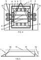
- FIG. 3is a schematic drawing of an end view of the example embodiment of the invention of FIG. 1 showing a relation between the laser slab, two cavity filters, pump lamps, a ceramic reflector, and an external case;
- FIG. 4is a schematic drawing of another example embodiment adding an external water manifold for cooling
- FIG. 5is a schematic drawing of a general cross-section geometry of a laser slab of the example embodiment
- FIG. 6is a schematic drawing of a path of the on-axis laser beam entering and leaving the amplifier slab of an example embodiment
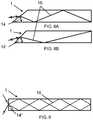
- FIG. 7Ais a schematic drawing of an effect of displacing a laser beam to get separation of an exit beam from the entrance beam for the example embodiment
- FIG. 7Bis a schematic drawing of an effect of displacing a plurality of laser beams for the example embodiment shown in FIG. 7A ;
- FIGS. 8A and 8Bare schematic drawings showing an effect of varying an angle of a wedge at the front of the laser slab in the example embodiment
- FIG. 9is a schematic drawing of an example arrangement for providing an entrance and an exit beam in different directions beam for the example embodiment
- FIGS. 10A and 10Bare schematic drawings showing example separation of the exit beam from the entrance beam by varying the angle of an end reflecting surface in the example embodiment
- FIG. 11is a schematic drawing showing an interior structure of one section of an example amplifier chain using a large slab laser crystal and adding more pump lamps;
- FIG. 12is a schematic drawing showing a cross section of one of the amplifiers in a chain showing how the laser beam enters and exits the gain material
- FIG. 13is a schematic drawing showing an example of combining a plurality of the amplifiers of FIG. 12 in series to provide very high laser output powers.
- a transverse face-pumped, lamp-driven slab laser and amplifier designwith a face to face beam propagation scheme.
- a TIR end bounceredirects the amplified radiation back out the same input facet, but in a different angular direction, making the presented design practical to use in a larger system, if desired.
- the pulse of laser light to be generated or amplifiedpasses through the same piece of gain material at least four times (not the normal two times) in each round trip inside the laser slab. Under the conditions of energy extraction efficiency being ⁇ 60% per pass, this would result in about 97% of the stored energy in the laser slab being extracted. This feature contributes to the higher efficiency of the example device.
- a further example embodimentis the use of pump lamps that use metal or metal halides which produce more photons in a usable spectrum than previous lamp designs based on noble gases.
- Cavity fluorescent filtershave also been employed that convert the non-useful portion of the lamp output (in the ultraviolet portion of the spectrum for the Mercury arc lamps and Indium Iodide plus Thallium Iodide lamps for the Ti Sapphire laser) to useful pump bands at a rather high efficiency.
- the presented lamp pumped designswill have power output levels that exceed the diode pumped versions of these lasers for the same size.
- the efficiency of the visible light output (635-670 nm and 680.4 nm red light) from pump lasers utilized for Alexandrite devicesoperate at approximately 20% efficiency conversion.
- the frequency doubled Nd lasers, which output 532 nm green light, used to pump Titanium Sapphire's green absorption bandalso operate at about 20% electrical to optical conversion efficiency.
- the electrical to optical efficiency of metal arc and metal halide arc lampsare both near 70-73%.
- This improvement and architecturecan be used to amplify pulsed or continuous wave laser beams to very high power levels with a system efficiency that has an upper limit of over forty percent.
- the per head outputis expected to be in the 6.5-15.5 KW range for the head design presented, but the designs are not limited to these power levels.
- FIG. 1shows a schematic of the general configuration of one example embodiment of this invention.
- the ends of the slab crystal 1 and of the six pump lamps 2extend outside of the housing 3 .
- the housingallows for liquid cooling through slots 4 . These slots 4 enter a water manifold external to the housing 3 as will be discussed later.
- FIG. 2shows where cavity filter slabs 5 reside inside the housing on both sides of the laser slab crystal 1 .
- the purpose of the cavity filter slabs 5is to convert the ultra-violet portion of the light emitted from the pump lamps 2 into the visible spectrum where it is more readily absorbed by the slab laser crystal 1 material.
- FIG. 3shows a schematic of an end view of the example embodiment showing the primary elements inside the general casing.
- the center of the structureis the laser slab crystal 1 surrounded on top and bottom by the cavity filter slabs 5 with gaps 8 ′.
- the six lamps 2 used to pump the laser crystal 1are provided outside the cavity filter slabs 5 .
- Surrounding these componentsare four ceramic reflectors 6 which are encased in a housing 7 , which can be made of stainless steel.
- the housing 7 in FIG. 3can be the same type as the housing 3 in FIG. 1 , but that is not a requirement.
- a coolantsuch as cooling water
- FIG. 4shows an example embodiment providing water manifolds 10 used to cool the laser.
- Two manifolds 10cover slots 9 that extend through the external case 7 and through the ceramic reflectors 6 ′. Water is made to flow in opposite directions through the two slots 9 and through the gaps 8 ′ to cool the central laser slab 1 . Water also flows in a separate circuit in the axial direction (in the direction of the pump lamps 2 in FIGS. 2 and 3 ) in gaps 8 to cool the pump lamps 2 .
- the temperatures of the cooling water for the slab laser crystal 1 and for the pump lamps 2can be different, since they are on separate circuits (described below) which allow for the slab to operate at an efficient temperature that is higher than that of the lamps.
- holes 11drilled in the ceramic reflectors 6 ′ which are placed every few inches along the length of the laser slab 1 and the cavity filter slabs 5 . These holes allow for silicon or Teflon bumpers to be used to support the respective slabs and to absorb differences in thermal expansion as the laser elements heat up and thus expand. In addition, the silicon forms a water seal to keep the water between the slab laser crystal 1 and the cavity filter slabs 5 separate from the different temperature water that is cooling the pump lamps 2 .
- the slab laser crystal 1is comprised of Chromium doped Alexandrite (Cr:BeAl 2 O 4 ), but in another example the slab laser crystal can be comprised of Titanium doped Sapphire.
- the bulk of the slab crystalis made up of the doped material. But it could also subsequently be processed with un-doped sections of Alexandrite crystal (BeAl 2 O 4 ) or for the Ti Sapphire, clear undoped Sapphire on the edges and ends via diffusion bonding to produce clear caps.
- the purpose of the clear cap sectionsis to reduce the lens distortion due to thermal gradients produced at high pumping powers. These clear caps reduce the distortion effect by a factor of three as the undoped portion has no heat load from left over or un-extracted energy from the gain material.
- the preferred crystal growth method to produce the laser slab crystalwould be via the classic Heat Exchange Method (HEM).
- HEMHeat Exchange Method
- This crystal growth technologyproduces inclusion-free crystals for either of the example gain materials.
- damage free power limitsof up to 23 gigawatts per square centimeter can be realized for the Alexandrite material (with similar power handling capability results for the Sapphire material as well).
- Alexandrite crystalscan be produced with a power limit of 1-1.5 gigawatts per square centimeter radiance for 1 nanosecond pulse lengths.
- a reflective coatingsuch as of silicon dioxide measuring about a micron thick, can be applied to the sides and possibly the edges to act as a reflector for the amplified laser light and to protect the seals where they may overlap a bounce site.
- the diffusion bonded clear capscan be omitted from the sides and the slab crystal can be enclosed on the sides inside the alumina ceramic cavity reflector with the added design element that a dielectric mirror coating be applied to the two sides and the end of the crystal to facilitate the desired reflections of the amplifying beam. This variation would permit a single seal, compressed around the body of the crystal.
- Example pump lamps 2can utilize Mercury filled (e.g. with a 7 Torr Argon co-fill) clear polished sapphire envelopes or clear fused silica envelopes. Particularly when Sapphire is utilized, Kovar, which is a high nickel alloy that can be used in such lamps as it has a nearly matching expansion coefficient and can be brazed to the envelope using industrially standard techniques. Tungsten electrodes are brazed to the Kovar and are the electrodes establishing the arc in the Mercury.
- Mercury fillede.g. with a 7 Torr Argon co-fill
- Kovarwhich is a high nickel alloy that can be used in such lamps as it has a nearly matching expansion coefficient and can be brazed to the envelope using industrially standard techniques.
- Tungsten electrodesare brazed to the Kovar and are the electrodes establishing the arc in the Mercury.
- the lamps built and energized in such a mannerhave an efficiency of about 72% for Mercury and about 70% for Thallium Iodide. These example lamps are best driven with a high frequency AC power supply. Such power supplies are commercially available and are referred to as ballasts, with operating frequencies of 40-100 kHz.
- the lampis sized by choosing the waste heat removal rate (e.g., 240 W/cm 2 surface area using de-ionized water), and scaling to a useful size.
- a lamp with a bore diameter of 4.5 mm running at 135 V/cmwill pass about 5.8 amps.
- lamps 1 foot longcan be run as high as 35 KW or about 1000 watts per cm. However, for long life, the power is reduced to ⁇ 400 watts per cm and the length is shortened. Normal practice is to use a 6 mm diameter fused clear quartz with a 2 mm bore about 15 cm long. In these lamps energized with an AC power source, there is about a 10% per electrode heat loss and care must be paid to this as unsupportable heat loads can be generated.
- Example cavity filter slabs 5 as shown in FIGS. 1-3are each made up of a rectangular block crystal comprised of Terbium Fluoride (TbF 3 ) doped with ⁇ 0.1% Samarium, which has absorption bands that encompass most of the ultra-violet spectrum.
- TbF 3Terbium Fluoride
- the transfer of energy to the Samarium ionis a nearly lossless non-radiation transfer via the crystal matrix.
- the crystalthen fluoresces at near the absorption band of the Alexandrite crystal, converting otherwise wasted UV energy to useful visible light and thereby increases the pump efficiency of the system.
- the spectral output of Mercury lamps at this power levelis approximately 1 ⁇ 3 in the UV.
- the use of the cavity filter slabs to recycle as much of the UV radiation energy as possibleis desirable for increased efficiency.
- the Terbium Fluoride filter slabsreduce the amount of UV radiation that impinges on the Alexandrite crystal. That radiation, over time, would likely damage the crystal and reduce its transparency which, in turn, limits its usefulness and thus the useful life of the laser device.
- Terbium Garnet with Titanium doped Sapphire gain materialTerbium, Cerium, Titanium doped YALO; Gadolinium, Gallium, Terbium, Cerium, Samarium doped YAG; Terbium Fluoride doped with Samarium; and Terbium-Samarium doped Yttrium Lithium Fluoride.
- Terbium Garnet with Titanium doped Sapphire gain materialTerbium, Cerium, Titanium doped YALO
- Gadolinium, Gallium, Terbium, Cerium, Samarium doped YAGTerbium Fluoride doped with Samarium
- Terbium-Samarium doped Yttrium Lithium FluorideTerbium-Samarium doped Yttrium Lithium Fluoride.
- the example ceramic cavity reflector 6 , 6 ′ as shown in FIG. 4can be comprised of a non-degrading ceramic including a high purity Al 2 O 3 (Alumina) composition. It component can be finished with a sealing glaze that allows for a water tight seal on its edges via compressed silicon rubber seal, preferably white or clear.
- a non-degrading ceramicincluding a high purity Al 2 O 3 (Alumina) composition. It component can be finished with a sealing glaze that allows for a water tight seal on its edges via compressed silicon rubber seal, preferably white or clear.
- the arrangement of the ceramic reflectors 6 , 6 ′resembles a rectangular tube with two rectangular slots at each end to facilitate water flow in the open space 8 along the length of the lamps 2 . This also cools one face of the cavity filter 5 . Additionally, there are square reflector end caps at each end of the pump chamber, in which there are holes allowing the lamps to pass through. There is a separate seal compression plate to allow O-ring seals, of silicon rubber, to be compressed against the lamp walls and the reflector end. At one end there is a rectangular hole for the laser slab to fit through and be sealed via compression O-ring and seal plate.
- FIG. 5shows the side view of the general shape of the example slab laser crystal 1 .
- the shapeis defined by a slab width 12 , a slab length 13 as measured from the midpoint of each end, a wedge angle acting as a Brewster optical window 14 for the face where the incident and exit beams pass through, and an angle 15 for the reflecting end of the crystal. All four of these parameters are interconnected in the example embodiments, and the slab laser crystal 1 should have a specific set of these parameters for desired functioning.
- FIG. 6shows a preferred example situation where the reflecting angle 15 is provided at 90 degrees and the entrance angle is set by the Brewster angle (for example, the Brewster angle for Alexandrite C axis is 60.06 degrees so the wedge angle 14 of the entrance surface is 29.94 degrees), then the desired slab length is uniquely related to the slab width.
- the lengthshould be such that the beam center impinges on the corner of the slab at the reflecting end so that the exit beam is also on the center line.
- the incident and exit beam 16are always co-linear.
- the light 20 from the pump lampsenters the top and bottom faces of the slab while the source laser light enters, and the amplified laser light exits, via the Brewster angle surface.
- the exit beamis also displaced in the opposite direction. This is shown in FIG. 7A , where the single incident beam 16 is halfway between the centerline and the edge of the entrance window. Then, if the incident beam (or plurality of beams) is only half of the size of the window as shown by 17 in FIG. 7B , then the exit beam 17 ′ is physically separate from the incident beam 17 .
- This configurationsolves the problem of the separation of the beams, but limits the beam cross sectional area to be less than half of the size of the slab face.
- the front wedge angle 14is not necessarily required to be set to the complement of the Brewster Angle as in the previous figures. As the angle of the wedge changes, the internal reflection angles of the beam 16 inside the slab changes, and the number of reflections for a given total length changes. Two examples of other incident wedge angles that work for the same length and width are shown in FIGS. 8A and 8B . In the first example of FIG. 8A , the wedge angle 14 is 37.6 degrees, and in the second example of FIG. 8B the wedge angle 14 ′ is 46.2 degrees. It is always possible to find a slab length that will work for a wide range of angles. In all such cases, however, the incident and exit beams are on top of each other (coincident) in the opposite directions.
- preferred example embodimentsprovide for the reflecting surface at the end of the slab to be at an angle different than 90 degrees.
- FIGS. 10A, 10Bfor two example angles 15 and 15 ′.
- the end angle 15is at 88.25 degrees, and this results in the exit beam being separated by 9.41 degrees from the on axis input beam.
- the angle 15 ′is 91.80 degrees, and the exit beam is separated by 13.50 degrees from the input beam.
- Other anglescan be used depending upon the ratio of slab length to slab width, and these two are only shown as examples. This configuration has the desirable features of separating the input and exit beams and allowing for the full aperture to be filled with the incident beam.
- FIG. 11Another example design using the same materials and general arrangement discussed above but with a slightly different architecture is partially shown in FIG. 11 .
- This variationwould permit scaling to much higher power levels.
- the crystal axisis laterally rotated such that the B axis is along the 30 cm dimension.
- a single cavity filter slab 25that lies between the pump lamps 22 and the laser gain material 21 .
- FIG. 12shows a cross section of the example of one of the segments 30 of an example laser amplifier chain, where the segment 30 incorporates the structure in FIG. 11 .
- This figureshows the laser amplifier slab 21 , the cavity filter slab 25 , and the array of pump lamps 22 . Also shown is the ceramic cavity reflector 26 which covers only one side of the amplifier slab 21 , and a stainless steel case 27 .
- the gaps between the amplifier slab 21 and the cavity filter 25allows for the passage of cooling water as before, and the space around the pump lamps 22 also allows for a separate circuit of cooling water.
- the slabsare held in place by seals 29 that keep the water circuits separate and allow for the thermal expansion of the parts as the temperature increases.
- FIG. 12Also shown in FIG. 12 is the path of the amplified laser beam.
- the center of the beamis shown by a solid line 16 as it impinges on the surface of the gain crystal 21 at the Brewster Angle.
- the beamrefracts (changes angle) as it crosses the surface, is totally reflected off the back surface, and exits at the Brewster Angle.
- the beamis wide, as indicated by the dashed lines 16 ′ and 16 ′′ and traverses through the gain medium twice (in and out).
- FIG. 13shows how the amplifier stages 30 could be combined into an amplifier chain to result in an amplified beam of extremely high power.
- the laser beam 16alternately passes through each one of the amplifier stages 30 on each side of the beam path. Between each amplifier stage, there is a reflecting surface 31 which traps the pump lamp photons in a cavity until they are absorbed by the laser gain material.
- the laser amplifiercould be constructed using the example lasers discussed with respect to FIGS. 1-4 . As the power level increases along the amplifier chain, the amplifiers could change in design to the example configuration shown in FIGS. 11-13 .
- the resultis a very high power beam at higher efficiencies than previously possible, up to power handling limit of the exemplified gain materials grown via the HEM method.
- the laser beamis expanded in cross section so this architecture presents a large surface area slab for the beam to interact with.
- the size of the headis limited only by the size of the HEM furnace producing the boule, from which the slab crystal is cut.
- this configurationis made in a 15 cm high by 30 cm long active slab that is 1 cm thick, utilizing a beam cross section of ⁇ 15 cm ⁇ 15 cm, it would generate a beam with an enormous amount of peak and average power in a simple and relatively small device.
- the optimum pump lamp sizeis limited to ⁇ 15 cm in length or 6 Kilowatts of power for 6 mm diameter 2 mm bore envelopes. This limit is due to the 20% heat deposited in the electrodes (corresponding to 10% each end if operated on an AC waveform input).
- the electrode acting as an Anodegets the heat deposition, which occurs on each half cycle. This heat load is manageable in 6 mm diameter quartz tube with a long life. Different dimensions will have different heat removal characteristics and hence different lifetimes.
- the lampwould be constructed with the electrode sections entering at 90 degree arms with the 15 cm arc section between them in an abbreviated “U” configuration.
- This type of lampwould be mounted in staggered parallel sockets through the back reflector such that rows shown in FIG. 11 would be replaced with arrays.
- the arrangementcould be such as to achieve uniform pump light intensity with either Thallium Iodide or Mercury arc lamps used with either Alexandrite (Mercury lamp) or Titanium Sapphire (Thallium Iodide lamp) laser slabs.
- a variation of the above described designsis to use Thallium Iodide along with Mercury as the fill in the arc lamp (this changes the spectrum of the pump light, reference U.S. Pat. No. 7,061,182 that is incorporated by reference, which if modified to include cooling capability and have higher power loading, could be used as the pump light source to provide a longer lifetime at the cost of lower efficiencies).
- Another optionis to use Indium Iodide as the fill inside the sapphire lamps with the Titanium doped sapphire (Ti:Al 2 O 3 ) as the laser slab gain medium. In the case where Indium Iodide lamp is used, a cavity filter would also be desirable for use as the lamp produces UV light.
- a cavity filtercould be avoided for this (Hg/Ar+Thallium Iodide) configuration, since the lamp has an output of 71% at mostly 535 nm. This is a band which is almost at the peak of the Ti:Al 2 O 3 absorption band.
- PLDPulsed Laser Deposition
- a second beam at a higher repetition rate (166 kHz) from a Titanium laser operated as an ultra-fast laseris directed at the in-transit plume of ionic atomic deposition material.
- This double laser usewould greatly improve the quality of the produced films as any ejected particulate matter would be completely converted to atomic ionized matter by the second laser.
- DLCDiamond Like Carbon
- DLC layershave at least four features that make them important for commercial applications.
- DLChas the desirable feature of being extremely hard, and a surface that is coated with DLC will virtually never show any wear.
- DLC layershave very high thermal conductivity (several times higher than copper) which make them ideal for use as thermal spreaders to remove heat from any surface to which it is attached.
- DLC layersare electrically insulating and have very high breakdown voltage ( ⁇ 10,000 volts per micron thickness).
- Fourth DLChas a very low coefficient of thermal expansion, permitting its use as a substrate for fabricating integrated circuits and microelectronic devices with extremely high operating power as the DLC would conduct the heat of operation away from compact monolithic stacked circuit structures.
- theycan be used to provide effective electrical insulation with relatively thin layers or thick wafers/slabs and stacked monolithic architectured blocks for use in many high voltage or otherwise high electric field density applications.
- DLC insulation applied to copper or aluminum wire used in manufacture of various productswould permit a DLC insulated device to operate at higher temperatures than are possible with polymer insulation materials.
- the operating temperature limit for conventional polymer-insulated wire devicesis 200 degrees C.
- the DLC coatingwould function up to its graphitization temperature which begins near 400 degrees C.
- the combination of DLC's thermal conductivity, very low coefficient of thermal expansion, and voltage insulationpermits devices to be built that are several times smaller in physical size than their polymer insulated counterparts and yet would still operate at the same power levels.
- DLC coatings created by Pulsed Laser Deposition (PLD)have been demonstrated on small samples, but the barrier to larger scale commercial applications has been the lack of availability of low cost, higher power lasers like the slab laser disclosed herein.
- PLDPulsed Laser Deposition
- One implementationis to use the Alexandrite laser, such as of a design disclosed herein, to produce high average power Q switch pulses being directed at the donor sputter target, with a Titanium Sapphire version producing 166 KHz or greater pulse speeds being used at the same time and being directed at the plume (thus super pulverizing, atomizing and ionizing it) while it is in flight to the substrate.
- This methodcan be used for any sputter material, and is not limited to graphite.
- Another useful commercial applicationis in the production of low cost solar cells or integrated circuits by PLD.
- Virtually any materialcan be deposited on any substrate in any order and thickness.
- the barrier to commercial applicationshas been the availability of a low cost high power laser source.
- Any of the lasers disclosed hereincan be used to enable the economical high speed generation of high efficiency multi-layer PV (photo-voltaic) films such as Silicon, Germanium, Gallium Arsenide on Germanium, Gallium Nitride, Gallium Indium Nitride, Gallium Phosphide or any other Gallium Alloy, Included is the claim that any existing semiconductor ally currently in existence that has been produced by sputtering, Chemical Vapor or ion deposition on any substrate material can be produced with the described laser system or dual laser systems.
- PV filmscan be grown on suitable thermoplastic surfaces. This would provide a path for flexible PV arrays at low manufacturing cost compared to conventional MOCVD (metal organic chemical vapor deposition) methods.
- MOCVDmetal organic chemical vapor deposition
- High power lasershave a number of applications in the areas of welding and/or cutting.
- the Q switched version of the slab laserwould permit steel plates to be cut that are several to tens of inches thick.
- 20 KW CO 2 lasersare currently being used in shipyards, but 100 kW lasers are rare and very expensive. This would not likely be the case for slab laser systems as disclosed herein, which can be made more economically.
- a high powered laser systemcan also be used for tunneling and/or underground excavation.
- the use of a Q switched pulse train beamwould permit slicing the rock face of a target excavation into thick vertical slabs. If a rectangular section under the slices were to be excavated for the use of an articulated conveyor belt material removal system, and then the cutting beam were to then be directed horizontally several feet above this space on each vertical slice then after the horizontal slices were made then the weight of the slabs of rock, would at some point break the rock free to fall onto an articulated conveyor belt system.
Landscapes
- Physics & Mathematics (AREA)
- Electromagnetism (AREA)
- Engineering & Computer Science (AREA)
- Optics & Photonics (AREA)
- Plasma & Fusion (AREA)
- Chemical & Material Sciences (AREA)
- Crystallography & Structural Chemistry (AREA)
- Manufacturing & Machinery (AREA)
- Power Engineering (AREA)
- General Physics & Mathematics (AREA)
- Computer Hardware Design (AREA)
- Microelectronics & Electronic Packaging (AREA)
- Condensed Matter Physics & Semiconductors (AREA)
- Inorganic Chemistry (AREA)
- Materials Engineering (AREA)
- Chemical Kinetics & Catalysis (AREA)
- Mechanical Engineering (AREA)
- Metallurgy (AREA)
- Organic Chemistry (AREA)
- General Chemical & Material Sciences (AREA)
- Health & Medical Sciences (AREA)
- Toxicology (AREA)
- Lasers (AREA)
- Laser Beam Processing (AREA)
Abstract
Description
Claims (14)
Priority Applications (1)
| Application Number | Priority Date | Filing Date | Title |
|---|---|---|---|
| US14/921,285US10777960B2 (en) | 2011-08-04 | 2015-10-23 | Slab laser and amplifier |
Applications Claiming Priority (3)
| Application Number | Priority Date | Filing Date | Title |
|---|---|---|---|
| US201161515078P | 2011-08-04 | 2011-08-04 | |
| US13/566,144US9246299B2 (en) | 2011-08-04 | 2012-08-03 | Slab laser and amplifier |
| US14/921,285US10777960B2 (en) | 2011-08-04 | 2015-10-23 | Slab laser and amplifier |
Related Parent Applications (1)
| Application Number | Title | Priority Date | Filing Date |
|---|---|---|---|
| US13/566,144ContinuationUS9246299B2 (en) | 2011-08-04 | 2012-08-03 | Slab laser and amplifier |
Publications (2)
| Publication Number | Publication Date |
|---|---|
| US20160043524A1 US20160043524A1 (en) | 2016-02-11 |
| US10777960B2true US10777960B2 (en) | 2020-09-15 |
Family
ID=49548573
Family Applications (5)
| Application Number | Title | Priority Date | Filing Date |
|---|---|---|---|
| US13/566,144Expired - Fee RelatedUS9246299B2 (en) | 2011-08-04 | 2012-08-03 | Slab laser and amplifier |
| US14/418,500Expired - Fee RelatedUS9287112B2 (en) | 2011-08-04 | 2013-08-01 | Slab laser and amplifier and method of use |
| US14/921,285Expired - Fee RelatedUS10777960B2 (en) | 2011-08-04 | 2015-10-23 | Slab laser and amplifier |
| US15/068,950Expired - Fee RelatedUS9525262B2 (en) | 2011-08-04 | 2016-03-14 | Slab laser and amplifier and method of use |
| US15/348,321AbandonedUS20170070022A1 (en) | 2011-08-04 | 2016-11-10 | Slab laser and amplifier and method of use |
Family Applications Before (2)
| Application Number | Title | Priority Date | Filing Date |
|---|---|---|---|
| US13/566,144Expired - Fee RelatedUS9246299B2 (en) | 2011-08-04 | 2012-08-03 | Slab laser and amplifier |
| US14/418,500Expired - Fee RelatedUS9287112B2 (en) | 2011-08-04 | 2013-08-01 | Slab laser and amplifier and method of use |
Family Applications After (2)
| Application Number | Title | Priority Date | Filing Date |
|---|---|---|---|
| US15/068,950Expired - Fee RelatedUS9525262B2 (en) | 2011-08-04 | 2016-03-14 | Slab laser and amplifier and method of use |
| US15/348,321AbandonedUS20170070022A1 (en) | 2011-08-04 | 2016-11-10 | Slab laser and amplifier and method of use |
Country Status (9)
| Country | Link |
|---|---|
| US (5) | US9246299B2 (en) |
| EP (2) | EP2880722B1 (en) |
| JP (2) | JP6415435B2 (en) |
| CN (1) | CN104604049B (en) |
| BR (1) | BR112015002090B1 (en) |
| CA (1) | CA2879746A1 (en) |
| IN (1) | IN2015DN00970A (en) |
| RU (1) | RU2650807C9 (en) |
| WO (1) | WO2014022635A1 (en) |
Families Citing this family (122)
| Publication number | Priority date | Publication date | Assignee | Title |
|---|---|---|---|---|
| WO2014120807A1 (en)* | 2013-01-29 | 2014-08-07 | The Trustees Of Boston College | High thermal conductivity materials for thermal management applications |
| KR102193150B1 (en)* | 2013-12-27 | 2020-12-21 | 삼성디스플레이 주식회사 | Evaporating apparatus, method for controlling evaporation amount using the same |
| KR102192983B1 (en)* | 2014-01-15 | 2020-12-21 | 삼성디스플레이 주식회사 | Evaporating apparatus, method for mesuring evaporation speed using the same |
| CN109080735B (en) | 2014-05-16 | 2022-05-03 | 迪根特技术公司 | Modular forming node for vehicle chassis and using method thereof |
| RU2569904C1 (en)* | 2014-06-25 | 2015-12-10 | Владимир Валентинович Павлов | Laser device having laminar optical element |
| CA2953815A1 (en) | 2014-07-02 | 2016-01-07 | Divergent Technologies, Inc. | Systems and methods for fabricating joint members |
| US10329659B2 (en)* | 2014-08-29 | 2019-06-25 | National Institute Of Advanced Industrial Science And Technology | Method for laser deposition of organic material film or organic-inorganic composite material film, and laser deposition apparatus |
| US10220471B2 (en) | 2015-10-14 | 2019-03-05 | Lawrence Livermore National Security, Llc | Spatter reduction laser scanning strategy in selective laser melting |
| EP4049772A1 (en) | 2015-10-30 | 2022-08-31 | Seurat Technologies, Inc. | Chamber systems for additive manufacturing |
| US11701819B2 (en) | 2016-01-28 | 2023-07-18 | Seurat Technologies, Inc. | Additive manufacturing, spatial heat treating system and method |
| WO2017132668A1 (en)* | 2016-01-29 | 2017-08-03 | Seurat Technologies, Inc. | Additive manufacturing, bond modifying system and method |
| DE102016108474A1 (en) | 2016-05-09 | 2017-11-09 | Deutsches Zentrum für Luft- und Raumfahrt e.V. | Solid state, laser amplification system and solid-state laser |
| WO2017204358A1 (en)* | 2016-05-27 | 2017-11-30 | 富士フイルム株式会社 | Solid-state laser device |
| US10173255B2 (en) | 2016-06-09 | 2019-01-08 | Divergent Technologies, Inc. | Systems and methods for arc and node design and manufacture |
| CN106602391B (en)* | 2016-12-09 | 2019-04-30 | 中国人民解放军海军航空工程学院 | A Slab Laser Module With Wavefront Distortion Self-Correction Capability |
| US10759090B2 (en) | 2017-02-10 | 2020-09-01 | Divergent Technologies, Inc. | Methods for producing panels using 3D-printed tooling shells |
| US11155005B2 (en) | 2017-02-10 | 2021-10-26 | Divergent Technologies, Inc. | 3D-printed tooling and methods for producing same |
| US12251884B2 (en) | 2017-04-28 | 2025-03-18 | Divergent Technologies, Inc. | Support structures in additive manufacturing |
| US10898968B2 (en) | 2017-04-28 | 2021-01-26 | Divergent Technologies, Inc. | Scatter reduction in additive manufacturing |
| CN110869210B (en) | 2017-05-11 | 2022-09-13 | 速尔特技术有限公司 | Switchyard beam routing of patterned light for additive manufacturing |
| US10703419B2 (en) | 2017-05-19 | 2020-07-07 | Divergent Technologies, Inc. | Apparatus and methods for joining panels |
| US11358337B2 (en) | 2017-05-24 | 2022-06-14 | Divergent Technologies, Inc. | Robotic assembly of transport structures using on-site additive manufacturing |
| US11123973B2 (en) | 2017-06-07 | 2021-09-21 | Divergent Technologies, Inc. | Interconnected deflectable panel and node |
| US10919230B2 (en) | 2017-06-09 | 2021-02-16 | Divergent Technologies, Inc. | Node with co-printed interconnect and methods for producing same |
| US10781846B2 (en) | 2017-06-19 | 2020-09-22 | Divergent Technologies, Inc. | 3-D-printed components including fasteners and methods for producing same |
| US10994876B2 (en) | 2017-06-30 | 2021-05-04 | Divergent Technologies, Inc. | Automated wrapping of components in transport structures |
| US11022375B2 (en) | 2017-07-06 | 2021-06-01 | Divergent Technologies, Inc. | Apparatus and methods for additively manufacturing microtube heat exchangers |
| US10895315B2 (en) | 2017-07-07 | 2021-01-19 | Divergent Technologies, Inc. | Systems and methods for implementing node to node connections in mechanized assemblies |
| US10940609B2 (en) | 2017-07-25 | 2021-03-09 | Divergent Technologies, Inc. | Methods and apparatus for additively manufactured endoskeleton-based transport structures |
| US10751800B2 (en) | 2017-07-25 | 2020-08-25 | Divergent Technologies, Inc. | Methods and apparatus for additively manufactured exoskeleton-based transport structures |
| US10605285B2 (en) | 2017-08-08 | 2020-03-31 | Divergent Technologies, Inc. | Systems and methods for joining node and tube structures |
| US10357959B2 (en) | 2017-08-15 | 2019-07-23 | Divergent Technologies, Inc. | Methods and apparatus for additively manufactured identification features |
| US11306751B2 (en) | 2017-08-31 | 2022-04-19 | Divergent Technologies, Inc. | Apparatus and methods for connecting tubes in transport structures |
| US10960611B2 (en) | 2017-09-06 | 2021-03-30 | Divergent Technologies, Inc. | Methods and apparatuses for universal interface between parts in transport structures |
| US11292058B2 (en) | 2017-09-12 | 2022-04-05 | Divergent Technologies, Inc. | Apparatus and methods for optimization of powder removal features in additively manufactured components |
| US10668816B2 (en) | 2017-10-11 | 2020-06-02 | Divergent Technologies, Inc. | Solar extended range electric vehicle with panel deployment and emitter tracking |
| US10814564B2 (en) | 2017-10-11 | 2020-10-27 | Divergent Technologies, Inc. | Composite material inlay in additively manufactured structures |
| US10752986B2 (en)* | 2017-10-30 | 2020-08-25 | Savannah River Nuclear Solutions, Llc | Method of manufacturing a three-dimensional carbon structure |
| US11786971B2 (en) | 2017-11-10 | 2023-10-17 | Divergent Technologies, Inc. | Structures and methods for high volume production of complex structures using interface nodes |
| US10926599B2 (en) | 2017-12-01 | 2021-02-23 | Divergent Technologies, Inc. | Suspension systems using hydraulic dampers |
| US11110514B2 (en) | 2017-12-14 | 2021-09-07 | Divergent Technologies, Inc. | Apparatus and methods for connecting nodes to tubes in transport structures |
| US11085473B2 (en) | 2017-12-22 | 2021-08-10 | Divergent Technologies, Inc. | Methods and apparatus for forming node to panel joints |
| US11534828B2 (en) | 2017-12-27 | 2022-12-27 | Divergent Technologies, Inc. | Assembling structures comprising 3D printed components and standardized components utilizing adhesive circuits |
| US11420262B2 (en) | 2018-01-31 | 2022-08-23 | Divergent Technologies, Inc. | Systems and methods for co-casting of additively manufactured interface nodes |
| US10751934B2 (en) | 2018-02-01 | 2020-08-25 | Divergent Technologies, Inc. | Apparatus and methods for additive manufacturing with variable extruder profiles |
| US11224943B2 (en) | 2018-03-07 | 2022-01-18 | Divergent Technologies, Inc. | Variable beam geometry laser-based powder bed fusion |
| US11267236B2 (en) | 2018-03-16 | 2022-03-08 | Divergent Technologies, Inc. | Single shear joint for node-to-node connections |
| US11254381B2 (en) | 2018-03-19 | 2022-02-22 | Divergent Technologies, Inc. | Manufacturing cell based vehicle manufacturing system and method |
| US11872689B2 (en) | 2018-03-19 | 2024-01-16 | Divergent Technologies, Inc. | End effector features for additively manufactured components |
| US11408216B2 (en) | 2018-03-20 | 2022-08-09 | Divergent Technologies, Inc. | Systems and methods for co-printed or concurrently assembled hinge structures |
| US11613078B2 (en) | 2018-04-20 | 2023-03-28 | Divergent Technologies, Inc. | Apparatus and methods for additively manufacturing adhesive inlet and outlet ports |
| US11214317B2 (en) | 2018-04-24 | 2022-01-04 | Divergent Technologies, Inc. | Systems and methods for joining nodes and other structures |
| US10682821B2 (en) | 2018-05-01 | 2020-06-16 | Divergent Technologies, Inc. | Flexible tooling system and method for manufacturing of composite structures |
| US11020800B2 (en) | 2018-05-01 | 2021-06-01 | Divergent Technologies, Inc. | Apparatus and methods for sealing powder holes in additively manufactured parts |
| US11389816B2 (en) | 2018-05-09 | 2022-07-19 | Divergent Technologies, Inc. | Multi-circuit single port design in additively manufactured node |
| US10691104B2 (en) | 2018-05-16 | 2020-06-23 | Divergent Technologies, Inc. | Additively manufacturing structures for increased spray forming resolution or increased fatigue life |
| US11590727B2 (en) | 2018-05-21 | 2023-02-28 | Divergent Technologies, Inc. | Custom additively manufactured core structures |
| US11441586B2 (en) | 2018-05-25 | 2022-09-13 | Divergent Technologies, Inc. | Apparatus for injecting fluids in node based connections |
| US11035511B2 (en) | 2018-06-05 | 2021-06-15 | Divergent Technologies, Inc. | Quick-change end effector |
| US11292056B2 (en) | 2018-07-06 | 2022-04-05 | Divergent Technologies, Inc. | Cold-spray nozzle |
| CN108963740B (en)* | 2018-07-09 | 2019-08-09 | 北京空间机电研究所 | A slab solid-state laser pumped gain module |
| US11269311B2 (en) | 2018-07-26 | 2022-03-08 | Divergent Technologies, Inc. | Spray forming structural joints |
| US10836120B2 (en) | 2018-08-27 | 2020-11-17 | Divergent Technologies, Inc . | Hybrid composite structures with integrated 3-D printed elements |
| US11433557B2 (en) | 2018-08-28 | 2022-09-06 | Divergent Technologies, Inc. | Buffer block apparatuses and supporting apparatuses |
| US11826953B2 (en) | 2018-09-12 | 2023-11-28 | Divergent Technologies, Inc. | Surrogate supports in additive manufacturing |
| US11072371B2 (en) | 2018-10-05 | 2021-07-27 | Divergent Technologies, Inc. | Apparatus and methods for additively manufactured structures with augmented energy absorption properties |
| US11260582B2 (en) | 2018-10-16 | 2022-03-01 | Divergent Technologies, Inc. | Methods and apparatus for manufacturing optimized panels and other composite structures |
| US12115583B2 (en) | 2018-11-08 | 2024-10-15 | Divergent Technologies, Inc. | Systems and methods for adhesive-based part retention features in additively manufactured structures |
| US12194536B2 (en) | 2018-11-13 | 2025-01-14 | Divergent Technologies, Inc. | 3-D printer with manifolds for gas exchange |
| US11504912B2 (en) | 2018-11-20 | 2022-11-22 | Divergent Technologies, Inc. | Selective end effector modular attachment device |
| USD911222S1 (en) | 2018-11-21 | 2021-02-23 | Divergent Technologies, Inc. | Vehicle and/or replica |
| US12011873B2 (en) | 2018-12-14 | 2024-06-18 | Seurat Technologies, Inc. | Additive manufacturing system for object creation from powder using a high flux laser for two-dimensional printing |
| US11529741B2 (en) | 2018-12-17 | 2022-12-20 | Divergent Technologies, Inc. | System and method for positioning one or more robotic apparatuses |
| US10663110B1 (en) | 2018-12-17 | 2020-05-26 | Divergent Technologies, Inc. | Metrology apparatus to facilitate capture of metrology data |
| US11449021B2 (en) | 2018-12-17 | 2022-09-20 | Divergent Technologies, Inc. | Systems and methods for high accuracy fixtureless assembly |
| SG11202106043WA (en) | 2018-12-19 | 2021-07-29 | Seurat Technologies Inc | Additive manufacturing system using a pulse modulated laser for two-dimensional printing |
| US11885000B2 (en) | 2018-12-21 | 2024-01-30 | Divergent Technologies, Inc. | In situ thermal treatment for PBF systems |
| US20200232070A1 (en) | 2019-01-18 | 2020-07-23 | Divergent Technologies, Inc. | Aluminum alloy compositions |
| JP7341673B2 (en)* | 2019-02-27 | 2023-09-11 | 三菱重工業株式会社 | laser equipment |
| US11203240B2 (en) | 2019-04-19 | 2021-12-21 | Divergent Technologies, Inc. | Wishbone style control arm assemblies and methods for producing same |
| US12314031B1 (en) | 2019-06-27 | 2025-05-27 | Divergent Technologies, Inc. | Incorporating complex geometric features in additively manufactured parts |
| US12280554B2 (en) | 2019-11-21 | 2025-04-22 | Divergent Technologies, Inc. | Fixtureless robotic assembly |
| CN112886378A (en)* | 2019-11-29 | 2021-06-01 | 山东大学 | Passive mode-locked laser for emerald precious stone pumped by 590nm waveband Raman frequency-doubling light source |
| EP4088289A4 (en)* | 2020-01-06 | 2024-03-20 | Battelle Energy Alliance, LLC | Solid state nuclear pumped lasing sensors for in pile reactor power and flux measurement, direct energy conversion, and related methods |
| US11912339B2 (en) | 2020-01-10 | 2024-02-27 | Divergent Technologies, Inc. | 3-D printed chassis structure with self-supporting ribs |
| US11590703B2 (en) | 2020-01-24 | 2023-02-28 | Divergent Technologies, Inc. | Infrared radiation sensing and beam control in electron beam additive manufacturing |
| US11479015B2 (en) | 2020-02-14 | 2022-10-25 | Divergent Technologies, Inc. | Custom formed panels for transport structures and methods for assembling same |
| US11884025B2 (en) | 2020-02-14 | 2024-01-30 | Divergent Technologies, Inc. | Three-dimensional printer and methods for assembling parts via integration of additive and conventional manufacturing operations |
| US12194674B2 (en) | 2020-02-14 | 2025-01-14 | Divergent Technologies, Inc. | Multi-material powder bed fusion 3-D printer |
| US12203397B2 (en) | 2020-02-18 | 2025-01-21 | Divergent Technologies, Inc. | Impact energy absorber with integrated engine exhaust noise muffler |
| CN111293579B (en)* | 2020-02-21 | 2021-07-27 | 中国航空制造技术研究院 | Double-sided water cooling device for lath laser crystal |
| US11421577B2 (en) | 2020-02-25 | 2022-08-23 | Divergent Technologies, Inc. | Exhaust headers with integrated heat shielding and thermal syphoning |
| US11535322B2 (en) | 2020-02-25 | 2022-12-27 | Divergent Technologies, Inc. | Omni-positional adhesion device |
| US12337541B2 (en) | 2020-02-27 | 2025-06-24 | Divergent Technologies, Inc. | Powder bed fusion additive manufacturing system with desiccant positioned within hopper and ultrasonic transducer |
| US11413686B2 (en) | 2020-03-06 | 2022-08-16 | Divergent Technologies, Inc. | Methods and apparatuses for sealing mechanisms for realizing adhesive connections with additively manufactured components |
| US12088055B2 (en)* | 2020-04-10 | 2024-09-10 | Seurat Technologies, Inc. | Fluid edge cladding for spectroscopic absorption of laser emissions and amplified spontaneous emission |
| CN115379943A (en)* | 2020-04-10 | 2022-11-22 | 速尔特技术有限公司 | High throughput additive manufacturing system supporting amplified spontaneous emission in absorption laser amplifiers |
| WO2021252686A1 (en) | 2020-06-10 | 2021-12-16 | Divergent Technologies, Inc. | Adaptive production system |
| US11850804B2 (en) | 2020-07-28 | 2023-12-26 | Divergent Technologies, Inc. | Radiation-enabled retention features for fixtureless assembly of node-based structures |
| US11806941B2 (en) | 2020-08-21 | 2023-11-07 | Divergent Technologies, Inc. | Mechanical part retention features for additively manufactured structures |
| EP4210899A4 (en) | 2020-09-08 | 2024-09-25 | Divergent Technologies, Inc. | CREATING AN ASSEMBLY SEQUENCE |
| EP4217100A4 (en) | 2020-09-22 | 2025-04-30 | Divergent Technologies, Inc. | Methods and apparatuses for ball milling to produce powder for additive manufacturing |
| US12220819B2 (en) | 2020-10-21 | 2025-02-11 | Divergent Technologies, Inc. | 3-D printed metrology feature geometry and detection |
| US12162074B2 (en) | 2020-11-25 | 2024-12-10 | Lawrence Livermore National Security, Llc | System and method for large-area pulsed laser melting of metallic powder in a laser powder bed fusion application |
| US12311612B2 (en) | 2020-12-18 | 2025-05-27 | Divergent Technologies, Inc. | Direct inject joint architecture enabled by quick cure adhesive |
| US12083596B2 (en) | 2020-12-21 | 2024-09-10 | Divergent Technologies, Inc. | Thermal elements for disassembly of node-based adhesively bonded structures |
| US12226824B2 (en) | 2020-12-22 | 2025-02-18 | Divergent Technologies, Inc. | Three dimensional printer with configurable build plate for rapid powder removal |
| US11872626B2 (en) | 2020-12-24 | 2024-01-16 | Divergent Technologies, Inc. | Systems and methods for floating pin joint design |
| US11947335B2 (en) | 2020-12-30 | 2024-04-02 | Divergent Technologies, Inc. | Multi-component structure optimization for combining 3-D printed and commercially available parts |
| US11928966B2 (en) | 2021-01-13 | 2024-03-12 | Divergent Technologies, Inc. | Virtual railroad |
| US12249812B2 (en) | 2021-01-19 | 2025-03-11 | Divergent Technologies, Inc. | Bus bars for printed structural electric battery modules |
| RU2757834C1 (en)* | 2021-01-28 | 2021-10-21 | Акционерное Общество "Наука И Инновации" | Removable cassette for the amplifier module |
| CN116917129A (en) | 2021-03-09 | 2023-10-20 | 戴弗根特技术有限公司 | Rotary additive manufacturing system and method |
| CN117545616A (en) | 2021-04-23 | 2024-02-09 | 戴弗根特技术有限公司 | Removing supports and other materials from surfaces and hollow 3D printed parts |
| US12138772B2 (en) | 2021-04-30 | 2024-11-12 | Divergent Technologies, Inc. | Mobile parts table |
| US12365965B2 (en) | 2021-07-01 | 2025-07-22 | Divergent Technologies, Inc. | Al—Mg—Si based near-eutectic alloy composition for high strength and stiffness applications |
| US11865617B2 (en) | 2021-08-25 | 2024-01-09 | Divergent Technologies, Inc. | Methods and apparatuses for wide-spectrum consumption of output of atomization processes across multi-process and multi-scale additive manufacturing modalities |
| CN113991397B (en)* | 2021-10-28 | 2023-06-27 | 河北工业大学 | Solid laser array amplifier |
| WO2023081059A1 (en) | 2021-11-02 | 2023-05-11 | Divergent Technologies, Inc. | Motor nodes |
| US12152629B2 (en) | 2022-01-25 | 2024-11-26 | Divergent Technologies, Inc. | Attachment structure having a connection member with multiple attachment features |
| CN114779373B (en)* | 2022-03-14 | 2024-03-26 | 清华大学 | Optical power beam splitter and preparation method thereof |
| CN119275690A (en)* | 2024-12-09 | 2025-01-07 | 厦门纽立特电子科技有限公司 | A high power slab laser amplifier |
Citations (55)
| Publication number | Priority date | Publication date | Assignee | Title |
|---|---|---|---|---|
| US3633126A (en) | 1969-04-17 | 1972-01-04 | Gen Electric | Multiple internal reflection face-pumped laser |
| US4734917A (en) | 1985-12-31 | 1988-03-29 | General Electric Company | Fluorescent converter pumped cavity for laser system |
| US4769823A (en) | 1985-12-31 | 1988-09-06 | General Electric Company | Laser system with trivalent chromium doped aluminum tungstate fluorescent converter |
| US4794616A (en) | 1985-12-31 | 1988-12-27 | General Electric Company | Laser system with solid state fluorescent converter matrix having distributed fluorescent converter particles |
| US4838243A (en) | 1987-04-17 | 1989-06-13 | Stephen Kuber | Chimney cleanout tee cap lock |
| US4858243A (en) | 1987-06-12 | 1989-08-15 | Raycon Corporation | Laser pumping cavity |
| JPH0214587A (en) | 1988-06-30 | 1990-01-18 | Mitsubishi Electric Corp | solid state laser device |
| US4989215A (en) | 1988-08-08 | 1991-01-29 | El-Op Electro-Optics Industries Ltd. | Laser pumping cavity |
| US5084889A (en) | 1989-12-20 | 1992-01-28 | Hoya Corporation | Laser medium for use in a slab laser |
| US5239549A (en) | 1990-09-27 | 1993-08-24 | Hoya Corporation | Composite slab laser medium and a laser employing the composite slab laser medium |
| DE4220158A1 (en) | 1992-06-19 | 1993-12-23 | Battelle Institut E V | Selective precipitation of aluminium structures from the gas phase - using locally applied thin aluminium@ layers as catalysts in the pptn. process |
| US5299220A (en) | 1992-09-08 | 1994-03-29 | Brown David C | Slab laser |
| US5305345A (en) | 1992-09-25 | 1994-04-19 | The United States Of America As Represented By The United States Department Of Energy | Zigzag laser with reduced optical distortion |
| US5394427A (en) | 1994-04-29 | 1995-02-28 | Cutting Edge Optronics, Inc. | Housing for a slab laser pumped by a close-coupled light source |
| US5479430A (en) | 1995-02-07 | 1995-12-26 | The Board Of Trustees Of The Leland Stanford Junior University | Protective coating for solid state slab lasers |
| US5553092A (en) | 1994-05-17 | 1996-09-03 | Alliedsignal Inc. | Solid state laser with integral optical diffuser plate to homogenize optical pumping |
| US5581573A (en) | 1993-04-15 | 1996-12-03 | Fuji Electric Co., Ltd. | Solid-state laser device with diffused-light excitation, and integrating sphere |
| US5651021A (en) | 1993-04-21 | 1997-07-22 | The Commonwealth Of Australia | Diode pumped slab laser |
| RU8168U1 (en) | 1997-11-28 | 1998-10-16 | Валерий Геннадиевич Полушкин | ACTIVE LASER ELEMENT WITH WAVE-WATER OPERATION |
| US5832016A (en) | 1997-01-29 | 1998-11-03 | Northrop Grumman Corporation | Slab laser assembly |
| US6014391A (en) | 1997-12-19 | 2000-01-11 | Raytheon Company | Thermally improved slab laser pump cavity apparatus with integral concentrator and method of making same |
| US6118804A (en) | 1995-11-03 | 2000-09-12 | Daimlerchrysler Ag | Laser amplification system |
| US6134258A (en) | 1998-03-25 | 2000-10-17 | The Board Of Trustees Of The Leland Stanford Junior University | Transverse-pumped sLAB laser/amplifier |
| US6219361B1 (en) | 1999-06-21 | 2001-04-17 | Litton Systems, Inc. | Side pumped, Q-switched microlaser |
| US6347101B1 (en) | 1998-04-16 | 2002-02-12 | 3D Systems, Inc. | Laser with absorption optimized pumping of a gain medium |
| US6356575B1 (en) | 1999-07-06 | 2002-03-12 | Raytheon Company | Dual cavity multifunction laser system |
| US6373866B1 (en) | 2000-01-26 | 2002-04-16 | Lumenis Inc. | Solid-state laser with composite prismatic gain-region |
| US20030138021A1 (en) | 2001-10-25 | 2003-07-24 | Norman Hodgson | Diode-pumped solid-state thin slab laser |
| US6738399B1 (en) | 2001-05-17 | 2004-05-18 | The United States Of America As Represented By The United States Department Of Energy | Microchannel cooled edge cladding to establish an adiabatic boundary condition in a slab laser |
| US20050062409A1 (en) | 2003-09-19 | 2005-03-24 | Shunpei Yamazaki | Display device and manufacturing method of display device |
| US20050111496A1 (en) | 2003-11-24 | 2005-05-26 | Reeder Robin A. | Slab laser and method with improved and directionally homogenized beam quality |
| EP1566865A2 (en) | 2004-02-19 | 2005-08-24 | National Institute of Information and Communications Technology Incorporated Administrative Agency | Slab type solid-state laser medium and slab type nonlinear optical medium each using light path formed by multiple reflection caused by three reflecting surfaces |
| EP1646117A2 (en) | 2000-05-30 | 2006-04-12 | Northrop Grumman Corporation | Optical amplifier comprising an end pumped zig-zag slab gain medium |
| US7039087B2 (en) | 2004-05-13 | 2006-05-02 | The United States Of America As Represented By The Department Of The Army | End pumped slab laser cavity |
| US20060114961A1 (en) | 2004-11-26 | 2006-06-01 | Manni Jeffrey G | High-gain diode-pumped laser amplifier |
| US7065121B2 (en) | 2001-07-24 | 2006-06-20 | Gsi Group Ltd. | Waveguide architecture, waveguide devices for laser processing and beam control, and laser processing applications |
| US20060133444A1 (en) | 2004-12-22 | 2006-06-22 | Universal Laser Systems, Inc. | Slab laser with composite resonator and method of producing high-energy laser radiation |
| US7123634B2 (en) | 2004-05-07 | 2006-10-17 | Northrop Grumman Corporation | Zig-zag laser amplifier with polarization controlled reflectors |
| US7280571B2 (en) | 2004-11-23 | 2007-10-09 | Northrop Grumman Corporation | Scalable zig-zag laser amplifier |
| US20080089369A1 (en) | 2006-10-16 | 2008-04-17 | Pavilion Integration Corporation | Injection seeding employing continuous wavelength sweeping for master-slave resonance |
| US7388895B2 (en) | 2003-11-21 | 2008-06-17 | Tsinghua University | Corner-pumping method and gain module for high power slab laser |
| US20080259987A1 (en) | 2004-08-17 | 2008-10-23 | Cambridge Display Technology Limited | Enhanced Emission of Light From Organic Light Emitting Diodes |
| US7505499B2 (en) | 2004-12-15 | 2009-03-17 | Panasonic Corporation | Slab laser amplifier with parasitic oscillation suppression |
| US7515625B2 (en) | 2005-06-21 | 2009-04-07 | National Institute Of Information And Communications Technology, Incorporated Administrative Agency | Multipath laser apparatus using a solid-state slab laser rod |
| US7542489B2 (en) | 2005-03-25 | 2009-06-02 | Pavilion Integration Corporation | Injection seeding employing continuous wavelength sweeping for master-slave resonance |
| US20090201952A1 (en) | 2008-02-12 | 2009-08-13 | Pavilion Integration Corporation | Method and apparatus for producing UV laser from all-solid-state system |
| US7800819B2 (en) | 2005-10-19 | 2010-09-21 | Raytheon Company | Laser amplifier power extraction enhancement system and method |
| US7822091B2 (en) | 2008-07-14 | 2010-10-26 | Lockheed Martin Corporation | Inverted composite slab sandwich laser gain medium |
| US20100296531A1 (en) | 2006-08-02 | 2010-11-25 | Cynosure, Inc. | Picosecond Laser Apparatus and Methods for its Operation and Use |
| US8124995B2 (en) | 2008-06-30 | 2012-02-28 | Kabushiki Kaisha Toshiba | Semiconductor light-emitting device |
| US20120250719A1 (en) | 2011-04-04 | 2012-10-04 | Coherent, Inc. | Transition-metal-doped thin-disk laser |
| US8369375B2 (en) | 2009-03-24 | 2013-02-05 | Kabushiki Kaisha Toshiba | Semiconductor light-emitting device |
| US20130044768A1 (en) | 2011-08-17 | 2013-02-21 | Valeri V. TER-MIKIRTYCHEV | Ultraviolet fiber laser system |
| US8456732B2 (en) | 2009-06-30 | 2013-06-04 | Acpa Energy Conversion Devices Co., Ltd. | Light source wavelength modulator |
| US20130302358A1 (en) | 2010-10-01 | 2013-11-14 | The Trustees Of The University Of Pennsylvania | Morphologically and size uniform monodisperse particles and their shape-directed self-assembly |
Family Cites Families (26)
| Publication number | Priority date | Publication date | Assignee | Title |
|---|---|---|---|---|
| US3631362A (en) | 1968-08-27 | 1971-12-28 | Gen Electric | Face-pumped, face-cooled laser device |
| US3766490A (en)* | 1972-03-14 | 1973-10-16 | Us Army | Lu:nd:yag laser system and material |
| AU1363076A (en)* | 1976-05-04 | 1977-11-10 | Ward H | Laser amplification |
| US5659567A (en)* | 1992-02-19 | 1997-08-19 | Roberts; Rosemary Szewjkowski | Microwave-driven UV light source and solid-state laser |
| JPH05254879A (en)* | 1992-03-06 | 1993-10-05 | Seiko Epson Corp | Fluorescent glass and laser device using the same |
| JPH06125125A (en)* | 1992-05-12 | 1994-05-06 | Mitsubishi Electric Corp | Solid-state laser device |
| JPH06350171A (en)* | 1993-04-15 | 1994-12-22 | Fuji Electric Co Ltd | Solid-state laser device and integrating sphere |
| JPH0927646A (en)* | 1995-07-12 | 1997-01-28 | Hitachi Ltd | Slab laser |
| JPH09199781A (en)* | 1996-01-16 | 1997-07-31 | Nec Corp | Laser amplifier |
| JPH11220191A (en)* | 1998-01-29 | 1999-08-10 | Miyachi Technos Corp | Solid-state laser |
| JP3154689B2 (en)* | 1998-05-26 | 2001-04-09 | 三菱重工業株式会社 | Semiconductor laser pumped slab solid-state laser device. |
| US20050176585A1 (en)* | 2002-04-26 | 2005-08-11 | Sumitomo Electric Industries, Ltd | Process for producing oxide superconductive thin-film |
| US7065109B2 (en)* | 2002-05-08 | 2006-06-20 | Melles Griot Inc. | Laser with narrow bandwidth antireflection filter for frequency selection |
| TWI270918B (en)* | 2003-05-27 | 2007-01-11 | Ip2H Ag | Light source and method for supplying a transport function to a chemical element in a light source |
| US7257302B2 (en)* | 2003-06-03 | 2007-08-14 | Imra America, Inc. | In-line, high energy fiber chirped pulse amplification system |
| JP4754795B2 (en)* | 2003-09-19 | 2011-08-24 | 株式会社半導体エネルギー研究所 | Display device and method for manufacturing display device |
| JP2005294625A (en)* | 2004-04-01 | 2005-10-20 | Sony Corp | Film forming device |
| US7879410B2 (en)* | 2004-06-09 | 2011-02-01 | Imra America, Inc. | Method of fabricating an electrochemical device using ultrafast pulsed laser deposition |
| FI20050216A0 (en)* | 2005-02-23 | 2005-02-23 | Ruuttu Jari | The process produces diamonds, other gemstones such as sapphires, rubies, etc. and performs coatings on these, as well as coatings with other substances such as borides, oxides, nitrides, etc. |
| JP2006307251A (en)* | 2005-04-27 | 2006-11-09 | Kobe Univ | Method for producing diamond-like carbon thin film |
| US7386019B2 (en)* | 2005-05-23 | 2008-06-10 | Time-Bandwidth Products Ag | Light pulse generating apparatus and method |
| US7860142B2 (en)* | 2006-02-07 | 2010-12-28 | Raytheon Company | Laser with spectral converter |
| KR20070117738A (en)* | 2006-06-09 | 2007-12-13 | 삼성전자주식회사 | Repair method of display board and repaired display board |
| US20080116183A1 (en)* | 2006-11-21 | 2008-05-22 | Palo Alto Research Center Incorporated | Light Scanning Mechanism For Scan Displacement Invariant Laser Ablation Apparatus |
| RU2346380C1 (en)* | 2007-07-17 | 2009-02-10 | Общество с ограниченной ответственностью "Мармирус" | Capacitive current generator |
| ATE510042T1 (en)* | 2007-11-21 | 2011-06-15 | Otb Solar Bv | METHOD AND SYSTEM FOR CONTINUOUS OR SEMI-CONTINUOUS LASER-ASSISTED DEPOSITION |
- 2012
- 2012-08-03USUS13/566,144patent/US9246299B2/ennot_activeExpired - Fee Related
- 2013
- 2013-08-01JPJP2015525585Apatent/JP6415435B2/ennot_activeExpired - Fee Related
- 2013-08-01WOPCT/US2013/053166patent/WO2014022635A1/enactiveApplication Filing
- 2013-08-01EPEP13824767.1Apatent/EP2880722B1/enactiveActive
- 2013-08-01EPEP17152815.1Apatent/EP3185373B1/enactiveActive
- 2013-08-01USUS14/418,500patent/US9287112B2/ennot_activeExpired - Fee Related
- 2013-08-01CNCN201380046502.1Apatent/CN104604049B/ennot_activeExpired - Fee Related
- 2013-08-01CACA2879746Apatent/CA2879746A1/ennot_activeAbandoned
- 2013-08-01RURU2015102528Apatent/RU2650807C9/enactive
- 2013-08-01BRBR112015002090-9Apatent/BR112015002090B1/ennot_activeIP Right Cessation
- 2013-08-01ININ970DEN2015patent/IN2015DN00970A/enunknown
- 2015
- 2015-10-23USUS14/921,285patent/US10777960B2/ennot_activeExpired - Fee Related
- 2016
- 2016-03-14USUS15/068,950patent/US9525262B2/ennot_activeExpired - Fee Related
- 2016-11-10USUS15/348,321patent/US20170070022A1/ennot_activeAbandoned
- 2018
- 2018-05-15JPJP2018093437Apatent/JP6743087B2/ennot_activeExpired - Fee Related
Patent Citations (61)
| Publication number | Priority date | Publication date | Assignee | Title |
|---|---|---|---|---|
| US3633126A (en) | 1969-04-17 | 1972-01-04 | Gen Electric | Multiple internal reflection face-pumped laser |
| US4734917A (en) | 1985-12-31 | 1988-03-29 | General Electric Company | Fluorescent converter pumped cavity for laser system |
| US4769823A (en) | 1985-12-31 | 1988-09-06 | General Electric Company | Laser system with trivalent chromium doped aluminum tungstate fluorescent converter |
| US4794616A (en) | 1985-12-31 | 1988-12-27 | General Electric Company | Laser system with solid state fluorescent converter matrix having distributed fluorescent converter particles |
| US4838243A (en) | 1987-04-17 | 1989-06-13 | Stephen Kuber | Chimney cleanout tee cap lock |
| US4858243A (en) | 1987-06-12 | 1989-08-15 | Raycon Corporation | Laser pumping cavity |
| JPH0214587A (en) | 1988-06-30 | 1990-01-18 | Mitsubishi Electric Corp | solid state laser device |
| US4989215A (en) | 1988-08-08 | 1991-01-29 | El-Op Electro-Optics Industries Ltd. | Laser pumping cavity |
| US5084889A (en) | 1989-12-20 | 1992-01-28 | Hoya Corporation | Laser medium for use in a slab laser |
| US5239549A (en) | 1990-09-27 | 1993-08-24 | Hoya Corporation | Composite slab laser medium and a laser employing the composite slab laser medium |
| DE4220158A1 (en) | 1992-06-19 | 1993-12-23 | Battelle Institut E V | Selective precipitation of aluminium structures from the gas phase - using locally applied thin aluminium@ layers as catalysts in the pptn. process |
| US5299220A (en) | 1992-09-08 | 1994-03-29 | Brown David C | Slab laser |
| US5305345A (en) | 1992-09-25 | 1994-04-19 | The United States Of America As Represented By The United States Department Of Energy | Zigzag laser with reduced optical distortion |
| US5581573A (en) | 1993-04-15 | 1996-12-03 | Fuji Electric Co., Ltd. | Solid-state laser device with diffused-light excitation, and integrating sphere |
| US5617442A (en) | 1993-04-15 | 1997-04-01 | Fuji Electric Co., Ltd. | Solid-state laser device with diffused-light excitation, and integrating sphere |
| US5651021A (en) | 1993-04-21 | 1997-07-22 | The Commonwealth Of Australia | Diode pumped slab laser |
| US5394427A (en) | 1994-04-29 | 1995-02-28 | Cutting Edge Optronics, Inc. | Housing for a slab laser pumped by a close-coupled light source |
| US5553092A (en) | 1994-05-17 | 1996-09-03 | Alliedsignal Inc. | Solid state laser with integral optical diffuser plate to homogenize optical pumping |
| US5479430A (en) | 1995-02-07 | 1995-12-26 | The Board Of Trustees Of The Leland Stanford Junior University | Protective coating for solid state slab lasers |
| US6118804A (en) | 1995-11-03 | 2000-09-12 | Daimlerchrysler Ag | Laser amplification system |
| US5832016A (en) | 1997-01-29 | 1998-11-03 | Northrop Grumman Corporation | Slab laser assembly |
| RU8168U1 (en) | 1997-11-28 | 1998-10-16 | Валерий Геннадиевич Полушкин | ACTIVE LASER ELEMENT WITH WAVE-WATER OPERATION |
| US6014391A (en) | 1997-12-19 | 2000-01-11 | Raytheon Company | Thermally improved slab laser pump cavity apparatus with integral concentrator and method of making same |
| US6134258A (en) | 1998-03-25 | 2000-10-17 | The Board Of Trustees Of The Leland Stanford Junior University | Transverse-pumped sLAB laser/amplifier |
| US6347101B1 (en) | 1998-04-16 | 2002-02-12 | 3D Systems, Inc. | Laser with absorption optimized pumping of a gain medium |
| US6219361B1 (en) | 1999-06-21 | 2001-04-17 | Litton Systems, Inc. | Side pumped, Q-switched microlaser |
| US6356575B1 (en) | 1999-07-06 | 2002-03-12 | Raytheon Company | Dual cavity multifunction laser system |
| US6373866B1 (en) | 2000-01-26 | 2002-04-16 | Lumenis Inc. | Solid-state laser with composite prismatic gain-region |
| EP1646117A2 (en) | 2000-05-30 | 2006-04-12 | Northrop Grumman Corporation | Optical amplifier comprising an end pumped zig-zag slab gain medium |
| US6738399B1 (en) | 2001-05-17 | 2004-05-18 | The United States Of America As Represented By The United States Department Of Energy | Microchannel cooled edge cladding to establish an adiabatic boundary condition in a slab laser |
| US7065121B2 (en) | 2001-07-24 | 2006-06-20 | Gsi Group Ltd. | Waveguide architecture, waveguide devices for laser processing and beam control, and laser processing applications |
| US20030138021A1 (en) | 2001-10-25 | 2003-07-24 | Norman Hodgson | Diode-pumped solid-state thin slab laser |
| US20050062409A1 (en) | 2003-09-19 | 2005-03-24 | Shunpei Yamazaki | Display device and manufacturing method of display device |
| US7388895B2 (en) | 2003-11-21 | 2008-06-17 | Tsinghua University | Corner-pumping method and gain module for high power slab laser |
| US20050111496A1 (en) | 2003-11-24 | 2005-05-26 | Reeder Robin A. | Slab laser and method with improved and directionally homogenized beam quality |
| US7376160B2 (en) | 2003-11-24 | 2008-05-20 | Raytheon Company | Slab laser and method with improved and directionally homogenized beam quality |
| EP1566865A2 (en) | 2004-02-19 | 2005-08-24 | National Institute of Information and Communications Technology Incorporated Administrative Agency | Slab type solid-state laser medium and slab type nonlinear optical medium each using light path formed by multiple reflection caused by three reflecting surfaces |
| US7123634B2 (en) | 2004-05-07 | 2006-10-17 | Northrop Grumman Corporation | Zig-zag laser amplifier with polarization controlled reflectors |
| US7039087B2 (en) | 2004-05-13 | 2006-05-02 | The United States Of America As Represented By The Department Of The Army | End pumped slab laser cavity |
| US20110069732A1 (en) | 2004-08-17 | 2011-03-24 | Cambridge Display Technology Limited | Enhanced emission of light from organic light emitting diodes |
| US20080259987A1 (en) | 2004-08-17 | 2008-10-23 | Cambridge Display Technology Limited | Enhanced Emission of Light From Organic Light Emitting Diodes |
| US7280571B2 (en) | 2004-11-23 | 2007-10-09 | Northrop Grumman Corporation | Scalable zig-zag laser amplifier |
| US7590160B2 (en) | 2004-11-26 | 2009-09-15 | Manni Jeffrey G | High-gain diode-pumped laser amplifier |
| US20060114961A1 (en) | 2004-11-26 | 2006-06-01 | Manni Jeffrey G | High-gain diode-pumped laser amplifier |
| US7505499B2 (en) | 2004-12-15 | 2009-03-17 | Panasonic Corporation | Slab laser amplifier with parasitic oscillation suppression |
| US20060133444A1 (en) | 2004-12-22 | 2006-06-22 | Universal Laser Systems, Inc. | Slab laser with composite resonator and method of producing high-energy laser radiation |
| US7542489B2 (en) | 2005-03-25 | 2009-06-02 | Pavilion Integration Corporation | Injection seeding employing continuous wavelength sweeping for master-slave resonance |
| US7515625B2 (en) | 2005-06-21 | 2009-04-07 | National Institute Of Information And Communications Technology, Incorporated Administrative Agency | Multipath laser apparatus using a solid-state slab laser rod |
| US7800819B2 (en) | 2005-10-19 | 2010-09-21 | Raytheon Company | Laser amplifier power extraction enhancement system and method |
| US7929579B2 (en) | 2006-08-02 | 2011-04-19 | Cynosure, Inc. | Picosecond laser apparatus and methods for its operation and use |
| US20100296531A1 (en) | 2006-08-02 | 2010-11-25 | Cynosure, Inc. | Picosecond Laser Apparatus and Methods for its Operation and Use |
| US20080089369A1 (en) | 2006-10-16 | 2008-04-17 | Pavilion Integration Corporation | Injection seeding employing continuous wavelength sweeping for master-slave resonance |
| US7633979B2 (en) | 2008-02-12 | 2009-12-15 | Pavilion Integration Corporation | Method and apparatus for producing UV laser from all-solid-state system |
| US20090201952A1 (en) | 2008-02-12 | 2009-08-13 | Pavilion Integration Corporation | Method and apparatus for producing UV laser from all-solid-state system |
| US8124995B2 (en) | 2008-06-30 | 2012-02-28 | Kabushiki Kaisha Toshiba | Semiconductor light-emitting device |
| US7822091B2 (en) | 2008-07-14 | 2010-10-26 | Lockheed Martin Corporation | Inverted composite slab sandwich laser gain medium |
| US8369375B2 (en) | 2009-03-24 | 2013-02-05 | Kabushiki Kaisha Toshiba | Semiconductor light-emitting device |
| US8456732B2 (en) | 2009-06-30 | 2013-06-04 | Acpa Energy Conversion Devices Co., Ltd. | Light source wavelength modulator |
| US20130302358A1 (en) | 2010-10-01 | 2013-11-14 | The Trustees Of The University Of Pennsylvania | Morphologically and size uniform monodisperse particles and their shape-directed self-assembly |
| US20120250719A1 (en) | 2011-04-04 | 2012-10-04 | Coherent, Inc. | Transition-metal-doped thin-disk laser |
| US20130044768A1 (en) | 2011-08-17 | 2013-02-21 | Valeri V. TER-MIKIRTYCHEV | Ultraviolet fiber laser system |
Non-Patent Citations (3)
| Title |
|---|
| Article "Active Mirror: A large-aperture medium-repetition rate Nd:glass amplifier" published Jan. 15, 1981; 2219 Applied Optics; pp. 251-361; vol. 20, No. 2 Jan. 15, 1981 New York USA. |
| Extended European Search Report; Application No. EP 13 82 4767; Place of Search: Munich; Date of Completion of Search: Mar. 18, 2016. |
| International Search Report; International Application No. PCT/US2013/053166; International Filing Date: Aug. 1, 2013; Date of Actual Completion of International Search: Oct. 24, 2013; Date of Mailing of International Search Report: dated Nov. 28, 2013. |
Also Published As
| Publication number | Publication date |
|---|---|
| BR112015002090B1 (en) | 2021-05-25 |
| WO2014022635A1 (en) | 2014-02-06 |
| EP2880722B1 (en) | 2019-10-09 |
| BR112015002090A2 (en) | 2017-07-04 |
| EP2880722A4 (en) | 2016-04-27 |
| JP6743087B2 (en) | 2020-08-19 |
| CN104604049B (en) | 2019-08-13 |
| RU2650807C2 (en) | 2018-04-17 |
| CA2879746A1 (en) | 2014-02-06 |
| JP2018164090A (en) | 2018-10-18 |
| RU2650807C9 (en) | 2018-09-06 |
| EP3185373B1 (en) | 2021-04-07 |
| CN104604049A (en) | 2015-05-06 |
| US9287112B2 (en) | 2016-03-15 |
| US20160043524A1 (en) | 2016-02-11 |
| US20130301662A1 (en) | 2013-11-14 |
| US9525262B2 (en) | 2016-12-20 |
| IN2015DN00970A (en) | 2015-06-12 |
| US20150311064A1 (en) | 2015-10-29 |
| JP6415435B2 (en) | 2018-10-31 |
| EP3185373A1 (en) | 2017-06-28 |
| RU2015102528A (en) | 2016-09-20 |
| JP2015528217A (en) | 2015-09-24 |
| US9246299B2 (en) | 2016-01-26 |
| US20170070022A1 (en) | 2017-03-09 |
| US20160211637A1 (en) | 2016-07-21 |
| EP2880722A1 (en) | 2015-06-10 |
Similar Documents
| Publication | Publication Date | Title |
|---|---|---|
| US10777960B2 (en) | Slab laser and amplifier | |
| US20090274189A1 (en) | Scalable thermally efficient pump diode systems | |
| WO2010145855A1 (en) | Monolithic, side pumped solid-state laser and method for operating the same | |
| Yagi et al. | Highly efficient flashlamp-pumped Cr3+ and Nd3+ codoped Y3Al5O12 ceramic laser | |
| US20110069731A1 (en) | Scalable thermally efficient pump diode assemblies | |
| Hein et al. | POLARIS: an all diode-pumped ultrahigh peak power laser for high repetition rates | |
| RU2746445C2 (en) | High power amplifier on a crystal doped with rare earth elements, based on a superlow quantum defected injection circuit using single-mode or low-mode fiber lasers | |
| Hoffstadt | Design and performance of a high-average-power flashlamp-pumped Ti: sapphire laser and amplifier | |
| EP2102949B1 (en) | Scalable thermally efficient pump diode systems | |
| RU2461932C2 (en) | Semiconductor disc laser | |
| Caffey et al. | Diode array side‐pumped neodymium‐doped gadolinium scandium gallium garnet rod and slab lasers | |
| US20070036194A1 (en) | Excimer-lamp pumped semiconductor laser | |
| Nikolaev et al. | Generation of microsecond laser pulses in polyurethane matrices doped with dyes | |
| JP2001223423A (en) | Laser equipment | |
| A1 | POLARIS-OVERVIEW | |
| Liu et al. | Directly diode-pumped Yb: glass laser with 2.8-W cw output power | |
| Yagi et al. | Flashlamp-pumped Nd: YAG ceramic laser | |
| Kim | Optical Pumping of High Power Lasers with an Array of Plasma Pinches. | |
| Sauerbrey | J. Hein, MC Kaluza, R. Bödefeld, M. Siebold, S. Podleska, and | |
| JP2000150991A (en) | Parallel light generator |
Legal Events
| Date | Code | Title | Description |
|---|---|---|---|
| STPP | Information on status: patent application and granting procedure in general | Free format text:AMENDMENT AFTER NOTICE OF APPEAL | |
| STPP | Information on status: patent application and granting procedure in general | Free format text:NON FINAL ACTION MAILED | |
| STPP | Information on status: patent application and granting procedure in general | Free format text:RESPONSE TO NON-FINAL OFFICE ACTION ENTERED AND FORWARDED TO EXAMINER | |
| STPP | Information on status: patent application and granting procedure in general | Free format text:FINAL REJECTION MAILED | |
| STPP | Information on status: patent application and granting procedure in general | Free format text:RESPONSE AFTER FINAL ACTION FORWARDED TO EXAMINER | |
| STPP | Information on status: patent application and granting procedure in general | Free format text:RESPONSE AFTER FINAL ACTION FORWARDED TO EXAMINER | |
| STPP | Information on status: patent application and granting procedure in general | Free format text:NOTICE OF ALLOWANCE MAILED -- APPLICATION RECEIVED IN OFFICE OF PUBLICATIONS | |
| ZAAA | Notice of allowance and fees due | Free format text:ORIGINAL CODE: NOA | |
| ZAAB | Notice of allowance mailed | Free format text:ORIGINAL CODE: MN/=. | |
| STCB | Information on status: application discontinuation | Free format text:ABANDONED -- FAILURE TO PAY ISSUE FEE | |
| STPP | Information on status: patent application and granting procedure in general | Free format text:PUBLICATIONS -- ISSUE FEE PAYMENT VERIFIED | |
| STCF | Information on status: patent grant | Free format text:PATENTED CASE | |
| FEPP | Fee payment procedure | Free format text:MAINTENANCE FEE REMINDER MAILED (ORIGINAL EVENT CODE: REM.); ENTITY STATUS OF PATENT OWNER: SMALL ENTITY | |
| LAPS | Lapse for failure to pay maintenance fees | Free format text:PATENT EXPIRED FOR FAILURE TO PAY MAINTENANCE FEES (ORIGINAL EVENT CODE: EXP.); ENTITY STATUS OF PATENT OWNER: SMALL ENTITY | |
| STCH | Information on status: patent discontinuation | Free format text:PATENT EXPIRED DUE TO NONPAYMENT OF MAINTENANCE FEES UNDER 37 CFR 1.362 | |
| FP | Lapsed due to failure to pay maintenance fee | Effective date:20240915 |