US10775458B2 - Method and system for non-invasive measurement of metabolic health - Google Patents
Method and system for non-invasive measurement of metabolic healthDownload PDFInfo
- Publication number
- US10775458B2 US10775458B2US15/911,728US201815911728AUS10775458B2US 10775458 B2US10775458 B2US 10775458B2US 201815911728 AUS201815911728 AUS 201815911728AUS 10775458 B2US10775458 B2US 10775458B2
- Authority
- US
- United States
- Prior art keywords
- magnet
- probe
- magnetic field
- nmr
- magnets
- Prior art date
- Legal status (The legal status is an assumption and is not a legal conclusion. Google has not performed a legal analysis and makes no representation as to the accuracy of the status listed.)
- Active, expires
Links
- 238000000034methodMethods0.000titleclaimsdescription52
- 230000010034metabolic healthEffects0.000titleclaimsdescription34
- 238000005259measurementMethods0.000titleclaimsdescription14
- 239000000523sampleSubstances0.000claimsabstractdescription68
- 238000010339medical testMethods0.000claimsabstractdescription19
- 230000008859changeEffects0.000claimsabstractdescription9
- 238000012360testing methodMethods0.000claimsdescription31
- 210000000577adipose tissueAnatomy0.000claimsdescription26
- 210000001519tissueAnatomy0.000claimsdescription17
- 229940058401polytetrafluoroethyleneDrugs0.000claimsdescription13
- 229920001343polytetrafluoroethylenePolymers0.000claimsdescription13
- 239000004810polytetrafluoroethyleneSubstances0.000claimsdescription13
- 229910052761rare earth metalInorganic materials0.000claimsdescription7
- 150000002910rare earth metalsChemical class0.000claimsdescription7
- 235000009508confectioneryNutrition0.000claimsdescription4
- 239000012212insulatorSubstances0.000claimsdescription3
- -1poly tetrafluoroethylenePolymers0.000claimsdescription2
- 238000005481NMR spectroscopyMethods0.000description87
- 238000012545processingMethods0.000description17
- 238000000679relaxometryMethods0.000description16
- 239000008280bloodSubstances0.000description14
- 210000004369bloodAnatomy0.000description14
- 208000001072type 2 diabetes mellitusDiseases0.000description14
- 238000004891communicationMethods0.000description9
- 206010022489Insulin ResistanceDiseases0.000description8
- 206010012601diabetes mellitusDiseases0.000description8
- NOESYZHRGYRDHS-UHFFFAOYSA-NinsulinChemical compoundN1C(=O)C(NC(=O)C(CCC(N)=O)NC(=O)C(CCC(O)=O)NC(=O)C(C(C)C)NC(=O)C(NC(=O)CN)C(C)CC)CSSCC(C(NC(CO)C(=O)NC(CC(C)C)C(=O)NC(CC=2C=CC(O)=CC=2)C(=O)NC(CCC(N)=O)C(=O)NC(CC(C)C)C(=O)NC(CCC(O)=O)C(=O)NC(CC(N)=O)C(=O)NC(CC=2C=CC(O)=CC=2)C(=O)NC(CSSCC(NC(=O)C(C(C)C)NC(=O)C(CC(C)C)NC(=O)C(CC=2C=CC(O)=CC=2)NC(=O)C(CC(C)C)NC(=O)C(C)NC(=O)C(CCC(O)=O)NC(=O)C(C(C)C)NC(=O)C(CC(C)C)NC(=O)C(CC=2NC=NC=2)NC(=O)C(CO)NC(=O)CNC2=O)C(=O)NCC(=O)NC(CCC(O)=O)C(=O)NC(CCCNC(N)=N)C(=O)NCC(=O)NC(CC=3C=CC=CC=3)C(=O)NC(CC=3C=CC=CC=3)C(=O)NC(CC=3C=CC(O)=CC=3)C(=O)NC(C(C)O)C(=O)N3C(CCC3)C(=O)NC(CCCCN)C(=O)NC(C)C(O)=O)C(=O)NC(CC(N)=O)C(O)=O)=O)NC(=O)C(C(C)CC)NC(=O)C(CO)NC(=O)C(C(C)O)NC(=O)C1CSSCC2NC(=O)C(CC(C)C)NC(=O)C(NC(=O)C(CCC(N)=O)NC(=O)C(CC(N)=O)NC(=O)C(NC(=O)C(N)CC=1C=CC=CC=1)C(C)C)CC1=CN=CN1NOESYZHRGYRDHS-UHFFFAOYSA-N0.000description8
- WQZGKKKJIJFFOK-GASJEMHNSA-NGlucoseNatural productsOC[C@H]1OC(O)[C@H](O)[C@@H](O)[C@@H]1OWQZGKKKJIJFFOK-GASJEMHNSA-N0.000description6
- 208000001145Metabolic SyndromeDiseases0.000description6
- 201000000690abdominal obesity-metabolic syndromeDiseases0.000description6
- 239000008103glucoseSubstances0.000description6
- 239000000463materialSubstances0.000description6
- 239000000203mixtureSubstances0.000description6
- 206010061218InflammationDiseases0.000description5
- 238000009534blood testMethods0.000description5
- 238000010586diagramMethods0.000description5
- 230000006870functionEffects0.000description5
- 238000003384imaging methodMethods0.000description5
- 230000004054inflammatory processEffects0.000description5
- 150000002632lipidsChemical class0.000description5
- 102000004877InsulinHuman genes0.000description4
- 108090001061InsulinProteins0.000description4
- 238000004458analytical methodMethods0.000description4
- 229940125396insulinDrugs0.000description4
- 210000000496pancreasAnatomy0.000description4
- 239000004033plasticSubstances0.000description4
- 238000012216screeningMethods0.000description4
- 230000003248secreting effectEffects0.000description4
- 208000024172Cardiovascular diseaseDiseases0.000description3
- 208000012266Needlestick injuryDiseases0.000description3
- 235000005911dietNutrition0.000description3
- 230000037213dietEffects0.000description3
- 201000010099diseaseDiseases0.000description3
- 208000037265diseases, disorders, signs and symptomsDiseases0.000description3
- 239000012530fluidSubstances0.000description3
- 230000036541healthEffects0.000description3
- 125000004435hydrogen atomChemical group[H]*0.000description3
- 230000006371metabolic abnormalityEffects0.000description3
- 230000004060metabolic processEffects0.000description3
- 238000012986modificationMethods0.000description3
- 230000004048modificationEffects0.000description3
- 238000012544monitoring processMethods0.000description3
- 238000001208nuclear magnetic resonance pulse sequenceMethods0.000description3
- 238000004611spectroscopical analysisMethods0.000description3
- XLYOFNOQVPJJNP-UHFFFAOYSA-NwaterSubstancesOXLYOFNOQVPJJNP-UHFFFAOYSA-N0.000description3
- 241000251468ActinopterygiiSpecies0.000description2
- 206010003210ArteriosclerosisDiseases0.000description2
- 201000001320AtherosclerosisDiseases0.000description2
- 206010016654FibrosisDiseases0.000description2
- 206010018429Glucose tolerance impairedDiseases0.000description2
- 102000004895LipoproteinsHuman genes0.000description2
- 108090001030LipoproteinsProteins0.000description2
- 208000001280Prediabetic StateDiseases0.000description2
- 238000013461designMethods0.000description2
- 238000001514detection methodMethods0.000description2
- 238000003745diagnosisMethods0.000description2
- 230000004761fibrosisEffects0.000description2
- 235000021323fish oilNutrition0.000description2
- 239000000696magnetic materialSubstances0.000description2
- 238000002595magnetic resonance imagingMethods0.000description2
- 229910001172neodymium magnetInorganic materials0.000description2
- 201000009104prediabetes syndromeDiseases0.000description2
- 235000021003saturated fatsNutrition0.000description2
- 210000002435tendonAnatomy0.000description2
- 229910001369BrassInorganic materials0.000description1
- 108010074051C-Reactive ProteinProteins0.000description1
- 102100032752C-reactive proteinHuman genes0.000description1
- 102000010834Extracellular Matrix ProteinsHuman genes0.000description1
- 108010037362Extracellular Matrix ProteinsProteins0.000description1
- 102000001554HemoglobinsHuman genes0.000description1
- 108010054147HemoglobinsProteins0.000description1
- UFHFLCQGNIYNRP-UHFFFAOYSA-NHydrogenChemical compound[H][H]UFHFLCQGNIYNRP-UHFFFAOYSA-N0.000description1
- 208000031773Insulin resistance syndromeDiseases0.000description1
- 238000012565NMR experimentMethods0.000description1
- 229910052779NeodymiumInorganic materials0.000description1
- 208000008589ObesityDiseases0.000description1
- 229910000831SteelInorganic materials0.000description1
- QJVKUMXDEUEQLH-UHFFFAOYSA-N[B].[Fe].[Nd]Chemical compound[B].[Fe].[Nd]QJVKUMXDEUEQLH-UHFFFAOYSA-N0.000description1
- 230000005856abnormalityEffects0.000description1
- 230000009471actionEffects0.000description1
- 210000001789adipocyteAnatomy0.000description1
- XAGFODPZIPBFFR-UHFFFAOYSA-NaluminiumChemical compound[Al]XAGFODPZIPBFFR-UHFFFAOYSA-N0.000description1
- 229910052782aluminiumInorganic materials0.000description1
- 230000004888barrier functionEffects0.000description1
- 210000000227basophil cell of anterior lobe of hypophysisAnatomy0.000description1
- 230000005540biological transmissionEffects0.000description1
- 239000000090biomarkerSubstances0.000description1
- 210000004204blood vesselAnatomy0.000description1
- 239000010951brassSubstances0.000description1
- 239000003990capacitorSubstances0.000description1
- 230000010035cardiometabolic healthEffects0.000description1
- 210000004027cellAnatomy0.000description1
- 239000003153chemical reaction reagentSubstances0.000description1
- 230000001447compensatory effectEffects0.000description1
- 238000004883computer applicationMethods0.000description1
- 238000004590computer programMethods0.000description1
- 238000013480data collectionMethods0.000description1
- 230000001934delayEffects0.000description1
- 238000002405diagnostic procedureMethods0.000description1
- 235000014113dietary fatty acidsNutrition0.000description1
- 239000006185dispersionSubstances0.000description1
- 230000002526effect on cardiovascular systemEffects0.000description1
- 238000005516engineering processMethods0.000description1
- 210000002744extracellular matrixAnatomy0.000description1
- 229930195729fatty acidNatural products0.000description1
- 239000000194fatty acidSubstances0.000description1
- 150000004665fatty acidsChemical class0.000description1
- 239000000835fiberSubstances0.000description1
- 239000011521glassSubstances0.000description1
- 230000003862health statusEffects0.000description1
- 239000001257hydrogenSubstances0.000description1
- 229910052739hydrogenInorganic materials0.000description1
- 210000002865immune cellAnatomy0.000description1
- 230000006872improvementEffects0.000description1
- 239000007788liquidSubstances0.000description1
- 210000002751lymphAnatomy0.000description1
- 239000003550markerSubstances0.000description1
- 238000000968medical method and processMethods0.000description1
- 230000005055memory storageEffects0.000description1
- 230000002503metabolic effectEffects0.000description1
- QEFYFXOXNSNQGX-UHFFFAOYSA-Nneodymium atomChemical compound[Nd]QEFYFXOXNSNQGX-UHFFFAOYSA-N0.000description1
- 239000012299nitrogen atmosphereSubstances0.000description1
- 235000020824obesityNutrition0.000description1
- 235000020660omega-3 fatty acidNutrition0.000description1
- 230000003287optical effectEffects0.000description1
- 239000002245particleSubstances0.000description1
- 230000002093peripheral effectEffects0.000description1
- 238000007639printingMethods0.000description1
- 230000008569processEffects0.000description1
- 230000008742procoagulationEffects0.000description1
- 230000000770proinflammatory effectEffects0.000description1
- 102000004169proteins and genesHuman genes0.000description1
- 108090000623proteins and genesProteins0.000description1
- 230000004044responseEffects0.000description1
- 210000002966serumAnatomy0.000description1
- 229910001220stainless steelInorganic materials0.000description1
- 239000010935stainless steelSubstances0.000description1
- 239000010959steelSubstances0.000description1
- 239000000126substanceSubstances0.000description1
- 238000011282treatmentMethods0.000description1
- 239000011800void materialSubstances0.000description1
Images


Classifications
- G—PHYSICS
- G01—MEASURING; TESTING
- G01R—MEASURING ELECTRIC VARIABLES; MEASURING MAGNETIC VARIABLES
- G01R33/00—Arrangements or instruments for measuring magnetic variables
- G01R33/20—Arrangements or instruments for measuring magnetic variables involving magnetic resonance
- G01R33/28—Details of apparatus provided for in groups G01R33/44 - G01R33/64
- G01R33/30—Sample handling arrangements, e.g. sample cells, spinning mechanisms
- G01R33/302—Miniaturized sample handling arrangements for sampling small quantities, e.g. flow-through microfluidic NMR chips
- A—HUMAN NECESSITIES
- A61—MEDICAL OR VETERINARY SCIENCE; HYGIENE
- A61B—DIAGNOSIS; SURGERY; IDENTIFICATION
- A61B5/00—Measuring for diagnostic purposes; Identification of persons
- A61B5/05—Detecting, measuring or recording for diagnosis by means of electric currents or magnetic fields; Measuring using microwaves or radio waves
- A61B5/055—Detecting, measuring or recording for diagnosis by means of electric currents or magnetic fields; Measuring using microwaves or radio waves involving electronic [EMR] or nuclear [NMR] magnetic resonance, e.g. magnetic resonance imaging
- A—HUMAN NECESSITIES
- A61—MEDICAL OR VETERINARY SCIENCE; HYGIENE
- A61B—DIAGNOSIS; SURGERY; IDENTIFICATION
- A61B5/00—Measuring for diagnostic purposes; Identification of persons
- A61B5/48—Other medical applications
- A61B5/4866—Evaluating metabolism
- A—HUMAN NECESSITIES
- A61—MEDICAL OR VETERINARY SCIENCE; HYGIENE
- A61B—DIAGNOSIS; SURGERY; IDENTIFICATION
- A61B5/00—Measuring for diagnostic purposes; Identification of persons
- A61B5/48—Other medical applications
- A61B5/4869—Determining body composition
- A61B5/4872—Body fat
- A—HUMAN NECESSITIES
- A61—MEDICAL OR VETERINARY SCIENCE; HYGIENE
- A61B—DIAGNOSIS; SURGERY; IDENTIFICATION
- A61B5/00—Measuring for diagnostic purposes; Identification of persons
- A61B5/68—Arrangements of detecting, measuring or recording means, e.g. sensors, in relation to patient
- A61B5/6801—Arrangements of detecting, measuring or recording means, e.g. sensors, in relation to patient specially adapted to be attached to or worn on the body surface
- A61B5/6813—Specially adapted to be attached to a specific body part
- A61B5/6825—Hand
- A61B5/6826—Finger
- G—PHYSICS
- G01—MEASURING; TESTING
- G01R—MEASURING ELECTRIC VARIABLES; MEASURING MAGNETIC VARIABLES
- G01R33/00—Arrangements or instruments for measuring magnetic variables
- G01R33/20—Arrangements or instruments for measuring magnetic variables involving magnetic resonance
- G—PHYSICS
- G01—MEASURING; TESTING
- G01R—MEASURING ELECTRIC VARIABLES; MEASURING MAGNETIC VARIABLES
- G01R33/00—Arrangements or instruments for measuring magnetic variables
- G01R33/20—Arrangements or instruments for measuring magnetic variables involving magnetic resonance
- G01R33/28—Details of apparatus provided for in groups G01R33/44 - G01R33/64
- G01R33/30—Sample handling arrangements, e.g. sample cells, spinning mechanisms
- G—PHYSICS
- G01—MEASURING; TESTING
- G01R—MEASURING ELECTRIC VARIABLES; MEASURING MAGNETIC VARIABLES
- G01R33/00—Arrangements or instruments for measuring magnetic variables
- G01R33/20—Arrangements or instruments for measuring magnetic variables involving magnetic resonance
- G01R33/28—Details of apparatus provided for in groups G01R33/44 - G01R33/64
- G01R33/38—Systems for generation, homogenisation or stabilisation of the main or gradient magnetic field
- G01R33/383—Systems for generation, homogenisation or stabilisation of the main or gradient magnetic field using permanent magnets
- G—PHYSICS
- G01—MEASURING; TESTING
- G01R—MEASURING ELECTRIC VARIABLES; MEASURING MAGNETIC VARIABLES
- G01R33/00—Arrangements or instruments for measuring magnetic variables
- G01R33/20—Arrangements or instruments for measuring magnetic variables involving magnetic resonance
- G01R33/44—Arrangements or instruments for measuring magnetic variables involving magnetic resonance using nuclear magnetic resonance [NMR]
- G01R33/448—Relaxometry, i.e. quantification of relaxation times or spin density
- G—PHYSICS
- G01—MEASURING; TESTING
- G01R—MEASURING ELECTRIC VARIABLES; MEASURING MAGNETIC VARIABLES
- G01R33/00—Arrangements or instruments for measuring magnetic variables
- G01R33/20—Arrangements or instruments for measuring magnetic variables involving magnetic resonance
- G01R33/28—Details of apparatus provided for in groups G01R33/44 - G01R33/64
- G01R33/30—Sample handling arrangements, e.g. sample cells, spinning mechanisms
- G01R33/31—Temperature control thereof
- G—PHYSICS
- G01—MEASURING; TESTING
- G01R—MEASURING ELECTRIC VARIABLES; MEASURING MAGNETIC VARIABLES
- G01R33/00—Arrangements or instruments for measuring magnetic variables
- G01R33/20—Arrangements or instruments for measuring magnetic variables involving magnetic resonance
- G01R33/28—Details of apparatus provided for in groups G01R33/44 - G01R33/64
- G01R33/38—Systems for generation, homogenisation or stabilisation of the main or gradient magnetic field
- G01R33/3804—Additional hardware for cooling or heating of the magnet assembly, for housing a cooled or heated part of the magnet assembly or for temperature control of the magnet assembly
Definitions
- Embodimentsare generally related to the field of medical devices. Embodiments are further related to the field of nuclear magnetic resonance (NMR). Embodiments are also related to methods, systems, and devices for measuring relaxometry signals. Embodiments are related to methods, systems, and devices for measuring metabolic health. Embodiments are further related to methods, systems, and devices further comprising a compact device optimized for non-invasively measuring NMR relaxometry signals from the distal segment of the human index finger.
- NMRnuclear magnetic resonance
- Diabetesis a leading cause of disease, disability, and death in modern societies.
- approximately 10% of the population or 30 million peoplehave diabetes.
- the financial costsare enormous: $245 billion per year in the U.S. and $1.3 trillion per year worldwide.
- Type 2is the major form of diabetes, accounting for more than 90% of all cases. Type 2 diabetes does not have a sudden onset, but develops insidiously over many years or even decades. The earliest stage consists of insulin resistance, often accompanied by lipid abnormalities and a pro-inflammatory, pro-coagulation state. Insulin resistance is associated with obesity, which causes adipose tissue inflammation. A healthy pancreas attempts to compensate for insulin resistance by secreting more insulin into the blood. This compensatory response keeps blood glucose levels in the normal range ( ⁇ 100 mg/dL). Thus, early insulin resistance is not detected by fasting glucose levels, the primary diabetes screening test used in medical clinics.
- pancreasOver time, the heavy secretory demand caused by insulin resistance damages the insulin-secreting beta cells of the pancreas. Once insulin secretory capacity diminishes by 30-50%, the pancreas can no longer keep up, and fasting blood glucose levels become elevated. This stage is known as prediabetes, defined by fasting glucose levels of 100-124 mg/dL or hemoglobin A1C levels of 5.7-6.4%.
- elevated fasting glucoseis one of five clinical criteria for metabolic syndrome, a condition that reflects poor metabolic health. Individuals with metabolic syndrome have a five-fold increased risk for type 2 diabetes and a 2-3-fold increased risk for atherosclerotic cardiovascular disease. Like prediabetes, the clinical criteria for metabolic syndrome fail to detect early-stage insulin resistance, where damage to the pancreas begins.
- PCT Application PCT/US2016/016906filed Feb. 2, 2016, titled “Methods and tools for diagnosing insulin resistance and assessing health status using NMR relaxation times for water” describes a means for developing an inexpensive blood test for frontline health screening and monitoring.
- the testcan be used for the diagnosis of insulin resistance syndrome, an early metabolic abnormality that leads to type 2 diabetes.
- the testanalyzes the spin relaxation times (T 2 and/or T 1 or surrogates of T 2 and/or T 1 ) of water in plasma, serum, or whole blood using nuclear magnetic resonance (NMR).
- NMRnuclear magnetic resonance
- NMRNuclear Magnetic Resonance
- NMR spectroscopygenerates molecular signatures of an atomic resolution
- imaginggenerates anatomical images with spatial resolution.
- These two categories of NMRusually require high-field or large bore magnets and complex, expensive instrumentation.
- NMR relaxometryinvolves different instrumentation, methods, and derived measurables, compared with spectroscopy and imaging.
- different kinds of NMRare used in somewhat related but distinct areas of medical diagnosis, imaging, and treatment.
- NMR imaging and spectroscopy methodsare too expensive and too cumbersome to be carried out in outpatient point-of-care settings, such as a primary care practitioner's office.
- current NMR relaxometry methodsrequire blood samples by venipuncture or finger prick.
- testwhen a particular test is difficult to carry out, must be carried out off-site, will take significant time to complete, or any combination thereof, the use of that test tends to be less frequent than tests that can be carried out quickly and easily at a location (e.g., a physician's office, small clinic, or hospital) where patients are typically located.
- a locatione.g., a physician's office, small clinic, or hospital
- NMRnuclear magnetic resonance
- a medical testing system and methodcan comprise a housing, at least one magnet assembly configured around a probe configured to accept a human finger, formed in the housing wherein the at least one magnet assembly creates a permanent magnetic field around the probe, an RF signal generator configured to create a temporary magnetic field perpendicular to the permanent magnetic field in the housing, and an NMR coil assembly wherein a change in the permanent magnetic field induces a voltage in the NMR coil assembly.
- the NMR coil assemblyfurther comprises an NMR coil surrounding the probe and a coil base configured to hold the NMR coil.
- the at least one magnet assemblyfurther comprises a permanent magnet mounted in the housing externally to the probe.
- the permanent magnetfurther comprises a rare earth magnet.
- the at least one magnet assemblyfurther comprises a yoke and a magnet pole shoe configured to disperse the permanent magnetic field.
- the embodimentscan further comprise a heater configured inside the housing wherein the heater maintains a temperature inside the housing.
- a computer systemcan be operably connected to the NMR device wherein the computer system provides an output indicative of a testing result.
- FIG. 1depicts a block diagram of a computer system which is implemented in accordance with the disclosed embodiments
- FIG. 2depicts a graphical representation of a network of data-processing devices in which aspects of the present embodiments may be implemented
- FIG. 3depicts a computer software system for directing the operation of the data-processing system depicted in FIG. 1 , in accordance with an example embodiment
- FIG. 4depicts an NMR device for measuring metabolic health in accordance with the disclosed embodiments
- FIG. 5depicts an NMR device for measuring metabolic health in accordance with the disclosed embodiments
- FIG. 6depicts a top view of an NMR device for measuring metabolic health in accordance with disclosed embodiments
- FIG. 7depicts a sensor probe head assembly associated with an NMR device for measuring metabolic health in accordance with the disclosed embodiments
- FIG. 8depicts a block diagram of a system for measuring metabolic health in accordance with the disclosed embodiments
- FIG. 9Adepicts a chart illustrating output from an NMR device for measuring metabolic health, in accordance with the disclosed embodiments.
- FIG. 9Bdepicts a chart illustrating output from an NMR device for measuring metabolic health in accordance with the disclosed embodiments.
- FIG. 10depicts a flow chart of steps associated with a method for measuring metabolic health in accordance with the disclosed embodiments.
- compositions of the inventioncan be used to achieve methods of the invention.
- the words “comprising” (and any form of comprising, such as “comprise” and “comprises”), “having” (and any form of having, such as “have” and “has”), “including” (and any form of including, such as “includes” and “include”) or “containing” (and any form of containing, such as “contains” and “contain”)are inclusive or open-ended and do not exclude additional, unrecited elements, or method steps.
- A, B, C, or combinations thereofrefers to all permutations and combinations of the listed items preceding the term.
- “A, B, C, or combinations thereof”is intended to include at least one of: A, B, C, AB, AC, BC, or ABC, and if order is important in a particular context, also BA, CA, CB, CBA, BCA, ACB, BAC, or CAB.
- expressly includedare combinations that contain repeats of one or more item or term, such as BB, AAA, AAB, BBC, AAABCCCC, CBBAAA, CABABB, and so forth.
- BBBB
- AAAAAA
- AABBBC
- AAABCCCCCCCBBAAA
- CABABBCABABB
- compositions and/or methods disclosed and claimed hereincan be made and executed without undue experimentation in light of the present disclosure. While the compositions and methods of this invention have been described in terms of preferred embodiments, it will be apparent to those skilled in the art that variations may be applied to the compositions and/or methods and in the steps or in the sequence of steps of the method described herein without departing from the concept, spirit, and scope of the invention. All such similar substitutes and modifications apparent to those skilled in the art are deemed to be within the spirit, scope, and concept of the invention as defined by the appended claims.
- FIGS. 1-3are provided as exemplary diagrams of data-processing environments in which embodiments of the present invention may be implemented. It should be appreciated that FIGS. 1-3 are only exemplary and are not intended to assert or imply any limitation with regard to the environments in which aspects or embodiments of the disclosed embodiments may be implemented. Many modifications to the depicted environments may be made without departing from the spirit and scope of the disclosed embodiments.
- FIG. 1A block diagram of a computer system 100 that executes programming for implementing parts of the methods and systems disclosed herein is shown in FIG. 1 .
- a computing device in the form of a computer 110configured to interface with controllers, peripheral devices, and other elements disclosed herein may include one or more processing units 102 , memory 104 , removable storage 112 , and non-removable storage 114 .
- Memory 104may include volatile memory 106 and non-volatile memory 108 .
- Computer 110may include or have access to a computing environment that includes a variety of transitory and non-transitory computer-readable media such as volatile memory 106 and non-volatile memory 108 , removable storage 112 and non-removable storage 114 .
- Computer storageincludes, for example, random access memory (RAM), read only memory (ROM), erasable programmable read-only memory (EPROM) and electrically erasable programmable read-only memory (EEPROM), flash memory or other memory technologies, compact disc read-only memory (CD ROM), Digital Versatile Disks (DVD) or other optical disk storage, magnetic cassettes, magnetic tape, magnetic disk storage, or other magnetic storage devices, or any other medium capable of storing computer-readable instructions as well as data including image data.
- RAMrandom access memory
- ROMread only memory
- EPROMerasable programmable read-only memory
- EEPROMelectrically erasable programmable read-only memory
- flash memoryor other memory technologies
- compact disc read-only memory (CD ROM)compact disc read-only memory
- DVDDigital Versatile Disks
- magnetic cassettesmagnetic tape
- magnetic disk storageor other magnetic storage devices, or any other medium capable of storing computer-readable instructions as well as data including image data.
- Computer 110may include, or have access to, a computing environment that includes input 116 , output 118 , and a communication connection 120 .
- the computermay operate in a networked environment using a communication connection 120 to connect to one or more remote computers, remote sensors and/or controllers, detection devices, hand-held devices, multi-function devices (MFDs), speakers, mobile devices, tablet devices, mobile phones, Smartphone, or other such devices.
- the remote computermay also include a personal computer (PC), server, router, network PC, RFID enabled device, a peer device or other common network node, or the like.
- the communication connectionmay include a Local Area Network (LAN), a Wide Area Network (WAN), Bluetooth connection, or other networks. This functionality is described more fully in the description associated with FIG. 2 below.
- Output 118is most commonly provided as a computer monitor, but may include any output device.
- Output 118 and/or input 116may include a data collection apparatus associated with computer system 100 .
- input 116which commonly includes a computer keyboard and/or pointing device such as a computer mouse, computer track pad, or the like, allows a user to select and instruct computer system 100 .
- a user interfacecan be provided using output 118 and input 116 .
- Output 118may function as a display for displaying data and information for a user, and for interactively displaying a graphical user interface (GUI) 130 .
- GUIgraphical user interface
- GUIgenerally refers to a type of environment that represents programs, files, options, and so forth by means of graphically displayed icons, menus, and dialog boxes on a computer monitor screen.
- a usercan interact with the GUI to select and activate such options by directly touching the screen and/or pointing and clicking with a user input device 116 such as, for example, a pointing device such as a mouse, and/or with a keyboard.
- a user input device 116such as, for example, a pointing device such as a mouse, and/or with a keyboard.
- a particular itemcan function in the same manner to the user in all applications because the GUI provides standard software routines (e.g., module 125 ) to handle these elements and report the user's actions.
- the GUIcan further be used to display the electronic service image frames as discussed below.
- Computer-readable instructionsfor example, program module or node 125 , which can be representative of other modules or nodes described herein, are stored on a computer-readable medium and are executable by the processing unit 102 of computer 110 .
- Program module or node 125may include a computer application.
- a hard drive, CD-ROM, RAM, Flash Memory, and a USB driveare just some examples of articles including a computer-readable medium.
- FIG. 2depicts a graphical representation of a network of data-processing systems 200 in which aspects of the present invention may be implemented.
- Network data-processing system 200can be a network of computers or other such devices, such as mobile phones, smartphones, sensors, controllers, speakers, tactile devices, and the like, in which embodiments of the present invention may be implemented.
- the system 200can be implemented in the context of a software module such as program module 125 .
- the system 200includes a network 202 in communication with one or more clients 210 , 212 , and 214 .
- Network 202may also be in communication with one or more devices 204 , servers 206 , and storage 208 .
- Network 202is a medium that can be used to provide communications links between various devices and computers connected together within a networked data processing system such as computer system 100 .
- Network 202may include connections such as wired communication links, wireless communication links of various types, and fiber optic cables.
- Network 202can communicate with one or more servers 206 , one or more external devices such as device 204 , and a memory storage unit such as, for example, memory or database 208 .
- device 204may be embodied as a NMR device as disclosed herein.
- device 204connects to network 202 along with storage unit 208 .
- Clients 210 , 212 , and 214may be, for example, personal computers or network computers, handheld devices, mobile devices, tablet devices, smartphones, personal digital assistants, printing devices, recording devices, speakers, MFDs, etc.
- Computer system 100 depicted in FIG. 1can be, for example, a client such as client 210 and/or 212 and/or 214 .
- Computer system 100can also be implemented as a server such as server 206 , depending upon design considerations.
- server 206provides data such as boot files, operating system images, applications, and application updates to clients 210 , 212 , and/or 214 .
- Clients 210 , 212 , and 214 and device 204are clients to server 206 in this example.
- Network data-processing system 200may include additional servers, clients, and other devices not shown. Specifically, clients may connect to any member of a network of servers, which provide equivalent content.
- network data-processing system 200is the Internet, with network 202 representing a worldwide collection of networks and gateways that use the Transmission Control Protocol/Internet Protocol (TCP/IP) suite of protocols to communicate with one another.
- TCP/IPTransmission Control Protocol/Internet Protocol
- At the heart of the internetis a backbone of high-speed data communication lines between major nodes or host computers consisting of thousands of commercial, government, educational, and other computer systems that route data and messages.
- network data-processing system 200may also be implemented as a number of different types of networks such as, for example, an intranet, a local area network (LAN), or a wide area network (WAN).
- FIGS. 1 and 2are intended as examples and not as architectural limitations for different embodiments of the present invention.
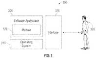
- FIG. 3illustrates a software system 300 , which may be employed for directing the operation of the data-processing systems such as computer system 100 depicted in FIG. 1 .
- Software application 305may be stored in memory 104 , on removable storage 112 , or on non-removable storage 114 shown in FIG. 1 , and generally includes and/or is associated with a kernel or operating system 310 and a shell or interface 315 .
- One or more application programs, such as module(s) or node(s) 125may be “loaded” (i.e., transferred from removable storage 112 into the memory 104 ) for execution by the data-processing system 100 .
- the data-processing system 100can receive user commands and data through user interface 315 , which can include input 116 and output 118 , accessible by a user 320 . These inputs may then be acted upon by the computer system 100 in accordance with instructions from operating system 310 and/or software application 305 and any software module(s) 125 thereof.
- program modulescan include, but are not limited to, routines, subroutines, software applications, programs, objects, components, data structures, etc., that perform particular tasks or implement particular abstract data types and instructions.
- routinese.g., module 125
- program modulescan include, but are not limited to, routines, subroutines, software applications, programs, objects, components, data structures, etc., that perform particular tasks or implement particular abstract data types and instructions.
- program modulese.g., module 125
- program modulese.g., module 125
- program modulese.g., module 125
- routinese.g., routines, subroutines, software applications, programs, objects, components, data structures, etc., that perform particular tasks or implement particular abstract data types and instructions.
- modulese.g., module 125
- routinese.g., routine
- modulemay refer to a collection of routines and data structures that perform a particular task or implements a particular abstract data type. Modules may be composed of two parts: an interface, which lists the constants, data types, variables, and routines that can be accessed by other modules or routines; and an implementation, which is typically private (accessible only to that module) and which includes source code that actually implements the routines in the module.
- the term modulemay also simply refer to an application such as a computer program designed to assist in the performance of a specific task such as word processing, accounting, inventory management, etc., or a hardware component designed to equivalently assist in the performance of a task.
- the interface 315(e.g., a graphical user interface 130 ) can serve to display results, whereupon a user 320 may supply additional inputs or terminate a particular session.
- operating system 310 and GUI 130can be implemented in the context of a “windows” system. It can be appreciated, of course, that other types of systems are possible. For example, rather than a traditional “windows” system, other operation systems such as, for example, a real-time operating system (RTOS) more commonly employed in wireless systems may also be employed with respect to operating system 310 and interface 315 .
- the software application 305can include, for example, module(s) 125 , which can include instructions for carrying out steps or logical operations such as those shown and described herein.
- a system and method for optimized, non-invasive measurement of nuclear magnetic resonance (NMR) relaxometry signals from the distal end of a human fingerare disclosed.
- the embodimentscan be used to monitor an individual's metabolic health by measuring T 2 or T 1 relaxation times of tissues in the fingertip.
- T 2 relaxation timeis a powerful and practical biomarker for monitoring cardio-metabolic health, and detecting, for example, early risk for type 2 diabetes and atherosclerotic cardiovascular disease.
- the methods and systems disclosed hereincan provide metabolic health screening in point-of-care settings, like primary care medical clinics.
- the embodimentsare non-invasive and do not require a blood sample.
- a “sample” used for NMR relaxometry analysiscan be non-invasively taken from the finger (e.g., an index finger, but other fingers could also be used) of a living human being, as opposed to a liquid substance inside of a glass tube.
- the systems disclosedcan generate a profile of the physical and dynamical properties of the molecules in the sample (i.e. the patient's finger). Changes in the motion of the molecules in the sample can be equated with changes in metabolism or metabolic health.
- an NMR relaxometry systemcan comprise a housing, a testing assembly in the housing, and a computer or other such device for reading out results of a test.
- FIG. 4illustrates a system 400 for NMR relaxometry measurement of metabolic health.
- the housingcan include a container formed by a magnet cover 405 .
- the magnet cover 405surrounds a permanent magnet 450 , a heater element coupled electronically to an external temperature regulator (to keep the magnetic field stable), and a probe 495 .
- the probe 495sits in between the north and south poles of the magnet 450 and serves as the interface between the magnet 450 , the transceiver coils 445 and the sample (i.e., a human finger).
- the probe 495can be cylindrical in shape, designed with a diameter to accommodate an average sized human finger (e.g., 20.5 mm, but other diameters can be used in other embodiments).
- the magnet cover 405houses the permanent magnet 450 .
- the permanent magnet 450provides a nearly homogeneous magnetic field across the volume of the probe 495 and, by extension, the test subject's fingertip.
- the magnetic fieldmust be nearly homogenous at the proper depth from the top of the magnet box in order to provide accurate readings. Any remaining field inhomogeneity can be eliminated using a Carr-Purcell-Meiboom-Gill (CPMG) pulse sequence to collect T 2 values.
- CPMGCarr-Purcell-Meiboom-Gill
- the permanent magnet 450provides a homogeneous magnetic field specifically tailored to the geometry of a typical human hand.
- the critical region of the magnetic fieldis larger and closer to the top surface.
- the two magnet blocks 450 and a pole shoescan be placed below the edge of the magnet yoke 425 . This is necessary to provide the optimal depth of the probe 495 to accommodate a human fingertip within the homogeneous magnetic field region, or “sweet spot”.
- the body 420 of the system 400can include one or more handles 410 that can be provided on the exterior of the body 420 .
- the body 420generally includes sidewalls and a top and bottom surface, thereby enclosing the various components of the system 400 .
- One or more standoffs 415can be formed on the bottom surface of the body 420 , which serve to hold the body 420 off the surface on which the system 400 is sitting.
- the systemincludes a cover 430 , which can be formed of plastic, or other such non-magnetic material, and is configured near the top side of the body 420 and extends from the sidewalls along the inside of the body, with a void where the NMR coil holder 435 is formed.
- the NMR coil holder 435can comprise a poly tetrafluoroethylene (PTFE) NMR coil holder or can be comprised of other, similar materials.
- a plastic frame 440can be fitted to the cover 430 and/or the PTFE NMR coil holder 435 to secure the PTFE NMR coil holder in position near the top of the body 420 .
- the NMR coil 445is configured below the PTFE NMR coil holder 435 , and on a NMR coil base 475 , collectively known as the NMR coil assembly.
- the coil base 475can also be a PTFE NMR coil base or can be formed of other similar material.
- HV capacitors 485used to tune the circuit to the proper resonance frequency and impedance, are attached to the cover 430 in proximity to the PTFE NMR coil holder 435 .
- the coil assemblyis covered by a cover assembly 480 that can be formed of brass or other such materials.
- the sensor probe head assembly 500illustrated in FIG. 5 , has a case that can be formed with aluminum or other similar material.
- the system 400is further illustrated in FIG. 5 , where a magnet assembly, including the permanent magnet 450 , is connected to a magnet pole shoe 455 , just exterior to the PTFE NMR coil holder 435 .
- the permanent magnet 450can comprise two blocks (which can be rectangular in some embodiments) made of a rare earth magnet, including the rare earth material Neodymium, or other such powerful permanent magnetic material.
- the materialcan comprise N42, which refers to a grade of neodymium-iron-boron, or NdFeB.
- the dimensions of the magnet blockscan be sized to provide the desired magnetic field. In certain embodiments, this can be 100 ⁇ 100 ⁇ 30 mm, but other dimensions may be necessary according to design considerations.
- the magnet assemblyincludes pole shoes 455 , which serve to support the magnet blocks 450 and disperse the magnetic field with the desired directionality.
- the pole shoes 455can be made, for example, of soft magnetic steel, polished, and annealed at 600 degrees C. in a nitrogen atmosphere, to eliminate mechanical internal strains. Other pole shoes that provide a similar dispersion of the magnetic field can also be used.
- the two magnet blocks 450 and pole shoes 455can be placed 5-10 mm lower than the edge of the magnet yoke 425 . This is necessary to provide the optimal depth of the probe 495 to accommodate a human fingertip within the homogeneous magnetic field region or “sweet spot”.
- the magnet assemblycan be thermally insulated, by an insulator if necessary, and housed within a stainless steel outer shell or body 420 .
- the temperature stability of the magnetis achieved with a standard temperature controller connected to one or more heaters (preferably providing unto to 24 watts), and a standard temperature sensor.
- the temperature controllercan be embodied as software associated with a computer system operably connected to the system 400 as illustrated in FIG. 8 .
- FIG. 5further illustrates a connector panel 460 .
- the connector panel 460includes a heater connection 465 that provides connection to the heater.
- An RF connection 470is provided on the connector panel 460 .
- the RF connection 470can be connected to an external electronics console, which houses an RF transmitter and receiver electronics and an acquisition computer, as further detailed in FIG. 8 .
- This connectorcouples the NMR probe electronics inside the magnet box with the exterior electronics console.
- the connector panel 460can further provide connections to various external devices such as a power supply and/or battery, and a host computer that provides the interface to the user.
- the userinteracts with the instrument through software that implements the NMR pulse sequence, collects data, and analyzes the collected data.
- FIG. 6A top view of the system 400 is illustrated in FIG. 6 .
- the top of the system 400includes a hole 490 , where a test subject's finger can be inserted into the testing space formed in the plastic frame 440 by the PTFE NMR coil holder 435 , NMR coil 445 , and the PTFE NMR coil base 475 .
- the top viewillustrates the top cover, comprising the magnet cover 405 .
- FIG. 7illustrates a more detailed view of the sensor probe head assembly 500 .
- the sensor probe head assembly 500includes the sensor probe head case 485 upon which the PTFE NMR coil holder 430 and plastic frame 440 are mounted.
- the surrounding cover 480is illustrated (detached from the assembly 500 for clarity).
- the PTFE coil holder 475is illustrated.
- FIG. 8illustrates a block diagram of a system 800 in accordance with the disclosed embodiments.
- the system 800includes the system 400 , as described herein, that uses NMR relaxometry analysis to non-invasively sample the finger of a living human being (e.g., without a needle stick) to generate a profile of the physical and dynamical properties of the molecules in the sample (i.e., the patient's finger).
- the RF connection 470 from the systemcan be connected to an external electronics console 805 , which houses an RF transmitter 810 .
- the RF transmitter 810can include receiver electronics and an acquisition computer, which can be embodied as a computer system such as computer system 110 .
- the connector 470couples the NMR probe electronics inside the magnet box as described in system 400 with the electronics console 805 .
- the system 800can be integrated in a single housing or unit.
- the connector panel 460can further provide connection to various external devices such as a power supply 815 , which can be embodied as a wall outlet, battery, or other such power supply.
- a power supply 815which can be embodied as a wall outlet, battery, or other such power supply.
- the integrated computer system 110can provide an interface to the user.
- the userinteracts with the instrument through a software module 125 and GUI.
- the software module 125implements the NMR pulse sequence via the RF transmitter 810 , collects data from the system 400 , and analyzes that data as further disc used herein.
- a key aspect of the disclosed embodimentsis the ability to collect NMR relaxometry data on a living human finger and resolve several T 2 values representing different tissue elements.
- analysis of isolated non-living tissuescan be used as control samples. It should be understood that the dominant components observed in the T 2 profile of the living finger arise from adipose tissue.
- FIG. 9Aillustrates a chart 900 of data that can be collected and provided to a medical practitioner according to the methods and systems disclosed.
- plot 905is a Carr-Purcell-Meiboom-Gill (CPMG) T 2 decay curve.
- CPMGCarr-Purcell-Meiboom-Gill
- the y-axis 910represents NMR signal intensity (i.e., the output voltage) and the x-axis 915 , illustrates decay time.
- a discrete inverse Laplace transformcan be applied to the decay curve in order to extract three individual T 2 components.
- the inset 920indicates the relative intensity (B norm ) and T 2 value (tau, in microseconds) for each of the three components.
- FIG. 9Billustrates chart 950 which graphically depicts the results of the discrete inverse Laplace transform, showing the distribution of the three T 2 components.
- the y-axis 955is relative NMR signal intensity (B norm ), and the x-axis 960 is T 2 .
- the dominant contributor to the left-most peak 965is tendon, while the dominant contributor to the middle peak 970 and right-most peak 975 is adipose tissue.
- the position of these three peaks on the x-axis 960is indicative of the fluidity of that component.
- the higher the T 2 valuethe higher the tissue fluidity.
- Adipose tissueyields two T 2 components representing different mobility domains within that tissue.
- the analysis resultsare thus displayed in the form of an increasing or decaying exponential signal as a function of decay time, as illustrated in FIGS. 9A and 9B .
- the algorithm used for such fittingcan be a discrete inverse Laplace transform but other algorithms can also be used.
- resolution of up to four tissue compartments, such as tendon, adipose tissue, blood and lymph,is possible.
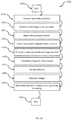
- FIG. 10illustrates a flow chart associated with a method 1000 for measuring metabolic health, according to relaxation variables, using the systems and apparatuses described herein.
- the methodbegins at step 1005 .
- the NMR device 400 and/or system 800can be activated.
- the patientcan insert their finger through a hole into the probe of the device 400 .
- the deviceis ready and the process of taking measurement can begin as illustrated at step 1020 .
- the devicefunctions by introducing the subject's finger to the magnetic field created in the device by permanent magnets as shown at step 1025 .
- the magnetic fieldaligns the magnetic moments of hydrogen atoms in the subject's finger (most notably the hydrogen in the adipose tissue in the subject's finger) with (or against) the permanent magnetic field.
- a radio frequency pulsecan then be applied in a direction that provides a secondary magnetic field perpendicular to the permanent magnetic field. This temporarily changes the magnetic moment of the hydrogen atoms away from their equilibrium state. The change in the magnetic moment, away from equilibrium, is determined by the duration of the pulse.
- the combined realignment of the hydrogen atoms back to their equilibrium stategenerates a small oscillating or non-oscillating magnetic field as shown at step 1035 .
- the changing magnetic fieldin turn induces an alternating voltage in the coil surrounding the subject's finger as shown at step 1040 , which can be measured and reported with a computer, oscilloscope, or other such device as shown at step 1045 .
- the rate of increase or decay of the voltagecan then be equated to a T 1 or T 2 value, which can be used to determine metabolic health at step 1050 .
- the methodends at step 1055 .
- Adipose tissuecontains cells (adipocytes) filled with internal lipid droplets, as well as a fibrous extracellular matrix to provide mechanical support, and blood vessels and other immune cells. As the tissue becomes more fluid, the T 2 value increases. By contrast, more rigidity in the tissue results in a lowering of the T 2 . These changes in tissue fluidity occur with changes in metabolism and metabolic health.
- adipose tissueyields the largest signal. This is a result of the fact that adipose tissue constitutes the largest percentage of the tissue in the distal phalanx of the finger and because it is relatively fluid.
- Adipose tissue fluidity(monitored as adipose tissue T 2 ) is an important measure of metabolic health and disease risk.
- adipose T 2reflects the fatty acid composition of the stored lipids. For example, an individual consuming large amounts of fish or fish oil will have a more fluid adipose tissue and a higher T 2 value compared with those consuming a diet rich in saturated fats.
- T 2isakily sensitive to lipid fluidity, especially as it pertains to omega-3 content.
- Adipose tissue fluidityis also important with respect to inflammation and fibrosis.
- Adipose tissue inflammationis a key driver of early metabolic syndrome—the early metabolic abnormalities that put someone at risk for type 2 diabetes and cardiovascular disease.
- Adipose tissue fibrosiswhich makes the tissue more rigid, is associated with inflammation and would drive the T 2 value lower.
- the disclosed methods, systems, and devicescan screen for early metabolic syndrome.
- the embodimentsprovide a non-invasive, fingertip assessment of metabolic health, measured in about a minute.
- High adipose T 2 and high adipose tissue fluidityis indicative of better metabolic health and lower risk of diabetes or cardiovascular disease.
- low adipose T 2is indicative of poor metabolic health.
- T 2is a marker of adipose tissue inflammation and early metabolic syndrome, where low adipose T 2 also reflects a diet high in saturated fats and low in fish/fish oil. Such diets are associated with increased diabetes and cardiovascular risk.
- a medical testing systemcomprises a housing, at least one magnet assembly configured around a probe configured to accept a human finger, formed in said housing wherein said at least one magnet assembly creates a permanent magnetic field around said probe, an RF signal generator configured to create a temporary magnetic field perpendicular to said permanent magnetic field in said housing, and an NMR coil assembly wherein a change in said permanent magnetic field induces a voltage in said NMR coil assembly.
- the NMR coil assemblyfurther comprises an NMR coil surrounding said probe and a coil base configured to hold said NMR coil.
- the at least one magnet assemblyfurther comprises a permanent magnet mounted in said housing externally to said probe.
- the permanent magnetfurther comprises a rare earth magnet.
- the at least one magnet assemblyfurther comprises a yoke and a magnet pole shoe configured to disperse said permanent magnetic field.
- the medical testing systemfurther comprises a heater configured inside said housing wherein said heater maintains a temperature inside said housing.
- the medical testing systemfurther comprises an output operably connected to said NMR coil assembly wherein said output comprises a non-invasive measurement of at least one of T 2 and T 1 in intact living tissue indicative of at least one of adipose tissue fluidity and metabolic health.
- the an apparatuscomprises a housing, at least one magnet assembly configured around a probe configured to accept a human finger, formed in said housing wherein said at least one magnet assembly creates a permanent magnetic field around said probe, an RF signal generator configured to create a temporary magnetic field perpendicular to said permanent magnetic field in said housing, and an NMR coil assembly wherein a change in said permanent magnetic field induces a voltage in said NMR coil assembly.
- the NMR coil assemblyfurther comprises an NMR coil surrounding said probe and a coil base configured to hold said NMR coil.
- the at least one magnet assemblyfurther comprises a permanent magnet mounted in said housing externally to said probe.
- the permanent magnetfurther comprises a rare earth magnet.
- the at least one magnet assemblyfurther comprises a yoke and a magnet pole shoe configured to disperse said permanent magnetic field.
- the apparatuscomprises a heater configured inside said housing wherein said heater maintains a temperature inside said housing.
- the apparatuscomprises an output operably connected to said NMR coil assembly wherein said output comprises a non-invasive measurement of at least one of T 2 and T 1 in intact living tissue indicative of at least one of: adipose tissue fluidity and metabolic health.
- a medical testing methodcomprises initializing an NMR testing device, inserting a test subject's finger into a test probe, said test probe configured between at least one magnet assembly configured formed in said NMR testing device, generating a permanent magnetic field around said probe, creating a temporary magnetic field perpendicular to said permanent magnetic field in said housing with an RF signal generator, and measuring an induced voltage in an NMR coil assembly resulting from a change in said permanent magnetic field.
- the NMR coil assemblyfurther comprises an NMR coil surrounding said probe and a coil base configured to hold said NMR coil.
- the at least one magnet assemblyfurther comprises a permanent magnet mounted in said housing externally to said probe.
- the methodfurther comprises dispersing said permanent magnetic field with a magnet pole shoe.
- the methodfurther comprises maintaining a temperature inside said NMR testing device with a heater.
- the methodfurther comprises outputting a non-invasive measurement of at least one of T 2 and T 1 in intact living tissue indicative of at least one of: adipose tissue fluidity and metabolic health.
Landscapes
- Physics & Mathematics (AREA)
- Health & Medical Sciences (AREA)
- Life Sciences & Earth Sciences (AREA)
- Condensed Matter Physics & Semiconductors (AREA)
- General Physics & Mathematics (AREA)
- Public Health (AREA)
- Molecular Biology (AREA)
- Veterinary Medicine (AREA)
- Biophysics (AREA)
- Pathology (AREA)
- Engineering & Computer Science (AREA)
- Biomedical Technology (AREA)
- Heart & Thoracic Surgery (AREA)
- Medical Informatics (AREA)
- General Health & Medical Sciences (AREA)
- Surgery (AREA)
- Animal Behavior & Ethology (AREA)
- High Energy & Nuclear Physics (AREA)
- Nuclear Medicine, Radiotherapy & Molecular Imaging (AREA)
- Obesity (AREA)
- Radiology & Medical Imaging (AREA)
- Chemical & Material Sciences (AREA)
- Dispersion Chemistry (AREA)
- Measuring And Recording Apparatus For Diagnosis (AREA)
- Investigating Or Analysing Biological Materials (AREA)
Abstract
Description
Claims (20)
Priority Applications (3)
| Application Number | Priority Date | Filing Date | Title |
|---|---|---|---|
| US15/911,728US10775458B2 (en) | 2018-03-05 | 2018-03-05 | Method and system for non-invasive measurement of metabolic health |
| EP19763830.7AEP3762731A4 (en) | 2018-03-05 | 2019-03-05 | METABOLIC HEALTH METHOD AND SYSTEM FOR NON-INVASIVE MEASUREMENT |
| PCT/IB2019/051772WO2019171275A1 (en) | 2018-03-05 | 2019-03-05 | Method and system for non-invasive measurement of metabolic health |
Applications Claiming Priority (1)
| Application Number | Priority Date | Filing Date | Title |
|---|---|---|---|
| US15/911,728US10775458B2 (en) | 2018-03-05 | 2018-03-05 | Method and system for non-invasive measurement of metabolic health |
Publications (2)
| Publication Number | Publication Date |
|---|---|
| US20190271749A1 US20190271749A1 (en) | 2019-09-05 |
| US10775458B2true US10775458B2 (en) | 2020-09-15 |
Family
ID=67767384
Family Applications (1)
| Application Number | Title | Priority Date | Filing Date |
|---|---|---|---|
| US15/911,728Active2038-08-09US10775458B2 (en) | 2018-03-05 | 2018-03-05 | Method and system for non-invasive measurement of metabolic health |
Country Status (3)
| Country | Link |
|---|---|
| US (1) | US10775458B2 (en) |
| EP (1) | EP3762731A4 (en) |
| WO (1) | WO2019171275A1 (en) |
Families Citing this family (1)
| Publication number | Priority date | Publication date | Assignee | Title |
|---|---|---|---|---|
| US12245849B2 (en) | 2023-08-08 | 2025-03-11 | Synex Medical Inc. | System and method for nuclear magnetic resonance measurement of blood analyte levels |
Citations (47)
| Publication number | Priority date | Publication date | Assignee | Title |
|---|---|---|---|---|
| WO1991004744A1 (en) | 1989-10-06 | 1991-04-18 | The Beth Israel Hospital Association | Methods and apparatus for treating disease states using oxidized lipoproteins |
| WO1991010128A1 (en) | 1989-12-21 | 1991-07-11 | The Beth Israel Hospital Association | Method for predicting atherosclerotic risk |
| US5072732A (en)* | 1986-09-04 | 1991-12-17 | Advanced Techtronics, Inc. | NMR instrument for testing for fluid constituents |
| US5320103A (en)* | 1987-10-07 | 1994-06-14 | Advanced Techtronics, Inc. | Permanent magnet arrangement |
| US5343389A (en) | 1991-07-30 | 1994-08-30 | North Carolina State University | Method and apparatus for measuring classes and subclasses of lipoproteins |
| US5366440A (en) | 1989-10-06 | 1994-11-22 | The Beth Israel Hospital Association | Methods for treating disease states using oxidized lipoproteins in conjunction with chemotherapeutic effector agents |
| WO2000017766A2 (en) | 1998-09-22 | 2000-03-30 | Cybex Computer Products Corporation | System for accessing personal computers remotely |
| WO2000065366A1 (en) | 1999-04-22 | 2000-11-02 | Lipomed, Inc. | Nmr-method for determining the risk of developing type 2 diabetes |
| US20020087276A1 (en) | 1999-02-26 | 2002-07-04 | Otvos James D. | Methods, systems, and computer program products for analyzing and presenting NMR lipoprotein-based risk assessment results |
| US6426058B1 (en) | 1996-03-29 | 2002-07-30 | The Regents Of The University Of California | Enhancement of NMR and MRI in the presence of hyperpolarized noble gases |
| WO2003012416A1 (en) | 2001-08-01 | 2003-02-13 | Liposcience, Inc. | Method of determining presence and concentration of lipoprotein x in blood plasma and serum |
| US20030054599A1 (en) | 2001-08-06 | 2003-03-20 | Huizing Hendrik Gezienus Albert | Bipolar transistor, semiconductor device and method of manufacturing same |
| US6574495B1 (en) | 1997-11-12 | 2003-06-03 | Amersham Health As | Para-hydrogen labelled agents and their use in magnetic resonance imaging |
| US20030119194A1 (en) | 1999-02-26 | 2003-06-26 | Otvos James D. | Methods for providing personalized lipoprotein-based risk assessments |
| US6683455B2 (en) | 2000-12-22 | 2004-01-27 | Metabometrix Limited | Methods for spectral analysis and their applications: spectral replacement |
| US20040098208A1 (en) | 2002-10-25 | 2004-05-20 | Russell Reeve | Methods, systems and computer programs for deconvolving the spectral contribution of chemical constituents with overlapping signals |
| US20040142496A1 (en) | 2001-04-23 | 2004-07-22 | Nicholson Jeremy Kirk | Methods for analysis of spectral data and their applications: atherosclerosis/coronary heart disease |
| US20050222504A1 (en) | 2004-04-01 | 2005-10-06 | Otvos James D | NMR clinical analyzers and related methods, systems, modules and computer program products for clinical evaluation of biosamples |
| US20060104906A1 (en) | 2002-08-29 | 2006-05-18 | Ardenkjaer-Larsen Jan H | Method and apparatus for producing contrast agents for magnetic resonance imaging |
| WO2006076631A2 (en) | 2005-01-14 | 2006-07-20 | Bayer Healthcare Llc | Methods of in vitro analysis using time-domain nmr spectroscopy |
| US20060164084A1 (en) | 2005-01-21 | 2006-07-27 | General Electric Company | Method and system for enabling adaptive measurement of spin-lattice and spin-spin relaxation times |
| US20060183234A1 (en) | 2003-10-23 | 2006-08-17 | Otvos James D | Methods, systems and computer programs for assessing chd risk using adjusted ldl particle number measurements |
| US7191069B2 (en) | 2001-01-15 | 2007-03-13 | Chenomx, Inc. | Automatic identification of compounds in a sample mixture by means of NMR spectroscopy |
| US20070063700A1 (en) | 2003-07-28 | 2007-03-22 | Levitt Malcom H | Nmr spectroscopy using spin states with long lifetimes |
| US20070178598A1 (en) | 2006-01-10 | 2007-08-02 | Liposcience, Inc. | NMR Measurement of Clinically Relevant Ionized Biosample Constituents Such As Ionized Calcium and/or Magnesium |
| US20070264677A1 (en) | 2006-05-10 | 2007-11-15 | Liposcience, Inc. | Methods, systems and computer programs for assessing chd risk using adjusted hdl particle number measurements |
| US7306562B1 (en) | 2004-04-23 | 2007-12-11 | Medical Software, Llc | Medical risk assessment method and program product |
| US20080038829A1 (en) | 2004-06-01 | 2008-02-14 | Lipofit Analytic Ghmbh | Process for the Determination of Lipoproteins in Body Fluids |
| US7397241B2 (en) | 2004-05-05 | 2008-07-08 | Bruker Biospin Gmbh | Method for determining the content of at least one component of a sample by means of a nuclear magnetic resonance pulse spectrometer |
| US20080204014A1 (en) | 2005-01-27 | 2008-08-28 | Herve Desvaux | Method for Enhancing the Nmr Signal of a Liquid Solution |
| WO2009129265A1 (en) | 2008-04-14 | 2009-10-22 | Huntington Medical Research Institutes | Methods and apparatus for pasadena hyperpolarization |
| US7635331B2 (en) | 2004-07-09 | 2009-12-22 | Samsung Electronics Co., Ltd. | Non-invasive blood glucose sensors using a magneto-resonance absorption method and measurement methods thereof |
| US7647234B1 (en) | 1999-03-24 | 2010-01-12 | Berkeley Heartlab, Inc. | Cardiovascular healthcare management system and method |
| US20100039109A1 (en) | 2008-08-15 | 2010-02-18 | Yuesheng Cheng | Methods for determining in situ the viscosity of heavy oil using nuclear magnetic resonance relaxation time measurements |
| US20100100334A1 (en) | 2008-10-20 | 2010-04-22 | Otvos James D | Lipoprotein insulin resistance indexes and related methods, systems and computer programs for generating same |
| US7713744B2 (en) | 2001-11-13 | 2010-05-11 | The Regents Of The University Of California | Determining the risk of cardiovascular disease using ion mobility of lipoproteins |
| US7750633B2 (en) | 2004-07-22 | 2010-07-06 | The Regents Of The University Of California | Low field magnetic resonance imaging |
| US20100219826A1 (en) | 2007-06-18 | 2010-09-02 | Simon Benedict Duckett | Hyperpolaritzation of compounds for nmr, in particular by means of phip |
| US20100225316A1 (en) | 2009-02-25 | 2010-09-09 | Jacob Richard E | Method and apparatus for enhanced in vivo mri imaging |
| US20100233089A1 (en) | 2007-10-05 | 2010-09-16 | Huntington Medical Research Institutes | Imaging of genetic material with magnetic resonance |
| US20100308822A1 (en)* | 2007-11-06 | 2010-12-09 | T2 Biosystems, Inc. | Small Magnet and RF Coil for Magnetic Resonance Relaxometry |
| US20110160563A1 (en) | 2008-02-26 | 2011-06-30 | Glogau Richard G | Diagnostic skin mapping by mrs, mri and other methods |
| US20120029340A1 (en) | 2010-07-30 | 2012-02-02 | Vanderbilt University | System and method for determining mechanical properties of bone structures |
| WO2014071411A1 (en) | 2012-11-05 | 2014-05-08 | Carolyn Slupsky | Determining disease states using biomarker profiles |
| US20150018638A1 (en) | 2012-02-08 | 2015-01-15 | Anatech Advanced Nmr Alorithms Technologies Ltd. | Apparatus and method for non-invasive measurement of blood parameters |
| WO2016127144A1 (en) | 2015-02-06 | 2016-08-11 | University Of North Texas Health Science Center At Fort Worth | Methods and tools for diagnosing insulin resistance and assessing health status usng nmr relaxation times for water |
| US9551768B2 (en) | 2013-03-15 | 2017-01-24 | East Carolina University | NMR method for monitoring changes in the core of lipoprotein particles in metabolism and disease |
Family Cites Families (9)
| Publication number | Priority date | Publication date | Assignee | Title |
|---|---|---|---|---|
| JPS61196145A (en)* | 1985-02-27 | 1986-08-30 | Toshiba Corp | Small magnetic resonance imaging apparatus |
| US4875486A (en)* | 1986-09-04 | 1989-10-24 | Advanced Techtronics, Inc. | Instrument and method for non-invasive in vivo testing for body fluid constituents |
| US6163154A (en)* | 1997-12-23 | 2000-12-19 | Magnetic Diagnostics, Inc. | Small scale NMR spectroscopic apparatus and method |
| US7276997B2 (en)* | 2005-01-29 | 2007-10-02 | General Electric | Apparatus for positioning a non-imaged extremity during a magnetic imaging process |
| JP4576534B2 (en)* | 2006-03-28 | 2010-11-10 | 国立大学法人 筑波大学 | Magnetic resonance imaging apparatus and imaging method |
| JP5784300B2 (en)* | 2010-11-17 | 2015-09-24 | 株式会社東芝 | RF coil apparatus and magnetic resonance imaging apparatus |
| US20160011290A1 (en)* | 2013-05-21 | 2016-01-14 | Victor Iannello | Non-Invasive, In-Vivo Measurement of Blood Constituents Using a Portable Nuclear Magnetic Resonance Device |
| US11344217B2 (en)* | 2013-09-05 | 2022-05-31 | Massachusetts Institute Of Technology | NMR sensor and methods for rapid, non-invasive determination of hydration state or vascular volume of a subject |
| US11439313B2 (en)* | 2016-05-16 | 2022-09-13 | Bitome, Inc. | Small form factor digitally tunable NMR in vivo biometric monitor for metabolic state of a sample |
- 2018
- 2018-03-05USUS15/911,728patent/US10775458B2/enactiveActive
- 2019
- 2019-03-05WOPCT/IB2019/051772patent/WO2019171275A1/ennot_activeCeased
- 2019-03-05EPEP19763830.7Apatent/EP3762731A4/enactivePending
Patent Citations (60)
| Publication number | Priority date | Publication date | Assignee | Title |
|---|---|---|---|---|
| US5072732A (en)* | 1986-09-04 | 1991-12-17 | Advanced Techtronics, Inc. | NMR instrument for testing for fluid constituents |
| US5320103A (en)* | 1987-10-07 | 1994-06-14 | Advanced Techtronics, Inc. | Permanent magnet arrangement |
| US5366440A (en) | 1989-10-06 | 1994-11-22 | The Beth Israel Hospital Association | Methods for treating disease states using oxidized lipoproteins in conjunction with chemotherapeutic effector agents |
| WO1991004744A1 (en) | 1989-10-06 | 1991-04-18 | The Beth Israel Hospital Association | Methods and apparatus for treating disease states using oxidized lipoproteins |
| WO1991010128A1 (en) | 1989-12-21 | 1991-07-11 | The Beth Israel Hospital Association | Method for predicting atherosclerotic risk |
| US5343389A (en) | 1991-07-30 | 1994-08-30 | North Carolina State University | Method and apparatus for measuring classes and subclasses of lipoproteins |
| US6818202B2 (en) | 1996-03-29 | 2004-11-16 | The Regents Of The University Of California | Enhancement of NMR and MRI in the presence of hyperpolarized noble gases |
| US6426058B1 (en) | 1996-03-29 | 2002-07-30 | The Regents Of The University Of California | Enhancement of NMR and MRI in the presence of hyperpolarized noble gases |
| US6574495B1 (en) | 1997-11-12 | 2003-06-03 | Amersham Health As | Para-hydrogen labelled agents and their use in magnetic resonance imaging |
| WO2000017766A2 (en) | 1998-09-22 | 2000-03-30 | Cybex Computer Products Corporation | System for accessing personal computers remotely |
| US6576471B2 (en) | 1999-02-26 | 2003-06-10 | Liposcience, Inc. | Methods, systems, and computer program products for analyzing and presenting NMR lipoprotein-based risk assessment results |
| US20030119194A1 (en) | 1999-02-26 | 2003-06-26 | Otvos James D. | Methods for providing personalized lipoprotein-based risk assessments |
| US6653140B2 (en) | 1999-02-26 | 2003-11-25 | Liposcience, Inc. | Methods for providing personalized lipoprotein-based risk assessments |
| US20020087276A1 (en) | 1999-02-26 | 2002-07-04 | Otvos James D. | Methods, systems, and computer program products for analyzing and presenting NMR lipoprotein-based risk assessment results |
| US7647234B1 (en) | 1999-03-24 | 2010-01-12 | Berkeley Heartlab, Inc. | Cardiovascular healthcare management system and method |
| WO2000065366A1 (en) | 1999-04-22 | 2000-11-02 | Lipomed, Inc. | Nmr-method for determining the risk of developing type 2 diabetes |
| US6518069B1 (en) | 1999-04-22 | 2003-02-11 | Liposcience, Inc. | Methods and computer program products for determining risk of developing type 2 diabetes and other insulin resistance related disorders |
| US6683455B2 (en) | 2000-12-22 | 2004-01-27 | Metabometrix Limited | Methods for spectral analysis and their applications: spectral replacement |
| US7191069B2 (en) | 2001-01-15 | 2007-03-13 | Chenomx, Inc. | Automatic identification of compounds in a sample mixture by means of NMR spectroscopy |
| US20040142496A1 (en) | 2001-04-23 | 2004-07-22 | Nicholson Jeremy Kirk | Methods for analysis of spectral data and their applications: atherosclerosis/coronary heart disease |
| US6617167B2 (en) | 2001-08-01 | 2003-09-09 | Liposcience, Inc. | Method of determining presence and concentration of lipoprotein X in blood plasma and serum |
| WO2003012416A1 (en) | 2001-08-01 | 2003-02-13 | Liposcience, Inc. | Method of determining presence and concentration of lipoprotein x in blood plasma and serum |
| US20030054599A1 (en) | 2001-08-06 | 2003-03-20 | Huizing Hendrik Gezienus Albert | Bipolar transistor, semiconductor device and method of manufacturing same |
| US7713744B2 (en) | 2001-11-13 | 2010-05-11 | The Regents Of The University Of California | Determining the risk of cardiovascular disease using ion mobility of lipoproteins |
| US20060104906A1 (en) | 2002-08-29 | 2006-05-18 | Ardenkjaer-Larsen Jan H | Method and apparatus for producing contrast agents for magnetic resonance imaging |
| US20040098208A1 (en) | 2002-10-25 | 2004-05-20 | Russell Reeve | Methods, systems and computer programs for deconvolving the spectral contribution of chemical constituents with overlapping signals |
| US7243030B2 (en) | 2002-10-25 | 2007-07-10 | Liposcience, Inc. | Methods, systems and computer programs for deconvolving the spectral contribution of chemical constituents with overlapping signals |
| US7474095B2 (en) | 2003-07-28 | 2009-01-06 | University Of Southampton | NMR spectroscopy using spin states with long lifetimes |
| US20070063700A1 (en) | 2003-07-28 | 2007-03-22 | Levitt Malcom H | Nmr spectroscopy using spin states with long lifetimes |
| US7790465B2 (en) | 2003-10-23 | 2010-09-07 | Liposcience, Inc. | Methods, systems and computer programs for assessing CHD risk using adjusted LDL particle number measurements |
| US20060183234A1 (en) | 2003-10-23 | 2006-08-17 | Otvos James D | Methods, systems and computer programs for assessing chd risk using adjusted ldl particle number measurements |
| US20050222504A1 (en) | 2004-04-01 | 2005-10-06 | Otvos James D | NMR clinical analyzers and related methods, systems, modules and computer program products for clinical evaluation of biosamples |
| US7306562B1 (en) | 2004-04-23 | 2007-12-11 | Medical Software, Llc | Medical risk assessment method and program product |
| US7397241B2 (en) | 2004-05-05 | 2008-07-08 | Bruker Biospin Gmbh | Method for determining the content of at least one component of a sample by means of a nuclear magnetic resonance pulse spectrometer |
| US20080038829A1 (en) | 2004-06-01 | 2008-02-14 | Lipofit Analytic Ghmbh | Process for the Determination of Lipoproteins in Body Fluids |
| US7635331B2 (en) | 2004-07-09 | 2009-12-22 | Samsung Electronics Co., Ltd. | Non-invasive blood glucose sensors using a magneto-resonance absorption method and measurement methods thereof |
| US7750633B2 (en) | 2004-07-22 | 2010-07-06 | The Regents Of The University Of California | Low field magnetic resonance imaging |
| US7550971B2 (en) | 2005-01-14 | 2009-06-23 | Bayer Healthcare Llc | Methods of in vitro analysis using time-domain NMR spectroscopy |
| US7940045B2 (en) | 2005-01-14 | 2011-05-10 | Bayer Healthcare Llc | Methods of in-vitro analysis using time-domain NMR spectroscopy |
| US20090219022A1 (en) | 2005-01-14 | 2009-09-03 | Bayer Healthcare Llc | Methods of In-Vitro Analysis Using Time-Domain NMR Spectroscopy |
| WO2006076631A2 (en) | 2005-01-14 | 2006-07-20 | Bayer Healthcare Llc | Methods of in vitro analysis using time-domain nmr spectroscopy |
| US20080088308A1 (en) | 2005-01-14 | 2008-04-17 | Carpenter Scott E | Methods of In Vitro Analysis Using Time-Domain Nmr Spectroscopy |
| US20060164084A1 (en) | 2005-01-21 | 2006-07-27 | General Electric Company | Method and system for enabling adaptive measurement of spin-lattice and spin-spin relaxation times |
| US7564243B2 (en) | 2005-01-27 | 2009-07-21 | Commissariat A L'energie Atomique | Method for enhancing the NMR signal of a liquid solution |
| US20080204014A1 (en) | 2005-01-27 | 2008-08-28 | Herve Desvaux | Method for Enhancing the Nmr Signal of a Liquid Solution |
| US20070178598A1 (en) | 2006-01-10 | 2007-08-02 | Liposcience, Inc. | NMR Measurement of Clinically Relevant Ionized Biosample Constituents Such As Ionized Calcium and/or Magnesium |
| US20070264677A1 (en) | 2006-05-10 | 2007-11-15 | Liposcience, Inc. | Methods, systems and computer programs for assessing chd risk using adjusted hdl particle number measurements |
| US20100219826A1 (en) | 2007-06-18 | 2010-09-02 | Simon Benedict Duckett | Hyperpolaritzation of compounds for nmr, in particular by means of phip |
| US20100233089A1 (en) | 2007-10-05 | 2010-09-16 | Huntington Medical Research Institutes | Imaging of genetic material with magnetic resonance |
| US20100308822A1 (en)* | 2007-11-06 | 2010-12-09 | T2 Biosystems, Inc. | Small Magnet and RF Coil for Magnetic Resonance Relaxometry |
| US20110160563A1 (en) | 2008-02-26 | 2011-06-30 | Glogau Richard G | Diagnostic skin mapping by mrs, mri and other methods |
| WO2009129265A1 (en) | 2008-04-14 | 2009-10-22 | Huntington Medical Research Institutes | Methods and apparatus for pasadena hyperpolarization |
| US20100039109A1 (en) | 2008-08-15 | 2010-02-18 | Yuesheng Cheng | Methods for determining in situ the viscosity of heavy oil using nuclear magnetic resonance relaxation time measurements |
| US20100100334A1 (en) | 2008-10-20 | 2010-04-22 | Otvos James D | Lipoprotein insulin resistance indexes and related methods, systems and computer programs for generating same |
| US20100225316A1 (en) | 2009-02-25 | 2010-09-09 | Jacob Richard E | Method and apparatus for enhanced in vivo mri imaging |
| US20120029340A1 (en) | 2010-07-30 | 2012-02-02 | Vanderbilt University | System and method for determining mechanical properties of bone structures |
| US20150018638A1 (en) | 2012-02-08 | 2015-01-15 | Anatech Advanced Nmr Alorithms Technologies Ltd. | Apparatus and method for non-invasive measurement of blood parameters |
| WO2014071411A1 (en) | 2012-11-05 | 2014-05-08 | Carolyn Slupsky | Determining disease states using biomarker profiles |
| US9551768B2 (en) | 2013-03-15 | 2017-01-24 | East Carolina University | NMR method for monitoring changes in the core of lipoprotein particles in metabolism and disease |
| WO2016127144A1 (en) | 2015-02-06 | 2016-08-11 | University Of North Texas Health Science Center At Fort Worth | Methods and tools for diagnosing insulin resistance and assessing health status usng nmr relaxation times for water |
Non-Patent Citations (17)
| Title |
|---|
| Barkemeyer, J. et al., Heteronuclear Polarization Transfer Using Selective Pulses during Hydrogenation with Parahydrogen, Journal of Magnetic Resonance, Series A (1996) 120:129-132. |
| Bell, J. D. et al., Effects of n-3 fatty acids on the NMR provile of plasma lipoproteins, Journal of Lipid Research (1996) 37:1664-1674. |
| Bubici, S. et al. Inversion of Multi-component FFC-NMR relaxation decays, Stelar (2012) Sep. 26, 3 pages. |
| Choi, G. T. Y. et al., N.m.r. lipid profiles of cells, tissues and body fluids, Biochem. J. (1993) 290:717-721. |
| Cistola, D. P. et al., Compact NMR relaxometry of human blood and blood components, Trends in Analytical Chemistry (2016) 83:53-64. |
| Eaton, G. R. et al., Spin Lattice Relaxation in Solution and Summary of Relaxation Mechanisms, University of Denver Department of Chemistry and Biochemistr, Modern EPR Spectroscopy Euro-Summer School, Retie, Belgium, Dec. 1-2, 2002, 24 pages. |
| Hays, J. H. et al., Effect of a High Saturated Fat and No-Starch Diet on Serum Lipid Subfractions in Patients with Document Atherosclerotic Cardiovascular Disease, Mayo Clin. Proc. (2003) 78:1331-1336. |
| Mallol, R. et al., Human serum/plasma lipoprotein analysis by NMR: Application to the study of diabetic dyslipidemia, Progress in Nuclear Magnetic Resonance Spectroscopy (2013) 70:1-24. |
| Micklander, E. et al., Multivariate Analysis of Time Domain NMR Signals in Relation to Food Quality, Magnetic Resonance in Food Science: Latest Developments (2003) Belton et al. (eds) pp. 239-254. |
| Miller, W. G. et al., Seven Direct Methods for Measuring HDL and LDL Cholesterol Compared with Ultracentrifugation Reference Measurement Procedures, Clin. Chem. (2010) 56(6):977-986. |
| Mo, H. et al., Pre-SAT180, a Simple and Effective Method for Residual Water Suppression, J. Magn. Reson. (2008) 190(1):1-6. |
| Robinson, M. D. et al., Nancofluidity of Fatty Acid Hydrocarbon Chains as Monitored by Benchtop Time-Domain Nuclear Magnetic Resonance, Biochemistry (2014) 53:7515-7522. |
| Spin-lattice relaxation-Wikipedia, printed Mar. 2, 2018, accessed Jan. 21, 2001, 3 pages. |
| Spin-lattice relaxation—Wikipedia, printed Mar. 2, 2018, accessed Jan. 21, 2001, 3 pages. |
| Tang, H. et al., Use of relaxation-edited one-dimensional and two dimensional nuclear magnetic resonance spectroscopy to improved detection of small metabolites in blood plasma, Analytical Biochemistry (2004) 325:260-272. |
| Total Cholesterol Certification Protocol for Manufacturers-Revised, National Reference System for Cholesterol, Oct. 2004, 11 pages. |
| Total Cholesterol Certification Protocol for Manufacturers—Revised, National Reference System for Cholesterol, Oct. 2004, 11 pages. |
Also Published As
| Publication number | Publication date |
|---|---|
| US20190271749A1 (en) | 2019-09-05 |
| WO2019171275A1 (en) | 2019-09-12 |
| EP3762731A1 (en) | 2021-01-13 |
| EP3762731A4 (en) | 2021-12-01 |
Similar Documents
| Publication | Publication Date | Title |
|---|---|---|
| US11540766B2 (en) | Nuclear magnetic resonance systems and methods for noninvasive and in-vivo measurements using a unilateral magnet | |
| US10321845B2 (en) | Magnetic resonance fingerprinting in slices along a one-dimensional extension | |
| US20160011290A1 (en) | Non-Invasive, In-Vivo Measurement of Blood Constituents Using a Portable Nuclear Magnetic Resonance Device | |
| Ma et al. | Trabecular bone imaging using a 3D adiabatic inversion recovery prepared ultrashort TE Cones sequence at 3T | |
| EP1915089B1 (en) | Electric impedance imaging system, method, and computer program | |
| EP2744406B1 (en) | Magnetic resonance method and system for quantifying hepatic fat in humans | |
| Nagel et al. | 39K and 23Na relaxation times and MRI of rat head at 21.1 T | |
| RU2616984C2 (en) | Magnetic resonance (mr) tomography of electrical properties | |
| Müller et al. | Nuclear spin noise imaging | |
| US20120262174A1 (en) | Method for calculating local specific energy absorption rate (sar) in nuclear magnetic resonance | |
| RU2693837C2 (en) | Magnetic-resonance fingerprint method | |
| JP2009504224A5 (en) | ||
| Li et al. | Effects of inversion time on inversion recovery prepared ultrashort echo time (IR‐UTE) imaging of bound and pore water in cortical bone | |
| Wu et al. | Magic angle effect on adiabatic T1ρ imaging of the Achilles tendon using 3D ultrashort echo time cones trajectory | |
| US12127847B2 (en) | Nuclear magnetic resonance systems and methods for noninvasive and in-vivo measurements using a unilateral magnet | |
| Brizi et al. | Bone volume–to–total volume ratio measured in trabecular bone by single‐sided NMR devices | |
| US20200041594A1 (en) | Sub voxel resolution magnetic resonance fingerprinting imaging | |
| Gast et al. | Combined imaging of potassium and sodium in human skeletal muscle tissue at 7 T | |
| WO2018065233A1 (en) | Direct measurement of the b0-off-resonance field during magnetic resonance fingerprinting | |
| Wong et al. | Refined magic-angle coil spinning resonator for nanoliter NMR spectroscopy: enhanced spectral resolution | |
| US8405392B2 (en) | Corrected nuclear magnetic resonance imaging using magnetization transfer | |
| US10775458B2 (en) | Method and system for non-invasive measurement of metabolic health | |
| Ketsiri et al. | T1 relaxation of bound and pore water in cortical bone | |
| Saupe et al. | Diffusion tensor magnetic resonance imaging of the human calf: comparison between 1.5 T and 3.0 T—preliminary results | |
| Deborne et al. | Proton MRS on sub‐microliter volume in rat brain using implantable NMR microcoils |
Legal Events
| Date | Code | Title | Description |
|---|---|---|---|
| FEPP | Fee payment procedure | Free format text:ENTITY STATUS SET TO UNDISCOUNTED (ORIGINAL EVENT CODE: BIG.); ENTITY STATUS OF PATENT OWNER: MICROENTITY | |
| FEPP | Fee payment procedure | Free format text:ENTITY STATUS SET TO SMALL (ORIGINAL EVENT CODE: SMAL); ENTITY STATUS OF PATENT OWNER: MICROENTITY Free format text:ENTITY STATUS SET TO MICRO (ORIGINAL EVENT CODE: MICR); ENTITY STATUS OF PATENT OWNER: MICROENTITY | |
| STPP | Information on status: patent application and granting procedure in general | Free format text:NON FINAL ACTION MAILED | |
| STPP | Information on status: patent application and granting procedure in general | Free format text:FINAL REJECTION MAILED | |
| STPP | Information on status: patent application and granting procedure in general | Free format text:RESPONSE AFTER FINAL ACTION FORWARDED TO EXAMINER | |
| STPP | Information on status: patent application and granting procedure in general | Free format text:NOTICE OF ALLOWANCE MAILED -- APPLICATION RECEIVED IN OFFICE OF PUBLICATIONS | |
| FEPP | Fee payment procedure | Free format text:ENTITY STATUS SET TO MICRO (ORIGINAL EVENT CODE: MICR); ENTITY STATUS OF PATENT OWNER: MICROENTITY | |
| STPP | Information on status: patent application and granting procedure in general | Free format text:PUBLICATIONS -- ISSUE FEE PAYMENT VERIFIED | |
| STCF | Information on status: patent grant | Free format text:PATENTED CASE | |
| FEPP | Fee payment procedure | Free format text:ENTITY STATUS SET TO SMALL (ORIGINAL EVENT CODE: SMAL); ENTITY STATUS OF PATENT OWNER: SMALL ENTITY | |
| MAFP | Maintenance fee payment | Free format text:PAYMENT OF MAINTENANCE FEE, 4TH YR, SMALL ENTITY (ORIGINAL EVENT CODE: M2551); ENTITY STATUS OF PATENT OWNER: SMALL ENTITY Year of fee payment:4 |