US10772722B2 - Polymeric heart valve - Google Patents
Polymeric heart valveDownload PDFInfo
- Publication number
- US10772722B2 US10772722B2US15/492,227US201715492227AUS10772722B2US 10772722 B2US10772722 B2US 10772722B2US 201715492227 AUS201715492227 AUS 201715492227AUS 10772722 B2US10772722 B2US 10772722B2
- Authority
- US
- United States
- Prior art keywords
- leaflets
- valve
- leaflet
- operative
- thicknesses
- Prior art date
- Legal status (The legal status is an assumption and is not a legal conclusion. Google has not performed a legal analysis and makes no representation as to the accuracy of the status listed.)
- Active, expires
Links
Images


Classifications
- A—HUMAN NECESSITIES
- A61—MEDICAL OR VETERINARY SCIENCE; HYGIENE
- A61F—FILTERS IMPLANTABLE INTO BLOOD VESSELS; PROSTHESES; DEVICES PROVIDING PATENCY TO, OR PREVENTING COLLAPSING OF, TUBULAR STRUCTURES OF THE BODY, e.g. STENTS; ORTHOPAEDIC, NURSING OR CONTRACEPTIVE DEVICES; FOMENTATION; TREATMENT OR PROTECTION OF EYES OR EARS; BANDAGES, DRESSINGS OR ABSORBENT PADS; FIRST-AID KITS
- A61F2/00—Filters implantable into blood vessels; Prostheses, i.e. artificial substitutes or replacements for parts of the body; Appliances for connecting them with the body; Devices providing patency to, or preventing collapsing of, tubular structures of the body, e.g. stents
- A61F2/02—Prostheses implantable into the body
- A61F2/24—Heart valves ; Vascular valves, e.g. venous valves; Heart implants, e.g. passive devices for improving the function of the native valve or the heart muscle; Transmyocardial revascularisation [TMR] devices; Valves implantable in the body
- A61F2/2412—Heart valves ; Vascular valves, e.g. venous valves; Heart implants, e.g. passive devices for improving the function of the native valve or the heart muscle; Transmyocardial revascularisation [TMR] devices; Valves implantable in the body with soft flexible valve members, e.g. tissue valves shaped like natural valves
- A61F2/2418—Scaffolds therefor, e.g. support stents
- A—HUMAN NECESSITIES
- A61—MEDICAL OR VETERINARY SCIENCE; HYGIENE
- A61F—FILTERS IMPLANTABLE INTO BLOOD VESSELS; PROSTHESES; DEVICES PROVIDING PATENCY TO, OR PREVENTING COLLAPSING OF, TUBULAR STRUCTURES OF THE BODY, e.g. STENTS; ORTHOPAEDIC, NURSING OR CONTRACEPTIVE DEVICES; FOMENTATION; TREATMENT OR PROTECTION OF EYES OR EARS; BANDAGES, DRESSINGS OR ABSORBENT PADS; FIRST-AID KITS
- A61F2/00—Filters implantable into blood vessels; Prostheses, i.e. artificial substitutes or replacements for parts of the body; Appliances for connecting them with the body; Devices providing patency to, or preventing collapsing of, tubular structures of the body, e.g. stents
- A61F2/02—Prostheses implantable into the body
- A61F2/24—Heart valves ; Vascular valves, e.g. venous valves; Heart implants, e.g. passive devices for improving the function of the native valve or the heart muscle; Transmyocardial revascularisation [TMR] devices; Valves implantable in the body
- A61F2/2412—Heart valves ; Vascular valves, e.g. venous valves; Heart implants, e.g. passive devices for improving the function of the native valve or the heart muscle; Transmyocardial revascularisation [TMR] devices; Valves implantable in the body with soft flexible valve members, e.g. tissue valves shaped like natural valves
- A61F2/2415—Manufacturing methods
- A—HUMAN NECESSITIES
- A61—MEDICAL OR VETERINARY SCIENCE; HYGIENE
- A61F—FILTERS IMPLANTABLE INTO BLOOD VESSELS; PROSTHESES; DEVICES PROVIDING PATENCY TO, OR PREVENTING COLLAPSING OF, TUBULAR STRUCTURES OF THE BODY, e.g. STENTS; ORTHOPAEDIC, NURSING OR CONTRACEPTIVE DEVICES; FOMENTATION; TREATMENT OR PROTECTION OF EYES OR EARS; BANDAGES, DRESSINGS OR ABSORBENT PADS; FIRST-AID KITS
- A61F2250/00—Special features of prostheses classified in groups A61F2/00 - A61F2/26 or A61F2/82 or A61F9/00 or A61F11/00 or subgroups thereof
- A61F2250/0014—Special features of prostheses classified in groups A61F2/00 - A61F2/26 or A61F2/82 or A61F9/00 or A61F11/00 or subgroups thereof having different values of a given property or geometrical feature, e.g. mechanical property or material property, at different locations within the same prosthesis
- A61F2250/0036—Special features of prostheses classified in groups A61F2/00 - A61F2/26 or A61F2/82 or A61F9/00 or A61F11/00 or subgroups thereof having different values of a given property or geometrical feature, e.g. mechanical property or material property, at different locations within the same prosthesis differing in thickness
Definitions
- the present inventiongenerally relates to implantable prosthetic devices, and more particularly, the present invention relates to an implantable prosthetic heart valve and a method for manufacturing thereof.
- VHDvalvular heart disease
- PHYtissue prosthetic heart valves
- the replacement heart valvemay be an artificial device or an animal tissue valve (e.g., bovine pericardium or porcine aortic valve).
- aortic valvesFor example, one type of heart valve which has been the subject of replacement valves are aortic valves.
- artificial (mechanical) heart valvesare not as prevalently used as animal tissue valves.
- One reasonis artificial valves such as polymer PHVs are unsatisfactorily susceptible to damage caused by stresses from flexing and operation during use, i.e., material fatigue. Since 1960, various devices and techniques have been used for replacement valves and delivery or implantation of the valve.
- a prior art trileaflet heart valve 10includes three leaflets 14 , 16 , 18 , and a stent structure 20 having three posts 22 .
- the stent structure 20supports a multilayer composite polymeric membrane that is a flat sheet membrane sewn into the shape of three leaflets 14 , 16 , 18 , each having a uniform thickness.
- the one-piece multilayer composite polymeric membrane of the leaflets 14 , 16 , 18is composed of a porous polymeric structure (e.g. a knit, weave, braid) sandwiched between two outer polymer layers.
- a porous polymeric structuree.g. a knit, weave, braid
- the polymer in the prior artwas a thermoplastic elastomer with low tensile strength and was prone to significant creep.
- the embedded meshwas designed to add strength.
- animal testing the polymercreep exposed the underlying mesh to blood and caused an adverse reaction.
- the above heart valverequires a multilayer composite approach that is undesirably complex to manufacture and expensive. It also does not allow for fine tuning of the leaflet thickness to improve flexibility and durability.
- a disadvantage of using animal tissue in replacement heart valvesis that chemically fixed animal tissue valves require animal tissue sourcing, handling, processing, sterilization and packaging.
- a valve for use in heart valve replacementthat eliminates the need for animal tissue sourcing, handling, processing, sterilization and packaging, and thereby eliminates any risks to patients involved in implanting xenografts. Further, it would be desirable to provide a replacement valve of increased durability which is not dependent on the health and age of the patient. It would further be advantageous to provide a polymeric heart valve, which can decrease the costs for heart valve replacement. Also, a need exists in the art for a prosthetic valve, and for example, specifically a trileaflet valve, which has improved durability and is less susceptible to fatigue stress. Also, a need exists for the reduction or elimination for the need for anticoagulant drug therapy in prosthetic heart valve recipients. Further, it would be desirable for a prosthetic valve to include a polymer PHVs which combines improved durability with low thrombogenicity.
- a polymeric valvewhich may include a heart valve, and also may include a trileaflet heart valve includes a stent having a base and a plurality of outwardly extending posts from the base and equidistant from each other.
- a plurality of leafletseach connected to a corresponding one of the posts at one end, and each of the leaflets connected to the base.
- Each of the leafletshaving an operative end opposite the end connected to the post, and the operative ends of the leaflets being biased in a closed position such that the operative ends abut each other.
- the operative endsare configured to rhythmically open and close in relation to each other, and the leaflets include multiple cross sectional thicknesses at different portions of the leaflets for optimized flexibility and durability.
- FIG. 1is an isometric view of a prior art trileaflet heart valve
- FIG. 2is an isometric view of a leaflet of the prior art valve shown in FIG. 1 depicting the curvature of the leaflet;
- FIG. 3is an isometric view of the prior art heart valve shown in FIG. 1 ;
- FIG. 4is an isometric view of a trileaflet heart valve according to an embodiment of the invention.
- FIG. 5is a perspective view of a leaflet of the heart valve shown in FIG. 4 depicting the curvature of the leaflet;
- FIG. 6is a cross-sectional view of the center of a leaflet showing representative dimensions of the thicknesses of the leaflet along an operative end of the leaflet;
- FIG. 6Ais a side elevational view of another embodiment of a leaflet as compared to FIG. 6 , showing thicknesses of the leaflet along an operative end of the leaflet;
- FIG. 6Bis a side elevational view of another embodiment of a leaflet as compared to FIGS. 6 and 6A , showing thicknesses of the leaflet along an operative end of the leaflet;
- FIG. 6Cis a side elevational view of another embodiment of a leaflet showing thicknesses of the leaflet along an operative end of the leaflet;
- FIG. 7Ais a top view of two of the leaflets of the valve shown in FIG. 4 ;
- FIG. 7Bis an isometric view of the stent shown in FIG. 4 ;
- FIG. 7Cis isometric view of another embodiment of a stent having post inclined outwardly
- FIG. 8is an isometric view of the heart valve shown in FIG. 4 ;
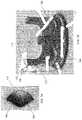
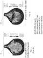
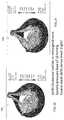
- FIGS. 9-21are color diagrams of embodiment of valves according to the present invention compared to prior art valves depicting stress effects on the leaflets using different colors via finite element analysis using accurate material models based upon valve material uniaxial tensile tests with red being high stress.
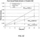
- FIG. 22is a graph showing bulk human platelet activation measurements. Polymer xSIBS valve v. Carpientier-Edwards Perimount Magna tissue valve (benchmark ‘gold standard’ tissue valve).
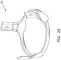
- FIG. 23is an isometric view of the reinforcing frame.
- the heart valve 100includes three leaflets 104 , 106 , 108 .
- the heart valvefurther includes a stent 110 having a circular base 112 and three posts 114 extending outwardly from the base 112 .
- the posts 114are each offset from vertical by 1 mm making an inlet orifice of the valve 19 mm ID, and an outlet orifice 21 mm of the valve. This increases the effective orifice area and reduces the stresses in the leaflets.
- a bottom ridge 113 of the baseextends circumferentially around the base 112 forming the hemispherical bottom ridge 113 .
- the posts 114are positioned in spaced relation to each other to provide a wide stent orifice. The post positioning in the present invention improves hemodynamics as a result of the widened orifice of the stent.
- the heart valve 100is designed to mimic the native aortic valve in form and function.
- the posts 114include a substantially rectangular top portion 115 which has rounded edges.
- the heart valve stent 110has rounded edges for improved hemodynamics, which includes the area at the top of the posts, and the upper edge along the perimeter of the stent.
- the heart valve 100 leaflets 104 , 106 , 108 and the stent 110are injection molded as a single part.
- the leafletsare composed of a singular material, and not constructed from a composite of materials.
- valvesare molded from custom designed molds using a vacuum oven and hot-press for injection molding.
- Computer aided design (CAD) softwaremay be used to create solid models of valve prototypes and valve molds.
- a left heart simulator (LHS)can be used for accurate hydrodynamic assessment of the heart valve for meeting FDA standards.
- An accelerated life cycle testercan be used for durability assessment of the heart valves, such as from Vivitro Labs. Such a machine can simulate 5 years of use in 4 months at 20 Hz.
- a digital particle image velocimetry (DPIV) systemcan be used for the validation of numerical blood analog flow results from the LHS.
- Full prototype platelet activationcan be measured in a small volume flow loop (left ventricular assist) device.
- the valve 100 diameteris variable based upon patient valve dimensions.
- the valve 100may be manufactured in several sizes for a specific patient fit. It is understood that the valve 100 can be manufactured to fit in all nominal human aortic valve positions, in the range of approximately 15-27 mm tissue annulus diameter (TAD). Further, the valve 100 diameter and all other dimensions are proportionally variable based upon patient aortic root dimensions. Thus, all the dimensions of the valve of the present disclosure, may proportionally vary when a different valve size is needed and manufactured, e.g., the leaflets thickness tapering dimensions (which results in cross sectional dimensions shown in FIGS. 6 , 6 A, 6 B, 6 C), will proportionally vary according to the size of the valve, as well as the length and width dimensions of the leaflets and other parts and sections of the valve.
- TADtissue annulus diameter
- valve stent 110may have a metal reinforcing frame 200 embedded for added stiffness where needed.
- Acceptable types of metal for reinforcing the stentmay include, for example, stainless steel.
- the reinforcing frame 200can be fabricated from a biologically compatible material or composite that provides the rigidity of e.g. stainless steel.
- the material of the valveis a polymer that has not been previously applied to prosthetic heart valves.
- the polymermay enhance durability and hemocompatibility over chemically fixed animal tissue and competitive polymers.
- the polymer useful in the manufacture of the valve of the inventionis a formulation provided by Innovia®, LLC Miami, Fla. that is a thermally cross-linkable formulation of their thermoplastic elastomer-poly(styrene-isobutylene-styrene) or SIBS.
- SIBShas physical properties that overlap polyurethane and silicone rubber. SIBS has been shown to be hydrolytically, enzymatically, and oxidatively stable in vivo.
- the infusible and insoluble cross-linkable thermoset formulationis called xSIBS.
- xSIBShas enhanced durability over SIBS because the cross-linking of the polymer chains adds strength and reduces or eliminates creep (time dependent change in strain under a constant load below the yield stress). Altering the ratio of SIBS constituents, styrene and isobutylene, will alter the hardness or softness of the material. In one embodiment, xSIBS may include about 22% styrene. Other polymers may also be applicable in the heart valve of the present invention.
- the valve leaflets 104 , 106 , 108are designed with a customized variable thickness (discussed in greater detail below) for the reduction of high stress concentrations, and with maximized flexibility. Regions of expected high stress are thickened, that is they have a larger cross section or thickness measurement. Regions of expected lower stress are thinned, that is they have a smaller cross section or thickness. Thereby, the leaflets achieve an optimized stress distribution.
- the result of the customized variable thicknesses of the leafletsis improved hemodynamics and high durability.
- the enhanced hemodynamics of the valve 100result in a lower thrombogenic potential.
- Embodiments of the valve according to the present inventionare shown in FIGS. 4, and 8 .
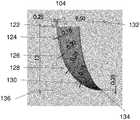
- an operative end 120 of one of the leafletsis depicted wherein the multiple thicknesses of portions of the leaflet are shown.
- the operative end 120includes an edge with a cross sectional area that provides thickness measurements for the related portion of the leaflet.
- the operative end 120generally corresponds to the operative end of leaflet 106 as can be seen in comparison to the valve is FIG. 4 .
- the portions 122 , 134 of the end 120are at the upper most and lower most portions of the end 120 .
- the thicknesses of portions of the leafletare as follows below.
- the thicknesses of the portions 122 , 134are in the range of 0.1 mm to 0.35 mm, and may be about 0.25 mm.
- the thicknesses of portions 122 , 134may be from 0.2 to 0.25 mm with a plus or minus variation of 0.1 mm.
- a reference point 132(representing a longitudinal axis passing through the center of the valve 100 ) is about 9.5 mm from the upper end 122 of the operative end 120 , and the reference point 132 is about 1.3 mm from the lower edge 134 of the operative end 120 . From top to bottom, portion 124 of the operative edge is about 0.18 mm thick; portion 126 is about 0.20 mm thick; portion 128 is about 0.25 mm thick; and portion 130 is about 0.18 mm thick.
- the thicknesses of the operative end 120 regarding portions 126 , 128 , 130may be varied in thickness by plus or minus 0.1 mm from the above thicknesses.
- the leaflets 104 , 106 , 108are curved.
- Leaflets 104 , 108are concave in the same direction so as to fit together as shown in FIG. 4 .
- Leaflet 106is concave in a complimentary direction to leaflet 104 .
- the leafletsmay have a flat profile.
- a flat profileprovides a larger coaptation surface for improved mating of surfaces, which may reduce regurgitation.
- the operative end 120 of on of the leafletsis depicted wherein another embodiment of the multiple thicknesses of portions of the leaflet are shown.
- the portions 122 , 134 of the end 120are at the upper most and lower most portions of the end 120 .
- the thicknesses of the portions 122 , 134may be about 0.15 mm.
- a post point 132(representing the post 114 placement in FIG. 6 ) is about 9 mm from the upper end 122 of the operative end 120 , and the post point 132 is about 12 mm from the lower edge 134 of the operative end 120 . From top to bottom, portion 124 of the operative edge is about 0.08 mm thick; portion 126 is about 0.10 mm thick; portion 128 is about 0.15 mm thick; and portion 130 is about 0.08 mm thick.
- the operative end 120 of on of the leafletsis depicted wherein another embodiment of the multiple thicknesses of portions of the leaflet are shown.
- the portions 122 , 134 of the end 120are at the upper most and lower most portions of the end 120 .
- the thicknesses of the portions 122 , 134may be about 0.35 mm.
- a post point 132(representing the post 114 placement in FIG. 6 ) is about 9 mm from the upper end 122 of the operative end 120 , and the post point 132 is about 12 mm from the lower edge 134 of the operative end 120 . From top to bottom, portion 124 of the operative edge is about 0.28 mm thick; portion 126 is about 0.30 mm thick; portion 128 is about 0.35 mm thick; and portion 130 is about 0.28 mm thick.
- the operative end 120 of on of the leafletsis depicted wherein another embodiment of the multiple thicknesses of portions of the leaflet are shown.
- the portions 122 , 134 of the end 120are at the upper most and lower most portions of the end 120 .
- the thicknesses of the portions 122 , 134may be about 0.2 mm.
- a post point 132(representing the post 114 placement in FIG. 6 ) is about 9 mm from the upper end 122 of the operative end 120 , and the post point 132 is about 12 mm from the lower edge 134 of the operative end 120 . From top to bottom, portion 124 of the operative edge is about 0.20 mm thick; portion 126 is about 0.25 mm thick; portion 128 is about 0.30 mm thick; and portion 130 is about 0.20 mm thick.
- FIG. 7Ashows leaflets 104 , 108 , with leaflet 104 having a 60 degree angle 115 from a midline of the leaflets to an edge of the leaflet 104 .
- FIG. 7Bshows an embodiment of a stent 110 with illustrative dimensions.
- a dimension 154 from top of the stent 110 to the top of the post 114is about 10 mm.
- Dimension 152is from a vertical outer wall of the post 114 to a reference line inside the valve 100 depicted by reference geometry 156 .
- Dimension 164is about 16 mm and extends between the post dimensions, including dimension 152 , following the reference geometry 156 .
- Radius 160shows an approximately 5 mm radial dimension from a post to the top of the stent 110 along a valley portion 158 between two posts 114 .
- an alternative embodiment of a stent 110 A portion of a valve according to the inventionincludes posts 114 being offset from a vertical axis 174 , such that the posts extend outwardly from the vertical axis 174 and at an obtuse angle in relation to the base of the stent 110 A.
- Vertical axis 172passes through the center of the stent, and is shown for reference.
- the heart valve of the present disclosurecan be surgically implanted in the patient via open heart surgery.
- the valvemay replace a valve in the patient using a catheter delivery system, such as transcatheter valve implantation.
- a catheter delivery systemis disclosed in PCT Application number PCT/US2009/035121, international filing date of Feb. 25, 2009, publication number WO/2009/111241.
- the heart valve 100may also be used in a valve in an artificial heart, as well as for traditional open-heart valve implantation of a heart valve replacement in a patient.
- the heart valve 100may also be used in an artificial heart, or in other pulsatile mechanical circulatory support devices (e.g., a left ventricular assist device).
- the present inventionprovides optimized leaflet thickness (geometry), and a improved valve stent geometry.
- the combination of the leaflet geometry, stent geometry, and polymer characteristicsprovides greater valve stent flexibility, and leaflet durability, resulting in improved leaflet thrombogenicity.
- a design methodologyincludes a design, evaluation, and optimization method, which may be called Device Thrombogenicity Emulator (DTE).
- DTEincludes using a combination of state-of-the-art numerical and experimental methods to virtually assess hemodynamics, and then experimentally verify those results with bench top platelet activation studies.
- An example of an optimizing methodology applicable to the present inventionis described in a paper entitled, “Device Thrombogenicity Emulator (DTE)—Design Optimization Methodology for Cardiovascular Devices: A study in two bileaflet MHV designs”; by Xenos et al.; published in the Journal of Biomechanics, 2010. In the DTE method, it is understood that platelets are anucleate cells that contribute to the formation of blood clots.
- the DTE methodemploys two-phase (fluid and particles) computational fluid dynamics in which is simulated blood flow with the addition of thousands of platelet sized particles. Then, the DTE method calculates the stress accumulation on the particles as they pass through the device and extracts dynamic stress history waveforms from selected “hot-spot” regions of high shear stress suspected to cause platelet activation. The dynamic stress history waveforms can be emulated in a Hemodynamic Shearing Device (HSD). A chromogenic assay may be used to measure thrombin generation, which is a key marker of the platelet activation state.
- HSDHemodynamic Shearing Device
- finite element analysismay be used to perform fluid-structure interaction studies to generate information about the structural stress developed in relation to blood flow. All of this information is fed into the design process and can be repeated iteratively until the design is optimized. All numerical work may be three-dimensional using the latest material models, including performing uniaxial tensile testing of xSIBS for input into numerical material models.
- FIGS. 9 and 11show the prior art valve stent with uniform thickness leaflets. Optimized variable thickness leaflets according to the invention are shown in FIG. 10 .
- FIGS. 9 and 10shown simulations which were conducted with identical material models and mesh densities in order to ascertain the effects of the changes in leaflet geometry.
- FIG. 10shows reduced stress concentrations and magnitudes.
- FIG. 11the material model was changed to reflect the prior art composite leaflet design, while in FIG. 10 the material model reflected the new xSIBS.
- the comparison of FIGS. 10 and 11shows the combined effects of material and geometry changes. The result is that the modified leaflet geometry made from xSIBS produced lower stresses.
- FIGS. 9 and 10show simulations which were conducted with identical material models and mesh densities in order to ascertain the effects of the changes in leaflet geometry.
- FIG. 10shows reduced stress concentrations and magnitudes.
- FIG. 11the material model was changed to reflect the prior art composite leaflet design, while in FIG. 10 the material model reflected the new
- FIGS. 16, 17show the effects of a flexible stent on the stress distribution in the leaflets using the prior art stent geometry with both uniform thickness composite leaflets in FIG. 16 with a prior art composite material, compared to customized thickness leaflets with corresponding material models of the present invention of FIG. 17 , with xSIBS material.
- a flexible stent made of xSIBSproduced low stresses.
- Valves shown in FIGS. 18 and 19depict a comparison of stent design changes.
- the stent shown in FIG. 18incorporates some of the features of the present disclosure, and new stent geometries are shown in stent of FIG. 19 .
- Both the valves shown in FIGS. 18 and 19have customized thickness leaflets and the xSIBS material model.
- the new stent design (geometries) shown in FIG. 19produced lower stresses in the leaflets.
- FIGS. 20 and 21show a comparison of stent design changes wherein the stent shown in FIG. 20 .
- Both the stents shown in FIGS. 20 and 21include customized thickness leaflet and the xSIBS material according to the present invention.
- the leaflets of the valvesare in semi-open valve positions.
- the stent design according to the present inventionproduced lower stresses in the leaflets. All numerical results in FIGS. 9-21 are shown with identical stress scales.
- Platelet thrombin generation rateswere measured using a platelet activation state (PAS) assay. Results were compared measurements conducted with 21 mm Carpentier-Edwards Perimount Magna tissue valves mounted in the pulsatile LVAD and to a negative control, in which the LVAD was run without valves.
- PASplatelet activation state
- Platelet activation of the valveswas measured using 120 ml of blood.
- a Berlin pulsatile left ventricular assist device (LVAD)was used to recirculate 250 ml of solution containing freshly isolated human platelets at a concentration of 20,000/ ⁇ l in platelet buffer.
- the systemheld two identical valves mounted inside custom designed valve holders oriented in opposite directions. The inflow and outflow ports were connected with a compliance reservoir.
- the pump ratewas set to 90 BPM with a stroke volume of 65 ml, corresponding to a cardiac output (CO) of 5.85 l/min.
- the systole/diastole ratiowas set to 0.375.
- the recirculation testwas run for 30 min with samples taken in duplicate every 10 min.
- PASplatelet activation state
Landscapes
- Health & Medical Sciences (AREA)
- Engineering & Computer Science (AREA)
- Biomedical Technology (AREA)
- Cardiology (AREA)
- Oral & Maxillofacial Surgery (AREA)
- Transplantation (AREA)
- Heart & Thoracic Surgery (AREA)
- Vascular Medicine (AREA)
- Life Sciences & Earth Sciences (AREA)
- Animal Behavior & Ethology (AREA)
- General Health & Medical Sciences (AREA)
- Public Health (AREA)
- Veterinary Medicine (AREA)
- Manufacturing & Machinery (AREA)
- Prostheses (AREA)
Abstract
Description
Claims (16)
Priority Applications (1)
| Application Number | Priority Date | Filing Date | Title |
|---|---|---|---|
| US15/492,227US10772722B2 (en) | 2011-10-13 | 2017-04-20 | Polymeric heart valve |
Applications Claiming Priority (4)
| Application Number | Priority Date | Filing Date | Title |
|---|---|---|---|
| US201161546832P | 2011-10-13 | 2011-10-13 | |
| PCT/US2012/059845WO2013055977A1 (en) | 2011-10-13 | 2012-10-12 | Polymeric heart valve |
| US201414351455A | 2014-04-11 | 2014-04-11 | |
| US15/492,227US10772722B2 (en) | 2011-10-13 | 2017-04-20 | Polymeric heart valve |
Related Parent Applications (2)
| Application Number | Title | Priority Date | Filing Date |
|---|---|---|---|
| PCT/US2012/059845ContinuationWO2013055977A1 (en) | 2011-10-13 | 2012-10-12 | Polymeric heart valve |
| US14/351,455ContinuationUS9655720B2 (en) | 2011-10-13 | 2012-10-12 | Polymeric heart valve |
Publications (2)
| Publication Number | Publication Date |
|---|---|
| US20170245989A1 US20170245989A1 (en) | 2017-08-31 |
| US10772722B2true US10772722B2 (en) | 2020-09-15 |
Family
ID=48082461
Family Applications (2)
| Application Number | Title | Priority Date | Filing Date |
|---|---|---|---|
| US14/351,455ActiveUS9655720B2 (en) | 2011-10-13 | 2012-10-12 | Polymeric heart valve |
| US15/492,227Active2033-07-08US10772722B2 (en) | 2011-10-13 | 2017-04-20 | Polymeric heart valve |
Family Applications Before (1)
| Application Number | Title | Priority Date | Filing Date |
|---|---|---|---|
| US14/351,455ActiveUS9655720B2 (en) | 2011-10-13 | 2012-10-12 | Polymeric heart valve |
Country Status (3)
| Country | Link |
|---|---|
| US (2) | US9655720B2 (en) |
| EP (1) | EP2765954B1 (en) |
| WO (1) | WO2013055977A1 (en) |
Cited By (1)
| Publication number | Priority date | Publication date | Assignee | Title |
|---|---|---|---|---|
| US20220411141A1 (en)* | 2019-11-07 | 2022-12-29 | Sahar Madanat | A material dispensing device |
Families Citing this family (58)
| Publication number | Priority date | Publication date | Assignee | Title |
|---|---|---|---|---|
| CN102365308B (en) | 2009-01-12 | 2014-03-12 | 马萨诸塞大学卢维尔分校 | Polyisobutylene-based polyurethanes |
| US8579964B2 (en) | 2010-05-05 | 2013-11-12 | Neovasc Inc. | Transcatheter mitral valve prosthesis |
| US9554897B2 (en) | 2011-04-28 | 2017-01-31 | Neovasc Tiara Inc. | Methods and apparatus for engaging a valve prosthesis with tissue |
| US9308087B2 (en) | 2011-04-28 | 2016-04-12 | Neovasc Tiara Inc. | Sequentially deployed transcatheter mitral valve prosthesis |
| EP2765954B1 (en) | 2011-10-13 | 2021-12-22 | The Research Foundation Of State University Of New York | Polymeric heart valve |
| US9345573B2 (en) | 2012-05-30 | 2016-05-24 | Neovasc Tiara Inc. | Methods and apparatus for loading a prosthesis onto a delivery system |
| WO2014081916A2 (en) | 2012-11-21 | 2014-05-30 | University Of Massachusetts | High strength polyisobutylene polyurethanes |
| US9572665B2 (en) | 2013-04-04 | 2017-02-21 | Neovasc Tiara Inc. | Methods and apparatus for delivering a prosthetic valve to a beating heart |
| GB201403454D0 (en) | 2014-02-27 | 2014-04-16 | Cambridge Entpr Ltd | Heart valve |
| US10507101B2 (en) | 2014-10-13 | 2019-12-17 | W. L. Gore & Associates, Inc. | Valved conduit |
| CA3007660A1 (en) | 2015-12-15 | 2017-06-22 | Neovasc Tiara Inc. | Transseptal delivery system |
| US10433952B2 (en) | 2016-01-29 | 2019-10-08 | Neovasc Tiara Inc. | Prosthetic valve for avoiding obstruction of outflow |
| US20190290800A1 (en) | 2016-03-17 | 2019-09-26 | Centro Cardiologico Monzino | Polymers and uses thereof in manufacturing of 'living' heart valves |
| CA3042588A1 (en) | 2016-11-21 | 2018-05-24 | Neovasc Tiara Inc. | Methods and systems for rapid retraction of a transcatheter heart valve delivery system |
| CN110382568B (en) | 2017-03-07 | 2022-03-04 | 心脏起搏器股份公司 | Hydroboration/oxidation of allyl-terminated polyisobutylenes |
| US11406533B2 (en) | 2017-03-17 | 2022-08-09 | W. L. Gore & Associates, Inc. | Integrated aqueous shunt for glaucoma treatment |
| US10835638B2 (en) | 2017-08-17 | 2020-11-17 | Cardiac Pacemakers, Inc. | Photocrosslinked polymers for enhanced durability |
| CA3073834A1 (en) | 2017-08-25 | 2019-02-28 | Neovasc Tiara Inc. | Sequentially deployed transcatheter mitral valve prosthesis |
| CN111818875B (en) | 2017-10-31 | 2024-05-14 | 爱德华兹生命科学公司 | Valved pipe |
| EP3740253B1 (en) | 2018-01-17 | 2023-08-16 | Cardiac Pacemakers, Inc. | End-capped polyisobutylene polyurethane |
| WO2019195860A2 (en) | 2018-04-04 | 2019-10-10 | Vdyne, Llc | Devices and methods for anchoring transcatheter heart valve |
| PL238746B1 (en) | 2018-07-24 | 2021-09-27 | American Heart Of Poland Spolka Akcyjna | Method of forming prefabricated elements used in the production of transcatheter aortic valve implantation systems and prefabricated aortic valve |
| WO2020047221A1 (en) | 2018-08-29 | 2020-03-05 | W. L. Gore & Associates, Inc. | Drug therapy delivery systems and methods |
| US11278437B2 (en) | 2018-12-08 | 2022-03-22 | Vdyne, Inc. | Compression capable annular frames for side delivery of transcatheter heart valve replacement |
| US11344413B2 (en) | 2018-09-20 | 2022-05-31 | Vdyne, Inc. | Transcatheter deliverable prosthetic heart valves and methods of delivery |
| US10321995B1 (en) | 2018-09-20 | 2019-06-18 | Vdyne, Llc | Orthogonally delivered transcatheter heart valve replacement |
| US11071627B2 (en) | 2018-10-18 | 2021-07-27 | Vdyne, Inc. | Orthogonally delivered transcatheter heart valve frame for valve in valve prosthesis |
| US10595994B1 (en) | 2018-09-20 | 2020-03-24 | Vdyne, Llc | Side-delivered transcatheter heart valve replacement |
| US12186187B2 (en) | 2018-09-20 | 2025-01-07 | Vdyne, Inc. | Transcatheter deliverable prosthetic heart valves and methods of delivery |
| US11109969B2 (en) | 2018-10-22 | 2021-09-07 | Vdyne, Inc. | Guidewire delivery of transcatheter heart valve |
| USD977642S1 (en) | 2018-10-29 | 2023-02-07 | W. L. Gore & Associates, Inc. | Pulmonary valve conduit |
| CN113271890B (en) | 2018-11-08 | 2024-08-30 | 内奥瓦斯克迪亚拉公司 | Ventricular deployment of transcatheter mitral valve prosthesis |
| US11678983B2 (en) | 2018-12-12 | 2023-06-20 | W. L. Gore & Associates, Inc. | Implantable component with socket |
| US10653522B1 (en) | 2018-12-20 | 2020-05-19 | Vdyne, Inc. | Proximal tab for side-delivered transcatheter heart valve prosthesis |
| US11253359B2 (en) | 2018-12-20 | 2022-02-22 | Vdyne, Inc. | Proximal tab for side-delivered transcatheter heart valves and methods of delivery |
| WO2020146842A1 (en) | 2019-01-10 | 2020-07-16 | Vdyne, Llc | Anchor hook for side-delivery transcatheter heart valve prosthesis |
| US11273032B2 (en) | 2019-01-26 | 2022-03-15 | Vdyne, Inc. | Collapsible inner flow control component for side-deliverable transcatheter heart valve prosthesis |
| US11185409B2 (en) | 2019-01-26 | 2021-11-30 | Vdyne, Inc. | Collapsible inner flow control component for side-delivered transcatheter heart valve prosthesis |
| GB201902717D0 (en) | 2019-02-28 | 2019-04-17 | Univ Bristol | Heart valve |
| WO2020181154A2 (en) | 2019-03-05 | 2020-09-10 | Vdyne, Inc. | Tricuspid regurgitation control devices for orthogonal transcatheter heart valve prosthesis |
| CA3132873A1 (en) | 2019-03-08 | 2020-09-17 | Neovasc Tiara Inc. | Retrievable prosthesis delivery system |
| US11173027B2 (en) | 2019-03-14 | 2021-11-16 | Vdyne, Inc. | Side-deliverable transcatheter prosthetic valves and methods for delivering and anchoring the same |
| US10758346B1 (en) | 2019-03-14 | 2020-09-01 | Vdyne, Inc. | A2 clip for side-delivered transcatheter mitral valve prosthesis |
| US10631983B1 (en) | 2019-03-14 | 2020-04-28 | Vdyne, Inc. | Distal subannular anchoring tab for side-delivered transcatheter valve prosthesis |
| US11076956B2 (en) | 2019-03-14 | 2021-08-03 | Vdyne, Inc. | Proximal, distal, and anterior anchoring tabs for side-delivered transcatheter mitral valve prosthesis |
| CA3135753C (en) | 2019-04-01 | 2023-10-24 | Neovasc Tiara Inc. | Controllably deployable prosthetic valve |
| US11491006B2 (en) | 2019-04-10 | 2022-11-08 | Neovasc Tiara Inc. | Prosthetic valve with natural blood flow |
| CA3138875A1 (en) | 2019-05-04 | 2020-11-12 | Vdyne, Inc. | Cinch device and method for deployment of a side-delivered prosthetic heart valve in a native annulus |
| US11779742B2 (en) | 2019-05-20 | 2023-10-10 | Neovasc Tiara Inc. | Introducer with hemostasis mechanism |
| JP7520897B2 (en) | 2019-06-20 | 2024-07-23 | ニオバスク ティアラ インコーポレイテッド | Thin prosthetic mitral valve |
| EP4480458A3 (en) | 2019-08-20 | 2025-04-09 | Vdyne, Inc. | Delivery devices for side-deliverable transcatheter prosthetic valves |
| CN120531525A (en) | 2019-08-26 | 2025-08-26 | 维迪内股份有限公司 | Laterally deliverable transcatheter prosthetic valve and method for its delivery and anchoring |
| US11234813B2 (en) | 2020-01-17 | 2022-02-01 | Vdyne, Inc. | Ventricular stability elements for side-deliverable prosthetic heart valves and methods of delivery |
| US20240108462A1 (en)* | 2022-10-04 | 2024-04-04 | Medtronic Vascular, Inc. | Valve prosthesis having robust prosthetic valve and method |
| CN116509602B (en)* | 2023-05-31 | 2024-02-06 | 苏州心岭迈德医疗科技有限公司 | Polymer heart valve and preparation method thereof |
| CN116849873A (en)* | 2023-07-17 | 2023-10-10 | 苏州心岭迈德医疗科技有限公司 | Artificial high molecular heart valve |
| CN116687625B (en)* | 2023-08-08 | 2023-11-03 | 上海心纪元医疗科技有限公司 | Bracket for polymer valve and manufacturing method thereof |
| GB202400525D0 (en) | 2024-01-15 | 2024-02-28 | Cambridge Entpr Ltd | Apparatus |
Citations (20)
| Publication number | Priority date | Publication date | Assignee | Title |
|---|---|---|---|---|
| US4222126A (en)* | 1978-12-14 | 1980-09-16 | The United States Of America As Represented By The Secretary Of The Department Of Health, Education & Welfare | Unitized three leaflet heart valve |
| SU1144216A1 (en) | 1982-06-30 | 1987-10-07 | Институт Механики Полимеров Ан Латвсср | Mitral valve prosthesis |
| WO1993018721A1 (en) | 1992-03-25 | 1993-09-30 | The University Of Leeds | Artificial heart valve |
| US5549665A (en)* | 1993-06-18 | 1996-08-27 | London Health Association | Bioprostethic valve |
| WO1998032400A1 (en) | 1997-01-24 | 1998-07-30 | Aortech Europe Limited | Heart valve prosthesis |
| WO2001005334A1 (en) | 1999-07-19 | 2001-01-25 | Sulzer Carbomedics Inc. | Heart valve leaflet with reinforced free margin |
| WO2002024119A1 (en)* | 2000-09-21 | 2002-03-28 | St. Jude Medical, Inc. | Valved prostheses with reinforced polymer leaflets |
| US20020045936A1 (en) | 1999-04-16 | 2002-04-18 | Riyad Moe | Heart valve leaflet |
| WO2002100301A1 (en) | 2001-06-13 | 2002-12-19 | Aortech Europe Limited | Heat valve prosthesis and method of manufacture |
| US20030078652A1 (en) | 2001-10-23 | 2003-04-24 | Sutherland Fraser W.H. | Heart valve prosthesis |
| US20030097175A1 (en) | 1999-12-08 | 2003-05-22 | O'connor Bernard | Heart valve prosthesis and method of manufacture |
| US20030114924A1 (en) | 2001-12-18 | 2003-06-19 | Riyad Moe | Polymer heart valve |
| US6953332B1 (en) | 2000-11-28 | 2005-10-11 | St. Jude Medical, Inc. | Mandrel for use in forming valved prostheses having polymer leaflets by dip coating |
| US20060241744A1 (en) | 2003-03-20 | 2006-10-26 | Aortech International Plc | Valve |
| US20070118210A1 (en)* | 2005-11-18 | 2007-05-24 | Leonard Pinchuk | Trileaflet Heart Valve |
| US20070154513A1 (en) | 2005-12-30 | 2007-07-05 | Liliana Atanasoska | Medical devices having multiple charged layers |
| WO2009111241A2 (en) | 2008-02-29 | 2009-09-11 | The Florida International University Board Of Trustees | Catheter deliverable artificial multi-leaflet heart valve prosthesis and intravascular delivery system for a catheter deliverable heart valve prosthesis |
| US20110257738A1 (en) | 2010-04-16 | 2011-10-20 | Abiomed, Inc. | Flow optimized polymeric heart valve |
| US20120065729A1 (en) | 2010-09-10 | 2012-03-15 | Rafael Pintor | Systems and methods for rapidly deploying surgical heart valves |
| US20140303724A1 (en) | 2011-10-13 | 2014-10-09 | The Research Foundation Of State University Of New York | Polymeric heart valve |
Family Cites Families (1)
| Publication number | Priority date | Publication date | Assignee | Title |
|---|---|---|---|---|
| WO2013112298A1 (en) | 2012-01-27 | 2013-08-01 | Wake Forest University | Electroluminescent devices and applications thereof |
- 2012
- 2012-10-12EPEP12840473.8Apatent/EP2765954B1/enactiveActive
- 2012-10-12WOPCT/US2012/059845patent/WO2013055977A1/enactiveApplication Filing
- 2012-10-12USUS14/351,455patent/US9655720B2/enactiveActive
- 2017
- 2017-04-20USUS15/492,227patent/US10772722B2/enactiveActive
Patent Citations (20)
| Publication number | Priority date | Publication date | Assignee | Title |
|---|---|---|---|---|
| US4222126A (en)* | 1978-12-14 | 1980-09-16 | The United States Of America As Represented By The Secretary Of The Department Of Health, Education & Welfare | Unitized three leaflet heart valve |
| SU1144216A1 (en) | 1982-06-30 | 1987-10-07 | Институт Механики Полимеров Ан Латвсср | Mitral valve prosthesis |
| WO1993018721A1 (en) | 1992-03-25 | 1993-09-30 | The University Of Leeds | Artificial heart valve |
| US5549665A (en)* | 1993-06-18 | 1996-08-27 | London Health Association | Bioprostethic valve |
| WO1998032400A1 (en) | 1997-01-24 | 1998-07-30 | Aortech Europe Limited | Heart valve prosthesis |
| US20020045936A1 (en) | 1999-04-16 | 2002-04-18 | Riyad Moe | Heart valve leaflet |
| WO2001005334A1 (en) | 1999-07-19 | 2001-01-25 | Sulzer Carbomedics Inc. | Heart valve leaflet with reinforced free margin |
| US20030097175A1 (en) | 1999-12-08 | 2003-05-22 | O'connor Bernard | Heart valve prosthesis and method of manufacture |
| WO2002024119A1 (en)* | 2000-09-21 | 2002-03-28 | St. Jude Medical, Inc. | Valved prostheses with reinforced polymer leaflets |
| US6953332B1 (en) | 2000-11-28 | 2005-10-11 | St. Jude Medical, Inc. | Mandrel for use in forming valved prostheses having polymer leaflets by dip coating |
| WO2002100301A1 (en) | 2001-06-13 | 2002-12-19 | Aortech Europe Limited | Heat valve prosthesis and method of manufacture |
| US20030078652A1 (en) | 2001-10-23 | 2003-04-24 | Sutherland Fraser W.H. | Heart valve prosthesis |
| US20030114924A1 (en) | 2001-12-18 | 2003-06-19 | Riyad Moe | Polymer heart valve |
| US20060241744A1 (en) | 2003-03-20 | 2006-10-26 | Aortech International Plc | Valve |
| US20070118210A1 (en)* | 2005-11-18 | 2007-05-24 | Leonard Pinchuk | Trileaflet Heart Valve |
| US20070154513A1 (en) | 2005-12-30 | 2007-07-05 | Liliana Atanasoska | Medical devices having multiple charged layers |
| WO2009111241A2 (en) | 2008-02-29 | 2009-09-11 | The Florida International University Board Of Trustees | Catheter deliverable artificial multi-leaflet heart valve prosthesis and intravascular delivery system for a catheter deliverable heart valve prosthesis |
| US20110257738A1 (en) | 2010-04-16 | 2011-10-20 | Abiomed, Inc. | Flow optimized polymeric heart valve |
| US20120065729A1 (en) | 2010-09-10 | 2012-03-15 | Rafael Pintor | Systems and methods for rapidly deploying surgical heart valves |
| US20140303724A1 (en) | 2011-10-13 | 2014-10-09 | The Research Foundation Of State University Of New York | Polymeric heart valve |
Non-Patent Citations (6)
| Title |
|---|
| European Office Action dated May 25, 2018 received in European Patent Application No. 12 840 473.8. |
| Final U.S. Office Action dated Dec. 30, 2015 received in U.S. Appl. No. 14/351,455. |
| International Search Report dated Jan. 17, 2013 received in International Application No. PCT/US2012/059845. |
| Supplementary European Search Report dated Feb. 27, 2015 received in European Application No. 12 84 0473.8. |
| U.S. Office Action dated May 25, 2016 received in U.S. Appl. No. 14/351,455. |
| U.S. Office Action dated May 5, 2015 received in U.S. Appl. No. 14/351,455. |
Cited By (1)
| Publication number | Priority date | Publication date | Assignee | Title |
|---|---|---|---|---|
| US20220411141A1 (en)* | 2019-11-07 | 2022-12-29 | Sahar Madanat | A material dispensing device |
Also Published As
| Publication number | Publication date |
|---|---|
| EP2765954A1 (en) | 2014-08-20 |
| US9655720B2 (en) | 2017-05-23 |
| US20170245989A1 (en) | 2017-08-31 |
| EP2765954A4 (en) | 2015-04-01 |
| WO2013055977A1 (en) | 2013-04-18 |
| EP2765954B1 (en) | 2021-12-22 |
| US20140303724A1 (en) | 2014-10-09 |
Similar Documents
| Publication | Publication Date | Title |
|---|---|---|
| US10772722B2 (en) | Polymeric heart valve | |
| CA1232407A (en) | Bubble heart valve | |
| US20090112309A1 (en) | Collapsible Heart Valve with Polymer Leaflets | |
| Rahmani et al. | Manufacturing and hydrodynamic assessment of a novel aortic valve made of a new nanocomposite polymer | |
| Labrosse et al. | Geometric modeling of functional trileaflet aortic valves: development and clinical applications | |
| JP2009505731A (en) | Four-leaflet stented mitral heart valve | |
| Durko et al. | Characteristics of surgical prosthetic heart valves and problems around labeling: a document from the European Association for Cardio-Thoracic Surgery (EACTS)—the Society of Thoracic Surgeons (STS)—American Association for Thoracic Surgery (AATS) valve labelling task force | |
| CN108135695A (en) | A kind of mitral of native configurations | |
| JP7673923B2 (en) | Methods for manufacturing personalized natural design mitral valve prostheses | |
| CN103961192B (en) | A polymer prosthetic aortic valve | |
| Feng et al. | An in vitro feasibility study of the influence of configurations and leaflet thickness on the hydrodynamics of deformed transcatheter aortic valve | |
| Zhu et al. | Numerical and in-vitro experimental assessment of the performance of a novel designed expanded-polytetrafluoroethylene stentless bi-leaflet valve for aortic valve replacement | |
| Black et al. | Mechanical and other problems of artificial valves | |
| Wu et al. | A review of polymeric heart valves leaflet geometric configuration and structural optimization | |
| Fríes et al. | Structural study of a polymeric aortic valve prosthesis. Analysis for a hyperelastic material | |
| US12202202B2 (en) | Method for manufacturing personalized naturally designed mitral prosthesis | |
| Gallocher | Durability assessment of polymer trileaflet heart valves | |
| Huang | Micromechanical simulations of heart valve tissues | |
| Zhu et al. | An axis-specific mitral annuloplasty ring eliminates mitral regurgitation allowing mitral annular motion in an ovine model | |
| Ramaswamy et al. | Hydrodynamic assessment of aortic valves prepared from porcine small intestinal submucosa | |
| Jeevan et al. | Structural Analysis to Evaluate the Design of a Synthetic Mitral Valve Prosthesis | |
| Sebastian et al. | Influence of leaflet geometry on hydrodynamic performance of transcatheter aortic valve prostheses | |
| Whiting | An investigation into computational modelling strategies to predict the in vitro performance of aortic valve replacements | |
| Walker et al. | Development and in vitro assessment of a new two-leaflet replacement heart valve designed using computer-generated bubble surfaces | |
| Heitkemper | The Development of Computational Methods and Device Design Considerations Towards Improving Transcatheter Heart Valve Engineering |
Legal Events
| Date | Code | Title | Description |
|---|---|---|---|
| FEPP | Fee payment procedure | Free format text:PETITION RELATED TO MAINTENANCE FEES GRANTED (ORIGINAL EVENT CODE: PTGR); ENTITY STATUS OF PATENT OWNER: SMALL ENTITY | |
| STPP | Information on status: patent application and granting procedure in general | Free format text:NON FINAL ACTION MAILED | |
| STPP | Information on status: patent application and granting procedure in general | Free format text:RESPONSE TO NON-FINAL OFFICE ACTION ENTERED AND FORWARDED TO EXAMINER | |
| STPP | Information on status: patent application and granting procedure in general | Free format text:FINAL REJECTION MAILED | |
| AS | Assignment | Owner name:NATIONAL INSTITUTES OF HEALTH (NIH), U.S. DEPT. OF Free format text:CONFIRMATORY LICENSE;ASSIGNOR:STATE UNIVERSITY NEW YORK STONY BROOK;REEL/FRAME:051242/0841 Effective date:20180904 Owner name:NATIONAL INSTITUTES OF HEALTH (NIH), U.S. DEPT. OF HEALTH AND HUMAN SERVICES (DHHS), U.S. GOVERNMENT, MARYLAND Free format text:CONFIRMATORY LICENSE;ASSIGNOR:STATE UNIVERSITY NEW YORK STONY BROOK;REEL/FRAME:051242/0841 Effective date:20180904 | |
| STPP | Information on status: patent application and granting procedure in general | Free format text:RESPONSE AFTER FINAL ACTION FORWARDED TO EXAMINER | |
| STPP | Information on status: patent application and granting procedure in general | Free format text:ADVISORY ACTION MAILED | |
| STPP | Information on status: patent application and granting procedure in general | Free format text:DOCKETED NEW CASE - READY FOR EXAMINATION | |
| STPP | Information on status: patent application and granting procedure in general | Free format text:NOTICE OF ALLOWANCE MAILED -- APPLICATION RECEIVED IN OFFICE OF PUBLICATIONS | |
| STPP | Information on status: patent application and granting procedure in general | Free format text:PUBLICATIONS -- ISSUE FEE PAYMENT VERIFIED | |
| STCF | Information on status: patent grant | Free format text:PATENTED CASE | |
| MAFP | Maintenance fee payment | Free format text:PAYMENT OF MAINTENANCE FEE, 4TH YR, SMALL ENTITY (ORIGINAL EVENT CODE: M2551); ENTITY STATUS OF PATENT OWNER: SMALL ENTITY Year of fee payment:4 |