US10772667B2 - Bone screw with cutting tip - Google Patents
Bone screw with cutting tipDownload PDFInfo
- Publication number
- US10772667B2 US10772667B2US15/852,310US201715852310AUS10772667B2US 10772667 B2US10772667 B2US 10772667B2US 201715852310 AUS201715852310 AUS 201715852310AUS 10772667 B2US10772667 B2US 10772667B2
- Authority
- US
- United States
- Prior art keywords
- distal
- facing surface
- bone
- bone screw
- screw
- Prior art date
- Legal status (The legal status is an assumption and is not a legal conclusion. Google has not performed a legal analysis and makes no representation as to the accuracy of the status listed.)
- Active, expires
Links
Images


Classifications
- A—HUMAN NECESSITIES
- A61—MEDICAL OR VETERINARY SCIENCE; HYGIENE
- A61B—DIAGNOSIS; SURGERY; IDENTIFICATION
- A61B17/00—Surgical instruments, devices or methods
- A61B17/56—Surgical instruments or methods for treatment of bones or joints; Devices specially adapted therefor
- A61B17/58—Surgical instruments or methods for treatment of bones or joints; Devices specially adapted therefor for osteosynthesis, e.g. bone plates, screws or setting implements
- A61B17/68—Internal fixation devices, including fasteners and spinal fixators, even if a part thereof projects from the skin
- A61B17/84—Fasteners therefor or fasteners being internal fixation devices
- A61B17/86—Pins or screws or threaded wires; nuts therefor
- A61B17/8625—Shanks, i.e. parts contacting bone tissue
- A—HUMAN NECESSITIES
- A61—MEDICAL OR VETERINARY SCIENCE; HYGIENE
- A61B—DIAGNOSIS; SURGERY; IDENTIFICATION
- A61B17/00—Surgical instruments, devices or methods
- A61B17/56—Surgical instruments or methods for treatment of bones or joints; Devices specially adapted therefor
- A61B17/58—Surgical instruments or methods for treatment of bones or joints; Devices specially adapted therefor for osteosynthesis, e.g. bone plates, screws or setting implements
- A61B17/68—Internal fixation devices, including fasteners and spinal fixators, even if a part thereof projects from the skin
- A61B17/84—Fasteners therefor or fasteners being internal fixation devices
- A61B17/86—Pins or screws or threaded wires; nuts therefor
- A61B17/864—Pins or screws or threaded wires; nuts therefor hollow, e.g. with socket or cannulated
- A—HUMAN NECESSITIES
- A61—MEDICAL OR VETERINARY SCIENCE; HYGIENE
- A61B—DIAGNOSIS; SURGERY; IDENTIFICATION
- A61B17/00—Surgical instruments, devices or methods
- A61B17/56—Surgical instruments or methods for treatment of bones or joints; Devices specially adapted therefor
- A61B17/58—Surgical instruments or methods for treatment of bones or joints; Devices specially adapted therefor for osteosynthesis, e.g. bone plates, screws or setting implements
- A61B17/68—Internal fixation devices, including fasteners and spinal fixators, even if a part thereof projects from the skin
- A61B17/70—Spinal positioners or stabilisers, e.g. stabilisers comprising fluid filler in an implant
- A61B17/7001—Screws or hooks combined with longitudinal elements which do not contact vertebrae
- A61B17/7035—Screws or hooks, wherein a rod-clamping part and a bone-anchoring part can pivot relative to each other
- A—HUMAN NECESSITIES
- A61—MEDICAL OR VETERINARY SCIENCE; HYGIENE
- A61B—DIAGNOSIS; SURGERY; IDENTIFICATION
- A61B17/00—Surgical instruments, devices or methods
- A61B17/56—Surgical instruments or methods for treatment of bones or joints; Devices specially adapted therefor
- A61B17/58—Surgical instruments or methods for treatment of bones or joints; Devices specially adapted therefor for osteosynthesis, e.g. bone plates, screws or setting implements
- A61B17/68—Internal fixation devices, including fasteners and spinal fixators, even if a part thereof projects from the skin
- A61B17/70—Spinal positioners or stabilisers, e.g. stabilisers comprising fluid filler in an implant
- A61B17/7074—Tools specially adapted for spinal fixation operations other than for bone removal or filler handling
- A61B17/7083—Tools for guidance or insertion of tethers, rod-to-anchor connectors, rod-to-rod connectors, or longitudinal elements
- A61B17/7085—Tools for guidance or insertion of tethers, rod-to-anchor connectors, rod-to-rod connectors, or longitudinal elements for insertion of a longitudinal element down one or more hollow screw or hook extensions, i.e. at least a part of the element within an extension has a component of movement parallel to the extension's axis
- A—HUMAN NECESSITIES
- A61—MEDICAL OR VETERINARY SCIENCE; HYGIENE
- A61B—DIAGNOSIS; SURGERY; IDENTIFICATION
- A61B17/00—Surgical instruments, devices or methods
- A61B17/56—Surgical instruments or methods for treatment of bones or joints; Devices specially adapted therefor
- A61B17/58—Surgical instruments or methods for treatment of bones or joints; Devices specially adapted therefor for osteosynthesis, e.g. bone plates, screws or setting implements
- A61B17/68—Internal fixation devices, including fasteners and spinal fixators, even if a part thereof projects from the skin
- A61B17/84—Fasteners therefor or fasteners being internal fixation devices
- A61B17/86—Pins or screws or threaded wires; nuts therefor
- A61B17/8605—Heads, i.e. proximal ends projecting from bone
- A—HUMAN NECESSITIES
- A61—MEDICAL OR VETERINARY SCIENCE; HYGIENE
- A61B—DIAGNOSIS; SURGERY; IDENTIFICATION
- A61B17/00—Surgical instruments, devices or methods
- A61B17/56—Surgical instruments or methods for treatment of bones or joints; Devices specially adapted therefor
- A61B17/58—Surgical instruments or methods for treatment of bones or joints; Devices specially adapted therefor for osteosynthesis, e.g. bone plates, screws or setting implements
- A61B17/68—Internal fixation devices, including fasteners and spinal fixators, even if a part thereof projects from the skin
- A61B17/84—Fasteners therefor or fasteners being internal fixation devices
- A61B17/86—Pins or screws or threaded wires; nuts therefor
- A61B17/8625—Shanks, i.e. parts contacting bone tissue
- A61B17/863—Shanks, i.e. parts contacting bone tissue with thread interrupted or changing its form along shank, other than constant taper
- A—HUMAN NECESSITIES
- A61—MEDICAL OR VETERINARY SCIENCE; HYGIENE
- A61B—DIAGNOSIS; SURGERY; IDENTIFICATION
- A61B17/00—Surgical instruments, devices or methods
- A61B17/56—Surgical instruments or methods for treatment of bones or joints; Devices specially adapted therefor
- A61B17/58—Surgical instruments or methods for treatment of bones or joints; Devices specially adapted therefor for osteosynthesis, e.g. bone plates, screws or setting implements
- A61B17/68—Internal fixation devices, including fasteners and spinal fixators, even if a part thereof projects from the skin
- A61B17/84—Fasteners therefor or fasteners being internal fixation devices
- A61B17/86—Pins or screws or threaded wires; nuts therefor
- A61B17/8625—Shanks, i.e. parts contacting bone tissue
- A61B17/8635—Tips of screws
- A—HUMAN NECESSITIES
- A61—MEDICAL OR VETERINARY SCIENCE; HYGIENE
- A61B—DIAGNOSIS; SURGERY; IDENTIFICATION
- A61B17/00—Surgical instruments, devices or methods
- A61B17/16—Instruments for performing osteoclasis; Drills or chisels for bones; Trepans
- A61B17/1662—Instruments for performing osteoclasis; Drills or chisels for bones; Trepans for particular parts of the body
- A61B17/1671—Instruments for performing osteoclasis; Drills or chisels for bones; Trepans for particular parts of the body for the spine
- A—HUMAN NECESSITIES
- A61—MEDICAL OR VETERINARY SCIENCE; HYGIENE
- A61B—DIAGNOSIS; SURGERY; IDENTIFICATION
- A61B17/00—Surgical instruments, devices or methods
- A61B17/56—Surgical instruments or methods for treatment of bones or joints; Devices specially adapted therefor
- A61B17/58—Surgical instruments or methods for treatment of bones or joints; Devices specially adapted therefor for osteosynthesis, e.g. bone plates, screws or setting implements
- A61B17/68—Internal fixation devices, including fasteners and spinal fixators, even if a part thereof projects from the skin
- A61B17/84—Fasteners therefor or fasteners being internal fixation devices
- A61B17/86—Pins or screws or threaded wires; nuts therefor
- A61B17/8685—Pins or screws or threaded wires; nuts therefor comprising multiple separate parts
- A—HUMAN NECESSITIES
- A61—MEDICAL OR VETERINARY SCIENCE; HYGIENE
- A61B—DIAGNOSIS; SURGERY; IDENTIFICATION
- A61B90/00—Instruments, implements or accessories specially adapted for surgery or diagnosis and not covered by any of the groups A61B1/00 - A61B50/00, e.g. for luxation treatment or for protecting wound edges
- A61B90/03—Automatic limiting or abutting means, e.g. for safety
- A61B2090/037—Automatic limiting or abutting means, e.g. for safety with a frangible part, e.g. by reduced diameter
Definitions
- Bone screws having an improved cutting tip, and methods for using the same,are provided herein.
- bone screwscan be used in the spine to correct deformities and treat trauma and/or degenerative pathologies.
- bone screwscan be used in instrumentation procedures to affix rods and/or plates to the spine, can be used to immobilize part of the spine to assist fusion by holding bony structures together, and can be used in a variety of other operations to treat spinal conditions.
- Bone screwscan provide a means of anchoring or securing various elements to a spinal segment during these procedures.
- a bone screwin one embodiment, includes an elongate shank defining a central longitudinal axis and having a proximal end, a distal end with a conical distal tip region that tapers distally inward, and a distal facing surface.
- the bone screwalso includes at least two threads formed on the elongate shank. Each thread can terminate at the distal end in a leading cutting edge positioned radially outward of the central longitudinal axis and defined by an intersection between a proximal-facing surface of the thread and the distal facing surface of the conical distal tip region.
- the bone screwcan have a variety of configurations.
- the bone screwcan have first and second threads that are offset from one another by 180 degrees.
- the at least two threadscan be radially equidistant from each other around the elongate shank.
- the distal facing surfacecan have an oblong shape with first and second curved edges extending along opposed sides thereof.
- the first and second curved edgescan each have a concave region and a convex region.
- the leading cutting edge of each of the at least two threadscan extend along the concave region.
- the first and second curved edgescan each have a concave region and a convex region, and the convex regions can be positioned circumferentially about the central longitudinal axis.
- the bone screwcan include a distal protrusion extending distally from the distal facing surface along the central longitudinal axis.
- the distal protrusioncan have a diameter that is less than a minor diameter of the elongate shank.
- the distal facing surfacecan have a conical shape and can form an acute angle with a plane extending perpendicular to the central longitudinal axis of the elongate shank. In other embodiments, the distal facing surface can extend proximally from the at least two cutting edges such that the distal facing surface is concave.
- a bone screwin another embodiment, has an elongate shank with a proximal end, a distal end, and a central longitudinal axis extending therebetween.
- the elongate shankcan have a major diameter along at least a proximal portion thereof, a conical distal tip region at the distal end that tapers distally inward, and a distal facing surface having an edge defining an outer perimeter of the distal facing surface.
- the bone screwcan also include at least two cutting edges formed along a portion of the outer perimeter of the distal facing surface, and at least two threads extending along the elongate shank. Each thread can have a proximal surface and a distal surface, and the proximal surface of each thread can terminate at one of the at least two cutting edges.
- the bone screwcan have a variety of configurations.
- the distal facing surface of the elongate shankcan be concave.
- the at least two cutting edgescan be positioned distally of a mid-point of the distal facing surface positioned on the central longitudinal axis.
- the bone screwcan include first and second threads that are offset from one another by 180 degrees.
- At least a portion of the edge defining the outer perimeter of the distal facing surfacecan be defined by an intersection between the distal facing surface and the distal surface of the at least two threads.
- the outer perimeter of the distal facing surfacecan have an oblong shape with concave regions and convex regions.
- the bone screwcan include other features, such as a distal protrusion extending distally from the distal facing surface along the central longitudinal axis, the distal protrusion having a diameter that is less than a minor diameter of the elongate shank.
- the methodcan include positioning at least two cutting edges formed along an outer perimeter of a distal facing surface of a bone screw in contact with a bone surface in the cervical spine of a patient.
- the at least two cutting edgescan thus engage the bone surface.
- the at least two cutting edgescan be defined by a portion of the outer perimeter of the distal facing surface and a proximal surface of at least two threads extending along the bone screw.
- the methodcan further include rotating the bone screw such that the at least two cutting edges threads cut away bone to advance the bone screw into bone.
- the bone screwcan be positioned at an angle other than 90 degrees relative to the bone surface.
- positioning the at least two cutting edges in contact with the bonecan include inserting a distal protrusion on the distal facing surface into a guide hole formed in the bone.
- a central region of the distal facing surfacecan be positioned proximal of the at least two cutting edges such that the central region does not contact the bone surface when the at least two cutting edges are positioned in contact with the bone surface.
- FIG. 1Ais a side view of one embodiment of a bone screw
- FIG. 1Bis a side view of the shank of the bone screw of FIG. 1A , with the threads removed;
- FIG. 1Cis a proximal-to-distal end view of the bone screw of FIG. 1A ;
- FIG. 1Dis a cross-sectional side view of a distal portion of the bone screw of FIG. 1A ;
- FIG. 1Eis a side view of a distal portion of the bone screw of FIG. 1A ;
- FIG. 1Fis a distal-to-proximal end view of the bone screw of FIG. 1A ;
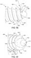
- FIG. 1Gis a perspective view of the distal tip of the bone screw of FIG. 1A ;
- FIG. 1His another perspective view of the distal tip of the bone screw of FIG. 1A ;
- FIG. 1Iis another perspective view of the distal tip of the bone screw of FIG. 1A ;
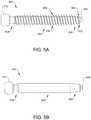
- FIG. 2is a cross-sectional side view of another embodiment of a bone screw
- FIG. 3Ais a side view of another embodiment of a bone screw
- FIG. 3Bis a cross-sectional side view of the bone screw of FIG. 3A ;
- FIG. 3Cis a distal-to-proximal end view of the bone screw of FIG. 3A ;
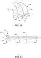
- FIG. 3Dis a perspective view of a cross-sectional portion of the distal tip of the bone screw of FIG. 3A ;
- FIG. 3Eis another perspective view of the cross-sectional portion of the distal tip of the bone screw of FIG. 3D ;
- FIG. 4is a cross-sectional side view of a distal tip of another embodiment of a bone screw
- FIG. 5Ais a side view of another embodiment of a bone screw
- FIG. 5Bis a side view of the shank of the bone screw of FIG. 5A , with the threads removed;
- FIG. 5Cis a cross-sectional side view of the bone screw of FIG. 5A ;
- FIG. 5Dis a distal-to-proximal end view of the bone screw of FIG. 5A ;
- FIG. 5Eis a perspective view of the distal tip of the bone screw of FIG. 5A ;
- FIG. 5Fis another perspective view of the distal tip of the bone screw of FIG. 5A ;
- FIG. 5Gis another perspective view of the distal tip of the bone screw of FIG. 5A ;
- FIG. 6is a perspective view of the bone screw of FIG. 1 shown with a receiver member and a compression cap to form a bone screw assembly.
- various screwsare provided herein that are configured to be implanted in bone, such as in the cervical spine, that can be advanced at a variety of angles with or without a guide hole in the bone. While the bone screws are described in connection with spinal operations and particularly placement in the cervical spine, the screws can be used in connection with any type of bone, tissue (such as in a suture anchor or for lagging soft tissue to bone such as in a shoulder), or in other non-surgical applications.
- a bone screwis provided with an elongate shank having a distal end or tip that is configured to cut bone as the bone screw is threaded into bone.
- the screwcan have at least two threads extending along the elongate shank.
- the distal tip portion of the bone screwcan have a distal facing surface, and each of the threads and the distal facing surface can define cutting edges that are positioned radially outward from a central longitudinal axis of the elongate shank.
- the cutting edgescan be distal of at least a portion of the distal facing surface to allow the cutting edges to contact bone upon placement of the screw against bone at a variety of angles relative to the surface of bone. As a result, when the screw is rotated, the cutting edges can be configured to engage and cut into bone, allowing the screw to create its own path into bone.
- FIGS. 1A-1Iillustrate one embodiment of a bone screw 100 with an elongate shank 102 having a proximal end 104 , a distal end 106 , and a central longitudinal axis L 1 .
- the screw 100can include a head 112 at the proximal end having a drive feature 114 configured to couple with a driver tool (not shown) for advancing the screw 100 into bone.
- the screwcan also have two or more threads formed therealong that terminate at a distal tip on the distal end 106 that is configured to cut bone.
- the head 112 of the bone screw 100can have various configurations, and various drive features can be formed in or on the head.
- the drive feature 114can be configured to receive a driver tool, such as a screw driver, a hexagonal driver, etc. Any complementary mating features can be used, however.
- the headcan be shaped to be received in a drive socket of a driver tool, or alternatively the bone screw can be headless, and the shank can mate with a driver tool (not shown).
- the elongate shank 102 of the bone screw 100can also have various configurations.
- the elongate shank 102is shown in FIG. 1B with the threads removed.
- the illustrated shank 102has a cylindrical body with a constant diameter extending along a majority thereof, representing a minor diameter of the bone screw 100 .
- the shankcan be tapered distally, for example at the distal end, transitioning from a larger diameter to a smaller distal-most diameter.
- the diametercan be constant along approximately 70 to 85% of the total length of the shank 102 , with the tapered distal end being 15 to 30%.
- the shank 102can taper along the entire length with a larger diameter at a proximal end of the shank tapering to a smaller diameter at a distal end thereof. Accordingly, tapering of the shank can be continuous along the length of the shank such that the diameter decreases at a constant rate along the length thereof, or tapering can be located just at a distal end thereof such that only a distal portion of the shank is tapered while a proximal portion has a constant diameter.
- the elongate shankcan include threads formed therealong.
- the screw 100has two threads 130 formed on an external surface thereof, but two or more threads can be used, for example two, three, four, or five threads.
- the threads 130start on opposite sides (e.g., 180 degrees apart) of the shank 102 so that they are opposed to each other and extend in a rotating pattern along at least part of the elongate shank 102 between the proximal end 104 and the distal end 106 to form a helix.
- the threadsare preferably positioned equidistant from each other around the shank 102 such that the thread starts are balanced with each other.
- the threads 130can each have a distal-most end that terminates at or near a cutting edge 122 , as discussed in further detail below.
- the threads 130can have an approximately constant thread pitch as well as a constant lead along the entire length of the shank 102 .
- each of the threads 130has a proximal surface 132 that faces proximally, a distal surface 134 that faces distally, and an outer-most radial surface 136 that can extend at an angle between and relative to the proximal and distal facing surfaces 132 , 134 .
- a thread profile of each of the threads 130can be, for example, square or rectangular in shape. In other embodiments, the thread profile of the threads can be triangular with no radial surface, rounded, etc., and a height and a width of each of the threads can vary.
- the threadsare not symmetrical, such that the proximal surface 132 extends to the outer-most radial surface 136 at a steeper angle relative to a plane perpendicular to the longitudinal axis L 1 as compared to the distal surface 134 , as seen in FIGS. 1D and 1E .
- symmetrical threadscan be used in various embodiments.
- the threads discussed hereincan be selected to facilitate engagement with bone. Additionally, the diameters of the threads can vary similar to the diameter of the elongate shank discussed above, wherein diameters of the thread(s) represent major diameters of the bone screws. As discussed above with the diameter of the elongate shank representing a minor diameter, the major and minor diameters of a bone screw can taper from one end to the other of a bone screw, such as from a proximal end to a distal end. The major and minor diameter taper can be the same or different.
- the start of the major and minor diameter tapercan be at the same location along an elongate shank of a bone screw or can be different, resulting in constant crest width or varying crest width.
- the major diametercan represent the largest diameter of a screw thread
- the minor diametercan represent the smallest diameter of a screw thread. While threads are shown herein, other surface features can be used in other embodiments.
- bone screwscan be configured to permit the screw to rotate in one direction but resist or prevent rotation in the opposite direction and/or can include cleats, spikes, friction-fit features, etc., formed thereon.
- the screw 100can also have a variety of different distal tip configurations.
- the distal end 106 of the bone screw 100can have a distal facing surface 115 that forms the distal-most surface of the bone screw 100 .
- the distal facing surface 115can have an outer edge extending therearound and defining a perimeter of the distal facing surface 115 . While the shape of the distal facing surface 115 can vary, in the illustrated embodiment, the distal facing surface 115 is substantially oblong, with concave and convex regions formed along the outer edge defining the perimeter.
- the distal facing surface 115has opposed convex regions 117 that are positioned radially about the central longitudinal axis and that define the majority of the outer perimeter. Smaller opposed concave regions 119 extend along opposed ends of the distal facing surface 115 and are spaced further radially outward of the convex regions 117 .
- the shape of the distal facing surface 115can vary, but in the illustrated embodiment it has a slight tip or point formed at the mid-point thereof, aligned with the central longitudinal axis L 1 . This can result in a slight conical shape of the distal facing surface 115 , for example as illustrated in FIG. 1D , such that when viewed along a cross-section extending through the axis L 1 , the distal end 106 of the screw 100 can be convex.
- the distal facing surface 115 of the screw 100can thus define an acute angle Al with a plane extending perpendicular to the central longitudinal axis L 1 and extending through the mid-point at the distalmost point. In certain exemplary embodiment, the angle Al can be, for example, about 10 degrees. This conical shape can facilitate effective docking of the bone screw 100 in bone while still allowing the cutting edges 122 to directly engage bone.
- the distal end 106can also have the two or more cutting edges 122 formed thereon that are configured to facilitate cutting of bone during rotation of the bone screw 100 into bone.
- the cutting edges 122can be formed along a portion of the outer perimeter of the distal facing surface 115 .
- the cutting edges 122are formed along the concave regions 119 of the perimeter of the distal facing surface 115 , and on opposed sides of the bone screw at a location radially outward of the central longitudinal axis Al.
- the cutting edges 122can be defined by an intersection of the distal facing surface 115 and the proximal surface 132 of each thread 130 .
- each threadcan terminate prior to the cutting edge 122 , as best shown in FIG. 1G .
- the proximal surface 134 and the outer-most radial surface 136 of each threadtaper toward one another at the distal terminal end of the thread, terminating at one end of the cutting edge 122 .
- the distal surface 134 of each thread at the distal end of the bone screwextends between the outer-most radial surface 136 of the thread and the distal facing surface 115 of the bone screw.
- each cutting edge 122can have a concave curved shape, defining a portion of the outer perimeter of the distal facing surface 115 . While curved, the cutting edges 122 can generally extend radially between the longitudinal axis L 1 and the outer diameter of the bone screw 100 . As a result of the shape and position of the cutting edges 122 , the cutting edges 122 are configured to cut bone as the screw is rotated into bone, thereby forming a path for the threads. Effective engagement and cutting can also be achieved even at extreme non-perpendicular angles relative to a bone surface, which are often required in the cervical spine.
- a usercan advance the screw 100 into bone even when the screw 100 is at an oblique or acute angle relative to the surface of bone, such as about 18 to 20 degrees.
- the distal end or tip of the bone screw 100including the cutting edges 122 , can thus be configured to maximize the efficiency of the bone screw 100 and to minimize the torque and downward force required to drive the bone screw 100 into bone.
- FIG. 2illustrates a bone screw 200 similar to bone screw 100 with an elongate shank 202 having a proximal end 204 , a distal end 206 , and a longitudinal axis L 2 .
- the illustrated screw 200also includes a head 212 having a drive feature 214 configured to couple with a driver tool (not shown) for advancing the screw 200 into bone.
- the screwcan have two or more threads 230 formed therealong that terminate at a distal tip on the distal end 106 with leading cutting edges that are configured to cut bone.
- An inner lumen 208is shown extending entirely therethrough along the axis L 2 , and the inner lumen 208 can be configured to receive a guidewire for facilitating placement of the bone screw in bone and/or bone cement to assist in anchoring the bone screw.
- a bone screw 300similar to bone screw 100 , can have an elongate shank 302 having a proximal end 304 and a distal end 306 .
- the screw 300can include a head 312 with a drive feature 314 configured to couple with a driver tool (not shown) for advancing the screw 300 into bone.
- the screwcan have two or more threads 330 formed therealong.
- Each of the threads 330can have a proximal surface 332 that faces proximally, a distal surface 334 that faces distally, and an outer-most radial surface 336 that can extend between and at an angle to the proximal and distal facing surfaces 332 , 334 .
- the threads 330can terminate at a distal tip on the distal end 306 with leading cutting edges 322 that are configured to cut bone, similar to the cutting edges 122 discussed above.
- the distal facing surface 315is concave, with the mid-portion being positioned more proximal than the outer edges of the distal facing surface 315 .
- the distal end 306 of the screw 300can have a bowl shape such that the bone screw is configured to allow direct and unobstructed contact between the cutting edges 322 and bone when the screw 300 is advanced into bone.
- the cutting edges 322are more distal then the mid-portion of the distal facing surface 315 .
- the distal facing surface 315can thus have sidewalls that extend at an acute angle relative to a plane extending perpendicular to the longitudinal axis L 3 . In certain exemplary embodiments, the angle can be about ⁇ 10 degrees.
- the cutting edges 322can be formed along an outer perimeter of the distal facing surface 315 on opposed sides thereof. Each cutting edges 322 can be defined by an intersection between the distal facing surface 315 and the proximal surface 332 of each of the threads 330 , similar to cutting edges 122 .
- the cutting edges 322can extend radially outward between a longitudinal axis L 3 of the bone screw 300 and an outer diameter of the bone screw 300 .
- Each cutting edge 322can also have a curved concave shape.
- the outer perimeter of the distal facing surface 315can also include convex regions, similar to those discussed above with respect to surface 115 .
- the cutting edges 322protrude distally into even greater engagement with bone, without any point of contact on the distal end 306 of the screw 300 until the cutting edges 322 engage bone.
- the cutting edges 322can thus effectively cut bone from a variety of different angles, allowing a user to place the screw 300 into bone in numerous different operational situations while allowing the screw 300 to create its own path into bone. For example, a user can advance the screw 300 into bone even when the screw 300 is at an oblique or acute angle relative to the surface of bone, such as about 18 to 20 degrees.
- the cutting edges 322can be configured to maximize the efficiency of the bone screw 300 and to minimize the torque and downward force required to drive the bone screw 300 into bone while also removing any distal protrusion that can accidentally interfere with operation of the cutting edges 322 .
- an inner lumencan be formed in a bone screw with a concave distal end.
- FIG. 4illustrates a bone screw 400 similar to the bone screw 300 with an elongate shank 402 having a proximal end (not shown), a distal end 406 , and a longitudinal axis L 4 .
- the illustrated screw 400includes a head with a drive feature (not shown) configured to couple with a driver tool (not shown) for advancing the screw 400 into bone.
- the screwcan have two or more threads 430 formed therealong that terminate at a distal tip on the distal end 406 with leading cutting edges 422 that are configured to cut bone.
- An inner lumen 408can be formed through the elongate shank 402 along the axis L 4 , and the inner lumen 408 can be configured to receive a guidewire for facilitating placement of the bone screw in bone and/or bone cement to assist in anchoring the bone screw.
- FIGS. 5A-5Gillustrate a bone screw 600 similar to bone screw 100 with an elongate shank 602 having a proximal end 604 and a distal end 606 .
- the screw 600can also include a head 612 with a drive feature 614 configured to couple with a driver tool (not shown) for advancing the screw 600 into bone.
- the screwcan have two or more threads 630 formed therealong.
- Each of the threads 630can have a proximal surface 632 , a distal surface 634 , and an outer-most radial surface 636 that can extend at an angle to the proximal and distal surfaces 632 , 634 .
- the threads 630can terminate at a distal tip on the distal end 606 with cutting edges 622 that are configured to cut bone.
- the distal tip configuration, including the cutting edges 622can have the same configuration as the bone screws discussed above.
- a nub 608extends distally from a central or mid portion of a distal facing surface 615 of the bone screw 600 .
- the nub 608can have a variety of shapes, such as a generally conical shape.
- the nub 608can be cylindrical at a proximal base connecting to the distal facing surface 615 and can taper to a rounded or curved tip at a distal-most end.
- the nub 608can be aligned with the central longitudinal axis and can be configured to fit into a pilot hole punched or drilled into bone to allow a user to quickly and easily line up the screw 600 with the bone, for example using the conical shape to ensure the screw 600 is securely positioned in the pilot hole.
- the diameter of the nub 608is preferably smaller than the minor diameter of the threads 630 of the screw 600 to allow the cutting edges 622 to be formed and to help ensure that the threads 630 are large enough to still engage bone as the screw 600 is advanced into bone.
- the bone screws and shanks disclosed hereincan be part of a bone anchor assembly.
- the bone screw 100can be used with a polyaxial receiver 1000 and a compression cap 1100 .
- the receiver 1000can be in the form of a U-shaped body having screw extension tabs 1002 extending proximally therefrom.
- the receiver 1000can have an inner cavity configured to seat the head 112 of the bone screw 100 .
- the elongate shank 102can extend through an opening in a distal end of the receiver 1000 .
- the compression cap 1100can be configured to be received in the receiver 1000 and positioned proximally from the bone screw 100 .
- a spinal rod(not shown) can be positioned between the screw extension tabs 1002 , and it can be seated in a proximal portion of the compression cap 1100 .
- the assemblycan also include a set screw (not shown) configured to be received between the screw extension tabs 1002 , and it can apply a distal force to the spinal rod and the compression cap 1100 to lock the rod within the receiver 1000 and to lock the bone screw 100 in place relative to the receiver 1000 .
- the outer surfaces of each of the screw extension tabs 1002can include a feature, such as a recess, dimple, notch, projection, or the like, to facilitate connection of the receiver 1000 to instruments.
- the screw extension tabs 1002can include an arcuate groove at the respective free end of the tabs.
- the bone screw 100can be a favored angle screw, for example as disclosed in U.S. Pat. No. 6,974,460, issued on Dec. 13, 2005, and in U.S. Pat. No. 6,736,820, issued on May 18, 2004, both of which are hereby incorporated by reference herein.
- the bone anchor assemblycan be a conventional (non-biased) polyaxial screw in which the bone screw pivots in the same amount in every direction.
- the surgical instruments disclosed hereincan be configured to operate in conjunction with bone anchor assemblies of the type known in the art. Further information on screws can be found in U.S. patent application Ser.
- a kitcan be provided that includes one or more of the screws disclosed herein along with one or more screw assemblies, such as that illustrated in FIG. 8 .
- an exemplary kitcan include a plurality of screws and/or screw assemblies of varying type and size, such that a surgeon can select the appropriate screw and/or screw assembly for a particular application.
- the bone screws 100 , 200 , 300 , 400 , 600can be inserted into a body of a patient, either as part of a screw assembly or as part of another procedure.
- the distal end 106 of the bone screw 100can be placed against bone, such as a vertebral pedicle, e.g., in the cervical spine of a patient.
- a driver tool(not shown) can engage the drive feature 114 , and the driver tool can be rotated to rotate the bone screw 100 , e.g., clockwise, relative to the bone.
- the cutting edges 122rotate, they can cut away bone and cause the screw 100 to advance forward into the bone.
- the threads 130can engage bone, which can secure the bone screw 100 in bone.
- the driver toolcan continue to be rotated until the bone screw 100 is fully driven into the bone.
- a usercan position at least two cutting edges 122 formed along an outer perimeter of the distal facing surface 115 of the bone screw 100 in contact with a bone surface in the cervical spine of a patient.
- the cutting edges 112can engage the bone surface, and the cutting edges 122 can be defined by a portion of the outer perimeter of the distal facing surface 115 and the proximal surface 132 of at least two threads 130 .
- Rotating the bone screw 100can cause the cutting edges 112 to cut away bone to advance the bone screw into bone.
- the bone screw 100can be positioned at an angle other than 90 degrees relative to the bone surface, and a distal protrusion on the distal facing surface 115 can be inserted into a guide hole formed in the bone.
- a central region of the distal facing surface 115can be positioned proximal of the cutting edges 122 such that the central region does not contact the bone surface when the at least two cutting edges are positioned in contact with the bone surface.
- the screws disclosed hereincan be formed from any of a variety of materials.
- the screwscan be formed from non-absorbable materials, such as polysulfone, or metals such as titanium and titanium alloys.
- the screwscan be formed from or can include a coating made of a biocompatible, bioabsorbable material that can reduce immunological problems associated with having a foreign substance within the body over a prolonged period of time.
- Exemplary materials from which the screws disclosed herein can be formedinclude bioabsorbable elastomers, copolymer combinations such as polylactic acid-polyglycolic acid (PLA-PGA), and bioabsorbable polymers such as aliphatic polyesters, poly(amino acids), copoly(ether-esters), polyalkylenes oxalates, polyamides, tyrosine derived polycarbonates, poly(iminocarbonates), polyorthoesters, polyoxaesters, polyamidoesters, polyoxaesters containing amine groups, poly(anhydrides), polyphosphazenes, biomolecules (i.e., biopolymers such as collagen, elastin, bioabsorbable starches, etc.) and blends thereof.
- bioabsorbable elastomerssuch as polylactic acid-polyglycolic acid (PLA-PGA), and bioabsorbable polymers such as aliphatic polyesters, poly(amino
- the screwscan be formed from polylactic acid, or a composite blend of tricalcium phosphate and polylactic acid.
- One or more coatingscan be used on the bone screws, for example coatings to promote bone growth or improve bone adherence to the bone screw.
- the screws disclosed hereincan be formed from a single, unitary material and structure or can be formed from one or more materials listed above.
- the screws disclosed hereincan be provided in any of a variety of sizes, depending on patient anatomy, procedure type, screw assembly size, and various other parameters which will be readily apparent to one having ordinary skill in the art.
- the screws disclosed hereincan have a variety of lengths, for example, about 30 mm to 60 mm or about 80 mm to 100 mm, and can have a variety of diameters, such as about 3.0 mm, 3.5 mm, 4.0 mm, 4.5 mm, 5 mm, or 5.5 mm.
Landscapes
- Health & Medical Sciences (AREA)
- Orthopedic Medicine & Surgery (AREA)
- Life Sciences & Earth Sciences (AREA)
- Surgery (AREA)
- Neurology (AREA)
- Heart & Thoracic Surgery (AREA)
- Engineering & Computer Science (AREA)
- Biomedical Technology (AREA)
- Nuclear Medicine, Radiotherapy & Molecular Imaging (AREA)
- Medical Informatics (AREA)
- Molecular Biology (AREA)
- Animal Behavior & Ethology (AREA)
- General Health & Medical Sciences (AREA)
- Public Health (AREA)
- Veterinary Medicine (AREA)
- Surgical Instruments (AREA)
Abstract
Description
Claims (14)
Priority Applications (9)
| Application Number | Priority Date | Filing Date | Title |
|---|---|---|---|
| US15/852,310US10772667B2 (en) | 2017-12-22 | 2017-12-22 | Bone screw with cutting tip |
| EP24222117.4AEP4523649A3 (en) | 2017-12-22 | 2018-12-17 | Bone screw with cutting tip |
| CN201880083078.0ACN111526829B (en) | 2017-12-22 | 2018-12-17 | Bone screw with cutting tip |
| PCT/US2018/065966WO2019126019A1 (en) | 2017-12-22 | 2018-12-17 | Bone screw with cutting tip |
| EP18840114.5AEP3727176B1 (en) | 2017-12-22 | 2018-12-17 | Bone screw with cutting tip |
| JP2020533206AJP7430638B2 (en) | 2017-12-22 | 2018-12-17 | Bone screw with cutting tip |
| AU2018389599AAU2018389599B2 (en) | 2017-12-22 | 2018-12-17 | Bone screw with cutting tip |
| US16/991,109US11751925B2 (en) | 2017-12-22 | 2020-08-12 | Bone screw with cutting tip |
| US18/238,075US20230397940A1 (en) | 2017-12-22 | 2023-08-25 | Bone screw with cutting tip |
Applications Claiming Priority (1)
| Application Number | Priority Date | Filing Date | Title |
|---|---|---|---|
| US15/852,310US10772667B2 (en) | 2017-12-22 | 2017-12-22 | Bone screw with cutting tip |
Related Child Applications (1)
| Application Number | Title | Priority Date | Filing Date |
|---|---|---|---|
| US16/991,109ContinuationUS11751925B2 (en) | 2017-12-22 | 2020-08-12 | Bone screw with cutting tip |
Publications (2)
| Publication Number | Publication Date |
|---|---|
| US20190192203A1 US20190192203A1 (en) | 2019-06-27 |
| US10772667B2true US10772667B2 (en) | 2020-09-15 |
Family
ID=65237138
Family Applications (3)
| Application Number | Title | Priority Date | Filing Date |
|---|---|---|---|
| US15/852,310Active2038-03-24US10772667B2 (en) | 2017-12-22 | 2017-12-22 | Bone screw with cutting tip |
| US16/991,109Active2038-07-29US11751925B2 (en) | 2017-12-22 | 2020-08-12 | Bone screw with cutting tip |
| US18/238,075PendingUS20230397940A1 (en) | 2017-12-22 | 2023-08-25 | Bone screw with cutting tip |
Family Applications After (2)
| Application Number | Title | Priority Date | Filing Date |
|---|---|---|---|
| US16/991,109Active2038-07-29US11751925B2 (en) | 2017-12-22 | 2020-08-12 | Bone screw with cutting tip |
| US18/238,075PendingUS20230397940A1 (en) | 2017-12-22 | 2023-08-25 | Bone screw with cutting tip |
Country Status (6)
| Country | Link |
|---|---|
| US (3) | US10772667B2 (en) |
| EP (2) | EP4523649A3 (en) |
| JP (1) | JP7430638B2 (en) |
| CN (1) | CN111526829B (en) |
| AU (1) | AU2018389599B2 (en) |
| WO (1) | WO2019126019A1 (en) |
Cited By (3)
| Publication number | Priority date | Publication date | Assignee | Title |
|---|---|---|---|---|
| US11376050B2 (en) | 2017-06-27 | 2022-07-05 | Medos International Sarl | Bone screw |
| US20230240728A1 (en)* | 2015-10-27 | 2023-08-03 | Ctl Medical Corporation | Modular rod reduction tower and related methods |
| US11751925B2 (en) | 2017-12-22 | 2023-09-12 | Medos International Sarl | Bone screw with cutting tip |
Families Citing this family (3)
| Publication number | Priority date | Publication date | Assignee | Title |
|---|---|---|---|---|
| US11284928B2 (en) | 2018-12-17 | 2022-03-29 | Warsaw Orthopedic, Inc. | Surgical implant and method of use |
| WO2023039398A1 (en)* | 2021-09-07 | 2023-03-16 | Integrity Implants Inc. | Ball-nosed pedicle screw |
| CN218106136U (en)* | 2022-04-18 | 2022-12-23 | 北京聚科动物骨科器械有限公司 | Animal spine fixing device |
Citations (61)
| Publication number | Priority date | Publication date | Assignee | Title |
|---|---|---|---|---|
| US5300076A (en) | 1991-10-11 | 1994-04-05 | Societe De Fabrication De Materiel Orthopedique-Sofamore | Percutaneous bone screw for supporting a stereotaxy frame |
| US5364400A (en)* | 1992-02-14 | 1994-11-15 | American Cyanamid Co. | Interference implant |
| US5443509A (en)* | 1992-12-10 | 1995-08-22 | Linvatec Corporation | Interference bone-fixation screw with multiple interleaved threads |
| US5593410A (en) | 1989-10-26 | 1997-01-14 | Vrespa; Giuseppe | Screw device for fixing prostheses to bones |
| US5733307A (en) | 1996-09-17 | 1998-03-31 | Amei Technologies, Inc. | Bone anchor having a suture trough |
| US5928236A (en) | 1994-07-04 | 1999-07-27 | Depuy France | Locking pin or screw device for an osteosynthesis plate or for the coaptation of bone fragments |
| US5968078A (en) | 1995-08-25 | 1999-10-19 | Ultraortho, Inc. | Stabilizer for human joints |
| US6306140B1 (en) | 2001-01-17 | 2001-10-23 | Synthes (Usa) | Bone screw |
| US6398785B2 (en) | 1998-04-14 | 2002-06-04 | Joseph Edward Carchidi | Apparatus for rigidly fixing craniomaxillofacial tissue grafts and bone plates |
| US6517542B1 (en) | 1999-08-04 | 2003-02-11 | The Cleveland Clinic Foundation | Bone anchoring system |
| US20030069582A1 (en) | 2001-03-30 | 2003-04-10 | Culbert Brad S. | Method and apparatus for bone fixation with secondary compression |
| US20040044345A1 (en) | 2002-08-28 | 2004-03-04 | Demoss Richard Marshal | Shallow penetration bone screw |
| US6736820B2 (en) | 2000-11-10 | 2004-05-18 | Biedermann Motech Gmbh | Bone screw |
| US6743233B1 (en) | 2000-08-02 | 2004-06-01 | Orthopaedic Biosystems, Ltd., Inc. | Medical screw and method of installation |
| US20040106925A1 (en)* | 2002-11-25 | 2004-06-03 | Culbert Brad S. | Soft tissue anchor and method of using same |
| US6755835B2 (en) | 1999-08-14 | 2004-06-29 | Aesculap Ag & Co. Kg | Bone screw |
| US20050021036A1 (en) | 2003-07-21 | 2005-01-27 | Whitmore Robin C. | Self-drilling, self-tapping bone screw |
| US20050101961A1 (en) | 2003-11-12 | 2005-05-12 | Huebner Randall J. | Bone screws |
| US6974460B2 (en) | 2001-09-14 | 2005-12-13 | Stryker Spine | Biased angulation bone fixation assembly |
| US7008227B2 (en) | 2002-03-04 | 2006-03-07 | Carmichael Robert P | Self-drilling implant |
| US20060100627A1 (en)* | 2004-11-09 | 2006-05-11 | Arthrotek, Inc. | Tissue fixation device |
| US20060217727A1 (en)* | 2002-06-21 | 2006-09-28 | Chad Munro | Bone screw |
| US7179261B2 (en) | 2003-12-16 | 2007-02-20 | Depuy Spine, Inc. | Percutaneous access devices and bone anchor assemblies |
| US7198488B2 (en) | 2002-07-26 | 2007-04-03 | Bredent Dentalgerate Fach- Und Organisationsberatung Peter Brehm | Dental implant comprising an anchoring head and a screw element |
| US20070162029A1 (en) | 2003-07-21 | 2007-07-12 | Whitmore Robin C | Self-drilling self-tapping bone screw |
| US20070162028A1 (en) | 2005-12-09 | 2007-07-12 | Jesse Jackson | Cannulated screw |
| FR2932975A1 (en) | 2008-06-26 | 2010-01-01 | Fournitures Hospitalieres Ind | Percutaneous osteosynthesis screw for e.g. hand bone, during orthopedic surgery, has screw body comprising grooves extending on external surface of body and forming knife-edged ridge with filet of external thread to perform tapping in bone |
| US20100114174A1 (en) | 2008-10-30 | 2010-05-06 | Bryan Jones | Systems and Methods for Delivering Bone Cement to a Bone Anchor |
| US20100211118A1 (en) | 2009-02-16 | 2010-08-19 | Stryker Trauma Ag | Bone screw and method of manufacturing same |
| US7819905B2 (en) | 2004-12-17 | 2010-10-26 | Zimmer Spine, Inc. | Self drilling bone screw |
| US20110070558A1 (en)* | 2008-05-19 | 2011-03-24 | Osstemimplant Co., Ltd. | Dental implant fixture |
| US8029285B2 (en) | 2001-08-15 | 2011-10-04 | Astra Tech Ab | Implant, arrangement comprising an implant, and method for inserting said implant in bone tissue |
| US20110288599A1 (en) | 2010-05-19 | 2011-11-24 | Michael Michielli | Bone Anchors |
| US20110295319A1 (en) | 2008-08-15 | 2011-12-01 | Kinetic Spine Technologies Inc. | Dynamic pedicle screw |
| US20120203290A1 (en) | 2011-02-04 | 2012-08-09 | Interventional Spine, Inc. | Method and apparatus for spinal fixation |
| FR2971413A1 (en) | 2011-02-15 | 2012-08-17 | Jean-Pierre Py | Cannulated self-tapping screw for osteosynthesis of e.g. hand bone, has threaded distal portion including thread whose proximal edge is inclined toward proximal side of screw and whose outer edge forms sharp edge with distal edge of thread |
| US8333590B2 (en) | 1998-07-17 | 2012-12-18 | Astra Tech Ab | Implant having circumferentially oriented roughness |
| US20130053901A1 (en) | 2011-08-25 | 2013-02-28 | Philip Cormier | Bone anchors |
| US8414628B2 (en) | 2006-10-26 | 2013-04-09 | Warsaw Orthopedic, Inc. | Bone screw |
| US20130096618A1 (en) | 2011-10-14 | 2013-04-18 | Thibault Chandanson | Bone anchor assemblies |
| US20140058460A1 (en) | 2012-08-24 | 2014-02-27 | Gary Jack Reed | Orthopedic fastener device |
| US20140081339A1 (en)* | 2010-03-10 | 2014-03-20 | Smith & Nephew, Inc. | Anchor having a controlled driver orientation |
| US20140114312A1 (en) | 2010-02-24 | 2014-04-24 | William R. Krause | Flexible Intramedullary Nail |
| FR3000664A3 (en) | 2013-01-04 | 2014-07-11 | Small Bone Innovations Internat | Screw for treatment of small bone in e.g. hand, has machining screed flush-mounted at sector of proximal turn of thread, and proximal and distal threaded portions arranged on coil for forming step edge in unscrewing direction of screw |
| FR3000662A3 (en) | 2013-01-04 | 2014-07-11 | Small Bone Innovations Internat | Self-drilling and self-tapping bone screw for treatment of e.g. cortical bone, has notch extending from distal edge of screw, along base of cutting face of each tooth, where notch is arranged parallel to axis of screw |
| US20140234800A1 (en) | 2010-08-18 | 2014-08-21 | Cortex Dental Implants Industries, Ltd. | Anchoring element and method |
| US20140257409A1 (en) | 2013-03-06 | 2014-09-11 | Gary Jack Reed | Bone screw |
| US20140277188A1 (en)* | 2013-03-15 | 2014-09-18 | Nicholas Poulos | Self drilling, self-tapping bone screw and method of installing for bicortical purchase |
| US20140303676A1 (en)* | 2013-04-09 | 2014-10-09 | John D. Stroncek | Open-architecture interference screw |
| US8945190B2 (en) | 2002-07-19 | 2015-02-03 | Interventional Spine, Inc. | Method and apparatus for spinal fixation |
| US20150044639A1 (en) | 1997-11-11 | 2015-02-12 | Nobel Biocare Services Ag | Arrangement for Obtaining Reliable Anchoring of a Threaded Implant in a Bone |
| WO2015091916A1 (en) | 2013-12-19 | 2015-06-25 | Rita Leibinger GmbH & Co. KG | Self-tapping, tension absorbing bone screw |
| US9079263B2 (en) | 2012-08-24 | 2015-07-14 | RTG Scientific, Inc. | Orthopedic fastener method |
| US20150196388A1 (en)* | 2010-03-10 | 2015-07-16 | Smith & Nephew, Inc. | Composite Interference Screws and Drivers |
| US20150230844A1 (en)* | 2012-10-09 | 2015-08-20 | LLM IP Holdings Pty Ltd. | Screw |
| FR3021206A1 (en) | 2014-05-22 | 2015-11-27 | Euros Sa | OSTEOSYNTHESIS SCREW FOR SOLIDARIZING BONE FRAGMENTS |
| US20160081771A1 (en) | 2003-05-21 | 2016-03-24 | Nobel Biocare Services Ag | Condensing skeletal implant that facilitate insertions |
| US20160113693A1 (en) | 2006-02-16 | 2016-04-28 | Warsaw Orthopedic, Inc. | Multi-thread bone screw and method |
| US9358057B1 (en) | 2015-02-25 | 2016-06-07 | Amendia, Inc. | Sacroiliac screw |
| US9848962B2 (en)* | 2010-01-14 | 2017-12-26 | Osstemimplant Co., Ltd. | Drill for implant surgery |
| US20190223917A1 (en)* | 2016-09-16 | 2019-07-25 | Wayne Gray | Bone anchor, instruments, and methods for use |
Family Cites Families (28)
| Publication number | Priority date | Publication date | Assignee | Title |
|---|---|---|---|---|
| DE4138555A1 (en)* | 1991-11-23 | 1993-05-27 | Hilti Ag | SET SCREW FOR SELF-TAPING |
| US5871486A (en)* | 1993-01-21 | 1999-02-16 | Acumed, Inc. | Variable pitch bone screw |
| US6685728B2 (en)* | 2002-01-25 | 2004-02-03 | Stryker Endoscopy | Threaded suture anchor and method of use |
| DE10350424B4 (en)* | 2003-10-29 | 2006-03-30 | Ulrich Gmbh & Co. Kg | bone screw |
| WO2005058175A1 (en)* | 2003-12-19 | 2005-06-30 | Depuy International Limited | A bone screw |
| US8034090B2 (en)* | 2004-11-09 | 2011-10-11 | Biomet Sports Medicine, Llc | Tissue fixation device |
| HRP20050295B1 (en) | 2005-03-29 | 2010-11-30 | Roth Sandor | The canulated titanium implant for correcting flat feet in children |
| US8133261B2 (en)* | 2007-02-26 | 2012-03-13 | Depuy Spine, Inc. | Intra-facet fixation device and method of use |
| WO2009099963A2 (en)* | 2008-01-31 | 2009-08-13 | Cayenne Medical, Inc | Self-tapping biocompatible interference bone screw |
| US8394132B2 (en) | 2008-09-16 | 2013-03-12 | Orthohelix Surgical Designs, Inc. | Orthopedic compression screw |
| AU2009333625B2 (en)* | 2008-12-09 | 2015-09-03 | Smith & Nephew, Inc. | Tissue repair assembly |
| WO2011057079A1 (en)* | 2009-11-05 | 2011-05-12 | K2M, Inc. | Semi-constrained bone screw |
| EP2364657B1 (en)* | 2010-03-08 | 2012-05-09 | Stryker Trauma SA | Bone fixation system with curved profile threads |
| FR2971138B1 (en) | 2011-02-09 | 2013-09-20 | Orthopaedic & Spine Dev | OSTEOSYNTHESIS PROSTHESIS FOR THE REDUCTION OF NON-DISPLACED FRACTURES |
| US20120232599A1 (en) | 2011-03-10 | 2012-09-13 | Jared Schoenly | Awl screw fixation members and related systems |
| US8740531B2 (en)* | 2011-08-31 | 2014-06-03 | Taiwan Shan Yin Int'l Co., Ltd. | Screw |
| US20130226239A1 (en)* | 2012-02-23 | 2013-08-29 | Moti Altarac | Facet screw and method for spinal stabilization |
| US20130253595A1 (en)* | 2012-03-26 | 2013-09-26 | Spartek Medical, Inc. | System and method for securing an implant to a bone containing bone cement |
| JP5607114B2 (en)* | 2012-06-26 | 2014-10-15 | 株式会社トープラ | Tapping screw |
| US20140058461A1 (en) | 2012-08-27 | 2014-02-27 | Michael Black | Fenestrated Bone Screw |
| EP3209220B1 (en) | 2014-10-21 | 2019-09-25 | Roger P. Jackson | Snap-on multi-planar and mono-planar receiver assemblies having integral and multi-part multipurpose positioners for pivoting and non-pivoting retainers |
| BR112017009310B1 (en)* | 2014-11-04 | 2022-10-11 | Depuy Synthes Products, Inc | BONE SCREW WITH BLONDE TIP |
| GB201600263D0 (en)* | 2016-01-07 | 2016-02-24 | Innovate Orthopaedics Ltd | Fixation device and method of manufacture and use |
| US10285745B2 (en)* | 2016-07-05 | 2019-05-14 | Zavation Medical Products Llc | Orthopedic screws |
| CN106618712B (en)* | 2016-12-29 | 2019-03-15 | 大博医疗科技股份有限公司 | A kind of elasticity bone screws |
| US11376050B2 (en) | 2017-06-27 | 2022-07-05 | Medos International Sarl | Bone screw |
| US10772667B2 (en) | 2017-12-22 | 2020-09-15 | Medos International Sarl | Bone screw with cutting tip |
| US11751915B2 (en)* | 2021-07-09 | 2023-09-12 | Roger P. Jackson | Modular spinal fixation system with bottom-loaded universal shank heads |
- 2017
- 2017-12-22USUS15/852,310patent/US10772667B2/enactiveActive
- 2018
- 2018-12-17WOPCT/US2018/065966patent/WO2019126019A1/ennot_activeCeased
- 2018-12-17EPEP24222117.4Apatent/EP4523649A3/enactivePending
- 2018-12-17CNCN201880083078.0Apatent/CN111526829B/enactiveActive
- 2018-12-17AUAU2018389599Apatent/AU2018389599B2/enactiveActive
- 2018-12-17JPJP2020533206Apatent/JP7430638B2/enactiveActive
- 2018-12-17EPEP18840114.5Apatent/EP3727176B1/enactiveActive
- 2020
- 2020-08-12USUS16/991,109patent/US11751925B2/enactiveActive
- 2023
- 2023-08-25USUS18/238,075patent/US20230397940A1/enactivePending
Patent Citations (63)
| Publication number | Priority date | Publication date | Assignee | Title |
|---|---|---|---|---|
| US5593410A (en) | 1989-10-26 | 1997-01-14 | Vrespa; Giuseppe | Screw device for fixing prostheses to bones |
| US5300076A (en) | 1991-10-11 | 1994-04-05 | Societe De Fabrication De Materiel Orthopedique-Sofamore | Percutaneous bone screw for supporting a stereotaxy frame |
| US5364400A (en)* | 1992-02-14 | 1994-11-15 | American Cyanamid Co. | Interference implant |
| US5443509A (en)* | 1992-12-10 | 1995-08-22 | Linvatec Corporation | Interference bone-fixation screw with multiple interleaved threads |
| US5928236A (en) | 1994-07-04 | 1999-07-27 | Depuy France | Locking pin or screw device for an osteosynthesis plate or for the coaptation of bone fragments |
| US5968078A (en) | 1995-08-25 | 1999-10-19 | Ultraortho, Inc. | Stabilizer for human joints |
| US5733307A (en) | 1996-09-17 | 1998-03-31 | Amei Technologies, Inc. | Bone anchor having a suture trough |
| US20150044639A1 (en) | 1997-11-11 | 2015-02-12 | Nobel Biocare Services Ag | Arrangement for Obtaining Reliable Anchoring of a Threaded Implant in a Bone |
| US6398785B2 (en) | 1998-04-14 | 2002-06-04 | Joseph Edward Carchidi | Apparatus for rigidly fixing craniomaxillofacial tissue grafts and bone plates |
| US8333590B2 (en) | 1998-07-17 | 2012-12-18 | Astra Tech Ab | Implant having circumferentially oriented roughness |
| US6517542B1 (en) | 1999-08-04 | 2003-02-11 | The Cleveland Clinic Foundation | Bone anchoring system |
| US6755835B2 (en) | 1999-08-14 | 2004-06-29 | Aesculap Ag & Co. Kg | Bone screw |
| US6743233B1 (en) | 2000-08-02 | 2004-06-01 | Orthopaedic Biosystems, Ltd., Inc. | Medical screw and method of installation |
| US6736820B2 (en) | 2000-11-10 | 2004-05-18 | Biedermann Motech Gmbh | Bone screw |
| US6306140B1 (en) | 2001-01-17 | 2001-10-23 | Synthes (Usa) | Bone screw |
| US20030069582A1 (en) | 2001-03-30 | 2003-04-10 | Culbert Brad S. | Method and apparatus for bone fixation with secondary compression |
| US8029285B2 (en) | 2001-08-15 | 2011-10-04 | Astra Tech Ab | Implant, arrangement comprising an implant, and method for inserting said implant in bone tissue |
| US6974460B2 (en) | 2001-09-14 | 2005-12-13 | Stryker Spine | Biased angulation bone fixation assembly |
| US7008227B2 (en) | 2002-03-04 | 2006-03-07 | Carmichael Robert P | Self-drilling implant |
| US20060217727A1 (en)* | 2002-06-21 | 2006-09-28 | Chad Munro | Bone screw |
| US8945190B2 (en) | 2002-07-19 | 2015-02-03 | Interventional Spine, Inc. | Method and apparatus for spinal fixation |
| US7198488B2 (en) | 2002-07-26 | 2007-04-03 | Bredent Dentalgerate Fach- Und Organisationsberatung Peter Brehm | Dental implant comprising an anchoring head and a screw element |
| US20040044345A1 (en) | 2002-08-28 | 2004-03-04 | Demoss Richard Marshal | Shallow penetration bone screw |
| US20040106925A1 (en)* | 2002-11-25 | 2004-06-03 | Culbert Brad S. | Soft tissue anchor and method of using same |
| US20160081771A1 (en) | 2003-05-21 | 2016-03-24 | Nobel Biocare Services Ag | Condensing skeletal implant that facilitate insertions |
| US20070162029A1 (en) | 2003-07-21 | 2007-07-12 | Whitmore Robin C | Self-drilling self-tapping bone screw |
| US9168077B2 (en) | 2003-07-21 | 2015-10-27 | Surgical Screw Concepts, LLC. | Self-drilling self-tapping bone screw |
| US20050021036A1 (en) | 2003-07-21 | 2005-01-27 | Whitmore Robin C. | Self-drilling, self-tapping bone screw |
| US20050101961A1 (en) | 2003-11-12 | 2005-05-12 | Huebner Randall J. | Bone screws |
| US7179261B2 (en) | 2003-12-16 | 2007-02-20 | Depuy Spine, Inc. | Percutaneous access devices and bone anchor assemblies |
| US20060100627A1 (en)* | 2004-11-09 | 2006-05-11 | Arthrotek, Inc. | Tissue fixation device |
| US7819905B2 (en) | 2004-12-17 | 2010-10-26 | Zimmer Spine, Inc. | Self drilling bone screw |
| US20070162028A1 (en) | 2005-12-09 | 2007-07-12 | Jesse Jackson | Cannulated screw |
| US20160113693A1 (en) | 2006-02-16 | 2016-04-28 | Warsaw Orthopedic, Inc. | Multi-thread bone screw and method |
| US8414628B2 (en) | 2006-10-26 | 2013-04-09 | Warsaw Orthopedic, Inc. | Bone screw |
| US20110070558A1 (en)* | 2008-05-19 | 2011-03-24 | Osstemimplant Co., Ltd. | Dental implant fixture |
| FR2932975A1 (en) | 2008-06-26 | 2010-01-01 | Fournitures Hospitalieres Ind | Percutaneous osteosynthesis screw for e.g. hand bone, during orthopedic surgery, has screw body comprising grooves extending on external surface of body and forming knife-edged ridge with filet of external thread to perform tapping in bone |
| US20110295319A1 (en) | 2008-08-15 | 2011-12-01 | Kinetic Spine Technologies Inc. | Dynamic pedicle screw |
| US20100114174A1 (en) | 2008-10-30 | 2010-05-06 | Bryan Jones | Systems and Methods for Delivering Bone Cement to a Bone Anchor |
| US20100211118A1 (en) | 2009-02-16 | 2010-08-19 | Stryker Trauma Ag | Bone screw and method of manufacturing same |
| US9848962B2 (en)* | 2010-01-14 | 2017-12-26 | Osstemimplant Co., Ltd. | Drill for implant surgery |
| US20140114312A1 (en) | 2010-02-24 | 2014-04-24 | William R. Krause | Flexible Intramedullary Nail |
| US20150196388A1 (en)* | 2010-03-10 | 2015-07-16 | Smith & Nephew, Inc. | Composite Interference Screws and Drivers |
| US20140081339A1 (en)* | 2010-03-10 | 2014-03-20 | Smith & Nephew, Inc. | Anchor having a controlled driver orientation |
| US20110288599A1 (en) | 2010-05-19 | 2011-11-24 | Michael Michielli | Bone Anchors |
| US20140234800A1 (en) | 2010-08-18 | 2014-08-21 | Cortex Dental Implants Industries, Ltd. | Anchoring element and method |
| US20120203290A1 (en) | 2011-02-04 | 2012-08-09 | Interventional Spine, Inc. | Method and apparatus for spinal fixation |
| FR2971413A1 (en) | 2011-02-15 | 2012-08-17 | Jean-Pierre Py | Cannulated self-tapping screw for osteosynthesis of e.g. hand bone, has threaded distal portion including thread whose proximal edge is inclined toward proximal side of screw and whose outer edge forms sharp edge with distal edge of thread |
| US20130053901A1 (en) | 2011-08-25 | 2013-02-28 | Philip Cormier | Bone anchors |
| US20130096618A1 (en) | 2011-10-14 | 2013-04-18 | Thibault Chandanson | Bone anchor assemblies |
| US20140058460A1 (en) | 2012-08-24 | 2014-02-27 | Gary Jack Reed | Orthopedic fastener device |
| US9079263B2 (en) | 2012-08-24 | 2015-07-14 | RTG Scientific, Inc. | Orthopedic fastener method |
| US20150230844A1 (en)* | 2012-10-09 | 2015-08-20 | LLM IP Holdings Pty Ltd. | Screw |
| US10092341B2 (en)* | 2012-10-09 | 2018-10-09 | Lmm Ip Holdings Pty Ltd | Screw |
| FR3000662A3 (en) | 2013-01-04 | 2014-07-11 | Small Bone Innovations Internat | Self-drilling and self-tapping bone screw for treatment of e.g. cortical bone, has notch extending from distal edge of screw, along base of cutting face of each tooth, where notch is arranged parallel to axis of screw |
| FR3000664A3 (en) | 2013-01-04 | 2014-07-11 | Small Bone Innovations Internat | Screw for treatment of small bone in e.g. hand, has machining screed flush-mounted at sector of proximal turn of thread, and proximal and distal threaded portions arranged on coil for forming step edge in unscrewing direction of screw |
| US20140257409A1 (en) | 2013-03-06 | 2014-09-11 | Gary Jack Reed | Bone screw |
| US20140277188A1 (en)* | 2013-03-15 | 2014-09-18 | Nicholas Poulos | Self drilling, self-tapping bone screw and method of installing for bicortical purchase |
| US20140303676A1 (en)* | 2013-04-09 | 2014-10-09 | John D. Stroncek | Open-architecture interference screw |
| WO2015091916A1 (en) | 2013-12-19 | 2015-06-25 | Rita Leibinger GmbH & Co. KG | Self-tapping, tension absorbing bone screw |
| FR3021206A1 (en) | 2014-05-22 | 2015-11-27 | Euros Sa | OSTEOSYNTHESIS SCREW FOR SOLIDARIZING BONE FRAGMENTS |
| US9358057B1 (en) | 2015-02-25 | 2016-06-07 | Amendia, Inc. | Sacroiliac screw |
| US20190223917A1 (en)* | 2016-09-16 | 2019-07-25 | Wayne Gray | Bone anchor, instruments, and methods for use |
Non-Patent Citations (1)
| Title |
|---|
| "International Search Report and Written Opinion received for PCT Patent International Application No. PCT/US2018/065966", dated Apr. 12, 2019, 20 pages. |
Cited By (3)
| Publication number | Priority date | Publication date | Assignee | Title |
|---|---|---|---|---|
| US20230240728A1 (en)* | 2015-10-27 | 2023-08-03 | Ctl Medical Corporation | Modular rod reduction tower and related methods |
| US11376050B2 (en) | 2017-06-27 | 2022-07-05 | Medos International Sarl | Bone screw |
| US11751925B2 (en) | 2017-12-22 | 2023-09-12 | Medos International Sarl | Bone screw with cutting tip |
Also Published As
| Publication number | Publication date |
|---|---|
| JP7430638B2 (en) | 2024-02-13 |
| US11751925B2 (en) | 2023-09-12 |
| JP2021506432A (en) | 2021-02-22 |
| AU2018389599A1 (en) | 2020-06-11 |
| EP4523649A2 (en) | 2025-03-19 |
| WO2019126019A1 (en) | 2019-06-27 |
| EP4523649A3 (en) | 2025-05-14 |
| CN111526829A (en) | 2020-08-11 |
| EP3727176A1 (en) | 2020-10-28 |
| US20230397940A1 (en) | 2023-12-14 |
| US20190192203A1 (en) | 2019-06-27 |
| US20200367952A1 (en) | 2020-11-26 |
| AU2018389599B2 (en) | 2024-11-14 |
| EP3727176B1 (en) | 2024-12-25 |
| CN111526829B (en) | 2023-09-29 |
Similar Documents
| Publication | Publication Date | Title |
|---|---|---|
| US20220313331A1 (en) | Bone screw | |
| US11751925B2 (en) | Bone screw with cutting tip | |
| US10874296B2 (en) | Retraction devices, systems, and methods for minimally invasive spinal surgery | |
| US10166116B2 (en) | Helical lock spacer, instruments and methods | |
| JP4792176B2 (en) | Bone screw retention system | |
| KR102230353B1 (en) | Femoral neck fracture implant | |
| US7959564B2 (en) | Pedicle seeker and retractor, and methods of use | |
| US10285745B2 (en) | Orthopedic screws | |
| US20120323242A1 (en) | Surgical awl and method of using the same | |
| US11951010B2 (en) | Sacroiliac joint stabilization system | |
| US10517613B2 (en) | Systems, devices, and methods for guiding surgical devices into bone | |
| US20250025310A1 (en) | Joint stabilization system | |
| US20220280214A1 (en) | Bone anchor |
Legal Events
| Date | Code | Title | Description |
|---|---|---|---|
| FEPP | Fee payment procedure | Free format text:ENTITY STATUS SET TO UNDISCOUNTED (ORIGINAL EVENT CODE: BIG.); ENTITY STATUS OF PATENT OWNER: LARGE ENTITY | |
| AS | Assignment | Owner name:DEPUY SYNTHES PRODUCTS, INC., MASSACHUSETTS Free format text:ASSIGNMENT OF ASSIGNORS INTEREST;ASSIGNORS:RAMSAY, CHRIS;PETERSON, JOSEPH;SIGNING DATES FROM 20180906 TO 20180919;REEL/FRAME:047277/0792 Owner name:MEDOS INTERNATIONAL SARL, SWITZERLAND Free format text:ASSIGNMENT OF ASSIGNORS INTEREST;ASSIGNOR:DEPUY SYNTHES PRODUCTS, INC.;REEL/FRAME:047277/0880 Effective date:20181022 | |
| STPP | Information on status: patent application and granting procedure in general | Free format text:NON FINAL ACTION MAILED | |
| STPP | Information on status: patent application and granting procedure in general | Free format text:RESPONSE TO NON-FINAL OFFICE ACTION ENTERED AND FORWARDED TO EXAMINER | |
| STPP | Information on status: patent application and granting procedure in general | Free format text:NON FINAL ACTION MAILED | |
| STPP | Information on status: patent application and granting procedure in general | Free format text:FINAL REJECTION MAILED | |
| STPP | Information on status: patent application and granting procedure in general | Free format text:NOTICE OF ALLOWANCE MAILED -- APPLICATION RECEIVED IN OFFICE OF PUBLICATIONS | |
| STPP | Information on status: patent application and granting procedure in general | Free format text:DOCKETED NEW CASE - READY FOR EXAMINATION | |
| STPP | Information on status: patent application and granting procedure in general | Free format text:NOTICE OF ALLOWANCE MAILED -- APPLICATION RECEIVED IN OFFICE OF PUBLICATIONS | |
| STPP | Information on status: patent application and granting procedure in general | Free format text:NOTICE OF ALLOWANCE MAILED -- APPLICATION RECEIVED IN OFFICE OF PUBLICATIONS | |
| STPP | Information on status: patent application and granting procedure in general | Free format text:PUBLICATIONS -- ISSUE FEE PAYMENT VERIFIED | |
| STCF | Information on status: patent grant | Free format text:PATENTED CASE | |
| MAFP | Maintenance fee payment | Free format text:PAYMENT OF MAINTENANCE FEE, 4TH YEAR, LARGE ENTITY (ORIGINAL EVENT CODE: M1551); ENTITY STATUS OF PATENT OWNER: LARGE ENTITY Year of fee payment:4 |