US10772647B2 - Device and method for removing occlusions in a biological vessel - Google Patents
Device and method for removing occlusions in a biological vesselDownload PDFInfo
- Publication number
- US10772647B2 US10772647B2US15/528,110US201615528110AUS10772647B2US 10772647 B2US10772647 B2US 10772647B2US 201615528110 AUS201615528110 AUS 201615528110AUS 10772647 B2US10772647 B2US 10772647B2
- Authority
- US
- United States
- Prior art keywords
- extensions
- occlusion
- projections
- thrombus
- extension
- Prior art date
- Legal status (The legal status is an assumption and is not a legal conclusion. Google has not performed a legal analysis and makes no representation as to the accuracy of the status listed.)
- Active, expires
Links
- HQVGCCYIVULREG-UHFFFAOYSA-NCC1C2CCCC1C2Chemical compoundCC1C2CCCC1C2HQVGCCYIVULREG-UHFFFAOYSA-N0.000description1
Images


Classifications
- A—HUMAN NECESSITIES
- A61—MEDICAL OR VETERINARY SCIENCE; HYGIENE
- A61B—DIAGNOSIS; SURGERY; IDENTIFICATION
- A61B17/00—Surgical instruments, devices or methods
- A61B17/22—Implements for squeezing-off ulcers or the like on inner organs of the body; Implements for scraping-out cavities of body organs, e.g. bones; for invasive removal or destruction of calculus using mechanical vibrations; for removing obstructions in blood vessels, not otherwise provided for
- A61B17/22031—Gripping instruments, e.g. forceps, for removing or smashing calculi
- A—HUMAN NECESSITIES
- A61—MEDICAL OR VETERINARY SCIENCE; HYGIENE
- A61B—DIAGNOSIS; SURGERY; IDENTIFICATION
- A61B17/00—Surgical instruments, devices or methods
- A61B2017/00831—Material properties
- A61B2017/00858—Material properties high friction or non-slip
- A—HUMAN NECESSITIES
- A61—MEDICAL OR VETERINARY SCIENCE; HYGIENE
- A61B—DIAGNOSIS; SURGERY; IDENTIFICATION
- A61B17/00—Surgical instruments, devices or methods
- A61B17/22—Implements for squeezing-off ulcers or the like on inner organs of the body; Implements for scraping-out cavities of body organs, e.g. bones; for invasive removal or destruction of calculus using mechanical vibrations; for removing obstructions in blood vessels, not otherwise provided for
- A61B17/22031—Gripping instruments, e.g. forceps, for removing or smashing calculi
- A61B2017/22034—Gripping instruments, e.g. forceps, for removing or smashing calculi for gripping the obstruction or the tissue part from inside
- A—HUMAN NECESSITIES
- A61—MEDICAL OR VETERINARY SCIENCE; HYGIENE
- A61B—DIAGNOSIS; SURGERY; IDENTIFICATION
- A61B17/00—Surgical instruments, devices or methods
- A61B17/32—Surgical cutting instruments
- A61B2017/320004—Surgical cutting instruments abrasive
- A61B2017/320012—Brushes
Definitions
- the present inventionrelates to a device for removing occlusions from a biological vessel.
- Specific embodiments of the present inventionrelate to a catheter for dislodging and collecting thrombus material from arteries and in particular brain arteries without compromising the integrity of the thrombus mass.
- thrombotic materialcauses occlusion of the arterial vessels that supply blood to the brain.
- the removal of these thrombi from an occluded or partly occluded vesselmay be attempted by enzymatically disintegrating the thrombus material via agents such as tissue plasminogen activator (tPA) or alteplase (thrombolysis) by administering, or by mechanically removing the thrombus (thrombectomy).
- tPAtissue plasminogen activator
- thrombolysisthrombolysis
- thrombus materialfrom a small blood vessel
- a distal approacha medial approach
- a proximal approachThree general approaches are utilized for mechanically removing thrombus material from a small blood vessel: a distal approach, a medial approach and a proximal approach.
- the distal end of the retrieval device(typically fitted with a distal basket or snare) is passed through the occlusion and positioned at a distal side thereof. The device is then pulled back (in a proximal direction) while the distal end engages the thrombus material.
- a commercially-available device employing this approachis the Merci retriever, manufactured by Concentric Medical Inc. and described in U.S. Pat. No. 6,663,650.
- the distal end of the retrieval device(fitted with a grasper or an aspirator) is brought into contact with the proximal side of the thrombus and the thrombus is then pulled proximally through the vasculature and finally removed from the body.
- a device utilizing the proximal approachis the Penumbra device, manufactured by Penumbra Inc. and disclosed in EP 1799128.
- the medial approachis more commonly used and involves opening a stent-like retrieval device inside the thrombus, compressing the thrombus material against the arterial wall and retrieving the device along with the compressed thrombus material.
- an occlusion removal devicecapable of removing occlusive material from a biological vessel such as a blood vessel while being devoid of the above limitations.
- a device for retrieval of an occlusion in biological vesselcomprising an a plurality of extensions arranged around a distal portion of an elongated body, the plurality of extensions each including an array of surface-mounted projections spaced 0.01-500 microns apart.
- At least portion of an extension of the plurality of extensionis covered by the array of surface-mounted projections.
- portionis a proximal portion of the extension.
- the projectionsare angled with respect to the surface of an extension.
- the angleis selected such that the projections penetrate the occlusion when the plurality of extensions are in contact with the occlusion and pulled proximally through the biological vessel.
- the surface-mounted projectionsare configured with one or more hooks.
- the surface-mounted projectionstaper in diameter from tip to base and optionally include surface mounted protrusions which are mushroom-shaped.
- the surface-mounted projectionsinclude protrusions along a length thereof.
- the extensionsare capable of folding against the elongated body when advanced distally through the occlusion in the biological vessel.
- the extensionsexpand radially outward when the device is positioned within the occlusion in the biological vessel and pulled in a proximal direction.
- the extensionsare leaf-like in shape.
- an internal surface of a portion of the extensionsis concave.
- an internal surface of a portion of the extensionsis textured.
- the extensionsare arranged as pairs along the distal portion.
- each pair of the extensionsis connected to the elongated body via a swivel.
- the extensionsare composed of a first material and further wherein the projections are composed of a second material (or the same material).
- the first materialis softer than the second material.
- the extensionsinclude an inward curving distal tip.
- the occlusionis a thrombus.
- the projectionsare 1-50 microns in length.
- a device for retrieval of an occlusion in biological vesselcomprising an a plurality of extensions arranged around a distal portion of an elongated body, the plurality of extensions each including an array of surface-mounted projections, wherein a diameter of a tip of each projection is 100 microns or less.
- a method of retrieving a thrombus from a blood vesselcomprising (a) positioning in the blood vessel the device described herein; and (b) advancing the distal portion of the device into a thrombus material; and (c) pulling the device proximally to thereby penetrate, dislodge and collect the thrombus material.
- the present inventionsuccessfully addresses the shortcomings of the presently known configurations by providing a device for effectively and non-traumatically retrieving an occlusion such as a thrombus from a biological vessel such as an artery.
- FIGS. 1 a - billustrate a thrombus ( FIG. 1 a ) and the fibrin mesh component ( FIG. 1 b ) thereof.
- FIGS. 2 a - cillustrate one embodiment of the present device ( FIG. 2 a ), a single extension thereof ( FIG. 2 b ) and a magnified view of an inner surface of the extension ( FIG. 2 c ).
- FIGS. 3 a - cschematically illustrate a portion of the present device ( FIG. 3 a ) showing an isolated extension ( FIG. 3 b ) and a magnified view of the inner surface of the extension showing the projections ( FIG. 3 c ).
- FIGS. 3 d - eare successive magnified views of the hook-like projections of FIG. 3 c showing engagement with the biological mesh.
- FIGS. 4 a - cschematically illustrate a portion of the present device ( FIG. 4 a ) showing an isolated extension ( FIG. 4 b ) and a magnified view of the inner surface of the extension showing the projections ( FIG. 4 c ).
- FIGS. 4 d - eare successive magnified views of the cylindrical (rod-like) projections of FIG. 4 c showing engagement with the biological mesh.
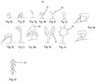
- FIGS. 5 a - sillustrate various embodiments of the surface-mounted protrusions of the device of the present invention.
- FIGS. 6 a - cis a CAD drawing of a prototype device having conical projections with mushroom-shaped protrusions.
- the present inventionis of a device which can be used to retrieve occlusions from a biological vessel.
- the present inventionis particularly useful for unblocking occluded arteries in various parts of the body including the brain.
- thrombus materialIn order to effectively clear an occlusion from an artery, thrombus material must be effectively penetrated, engaged/anchored, dislodged and retrieved from the vessel without releasing particles into circulation and while creating minimal irritation/damage to the vessel wall.
- Catheters having clot retrieval heads designed for maximizing clot engagement and retrievalare known in the art (e.g. U.S. Pat. Nos. 5,895,400, 7,731,731, 5,702,413, 5,827,304, 6,350,271, 6,692,504 or 7,008,434).
- cathetersmay be less effective for retrieving thrombus material or minimizing damage to the vessel wall since there is oftentimes a tradeoff between effective thrombus engagement and a need to minimize damage to, and vasospasm of the arterial walls.
- the present inventordescribed a catheter that is effective at penetrating, engaging, dislodging and retrieving thrombus material while minimizing damage to the vessel wall.
- This catheterincludes relatively soft leaf-like structures attached to a relatively rigid stem which is in turn mounted on an elongated body. The surface of the leaf-like structures is covered with macro and micro structures for enhancing engagement between the ‘leaf’ surface and the thrombus.
- extensionengagement between the catheter ‘leaves’ (herein generally referred to as “extension”) and occlusive material can be further enhanced by utilizing surface projections designed for specifically engaging a repeating structure forming a part of the occlusive material.
- a device for removing (clearing and optionally retrieving) occlusions in a biological vesselrefers to any vessel capable of supporting flow of a biological material.
- the vesselcan be a natural vessel or a synthetic vessel implanted in a body.
- vesselsinclude blood vessels such as veins or arteries, lymphatic vessels, urinary system vessels such as the urethra or ureters, seminal vessels, saliva ducts, bile ducts, synthetic vessels graft, such as arteriovenous (AV) graft and more.
- Occlusionsare any flow limiting blockages in the vessel which are caused by local buildup of atherosclerotic material, atherosclerotic emboli, migrating blood clots, biological stones, foreign bodies or the like.
- the deviceincludes an elongated body for delivering a plurality of extensions arranged around a distal portion of the elongated body into the biological vessel.
- the devicecan be configured as a catheter for use with a guidewire in clearing thrombus material from a blood vessel.
- the elongated bodycan include a longitudinal lumen sized for accepting a guidewire (e.g. 0.014′′, 0.018′′ or 0.035′′ or other guidewires).
- the lumencan be configured for use with over-the-wire, or rapid exchange systems.
- the devicecan also be delivered within a hollow catheter/delivery tube (guiding catheter).
- the catheter/delivery tubeis positioned using a guidewire which is then removed to allow positioning of the present device.
- the elongated bodycan be 10 to 200 cm in length with a width/diameter of 0.05-50 mm when in closed configuration (suitable for delivery within a 0.1-30 F sheath.
- the elongated bodyis preferably shaped as shaft (rod or tube) and is fabricated from any bio-compatible material, including, for example, alloys such as stainless steel, Nitinol or polymers such as Polyimide (PI), Polyether Block Amide (PEBA)-Pebax.
- the elongated bodyis preferably axially rigid in order to facilitate lodging of the distal portion (carrying the extensions) into the occlusion and yet flexible enough to facilitate navigation through torturous vessels while ensuring safety (e.g. blood vessels in the brain).
- Rigidity of the elongated body (catheter)is same range as catheters commonly used for navigating biological vessels such as blood vessels.
- the distal portion of the elongated bodyincludes extensions that project radially outward, preferably at an angle (of 0-90 degrees) towards the proximal end of the elongated body.
- the extensionscan be of any shape (rectangle, triangle, oval, polyangular-shaped, spiral, or a combination of several shapes including simple or complex shapes with fractal characteristics) and of any profile (round, oval, rectangle).
- the extensionscan be directly connected to the elongated device body, or connected thereto through a joint element (e.g. stem).
- the axial rigidity of the stem portion of the extensioncan be preferably anywhere from 0.1-100 grams (e.g. 10-90, 20-80, 30-70, 40-60) or more depending on the occlusion location, occlusion type and size, extension structure and material the stem is constructed from.
- the axial rigidity of the extensioncan be anywhere from 0.0-50 grams (e.g. 5-40, 10-30, 20-25) or more depending on the occlusion location, occlusion type and size and the structure and material the extension is constructed from.
- the extensions and optionally stemsare preferably elastically deformable and fabricated from elastomeric material such as thermoplastic elastomers (TPEs), silicone, other plastics or metal alloys such as Nitinol. Elasticity is selected such that when the device is advanced distally into an occlusion (thrombus) within the biological vessel, the extensions fold against the elongated body due to the forces exerted by the occlusion/thrombus mass. This enables the extensions to penetrate an occlusion (e.g. thrombus) in the vessel without crossing or deploying distally outside to the thrombus mass and lodge therein.
- TPEsthermoplastic elastomers
- siliconeother plastics or metal alloys
- NitinolNitinol
- the extensionsWhen the device is pulled in a proximal direction, the extensions deploy outward (to the angle set by the stems or the vessel wall limitation) due to the drag forces exerted by the occlusion (thrombus) mass thereby enabling the device to engage/anchor to the occlusion material, dislodge it from the vessel wall and remove it.
- Typical dimensions for the extensionscan be 0.2-30 mm in length, 0.05-20 mm in width, 0.03-3 mm in thickness, with a single side surface area of 0.01-600 mm 2 .
- the stems portionscan be 0.1-20 mm in length, 0.02-20 mm in width, 0.03-3 mm in thickness.
- extensionscan be carried on the elongated body depending on the biological vessel, occlusion size and type and function of the device.
- a typical number of extensionscan range from 1-20 or more.
- the extensionscan be carried as pair, triplets etc on a fixed or swiveling joint.
- the internal surface (facing towards the elongated body) of the extensionsis preferably concave in order to increase the surface area thereof and the drag/resistance force exerted on the internal surface by the thrombus mass.
- Such a concave configurationalso increases the ability of the extensions to collect (scoop) the occlusion material.
- the exterior surface of the extensionsis preferably convex to facilitate delivery within the vessel and lodging of the projections into the occlusion while folded in a “close configuration” (arrow like) due to the drag forces exerted on the extensions by the occlusion material when the extensions are advanced into the occlusion.
- Each extensioncan also fold in half lengthwise to further improve penetration into the occlusion material. Such folding can occur during use, in accordance with the mechanical forces exerted upon the extensions by the occlusion material and the vessel wall.
- the distal portion (tip) of the extensionis preferably curved inward in order to minimize trauma/damage to the vessel when the device is navigated within the blood vessels.
- the tipscan be fabricated from a very soft material (softer than the rest of the leaf-like structure).
- the inward curving tipscan also facilitate hooking of the projections into the occlusion material.
- the inner (and optionally outer) surface of the extensionsincludes surface mounted projections arranged as an array of specific size and distribution in order to enable the extensions to engage a repeating structure on the surface of the occlusion.
- the outer surface of the extensionscan be textured with numerous rounded bumps (several microns to several hundred microns in height and diameter) or hills and valleys or coated with a low friction coating (e.g. Parylene, polydimethylsiloxane) in order to minimize the contact area and overall friction between the outer surface of the extensions and the vessel wall. This enables the device to slide better against the vessel wall when navigated through the torturous cerebral vasculature.
- a low friction coatinge.g. Parylene, polydimethylsiloxane
- a blood clot or thrombus( FIG. 1 a ) includes a fibrin mesh ( FIG. 1 b ) with entrapped blood cells and platelets.
- the fibrin meshserves as the thrombus “skeleton structure” and provides stability as well as imparting a gel-like property to the blood clot.
- the fibrin fibersare organized in a 3D mesh configuration with an average pore size of 0.1-50 microns. The fiber diameter is between 50-500 nanometer.
- the distribution of the projections on the surface of the extension and the shape and size of each projectionmust be designed to enable the following:
- the projectionsare preferably arranged as an array of at least 100 projections (anywhere from several hundred to several millions projections per cm 2 of surface area) spaced apart by 0.01-500 microns (at the surface-contacting base).
- the arraycan be of any shape (circular, triangular, square etc) and can include one or more types (shapes) of projections.
- a projectioncan be 0.001-5,000 microns in height (length from base to tip) with a uniform or varying diameter or width throughout its length.
- Each projectioncan be angled at 90 degrees or less with respect to the surface of the extension in the direction of the base, tip or sides of the extension.
- the arraycan include projections that are identical or different with respect to degree of angulation and/or direction of angulation.
- the projectionscan be simple (e.g. cylindrical rod) or complex (e.g. ‘Christmas tree’ or ‘mushroom’) in shape and can include surface coating (composition for enhancing attachment to occlusion) or surface texturing (e.g. “fractal-like” texturing, e.g. gecko-like texturing).
- the unique configuration of the extensions and projections of the present deviceprovides several advantages in clearing occlusions in a biological vessel.
- the stem portionprevents the projections from flipping over thereby ensuring that a pulling force at the handle/proximal part of the device is efficiently converted to engagement/anchoring force.
- the extensionswill flip over in order to prevent injury or retention of the device.
- the projections and protrusionswill ensure that the thrombus remains attached to the extension.
- Dislodgement of occlusion materialthe pulling force at the handle/proximal part of the catheter is also efficiently converted to a proximal movement of the catheter-occlusion complex.
- the extensionscan be designed such that the forces applied thereby are matched to the type and location of occlusion.
- the forces applied by the extensions on the occlusionare a function of the occlusion material, size and the properties of the occlusion and the vessel surrounding it, thus minimizing unnecessary force and distortion of the thrombus natural configuration.
- cooperative engagement between numerous projections and occlusion materialfurther enhances attachment of extensions to the occlusion.
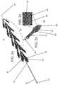
- FIG. 2 aillustrates a thrombus retrieval device which is referred to herein as device 10 .
- Device 10is configured suitable for entering, engaging/anchoring, dislodging and collecting thrombus material from a blood vessel and in particular small blood vessels of the brain, as well as other blood vessels.
- Device 10includes an elongated body 12 having a handle 14 (user engaged portion) at proximal end 16 and extensions 18 ( 16 shown) attached to a distal portion 20 .
- Elongated body 12includes a nose cone 22 for facilitating non-traumatic delivery into a vessel and also allows penetration into the occlusion/thrombus.
- Extensions 18are preferably arranged singly or as pairs (arrangements including 3, 4, 5, 6 or more projections are also possible) around distal portion 20 , with each single or pair rotated 0-180 degrees from an adjacent single pair.
- FIG. 2 billustrates an isolated extension 18 showing extension body 24 attached to a connector 26 via stem 27 .
- Connector 26can be glued or mechanically coupled to elongated body 12 .
- connector 26is a cylindrical connector which is fitted around elongated body 12 and fixedly attached thereto or allowed to swivel.
- Extension 18can alternatively be connected directly to elongated body 12 without use of a connector.
- Device 10can further include a web like element interposed between extensions 18 . Such an element can supplement the ability of device 10 to capture/harvest dislodged occlusion material.
- Extension body 24is leaf-shaped and includes an inward curving tip 28 for minimizing damage or irritation to the vessel wall when device 10 is pushed and pulled within the vessel.
- Inward curving tip 28also functions to facilitate lodging of extensions 18 into occlusion material (e.g. thrombus material) when device 10 is pulled in a proximal direction.
- occlusion materiale.g. thrombus material
- inner surface 30 of extension body 24is concave to increase surface contact area and drag forces when the device is pulled proximally and to scoop the occlusion material dislodged from the vessel wall.
- Inner surface 30can also be textured (e.g. micro/nano structures, not shown) to enhance surface contact area at the macro/micro/molecular level.
- Outer surface 32 of extension body 24( FIG. 2 a ) is convex to decrease drag forces when extensions 18 penetrate the thrombus mass.
- the convex outer surface 32also allows extensions 18 to fold into a compact streamlined configuration for delivery into the vessel and occlusion. Additional hydrodynamic streamlining of extensions 18 may be effected by providing outer surface 32 with one or more bumps/protrusions/channels etc.
- Extensions 18can be fabricated from a single material or from two or more materials.
- extensionscan be molded from a single material (e.g. silicone, teflon, nylon and any other elastomer, metal alloys such as Nitinol or elastomer with combination with metal alloys such as Nitinol), with the differential rigidity provided by varying the durometer of the material (e.g. molding stem 27 and optionally connector 26 from a different structure, a silicone having a higher Shore A value or increased thickness, or by using a different material or a combination of different materials).
- a single materiale.g. silicone, teflon, nylon and any other elastomer, metal alloys such as Nitinol or elastomer with combination with metal alloys such as Nitinol
- the differential rigidityprovided by varying the durometer of the material (e.g. molding stem 27 and optionally connector 26 from a different structure, a silicone having a higher Shore A value or increased
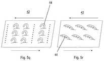
- FIG. 2 cis a magnification of inner surface 30 of extension body 24 (of the region circled in FIG. 2 b ) showing array 42 including a plurality of projections 44 .
- Array 42can be attached to a smooth or textured surface (such as the textured surface described above).
- Projections 44can be fabricated from the same material as the extensions 18 , or from a different material.
- suitable materials for construction of extension 18include silicone, teflon, nylon and any other elastomer, metal alloys such as Nitinol or elastomer with combination with metal alloys such as Nitinol.
- the projectionscan be attached to the surface, co formed therewith, or deposited thereupon using well known plasma deposition approaches.
- FIGS. 3 a - cillustrate a portion of device 10 , an extension 18 thereof and a magnified view of inner surface 30 of extension 18 showing projections.
- FIGS. 3 d - eare magnified views illustrating engagement between hook-like projections 44 and a fibrin mesh (M) component of a thrombus.
- Mfibrin mesh
- Hook-like projections 44can be 0.3-3.0 microns long, 0.2-1 microns in diameter, with a hook angle of 30-90 degrees relatively to the surface.
- the radius of curvature of the hook portioncan be 0.2-1.0 microns.
- projections 44When configured as hooks, projections 44 are designed to penetrate through the openings in the fibrin mesh and hook onto the fibrin fiber when device 10 is retracted. Cooperative hooking of several projections 44 would substantially increase the engagement force between extension 18 and the thrombus mass thereby enabling retrieval of the thrombus mass when device 10 is retracted out of the vasculature.
- FIGS. 4 a - cillustrate a portion of device 10 , an extension 18 thereof and a magnified view of inner surface 30 of extension 18 showing cylindrical (rod-like) projections 44 .
- FIGS. 4 d - eare magnified views illustrating engagement between cylindrical projections 44 and a fibrin mesh component of a thrombus. Cylindrical projections 44 have a size similar to that of hook-like projections described above.
- Cylindrical projections 44are designed to penetrate through the openings in the fibrin mesh and provide a large region of perpendicular contact between projections 44 and the fibrin fibers. Cooperative penetrations of several projections 44 through several openings in the fibrin mesh substantially increase the surface contact area and the engagement force between extension 18 and the thrombus mass thereby enabling retrieval of the thrombus mass when device 10 is retracted out of the vasculature.
- Cylindrical projections 44preferably include surface texturing or protrusions 45 (e.g. downward-pointing protrusions, see FIGS. 5 b, d, k, m and n ) which engage the fibrin fiber when device 10 is retracted.
- surface texturing or protrusions 45e.g. downward-pointing protrusions, see FIGS. 5 b, d, k, m and n .
- FIGS. 5 a - sillustrate several embodiments of projections 44 .
- Each embodimentis characterized by a specific configuration which facilitates engagement between projection 44 and the fibrin mesh.
- projection 44can be configured with side or downward pointing side protrusions 45 ( FIGS. 5 b, d and 5 k - n ), a bulbous or mushroom-shaped tip ( FIG. 5 j ), a branching tip ( FIG. 5 o ), a loop-gate (e.g. ‘carabiner’) lock ( FIG. 5 p ), an upright or inverted tree-like structure ( FIGS. 5 b, d and 5 c respectively), sideward or downward projecting hair-like structures ( FIG. 5 s ), comb-like structure, scales, and the like.
- a projection 44can include one or more of these structures arranged along a length thereof.
- the present devicecan include extensions 18 on which projections 44 are oriented in different directions, or include extensions having tips 46 (e.g. FIG. 5 c - d, m ) that guide projections 44 into the openings of the fibrin mesh.
- This structural asymmetry of an array 42enables engagement with the mesh through one or more directions and thus can maximize engagement when the specific orientation of the fibrin mesh with respect to an extension 18 is unknown.
- device 10typically includes a number of extensions 18 , having various configurations of array 42 on several extensions 18 again maximizes the statistical probability of mesh penetration by projections 44 .
- the embodiment of device 10 of FIG. 2 ais configured for use in clearing obstructions in a blood vessel, preferably a small brain artery that is 0.5-7 millimeter in diameter.
- elongated body 12 of device 10is preferably 10-200 centimeter in length, 0.5-7 millimeter in diameter when in closed configuration, while extensions 18 are preferably 0.2-30 mm in length.
- the length of extension body 24is preferably 0.1-30 mm and the width (at the widest thereof) is preferably 0.05-20 mm.
- Stem portion 27is preferably 0.1-20 mm in length and 0.02-20 mm in width (at the base).
- Extensions 18can be folded against elongated body 12 to an overall diameter of 0.5-7 millimeter. When folded, device 10 can be packed into a 1.5-22 F sheath for delivery through an access site. Once pushed out of the sheath, extensions 18 are folded outward to a position constrained by stem portion 27 (or vessel wall) while distal portion 20 is advanced to the site of occlusion. Since extension body 24 includes a non-traumatic tip 28 (fabricated from a soft material such as silicone), advancing device 10 in the distal direction (towards occlusion) does not traumatize or irritate the vessel wall. Once in position, pulling on handle/proximal catheter part 14 deploys extensions 18 to an angle limited by stem portions 27 or the vessel wall. Such an angle can be 90 degrees or less, preferably 30-45 degrees. At such an angle, tip 28 is angled inward to eliminate trauma and irritation to vessel wall.
- a non-traumatic tip 28fabricated from a soft material such as silicone
- extensions 18permits the device to automatically adapt to the inner diameter of the blood vessel in which device 10 is situated.
- Stem portion 27 and/or extension body 24can also be configured such that when folded against elongated body 12 , the longitudinal axis of extension body 24 is angled with respect to the longitudinal axis of elongated body 12 . This increases the exposure of inner surface 30 to the biological fluid in the vessel and to the occlusion material and increases drag and likelihood of deployment when device 10 is pulled in a proximal direction.
- a roll anglecan also be added such that each extension 18 has an “angle of attack” relative to the movement vector (angle range 0-90 degrees) i.e. to the anterior edge of extension body 24 relative to movement of device 10 .
- the angle of attack in the forward motion(when device 10 is pushed towards occlusion) will have hydrodynamic features and a curve design that will ensure an ability to optimally penetrate and minimally disrupt the thrombus structure.
- the angle of attack(which is the opposite edge) can be shaped in a more acute curve structure in order to allow optimal drag forces of the thrombus on each extension 18 thereby ensuring opening thereof.
- Extensions 18can also be configured to spiral around elongated body 12 .
- extensions 18 and of projections 44can be configured according to the biological vessel and occlusion properties. For example, there are two type of thrombus occlusions, a ‘red’ thrombus (fresh, acute whole blood thrombus) and a ‘white’ thrombus (relatively chronic embedded with cholesterol and calcium). Extensions 18 of device 10 as well as projections 44 can be configured with rigidity properties that match the viscosity ranges of the thrombus.
- device 10When configured as a catheter, device 10 includes a lumen for accepting a guidewire for guiding device 10 to a target occlusion within a vessel.
- the lumencan traverse the entire length of elongated body 12 (when use with an over-the-wire system) to an guidewire inlet opening in a proximal end of elongated body or alternatively, lumen can traverse a portion thereof (when used with a rapid exchange system) to a guidewire inlet opening at a side wall along a length of elongated body 12 .
- the lumencan also include one or more holes or other opening along a portion of elongated body proximal to extensions 18 .
- Such holescan be in fluid communication with an opening at distal end and would thus enable blood to flow around the occlusion mass once extensions 18 penetrate the occlusion and the distal end crosses the occlusion and is positioned at its distal side.
- a handle 14 or proximal portion of elongated body 12can be used to guide device 10 (whether over a wire or not) through the vessel and position distal portion 20 at a site of occlusion.
- Device 10can also include radio-opaque markers (e.g. gold, platinum, iridium or combined with the polymer itself or other radio-opaque markers) mounted on the distal end of elongated body 12 (at distal end).
- radio-opaque markerse.g. gold, platinum, iridium or combined with the polymer itself or other radio-opaque markers
- the markerscan be mounted on ends of extensions 18 (e.g. at tips 28 ).
- extensions 18extend out and thus when visualized (fluoroscopy) the markers are a predetermined distance apart (e.g. several millimeters).
- distal portion 20is positioned inside an occlusion, extensions 18 fold against elongated body 12 and thus when visualized (fluoroscopy) the distance between the markers is reduced.
- one of the markerscan be mounted on a foldable wire (e.g. Nitinol, platinum, other metal alloy or polymer wires) extending radially outward from elongated body 12 while a second marker can be attached to elongated body 12 .
- a foldable wiree.g. Nitinol, platinum, other metal alloy or polymer wires
- the marker wireis folded against elongated body 12 and brought into proximity to the second marker and optionally a third marker.
- the distance between the markerscan be visualized (fluoroscopy) to determine the extent of folding of the extension.
- Marker materiale.g. iridium or platinum
- Marker materialcan also be included in the material used to fabricate extensions 18 in order to facilitate identification thereof by a surgeon.
- the markersassist the clinician in determining the correct placement of device 10 within a blood vessel and indicate when distal portion 20 enters an occlusion and extensions 18 are lodged therein.
- inner surface 30 and/or projections 44can be coated with a substance that can bind the occlusion material.
- inner surface 30 and/or projections 44can be coated with fibrin or fibrin derivatives.
- Device 10can be used to clear a thrombus from an artery as follows. A guide catheter or guidewire is advanced from an access site (e.g. in a femoral artery) to the carotid artery under angiography. Device 10 is then inserted over-the-wire or through the guide catheter and navigated to the site of the thrombus. The surgeon then advances the distal end of device 10 into the thrombus until the distal end of device 10 reaches the distal end of the thrombus (as visualized via the radio-opaque markers described above). The surgeon then applies a gentle pulling force on device 10 to open extensions 18 and lodge and engage/anchor them within the thrombus. The device is then pulled along with the trapped thrombus.
- a guide catheter or guidewireis advanced from an access site (e.g. in a femoral artery) to the carotid artery under angiography. Device 10 is then inserted over-the-wire or through the guide catheter and navigated to the site
- Device 10 of the present inventioncan also be configured for use in clearing any type of occlusion from any biological vessels.
- the present devicewould be designed with surface projections that match the specific architecture of the occlusion.
- Prior art deviceswhich utilize macrostructures (e.g. hooks, bristles) to pierce through and engage the thrombus are more likely to cause embolic events since piercing through the thrombus mass can lead to thrombus disintegration.
- macrostructurese.g. hooks, bristles
- the present deviceencapsulates the thrombus and externally engages it through numerous points of contact using texture-specific micro and nano structures positioned on the surface of leaf-like extensions.
- engagement of the thrombus massdoes not compromise the integrity of the thrombus and use thereof may not require additional use of embolic protection or entrapment devices such as aspirators and traps which complicate and lengthen the procedure and can lead to serious complications such as vessel injury.
- OWL MC-2old World Labs
- OWL MC-2old World Labs
- additive manufacturingprovides several advantages in manufacturing of the present device:
- any shape projection and/or protrusioncan be manufactured to match any occlusion texture/composition
- (v) device or projection portion thereofcould be printed in-hospital to match specific patient needs (e.g. vessel size, occlusion type).
- FIGS. 6 a - cillustrate a configuration of the present device which is optimized for additive manufacturing.
- the portion of the device shown in FIG. 6 aincludes a tube with 6 pairs of extensions (leaves).
- the tube and extensionsare printed as a mono-structure and can be connected to a microcatheter for use (carrier tube can be fitted over a microcatheter).
- carrier tubecan be fitted over a microcatheter.
- This specific designis optimized for removing occlusions in 2.5 mm blood vessels.
- the extension pairsare rotationally offset 90 degrees from each other to ensure optimized occlusion engagement and collection.
- the inner surface of each extensionis manufactured with projections ( 44 ) which are conical in shape and are randomly yet homogenously distributed on the surface ( FIG. 6 b ). Since these projections are 3D printed (along with the extension and carrier tube), exact structure and dimensions can be achieved.
- each projectionis ‘printed’ with surface protrusions ( 45 ) which are mushroom-shaped (stalk and cap with rounded mushroom ‘cap’) and are 4 microns in height, 2 microns in diameter (at base) and 3 microns in diameter (at top). Average distance between protrusions is 10 microns.
- the size and shape parameters of the device shown in FIGS. 6 a - ccan be varied according to the occlusive material and patient.
- Occluding materialse.g. blood clot in its various types, biological stones, foreign body and more
- the size of the occluded vesselalso varies from patient to patient.
- the overall shape and size of the device as well as the shape and size of the extensions, projections and protrusionscan be matched to the patient and/or occlusion.
- the size of the vessel (diameter) and the shape, size and texture of the occlusive materialcan be determined from noninvasive imaging (including CT, MRI, Ultra Sound, Nuclear medicine and more); sampling (biopsy, microscopy) can be used to determine the composition of the occlusive material.
- noninvasive imagingincluding CT, MRI, Ultra Sound, Nuclear medicine and more
- samplingbiopsy, microscopy
- a suitable matching device designwill be generated (including size and geometrical configuration or extensions, projections and protrusions) and printed using additive manufacturing.
- This approachcould be used in real time in a hospital setting to manufacture and employ a patient-specific device optimized for retrieving a specific occlusion in a specific vessel.
Landscapes
- Health & Medical Sciences (AREA)
- Surgery (AREA)
- Life Sciences & Earth Sciences (AREA)
- Heart & Thoracic Surgery (AREA)
- Nuclear Medicine, Radiotherapy & Molecular Imaging (AREA)
- Vascular Medicine (AREA)
- Engineering & Computer Science (AREA)
- Biomedical Technology (AREA)
- Orthopedic Medicine & Surgery (AREA)
- Medical Informatics (AREA)
- Molecular Biology (AREA)
- Animal Behavior & Ethology (AREA)
- General Health & Medical Sciences (AREA)
- Public Health (AREA)
- Veterinary Medicine (AREA)
- Surgical Instruments (AREA)
Abstract
Description
- Resolution: 100 nm;
- Precision: 100 nm mechanical and software capability;
- Accuracy: ±50 nm
- Repeatability: 99%
- Build Volume: 6×6×6 in
- Build Speed: 1 inch3/hr.
- Build Materials: Photopolymer
Claims (12)
Priority Applications (1)
| Application Number | Priority Date | Filing Date | Title |
|---|---|---|---|
| US15/528,110US10772647B2 (en) | 2015-01-28 | 2016-01-25 | Device and method for removing occlusions in a biological vessel |
Applications Claiming Priority (3)
| Application Number | Priority Date | Filing Date | Title |
|---|---|---|---|
| US201562108602P | 2015-01-28 | 2015-01-28 | |
| PCT/IL2016/050073WO2016120864A2 (en) | 2015-01-28 | 2016-01-25 | Device and method for removing occlusions in a biological vessel |
| US15/528,110US10772647B2 (en) | 2015-01-28 | 2016-01-25 | Device and method for removing occlusions in a biological vessel |
Publications (2)
| Publication Number | Publication Date |
|---|---|
| US20170311966A1 US20170311966A1 (en) | 2017-11-02 |
| US10772647B2true US10772647B2 (en) | 2020-09-15 |
Family
ID=56544496
Family Applications (1)
| Application Number | Title | Priority Date | Filing Date |
|---|---|---|---|
| US15/528,110Active2036-04-28US10772647B2 (en) | 2015-01-28 | 2016-01-25 | Device and method for removing occlusions in a biological vessel |
Country Status (8)
| Country | Link |
|---|---|
| US (1) | US10772647B2 (en) |
| EP (1) | EP3250132B1 (en) |
| JP (1) | JP6741674B2 (en) |
| CN (1) | CN107405140B (en) |
| CA (1) | CA2973125C (en) |
| ES (1) | ES2998017T3 (en) |
| IL (1) | IL252225B (en) |
| WO (1) | WO2016120864A2 (en) |
Cited By (9)
| Publication number | Priority date | Publication date | Assignee | Title |
|---|---|---|---|---|
| US20220341139A1 (en)* | 2021-04-23 | 2022-10-27 | Kamran Yazdani | Hair entrapment filter system |
| US11553935B2 (en) | 2019-12-18 | 2023-01-17 | Imperative Care, Inc. | Sterile field clot capture module for use in thrombectomy system |
| US11850349B2 (en) | 2018-07-06 | 2023-12-26 | Incept, Llc | Vacuum transfer tool for extendable catheter |
| US12171917B1 (en) | 2024-01-08 | 2024-12-24 | Imperative Care, Inc. | Devices for blood capture and reintroduction during aspiration procedure |
| US12201506B2 (en) | 2019-12-18 | 2025-01-21 | Imperative Care, Inc. | Rotatable thrombus engagement tool |
| US12232838B2 (en) | 2021-08-12 | 2025-02-25 | Imperative Care, Inc. | Method of robotically performing a neurovascular procedure |
| USD1077996S1 (en) | 2021-10-18 | 2025-06-03 | Imperative Care, Inc. | Inline fluid filter |
| US12343479B2 (en) | 2016-02-24 | 2025-07-01 | Incept, Llc | Neurovascular catheter |
| US12350443B2 (en) | 2019-03-29 | 2025-07-08 | Incept, Llc | Enhanced flexibility neurovascular catheter |
Families Citing this family (5)
| Publication number | Priority date | Publication date | Assignee | Title |
|---|---|---|---|---|
| ES2671045T3 (en) | 2012-01-15 | 2018-06-04 | Triticum Ltd. | Device to remove occlusions of a biological vessel |
| WO2016120864A2 (en) | 2015-01-28 | 2016-08-04 | Triticum Ltd. | Device and method for removing occlusions in a biological vessel |
| CN109875642A (en)* | 2019-03-11 | 2019-06-14 | 恩脉(上海)医疗科技有限公司 | A thrombus removal device |
| US11896250B2 (en) | 2020-08-31 | 2024-02-13 | Covidien Lp | Aspiration systems and methods, and expanding-mouth catheters |
| CN114403983A (en)* | 2021-12-22 | 2022-04-29 | 江苏大学 | Thrombus extraction device and design method thereof |
Citations (76)
| Publication number | Priority date | Publication date | Assignee | Title |
|---|---|---|---|---|
| US4643184A (en) | 1982-09-29 | 1987-02-17 | Mobin Uddin Kazi | Embolus trap |
| US4765332A (en) | 1986-07-14 | 1988-08-23 | Medinnovations, Inc. | Pullback atherectomy catheter system |
| US5003657A (en) | 1987-07-08 | 1991-04-02 | Medipro | Device for unblocking intubation tubes and tracheotomy cannulas in vivo |
| US5009659A (en) | 1989-10-30 | 1991-04-23 | Schneider (Usa) Inc. | Fiber tip atherectomy catheter |
| US5129910A (en) | 1991-07-26 | 1992-07-14 | The Regents Of The University Of California | Stone expulsion stent |
| US5133733A (en) | 1989-11-28 | 1992-07-28 | William Cook Europe A/S | Collapsible filter for introduction in a blood vessel of a patient |
| US5192290A (en) | 1990-08-29 | 1993-03-09 | Applied Medical Resources, Inc. | Embolectomy catheter |
| WO1994023787A1 (en) | 1993-04-22 | 1994-10-27 | Rammler David H | Sampling balloon catheter |
| US5370653A (en) | 1993-07-22 | 1994-12-06 | Micro Therapeutics, Inc. | Thrombectomy method and apparatus |
| US5421832A (en) | 1989-12-13 | 1995-06-06 | Lefebvre; Jean-Marie | Filter-catheter and method of manufacturing same |
| US5522825A (en) | 1993-03-25 | 1996-06-04 | Ferromec S.A. | Medical instrument for the removal of deposits formed on the inner walls of the arteries or veins |
| US5702413A (en) | 1996-01-11 | 1997-12-30 | Scimed Life Systems, Inc. | Curved bristle atherectomy device and method |
| US5769960A (en) | 1995-07-05 | 1998-06-23 | Nirmel; Chittaranjan N. | Device and method for manually removing a clog containing fibrous matter |
| US5827304A (en) | 1995-11-16 | 1998-10-27 | Applied Medical Resources Corporation | Intraluminal extraction catheter |
| US5836032A (en) | 1997-09-30 | 1998-11-17 | Hondo; Leslie H. | Apparatus for removing hair from a drain |
| US5895400A (en) | 1997-06-27 | 1999-04-20 | Abela; George S. | Catheter with bristles |
| US5902263A (en) | 1997-02-12 | 1999-05-11 | Prolifix Medical, Inc. | Apparatus and method for removing stenotic material from stents |
| CN1216929A (en) | 1996-02-02 | 1999-05-19 | 血管转换公司 | Method and apparatus for blocking flow through blood vessels |
| US5984965A (en) | 1997-08-28 | 1999-11-16 | Urosurge, Inc. | Anti-reflux reinforced stent |
| US6027514A (en) | 1997-12-17 | 2000-02-22 | Fox Hollow Technologies, Inc. | Apparatus and method for removing occluding material from body lumens |
| USD435944S1 (en) | 2000-02-09 | 2001-01-02 | Eugene H. Luoma | Drain cleaner strip |
| US6254571B1 (en) | 1996-04-18 | 2001-07-03 | Applied Medical Resources Corporation | Remote clot management |
| US20010016962A1 (en) | 1998-11-25 | 2001-08-30 | Neosci Medical, Inc. | Cleaning brush for medical devices |
| US6350271B1 (en) | 1999-05-17 | 2002-02-26 | Micrus Corporation | Clot retrieval device |
| US6458139B1 (en) | 1999-06-21 | 2002-10-01 | Endovascular Technologies, Inc. | Filter/emboli extractor for use in variable sized blood vessels |
| US20020147458A1 (en) | 2001-04-09 | 2002-10-10 | Scimed Life Systems, Inc. | Compressible atherectomy burr |
| JP2003010193A (en) | 2001-07-02 | 2003-01-14 | Terumo Corp | Wire and medical instrument for removing foreign body in blood vessel |
| JP2003038500A (en) | 2001-08-03 | 2003-02-12 | Mti Kk | Shaft with brush for foreign matter removal in tubular organ |
| CN1501825A (en) | 2001-01-09 | 2004-06-02 | �������ɭ | Embolectomy catheters and methods of treatment |
| US6775873B2 (en) | 2000-02-09 | 2004-08-17 | Eugene H. Luoma | Apparatus for removing hair from a drain |
| US20040215222A1 (en) | 2003-04-25 | 2004-10-28 | Michael Krivoruchko | Intravascular material removal device |
| US20050216050A1 (en) | 2000-06-29 | 2005-09-29 | Concentric Medical, Inc. | Systems, methods and devices for removing obstructions from a blood vessel |
| WO2005102184A1 (en) | 2004-04-22 | 2005-11-03 | Angioslide Ltd. | Catheter |
| CA2571343A1 (en) | 2004-06-24 | 2006-02-02 | Boston Scientific Limited | Apparatus for treating occluded vasculature |
| DE102004040868A1 (en) | 2004-08-23 | 2006-03-09 | Miloslavski, Elina | Device for removing thrombi |
| US20060184194A1 (en) | 2005-02-15 | 2006-08-17 | Cook Incorporated | Embolic protection device |
| USD532978S1 (en) | 2005-02-16 | 2006-12-05 | Marie Robinson | Flexible compressible brush for cleaning drinking straws |
| US20060287667A1 (en) | 2005-06-17 | 2006-12-21 | Abela George S | Catheter for clearing passages in a patient |
| US20070066991A1 (en) | 2005-09-16 | 2007-03-22 | Cook Incorporated | Embolic protection device |
| US20070118165A1 (en) | 2004-03-08 | 2007-05-24 | Demello Jonathan R | System and method for removal of material from a blood vessel using a small diameter catheter |
| US20080033423A1 (en) | 2005-02-02 | 2008-02-07 | Peacock James C Iii | Total vascular occlusion treatment system and method |
| US20080167678A1 (en) | 2007-01-05 | 2008-07-10 | Hesham Morsi | Embolectomy Catheter |
| US20080262495A1 (en) | 2004-03-31 | 2008-10-23 | Orthofix S.R.L | Intramedullary Nail Comprising Elements of Shape-Memory Material |
| US20090054805A1 (en) | 2005-07-26 | 2009-02-26 | Precision Thoracic Corporation | Minimally invasive methods and apparatus |
| US20090112239A1 (en)* | 2007-10-31 | 2009-04-30 | Specialized Vascular Technologies, Inc. | Sticky dilatation balloon and methods of using |
| GB2459481A (en) | 2008-04-23 | 2009-10-28 | Invivo Technology Ltd | Expanding medical collet |
| USD610761S1 (en) | 2009-06-19 | 2010-02-23 | Charles Gengler | Drain unclogger |
| US20100249815A1 (en) | 2009-03-25 | 2010-09-30 | Cook Incorporated | Everted sheath thrombectomy device |
| US20110144671A1 (en) | 2009-06-18 | 2011-06-16 | Cardiovascular Systems, Inc. | Atherectomy device, system and method having a bi-directional distal expandable ablation element |
| CN102170833A (en) | 2008-08-08 | 2011-08-31 | 因赛普特有限责任公司 | Apparatus and methods for accessing and removing material from body lumens |
| US8021379B2 (en) | 2008-01-11 | 2011-09-20 | Medtronic Vascular, Inc. | Obstruction removal system |
| US8021380B2 (en) | 2008-01-11 | 2011-09-20 | Dustin Thompson | Obstruction removal system |
| US8034095B2 (en) | 2008-08-29 | 2011-10-11 | Cook Medical Technologies Llc | Intraluminal system for retrieving an implantable medical device |
| US20120005849A1 (en) | 2010-07-09 | 2012-01-12 | George Tash and Debra B. Tash, as Trustees of the Community Trust created | Hand-Operated Drain Snake With Auger |
| USD659918S1 (en) | 2010-12-09 | 2012-05-15 | S.C. Johnson & Son, Inc. | Wand |
| US20120172656A1 (en) | 2011-01-05 | 2012-07-05 | Walters Daniel A | Percutaneous heart pump |
| WO2012110619A1 (en) | 2011-02-17 | 2012-08-23 | Acandis Gmbh & Co Kg | Medical device for removing concretions, and system having a medical device of this kind |
| WO2013105099A2 (en) | 2012-01-15 | 2013-07-18 | Triticum Ltd. | Device and method for removing occlusions in a biological vessel |
| US8545499B2 (en) | 2009-09-28 | 2013-10-01 | Zimmer, Inc. | Expandable intramedullary rod |
| US20140135814A1 (en) | 2000-06-29 | 2014-05-15 | Concentric Medical, Inc. | Systems, methods and devices for removing obstructions from a blood vessel |
| US8784434B2 (en) | 2012-11-20 | 2014-07-22 | Inceptus Medical, Inc. | Methods and apparatus for treating embolism |
| US8814892B2 (en) | 2010-04-13 | 2014-08-26 | Mivi Neuroscience Llc | Embolectomy devices and methods for treatment of acute ischemic stroke condition |
| US8852205B2 (en) | 2011-03-09 | 2014-10-07 | Neuravi Limited | Clot retrieval device for removing occlusive clot from a blood vessel |
| US20150018859A1 (en) | 2013-07-12 | 2015-01-15 | Inceptus Medical, Llc | Methods and apparatus for treating pulmonary embolism |
| US20150119896A1 (en) | 2008-06-08 | 2015-04-30 | Hotspur Technologies, Inc. | Apparatus and mehtods for removing obstructive material from body lumens |
| US20150164630A1 (en)* | 2008-01-04 | 2015-06-18 | Eric Johnson | Filter support members |
| US9113857B2 (en) | 2012-01-31 | 2015-08-25 | The Trustees Of Columbia University In The City Of New York | Sampling catheter devices, methods, and systems |
| US9131988B2 (en) | 2012-09-28 | 2015-09-15 | Avent, Inc. | Self positioning tracheal tube clearance mechanism using skives |
| US9138307B2 (en) | 2007-09-14 | 2015-09-22 | Cook Medical Technologies Llc | Expandable device for treatment of a stricture in a body vessel |
| US9194114B2 (en) | 2013-01-08 | 2015-11-24 | Marvin Petry | Drain pipe cleaning device and method |
| US9216034B2 (en) | 2011-10-04 | 2015-12-22 | Angioworks Medical, B.V. | Devices and methods for percutaneous endarterectomy |
| US9217243B2 (en) | 2013-05-02 | 2015-12-22 | Patrick Gwen | Drain cleaning tool |
| US9220499B2 (en) | 2010-10-28 | 2015-12-29 | Covidien Lp | Wound closure device including barbed pins |
| US20160051261A1 (en) | 2013-04-29 | 2016-02-25 | Regenerative Sciences, Llc | Percutaneous Tendon-Muscle-Ligament Approximation Device |
| US20160221050A1 (en) | 2015-01-30 | 2016-08-04 | Pf Waterworks Lp | Drain Cleaning Apparatus |
| WO2016120864A2 (en) | 2015-01-28 | 2016-08-04 | Triticum Ltd. | Device and method for removing occlusions in a biological vessel |
Family Cites Families (2)
| Publication number | Priority date | Publication date | Assignee | Title |
|---|---|---|---|---|
| US6663650B2 (en) | 2000-06-29 | 2003-12-16 | Concentric Medical, Inc. | Systems, methods and devices for removing obstructions from a blood vessel |
| US20060058837A1 (en) | 2004-09-10 | 2006-03-16 | Arani Bose | System and method for treating ischemic stroke |
- 2016
- 2016-01-25WOPCT/IL2016/050073patent/WO2016120864A2/ennot_activeCeased
- 2016-01-25CACA2973125Apatent/CA2973125C/enactiveActive
- 2016-01-25USUS15/528,110patent/US10772647B2/enactiveActive
- 2016-01-25JPJP2017540079Apatent/JP6741674B2/enactiveActive
- 2016-01-25CNCN201680019053.5Apatent/CN107405140B/enactiveActive
- 2016-01-25EPEP16742884.6Apatent/EP3250132B1/enactiveActive
- 2016-01-25ESES16742884Tpatent/ES2998017T3/enactiveActive
- 2017
- 2017-05-11ILIL252225Apatent/IL252225B/enunknown
Patent Citations (88)
| Publication number | Priority date | Publication date | Assignee | Title |
|---|---|---|---|---|
| US4643184A (en) | 1982-09-29 | 1987-02-17 | Mobin Uddin Kazi | Embolus trap |
| US4765332A (en) | 1986-07-14 | 1988-08-23 | Medinnovations, Inc. | Pullback atherectomy catheter system |
| US5003657A (en) | 1987-07-08 | 1991-04-02 | Medipro | Device for unblocking intubation tubes and tracheotomy cannulas in vivo |
| US5009659A (en) | 1989-10-30 | 1991-04-23 | Schneider (Usa) Inc. | Fiber tip atherectomy catheter |
| US5133733A (en) | 1989-11-28 | 1992-07-28 | William Cook Europe A/S | Collapsible filter for introduction in a blood vessel of a patient |
| US5421832A (en) | 1989-12-13 | 1995-06-06 | Lefebvre; Jean-Marie | Filter-catheter and method of manufacturing same |
| US5192290A (en) | 1990-08-29 | 1993-03-09 | Applied Medical Resources, Inc. | Embolectomy catheter |
| US5129910A (en) | 1991-07-26 | 1992-07-14 | The Regents Of The University Of California | Stone expulsion stent |
| US5522825A (en) | 1993-03-25 | 1996-06-04 | Ferromec S.A. | Medical instrument for the removal of deposits formed on the inner walls of the arteries or veins |
| WO1994023787A1 (en) | 1993-04-22 | 1994-10-27 | Rammler David H | Sampling balloon catheter |
| US5370653A (en) | 1993-07-22 | 1994-12-06 | Micro Therapeutics, Inc. | Thrombectomy method and apparatus |
| US5769960A (en) | 1995-07-05 | 1998-06-23 | Nirmel; Chittaranjan N. | Device and method for manually removing a clog containing fibrous matter |
| US5827304A (en) | 1995-11-16 | 1998-10-27 | Applied Medical Resources Corporation | Intraluminal extraction catheter |
| US5702413A (en) | 1996-01-11 | 1997-12-30 | Scimed Life Systems, Inc. | Curved bristle atherectomy device and method |
| CN1216929A (en) | 1996-02-02 | 1999-05-19 | 血管转换公司 | Method and apparatus for blocking flow through blood vessels |
| US6254571B1 (en) | 1996-04-18 | 2001-07-03 | Applied Medical Resources Corporation | Remote clot management |
| US5902263A (en) | 1997-02-12 | 1999-05-11 | Prolifix Medical, Inc. | Apparatus and method for removing stenotic material from stents |
| US5895400A (en) | 1997-06-27 | 1999-04-20 | Abela; George S. | Catheter with bristles |
| US5984965A (en) | 1997-08-28 | 1999-11-16 | Urosurge, Inc. | Anti-reflux reinforced stent |
| US5836032A (en) | 1997-09-30 | 1998-11-17 | Hondo; Leslie H. | Apparatus for removing hair from a drain |
| US6027514A (en) | 1997-12-17 | 2000-02-22 | Fox Hollow Technologies, Inc. | Apparatus and method for removing occluding material from body lumens |
| US20010016962A1 (en) | 1998-11-25 | 2001-08-30 | Neosci Medical, Inc. | Cleaning brush for medical devices |
| US6692504B2 (en) | 1999-05-17 | 2004-02-17 | Micrus Corporation | Clot retrieval device |
| US6350271B1 (en) | 1999-05-17 | 2002-02-26 | Micrus Corporation | Clot retrieval device |
| US7008434B2 (en) | 1999-05-17 | 2006-03-07 | Micrus Corporation | Clot retrieval device |
| US6458139B1 (en) | 1999-06-21 | 2002-10-01 | Endovascular Technologies, Inc. | Filter/emboli extractor for use in variable sized blood vessels |
| USD435944S1 (en) | 2000-02-09 | 2001-01-02 | Eugene H. Luoma | Drain cleaner strip |
| US6775873B2 (en) | 2000-02-09 | 2004-08-17 | Eugene H. Luoma | Apparatus for removing hair from a drain |
| US20050216050A1 (en) | 2000-06-29 | 2005-09-29 | Concentric Medical, Inc. | Systems, methods and devices for removing obstructions from a blood vessel |
| US8062307B2 (en) | 2000-06-29 | 2011-11-22 | Concentric Medical, Inc. | Systems, methods and devices for removing obstructions from a blood vessel |
| US20140135814A1 (en) | 2000-06-29 | 2014-05-15 | Concentric Medical, Inc. | Systems, methods and devices for removing obstructions from a blood vessel |
| CN1501825A (en) | 2001-01-09 | 2004-06-02 | �������ɭ | Embolectomy catheters and methods of treatment |
| US20020147458A1 (en) | 2001-04-09 | 2002-10-10 | Scimed Life Systems, Inc. | Compressible atherectomy burr |
| JP2003010193A (en) | 2001-07-02 | 2003-01-14 | Terumo Corp | Wire and medical instrument for removing foreign body in blood vessel |
| JP2003038500A (en) | 2001-08-03 | 2003-02-12 | Mti Kk | Shaft with brush for foreign matter removal in tubular organ |
| US20040215222A1 (en) | 2003-04-25 | 2004-10-28 | Michael Krivoruchko | Intravascular material removal device |
| US7416555B2 (en) | 2003-04-25 | 2008-08-26 | Medtronic Vascular, Inc. | Intravascular material removal device |
| US20070118165A1 (en) | 2004-03-08 | 2007-05-24 | Demello Jonathan R | System and method for removal of material from a blood vessel using a small diameter catheter |
| US20080262495A1 (en) | 2004-03-31 | 2008-10-23 | Orthofix S.R.L | Intramedullary Nail Comprising Elements of Shape-Memory Material |
| WO2005102184A1 (en) | 2004-04-22 | 2005-11-03 | Angioslide Ltd. | Catheter |
| CA2571343A1 (en) | 2004-06-24 | 2006-02-02 | Boston Scientific Limited | Apparatus for treating occluded vasculature |
| DE102004040868A1 (en) | 2004-08-23 | 2006-03-09 | Miloslavski, Elina | Device for removing thrombi |
| CN101035474A (en) | 2004-08-23 | 2007-09-12 | 菲诺克斯有限公司 | Device for the removal of thromboses |
| US20080033423A1 (en) | 2005-02-02 | 2008-02-07 | Peacock James C Iii | Total vascular occlusion treatment system and method |
| US20060184194A1 (en) | 2005-02-15 | 2006-08-17 | Cook Incorporated | Embolic protection device |
| USD532978S1 (en) | 2005-02-16 | 2006-12-05 | Marie Robinson | Flexible compressible brush for cleaning drinking straws |
| US20060287667A1 (en) | 2005-06-17 | 2006-12-21 | Abela George S | Catheter for clearing passages in a patient |
| US7731731B2 (en) | 2005-06-17 | 2010-06-08 | Abela George S | Catheter for clearing passages in a patient |
| US20090054805A1 (en) | 2005-07-26 | 2009-02-26 | Precision Thoracic Corporation | Minimally invasive methods and apparatus |
| US20070066991A1 (en) | 2005-09-16 | 2007-03-22 | Cook Incorporated | Embolic protection device |
| US20080167678A1 (en) | 2007-01-05 | 2008-07-10 | Hesham Morsi | Embolectomy Catheter |
| US9138307B2 (en) | 2007-09-14 | 2015-09-22 | Cook Medical Technologies Llc | Expandable device for treatment of a stricture in a body vessel |
| US20090112239A1 (en)* | 2007-10-31 | 2009-04-30 | Specialized Vascular Technologies, Inc. | Sticky dilatation balloon and methods of using |
| US20150164630A1 (en)* | 2008-01-04 | 2015-06-18 | Eric Johnson | Filter support members |
| US8021379B2 (en) | 2008-01-11 | 2011-09-20 | Medtronic Vascular, Inc. | Obstruction removal system |
| US8021380B2 (en) | 2008-01-11 | 2011-09-20 | Dustin Thompson | Obstruction removal system |
| GB2459481A (en) | 2008-04-23 | 2009-10-28 | Invivo Technology Ltd | Expanding medical collet |
| US20150119896A1 (en) | 2008-06-08 | 2015-04-30 | Hotspur Technologies, Inc. | Apparatus and mehtods for removing obstructive material from body lumens |
| CN102170833A (en) | 2008-08-08 | 2011-08-31 | 因赛普特有限责任公司 | Apparatus and methods for accessing and removing material from body lumens |
| US8034095B2 (en) | 2008-08-29 | 2011-10-11 | Cook Medical Technologies Llc | Intraluminal system for retrieving an implantable medical device |
| US20100249815A1 (en) | 2009-03-25 | 2010-09-30 | Cook Incorporated | Everted sheath thrombectomy device |
| US20110144671A1 (en) | 2009-06-18 | 2011-06-16 | Cardiovascular Systems, Inc. | Atherectomy device, system and method having a bi-directional distal expandable ablation element |
| USD610761S1 (en) | 2009-06-19 | 2010-02-23 | Charles Gengler | Drain unclogger |
| US8545499B2 (en) | 2009-09-28 | 2013-10-01 | Zimmer, Inc. | Expandable intramedullary rod |
| US20140371782A1 (en) | 2010-04-13 | 2014-12-18 | Mivi Neuroscience Llc | Embolectomy devices and methods for treatment of acute ischemic stroke condition |
| US8814892B2 (en) | 2010-04-13 | 2014-08-26 | Mivi Neuroscience Llc | Embolectomy devices and methods for treatment of acute ischemic stroke condition |
| US8365337B2 (en) | 2010-07-09 | 2013-02-05 | George Tash and Debra B. Tash, As Trustees of the Community Trust | Hand-operated drain snake with auger |
| US20120005849A1 (en) | 2010-07-09 | 2012-01-12 | George Tash and Debra B. Tash, as Trustees of the Community Trust created | Hand-Operated Drain Snake With Auger |
| US9220499B2 (en) | 2010-10-28 | 2015-12-29 | Covidien Lp | Wound closure device including barbed pins |
| USD659918S1 (en) | 2010-12-09 | 2012-05-15 | S.C. Johnson & Son, Inc. | Wand |
| US20120172656A1 (en) | 2011-01-05 | 2012-07-05 | Walters Daniel A | Percutaneous heart pump |
| WO2012110619A1 (en) | 2011-02-17 | 2012-08-23 | Acandis Gmbh & Co Kg | Medical device for removing concretions, and system having a medical device of this kind |
| US8852205B2 (en) | 2011-03-09 | 2014-10-07 | Neuravi Limited | Clot retrieval device for removing occlusive clot from a blood vessel |
| US9216034B2 (en) | 2011-10-04 | 2015-12-22 | Angioworks Medical, B.V. | Devices and methods for percutaneous endarterectomy |
| US20140309657A1 (en) | 2012-01-15 | 2014-10-16 | Triticum Ltd. | Device and method for removing occlusions in a biological vessel |
| CN104093369A (en) | 2012-01-15 | 2014-10-08 | 小麦公司 | Device and treatment for removing embolism in biological vessels |
| US20180235645A1 (en) | 2012-01-15 | 2018-08-23 | Triticum Ltd. | Device and method for removing occlusions in a biological vessel |
| WO2013105099A2 (en) | 2012-01-15 | 2013-07-18 | Triticum Ltd. | Device and method for removing occlusions in a biological vessel |
| US9113857B2 (en) | 2012-01-31 | 2015-08-25 | The Trustees Of Columbia University In The City Of New York | Sampling catheter devices, methods, and systems |
| US9131988B2 (en) | 2012-09-28 | 2015-09-15 | Avent, Inc. | Self positioning tracheal tube clearance mechanism using skives |
| US9717519B2 (en) | 2012-11-20 | 2017-08-01 | Inceptus Medical, Llc | Methods and apparatus for treating embolism |
| US8784434B2 (en) | 2012-11-20 | 2014-07-22 | Inceptus Medical, Inc. | Methods and apparatus for treating embolism |
| US9194114B2 (en) | 2013-01-08 | 2015-11-24 | Marvin Petry | Drain pipe cleaning device and method |
| US20160051261A1 (en) | 2013-04-29 | 2016-02-25 | Regenerative Sciences, Llc | Percutaneous Tendon-Muscle-Ligament Approximation Device |
| US9217243B2 (en) | 2013-05-02 | 2015-12-22 | Patrick Gwen | Drain cleaning tool |
| US20150018859A1 (en) | 2013-07-12 | 2015-01-15 | Inceptus Medical, Llc | Methods and apparatus for treating pulmonary embolism |
| WO2016120864A2 (en) | 2015-01-28 | 2016-08-04 | Triticum Ltd. | Device and method for removing occlusions in a biological vessel |
| US20160221050A1 (en) | 2015-01-30 | 2016-08-04 | Pf Waterworks Lp | Drain Cleaning Apparatus |
Non-Patent Citations (45)
| Title |
|---|
| Advisory Action Before the Filing of an Appeal Brief dated Mar. 20, 2017 From the US Patent and Trademark Office Re. U.S. Appl. No. 14/315,352. (3 pages). |
| Advisory Action Before the Filing of an Appeal Brief dated Sep. 12, 2017 From the US Patent and Trademark Office Re. U.S. Appl. No. 14/315,352. (3 pages). |
| Chiu, Hecht, Duong, Wu, Tawil. Permeability of Three-Dimensional Fibrin Constructs Corresponding to Fibrinogen and Thrombin Concentrations. Department of Bioengineering UCLA. 2012:1(1). DOI:10,1089/biores.2012.0211 (Year: 2012).* |
| Communication Pursuant to Article 94(3) EPC dated Jun. 23, 2017 From the European Patent Office Re. Application No. 13735641.6. (5 Pages). |
| Communication Pursuant to Article 94(3) EPC dated Mar. 10, 2016 From the European Patent Office Re. Application No. 13735641.6. |
| Communication Under Rule 71(3) EPC dated Dec. 15, 2017 From the European Patent Office Re. Application No. 13735641.6. (37 Pages). |
| Decision of Rejection dated Dec. 12, 2017 From the Japan Patent Office Re. Application No. 2014-551729. (2 Pages). |
| Examination Report dated Apr. 12, 2017 From the Instituto Mexicano de la Propiedad Industril, Direccion Divisional de Patentes, IMPI Re. Application No. MX/a/2014/008474 and Its Translation Into English. (6 Pages). |
| Final Official Action dated May 27, 2020 from the US Patent and Trademark Office Re. U.S. Appl. No. 15/961,909. (11 pages). |
| International Preliminary Report on Patentability dated Aug. 10, 2017 From the International Bureau of WIPO Re. Application No. PCT/IL2016/050073. (9 Pages). |
| International Preliminary Report on Patentability dated Jul. 24, 2014 From the International Bureau of WIPO Re. Application No. PCT/IL2013/050049. |
| International Search Report and the Written Opinion dated Jul. 19, 2013 From the International Searching Authority Re. Application No. PCT/IL2013/050049. |
| International Search Report and the Written Opinion dated Jul. 29, 2016 From the International Searching Authority Re. Application No. PCT/IL2016/050073. |
| Invitation to Pay Additional Fees dated May 9, 2016 From the International Searching Authority Re. Application No. PCT/IL2016/050073. |
| Notice of Allowance dated Mar. 2, 2018 From the US Patent and Trademark Office Re. U.S. Appl. No. 14/315,352. (17 pages). |
| Notice of Reason for Rejection dated Aug. 30, 2019 From the Japan Patent Office Re. Application No. 2017-540079 and Its Translation Into English. (8 Pages). |
| Notice of Reason for Rejection dated Jan. 7, 2020 From the Japan Patent Office Re. Application No. 2017-540079 and Its Translation Into English. (6 Pages). |
| Notice of Reasons for Rejection dated May 30, 2017 From the Japan Patent Office Re. Application No. 2014-551729. (5 Pages). |
| Notice of Reasons for Rejection dated Nov. 15, 2016 From the Japan Patent Office Re. Application No. 2014-551729 and Its Translation Into English. (18 Pages). |
| Notification of Decision of Rejection dated Jul. 22, 2019 From the State Intellectual Property Office of the People's Republic of China Re. Application No. 201610379472.1. (5 Pages). |
| Notification of Office Action and Search Report dated Dec. 20, 2019 From the National Intellectual Property Administration of the People's Republic of China Re. Application No. 201680019053.5 and Its Translation Into English.(19 Pages). |
| Notification of Office Action and Search Report dated Dec. 4, 2015 From the State Intellectual Property Office of the People's Republic of China Re. Application No. 201380005571.8 and Its Summary of Office Action in English. |
| Notification of Office Action and Search Report dated Jul. 22, 2019 From the State Intellectual Property Office of the People's Republic of China Re. Application No. 201680019053.5 and a Summary of the Notification of Office Action Into English.(19 Pages). |
| Notification of Office Action dated Apr. 1, 2016 From the State Intellectual Property Office of the People's Republic of China Re. Application No. 201380005571.8 and Its Summary in English. |
| Notification of Office Action dated Aug. 14, 2018 From the State Intellectual Property Office of the People's Republic of China Re. Application No. 201610379472.1 and Its Summary in English. (5 Pages). |
| Notification of Office Action dated Feb. 3, 2019 From the State Intellectual Property Office of the People's Republic of China Re. Application No. 201610379472.1 and Its Translation of Office Action Into English. (10 Pages). |
| Notification of Office Action dated Jan. 25, 2018 From the State Intellectual Property Office of the People's Republic of China Re. Application No. 201610379472.1 and Its Translation into English. (12 Pages). |
| Notification of Office Action dated Jul. 5, 2016 From the State Intellectual Property Office of the People's Republic of China Re. Application No. 201380005571.8. |
| Office Action dated Jun. 6, 2018 From the Israel Patent Office Re. Application No. 233660 and Its Translation Into English. (4 Pages). |
| Office Action dated Mar. 7, 2018 From the Israel Patent Office Re. Application No. 233660 and Its Translation Into English. (5 Pages). |
| Official Action dated Feb. 14, 2020 From the US Patent and Trademark Office Re. U.S. Appl. No. 15/961,909. (48 pages). |
| Official Action dated Feb. 22, 2017 From the US Patent and Trademark Office Re. U.S. Appl. No. 14/315,352. (14 pages). |
| Official Action dated Jul. 28, 2017 From the US Patent and Trademark Office Re. U.S. Appl. No. 14/315,352. (14 pages). |
| Official Action dated Mar. 31, 2017 From the US Patent and Trademark Office Re. U.S. Appl. No. 14/315,352. (11 pages). |
| Official Action dated Oct. 18, 2017 From the US Patent and Trademark Office Re. U.S. Appl. No. 14/315,352. (13 Pages). |
| Official Action dated Oct. 25, 2016 From the US Patent and Trademark Office Re. U.S. Appl. No. 14/315,352. |
| Patent Examination Report dated Sep. 7, 2016 From the Australian Government, IP Australia Re. Application No. 2013208660. |
| Requisition by the Examiner dated Sep. 28, 2018 From the Innovation, Science and Economic Development Canada, Canadian Intellectual Property Office Re. Application No. 2,860,301. (4 Pages). |
| Restriction Official Action dated Aug. 8, 2016 From the US Patent and Trademark Office Re. U.S. Appl. No. 14/315,352. |
| Supplementary European Search Report and the European Search Opinion dated Aug. 24, 2018 From the European Patent Office Re. Application No. 16742884.6. (9 Pages). |
| Supplementary European Search Report and the European Search Opinion dated May 11, 2015 From the European Patent Office Re. Application No. 13735641.6. |
| Translation Dated Aug. 11, 2019 of Notification of Decision of Rejection dated Jul. 22, 2019 From the State Intellectual Property Office of the People's Republic of China Re. Application No. 201610379472.1. (5 Pages). |
| Translation of Decision of Rejection dated Dec. 12, 2017 From the Japan Patent Office Re. Application No. 2014-551729. (4 Pages). |
| Translation of Notice of Reasons for Rejection dated May 30, 2017 From the Japan Patent Office Re. Application No. 2014-551729. (11 Pages). |
| Translation of Notification of Office Action dated Jul. 5, 2016 From the State Intellectual Property Office of the People's Republic of China Re. Application No. 201380005571.8. |
Cited By (13)
| Publication number | Priority date | Publication date | Assignee | Title |
|---|---|---|---|---|
| US12343479B2 (en) | 2016-02-24 | 2025-07-01 | Incept, Llc | Neurovascular catheter |
| US11850349B2 (en) | 2018-07-06 | 2023-12-26 | Incept, Llc | Vacuum transfer tool for extendable catheter |
| US12350443B2 (en) | 2019-03-29 | 2025-07-08 | Incept, Llc | Enhanced flexibility neurovascular catheter |
| US11553935B2 (en) | 2019-12-18 | 2023-01-17 | Imperative Care, Inc. | Sterile field clot capture module for use in thrombectomy system |
| US11633272B2 (en) | 2019-12-18 | 2023-04-25 | Imperative Care, Inc. | Manually rotatable thrombus engagement tool |
| US11638637B2 (en) | 2019-12-18 | 2023-05-02 | Imperative Care, Inc. | Method of removing embolic material with thrombus engagement tool |
| US12201506B2 (en) | 2019-12-18 | 2025-01-21 | Imperative Care, Inc. | Rotatable thrombus engagement tool |
| US11927002B2 (en)* | 2021-04-23 | 2024-03-12 | Kamran Yazdani | Hair entrapment filter system |
| US20220341139A1 (en)* | 2021-04-23 | 2022-10-27 | Kamran Yazdani | Hair entrapment filter system |
| US12376928B2 (en) | 2021-08-12 | 2025-08-05 | Imperative Care, Inc. | Catheter drive system for supra-aortic access |
| US12232838B2 (en) | 2021-08-12 | 2025-02-25 | Imperative Care, Inc. | Method of robotically performing a neurovascular procedure |
| USD1077996S1 (en) | 2021-10-18 | 2025-06-03 | Imperative Care, Inc. | Inline fluid filter |
| US12171917B1 (en) | 2024-01-08 | 2024-12-24 | Imperative Care, Inc. | Devices for blood capture and reintroduction during aspiration procedure |
Also Published As
| Publication number | Publication date |
|---|---|
| WO2016120864A2 (en) | 2016-08-04 |
| EP3250132B1 (en) | 2024-08-14 |
| IL252225B (en) | 2022-01-01 |
| US20170311966A1 (en) | 2017-11-02 |
| IL252225A0 (en) | 2017-07-31 |
| CN107405140A (en) | 2017-11-28 |
| ES2998017T3 (en) | 2025-02-18 |
| CA2973125C (en) | 2023-07-04 |
| JP2018503465A (en) | 2018-02-08 |
| WO2016120864A3 (en) | 2016-09-22 |
| EP3250132A2 (en) | 2017-12-06 |
| EP3250132A4 (en) | 2018-09-26 |
| CN107405140B (en) | 2021-05-11 |
| EP3250132C0 (en) | 2024-08-14 |
| CA2973125A1 (en) | 2016-08-04 |
| JP6741674B2 (en) | 2020-08-19 |
Similar Documents
| Publication | Publication Date | Title |
|---|---|---|
| US10772647B2 (en) | Device and method for removing occlusions in a biological vessel | |
| JP6430674B2 (en) | Device for removing occlusions in a biological tube | |
| US11925369B2 (en) | Method for treating vascular occlusion | |
| EP3579765B1 (en) | Axial lengthening thrombus capture system | |
| US20070038226A1 (en) | Embolectomy procedures with a device comprising a polymer and devices with polymer matrices and supports | |
| EP3240491B1 (en) | Small fragment retrieval device | |
| EP3539485B1 (en) | Small fragment retrieval device | |
| US9101449B2 (en) | Filter removal device |
Legal Events
| Date | Code | Title | Description |
|---|---|---|---|
| AS | Assignment | Owner name:TRITICUM LTD., ISRAEL Free format text:ASSIGNMENT OF ASSIGNORS INTEREST;ASSIGNOR:BEN-AMI, DORON JACOB;REEL/FRAME:043050/0008 Effective date:20151120 | |
| STPP | Information on status: patent application and granting procedure in general | Free format text:DOCKETED NEW CASE - READY FOR EXAMINATION | |
| STPP | Information on status: patent application and granting procedure in general | Free format text:NON FINAL ACTION MAILED | |
| STPP | Information on status: patent application and granting procedure in general | Free format text:RESPONSE TO NON-FINAL OFFICE ACTION ENTERED AND FORWARDED TO EXAMINER | |
| STPP | Information on status: patent application and granting procedure in general | Free format text:FINAL REJECTION MAILED | |
| STPP | Information on status: patent application and granting procedure in general | Free format text:RESPONSE AFTER FINAL ACTION FORWARDED TO EXAMINER | |
| STPP | Information on status: patent application and granting procedure in general | Free format text:ADVISORY ACTION MAILED | |
| STPP | Information on status: patent application and granting procedure in general | Free format text:DOCKETED NEW CASE - READY FOR EXAMINATION | |
| STPP | Information on status: patent application and granting procedure in general | Free format text:NON FINAL ACTION MAILED | |
| STPP | Information on status: patent application and granting procedure in general | Free format text:RESPONSE TO NON-FINAL OFFICE ACTION ENTERED AND FORWARDED TO EXAMINER | |
| STPP | Information on status: patent application and granting procedure in general | Free format text:FINAL REJECTION MAILED | |
| STPP | Information on status: patent application and granting procedure in general | Free format text:ADVISORY ACTION MAILED | |
| STPP | Information on status: patent application and granting procedure in general | Free format text:DOCKETED NEW CASE - READY FOR EXAMINATION | |
| STPP | Information on status: patent application and granting procedure in general | Free format text:RESPONSE TO NON-FINAL OFFICE ACTION ENTERED AND FORWARDED TO EXAMINER | |
| STPP | Information on status: patent application and granting procedure in general | Free format text:PUBLICATIONS -- ISSUE FEE PAYMENT VERIFIED | |
| STCF | Information on status: patent grant | Free format text:PATENTED CASE | |
| MAFP | Maintenance fee payment | Free format text:PAYMENT OF MAINTENANCE FEE, 4TH YEAR, MICRO ENTITY (ORIGINAL EVENT CODE: M3551); ENTITY STATUS OF PATENT OWNER: MICROENTITY Year of fee payment:4 |