US10772620B2 - Adjustable motion limiter for a minimally invasive surgical device - Google Patents
Adjustable motion limiter for a minimally invasive surgical deviceDownload PDFInfo
- Publication number
- US10772620B2 US10772620B2US15/243,163US201615243163AUS10772620B2US 10772620 B2US10772620 B2US 10772620B2US 201615243163 AUS201615243163 AUS 201615243163AUS 10772620 B2US10772620 B2US 10772620B2
- Authority
- US
- United States
- Prior art keywords
- motion limiter
- adjustable motion
- minimally invasive
- invasive surgical
- cam surface
- Prior art date
- Legal status (The legal status is an assumption and is not a legal conclusion. Google has not performed a legal analysis and makes no representation as to the accuracy of the status listed.)
- Active, expires
Links
Images


Classifications
- A—HUMAN NECESSITIES
- A61—MEDICAL OR VETERINARY SCIENCE; HYGIENE
- A61B—DIAGNOSIS; SURGERY; IDENTIFICATION
- A61B17/00—Surgical instruments, devices or methods
- A61B17/04—Surgical instruments, devices or methods for suturing wounds; Holders or packages for needles or suture materials
- A61B17/0469—Suturing instruments for use in minimally invasive surgery, e.g. endoscopic surgery
- A—HUMAN NECESSITIES
- A61—MEDICAL OR VETERINARY SCIENCE; HYGIENE
- A61B—DIAGNOSIS; SURGERY; IDENTIFICATION
- A61B17/00—Surgical instruments, devices or methods
- A61B17/28—Surgical forceps
- A61B17/29—Forceps for use in minimally invasive surgery
- A61B17/2909—Handles
- A—HUMAN NECESSITIES
- A61—MEDICAL OR VETERINARY SCIENCE; HYGIENE
- A61B—DIAGNOSIS; SURGERY; IDENTIFICATION
- A61B17/00—Surgical instruments, devices or methods
- A61B17/04—Surgical instruments, devices or methods for suturing wounds; Holders or packages for needles or suture materials
- A61B17/06—Needles ; Sutures; Needle-suture combinations; Holders or packages for needles or suture materials
- A61B17/06004—Means for attaching suture to needle
- A61B2017/06042—Means for attaching suture to needle located close to needle tip
- A—HUMAN NECESSITIES
- A61—MEDICAL OR VETERINARY SCIENCE; HYGIENE
- A61B—DIAGNOSIS; SURGERY; IDENTIFICATION
- A61B90/00—Instruments, implements or accessories specially adapted for surgery or diagnosis and not covered by any of the groups A61B1/00 - A61B50/00, e.g. for luxation treatment or for protecting wound edges
- A61B90/03—Automatic limiting or abutting means, e.g. for safety
- A61B2090/033—Abutting means, stops, e.g. abutting on tissue or skin
- A61B2090/034—Abutting means, stops, e.g. abutting on tissue or skin abutting on parts of the device itself
Definitions
- the claimed inventionrelates to minimally invasive surgical devices, and more specifically to an adjustable motion limiter for minimally invasive surgical devices having an actuator.
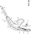
- FIG. 1illustrates one embodiment of a minimally invasive surgical device 20 .
- This particular device 20is a suturing device having an end effector 22 that includes a needle 24 .
- the needle 24is coupled to an actuator 26 , in this example, a handle which pivots on a pivot point 28 in the housing 30 .
- an actuator 26in this example, a handle which pivots on a pivot point 28 in the housing 30 .
- a handle 32which is part of the housing 30
- a tolerance stack 38is schematically illustrated to account for the fact that there are many different tolerances which can cause the amount of distance which the needle tip 34 moves to vary.
- the suturing device 20is equipped with a ferrule 40 which lies at the end of a suture 42 .
- the actuator 26moves the needle tip 34 across the tissue bite area 44 and into contact with the ferrule 40 , such that the ferrule 40 is engaged by interference contact with the needle tip 34 without undesired deformation of the ferrule 40 .
- the actuator 26can then be returned to its starting position by spring 46 , causing the needle 24 to draw the ferrule 40 and its suture 42 back through the tissue bite area 44 .
- FIGS. 2A and 2Bare enlarged views of the distal end of the device 20 from FIG. 1 illustrating what can happen if the needle tip 34 is advanced too far.
- the interference of the needle tip 34 and the ferrule 40causes the ferrule to flare out as the larger portion of the needle 24 is driven into contact with the ferrule 40 .
- the flared ferrule 40contacts a release spring 50 when it is not supposed to.
- thiscan jam the device or cause the ferrule 40 to release from the needle 24 when such release is not desired. In either case, the device does not work properly.
- the tolerance stackcan vary from unit to unit, so it would be advantageous to have a device and method to compensate for the effects of the tolerance stack, thereby ensuring reliable device operation.
- the adjustable motion limiterfor a minimally invasive surgical device is disclosed.
- the adjustable motion limiterincludes a cam surface and a positioning interface.
- the adjustable motion limiterhas a positioning interface comprising a grooved protrusion.
- the adjustable motion limiteralso has a cam surface comprising an arcuate surface and facing a direction which is substantially perpendicular to a direction the positioning interface faces.
- the adjustable motion limiterfurther has an adjustment key and one or more locking teeth.
- a minimally invasive surgical deviceis also disclosed.
- the minimally invasive surgical devicehas an end effector.
- the minimally invasive surgical devicealso has an actuator coupled to the end effector.
- the minimally invasive surgical devicefurther has an adjustable motion limiter.
- the adjustable motion limiterhas a cam surface configured to engage the actuator.
- the adjustable motion limiteralso has a housing interface.
- FIG. 1illustrates one embodiment of a minimally invasive surgical device.
- FIGS. 2A and 2Bare enlarged views of the distal end of the device 20 from FIG. 1 illustrating what can happen if the needle tip is advanced too far.
- FIGS. 3B, 3C, 3D, 3A, 3E, and 3Fare front, left, right, top, bottom, and upside-down back views, respectively, of one embodiment of an adjustable motion limiter for a minimally invasive surgical device.
- FIGS. 4A and 4Billustrate the adjustable motion limiter of FIGS. 3A-3F along with a schematic view of a minimally invasive surgical device in both a side and a perspective view, respectively.
- FIG. 5illustrates three possible positions for the cam surface of the adjustable motion limiter of FIGS. 3A-3F and the corresponding farthest travel possible for an actuator of a surgical device, depending on the position of the cam surface.
- FIG. 6is similar to FIG. 5 , however the location of the adjustable motion limiter has been modified.
- FIG. 7illustrates another embodiment of an adjustable motion limiter.
- FIGS. 8A-8Eare each further embodiments of an adjustable motion limiter.
- FIG. 8Fis an enlarged perspective view of the adjustable motion limiter of FIGS. 3A-3F .
- FIG. 8Gis an enlarged perspective view of the adjustable motion limiter of FIG. 7 .
- FIGS. 3B, 3C, 3D, 3A, 3E, and 3Fare front, left, right, top, bottom, and upside-down back views of one embodiment of an adjustable motion limiter 52 for a minimally invasive surgical device.
- the surgical device illustrated hereinis a surgical suturing device, but other types of minimally invasive surgical devices could benefit from the claimed invention, including, but not limited to mechanical fastener applicators.
- the adjustable motion limiterhas a cam surface 54 and a positioning interface 56 .
- the cam surface 54is a varying arcuate surface.
- Other embodimentsmay have other types of varying surfaces, including those which are continuously varying or discretely varying.
- the positioning interface 56 in this embodimentprotrudes in two opposite directions which are each substantially perpendicular to a direction which the cam surface 54 faces. While this embodiment has a positioning interface 56 which features two protrusions, other embodiments may have a positioning interface which has fewer or more protrusions. Still other embodiments may have positioning interfaces which are holes or depressions or a mixture of holes and protrusions.
- the adjustable motion limiter 52is configured so that the cam surface 54 will engage an actuator, while the positioning interface 56 is configured to engage a housing.
- the cam surfacemay be configured to engage a housing, while the positioning interface engages an actuator.
- the positioning interface 56is grooved 58 to help keep the motion limiter 52 from rotating once it is pressed into the portion of the handle which it engages.
- the positioning interface 56is also tapered to facilitate the pressing of the interface 56 into a portion of the handle by easing the adjustable motion limiter 52 into place.
- This embodiment of a motion limiter 52also has an adjustment key 60 which happens to be an oblong rounded shape. Other embodiments may have other keyed shapes.
- a toolmay be provided which can engage the adjustment key 60 in order to enable an assembler or an assembly machine to rotate the adjustable motion limiter 52 .
- the positioning interface 56may be capable of holding the adjustable motion limiter 52 in place on its own, some embodiments, such as the one illustrated in FIGS. 3A-3F may include one or more locking teeth 62 which can help grip the material which the positioning interface 56 is pressed into.
- FIGS. 4A and 4Billustrate the adjustable motion limiter 52 of FIGS. 3A-3F along with a schematic view of a minimally invasive surgical device 20 in both a side and a perspective view, respectively.
- the adjustable motion limiter 52is exploded away from the device housing/handle 30 / 32 in order to show a boss 64 which has been formed in the housing 30 in order to receive the positioning interface 56 . Only one half of the handle 32 is illustrated here for convenience, but it should be understood that a corresponding boss may be provided on the other handle half if the positioning interface 56 also extends in that direction.
- the adjustable motion limiter 52may be rotated before being pressed into the boss 64 to position the cam surface 54 at different profiles relative to the actuator 26 .
- Three potential profiles out of numerous profilesare shown in FIG. 5 to illustrate the benefit of the adjustable motion limiter 52 .
- the first profileis illustrated as a thinner solid line. In this first position, the cam surface 54 does not reach out towards the actuator 26 as far as the other illustrated positions. Accordingly, the actuator may be moved back towards the handle 32 farther than when the other profiles are used before the actuator 26 contacts the cam surface 54 of the adjustable motion limiter 52 . This profile position would allow the needle tip 34 to travel farther when the actuator is engaged fully.
- the second profileis illustrated as a thicker, occasionally broken line.
- the cam surface 54reaches out farther towards the actuator 26 than the other illustrated positions. Accordingly, the actuator may be moved back towards the handle 32 less than when the other profiles are sued before the actuator 26 contacts the cam surface 54 of the adjustable motion limiter 52 . This profile position would allow the needle tip 34 to travel less when the actuator is fully engaged.
- the third profileis illustrated as a thin, regularly broken line. This third position is located between the first and second positions, and as such, the actuator may be moved a distance between those possible in the first and second positions before the actuator contacts the cam surface 54 of the adjustable motion limiter 52 . This profile position would allow the needle tip 34 to travel a distance between those possible with the first and second positions when the actuator is fully engaged.
- An operator or automated assembly fixturemay be used to rotate the adjustable motion limiter 52 while the actuator is fully engaged to a desired amount of travel.
- the desired amount of travelcan be determined by looking at the position of the needle tip 34 relative to the device tip, a ferrule holder of the device, or even a ferrule installed in the device.
- the adjustable motion limiter 52should be rotated until the cam surface contacts the actuator 26 in this desired full-travel position, and then the adjustable motion limiter 52 can be fixed in place by one or more methods which include, but are not limited to pressing, welding, and gluing the limiter to the housing 30 .
- FIG. 6illustrates another potential position on the housing where the motion limiter 52 could be fixed to the housing 30 .
- the motion limiter 52could be fixed to the actuator in a place where it would contact a known part of the housing.
- FIG. 7illustrates another embodiment of an adjustable motion limiter 66 , this one having holes 68 for its positioning interface.
- a corresponding protrusion 70is provided on the handle. Adjustment of the cam surface 72 of the motion limiter 66 would occur similarly to the examples described above.
- FIGS. 8A-8Gillustrate different non-limiting embodiments of an adjustable motion limiter.
- the adjustable motion limiter 74 of FIG. 8Ais like that of FIGS. 3A-3F , except the motion limiter 74 does not have an adjustment key or locking teeth.
- the adjustable motion limiter 76 of FIG. 8Bis like that of FIGS. 3A-3F , except the motion limiter 76 does not have an adjustment key or grooved protrusions. Instead, the protrusions 77 which make up the positioning interface are smooth. Locking teeth, however, are provided.
- the adjustable motion limiter 78 of FIG. 8Cis like that of FIGS. 3A-3F , except the motion limiter 78 does not have an adjustment key.
- FIG. 8Dis like that of FIGS. 3A-3F , except the motion limiter 80 does not have locking teeth.
- the adjustable motion limiter 82 of FIG. 8Eis like that of FIGS. 3A-3F , except the motion limiter 82 does not have grooved protrusions. Instead, the protrusions 83 which make up the positioning interface are smooth.
- the adjustable motion limiter 52 of FIG. 8Fis like that of FIGS. 3A-3F .
- the adjustable motion limiter 66 of FIG. 8Gis like that of FIG. 7 .
Landscapes
- Health & Medical Sciences (AREA)
- Life Sciences & Earth Sciences (AREA)
- Surgery (AREA)
- Heart & Thoracic Surgery (AREA)
- Engineering & Computer Science (AREA)
- Biomedical Technology (AREA)
- Nuclear Medicine, Radiotherapy & Molecular Imaging (AREA)
- Medical Informatics (AREA)
- Molecular Biology (AREA)
- Animal Behavior & Ethology (AREA)
- General Health & Medical Sciences (AREA)
- Public Health (AREA)
- Veterinary Medicine (AREA)
- Surgical Instruments (AREA)
Abstract
Description
Claims (18)
Priority Applications (1)
| Application Number | Priority Date | Filing Date | Title |
|---|---|---|---|
| US15/243,163US10772620B2 (en) | 2015-08-20 | 2016-08-22 | Adjustable motion limiter for a minimally invasive surgical device |
Applications Claiming Priority (2)
| Application Number | Priority Date | Filing Date | Title |
|---|---|---|---|
| US201562207880P | 2015-08-20 | 2015-08-20 | |
| US15/243,163US10772620B2 (en) | 2015-08-20 | 2016-08-22 | Adjustable motion limiter for a minimally invasive surgical device |
Publications (2)
| Publication Number | Publication Date |
|---|---|
| US20170049441A1 US20170049441A1 (en) | 2017-02-23 |
| US10772620B2true US10772620B2 (en) | 2020-09-15 |
Family
ID=58051042
Family Applications (1)
| Application Number | Title | Priority Date | Filing Date |
|---|---|---|---|
| US15/243,163Active2036-12-30US10772620B2 (en) | 2015-08-20 | 2016-08-22 | Adjustable motion limiter for a minimally invasive surgical device |
Country Status (2)
| Country | Link |
|---|---|
| US (1) | US10772620B2 (en) |
| WO (1) | WO2017031493A1 (en) |
Families Citing this family (4)
| Publication number | Priority date | Publication date | Assignee | Title |
|---|---|---|---|---|
| US11234735B2 (en) | 2019-05-20 | 2022-02-01 | Covidien Lp | Tissue resecting instrument including variable drive |
| US11413057B2 (en) | 2019-06-27 | 2022-08-16 | Covidien Lp | Tissue resecting instruments including auxiliary vacuum features |
| US11849924B2 (en) | 2019-06-27 | 2023-12-26 | Covidien Lp | Tissue resecting instruments including tissue collection cartridges |
| US11571233B2 (en) | 2020-11-19 | 2023-02-07 | Covidien Lp | Tissue removal handpiece with integrated suction |
Citations (28)
| Publication number | Priority date | Publication date | Assignee | Title |
|---|---|---|---|---|
| US3682175A (en)* | 1969-10-01 | 1972-08-08 | Paul Halter | Squirting gun and dosing device therefor |
| US4164225A (en) | 1977-12-28 | 1979-08-14 | Johnson & Lorenz, Inc. | Surgical suturing instrument |
| US4406654A (en)* | 1982-02-22 | 1983-09-27 | American Cyanamid Company | Adjustable feeding device for the administration of dosages of gels and pastes to farm animals |
| US4546859A (en)* | 1977-09-27 | 1985-10-15 | American Hospital Supply Corporation | Adjustable stop for dispensing syringe |
| US4865029A (en)* | 1986-04-24 | 1989-09-12 | Eye Research Institute Of Retina Foundation | Endophotocoagulation probe |
| US4887756A (en)* | 1984-05-07 | 1989-12-19 | Puchy David P | Surgical stapler providing variable degree of staple closure |
| US5282806A (en)* | 1992-08-21 | 1994-02-01 | Habley Medical Technology Corporation | Endoscopic surgical instrument having a removable, rotatable, end effector assembly |
| US5364365A (en)* | 1993-08-30 | 1994-11-15 | Surgin Surgical Instrumentation, Inc. | Safety device for laparoscopic instruments |
| US5431666A (en) | 1994-02-24 | 1995-07-11 | Lasersurge, Inc. | Surgical suture instrument |
| US5562686A (en) | 1995-04-19 | 1996-10-08 | United States Surgical Corporation | Apparaus and method for suturing body tissue |
| US5582615A (en)* | 1995-10-30 | 1996-12-10 | Pilling Weck, Incorporated | Handle for surgical clip applicator systems |
| US5766183A (en)* | 1996-10-21 | 1998-06-16 | Lasersurge, Inc. | Vascular hole closure |
| US20020095175A1 (en)* | 1998-02-24 | 2002-07-18 | Brock David L. | Flexible instrument |
| US20020107530A1 (en) | 2001-02-02 | 2002-08-08 | Sauer Jude S. | System for endoscopic suturing |
| US6533796B1 (en) | 2000-10-11 | 2003-03-18 | Lsi Solutions, Inc. | Loader for surgical suturing instrument |
| US20040059358A1 (en)* | 2002-09-20 | 2004-03-25 | Kortenbach Juergen A. | Methods for the surgical application of a fastener and the endoluminal treatment of gastroesphageal reflux disease (GERD) |
| US20040068272A1 (en) | 1999-11-19 | 2004-04-08 | Sauer Jude S. | System for wound closure |
| US20050234479A1 (en) | 2002-05-22 | 2005-10-20 | Orthopaedic Biosystems Ltd., Inc. A Delaware Corporation | Suture passing surgical instrument |
| US7211093B2 (en) | 2004-01-14 | 2007-05-01 | Lsi Solutions, Inc. | Sew-right running stitch instrument |
| US20070255296A1 (en) | 2006-04-26 | 2007-11-01 | Lsi Solutions, Inc. | Medical instrument to place a pursestring suture, open a hole and pass a guidewire |
| US20090222027A1 (en) | 2008-02-28 | 2009-09-03 | Lsi Solutions, Inc. | Ferrule holder with suture relief lobes |
| US20110087255A1 (en)* | 2009-08-07 | 2011-04-14 | Mccormack Bruce M | Systems and methods for treatment of compressed nerves |
| US20110087218A1 (en)* | 2009-10-09 | 2011-04-14 | Ethicon Endo-Surgery, Inc. | Surgical instrument comprising first and second drive systems actuatable by a common trigger mechanism |
| US20110118758A1 (en) | 2009-11-19 | 2011-05-19 | Lsi Solutions, Inc. | Multi-fire suturing instrument with proximal ferrule release feature |
| US20120016383A1 (en) | 2010-07-13 | 2012-01-19 | Lsi Solutions, Inc. | Method and apparatus for closing an opening in thick, moving tissue |
| US8313496B2 (en) | 2001-02-02 | 2012-11-20 | Lsi Solutions, Inc. | System for endoscopic suturing |
| US8827136B2 (en)* | 2010-08-11 | 2014-09-09 | Covidien Lp | Endoscopic purse string surgical device |
| US9433431B2 (en) | 2011-03-30 | 2016-09-06 | Olympus Winter & Ibe Gmbh | Handle |
Family Cites Families (5)
| Publication number | Priority date | Publication date | Assignee | Title |
|---|---|---|---|---|
| US7118587B2 (en)* | 2001-04-06 | 2006-10-10 | Sherwood Services Ag | Vessel sealer and divider |
| US7105004B2 (en)* | 2002-10-21 | 2006-09-12 | Start Llc | One-hand locking and releasing handheld medical instrument |
| US7875040B2 (en)* | 2003-10-15 | 2011-01-25 | Femcare Limited | Visual indication of a trigger intermediate position on an applicator |
| US8617185B2 (en)* | 2007-02-13 | 2013-12-31 | P Tech, Llc. | Fixation device |
| GB0818101D0 (en)* | 2008-10-03 | 2008-11-05 | Femcare Nikomed Ltd | Applicator for surgical clips |
- 2016
- 2016-08-22WOPCT/US2016/048020patent/WO2017031493A1/ennot_activeCeased
- 2016-08-22USUS15/243,163patent/US10772620B2/enactiveActive
Patent Citations (36)
| Publication number | Priority date | Publication date | Assignee | Title |
|---|---|---|---|---|
| US3682175A (en)* | 1969-10-01 | 1972-08-08 | Paul Halter | Squirting gun and dosing device therefor |
| US4546859A (en)* | 1977-09-27 | 1985-10-15 | American Hospital Supply Corporation | Adjustable stop for dispensing syringe |
| US4164225A (en) | 1977-12-28 | 1979-08-14 | Johnson & Lorenz, Inc. | Surgical suturing instrument |
| US4406654A (en)* | 1982-02-22 | 1983-09-27 | American Cyanamid Company | Adjustable feeding device for the administration of dosages of gels and pastes to farm animals |
| US4887756A (en)* | 1984-05-07 | 1989-12-19 | Puchy David P | Surgical stapler providing variable degree of staple closure |
| US4865029A (en)* | 1986-04-24 | 1989-09-12 | Eye Research Institute Of Retina Foundation | Endophotocoagulation probe |
| US5282806A (en)* | 1992-08-21 | 1994-02-01 | Habley Medical Technology Corporation | Endoscopic surgical instrument having a removable, rotatable, end effector assembly |
| US5364365A (en)* | 1993-08-30 | 1994-11-15 | Surgin Surgical Instrumentation, Inc. | Safety device for laparoscopic instruments |
| US5431666A (en) | 1994-02-24 | 1995-07-11 | Lasersurge, Inc. | Surgical suture instrument |
| US5562686A (en) | 1995-04-19 | 1996-10-08 | United States Surgical Corporation | Apparaus and method for suturing body tissue |
| US5582615A (en)* | 1995-10-30 | 1996-12-10 | Pilling Weck, Incorporated | Handle for surgical clip applicator systems |
| US5766183A (en)* | 1996-10-21 | 1998-06-16 | Lasersurge, Inc. | Vascular hole closure |
| US6368334B1 (en) | 1996-10-21 | 2002-04-09 | Lasersurge, Inc. | Vascular hole closure |
| US8652149B2 (en) | 1996-10-21 | 2014-02-18 | Lsi Solutions, Inc. | Vascular hole closure |
| US20020095175A1 (en)* | 1998-02-24 | 2002-07-18 | Brock David L. | Flexible instrument |
| US20040068272A1 (en) | 1999-11-19 | 2004-04-08 | Sauer Jude S. | System for wound closure |
| US6533796B1 (en) | 2000-10-11 | 2003-03-18 | Lsi Solutions, Inc. | Loader for surgical suturing instrument |
| US20050165419A1 (en) | 2001-02-02 | 2005-07-28 | Sauer Jude S. | System for endoscopic suturing |
| US6997931B2 (en) | 2001-02-02 | 2006-02-14 | Lsi Solutions, Inc. | System for endoscopic suturing |
| US20020107530A1 (en) | 2001-02-02 | 2002-08-08 | Sauer Jude S. | System for endoscopic suturing |
| US8313496B2 (en) | 2001-02-02 | 2012-11-20 | Lsi Solutions, Inc. | System for endoscopic suturing |
| US20050234479A1 (en) | 2002-05-22 | 2005-10-20 | Orthopaedic Biosystems Ltd., Inc. A Delaware Corporation | Suture passing surgical instrument |
| US20040059358A1 (en)* | 2002-09-20 | 2004-03-25 | Kortenbach Juergen A. | Methods for the surgical application of a fastener and the endoluminal treatment of gastroesphageal reflux disease (GERD) |
| US7211093B2 (en) | 2004-01-14 | 2007-05-01 | Lsi Solutions, Inc. | Sew-right running stitch instrument |
| US7407505B2 (en) | 2004-01-14 | 2008-08-05 | Lsi Solutions, Inc. | Running stitch suturing device |
| US20100211083A1 (en) | 2006-04-26 | 2010-08-19 | Lsi Solutions, Inc. | Medical instrument to place a pursestring suture, open a hole and pass a guidewire |
| US7731727B2 (en) | 2006-04-26 | 2010-06-08 | Lsi Solutions, Inc. | Medical instrument to place a pursestring suture, open a hole and pass a guidewire |
| US20070255296A1 (en) | 2006-04-26 | 2007-11-01 | Lsi Solutions, Inc. | Medical instrument to place a pursestring suture, open a hole and pass a guidewire |
| US20090222027A1 (en) | 2008-02-28 | 2009-09-03 | Lsi Solutions, Inc. | Ferrule holder with suture relief lobes |
| US20110087255A1 (en)* | 2009-08-07 | 2011-04-14 | Mccormack Bruce M | Systems and methods for treatment of compressed nerves |
| US20110087218A1 (en)* | 2009-10-09 | 2011-04-14 | Ethicon Endo-Surgery, Inc. | Surgical instrument comprising first and second drive systems actuatable by a common trigger mechanism |
| US20110118758A1 (en) | 2009-11-19 | 2011-05-19 | Lsi Solutions, Inc. | Multi-fire suturing instrument with proximal ferrule release feature |
| US8398657B2 (en) | 2009-11-19 | 2013-03-19 | Lsi Solutions, Inc. | Multi-fire suturing instrument with proximal ferrule release feature |
| US20120016383A1 (en) | 2010-07-13 | 2012-01-19 | Lsi Solutions, Inc. | Method and apparatus for closing an opening in thick, moving tissue |
| US8827136B2 (en)* | 2010-08-11 | 2014-09-09 | Covidien Lp | Endoscopic purse string surgical device |
| US9433431B2 (en) | 2011-03-30 | 2016-09-06 | Olympus Winter & Ibe Gmbh | Handle |
Non-Patent Citations (10)
| Title |
|---|
| 0000-00-00 Product Literature; , , LSI Solutions® RD Running Device™ Surgery's Best Suturing Technology™. |
| 0000-00-00 Product Literature; , , LSI Solutions® RD Technology Guide. |
| 0000-00-00 Product Literature; , , LSI Solutions® Sew-Right SR.5™ Device and SR.5™ Quick Load™ Inservice Guide. |
| 0000-00-00 Product Literature; , , LSI Solutions® Sew-Right SR.5™, The Single Squeeze Suturing Device™. |
| International Search Report dated Jan. 19, 2017 for PCT Application: PCT/US2016/048020. |
| Jun. 16, 2010 Symposium; Knight, Peter , For Presentation at the STS 2011 Annual Meeting-Automated Remote Transapical Wound Closure System: Fresh Porcine Heart Bursting Pressure Study and Cadaver Endoscopic Demonstration. |
| Jun. 16, 2010 Symposium; Knight, Peter , For Presentation at the STS 2011 Annual Meeting—Automated Remote Transapical Wound Closure System: Fresh Porcine Heart Bursting Pressure Study and Cadaver Endoscopic Demonstration. |
| Jun. 21, 2010 Symposium; Leigh, H. , For Presentation at the STS 2011 Annual Meeting-Fresh Porcine Heart Bursting Pressure Study Fig. 1. |
| Jun. 21, 2010 Symposium; Leigh, H. , For Presentation at the STS 2011 Annual Meeting—Fresh Porcine Heart Bursting Pressure Study Fig. 1. |
| Sep. 1, 2017, International Preliminary Report on Patentability; Woo, Julian W. |
Also Published As
| Publication number | Publication date |
|---|---|
| WO2017031493A1 (en) | 2017-02-23 |
| US20170049441A1 (en) | 2017-02-23 |
Similar Documents
| Publication | Publication Date | Title |
|---|---|---|
| US10772620B2 (en) | Adjustable motion limiter for a minimally invasive surgical device | |
| JP6220881B2 (en) | Binding band fixing structure and binding tool | |
| US9759244B2 (en) | Orthopaedic tool cluster clamp and orthopaedic tools | |
| CN103203497B (en) | Saw blade clamping device | |
| US10874448B2 (en) | Tool for use with a fastener | |
| WO2016027521A1 (en) | Bending operation device for endoscope, and endoscope | |
| JP2015107222A (en) | Medical stapler | |
| EP2870664B1 (en) | Dieless crimping tool | |
| US9969062B2 (en) | Wrench for operating objects of different sizes | |
| CN101123916A (en) | Surgical treatment instrument | |
| US20190224817A1 (en) | Pipe pliers | |
| EP3513909B1 (en) | Pipe pliers | |
| JP2018514401A5 (en) | ||
| KR101110037B1 (en) | Clamping style handle for kitchen vessel | |
| KR101569995B1 (en) | A robot arm connecting end, an instrument driving module and a robot comprising thereof | |
| US20210122009A1 (en) | Pipe pliers | |
| US9088144B2 (en) | Armor clamping and cutting tool | |
| JP5629357B1 (en) | Work equipment | |
| KR20160136396A (en) | Minimally invasive surgical clip applier | |
| US20210299413A1 (en) | Torque device | |
| AU2019200014B2 (en) | Pipe Pliers | |
| JP2019524266A (en) | Tissue closure device | |
| KR20180003405U (en) | Nail clipper with adjustable cutting jaw | |
| CN109561906B (en) | Treatment tool | |
| WO2017199392A1 (en) | Medical stapler system |
Legal Events
| Date | Code | Title | Description |
|---|---|---|---|
| AS | Assignment | Owner name:LSI SOLUTIONS INC., NEW YORK Free format text:ASSIGNMENT OF ASSIGNORS INTEREST;ASSIGNORS:SAUER, JUDE S., MD;HAMMOND, JOHN F.;SIGNING DATES FROM 20170306 TO 20170317;REEL/FRAME:041653/0615 | |
| STPP | Information on status: patent application and granting procedure in general | Free format text:NON FINAL ACTION MAILED | |
| STPP | Information on status: patent application and granting procedure in general | Free format text:RESPONSE TO NON-FINAL OFFICE ACTION ENTERED AND FORWARDED TO EXAMINER | |
| STPP | Information on status: patent application and granting procedure in general | Free format text:FINAL REJECTION MAILED | |
| STPP | Information on status: patent application and granting procedure in general | Free format text:RESPONSE AFTER FINAL ACTION FORWARDED TO EXAMINER | |
| STPP | Information on status: patent application and granting procedure in general | Free format text:ADVISORY ACTION MAILED | |
| STPP | Information on status: patent application and granting procedure in general | Free format text:DOCKETED NEW CASE - READY FOR EXAMINATION | |
| STPP | Information on status: patent application and granting procedure in general | Free format text:RESPONSE TO NON-FINAL OFFICE ACTION ENTERED AND FORWARDED TO EXAMINER | |
| STPP | Information on status: patent application and granting procedure in general | Free format text:NOTICE OF ALLOWANCE MAILED -- APPLICATION RECEIVED IN OFFICE OF PUBLICATIONS | |
| STPP | Information on status: patent application and granting procedure in general | Free format text:PUBLICATIONS -- ISSUE FEE PAYMENT VERIFIED | |
| STCF | Information on status: patent grant | Free format text:PATENTED CASE | |
| FEPP | Fee payment procedure | Free format text:ENTITY STATUS SET TO UNDISCOUNTED (ORIGINAL EVENT CODE: BIG.); ENTITY STATUS OF PATENT OWNER: LARGE ENTITY | |
| MAFP | Maintenance fee payment | Free format text:PAYMENT OF MAINTENANCE FEE, 4TH YEAR, LARGE ENTITY (ORIGINAL EVENT CODE: M1551); ENTITY STATUS OF PATENT OWNER: LARGE ENTITY Year of fee payment:4 |