US10770966B2 - Power factor correction circuit and method including dual bridge rectifiers - Google Patents
Power factor correction circuit and method including dual bridge rectifiersDownload PDFInfo
- Publication number
- US10770966B2 US10770966B2US15/487,175US201715487175AUS10770966B2US 10770966 B2US10770966 B2US 10770966B2US 201715487175 AUS201715487175 AUS 201715487175AUS 10770966 B2US10770966 B2US 10770966B2
- Authority
- US
- United States
- Prior art keywords
- voltage
- switch
- bridge rectifier
- current
- output
- Prior art date
- Legal status (The legal status is an assumption and is not a legal conclusion. Google has not performed a legal analysis and makes no representation as to the accuracy of the status listed.)
- Active
Links
Images


Classifications
- H—ELECTRICITY
- H02—GENERATION; CONVERSION OR DISTRIBUTION OF ELECTRIC POWER
- H02M—APPARATUS FOR CONVERSION BETWEEN AC AND AC, BETWEEN AC AND DC, OR BETWEEN DC AND DC, AND FOR USE WITH MAINS OR SIMILAR POWER SUPPLY SYSTEMS; CONVERSION OF DC OR AC INPUT POWER INTO SURGE OUTPUT POWER; CONTROL OR REGULATION THEREOF
- H02M1/00—Details of apparatus for conversion
- H02M1/42—Circuits or arrangements for compensating for or adjusting power factor in converters or inverters
- H02M1/4208—Arrangements for improving power factor of AC input
- H02M1/4225—Arrangements for improving power factor of AC input using a non-isolated boost converter
- F—MECHANICAL ENGINEERING; LIGHTING; HEATING; WEAPONS; BLASTING
- F25—REFRIGERATION OR COOLING; COMBINED HEATING AND REFRIGERATION SYSTEMS; HEAT PUMP SYSTEMS; MANUFACTURE OR STORAGE OF ICE; LIQUEFACTION SOLIDIFICATION OF GASES
- F25B—REFRIGERATION MACHINES, PLANTS OR SYSTEMS; COMBINED HEATING AND REFRIGERATION SYSTEMS; HEAT PUMP SYSTEMS
- F25B49/00—Arrangement or mounting of control or safety devices
- F25B49/02—Arrangement or mounting of control or safety devices for compression type machines, plants or systems
- F25B49/025—Motor control arrangements
- H—ELECTRICITY
- H02—GENERATION; CONVERSION OR DISTRIBUTION OF ELECTRIC POWER
- H02M—APPARATUS FOR CONVERSION BETWEEN AC AND AC, BETWEEN AC AND DC, OR BETWEEN DC AND DC, AND FOR USE WITH MAINS OR SIMILAR POWER SUPPLY SYSTEMS; CONVERSION OF DC OR AC INPUT POWER INTO SURGE OUTPUT POWER; CONTROL OR REGULATION THEREOF
- H02M1/00—Details of apparatus for conversion
- H02M1/08—Circuits specially adapted for the generation of control voltages for semiconductor devices incorporated in static converters
- H—ELECTRICITY
- H02—GENERATION; CONVERSION OR DISTRIBUTION OF ELECTRIC POWER
- H02M—APPARATUS FOR CONVERSION BETWEEN AC AND AC, BETWEEN AC AND DC, OR BETWEEN DC AND DC, AND FOR USE WITH MAINS OR SIMILAR POWER SUPPLY SYSTEMS; CONVERSION OF DC OR AC INPUT POWER INTO SURGE OUTPUT POWER; CONTROL OR REGULATION THEREOF
- H02M1/00—Details of apparatus for conversion
- H02M1/14—Arrangements for reducing ripples from DC input or output
- H—ELECTRICITY
- H02—GENERATION; CONVERSION OR DISTRIBUTION OF ELECTRIC POWER
- H02M—APPARATUS FOR CONVERSION BETWEEN AC AND AC, BETWEEN AC AND DC, OR BETWEEN DC AND DC, AND FOR USE WITH MAINS OR SIMILAR POWER SUPPLY SYSTEMS; CONVERSION OF DC OR AC INPUT POWER INTO SURGE OUTPUT POWER; CONTROL OR REGULATION THEREOF
- H02M1/00—Details of apparatus for conversion
- H02M1/32—Means for protecting converters other than automatic disconnection
- H—ELECTRICITY
- H02—GENERATION; CONVERSION OR DISTRIBUTION OF ELECTRIC POWER
- H02M—APPARATUS FOR CONVERSION BETWEEN AC AND AC, BETWEEN AC AND DC, OR BETWEEN DC AND DC, AND FOR USE WITH MAINS OR SIMILAR POWER SUPPLY SYSTEMS; CONVERSION OF DC OR AC INPUT POWER INTO SURGE OUTPUT POWER; CONTROL OR REGULATION THEREOF
- H02M1/00—Details of apparatus for conversion
- H02M1/42—Circuits or arrangements for compensating for or adjusting power factor in converters or inverters
- H—ELECTRICITY
- H02—GENERATION; CONVERSION OR DISTRIBUTION OF ELECTRIC POWER
- H02M—APPARATUS FOR CONVERSION BETWEEN AC AND AC, BETWEEN AC AND DC, OR BETWEEN DC AND DC, AND FOR USE WITH MAINS OR SIMILAR POWER SUPPLY SYSTEMS; CONVERSION OF DC OR AC INPUT POWER INTO SURGE OUTPUT POWER; CONTROL OR REGULATION THEREOF
- H02M1/00—Details of apparatus for conversion
- H02M1/44—Circuits or arrangements for compensating for electromagnetic interference in converters or inverters
- H—ELECTRICITY
- H02—GENERATION; CONVERSION OR DISTRIBUTION OF ELECTRIC POWER
- H02M—APPARATUS FOR CONVERSION BETWEEN AC AND AC, BETWEEN AC AND DC, OR BETWEEN DC AND DC, AND FOR USE WITH MAINS OR SIMILAR POWER SUPPLY SYSTEMS; CONVERSION OF DC OR AC INPUT POWER INTO SURGE OUTPUT POWER; CONTROL OR REGULATION THEREOF
- H02M5/00—Conversion of AC power input into AC power output, e.g. for change of voltage, for change of frequency, for change of number of phases
- H02M5/40—Conversion of AC power input into AC power output, e.g. for change of voltage, for change of frequency, for change of number of phases with intermediate conversion into DC
- H02M5/42—Conversion of AC power input into AC power output, e.g. for change of voltage, for change of frequency, for change of number of phases with intermediate conversion into DC by static converters
- H02M5/44—Conversion of AC power input into AC power output, e.g. for change of voltage, for change of frequency, for change of number of phases with intermediate conversion into DC by static converters using discharge tubes or semiconductor devices to convert the intermediate DC into AC
- H02M5/453—Conversion of AC power input into AC power output, e.g. for change of voltage, for change of frequency, for change of number of phases with intermediate conversion into DC by static converters using discharge tubes or semiconductor devices to convert the intermediate DC into AC using devices of a triode or transistor type requiring continuous application of a control signal
- H02M5/458—Conversion of AC power input into AC power output, e.g. for change of voltage, for change of frequency, for change of number of phases with intermediate conversion into DC by static converters using discharge tubes or semiconductor devices to convert the intermediate DC into AC using devices of a triode or transistor type requiring continuous application of a control signal using semiconductor devices only
- H—ELECTRICITY
- H02—GENERATION; CONVERSION OR DISTRIBUTION OF ELECTRIC POWER
- H02M—APPARATUS FOR CONVERSION BETWEEN AC AND AC, BETWEEN AC AND DC, OR BETWEEN DC AND DC, AND FOR USE WITH MAINS OR SIMILAR POWER SUPPLY SYSTEMS; CONVERSION OF DC OR AC INPUT POWER INTO SURGE OUTPUT POWER; CONTROL OR REGULATION THEREOF
- H02M7/00—Conversion of AC power input into DC power output; Conversion of DC power input into AC power output
- H02M7/02—Conversion of AC power input into DC power output without possibility of reversal
- H02M7/04—Conversion of AC power input into DC power output without possibility of reversal by static converters
- H02M7/06—Conversion of AC power input into DC power output without possibility of reversal by static converters using discharge tubes without control electrode or semiconductor devices without control electrode
- H—ELECTRICITY
- H02—GENERATION; CONVERSION OR DISTRIBUTION OF ELECTRIC POWER
- H02P—CONTROL OR REGULATION OF ELECTRIC MOTORS, ELECTRIC GENERATORS OR DYNAMO-ELECTRIC CONVERTERS; CONTROLLING TRANSFORMERS, REACTORS OR CHOKE COILS
- H02P23/00—Arrangements or methods for the control of AC motors characterised by a control method other than vector control
- H02P23/26—Power factor control [PFC]
- H—ELECTRICITY
- H02—GENERATION; CONVERSION OR DISTRIBUTION OF ELECTRIC POWER
- H02P—CONTROL OR REGULATION OF ELECTRIC MOTORS, ELECTRIC GENERATORS OR DYNAMO-ELECTRIC CONVERTERS; CONTROLLING TRANSFORMERS, REACTORS OR CHOKE COILS
- H02P27/00—Arrangements or methods for the control of AC motors characterised by the kind of supply voltage
- H02P27/04—Arrangements or methods for the control of AC motors characterised by the kind of supply voltage using variable-frequency supply voltage, e.g. inverter or converter supply voltage
- H02P27/06—Arrangements or methods for the control of AC motors characterised by the kind of supply voltage using variable-frequency supply voltage, e.g. inverter or converter supply voltage using DC to AC converters or inverters
- H—ELECTRICITY
- H02—GENERATION; CONVERSION OR DISTRIBUTION OF ELECTRIC POWER
- H02P—CONTROL OR REGULATION OF ELECTRIC MOTORS, ELECTRIC GENERATORS OR DYNAMO-ELECTRIC CONVERTERS; CONTROLLING TRANSFORMERS, REACTORS OR CHOKE COILS
- H02P5/00—Arrangements specially adapted for regulating or controlling the speed or torque of two or more electric motors
- H02P5/74—Arrangements specially adapted for regulating or controlling the speed or torque of two or more electric motors controlling two or more AC dynamo-electric motors
- F—MECHANICAL ENGINEERING; LIGHTING; HEATING; WEAPONS; BLASTING
- F25—REFRIGERATION OR COOLING; COMBINED HEATING AND REFRIGERATION SYSTEMS; HEAT PUMP SYSTEMS; MANUFACTURE OR STORAGE OF ICE; LIQUEFACTION SOLIDIFICATION OF GASES
- F25B—REFRIGERATION MACHINES, PLANTS OR SYSTEMS; COMBINED HEATING AND REFRIGERATION SYSTEMS; HEAT PUMP SYSTEMS
- F25B2600/00—Control issues
- F25B2600/02—Compressor control
- F25B2600/021—Inverters therefor
- F—MECHANICAL ENGINEERING; LIGHTING; HEATING; WEAPONS; BLASTING
- F25—REFRIGERATION OR COOLING; COMBINED HEATING AND REFRIGERATION SYSTEMS; HEAT PUMP SYSTEMS; MANUFACTURE OR STORAGE OF ICE; LIQUEFACTION SOLIDIFICATION OF GASES
- F25B—REFRIGERATION MACHINES, PLANTS OR SYSTEMS; COMBINED HEATING AND REFRIGERATION SYSTEMS; HEAT PUMP SYSTEMS
- F25B2600/00—Control issues
- F25B2600/02—Compressor control
- F25B2600/024—Compressor control by controlling the electric parameters, e.g. current or voltage
- F—MECHANICAL ENGINEERING; LIGHTING; HEATING; WEAPONS; BLASTING
- F25—REFRIGERATION OR COOLING; COMBINED HEATING AND REFRIGERATION SYSTEMS; HEAT PUMP SYSTEMS; MANUFACTURE OR STORAGE OF ICE; LIQUEFACTION SOLIDIFICATION OF GASES
- F25B—REFRIGERATION MACHINES, PLANTS OR SYSTEMS; COMBINED HEATING AND REFRIGERATION SYSTEMS; HEAT PUMP SYSTEMS
- F25B2600/00—Control issues
- F25B2600/11—Fan speed control
- F25B2600/111—Fan speed control of condenser fans
- F—MECHANICAL ENGINEERING; LIGHTING; HEATING; WEAPONS; BLASTING
- F25—REFRIGERATION OR COOLING; COMBINED HEATING AND REFRIGERATION SYSTEMS; HEAT PUMP SYSTEMS; MANUFACTURE OR STORAGE OF ICE; LIQUEFACTION SOLIDIFICATION OF GASES
- F25B—REFRIGERATION MACHINES, PLANTS OR SYSTEMS; COMBINED HEATING AND REFRIGERATION SYSTEMS; HEAT PUMP SYSTEMS
- F25B2700/00—Sensing or detecting of parameters; Sensors therefor
- F25B2700/15—Power, e.g. by voltage or current
- F25B2700/151—Power, e.g. by voltage or current of the compressor motor
- H—ELECTRICITY
- H02—GENERATION; CONVERSION OR DISTRIBUTION OF ELECTRIC POWER
- H02M—APPARATUS FOR CONVERSION BETWEEN AC AND AC, BETWEEN AC AND DC, OR BETWEEN DC AND DC, AND FOR USE WITH MAINS OR SIMILAR POWER SUPPLY SYSTEMS; CONVERSION OF DC OR AC INPUT POWER INTO SURGE OUTPUT POWER; CONTROL OR REGULATION THEREOF
- H02M1/00—Details of apparatus for conversion
- H02M1/0003—Details of control, feedback or regulation circuits
- H02M1/0009—Devices or circuits for detecting current in a converter
- H—ELECTRICITY
- H02—GENERATION; CONVERSION OR DISTRIBUTION OF ELECTRIC POWER
- H02M—APPARATUS FOR CONVERSION BETWEEN AC AND AC, BETWEEN AC AND DC, OR BETWEEN DC AND DC, AND FOR USE WITH MAINS OR SIMILAR POWER SUPPLY SYSTEMS; CONVERSION OF DC OR AC INPUT POWER INTO SURGE OUTPUT POWER; CONTROL OR REGULATION THEREOF
- H02M1/00—Details of apparatus for conversion
- H02M1/0003—Details of control, feedback or regulation circuits
- H02M1/0032—Control circuits allowing low power mode operation, e.g. in standby mode
- H—ELECTRICITY
- H02—GENERATION; CONVERSION OR DISTRIBUTION OF ELECTRIC POWER
- H02M—APPARATUS FOR CONVERSION BETWEEN AC AND AC, BETWEEN AC AND DC, OR BETWEEN DC AND DC, AND FOR USE WITH MAINS OR SIMILAR POWER SUPPLY SYSTEMS; CONVERSION OF DC OR AC INPUT POWER INTO SURGE OUTPUT POWER; CONTROL OR REGULATION THEREOF
- H02M1/00—Details of apparatus for conversion
- H02M1/0067—Converter structures employing plural converter units, other than for parallel operation of the units on a single load
- H02M1/008—Plural converter units for generating at two or more independent and non-parallel outputs, e.g. systems with plural point of load switching regulators
- H—ELECTRICITY
- H02—GENERATION; CONVERSION OR DISTRIBUTION OF ELECTRIC POWER
- H02M—APPARATUS FOR CONVERSION BETWEEN AC AND AC, BETWEEN AC AND DC, OR BETWEEN DC AND DC, AND FOR USE WITH MAINS OR SIMILAR POWER SUPPLY SYSTEMS; CONVERSION OF DC OR AC INPUT POWER INTO SURGE OUTPUT POWER; CONTROL OR REGULATION THEREOF
- H02M1/00—Details of apparatus for conversion
- H02M1/32—Means for protecting converters other than automatic disconnection
- H02M1/327—Means for protecting converters other than automatic disconnection against abnormal temperatures
- H—ELECTRICITY
- H02—GENERATION; CONVERSION OR DISTRIBUTION OF ELECTRIC POWER
- H02M—APPARATUS FOR CONVERSION BETWEEN AC AND AC, BETWEEN AC AND DC, OR BETWEEN DC AND DC, AND FOR USE WITH MAINS OR SIMILAR POWER SUPPLY SYSTEMS; CONVERSION OF DC OR AC INPUT POWER INTO SURGE OUTPUT POWER; CONTROL OR REGULATION THEREOF
- H02M1/00—Details of apparatus for conversion
- H02M1/42—Circuits or arrangements for compensating for or adjusting power factor in converters or inverters
- H02M1/4208—Arrangements for improving power factor of AC input
- H02M1/4216—Arrangements for improving power factor of AC input operating from a three-phase input voltage
- H—ELECTRICITY
- H02—GENERATION; CONVERSION OR DISTRIBUTION OF ELECTRIC POWER
- H02M—APPARATUS FOR CONVERSION BETWEEN AC AND AC, BETWEEN AC AND DC, OR BETWEEN DC AND DC, AND FOR USE WITH MAINS OR SIMILAR POWER SUPPLY SYSTEMS; CONVERSION OF DC OR AC INPUT POWER INTO SURGE OUTPUT POWER; CONTROL OR REGULATION THEREOF
- H02M1/00—Details of apparatus for conversion
- H02M1/42—Circuits or arrangements for compensating for or adjusting power factor in converters or inverters
- H02M1/4208—Arrangements for improving power factor of AC input
- H02M1/4291—Arrangements for improving power factor of AC input by using a Buck converter to switch the input current
- H02M2001/0009—
- H02M2001/0032—
- H02M2001/008—
- H02M2001/327—
- H02M2001/4291—
- H—ELECTRICITY
- H02—GENERATION; CONVERSION OR DISTRIBUTION OF ELECTRIC POWER
- H02M—APPARATUS FOR CONVERSION BETWEEN AC AND AC, BETWEEN AC AND DC, OR BETWEEN DC AND DC, AND FOR USE WITH MAINS OR SIMILAR POWER SUPPLY SYSTEMS; CONVERSION OF DC OR AC INPUT POWER INTO SURGE OUTPUT POWER; CONTROL OR REGULATION THEREOF
- H02M7/00—Conversion of AC power input into DC power output; Conversion of DC power input into AC power output
- H02M7/42—Conversion of DC power input into AC power output without possibility of reversal
- H02M7/44—Conversion of DC power input into AC power output without possibility of reversal by static converters
- H02M7/48—Conversion of DC power input into AC power output without possibility of reversal by static converters using discharge tubes with control electrode or semiconductor devices with control electrode
- H02M7/53—Conversion of DC power input into AC power output without possibility of reversal by static converters using discharge tubes with control electrode or semiconductor devices with control electrode using devices of a triode or transistor type requiring continuous application of a control signal
- H02M7/537—Conversion of DC power input into AC power output without possibility of reversal by static converters using discharge tubes with control electrode or semiconductor devices with control electrode using devices of a triode or transistor type requiring continuous application of a control signal using semiconductor devices only, e.g. single switched pulse inverters
- H02M7/5387—Conversion of DC power input into AC power output without possibility of reversal by static converters using discharge tubes with control electrode or semiconductor devices with control electrode using devices of a triode or transistor type requiring continuous application of a control signal using semiconductor devices only, e.g. single switched pulse inverters in a bridge configuration
- H02M7/53871—Conversion of DC power input into AC power output without possibility of reversal by static converters using discharge tubes with control electrode or semiconductor devices with control electrode using devices of a triode or transistor type requiring continuous application of a control signal using semiconductor devices only, e.g. single switched pulse inverters in a bridge configuration with automatic control of output voltage or current
- Y—GENERAL TAGGING OF NEW TECHNOLOGICAL DEVELOPMENTS; GENERAL TAGGING OF CROSS-SECTIONAL TECHNOLOGIES SPANNING OVER SEVERAL SECTIONS OF THE IPC; TECHNICAL SUBJECTS COVERED BY FORMER USPC CROSS-REFERENCE ART COLLECTIONS [XRACs] AND DIGESTS
- Y02—TECHNOLOGIES OR APPLICATIONS FOR MITIGATION OR ADAPTATION AGAINST CLIMATE CHANGE
- Y02B—CLIMATE CHANGE MITIGATION TECHNOLOGIES RELATED TO BUILDINGS, e.g. HOUSING, HOUSE APPLIANCES OR RELATED END-USER APPLICATIONS
- Y02B30/00—Energy efficient heating, ventilation or air conditioning [HVAC]
- Y02B30/70—Efficient control or regulation technologies, e.g. for control of refrigerant flow, motor or heating
- Y02B30/741—
- Y02B30/743—
- Y—GENERAL TAGGING OF NEW TECHNOLOGICAL DEVELOPMENTS; GENERAL TAGGING OF CROSS-SECTIONAL TECHNOLOGIES SPANNING OVER SEVERAL SECTIONS OF THE IPC; TECHNICAL SUBJECTS COVERED BY FORMER USPC CROSS-REFERENCE ART COLLECTIONS [XRACs] AND DIGESTS
- Y02—TECHNOLOGIES OR APPLICATIONS FOR MITIGATION OR ADAPTATION AGAINST CLIMATE CHANGE
- Y02B—CLIMATE CHANGE MITIGATION TECHNOLOGIES RELATED TO BUILDINGS, e.g. HOUSING, HOUSE APPLIANCES OR RELATED END-USER APPLICATIONS
- Y02B70/00—Technologies for an efficient end-user side electric power management and consumption
- Y02B70/10—Technologies improving the efficiency by using switched-mode power supplies [SMPS], i.e. efficient power electronics conversion e.g. power factor correction or reduction of losses in power supplies or efficient standby modes
- Y02B70/126—
- Y02B70/16—
Definitions
- the present disclosurerelates to power factor correction circuits.
- Compressorsare used in a wide variety of industrial and residential applications including, but not limited to, heating, ventilating, and air conditioning (HVAC) systems.
- Electric motorsare used to power and/or actuate elements of the compressors.
- a control system for controlling operation of an electric motor of a compressorcan include a drive.
- the drivecan include a power factor correction (PFC) circuit for providing power factor correction between an inputted alternating current (AC) and a generated direct current (DC).
- PFCpower factor correction
- a power factoris an indicator of a relationship between current and voltage in a circuit, or how effectively a circuit uses actual electrical power as compared to reactive power, which is stored and returned to a power source.
- a power factorcan be expressed as a value between zero and one.
- a power factorcan be equal to a ratio of actual electrical power dissipated by a circuit relative to a product of root mean squared (RMS) values of current and voltage for the circuit. The power factor approaches 1 as this ratio increases.
- the PFC circuitcan be implemented to increase a power factor of a drive, thereby increasing an amount of actual electrical power used by the circuit as compared with an amount of reactive power the circuit stores and returns to the power source.
- a PFC circuitincludes first and second bridge rectifiers, a power converter, and a control module.
- the first bridge rectifieris configured to receive an AC voltage.
- the power converterincluding a switch and configured to (i) receive an output of the first bridge rectifier, (ii) convert the output of the first bridge rectifier to a first DC voltage, and (iii) supply the first DC voltage to a DC bus to power a compressor.
- the second bridge rectifieris configured to (i) receive the AC voltage, and (ii) bypass at least one of the first bridge rectifier, a choke and a diode of the power factor correction circuit to provide a rectified AC voltage out of the second bridge rectifier to the DC bus to power the compressor.
- the control moduleis configured to control operation of a driver to transition the switch between an open state and a closed state to adjust a second DC voltage on the DC bus, where the second DC voltage, depending on the AC voltage and the second DC voltage, is based on at least one of (i) the first DC voltage, and (ii) the rectified AC voltage generated by the second bridge rectifier.
- a method of operating a power factor correction circuitincludes: receiving an AC voltage at a first bridge rectifier; receiving an output of the first bridge rectifier at a power converter; converting the output of the first bridge rectifier to a first DC voltage; supplying the first DC voltage to a DC bus to power a compressor; receiving the AC voltage at a second bridge rectifier; bypassing at least one of the first bridge rectifier, a choke and a diode of the power factor correction circuit to provide a rectified AC voltage out of the second bridge rectifier to the DC bus; and controlling operation of a driver to transition a switch of the power converter between an open state and a closed state to adjust a second DC voltage on the DC bus, wherein the second DC voltage is based on (i) the first DC voltage, and (ii) the rectified AC voltage generated by the second bridge rectifier.
- a synchronous rectifierin other features, includes: an electromagnetic interference filter configured to receive and filter a single phase voltage signal; a first diode; a second diode connected in series with the first diode; and an inductor.
- the first output of the electromagnetic interference filteris connected to the first diode, the second diode, and a first end of the inductor.
- the synchronous rectifierfurther includes a first switch, a second switch, a third diode, a fourth diode and a driver.
- the first switchis connected to the first diode and a second end of the inductor.
- the second switchis connected to the second end of the inductor and to the second diode.
- the third diodeis connected (i) at a first end to the first diode and the first switch, and (ii) at a second end to a second output of the electromagnetic interference filter.
- the fourth diodeis connected (i) at a first end to the third diode and the second output of the electromagnetic interference filter, and (ii) at a second end to the second diode.
- the driveris configured to control operation of the first switch and the second switch.
- FIG. 1is a functional block diagram of an example refrigeration system.
- FIG. 2is a block diagram of an example implementation of the compressor motor drive of FIG. 1 .
- FIG. 3Ais a block diagram of an example implementation of the power factor correction (PFC) circuit of FIG. 2 .
- PFCpower factor correction
- FIG. 3Bis a block diagram of another example implementation of the PFC circuit of FIG. 2 .
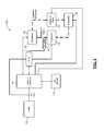
- FIG. 4is a schematic diagram of an example of a portion of a PFC circuit of the drive of FIG. 2 including a boost converter in accordance with an embodiment of the present disclosure.
- FIG. 5is an example plot of a rectified AC signal, a predetermined DC voltage and operational switch periods in accordance with an embodiment of the present disclosure.
- FIG. 6is an example plot of sensed current in the drive of FIG. 2 in accordance with an embodiment of the present disclosure.
- FIG. 7is a schematic diagram of an example electromagnetic interference (EMI) filter in accordance with an embodiment of the present disclosure.
- EMIelectromagnetic interference
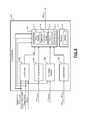
- FIG. 8is a functional block diagram of an example of a PFC switch control module in accordance with an embodiment of the present disclosure.
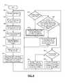
- FIG. 9is a flow diagram illustrating an example method of operating a drive with a PFC circuit having a boost converter in accordance with an embodiment of the present disclosure.
- FIG. 10is a schematic diagram of an example of a portion of a PFC circuit of a drive including a buck converter in accordance with an embodiment of the present disclosure.
- FIG. 11is a flow diagram illustrating an example method of operating a drive with a PFC circuit having a buck converter in accordance with an embodiment of the present disclosure.
- FIG. 12is a flow diagram illustrating an example method of operating a drive with a PFC circuit having a power converter in accordance with an embodiment of the present disclosure.
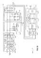
- FIG. 13is a schematic diagram of an example of a portion of a PFC circuit of the drive of FIG. 2 including a boost converter for a 3-phase implementation in accordance with an embodiment of the present disclosure.
- FIG. 14is a schematic diagram of another example of a portion of a PFC circuit of the drive of FIG. 2 including an inverter and a boost converter for a 3-phase implementation in accordance with an embodiment of the present disclosure.
- FIG. 15is a functional block diagram of an example of a 3-phase converter circuit including a non-line non-grounded EMI filter in a PFC circuit in accordance with an embodiment of the present disclosure.
- FIG. 16is a functional block and schematic diagram of an example of the 3-phase converter circuit of FIG. 15 .
- FIG. 17is a plot illustrating example 3-phase input voltages provided to the portion of FIG. 10 in accordance with an embodiment of the present disclosure.
- FIG. 18is a plot illustrating rectification and bus voltages overlaid on the 3-phase input voltages of FIG. 17 and for the portion of FIG. 10 in accordance with an embodiment of the present disclosure.
- FIG. 19is a plot illustrating rectification, choke, and bus voltages overlaid on the 3-phase input voltages of FIG. 17 and for the portion of FIG. 10 in accordance with another embodiment of the present disclosure.
- FIG. 20is schematic diagram of a synchronous rectifier in accordance with another embodiment of the present disclosure.
- FIG. 1is a functional block diagram of an example refrigeration system 100 including a compressor 102 , a condenser 104 , an expansion valve 106 , and an evaporator 108 .
- the refrigeration system 100may include additional and/or alternative components, such as a reversing valve or a filter-drier.
- the present disclosureis applicable to other types of refrigeration systems including, but not limited to, heating, ventilating, and air conditioning (HVAC), heat pump, refrigeration, and chiller systems.
- HVACheating, ventilating, and air conditioning
- the compressor 102receives refrigerant in vapor form and compresses the refrigerant.
- the compressor 102provides pressurized refrigerant in vapor form to the condenser 104 .
- the compressor 102includes an electric motor that drives a pump.
- the pump of the compressor 102may include a scroll compressor and/or a reciprocating compressor.
- the condenser 104transfers heat away from the refrigerant, thereby cooling the refrigerant.
- the refrigerant vaporis cooled to a temperature that is less than a saturation temperature, the refrigerant transforms into a liquid (or liquefied) refrigerant.
- the condenser 104may include an electric fan that increases the rate of heat transfer away from the refrigerant.
- the condenser 104provides the refrigerant to the evaporator 108 via the expansion valve 106 .
- the expansion valve 106controls the flow rate at which the refrigerant is supplied to the evaporator 108 .
- the expansion valve 106may include a thermostatic expansion valve or may be controlled electronically by, for example, a system controller 130 .
- a pressure drop caused by the expansion valve 106may cause a portion of the liquefied refrigerant to transform back into the vapor form. In this manner, the evaporator 108 may receive a mixture of refrigerant vapor and liquefied refrigerant.
- the refrigerantabsorbs heat in the evaporator 108 .
- Liquid refrigeranttransitions into vapor form when warmed to a temperature that is greater than the saturation temperature of the refrigerant.
- the evaporator 108may include an electric fan that increases the rate of heat transfer to the refrigerant.
- a utility 120provides power to the refrigeration system 100 .
- the utility 120may provide single-phase alternating current (AC) power at approximately 230 Volts root mean squared (V RMS ).
- the utility 120may provide three-phase AC power at approximately 400 V RMS , 480 V RMS , or 600 V RMS at a line frequency of, for example, 50 or 60 Hz.
- the three-phase AC poweris nominally 600 V RMS , the actual available voltage of the power may be 575 V RMS .
- the utility 120may provide the AC power to the system controller 130 via an AC line, which includes two or more conductors.
- the AC powermay also be provided to a drive 132 via the AC line.
- the system controller 130controls the refrigeration system 100 .
- the system controller 130may control the refrigeration system 100 based on user inputs and/or parameters measured by various sensors (not shown).
- the sensorsmay include pressure sensors, temperature sensors, current sensors, voltage sensors, etc.
- the sensorsmay also include feedback information from the drive control, such as motor currents or torque, over a serial data bus or other suitable data buses.
- a user interface 134provides user inputs to the system controller 130 .
- the user interface 134may additionally or alternatively provide the user inputs directly to the drive 132 .
- the user inputsmay include, for example, a desired temperature, requests regarding operation of a fan (e.g., a request for continuous operation of the evaporator fan), and/or other suitable inputs.
- the user interface 134may take the form of a thermostat, and some or all functions of the system controller (including, for example, actuating a heat source) may be incorporated into the thermostat.
- the system controller 130may control operation of the fan of the condenser 104 , the fan of the evaporator 108 , and the expansion valve 106 .
- the drive 132may control the compressor 102 based on commands from the system controller 130 .
- the system controller 130may instruct the drive 132 to operate the motor of the compressor 102 at a certain speed or to operate the compressor 102 at a certain capacity.
- the drive 132may also control the condenser fan.
- a thermistor 140is thermally coupled to the refrigerant line exiting the compressor 102 that conveys refrigerant vapor to the condenser 104 .
- the variable resistance of the thermistor 140therefore varies with the discharge line temperature (DLT) of the compressor 102 .
- the drive 132monitors the resistance of the thermistor 140 to determine the temperature of the refrigerant exiting the compressor 102 .
- the DLTmay be used to control the compressor 102 , such as by varying capacity of the compressor 102 , and may also be used to detect a fault. For example, if the DLT exceeds the threshold, the drive 132 may power down the compressor 102 to prevent damage to the compressor 102 .
- an example implementation of the drive 132includes an electromagnetic interference (EMI) filter and protection circuit 204 , which receives power from an AC line.
- the EMI filter and protection circuit 204reduces EMI that might otherwise be injected back onto the AC line from the drive 132 .
- the EMI filter and protection circuit 204may also remove or reduce EMI arriving from the AC line. Further, the EMI filter and protection circuit 204 protects against power surges, such as may be caused by lightening, and/or other other types of power surges and sags.
- a charging circuit 208controls power supplied from the EMI filter and protection circuit 204 to a power factor correction (PFC) circuit 212 .
- PFCpower factor correction
- the charging circuit 208may place a resistance in series between the EMI filter and protection circuit 204 and the PFC circuit 212 to reduce the amount of current inrush. These current or power spikes may cause various components to prematurely fail.
- the charging circuit 208may close a relay that bypasses the current-limiting resistor.
- a control module 220may provide a relay control signal to the relay within the charging circuit 208 .
- the control module 220may assert the relay control signal to bypass the current-limiting resistor after a predetermined period of time following start up, or based on closed loop feedback indicating that charging is near completion.
- the PFC circuit 212converts incoming AC power to DC power.
- the DC powermay have voltage ripples, which are reduced by filter capacitor 224 .
- Filter capacitor 224may include one or more capacitors arranged in parallel and connected to the DC bus.
- the PFC circuit 212may attempt to draw current from the AC line in a sinusoidal pattern that matches the sinusoidal pattern of the incoming voltage. As the sinusoids align, the power factor approaches one, which represents the greatest efficiency and the least demanding load on the AC line.
- the PFC circuit 212may include (i) one or more switches, (ii) a rectification circuit, and (iii) an AC choke or a DC choke depending on whether the choke is upstream or downstream of the rectification circuit.
- the PFC circuit 212includes one or more switches that are controlled by the control module 220 using one or more signals labeled as power switch control. The switches are controlled by the control module 220 using one or more signals labeled as power switch control.
- the control module 220determines the power switch control signals based on a measured voltage of the DC bus, measured current in the PFC circuit 212 , AC line voltages, temperature or temperatures of the PFC circuit 212 , and the measured state of a power switch in the PFC circuit 212 . While the example of use of measured values is provided, the control module 220 may determine the power switch control signals based on an estimated voltage of the DC bus, estimated current in the PFC circuit 212 , estimated AC line voltages, estimated temperature or temperatures of the PFC circuit 212 , and/or the estimated or expected state of a power switch in the PFC circuit 212 . In various implementations, the AC line voltages are measured or estimated subsequent to the EMI filter and protection circuit 204 but prior to the charging circuit 208 .
- the AC line voltagesare measured subsequent to the EMI filter and protection circuit 204 but prior to the charging circuit 208 .
- the PFC circuit 212if implemented as a passive PFC circuit may include a rectification circuit and an AC choke or a DC choke depending on whether the choke is upstream or downstream of the rectification circuit.
- the control module 220is powered by a DC-DC power supply 228 , which provides a voltage suitable for logic of the control module 220 , such as 3.3 Volts, 2.5 Volts, etc.
- the DC-DC power supply 228may also provide DC power for operating switches of the PFC circuit 212 and an inverter power circuit 232 .
- this voltagemay be a higher voltage than for digital logic, with 15 Volts being one example.
- the inverter power circuit 232also receives power switch control signals from the control module 220 . In response to the power switch control signals, switches within the inverter power circuit 232 cause current to flow in respective windings of a motor 236 of the compressor 102 .
- the control module 220may receive a measurement or estimate of motor current for each winding of the motor 236 or each leg of the inverter power circuit 232 .
- the control module 220may also receive a temperature indication from the inverter power circuit 232 .
- the temperature from the inverter power circuit 232 and the temperature from the PFC circuit 212are used only for fault purposes.
- a faultis declared and the drive 132 is either powered down or operated at a reduced capacity.
- the drive 132may be operated at a reduced capacity and if the temperature does not decrease at a predetermined rate, the drive 132 transitions to a shutdown state.
- the inverter power circuit 232may include one or more current sensors 259 for detecting current out of the inverter power circuit 232 and drawn by the motor 236 .
- the control module 220may also receive an indication of the discharge line temperature from the compressor 102 using the thermistor 140 .
- An isolation circuit 260may provide a pulse-width-modulated representation of the resistance of the thermistor 140 to the control module 220 .
- the isolation circuit 260may include galvanic isolation so that there is no electrical connection between the thermistor 140 and the control module 220 .
- the isolation circuit 260may further receive protection inputs indicating faults, such as a high pressure cutoff or a low pressure cutoff, where pressure refers to refrigerant pressure. If any of the protection inputs indicate a fault and, in some implementations, if any of the protection inputs become disconnected from the isolation circuit 260 , the isolation circuit 260 ceases sending the PWM temperature signal to the control module 220 . Therefore, the control module 220 may infer that a protection input has been received from an absence from the PWM signal. The control module 220 may, in response, shut down the drive 132 .
- protection inputsindicating faults, such as a high pressure cutoff or a low pressure cutoff, where pressure refers to refrigerant pressure.
- the control module 220controls an integrated display 264 , which may include a grid of LEDs and/or a single LED package, which may be a tri-color LED.
- the control module 220can provide status information, such as firmware versions, as well as error information using the integrated display 264 .
- the control module 220communicates with external devices, such as the system controller 130 in FIG. 1 , using a communications transceiver 268 .
- the communications transceiver 268may conform to the RS-485 or RS-232 serial bus standards or to the Controller Area Network (CAN) bus standard.
- CANController Area Network
- a PFC circuit 300is one implementation of the PFC circuit 212 of FIG. 2 .
- the PFC circuit 300includes a rectifier 304 that converts incoming AC into pulsating DC.
- the rectifier 304includes a full-wave diode bridge.
- the DC output of the rectifier 304is across first and second terminals.
- the first terminalis connected to an inductor 308 , while the second terminal is connected to a current sensor 312 .
- An opposite end of the inductor 308is connected to a node that is common to the inductor 308 , an anode of a diode 316 , and a first terminal of a switch 320 .
- the switch 320may include multiple switches and corresponding terminals
- the PFC circuit 300generates a DC bus, where a first terminal of the DC bus is connected to a cathode of the diode 316 while a second terminal of the DC bus is connected to the second output terminal of the rectifier 304 via the current sensor 312 .
- the current sensor 312can therefore sense the current within the switch 320 as well as the current in the DC bus and current in the inductor 308 .
- the second terminal of the DC busis also connected to a second terminal of the switch.
- a driver 324receives the power switch control signal from the control module 220 of FIG. 2 and rapidly charges or discharges a control terminal of the switch 320 .
- the switch 320may be a field effect transistor with a gate terminal as the control terminal.
- the driver 324in response to the power switch control signal, charges or discharges the capacitor at the gate of the field effect transistor.
- the switch 320may be a power metal-oxide-semiconductor field-effect transistor (MOSFET), such as the STW38N65M5 power MOSFET from STMicroelectronics.
- MOSFETpower metal-oxide-semiconductor field-effect transistor
- a switch monitor circuit 328measures whether the switch is on or off. This closed loop control enables the control module 220 to determine whether the switch 320 has reacted to a command provided by the power switch control signal and may also be used to determine how long it takes the switch 320 to respond to that control signal. The measured switch state is output from the switch monitor circuit 328 back to the control module 220 .
- the control module 220may update its control of the power switch control signal to compensate for delays in turning on and/or turning off the switch 320 .
- the inductor, the switch 320 , and the diode 316are arranged in a boost configuration.
- the switch 320closes, causing current through the inductor 308 to increase.
- the current through the inductor 308cannot change instantaneously because the voltage across an inductor is proportional to the derivative of the current.
- the voltage across the inductor 308becomes negative, meaning that the end of the inductor 308 connected to the anode of the diode 316 increases above the voltage output from the rectifier 304 .
- the current through the inductor 308can be fed through the diode 316 to the DC bus.
- the current through the inductor 308decreases and then the switch 320 is closed once more, causing the current and the inductor 308 to increase.
- the switch 320may be turned on until the current sensor 312 determines that a predetermined threshold of current has been exceeded. At that time, a switch 320 is turned off for a specified period of time. This specified period may be adaptive, changing along with the voltage of the DC bus as well as the voltage of the AC input change. However, the off time (when the switch 320 is open) is a specified value. Once a time equal to the specified value has elapsed, the switch 320 is turned back on again and the process repeats. The off time can be fixed or variable. In the case of the off time being variable, the off time can be limited to at least a predetermined minimum off time.
- the inductance of the inductor 308(which may be the largest contributor to physical size of the PFC circuit 300 ) may be lowered. However, with a lower inductance, the inductor 308 will saturate more quickly. Therefore, the switch 320 will have to operate more quickly. While more quickly and smaller are relative terms, present power switching control operates in the range of 10 kilohertz to 20 kilohertz switching frequencies. In the present application, the switching frequency of the switch 320 may be increased to more than 50 kilohertz, more than 100 kilohertz, or more than 200 kilohertz. For example, the switching frequency of the switch may be controlled to be approximately 200 kilohertz.
- the switch 320is therefore chosen to allow for faster switching as well as to have low switching losses. With faster switching, the inductance of the inductor 308 can be smaller. In addition, the diode 316 may need to be faster. Silicon carbide diodes may have fast response times. For example, the diode 316 may be a STPSC2006CW Silicon Carbide dual diode package from STMicroelectronics.
- control module 220may include multiple devices, such as a microprocessor configured to perform more involved calculations and an FPGA (field programmable gate array) or PLD (programmable logic device) configured to monitor and respond to inputs in near real time.
- a microprocessorconfigured to perform more involved calculations
- an FPGAfield programmable gate array
- PLDprogrammable logic device
- near real timemeans that the time resolution of measurement and delay in responding to inputs of the FPGA or PLD is negligible compared to the timeframes of interest.
- a bypass rectifier 340is connected in parallel with the rectifier 304 at the AC line input.
- a second output terminal of the bypass rectifier 340is connected to the second terminal rectifier 304 .
- a first output terminal of the bypass rectifier 340is connected to the cathode of the diode 316 .
- the bypass rectifier 340when the PFC circuit 300 is not operating to boost the DC bus voltage, the bypass rectifier 340 will be active when the line-to-line voltage of the AC input exceeds the voltage across the DC bus.
- the bypass rectifier 340diverts current from passing through the diode 316 . Because the inductor 308 is small, and the switch 320 switches rapidly, the diode 316 is selected to also exhibit fast switching times. The diode 316 may therefore be more sensitive to current, which is selectively shunted around the diode 316 by the bypass rectifier 340 .
- the current path through the rectifier 304 and the diode 316experiences three diode voltage drops or two diode voltage drops and the switch voltage drop, while the path through the bypass rectifier 340 experiences only two diode voltage drops.
- the single phase AC input in FIG. 3Ais associated with a boost converter topology
- the present disclosurealso encompasses a buck converter topology or a buck-boost converter topology.
- FIG. 3Ba buck converter topology is shown with a three-phase AC input signal. Note that the principles of the present disclosure also apply to a boost converter or buck-boost converter topology used with a three-phase AC input.
- a PFC circuit 350represents another implementation of the PFC circuit 212 of FIG. 2 .
- a three-phase rectifier 354receives three-phase AC and generates pulsating DC across first and second terminals.
- a switch 358is connected to the first terminal of the three-phase rectifier 354 by a current sensor 362 .
- the switch 358is connected to an inductor 366 at a common node.
- the common nodeis also connected to a cathode of a power diode 370 .
- An anode of the power diode 370is connected to a second terminal of the three-phase rectifier 354 .
- An opposite terminal of the inductor 366establishes one terminal of the DC bus, while the second output of the three-phase rectifier 354 establishes the other terminal of the DC bus.
- the switch 358 , the inductor 366 , and the diode 370are configured in a buck topology.
- the current sensor 362measures current through the inductor 366 as well as current through the DC bus.
- a driver 374drives a control terminal of the switch 358 based on a power switch control signal from the control module 220 in FIG. 2 .
- a switch monitor circuit 378detects whether the switch 358 has opened or closed and reports the switch state to the control module 220 . With the location of the current sensor 362 , the current sensor 362 will measure approximately zero current when the switch 358 is open.
- FIG. 4shows a portion 400 of the PFC circuit 212 of the drive 132 of FIG. 2 including a boost converter 401 .
- the portion 400 of FIG. 4includes a boost converter 401 and is configured for reception of a single phase AC signal, the portion may be implemented multiple times; once for each phase of a 3-phase input signal.
- the portion 400includes a rectification circuit 402 , an inductor 404 , a diode 406 , an EMI filter 407 , a switch 408 , a driver 410 and one or more current sensors 412 a , 412 b (collectively current sensors 412 ).
- the rectification circuit 402includes a primary (or first) bridge rectifier 414 and a secondary (or second) bridge rectifier 416 .
- the secondary bridge rectifier 416may be referred to as a bypass rectifier and allows for current to bypass the primary bridge rectifier 414 and the boost converter 401 .
- Each of the bridge rectifiers 414 , 416may include
- Each of the bridge rectifiers 414 , 416includes AC inputs, a return input and an output.
- the AC inputs of each of the bridge rectifiers 414 , 416are connected to a differential AC input 420 that receives an AC voltage V AC from the EMI filter 202 .
- the return inputsare connected to a same output 418 of the second current sensor 412 b .
- the output of the primary bridge rectifier 414is connected to an input of the first current sensor 412 a or the inductor 404 .
- the output of the secondary bridge rectifier 416is connected to a DC output 422 of the PFC circuit 212 .
- the output voltages of the bridge rectifiers 414 , 416may be referred to as main voltages.
- current sensors 412 a and 412 bare shown, other current sensors may be alternatively or additionally incorporated into the portion 400 .
- a current sensormay be connected in series with one or more of the diode 406 , the switch 408 , and the capacitor 430 . This current sensor may detect current passing through the diode 406 , the switch 408 and/or the capacitor 430 .
- the current sensoris connected between the inductor 404 and the switch 408 .
- the current sensoris connected between the switch 408 and the reference terminal 426 .
- any or all of the disclosed current sensorsmay be utilized. Any of the signals and/or parameters derived from the signals of the disclosed current sensors may be utilized in the below described circuits and methods.
- the EMI filter 407may be connected to the output of the primary bridge rectifier 414 or an output of the first current sensor 412 a .
- the EMI filter 407filters an output of the primary bridge rectifier 414 .
- the EMI filter 407decouples the boost converter 401 from the primary bridge rectifier 414 to minimize noise generated by the boost converter 401 from being seen at the primary bridge rectifier 414 .
- the DC output 422may be connected to the DC bus, which is connected between the PFC circuit 212 and the inverter power circuit 208 of FIG. 2 .
- the inductor 404 , diode 406 , switch 408 and driver 410provide the boost converter 401 , which increases a DC output voltage V DCOUT and/or a DC bus voltage of the DC bus to a commanded (or predetermined) DC voltage V DCCOM .
- the boost converter 401is a power converter.
- the commanded DC voltage V DCCOMmay be determined by the control module 250 and may be set to be less than a peak (or maximum) output voltage of the bridge rectifiers 414 , 416 .
- the inductor 404is connected in series with the diode 406 between (i) the output of the primary bridge rectifier 414 and/or the first current sensor 412 a and (ii) the DC output 422 .
- the inductor 404is connected (i) at a first end, to the output of the primary bridge rectifier 414 or the output of the first current sensor 412 , and (ii) at a second end, to an anode of the diode 406 and a first terminal of the switch 408 .
- the inductor 404may be small (e.g., 80 micro-Henry ( ⁇ H)) and operates as a choke.
- the diode 406may be formed of, for example, silicon carbide SiC for quick switching frequencies and no reverse recovery time.
- the diode 406may include multiple diodes connected in parallel.
- the switch 408may be a transistor, such as a super-junction field effect transistor (FET), a power metal oxide semiconductor field-effect transistor (MOSFET), and/or a super-junction MOSFET.
- the switch 408may be configured to be oscillated between ON (e.g., closed) and OFF (e.g., open) states at a high frequency (e.g., greater than or equal to 200 kilo-hertz (kHz)).
- the first terminal of the switch 408is connected to the inductor 404 and the anode of the diode 406 .
- a second terminal of the switch 408is connected to an input 425 of the second current sensor 412 b and a reference terminal 426 (e.g., a ground reference).
- a control terminal of the switch 408receives a control signal SW CTRL from the driver 410 .
- the driver 410generates the control signal SW CTRL based on an output signal PFC OUT of the control module 250 .
- the control module 250generates the output signal PFC OUT based on: one or more current sense signals PFC INC1 , PFC INC2 from the current sensors 412 a , 412 b ; an AC signal PFC ACREP representative of the AC voltage V AC ; and a DC signal PFC DCREP that is representative of the DC output voltage V DCOUT of the PFC circuit 212 .
- the current sense signal PFC INC1may be equal to and/or indicative of an amount of current (i) passing through the inductor 404 , and/or (ii) passing through the PFC circuit 212 .
- the current sense signal PFC INC2may be equal to and/or indicative of an amount of current (i) returning from the DC output 422 to the second current sensor 412 b , and/or (ii) passing through the PFC circuit 212 .
- the AC signal PFC ACREPmay be equal to and/or indicative of the AC voltage V AC .
- the DC signal PFC DCREPmay be equal to and/or indicative of the DC output voltage V DCOUT .
- a capacitor 430may be connected between the DC output 422 and the reference terminal 426 .
- the capacitor 430may be connected (i) at a first end, to a cathode of the diode 406 and to the DC output 422 , and (ii) at a second end, to the reference terminal 426 and the input 425 of the second current sensor 412 b.
- the boost convertermay be ON when the DC bus voltage is greater than the AC voltage V AC .
- Currentdoes not pass from the secondary rectifier 416 to the DC bus when the DC bus voltage is greater than the AC voltage V AC .
- the boost circuit 401may be active and storing energy in the inductor 404 and releasing energy from the inductor 404 onto the DC bus to boost voltage of the DC bus. The energy may be stored when the switch 408 is closed and released when the switch 408 is opened.
- FIG. 5shows a plot of a rectified AC signal 450 .
- the rectified AC signal 450may represent an output of the primary bridge rectifier 414 and/or an output of the secondary bridge rectifier 416 of FIG. 4 .
- the rectified AC signal 450may be offset from zero, such that a minimum voltage of the rectified AC signal 450 is at an offset voltage V Offset .
- the control module 250may control operation of the driver 410 to control a state of the switch 408 , such that the DC output voltage V DCOUT is equal to or within a predetermined range of the commanded DC voltage V DCCOM .
- the control module 250controls operation of the driver 410 , such that the switch 408 is oscillated between open and closed states at a predetermined frequency during active periods 452 and is maintained in an OFF (or open) state during inactive periods 454 .
- an output of the diode 406is provided to the DC output 422 while the switch 408 is in an open state and the DC output voltage V DCOUT is less than an output voltage of the primary bridge rectifier 414 .
- Thismay occur during the active periods 452 .
- voltages of the rectified AC signal 450are increased (i.e. boosted) to match the commanded DC voltage V DCCOM .
- An amount of time that the switch 408 is maintained in the OFF (or open) stateaffects how much a voltage of the rectified AC signal 450 is boosted to match the commanded DC voltage V DCCOM .
- the boost converter 401is ON during the active periods 452 . Conversely, the boost converter 401 is OFF during the inactive periods.
- the ON time and the OFF time of the switch 408 per AC cycle and thus the duty cycle of the switch 408is controlled by the control module 250 .
- the control module 250 and/or the driver 410may adjust the duty cycle of the switch 408 including adjusting the OFF time and/or the ON time of each pulse of the control signal SW CTRL . Operational control of the switch 408 is further described below.
- An output of the secondary bridge rectifier 416is provided to the DC output 422 when the DC output voltage V DCOUT is less than an output voltage of the primary bridge rectifier 416 , which may occur during (i) the active periods 452 when the switch 408 is being oscillated, and (ii) inactive periods 454 when the switch 408 is not being oscillated.
- the switch 408may be in an open state and the DC output voltage V DCOUT changes based on an output of the secondary bridge rectifier 416 .
- the diode 406is bypassed while the switch 408 is in the closed state.
- the DC output voltage V DCOUTmay increase from a voltage less than or equal to the commanded DC voltage V DCCOM to a voltage greater than or equal to the commanded DC voltage V DCCOM .
- the amount of increasemay depend on durations of the active periods and/or the inactive periods.
- start times s 1 -s 6 and end times e 1 -e 6 of active operation of the switch 408are shown.
- the switch 408is oscillated between ON and OFF states during the active periods 452 .
- the switch 408is not oscillated between ON and OFF states during the inactive periods 454 .
- start times s 1 -s 6 and end times e 1 -e 6are shown at certain angles (or phases) of the rectified AC signal 450 , the start times s 1 -s 6 and end times e 1 -e 6 may be adjusted in time relative to the rectified AC signal 450 .
- the end times e 1 -e 6correspond to moments in time when a voltage of the rectified AC signal 450 is increasing and matches the commanded DC voltage V DCCOM at a first (increasing) cross-over point.
- the start times s 1 -s 6correspond to moments in time when a voltage of the rectified AC signal 450 is decreasing and matches the commanded DC voltage V DCCOM at a second (decreasing) cross-over point.
- phase angles of V AC and/or outputs of the bridge rectifiers 414 , 416are described below with respect phase angles of V AC and/or outputs of the bridge rectifiers 414 , 416 .
- the implementations and corresponding conditions and taskmay be determined and/or performed, as described below, based on V AC , voltages of outputs of the bridge rectifiers 414 , 416 and/or voltages of an output of a corresponding power converter.
- the voltagesmay be monitored and used as an alternative to or in addition to the phase angles when performing the below described tasks.
- the end times e 1 -e 6may be adjusted to occur earlier in time and at phase angles of the rectified AC signal 450 prior to respective increasing cross-over points with the commanded DC voltage V DCCOM .
- the start times s 1 -s 6may be advanced to occur earlier in time and at phase angles of the rectified AC signal 450 prior to respective decreasing cross-over points with the commanded DC voltage V DCCOM and/or closer in time to the corresponding end times e 1 -e 6 . These adjustments may minimize how much the DC output voltage V DCOUT exceeds the commanded DC voltage V DCCOM and/or minimize peak current during the inactive periods.
- the inactive periodsare reduced in length, which decreases the amount of time that the output of the secondary bridge 416 is solely provided to the DC output 422 and/or decreases durations of the inactive periods.
- the secondary bridge rectifier 416protects the diode 406 from transient spikes in voltage out of the inductor 404 by allowing current to pass from the secondary bridge rectifier 416 directly to the DC output 422 .
- the secondary bridge rectifier 416minimizes the number of components between the differential AC input 420 and the DC output 422 .
- the frequency of oscillated operation of the switch 408is decreased rather than deactivated.
- the frequencymay be decreased to less than, for example, 200 kHz during low activity periods (or low activity mode). Timing of the low activity periods may be the same or similar to that of the previously described inactive periods. As an example, the frequency during the low activity periods may be an order of magnitude less than during the active periods (or active mode).
- operation of the switch 408may be transitioned between low activity modes and high activity modes rather than between inactive modes and active modes.
- the switch 408may be operated in the low activity mode during periods between the end points e 1 -e 6 and the successive start points s 1 -s 6 .
- the ON time (or closed periods) of the switch 408may be decreased for operation in the low activity mode and increased for operation in the high activity mode.
- start times s 1 -s 6are described with respect to start times of the active or high activity mode, the start times s 1 -s 6 also refer to end times of an inactive mode or low activity mode. Also, although the end times e 1 -e 6 are described with respect to end times of the active or high activity mode, the end times e 1 -e 6 also refer to start times of the inactive mode or low activity mode.
- the secondary bridge rectifier 416protects the diode 406 from spikes in voltage out of the inductor 404 .
- the secondary bridge rectifier 416minimizes number of components between the AC input 420 and the DC bus and/or DC output 422 .
- FIG. 6shows an example of changes in an amount of current sensed by the second current sensor 412 b of FIG. 4 due to the activation and deactivation of oscillated operation of the switch 408 .
- the oscillated operation of the switch 408is enabled at start times s 1 -s 6 and disabled at end times e 1 -e 6 , which correspond with the start times s 1 -s 6 and end times e 1 -e 6 of FIG. 5 .
- Lengths of increasing current periods 460 and decreasing current periods 462may be adjusted to change peaks of current 464 by altering the start times s 1 -s 6 and end times e 1 -e 6 , as described above.
- the peaks of current 464may be adjusted relative to a base peak current level Ibase.
- the above-described dual bridge circuit configurations of the bridge rectification circuit 402 of FIG. 4are able to handle an increased maximum allowable forward surge current (IFSM).
- the secondary bridge circuit 416is able to handle increased current over a single bypass diode arrangement, where the secondary bridge circuit 416 is replaced with two diodes instead of a full bridge. Arrangement provides higher efficiency if active PFC is not running.
- a single diodemay be used to replace the secondary bridge 416 by (i) connecting the anode of the single diode to the cathodes of the two diodes connected to the first current sensor 412 a , and (ii) a cathode of the diode to the output terminal 422 .
- the dual bridge circuit configurationsalso provide the conduction path for partial PFC operation when the peak of the input line voltage V AC is greater than V DCOUT .
- FIG. 7shows an example of the EMI filter 407 .
- the EMI filter 407may include one or more capacitors 470 . If more than one capacitor is included, the capacitors are connected in parallel between a first bus 472 and a second bus 474 .
- the first busis connected between the output of the bridge rectifier 414 and the inductor 404 .
- the second bus 474is connected between the second current sensor 412 b and the reference terminal 426 .
- FIG. 8shows the control module 250 that includes a load module 502 , an AC voltage module 504 , a DC voltage module 506 , a current module 508 , an output module 510 and a memory 512 .
- the modules 502 , 504 , 506 , 508 , 510 and the memory 512are shown as part of the control module 250 , one or more of the modules 502 , 504 , 506 , 508 , 510 and the memory 512 may be part of or also included in the system control module 270 .
- the information (data, parameters, and signals) received and/or generated by the module 502 , 504 , 506 , 508 , 510may be shared between the modules 502 , 504 , 506 , 508 , 510 .
- the output module 510may include a timing module 513 , a reference generation module 514 , timers 515 and/or a peak detector 517 .
- the memory 512may include one or more tables 516 . Operation of the modules 502 , 504 , 506 , 508 , 510 and memory 512 are described below with respect to the methods of FIGS. 9 and 11-12 .
- the output module 510may operate in the active mode, the inactive mode, the low activity mode, the high activity mode, a full PFC mode, and a partial PFC mode.
- the full PFC modemay refer to when the boosting converter 401 is continuously in an active or high activity mode to boost the DC bus voltage to match the commanded DC voltage V DCCOM . This may occur when the commanded DC voltage V DCCOM is greater than or equal to a peak voltage of the AC voltage V AC and/or outputs of the bridge rectifiers 414 , 416 .
- the partial PFC moderefers to switching between operating in (i) an active or high activity mode and (ii) an inactive or low activity mode.
- the timing module 513switches from operating in the full PFC mode to operating in the partial PFC mode.
- the partial PFC modereduces power losses by operating at reduced DC voltages and provides improved operating efficiency.
- the timing module 513may, for example, operate in the partial PFC mode during light compressor loading conditions (e.g., load on compressor less than a predetermined load) and operate in the full PFC mode during heavy compressor loading conditions (e.g., load on compressor greater than or equal to the predetermined load).
- the efficiencymay refer to a ratio between output power and input power of the boost converter 401 , the PFC circuit 212 and/or the drive 132 , which may be less than or equal to 1%.
- modules of FIGS. 2-4see below provided method of FIGS. 9 and 12 and below provided definition for the term “module”.
- FIGS. 9 and 11-12a method of operating a drive (e.g., the drive 132 of FIG. 2 ) with a boost converter (e.g., the boost converter 401 of FIG. 4 ) and a PFC circuit (e.g., the PFC circuit 212 of FIG. 2 ) is shown.
- a boost convertere.g., the boost converter 401 of FIG. 4
- a PFC circuite.g., the PFC circuit 212 of FIG. 2
- the tasksmay be iteratively performed. Tasks 602 - 614 may be performed while tasks 616 - 628 are performed.
- the methodmay begin at 600 .
- the load module 502may receive various signals and parameters from (i) the PFC circuit 212 of FIG. 2 including signals and parameters from the portion 400 of FIG. 4 , and (ii) the inverter power circuit 208 of FIG. 2 .
- the signals and parametersmay include a voltage DC VBUS of the DC bus between the PFC circuit 212 and the inverter power circuit 208 . At least some of the signals and parameters are disclosed in and described with respect to FIG. 2 .
- the signals and parametersmay include DC signals and/or measured DC voltages corresponding to DC voltages on the DC bus, amounts of current supplied to the compressor 102 , voltages of power supplied to the compressor 102 , sensor input data, commanded and/or manually entered parameters, and/or other shared data and parameters.
- the load module 502may generate a load signal LD that is indicative of a load on the compressor 102 based on the stated signals and parameters.
- the load signal LDmay be generated based on a load algorithm, one or more maps, one or more equations, one or more tables (e.g., one or more of the tables 516 ), predetermined (or historical) data, and/or predicted (or estimated) future data.
- the load algorithm, maps, equations and/or tablesmay relate the signals and parameters to provide a calculated load and/or value indicative of the load on the compressor.
- the AC voltage module 504may receive or generate the AC signal PFC ACREP .
- the AC voltage module 504may detect voltages at the outputs of the bridge rectifiers 414 , 416 .
- the AC signal PFC ACREPmay be set equal to and/or be representative of one or more of the outputs of the bridge rectifiers 414 , 416 .
- the DC voltage module 506may receive or generate the DC signal PFC DCREP .
- the DC voltage module 506may (i) detect the voltage DC VBUS at the DC bus between the PFC circuit 212 and the inverter power circuit 208 , and/or (ii) receive a DC bus voltage indication signal from a sensor and/or module external to the control module 250 and/or the DC voltage module 506 .
- the current module 508may determine an amount of current: supplied to the compressor 102 and/or passing through one or more of the current sensors 412 . This may be based on the current sense signals PFC INC1 , PFC INC2 .
- the reference generation module 514may generate a reference sinusoidal signal and/or a reference rectified sinusoidal signal.
- the references signalsmay be generated based on the AC input signal V AC , the outputs of the bridge rectifiers 414 , 416 , and/or an output of the EMI filter 407 .
- the reference signalsare generated based on the output of the EMI filter 407 . This may include estimating the phase of the output of the EMI filter 407 .
- the AC input signal V AC , the outputs of the bridge rectifiers 414 , 416 and/or the output of the EMI filter 407may have noise or irregular activity as not to be a perfect sinusoidal and/or rectified sinusoidal waves.
- the reference generation module 514generates the reference signals to be pure sinusoidal and/or rectified sinusoidal reference signals having the same phase as the AC input signal V AC , the outputs of the bridge rectifiers 414 , 416 and/or the output of the EMI filter 407 . This synchronizes the reference signals to the AC input signal V AC , the outputs of the bridge rectifiers 414 , 416 and/or the output of the EMI filter 407 .
- the reference generation module 514may output reference data signals including phase, frequency, period, and/or other time-varying derivative (or gradient) of the reference data signals.
- the reference datamay include scaled versions of the reference data signals.
- the timing module 513generates the commanded DC voltage V DCCOM to be less than a peak (or maximum) AC input voltage V AC and/or a peak (or maximum) output voltage of the bridge rectifiers 414 , 416 .
- the commanded DC voltage V DCCOMmay be set to be within a predetermined range of the peak output voltage of one or more of the bridge rectifiers 414 , 416 . As an example, as the load on the compressor 102 increases, the commanded DC voltage V DCCOM may be decreased.
- Mode transition pointsrefer to transitions between (i) the active (and/or high activity) mode (oscillated switch operation enabled) and (ii) the inactive mode (oscillated switch operation disabled) or low activity mode. Examples of mode transition points are shown as cross-over points in FIG. 5 , however the mode transition points may not match corresponding cross-over points depending on the start times and end times (i.e. phase angles and/or corresponding voltages) of the mode transition points.
- the timing module 513may adjust (i) next start times and/or end times of the oscillated operation of the switch 408 , (ii) duty cycle of the oscillated operation of the switch 408 , and/or (iii) frequency of the oscillated operation of the switch 408 . This may include adjusting times of rising and/or falling edges of the control signal SW CTRL .
- the stated adjustment(s)may be based on the load of the compressor determined at 602 , the AC voltage received and/or generated at 604 , the DC voltage received and/or generated at 606 , one or more of the current levels detected at 608 , and/or one or more of the reference signals generated at 610 .
- the adjustmentsmay also be based on capacitance of the DC bus, torque commanded of the compressor 102 , predicted voltages of the outputs of the bridge rectifiers 414 , 416 , and/or other parameters associated with operation of the portion 400 .
- the adjustmentsmay advance or delay the transition start times and/or the transition end times.
- the adjustmentsmay be determined based on equations, algorithms, maps, and/or tables relating the stated parameters, which may be stored in the memory 512 and accessed by the timing module 513 .
- the adjustmentsmay also be based on previous (historical) values and/or results, which may be stored in and accessed from the memory 512 .
- next transition end time or transition start timemay be advanced to reduce the peak DC bus voltage or peak detected current.
- the timing module 513determines whether the phase angle of the output of one or more of the bridge rectifiers 414 , 416 matches a predetermined start time of an active period.
- voltages of the outputs of the bridge rectifiers 414 , 416 (or input of the inductor 404 ) and/or the output of the boost converter 401 (or output of the diode 406 )may be compared to predetermined voltages for the predetermined start time to determine whether the stated condition exists. If there is a match, task 618 is performed, otherwise task 620 is performed.
- the timing module 513transitions to the active (or high activity) mode. This includes oscillated operation of the switch 408 at a first (or high) frequency.
- the duty cycle of the switch 408including durations of ON times and OFF times, may correspond to duty cycle information determined at 614 .
- Task 602may be performed subsequent to task 618 .
- the timing module 513may determine whether the DC bus voltage is less than or equal to the commanded DC voltage V DCCOM and/or whether a next transition phase angle (next phase angle at which point a transition between operating modes occurs) is an end time (e.g., one of the end times e 1 -e 6 of FIGS. 5-6 ) for an active mode and/or high activity mode.
- a next transition phase anglee.g., one of the end times e 1 -e 6 of FIGS. 5-6
- voltages of the outputs of the bridge rectifiers 414 , 416 and/or the boost converter 401may be compared to predetermined voltages for the end time to determine whether one or more of the stated conditions exist.
- the timing module 513may also or alternatively determine whether the current transition phase angle is within a predetermined phase angle range (e.g., between a last start time and a subsequent end time) of a current active mode and/or high activity mode. In addition or alternatively, voltages of the outputs of the bridge rectifiers 414 , 416 and/or the boost converter 401 may be compared to a predetermined voltage ranges corresponding to the predetermined phase angle range to determine whether the stated condition exists. At the end time, the timing module 513 transitions from an active and/or high activity mode to an inactive or low activity mode. If the DC bus voltage is less than or equal to the commanded DC voltage V DCCOM and/or the next transition phase angle is at an end time for an active mode and/or high activity mode, then task 622 is performed, otherwise task 624 is performed.
- a predetermined phase angle rangee.g., between a last start time and a subsequent end time
- the timing module 513operates in the active mode and/or high activity mode. Task 602 may be performed subsequent to task 622 .
- the timing module 513determines whether the phase angle is an end time of an active mode and/or a high activity mode. In addition or alternatively, voltages of the outputs of the bridge rectifiers 414 , 416 and/or the boost converter 401 may be compared to predetermined voltages for the end time to determine whether the stated condition exists. If the phase angle is an end time, task 626 is performed, otherwise task 628 is performed. At 626 , the timing module 513 transitions to the inactive mode or low activity mode.
- the boost converter 401is transitioned to an OFF state and the switch 408 is switched to a closed state.
- Thisallows for pure rectification via the secondary bridge rectifier 416 .
- the output of the secondary bridge rectifier 416is provided to the DC output 422 without receiving current from the primary bridge rectifier 414 , the inductor 404 and the diode 406 .
- the pure rectificationreduces voltage and power losses.
- the timing module 513transitions to the low activity mode, then oscillated operation of the switch 408 continues, but at a reduced frequency and/or at an increased duty cycle, such that OFF times of the switch 408 are increased and/or the ON times of the switch 408 are decreased.
- Task 602may be performed subsequent to task 626 .
- the timing module 513remains in the inactive mode or operating in the low activity mode.
- Task 602may be performed subsequent to task 628 .
- tasks 616 - 628may be performed in a different order.
- task 624 , 626 , 628may be performed prior to tasks 616 , 618 , 620 and 622 .
- task 620may be modified to determine whether the DC bus voltage is greater than or equal to the commanded voltage, the next transition phase angle is a start time of an inactive mode or low activity mode, and/or the current phase angle is within a predetermined range (e.g., between an end time of an active mode and/or high activity mode and a subsequent start time of the active mode and/or high activity mode).
- Thismay include comparing voltages of the outputs of the bridge rectifiers 414 , 416 and/or the boost converter 401 to corresponding predetermined voltages and ranges to effectively determine if the next transition phase angle is a start time of an inactive mode or low activity mode, and/or the current phase angle is within a predetermined range.
- FIG. 10is a schematic diagram of a portion 700 of a PFC circuit (e.g., the PFC circuit 212 of FIG. 2 ) of a drive (e.g., the drive 132 of FIG. 1 ) including a buck converter 701 .
- the portion 700includes a rectification circuit 702 , an inductor 704 , a diode 706 , an EMI filter 707 , a switch 708 , a driver 710 and one or more current sensors 712 a , 712 b .
- the rectification circuit 702includes a bridge rectifier 714 .
- the bridge rectifier 714may include six diodes, as shown.
- the bridge rectifier 714includes AC inputs, a return input and an output.
- the AC inputs of the bridge rectifier 714receive a 3-phase AC voltage V AC from a 3-phase AC input 720 .
- the return inputsare connected to a same output 718 of the second current sensor 712 b .
- the output of the bridge rectifier 714is connected to the switch 708 .
- An output voltage of the bridge rectifier 714may be referred to as a main voltage.
- the EMI filter 707may be connected to the output of the bridge rectifier 714 or an output of the first current sensor 712 a .
- the EMI filter 707filters output of the bridge rectifier 714 .
- the EMI filter 707decouples the buck converter 701 from the bridge rectifier 714 to minimize noise generated by the buck converter 701 from being seen at the bridge rectifier 714 .
- An example EMI filter that may replace the EMI filter 707is shown in FIG. 7 .
- the DC output 722may be connected to an input of the DC bus, which is connected between the PFC circuit 212 and the inverter power circuit 208 of FIG. 2 .
- the inductor 704 , diode 706 , switch 708 and driver 710provide the buck converter 701 .
- the buck converter 701operates as a power converter.
- the buck converter 701instead of boosting voltage as does the boost converter 401 of FIG. 4 , steps down voltage while stepping up current.
- the buck converter 701may be (i) OFF (operating in an inactive mode and switch 708 is held in an open state) or ON and switching the switch 708 between ON and OFF states at a low frequency for rising and falling portions of rectified AC signal out of the bridge rectifier 714 , or (ii) ON and switching the switch 708 between ON and OFF states at a high frequency near peaks of the rectified AC signal out of the bridge rectifier 714 .
- the operation of the buck converter 701limits the DC output voltage V DCOUT at the DC output terminal 722 while reducing power losses of the buck converter 701 .
- the timing module 513 of FIG. 8may command a DC output voltage V DCOUT and/or DC bus voltage (first predetermined voltage) that are greater than a peak voltage of the input voltage V AC , the output of the bridge rectifier 714 , and/or during rising and falling portions of the rectified AC signal out of the bridge rectifier 714 .
- the timing module 513may command a DC output voltage V DCOUT and/or a DC bus voltage (second predetermined voltage) that are less than the peak voltage of the input voltage V AC and/or the output of the bridge rectifier 714 during a period when the DC output voltage V DCOUT and/or the DC bus voltage are within a predetermined range.
- the predetermined rangemay be centered on the peak voltage of the input voltage V AC and/or the output of the bridge rectifier 714 .
- the commanded voltagesmay be determined by the control module 250 .
- the inductor 704is connected (i) at a first end, to the switch and a cathode of the diode 706 , and (ii) at a second end, to the DC output terminal 722 and a capacitor 723 .
- the inductor 704operates as a choke and may be small (e.g., 80 micro-Henry ( ⁇ H)).
- the diode 706may be formed of, for example, silicon carbide SiC.
- the anode of the diode 706is connected to an input 724 of the second current sensor 712 b and a reference terminal 726 (e.g., a ground reference).
- the switch 708is connected in series with the inductor 704 between (i) the output of the primary bridge rectifier 714 and/or the first current sensor 712 a and (ii) the inductor 704 .
- the switch 708may be a transistor, such as a super-junction field effect transistor (FET), a power metal oxide semiconductor field-effect transistor (MOSFET), and/or a super-junction MOSFET.
- the switch 708may be configured to be oscillated between ON (e.g., closed) and OFF (e.g., open) states at a high frequency (e.g., greater than or equal to 200 kilo-hertz (kHz)).
- a first terminal of the switch 708is connected to the output of the primary bridge rectifier 714 or an output of the first current sensor 712 a .
- a second terminal of the switch 708is connected to the inductor 704 and a cathode of the diode 706 .
- a control terminal of the switch 708receives a control signal SW CTRL from the switch driving (or control) circuit 710 .
- the driver 710generates the control signal SW CTRL based on an output signal PFC OUT of the control module 250 .
- the control module 250generates the output signal PFC OUT based on: one or more current sense signal PFC INC1 , PFC INC2 from the current sensors 712 ; an AC signal PFC ACREP representative of the AC voltage V AC ; and a DC signal PFC DCREP that is representative of the DC output voltage V DCOUT of the PFC circuit 212 .
- the current sense signal PFC INC1may be equal to and/or indicative of an amount of current (i) passing through the inductor 704 , and/or (ii) passing through the PFC circuit 212 .
- the current sense signal PFC INC2may be equal to and/or indicative of an amount of current (i) returning from the DC output 722 to the second current sensor 712 b , and/or (ii) passing through the PFC circuit 212 .
- the AC signal PFC ACREPmay be equal to and/or indicative of the AC voltage V AC .
- the DC signal PFC DCREPmay be equal to and/or indicative of the DC output voltage V DCOUT .
- the capacitor 723may be connected between the DC output 722 and the reference terminal 726 .
- the capacitor 723may be connected (i) at a first end, to the inductor 704 and the DC output terminal 722 , and (ii) at a second end, to the input 724 of the second current sensor 712 b and the reference terminal 726 .
- the buck converter 701may be turned ON (i.e. the switch 708 is closed) and is maintained in the ON state, such that there is no switching loses. This may occur during light load conditions.
- the buck converter 701includes a bypass relay 730 that is connected across the switch 708 and is controlled by the control module 250 .
- the bypass relay 730may be ON (i.e. conducting) and the switch 708 may be OFF (or OPEN) when V AC and/or Vbridge (voltage out of rectification circuit 702 ) is less than a maximum allowable predetermined voltage (e.g., a maximum voltage that can be applied to the corresponding power module and/or received by the portion 700 ) and/or when the level of current out of the inverter power circuit 232 is less than a predetermined maximum level of current.
- the bypass relay 730may be OFF (i.e.
- the switch 708may be ON (or CLOSED) or pulse width modulated when V AC and/or Vbridge is greater than or equal to the maximum allowable predetermined voltage and/or when the level of current out of the inverter power circuit 232 is greater than or equal the predetermined maximum level of current.
- peak current mode control or average current mode controlmay be performed when the switch 708 is ON or pulse width modulated. This may include adjusting the duty cycle and/or frequency of the SW CTRL .
- the stated operation of the bypass relay 730 and switch 708may be performed as described below with respect to FIGS. 17-18 for the first partial buck mode.
- FIG. 11shows a method of operating a drive (e.g., the drive 132 of FIG. 2 ) with a buck converter (e.g., the buck converter 701 ) and a PFC circuit (e.g., the PFC circuit 212 of FIG. 2 ) is shown.
- a drivee.g., the drive 132 of FIG. 2
- a buck convertere.g., the buck converter 701
- a PFC circuite.g., the PFC circuit 212 of FIG. 2
- the methodmay begin at 800 .
- the load module 502may receive various signals and parameters from (i) the PFC circuit 212 of FIG. 2 including signals and parameters from the portion 700 of FIG. 10 , and (ii) the inverter power circuit 208 of FIG. 2 .
- the signals and parametersmay include a voltage DC VBUS of the DC bus between the PFC circuit 212 and the inverter power circuit 208 . At least some of the signals and parameters are disclosed in and described with respect to FIG. 2 .
- the signals and parametersmay include DC signals and/or measured DC voltages corresponding to DC voltages on the DC bus, amounts of current supplied to the compressor 102 , voltages of power supplied to the compressor 102 , sensor input data, commanded and/or manually entered parameters, and/or other shared data and parameters.
- the load module 502may generate a load signal LD that is indicative of a load on the compressor 102 based on the stated signals and parameters.
- the load signal LDmay be generated based on a load algorithm, one or more maps, one or more equations, one or more tables (e.g., one or more of the tables 516 ), predetermined (or historical) data, and/or predicted (or estimated) future data.
- the load algorithm, maps, equations and/or tablesmay relate the signals and parameters to provide a calculated load and/or value indicative of the load on the compressor.
- the AC voltage module 504may receive or generate the AC signal PFC ACREP .
- the AC voltage module 504may detect voltages at the output of the bridge rectifier 714 .
- the AC signal PFC ACREPmay be set equal to and/or be representative of one or more of the output of the bridge rectifier 714 .
- the DC voltage module 506may receive or generate the DC signal PFC DCREP .
- the DC voltage module 506may (i) detect the voltage DC VBUS at the DC bus between the PFC circuit 212 and the inverter power circuit 208 , and/or (ii) receive a DC bus voltage indication signal from a sensor and/or module external to the control module 250 and/or the DC voltage module 506 .
- the current module 508may determine an amount of current: supplied to the compressor 102 and/or passing through one or more of the current sensors 712 . This may be based on the current sense signals PFC INC1 , PFC INC2 .
- the reference generation module 514may generate a reference sinusoidal signal and/or a reference rectified sinusoidal signal.
- the references signalsmay be generated based on the AC input signal V AC , the output of the bridge rectifier 714 , and/or an output of the EMI filter 707 .
- the reference signalsare generated based on the output of the EMI filter 707 . This may include estimating the phase of the output of the EMI filter 707 .
- the AC input signal V AC , the output of the bridge rectifier 714 and/or the output of the EMI filter 707may have noise or irregular activity as not to be perfect sinusoidal and/or rectified sinusoidal waves.
- the reference generation module 514generates the reference signals to be pure sinusoidal and/or rectified sinusoidal reference signals having the same phase as the AC input signal V AC , the output of the bridge rectifier 714 and/or the output of the EMI filter 707 . This synchronizes the reference signals to the AC input signal V AC , the output of the bridge rectifier 714 and/or the output of the EMI filter 707 .
- the reference generation module 514may output reference data including phase, frequency, period, and/or other time-varying derivative (or gradient) of the reference signals.
- the reference datamay include scaled versions of the reference signals.
- the timing module 513generates the commanded DC voltage V DCCOM to be less than a peak (or maximum) AC input voltage V AC and/or a peak (or maximum) output voltage of the bridge rectifier 714 .
- the commanded DC voltage V DCCOMmay be set to be within a predetermined range of the peak output voltage of the bridge rectifier 714 .
- the commanded DC voltage V DCCOMmay be decreased.
- Mode transition pointsrefer to transitions between (i) the active (and/or high activity) mode (oscillated switch operation enabled) and (ii) the inactive mode (oscillated switch operation disabled) or low activity mode. Examples of mode transition points are shown as cross-over points in FIG. 5 , however the mode transition points may not match corresponding cross-over points depending on the start times and end times (i.e. phase angles) of the mode transition points.
- mode transition pointsby increasing the commanded DC voltage V DCCOM relative to the peak voltage of V AC and/or output of the bridge rectifier 714 , periods when oscillated operation of the switch 708 are decreased in length. A small change in the commanded DC voltage V DCCOM can make a large difference in peak current supplied.
- the timing module 513may adjust (i) next start times and/or end times of the oscillated operation of the switch 708 , (ii) duty cycle of the oscillated operation of the switch 708 , and/or (iii) frequency of the oscillated operation of the switch 708 . This may include adjusting times of rising and/or falling edges of the control signal SW CTRL .
- the stated adjustment(s)may be based on the load of the compressor determined at 802 , the AC voltage received and/or generated at 804 , the DC voltage received and/or generated at 606 , one or more of the current levels detected at 808 , and/or one or more of the reference signals generated at 810 .
- the adjustmentsmay also be based on capacitance of the DC bus, torque commanded of the compressor 102 , predicted voltages of the output of the bridge rectifier 714 , and/or other parameters associated with operation of the portion 700 .
- the adjustmentsmay advance or delay the transition start times and/or the transition end times.
- the adjustmentsmay be determined based on equations, algorithms, maps, and/or tables relating the stated parameters, which may be stored in the memory 512 and accessed by the timing module 513 .
- the adjustmentsmay also be based on previous (historical) values and/or results, which may also be stored in and accessed from the memory 512 .
- next transition end time or transition start timemay be advanced to reduce the peak DC bus voltage and/or peak detected current.
- the timing module 513determines whether the phase angle of the output of the bridge rectifier 714 matches a predetermined start time of an active period.
- voltages of the output of the bridge rectifier 714 (or input to switch 708 ) and/or the output of the buck converter 701 (or output of the inductor 704 )may be compared to predetermined voltages for the predetermined start time to determine whether the stated condition exists. If there is a match, task 818 is performed, otherwise task 620 is performed.
- the timing module 513transitions to the inactive mode or low activity mode. If the timing module 513 transitions to the inactive mode, then the buck converter 701 is transitioned to an OFF state and the switch 408 is switched to an open state. If the timing module 513 transitions to the low activity mode, then oscillated operation of the switch 708 continues, but at a reduced frequency and/or at a reduced duty cycle, such that OFF times of the switch 708 are increased and/or ON times of the switch 708 are decreased. Task 802 may be performed subsequent to task 818 .
- the timing module 513may determine whether the DC bus voltage is less than or equal to the commanded DC voltage V DCCOM and/or whether a next transition phase angle (next phase angle at which point a transition between operating modes occurs) is an end time (e.g., one of the end times e 1 -e 6 of FIGS. 5-6 ) for an inactive mode and/or low activity mode.
- a next transition phase angle(next phase angle at which point a transition between operating modes occurs) is an end time (e.g., one of the end times e 1 -e 6 of FIGS. 5-6 ) for an inactive mode and/or low activity mode.
- voltages of the output of the bridge rectifier 714 and/or the buck converter 701may be compared to predetermined voltages for the predetermined end time to determine whether one or more of the stated conditions exist.
- the timing module 513may also or alternatively determine whether the current transition phase angle is within a predetermined range (e.g., between a last start time and a subsequent end time) of a current inactive mode or low activity mode. In addition or alternatively, voltages of the output of the bridge rectifier 714 and/or the buck converter 701 may be compared to predetermined voltages for the predetermined range to determine whether the stated condition exists. At the end time, the timing module 513 transitions from an inactive mode or low activity mode to an active and/or high activity mode. If the DC bus voltage is less than or equal to the commanded DC voltage V DCCOM and/or the next transition phase angle is at an end time for an inactive mode or low activity mode, then task 822 is performed, otherwise task 821 is performed.
- a predetermined rangee.g., between a last start time and a subsequent end time
- voltages of the output of the bridge rectifier 714 and/or the buck converter 701may be compared to predetermined voltages for the predetermined range to
- the timing module 513determines whether (i) a light load condition exists, (ii) V AC is less than a “high-line” voltage (is at or near a maximum operating voltage) and/or voltage out of the bridge 714 (or Vbridge) is less than a predetermined maximum voltage, and/or (iii) if temperature of the inverter power circuit 232 is inbound (i.e. within a predetermined temperature range).
- V ACis less than the “high-line” voltage and/or output of the bridge 714 Vbridge is less than the predetermined maximum voltage
- V ACis less than a “high-line” voltage
- Vbridgeis less than a predetermined maximum voltage
- the temperature of the inverter power circuit 232is inbound
- task 830is performed, otherwise task 824 is performed.
- the timing module 513remains in the inactive mode or operating in the low activity mode. Task 802 may be performed subsequent to task 822 .
- the timing module 513determines whether the phase angle is an end time of an active mode and/or a high activity mode. In addition or alternatively, a voltage of the output of the bridge rectifier 714 and/or the buck converter 701 may be compared to predetermined voltages for the end time to determine whether the stated condition exists. If the phase angle is an end time, task 826 is performed, otherwise task 828 is performed.
- the timing module 513transitions to the active (or high activity) mode. This includes oscillated operation of the switch 708 at a first (or high) frequency.
- the duty cycle of the switch 808may correspond to duty cycle information determined at 814 .
- Task 802may be performed subsequent to task 826 .
- the timing module 513operates in the active mode or high activity mode. Task 802 may be performed subsequent to task 828 .
- the switch 708is held in a closed (or ON) state and is not switched between states.
- the portion 700performs as a 3-phase rectifier with a DC choke.
- no switchingoccurs when V AC is at a nominal or low-line voltage.
- Task 802may be performed subsequent to task 830 .
- V ACis too high (e.g., greater than predetermined voltage)
- switching of the switch 708occurs to decrease the bus voltage V DCOUT .
- the control module 250begins bucking by pulse width modulating the switch 708 to lower the bus voltage V DCOUT (e.g., at tasks 826 , 828 ) to a selected command voltage.
- the control module 250may shape the current by adjusting the duty cycle of SW CTRL during this period for PFC operation. This may include providing a flat (or constant) amount of current through the choke or a profiled current shape.
- Partial buckThe ability to buck during certain conditions and not to buck during other conditions.
- the switch 708is left ON since the amount of current through the inductor 704 is low. As the current through the inductor 704 increases for increased load, the switch may be pulse width modulated to decrease the bus voltage. This prevents overheating the inverter power circuit 232 of FIG. 2 during heavy load conditions.
- tasks 816 - 830may be performed in a different order.
- task 821 , 824 , 826 , 828may be performed prior to tasks 816 , 818 , 820 and 822 .
- task 820may be modified to determine whether the DC bus voltage is greater than or equal to the commanded voltage, the next transition phase angle is a start time of an active mode and/or high activity mode, and/or the current phase angle is within a predetermined range (e.g., between an end time of an inactive mode or a low activity mode and a subsequent start time of the inactive mode or low activity mode).
- Thismay include comparing a voltage of the outputs of the bridge rectifier 714 and/or the buck converter 701 to corresponding predetermined voltages and ranges to effectively determine if the next transition phase angle is a start time of an active mode and/or high activity mode, and/or the current phase angle is within a predetermined range.
- FIGS. 9 and 11are meant to be illustrative examples; the tasks may be performed sequentially, synchronously, simultaneously, continuously, during overlapping time periods or in a different order depending upon the application. Also, any of the tasks may not be performed or skipped depending on the implementation and/or sequence of events.
- Peak mode controlrefers to operating mode transition control near peak DC bus voltages and controls peak voltages of the DC bus voltages. This is because of high speed switch control and transitioning between operating modes based on transition phase angles.
- the transitioning phase anglesare determined based on a generated reference sinusoidal signal.
- the transition phase anglesare not determined based only on an AC input and/or an output of a bridge rectifier, but rather are determined based on both (i) an AC input and/or the output of the bridge rectifier, and (ii) the reference sinusoidal signal.
- This high speed controlis provided with feedback control based on various parameters feedback to the control module 250 , as described above.
- voltage thresholds and/or current thresholdsmay be adjusted, monitored and/or used as a basis for transitioning between operating modes.
- the voltage DC VBUS of the DC busmay be monitored and when the voltage DC VBUS exceeds or drops below voltage thresholds, the timing module 513 of FIG. 8 may transition between (i) the active mode and/or high activity mode and (ii) the inactive or low activity mode.
- the voltage thresholdsmay correspond to the transition phase angles of the rectified AC signals out of one or more of the bridge rectifiers of the PFC circuit 212 .
- the method of FIG. 12may be performed to adjust transition timing between operating modes (the active mode, the high activity mode, the inactive mode, and/or the low activity mode).
- the method of FIG. 12may be performed to maintain current levels detected by the current sensors 412 between predetermined operating ranges.
- the method of FIG. 12may also be performed to adjust the DC bus voltage to be within a predetermined range for partial PFC operation.
- FIG. 12a method of operating a drive (e.g., the drive 132 of FIG. 2 ) with a power converter (e.g., the boost converter 401 of FIG. 4 ) and a PFC circuit (e.g., the PFC circuit 212 of FIG. 2 ) is shown.
- a power convertere.g., the boost converter 401 of FIG. 4
- a PFC circuite.g., the PFC circuit 212 of FIG. 2
- the tasksmay be easily modified to apply to other implementations of the present disclosure.
- the tasksmay be modified to apply to the buck converter 701 of FIG. 10 .
- the tasksmay be iteratively performed. Tasks 908 - 920 may be performed while tasks 922 - 940 are performed.
- the methodmay begin at 900 , which may include resetting the timers 515 of FIG. 8 .
- the modules 502 , 504 , 506 , 508may receive and/or determine various signals and/or parameters, such as the signals received and determined during tasks 602 - 608 of FIG. 9 .
- the parametersinclude a measured DC bus voltage, a speed of a compressor, an amount of load, and/or an amount of current drawn by the compressor and/or detected by one or more of the current sensors 412 .
- the output module 510may determine whether a first timer (one of timers 515 ) is indicative that a first predetermined period has been reached (e.g., 100 ms).
- the first predetermined periodmay be set to provide stability. If the first predetermined period (or amount of time) has passed, task 912 is performed, otherwise task 910 may be performed.
- the first timermay be incremented, if implemented as a counter. Task 902 may be performed subsequent to tasks 908 and/or 910 .
- the first timermay be reset.
- the output module 510determines whether a peak current Ipeak and/or measured current level is greater than a first predetermined maximum current level Ipredmax 1 (e.g., 20 A). Task 914 may be performed to determine if partial PFC has been performed too long, such that the peak current Ipeak is high and should be decreased to be within a predetermined range (e.g., between 15 A and 20 A).
- the peak current Ipeakmay be, for example, current detected by the second current sensor 412 b or indicated by PFC INC2 . If the peak current Ipeak is greater than the first predetermined maximum current level Ipredmax 1 , then task 916 is performed, otherwise task 918 is performed.
- the output module 510sets an adjustment variable Adjust equal to Adjust minus a predetermined amount (e.g., 2V).
- the adjustment variable Adjustis used to adjust a commanded DC voltage V DCCOM at 940 . For example, if commanded DC voltage V DCCOM is increased, then less partial PFC operation. If commanded DC voltage V DCCOM is decreased, then more (or longer) partial PFC operation is performed. Task 902 may be performed after task 916 .
- the output module 510determines whether Ipeak and/or measured current level is less than a predetermined minimum current level Ipredmin (e.g., 15 A). Task 918 may be performed to determine if Ipeak is low and partial PFC operation can be performed longer to increase Ipeak to be within the predetermined range.
- the current detected by the current sensors 412may be low and gradually increase. As an example, the current detected by the current sensor 412 b may gradually increase to be between Ipredmin and Ipredmax 1 . If Ipeak and/or measured current level is less than Ipredmin, then task 920 is performed, otherwise task 902 is performed. At 920 , Adjust is set equal to Adjust plus a predetermined amount (e.g., 2V).
- the output module 510determines whether a second timer (another one of the timers 515 ) is indicative of a second predetermined period (e.g., 1 ms) being reached.
- the second predetermined periodmay be less than the first predetermined period and may be set to allow detection of quick changes in current and/or voltage. If the second predetermined period (or amount of time) has passed, task 924 is performed, otherwise task 923 may be performed.
- the second timermay be incremented, if implemented as a counter. Task 902 may be performed subsequent to tasks 922 and/or 923 .
- the second timermay be reset.
- control module 250determines whether power factor correction is disabled. If power factor correction is disabled, task 926 is performed, otherwise task 927 is performed. At 926 , the output module 510 sets Adjust equal to 0 and V DCCOM equal to 0.
- the output module 510may (i) determine initial values for a requested voltage Vreq (e.g., 280V) and a temporary voltage Vtmp if the corresponding drive 132 is powered up, or (ii) adjust and/or maintain current values of Vreq and Vtmp if performing an additional iteration of the method of FIG. 12 .
- the requested voltage Vreqmay refer to a minimum voltage requested for operation of the compressor 102 .
- the temporary voltage Vtmpmay be set equal to a peak voltage Vpeak (e.g., 325V) plus an offset voltage (e.g., 10V). Vtmp may be initially set high, such that there are not any current peaks, such as peaks 464 of FIG.
- the current peakis Ibase.
- the peak voltage Vpeakis a peak AC V AC input voltage or peak voltage out of the bridge rectifiers 414 , 416 .
- the requested voltage Vreqmay be determined based on the signals and/or parameters received, generated and/or determined during task 902 .
- the requested voltage Vreqmay be based on a speed of a motor of the compressor 102 and/or other operating conditions (e.g., load on the compressor 102 ).
- the requested voltage Vreqmay be determined based on an algorithm, a map, a table, and/or equations. As an example, the table may relate speeds of the motor of the compressor 102 to requested voltages.
- the output module 510determines whether Vreq is greater than or equal to Vtmp. If Vreq is greater than or equal to Vtmp, then task 930 is performed, otherwise task 932 is performed. If Vreq is greater than or equal to Vtmp and the power converter is a boost converter, then the boost converter may be operated to continuously boost the DC bus voltage. At 930 , the output module 510 sets Adjust equal to 0 and V DCCOM equal to Vreq.
- the output module 510determines whether (i) Ipeak and/or measured current level is greater than a second predetermined maximum current level Ipredmax 2 (e.g., 25 A), and/or (ii) Adjust is less than 0. Ipredmax 2 is greater than Ipredmax 1 .
- This taskdetermines whether the current detected by one of the current sensors 412 is too high, which may occur when load on the compressor 102 increases. If Ipeak and/or measured current level is greater than Ipredmax 2 and/or Adjust is less than 0, then task 934 is performed, otherwise task 936 is performed. Performance of tasks 932 and 934 allows the control module 250 executing the PFC algorithm to quickly adjust and prevent tripping of a power shut off procedure.
- the control module 250instead of gradually reducing the current, performs task 934 to quickly reduce the current, such that the control module is operating in the full PFC mode rather than the partial PFC mode. This is unlike when performing, for example, tasks 914 - 920 when the control module 250 may be operating in the partial PFC mode. Task 934 may also be performed when Adjust is a negative value. This prevents voltage from being adjusted in an upward direction.
- the output modulesets (i) Adjust equal to 0, and (ii) V DCCOM equal to Vtmp. This resets Adjust and V DCCOM to initial values.
- the output module 510determines whether Adjust is greater than Vtmp minus Vreq. This task prevents V DCCOM from dropping below Vreq. If Adjust is greater than Vtmp-Vreq, then task 938 is performed, otherwise task 940 is performed. At 938 , the output module 510 sets (i) Adjust equal to Vtmp minus Vreq, and (ii) V DCCOM equal to Vreq.
- the output module 510sets the commanded DC voltage V DCCOM equal to Vtmp minus Adjust.
- Task 902may be performed subsequent to tasks 930 , 934 , 938 and 940 .
- Vpeak and Ipeakmay be detected via the peak detector 517 .
- the peak detector 517may detect peak voltages and/or current levels of the power converter and/or the DC bus.
- the peak detector 517may store and update the peak voltages and/or current levels.
- the peak detector 517may update increasing peak levels quicker than decreasing peak levels.
- the peak detector 517may thus perform as a filter for peak levels that are decreasing and may not perform as a filter for peak levels that are increasing.
- the peak detector 517may track peak levels over each cycle of the AC input voltage V AC and/or outputs of the bridge rectifiers 414 , 416 .
- the tracking and updating of the peak voltages and current levelsmay be performed as described in U.S. Pat. No. 8,508,166, which is incorporated herein by reference.
- the above-described tasks of FIG. 12may be performed for single phase, 3-phase, and/or multi-phase operation.
- the above-described tasks of FIG. 12may be applied to a circuit having a single rectifier converting a 3-phase input to a single rectified (or DC) output.
- the above-described tasks of FIG. 12may also be applied to a circuit receiving multiple independent phases of current and having multiple rectifiers receiving a respective one of the independent phases and outputting a respective rectified (or DC) output.
- the above-described tasks of FIG. 12are meant to be illustrative examples; the tasks may be performed sequentially, synchronously, simultaneously, continuously, during overlapping time periods or in a different order depending upon the application. Also, any of the tasks may not be performed or skipped depending on the implementation and/or sequence of events.
- average mode controlmay be used as an alternative. This includes changing the decisions of tasks 914 and 918 to be based on average current rather than peak current.
- the method of FIG. 12may be modified for the buck converter 701 of FIG. 10 .
- the bus currentmay be adjusted in an upward direction rather than in a downward direction as in a boost converter implementation.
- the above-described tasks 908 - 920are associated with an inner current control loop.
- the above-described tasks 922 - 940are associated with an outer voltage control loop.
- the voltage control loopis used and not the current control loop, where the bus voltage is equal to a product of (i) the voltage out of the rectification circuit 702 or Vbridge, and (ii) a duty cycle of SW CTRL .
- the outer voltage loop associated with tasks 922 - 940is the same for buck converter operation.
- the inner current control loop and the outer voltage control loopare utilized.
- the inductance of the inductor 704may be smaller for peak current mode control than for average current mode control.
- the method of FIG. 12may be modified for buck operation based on the disclosure provided below with respect to FIGS. 17-19 .
- FIG. 13shows an example of a portion 950 of a PFC circuit of the drive of FIG. 2 including a boost converter 951 for a 3-phase implementation.
- the portion 950includes a rectification circuit 952 , an inductor 954 , a diode 406 , the EMI filter 407 , the switch 408 , the driver 410 and one or more current sensors 962 a , 962 b , 962 c , 962 d (collectively current sensors 962 ).
- the rectification circuit 952includes a primary (or first) bridge rectifier 964 and a secondary (or second) bridge rectifier 966 .
- the secondary bridge rectifier 966may be referred to as a bypass rectifier and allows for current to bypass the primary bridge rectifier 964 and the boost converter 951 .
- the primary bridge rectifier 964includes six diodes 967 (or a diode pair for each input phase of V AC ).
- the secondary bridge rectifier 966includes six diodes; three bypass 968 and three optional diodes 969 .
- the bypass diodes 968are included and the optional diodes 969 are not included.
- Each of the bridge rectifiers 964 , 966includes 3-phase AC inputs, a return input and an output.
- the 3-phase AC inputs of each of the bridge rectifiers 964 , 966are connected respectively to outputs of the current sensors 962 a , 962 b , 962 c .
- Inputs of the current sensors 962 a , 962 b , 962 care connected to AC input terminals 970 , which receive phases of the 3-phase AC voltage V AC from the EMI filter 407 .
- the return inputs of the bridge rectifiers 964 , 966are connected to a same output 972 of the fourth current sensor 962 d .
- the output of the bridge rectifier 964is connected to the inductor 954 .
- the output of the bridge rectifier 966is connected to an output terminal 974 , which is connected to the DC bus.
- a current sensoris located in series with the inductor 954 and upstream or downstream from the inductor. In another embodiment, a current sensor is located in series with and on either side of the switch 408 or the capacitor 980 . In another embodiment, a current sensor is located on the DC bus. Current sensors may be located anywhere in the portion 190 and the corresponding sensor signals may be provided to the control module 250 and used to control a state of the switch 408 .
- the output voltages of the bridge rectifiers 964 , 966may be referred to as main voltages.
- current sensors 962 a , 962 b , 962 c , 962 dare shown, other current sensors may be alternatively or additionally incorporated into the portion 950 .
- one or more current sensorsmay be connected in series with one or more of the diode 956 , the switch 408 , and a capacitor 980 .
- the capacitor 980is connected between the output terminal 974 and ground (or reference) terminal 982 .
- the capacitor 980may be connected (i) at a first end, to a cathode of the diode 956 and to the output terminal 974 , and (ii) at a second end, to the reference terminal 982 and the input 984 of the fourth current sensor 412 d .
- the other current sensorsconnected in series with one or more of the diode 956 , the switch 408 , and a capacitor 980 , may detect current passing through the diode 956 , the switch 408 and/or the capacitor 980 .
- a diode 983may be connected across the switch 408 .
- a current sensoris connected between the inductor 954 and the switch 408 .
- the current sensoris connected between the switch 408 and the reference terminal 982 .
- any or all of the disclosed current sensorsmay be utilized. Any of the signals and/or parameters derived from the signals of the disclosed current sensors may be utilized in the circuits and methods disclosed herein.
- the EMI filter 407may be connected to the output of the primary bridge rectifier 964 .
- the EMI filter 407filters an output of the primary bridge rectifier 964 .
- the EMI filter 407decouples the boost converter 951 from the primary bridge rectifier 954 to minimize noise generated by the boost converter 951 from being seen at the primary bridge rectifier 954 .
- the output terminal 974may be connected to the DC bus, which is connected between the PFC circuit 212 and the inverter power circuit 208 of FIG. 2 .
- the inductor 954 , diode 956 , switch 408 and driver 410provide the boost converter 951 , which increases a DC output voltage V DCOUT and/or a DC bus voltage of the DC bus to a commanded (or predetermined) DC voltage V DCCOM .
- the boost converter 951is a power converter.
- the commanded DC voltage V DCCOMmay be determined by the control module 250 and may be set to be less than a peak (or maximum) output voltage of the bridge rectifiers 964 , 966 .
- the inductor 954is connected in series with the diode 956 between the output of the primary bridge rectifier 954 and the output terminal 974 .
- the inductor 954is connected (i) at a first end, to the output of the primary bridge rectifier 954 , and (ii) at a second end, to an anode of the diode 956 and a first terminal of the switch 408 .
- the inductor 954may be small (e.g., 80 micro-Henry ( ⁇ H)) and operates as a choke.
- the diode 956may be formed of, for example, silicon carbide SiC for quick switching frequencies and no reverse recovery time.
- the diode 956may include multiple diodes connected in parallel.
- the switch 408may be a transistor, such as a super-junction field effect transistor (FET), a power metal oxide semiconductor field-effect transistor (MOSFET), and/or a super-junction MOSFET.
- the switch 408may be configured to be oscillated between ON (e.g., closed) and OFF (e.g., open) states at a high frequency (e.g., greater than or equal to 200 kilo-hertz (kHz)).
- the first terminal of the switch 408is connected to the inductor 954 and the anode of the diode 956 .
- a second terminal of the switch 408is connected to an input 984 of the fourth current sensor 412 d and the reference terminal 982 .
- a control terminal of the switch 408receives a control signal SW CTRL from the driver 410 .
- the driver 410generates the control signal SW CTRL based on an output signal PFC OUT of the control module 250 .
- the control module 250generates the output signal PFC OUT based on: one or more current sense signals PFC INC1 , PFC INC2 , PFC INC3 , PFC INC4 from the current sensors 962 a , 962 b , 962 c , 962 d ; an AC signal PFC ACREP representative of the AC voltage V AC ; and a DC signal PFC ACREP that is representative of the DC output voltage V DCOUT of the PFC circuit 212 .
- the current sense signals PFC INC1 , PFC INC2 , PFC INC3may be equal to and/or indicative of the amounts of current (i) provided from each phase of the input voltage V AC , (ii) collectively equal to an amount of current passing through the inductor 954 , and/or passing through the PFC circuit 212 .
- the current sense signal PFC INC4may be equal to and/or indicative of an amount of current (i) returning from the output terminal 974 to the fourth current sensor 412 d , and/or (ii) passing through the PFC circuit 212 .
- the AC signal PFC ACREPmay be equal to and/or indicative of the AC voltage V AC .
- the DC signal PFC ACREPmay be equal to and/or indicative of the DC output voltage V DCOUT .
- the boost converter 951may be ON when the DC bus voltage is greater than the AC voltage V AC . Current does not pass from the secondary rectifier 966 to the DC bus when the DC bus voltage is greater than the AC voltage V AC .
- the boost circuit 951may be active and storing energy in the inductor 954 and releasing energy from the inductor 954 onto the DC bus to boost voltage of the DC bus. The energy may be stored when the switch 408 is closed and released when the switch 958 is opened.
- the control module 250may control operation of the driver 410 to control a state of the switch 408 , such that the DC output voltage V DCOUT is equal to or within a predetermined range of the commanded DC voltage V DCCOM .
- the control module 250may control operation of the driver 410 , such that the switch 408 is oscillated between open and closed states at a predetermined frequency during, for example, active periods 452 and is maintained in an OFF (or open) state during inactive periods 454 of FIG. 5 .
- the 3-phasesare rectified by the primary bridge rectifier 964 to provide 3-phase rectified output voltages.
- Partial PFC operation for the boost converter 951may be the same or similarly to partial PFC operation of the boost converter 401 of FIG. 4 .
- the additional bridge connections provided by diodes 968 for the 3-phasesconduct when V AC is greater than the bus voltage of the DC bus and/or V DCOUT . This provides improved efficiency by reducing switching losses and reduced EMI.
- the 3-phase operationis similar to the single phase operation except the 3-phases are essentially ‘ORed’ together. If the bus voltage is controlled to be less than a peak voltage of V AC , then the rectification circuit 952 conducts current and the switch is OFF (i.e. no switching) when the bus voltage is less than the peak voltage of V AC . Current shaping may be performed by the control module 250 and the driver 410 when V AC is less than a peak of the bus voltage.
- the bus voltageis equal to the voltage received by the inductor (or choke) 954 .
- the switch 408may be turned OFF during small adjustment windows for 3-phase operation similar as for single phase operation.
- FIG. 14shows another example of a portion 1000 of a PFC circuit of the drive of FIG. 2 for a 3-phase implementation.
- the portion 1000includes a rectification circuit 1002 and a boost converter 1004 with a switched bridge circuit 1006 and a driver 1008 .
- the rectification circuit 1002includes a bridge 1010 rectifier with six diodes (a diode pair for each phase of V AC .
- the inputs of the bridge rectifier 1010receive respective phases of V AC and are respectively connected to (i) the current sensors 962 a , 962 b , 962 c , and (ii) inputs of inductors 1011 , 1012 , 1014 .
- the output of the bridge rectifier 1010is connected to the output terminal 974 and/or the DC bus.
- the return input of the bridge rectifier 1010is connected to the output 972 of the fourth current sensor 962 d.
- the switched bridge circuit 1006includes three sets of diode pairs and switch pairs. Each set includes a diode pair (identified as diodes 1020 , 1022 , 1024 ) and a switch pair (identified as switches 1026 , 1028 , 1030 ).
- the diodes in each of the diode pairsare connected in series between (i) the output terminal 974 and (ii) the reference terminal 982 .
- the switches in each of the switch pairsare connected in series between (i) the output terminal 974 and (ii) the reference terminal 982 .
- Each of the diodesis connected across a respective one of the switches.
- the switches 1026 , 1028 , 1030 of FIGS. 13-14may be IGBTs.
- the portion 1000may further include the EMI filter 407 and includes a control module 1032 , which may be used instead of and operate similarly to the control module 250 of FIG. 4 .
- the control module 1032receives signals from the sensors 962 and controls the driver 1008 based on the signals.
- the driver 1008generates control signals (identified as SW CTRL1-6 ) to control states of the switches 1026 , 1028 , 1030 .
- current sensors 962 a , 962 b , 962 c , 962 dare shown, other current sensors may be alternatively or additionally incorporated into the portion 1000 .
- current sensorsmay be connected in series with one or more of the diodes 1020 , 1022 , 1024 , the switches 1026 , 1028 , 1030 , and a capacitor 1034 .
- the capacitor 1034is connected between the output terminal 974 and the reference terminal 982 .
- the control module 1032may control the driver 1008 based on signals from any of the current sensors.
- the control module 1032may control operation of the driver 1008 to control a state of the switches 1026 , 1028 , 1030 , such that the DC output voltage V DCOUT is equal to or within a predetermined range of the commanded DC voltage V DCCOM .
- the control module 1032may control operation of the driver 1008 , such that the switch 408 is oscillated between open and closed states at a predetermined frequency during, for example, active periods 452 and is maintained in an OFF (or open) state during inactive periods 454 of FIG. 5 .
- the diodes of the rectification circuit 1002conducts and the switches 1026 , 1028 , 1030 are OFF (or OPEN), which provides different voltages at inputs of inductors 1011 , 1012 and 1014 than at the DC bus. This provides improved efficiency by reducing switching losses and reduced EMI.
- the bus voltagemay be commanded to be slightly less (within a predetermined range of) a peak voltage of V AC . If the bus voltage is controlled to be less than the peak voltage of V AC and V AC is greater than the bus voltage, then the rectification circuit 1002 conducts and the switches 1026 , 1028 , 1030 are OFF (or OPEN). This occurs near the peak voltage of V AC .
- Current shapingmay be performed including pulse width modulating SW CTRL1-6 and/or adjusting duty cycles of SW CTRL1-6 when V AC is less than the bus voltage.
- the portion 1000 of FIG. 14provides more control than the portion 950 of FIG. 13 due to the inclusion of the inductors 1011 , 1012 , 1014 , the diodes 1020 , 1022 , 1024 , and the switches 1026 , 1028 , 1030 .
- the control module 1032independently controls current through each of the inductors 1011 , 1012 , 1014 for each of the phases to shape current through the inductors 1011 , 1012 , 1014 .
- the control module 1032 and the driver 1008actuate the switches 1026 , 1028 , 1030 based on one or more of PFC INC1 , PFC INC2 , PFC INC3 , PFC INC4 , PFC ACREP , PFC DCPREP .
- FIG. 15is a functional block diagram of an example of a 3-phase converter circuit 1150 that includes a first line protection circuit 1152 , a first line EMI filter 1154 , a common mode choke 1156 , a second protection circuit 1158 , a grounded EMI filter 1160 , a second line EMI filter 1162 , a charging circuit 1164 , and a PFC circuit 1166 .
- the PFC circuit 1166may include the portion 700 of FIG. 10 , portion 950 of FIG. 13 , or portion 1000 of FIG. 14 .
- the PFC circuit 1166includes a rectification circuit 1168 , one or more non-line non-grounded EMI filter(s) 1170 and a driver circuit 1172 .
- the converter circuit 1150converts 3-phase AC input voltages (e.g., 480 V AC or 600V AC) to a DC voltage, which is provided on a DC bus (e.g., the DC bus shown in FIG. 2 ).
- the first line protection circuit 1152provides line surge protection to limit current, including at startup, provided from AC inputs (may be referred to as “mains”) of the first line protection circuit 1152 to circuits (e.g., the common mode choke 1156 , the charging circuit 1164 , and the PFC circuit 1166 ) downstream from the first line protection circuit 1152 .
- the first line protection circuit 1152may include fuses and MOVs.
- the first line EMI filter 1154filters an output of the first line protection circuit 1152 and decouples circuits downstream from the first line EMI filter 1154 from the AC inputs of the first line protection circuit 1152 .
- the first line EMI filter 1154may include one or more across-the-line capacitors (e.g., X-rated capacitors) connected across the outputs of the first line protection circuit 1152 .
- the common mode choke 1156provides high impedance to a common mode signal to provide EMI filtering and filters an output of the first line EMI filter 1154 .
- the common mode choke 1156decouples circuits downstream from the common mode choke 1156 from circuits upstream from the common mode choke 1156 .
- the second protection circuit 1158provides line to ground surge protection and may include MOVs and a GDT.
- the grounded EMI filter 1160provides EMI filtering and may include line-to-ground capacitors (e.g., Y-rated capacitors).
- the second protection circuit 1158 and the line-to-ground capacitorsmay be connected to ground 1159 (e.g., earth ground).
- the charging circuit 1164limits, including at startup, an amount of current that flows from the AC inputs of the first line protection circuit 1152 to the DC bus. Impedance between the mains and capacitors downstream from the rectification circuit 1168 may be small. For this reason, the charging circuit 1164 limits the amount of current to prevent damage to circuit components downstream from the charging circuit 1164 .
- the charging circuit 1164may include a relay, variable resistors, and other circuit components.
- the PFC circuit 1166may be replaced by, include and/or be configured similarly to one of the other 3-phase input PFC circuits disclosed herein (e.g., the PFC circuit 700 of FIG. 10 ).
- the rectification circuit 1168may include one or more rectifiers.
- the non-line non-grounded EMI filter(s) 1170filter an output of the rectification circuit 1168 and decouples a converter (e.g., buck converter 701 of FIG. 10 , the boost converter 951 of FIG. 13 , or the boost converter 1004 of FIG. 14 ) or the driver circuit 1172 from a bridge rectifier (e.g., the primary bridge rectifier 714 of FIG. 10 , the primary bridge rectifier 964 of FIG. 13 or the rectification circuit 1002 of FIG.
- the rectification circuit 1168may be configured similarly to the rectification circuit 702 of FIG. 10 , the rectification circuit 952 of FIG. 13 , or the rectification circuit 1002 of FIG. 14 .
- the non-line non-grounded EMI filter(s) 1170may include one or more capacitors connected in parallel.
- An example of the non-line non-grounded EMI filter(s) 1170is shown in FIGS. 7 and 16 and is provided to reduce and/or eliminate the need for the second line EMI filter 1162 .
- the capacitances of the capacitors in the second EMI filter 1162depend on the capacitance(s) of the one or more capacitors in the non-line non-grounded EMI filter(s) 1170 . The larger the capacitance(s) of the non-line non-grounded EMI filter(s) 1170 , the smaller the capacitances of the second EMI filter 1162 .
- the number of capacitors in the non-line non-grounded EMI filter 1170may be less than the number of capacitors in the second EMI filter 1162 . This reduces the number, costs and sizes of the capacitors associated with the converter circuit 1150 , which reduces an envelope of the converter circuit 1150 and size of a corresponding PCB and heat sink (an example PCB and heat sink are shown in FIG. 22 ).
- the capacitors of the EMI filters 1154 and 1162are X-capacitors because the capacitors rated for high-voltage and are connected across mains (or AC lines).
- the capacitors of the grounded EMI filter 1160are line-to-ground capacitors because the capacitors are rated for a high-voltage and are connected from the AC lines to ground 1159 .
- the capacitors of the non-line non-grounded EMI filter(s) 1170are connected between a DC voltage line and a reference terminal 1173 and the DC voltage of the DC voltage line is less than the AC voltages across the mains.
- the capacitors of the non-line non-grounded EMI filter(s) 1170do not need to satisfy power and safety requirements as associated with the use of X-capacitors and/or Y-capacitors and can be much smaller in size and constructed differently than X-capacitors and Y-capacitors.
- each X-capacitor and Y-capacitortransitions to an open state in an event of a failure of the X-capacitor or Y-capacitor.
- Each of the capacitors (referred to as a DC bus rated capacitor) of the non-line non-grounded EMI filter(s) 1170are rated for the DC bus and may be in an open state or a shorted (i.e. providing a low resistive connection) state in an event of a failure of the DC bus rated capacitor.
- the DC bus rated capacitorshave a higher resonance frequency than the X-capacitors and the Y-capacitors due to the reduced size and different construction of the DC bus rated capacitors.
- the effective overall capacitance of the rectification circuit and the DC bus rated capacitorsis increased, thereby providing a lower cutoff frequency and thus increased filtering (i.e. filtering out an increased number of frequencies).
- the non-line non-grounded EMI filter(s) 1070may have multiple capacitors connected in parallel as shown in FIG. 7 .
- 3 small capacitors (having small capacitances) connected in parallel downstream from the rectification circuit 1068have better high frequency characteristics than a single larger capacitor (having a large capacitance) connected upstream from the rectification circuit 1068 .
- the 3 small capacitorshave a higher resonance frequency than the single large capacitor.
- Each capacitorhas parasitic equivalent series resistance (ESR) and parasitic equivalent series inductance (ESC), which can be undesirable characteristics. Connecting in parallel 3 small capacitors can significantly reduce the effects of the parasitic ESR and parasitic ESL as compared to using a single larger capacitor.
- the driver circuit 1172may include a boost converter (e.g., one of the boost converts of FIGS. 13-14 ), a buck converter (e.g., the buck converter of FIG. 10 ) or other driver circuit and provides a DC output on the DC bus.
- the driver circuit 1172has an output reference terminal 1173 .
- FIG. 16shows an example of the converter circuit 1150 of FIG. 15 .
- FIG. 16shows a 3-phase converter circuit 1150 ′ that includes a first line protection circuit 1152 ′, a first line EMI filter 1154 ′, a common mode choke 1156 ′, a second protection circuit 1158 ′, a grounded EMI filter 1160 ′, a second line EMI filter 1162 ′, the charging circuit 1164 , and a PFC circuit 1166 ′.
- the PFC circuit 1166 ′includes the rectification circuit 1168 , a non-line non-grounded EMI filter 1170 ′ and the driver circuit 1172 .
- the converter circuit 1150 ′converts 3-phase AC input voltages (e.g., 480 V AC or 600V AC) to a DC voltage, which is provided on a DC bus (e.g., the DC bus shown in FIG. 2 ).
- the first line protection circuit 1152 ′provides line surge protection to limit current, including at startup, provided from AC inputs (may be referred to as “mains”) of the first line protection circuit 1152 ′ to circuits (e.g., the common mode choke 1156 ′, the charging circuit 1164 , and the PFC circuit 1166 ′) downstream from the first line protection circuit 1152 ′.
- the first line protection circuit 1152 ′may include fuses 1400 and MOVs 1402 .
- the first line EMI filter 1154 ′filters an output of the first line protection circuit 1152 ′ and decouples circuits downstream from the first line EMI filter 1154 ′ from the AC inputs of the first line protection circuit 1152 ′.
- the first line EMI filter 1154 ′may include one or more across-the-line capacitors 1404 (e.g., X-rated capacitors) connected across the outputs of the first line protection circuit 1152 ′.
- the common mode choke 1156 ′provides high impedance to a common mode signal to provide EMI filtering and filters an output of the first line EMI filter 1154 ′.
- the common mode choke 1156 ′decouples circuits downstream from the common mode choke 1156 ′ from circuits upstream from the common mode choke 1156 ′.
- the common mode chokeincludes inductors 1406 (one for each phase) and cores 1408 .
- the second protection circuit 1158 ′provides line to ground surge protection and may include MOVs 1410 (one for each phase) and a GDT 1412 .
- the grounded EMI filter 1160 ′provides EMI filtering and may include line-to-ground capacitors 1414 , 1416 , 1418 (e.g., Y-rated capacitors).
- the second protection circuit 1158 ′ and the line-to-ground capacitors 1414 , 1416 , and 1418may be connected to ground 1159 (e.g., earth ground).
- the line-to-ground capacitors 1414 , 1416 , and 1418may include three pairs of capacitors (one pair for each phase) as shown or a different number of capacitors depending on the voltage and/or number of phases.
- the second line EMI filter 1162 ′may include across-the-line capacitors 1420 , which are connected across respective pairs of the AC lines 1422 .
- the size and capacitance of the capacitors 1420are small due to the inclusion of the non-line non-grounded EMI filter 1170 ′.
- the second line EMI filter 1162 ′is not included.
- the charging circuit 1164may include multiple relays 1180 .
- two relaysare included, one for each of two of the 3-phases.
- a relaymay be provided for L 1 and L 3 (L 1 , L 2 , L 3 may refer to the lines providing the 3-phase voltage VAC to the PFC circuit 1166 ′.
- the relaysmay be controlled by any of the control modules disclosed herein.
- the relays for L 1 and L 3may be OPEN during precharging of capacitors downstream from the charging circuit and closed subsequent to precharging.
- the PFC circuit 1166 ′This prevents voltage on L 1 and L 3 from being received by the PFC circuit 1166 ′ and prevents a surge of current from being received at the capacitors when power is activated converter circuit 1150 ′ and/or initially provided to the PFC circuit 1166 ′.
- the one of the relayse.g., the relay for L 1
- the current to the capacitorsmay be limited by controlling one or more of the switches of the PFC circuit 1166 ′.
- the EMI filter in the PFC circuit 1166 ′also limits current received by the capacitor(s) connected to the DC bus at an output of the PFC circuit 1166 ′.
- a relay for one of the phasesmay be opened during light-load conditions, as further described below with respect to FIG. 19 .
- the opening of one of the phaseschanges the voltage being received by the PFC circuit 1166 ′ from a 3-phase voltage to a single phase voltage.
- the non-line non-grounded EMI filter 1170 ′filters an output of the rectification circuit 1168 and decouples a converter (e.g., buck converter 701 of FIG. 10 ) or the driver circuit 1172 from a bridge rectifier (e.g., the primary bridge rectifier 714 of FIG. 10 ) to minimize noise generated by the converter from being seen at the bridge rectifier.
- the non-line non-grounded EMI filter 1170 ′may include one or more DC bus rated capacitors (one capacitor 1430 is shown). In one embodiment, the non-line non-grounded EMI filter 1170 ′ includes a single DC bus rated capacitor 1430 as shown and the second line EMI filter 1162 ′ is not included.
- the single capacitor 1430replaces the three capacitors 1420 and may be smaller in size and have a smaller capacitance than each capacitor of the second line EMI filter 1162 ′.
- the capacitors 1420may each be large (e.g., 0.47 ⁇ F).
- capacitance of each of the capacitors 1420may be substantially reduced (0.01-0.1 ⁇ F) or the second line EMI filter 1162 ′ may not be included.
- capacitance of each of the capacitors 1402 and 1430may be 0.33 ⁇ F.
- each of the capacitors of the non-line non-grounded EMI filter 1170is less than or equal to capacitance of each of the across-the-line capacitors upstream from the charging circuit 1164 and/or the rectification circuit 1168 .
- Example signal plotsare provided in FIGS. 17-19 for the portion 700 of FIG. 10 .
- FIG. 17is a plot illustrating example 3-phase input line-to-line voltages Vab, Vbc, Vca provided to the rectification circuit 702 of FIG. 10 , which may be received from the charging circuit 1164 of FIG. 15 or 16 .
- FIG. 18is a plot illustrating a rectification voltage Vbridge and a bus voltage V DCOUT overlaid on the 3-phase input voltages of FIG. 17 and for the portion 700 of FIG. 10 .
- the rectification voltage Vbridge and the bus voltage V DCOUTare shown for a first partial buck mode example embodiment of the present disclosure.
- the first partial buck modeis identified as “opt 1 ” in FIGS. 18 and 19 .
- the relays for L 1 , L 2 , L 3are closed such that the PFC circuit 1166 ′ of FIG. 16 is receiving a 3-phase V AC .
- the voltage out of the bridge 714may be represented by equation 1, where Vbridge is equal to a maximum magnitude of one of Vab, Bbc, Vca, where 0 is a phase angle.
- Vbridgemax(
- the bus voltage V DCOUTcan be represented by equation 2, where T is time.
- the predetermined frequencymay be, for example, (i) 120 Hz if in the U.S. and single-phasing, or (ii) 100 Hz if in Europe and single-phasing.
- V ACmay be at 60 Hz for U.S. operation and 50 Hz for European operation.
- V DCOUT ⁇ ( ⁇ , T )1 T ⁇ ⁇ 0 T ⁇ Vbridge ⁇ ( ⁇ ) ⁇ d ⁇ ⁇ ⁇ ( 2 )
- the bus voltage V DCOUTis high. At heavy load conditions, the bus voltage V DCOUT is low.
- the switch 708is held in a closed (or ON) state and is not switched between states. When the switch is ON, the portion 700 performs as a 3-phase rectifier with a DC choke.
- the switch 708is left ON since the amount of current through the inductor 704 is low. As the current through the inductor 704 increases for increased load, the switch may be pulse width modulated to decrease the bus voltage. This prevents overheating the inverter power circuit 232 of FIG. 2 during heavy load conditions.
- FIG. 19is a plot illustrating rectification, choke, and bus voltages Vbridge, Vchoke, and V DCOUT overlaid on the 3-phase input voltages of FIG. 17 and for the portion of FIG. 10 .
- the voltagesare shown for a second partial buck mode example embodiment of the present disclosure.
- the second partial buck modeis identified as “opt 2 ” in FIG. 19 .
- the rectification voltage Vbridge for the first partial buck modeis also shown to illustrate a difference between operation in the first partial buck mode relative to operation in the second partial buck mode.
- one of the relays 1180is opened, such that the PFC circuit 1166 ′ is receiving a single phase voltage V AC .
- the control module 250may detect a light load condition base on, for example, one or more of signals PFC INC1 , PFC INC2 , PFC ACREP , PFC DCREP and signals provided by the sensors 259 of FIG. 2 .
- the relays 1180 for lines L 1 , L 2 , and L 3are closed, such that the PFC circuit 1166 ′ receives all 3-phases.
- the choke voltage Vchokewhich is the voltage received by the inductor 704 may be represented by equation 3.
- Vchoke ⁇ ( ⁇ , ⁇ Vmax )⁇ Vbridge ⁇ ( ⁇ ) , if ⁇ ⁇ Vbridge ⁇ Vmax 0 , otherwise ( 3 )
- the buck converteris active and thus switching the switch 708 when Vbridge is high and/or greater than or equal to Vmax (a predetermined voltage).
- the switch 708is provided with a PWM signal SW CTRL when Vbridge is high and/or greater than or equal to Vmax.
- the switch 708may be left open (or OFF), such that no voltage is applied to the corresponding inductor (e.g., the inductor 954 of FIG. 13 ) when V AC is too high and/or Vbridge is high and/or greater than or equal to Vmax.
- the bus voltage V DCOUTcan be represented by equation 4 for opt 2 .
- the predetermined frequencymay be, for example, 360 Hz if in the U.S. or 300 Hz if in Europe.
- the predetermined frequencymay be, for example, (i) 120 Hz if in the U.S. and single-phasing, or (ii) 100 Hz if in Europe and single-phasing.
- V DCOUT ⁇ ( ⁇ , T , Vmax )1 T ⁇ ⁇ 0 T ⁇ Vchoke ⁇ ( ⁇ , Vmax ) ⁇ d ⁇ ⁇ ⁇ ( 4 )
- the bus voltage V DCOUT for the first partial buck mode (opt 1 )is higher than the bus voltage V DCOUT for the second partial buck mode (opt 2 ).
- the large chokeaverages received voltages to provide the flat bus voltages V DCOUT .
- size (peak-to-peak) of the ripple in voltage increased for the bus voltage V DCOUTis also reduced with increases inductance of the inductor 704 . If the inductance is reduced for the second partial buck mode, ripple in voltage of V DCOUT increases and the corresponding average voltage increases to be (i) higher than the V DCOUT for opt 2 shown in FIG.
- V DCOUTmay be equal to an average of V AC .
- size of ripple in V DCOUTincreases and V DCOUT is between the average of V AC and the peak of V AC .
- the relay for L 3is opened to perform single phasing and the switch 708 is opened (or OFF).
- the switch 708is pulse width modulated or maintained in a closed (or ON) position depending on how much current shaping is being performed.
- the switch 708may be turned ON at a voltage zero-crossing point of V AC and left ON for a period of time and then subsequently turned OFF.
- the switch 708may be pulse width modulated when V AC is less than a predetermined voltage and switched to and held in an OFF state when V AC is near a peak voltage. This is referred to as “double-sided phase control”.
- the switch 708may be pulse width modulated to shape the waveform of the current received at and passing through the inductor 704 to reduce the effective peak voltage. This reduces the switching losses.
- the second periodrefers to a period when Vbridge is at or near a peak voltage.
- Vbridgeis a rectified single that iteratively transitions between a minimum voltage (at or near 0V) and a peak voltage (shown as being above V DCOUT for opt 1 ).
- the second periodmay refer to when Vbridge is within a predetermined range of the peak voltage.
- the first periodmay refer to when Vbridge is increasing and between (i) the minimum voltage and (ii) a low end voltage associated with the second period and/or a transition voltage (voltage when transitioning from first period to second period).
- the third periodmay refer to when Vbridge is decreasing and between (i) a low end voltage associated with the second period and/or a transition voltage (voltage when transitioning from the second period to the third period) and (ii) the minimum voltage.
- the switch 708may be closed for duration of the first period, pulse width modulated for duration of the second period, and closed for duration of the third period.
- the switch 708may be pulse width modulated for duration of the first period, open for duration of the second period, and pulse width modulated for duration of the third period.
- the switch 708may be pulse width modulated or closed for duration of the first period, open for duration of the second period, and pulse width modulated or closed for duration of the third period.
- the switch 708is pulse width modulated for duration of the first, second and third periods.
- the switch 708is closed for duration of the first period, open for duration of second period, and closed for duration of the third period.
- the switch 708is not held in the closed state for duration of the second period to prevent voltage on the bus from becoming too high. If Vbridge is too high, then the switch 708 may be closed, open or pulse width modulated for duration of the first period and the third period. If V AC is less than a predetermined voltage, then the switch 708 may be held in the closed state during the first, second and/or third period. As V AC increases the switch 708 may be switched to the open state and/or pulse width modulated to perform current shaping.
- switching lossesare decreased over a system which does not temporarily cease buck operation of a buck converter.
- the switching lossesare reduced at the switch 708 and inductor 704 .
- FIG. 20shows a portion (or synchronous rectifier) 1200 of a PFC circuit of the drive of FIG. 2 .
- the synchronous rectifier 1200may be configured for an 8 kW input power and 5 ton compressor implementation.
- the synchronous rectifier 1200receives a single phase input voltage V AC from a single phase power source 1202 .
- the synchronous rectifier 1200includes an EMI filter 1204 .
- the EMI filter 1204has a first output terminal connected to an anode of a first diode 1206 , an inductor 1208 , and a cathode of a second diode 1210 .
- a cathode of the first diode 1206is connected to a first switch 1212 .
- the first switch 1212is connected in series with a second switch 1214 and receives a control signal from a driver 1216 .
- the second switch 1214receives a second control signal from the driver 1216 .
- the driver 1216may be controlled by a control module 1218 , which may operate similar as the other control modules described herein.
- An additional pair of diodes 1220 , 1222are included and are connected in series.
- the diodes 1206 , 1210 , 1220 , 1222may be included in a single bridge.
- a cathode of the third diode 1220is connected to the first switch 1212 and the cathode of the first diode 1206 .
- An anode of the third diode 1220is connected to a cathode of the fourth diode 1222 .
- An anode of the fourth diode 1222is connected to ground 1224 , the second switch 1214 and an anode of the second diode 1210 .
- switches 1226 , 1228may be connected in parallel with the diodes 1220 , 1222 .
- the switches 1226 , 1228are not included in the synchronous rectifier 1200 .
- the switches 1226 , 1228may be controlled by control signals received from the driver 1216 .
- the anode of the third diode 1220 and the cathode of the fourth diode 1222are connected to a second output of the EMI filter 1204 .
- Current sensorsmay be included in various locations in the synchronous rectifier 1200 .
- Example current sensorsare represented by boxes 1230 , 1232 , 1234 , 1236 , 1238 .
- the current sensors 1230 , 1232 , 1234 , 1236 , 1238detect current flowing: out of the EMI filter 1204 ; through the switches 1212 , 1214 ; to the DC bus from the first diode 1206 and/or the first switch 1212 ; and/or to the ground reference 1224 from the switch 1214 .
- the driver 1216may generate the control signals provided to the switches 1212 , 1214 , 1226 , 1228 based on current signals received from the current sensors 1230 , 1232 , 1234 , 1236 , 1238 .
- the control module 1218may generate the signals PF COUT based on the current signals received from the current sensors 1230 , 1232 , 1234 , 1236 , 1238 .
- the switches 1212 , 1214 , 1226 , 1228are silicon carbide SiC switches.
- the switches 1212 , 1214may be FETs and may include diodes (referred to as antiparallel diodes) that are connected in series with the FETs.
- the second switch 1214may be closed (tuned ON) and then opened (turned OFF).
- the first switch 1212may be turned ON.
- the second switch 1214is turned OFF and current flows in the antiparallel diode of the first switch 1212 , then within a predetermined period (or short period) of time, the first switch 1212 is turned ON. This reduces power loses.
- Spatial and functional relationships between elementsare described using various terms, including “connected,” “engaged,” “coupled,” “adjacent,” “next to,” “on top of,” “above,” “below,” and “disposed.” Unless explicitly described as being “direct,” when a relationship between first and second elements is described in the above disclosure, that relationship can be a direct relationship where no other intervening elements are present between the first and second elements, but can also be an indirect relationship where one or more intervening elements are present (either spatially or functionally) between the first and second elements.
- the phrase at least one of A, B, and Cshould be construed to mean a logical (A OR B OR C), using a non-exclusive logical OR, and should not be construed to mean “at least one of A, at least one of B, and at least one of C.”
- moduleor the term “controller” may be replaced with the term “circuit.”
- the term “module”may refer to, be part of, or include: an Application Specific Integrated Circuit (ASIC); a digital, analog, or mixed analog/digital discrete circuit; a digital, analog, or mixed analog/digital integrated circuit; a combinational logic circuit; a field programmable gate array (FPGA); a processor circuit (shared, dedicated, or group) that executes code; a memory circuit (shared, dedicated, or group) that stores code executed by the processor circuit; other suitable hardware components that provide the described functionality; or a combination of some or all of the above, such as in a system-on-chip.
- ASICApplication Specific Integrated Circuit
- FPGAfield programmable gate array
- the modulemay include one or more interface circuits.
- the interface circuitsmay include wired or wireless interfaces that are connected to a local area network (LAN), the Internet, a wide area network (WAN), or combinations thereof.
- LANlocal area network
- WANwide area network
- the functionality of any given module of the present disclosuremay be distributed among multiple modules that are connected via interface circuits. For example, multiple modules may allow load balancing.
- a server (also known as remote, or cloud) modulemay accomplish some functionality on behalf of a client module.
- codemay include software, firmware, and/or microcode, and may refer to programs, routines, functions, classes, data structures, and/or objects.
- shared processor circuitencompasses a single processor circuit that executes some or all code from multiple modules.
- group processor circuitencompasses a processor circuit that, in combination with additional processor circuits, executes some or all code from one or more modules. References to multiple processor circuits encompass multiple processor circuits on discrete dies, multiple processor circuits on a single die, multiple cores of a single processor circuit, multiple threads of a single processor circuit, or a combination of the above.
- shared memory circuitencompasses a single memory circuit that stores some or all code from multiple modules.
- group memory circuitencompasses a memory circuit that, in combination with additional memories, stores some or all code from one or more modules.
- the term memory circuitis a subset of the term computer-readable medium.
- the term computer-readable mediumdoes not encompass transitory electrical or electromagnetic signals propagating through a medium (such as on a carrier wave); the term computer-readable medium may therefore be considered tangible and non-transitory.
- Non-limiting examples of a non-transitory, tangible computer-readable mediumare nonvolatile memory circuits (such as a flash memory circuit, an erasable programmable read-only memory circuit, or a mask read-only memory circuit), volatile memory circuits (such as a static random access memory circuit or a dynamic random access memory circuit), magnetic storage media (such as an analog or digital magnetic tape or a hard disk drive), and optical storage media (such as a CD, a DVD, or a Blu-ray Disc).
- nonvolatile memory circuitssuch as a flash memory circuit, an erasable programmable read-only memory circuit, or a mask read-only memory circuit
- volatile memory circuitssuch as a static random access memory circuit or a dynamic random access memory circuit
- magnetic storage mediasuch as an analog or digital magnetic tape or a hard disk drive
- optical storage mediasuch as a CD, a DVD, or a Blu-ray Disc
- apparatus elements described as having particular attributes or performing particular operationsare specifically configured to have those particular attributes and perform those particular operations.
- a description of an element to perform an actionmeans that the element is configured to perform the action.
- the configuration of an elementmay include programming of the element, such as by encoding instructions on a non-transitory, tangible computer-readable medium associated with the element.
- the apparatuses and methods described in this applicationmay be partially or fully implemented by a special purpose computer created by configuring a general purpose computer to execute one or more particular functions embodied in computer programs.
- the functional blocks, flowchart components, and other elements described aboveserve as software specifications, which can be translated into the computer programs by the routine work of a skilled technician or programmer.
- the computer programsinclude processor-executable instructions that are stored on at least one non-transitory, tangible computer-readable medium.
- the computer programsmay also include or rely on stored data.
- the computer programsmay encompass a basic input/output system (BIOS) that interacts with hardware of the special purpose computer, device drivers that interact with particular devices of the special purpose computer, one or more operating systems, user applications, background services, background applications, etc.
- BIOSbasic input/output system
- the computer programsmay include: (i) descriptive text to be parsed, such as HTML (hypertext markup language) or XML (extensible markup language), (ii) assembly code, (iii) object code generated from source code by a compiler, (iv) source code for execution by an interpreter, (v) source code for compilation and execution by a just-in-time compiler, etc.
- source codemay be written using syntax from languages including C, C++, C#, Objective C, Haskell, Go, SQL, R, Lisp, Java®, Fortran, Perl, Pascal, Curl, OCaml, Javascript®, HTML5, Ada, ASP (active server pages), PHP, Scala, Eiffel, Smalltalk, Erlang, Ruby, Flash®, Visual Basic®, Lua, and Python®.
- the computer programmay include Matlab® tools.
Landscapes
- Engineering & Computer Science (AREA)
- Power Engineering (AREA)
- Physics & Mathematics (AREA)
- Mechanical Engineering (AREA)
- Thermal Sciences (AREA)
- General Engineering & Computer Science (AREA)
- Electromagnetism (AREA)
- Rectifiers (AREA)
- Dc-Dc Converters (AREA)
- Inverter Devices (AREA)
Abstract
Description
Vbridge=max(|Vab(θ)|,|Vbc(θ)|,|Vca(θ)|) (1)
Claims (24)
Priority Applications (15)
| Application Number | Priority Date | Filing Date | Title |
|---|---|---|---|
| US15/487,175US10770966B2 (en) | 2016-04-15 | 2017-04-13 | Power factor correction circuit and method including dual bridge rectifiers |
| US15/487,426US9933842B2 (en) | 2016-04-15 | 2017-04-13 | Microcontroller architecture for power factor correction converter |
| CN201780030180.XACN109155583B (en) | 2016-04-15 | 2017-04-14 | Microcontroller architecture for power factor correction converter |
| CN201780034692.3ACN109314459B (en) | 2016-04-15 | 2017-04-14 | Power factor correction circuit and method for partial power factor correction operation of boost power converter and buck power converter |
| PCT/US2017/027744WO2017181094A1 (en) | 2016-04-15 | 2017-04-14 | Buck-converter-based drive circuits for driving motors of compressors and condenser fans |
| MX2018012624AMX2018012624A (en) | 2016-04-15 | 2017-04-14 | Power factor correction circuits and methods including partial power factor correction operation for boost and buck power converters. |
| EP17783287.0AEP3443656B1 (en) | 2016-04-15 | 2017-04-14 | Power factor correction circuits and methods including partial power factor correction operation for boost and buck power converters |
| MX2018012625AMX2018012625A (en) | 2016-04-15 | 2017-04-14 | Microcontroller architecture for power factor correction converter. |
| CN201780030179.7ACN109196769B (en) | 2016-04-15 | 2017-04-14 | Driving circuit |
| PCT/US2017/027721WO2017181076A1 (en) | 2016-04-15 | 2017-04-14 | Power factor correction circuits and methods including partial power factor correction operation for boost and buck power converters |
| CA3021064ACA3021064A1 (en) | 2016-04-15 | 2017-04-14 | Buck-converter-based drive circuits for driving motors of compressors and condenser fans |
| EP17783267.2AEP3443653B1 (en) | 2016-04-15 | 2017-04-14 | Microcontroller architecture for power factor correction converter |
| PCT/US2017/027691WO2017181055A1 (en) | 2016-04-15 | 2017-04-14 | Microcontroller architecture for power factor correction converter |
| US15/943,660US10437317B2 (en) | 2016-04-15 | 2018-04-02 | Microcontroller architecture for power factor correction converter |
| US16/595,277US10928884B2 (en) | 2016-04-15 | 2019-10-07 | Microcontroller architecture for power factor correction converter |
Applications Claiming Priority (6)
| Application Number | Priority Date | Filing Date | Title |
|---|---|---|---|
| US201662323607P | 2016-04-15 | 2016-04-15 | |
| US201662323498P | 2016-04-15 | 2016-04-15 | |
| US201662323505P | 2016-04-15 | 2016-04-15 | |
| US201662398658P | 2016-09-23 | 2016-09-23 | |
| US201662398641P | 2016-09-23 | 2016-09-23 | |
| US15/487,175US10770966B2 (en) | 2016-04-15 | 2017-04-13 | Power factor correction circuit and method including dual bridge rectifiers |
Related Parent Applications (1)
| Application Number | Title | Priority Date | Filing Date |
|---|---|---|---|
| US15/487,027Continuation-In-PartUS10284132B2 (en) | 2016-04-15 | 2017-04-13 | Driver for high-frequency switching voltage converters |
Related Child Applications (2)
| Application Number | Title | Priority Date | Filing Date |
|---|---|---|---|
| US15/487,426Continuation-In-PartUS9933842B2 (en) | 2016-04-15 | 2017-04-13 | Microcontroller architecture for power factor correction converter |
| US15/487,151Continuation-In-PartUS10312798B2 (en) | 2016-04-15 | 2017-04-13 | Power factor correction circuits and methods including partial power factor correction operation for boost and buck power converters |
Publications (2)
| Publication Number | Publication Date |
|---|---|
| US20170302160A1 US20170302160A1 (en) | 2017-10-19 |
| US10770966B2true US10770966B2 (en) | 2020-09-08 |
Family
ID=60038510
Family Applications (4)
| Application Number | Title | Priority Date | Filing Date |
|---|---|---|---|
| US15/487,226Active2038-05-13US11387729B2 (en) | 2016-04-15 | 2017-04-13 | Buck-converter-based drive circuits for driving motors of compressors and condenser fans |
| US15/487,151ActiveUS10312798B2 (en) | 2016-04-15 | 2017-04-13 | Power factor correction circuits and methods including partial power factor correction operation for boost and buck power converters |
| US15/487,175ActiveUS10770966B2 (en) | 2016-04-15 | 2017-04-13 | Power factor correction circuit and method including dual bridge rectifiers |
| US17/849,564Active2037-09-20US12136872B2 (en) | 2016-04-15 | 2022-06-24 | Buck-converter-based drive circuits for driving motors of compressors and condenser fans |
Family Applications Before (2)
| Application Number | Title | Priority Date | Filing Date |
|---|---|---|---|
| US15/487,226Active2038-05-13US11387729B2 (en) | 2016-04-15 | 2017-04-13 | Buck-converter-based drive circuits for driving motors of compressors and condenser fans |
| US15/487,151ActiveUS10312798B2 (en) | 2016-04-15 | 2017-04-13 | Power factor correction circuits and methods including partial power factor correction operation for boost and buck power converters |
Family Applications After (1)
| Application Number | Title | Priority Date | Filing Date |
|---|---|---|---|
| US17/849,564Active2037-09-20US12136872B2 (en) | 2016-04-15 | 2022-06-24 | Buck-converter-based drive circuits for driving motors of compressors and condenser fans |
Country Status (6)
| Country | Link |
|---|---|
| US (4) | US11387729B2 (en) |
| EP (1) | EP3443656B1 (en) |
| CN (2) | CN109314459B (en) |
| CA (1) | CA3021064A1 (en) |
| MX (1) | MX2018012624A (en) |
| WO (2) | WO2017181094A1 (en) |
Cited By (5)
| Publication number | Priority date | Publication date | Assignee | Title |
|---|---|---|---|---|
| US10928884B2 (en) | 2016-04-15 | 2021-02-23 | Emerson Climate Technologies, Inc. | Microcontroller architecture for power factor correction converter |
| US20220166339A1 (en)* | 2020-11-23 | 2022-05-26 | Richtek Technology Corporation | High efficiency charging system and power conversion circuit thereof |
| US20220169479A1 (en)* | 2019-09-11 | 2022-06-02 | Kone Corporation | Method for reducing thermal stress of a power semiconductor switch, an electrical converter unit and an elevator |
| US11387729B2 (en) | 2016-04-15 | 2022-07-12 | Emerson Climate Technologies, Inc. | Buck-converter-based drive circuits for driving motors of compressors and condenser fans |
| TWI875170B (en)* | 2023-09-04 | 2025-03-01 | 台達電子工業股份有限公司 | Multi-phase power converter and method of controlling the same |
Families Citing this family (77)
| Publication number | Priority date | Publication date | Assignee | Title |
|---|---|---|---|---|
| DE102014220099A1 (en)* | 2014-10-02 | 2016-04-07 | Osram Gmbh | Clocked electronic energy converter |
| JP6789654B2 (en)* | 2016-04-04 | 2020-11-25 | 東芝キヤリア株式会社 | Power supply |
| US9965928B2 (en) | 2016-04-15 | 2018-05-08 | Emerson Climate Technologies, Inc. | System and method for displaying messages in a column-by-column format via an array of LEDs connected to a circuit of a compressor |
| US10305373B2 (en) | 2016-04-15 | 2019-05-28 | Emerson Climate Technologies, Inc. | Input reference signal generation systems and methods |
| US10277115B2 (en) | 2016-04-15 | 2019-04-30 | Emerson Climate Technologies, Inc. | Filtering systems and methods for voltage control |
| US10763740B2 (en) | 2016-04-15 | 2020-09-01 | Emerson Climate Technologies, Inc. | Switch off time control systems and methods |
| US10075065B2 (en) | 2016-04-15 | 2018-09-11 | Emerson Climate Technologies, Inc. | Choke and EMI filter circuits for power factor correction circuits |
| US10656026B2 (en) | 2016-04-15 | 2020-05-19 | Emerson Climate Technologies, Inc. | Temperature sensing circuit for transmitting data across isolation barrier |
| US10320322B2 (en) | 2016-04-15 | 2019-06-11 | Emerson Climate Technologies, Inc. | Switch actuation measurement circuit for voltage converter |
| EP3301806A1 (en)* | 2016-09-28 | 2018-04-04 | NXP USA, Inc. | Electric motor drive apparatus and method therefor |
| CN110914616B (en)* | 2017-06-07 | 2022-05-24 | 开利公司 | Transport refrigeration unit control with energy storage device |
| JP7314063B2 (en)* | 2017-06-20 | 2023-07-25 | シグニファイ ホールディング ビー ヴィ | Apparatus and system for supplying power converters |
| US10518662B2 (en)* | 2017-06-22 | 2019-12-31 | Thermo King Corporation | Method and system for power management using a power converter in transport |
| DE112017007744T5 (en)* | 2017-07-14 | 2020-03-26 | Danfoss Power Electronics A/S | DC BUS CONDENSER PROTECTION |
| WO2019026282A1 (en)* | 2017-08-04 | 2019-02-07 | 三菱電機株式会社 | Electric motor drive device and air conditioner |
| US10404160B2 (en)* | 2018-01-09 | 2019-09-03 | AnApp Technologies Limited | Auxiliary converter circuit and its method of operation |
| KR20190105372A (en)* | 2018-03-05 | 2019-09-17 | 엘지전자 주식회사 | Apparatus for controlling linear compressor and control method of apparatus for controlling linear compressor |
| KR102532036B1 (en) | 2018-03-05 | 2023-05-15 | 삼성전자주식회사 | Display apparatus for controlling output voltage so that image is normally output |
| CN108448888B (en) | 2018-04-10 | 2019-07-16 | 上海推拓科技有限公司 | switching power supply circuit |
| KR102609536B1 (en)* | 2018-07-13 | 2023-12-05 | 삼성전자주식회사 | Electronic apparatus |
| US10848053B2 (en)* | 2018-07-13 | 2020-11-24 | Kohler Co. | Robust inverter topology |
| EP3618213A1 (en) | 2018-07-23 | 2020-03-04 | Hoffman Enclosures, Inc. | Three-phase electronic control unit for enclosure air conditioners |
| US11070143B2 (en)* | 2018-08-01 | 2021-07-20 | Kabushiki Kaisha Yaskawa Denki | Power conversion device with selective voltage control |
| US11699972B2 (en)* | 2018-08-24 | 2023-07-11 | Johnson Controls Tyco IP Holdings LLP | Variable speed motor drive with integrated motor heating systems and methods |
| EP3626489A1 (en) | 2018-09-19 | 2020-03-25 | Thermo King Corporation | Methods and systems for energy management of a transport climate control system |
| EP3626490A1 (en) | 2018-09-19 | 2020-03-25 | Thermo King Corporation | Methods and systems for power and load management of a transport climate control system |
| US11273684B2 (en) | 2018-09-29 | 2022-03-15 | Thermo King Corporation | Methods and systems for autonomous climate control optimization of a transport vehicle |
| US11034213B2 (en) | 2018-09-29 | 2021-06-15 | Thermo King Corporation | Methods and systems for monitoring and displaying energy use and energy cost of a transport vehicle climate control system or a fleet of transport vehicle climate control systems |
| US11059352B2 (en) | 2018-10-31 | 2021-07-13 | Thermo King Corporation | Methods and systems for augmenting a vehicle powered transport climate control system |
| US10875497B2 (en) | 2018-10-31 | 2020-12-29 | Thermo King Corporation | Drive off protection system and method for preventing drive off |
| US10926610B2 (en)* | 2018-10-31 | 2021-02-23 | Thermo King Corporation | Methods and systems for controlling a mild hybrid system that powers a transport climate control system |
| US11022451B2 (en) | 2018-11-01 | 2021-06-01 | Thermo King Corporation | Methods and systems for generation and utilization of supplemental stored energy for use in transport climate control |
| US10608552B1 (en)* | 2018-11-13 | 2020-03-31 | Infineon Technologies Austria Ag | Transistor protection in a boost circuit using surge detection |
| KR102620602B1 (en)* | 2018-11-20 | 2024-01-04 | 엘지전자 주식회사 | Apparatus for controlling motor, system for controlling motor and method for controlling motor |
| US11554638B2 (en) | 2018-12-28 | 2023-01-17 | Thermo King Llc | Methods and systems for preserving autonomous operation of a transport climate control system |
| US11072321B2 (en) | 2018-12-31 | 2021-07-27 | Thermo King Corporation | Systems and methods for smart load shedding of a transport vehicle while in transit |
| US12097751B2 (en) | 2018-12-31 | 2024-09-24 | Thermo King Llc | Methods and systems for providing predictive energy consumption feedback for powering a transport climate control system |
| WO2020142066A1 (en) | 2018-12-31 | 2020-07-09 | Thermo King Corporation | Methods and systems for providing predictive energy consumption feedback for powering a transport climate control system using external data |
| US11993131B2 (en) | 2018-12-31 | 2024-05-28 | Thermo King Llc | Methods and systems for providing feedback for a transport climate control system |
| WO2020142061A1 (en) | 2018-12-31 | 2020-07-09 | Thermo King Corporation | Methods and systems for notifying and mitigating a suboptimal event occurring in a transport climate control system |
| US11959679B2 (en) | 2019-01-30 | 2024-04-16 | Regal Beloit America, Inc. | Drive circuit for a variable speed fan motor |
| US10801766B2 (en)* | 2019-01-30 | 2020-10-13 | Regal Beloit America, Inc. | Drive circuit for a variable speed fan motor |
| JP7226533B2 (en)* | 2019-04-26 | 2023-02-21 | 工機ホールディングス株式会社 | electrical equipment |
| US11362540B2 (en)* | 2019-06-14 | 2022-06-14 | Corning Research & Development Corporation | Systems and methods for efficient power conversion in a power supply in a power distribution system |
| CN110277930A (en)* | 2019-06-24 | 2019-09-24 | 国家电网有限公司 | An Adaptive Switching Power Supply |
| US11362582B2 (en) | 2019-07-26 | 2022-06-14 | Emerson Climate Technologies, Inc. | Multi-phase converter control system and method for interleaving multi-phase converters |
| US11794551B2 (en) | 2019-09-09 | 2023-10-24 | Thermo King Llc | Optimized power distribution to transport climate control systems amongst one or more electric supply equipment stations |
| US11203262B2 (en) | 2019-09-09 | 2021-12-21 | Thermo King Corporation | Transport climate control system with an accessory power distribution unit for managing transport climate control loads |
| US11376922B2 (en) | 2019-09-09 | 2022-07-05 | Thermo King Corporation | Transport climate control system with a self-configuring matrix power converter |
| US11135894B2 (en) | 2019-09-09 | 2021-10-05 | Thermo King Corporation | System and method for managing power and efficiently sourcing a variable voltage for a transport climate control system |
| US11214118B2 (en) | 2019-09-09 | 2022-01-04 | Thermo King Corporation | Demand-side power distribution management for a plurality of transport climate control systems |
| US11420495B2 (en) | 2019-09-09 | 2022-08-23 | Thermo King Corporation | Interface system for connecting a vehicle and a transport climate control system |
| US10985511B2 (en) | 2019-09-09 | 2021-04-20 | Thermo King Corporation | Optimized power cord for transferring power to a transport climate control system |
| EP3789221B1 (en) | 2019-09-09 | 2024-06-26 | Thermo King LLC | Prioritized power delivery for facilitating transport climate control |
| US11458802B2 (en) | 2019-09-09 | 2022-10-04 | Thermo King Corporation | Optimized power management for a transport climate control energy source |
| US10879826B1 (en)* | 2019-09-24 | 2020-12-29 | Rockwell Automation Technologies, Inc. | System and method for sinusoidal output and integrated EMC filtering in a motor drive |
| EP4027477B1 (en)* | 2019-09-30 | 2023-11-01 | Huawei Digital Power Technologies Co., Ltd. | On-board charging and discharging apparatus, charging and discharging system thereof, and new energy vehicle |
| KR102799253B1 (en)* | 2019-10-16 | 2025-04-25 | 삼성전자주식회사 | Electronic apparatus |
| US10992231B1 (en)* | 2019-12-17 | 2021-04-27 | M3 Technology Inc. | Buck-boost converter and control method |
| KR20210078249A (en)* | 2019-12-18 | 2021-06-28 | 삼성전자주식회사 | Electronic device and power supply |
| CN111156748B (en)* | 2019-12-25 | 2020-12-22 | 珠海格力电器股份有限公司 | Variable frequency air conditioner limiting power control method, storage medium and air conditioner |
| US11489431B2 (en) | 2019-12-30 | 2022-11-01 | Thermo King Corporation | Transport climate control system power architecture |
| US11277003B2 (en)* | 2020-01-09 | 2022-03-15 | Emerson Climate Technologies, Inc. | Multi-phase EMI and transient protection circuits and synchronous rectification control for compressors of refrigeration systems |
| CN111313722A (en)* | 2020-02-24 | 2020-06-19 | 季华实验室 | Power supply, power supply fault control method and power supply control method |
| CN111525866B (en)* | 2020-05-27 | 2021-05-11 | 上海儒竞智控技术有限公司 | Voltage following device and method and variable-frequency drive control loop |
| US11196345B1 (en)* | 2020-07-28 | 2021-12-07 | Astec International Limited | Interpolation control for balancing currents in interleaved power converters |
| DE112021004339T5 (en)* | 2020-08-18 | 2023-06-07 | Regal Beloit America, Inc. | Electric motor and method of use |
| US11664883B2 (en)* | 2021-04-06 | 2023-05-30 | At&T Intellectual Property I, L.P. | Time domain duplexing repeater using envelope detection |
| WO2022218266A1 (en) | 2021-04-16 | 2022-10-20 | 杭州先途电子有限公司 | Controller, air conditioner, and high-voltage protection circuit |
| US11824451B2 (en) | 2021-08-13 | 2023-11-21 | Analog Devices, Inc. | Multi-phase buck-boost converter |
| CN113824295B (en)* | 2021-09-18 | 2025-06-13 | 广东汇芯半导体有限公司 | Semiconductor circuits |
| US20230146546A1 (en)* | 2021-11-05 | 2023-05-11 | Emerson Climate Technologies, Inc. | Motor Drive Control Including Varying DC Bus Voltages, Converter and Inverter Switching Frequencies, And Motor Speed For Thermal Mitigation |
| US12409709B2 (en)* | 2022-01-04 | 2025-09-09 | Carrier Corporation | Medium-to-high voltage power system for a transport refrigeration unit |
| CN116404948A (en)* | 2022-01-05 | 2023-07-07 | 开利公司 | Current regulation in an air conditioning system |
| CN115950076B (en)* | 2023-02-06 | 2024-10-18 | 海信空调有限公司 | Air conditioner and control method thereof |
| CN115996033A (en)* | 2023-03-22 | 2023-04-21 | 敏业信息科技(上海)有限公司 | Electromagnetic interference filter |
| US11901812B1 (en)* | 2023-10-23 | 2024-02-13 | Xiaobin YANG | Power converter system with high conversion efficiency |
Citations (411)
| Publication number | Priority date | Publication date | Assignee | Title |
|---|---|---|---|---|
| US4388578A (en) | 1980-07-07 | 1983-06-14 | Cynex Manufacturing Corporation | Power factor controller |
| US4437146A (en)* | 1982-08-09 | 1984-03-13 | Pacific Electro Dynamics, Inc. | Boost power supply having power factor correction circuit |
| US4504922A (en) | 1982-10-28 | 1985-03-12 | At&T Bell Laboratories | Condition sensor |
| US4939473A (en) | 1989-03-20 | 1990-07-03 | The United States Of America As Represented By The Secretary Of The Navy | Tracking harmonic notch filter |
| US5367617A (en) | 1992-07-02 | 1994-11-22 | Microsoft Corporation | System and method of hybrid forward differencing to render Bezier splines |
| US5410360A (en) | 1991-06-14 | 1995-04-25 | Wavephore, Inc. | Timing control for injecting a burst and data into a video signal |
| US5493101A (en) | 1993-12-15 | 1996-02-20 | Eaton Corporation | Positive temperature coefficient transition sensor |
| US5506484A (en) | 1994-06-10 | 1996-04-09 | Westinghouse Electric Corp. | Digital pulse width modulator with integrated test and control |
| EP0744816A2 (en) | 1995-05-26 | 1996-11-27 | AT&T IPM Corp. | Power factor control for switched mode rectifiers |
| US5583420A (en) | 1993-10-01 | 1996-12-10 | Lucas Aerospace Power Equipment Corporation | Microprocessor controller for starter/generator |
| US5594635A (en) | 1993-03-30 | 1997-01-14 | Motorola, Inc. | Constant frequency, zero-voltage-switching converters with resonant switching bridge |
| US5600233A (en) | 1995-08-22 | 1997-02-04 | Chicago Stage Equipment Co. | Electronic power control circuit |
| US5754036A (en) | 1996-07-25 | 1998-05-19 | Lti International, Inc. | Energy saving power control system and method |
| US5823004A (en) | 1996-11-12 | 1998-10-20 | American Standard Inc. | Outdoor fan control for part load efficiency |
| US5903130A (en) | 1996-11-01 | 1999-05-11 | Lucas Aerospace Power Equipment Corporation | Fail-safe regulator biasing circuit |
| JPH11237427A (en) | 1998-02-23 | 1999-08-31 | Rinnai Corp | Switch state detection apparatus |
| US6018200A (en) | 1994-09-14 | 2000-01-25 | Coleman Powermate, Inc. | Load demand throttle control for portable generator and other applications |
| US6031749A (en) | 1999-03-31 | 2000-02-29 | Vari-Lite, Inc. | Universal power module |
| US6115051A (en) | 1996-08-07 | 2000-09-05 | Adobe Systems Incorporated | Arc-length reparameterization |
| US6137253A (en) | 1998-05-05 | 2000-10-24 | Stmicroelectronics S.R.L. | Method of PWM driving a brushless motor with digitally stored voltage profiles with reduced losses |
| US6158887A (en) | 1998-03-10 | 2000-12-12 | Oxford Instruments (Uk) Limited | Correction for parasitic voltages in resistance thermometry |
| US6169670B1 (en) | 1999-04-08 | 2001-01-02 | Hitachi, Ltd. | Inverter apparatus operatable over extended frequency range while suppressing output error |
| US6181587B1 (en) | 1999-11-24 | 2001-01-30 | Mitsubishi Denki Kabushiki Kaisha | Analog signal detecting circuit, and AC side current detector of semiconductor power conversion device |
| US6215287B1 (en) | 1999-05-17 | 2001-04-10 | Matsushita Electric Industrial Co., Ltd. | Power supply apparatus |
| US6239523B1 (en) | 1999-07-01 | 2001-05-29 | General Electric Company | Cutout start switch |
| US6249104B1 (en) | 1999-07-01 | 2001-06-19 | General Electric Company | Cutout start switch heating |
| US6281658B1 (en) | 1999-01-08 | 2001-08-28 | Lg Electronics Inc. | Power factor compensation device for motor driving inverter system |
| US6282910B1 (en) | 2000-06-21 | 2001-09-04 | American Standard International Inc. | Indoor blower variable speed drive for reduced airflow |
| US6295215B1 (en) | 2000-04-06 | 2001-09-25 | Powerware Corporation | AC power supply apparatus with economy mode and methods of operation thereof |
| US6307759B1 (en) | 1997-10-31 | 2001-10-23 | Hitachi, Ltd. | Control device for electric power translating device |
| US6309385B1 (en) | 1998-05-05 | 2001-10-30 | Cardiac Pacemakers, Inc. | Electrode having composition-matched, common-lead thermocouple wire for providing multiple temperature-sensitive junctions |
| US6313602B1 (en) | 1999-04-30 | 2001-11-06 | Texas Instruments Incorporated | Modified space vector pulse width modulation technique to reduce DC bus ripple effect in voltage source inverters |
| US6384579B2 (en) | 2000-06-27 | 2002-05-07 | Origin Electric Company, Limited | Capacitor charging method and charging apparatus |
| US20020085468A1 (en) | 2000-12-11 | 2002-07-04 | Nobuyoshi Kobayashi | Optical disk playback apparatus, optical disk recording and playback apparatus, and laser noise canceling circuit |
| US6433504B1 (en) | 1999-12-13 | 2002-08-13 | A. O. Smith Corporation | Method and apparatus of improving the efficiency of an induction motor |
| US6476663B1 (en) | 2001-08-14 | 2002-11-05 | Sun Microsystems, Inc. | Method for reducing supply noise near an on-die thermal sensor |
| US6483265B1 (en) | 2000-05-23 | 2002-11-19 | General Electric Company | Methods and systems for minimizing vibration in electric machines |
| US6498451B1 (en) | 2000-09-06 | 2002-12-24 | Delphi Technologies, Inc. | Torque ripple free electric power steering |
| EP1271067A1 (en) | 2000-04-03 | 2003-01-02 | Daikin Industries, Ltd. | Air conditioner |
| US20030021127A1 (en) | 2001-05-16 | 2003-01-30 | Christoph Loef | Power supply system |
| US6515437B1 (en) | 1997-06-16 | 2003-02-04 | Lightech Electronics Industries Ltd. | Power supply for hybrid illumination system |
| US6556462B1 (en) | 2002-06-28 | 2003-04-29 | General Electric Company | High power factor converter with a boost circuit having continuous/discontinuous modes |
| US20030117818A1 (en) | 2001-12-21 | 2003-06-26 | Hiroyuki Ota | Switching power supply |
| US6586904B2 (en) | 2001-03-06 | 2003-07-01 | Switched Reluctance Drives, Ltd. | Compensation for variable voltage |
| US6593881B2 (en) | 2000-12-12 | 2003-07-15 | Harris Corporation | Phased array antenna including an antenna module temperature sensor and related methods |
| US6629776B2 (en) | 2000-12-12 | 2003-10-07 | Mini-Mitter Company, Inc. | Digital sensor for miniature medical thermometer, and body temperature monitor |
| US20030218448A1 (en) | 2002-05-24 | 2003-11-27 | Petr Lidak | System and method for regulating a power system with feedback using current sensing |
| US6693409B2 (en) | 2001-07-23 | 2004-02-17 | Northern Power Systems, Inc. | Control system for a power converter and method of controlling operation of a power converter |
| US6693407B2 (en) | 2001-06-26 | 2004-02-17 | The Boeing Company | Controller and associated system and method for pulse-width-modulation switching noise reduction by voltage control |
| US6710573B2 (en) | 2002-03-06 | 2004-03-23 | Andrew S. Kadah | Method of controlling pulsed AC power |
| KR20040025420A (en) | 2002-09-19 | 2004-03-24 | 삼성전자주식회사 | Self testing system of refrigerator and controlling method thereof |
| US6717457B2 (en) | 2001-10-09 | 2004-04-06 | Fujitsu Limited | Semiconductor device with temperature compensation circuit |
| US6737833B2 (en) | 2002-07-31 | 2004-05-18 | Honeywell International Inc. | Voltage control of an HR-PMG without a rotor position sensor |
| US20040136208A1 (en) | 2002-10-21 | 2004-07-15 | Advanced Power Technology, Inc., A Delaware Corporation | Power converter method and apparatus having high input power factor and low harmonic distortion |
| US6781802B2 (en) | 2001-10-30 | 2004-08-24 | Sanyo Electric Co., Ltd. | Controlling device of compressor |
| US20040183513A1 (en) | 2002-01-31 | 2004-09-23 | Vlt Corporation, A Texas Corporation | Low-loss transformer-coupled gate driver |
| US6801028B2 (en) | 2002-11-14 | 2004-10-05 | Fyre Storm, Inc. | Phase locked looped based digital pulse converter |
| US6806676B2 (en) | 2001-11-27 | 2004-10-19 | Siemens Aktiengesellschaft | Method for maximizing power output in permanent field synchronous motors |
| US6810292B1 (en) | 1999-05-21 | 2004-10-26 | Ebm-Papst St. Georgen Gmbh & Co. Kg | Method for nonvolatile storage of at least one operating data value of an electrical motor, and electrical motor for said method |
| US20050017695A1 (en) | 2003-07-24 | 2005-01-27 | Stanley Gerald R. | Opposed current converter power factor correcting power supply |
| US20050017699A1 (en) | 2003-07-24 | 2005-01-27 | Stanley Gerald A. | Series interleaved boost converter power factor correcting power supply |
| US20050028539A1 (en) | 2001-05-03 | 2005-02-10 | Abtar Singh | System for remote refrigeration monitoring and diagnostics |
| US6859008B1 (en) | 2003-09-17 | 2005-02-22 | Rockwell Automation Technologies, Inc. | Method and apparatus for compensating for cable charging effects on control algorithms |
| US20050068337A1 (en) | 2003-09-29 | 2005-03-31 | Matias Duarte | Multipurpose data input/output and display configurations for a data processing apparatus |
| US20050076659A1 (en) | 2003-08-25 | 2005-04-14 | Wallace John G. | Refrigeration control system |
| US6885161B2 (en) | 2002-06-18 | 2005-04-26 | Fagor, S. Coop. | Electronic device for controlling a synchronous motor with permanent-magnet rotor |
| US20050109047A1 (en) | 2003-11-24 | 2005-05-26 | Park Jung M. | Air conditioner having an enhanced user perception |
| US6900607B2 (en) | 2001-08-17 | 2005-05-31 | Delphi Technologies, Inc. | Combined feedforward and feedback parameter estimation for electric machines |
| US6902117B1 (en) | 2003-04-21 | 2005-06-07 | Howard Rosen | Wireless transmission of temperature determining signals to a programmable thermostat |
| US20050122082A1 (en) | 2003-12-03 | 2005-06-09 | Siemens Aktiengesellschaft | Drive system |
| US6906933B2 (en) | 2002-11-01 | 2005-06-14 | Powerware Corporation | Power supply apparatus and methods with power-factor correcting bypass mode |
| US6930459B2 (en) | 2001-11-15 | 2005-08-16 | Siemens Aktiengesellschaft | Method for reducing the influence of a DC current component in the load current of an asynchronous motor |
| US6952089B2 (en) | 2003-08-29 | 2005-10-04 | Rockwell Automation Technologies, Inc. | Motor drive with voltage-accurate inverter |
| US6979967B2 (en) | 2002-10-15 | 2005-12-27 | International Rectifier Corporation | Efficiency optimization control for permanent magnet motor drive |
| US6984948B2 (en) | 2002-12-12 | 2006-01-10 | Matsushita Electric Industrial Co., Ltd. | Motor control apparatus |
| US20060022648A1 (en) | 2004-08-02 | 2006-02-02 | Green Power Technologies Ltd. | Method and control circuitry for improved-performance switch-mode converters |
| US7015679B2 (en) | 2002-12-20 | 2006-03-21 | Freescale Semiconductor, Inc. | Circuit and method for supplying an electrical a.c. load |
| EP1641113A1 (en) | 2004-09-23 | 2006-03-29 | Lg Electronics Inc. | Speed control system of fan motor of air conditioner |
| JP2006134607A (en) | 2004-11-02 | 2006-05-25 | Omron Corp | Switch state detection circuit and automotive window opening and closing device |
| US7053569B2 (en) | 2001-05-24 | 2006-05-30 | Daikin Industries, Ltd. | Inverter control method and its device |
| US7061195B2 (en) | 2002-07-25 | 2006-06-13 | International Rectifier Corporation | Global closed loop control system with dv/dt control and EMI/switching loss reduction |
| US7068191B2 (en) | 2001-08-01 | 2006-06-27 | Ebm-Papst St.Georgen Gmbh & Co. Kg | Method for determining the numerical value for the duration of a periodically repeated pulse signal, and device for carrying out said method |
| US7068016B2 (en) | 2002-11-01 | 2006-06-27 | International Rectifier Corporation | One cycle control PFC boost converter integrated circuit with inrush current limiting, fan motor speed control and housekeeping power supply controller |
| US7071641B2 (en) | 2003-07-23 | 2006-07-04 | Matsushita Electric Industrial Co., Ltd. | Motor control apparatus, and washing machine and drying machine using the same |
| US7112940B2 (en) | 2004-07-02 | 2006-09-26 | Hitachi Industrial Equipment Systems Co. | Frequency converter, motor, motor drive system and maintenance method for motor drive system |
| US20060245219A1 (en) | 2005-04-28 | 2006-11-02 | Yong Li | Digital implementation of power factor correction |
| US7135830B2 (en) | 2003-09-30 | 2006-11-14 | Reliance Electric Technologies, Llc | System and method for identifying operational parameters of a motor |
| US7148664B2 (en) | 2004-06-28 | 2006-12-12 | International Rectifier Corporation | High frequency partial boost power factor correction control circuit and method |
| US7149644B2 (en) | 2003-11-05 | 2006-12-12 | Fujitsu Limited | Semiconductor integrated circuit |
| US7154238B2 (en) | 2003-06-20 | 2006-12-26 | Matsushita Electric Industrial Co., Ltd. | Semiconductor integrated circuit including a motor driving control apparatus having an amplitude regulation circuit |
| US7164590B2 (en) | 2002-07-29 | 2007-01-16 | International Rectifier Corporation | Power transfer system with reduced component ratings |
| US20070012052A1 (en) | 2005-02-23 | 2007-01-18 | Emerson Electric Co. | Interactive control system for an HVAC system |
| US7176644B2 (en) | 2003-04-30 | 2007-02-13 | Matsushita Electric Industrial Co., Ltd. | Motor driving apparatus |
| US20070036212A1 (en) | 2005-05-06 | 2007-02-15 | Silicon Laboratories Inc. | Digital Controller Based Power Factor Correction Circuit |
| US7180273B2 (en) | 2004-06-07 | 2007-02-20 | International Rectifier Corporation | Low switching frequency power factor correction circuit |
| US7181923B2 (en) | 2002-03-29 | 2007-02-27 | Hitachi, Ltd. | Inverter device |
| US7193383B2 (en) | 2005-07-06 | 2007-03-20 | Honeywell International, Inc. | Enhanced floating reference frame controller for sensorless control of synchronous machines |
| WO2007035407A1 (en) | 2005-09-16 | 2007-03-29 | Kyocera Wireless Corp. | Apparatus and method for determining a temperature of a temperature sensing element |
| US7202626B2 (en) | 2005-05-06 | 2007-04-10 | York International Corporation | Variable speed drive for a chiller system with a switched reluctance motor |
| US7208891B2 (en) | 2005-05-06 | 2007-04-24 | York International Corp. | Variable speed drive for a chiller system |
| US7221121B2 (en) | 2001-11-23 | 2007-05-22 | Danfoss Drives A/S | Frequency converter for different mains voltages |
| US7239257B1 (en) | 2005-10-03 | 2007-07-03 | Zilker Labs, Inc. | Hardware efficient digital control loop architecture for a power converter |
| US7256564B2 (en) | 2005-09-29 | 2007-08-14 | Agile Systems Inc. | System and method for attenuating noise associated with a back electromotive force signal in a motor |
| US20070217233A1 (en)* | 2006-03-14 | 2007-09-20 | Lg Electronics Inc. | Apparatus and method for supplying dc power source |
| US7309977B2 (en) | 2005-10-11 | 2007-12-18 | Active-Semi International, Inc. | System and method for an adaptive synchronous switch in switching regulators |
| US20080000246A1 (en) | 2006-06-28 | 2008-01-03 | Computime, Ltd. | Conveying Temperature Information in a Controlled Variable Speed Heating, Ventilation, and Air Conditioning (HVAC) System |
| US7330011B2 (en) | 2003-07-18 | 2008-02-12 | Matsushita Electric Industrial Co., Ltd. | Motor driving apparatus |
| US7336514B2 (en) | 2001-08-10 | 2008-02-26 | Micropulse Technologies | Electrical power conservation apparatus and method |
| US7339346B2 (en) | 2002-11-28 | 2008-03-04 | Nsk Ltd. | Motor and drive control device therefor |
| US7358706B2 (en) | 2004-03-15 | 2008-04-15 | Philips Solid-State Lighting Solutions, Inc. | Power factor correction control methods and apparatus |
| US20080104983A1 (en) | 2004-12-09 | 2008-05-08 | Daikin Industries, Ltd. | Multiphase Current Supplying Circuit, Driving Apparatus, Compressor, And Air Conditioner |
| US20080115512A1 (en) | 2006-11-21 | 2008-05-22 | B/E Aerospace, Inc. | Wild frequency avionic refrigeration system and controller therefor |
| US20080122418A1 (en) | 2006-11-28 | 2008-05-29 | Briere Michael A | Synchronous DC/DC converter |
| US7425806B2 (en) | 2004-04-12 | 2008-09-16 | York International Corporation | System and method for controlling a variable speed drive |
| US20080272748A1 (en) | 2007-05-02 | 2008-11-06 | John Laurence Melanson | Power Factor Correction (PFC) Controller and Method Using a Finite State Machine to Adjust the Duty Cycle of a PWM Control Signal |
| US20080310201A1 (en) | 2007-06-15 | 2008-12-18 | The Regents Of The University Of Colorado | Digital Power Factor Correction |
| US7495404B2 (en) | 2005-08-17 | 2009-02-24 | Honeywell International Inc. | Power factor control for floating frame controller for sensorless control of synchronous machines |
| US7508688B2 (en) | 2005-10-19 | 2009-03-24 | Abb Oy | Method and arrangement for measuring output phase currents of a voltage source inverter under a load |
| US7532491B2 (en) | 2006-03-14 | 2009-05-12 | Lg Electronics Inc. | Apparatus and method for supplying DC power source |
| US20090178424A1 (en) | 2007-12-21 | 2009-07-16 | Lg Electronics Inc. | Air conditioner |
| US7573275B2 (en) | 2005-08-31 | 2009-08-11 | Ngk Spark Plug Co., Ltd. | Temperature sensor control apparatus |
| US7592820B2 (en) | 2004-06-10 | 2009-09-22 | Abb Oy | Isolated measurement circuit for sensor resistance |
| US7598698B2 (en) | 2006-09-28 | 2009-10-06 | Sanyo Electric Co., Ltd. | Motor control device |
| US7612522B2 (en) | 2002-06-07 | 2009-11-03 | Trw Limited | Motor drive control with a single current sensor using space vector technique |
| US20090273297A1 (en) | 2008-04-30 | 2009-11-05 | Lsi Industries, Inc. | Power factor correction and driver circuits |
| US7616466B2 (en) | 2007-09-12 | 2009-11-10 | Gm Global Technology Operations, Inc. | Three phase inverter with improved loss distribution |
| US7633249B2 (en) | 2004-09-08 | 2009-12-15 | Daikin Industries, Ltd. | Polyphase current supplying circuit and driving apparatus |
| US7650760B2 (en) | 2003-04-22 | 2010-01-26 | Panasonic Corporation | Motor controlling device, compressor, air conditioner and refrigerator |
| US7659678B2 (en) | 2003-07-22 | 2010-02-09 | Maiocchi Sergio A | System for operating DC motors and power converters |
| US7667986B2 (en) | 2006-12-01 | 2010-02-23 | Flextronics International Usa, Inc. | Power system with power converters having an adaptive controller |
| US7671557B2 (en) | 2001-09-29 | 2010-03-02 | Daikin Industries, Ltd. | Phase current detection method, inverter control method, motor control method and apparatus for carrying out these methods |
| US7675759B2 (en) | 2006-12-01 | 2010-03-09 | Flextronics International Usa, Inc. | Power system with power converters having an adaptive controller |
| US20100067270A1 (en) | 2008-09-15 | 2010-03-18 | Power Integrations, Inc. | Method and apparatus to reduce line current harmonics from a power supply |
| US20100117545A1 (en) | 2008-04-30 | 2010-05-13 | Lsi Industries, Inc. | Solid State Lighting, Driver Circuits, and Related Software |
| US7723964B2 (en) | 2004-12-15 | 2010-05-25 | Fujitsu General Limited | Power supply device |
| US7750595B2 (en) | 2007-03-02 | 2010-07-06 | Denso Corporation | Rotating machinery controller |
| US7771115B2 (en) | 2007-08-16 | 2010-08-10 | Micron Technology, Inc. | Temperature sensor circuit, device, system, and method |
| US20100253295A1 (en) | 2009-04-01 | 2010-10-07 | Delta Electronics, Inc. | Single-phase and three-phase dual buck-boost/buck power factor correction circuits and controlling method thereof |
| US7847507B2 (en) | 2007-05-31 | 2010-12-07 | General Electric Company | Zero-current notch waveform for control of a three-phase, wye-connected H-bridge converter for powering a high-speed electric motor |
| US20100309700A1 (en) | 2008-01-31 | 2010-12-09 | Toshiyuki Maeda | Power converter |
| WO2010143239A1 (en) | 2009-06-09 | 2010-12-16 | ニッタ株式会社 | Direct-current power supply device and led lighting device |
| US20110015788A1 (en) | 2009-07-17 | 2011-01-20 | Dyson Technology Limited | Control of an electric machine |
| US7880430B2 (en) | 2009-04-14 | 2011-02-01 | Ford Global Technologies, Llc | Power system and method |
| US20110034176A1 (en) | 2009-05-01 | 2011-02-10 | Lord John D | Methods and Systems for Content Processing |
| US20110030398A1 (en) | 2009-08-10 | 2011-02-10 | Emerson Electric Co. | Inhibiting Compressor Backspin Via a Condenser Motor |
| US20110031943A1 (en) | 2009-08-10 | 2011-02-10 | Emerson Climate Technologies, Inc. | System and method for rejecting dc current in power factor correction systems |
| US20110031920A1 (en) | 2009-08-10 | 2011-02-10 | Emerson Climate Technologies, Inc. | Controller and method for estimating, managing, and diagnosing motor parameters |
| US20110031942A1 (en) | 2009-08-10 | 2011-02-10 | Emerson Climate Technologies, Inc. | System and method for reducing line current distortion |
| US20110031911A1 (en) | 2009-08-10 | 2011-02-10 | Emerson Climate Technologies, Inc. | Power factor correction with variable bus voltage |
| US7903441B2 (en) | 2009-01-16 | 2011-03-08 | Chicony Power Technology Co., Ltd. | Power converter |
| US20110141774A1 (en) | 2007-10-30 | 2011-06-16 | Johnson Controls Technology Company | Variable speed drive |
| US7966079B2 (en) | 2006-10-23 | 2011-06-21 | Service Pro Monitoring, Llc | System, method, and apparatus for managing wastewater treatment installation |
| WO2011074972A1 (en) | 2009-12-16 | 2011-06-23 | Smartmotor As | System for driving elongated electric machines |
| US20110164339A1 (en) | 2009-12-30 | 2011-07-07 | Nxp B.V. | Surge protection circuit |
| JP2011160508A (en) | 2010-01-29 | 2011-08-18 | Tdk-Lambda Corp | Switching power unit |
| US20110205161A1 (en) | 2010-02-22 | 2011-08-25 | Stephen Myers | Versatile keyboard input and output device |
| US20110204820A1 (en) | 2008-09-18 | 2011-08-25 | E Craftsmen Corporation | Configurable led driver/dimmer for solid state lighting applications |
| US8044623B2 (en) | 2007-07-03 | 2011-10-25 | Seiko Epson Corporation | Drive control circuit for electric motor |
| US8050063B2 (en) | 2007-05-31 | 2011-11-01 | General Electric Company | Systems and methods for controlling a converter for powering a load |
| US8054033B2 (en) | 2008-10-24 | 2011-11-08 | Standard Microsystems Corporation | Brushless, three phase motor drive |
| US8072170B2 (en) | 2007-11-20 | 2011-12-06 | Lg Electronics Inc. | Motor controller of air conditioner |
| US20110304279A1 (en) | 2010-06-09 | 2011-12-15 | General Electric Company | Open circuit voltage clamp for electronic hid ballast |
| US8092084B2 (en) | 2008-07-28 | 2012-01-10 | Finesse Solutions, Llc | System and method for temperature measurement |
| US8096139B2 (en) | 2005-10-17 | 2012-01-17 | Carrier Corporation | Refrigerant system with variable speed drive |
| US20120013282A1 (en) | 2007-05-12 | 2012-01-19 | Ernest Henry Introwicz | Current Measuring Apparatus for Use with Electric Motors |
| US8120299B2 (en) | 2007-11-20 | 2012-02-21 | Lg Electronics Inc. | Motor controller of air conditioner |
| US20120075310A1 (en) | 2010-09-27 | 2012-03-29 | Microsoft Corporation | Arc spline gpu rasterization for cubic bezier drawing |
| US8154230B2 (en) | 2008-02-12 | 2012-04-10 | Denso Corporation | Chopper control system for rotary machines |
| US8164292B2 (en) | 2007-11-20 | 2012-04-24 | Lg Electronics Inc. | Motor controller of air conditioner |
| US8169180B2 (en) | 2007-12-21 | 2012-05-01 | Lg Electronics Inc. | Motor controller of air conditioner |
| US8182245B2 (en) | 2007-01-09 | 2012-05-22 | Daikin Industries, Ltd. | Inverter driven compressor operation method and compressor drive device |
| US8193756B2 (en) | 2008-10-03 | 2012-06-05 | Johnson Controls Technology Company | Variable speed drive for permanent magnet motor |
| US20120153916A1 (en) | 2010-12-21 | 2012-06-21 | Exar Corporation | Digital boost feedback voltage controller for switch-mode power supplies using pulse-frequency modulation |
| US20120153396A1 (en) | 2010-12-21 | 2012-06-21 | Kabushiki Kaisha Toshiba | Semiconductor device |
| US20120179299A1 (en) | 2009-09-17 | 2012-07-12 | Tomoaki Gyota | Air conditioner control device, air-conditioning system, facility/equipment system, air conditioner control method, and recording medium storing air conditioner control program |
| US8223508B2 (en) | 2007-03-20 | 2012-07-17 | Access Business Group International Llc | Power supply |
| US8228700B2 (en) | 2008-09-30 | 2012-07-24 | Hitachi Automotive Systems, Ltd. | Power conversion device |
| US8264860B2 (en) | 2009-08-10 | 2012-09-11 | Emerson Climate Technologies, Inc. | System and method for power factor correction frequency tracking and reference generation |
| US8264192B2 (en) | 2009-08-10 | 2012-09-11 | Emerson Climate Technologies, Inc. | Controller and method for transitioning between control angles |
| US8269370B2 (en) | 2006-04-19 | 2012-09-18 | Daikin Industries, Ltd. | Power converter and its control method and air conditioner |
| US8278778B2 (en) | 2009-07-27 | 2012-10-02 | Rocky Research | HVAC/R battery back-up power supply system having a variable frequency drive (VFD) power supply |
| US8288985B2 (en) | 2009-08-05 | 2012-10-16 | Denso Corporation | Control apparatus for electric rotating machine |
| US8299653B2 (en) | 2009-07-27 | 2012-10-30 | Rocky Research | HVAC/R system with variable frequency drive power supply for three-phase and single-phase motors |
| US8305780B2 (en) | 2008-03-28 | 2012-11-06 | Daikin Industries, Ltd. | Power conversion apparatus controlling output of inverter based on power value |
| US20120280637A1 (en) | 2008-09-18 | 2012-11-08 | Lumastream Canada Ulc | Configurable led driver/dimmer for solid state lighting applications |
| US8320145B2 (en) | 2007-11-30 | 2012-11-27 | Cosel Co., Ltd. | Switching power source device and drive method thereof |
| US20120313646A1 (en) | 2010-02-25 | 2012-12-13 | Yukihiro Nishikawa | Current estimation circuit |
| US8335095B2 (en) | 2008-11-11 | 2012-12-18 | Gree Electric Appliances, Inc. Of Zhuhai | One cycle control method for power factor correction |
| US8345454B1 (en) | 2009-11-21 | 2013-01-01 | The Boeing Company | Architecture and control method for dynamically conditioning multiple DC sources to driven an AC load |
| US8344638B2 (en) | 2008-07-29 | 2013-01-01 | Point Somee Limited Liability Company | Apparatus, system and method for cascaded power conversion |
| US20130010508A1 (en) | 2011-07-05 | 2013-01-10 | Atmel Nantes S.A.S. | Main supply zero crossing detection for pfc converter |
| US8358098B2 (en) | 2009-08-10 | 2013-01-22 | Emerson Climate Technologies, Inc. | System and method for power factor correction |
| US20130020310A1 (en) | 2011-07-19 | 2013-01-24 | Sasson Yuval Hacham | System and method for monitoring and controlling heating/cooling systems |
| US8400089B2 (en) | 2005-08-31 | 2013-03-19 | Thor Power Corporation | Control electronics for brushless motors |
| US8432713B2 (en) | 2008-06-02 | 2013-04-30 | Dell Products, Lp | System and method for reducing an input current ripple in a boost converter |
| US8467197B2 (en) | 2010-11-08 | 2013-06-18 | GM Global Technology Operations LLC | Systems and methods for compensating for electrical converter nonlinearities |
| KR20130067440A (en) | 2011-12-14 | 2013-06-24 | 엘지전자 주식회사 | Air conditioner, controlling apparatus and method of the same |
| US8477517B2 (en) | 2009-04-21 | 2013-07-02 | Schweitzer Engineering Laboratories Inc | Contact-input arrangement for power system devices |
| US8487601B2 (en) | 2008-11-07 | 2013-07-16 | Power Intergrations, Inc. | Method and apparatus to control a power factor correction circuit |
| US20130182470A1 (en) | 2012-01-17 | 2013-07-18 | International Rectifier Corporation | Power Module Package Having a Multi-Phase Inverter and Power Factor Correction |
| US8508165B2 (en) | 2008-08-01 | 2013-08-13 | Mitsubishi Electric Corporation | AC-DC converter, method of controlling the same, motor driver, compressor driver, air-conditioner, and heat pump type water heater |
| US8520420B2 (en) | 2009-12-18 | 2013-08-27 | Power Systems Technologies, Ltd. | Controller for modifying dead time between switches in a power converter |
| US8520415B1 (en) | 2008-11-13 | 2013-08-27 | Marvell International Ltd. | Multi-function feedback using an optocoupler |
| US8547024B2 (en) | 2009-10-26 | 2013-10-01 | Light-Based Technologies Incorporated | Efficient electrically-isolated power circuits with application to light sources |
| US8547713B2 (en) | 2007-04-27 | 2013-10-01 | Mitsubishi Electric Corporation | Power conversion system |
| US8564982B2 (en) | 2010-09-06 | 2013-10-22 | Samsung Electronics Co., Ltd. | Interleaved power factor compensation circuit controller |
| US8582263B2 (en) | 2009-10-20 | 2013-11-12 | Intrinsic Audio Solutions, Inc. | Digitally controlled AC protection and attenuation circuit |
| US8587962B2 (en) | 2010-11-08 | 2013-11-19 | GM Global Technology Operations LLC | Compensation for electrical converter nonlinearities |
| US8599577B2 (en) | 2010-11-08 | 2013-12-03 | GM Global Technology Operations LLC | Systems and methods for reducing harmonic distortion in electrical converters |
| US8614562B2 (en) | 2010-06-25 | 2013-12-24 | Valeo Systemes De Controle Moteur | Method for controlling switches of switching arms, in particular in view of charging accumulation means, and corresponding charging device |
| US20140001993A1 (en) | 2011-03-18 | 2014-01-02 | Hitachi Koki Co., Ltd. | Electric Power Tool |
| US20140015463A1 (en) | 2011-03-31 | 2014-01-16 | Robert Bosch Gmbh | Method for operating an electric machine in a short-circuit mode |
| US8633668B2 (en) | 2011-03-07 | 2014-01-21 | Protective Energy Economizer Technology | Single phase motor energy economizer for regulating the use of electricity |
| US8638074B2 (en) | 2009-12-28 | 2014-01-28 | Flyback Energy, Inc. | Controllable universal supply with reactive power management |
| US8648558B2 (en) | 2010-04-16 | 2014-02-11 | Dyson Technology Limited | Control of a brushless motor |
| US8657585B2 (en) | 2010-02-08 | 2014-02-25 | Lg Electronics Inc. | Apparatus for driving compressor of air conditioner and method for driving the same |
| US8669805B2 (en) | 2009-09-03 | 2014-03-11 | Ams Ag | Coupling circuit, driver circuit and method for controlling a coupling circuit |
| US20140077770A1 (en) | 2012-09-18 | 2014-03-20 | Omron Automotive Electronics Co., Ltd. | Power factor correction circuit controlling device and charging device |
| US20140091622A1 (en) | 2011-04-15 | 2014-04-03 | Deka Products Limited Partnership | Modular Power Conversion System |
| US8693228B2 (en) | 2009-02-19 | 2014-04-08 | Stefan Matan | Power transfer management for local power sources of a grid-tied load |
| US8698433B2 (en) | 2009-08-10 | 2014-04-15 | Emerson Climate Technologies, Inc. | Controller and method for minimizing phase advance current |
| US8704409B2 (en) | 2009-10-28 | 2014-04-22 | Zhiwei Chen | High speed solid-state relay with controller |
| US8736207B2 (en) | 2011-01-03 | 2014-05-27 | General Electric Company | Method and system for power conversion |
| CN103822334A (en) | 2013-12-14 | 2014-05-28 | 傅先凤 | Air conditioner frequency-conversion driving control system and air conditioner using same |
| US8749222B2 (en) | 2007-08-08 | 2014-06-10 | Advanced Analogic Technologies, Inc. | Method of sensing magnitude of current through semiconductor power device |
| US20140169046A1 (en) | 2012-12-14 | 2014-06-19 | Chicony Power Technology Co., Ltd. | Power supply apparatus with low standby power consumption |
| US8760089B2 (en) | 2009-11-30 | 2014-06-24 | Franklin Electric Company, Inc. | Variable speed drive system |
| US8760096B2 (en) | 2010-10-15 | 2014-06-24 | Denso Corporation | Control apparatus for power conversion system including DC/AC converter connected between electric rotating machine and DC power source |
| US8767418B2 (en) | 2010-03-17 | 2014-07-01 | Power Systems Technologies Ltd. | Control system for a power converter and method of operating the same |
| US8773052B2 (en) | 2010-04-16 | 2014-07-08 | Dyson Technology Limited | Control of a brushless motor |
| US8796967B2 (en) | 2010-06-08 | 2014-08-05 | Panasonic Corporation | Motor drive device, brushless motor, and motor drive method |
| US8817506B2 (en) | 2008-09-01 | 2014-08-26 | Mitsubishi Electric Corporation | Converter circuit, and motor drive control apparatus, air-conditioner, refrigerator, and induction heating cooker provided with the circuit |
| US8823292B2 (en) | 2011-02-18 | 2014-09-02 | Denso Corporation | Electric compressor |
| US8829976B2 (en) | 2012-03-06 | 2014-09-09 | Mitsubishi Electric Corporation | Switching-element drive circuit |
| US8836253B2 (en) | 2010-07-28 | 2014-09-16 | Mitsubishi Electric Corporation | Control apparatus for AC rotary machine |
| US20140285163A1 (en) | 2013-03-21 | 2014-09-25 | Chengdu Monolithic Power Systems Co., Ltd. | Highly efficient pfc circuit and control method thereof |
| US8847503B2 (en) | 2010-09-21 | 2014-09-30 | Avago Technologies General Ip (Singapore) Pte. Ltd. | Transmitting and receiving digital and analog signals across an isolator |
| US20140292212A1 (en) | 2013-02-24 | 2014-10-02 | Richard Landry Gray | Device for Improving Power Efficiency for Power Factor Corrections |
| US8866459B2 (en) | 2005-12-12 | 2014-10-21 | Power Offer Electronics Ltd. | Apparatus, method and system for control of AC/AC conversion |
| US8884560B2 (en) | 2011-11-25 | 2014-11-11 | Mitsubishi Electric Corporation | Inverter device and air conditioner including the same |
| US8896248B2 (en) | 2011-07-27 | 2014-11-25 | Regal Beloit America, Inc. | Methods and systems for controlling a motor |
| US8928262B2 (en) | 2013-03-14 | 2015-01-06 | Regal Beloit America, Inc. | Methods and systems for controlling an electric motor |
| US8933654B2 (en) | 2010-04-16 | 2015-01-13 | Dyson Technology Limited | Control of a brushless motor |
| US8937821B2 (en) | 2010-02-05 | 2015-01-20 | Mitsubishi Electric Corporation | DC power supply apparatus |
| US8941347B2 (en) | 2012-04-12 | 2015-01-27 | Mitsubishi Electric Corporation | Converter control device and air conditioner including converter control device |
| US8941365B2 (en) | 2011-08-16 | 2015-01-27 | Texas Instruments Incorporated | Methods and apparatus to improve power factor at light-load |
| US20150043252A1 (en) | 2013-08-09 | 2015-02-12 | Chengdu Monolithic Power Systems Co., Ltd. | Switching mode power supply and the control method thereof |
| US8976551B2 (en) | 2010-12-07 | 2015-03-10 | Hitachi Automotive Systems, Ltd. | Power converter |
| JP2015080316A (en) | 2013-10-16 | 2015-04-23 | ダイキン工業株式会社 | Power converter |
| US20150109077A1 (en) | 2012-06-20 | 2015-04-23 | Wendell E. Tomimbang | Apparatus, System And Method For Total Protection From Electrical Faults |
| US9020731B2 (en) | 2011-04-05 | 2015-04-28 | Toyota Jidosha Kabushiki Kaisha | Control apparatus for electric motor, electrically-powered vehicle including the control apparatus, and method for controlling electric motor |
| US9030143B2 (en) | 2011-10-31 | 2015-05-12 | Regal Beloit America, Inc. | Method and system of limiting current to a motor |
| US9065365B2 (en) | 2012-10-16 | 2015-06-23 | Denso Corporation | Control device of AC motor |
| US9065367B2 (en) | 2010-04-16 | 2015-06-23 | Dyson Technology Limited | Control of a brushless motor |
| US9070224B1 (en) | 2012-10-11 | 2015-06-30 | Google Inc. | Accurate upper bound for bezier arc approximation error |
| US9071186B2 (en) | 2013-04-12 | 2015-06-30 | Deere & Company | Method and apparatus for controlling an alternating current machine |
| US20150191133A1 (en) | 2012-07-10 | 2015-07-09 | Toyota Jidosha Kabushiki Kaisha | Control apparatus for boost converter |
| US9088237B2 (en) | 2012-05-25 | 2015-07-21 | Cirrus Logic, Inc. | Circuit and method for calibration of sensorless control of a permanent magnet brushless motor during start-up |
| US9093941B2 (en) | 2012-05-25 | 2015-07-28 | Cirrus Logic, Inc. | Determining commutation position for a sensorless permanent magnet brushless motor at low or zero speed using an asymmetric drive pattern |
| US20150214833A1 (en) | 2014-01-27 | 2015-07-30 | General Electric Company | System and method of compensating power factor for electrical loads |
| US9100019B2 (en) | 2012-04-05 | 2015-08-04 | Hitachi, Ltd. | Semiconductor driver circuit and power conversion device |
| US20150219503A1 (en) | 2014-02-03 | 2015-08-06 | Tatsuya Yoshida | Temperature detecting device |
| US20150229204A1 (en) | 2014-02-13 | 2015-08-13 | Infineon Technologies Austria Ag | Power factor corrector timing control with efficient power factor and thd |
| US9109959B2 (en) | 2011-01-19 | 2015-08-18 | GM Global Technology Operations LLC | Circuit and method for measuring a resistance value of a resistive component |
| US20150236581A1 (en) | 2014-02-18 | 2015-08-20 | Voltronic Power Technology Corp. | Total harmonic current distortion control circuit and method thereof |
| US9118260B2 (en) | 2011-10-27 | 2015-08-25 | Stmicroelectronics (Tours) Sas | Control of a switch in a power converter |
| US9124200B2 (en) | 2010-04-16 | 2015-09-01 | Dyson Technology Limited | Control of a brushless motor |
| US9124095B1 (en) | 2013-02-15 | 2015-09-01 | Ideal Power Inc. | Islanding detection in power converters |
| US9130493B2 (en) | 2010-04-16 | 2015-09-08 | Dyson Technology Limited | Control of a brushless motor |
| US9134183B2 (en) | 2011-04-11 | 2015-09-15 | SK Hynix Inc. | Temperature sensor |
| US9136757B2 (en) | 2010-09-27 | 2015-09-15 | Mitsubishi Electric Corporation | Power converter and refrigerating and air-conditioning apparatus |
| US9136790B2 (en) | 2012-07-25 | 2015-09-15 | Samsung Electronics Co., Ltd. | Inverter control apparatus and control method thereof |
| US20150285691A1 (en) | 2014-04-07 | 2015-10-08 | Silicon Laboratories Inc. | Strain-insensitive temperature sensor |
| US9185768B2 (en) | 2012-11-16 | 2015-11-10 | Apple Inc. | Short circuit protection |
| US20150326107A1 (en) | 2014-05-12 | 2015-11-12 | Chicony Power Technology Co., Ltd. | Electric power feedback apparatus and electric power feedback method |
| US9190926B2 (en) | 2012-01-27 | 2015-11-17 | Daikin Industries, Ltd. | Power conversion circuit with leakage current compensation except near the AC voltage zero crossing |
| US20150333633A1 (en) | 2012-12-21 | 2015-11-19 | Weilun Chen | Single-Pole Switch Power Source |
| US9197132B2 (en) | 2006-12-01 | 2015-11-24 | Flextronics International Usa, Inc. | Power converter with an adaptive controller and method of operating the same |
| US20150354870A1 (en) | 2014-06-09 | 2015-12-10 | Lg Electronics Inc. | Motor driving device and air conditioner including the same |
| US9214881B2 (en) | 2011-01-18 | 2015-12-15 | Daikin Industries, Ltd. | Power conversion apparatus |
| US9225258B2 (en) | 2011-01-31 | 2015-12-29 | Mitsubishi Electric Corporation | Backflow preventing means, power converting device, and refrigerating and air-conditioning apparatus |
| US9225284B2 (en) | 2013-08-09 | 2015-12-29 | Woodward, Inc. | Controlling an electrically-driven actuator |
| US20160013740A1 (en) | 2014-07-14 | 2016-01-14 | Nidec Motor Corporation | System and method for detecting loss of input phase by sensing after power rectifier |
| US9240739B2 (en) | 2013-02-05 | 2016-01-19 | Denso Corporation | Driving system for driving switching element |
| US9246418B2 (en) | 2013-05-27 | 2016-01-26 | Ebm-Papst Mulfingen Gmbh & Co. Kg | EC motor with dynamic determination of optocoupler degradation |
| US9247608B2 (en) | 2013-11-08 | 2016-01-26 | Lutron Electronics Co., Inc. | Load control device for a light-emitting diode light source |
| US9246398B2 (en) | 2011-09-26 | 2016-01-26 | Daikin Industries, Ltd. | Power converter |
| US9250299B1 (en) | 2009-08-28 | 2016-02-02 | Cypress Semiconductor Corporation | Universal industrial analog input interface |
| US9257931B2 (en) | 2011-01-18 | 2016-02-09 | Daikin Industries, Ltd. | Power conversion apparatus |
| US20160043633A1 (en) | 2014-08-07 | 2016-02-11 | Astec International Limited | High Voltage Power Converter with a Configurable Input |
| US20160043632A1 (en) | 2014-08-06 | 2016-02-11 | Tdk Corporation | Bridgeless power factor improvement converter |
| US9300241B2 (en) | 2012-09-11 | 2016-03-29 | Regal Beloit America, Inc. | Methods and systems for reducing conducted electromagnetic interference |
| US20160094039A1 (en) | 2014-09-30 | 2016-03-31 | The Boeing Company | Parallel Modular Converter Architecture |
| US9312780B2 (en) | 2012-01-27 | 2016-04-12 | Daikin Industries, Ltd. | Leakage current detection and switched on/off compensating current |
| US9322717B1 (en) | 2012-04-11 | 2016-04-26 | Marvell International Ltd. | Temperature sensor architecture |
| US9322867B2 (en) | 2011-06-01 | 2016-04-26 | Commissariat A L'energie Atomique Et Aux Energies Alternatives | Detection of an insulation defect |
| US9325517B2 (en) | 2008-10-27 | 2016-04-26 | Lennox Industries Inc. | Device abstraction system and method for a distributed-architecture heating, ventilation and air conditioning system |
| US9331614B2 (en) | 2013-02-08 | 2016-05-03 | Regal Beloit America, Inc. | Systems and methods for controlling electric machines |
| US9331598B2 (en) | 2012-12-05 | 2016-05-03 | Samsung Electro-Mechanics Co., Ltd. | Power factor correction device, power supply, and motor driver |
| US20160133411A1 (en) | 2014-11-06 | 2016-05-12 | Rockwell Automation Technologies, Inc. | Intelligent timed electromagnetic switching |
| US9387800B2 (en) | 2014-06-07 | 2016-07-12 | Diehl Aerospace Gmbh | Lighting apparatus comprising a control device and aircraft comprising the lighting apparatus |
| US20160218624A1 (en) | 2013-10-16 | 2016-07-28 | Daikin Industries, Ltd. | Power converter and air conditioner |
| US9407093B2 (en) | 2007-08-22 | 2016-08-02 | Maxout Renewables, Inc. | Method for balancing circuit voltage |
| US9407135B2 (en) | 2014-03-26 | 2016-08-02 | Kabushiki Kaisha Yaskawa Denki | Power conversion apparatus, control device for power conversion apparatus, and method for controlling power conversion apparatus |
| US9425610B2 (en) | 2012-02-08 | 2016-08-23 | Daikin Industries, Ltd. | Power supply control device |
| US9431915B2 (en) | 2013-03-19 | 2016-08-30 | Mitsubishi Electric Corporation | Power conversion apparatus and refrigeration air-conditioning apparatus |
| US9431923B2 (en) | 2012-11-08 | 2016-08-30 | Daikin Industries, Ltd. | Power converter |
| US9438029B2 (en) | 2012-01-26 | 2016-09-06 | D Kevin Cameron | Circuit for transferring power between a direct current line and an alternating-current line |
| US20160261217A1 (en) | 2013-07-23 | 2016-09-08 | Atieva, Inc. | Induction motor flux and torque control |
| US9444331B2 (en) | 2013-07-29 | 2016-09-13 | Infineon Technologies Ag | System and method for a converter circuit |
| US20160268839A1 (en) | 2013-10-30 | 2016-09-15 | Schneider Electric It Corporation | Power supply control |
| US20160268951A1 (en) | 2015-03-13 | 2016-09-15 | Samsung Electronics Co., Ltd. | Motor driving apparatus |
| US20160263331A1 (en) | 2013-10-30 | 2016-09-15 | Sanofi-Aventis Deutschland Gmbh | Apparatus with motor winding resistance measurement and method for controlling such an apparatus |
| US20160268949A1 (en) | 2015-03-12 | 2016-09-15 | Hamilton Sundstrand Corporation | Inrush limiter for motor drive ac/ac power converters |
| US9479070B2 (en) | 2011-08-22 | 2016-10-25 | Franklin Electric Co., Inc. | Power conversion system |
| US20160320249A1 (en) | 2015-05-01 | 2016-11-03 | Watlow Electric Manufacturing Company | Active grounded thermocouple and method of operation |
| US20160329716A1 (en) | 2014-01-20 | 2016-11-10 | Mitsubishi Electric Corporation | Power conversion device |
| US9504105B2 (en) | 2014-06-04 | 2016-11-22 | Cree, Inc. | On-time control for switched mode power supplies |
| US9502981B2 (en) | 2014-04-24 | 2016-11-22 | Infineon Technologies Austria Ag | Enhanced power factor correction |
| US9560718B2 (en) | 2012-11-02 | 2017-01-31 | Laurence P. Sadwick | Dimmer with motion and light sensing |
| US9565731B2 (en) | 2015-05-01 | 2017-02-07 | Lutron Electronics Co., Inc. | Load control device for a light-emitting diode light source |
| US9580858B2 (en) | 2014-07-30 | 2017-02-28 | Kabushiki Kaisha Toshiba | Motor control device, air conditioner, washing machine and refrigerator |
| US9581626B2 (en) | 2012-11-14 | 2017-02-28 | Diehl Ako Stiftung & Co. Kg | Circuit and method for detecting zero-crossings and brownout conditions on a single phase or multi-phase system |
| US9595889B2 (en) | 2013-02-15 | 2017-03-14 | Eaton Corporation | System and method for single-phase and three-phase current determination in power converters and inverters |
| US9621101B2 (en) | 2014-12-09 | 2017-04-11 | Johnson Controls Technology Company | Electromagnetic compatibility filter |
| US9618249B2 (en) | 2010-12-21 | 2017-04-11 | Mitsubishi Electric Corporation | Heat pump device, heat pump system, and method for controlling three-phase inverter |
| US9634602B2 (en) | 2015-03-10 | 2017-04-25 | Fuji Electric Co., Ltd. | Three-phase inverter apparatus and control method thereof |
| US9641115B2 (en) | 2013-12-23 | 2017-05-02 | Regal Beloit America, Inc. | Methods and systems for envelope and efficiency control in an electric motor |
| US9640617B2 (en) | 2011-09-11 | 2017-05-02 | Cree, Inc. | High performance power module |
| US9654048B2 (en) | 2013-01-23 | 2017-05-16 | Trane International Inc. | Variable frequency drive self-check |
| US20170141709A1 (en) | 2014-06-24 | 2017-05-18 | Panasonic Intellectual Property Management Co., Ltd. | Compressor driving device, compressor including the same, and refrigeration cycle apparatus including the compressor driving device and the compressor |
| US9667169B2 (en) | 2011-11-18 | 2017-05-30 | Hitachi Automotive Systems, Ltd. | Power conversion apparatus |
| US20170155347A1 (en) | 2015-11-30 | 2017-06-01 | Samsung Electronics Co., Ltd. | Device and control method for driving sensorless bldc motor |
| US9683904B2 (en) | 2014-02-07 | 2017-06-20 | Sandisk Technologies Llc | Reference voltage generator for temperature sensor with trimming capability at two temperatures |
| US9692312B2 (en) | 2013-09-30 | 2017-06-27 | Mitsubishi Electric Corporation | Power conversion apparatus, and air-conditioning apparatus using the same |
| US9692332B2 (en) | 2014-03-18 | 2017-06-27 | Daikin Industries, Ltd. | Power conversion device |
| US9698768B2 (en) | 2015-07-14 | 2017-07-04 | Infineon Technologies Austria Ag | System and method for operating a switching transistor |
| US9696693B2 (en) | 2011-08-05 | 2017-07-04 | Richard Geraint Element | Apparatus and system for controlling window coverings to adjust admitted daylight |
| US20170190530A1 (en) | 2016-01-06 | 2017-07-06 | Ricoh Company, Ltd. | Current detecting device, motor controlling system, image forming apparatus, sheet conveying device, robot, and current detecting method |
| US20170201201A1 (en) | 2016-01-07 | 2017-07-13 | Denso Corporation | Current detection apparatus and control apparatus of rotary electric machine |
| US9712071B2 (en) | 2013-09-26 | 2017-07-18 | Mitsubishi Electric Corporation | Power conversion device and air-conditioning apparatus |
| US20170205103A1 (en) | 2011-09-07 | 2017-07-20 | Eric William Newcomb | Thermal hydraulic heat pump for hvac |
| US9715913B1 (en) | 2015-07-30 | 2017-07-25 | Sandisk Technologies Llc | Temperature code circuit with single ramp for calibration and determination |
| US20170214341A1 (en) | 2016-01-22 | 2017-07-27 | Canarm Ltd. | Controller for ec motor and method thereof |
| US9722488B2 (en) | 2013-10-16 | 2017-08-01 | Daikin Industries, Ltd. | Power converter and air conditioner |
| US9732991B2 (en) | 2013-12-24 | 2017-08-15 | Lg Electronics Inc. | Motor driving device and air conditioner including the same |
| US9742319B2 (en) | 2009-04-04 | 2017-08-22 | Dyson Technology Limited | Current controller for an electric machine |
| US9741182B2 (en) | 2014-09-29 | 2017-08-22 | Zhongshan Broad-Ocean Motor Co., Ltd. | Method and circuit structure for displaying state parameters of central air-conditioning system |
| US9742346B2 (en) | 2013-10-01 | 2017-08-22 | Valeo Systemes De Controle Moteur | Method of discharging at least one electrical energy storage unit, in particular a capacitor, of an electrical circuit |
| US20170244325A1 (en) | 2016-02-22 | 2017-08-24 | The Boeing Company | Adaptable high efficiency power inverter system |
| US9746812B2 (en) | 2015-06-23 | 2017-08-29 | Oki Data Corporation | Power supply unit and image forming apparatus |
| US9762119B2 (en) | 2015-03-27 | 2017-09-12 | Samsung Electronics Co., Ltd. | Switch driving circuit, and power factor correction circuit having the same |
| US20170264223A1 (en) | 2016-03-10 | 2017-09-14 | Minebea Mitsumi Inc. | Motor Drive Controlling Apparatus, Motor Drive Controlling Method, and Tube Pump |
| US9772131B2 (en) | 2013-05-23 | 2017-09-26 | Mitsubishi Electric Corporation | Heat pump device, and air conditioner, heat pump water heater, refrigerator, and freezing machine including heat pump device |
| US9780683B2 (en) | 2013-09-19 | 2017-10-03 | Daikin Industries, Ltd. | Power converter with a power buffer circuit whose buffered power is smaller than an AC component of a pulsating power |
| US20170287721A1 (en) | 2013-02-07 | 2017-10-05 | John Wood | Anodic etching of substrates |
| US20170288561A1 (en) | 2016-03-30 | 2017-10-05 | Ideal Power, Inc. | Microgrid Power Architecture |
| US9787246B2 (en) | 2014-03-15 | 2017-10-10 | Mitsubishi Electric Corporation | Motor drive control device, compressor, air-sending device, and air-conditioning apparatus |
| US9791327B2 (en) | 2014-06-17 | 2017-10-17 | SK Hynix Inc. | Temperature voltage generator |
| US20170301192A1 (en) | 2016-04-15 | 2017-10-19 | Emerson Electric Co. | System and method for displaying messages in a column-by-column format via an array of leds connected to a circuit of a compressor |
| US20170302165A1 (en) | 2016-04-15 | 2017-10-19 | Emerson Climate Technologies, Inc. | Choke and emi filter circuits for power factor correction circuits |
| US20170302159A1 (en) | 2016-04-15 | 2017-10-19 | Emerson Climate Technologies, Inc. | Power factor correction circuits and methods including partial power factor correction operation for boost and buck power converters |
| US20170302212A1 (en) | 2016-04-15 | 2017-10-19 | Emerson Climate Technologies, Inc. | Driver For High-Frequency Switching Voltage Converters |
| US20170300107A1 (en) | 2016-04-15 | 2017-10-19 | Emerson Climate Technologies, Inc. | Microcontroller Architecture for Power Factor Correction Converter |
| US20170299444A1 (en) | 2016-04-15 | 2017-10-19 | Emerson Climate Technologies, Inc. | Temperature Sensing Circuit For Transmitting Data Across Isolation Barrier |
| US20170302162A1 (en) | 2016-04-15 | 2017-10-19 | Emerson Climate Technologies, Inc. | Filtering Systems And Methods For Voltage Control |
| US20170302161A1 (en) | 2016-04-15 | 2017-10-19 | Emerson Climate Technologies, Inc. | Input Reference Signal Generation Systems And Methods |
| US20170302158A1 (en) | 2016-04-15 | 2017-10-19 | Emerson Climate Technologies, Inc. | Switch Off Time Control Systems And Methods |
| US9800138B2 (en) | 2013-10-01 | 2017-10-24 | Fuji Electric Co., Ltd. | Power factor correction circuit |
| US20170317637A1 (en) | 2015-12-15 | 2017-11-02 | Eaton Corporation | Motor starter apparatus with start-up fault detection capability |
| US20170317623A1 (en) | 2015-01-28 | 2017-11-02 | Kabushiki Kaisha Toshiba | Inverter controller and motor driving system |
| US9813000B2 (en) | 2015-12-18 | 2017-11-07 | Sirius Instrumentation And Controls Inc. | Method and system for enhanced accuracy of chemical injection pumps |
| US20170324362A1 (en) | 2016-05-06 | 2017-11-09 | The Boeing Company | Management of Motor Regeneration |
| US9816743B2 (en) | 2014-08-22 | 2017-11-14 | Mitsubishi Electric Corporation | Electric motor drive device and air-conditioning apparatus or refrigerating and air-conditioning apparatus using the same |
| US20170328786A1 (en) | 2014-11-11 | 2017-11-16 | Sumitomo Electric Industries, Ltd. | Temperature detecting apparatus |
| US9823105B2 (en) | 2013-12-19 | 2017-11-21 | Krohne Messtechnik Gmbh | Circuit arrangement for monitoring temperature and calorimetric mass flowmeter |
| US9829234B2 (en) | 2011-09-30 | 2017-11-28 | Mitsubishi Electric Corporation | Heat pump device, heat pump system, and method for controlling inverter |
| US9829226B2 (en) | 2011-04-28 | 2017-11-28 | Mitsubishi Electric Corporation | Heat pump device, heat pump system, and method for controlling inverter |
| US9839103B2 (en) | 2015-01-06 | 2017-12-05 | Cmoo Systems Ltd. | Method and apparatus for power extraction in a pre-existing AC wiring infrastructure |
| US9837952B1 (en) | 2016-12-16 | 2017-12-05 | Hamilton Sundstrand Corporation | Reducing resonant effects of reactive loads in electric motor systems |
| US9852559B2 (en) | 2014-06-02 | 2017-12-26 | Schlage Lock Company Llc | System and method for signifying intent for lock operation |
| US9853559B2 (en) | 2014-03-27 | 2017-12-26 | Daikin Industries, Ltd. | Power conversion device with reduced current deviation |
| US20170373629A1 (en) | 2015-01-08 | 2017-12-28 | Samsung Electronics Co., Ltd. | Motor driving apparatus and method of controlling the same |
| US9870009B2 (en) | 2013-02-08 | 2018-01-16 | Trane International Inc. | HVAC system with improved control switching |
| US20180026544A1 (en) | 2014-05-05 | 2018-01-25 | Rockwell Automation Technologies, Inc. | Motor drive with silicon carbide mosfet switches |
| US9882466B2 (en) | 2014-11-11 | 2018-01-30 | Mitsubishi Electric Corporation | Power conversion device including an AC/DC converter and a DC/DC converter |
| US20180034403A1 (en) | 2014-12-01 | 2018-02-01 | Samsung Electronics Co., Ltd. | Motor driving device, an air conditioner including same and a control method therefor |
| US9893668B2 (en) | 2012-07-27 | 2018-02-13 | Nidec Control Techniques Limited | Control system and method |
| US9893603B2 (en) | 2014-06-06 | 2018-02-13 | Hitachi Automotive Systems, Ltd. | Power converter |
| US9893522B2 (en) | 2013-01-02 | 2018-02-13 | Tci, Llc | Paralleling of active filters with independent controls |
| US9899916B2 (en) | 2012-11-13 | 2018-02-20 | Toyota Jidosha Kabushiki Kaisha | Boost converter control apparatus |
| US20180062551A1 (en) | 2016-08-31 | 2018-03-01 | Lg Electronics Inc. | Motor driving apparatus and home appliance including the same |
| US20180073934A1 (en) | 2015-06-17 | 2018-03-15 | Taiwan Semiconductor Manufacturing Co., Ltd. | Thermal detection circuit |
| US20180076748A1 (en) | 2016-09-12 | 2018-03-15 | Renesas Electronics Corporation | Control device |
| US20180082991A1 (en) | 2015-04-22 | 2018-03-22 | Renesas Electronics Corporation | Semiconductor device |
| US9929636B2 (en) | 2014-02-19 | 2018-03-27 | Mitsubishi Electric Corporation | DC power-supply device, motor drive device including the same, and refrigeration-cycle application device including the motor drive device |
| US20180091075A1 (en) | 2016-09-28 | 2018-03-29 | Nxp Usa Inc. | Electric motor drive apparatus and method therefor |
| US9935569B2 (en) | 2013-09-30 | 2018-04-03 | Mitsubishi Electric Corporation | Motor drive control apparatus, compressor, fan, and air-conditioning apparatus |
| US9935571B2 (en) | 2014-11-26 | 2018-04-03 | Kohler, Co. | Alternator controller |
| US20180094512A1 (en) | 2016-09-30 | 2018-04-05 | General Electric Company | Systems and methods for optimizing an efficiency of a variable frequency drive |
| US9941834B2 (en) | 2014-07-03 | 2018-04-10 | Mitsubishi Electric Corporation | Power conversion apparatus and air-conditioning apparatus including the power conversion apparatus |
| US9954473B2 (en) | 2015-07-10 | 2018-04-24 | Lg Electronics Inc. | Motor driving apparatus and home appliance including the same |
| US9954475B2 (en) | 2015-03-13 | 2018-04-24 | Samsung Electronics Co., Ltd. | Motor driving apparatus |
| US9973129B2 (en) | 2015-06-12 | 2018-05-15 | Trane International Inc. | HVAC components having a variable speed drive with optimized power factor correction |
| US9998049B2 (en) | 2015-08-04 | 2018-06-12 | Mitsubishi Electric Corporation | Inverter control device and air conditioner |
| US10003277B2 (en) | 2014-09-26 | 2018-06-19 | Daikin Industries, Ltd. | Power conversion device |
| US20180175752A1 (en) | 2015-08-28 | 2018-06-21 | Panasonic Intellectual Property Management Co., Ltd. | Motor driving device, as well as refrigerator and device for operating compressor in which said motor driving device is used |
| US20180180490A1 (en) | 2015-06-26 | 2018-06-28 | Continental Automotive France | Temperature measuring device |
| US10014858B2 (en) | 2015-05-07 | 2018-07-03 | Qm Power, Inc. | High speed switching solid state relay circuit |
| US20180191261A1 (en) | 2011-07-07 | 2018-07-05 | City University Of Hong Kong | Dc link module for reducing dc link capacitance |
| US20180191288A1 (en) | 2015-06-30 | 2018-07-05 | Hitachi-Johnson Controls Air Conditioning, Inc. | Inverter and motor drive device, freezing device |
Family Cites Families (46)
| Publication number | Priority date | Publication date | Assignee | Title |
|---|---|---|---|---|
| US3723961A (en) | 1971-06-29 | 1973-03-27 | Naney J Mc | Message character display apparatus |
| JPS60213273A (en)* | 1984-04-07 | 1985-10-25 | Fujitsu Denso Ltd | Parallel-connected inverter circuit |
| US4959606A (en) | 1989-01-06 | 1990-09-25 | Uniphase Corporation | Current mode switching regulator with programmed offtime |
| CN1017748B (en) | 1989-11-16 | 1992-08-05 | 清华大学 | Comparative Method Thermistor Temperature Transmitter |
| US5088019A (en)* | 1990-09-18 | 1992-02-11 | Hewlett-Packard Company | Low harmonic current and fault tolerant power supply |
| JP2001289549A (en) | 2000-04-05 | 2001-10-19 | Hitachi Ltd | Refrigerator control device |
| US6366070B1 (en)* | 2001-07-12 | 2002-04-02 | Analog Devices, Inc. | Switching voltage regulator with dual modulation control scheme |
| US6621253B2 (en)* | 2001-09-20 | 2003-09-16 | Gibson Guitar Corp. | Amplifier having a variable power factor |
| US7466112B2 (en) | 2005-02-08 | 2008-12-16 | Linear Technology Corporation | Variable frequency current-mode control for switched step up-step down regulators |
| DE102005055832A1 (en) | 2005-11-23 | 2007-05-24 | Patent-Treuhand-Gesellschaft für elektrische Glühlampen mbH | Circuit arrangement for controlling electronic component, has bipolar transistor provided in grounded-base circuit and having emitter coupled with output of microprocessor, and another bipolar transistor provided in grounded-emitter circuit |
| US8014110B2 (en)* | 2007-01-22 | 2011-09-06 | Johnson Controls Technology Company | Variable speed drive with integral bypass contactor |
| JP4959460B2 (en) | 2007-07-30 | 2012-06-20 | 株式会社リコー | Motor starting device and motor starting method |
| US7647125B2 (en) | 2007-09-28 | 2010-01-12 | Cirrus Logic, Inc. | Time-based control of a system having integration response |
| EP2213144A1 (en) | 2007-10-26 | 2010-08-04 | Lighting Science Group Corporation | High efficiency light source with integrated ballast |
| CN101459993B (en) | 2007-12-14 | 2012-10-03 | 深圳迈瑞生物医疗电子股份有限公司 | Background lamp apparatus for control panel and control apparatus thereof |
| JP5704676B2 (en)* | 2008-06-25 | 2015-04-22 | 住友重機械工業株式会社 | Hybrid work machine |
| CN101763699A (en) | 2008-12-26 | 2010-06-30 | 河北北大青鸟环宇消防设备有限公司 | Electricity-saving LED light alarm circuit |
| JP2010187521A (en)* | 2009-01-16 | 2010-08-26 | Mitsubishi Electric Corp | Motor drive controller, compressor, blower, air conditioner and refrigerator or freezer |
| CN201522062U (en) | 2009-06-01 | 2010-07-07 | 海尔集团公司 | Display device for air conditioner |
| US8299646B2 (en)* | 2009-07-27 | 2012-10-30 | Rocky Research | HVAC/R system with variable frequency drive (VFD) power supply for multiple motors |
| US8193660B2 (en)* | 2009-07-27 | 2012-06-05 | Rocky Research | HVAC/R system having power back-up system with a DC-DC converter |
| TW201125271A (en) | 2010-01-14 | 2011-07-16 | Novatek Microelectronics Corp | Power factor correction device |
| KR101694539B1 (en) | 2010-02-08 | 2017-01-09 | 엘지전자 주식회사 | Apparatus for dirving compressor of an air conditioner and method for driving the same |
| JP4724248B1 (en) | 2010-03-15 | 2011-07-13 | 株式会社ナナオ | Power supply |
| DE102010003797A1 (en) | 2010-04-09 | 2011-10-13 | Tridonic Ag | Modular LED lighting system with emergency light function |
| CN102270367A (en) | 2010-06-04 | 2011-12-07 | 尤尼帕特铁路有限公司 | Light source applied to fixed alarm or indication signal apparatus |
| GB201011081D0 (en) | 2010-07-01 | 2010-08-18 | Macfarlane Alistair | Improved semi resonant switching regulator, power factor control and LED lighting |
| US9228750B2 (en)* | 2011-01-24 | 2016-01-05 | Rocky Research | HVAC/R system with multiple power sources and time-based selection logic |
| CN202134068U (en) | 2011-07-07 | 2012-02-01 | 黄石邦柯科技股份有限公司 | Signal lamp alarm device |
| IN2014CN02542A (en)* | 2011-10-18 | 2015-08-07 | Koninkl Philips Nv | |
| CN102412712A (en) | 2011-11-29 | 2012-04-11 | 杭州矽力杰半导体技术有限公司 | Compensation control circuit and method for direct current converter |
| JP5907409B2 (en) | 2011-12-28 | 2016-04-26 | 東芝ライテック株式会社 | Power factor correction circuit and power supply device |
| JP5559261B2 (en)* | 2012-07-17 | 2014-07-23 | ファナック株式会社 | Motor drive device having power storage device |
| US9240749B2 (en) | 2012-08-10 | 2016-01-19 | Emerson Climate Technologies, Inc. | Motor drive control using pulse-width modulation pulse skipping |
| CN103001463B (en) | 2012-12-25 | 2016-05-25 | 杭州士兰微电子股份有限公司 | Switch power controller and the Switching Power Supply that comprises this switch power controller |
| CN103078475B (en) | 2013-01-08 | 2015-11-25 | 西南交通大学 | The two edge constant off-time modulation voltage type control method of switch converters and device thereof |
| DE102013000336A1 (en) | 2013-01-11 | 2014-07-17 | Werma Holding Gmbh + Co. Kg | "Operating state warning light device" |
| KR102220911B1 (en) | 2014-01-06 | 2021-02-25 | 엘지전자 주식회사 | Refrigerator and home appliance |
| JP6173231B2 (en)* | 2014-02-05 | 2017-08-02 | 三菱電機株式会社 | Power converter and air conditioner |
| CN203775025U (en) | 2014-04-22 | 2014-08-13 | 成都芯源系统有限公司 | Power factor correction circuit and control circuit thereof |
| US9800139B2 (en)* | 2014-07-15 | 2017-10-24 | Nidec Motor Corporation | Motor control system and method for input current protection |
| CN110266192B (en) | 2014-08-08 | 2021-04-13 | 意法半导体股份有限公司 | Transmission circuit and power supply circuit |
| CN105444340B (en) | 2014-08-30 | 2018-08-24 | 中山大洋电机股份有限公司 | A kind of electrical equipment with filter net jam detection function |
| CN104916088B (en) | 2015-05-12 | 2017-11-10 | 广东美的暖通设备有限公司 | A kind of fault alarm method, device and line control machine |
| CN204909403U (en) | 2015-07-01 | 2015-12-30 | 深圳市谷玛鹤健康科技有限公司 | Electronic clinical thermometer |
| CN105207652B (en) | 2015-10-13 | 2018-03-09 | 吴子乔 | Safety protection circuit of contactless electronic relay |
- 2017
- 2017-04-13USUS15/487,226patent/US11387729B2/enactiveActive
- 2017-04-13USUS15/487,151patent/US10312798B2/enactiveActive
- 2017-04-13USUS15/487,175patent/US10770966B2/enactiveActive
- 2017-04-14EPEP17783287.0Apatent/EP3443656B1/enactiveActive
- 2017-04-14MXMX2018012624Apatent/MX2018012624A/enunknown
- 2017-04-14WOPCT/US2017/027744patent/WO2017181094A1/ennot_activeCeased
- 2017-04-14CNCN201780034692.3Apatent/CN109314459B/enactiveActive
- 2017-04-14CNCN201780030179.7Apatent/CN109196769B/enactiveActive
- 2017-04-14WOPCT/US2017/027721patent/WO2017181076A1/ennot_activeCeased
- 2017-04-14CACA3021064Apatent/CA3021064A1/ennot_activeAbandoned
- 2022
- 2022-06-24USUS17/849,564patent/US12136872B2/enactiveActive
Patent Citations (469)
| Publication number | Priority date | Publication date | Assignee | Title |
|---|---|---|---|---|
| US4388578A (en) | 1980-07-07 | 1983-06-14 | Cynex Manufacturing Corporation | Power factor controller |
| US4437146A (en)* | 1982-08-09 | 1984-03-13 | Pacific Electro Dynamics, Inc. | Boost power supply having power factor correction circuit |
| US4504922A (en) | 1982-10-28 | 1985-03-12 | At&T Bell Laboratories | Condition sensor |
| US4939473A (en) | 1989-03-20 | 1990-07-03 | The United States Of America As Represented By The Secretary Of The Navy | Tracking harmonic notch filter |
| US5410360A (en) | 1991-06-14 | 1995-04-25 | Wavephore, Inc. | Timing control for injecting a burst and data into a video signal |
| US5367617A (en) | 1992-07-02 | 1994-11-22 | Microsoft Corporation | System and method of hybrid forward differencing to render Bezier splines |
| US5594635A (en) | 1993-03-30 | 1997-01-14 | Motorola, Inc. | Constant frequency, zero-voltage-switching converters with resonant switching bridge |
| US5801516A (en) | 1993-10-01 | 1998-09-01 | Lucas Aerospace Power Equipment Corp. | Drive overload protection circuit |
| US5583420A (en) | 1993-10-01 | 1996-12-10 | Lucas Aerospace Power Equipment Corporation | Microprocessor controller for starter/generator |
| US5493101A (en) | 1993-12-15 | 1996-02-20 | Eaton Corporation | Positive temperature coefficient transition sensor |
| US5506484A (en) | 1994-06-10 | 1996-04-09 | Westinghouse Electric Corp. | Digital pulse width modulator with integrated test and control |
| US6018200A (en) | 1994-09-14 | 2000-01-25 | Coleman Powermate, Inc. | Load demand throttle control for portable generator and other applications |
| EP0744816A2 (en) | 1995-05-26 | 1996-11-27 | AT&T IPM Corp. | Power factor control for switched mode rectifiers |
| US5600233A (en) | 1995-08-22 | 1997-02-04 | Chicago Stage Equipment Co. | Electronic power control circuit |
| US5754036A (en) | 1996-07-25 | 1998-05-19 | Lti International, Inc. | Energy saving power control system and method |
| US6115051A (en) | 1996-08-07 | 2000-09-05 | Adobe Systems Incorporated | Arc-length reparameterization |
| US6188203B1 (en) | 1996-11-01 | 2001-02-13 | Lucas Aerospace Power Equipment Corporation | Ground fault detection circuit |
| US5903130A (en) | 1996-11-01 | 1999-05-11 | Lucas Aerospace Power Equipment Corporation | Fail-safe regulator biasing circuit |
| US5823004A (en) | 1996-11-12 | 1998-10-20 | American Standard Inc. | Outdoor fan control for part load efficiency |
| US6515437B1 (en) | 1997-06-16 | 2003-02-04 | Lightech Electronics Industries Ltd. | Power supply for hybrid illumination system |
| US6437997B1 (en) | 1997-10-31 | 2002-08-20 | Hitachi, Ltd. | Control device for electric power translating device |
| US6307759B1 (en) | 1997-10-31 | 2001-10-23 | Hitachi, Ltd. | Control device for electric power translating device |
| JPH11237427A (en) | 1998-02-23 | 1999-08-31 | Rinnai Corp | Switch state detection apparatus |
| US6158887A (en) | 1998-03-10 | 2000-12-12 | Oxford Instruments (Uk) Limited | Correction for parasitic voltages in resistance thermometry |
| US6137253A (en) | 1998-05-05 | 2000-10-24 | Stmicroelectronics S.R.L. | Method of PWM driving a brushless motor with digitally stored voltage profiles with reduced losses |
| US6309385B1 (en) | 1998-05-05 | 2001-10-30 | Cardiac Pacemakers, Inc. | Electrode having composition-matched, common-lead thermocouple wire for providing multiple temperature-sensitive junctions |
| US6281658B1 (en) | 1999-01-08 | 2001-08-28 | Lg Electronics Inc. | Power factor compensation device for motor driving inverter system |
| US6031749A (en) | 1999-03-31 | 2000-02-29 | Vari-Lite, Inc. | Universal power module |
| US6169670B1 (en) | 1999-04-08 | 2001-01-02 | Hitachi, Ltd. | Inverter apparatus operatable over extended frequency range while suppressing output error |
| US6313602B1 (en) | 1999-04-30 | 2001-11-06 | Texas Instruments Incorporated | Modified space vector pulse width modulation technique to reduce DC bus ripple effect in voltage source inverters |
| US6215287B1 (en) | 1999-05-17 | 2001-04-10 | Matsushita Electric Industrial Co., Ltd. | Power supply apparatus |
| US6810292B1 (en) | 1999-05-21 | 2004-10-26 | Ebm-Papst St. Georgen Gmbh & Co. Kg | Method for nonvolatile storage of at least one operating data value of an electrical motor, and electrical motor for said method |
| US6239523B1 (en) | 1999-07-01 | 2001-05-29 | General Electric Company | Cutout start switch |
| US6249104B1 (en) | 1999-07-01 | 2001-06-19 | General Electric Company | Cutout start switch heating |
| US6181587B1 (en) | 1999-11-24 | 2001-01-30 | Mitsubishi Denki Kabushiki Kaisha | Analog signal detecting circuit, and AC side current detector of semiconductor power conversion device |
| US6433504B1 (en) | 1999-12-13 | 2002-08-13 | A. O. Smith Corporation | Method and apparatus of improving the efficiency of an induction motor |
| EP1271067A1 (en) | 2000-04-03 | 2003-01-02 | Daikin Industries, Ltd. | Air conditioner |
| US6295215B1 (en) | 2000-04-06 | 2001-09-25 | Powerware Corporation | AC power supply apparatus with economy mode and methods of operation thereof |
| US6483265B1 (en) | 2000-05-23 | 2002-11-19 | General Electric Company | Methods and systems for minimizing vibration in electric machines |
| US6282910B1 (en) | 2000-06-21 | 2001-09-04 | American Standard International Inc. | Indoor blower variable speed drive for reduced airflow |
| US6384579B2 (en) | 2000-06-27 | 2002-05-07 | Origin Electric Company, Limited | Capacitor charging method and charging apparatus |
| US6498451B1 (en) | 2000-09-06 | 2002-12-24 | Delphi Technologies, Inc. | Torque ripple free electric power steering |
| US20020085468A1 (en) | 2000-12-11 | 2002-07-04 | Nobuyoshi Kobayashi | Optical disk playback apparatus, optical disk recording and playback apparatus, and laser noise canceling circuit |
| US6593881B2 (en) | 2000-12-12 | 2003-07-15 | Harris Corporation | Phased array antenna including an antenna module temperature sensor and related methods |
| US6629776B2 (en) | 2000-12-12 | 2003-10-07 | Mini-Mitter Company, Inc. | Digital sensor for miniature medical thermometer, and body temperature monitor |
| US6586904B2 (en) | 2001-03-06 | 2003-07-01 | Switched Reluctance Drives, Ltd. | Compensation for variable voltage |
| US20050028539A1 (en) | 2001-05-03 | 2005-02-10 | Abtar Singh | System for remote refrigeration monitoring and diagnostics |
| US20030021127A1 (en) | 2001-05-16 | 2003-01-30 | Christoph Loef | Power supply system |
| US7053569B2 (en) | 2001-05-24 | 2006-05-30 | Daikin Industries, Ltd. | Inverter control method and its device |
| US6693407B2 (en) | 2001-06-26 | 2004-02-17 | The Boeing Company | Controller and associated system and method for pulse-width-modulation switching noise reduction by voltage control |
| US6693409B2 (en) | 2001-07-23 | 2004-02-17 | Northern Power Systems, Inc. | Control system for a power converter and method of controlling operation of a power converter |
| US7068191B2 (en) | 2001-08-01 | 2006-06-27 | Ebm-Papst St.Georgen Gmbh & Co. Kg | Method for determining the numerical value for the duration of a periodically repeated pulse signal, and device for carrying out said method |
| US7336514B2 (en) | 2001-08-10 | 2008-02-26 | Micropulse Technologies | Electrical power conservation apparatus and method |
| US6476663B1 (en) | 2001-08-14 | 2002-11-05 | Sun Microsystems, Inc. | Method for reducing supply noise near an on-die thermal sensor |
| US6900607B2 (en) | 2001-08-17 | 2005-05-31 | Delphi Technologies, Inc. | Combined feedforward and feedback parameter estimation for electric machines |
| US7671557B2 (en) | 2001-09-29 | 2010-03-02 | Daikin Industries, Ltd. | Phase current detection method, inverter control method, motor control method and apparatus for carrying out these methods |
| US6717457B2 (en) | 2001-10-09 | 2004-04-06 | Fujitsu Limited | Semiconductor device with temperature compensation circuit |
| US6781802B2 (en) | 2001-10-30 | 2004-08-24 | Sanyo Electric Co., Ltd. | Controlling device of compressor |
| US6930459B2 (en) | 2001-11-15 | 2005-08-16 | Siemens Aktiengesellschaft | Method for reducing the influence of a DC current component in the load current of an asynchronous motor |
| US7221121B2 (en) | 2001-11-23 | 2007-05-22 | Danfoss Drives A/S | Frequency converter for different mains voltages |
| US6806676B2 (en) | 2001-11-27 | 2004-10-19 | Siemens Aktiengesellschaft | Method for maximizing power output in permanent field synchronous motors |
| US20030117818A1 (en) | 2001-12-21 | 2003-06-26 | Hiroyuki Ota | Switching power supply |
| US20040183513A1 (en) | 2002-01-31 | 2004-09-23 | Vlt Corporation, A Texas Corporation | Low-loss transformer-coupled gate driver |
| US6710573B2 (en) | 2002-03-06 | 2004-03-23 | Andrew S. Kadah | Method of controlling pulsed AC power |
| US7181923B2 (en) | 2002-03-29 | 2007-02-27 | Hitachi, Ltd. | Inverter device |
| US20030218448A1 (en) | 2002-05-24 | 2003-11-27 | Petr Lidak | System and method for regulating a power system with feedback using current sensing |
| US7612522B2 (en) | 2002-06-07 | 2009-11-03 | Trw Limited | Motor drive control with a single current sensor using space vector technique |
| US6885161B2 (en) | 2002-06-18 | 2005-04-26 | Fagor, S. Coop. | Electronic device for controlling a synchronous motor with permanent-magnet rotor |
| US6556462B1 (en) | 2002-06-28 | 2003-04-29 | General Electric Company | High power factor converter with a boost circuit having continuous/discontinuous modes |
| US7061195B2 (en) | 2002-07-25 | 2006-06-13 | International Rectifier Corporation | Global closed loop control system with dv/dt control and EMI/switching loss reduction |
| US7274241B2 (en) | 2002-07-25 | 2007-09-25 | International Rectifier Corporation | Global closed loop control system with DV/DT control and EMI/switching loss reduction |
| US7164590B2 (en) | 2002-07-29 | 2007-01-16 | International Rectifier Corporation | Power transfer system with reduced component ratings |
| US6737833B2 (en) | 2002-07-31 | 2004-05-18 | Honeywell International Inc. | Voltage control of an HR-PMG without a rotor position sensor |
| KR20040025420A (en) | 2002-09-19 | 2004-03-24 | 삼성전자주식회사 | Self testing system of refrigerator and controlling method thereof |
| US6979967B2 (en) | 2002-10-15 | 2005-12-27 | International Rectifier Corporation | Efficiency optimization control for permanent magnet motor drive |
| US20040136208A1 (en) | 2002-10-21 | 2004-07-15 | Advanced Power Technology, Inc., A Delaware Corporation | Power converter method and apparatus having high input power factor and low harmonic distortion |
| US6906933B2 (en) | 2002-11-01 | 2005-06-14 | Powerware Corporation | Power supply apparatus and methods with power-factor correcting bypass mode |
| US7068016B2 (en) | 2002-11-01 | 2006-06-27 | International Rectifier Corporation | One cycle control PFC boost converter integrated circuit with inrush current limiting, fan motor speed control and housekeeping power supply controller |
| US6801028B2 (en) | 2002-11-14 | 2004-10-05 | Fyre Storm, Inc. | Phase locked looped based digital pulse converter |
| US6885568B2 (en) | 2002-11-14 | 2005-04-26 | Fyre Storm, Inc. | Ripple free measurement and control methods for switched power converters |
| US6961015B2 (en) | 2002-11-14 | 2005-11-01 | Fyre Storm, Inc. | Touch screen display circuit and voltage measurement circuit |
| US6979987B2 (en) | 2002-11-14 | 2005-12-27 | Fyre Storm, Inc. | Method of regulating an output voltage of a power converter by sensing the output voltage during a first time interval and calculating a next current value in an inductor sufficient to bring the output voltage to a target voltage within a second time interval immediately following the first time interval and varying a duty cycle of a switch during the second time interval |
| US6909266B2 (en) | 2002-11-14 | 2005-06-21 | Fyre Storm, Inc. | Method of regulating an output voltage of a power converter by calculating a current value to be applied to an inductor during a time interval immediately following a voltage sensing time interval and varying a duty cycle of a switch during the time interval following the voltage sensing time interval |
| US6906500B2 (en) | 2002-11-14 | 2005-06-14 | Fyre Storm, Inc. | Method of operating a switching power converter |
| US7463006B2 (en) | 2002-11-28 | 2008-12-09 | Nsk Ltd. | Motor and drive control device therefor |
| US7339346B2 (en) | 2002-11-28 | 2008-03-04 | Nsk Ltd. | Motor and drive control device therefor |
| US6984948B2 (en) | 2002-12-12 | 2006-01-10 | Matsushita Electric Industrial Co., Ltd. | Motor control apparatus |
| US7015679B2 (en) | 2002-12-20 | 2006-03-21 | Freescale Semiconductor, Inc. | Circuit and method for supplying an electrical a.c. load |
| US6902117B1 (en) | 2003-04-21 | 2005-06-07 | Howard Rosen | Wireless transmission of temperature determining signals to a programmable thermostat |
| US7650760B2 (en) | 2003-04-22 | 2010-01-26 | Panasonic Corporation | Motor controlling device, compressor, air conditioner and refrigerator |
| US7176644B2 (en) | 2003-04-30 | 2007-02-13 | Matsushita Electric Industrial Co., Ltd. | Motor driving apparatus |
| US7154238B2 (en) | 2003-06-20 | 2006-12-26 | Matsushita Electric Industrial Co., Ltd. | Semiconductor integrated circuit including a motor driving control apparatus having an amplitude regulation circuit |
| US7330011B2 (en) | 2003-07-18 | 2008-02-12 | Matsushita Electric Industrial Co., Ltd. | Motor driving apparatus |
| US7659678B2 (en) | 2003-07-22 | 2010-02-09 | Maiocchi Sergio A | System for operating DC motors and power converters |
| US7071641B2 (en) | 2003-07-23 | 2006-07-04 | Matsushita Electric Industrial Co., Ltd. | Motor control apparatus, and washing machine and drying machine using the same |
| US20050017695A1 (en) | 2003-07-24 | 2005-01-27 | Stanley Gerald R. | Opposed current converter power factor correcting power supply |
| US20050017699A1 (en) | 2003-07-24 | 2005-01-27 | Stanley Gerald A. | Series interleaved boost converter power factor correcting power supply |
| US6949915B2 (en) | 2003-07-24 | 2005-09-27 | Harman International Industries, Incorporated | Opposed current converter power factor correcting power supply |
| US20050076659A1 (en) | 2003-08-25 | 2005-04-14 | Wallace John G. | Refrigeration control system |
| US6952089B2 (en) | 2003-08-29 | 2005-10-04 | Rockwell Automation Technologies, Inc. | Motor drive with voltage-accurate inverter |
| US6859008B1 (en) | 2003-09-17 | 2005-02-22 | Rockwell Automation Technologies, Inc. | Method and apparatus for compensating for cable charging effects on control algorithms |
| US20050068337A1 (en) | 2003-09-29 | 2005-03-31 | Matias Duarte | Multipurpose data input/output and display configurations for a data processing apparatus |
| US7135830B2 (en) | 2003-09-30 | 2006-11-14 | Reliance Electric Technologies, Llc | System and method for identifying operational parameters of a motor |
| US7149644B2 (en) | 2003-11-05 | 2006-12-12 | Fujitsu Limited | Semiconductor integrated circuit |
| US20050109047A1 (en) | 2003-11-24 | 2005-05-26 | Park Jung M. | Air conditioner having an enhanced user perception |
| US20050122082A1 (en) | 2003-12-03 | 2005-06-09 | Siemens Aktiengesellschaft | Drive system |
| US7459864B2 (en) | 2004-03-15 | 2008-12-02 | Philips Solid-State Lighting Solutions, Inc. | Power control methods and apparatus |
| US7358706B2 (en) | 2004-03-15 | 2008-04-15 | Philips Solid-State Lighting Solutions, Inc. | Power factor correction control methods and apparatus |
| US7425806B2 (en) | 2004-04-12 | 2008-09-16 | York International Corporation | System and method for controlling a variable speed drive |
| US7180273B2 (en) | 2004-06-07 | 2007-02-20 | International Rectifier Corporation | Low switching frequency power factor correction circuit |
| US7592820B2 (en) | 2004-06-10 | 2009-09-22 | Abb Oy | Isolated measurement circuit for sensor resistance |
| US7148664B2 (en) | 2004-06-28 | 2006-12-12 | International Rectifier Corporation | High frequency partial boost power factor correction control circuit and method |
| US7112940B2 (en) | 2004-07-02 | 2006-09-26 | Hitachi Industrial Equipment Systems Co. | Frequency converter, motor, motor drive system and maintenance method for motor drive system |
| US20060022648A1 (en) | 2004-08-02 | 2006-02-02 | Green Power Technologies Ltd. | Method and control circuitry for improved-performance switch-mode converters |
| US7633249B2 (en) | 2004-09-08 | 2009-12-15 | Daikin Industries, Ltd. | Polyphase current supplying circuit and driving apparatus |
| EP1641113A1 (en) | 2004-09-23 | 2006-03-29 | Lg Electronics Inc. | Speed control system of fan motor of air conditioner |
| US7081733B2 (en) | 2004-09-23 | 2006-07-25 | Lg Electronics Inc. | Speed control system of fan motor of air conditioner |
| JP2006134607A (en) | 2004-11-02 | 2006-05-25 | Omron Corp | Switch state detection circuit and automotive window opening and closing device |
| US8395874B2 (en) | 2004-12-09 | 2013-03-12 | Daikin Industries, Ltd. | Multiphase current supplying circuit, driving apparatus, compressor, and air conditioner |
| US20080104983A1 (en) | 2004-12-09 | 2008-05-08 | Daikin Industries, Ltd. | Multiphase Current Supplying Circuit, Driving Apparatus, Compressor, And Air Conditioner |
| US7723964B2 (en) | 2004-12-15 | 2010-05-25 | Fujitsu General Limited | Power supply device |
| US20070012052A1 (en) | 2005-02-23 | 2007-01-18 | Emerson Electric Co. | Interactive control system for an HVAC system |
| US20060245219A1 (en) | 2005-04-28 | 2006-11-02 | Yong Li | Digital implementation of power factor correction |
| US7359224B2 (en) | 2005-04-28 | 2008-04-15 | International Rectifier Corporation | Digital implementation of power factor correction |
| US7208891B2 (en) | 2005-05-06 | 2007-04-24 | York International Corp. | Variable speed drive for a chiller system |
| US20070036212A1 (en) | 2005-05-06 | 2007-02-15 | Silicon Laboratories Inc. | Digital Controller Based Power Factor Correction Circuit |
| US7202626B2 (en) | 2005-05-06 | 2007-04-10 | York International Corporation | Variable speed drive for a chiller system with a switched reluctance motor |
| US7193383B2 (en) | 2005-07-06 | 2007-03-20 | Honeywell International, Inc. | Enhanced floating reference frame controller for sensorless control of synchronous machines |
| US7495404B2 (en) | 2005-08-17 | 2009-02-24 | Honeywell International Inc. | Power factor control for floating frame controller for sensorless control of synchronous machines |
| US8400089B2 (en) | 2005-08-31 | 2013-03-19 | Thor Power Corporation | Control electronics for brushless motors |
| US7573275B2 (en) | 2005-08-31 | 2009-08-11 | Ngk Spark Plug Co., Ltd. | Temperature sensor control apparatus |
| US8032323B2 (en) | 2005-09-16 | 2011-10-04 | Kyocera Corporation | Apparatus and method for determining a temperature of a temperature sensing element |
| WO2007035407A1 (en) | 2005-09-16 | 2007-03-29 | Kyocera Wireless Corp. | Apparatus and method for determining a temperature of a temperature sensing element |
| US7256564B2 (en) | 2005-09-29 | 2007-08-14 | Agile Systems Inc. | System and method for attenuating noise associated with a back electromotive force signal in a motor |
| US7239257B1 (en) | 2005-10-03 | 2007-07-03 | Zilker Labs, Inc. | Hardware efficient digital control loop architecture for a power converter |
| US7309977B2 (en) | 2005-10-11 | 2007-12-18 | Active-Semi International, Inc. | System and method for an adaptive synchronous switch in switching regulators |
| US8096139B2 (en) | 2005-10-17 | 2012-01-17 | Carrier Corporation | Refrigerant system with variable speed drive |
| US7508688B2 (en) | 2005-10-19 | 2009-03-24 | Abb Oy | Method and arrangement for measuring output phase currents of a voltage source inverter under a load |
| US8866459B2 (en) | 2005-12-12 | 2014-10-21 | Power Offer Electronics Ltd. | Apparatus, method and system for control of AC/AC conversion |
| US7532491B2 (en) | 2006-03-14 | 2009-05-12 | Lg Electronics Inc. | Apparatus and method for supplying DC power source |
| US20070217233A1 (en)* | 2006-03-14 | 2007-09-20 | Lg Electronics Inc. | Apparatus and method for supplying dc power source |
| US7613018B2 (en) | 2006-03-14 | 2009-11-03 | Lg Electronics Inc. | Apparatus and method for supplying DC power source |
| US8269370B2 (en) | 2006-04-19 | 2012-09-18 | Daikin Industries, Ltd. | Power converter and its control method and air conditioner |
| US20080000246A1 (en) | 2006-06-28 | 2008-01-03 | Computime, Ltd. | Conveying Temperature Information in a Controlled Variable Speed Heating, Ventilation, and Air Conditioning (HVAC) System |
| US7598698B2 (en) | 2006-09-28 | 2009-10-06 | Sanyo Electric Co., Ltd. | Motor control device |
| US8751374B2 (en) | 2006-10-23 | 2014-06-10 | Service Pro Monitoring, Llc | System, method, and apparatus for managing wastewater treatment installation |
| US7966079B2 (en) | 2006-10-23 | 2011-06-21 | Service Pro Monitoring, Llc | System, method, and apparatus for managing wastewater treatment installation |
| US8065023B2 (en) | 2006-10-23 | 2011-11-22 | Graves Gregory D | System, method, and apparatus for managing wastewater treatment installation |
| US7966081B2 (en) | 2006-10-23 | 2011-06-21 | Service Pro Monitoring, Llc | System, method, and apparatus for managing wastewater treatment installation |
| US8321039B2 (en) | 2006-10-23 | 2012-11-27 | Graves Gregory D | System, method, and apparatus for managing wastewater treatment installation |
| US20080115512A1 (en) | 2006-11-21 | 2008-05-22 | B/E Aerospace, Inc. | Wild frequency avionic refrigeration system and controller therefor |
| US20080122418A1 (en) | 2006-11-28 | 2008-05-29 | Briere Michael A | Synchronous DC/DC converter |
| US7675759B2 (en) | 2006-12-01 | 2010-03-09 | Flextronics International Usa, Inc. | Power system with power converters having an adaptive controller |
| US9197132B2 (en) | 2006-12-01 | 2015-11-24 | Flextronics International Usa, Inc. | Power converter with an adaptive controller and method of operating the same |
| US8477514B2 (en) | 2006-12-01 | 2013-07-02 | Flextronics International Usa, Inc. | Power system with power converters having an adaptive controller |
| US7667986B2 (en) | 2006-12-01 | 2010-02-23 | Flextronics International Usa, Inc. | Power system with power converters having an adaptive controller |
| US8182245B2 (en) | 2007-01-09 | 2012-05-22 | Daikin Industries, Ltd. | Inverter driven compressor operation method and compressor drive device |
| US7750595B2 (en) | 2007-03-02 | 2010-07-06 | Denso Corporation | Rotating machinery controller |
| US8223508B2 (en) | 2007-03-20 | 2012-07-17 | Access Business Group International Llc | Power supply |
| US8547713B2 (en) | 2007-04-27 | 2013-10-01 | Mitsubishi Electric Corporation | Power conversion system |
| US7888922B2 (en) | 2007-05-02 | 2011-02-15 | Cirrus Logic, Inc. | Power factor correction controller with switch node feedback |
| US8040703B2 (en) | 2007-05-02 | 2011-10-18 | Cirrus Logic, Inc. | Power factor correction controller with feedback reduction |
| US20080272748A1 (en) | 2007-05-02 | 2008-11-06 | John Laurence Melanson | Power Factor Correction (PFC) Controller and Method Using a Finite State Machine to Adjust the Duty Cycle of a PWM Control Signal |
| US20120013282A1 (en) | 2007-05-12 | 2012-01-19 | Ernest Henry Introwicz | Current Measuring Apparatus for Use with Electric Motors |
| US7847507B2 (en) | 2007-05-31 | 2010-12-07 | General Electric Company | Zero-current notch waveform for control of a three-phase, wye-connected H-bridge converter for powering a high-speed electric motor |
| US8050063B2 (en) | 2007-05-31 | 2011-11-01 | General Electric Company | Systems and methods for controlling a converter for powering a load |
| US8130522B2 (en) | 2007-06-15 | 2012-03-06 | The Regents Of The University Of Colorado, A Body Corporate | Digital power factor correction |
| US20080310201A1 (en) | 2007-06-15 | 2008-12-18 | The Regents Of The University Of Colorado | Digital Power Factor Correction |
| US8044623B2 (en) | 2007-07-03 | 2011-10-25 | Seiko Epson Corporation | Drive control circuit for electric motor |
| US8749222B2 (en) | 2007-08-08 | 2014-06-10 | Advanced Analogic Technologies, Inc. | Method of sensing magnitude of current through semiconductor power device |
| US9188491B2 (en) | 2007-08-16 | 2015-11-17 | Micron Technology, Inc. | Semiconductor device including a temperature sensor circuit |
| US7771115B2 (en) | 2007-08-16 | 2010-08-10 | Micron Technology, Inc. | Temperature sensor circuit, device, system, and method |
| US8292503B2 (en) | 2007-08-16 | 2012-10-23 | Micron Technology, Inc. | Semiconductor device including a temperature sensor circuit |
| US9407093B2 (en) | 2007-08-22 | 2016-08-02 | Maxout Renewables, Inc. | Method for balancing circuit voltage |
| US7616466B2 (en) | 2007-09-12 | 2009-11-10 | Gm Global Technology Operations, Inc. | Three phase inverter with improved loss distribution |
| US20110141774A1 (en) | 2007-10-30 | 2011-06-16 | Johnson Controls Technology Company | Variable speed drive |
| US8174853B2 (en) | 2007-10-30 | 2012-05-08 | Johnson Controls Technology Company | Variable speed drive |
| US8164292B2 (en) | 2007-11-20 | 2012-04-24 | Lg Electronics Inc. | Motor controller of air conditioner |
| US8072170B2 (en) | 2007-11-20 | 2011-12-06 | Lg Electronics Inc. | Motor controller of air conditioner |
| US8120299B2 (en) | 2007-11-20 | 2012-02-21 | Lg Electronics Inc. | Motor controller of air conditioner |
| US8320145B2 (en) | 2007-11-30 | 2012-11-27 | Cosel Co., Ltd. | Switching power source device and drive method thereof |
| US8169180B2 (en) | 2007-12-21 | 2012-05-01 | Lg Electronics Inc. | Motor controller of air conditioner |
| US20090178424A1 (en) | 2007-12-21 | 2009-07-16 | Lg Electronics Inc. | Air conditioner |
| US20100309700A1 (en) | 2008-01-31 | 2010-12-09 | Toshiyuki Maeda | Power converter |
| US8154230B2 (en) | 2008-02-12 | 2012-04-10 | Denso Corporation | Chopper control system for rotary machines |
| US8305780B2 (en) | 2008-03-28 | 2012-11-06 | Daikin Industries, Ltd. | Power conversion apparatus controlling output of inverter based on power value |
| US7952293B2 (en) | 2008-04-30 | 2011-05-31 | Lsi Industries, Inc. | Power factor correction and driver circuits |
| JP2010541256A (en) | 2008-04-30 | 2010-12-24 | エルエスアイ・インダストリーズ・インコーポレーテッド | Power factor correction circuit and drive circuit |
| US8432108B2 (en) | 2008-04-30 | 2013-04-30 | Lsi Industries, Inc. | Solid state lighting, driver circuits, and related software |
| US20110012526A1 (en) | 2008-04-30 | 2011-01-20 | Lsi Industries, Inc. | Power factor correction and driver circuits |
| US20090273297A1 (en) | 2008-04-30 | 2009-11-05 | Lsi Industries, Inc. | Power factor correction and driver circuits |
| US20100117545A1 (en) | 2008-04-30 | 2010-05-13 | Lsi Industries, Inc. | Solid State Lighting, Driver Circuits, and Related Software |
| US8432713B2 (en) | 2008-06-02 | 2013-04-30 | Dell Products, Lp | System and method for reducing an input current ripple in a boost converter |
| US8092084B2 (en) | 2008-07-28 | 2012-01-10 | Finesse Solutions, Llc | System and method for temperature measurement |
| US8344638B2 (en) | 2008-07-29 | 2013-01-01 | Point Somee Limited Liability Company | Apparatus, system and method for cascaded power conversion |
| US8508165B2 (en) | 2008-08-01 | 2013-08-13 | Mitsubishi Electric Corporation | AC-DC converter, method of controlling the same, motor driver, compressor driver, air-conditioner, and heat pump type water heater |
| US8817506B2 (en) | 2008-09-01 | 2014-08-26 | Mitsubishi Electric Corporation | Converter circuit, and motor drive control apparatus, air-conditioner, refrigerator, and induction heating cooker provided with the circuit |
| US20100067270A1 (en) | 2008-09-15 | 2010-03-18 | Power Integrations, Inc. | Method and apparatus to reduce line current harmonics from a power supply |
| US20120280637A1 (en) | 2008-09-18 | 2012-11-08 | Lumastream Canada Ulc | Configurable led driver/dimmer for solid state lighting applications |
| US20110204820A1 (en) | 2008-09-18 | 2011-08-25 | E Craftsmen Corporation | Configurable led driver/dimmer for solid state lighting applications |
| US8228700B2 (en) | 2008-09-30 | 2012-07-24 | Hitachi Automotive Systems, Ltd. | Power conversion device |
| US8193756B2 (en) | 2008-10-03 | 2012-06-05 | Johnson Controls Technology Company | Variable speed drive for permanent magnet motor |
| US8054033B2 (en) | 2008-10-24 | 2011-11-08 | Standard Microsystems Corporation | Brushless, three phase motor drive |
| US9325517B2 (en) | 2008-10-27 | 2016-04-26 | Lennox Industries Inc. | Device abstraction system and method for a distributed-architecture heating, ventilation and air conditioning system |
| US8487601B2 (en) | 2008-11-07 | 2013-07-16 | Power Intergrations, Inc. | Method and apparatus to control a power factor correction circuit |
| US8335095B2 (en) | 2008-11-11 | 2012-12-18 | Gree Electric Appliances, Inc. Of Zhuhai | One cycle control method for power factor correction |
| US8520415B1 (en) | 2008-11-13 | 2013-08-27 | Marvell International Ltd. | Multi-function feedback using an optocoupler |
| US7903441B2 (en) | 2009-01-16 | 2011-03-08 | Chicony Power Technology Co., Ltd. | Power converter |
| US8693228B2 (en) | 2009-02-19 | 2014-04-08 | Stefan Matan | Power transfer management for local power sources of a grid-tied load |
| US20100253295A1 (en) | 2009-04-01 | 2010-10-07 | Delta Electronics, Inc. | Single-phase and three-phase dual buck-boost/buck power factor correction circuits and controlling method thereof |
| US9742319B2 (en) | 2009-04-04 | 2017-08-22 | Dyson Technology Limited | Current controller for an electric machine |
| US7880430B2 (en) | 2009-04-14 | 2011-02-01 | Ford Global Technologies, Llc | Power system and method |
| US8477517B2 (en) | 2009-04-21 | 2013-07-02 | Schweitzer Engineering Laboratories Inc | Contact-input arrangement for power system devices |
| US20110034176A1 (en) | 2009-05-01 | 2011-02-10 | Lord John D | Methods and Systems for Content Processing |
| WO2010143239A1 (en) | 2009-06-09 | 2010-12-16 | ニッタ株式会社 | Direct-current power supply device and led lighting device |
| US20110015788A1 (en) | 2009-07-17 | 2011-01-20 | Dyson Technology Limited | Control of an electric machine |
| US8299653B2 (en) | 2009-07-27 | 2012-10-30 | Rocky Research | HVAC/R system with variable frequency drive power supply for three-phase and single-phase motors |
| US8278778B2 (en) | 2009-07-27 | 2012-10-02 | Rocky Research | HVAC/R battery back-up power supply system having a variable frequency drive (VFD) power supply |
| US8288985B2 (en) | 2009-08-05 | 2012-10-16 | Denso Corporation | Control apparatus for electric rotating machine |
| US8508166B2 (en) | 2009-08-10 | 2013-08-13 | Emerson Climate Technologies, Inc. | Power factor correction with variable bus voltage |
| US20110031943A1 (en) | 2009-08-10 | 2011-02-10 | Emerson Climate Technologies, Inc. | System and method for rejecting dc current in power factor correction systems |
| US8358098B2 (en) | 2009-08-10 | 2013-01-22 | Emerson Climate Technologies, Inc. | System and method for power factor correction |
| US9154061B2 (en) | 2009-08-10 | 2015-10-06 | Emerson Climate Technologies, Inc. | Controller and method for transitioning between control angles |
| US8406021B2 (en) | 2009-08-10 | 2013-03-26 | Emerson Climate Technologies, Inc. | System and method for reducing line current distortion |
| US20110030396A1 (en) | 2009-08-10 | 2011-02-10 | Emerson Electric Co. | HVAC Condenser Assemblies Having Controllable Input Voltages |
| US20110031942A1 (en) | 2009-08-10 | 2011-02-10 | Emerson Climate Technologies, Inc. | System and method for reducing line current distortion |
| US20150365034A1 (en) | 2009-08-10 | 2015-12-17 | Emerson Climate Technologies, Inc. | Power factor correction with variable bus voltage |
| US20110030398A1 (en) | 2009-08-10 | 2011-02-10 | Emerson Electric Co. | Inhibiting Compressor Backspin Via a Condenser Motor |
| US8264192B2 (en) | 2009-08-10 | 2012-09-11 | Emerson Climate Technologies, Inc. | Controller and method for transitioning between control angles |
| US8264860B2 (en) | 2009-08-10 | 2012-09-11 | Emerson Climate Technologies, Inc. | System and method for power factor correction frequency tracking and reference generation |
| US8698433B2 (en) | 2009-08-10 | 2014-04-15 | Emerson Climate Technologies, Inc. | Controller and method for minimizing phase advance current |
| US9564846B2 (en) | 2009-08-10 | 2017-02-07 | Emerson Climate Technologies, Inc. | Power factor correction with variable bus voltage |
| US8493014B2 (en) | 2009-08-10 | 2013-07-23 | Emerson Climate Technologies, Inc. | Controller and method for estimating, managing, and diagnosing motor parameters |
| US20110031911A1 (en) | 2009-08-10 | 2011-02-10 | Emerson Climate Technologies, Inc. | Power factor correction with variable bus voltage |
| US20110031920A1 (en) | 2009-08-10 | 2011-02-10 | Emerson Climate Technologies, Inc. | Controller and method for estimating, managing, and diagnosing motor parameters |
| US9088232B2 (en) | 2009-08-10 | 2015-07-21 | Emerson Climate Technologies, Inc. | Power factor correction with variable bus voltage |
| US9250299B1 (en) | 2009-08-28 | 2016-02-02 | Cypress Semiconductor Corporation | Universal industrial analog input interface |
| US8669805B2 (en) | 2009-09-03 | 2014-03-11 | Ams Ag | Coupling circuit, driver circuit and method for controlling a coupling circuit |
| US20120179299A1 (en) | 2009-09-17 | 2012-07-12 | Tomoaki Gyota | Air conditioner control device, air-conditioning system, facility/equipment system, air conditioner control method, and recording medium storing air conditioner control program |
| US8582263B2 (en) | 2009-10-20 | 2013-11-12 | Intrinsic Audio Solutions, Inc. | Digitally controlled AC protection and attenuation circuit |
| US8547024B2 (en) | 2009-10-26 | 2013-10-01 | Light-Based Technologies Incorporated | Efficient electrically-isolated power circuits with application to light sources |
| US8704409B2 (en) | 2009-10-28 | 2014-04-22 | Zhiwei Chen | High speed solid-state relay with controller |
| US8345454B1 (en) | 2009-11-21 | 2013-01-01 | The Boeing Company | Architecture and control method for dynamically conditioning multiple DC sources to driven an AC load |
| US8760089B2 (en) | 2009-11-30 | 2014-06-24 | Franklin Electric Company, Inc. | Variable speed drive system |
| WO2011074972A1 (en) | 2009-12-16 | 2011-06-23 | Smartmotor As | System for driving elongated electric machines |
| US8520420B2 (en) | 2009-12-18 | 2013-08-27 | Power Systems Technologies, Ltd. | Controller for modifying dead time between switches in a power converter |
| US8638074B2 (en) | 2009-12-28 | 2014-01-28 | Flyback Energy, Inc. | Controllable universal supply with reactive power management |
| US20110164339A1 (en) | 2009-12-30 | 2011-07-07 | Nxp B.V. | Surge protection circuit |
| JP2011160508A (en) | 2010-01-29 | 2011-08-18 | Tdk-Lambda Corp | Switching power unit |
| US8937821B2 (en) | 2010-02-05 | 2015-01-20 | Mitsubishi Electric Corporation | DC power supply apparatus |
| US8657585B2 (en) | 2010-02-08 | 2014-02-25 | Lg Electronics Inc. | Apparatus for driving compressor of air conditioner and method for driving the same |
| US20110205161A1 (en) | 2010-02-22 | 2011-08-25 | Stephen Myers | Versatile keyboard input and output device |
| US20120313646A1 (en) | 2010-02-25 | 2012-12-13 | Yukihiro Nishikawa | Current estimation circuit |
| US8767418B2 (en) | 2010-03-17 | 2014-07-01 | Power Systems Technologies Ltd. | Control system for a power converter and method of operating the same |
| US8648558B2 (en) | 2010-04-16 | 2014-02-11 | Dyson Technology Limited | Control of a brushless motor |
| US8773052B2 (en) | 2010-04-16 | 2014-07-08 | Dyson Technology Limited | Control of a brushless motor |
| US9124200B2 (en) | 2010-04-16 | 2015-09-01 | Dyson Technology Limited | Control of a brushless motor |
| US8933654B2 (en) | 2010-04-16 | 2015-01-13 | Dyson Technology Limited | Control of a brushless motor |
| US9130493B2 (en) | 2010-04-16 | 2015-09-08 | Dyson Technology Limited | Control of a brushless motor |
| US9065367B2 (en) | 2010-04-16 | 2015-06-23 | Dyson Technology Limited | Control of a brushless motor |
| US8796967B2 (en) | 2010-06-08 | 2014-08-05 | Panasonic Corporation | Motor drive device, brushless motor, and motor drive method |
| US20110304279A1 (en) | 2010-06-09 | 2011-12-15 | General Electric Company | Open circuit voltage clamp for electronic hid ballast |
| US8614562B2 (en) | 2010-06-25 | 2013-12-24 | Valeo Systemes De Controle Moteur | Method for controlling switches of switching arms, in particular in view of charging accumulation means, and corresponding charging device |
| US8836253B2 (en) | 2010-07-28 | 2014-09-16 | Mitsubishi Electric Corporation | Control apparatus for AC rotary machine |
| US8564982B2 (en) | 2010-09-06 | 2013-10-22 | Samsung Electronics Co., Ltd. | Interleaved power factor compensation circuit controller |
| US8847503B2 (en) | 2010-09-21 | 2014-09-30 | Avago Technologies General Ip (Singapore) Pte. Ltd. | Transmitting and receiving digital and analog signals across an isolator |
| US20120075310A1 (en) | 2010-09-27 | 2012-03-29 | Microsoft Corporation | Arc spline gpu rasterization for cubic bezier drawing |
| US9136757B2 (en) | 2010-09-27 | 2015-09-15 | Mitsubishi Electric Corporation | Power converter and refrigerating and air-conditioning apparatus |
| US8760096B2 (en) | 2010-10-15 | 2014-06-24 | Denso Corporation | Control apparatus for power conversion system including DC/AC converter connected between electric rotating machine and DC power source |
| US8599577B2 (en) | 2010-11-08 | 2013-12-03 | GM Global Technology Operations LLC | Systems and methods for reducing harmonic distortion in electrical converters |
| US8587962B2 (en) | 2010-11-08 | 2013-11-19 | GM Global Technology Operations LLC | Compensation for electrical converter nonlinearities |
| US8467197B2 (en) | 2010-11-08 | 2013-06-18 | GM Global Technology Operations LLC | Systems and methods for compensating for electrical converter nonlinearities |
| US8976551B2 (en) | 2010-12-07 | 2015-03-10 | Hitachi Automotive Systems, Ltd. | Power converter |
| US20120153396A1 (en) | 2010-12-21 | 2012-06-21 | Kabushiki Kaisha Toshiba | Semiconductor device |
| US9618249B2 (en) | 2010-12-21 | 2017-04-11 | Mitsubishi Electric Corporation | Heat pump device, heat pump system, and method for controlling three-phase inverter |
| US20120153916A1 (en) | 2010-12-21 | 2012-06-21 | Exar Corporation | Digital boost feedback voltage controller for switch-mode power supplies using pulse-frequency modulation |
| US8736207B2 (en) | 2011-01-03 | 2014-05-27 | General Electric Company | Method and system for power conversion |
| US9257931B2 (en) | 2011-01-18 | 2016-02-09 | Daikin Industries, Ltd. | Power conversion apparatus |
| US9214881B2 (en) | 2011-01-18 | 2015-12-15 | Daikin Industries, Ltd. | Power conversion apparatus |
| US9109959B2 (en) | 2011-01-19 | 2015-08-18 | GM Global Technology Operations LLC | Circuit and method for measuring a resistance value of a resistive component |
| US9225258B2 (en) | 2011-01-31 | 2015-12-29 | Mitsubishi Electric Corporation | Backflow preventing means, power converting device, and refrigerating and air-conditioning apparatus |
| US8823292B2 (en) | 2011-02-18 | 2014-09-02 | Denso Corporation | Electric compressor |
| US8633668B2 (en) | 2011-03-07 | 2014-01-21 | Protective Energy Economizer Technology | Single phase motor energy economizer for regulating the use of electricity |
| US20140001993A1 (en) | 2011-03-18 | 2014-01-02 | Hitachi Koki Co., Ltd. | Electric Power Tool |
| US20140015463A1 (en) | 2011-03-31 | 2014-01-16 | Robert Bosch Gmbh | Method for operating an electric machine in a short-circuit mode |
| US9020731B2 (en) | 2011-04-05 | 2015-04-28 | Toyota Jidosha Kabushiki Kaisha | Control apparatus for electric motor, electrically-powered vehicle including the control apparatus, and method for controlling electric motor |
| US9134183B2 (en) | 2011-04-11 | 2015-09-15 | SK Hynix Inc. | Temperature sensor |
| US20140091622A1 (en) | 2011-04-15 | 2014-04-03 | Deka Products Limited Partnership | Modular Power Conversion System |
| US20150084563A1 (en) | 2011-04-15 | 2015-03-26 | Deka Products Limited Partnership | Modular Power Conversion System |
| US9829226B2 (en) | 2011-04-28 | 2017-11-28 | Mitsubishi Electric Corporation | Heat pump device, heat pump system, and method for controlling inverter |
| US9322867B2 (en) | 2011-06-01 | 2016-04-26 | Commissariat A L'energie Atomique Et Aux Energies Alternatives | Detection of an insulation defect |
| US20130010508A1 (en) | 2011-07-05 | 2013-01-10 | Atmel Nantes S.A.S. | Main supply zero crossing detection for pfc converter |
| US20180191261A1 (en) | 2011-07-07 | 2018-07-05 | City University Of Hong Kong | Dc link module for reducing dc link capacitance |
| US20130020310A1 (en) | 2011-07-19 | 2013-01-24 | Sasson Yuval Hacham | System and method for monitoring and controlling heating/cooling systems |
| US8896248B2 (en) | 2011-07-27 | 2014-11-25 | Regal Beloit America, Inc. | Methods and systems for controlling a motor |
| US9696693B2 (en) | 2011-08-05 | 2017-07-04 | Richard Geraint Element | Apparatus and system for controlling window coverings to adjust admitted daylight |
| US8941365B2 (en) | 2011-08-16 | 2015-01-27 | Texas Instruments Incorporated | Methods and apparatus to improve power factor at light-load |
| US9479070B2 (en) | 2011-08-22 | 2016-10-25 | Franklin Electric Co., Inc. | Power conversion system |
| US20170205103A1 (en) | 2011-09-07 | 2017-07-20 | Eric William Newcomb | Thermal hydraulic heat pump for hvac |
| US9640617B2 (en) | 2011-09-11 | 2017-05-02 | Cree, Inc. | High performance power module |
| US9246398B2 (en) | 2011-09-26 | 2016-01-26 | Daikin Industries, Ltd. | Power converter |
| US9829234B2 (en) | 2011-09-30 | 2017-11-28 | Mitsubishi Electric Corporation | Heat pump device, heat pump system, and method for controlling inverter |
| US9118260B2 (en) | 2011-10-27 | 2015-08-25 | Stmicroelectronics (Tours) Sas | Control of a switch in a power converter |
| US9030143B2 (en) | 2011-10-31 | 2015-05-12 | Regal Beloit America, Inc. | Method and system of limiting current to a motor |
| US9667169B2 (en) | 2011-11-18 | 2017-05-30 | Hitachi Automotive Systems, Ltd. | Power conversion apparatus |
| US8884560B2 (en) | 2011-11-25 | 2014-11-11 | Mitsubishi Electric Corporation | Inverter device and air conditioner including the same |
| KR20130067440A (en) | 2011-12-14 | 2013-06-24 | 엘지전자 주식회사 | Air conditioner, controlling apparatus and method of the same |
| US20130182470A1 (en) | 2012-01-17 | 2013-07-18 | International Rectifier Corporation | Power Module Package Having a Multi-Phase Inverter and Power Factor Correction |
| US9438029B2 (en) | 2012-01-26 | 2016-09-06 | D Kevin Cameron | Circuit for transferring power between a direct current line and an alternating-current line |
| US9190926B2 (en) | 2012-01-27 | 2015-11-17 | Daikin Industries, Ltd. | Power conversion circuit with leakage current compensation except near the AC voltage zero crossing |
| US9312780B2 (en) | 2012-01-27 | 2016-04-12 | Daikin Industries, Ltd. | Leakage current detection and switched on/off compensating current |
| US9425610B2 (en) | 2012-02-08 | 2016-08-23 | Daikin Industries, Ltd. | Power supply control device |
| US8829976B2 (en) | 2012-03-06 | 2014-09-09 | Mitsubishi Electric Corporation | Switching-element drive circuit |
| US9100019B2 (en) | 2012-04-05 | 2015-08-04 | Hitachi, Ltd. | Semiconductor driver circuit and power conversion device |
| US9322717B1 (en) | 2012-04-11 | 2016-04-26 | Marvell International Ltd. | Temperature sensor architecture |
| US8941347B2 (en) | 2012-04-12 | 2015-01-27 | Mitsubishi Electric Corporation | Converter control device and air conditioner including converter control device |
| US9088237B2 (en) | 2012-05-25 | 2015-07-21 | Cirrus Logic, Inc. | Circuit and method for calibration of sensorless control of a permanent magnet brushless motor during start-up |
| US9093941B2 (en) | 2012-05-25 | 2015-07-28 | Cirrus Logic, Inc. | Determining commutation position for a sensorless permanent magnet brushless motor at low or zero speed using an asymmetric drive pattern |
| US20150109077A1 (en) | 2012-06-20 | 2015-04-23 | Wendell E. Tomimbang | Apparatus, System And Method For Total Protection From Electrical Faults |
| US20150191133A1 (en) | 2012-07-10 | 2015-07-09 | Toyota Jidosha Kabushiki Kaisha | Control apparatus for boost converter |
| US9819294B2 (en) | 2012-07-25 | 2017-11-14 | Samsung Electronics Co., Ltd. | Inverter control apparatus and control method thereof |
| US9136790B2 (en) | 2012-07-25 | 2015-09-15 | Samsung Electronics Co., Ltd. | Inverter control apparatus and control method thereof |
| US9893668B2 (en) | 2012-07-27 | 2018-02-13 | Nidec Control Techniques Limited | Control system and method |
| US9300241B2 (en) | 2012-09-11 | 2016-03-29 | Regal Beloit America, Inc. | Methods and systems for reducing conducted electromagnetic interference |
| US20140077770A1 (en) | 2012-09-18 | 2014-03-20 | Omron Automotive Electronics Co., Ltd. | Power factor correction circuit controlling device and charging device |
| US9070224B1 (en) | 2012-10-11 | 2015-06-30 | Google Inc. | Accurate upper bound for bezier arc approximation error |
| US9065365B2 (en) | 2012-10-16 | 2015-06-23 | Denso Corporation | Control device of AC motor |
| US9560718B2 (en) | 2012-11-02 | 2017-01-31 | Laurence P. Sadwick | Dimmer with motion and light sensing |
| US9431923B2 (en) | 2012-11-08 | 2016-08-30 | Daikin Industries, Ltd. | Power converter |
| US9899916B2 (en) | 2012-11-13 | 2018-02-20 | Toyota Jidosha Kabushiki Kaisha | Boost converter control apparatus |
| US9581626B2 (en) | 2012-11-14 | 2017-02-28 | Diehl Ako Stiftung & Co. Kg | Circuit and method for detecting zero-crossings and brownout conditions on a single phase or multi-phase system |
| US9185768B2 (en) | 2012-11-16 | 2015-11-10 | Apple Inc. | Short circuit protection |
| US9331598B2 (en) | 2012-12-05 | 2016-05-03 | Samsung Electro-Mechanics Co., Ltd. | Power factor correction device, power supply, and motor driver |
| US20140169046A1 (en) | 2012-12-14 | 2014-06-19 | Chicony Power Technology Co., Ltd. | Power supply apparatus with low standby power consumption |
| US20150333633A1 (en) | 2012-12-21 | 2015-11-19 | Weilun Chen | Single-Pole Switch Power Source |
| US9893522B2 (en) | 2013-01-02 | 2018-02-13 | Tci, Llc | Paralleling of active filters with independent controls |
| US9654048B2 (en) | 2013-01-23 | 2017-05-16 | Trane International Inc. | Variable frequency drive self-check |
| US9240739B2 (en) | 2013-02-05 | 2016-01-19 | Denso Corporation | Driving system for driving switching element |
| US20170287721A1 (en) | 2013-02-07 | 2017-10-05 | John Wood | Anodic etching of substrates |
| US9870009B2 (en) | 2013-02-08 | 2018-01-16 | Trane International Inc. | HVAC system with improved control switching |
| US9331614B2 (en) | 2013-02-08 | 2016-05-03 | Regal Beloit America, Inc. | Systems and methods for controlling electric machines |
| US9595889B2 (en) | 2013-02-15 | 2017-03-14 | Eaton Corporation | System and method for single-phase and three-phase current determination in power converters and inverters |
| US9124095B1 (en) | 2013-02-15 | 2015-09-01 | Ideal Power Inc. | Islanding detection in power converters |
| US20140292212A1 (en) | 2013-02-24 | 2014-10-02 | Richard Landry Gray | Device for Improving Power Efficiency for Power Factor Corrections |
| US8928262B2 (en) | 2013-03-14 | 2015-01-06 | Regal Beloit America, Inc. | Methods and systems for controlling an electric motor |
| US9431915B2 (en) | 2013-03-19 | 2016-08-30 | Mitsubishi Electric Corporation | Power conversion apparatus and refrigeration air-conditioning apparatus |
| US20140285163A1 (en) | 2013-03-21 | 2014-09-25 | Chengdu Monolithic Power Systems Co., Ltd. | Highly efficient pfc circuit and control method thereof |
| US9071186B2 (en) | 2013-04-12 | 2015-06-30 | Deere & Company | Method and apparatus for controlling an alternating current machine |
| US9772131B2 (en) | 2013-05-23 | 2017-09-26 | Mitsubishi Electric Corporation | Heat pump device, and air conditioner, heat pump water heater, refrigerator, and freezing machine including heat pump device |
| US9246418B2 (en) | 2013-05-27 | 2016-01-26 | Ebm-Papst Mulfingen Gmbh & Co. Kg | EC motor with dynamic determination of optocoupler degradation |
| US20160261217A1 (en) | 2013-07-23 | 2016-09-08 | Atieva, Inc. | Induction motor flux and torque control |
| US9444331B2 (en) | 2013-07-29 | 2016-09-13 | Infineon Technologies Ag | System and method for a converter circuit |
| US9461577B2 (en) | 2013-08-09 | 2016-10-04 | Woodward, Inc. | Controlling an electrically-driven actuator |
| US20150043252A1 (en) | 2013-08-09 | 2015-02-12 | Chengdu Monolithic Power Systems Co., Ltd. | Switching mode power supply and the control method thereof |
| US9225284B2 (en) | 2013-08-09 | 2015-12-29 | Woodward, Inc. | Controlling an electrically-driven actuator |
| US9780683B2 (en) | 2013-09-19 | 2017-10-03 | Daikin Industries, Ltd. | Power converter with a power buffer circuit whose buffered power is smaller than an AC component of a pulsating power |
| US9712071B2 (en) | 2013-09-26 | 2017-07-18 | Mitsubishi Electric Corporation | Power conversion device and air-conditioning apparatus |
| US9935569B2 (en) | 2013-09-30 | 2018-04-03 | Mitsubishi Electric Corporation | Motor drive control apparatus, compressor, fan, and air-conditioning apparatus |
| US9692312B2 (en) | 2013-09-30 | 2017-06-27 | Mitsubishi Electric Corporation | Power conversion apparatus, and air-conditioning apparatus using the same |
| US9800138B2 (en) | 2013-10-01 | 2017-10-24 | Fuji Electric Co., Ltd. | Power factor correction circuit |
| US9742346B2 (en) | 2013-10-01 | 2017-08-22 | Valeo Systemes De Controle Moteur | Method of discharging at least one electrical energy storage unit, in particular a capacitor, of an electrical circuit |
| US9577534B2 (en) | 2013-10-16 | 2017-02-21 | Daikin Industries, Ltd. | Power converter and air conditioner |
| US9564848B2 (en) | 2013-10-16 | 2017-02-07 | Daikin Industries, Ltd. | Power converter |
| JP2015080316A (en) | 2013-10-16 | 2015-04-23 | ダイキン工業株式会社 | Power converter |
| US20160248365A1 (en) | 2013-10-16 | 2016-08-25 | Daikin Industries, Ltd. | Power converter |
| US9722488B2 (en) | 2013-10-16 | 2017-08-01 | Daikin Industries, Ltd. | Power converter and air conditioner |
| US20160218624A1 (en) | 2013-10-16 | 2016-07-28 | Daikin Industries, Ltd. | Power converter and air conditioner |
| US20160263331A1 (en) | 2013-10-30 | 2016-09-15 | Sanofi-Aventis Deutschland Gmbh | Apparatus with motor winding resistance measurement and method for controlling such an apparatus |
| US20160268839A1 (en) | 2013-10-30 | 2016-09-15 | Schneider Electric It Corporation | Power supply control |
| US9247608B2 (en) | 2013-11-08 | 2016-01-26 | Lutron Electronics Co., Inc. | Load control device for a light-emitting diode light source |
| US9888535B2 (en) | 2013-11-08 | 2018-02-06 | Lutron Electronics Co., Inc. | Load control device for a light-emitting diode light source |
| CN103822334A (en) | 2013-12-14 | 2014-05-28 | 傅先凤 | Air conditioner frequency-conversion driving control system and air conditioner using same |
| US9823105B2 (en) | 2013-12-19 | 2017-11-21 | Krohne Messtechnik Gmbh | Circuit arrangement for monitoring temperature and calorimetric mass flowmeter |
| US9641115B2 (en) | 2013-12-23 | 2017-05-02 | Regal Beloit America, Inc. | Methods and systems for envelope and efficiency control in an electric motor |
| US9732991B2 (en) | 2013-12-24 | 2017-08-15 | Lg Electronics Inc. | Motor driving device and air conditioner including the same |
| US20160329716A1 (en) | 2014-01-20 | 2016-11-10 | Mitsubishi Electric Corporation | Power conversion device |
| US20150214833A1 (en) | 2014-01-27 | 2015-07-30 | General Electric Company | System and method of compensating power factor for electrical loads |
| US9641063B2 (en) | 2014-01-27 | 2017-05-02 | General Electric Company | System and method of compensating power factor for electrical loads |
| US20150219503A1 (en) | 2014-02-03 | 2015-08-06 | Tatsuya Yoshida | Temperature detecting device |
| US9683904B2 (en) | 2014-02-07 | 2017-06-20 | Sandisk Technologies Llc | Reference voltage generator for temperature sensor with trimming capability at two temperatures |
| US9419513B2 (en) | 2014-02-13 | 2016-08-16 | Infineon Technologies Austria Ag | Power factor corrector timing control with efficient power factor and THD |
| US20150229204A1 (en) | 2014-02-13 | 2015-08-13 | Infineon Technologies Austria Ag | Power factor corrector timing control with efficient power factor and thd |
| US20150236581A1 (en) | 2014-02-18 | 2015-08-20 | Voltronic Power Technology Corp. | Total harmonic current distortion control circuit and method thereof |
| US9929636B2 (en) | 2014-02-19 | 2018-03-27 | Mitsubishi Electric Corporation | DC power-supply device, motor drive device including the same, and refrigeration-cycle application device including the motor drive device |
| US9787246B2 (en) | 2014-03-15 | 2017-10-10 | Mitsubishi Electric Corporation | Motor drive control device, compressor, air-sending device, and air-conditioning apparatus |
| US9692332B2 (en) | 2014-03-18 | 2017-06-27 | Daikin Industries, Ltd. | Power conversion device |
| US9407135B2 (en) | 2014-03-26 | 2016-08-02 | Kabushiki Kaisha Yaskawa Denki | Power conversion apparatus, control device for power conversion apparatus, and method for controlling power conversion apparatus |
| US9853559B2 (en) | 2014-03-27 | 2017-12-26 | Daikin Industries, Ltd. | Power conversion device with reduced current deviation |
| US20150285691A1 (en) | 2014-04-07 | 2015-10-08 | Silicon Laboratories Inc. | Strain-insensitive temperature sensor |
| US9502981B2 (en) | 2014-04-24 | 2016-11-22 | Infineon Technologies Austria Ag | Enhanced power factor correction |
| US20180026544A1 (en) | 2014-05-05 | 2018-01-25 | Rockwell Automation Technologies, Inc. | Motor drive with silicon carbide mosfet switches |
| US20150326107A1 (en) | 2014-05-12 | 2015-11-12 | Chicony Power Technology Co., Ltd. | Electric power feedback apparatus and electric power feedback method |
| US9852559B2 (en) | 2014-06-02 | 2017-12-26 | Schlage Lock Company Llc | System and method for signifying intent for lock operation |
| US9504105B2 (en) | 2014-06-04 | 2016-11-22 | Cree, Inc. | On-time control for switched mode power supplies |
| US9893603B2 (en) | 2014-06-06 | 2018-02-13 | Hitachi Automotive Systems, Ltd. | Power converter |
| US9387800B2 (en) | 2014-06-07 | 2016-07-12 | Diehl Aerospace Gmbh | Lighting apparatus comprising a control device and aircraft comprising the lighting apparatus |
| US9625190B2 (en) | 2014-06-09 | 2017-04-18 | Lg Electronics Inc. | Motor driving device and air conditioner including the same |
| US20150354870A1 (en) | 2014-06-09 | 2015-12-10 | Lg Electronics Inc. | Motor driving device and air conditioner including the same |
| US9791327B2 (en) | 2014-06-17 | 2017-10-17 | SK Hynix Inc. | Temperature voltage generator |
| US20170141709A1 (en) | 2014-06-24 | 2017-05-18 | Panasonic Intellectual Property Management Co., Ltd. | Compressor driving device, compressor including the same, and refrigeration cycle apparatus including the compressor driving device and the compressor |
| US9941834B2 (en) | 2014-07-03 | 2018-04-10 | Mitsubishi Electric Corporation | Power conversion apparatus and air-conditioning apparatus including the power conversion apparatus |
| US20160013740A1 (en) | 2014-07-14 | 2016-01-14 | Nidec Motor Corporation | System and method for detecting loss of input phase by sensing after power rectifier |
| US9580858B2 (en) | 2014-07-30 | 2017-02-28 | Kabushiki Kaisha Toshiba | Motor control device, air conditioner, washing machine and refrigerator |
| US20160043632A1 (en) | 2014-08-06 | 2016-02-11 | Tdk Corporation | Bridgeless power factor improvement converter |
| US9787175B2 (en) | 2014-08-07 | 2017-10-10 | Astec International Limited | High voltage power converter with a configurable input |
| US20160043633A1 (en) | 2014-08-07 | 2016-02-11 | Astec International Limited | High Voltage Power Converter with a Configurable Input |
| US9816743B2 (en) | 2014-08-22 | 2017-11-14 | Mitsubishi Electric Corporation | Electric motor drive device and air-conditioning apparatus or refrigerating and air-conditioning apparatus using the same |
| US10003277B2 (en) | 2014-09-26 | 2018-06-19 | Daikin Industries, Ltd. | Power conversion device |
| US9741182B2 (en) | 2014-09-29 | 2017-08-22 | Zhongshan Broad-Ocean Motor Co., Ltd. | Method and circuit structure for displaying state parameters of central air-conditioning system |
| US20160094039A1 (en) | 2014-09-30 | 2016-03-31 | The Boeing Company | Parallel Modular Converter Architecture |
| US20170141717A1 (en) | 2014-09-30 | 2017-05-18 | The Boeing Company | Parallel modular converter architecture |
| US9772381B2 (en) | 2014-11-06 | 2017-09-26 | Rockwell Automation Technologies, Inc. | Synchronized reapplication of power for driving an electric motor |
| US20160133411A1 (en) | 2014-11-06 | 2016-05-12 | Rockwell Automation Technologies, Inc. | Intelligent timed electromagnetic switching |
| US9882466B2 (en) | 2014-11-11 | 2018-01-30 | Mitsubishi Electric Corporation | Power conversion device including an AC/DC converter and a DC/DC converter |
| US20170328786A1 (en) | 2014-11-11 | 2017-11-16 | Sumitomo Electric Industries, Ltd. | Temperature detecting apparatus |
| US9935571B2 (en) | 2014-11-26 | 2018-04-03 | Kohler, Co. | Alternator controller |
| US20180034403A1 (en) | 2014-12-01 | 2018-02-01 | Samsung Electronics Co., Ltd. | Motor driving device, an air conditioner including same and a control method therefor |
| US9621101B2 (en) | 2014-12-09 | 2017-04-11 | Johnson Controls Technology Company | Electromagnetic compatibility filter |
| US9839103B2 (en) | 2015-01-06 | 2017-12-05 | Cmoo Systems Ltd. | Method and apparatus for power extraction in a pre-existing AC wiring infrastructure |
| US9867263B2 (en) | 2015-01-06 | 2018-01-09 | Cmoo Systems Ltd. | Method and apparatus for power extraction in a pre-existing AC wiring infrastructure |
| US20170373629A1 (en) | 2015-01-08 | 2017-12-28 | Samsung Electronics Co., Ltd. | Motor driving apparatus and method of controlling the same |
| US20170317623A1 (en) | 2015-01-28 | 2017-11-02 | Kabushiki Kaisha Toshiba | Inverter controller and motor driving system |
| US9634602B2 (en) | 2015-03-10 | 2017-04-25 | Fuji Electric Co., Ltd. | Three-phase inverter apparatus and control method thereof |
| US20160268949A1 (en) | 2015-03-12 | 2016-09-15 | Hamilton Sundstrand Corporation | Inrush limiter for motor drive ac/ac power converters |
| US9954475B2 (en) | 2015-03-13 | 2018-04-24 | Samsung Electronics Co., Ltd. | Motor driving apparatus |
| US20160268951A1 (en) | 2015-03-13 | 2016-09-15 | Samsung Electronics Co., Ltd. | Motor driving apparatus |
| US9762119B2 (en) | 2015-03-27 | 2017-09-12 | Samsung Electronics Co., Ltd. | Switch driving circuit, and power factor correction circuit having the same |
| US20180082991A1 (en) | 2015-04-22 | 2018-03-22 | Renesas Electronics Corporation | Semiconductor device |
| US9565731B2 (en) | 2015-05-01 | 2017-02-07 | Lutron Electronics Co., Inc. | Load control device for a light-emitting diode light source |
| US20160320249A1 (en) | 2015-05-01 | 2016-11-03 | Watlow Electric Manufacturing Company | Active grounded thermocouple and method of operation |
| US9888540B2 (en) | 2015-05-01 | 2018-02-06 | Lutron Electronics Co., Inc. | Load control device for a light-emitting diode light source |
| US10014858B2 (en) | 2015-05-07 | 2018-07-03 | Qm Power, Inc. | High speed switching solid state relay circuit |
| US9973129B2 (en) | 2015-06-12 | 2018-05-15 | Trane International Inc. | HVAC components having a variable speed drive with optimized power factor correction |
| US20180073934A1 (en) | 2015-06-17 | 2018-03-15 | Taiwan Semiconductor Manufacturing Co., Ltd. | Thermal detection circuit |
| US9746812B2 (en) | 2015-06-23 | 2017-08-29 | Oki Data Corporation | Power supply unit and image forming apparatus |
| US20180180490A1 (en) | 2015-06-26 | 2018-06-28 | Continental Automotive France | Temperature measuring device |
| US20180191288A1 (en) | 2015-06-30 | 2018-07-05 | Hitachi-Johnson Controls Air Conditioning, Inc. | Inverter and motor drive device, freezing device |
| US9954473B2 (en) | 2015-07-10 | 2018-04-24 | Lg Electronics Inc. | Motor driving apparatus and home appliance including the same |
| US9698768B2 (en) | 2015-07-14 | 2017-07-04 | Infineon Technologies Austria Ag | System and method for operating a switching transistor |
| US9715913B1 (en) | 2015-07-30 | 2017-07-25 | Sandisk Technologies Llc | Temperature code circuit with single ramp for calibration and determination |
| US9998049B2 (en) | 2015-08-04 | 2018-06-12 | Mitsubishi Electric Corporation | Inverter control device and air conditioner |
| US20180175752A1 (en) | 2015-08-28 | 2018-06-21 | Panasonic Intellectual Property Management Co., Ltd. | Motor driving device, as well as refrigerator and device for operating compressor in which said motor driving device is used |
| US20170155347A1 (en) | 2015-11-30 | 2017-06-01 | Samsung Electronics Co., Ltd. | Device and control method for driving sensorless bldc motor |
| US20170317637A1 (en) | 2015-12-15 | 2017-11-02 | Eaton Corporation | Motor starter apparatus with start-up fault detection capability |
| US9813000B2 (en) | 2015-12-18 | 2017-11-07 | Sirius Instrumentation And Controls Inc. | Method and system for enhanced accuracy of chemical injection pumps |
| US20170190530A1 (en) | 2016-01-06 | 2017-07-06 | Ricoh Company, Ltd. | Current detecting device, motor controlling system, image forming apparatus, sheet conveying device, robot, and current detecting method |
| US20170201201A1 (en) | 2016-01-07 | 2017-07-13 | Denso Corporation | Current detection apparatus and control apparatus of rotary electric machine |
| US20170214341A1 (en) | 2016-01-22 | 2017-07-27 | Canarm Ltd. | Controller for ec motor and method thereof |
| US20170244325A1 (en) | 2016-02-22 | 2017-08-24 | The Boeing Company | Adaptable high efficiency power inverter system |
| US20170264223A1 (en) | 2016-03-10 | 2017-09-14 | Minebea Mitsumi Inc. | Motor Drive Controlling Apparatus, Motor Drive Controlling Method, and Tube Pump |
| US20170288561A1 (en) | 2016-03-30 | 2017-10-05 | Ideal Power, Inc. | Microgrid Power Architecture |
| US20170302159A1 (en) | 2016-04-15 | 2017-10-19 | Emerson Climate Technologies, Inc. | Power factor correction circuits and methods including partial power factor correction operation for boost and buck power converters |
| US20170302162A1 (en) | 2016-04-15 | 2017-10-19 | Emerson Climate Technologies, Inc. | Filtering Systems And Methods For Voltage Control |
| US20170302158A1 (en) | 2016-04-15 | 2017-10-19 | Emerson Climate Technologies, Inc. | Switch Off Time Control Systems And Methods |
| US20170302161A1 (en) | 2016-04-15 | 2017-10-19 | Emerson Climate Technologies, Inc. | Input Reference Signal Generation Systems And Methods |
| US20170302165A1 (en) | 2016-04-15 | 2017-10-19 | Emerson Climate Technologies, Inc. | Choke and emi filter circuits for power factor correction circuits |
| US20170302214A1 (en) | 2016-04-15 | 2017-10-19 | Emerson Climate Technologies, Inc. | Switch Actuation Measurement Circuit for Voltage Converter |
| US20170301192A1 (en) | 2016-04-15 | 2017-10-19 | Emerson Electric Co. | System and method for displaying messages in a column-by-column format via an array of leds connected to a circuit of a compressor |
| US20170302212A1 (en) | 2016-04-15 | 2017-10-19 | Emerson Climate Technologies, Inc. | Driver For High-Frequency Switching Voltage Converters |
| US20170300107A1 (en) | 2016-04-15 | 2017-10-19 | Emerson Climate Technologies, Inc. | Microcontroller Architecture for Power Factor Correction Converter |
| US9965928B2 (en) | 2016-04-15 | 2018-05-08 | Emerson Climate Technologies, Inc. | System and method for displaying messages in a column-by-column format via an array of LEDs connected to a circuit of a compressor |
| US20170302200A1 (en) | 2016-04-15 | 2017-10-19 | Emerson Climate Technologies, Inc. | Buck-converter-based drive circuits for driving motors of compressors and condenser fans |
| US20170299444A1 (en) | 2016-04-15 | 2017-10-19 | Emerson Climate Technologies, Inc. | Temperature Sensing Circuit For Transmitting Data Across Isolation Barrier |
| US20170324362A1 (en) | 2016-05-06 | 2017-11-09 | The Boeing Company | Management of Motor Regeneration |
| US20180062551A1 (en) | 2016-08-31 | 2018-03-01 | Lg Electronics Inc. | Motor driving apparatus and home appliance including the same |
| US20180076748A1 (en) | 2016-09-12 | 2018-03-15 | Renesas Electronics Corporation | Control device |
| US20180091075A1 (en) | 2016-09-28 | 2018-03-29 | Nxp Usa Inc. | Electric motor drive apparatus and method therefor |
| US20180094512A1 (en) | 2016-09-30 | 2018-04-05 | General Electric Company | Systems and methods for optimizing an efficiency of a variable frequency drive |
| US9837952B1 (en) | 2016-12-16 | 2017-12-05 | Hamilton Sundstrand Corporation | Reducing resonant effects of reactive loads in electric motor systems |
Non-Patent Citations (76)
| Title |
|---|
| Advisory Action regarding U.S. Appl. No. 15/419,394 dated Mar. 12, 2018. |
| Amit Kumar Sinha et al. "SEPIC Based PFC Converter for PMBLDCM Drive in Air Conditioning System." International Journal of Advanced Computer Research, vol. 3, No. 1, Issue 8. Mar. 2013. |
| Applicant-Initiated Interview Summary regarding U.S. Appl. No. 15/419,394, dated Oct. 30, 2017. |
| Applicant-Initiated Interview Summary regarding U.S. Appl. No. 15/419,423 dated Aug. 9, 2018. |
| Applicant-Initiated Interview Summary regarding U.S. Appl. No. 15/419,423 dated Dec. 12, 2018. |
| Applicant-Initiated Interview Summary regarding U.S. Appl. No. 15/419,423 dated Mar. 28, 2019. |
| Applicant-Initiated Interview Summary regarding U.S. Appl. No. 15/487,027 dated Jun. 21, 2018. |
| Applicant-Initiated Interview Summary regarding U.S. Appl. No. 15/487,101 dated Jan. 13, 2019. |
| Applicant-Initiated Interview Summary regarding U.S. Appl. No. 15/487,101 dated Jun. 21, 2018. |
| Applicant-Initiated Interview Summary regarding U.S. Appl. No. 15/487,201 dated Mar. 5, 2018. |
| Applicant-Initiated Interview Summary regarding U.S. Appl. No. 15/487,201 dated May 30, 2018. |
| Corrected Notice of Allowability regarding U.S. Appl. No. 15/419,394 dated Sep. 10, 2018. |
| EPO Communication regarding Rules 161/162 for related PCT Application No. US2017027691 dated Nov. 23, 2018. |
| Final Office Action regarding U.S. Appl. No. 15/487,101 dated Nov. 14, 2018. |
| Final Office Action regarding U.S. Appl. No. 15/487,201 dated Apr. 19, 2018. |
| Final Office Action regarding U.S. Appl. No. 15/487,226 dated Jul. 9, 2019. |
| International Search Report regarding International Application No. PCT/US2017/027691, dated Aug. 18, 2017. |
| International Search Report regarding International Application No. PCT/US2017/027699, dated Sep. 20, 2017. |
| International Search Report regarding International Application No. PCT/US2017/027710, dated Sep. 20, 2017. |
| International Search Report regarding International Application No. PCT/US2017/027721, dated Sep. 20, 2017. |
| International Search Report regarding International Application No. PCT/US2017/027726, dated Sep. 12, 2017. |
| International Search Report regarding International Application No. PCT/US2017/027729, dated Sep. 13, 2017. |
| International Search Report regarding International Application No. PCT/US2017/027738, dated Aug. 18, 2017. |
| International Search Report regarding International Application No. PCT/US2017/027744, dated Aug. 18, 2017. |
| Interview Summary regarding U.S. Appl. No. 15/419,394 dated Jan. 29, 2018. |
| Interview Summary regarding U.S. Appl. No. 15/419,423 dated Feb. 21, 2018. |
| Non-Final Office Action regarding U.S. Appl. No. 15/419,349 dated Apr. 18, 2019. |
| Non-Final Office Action regarding U.S. Appl. No. 15/419,349 dated Oct. 18, 2018. |
| Non-Final Office Action regarding U.S. Appl. No. 15/419,423 dated Jan. 29, 2019. |
| Non-Final Office Action regarding U.S. Appl. No. 15/419,423 dated May 14, 2018. |
| Non-Final Office Action regarding U.S. Appl. No. 15/419,423 dated May 23, 2019. |
| Non-Final Office Action regarding U.S. Appl. No. 15/419,423 dated Oct. 11, 2018. |
| Non-Final Office Action regarding U.S. Appl. No. 15/487,101 dated Apr. 9, 2018. |
| Non-Final Office Action regarding U.S. Appl. No. 15/487,226 dated Jan. 7, 2019. |
| Non-Final Office Action regarding U.S. Appl. No. 15/487,226 dated May 16, 2018. |
| Notice of Allowance regarding U.S. Appl. No. 15/419,394 dated Aug. 27, 2018. |
| Notice of Allowance regarding U.S. Appl. No. 15/419,394 dated Jan. 11, 2019. |
| Notice of Allowance regarding U.S. Appl. No. 15/419,394 dated Jul. 20, 2018. |
| Notice of Allowance regarding U.S. Appl. No. 15/419,394 dated May 11, 2018. |
| Notice of Allowance regarding U.S. Appl. No. 15/419,464 dated Jan. 25, 2019. |
| Notice of Allowance regarding U.S. Appl. No. 15/419,464 dated May 11, 2018. |
| Notice of Allowance regarding U.S. Appl. No. 15/419,464 dated Sep. 24, 2018. |
| Notice of Allowance regarding U.S. Appl. No. 15/430,978 dated Feb. 22, 2018. |
| Notice of Allowance regarding U.S. Appl. No. 15/487,027 dated Jan. 25, 2019. |
| Notice of Allowance regarding U.S. Appl. No. 15/487,027 dated Oct. 2, 2018. |
| Notice of Allowance regarding U.S. Appl. No. 15/487,101 dated Feb. 1, 2019. |
| Notice of Allowance regarding U.S. Appl. No. 15/487,151 dated Jan. 9, 2019. |
| Notice of Allowance regarding U.S. Appl. No. 15/487,151 dated Oct. 25, 2018. |
| Notice of Allowance regarding U.S. Appl. No. 15/487,201 dated Jul. 20, 2018. |
| Notice of Allowance regarding U.S. Appl. No. 15/943,660 dated Jan. 25, 2019. |
| Notice of Allowance regarding U.S. Appl. No. 15/943,660 dated May 22, 2019. |
| Office Action regarding U.S. Appl. No. 15/419,394, dated Dec. 7, 2017. |
| Office Action regarding U.S. Appl. No. 15/419,394, dated Sep. 11, 2017. |
| Office Action regarding U.S. Appl. No. 15/419,423 dated Jan. 8, 2018. |
| Office Action regarding U.S. Appl. No. 15/419,464 dated Dec. 29, 2017. |
| Office Action regarding U.S. Appl. No. 15/487,201 dated Jan. 9, 2018. |
| Restriction Requirement regarding U.S. Appl. No. 15/487,151 dated Apr. 5, 2018. |
| Restriction Requirement regarding U.S. Appl. No. 15/487,226 dated Mar. 12, 2018. |
| U.S. Appl. No. 15/419,349, filed Jan. 30, 2017, Charles E. Green. |
| U.S. Appl. No. 15/419,394, filed Jan. 30, 2017, Charles E. Green. |
| U.S. Appl. No. 15/419,423, filed Jan. 30, 2017, Charles E. Green. |
| U.S. Appl. No. 15/419,464, filed Jan. 30, 2017, Charles E. Green. |
| U.S. Appl. No. 15/487,027, filed Apr. 13, 2017, Joseph G. Marcinkiewicz. |
| U.S. Appl. No. 15/487,101, filed Apr. 13, 2017, Joseph G. Marcinkiewicz. |
| U.S. Appl. No. 15/487,151, filed Apr. 13, 2017, Charles E. Green. |
| U.S. Appl. No. 15/487,201, filed Apr. 13, 2017, Joseph G. Marcinkiewicz. |
| U.S. Appl. No. 15/487,226, filed Apr. 13, 2017, Joseph G. Marcinkiewicz. |
| U.S. Appl. No. 15/943,660, filed Apr. 2, 2018, Charles E. Green. |
| Written Opinion of the International Searching Authority regarding International Application No. PCT/US2017/027691, dated Aug. 18, 2017. |
| Written Opinion of the International Searching Authority regarding International Application No. PCT/US2017/027699, dated Sep. 20, 2017. |
| Written Opinion of the International Searching Authority regarding International Application No. PCT/US2017/027710, dated Sep. 20, 2017. |
| Written Opinion of the International Searching Authority regarding International Application No. PCT/US2017/027721, dated Sep. 20, 2017. |
| Written Opinion of the International Searching Authority regarding International Application No. PCT/US2017/027726, dated Sep. 12, 2017. |
| Written Opinion of the International Searching Authority regarding International Application No. PCT/US2017/027729, dated Sep. 13, 2017. |
| Written Opinion of the International Searching Authority regarding International Application No. PCT/US2017/027738, dated Aug. 18, 2017. |
| Written Opinion of the International Searching Authority regarding International Application No. PCT/US2017/027744, dated Aug. 18, 2017. |
Cited By (8)
| Publication number | Priority date | Publication date | Assignee | Title |
|---|---|---|---|---|
| US10928884B2 (en) | 2016-04-15 | 2021-02-23 | Emerson Climate Technologies, Inc. | Microcontroller architecture for power factor correction converter |
| US11387729B2 (en) | 2016-04-15 | 2022-07-12 | Emerson Climate Technologies, Inc. | Buck-converter-based drive circuits for driving motors of compressors and condenser fans |
| US12136872B2 (en) | 2016-04-15 | 2024-11-05 | Copeland Lp | Buck-converter-based drive circuits for driving motors of compressors and condenser fans |
| US20220169479A1 (en)* | 2019-09-11 | 2022-06-02 | Kone Corporation | Method for reducing thermal stress of a power semiconductor switch, an electrical converter unit and an elevator |
| US11993479B2 (en)* | 2019-09-11 | 2024-05-28 | Kone Corporation | Method for reducing thermal stress of a power semiconductor switch, an electrical converter unit and an elevator |
| US20220166339A1 (en)* | 2020-11-23 | 2022-05-26 | Richtek Technology Corporation | High efficiency charging system and power conversion circuit thereof |
| US12348153B2 (en)* | 2020-11-23 | 2025-07-01 | Richtek Technology Corporation | High efficiency charging system and power conversion circuit thereof |
| TWI875170B (en)* | 2023-09-04 | 2025-03-01 | 台達電子工業股份有限公司 | Multi-phase power converter and method of controlling the same |
Also Published As
| Publication number | Publication date |
|---|---|
| CN109196769B (en) | 2021-11-02 |
| WO2017181094A1 (en) | 2017-10-19 |
| US20170302159A1 (en) | 2017-10-19 |
| US10312798B2 (en) | 2019-06-04 |
| CA3021064A1 (en) | 2017-10-19 |
| CN109196769A (en) | 2019-01-11 |
| CN109314459A (en) | 2019-02-05 |
| US20170302200A1 (en) | 2017-10-19 |
| CN109314459B (en) | 2021-01-15 |
| EP3443656B1 (en) | 2021-09-29 |
| MX2018012624A (en) | 2019-08-05 |
| US20220320997A1 (en) | 2022-10-06 |
| US11387729B2 (en) | 2022-07-12 |
| WO2017181076A1 (en) | 2017-10-19 |
| US20170302160A1 (en) | 2017-10-19 |
| EP3443656A1 (en) | 2019-02-20 |
| EP3443656A4 (en) | 2019-12-25 |
| US12136872B2 (en) | 2024-11-05 |
Similar Documents
| Publication | Publication Date | Title |
|---|---|---|
| US10770966B2 (en) | Power factor correction circuit and method including dual bridge rectifiers | |
| US10075065B2 (en) | Choke and EMI filter circuits for power factor correction circuits | |
| US10284132B2 (en) | Driver for high-frequency switching voltage converters | |
| US10763740B2 (en) | Switch off time control systems and methods | |
| US10305373B2 (en) | Input reference signal generation systems and methods | |
| US10277115B2 (en) | Filtering systems and methods for voltage control | |
| US10656026B2 (en) | Temperature sensing circuit for transmitting data across isolation barrier | |
| US11362582B2 (en) | Multi-phase converter control system and method for interleaving multi-phase converters | |
| EP3443654B1 (en) | Filtering systems and methods for voltage control | |
| WO2017181083A1 (en) | Temperature sensing circuit for transmitting data across isolation barrier |
Legal Events
| Date | Code | Title | Description |
|---|---|---|---|
| AS | Assignment | Owner name:EMERSON ELECTRIC CO., MISSOURI Free format text:ASSIGNMENT OF ASSIGNORS INTEREST;ASSIGNORS:GREEN, CHARLES E.;MARCINKIEWICZ, JOSEPH G.;BOCKHORST, KRAIG;SIGNING DATES FROM 20170721 TO 20170802;REEL/FRAME:043334/0961 | |
| AS | Assignment | Owner name:EMERSON CLIMATE TECHNOLOGIES, INC., OHIO Free format text:ASSIGNMENT OF ASSIGNORS INTEREST;ASSIGNOR:EMERSON ELECTRIC CO.;REEL/FRAME:044852/0126 Effective date:20180129 | |
| STPP | Information on status: patent application and granting procedure in general | Free format text:NON FINAL ACTION MAILED | |
| STPP | Information on status: patent application and granting procedure in general | Free format text:RESPONSE TO NON-FINAL OFFICE ACTION ENTERED AND FORWARDED TO EXAMINER | |
| STPP | Information on status: patent application and granting procedure in general | Free format text:FINAL REJECTION MAILED | |
| STPP | Information on status: patent application and granting procedure in general | Free format text:RESPONSE AFTER FINAL ACTION FORWARDED TO EXAMINER | |
| STCV | Information on status: appeal procedure | Free format text:NOTICE OF APPEAL FILED | |
| STCV | Information on status: appeal procedure | Free format text:APPEAL BRIEF (OR SUPPLEMENTAL BRIEF) ENTERED AND FORWARDED TO EXAMINER | |
| STPP | Information on status: patent application and granting procedure in general | Free format text:NOTICE OF ALLOWANCE MAILED -- APPLICATION RECEIVED IN OFFICE OF PUBLICATIONS | |
| STPP | Information on status: patent application and granting procedure in general | Free format text:AWAITING TC RESP, ISSUE FEE PAYMENT VERIFIED | |
| STCF | Information on status: patent grant | Free format text:PATENTED CASE | |
| AS | Assignment | Owner name:COPELAND LP, OHIO Free format text:ENTITY CONVERSION;ASSIGNOR:EMERSON CLIMATE TECHNOLOGIES, INC.;REEL/FRAME:064058/0724 Effective date:20230503 | |
| AS | Assignment | Owner name:WELLS FARGO BANK, NATIONAL ASSOCIATION, AS COLLATERAL AGENT, CALIFORNIA Free format text:SECURITY INTEREST;ASSIGNOR:COPELAND LP;REEL/FRAME:064280/0695 Effective date:20230531 Owner name:U.S. BANK TRUST COMPANY, NATIONAL ASSOCIATION, AS NOTES COLLATERAL AGENT, MINNESOTA Free format text:SECURITY INTEREST;ASSIGNOR:COPELAND LP;REEL/FRAME:064279/0327 Effective date:20230531 Owner name:ROYAL BANK OF CANADA, AS COLLATERAL AGENT, CANADA Free format text:SECURITY INTEREST;ASSIGNOR:COPELAND LP;REEL/FRAME:064278/0598 Effective date:20230531 | |
| MAFP | Maintenance fee payment | Free format text:PAYMENT OF MAINTENANCE FEE, 4TH YEAR, LARGE ENTITY (ORIGINAL EVENT CODE: M1551); ENTITY STATUS OF PATENT OWNER: LARGE ENTITY Year of fee payment:4 | |
| AS | Assignment | Owner name:U.S. BANK TRUST COMPANY, NATIONAL ASSOCIATION, AS NOTES COLLATERAL AGENT, MINNESOTA Free format text:SECURITY INTEREST;ASSIGNOR:COPELAND LP;REEL/FRAME:068241/0264 Effective date:20240708 |