US10770779B2 - Stackable antenna enclosure - Google Patents
Stackable antenna enclosureDownload PDFInfo
- Publication number
- US10770779B2 US10770779B2US16/277,079US201916277079AUS10770779B2US 10770779 B2US10770779 B2US 10770779B2US 201916277079 AUS201916277079 AUS 201916277079AUS 10770779 B2US10770779 B2US 10770779B2
- Authority
- US
- United States
- Prior art keywords
- enclosure
- antenna
- base
- side wall
- adjacent
- Prior art date
- Legal status (The legal status is an assumption and is not a legal conclusion. Google has not performed a legal analysis and makes no representation as to the accuracy of the status listed.)
- Expired - Fee Related, expires
Links
- 238000003780insertionMethods0.000claimsdescription4
- 230000037431insertionEffects0.000claimsdescription4
- 238000004806packaging method and processMethods0.000description2
- 238000000926separation methodMethods0.000description2
- 239000002131composite materialSubstances0.000description1
- 239000003989dielectric materialSubstances0.000description1
- 210000005069earsAnatomy0.000description1
- 239000002184metalSubstances0.000description1
- 238000012986modificationMethods0.000description1
- 230000004048modificationEffects0.000description1
- 230000035515penetrationEffects0.000description1
Images


Classifications
- H—ELECTRICITY
- H01—ELECTRIC ELEMENTS
- H01Q—ANTENNAS, i.e. RADIO AERIALS
- H01Q1/00—Details of, or arrangements associated with, antennas
- H01Q1/12—Supports; Mounting means
- H01Q1/1242—Rigid masts specially adapted for supporting an aerial
- H—ELECTRICITY
- H01—ELECTRIC ELEMENTS
- H01Q—ANTENNAS, i.e. RADIO AERIALS
- H01Q1/00—Details of, or arrangements associated with, antennas
- H01Q1/42—Housings not intimately mechanically associated with radiating elements, e.g. radome
- H—ELECTRICITY
- H01—ELECTRIC ELEMENTS
- H01Q—ANTENNAS, i.e. RADIO AERIALS
- H01Q1/00—Details of, or arrangements associated with, antennas
- H01Q1/002—Protection against seismic waves, thermal radiation or other disturbances, e.g. nuclear explosion; Arrangements for improving the power handling capability of an antenna
- H—ELECTRICITY
- H01—ELECTRIC ELEMENTS
- H01Q—ANTENNAS, i.e. RADIO AERIALS
- H01Q1/00—Details of, or arrangements associated with, antennas
- H01Q1/12—Supports; Mounting means
- H01Q1/1207—Supports; Mounting means for fastening a rigid aerial element
- H—ELECTRICITY
- H01—ELECTRIC ELEMENTS
- H01Q—ANTENNAS, i.e. RADIO AERIALS
- H01Q1/00—Details of, or arrangements associated with, antennas
- H01Q1/12—Supports; Mounting means
- H01Q1/1207—Supports; Mounting means for fastening a rigid aerial element
- H01Q1/1221—Supports; Mounting means for fastening a rigid aerial element onto a wall
Definitions
- the present inventionrelates the field of enclosures for antennas. More specifically, the present invention is a stackable antenna enclosure that protects the antenna mounted on the interior top surface of the enclosure during shipping.
- domes and other enclosureshave been used in the past to house and protect antennas.
- domesare often used to house movable satellite dish antennas, but enclosures are also used to protect fixed antennas.
- the elements of the antennacan be secured to the interior of the enclosure for structural support as well as protection from the surrounding environment. Since the enclosure is typically made of a dielectric material, such plastic or a composite, it can provide a stand-off distance between the antenna and a metal tower or vehicle carrying the enclosure, to thereby enhance the performance of the antenna.
- the antenna elementscan be a thin metallic film or layer of various shapes that are bonded directly to the interior surface at the top of the enclosure.
- a pre-amplifier and associated electrical connectorscan also be placed inside the top of the enclosure. But, this configuration raises a number of concerns.
- Packaging and shipping each unit separatelyis not particularly economical due to the assembly's dimensions and relatively light weight. Stacking a plurality of units together reduces packaging and shipping costs, but creates a risk of damage to the antenna and associated electronic components if they contact the top of the adjacent enclosure when stacked.
- vibration experienced during shipmentcan cause these parts to settle together and ‘lock’, making separation of adjacent parts difficult.
- the present inventionaddresses these concerns by providing a stackable enclosure with stops on the side wall of the enclosure that limit the degree to which adjacent enclosures can be nested together. These stops protect the antenna and associated electronic components from contacting the top of the adjacent enclosure. This also helps to protect the visible surfaces of the enclosure from physical damage and ensures no friction lock occurs between adjacent parts.
- This inventionprovides a stackable antenna enclosure generally having a dome shape with a top and a side wall tapering inward from its base.
- An antenna and associated electronic componentsare mounted on the interior top surface of the enclosure.
- a series of enclosurescan be stacked together for storage or shipment, but the side wall of the enclosure includes a number of stops that limit how far the enclosure can be inserted into the interior cavity of an adjacent enclosure. This protects the antenna and related electronic components from coming into contact with the top of the adjacent enclosure and helps to prevent damage.
- the stopscan be a series of vertical ribs extending radially outward from the side wall of the enclosure. The upper ends of these ribs will abut the base of an adjacent enclosure when stacked and prevent contact against the antenna and related electronic components.
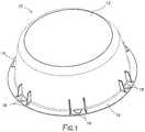
- FIG. 1is a top axonometric view a stackable antenna enclosure 10 .
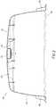
- FIG. 2is side cross-sectional view of the stackable antenna enclosure 10 corresponding to FIG. 1 .
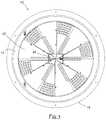
- FIG. 3is a bottom view of the stackable antenna enclosure 10 corresponding to FIGS. 1 and 2 .
- FIG. 4is a top axonometric view of two antenna enclosures 10 a and 10 b stacked together.
- FIG. 5is a side cross-sectional view of two antenna enclosures 10 a, 10 b corresponding to FIG. 4
- FIG. 6is a bottom axonometric view of an alternative embodiment of an antenna enclosure 10 with slots 15 , 17 on its interior side wall 14 for mounting a second antenna 25 .
- FIG. 7is a bottom axonometric view corresponding to FIG. 6 after the second antenna 25 has been mounted in the slots 15 , 17 .
- FIGS. 1-3illustrate an embodiment of a stackable antenna enclosure 10 in accordance with the present invention.
- the enclosure 10is generally dome-shape with a top 12 and a side wall 14 tapering inward from the base 16 to define a cavity within the enclosure 10 .
- the overall shape of the enclosure 10can be generally hemispherical or it can have a truncated conical shape.
- the enclosures 10 a, 10 bshould capable of being stacked or nested together, as shown in FIGS. 4 and 5 , so that the top 12 and upper portion of the side wall 14 of an enclosure 10 b can be inserted into the cavity of an adjacent enclosure 10 a above.
- An antenna 20 and its associated electronic components 22are mounted to the interior surface of the top 12 of the enclosure 10 , as shown in the bottom view provided in FIG. 3 .
- the antennahas a relatively flat profile, but does extend downward by a small distance into the interior cavity of the enclosure 10 as shown in FIG. 2 .
- the enclosure 10protects the antenna 20 and associated electronic components 22 from the elements and also provides a cover for any roof penetrations of the vehicle or structure that the enclosure 10 is mounted to.
- the enclosure 10provides additional height above the mounting surface (i.e., a stand-off distance) to separate the antenna 20 from the vehicle or structure, and thereby enhances the performance of the antenna 20 .
- the enclosure 10is equipped with a number of stops 18 that extend from side wall 14 as illustrated in FIGS. 1 and 2 .
- these stops 18extend outward from the exterior of the side wall 14 at intervals around its periphery at a predetermined elevation above the base 16 .
- these stops 18limit how far the enclosure 10 b can be inserted into the interior cavity of an adjacent enclosure 10 a when these enclosures 10 a, 10 b are nested together. This protects the antenna 20 and related electronic components 22 by preventing them from coming into contact with the top 12 of the adjacent enclosure 10 b.
- the stops 18are a set of at least three vertical ribs or protrusions on the outside of the sidewall 14 of the enclosure 10 adjacent to its base 16 .
- each stop 18has a substantially horizontal upper edge.
- the vertical height of the ribs 18defines a maximum depth of insertion for nesting the enclosures 10 a, 10 b and thereby maintains a minimum vertical separation between the antenna 20 (and its related components 22 ) and the top of an adjacent enclosure 10 b below, as shown in FIG. 5 .
- the antenna 20 and related components 22are protected within the upper part of the cavity remaining between the stacked enclosures 10 a and 10 b.
- the sloping sidewall 14 of the enclosure 10 aalso prevents contact with the outer parts of the enclosure 10 b nested within.
- stops 18include a series of ribs or protrusions on the inside of sidewall 14 to contact the top or upper sidewall of an adjacent enclosure.
- a circumferential lipcould extend outward or inward from the sidewall 14 of the enclosure 10 . If the lip extends outward, this lip would contact the base of an adjacent enclosure above. If the lip extends inward, the lip would contact the top or upper sidewall of the adjacent enclosure below.
- a circumferential lipcould also extend inward from the base 16 of the enclosure 10 to contact the sidewall of an adjacent enclosure.
- FIGS. 6-7show an embodiment of the present invention that includes slots 15 , 17 for mounting electronic devices on the interior side wall 14 of the enclosure.
- a second antenna 25can be equipped with opposing ears or projections that slide into these slots 15 , 17 to mount the antenna 25 (e.g., an AM loop antenna) within the interior cavity of the enclosure, as shown in FIG. 7 .
- the slots 15 , 17could also be employed for mounting other types of electronics modules (e.g., a 4G or wi-fi module) within the enclosure. Multiple sets of such slots could be used to mount multiple antennas or other electronics devices within the enclosure.
Landscapes
- Details Of Aerials (AREA)
Abstract
Description
Claims (17)
Priority Applications (1)
| Application Number | Priority Date | Filing Date | Title |
|---|---|---|---|
| US16/277,079US10770779B2 (en) | 2018-03-01 | 2019-02-15 | Stackable antenna enclosure |
Applications Claiming Priority (2)
| Application Number | Priority Date | Filing Date | Title |
|---|---|---|---|
| US201862637086P | 2018-03-01 | 2018-03-01 | |
| US16/277,079US10770779B2 (en) | 2018-03-01 | 2019-02-15 | Stackable antenna enclosure |
Publications (2)
| Publication Number | Publication Date |
|---|---|
| US20190273301A1 US20190273301A1 (en) | 2019-09-05 |
| US10770779B2true US10770779B2 (en) | 2020-09-08 |
Family
ID=67768180
Family Applications (1)
| Application Number | Title | Priority Date | Filing Date |
|---|---|---|---|
| US16/277,079Expired - Fee RelatedUS10770779B2 (en) | 2018-03-01 | 2019-02-15 | Stackable antenna enclosure |
Country Status (1)
| Country | Link |
|---|---|
| US (1) | US10770779B2 (en) |
Families Citing this family (1)
| Publication number | Priority date | Publication date | Assignee | Title |
|---|---|---|---|---|
| US12407109B2 (en)* | 2021-07-20 | 2025-09-02 | Nicor, Inc. | Underground monopole antenna shell |
Citations (25)
| Publication number | Priority date | Publication date | Assignee | Title |
|---|---|---|---|---|
| US3346865A (en) | 1964-12-10 | 1967-10-10 | Jr Howard S Jones | Slot antenna built into a dielectric radome |
| US3480178A (en) | 1968-09-16 | 1969-11-25 | Henry Z Morgan | Containers that are compactly nestable when empty and stackable in spaced relation when full |
| US3485412A (en) | 1968-08-27 | 1969-12-23 | American Can Co | Stackable plastic container |
| US4101895A (en) | 1977-02-14 | 1978-07-18 | The United States Of America As Represented By The Secretary Of The Army | Multifrequency antenna system integrated into a radome |
| US4460901A (en) | 1981-11-27 | 1984-07-17 | General Dynamics Corporation, Electronics Division | Integrated antenna-radome structure that functions as a self-referencing interferometer |
| US4875132A (en) | 1988-11-03 | 1989-10-17 | Tideland Signal Corporation | Antenna grounding system |
| US5534880A (en) | 1993-03-18 | 1996-07-09 | Gabriel Electronics Incorporated | Stacked biconical omnidirectional antenna |
| US5880701A (en) | 1996-06-25 | 1999-03-09 | Pcs Solutions, Llc | Enclosed wireless telecommunications antenna |
| US6241222B1 (en) | 1998-07-14 | 2001-06-05 | Lantec Products, Inc. | Stacked packing with spacing features |
| US7006054B2 (en)* | 2001-11-02 | 2006-02-28 | Radio Frequency System, Inc. | Antenna and radio interface |
| US7014043B2 (en) | 2001-01-15 | 2006-03-21 | Norseman Plastics, Limited | Multi-level stacking container |
| US7245267B2 (en) | 2005-02-08 | 2007-07-17 | Kathrein-Werke Kg | Mobile radio antenna radome with integral reflector |
| US20080062067A1 (en)* | 2006-09-13 | 2008-03-13 | Antenex, Inc. | Antenna cover |
| JP2008277885A (en) | 2007-04-25 | 2008-11-13 | Mitsubishi Electric Corp | Laminated radome |
| US20090066593A1 (en) | 2007-09-12 | 2009-03-12 | Laird Technologies, Inc. | Vehicle-mount stacked patch antenna assemblies with resiliently compressible bumpers for mechanical compression to aid in electrical grounding of shield and chassis |
| US20090262033A1 (en)* | 2007-02-07 | 2009-10-22 | Lael King | Releasably mountable mobile/transportable motorized antenna system |
| US20110006965A1 (en) | 2009-07-10 | 2011-01-13 | Kits Van Heyningen Martin A | Multi-Antenna Enclosure |
| US20110030015A1 (en)* | 2009-08-01 | 2011-02-03 | Lael King | Enclosed antenna system for receiving broadcasts from multiple sources |
| US20130002515A1 (en)* | 2009-12-11 | 2013-01-03 | Andrew Llc | Radome Attachment Band Clamp |
| US20130207868A1 (en)* | 2012-02-09 | 2013-08-15 | Winegard Company | Enclosure system for an antenna |
| US20130257468A1 (en) | 2012-04-03 | 2013-10-03 | Octoscope Inc. | Stackable Electromagnetically Isolated Test Enclosures |
| US8604987B1 (en) | 2010-06-17 | 2013-12-10 | Rockwell Collins, Inc | Stackable antenna concept for multiband operation |
| US20140057576A1 (en) | 2012-08-27 | 2014-02-27 | Kvh Industries, Inc. | Agile Diverse Polarization Multi-Frequency Band Antenna Feed With Rotatable Integrated Distributed Transceivers |
| CN105281049A (en) | 2015-10-21 | 2016-01-27 | 深圳市安拓浦科技有限公司 | Small-sized integrated antenna base station |
| WO2017082977A1 (en) | 2015-11-11 | 2017-05-18 | Voxx International Corporation | Omni-directional television antenna with wifi reception capability |
- 2019
- 2019-02-15USUS16/277,079patent/US10770779B2/ennot_activeExpired - Fee Related
Patent Citations (26)
| Publication number | Priority date | Publication date | Assignee | Title |
|---|---|---|---|---|
| US3346865A (en) | 1964-12-10 | 1967-10-10 | Jr Howard S Jones | Slot antenna built into a dielectric radome |
| US3485412A (en) | 1968-08-27 | 1969-12-23 | American Can Co | Stackable plastic container |
| US3480178A (en) | 1968-09-16 | 1969-11-25 | Henry Z Morgan | Containers that are compactly nestable when empty and stackable in spaced relation when full |
| US4101895A (en) | 1977-02-14 | 1978-07-18 | The United States Of America As Represented By The Secretary Of The Army | Multifrequency antenna system integrated into a radome |
| US4460901A (en) | 1981-11-27 | 1984-07-17 | General Dynamics Corporation, Electronics Division | Integrated antenna-radome structure that functions as a self-referencing interferometer |
| US4875132A (en) | 1988-11-03 | 1989-10-17 | Tideland Signal Corporation | Antenna grounding system |
| US5534880A (en) | 1993-03-18 | 1996-07-09 | Gabriel Electronics Incorporated | Stacked biconical omnidirectional antenna |
| US5880701A (en) | 1996-06-25 | 1999-03-09 | Pcs Solutions, Llc | Enclosed wireless telecommunications antenna |
| US6241222B1 (en) | 1998-07-14 | 2001-06-05 | Lantec Products, Inc. | Stacked packing with spacing features |
| US7014043B2 (en) | 2001-01-15 | 2006-03-21 | Norseman Plastics, Limited | Multi-level stacking container |
| US7006054B2 (en)* | 2001-11-02 | 2006-02-28 | Radio Frequency System, Inc. | Antenna and radio interface |
| US7245267B2 (en) | 2005-02-08 | 2007-07-17 | Kathrein-Werke Kg | Mobile radio antenna radome with integral reflector |
| US20080062067A1 (en)* | 2006-09-13 | 2008-03-13 | Antenex, Inc. | Antenna cover |
| US20090262033A1 (en)* | 2007-02-07 | 2009-10-22 | Lael King | Releasably mountable mobile/transportable motorized antenna system |
| JP2008277885A (en) | 2007-04-25 | 2008-11-13 | Mitsubishi Electric Corp | Laminated radome |
| US20090066593A1 (en) | 2007-09-12 | 2009-03-12 | Laird Technologies, Inc. | Vehicle-mount stacked patch antenna assemblies with resiliently compressible bumpers for mechanical compression to aid in electrical grounding of shield and chassis |
| US20110006965A1 (en) | 2009-07-10 | 2011-01-13 | Kits Van Heyningen Martin A | Multi-Antenna Enclosure |
| US8368611B2 (en) | 2009-08-01 | 2013-02-05 | Electronic Controlled Systems, Inc. | Enclosed antenna system for receiving broadcasts from multiple sources |
| US20110030015A1 (en)* | 2009-08-01 | 2011-02-03 | Lael King | Enclosed antenna system for receiving broadcasts from multiple sources |
| US20130002515A1 (en)* | 2009-12-11 | 2013-01-03 | Andrew Llc | Radome Attachment Band Clamp |
| US8604987B1 (en) | 2010-06-17 | 2013-12-10 | Rockwell Collins, Inc | Stackable antenna concept for multiband operation |
| US20130207868A1 (en)* | 2012-02-09 | 2013-08-15 | Winegard Company | Enclosure system for an antenna |
| US20130257468A1 (en) | 2012-04-03 | 2013-10-03 | Octoscope Inc. | Stackable Electromagnetically Isolated Test Enclosures |
| US20140057576A1 (en) | 2012-08-27 | 2014-02-27 | Kvh Industries, Inc. | Agile Diverse Polarization Multi-Frequency Band Antenna Feed With Rotatable Integrated Distributed Transceivers |
| CN105281049A (en) | 2015-10-21 | 2016-01-27 | 深圳市安拓浦科技有限公司 | Small-sized integrated antenna base station |
| WO2017082977A1 (en) | 2015-11-11 | 2017-05-18 | Voxx International Corporation | Omni-directional television antenna with wifi reception capability |
Also Published As
| Publication number | Publication date |
|---|---|
| US20190273301A1 (en) | 2019-09-05 |
Similar Documents
| Publication | Publication Date | Title |
|---|---|---|
| US5481438A (en) | Tray for semiconductor devices | |
| RU2004137661A (en) | RF PROTECTIVE SCREEN FOR ELECTRONIC EQUIPMENT | |
| JP4975102B2 (en) | Terminal box | |
| EP3793025B1 (en) | Base station antenna | |
| US7131248B2 (en) | Wafer shipper with orientation control | |
| US10770779B2 (en) | Stackable antenna enclosure | |
| US9673577B2 (en) | Power plug device and the manufacturing method thereof | |
| US11488786B2 (en) | Winding-type capacitor package structure and method of manufacturing the same | |
| US20190386473A1 (en) | Housing, electric connection box and wire harness | |
| CN104883838A (en) | Electronic unit | |
| US20160308286A1 (en) | Din connector end cap | |
| US20070187286A1 (en) | Wafer storage container and apparatus | |
| CN110663111B (en) | Semiconductor device assembly having cover including circuit element | |
| CN104648842B (en) | Bearing device and combination of bearing device and carried object | |
| KR102136994B1 (en) | Camera module | |
| JP7535871B2 (en) | Battery case | |
| CN111532588A (en) | Packing case (food) | |
| US20110253588A1 (en) | Tray assembly | |
| US8567881B2 (en) | Container data center | |
| US20220248576A1 (en) | Electronic component with internal shielding | |
| US20050030723A1 (en) | Fully-molded or lidded circuit module assembly having edge-stiffening interlock features | |
| US9312675B2 (en) | Junction box auxiliary securing structure | |
| US20170055352A1 (en) | Device having circuit board | |
| CN219215893U (en) | Packaging box for photoelectric product | |
| JP3589104B2 (en) | Planar antenna device and antenna cover used therefor |
Legal Events
| Date | Code | Title | Description |
|---|---|---|---|
| AS | Assignment | Owner name:WINEGARD COMPANY, IOWA Free format text:ASSIGNMENT OF ASSIGNORS INTEREST;ASSIGNOR:MINEART, KEVIN JOHN;REEL/FRAME:048345/0053 Effective date:20190213 | |
| FEPP | Fee payment procedure | Free format text:ENTITY STATUS SET TO UNDISCOUNTED (ORIGINAL EVENT CODE: BIG.); ENTITY STATUS OF PATENT OWNER: LARGE ENTITY | |
| STPP | Information on status: patent application and granting procedure in general | Free format text:DOCKETED NEW CASE - READY FOR EXAMINATION | |
| STPP | Information on status: patent application and granting procedure in general | Free format text:NOTICE OF ALLOWANCE MAILED -- APPLICATION RECEIVED IN OFFICE OF PUBLICATIONS | |
| ZAAA | Notice of allowance and fees due | Free format text:ORIGINAL CODE: NOA | |
| ZAAB | Notice of allowance mailed | Free format text:ORIGINAL CODE: MN/=. | |
| STCF | Information on status: patent grant | Free format text:PATENTED CASE | |
| FEPP | Fee payment procedure | Free format text:MAINTENANCE FEE REMINDER MAILED (ORIGINAL EVENT CODE: REM.); ENTITY STATUS OF PATENT OWNER: LARGE ENTITY | |
| LAPS | Lapse for failure to pay maintenance fees | Free format text:PATENT EXPIRED FOR FAILURE TO PAY MAINTENANCE FEES (ORIGINAL EVENT CODE: EXP.); ENTITY STATUS OF PATENT OWNER: LARGE ENTITY | |
| STCH | Information on status: patent discontinuation | Free format text:PATENT EXPIRED DUE TO NONPAYMENT OF MAINTENANCE FEES UNDER 37 CFR 1.362 | |
| FP | Lapsed due to failure to pay maintenance fee | Effective date:20240908 |