US10769913B2 - Cloud-based video surveillance management system - Google Patents
Cloud-based video surveillance management systemDownload PDFInfo
- Publication number
- US10769913B2 US10769913B2US13/335,591US201113335591AUS10769913B2US 10769913 B2US10769913 B2US 10769913B2US 201113335591 AUS201113335591 AUS 201113335591AUS 10769913 B2US10769913 B2US 10769913B2
- Authority
- US
- United States
- Prior art keywords
- metadata
- video
- noise
- video content
- filtered set
- Prior art date
- Legal status (The legal status is an assumption and is not a legal conclusion. Google has not performed a legal analysis and makes no representation as to the accuracy of the status listed.)
- Active, expires
Links
- 238000000034methodMethods0.000claimsabstractdescription73
- 238000012545processingMethods0.000claimsabstractdescription47
- 230000008569processEffects0.000claimsdescription35
- 238000001914filtrationMethods0.000claimsdescription10
- 230000002123temporal effectEffects0.000claimsdescription10
- 238000004590computer programMethods0.000claimsdescription7
- 230000004044responseEffects0.000claimsdescription4
- 238000004891communicationMethods0.000description11
- 238000010586diagramMethods0.000description11
- 230000003936working memoryEffects0.000description8
- 238000012544monitoring processMethods0.000description7
- 230000006870functionEffects0.000description6
- 230000008859changeEffects0.000description5
- 230000033001locomotionEffects0.000description5
- 230000003287optical effectEffects0.000description5
- 230000005540biological transmissionEffects0.000description4
- 230000006835compressionEffects0.000description4
- 238000007906compressionMethods0.000description4
- 238000001514detection methodMethods0.000description4
- 238000011897real-time detectionMethods0.000description4
- 238000012546transferMethods0.000description4
- 238000009434installationMethods0.000description3
- 230000015654memoryEffects0.000description3
- 230000003068static effectEffects0.000description3
- 230000004075alterationEffects0.000description2
- 238000004458analytical methodMethods0.000description2
- 230000000694effectsEffects0.000description2
- 230000000007visual effectEffects0.000description2
- RYGMFSIKBFXOCR-UHFFFAOYSA-NCopperChemical compound[Cu]RYGMFSIKBFXOCR-UHFFFAOYSA-N0.000description1
- 241000274965Cyrestis thyodamasSpecies0.000description1
- 206010052128GlareDiseases0.000description1
- 241001465754MetazoaSpecies0.000description1
- 230000001133accelerationEffects0.000description1
- 230000009471actionEffects0.000description1
- 238000013459approachMethods0.000description1
- 239000010426asphaltSubstances0.000description1
- 230000006399behaviorEffects0.000description1
- 230000010267cellular communicationEffects0.000description1
- 230000000295complement effectEffects0.000description1
- 238000010276constructionMethods0.000description1
- 230000006837decompressionEffects0.000description1
- 238000005516engineering processMethods0.000description1
- 239000000835fiberSubstances0.000description1
- 230000004313glareEffects0.000description1
- 238000003384imaging methodMethods0.000description1
- 230000010354integrationEffects0.000description1
- 238000013178mathematical modelMethods0.000description1
- 230000007246mechanismEffects0.000description1
- 239000000203mixtureSubstances0.000description1
- 238000012986modificationMethods0.000description1
- 230000004048modificationEffects0.000description1
- 238000012805post-processingMethods0.000description1
- 230000009467reductionEffects0.000description1
- 239000004065semiconductorSubstances0.000description1
- 230000009466transformationEffects0.000description1
Images


Classifications
- G—PHYSICS
- G08—SIGNALLING
- G08B—SIGNALLING OR CALLING SYSTEMS; ORDER TELEGRAPHS; ALARM SYSTEMS
- G08B13/00—Burglar, theft or intruder alarms
- G08B13/18—Actuation by interference with heat, light, or radiation of shorter wavelength; Actuation by intruding sources of heat, light, or radiation of shorter wavelength
- G08B13/189—Actuation by interference with heat, light, or radiation of shorter wavelength; Actuation by intruding sources of heat, light, or radiation of shorter wavelength using passive radiation detection systems
- G08B13/194—Actuation by interference with heat, light, or radiation of shorter wavelength; Actuation by intruding sources of heat, light, or radiation of shorter wavelength using passive radiation detection systems using image scanning and comparing systems
- G08B13/196—Actuation by interference with heat, light, or radiation of shorter wavelength; Actuation by intruding sources of heat, light, or radiation of shorter wavelength using passive radiation detection systems using image scanning and comparing systems using television cameras
- G08B13/19665—Details related to the storage of video surveillance data
- G08B13/19671—Addition of non-video data, i.e. metadata, to video stream
- G—PHYSICS
- G08—SIGNALLING
- G08B—SIGNALLING OR CALLING SYSTEMS; ORDER TELEGRAPHS; ALARM SYSTEMS
- G08B13/00—Burglar, theft or intruder alarms
- G08B13/18—Actuation by interference with heat, light, or radiation of shorter wavelength; Actuation by intruding sources of heat, light, or radiation of shorter wavelength
- G08B13/189—Actuation by interference with heat, light, or radiation of shorter wavelength; Actuation by intruding sources of heat, light, or radiation of shorter wavelength using passive radiation detection systems
- G08B13/194—Actuation by interference with heat, light, or radiation of shorter wavelength; Actuation by intruding sources of heat, light, or radiation of shorter wavelength using passive radiation detection systems using image scanning and comparing systems
- G08B13/196—Actuation by interference with heat, light, or radiation of shorter wavelength; Actuation by intruding sources of heat, light, or radiation of shorter wavelength using passive radiation detection systems using image scanning and comparing systems using television cameras
- G08B13/19639—Details of the system layout
- G08B13/19641—Multiple cameras having overlapping views on a single scene
- G08B13/19643—Multiple cameras having overlapping views on a single scene wherein the cameras play different roles, e.g. different resolution, different camera type, master-slave camera
- G—PHYSICS
- G08—SIGNALLING
- G08B—SIGNALLING OR CALLING SYSTEMS; ORDER TELEGRAPHS; ALARM SYSTEMS
- G08B13/00—Burglar, theft or intruder alarms
- G08B13/18—Actuation by interference with heat, light, or radiation of shorter wavelength; Actuation by intruding sources of heat, light, or radiation of shorter wavelength
- G08B13/189—Actuation by interference with heat, light, or radiation of shorter wavelength; Actuation by intruding sources of heat, light, or radiation of shorter wavelength using passive radiation detection systems
- G08B13/194—Actuation by interference with heat, light, or radiation of shorter wavelength; Actuation by intruding sources of heat, light, or radiation of shorter wavelength using passive radiation detection systems using image scanning and comparing systems
- G08B13/196—Actuation by interference with heat, light, or radiation of shorter wavelength; Actuation by intruding sources of heat, light, or radiation of shorter wavelength using passive radiation detection systems using image scanning and comparing systems using television cameras
- G08B13/19639—Details of the system layout
- G08B13/19645—Multiple cameras, each having view on one of a plurality of scenes, e.g. multiple cameras for multi-room surveillance or for tracking an object by view hand-over
- G—PHYSICS
- G08—SIGNALLING
- G08B—SIGNALLING OR CALLING SYSTEMS; ORDER TELEGRAPHS; ALARM SYSTEMS
- G08B13/00—Burglar, theft or intruder alarms
- G08B13/18—Actuation by interference with heat, light, or radiation of shorter wavelength; Actuation by intruding sources of heat, light, or radiation of shorter wavelength
- G08B13/189—Actuation by interference with heat, light, or radiation of shorter wavelength; Actuation by intruding sources of heat, light, or radiation of shorter wavelength using passive radiation detection systems
- G08B13/194—Actuation by interference with heat, light, or radiation of shorter wavelength; Actuation by intruding sources of heat, light, or radiation of shorter wavelength using passive radiation detection systems using image scanning and comparing systems
- G08B13/196—Actuation by interference with heat, light, or radiation of shorter wavelength; Actuation by intruding sources of heat, light, or radiation of shorter wavelength using passive radiation detection systems using image scanning and comparing systems using television cameras
- G08B13/19654—Details concerning communication with a camera
- G08B13/19656—Network used to communicate with a camera, e.g. WAN, LAN, Internet
- H—ELECTRICITY
- H04—ELECTRIC COMMUNICATION TECHNIQUE
- H04N—PICTORIAL COMMUNICATION, e.g. TELEVISION
- H04N21/00—Selective content distribution, e.g. interactive television or video on demand [VOD]
- H04N21/40—Client devices specifically adapted for the reception of or interaction with content, e.g. set-top-box [STB]; Operations thereof
- H04N21/43—Processing of content or additional data, e.g. demultiplexing additional data from a digital video stream; Elementary client operations, e.g. monitoring of home network or synchronising decoder's clock; Client middleware
- H04N21/44—Processing of video elementary streams, e.g. splicing a video clip retrieved from local storage with an incoming video stream or rendering scenes according to encoded video stream scene graphs
- H04N21/44008—Processing of video elementary streams, e.g. splicing a video clip retrieved from local storage with an incoming video stream or rendering scenes according to encoded video stream scene graphs involving operations for analysing video streams, e.g. detecting features or characteristics in the video stream
- H—ELECTRICITY
- H04—ELECTRIC COMMUNICATION TECHNIQUE
- H04N—PICTORIAL COMMUNICATION, e.g. TELEVISION
- H04N21/00—Selective content distribution, e.g. interactive television or video on demand [VOD]
- H04N21/40—Client devices specifically adapted for the reception of or interaction with content, e.g. set-top-box [STB]; Operations thereof
- H04N21/47—End-user applications
- H04N21/482—End-user interface for program selection
- H04N21/4828—End-user interface for program selection for searching program descriptors
- H—ELECTRICITY
- H04—ELECTRIC COMMUNICATION TECHNIQUE
- H04N—PICTORIAL COMMUNICATION, e.g. TELEVISION
- H04N21/00—Selective content distribution, e.g. interactive television or video on demand [VOD]
- H04N21/80—Generation or processing of content or additional data by content creator independently of the distribution process; Content per se
- H04N21/81—Monomedia components thereof
- H04N21/8126—Monomedia components thereof involving additional data, e.g. news, sports, stocks, weather forecasts
- H04N21/8133—Monomedia components thereof involving additional data, e.g. news, sports, stocks, weather forecasts specifically related to the content, e.g. biography of the actors in a movie, detailed information about an article seen in a video program
- H—ELECTRICITY
- H04—ELECTRIC COMMUNICATION TECHNIQUE
- H04N—PICTORIAL COMMUNICATION, e.g. TELEVISION
- H04N7/00—Television systems
- H04N7/18—Closed-circuit television [CCTV] systems, i.e. systems in which the video signal is not broadcast
- H04N7/181—Closed-circuit television [CCTV] systems, i.e. systems in which the video signal is not broadcast for receiving images from a plurality of remote sources
Definitions
- Security camerasare commonly used to monitor indoor and outdoor locations. Networks of security cameras may be used to monitor a given area. For example, hundreds of cameras may be used to provide video feeds of sections of a college campus. Cameras within a security camera network are typically not aware of their location within the system or the existence and locations of other cameras in the system. Thus, a user monitoring video feeds produced by the security cameras manually analyzes and processes the video feeds to track and locate objects within the monitored area. Additionally, conventional security camera networks operate as a closed system, in which networked security cameras provide video feeds for a single geographic area and a user observes the video feeds and operates the network from a fixed-location user terminal located at the same geographic area.
- An example of a method of managing a video surveillance systemincludes obtaining video content and metadata relating to the video content from multiple network devices; filtering the metadata according to one or more criteria to obtain a filtered set of metadata; isolating video portions, of the video content, associated with respective first portions of the filtered set of metadata; and providing at least some of the filtered set of metadata or the isolated video portions to a cloud computing service.
- Implementations of the methodcan include one or more of the following features.
- the network devicescomprise at least one of cameras or video encoders. Respective ones of the network devices are associated with respective local networks, and each of the local networks is associated with distinct geographic locations. Evaluating quality of the metadata according to the one or more criteria, classifying second portions of the metadata having a quality below a threshold as noise metadata, and excluding the noise metadata from the filtered set of metadata. Obtaining the metadata from at least a first network device and a second network device, where the first network device and the second network device maintain metadata for overlapping geographic areas.
- the metadatacorrespond to at least one of objects tracked within the video surveillance system or events within the video surveillance system. Processing the video content to generate one or more supplementary metadata elements. Receiving a query of at least one of the metadata or the video content and processing the query according to one or more predefined rules.
- An example of a video surveillance management systemincludes a gateway configured to obtain video content and metadata relating to the video content from multiple network devices; a metadata processing module communicatively coupled to the gateway and configured to filter the metadata according to one or more criteria to obtain a filtered set of metadata; a video processing module communicatively coupled to the gateway and the metadata processing module and configured to isolate video portions, of video the content, associated with respective first portions of the filtered set of metadata; and a cloud services interface communicatively coupled to the gateway, the metadata processing module and the video processing module and configured to provide at least some of the filtered set of metadata or the isolated video portions to a cloud computing service.
- Implementations of the systemcan include one or more of the following features.
- the network devicescomprise at least one of cameras or video encoders.
- the metadata processing moduleis further configured to evaluate quality of the metadata according to the one or more criteria, to classify respective second portions of the metadata having a quality below a threshold as noise metadata, and to exclude the noise metadata from the filtered set of metadata.
- the gatewayis further configured to obtain the metadata from at least a first network device and a second network device, wherein the first network device and the second network device maintain metadata for overlapping geographic areas, and the metadata processing module is further configured to identify a metadata element obtained from the first network device that corresponds to an area for which the first network device and the second network device maintain metadata, to determine whether a corresponding metadata element has been obtained from the second network device, and to classify the metadata element as noise if the corresponding metadata element has not been obtained from the second network device.
- the metadata processing moduleis further configured to evaluate the quality of the metadata based on at least one of spatial relationships within video content corresponding to the metadata or temporal relationships within the video content corresponding to the metadata.
- the metadata processing moduleis further configured to identify a metadata element associated with an object detected by a network device and to classify the metadata element as noise if the object disappears within a threshold amount of time from its appearance or if the object exhibits at least a threshold degree of change with respect to moving direction, size or moving speed.
- the metadatacorrespond to at least one of objects tracked within the video surveillance system or events within the video surveillance system.
- the video processing moduleis further configured to generate one or more supplementary metadata elements based on the video content.
- a rule enginecommunicatively coupled to the gateway, the metadata processing module and the video processing module and configured to receive a query of at least one of the metadata or the video content and to process the query according to one or more predefined rules.
- Another example of a video surveillance management systemincludes network interface means for obtaining video content and metadata relating to the video content from multiple network devices; metadata processing means, communicatively coupled to the network interface means, for filtering the metadata according to one or more criteria to obtain a filtered set of metadata; and video processing means, communicatively coupled to the network interface means and the metadata processing means, for isolating video portions, of the video content, associated with respective first portions of the filtered set of metadata; where the network interface means comprises means for providing at least some of the filtered set of metadata or the isolated video portions to a cloud computing service.
- Implementations of the systemcan include one or more of the following features.
- the network devicescomprise at least one of cameras or video encoders.
- the metadatacorrespond to at least one of objects tracked within the video surveillance system or events within the video surveillance system.
- Query processing meanscommunicatively coupled to the network interface means, the metadata processing means and the video processing means, for receiving a query of at least one of the metadata or the video content and processing the query according to one or more predefined rules.
- An example of a computer program productresides on a processor-executable computer storage medium and includes processor-executable instructions configured to cause a processor to obtain video content and metadata relating to the video content from multiple network devices; filter the metadata according to one or more criteria to obtain a filtered set of metadata; isolate video portions, of the video content, associated with respective first portions of the filtered set of metadata; and provide at least some of the filtered set of metadata or the isolated video portions to a cloud computing service.
- Implementations of the computer program productmay include one or more of the following features.
- the network devicescomprise at least one of cameras or video encoders.
- the instructions configured to cause the processor to filterare further configured to cause the processor to evaluate quality of the metadata according to the one or more criteria, classify second portions of the metadata having a quality below a threshold as noise metadata, and exclude the noise metadata from the filtered set of metadata.
- the metadatacorrespond to at least one of objects tracked within the video surveillance system or events within the video surveillance system.
- Processor-executable instructionsconfigured to cause the processor to receive a query of at least one of the metadata or the video content and process the query according to one or more predefined rules.
- Video content and metadataare provided to and processed by a cloud-based service, enabling oversight and operation of a security camera network from any location, including locations remote to the security camera network.
- Cloud-based security camera network management servicescan be utilized to enable a single consolidated interface for oversight and operation of multiple security camera networks in different geographic areas.
- Video content and metadata provided to the cloud storage facilityare intelligently selected, significantly reducing the costs associated with data transfer.
- Network video and metadata processing algorithmscan be utilized to provide enhanced video analytics by leveraging relationships between cameras in a system of managed security camera networks.
- a rule enginecan be implemented to provide enhanced querying and retrieval of data provided to a cloud-based service.
- Other capabilitiesmay be provided and not every implementation according to the disclosure must provide any, let alone all, of the capabilities discussed. Further, it may be possible for an effect noted above to be achieved by means other than that noted, and a noted item/technique may not necessarily yield the noted effect.
- FIG. 1is a block diagram of a security camera network.
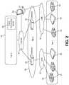
- FIG. 2is a diagram of a three-tier cloud-based video surveillance management system.
- FIG. 3is a diagram illustrating enhanced functionality provided by the video surveillance management system of FIG. 2 .
- FIG. 4is a block diagram of a system for managing a set of video surveillance networks.
- FIG. 5is a diagram illustrating cloud computing services provided by a cloud-based video surveillance management system.
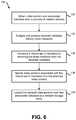
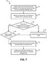
- FIGS. 6-7are block flow diagrams of processes for managing transfer of information associated with a video surveillance system to a network management service.
- FIG. 8illustrates a block diagram of an embodiment of a computer system.
- the video surveillance management systemapplies video analytics to extract metadata for video content provided to the system from various cameras and other associated devices.
- the video content and metadataare, in turn, used to assist video management operations such as event and alarm management and decision assistance.
- Each camera in a camera networkhas an associated point of view and field of view.
- a point of viewrefers to the position and perspective from which a physical region is being viewed by a camera.
- a field of viewrefers to the physical region imaged in frames by the camera.
- Each camerais equipped with an imaging module, implemented as a complementary metal-oxide-semiconductor (CMOS) device and/or by other means, that generates images from received light, as well as a computational engine that takes images of a given resolution at a predefined rate (e.g., 30 images/second, etc.), compresses the image data using a visual compression algorithm and sends the compressed data over a local connection.
- CMOScomplementary metal-oxide-semiconductor
- a camerafurther includes, or is associated with, a digital signal processor (DSP) and associated software that manages operation of the camera.
- DSPdigital signal processor
- the DSPbegins to capture images using the functional modules described above.
- the DSPmaintains a mathematical model that describes an expected behavior of the particular pixel. For instance, for a camera mounted such that it captures images of a parking lot, one pixel position within the images captured by the camera may correspond to asphalt on the surface of the parking lot.
- the pixelhas a static digital value that changes over time due to noise, lighting changes, and the like.
- the DSPmodels these variations over time as, e.g., a Gaussian distribution of a given mean and standard deviation.
- the DSPcan generate similar models for pixels that change in a more complex manner, such as a pixel corresponding to a location on the side of a building that is at times obscured by a tree branch moving in the wind.
- the DSPcan process frames to determine whether a moving object is present within its field of view.
- the cameraassociates metadata with images of the moving object (referred to as an “object” for short).
- These metadatadefine various characteristics of the object.
- the metadatacan define the location of the object within the camera's field of view, the width or height of the image of the object (e.g., measured in pixels), the direction the image of the object is moving, the speed of the image of the object, the color of the object, and/or a category of object.
- the category of objectrefers to a category, based on other characteristics of the object, that the object is determined to be within.
- categoriescan include: humans, animals, cars, small trucks, large trucks, and/or SUVs.
- Metadata regarding events involving moving objectsis also transmitted by the camera to the host computer system.
- Such event metadataincludes: an object entering the field of view of the camera, an object leaving the field of view of the camera, the camera being sabotaged, the object remaining in the camera's field of view for greater than a threshold period of time (e.g., if a person is loitering in an area for greater than some threshold period of time), multiple moving objects merging (e.g., a running person jumps into a moving vehicle), a moving object splitting into multiple moving objects (e.g., a person gets out of a vehicle), an object entering an area of interest (e.g., a predefined area where the movement of objects is desired to be monitored), an object leaving a predefined zone, an object crossing a tripwire, an object moving in a direction matching a predefined forbidden direction for a zone or tripwire, object counting, object removal (e.g., when an object is still longer than a predefined period of time and its size is larger than a large portion of a predefined zone), object abandonment (e.g., when an object is
- Each cameratransmits metadata associated with images of moving objects to a host computer system.
- Each cameraalso transmits frames of a video feed, possibly compressed, to the host computer system.
- the host computer systemenables a user to view and analyze the video content and metadata. For instance, using the metadata received from multiple cameras, the host computer system can determine whether images of moving objects that appear (either simultaneously or non-simultaneously) in the fields of view of different cameras represent the same object. If a user specifies that this object is to be tracked, the host computer system displays to the user frames of the video feed from a camera determined to have a preferable view of the object. This tracking can also be performed using historical video feeds, referring to stored video feeds that represent movement of the object at some point in the past.
- a usercan specify one or more rules, in response to which the host computer system returns video content and/or metadata that matches the specified rules. For instance, a user can request all video clips captured by the security camera network within a given time range that contain objects of a specified color. Other rules are also possible.
- FIG. 1illustrates a block diagram of a local security camera network 10 .
- the security camera network 10includes video cameras including fixed position cameras 12 , PTZ (Pan-Tilt-Zoom) cameras 14 , slave cameras 16 , etc.
- Security camera networksmay have zero, one, or more than one of each type of camera such that networks may have one or more cameras.
- the security camera network 10includes two fixed position cameras 12 , one PTZ camera 14 and one slave camera 16 .
- Other quantities and/or configurations of camerascould also be used.
- the security camera network 10also includes a router 20 .
- the fixed position cameras 12 , PTZ cameras 14 , and slave cameras 16communicate with the router 20 using a wired connection (e.g., a local area network (LAN) connection) or a wireless connection.
- the router 20communicates with a computing system, such as a host computer system 30 .
- the router 20communicates with the host computer system 30 using either a wired connection, such as a LAN connection, or a wireless connection.
- the host computer system 30may be located at a single computing device and/or multiple computing devices (e.g., as a distributed computer system).
- a fixed position camera 12may be set in a fixed position, such as mounted to the eaves of a building to capture a video feed of the building's emergency exit. The field of view of such a fixed position camera, unless moved or adjusted by some external force, will remain unchanged.
- the fixed position camera 12includes a digital signal processor (DSP) and/or one or more other processing entities to compress, process, and/or analyze images captured by the fixed position camera 12 . For instance, as frames of the field of view of the fixed position camera 12 are captured, these frames are processed by a digital signal processor associated with the fixed position camera 12 to determine if one or more moving objects are present.
- DSPdigital signal processor
- a Gaussian mixture modelmay be used to separate a foreground that contains images of moving objects from a background that contains images of static objects, such as trees, buildings, and roads. The images of these moving objects are then processed to identify various characteristics of the images of the moving objects.
- Metadata associated with, or linked to, an objectcontains information regarding various characteristics of the images of the object.
- the metadataincludes information on characteristics such as: a location of the object, a height of the object, a width of the object, the direction the object is moving in, the speed the object is moving at, a color of the object, and/or a categorical classification of the object.
- Metadatamay also include information regarding events involving moving objects.
- the location of the object in the metadatais expressed as two-dimensional coordinates in a two-dimensional coordinate system associated with fixed position camera 12 .
- These two-dimensional coordinatesare associated with the position of the image of the object in the frames captured by the fixed position camera 12 .
- the two-dimensional coordinates of the objectmay be determined to be a point within the frames captured by the fixed position camera 12 .
- the coordinates of the position of the objectis determined to be the middle of the lowest portion of the object (e.g., if the object is a person standing up, the position would be between the person's feet).
- the two-dimensional coordinateshave an x and y component, but no third component.
- the x and y componentsare measured in numbers of pixels. For example, a location of ⁇ 613, 427 ⁇ would mean that the middle of the lowest portion of the object is 613 pixels along the x-axis and 427 pixels along the y-axis of the field of view of the fixed position camera 12 . As the object moves, the coordinates associated with the location of the object would change. Further, because this coordinate system is associated with the fixed position camera 12 , if the same object is also visible in the fields of views of one or more other cameras, the location coordinates of the object determined by the other cameras would likely be different.
- the height of the objectmay also be contained in the metadata and expressed in terms of numbers of pixels.
- the height of the objectis defined as the number of pixels from the bottom of the image of the object to the top of the image of the object. As such, if the object is close to the fixed position camera 12 , the measured height would be greater than if the object is further from the fixed position camera 12 .
- the width of the objectis expressed in a number of pixels. The width of the objects can be determined based on the average width of the object or the width at the object's widest point that is laterally present in the image of the object. Similarly, the speed and direction of the object can also be measured in pixels.
- the metadata determined by the fixed position camera 12is transmitted to a host computer system 30 via a router 20 .
- the fixed position camera 12transmits a video feed of frames to the host computer system 30 .
- Frames captured by the fixed position camera 12can be compressed or uncompressed. Following compression, the frames are transmitted via the router 20 to the host computer system 30 .
- a security camera network 10may include multiple fixed position cameras 12 , which may function in a substantially similar manner to that described above. Fixed position cameras 12 , assuming they are located in positions different from each other, have different points of view and fields of view. Thus, even if the same object is observed by multiple fixed position cameras 12 at the same instant in time, the perceived location, width and height of the object would vary between the different cameras.
- the security camera network 10also includes a PTZ camera 14 .
- a PTZ camera 14may pan, tilt, and zoom.
- the PTZ camera 14can also include a digital signal processor and/or other processing devices.
- the PTZ camera 14may have predefined points of view at which the PTZ camera 14 has analyzed the background and can distinguish the foreground containing moving objects from the background containing static objects.
- a user using the host computer system 30may be able to control the movement and zoom of the PTZ camera 14 .
- Commands to control the PTZ camera 14may be routed from the host computer system 30 to the PTZ camera 14 via the router 20 .
- the PTZ camera 14follows a set pan, tilt, and zoom pattern unless interrupted by a command from the host computer system 30 .
- the slave camera 16may communicate with the host computer system 30 via the router 20 .
- the slave camera 16can either be a fixed position camera or a PTZ camera.
- the slave camera 16is configured only to capture images and is not capable of identifying objects in the captured images. Instead, the slave camera 16 transmits either raw frames of a video feed or compressed frames of the video feed (e.g., processed via a video compressor) to the host computer system 30 via the router 20 .
- the host computer system 30processes frames received from the slave camera 16 to identify and track moving objects in the frames received from the slave camera 16 .
- the host computer system 30is configured to process information received by the cameras 12 - 16 via the router 20 .
- the host computer system 30can act as a location server which receives and stores locations of respective cameras 12 - 16 and/or other devices within the security camera network 10 .
- the host computer system 30computes locations of devices within the security camera network 10 based on information obtained from a user and/or the devices themselves, or alternatively devices within the security camera network 10 can compute their own locations and submit these locations to the host computer system 30 .
- the host computer system 30also identifies and tracks locations of respective objects monitored by the cameras 12 - 16 .
- the host computer system 30receives and stores compressed and/or uncompressed video from the cameras 12 - 16 .
- the host computer system 30also receives, stores, and analyzes metadata received from the cameras 12 - 16 .
- the host computer system 30can provide a user terminal or other mechanisms that allow a user, such as a security guard, to interact with the frames of the video feeds received from the cameras and any generated metadata associated with the video feeds.
- a user terminal at the host computer system 30can display one or more video feeds to the user at one time. The user can select an object to track using the user terminal.
- the usercan select the image of the object.
- the host computer system 30leverages the positions of the cameras 12 - 16 of the security camera network 10 to track the object as it moves between the fields of view of the cameras 12 - 16 . If the object is visible in the fields of view of multiple cameras, a preferable field of view is selected by the host computer system 30 based on predefined rules. The user can also control the PTZ camera 14 using the host computer system 30 .
- the host computer system 30may be implemented by one computing device or multiple computing devices.
- one computing devicemay process and store device locations, video, and function as a user terminal.
- a first computing devicemay function as a user terminal and interact (e.g., through the router 20 ) with a second computing device that processes location data, video content and/or metadata.
- the local security camera network 10is associated with a number of limitations. For instance, the security camera network 10 does not provide mobility of video; video content and associated data are available only at the host computer system 30 , which is typically physically located in a local control room within the same site at which the cameras 12 - 16 are deployed. Further, the security camera network 10 operates as an insular system and is not configured to receive or utilize video content or other information corresponding to entities outside the local security camera network 10 . Within the security camera network 10 , the host computer system 30 may also not be capable of performing analytics for information associated with multiple cameras 12 - 16 ; instead, the host computer system 30 may provide only a user interface that enables an operator of the security camera network 10 to manually inspect and analyze data associated with multiple cameras 12 - 16 .
- FIG. 2illustrates an example of a three-tier cloud-based system for intelligent video surveillance system management.
- the first tier 40 of the systemincludes edge devices such as routers 20 , intelligent encoders and intelligent cameras 42 with embedded video analytics algorithms.
- the cameras 42 in FIG. 2operate similarly to cameras 12 - 16 in FIG. 1 .
- the first tier 40 of the systemconnects to the second tier 50 of the system through one or more LANs 32 .
- the second tier 50 of the systemis at the gateway of the surveillance system and includes one or more gateway devices 52 that operate as described in further detail below.
- the second tier 50 of the systemconnects via the Internet 34 to the third tier 60 of the system, which includes cloud computing services provided via a cloud computing server 62 and/or other entities.
- a computer system 64can be configured to access information associated with the system via the LAN(s) 32 and/or the Internet 34 .
- the computer system 64includes a user interface (UI) as well as various functional modules to enable an operator to query, process and view data associated with the system in an intelligent manner.
- UIuser interface
- the computer system 64may be located in any suitable location and need not be co-located with any particular edge device(s) or gateway(s) associated with the system.
- a video analytics algorithmis utilized as a scene analyzer to detect and track objects in the scene and generate metadata to describe the objects and their events.
- the scene analyzeroperates as a background subtraction based algorithm.
- the scene analyzercan describe an object with its color, location in the scene, time stamp, velocity, size, moving direction, etc.
- the scene analyzercan also trigger predefined metadata events such as zone or tripwire violation, counting, camera sabotage, object merging, object splitting, still objects, object loitering, etc.
- Object and event metadata, along with any other metadata generated by the edge device(s),are sent to the gateway 52 .
- the gateway 52is a storage and processing device in the local network which stores video and metadata content.
- the gatewaycan be wholly or in part implemented as a network video recorder or an independent server.
- metadata generated from edge devicesare provided to their corresponding gateway 52 .
- the gateway 52uploads video captured from the cameras 42 to the cloud computing server 62 for storage, display, and search. Since the volume of the video captured by the cameras 42 is significantly large, it may be prohibitively expensive in terms of cost and bandwidth to upload all the video content associated with the cameras 42 . Thus, the gateway 52 is utilized as described below to reduce the amount of video sent to the cloud computing server 62 .
- the amount of information sent to the cloud computing server 62 from the gateway 52can be reduced significantly (e.g., to a few percent of the information that would be sent to the cloud computing server 62 if the system sent all information continuously). In addition to cost and bandwidth savings, this reduction improves the scalability of the system, enabling a common platform for monitoring and analyzing surveillance networks across a large number of geographic areas from a single computing system 64 via the cloud computing server 62 .
- the metadata provided by the edge devicesis processed at the gateway 52 to remove noise and reduce duplicated objects.
- Key frames of video content obtained from the edge devicescan also be extracted based on metadata time stamps and/or other information associated with the video and stored as still pictures for post-processing.
- the recorded video and still picturescan be further analyzed to extract information that is not obtained from the edge devices using enhanced video analytics algorithms on the gateway 52 .
- algorithmssuch as face detection/recognition and license plate recognition can be executed at the gateway 52 to extract information based on motion detection results from the associated cameras 42 .
- An enhanced scene analyzercan also be run at the gateway 52 , which can be used to process high definition video content to extract better object features.
- the gateway 52By filtering noisy metadata, the gateway 52 reduces the amount of data uploaded to the cloud computing servers 62 . Conversely, if the scene analyzer at the gateway 52 is not configured correctly, it is possible that a lot of noises will be detected as objects and sent out as metadata. For instance, foliage, flags and some shadows and glares can generate false objects at the edge devices, and it is conventionally difficult for these edge devices to detect and remove such kinds of noise in real time. However, the gateway 52 can leverage temporal and spatial information across all cameras 42 and/or other edge devices in the local surveillance network to filter these noise objects with less difficulty. Noise filtering can be implemented at an object level based on various criteria.
- an objectcan be classified as noise if it disappears soon after it appears, if it changes moving direction, size, and/or moving speed, if it suddenly appears and then stands still, etc. If two cameras have an overlapped area and they are registered to each other (e.g., via a common map), an object identified on one camera can also be identified as noise if it cannot be found at the surrounding area of the location on the other camera. Other criteria may also be used. Detection of noise metadata as performed above can be based on predefined thresholds; for example, an object can be classified as noise if it disappears within a threshold amount of time from its appearance or if it exhibits more than a threshold change to direction, size and/or speed.
- the gateway 52is able to filter out most of the false motion information provided by the edge devices before it is sent to the cloud. For instance, the system can register cameras 42 on a map via a perspective transformation at the gateway 52 , and the feature points of the scene can be registered with the corresponding points on the map. This approach enables the system to function as a cross-camera surveillance monitoring system. Since objects can be detected from multiple cameras 42 in the areas at which the cameras 42 overlap, it is possible to use this information to remove noise from metadata objects.
- the gateway 52can leverage temporal relationships between objects in a scene monitored by edge devices to facilitate consistency in object detection and reduce false positives.
- an edge devicemay generate metadata corresponding to a person walking through the parking lot. If the full body of the person is visible at the camera, the camera generates metadata corresponding to the height of the person. If subsequently, however, the person walks between rows of cars in the parking lot such that his lower body is obscured from the camera, the camera will generate new metadata corresponding to the height of only the visible portion of the person.
- the gateway 52can intelligently analyze the objects observed by the camera, the gateway 52 can leverage temporal relationships between observed objects and pre-established rules for permanence and feature continuity to track an object even if various portions of the object become obscured.
- the remaining metadata objects and associated video contentare uploaded by the gateway 52 to a cloud computing service.
- a cloud computing serviceAs a result of the processing at the gateway 52 , only video clips associated with metadata will be uploaded to the cloud. This can significantly reduce (e.g., by 90% or more) the amount of data to be transmitted.
- the raw video and metadata processed by the gateway 52may also be locally stored at the gateway 52 as backup.
- the gateway 52may also transmit representations of video content and/or metadata to the cloud service in place of, or in addition to, the content or metadata themselves.
- the gateway 52may transmit coordinates or a map representation of the object (e.g., an avatar or other marking corresponding to a map) in place of the actual video content and/or metadata.
- coordinates or a map representation of the objecte.g., an avatar or other marking corresponding to a map
- the video uploaded to the cloud computing server 62can be transcoded with a lower resolution and/or frame rate to reduce video bandwidth on the Internet 34 for a large camera network.
- the gateway 52can convert high-definition video coded in a video compression standard to a low-bandwidth video format in order to reduce the amount of data uploaded to the cloud.
- users associated with the systemcan watch and search video associated with the system anywhere at any time via a user interface provided at any suitable fixed or portable computing device 64 .
- the user interfacecan be web-based (e.g., implemented via HTML 5, Flash, Java, etc.) and implemented via a web browser, or alternatively the user interface can be provided as a dedicated application on one or more computing platforms.
- the computing device 64may be a desktop or laptop computer, tablet computer, smartphone, personal digital assistant (PDA) and/or any other suitable device.
- the systemcan be utilized to integrate a wide network of surveillance systems corresponding to, e.g., different physical branches of a corporate entity.
- the systemenables a user at a single computing device 64 to watch and search video being uploaded to the cloud service from any of the associated locations.
- the cloud servicecan execute the search on a cluster of computers in parallel to speed up the search.
- the cloud computing server 62can also be operable to efficiently provide a wide range of services such as a forensic search service, operational video service, real-time detection service, camera network service, or the like.
- FIG. 4illustrates a system for managing a set of local video surveillance networks 70 according to the techniques described herein.
- the local surveillance networks 70can each include edge devices such as cameras 42 , routers 20 or the like as discussed above.
- the local surveillance networks 70each provide video content and associated metadata to gateway(s) 52 over local network connections.
- the gateway 52utilizes a video processing module 80 and a metadata processing module 82 , which can operate as described above to analyze, filter and/or generate metadata associated with the local surveillance networks 70 .
- the gateway 52utilizes a network integration subsystem 84 that integrates data obtained from various local surveillance networks 70 , as well as edge devices within a given local surveillance network 70 .
- the gateway 52additionally utilizes a cloud services interface 86 , which selectively uploads video content and metadata to a cloud service 90 as described above.
- a usercan interact with the uploaded data via a remote terminal 92 .
- the centralized nature of the cloud service 90can enable enhanced analysis and search operations. For instance, a user can perform a video forensics search via the remote terminal 92 based on various criteria.
- a usercan query the cloud service 90 for objects detected by the local surveillance networks 70 corresponding to a man six feet in height wearing blue jeans and a red shirt between 3:00 PM and 5:00 PM on a given day.
- the cloud service 90searches within its stored metadata to find matching objects. If matching objects are found, the cloud service 90 returns data relating to the objects and/or selected video clips corresponding to the objects.
- the cloud service 90can operate in combination with local systems at the local surveillance networks 70 .
- a local surveillance network 70can store full video and metadata such that a user desiring additional information than that available at the cloud service 90 can access more detailed information from a local control terminal 72 associated with the given local surveillance network 70 .
- local control terminals 72may interact with and/or incorporate some or all analytical functionality of the gateway(s) 52 to enable advanced video and/or metadata analytics with respect to various edge devices within the local surveillance network 70 or other local surveillance networks 70 .
- FIG. 5illustrates a functional hierarchy employed by the cloud service 90 based on a rule engine 120 .
- the functionality illustrated by FIG. 5is one example of a functional implementation of the cloud service 90 ; other implementations are also possible.
- the cloud service 90can implement one or more services such as a forensic search service 110 , a real-time detection service 112 , an operational service 114 , a camera network monitoring service 116 , etc.
- the cloud service 90performs one or more operations with respect to an associated video database (VDB) 102 and/or one or more associated metadata databases (MDB) 122 .
- VDBvideo database
- MDBmetadata databases
- the rule engine 120processes rules defined by users, which can use visual features, time, location, velocity, moving direction, object relationships, and other criteria to query associated databases.
- the rule engine 120can use logical expression to combine multiple simple rules to construct a more complicated rule. For example, a rule can be defined to trigger an alarm if a person crosses a second predefined region of interest within five seconds of touching a first predefined region of interest.
- the input featurescan have a range for each feature to be searched.
- the rule engine 120determines the best matched metadata to a given query from MDB(s) 122 stored and indexed on the cloud via searching and sorting.
- These searching and sorting operationscan be scalable and hierarchical. For instance, local searching and sorting can be conducted on different servers with given distributed datasets, and the selected results can be merged together to be sorted again on a higher level server. This process continues until it reaches the top level server, at which time the final results are given by sorting the final results.
- the forensic search service 110communicates with the rule engine 120 to obtain query results, retrieve corresponding key frames and video clips, and deliver the result to a user.
- the rule engine 120checks associated metadata in real-time to determine whether events are presently occurring that meet predefined rules. If so, the real-time detection service 112 triggers alarms for the certain types of events that are detected.
- the rule engine 120assists in providing results of statistical data, (e.g., a list of average counts of objects visiting a specific place, such as a lane in a department store, in a predefined time period, etc.).
- the camera network monitoring service 116the rule engine 120 assists in displaying user selected or system identified objects automatically.
- the camera network monitoring service 116manages multiple cameras, which can have overlapping or non-overlapping monitoring areas. The video on the display can be switched automatically to track suspects and/or other objects of interest. Further, moving objects can be labeled on a map registered with the camera scenes.
- a process 130 of managing transfer of information associated with a video surveillance system to a network management service, such as a cloud service 90includes the stages shown.
- the process 130is, however, an example only and not limiting.
- the process 130can be altered, e.g., by having stages added, removed, rearranged, combined, and/or performed concurrently. Still other alterations to the process 130 as shown and described are possible.
- the process 130can be performed by one or more entities associated with a multi-tiered surveillance management system, such as a gateway 52 interposed between a cloud service 90 and local surveillance systems 70 .
- One or more of the operations described in process 130can be performed in hardware and/or in software.
- the process 130begins at stage 132 , wherein video content and associated metadata are obtained from a plurality of network devices (e.g., edge devices such as routers 20 , cameras 42 , encoders, etc.).
- the obtained metadataare analyzed and processed, and noise metadata are identified.
- noise metadatais defined as any metadata generated by a network device that does not correspond to an actual event or object. These can include, e.g., false positives identified by a network device due to background image noise, metadata identified by a gateway 52 as extraneous upon performing inter-camera analytics or temporal relationship processing, etc.
- the noise metadatacan be identified by, for example, evaluating quality of the metadata according to one or more criteria as described above and classifying portions of the metadata having a quality below a given threshold as noise metadata.
- a filtered set of metadatais generated by removing the noise metadata identified at stage 134 from the metadata obtained at stage 132 .
- video portions associated with first portions of the set of filtered metadata generated at stage 136are isolated from the video content obtained at stage 132 .
- video portions isolated at stage 138 and their associated metadataare uploaded to a network storage entity (e.g., associated with a cloud service 90 ).
- a second process 150 of managing transfer of information associated with a video surveillance system to a network management serviceincludes the stages shown.
- the process 150is, however, an example only and not limiting.
- the process 150can be altered, e.g., by having stages added, removed, rearranged, combined, and/or performed concurrently. Still other alterations to the process 150 as shown and described are possible.
- the process 150can be performed by one or more entities associated with a multi-tiered surveillance management system, such as a gateway 52 interposed between a cloud service 90 and local surveillance systems 70 .
- One or more of the operations described in process 150can be performed in hardware and/or in software.
- the process 150begins at stage 152 , wherein video content and associated metadata are obtained from at least two network devices (e.g., cameras 42 , encoders, etc.) having overlapping coverage areas.
- an object or event represented in the metadata obtained at stage 152is identified.
- the enhanced metadatacan be generated using one or more services associated with a gateway 52 as described above.
- the enhanced metadata generated at stage 162 and associated video contentare uploaded to a network storage entity (e.g., associated with a cloud service 90 ).
- a network storage entitye.g., associated with a cloud service 90
- one or more cloud servicese.g., cloud services 110 - 116 and/or rule engine 120
- FIG. 8provides a schematic illustration of a computer system 200 that can perform the methods provided by various other configurations, as described herein, and/or can function as the host computer system, a remote kiosk/terminal, a point-of-sale device, a mobile device, and/or a computer system.
- FIG. 8provides a generalized illustration of various components, any or all of which may be utilized as appropriate. FIG. 8 , therefore, broadly illustrates how individual system elements may be implemented in a relatively separated or relatively more integrated manner.
- the computer system 200is shown comprising hardware elements that can be electrically coupled via a bus 205 (or may otherwise be in communication, as appropriate).
- the hardware elementsmay include one or more processors 210 , including without limitation one or more general-purpose processors and/or one or more special-purpose processors (such as digital signal processing chips, graphics acceleration processors, and/or the like); one or more input devices 215 , which can include without limitation a mouse, a keyboard and/or the like; and one or more output devices 220 , which can include without limitation a display device, a printer and/or the like.
- the computer system 200may further include (and/or be in communication with) one or more non-transitory storage devices 225 , which can comprise, without limitation, local and/or network accessible storage, and/or can include, without limitation, a disk drive, a drive array, an optical storage device, solid-state storage device such as a random access memory (“RAM”) and/or a read-only memory (“ROM”), which can be programmable, flash-updateable and/or the like.
- RAMrandom access memory
- ROMread-only memory
- Such storage devicesmay be configured to implement any appropriate data stores, including without limitation, various file systems, database structures, and/or the like.
- the computer system 200might also include a communications subsystem 230 , which can include without limitation a modem, a network card (wireless or wired), an infrared communication device, a wireless communication device and/or chipset (such as a BluetoothTM device, an 802.11 device, a Wi-Fi device, a WiMax device, cellular communication facilities, etc.), and/or the like.
- the communications subsystem 230may permit data to be exchanged with a network (such as the network described below, to name one example), other computer systems, and/or any other devices described herein.
- the computer system 200will further comprise a working memory 235 , which can include a RAM or ROM device, as described above.
- the computer system 200also can comprise software elements, shown as being currently located within the working memory 235 , including an operating system 240 , device drivers, executable libraries, and/or other code, such as one or more application programs 245 , which may comprise computer programs provided by various configurations, and/or may be designed to implement methods, and/or configure systems, provided by other configurations, as described herein.
- application programs 245may comprise computer programs provided by various configurations, and/or may be designed to implement methods, and/or configure systems, provided by other configurations, as described herein.
- code and/or instructionscan be used to configure and/or adapt a general purpose computer (or other device) to perform one or more operations in accordance with the described methods.
- a set of these instructions and/or codemight be stored on a computer-readable storage medium, such as the storage device(s) 225 described above.
- the storage mediummight be incorporated within a computer system, such as the system 200 .
- the storage mediummight be separate from a computer system (e.g., a removable medium, such as a compact disc), and or provided in an installation package, such that the storage medium can be used to program, configure and/or adapt a general purpose computer with the instructions/code stored thereon.
- These instructionsmight take the form of executable code, which is executable by the computer system 200 and/or might take the form of source and/or installable code, which, upon compilation and/or installation on the computer system 200 (e.g., using any of a variety of generally available compilers, installation programs, compression/decompression utilities, etc.), then takes the form of executable code.
- some configurationsmay employ a computer system (such as the computer system 200 ) to perform methods in accordance with various configurations of the invention. According to a set of configurations, some or all of the procedures of such methods are performed by the computer system 200 in response to processor 210 executing one or more sequences of one or more instructions (which might be incorporated into the operating system 240 and/or other code, such as an application program 245 ) contained in the working memory 235 . Such instructions may be read into the working memory 235 from another computer-readable medium, such as one or more of the storage device(s) 225 . Merely by way of example, execution of the sequences of instructions contained in the working memory 235 might cause the processor(s) 210 to perform one or more procedures of the methods described herein.
- a computer systemsuch as the computer system 200
- some or all of the procedures of such methodsare performed by the computer system 200 in response to processor 210 executing one or more sequences of one or more instructions (which might be incorporated into the operating system 240 and/or other code,
- machine-readable mediumand “computer-readable medium,” as used herein, refer to any medium that participates in providing data that causes a machine to operate in a specific fashion.
- various computer-readable mediamight be involved in providing instructions/code to processor(s) 210 for execution and/or might be used to store and/or carry such instructions/code (e.g., as signals).
- a computer-readable mediumis a physical and/or tangible storage medium.
- Such a mediummay take many forms, including but not limited to, non-volatile media, volatile media, and transmission media.
- Non-volatile mediainclude, for example, optical and/or magnetic disks, such as the storage device(s) 225 .
- Volatile mediainclude, without limitation, dynamic memory, such as the working memory 235 .
- Transmission mediainclude, without limitation, coaxial cables, copper wire and fiber optics, including the wires that comprise the bus 205 , as well as the various components of the communication subsystem 230 (and/or the media by which the communications subsystem 230 provides communication with other devices).
- transmission mediacan also take the form of waves (including without limitation radio, acoustic and/or light waves, such as those generated during radio-wave and infrared data communications).
- Common forms of physical and/or tangible computer-readable mediainclude, for example, a floppy disk, a flexible disk, hard disk, magnetic tape, or any other magnetic medium, a CD-ROM, any other optical medium, punch cards, paper tape, any other physical medium with patterns of holes, a RAM, a PROM, EPROM, a FLASH-EPROM, any other memory chip or cartridge, a carrier wave as described hereinafter, or any other medium from which a computer can read instructions and/or code.
- Various forms of computer-readable mediamay be involved in carrying one or more sequences of one or more instructions to the processor(s) 210 for execution.
- the instructionsmay initially be carried on a magnetic disk and/or optical disc of a remote computer.
- a remote computermight load the instructions into its dynamic memory and send the instructions as signals over a transmission medium to be received and/or executed by the computer system 200 .
- These signalswhich might be in the form of electromagnetic signals, acoustic signals, optical signals and/or the like, are all examples of carrier waves on which instructions can be encoded, in accordance with various configurations of the invention.
- the communications subsystem 230(and/or components thereof) generally will receive the signals, and the bus 205 then might carry the signals (and/or the data, instructions, etc. carried by the signals) to the working memory 235 , from which the processor(s) 205 retrieves and executes the instructions.
- the instructions received by the working memory 235may optionally be stored on a storage device 225 either before or after execution by the processor(s) 210 .
- configurationsmay be described as a process which is depicted as a flow diagram or block diagram. Although each may describe the operations as a sequential process, many of the operations can be performed in parallel or concurrently. In addition, the order of the operations may be rearranged. A process may have additional steps not included in the figure.
- examples of the methodsmay be implemented by hardware, software, firmware, middleware, microcode, hardware description languages, or any combination thereof. When implemented in software, firmware, middleware, or microcode, the program code or code segments to perform the necessary tasks may be stored in a non-transitory computer-readable medium such as a storage medium. Processors may perform the described tasks.
- “or” as used in a list of items prefaced by “at least one of”indicates a disjunctive list such that, for example, a list of “at least one of A, B, or C” includes A or B or C or AB or AC or BC or ABC (i.e., A and B and C), or combinations with more than one feature (e.g., AA, AAB, ABBC, etc.).
Landscapes
- Engineering & Computer Science (AREA)
- Multimedia (AREA)
- Physics & Mathematics (AREA)
- General Physics & Mathematics (AREA)
- Signal Processing (AREA)
- Library & Information Science (AREA)
- Human Computer Interaction (AREA)
- Closed-Circuit Television Systems (AREA)
Abstract
Description
Claims (20)
Priority Applications (6)
| Application Number | Priority Date | Filing Date | Title |
|---|---|---|---|
| US13/335,591US10769913B2 (en) | 2011-12-22 | 2011-12-22 | Cloud-based video surveillance management system |
| EP12860946.8AEP2795600B1 (en) | 2011-12-22 | 2012-10-26 | Cloud-based video surveillance management system |
| JP2014549045AJP6088541B2 (en) | 2011-12-22 | 2012-10-26 | Cloud-based video surveillance management system |
| AU2012355879AAU2012355879B2 (en) | 2011-12-22 | 2012-10-26 | Cloud-based video surveillance management system |
| PCT/US2012/062114WO2013095773A1 (en) | 2011-12-22 | 2012-10-26 | Cloud-based video surveillance management system |
| CN201280063674.5ACN104040601B (en) | 2011-12-22 | 2012-10-26 | Cloud-based video surveillance management system |
Applications Claiming Priority (1)
| Application Number | Priority Date | Filing Date | Title |
|---|---|---|---|
| US13/335,591US10769913B2 (en) | 2011-12-22 | 2011-12-22 | Cloud-based video surveillance management system |
Publications (2)
| Publication Number | Publication Date |
|---|---|
| US20130166711A1 US20130166711A1 (en) | 2013-06-27 |
| US10769913B2true US10769913B2 (en) | 2020-09-08 |
Family
ID=48655657
Family Applications (1)
| Application Number | Title | Priority Date | Filing Date |
|---|---|---|---|
| US13/335,591Active2034-03-18US10769913B2 (en) | 2011-12-22 | 2011-12-22 | Cloud-based video surveillance management system |
Country Status (6)
| Country | Link |
|---|---|
| US (1) | US10769913B2 (en) |
| EP (1) | EP2795600B1 (en) |
| JP (1) | JP6088541B2 (en) |
| CN (1) | CN104040601B (en) |
| AU (1) | AU2012355879B2 (en) |
| WO (1) | WO2013095773A1 (en) |
Cited By (4)
| Publication number | Priority date | Publication date | Assignee | Title |
|---|---|---|---|---|
| US20210409834A1 (en)* | 2020-06-29 | 2021-12-30 | Seagate Technology Llc | Distributed surveillance system with abstracted functional layers |
| US11463739B2 (en) | 2020-06-29 | 2022-10-04 | Seagate Technology Llc | Parameter based load balancing in a distributed surveillance system |
| US20250045328A1 (en)* | 2023-08-04 | 2025-02-06 | Motorola Solutions, Inc. | System and method forreducing resources used for uploading a video to be indexed for searching |
| US12284234B2 (en)* | 2022-10-28 | 2025-04-22 | Genetec Inc. | Methods and systems for routing media |
Families Citing this family (96)
| Publication number | Priority date | Publication date | Assignee | Title |
|---|---|---|---|---|
| US8830327B2 (en)* | 2010-05-13 | 2014-09-09 | Honeywell International Inc. | Surveillance system with direct database server storage |
| US9552648B1 (en)* | 2012-01-23 | 2017-01-24 | Hrl Laboratories, Llc | Object tracking with integrated motion-based object detection (MogS) and enhanced kalman-type filtering |
| US8768142B1 (en) | 2012-01-26 | 2014-07-01 | Ambarella, Inc. | Video editing with connected high-resolution video camera and video cloud server |
| US20140022391A1 (en)* | 2012-07-19 | 2014-01-23 | Saankhya Labs Private Limited | System and method for enabling control of ptz cameras |
| US9213781B1 (en) | 2012-09-19 | 2015-12-15 | Placemeter LLC | System and method for processing image data |
| US20140247941A1 (en)* | 2013-03-01 | 2014-09-04 | Oplink Communications, Inc. | Self-configuring wireless network |
| US9277255B1 (en)* | 2013-03-15 | 2016-03-01 | Google Inc. | Metering of internet protocol video streams |
| US20150019621A1 (en)* | 2013-07-10 | 2015-01-15 | Afreey Inc. | Cross-Platform System for Remote-Controlling Network Camera |
| US20150022666A1 (en)* | 2013-07-22 | 2015-01-22 | Intellivision Technologies Corp. | System and method for scalable video cloud services |
| US10482738B2 (en)* | 2013-08-13 | 2019-11-19 | Sensormatic Electronics, LLC | System and method for video/audio and event dispatch using positioning system |
| DE102013110306A1 (en)* | 2013-09-18 | 2015-03-19 | Sheng-Fu Chang | Video Storage System |
| FR3011428B1 (en)* | 2013-09-30 | 2016-12-09 | Rizze | VIDEO SURVEILLANCE SYSTEM FOR FOLLOWING THE MOVEMENT OF PERSONS INSIDE AND OUTSIDE A BUILDING |
| US20150112832A1 (en)* | 2013-10-23 | 2015-04-23 | Wal-Mart Stores, Inc. | Employing a portable computerized device to estimate a total expenditure in a retail environment |
| FR3012713B1 (en)* | 2013-10-24 | 2016-12-16 | Rizze | SYSTEM OF URBAN MONITORING OF UNIFYED AND AUTOMATED FIELDS FOR IDENTIFICATION OF VEHICLES STOLEN OR INFRINGED VIA FOLLOWED BY GLASSES WITH INCREASED REALITY. |
| US9953386B2 (en) | 2013-11-16 | 2018-04-24 | At&T Intellectual Property I, L.P. | Method and system for controlling distribution of composite data of user by aggregation server |
| US20150142587A1 (en)* | 2013-11-20 | 2015-05-21 | Honeywell International Inc. | System and Method of Dynamic Correlation View for Cloud Based Incident Analysis and Pattern Detection |
| FR3015093A1 (en)* | 2013-12-12 | 2015-06-19 | Rizze | SYSTEM AND METHOD FOR CONTROLLING INPUT AND OUTPUT FLOW OF PEOPLE IN CLOSED AREAS |
| WO2015094237A1 (en)* | 2013-12-18 | 2015-06-25 | Pelco, Inc. | Sharing video in a cloud video service |
| WO2015099675A1 (en)* | 2013-12-23 | 2015-07-02 | Pelco, Inc. | Smart view selection in a cloud video service |
| US9584570B2 (en)* | 2014-03-28 | 2017-02-28 | Pelco, Inc. | Dynamic media transcoding for P2P communications |
| US10084995B2 (en) | 2014-04-10 | 2018-09-25 | Sensormatic Electronics, LLC | Systems and methods for an automated cloud-based video surveillance system |
| US11093545B2 (en)* | 2014-04-10 | 2021-08-17 | Sensormatic Electronics, LLC | Systems and methods for an automated cloud-based video surveillance system |
| US10057546B2 (en) | 2014-04-10 | 2018-08-21 | Sensormatic Electronics, LLC | Systems and methods for automated cloud-based analytics for security and/or surveillance |
| US9420238B2 (en) | 2014-04-10 | 2016-08-16 | Smartvue Corporation | Systems and methods for automated cloud-based 3-dimensional (3D) analytics for surveillance systems |
| US9407879B2 (en) | 2014-04-10 | 2016-08-02 | Smartvue Corporation | Systems and methods for automated cloud-based analytics and 3-dimensional (3D) playback for surveillance systems |
| US11120274B2 (en)* | 2014-04-10 | 2021-09-14 | Sensormatic Electronics, LLC | Systems and methods for automated analytics for security surveillance in operation areas |
| US10217003B2 (en) | 2014-04-10 | 2019-02-26 | Sensormatic Electronics, LLC | Systems and methods for automated analytics for security surveillance in operation areas |
| US9426428B2 (en) | 2014-04-10 | 2016-08-23 | Smartvue Corporation | Systems and methods for automated cloud-based analytics and 3-dimensional (3D) display for surveillance systems in retail stores |
| US9407880B2 (en) | 2014-04-10 | 2016-08-02 | Smartvue Corporation | Systems and methods for automated 3-dimensional (3D) cloud-based analytics for security surveillance in operation areas |
| US9686514B2 (en) | 2014-04-10 | 2017-06-20 | Kip Smrt P1 Lp | Systems and methods for an automated cloud-based video surveillance system |
| US9405979B2 (en) | 2014-04-10 | 2016-08-02 | Smartvue Corporation | Systems and methods for automated cloud-based analytics and 3-dimensional (3D) display for surveillance systems |
| US20150381417A1 (en)* | 2014-04-10 | 2015-12-31 | Smartvue Corporation | Systems and Methods for an Automated Cloud-Based Video Surveillance System |
| US20160110972A1 (en)* | 2014-04-10 | 2016-04-21 | Smartvue Corporation | Systems and methods for automated cloud-based analytics for surveillance systems |
| US9888266B2 (en) | 2014-04-22 | 2018-02-06 | Vivint, Inc. | Pushing video to panels and sending metadata tag to cloud |
| WO2015184440A2 (en) | 2014-05-30 | 2015-12-03 | Placemeter Inc. | System and method for activity monitoring using video data |
| US9887886B2 (en) | 2014-07-15 | 2018-02-06 | Sap Se | Forensic software investigation |
| US11495102B2 (en) | 2014-08-04 | 2022-11-08 | LiveView Technologies, LLC | Devices, systems, and methods for remote video retrieval |
| CN105450679B (en)* | 2014-08-06 | 2019-06-28 | 杭州海康威视系统技术有限公司 | Carry out the method and system of data cloud storage |
| CN105898207B (en)* | 2015-01-26 | 2019-05-10 | 杭州海康威视数字技术股份有限公司 | Intelligent processing method and system for video data |
| WO2016133234A1 (en)* | 2015-02-17 | 2016-08-25 | 이노뎁 주식회사 | Image analysis system for analyzing dynamically allocated camera image, integrated control system including same, and operation method therefor |
| US10268886B2 (en) | 2015-03-11 | 2019-04-23 | Microsoft Technology Licensing, Llc | Context-awareness through biased on-device image classifiers |
| US10055672B2 (en) | 2015-03-11 | 2018-08-21 | Microsoft Technology Licensing, Llc | Methods and systems for low-energy image classification |
| US11024136B2 (en)* | 2015-04-02 | 2021-06-01 | Techcam, Llc | Method and apparatus for remote surveillance |
| US10043078B2 (en) | 2015-04-21 | 2018-08-07 | Placemeter LLC | Virtual turnstile system and method |
| US10380431B2 (en) | 2015-06-01 | 2019-08-13 | Placemeter LLC | Systems and methods for processing video streams |
| CN111367187B (en)* | 2015-08-27 | 2023-10-24 | 江森自控泰科知识产权控股有限责任公司 | Method for improving the processing of sensor flow data in a distributed network |
| US10616465B2 (en)* | 2015-09-16 | 2020-04-07 | Microsoft Technology Licensing, Llc | Bandwidth efficient video surveillance system |
| US10410059B2 (en)* | 2016-01-21 | 2019-09-10 | Wizr Llc | Cloud platform with multi camera synchronization |
| WO2017142736A1 (en)* | 2016-02-19 | 2017-08-24 | Carrier Corporation | Cloud based active commissioning system for video analytics |
| WO2017145997A1 (en) | 2016-02-26 | 2017-08-31 | 日本電気株式会社 | Information processing apparatus, information processing method, information processing program, and information processing system |
| US10733863B2 (en) | 2016-03-04 | 2020-08-04 | Irisity Ab (Publ) | System and method for incident handling |
| US10733231B2 (en) | 2016-03-22 | 2020-08-04 | Sensormatic Electronics, LLC | Method and system for modeling image of interest to users |
| US10764539B2 (en)* | 2016-03-22 | 2020-09-01 | Sensormatic Electronics, LLC | System and method for using mobile device of zone and correlated motion detection |
| US10347102B2 (en) | 2016-03-22 | 2019-07-09 | Sensormatic Electronics, LLC | Method and system for surveillance camera arbitration of uplink consumption |
| US9965680B2 (en) | 2016-03-22 | 2018-05-08 | Sensormatic Electronics, LLC | Method and system for conveying data from monitored scene via surveillance cameras |
| US11216847B2 (en) | 2016-03-22 | 2022-01-04 | Sensormatic Electronics, LLC | System and method for retail customer tracking in surveillance camera network |
| US10475315B2 (en) | 2016-03-22 | 2019-11-12 | Sensormatic Electronics, LLC | System and method for configuring surveillance cameras using mobile computing devices |
| US10665071B2 (en) | 2016-03-22 | 2020-05-26 | Sensormatic Electronics, LLC | System and method for deadzone detection in surveillance camera network |
| US11601583B2 (en) | 2016-03-22 | 2023-03-07 | Johnson Controls Tyco IP Holdings LLP | System and method for controlling surveillance cameras |
| EP3249651B1 (en) | 2016-05-23 | 2018-08-29 | Axis AB | Generating a summary video sequence from a source video sequence |
| US10410097B2 (en)* | 2016-06-06 | 2019-09-10 | Mutualink, Inc. | System and method for distributed intelligent pattern recognition |
| CN109791555A (en)* | 2016-06-09 | 2019-05-21 | 华为技术有限公司 | For being connected to the network the multilayer file system based on cloud of unstable equipment |
| RU2634225C1 (en) | 2016-06-20 | 2017-10-24 | Общество с ограниченной ответственностью "САТЕЛЛИТ ИННОВАЦИЯ" (ООО "САТЕЛЛИТ") | Methods and systems for searching object in video stream |
| US9848380B1 (en)* | 2016-06-21 | 2017-12-19 | International Business Machines Corporation | Context-based coordinated data retrieval for mobile devices |
| US20170374395A1 (en)* | 2016-06-28 | 2017-12-28 | The United States Of America As Represented By The Secretary Of The Navy | Video management systems (vms) |
| WO2018013516A1 (en)* | 2016-07-14 | 2018-01-18 | Carrier Corporation | Remote monitoring system |
| GB201613138D0 (en)* | 2016-07-29 | 2016-09-14 | Unifai Holdings Ltd | Computer vision systems |
| US10609338B1 (en)* | 2016-09-02 | 2020-03-31 | Western Digital Technologies, Inc. | Surveillance systems and methods thereof |
| KR102506581B1 (en) | 2016-09-29 | 2023-03-06 | 한화테크윈 주식회사 | Method and apparatus for processing wide angle image |
| AU2017352544A1 (en)* | 2016-10-25 | 2019-02-07 | Owl Cameras Inc | Video-based data collection, image capture and analysis configuration |
| CN106686299A (en)* | 2016-11-30 | 2017-05-17 | 陈德成 | Electronically controlled electronic monitoring device |
| US11323427B2 (en) | 2016-12-02 | 2022-05-03 | Carrier Corporation | Mixed-mode cloud on-premise secure communication |
| US10095933B2 (en)* | 2016-12-05 | 2018-10-09 | Google Llc | Systems and methods for locating image data for selected regions of interest |
| CN108205468A (en)* | 2016-12-16 | 2018-06-26 | 上海仪电(集团)有限公司中央研究院 | A kind of distributed system and implementation method towards massive video image |
| JP6423023B2 (en)* | 2017-01-12 | 2018-11-14 | 三菱電機インフォメーションシステムズ株式会社 | Video stream processing apparatus, video stream processing program, and video monitoring system |
| KR102750358B1 (en)* | 2017-01-23 | 2025-01-07 | 한화비전 주식회사 | The Apparatus And The System For Monitoring |
| KR101884611B1 (en)* | 2017-02-23 | 2018-08-02 | 이노뎁 주식회사 | Method of extracting objects-of-Interest out of CCTV video using metadate filtering of moving objects |
| CN107516074B (en)* | 2017-08-01 | 2020-07-24 | 广州杰赛科技股份有限公司 | A kind of authentication identification method and system |
| US10769808B2 (en)* | 2017-10-20 | 2020-09-08 | Microsoft Technology Licensing, Llc | Apparatus and methods of automated tracking and counting of objects on a resource-constrained device |
| US10621838B2 (en)* | 2017-12-15 | 2020-04-14 | Google Llc | External video clip distribution with metadata from a smart-home environment |
| EP3502952B1 (en) | 2017-12-19 | 2020-10-14 | Axis AB | Method, device and system for detecting a loitering event |
| US10594953B2 (en) | 2017-12-26 | 2020-03-17 | Sling Media Pvt Ltd | Camera identification in video production system |
| KR20190096748A (en) | 2018-02-09 | 2019-08-20 | 삼성전자주식회사 | electronic device and method for correcting image using external electronic device |
| JP6845172B2 (en)* | 2018-03-15 | 2021-03-17 | 株式会社日立製作所 | Data collection system and data collection method |
| CN109117152B (en)* | 2018-07-26 | 2022-02-25 | 新华三大数据技术有限公司 | Service generation system and method |
| CN110868564B (en)* | 2018-08-28 | 2021-06-04 | 杭州海康威视系统技术有限公司 | Storage task allocation method, cloud storage system and electronic equipment |
| CN109104617B (en)* | 2018-09-05 | 2021-04-27 | 杭州领智云画科技有限公司 | Video request response method and system |
| CN110266987B (en)* | 2019-07-25 | 2021-05-11 | 深圳金三立视频科技股份有限公司 | Passive video recording method and computer readable storage medium |
| KR20210058589A (en)* | 2019-11-14 | 2021-05-24 | 한국전자기술연구원 | Apparatus and method for resolving collision of video security events |
| US11474799B2 (en)* | 2020-07-31 | 2022-10-18 | Snowflake Inc. | Providing code translation related to resilient distributed datasets in database systems |
| US11710392B2 (en) | 2020-09-11 | 2023-07-25 | IDEMIA National Security Solutions LLC | Targeted video surveillance processing |
| US11671567B2 (en) | 2021-07-08 | 2023-06-06 | Controlled Electronic Management Systems Limited | In-band video communication |
| US11736373B2 (en)* | 2021-09-29 | 2023-08-22 | Forescout Technologies, Inc. | Agentless network traffic mapping |
| CN114416477A (en)* | 2022-01-07 | 2022-04-29 | 北京百度网讯科技有限公司 | Information acquisition method, apparatus, device, medium, and program product |
| US11546232B1 (en)* | 2022-01-27 | 2023-01-03 | Hitachi, Ltd. | Video analysis and data delivery method |
| WO2024233035A1 (en)* | 2023-05-09 | 2024-11-14 | OpenMedia Technologies | Systems and methods for secure file distribution |
Citations (43)
| Publication number | Priority date | Publication date | Assignee | Title |
|---|---|---|---|---|
| US3641257A (en)* | 1970-01-16 | 1972-02-08 | Hughes Aircraft Co | Noise suppressor for surveillance and intrusion-detecting system |
| US4692806A (en)* | 1985-07-25 | 1987-09-08 | Rca Corporation | Image-data reduction technique |
| US6069655A (en)* | 1997-08-01 | 2000-05-30 | Wells Fargo Alarm Services, Inc. | Advanced video security system |
| US6301440B1 (en) | 2000-04-13 | 2001-10-09 | International Business Machines Corp. | System and method for automatically setting image acquisition controls |
| US6698021B1 (en)* | 1999-10-12 | 2004-02-24 | Vigilos, Inc. | System and method for remote control of surveillance devices |
| US20040075738A1 (en)* | 1999-05-12 | 2004-04-22 | Sean Burke | Spherical surveillance system architecture |
| US20050036659A1 (en)* | 2002-07-05 | 2005-02-17 | Gad Talmon | Method and system for effectively performing event detection in a large number of concurrent image sequences |
| US20050078853A1 (en)* | 2003-10-10 | 2005-04-14 | Buehler Christopher J. | System and method for searching for changes in surveillance video |
| JP2005348157A (en) | 2004-06-03 | 2005-12-15 | Canon Inc | Camera system, camera, and camera control method |
| US20060190419A1 (en) | 2005-02-22 | 2006-08-24 | Bunn Frank E | Video surveillance data analysis algorithms, with local and network-shared communications for facial, physical condition, and intoxication recognition, fuzzy logic intelligent camera system |
| US7205520B1 (en)* | 2005-03-02 | 2007-04-17 | United States Of America As Represented By The Secretary Of The Navy | Portable air defense ground based launch detection system |
| CN101052123A (en) | 2006-04-03 | 2007-10-10 | 索尼株式会社 | Monitoring apparatus and method |
| US20070300250A1 (en) | 2006-06-22 | 2007-12-27 | Smith Kevin P | Method and apparatus for creating and viewing customized multimedia segments |
| CN101097649A (en) | 2006-06-30 | 2008-01-02 | 索尼株式会社 | Video monitoring system, video data search method and programme |
| CN101098468A (en) | 2006-06-30 | 2008-01-02 | 索尼株式会社 | Image processing apparatus, image processing system and filter setting method |
| JP2008016895A (en) | 2006-06-30 | 2008-01-24 | Sony Corp | Monitoring system, server for monitoring system, and monitoring method |
| JP2008015566A (en) | 2006-06-30 | 2008-01-24 | Sony Corp | Monitoring system, monitoring device, and monitoring method |
| US20080024610A1 (en) | 2006-07-27 | 2008-01-31 | Tetsuya Konishi | Monitoring Apparatus, Monitoring System, Monitoring Method and Program |
| US20080024609A1 (en) | 2006-07-27 | 2008-01-31 | Tetsuya Konishi | Monitoring Apparatus, Filter Calibration Method, and Filter Calibration Program |
| US20080046925A1 (en) | 2006-08-17 | 2008-02-21 | Microsoft Corporation | Temporal and spatial in-video marking, indexing, and searching |
| US7391907B1 (en)* | 2004-10-01 | 2008-06-24 | Objectvideo, Inc. | Spurious object detection in a video surveillance system |
| US20080184245A1 (en) | 2007-01-30 | 2008-07-31 | March Networks Corporation | Method and system for task-based video analytics processing |
| US20080244409A1 (en) | 2007-03-26 | 2008-10-02 | Pelco, Inc. | Method and apparatus for configuring a video surveillance source |
| US20090135007A1 (en) | 2007-10-04 | 2009-05-28 | Donovan John J | Alerting system for safety, security, and business productivity having alerts weighted by attribute data |
| US20090219392A1 (en) | 2008-02-01 | 2009-09-03 | Third Iris Corp | Point of recordation terminal apparatus for sending high complexity image sequences over an unreliable low-bandwidth channel |
| US20090316955A1 (en) | 2008-06-24 | 2009-12-24 | Sony Corporation | Image processing system, image processing method, and computer program |
| CN101778260A (en) | 2009-12-29 | 2010-07-14 | 公安部第三研究所 | Method and system for monitoring and managing videos on basis of structured description |
| US20100246669A1 (en)* | 2009-03-25 | 2010-09-30 | Syclipse Technologies, Inc. | System and method for bandwidth optimization in data transmission using a surveillance device |
| WO2010125483A2 (en) | 2009-05-01 | 2010-11-04 | Koninklijke Philips Electronics, N.V. | Systems and apparatus for image-based lighting control and security control |
| US20100321183A1 (en)* | 2007-10-04 | 2010-12-23 | Donovan John J | A hierarchical storage manager (hsm) for intelligent storage of large volumes of data |
| US20110050947A1 (en) | 2008-03-03 | 2011-03-03 | Videoiq, Inc. | Video camera having relational video database with analytics-produced metadata |
| WO2011041903A1 (en) | 2009-10-07 | 2011-04-14 | Telewatch Inc. | Video analytics with pre-processing at the source end |
| US20110109742A1 (en) | 2009-10-07 | 2011-05-12 | Robert Laganiere | Broker mediated video analytics method and system |
| CN201957067U (en) | 2011-03-22 | 2011-08-31 | 北京视博云科技有限公司 | Gateway providing device and video cloud computing system |
| US20110211036A1 (en) | 2010-02-26 | 2011-09-01 | Bao Tran | High definition personal computer (pc) cam |
| US20110252071A1 (en) | 2010-02-22 | 2011-10-13 | Sookasa Inc | Cloud Based Operating and Virtual File System |
| CN102244774A (en) | 2010-05-13 | 2011-11-16 | 霍尼韦尔国际公司 | Surveillance system with direct database server storage |
| US20120133774A1 (en)* | 2009-06-09 | 2012-05-31 | Wayne State University | Automated video surveillance systems |
| US20120300081A1 (en)* | 2011-05-24 | 2012-11-29 | Samsung Techwin Co., Ltd. | Surveillance system |
| US20130162838A1 (en)* | 2011-12-22 | 2013-06-27 | Pelco, Inc. | Transformation between Image and Map Coordinates |
| US20140225719A1 (en)* | 2011-12-28 | 2014-08-14 | Vijay Sarathi Kesavan | Multi-vehicle surveillance system |
| US20140333776A1 (en)* | 2013-05-13 | 2014-11-13 | Texas Instruments Incorporated | Analytics-Drived Summary Views for Surveillance Networks |
| US20150022666A1 (en)* | 2013-07-22 | 2015-01-22 | Intellivision Technologies Corp. | System and method for scalable video cloud services |
Family Cites Families (3)
| Publication number | Priority date | Publication date | Assignee | Title |
|---|---|---|---|---|
| JP2003317168A (en)* | 2002-04-22 | 2003-11-07 | Ikeno Tsuken Kk | How to collect information on illegal activities, illegal activities, etc. |
| JP2004357206A (en)* | 2003-05-30 | 2004-12-16 | Fujitsu General Ltd | Control method of network camera system |
| JP2007324809A (en)* | 2006-05-31 | 2007-12-13 | Victor Co Of Japan Ltd | Network camera device |
- 2011
- 2011-12-22USUS13/335,591patent/US10769913B2/enactiveActive
- 2012
- 2012-10-26WOPCT/US2012/062114patent/WO2013095773A1/enactiveApplication Filing
- 2012-10-26AUAU2012355879Apatent/AU2012355879B2/ennot_activeCeased
- 2012-10-26EPEP12860946.8Apatent/EP2795600B1/enactiveActive
- 2012-10-26JPJP2014549045Apatent/JP6088541B2/enactiveActive
- 2012-10-26CNCN201280063674.5Apatent/CN104040601B/enactiveActive
Patent Citations (52)
| Publication number | Priority date | Publication date | Assignee | Title |
|---|---|---|---|---|
| US3641257A (en)* | 1970-01-16 | 1972-02-08 | Hughes Aircraft Co | Noise suppressor for surveillance and intrusion-detecting system |
| US4692806A (en)* | 1985-07-25 | 1987-09-08 | Rca Corporation | Image-data reduction technique |
| US6069655A (en)* | 1997-08-01 | 2000-05-30 | Wells Fargo Alarm Services, Inc. | Advanced video security system |
| US20040075738A1 (en)* | 1999-05-12 | 2004-04-22 | Sean Burke | Spherical surveillance system architecture |
| US6698021B1 (en)* | 1999-10-12 | 2004-02-24 | Vigilos, Inc. | System and method for remote control of surveillance devices |
| US6301440B1 (en) | 2000-04-13 | 2001-10-09 | International Business Machines Corp. | System and method for automatically setting image acquisition controls |
| US20050036659A1 (en)* | 2002-07-05 | 2005-02-17 | Gad Talmon | Method and system for effectively performing event detection in a large number of concurrent image sequences |
| US20050078853A1 (en)* | 2003-10-10 | 2005-04-14 | Buehler Christopher J. | System and method for searching for changes in surveillance video |
| JP2005348157A (en) | 2004-06-03 | 2005-12-15 | Canon Inc | Camera system, camera, and camera control method |
| US7391907B1 (en)* | 2004-10-01 | 2008-06-24 | Objectvideo, Inc. | Spurious object detection in a video surveillance system |
| US20060190419A1 (en) | 2005-02-22 | 2006-08-24 | Bunn Frank E | Video surveillance data analysis algorithms, with local and network-shared communications for facial, physical condition, and intoxication recognition, fuzzy logic intelligent camera system |
| US7205520B1 (en)* | 2005-03-02 | 2007-04-17 | United States Of America As Represented By The Secretary Of The Navy | Portable air defense ground based launch detection system |
| US20070250862A1 (en) | 2006-04-03 | 2007-10-25 | Hideo Miyamaki | Monitoring apparatus and method |
| CN101052123A (en) | 2006-04-03 | 2007-10-10 | 索尼株式会社 | Monitoring apparatus and method |
| US20070300250A1 (en) | 2006-06-22 | 2007-12-27 | Smith Kevin P | Method and apparatus for creating and viewing customized multimedia segments |
| JP2008016898A (en) | 2006-06-30 | 2008-01-24 | Sony Corp | Monitoring apparatus, monitoring system and filter setting method |
| US20080005088A1 (en) | 2006-06-30 | 2008-01-03 | Sony Corporation | Monitor system, monitor device, search method, and search program |
| JP2008016895A (en) | 2006-06-30 | 2008-01-24 | Sony Corp | Monitoring system, server for monitoring system, and monitoring method |
| JP2008015566A (en) | 2006-06-30 | 2008-01-24 | Sony Corp | Monitoring system, monitoring device, and monitoring method |
| CN101098468A (en) | 2006-06-30 | 2008-01-02 | 索尼株式会社 | Image processing apparatus, image processing system and filter setting method |
| US20140185877A1 (en) | 2006-06-30 | 2014-07-03 | Sony Corporation | Image processing apparatus, image processing system, and filter setting method |
| CN101097649A (en) | 2006-06-30 | 2008-01-02 | 索尼株式会社 | Video monitoring system, video data search method and programme |
| US20080024610A1 (en) | 2006-07-27 | 2008-01-31 | Tetsuya Konishi | Monitoring Apparatus, Monitoring System, Monitoring Method and Program |
| US20080024609A1 (en) | 2006-07-27 | 2008-01-31 | Tetsuya Konishi | Monitoring Apparatus, Filter Calibration Method, and Filter Calibration Program |
| CN101118680A (en) | 2006-07-27 | 2008-02-06 | 索尼株式会社 | Monitoring apparatus, monitoring system, monitoring method and program |
| CN101127892A (en) | 2006-07-27 | 2008-02-20 | 索尼株式会社 | Monitoring apparatus, filter calibration method, and filter calibration program |
| US20080046925A1 (en) | 2006-08-17 | 2008-02-21 | Microsoft Corporation | Temporal and spatial in-video marking, indexing, and searching |
| US20080184245A1 (en) | 2007-01-30 | 2008-07-31 | March Networks Corporation | Method and system for task-based video analytics processing |
| US20080244409A1 (en) | 2007-03-26 | 2008-10-02 | Pelco, Inc. | Method and apparatus for configuring a video surveillance source |
| US20090135007A1 (en) | 2007-10-04 | 2009-05-28 | Donovan John J | Alerting system for safety, security, and business productivity having alerts weighted by attribute data |
| US20100321183A1 (en)* | 2007-10-04 | 2010-12-23 | Donovan John J | A hierarchical storage manager (hsm) for intelligent storage of large volumes of data |
| US20090219392A1 (en) | 2008-02-01 | 2009-09-03 | Third Iris Corp | Point of recordation terminal apparatus for sending high complexity image sequences over an unreliable low-bandwidth channel |
| US20110050947A1 (en) | 2008-03-03 | 2011-03-03 | Videoiq, Inc. | Video camera having relational video database with analytics-produced metadata |
| US20090316955A1 (en) | 2008-06-24 | 2009-12-24 | Sony Corporation | Image processing system, image processing method, and computer program |
| CN101615295A (en) | 2008-06-24 | 2009-12-30 | 索尼株式会社 | Image processing system, image processing method and computer program |
| US20100246669A1 (en)* | 2009-03-25 | 2010-09-30 | Syclipse Technologies, Inc. | System and method for bandwidth optimization in data transmission using a surveillance device |
| WO2010125483A2 (en) | 2009-05-01 | 2010-11-04 | Koninklijke Philips Electronics, N.V. | Systems and apparatus for image-based lighting control and security control |
| US20120057050A1 (en)* | 2009-05-01 | 2012-03-08 | Koninklijke Philips Electronics N.V. | Systems and apparatus for image-based lighting control and security control |
| US20120133774A1 (en)* | 2009-06-09 | 2012-05-31 | Wayne State University | Automated video surveillance systems |
| WO2011041903A1 (en) | 2009-10-07 | 2011-04-14 | Telewatch Inc. | Video analytics with pre-processing at the source end |
| US20110109742A1 (en) | 2009-10-07 | 2011-05-12 | Robert Laganiere | Broker mediated video analytics method and system |
| CN101778260A (en) | 2009-12-29 | 2010-07-14 | 公安部第三研究所 | Method and system for monitoring and managing videos on basis of structured description |
| US20110252071A1 (en) | 2010-02-22 | 2011-10-13 | Sookasa Inc | Cloud Based Operating and Virtual File System |
| US20110211036A1 (en) | 2010-02-26 | 2011-09-01 | Bao Tran | High definition personal computer (pc) cam |
| CN102244774A (en) | 2010-05-13 | 2011-11-16 | 霍尼韦尔国际公司 | Surveillance system with direct database server storage |
| US20140333777A1 (en) | 2010-05-13 | 2014-11-13 | Honeywell International Inc. | Surveillance system with direct database server storage |
| CN201957067U (en) | 2011-03-22 | 2011-08-31 | 北京视博云科技有限公司 | Gateway providing device and video cloud computing system |
| US20120300081A1 (en)* | 2011-05-24 | 2012-11-29 | Samsung Techwin Co., Ltd. | Surveillance system |
| US20130162838A1 (en)* | 2011-12-22 | 2013-06-27 | Pelco, Inc. | Transformation between Image and Map Coordinates |
| US20140225719A1 (en)* | 2011-12-28 | 2014-08-14 | Vijay Sarathi Kesavan | Multi-vehicle surveillance system |
| US20140333776A1 (en)* | 2013-05-13 | 2014-11-13 | Texas Instruments Incorporated | Analytics-Drived Summary Views for Surveillance Networks |
| US20150022666A1 (en)* | 2013-07-22 | 2015-01-22 | Intellivision Technologies Corp. | System and method for scalable video cloud services |
Non-Patent Citations (14)
| Title |
|---|
| Communication about intention to grant a European patent dated May 5, 2016 for European Application No. EP12860946.8, 1 pg. |
| Extended European Search Report (European Search Report & European Search Opinion) dated Sep. 8, 2015 for European Application No. EP12860946.8, 8 pgs. |
| International Preliminary Report on Patentability for International Application No. PCT/US2012/062114, dated Jul. 3, 2014, 6 pages. |
| International Search Report and Written Opinion for PCT/US2012/062114, dated Mar. 26, 2013. |
| IP Australia 1st Examination Report for Application No. 2012355879, dated Mar. 10, 2015, 3 pgs. |
| IP Australia 2nd Examination Report for Application No. 2012355879 dated Aug. 7, 2015, 3 pgs. |
| IP Australia 3rd Examination Report for Application No. 2012355879 dated Jan. 12, 2016, 3 pgs. |
| IP Australia 4th Examination Report for Application No. 2012355879 dated Mar. 3, 2016, 2 pgs. |
| Japan Patent Offfice (JPO) Notification of Reasons for Refusal and Search Report for Application No. 2014-549045 dated Jul. 5, 2016 (Official Translation), 21 pgs. |
| State Intellectual Property Office of the P.R.C. (SIPO) 1st Office Action (translation) for Application No. 201280063674 dated Jul. 2, 2015, 11 pgs. |
| State Intellectual Property Office of the P.R.C. (SIPO) 1st Office Action and Search Report for Application No. 201280063674 dated Jul. 2, 2015, 17 pgs. (Chinese language, no translation available). |
| State Intellectual Property Office of the P.R.C. (SIPO) 2nd Office Action (original) and Supplementary Search Report (translation) for Application No. 201280063674 dated Feb. 15, 2016, 19 pgs. |
| State Intellectual Property Office of the P.R.C. (SIPO) 2nd Office Action for Application No. 201280063674 dated Feb. 15, 2016 (Official Translation), 21 pgs. |
| State Intellectual Property Office of the P.R.C. (SIPO) Notification to Grant Patent Right for Invention for Application No. 201280063674 dated Aug. 9, 2016 (Official Translation), 2 pgs. |
Cited By (6)
| Publication number | Priority date | Publication date | Assignee | Title |
|---|---|---|---|---|
| US20210409834A1 (en)* | 2020-06-29 | 2021-12-30 | Seagate Technology Llc | Distributed surveillance system with abstracted functional layers |
| US11463739B2 (en) | 2020-06-29 | 2022-10-04 | Seagate Technology Llc | Parameter based load balancing in a distributed surveillance system |
| US11503381B2 (en)* | 2020-06-29 | 2022-11-15 | Seagate Technology Llc | Distributed surveillance system with abstracted functional layers |
| US12284234B2 (en)* | 2022-10-28 | 2025-04-22 | Genetec Inc. | Methods and systems for routing media |
| US20250045328A1 (en)* | 2023-08-04 | 2025-02-06 | Motorola Solutions, Inc. | System and method forreducing resources used for uploading a video to be indexed for searching |
| US12393630B2 (en)* | 2023-08-04 | 2025-08-19 | Motorola Solutions, Inc. | System and method for reducing resources used for uploading a video to be indexed for searching |
Also Published As
| Publication number | Publication date |
|---|---|
| WO2013095773A1 (en) | 2013-06-27 |
| EP2795600A4 (en) | 2015-10-07 |
| EP2795600B1 (en) | 2016-12-07 |
| US20130166711A1 (en) | 2013-06-27 |
| CN104040601B (en) | 2016-11-16 |
| CN104040601A (en) | 2014-09-10 |
| AU2012355879A1 (en) | 2014-06-05 |
| JP2015508591A (en) | 2015-03-19 |
| EP2795600A1 (en) | 2014-10-29 |
| JP6088541B2 (en) | 2017-03-01 |
| AU2012355879B2 (en) | 2016-04-14 |
Similar Documents
| Publication | Publication Date | Title |
|---|---|---|
| US10769913B2 (en) | Cloud-based video surveillance management system | |
| AU2012340862B2 (en) | Geographic map based control | |
| US9704393B2 (en) | Integrated intelligent server based system and method/systems adapted to facilitate fail-safe integration and/or optimized utilization of various sensory inputs | |
| CA2824330C (en) | An integrated intelligent server based system and method/systems adapted to facilitate fail-safe integration and/or optimized utilization of various sensory inputs | |
| DK2596630T3 (en) | Tracking apparatus, system and method. | |
| US7801328B2 (en) | Methods for defining, detecting, analyzing, indexing and retrieving events using video image processing | |
| KR102333143B1 (en) | System for providing people counting service | |
| KR101964683B1 (en) | Apparatus for Processing Image Smartly and Driving Method Thereof | |
| CN108665476B (en) | A pedestrian tracking method and electronic device | |
| US11575837B2 (en) | Method, apparatus and computer program for generating and displaying a heatmap based on video surveillance data | |
| US8165348B2 (en) | Detecting objects crossing a virtual boundary line | |
| CN101918989A (en) | Video surveillance system with object tracking and retrieval | |
| US20190370559A1 (en) | Auto-segmentation with rule assignment | |
| Sabri et al. | Low-cost intelligent surveillance system based on fast CNN | |
| EP2618288A1 (en) | Monitoring system and method for video episode viewing and mining | |
| US11727580B2 (en) | Method and system for gathering information of an object moving in an area of interest | |
| KR101547255B1 (en) | Object-based Searching Method for Intelligent Surveillance System | |
| GB2594459A (en) | A method, apparatus and computer program for generating and displaying a heatmap based on video surveillance data | |
| Marcenaro | Access to Data Sets: ERNCIP Thematic Group Video Surveillance for Security of critical infrastructure | |
| WO2025128824A1 (en) | Methods and systems for video-based object tracking using isochrones | |
| Pratheepa et al. | Surveillance Robot For Tracking Multiple Moving Targets | |
| GB2594463A (en) | A method, apparatus and computer program for generating and displaying a heatmap based on video surveillance data | |
| GDANSK | Deliverable 2.1–Review of existing smart video surveillance systems capable of being integrated with ADDPRIV. ADDPRIV consortium | |
| Park et al. | Automated and coupled services of advanced smart surveillance systems toward green IT: tracking, retrieval and digital evidence | |
| Islam et al. | ROI-Aware Multi-Object Tracking with YOLOv6 and SORT for Intelligent Video Surveillance |
Legal Events
| Date | Code | Title | Description |
|---|---|---|---|
| AS | Assignment | Owner name:PELCO, INC., CALIFORNIA Free format text:ASSIGNMENT OF ASSIGNORS INTEREST;ASSIGNORS:WANG, LEI;ZHU, HONGWEI;AGHDASI, FARZIN;AND OTHERS;SIGNING DATES FROM 20120109 TO 20120110;REEL/FRAME:027560/0769 | |
| STPP | Information on status: patent application and granting procedure in general | Free format text:FINAL REJECTION MAILED | |
| STPP | Information on status: patent application and granting procedure in general | Free format text:DOCKETED NEW CASE - READY FOR EXAMINATION | |
| AS | Assignment | Owner name:WELLS FARGO BANK, NATIONAL ASSOCIATION, CALIFORNIA Free format text:SECURITY INTEREST;ASSIGNORS:ZOOM ACQUISITIONCO, INC.;PELCO, INC.;REEL/FRAME:049314/0016 Effective date:20190524 | |
| FEPP | Fee payment procedure | Free format text:ENTITY STATUS SET TO SMALL (ORIGINAL EVENT CODE: SMAL); ENTITY STATUS OF PATENT OWNER: LARGE ENTITY Free format text:ENTITY STATUS SET TO SMALL (ORIGINAL EVENT CODE: SMAL); ENTITY STATUS OF PATENT OWNER: SMALL ENTITY | |
| STPP | Information on status: patent application and granting procedure in general | Free format text:NON FINAL ACTION MAILED | |
| STPP | Information on status: patent application and granting procedure in general | Free format text:FINAL REJECTION MAILED | |
| STPP | Information on status: patent application and granting procedure in general | Free format text:NOTICE OF ALLOWANCE MAILED -- APPLICATION RECEIVED IN OFFICE OF PUBLICATIONS | |
| STPP | Information on status: patent application and granting procedure in general | Free format text:PUBLICATIONS -- ISSUE FEE PAYMENT RECEIVED | |
| AS | Assignment | Owner name:PELCO, INC., CALIFORNIA Free format text:RELEASE OF SECURITY INTERESTS IN PATENTS;ASSIGNOR:WELLS FARGO BANK, NATIONAL ASSOCIATION, A NATIONAL BANKING ASSOCIATION;REEL/FRAME:053415/0001 Effective date:20200731 Owner name:TRANSOM PELCO ACQUISITION, INC. (FORMERLY ZOOM ACQUISITIONCO, INC.), CALIFORNIA Free format text:RELEASE OF SECURITY INTERESTS IN PATENTS;ASSIGNOR:WELLS FARGO BANK, NATIONAL ASSOCIATION, A NATIONAL BANKING ASSOCIATION;REEL/FRAME:053415/0001 Effective date:20200731 | |
| STCF | Information on status: patent grant | Free format text:PATENTED CASE | |
| FEPP | Fee payment procedure | Free format text:ENTITY STATUS SET TO UNDISCOUNTED (ORIGINAL EVENT CODE: BIG.); ENTITY STATUS OF PATENT OWNER: LARGE ENTITY | |
| MAFP | Maintenance fee payment | Free format text:PAYMENT OF MAINTENANCE FEE, 4TH YEAR, LARGE ENTITY (ORIGINAL EVENT CODE: M1551); ENTITY STATUS OF PATENT OWNER: LARGE ENTITY Year of fee payment:4 |