US10769562B2 - Sensor based system and method for authorizing operation of worksite equipment using a locally stored access control list - Google Patents
Sensor based system and method for authorizing operation of worksite equipment using a locally stored access control listDownload PDFInfo
- Publication number
- US10769562B2 US10769562B2US15/803,719US201715803719AUS10769562B2US 10769562 B2US10769562 B2US 10769562B2US 201715803719 AUS201715803719 AUS 201715803719AUS 10769562 B2US10769562 B2US 10769562B2
- Authority
- US
- United States
- Prior art keywords
- sensor
- equipment
- piece
- operator
- event
- Prior art date
- Legal status (The legal status is an assumption and is not a legal conclusion. Google has not performed a legal analysis and makes no representation as to the accuracy of the status listed.)
- Active
Links
Images


Classifications
- G—PHYSICS
- G06—COMPUTING OR CALCULATING; COUNTING
- G06Q—INFORMATION AND COMMUNICATION TECHNOLOGY [ICT] SPECIALLY ADAPTED FOR ADMINISTRATIVE, COMMERCIAL, FINANCIAL, MANAGERIAL OR SUPERVISORY PURPOSES; SYSTEMS OR METHODS SPECIALLY ADAPTED FOR ADMINISTRATIVE, COMMERCIAL, FINANCIAL, MANAGERIAL OR SUPERVISORY PURPOSES, NOT OTHERWISE PROVIDED FOR
- G06Q10/00—Administration; Management
- G06Q10/06—Resources, workflows, human or project management; Enterprise or organisation planning; Enterprise or organisation modelling
- G06Q10/063—Operations research, analysis or management
- G06Q10/0631—Resource planning, allocation, distributing or scheduling for enterprises or organisations
- G06Q10/06311—Scheduling, planning or task assignment for a person or group
- G06Q10/063114—Status monitoring or status determination for a person or group
- G—PHYSICS
- G08—SIGNALLING
- G08B—SIGNALLING OR CALLING SYSTEMS; ORDER TELEGRAPHS; ALARM SYSTEMS
- G08B21/00—Alarms responsive to a single specified undesired or abnormal condition and not otherwise provided for
- G08B21/02—Alarms for ensuring the safety of persons
- G08B21/04—Alarms for ensuring the safety of persons responsive to non-activity, e.g. of elderly persons
- G08B21/0407—Alarms for ensuring the safety of persons responsive to non-activity, e.g. of elderly persons based on behaviour analysis
- G08B21/043—Alarms for ensuring the safety of persons responsive to non-activity, e.g. of elderly persons based on behaviour analysis detecting an emergency event, e.g. a fall
- H—ELECTRICITY
- H04—ELECTRIC COMMUNICATION TECHNIQUE
- H04W—WIRELESS COMMUNICATION NETWORKS
- H04W4/00—Services specially adapted for wireless communication networks; Facilities therefor
- H04W4/02—Services making use of location information
- H04W4/025—Services making use of location information using location based information parameters
- G—PHYSICS
- G08—SIGNALLING
- G08B—SIGNALLING OR CALLING SYSTEMS; ORDER TELEGRAPHS; ALARM SYSTEMS
- G08B7/00—Signalling systems according to more than one of groups G08B3/00 - G08B6/00; Personal calling systems according to more than one of groups G08B3/00 - G08B6/00
- G08B7/06—Signalling systems according to more than one of groups G08B3/00 - G08B6/00; Personal calling systems according to more than one of groups G08B3/00 - G08B6/00 using electric transmission, e.g. involving audible and visible signalling through the use of sound and light sources
- H—ELECTRICITY
- H04—ELECTRIC COMMUNICATION TECHNIQUE
- H04W—WIRELESS COMMUNICATION NETWORKS
- H04W4/00—Services specially adapted for wireless communication networks; Facilities therefor
- H04W4/70—Services for machine-to-machine communication [M2M] or machine type communication [MTC]
Definitions
- a monitor having various sensing capabilitiesmay be assigned to a worker (e.g., referred to herein as a monitored subject) that records various parameters that are personal to the worker.
- a workere.g., referred to herein as a monitored subject
- a sensor assigned to the monitored subjectmay be capable of determining the location of the subject, along with motion, impacts, altitude, and other environmental parameters that could affect the health or other condition of the worker.
- the sensoris worn at the beltline to accurately measure movement of a wearer's core.
- a systemmay be provided that includes personalized sensors that record and detect environmental parameters that could affect a worker, and a distributed computer system infrastructure that is capable of processing events received from sensors, sending alerts to management personnel, reporting, showing location status among other functional capabilities. Such a system may be helpful in decreasing response time to accidents. Another benefit may include providing a record of any accidents for use in managing workers compensation claims.
- a systemmay be provided that detects the presence of an operator of a piece of equipment and determines whether the operator is authorized to operate the piece of equipment.
- the systemmay determine a location of the piece of equipment, and report various statistics associated with the piece of equipment, such as fuel consumption. Such a system may be helpful, for example, in monitoring the utilization of various pieces of equipment, allowing for a supervisor to equalize the amount of time each piece of equipment is in use.
- the systemmay be capable of tracking the worker as a resource in providing information to other computer systems to facilitate resource management and productivity tracking. For instance, the system may be capable of reporting when workers are on or off site, as well as their approximate locations onsite. For instance, such information may be used by a resource management and planning application to indicate when particular types of workers (e.g., plumbers) are at a construction site for a particular period of time. In one example, it may be useful to know and track in real-time how many plumbers were on a particular jobsite for how many hours for budgeting purposes.
- workerse.g., plumbers
- individual sensorsare assigned to monitored subjects, and these sensors are capable of communicating over a communication network.
- the communication networktakes the form of a wireless mesh network comprising a number of nodes that are capable of passing messages received from sensors.
- the mesh networkmay also be coupled to a distributed computer system that is capable of receiving and processing event data received from the sensors. Such event data may be received, stored, and processed and may result in alert messages being sent to particular manager users. Further, such data may be analyzed and presented to manager users for the purposes of monitoring individual and groups of users, reporting, determining compliance, budgeting, resource planning, as well as other management operations.
- the senormay be a wearable portion of the system.
- the sensoris a small battery-powered unit worn on the body of the monitored subject.
- the sensormay be worn on the belt, although in some cases it may be worn in a pocket of a safety vest or may be integrated into other apparel/equipment.
- the sensoris worn on a belt around a subject's waist which allows the sensor to accurately measure movement of a person's core.
- the senormay include one or more controls and/or indications that may be used by a monitored subject.
- the sensormay include a button that permits the wearer to indicate to others that an emergency or other situation is occurring, causing a message and/or alert to be sent to a management system (e.g., a manager's device and/or sensor).
- the sensormay include one or more indicators, such as lights (e.g., LEDs), audio indicators (e.g., a piezo sound transducer), to indicate a sensor/wearer status, indicate event status, and/or provide feedback to the wearer or other user.
- the systemmay be used to perform a number of functions associated with monitoring a subject at the worksite.
- the systemmay be capable of determining certain types of events that may be detrimental to the subject (e.g., slips/falls, fall off of a ladder/building, impacts, throwing of the sensor, dropping of the sensor, running, jumping, etc.).
- the systemmay determine, in association with an event, the location of the event, the time that the event occurred, and any associated parameters that may be necessary to understand the nature of the event. For example, the system made be able to determine how high of a fall the subject experienced, how hard the fall, the type of fall, etc.
- the systemmay also be capable of determining whether the sensor was actually worn by the subject at the time of the event (e.g., to prevent fraudulent worker's compensation claims).
- the systemmay be configured to determine the subject's altitude at a particular location to determine their location (e.g., in a building).
- the systemmay also perform a number of identification/compliance functions such as determining if the subject is on a jobsite at a particular time, geo-fencing functions such as, for example, determining whether a person is permitted in a particular area, and other monitoring activities and functions. Such information may be capable of being used for resource management, budgeting, safety, compliance and other functions.
- the sensorcommunicates using a protocol wherein the sensor communicates only during predetermined time slots. For instance, upon assignment to a particular monitored subject, system components may assign a particular sensor a timeslot in which it communicates on the mesh network. Because the sensor communicates only during this period, the amount of time that the sensor needs to be active (e.g., and powering antennas and other interface circuits), is reduced. Further, the detection of particular inputs from the sensor may cause the sensor to become active. Other modes of sensor and/or system operation may be provided that are conducive to preserving power.
- specialized communication nodesmay be provided that are configurable in a mesh-type communication network. Such nodes may be distributed throughout the workplace and facilitate sensor communication of event and status information. Some nodes repeat information received by sensors to other nodes, and other types (e.g., gateway nodes) are connectable to other types of data networks (e.g., a conventional data network) and communicate the sensor data to computer systems using standard protocols (e.g., TCP/IP).
- standard protocolse.g., TCP/IP
- a systemcomprising a plurality of communication nodes configured in a wireless mesh network, a sensor, assigned to a monitored subject, comprising a wireless network interface adapted to communicate with the mesh network, a processor adapted to detect a plurality of workplace events occurring to the monitored subject and wherein the processor is further adapted to communicate an event message over the wireless mesh network to a managing computer system, wherein the event message comprises a location of the event, information indicating that the monitored subject experienced at least one event of a group comprising a fall event, a jump event, and a slip and fall event.
- the sensorfurther comprises at least one accelerometer, a gyroscopic element, and a pressure sensor.
- the senoris further adapted to detect, responsive to a trigger, data for a defined period of time from the at least one accelerometer, gyroscopic element, and pressure sensor, and communicate the data within the event message.
- the systemis adapted to analyze at least one of the plurality of workplace events, the analysis of at least one event including a determination of a freefall duration, a detection of a jump, an altimeter analysis, an impact detection, a rotational analysis, a post-fall analysis, and a proximity sensor analysis.
- the systemfurther comprises a managing computer system having an interface through which a user is capable of viewing information relating to the plurality of workplace events.
- the sensorfurther comprises a proximity sensor that senses when the sensor is being worn by the assigned subject, and wherein an indication of the proximity sensor is used by the system to determine a validity of at least one of the workplace events.
- the plurality of communication nodes and sensorare adapted to transmit information using a plurality of communication channels, wherein each transmitter has specific time slots in which to transmit the information.
- the systemis adapted to dynamically assign time slots for each of the transmitters.
- the systemfurther comprises a check-in system that assigns the sensor to the monitored subject, the check-in system including a reader that is adapted to scan an identifier associated with the sensor, and to create a record of an association between the scanned sensor and the monitored subject.
- the sensoris adapted to determine the location of the sensor based on detection of one or more of the plurality of communication nodes in the wireless mesh network.
- the determination of the locationis determined responsive to detected signal strength of the one or more of the plurality of communication nodes in the wireless mesh network.
- the processoris adapted to determine an altitude of the monitored subject.
- the managing computer systemfurther comprises at least one user interface control that when selected, causes the interface to display event information relating to at least one workplace event that has occurred with the monitored subject.
- the managing computer systemfurther comprises at least one user interface that displays one or more events associated with the monitored subject.
- the managing computer systemfurther comprises at least one user interface that displays a graphic representation of a workplace site and a representation of one or more monitored subjects located one on the graphic representation responsive to a determination of locations of one or more sensor devices associated with respective ones of the one or more monitored subjects.
- the senorcomprises an accelerometer adapted to detect a free fall event.
- the sensoris configured to operate in a low power mode wherein the processor operates in a stand-by mode and wherein the gyroscopic element is powered off.
- the sensoris adapted to transition from the low power mode to an active mode responsive to encountering a triggering event.
- the processorresponsive to the triggering event, is adapted to transition to an operating mode, and is adapted to power on the gyroscopic element and record data from the at least one accelerometer, gyroscopic element, and pressure sensor.
- the triggering eventoccurs responsive to a detection by the at least one accelerometer.
- the senorcomprises a sensor element that indicates whether the sensor is being worn by the monitored subject.
- the sensor elementincludes a proximity sensor adapted to detect a presence of a monitored subject.
- the sensor elementincludes a clip switch adapted to indicate a change in status of a clip that attaches the sensor to the monitored subject.
- the processoris adapted to detect one or more false events.
- the one or more false eventsincludes at least one of a group comprising a sensor drop event and a sensor throw event.
- a non-volatile computer-readable mediumencoded with instructions for execution on a computer system, the instructions when executed, provide a system comprising a plurality of communication nodes configured in a wireless mesh network, a sensor, assigned to a monitored subject, comprising, a wireless network interface adapted to communicate with the mesh network, a processor adapted to detect a plurality of workplace events occurring to the monitored subject and wherein the processor is further adapted to communicate an event message over the wireless mesh network to a managing computer system, wherein the event message comprises a location of the event, information indicating that the monitored subject experienced at least one event of a group comprising a fall event, a jump event, and a slip and fall event.
- the sensorfurther comprises at least one accelerometer, a gyroscopic element, and a pressure sensor.
- the senoris further adapted to detect, responsive to a trigger, data for a defined period of time from the at least one accelerometer, gyroscopic element; and pressure sensor, and communicate the data within the event message.
- the systemis adapted to analyze at least one of the plurality of workplace events, the analysis of at least one event including a determination of a freefall duration, a detection of a jump, an altimeter analysis, an impact detection, a rotational analysis, a post-fall analysis, and a proximity sensor analysis.
- the systemfurther comprises a managing computer system having an interface through which a user is capable of viewing information relating to the plurality of workplace events.
- the sensorfurther comprises a proximity sensor that senses when the sensor is being worn by the assigned subject, and wherein an indication of the proximity sensor is used by the system to determine a validity of at least one of the workplace events.
- a plurality of communication nodes and sensorare adapted to transmit information using a plurality of communication channels, wherein each transmitter has specific time slots in which to transmit the information.
- the systemis adapted to dynamically assign time slots for each of the transmitters.
- the systemfurther comprises a check-in system that assigns the sensor to the monitored subject, the check-in system including a reader that is adapted to scan an identifier associated with the sensor, and to create a record of an association between the scanned sensor and the monitored subject.
- the sensoris adapted to determine the location of the sensor based on detection of one or more of the plurality of communication nodes in the wireless mesh network.
- the determination of the locationis determined responsive to detected signal strength of the one or more of the plurality of communication nodes in the wireless mesh network.
- the processoris adapted to determine an altitude of the monitored subject.
- the managing computer systemfurther comprises at least one user interface control that when selected, causes the interface to display event information relating to at least one workplace event that has occurred with the monitored subject.
- the managing computer systemfurther comprises at least one user interface that displays one or more events associated with the monitored subject.
- the managing computer systemfurther comprises at least one user interface that displays a graphic representation of a workplace site and a representation of one or more monitored subjects located one on the graphic representation responsive to a determination of locations of one or more sensor devices associated with respective ones of the one or more monitored subjects.
- the sensorcomprises an accelerometer adapted to detect a free fall event.
- the senoris configured to operate in a low power mode wherein the processor operates in a stand-by mode and wherein the gyroscopic element is powered off.
- the sensoris adapted to transition from the low power mode to an active mode responsive to encountering a triggering event.
- the processorresponsive to the triggering event, is adapted to transition to an operating mode, and is adapted to power on the gyroscopic element and record data from the at least one accelerometer, gyroscopic element, and pressure sensor.
- the triggering eventoccurs responsive to a detection by the at least one accelerometer.
- a devicecomprising a memory element, a processor coupled to the memory element; and an accelerometer, wherein the processor is adapted to determine, based on an output signal of the accelerometer, whether the device should be placed in a programming mode.
- the processoris activated responsive to a signal produced by the accelerometer.
- the processoris adapted to determine whether the device is placed in a particular orientation, and if so determined, the processor places the device in the programming mode.
- the deviceis a sensor capable of being programmed for a particular application.
- the processoris further adapted to, after placing the device in the programming mode, search for a signal from a programming device.
- the deviceis a part of a group of one or more similar devices packaged together.
- the group of one or more similar devicescan be programmed simultaneously if the group of one or more similar devices are placed in the particular orientation.
- the processoris adapted to place the device in the programming mode responsive to the device being placed in the particular orientation during a predetermined time period.
- the processoris adapted to place the device in the programming mode responsive to the device being placed in a sequence of two or more orientations.
- the deviceis assigned to a monitored subject.
- the deviceis designed to detect a plurality of workplace events experienced by the monitored subject.
- the devicewhen placed in the programming mode, receives a set of predetermined parameters from a programming device.
- at least one of the set of predetermined parametersincludes an operating parameter associated with a specific worksite.
- a sensorcomprising an element that is adapted to attach the sensor to a monitored subject, a wireless network interface adapted to communicate with a network of communication nodes, a processor adapted to detect a plurality of workplace events occurring to the monitored subject and wherein the processor is further adapted to communicate an event message over the network to a managing computer system, wherein the event message comprises a location of the event, and information indicating that the monitored subject experienced at least one event of a group comprising a fall event, a jump event, and a slip and fall event.
- the sensorfurther comprises at least one of a group of elements comprising at least one accelerometer, a gyroscopic element, and a pressure sensor.
- the senoris further adapted to detect, responsive to a trigger, data for a defined period of time from the at least one accelerometer, gyroscopic element, and pressure sensor, and communicate the data within the event message to a management system.
- the sensoris adaptively coupled to the management system, and wherein the management system is adapted to analyze at least one of the plurality of workplace events, the analysis of the at least one event including a determination of a freefall duration, a detection of a jump, an altimeter analysis, an impact detection, a rotational analysis, a post-fall analysis, and a proximity sensor analysis.
- the sensorfurther comprises a proximity sensor that senses when the sensor is being worn by the monitored subject, and wherein an indication of the proximity sensor is used by the system to determine a validity of at least one of the workplace events.
- the senor and the network of communication nodesare adapted to transmit information using a plurality of communication channels, wherein each transmitter has specific time slots in which to transmit the information.
- the sensorwhen not in the sensor's specific time slot in which to transmit the information, operates in a low power mode.
- the sensorfurther includes a check-in capability, wherein the check-in capability associates the sensor with the monitored subject and communicates the association over the network to the managing computer system.
- the check-in capabilityis performed using RFID.
- the senoris adapted to determine the location of the sensor based on detection of one or more communication nodes in the network of communication nodes. According to another embodiment, the determination of the location is determined responsive to detected signal strength of the one or more communication nodes in the network of communication nodes. According to another embodiment, the sensor is adapted to determine an altitude of the monitored subject.
- the senorcomprises an accelerometer adapted to detect a free fall event.
- the sensoris configured to operate in a low power mode wherein the processor operates in a stand-by mode and wherein the gyroscopic element is powered off.
- the sensoris adapted to transition from the low power mode to an active mode responsive to detecting a triggering event.
- the processorresponsive to the triggering event, is adapted to transition to an operating mode, and is adapted to power on the gyroscopic element and record data from the at least one accelerometer, gyroscopic element, and pressure sensor.
- the triggering eventoccurs responsive to a detection by the at least one accelerometer.
- the sensorcomprises a sensor element that indicates whether the sensor is being worn by the monitored subject.
- the sensor elementincludes a proximity sensor adapted to detect a presence of the monitored subject.
- the sensor elementincludes a clip switch adapted to indicate a change in status of a clip that attaches the sensor to the monitored subject.
- a communication systemcomprising a plurality of communication nodes configured in a wireless mesh network, the plurality of communication nodes including a plurality of router nodes, and a plurality of sensor nodes in communication with one or more of the plurality of router nodes, wherein the plurality of router nodes are capable of routing event data generated by the plurality of sensor nodes to a management system, and wherein at least one router system is configured to provide location data to the management system.
- the at least one router systemis configured to provide location data to the management system via a gateway node.
- the plurality of router nodesare positioned at fixed locations within a workplace, and wherein the plurality of router nodes are used to determine a location of at least one of the plurality of sensor nodes.
- at least one of the plurality of sensor nodesis adapted to detect at least one event experienced by a monitored subject, the at least one event being determined from a group comprising a fall event, a jump event, and a slip and fall event.
- the at least one of the plurality of sensor nodesis adapted to detect at least one event experienced by a monitored subject, the at least one event being a false event including at least one of a sensor drop event and a sensor throw event.
- the plurality of communication nodes and the plurality of sensor nodesare adapted to transmit information using a plurality of communication channels, wherein each transmitter has specific time slots in which to transmit the information.
- the communication systemis adapted to dynamically assign time slots for each of the transmitters.
- the plurality of sensor nodes and the plurality of communication nodescommunicate by utilizing a time division multiple access scheme wherein each transmitter has an assigned time slot in which the respective transmitter is allowed to transmit.
- each sensor node in the plurality of sensor nodeswhen not communicating in the sensor node's assigned time slot, operates in a low power mode.
- each sensor node in the plurality of sensor nodescommunicates to the plurality of communication nodes on a predetermined frequency.
- no two adjacent router nodes in the plurality of router nodestransmit on the same communication channel.
- the plurality of router nodesdetermine the location of at least one of the plurality of sensor nodes by detecting signal strength.
- the plurality of router nodes and the plurality of sensor nodesare adapted to transmit information using a plurality of communication channels, wherein each transmitter has specific time slots in which to transmit information.
- the systemis adapted to dynamically assign time slots for each of the transmitters.
- the systemfurther comprises a check-in system that assigns at least one of the plurality of sensor nodes to the monitored subject, the check-in system including a reader that is adapted to scan an identifier associated with the at least one sensor node, and to create a record of an association between the at least one sensor node and the monitored subject.
- the sensoris adapted to determine the location of at least one of the plurality of sensor nodes based on detection of one or more of the plurality of communication nodes in the wireless mesh network.
- the determination of the locationis determined responsive to detected signal strength of the one or more of the plurality of communication nodes in the wireless mesh network.
- the management systemis adapted to determine an altitude of at least one of the plurality of sensor nodes. According to another embodiment, the management system is adapted to determine a location within a worksite of a monitored subject associated with the at least one sensor node based on a detected altitude of the at least one sensor node and a geographic location of the at least one sensor node. According to another embodiment, the management system stores for a worksite, a map of signal strengths and altitudes to particular worksite locations.
- a sensorcomprising an element that is adapted to attach the sensor to a monitored subject; and an element that is adapted to sense if the sensor is removed from the monitored subject.
- the element adapted to senseincludes a proximity sensor.
- the element adapted to senseincludes a switch integrated into the element adapted to attach the sensor to the monitored subject.
- the senorincludes a processor adapted to detect a plurality of workplace events occurring to the monitored subject within a workplace.
- the sensorfurther comprises at least one of a plurality of elements comprising at least one accelerometer, a gyroscopic element, and a pressure sensor.
- the sensorfurther comprises a processor adapted to store event data relating to the sensed removal of the sensor from the monitored subject.
- the processoris further adapted to send an event message including the event data to an event monitoring entity.
- the event monitoring entityis adapted to send an alert responsive to receipt of the event message.
- the sensoris adapted to detect one or more false events.
- the one or more false eventsincludes at least one of a group comprising a sensor drop event and a sensor throw event.
- the senorfurther determines whether it is attached to an animate or inanimate object.
- the sensorfurther comprises an altimeter and a proximity sensor.
- the sensorin determining if the sensor is removed from the monitored subject, employs one or more of a group comprising, jump detection, motion integration, altimeter analysis, impact detection, rotation analysis, post-fall analysis, and proximity sensor analysis.
- the sensoris further adapted to detect if the monitored subject is wearing more than one sensor.
- the senoris assigned to a specific monitored subject, and the sensor is adapted to detect if the sensor is attached to a subject other than the specific monitored subject.
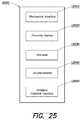
- an equipment sensorcomprising: a mechanical interface configured to attach the equipment sensor to a piece of equipment; a proximity sensor configured to detect a presence of an operator within a range of the piece of equipment; at least one altimeter adapted to detect an altitude of the piece of equipment; at least one accelerometer adapted to detect motion of the piece of equipment; and a wireless network interface adapted to communicate data to an external system, the data comprising at least one of a group of information including: the altitude of the piece of equipment; the presence of the operator of the piece of equipment; and the motion of the piece of equipment.
- FIG. 1shows a block diagram of a distributed computer system capable of implementing various aspects of the present invention
- FIG. 2shows an example check-in station according to one embodiment of the present invention
- FIG. 3shows an example sensor architecture according to one embodiment of the present invention
- FIG. 4shows example event management functions that the system according to various embodiments of the present invention may perform
- FIG. 5shows an example process for managing sensor devices and workplace events according to one embodiment of the present invention
- FIG. 6shows another example process for operating sensors in a mesh network according various aspects of the present invention
- FIG. 7shows an example process for admitting a sensor to a mesh network according to various aspects of the present invention
- FIG. 8Ashows an example message format according to various aspects of the present invention
- FIG. 8Bshows an example admin block message according to various aspects of the present invention.
- FIG. 8Cshows an example beacon block message according to various aspects of the present invention.
- FIG. 8Dshows an example router block message according to various aspects of the present invention.
- FIG. 8Eshows an example SIM block message according to various aspects of the present invention.
- FIG. 8Fshows an example status relay block message according to various aspects of the present invention.
- FIG. 8Gshows an example even block message according to various aspects of the present invention.
- FIG. 9shows an example mesh network configuration according to various aspects of the present invention.
- FIG. 10shows another example mesh network configuration according to various aspects of the present invention.
- FIGS. 11A-11Bshow several views of a sensor device according to various aspects of the present invention.
- FIGS. 12A-12Cshow additional views of a sensor device according to various aspects of the present invention.
- FIGS. 13-24show several management interfaces according to various aspects of the present invention.
- FIG. 25shows an embodiment of an equipment sensor according to various embodiments of the present invention.
- FIG. 26shows an example system in which the equipment sensor may be used.
- a systemis provided that is capable of monitoring subjects and equipment throughout the workplace.
- the systemmay include a monitor having various sensing capabilities that may be assigned to a monitored subject, the monitor being capable of recording various parameters that are personal to the worker.
- a sensorthat can be attached to the monitored subject (e.g., at the belt line) that is adapted to monitor certain parameters associated with the worker's environment.
- the belt line of a workermay be beneficial for monitoring the location of the worker, detecting accurately slip, fall, and other events, and avoiding false events.
- a sensor assigned to the monitored subjectmay be capable of determining the location of the subject, along with motion, impacts, altitude, and other environmental parameters that could affect the health or other condition of the worker. Further, it is appreciated that it may be helpful to record and visualize various information from individual or a collection of workers that are obtained through the monitoring function.
- the systemmay include an equipment monitor having various sensing capabilities that may be assigned to a piece of equipment, the equipment monitor being capable of recording various parameters associated with the piece of equipment.
- the equipment monitormay be attached to the piece of equipment and may monitor certain parameters associated with the piece of equipment's environment.
- the equipment monitormay be capable of determining the location of the piece of equipment, along with motion, altitude, and other parameters that may affect the state or condition of the piece of equipment.
- the equipment monitormay be capable of analyzing these parameters using a set of programmable coefficients and thresholds to determine the operating mode or state of a particular type of equipment.
- the equipment monitormay be located on the piece of equipment in a location such that the equipment monitor may determine if an operator is present at the piece of equipment.
- the equipment monitormay emit a Radio Frequency signal which may be receiver by a sensor worn by a worker such that the worker's sensor can determine relative proximity to the equipment sensor. Further, it is appreciated that it may be helpful to record and visualize various information from individual or a collection of pieces of equipment that are obtained through the monitoring function.
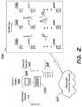
- FIG. 1shows a block diagram of a distributed computer system 103 capable of implementing various aspects of the present invention.
- distributed system 103includes one or more end systems 104 , one or more nodes (e.g., nodes 102 A- 102 D) configured in a wireless network, and one or more sensors assigned to monitored subjects (e.g., monitored subject 101 ). Some or all of these entities may be coupled through a one or more communication networks, such as by a wireless network, the Internet, and the like.
- End systems 104may include, for example, a desktop computer system, mobile device, tablet or any other computer system having a display.
- various aspects of the present inventionrelate to interfaces through which the user can interact with a management system (e.g., management system 101 ) to monitor subjects and equipment and perform management functions using their monitored data.
- a client applicationmay be provided that may include one or more interfaces through which management users access the distributed computer system 103 .
- Other applicationsmay be provided that permit management users to assign sensors to monitored subjects and equipment at the worksite, and to retrieve and reassign sensors after a particular monitored subject has left the worksite or a piece of equipment is no longer in use.
- Some system aspectsrelate to monitoring workers and equipment that travel from one site to another as well.
- sensor dataincluding events, indications of the location of an event, the time at which an event occurred, and any parameters associated with that event may be communicated through a communication network to the distributed computer system (e.g. computer system 103 ).
- a logical locatione.g., a specific room on a specific floor of a building
- the communication networkmay be a wireless network that is configured and arranged on a particular worksite (e.g., worksite 100 ).
- the wireless networkmay be constructed of a number of wireless nodes (e.g., nodes 102 A- 102 D) that communicate together to form a mesh-type network.
- a sensor associated with a monitored subject or piece of equipmentmay experience certain environmental parameters within the workplace, and may store events within a memory of the sensor device.
- the sensorperiodically communicates with a computer system (e.g., distributed computer system 103 ) to transfer event messages.
- a computer systeme.g., distributed computer system 103
- event messagesmay be received and stored within one or more storage elements of the distributed computer system.
- Information associated with those eventsmay be presented, for example, within a management interface, within an event message sent to management users, and/or sent to one or more external systems (e.g., a resource planning system).
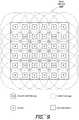
- FIG. 2shows an example check-in station (e.g. check-in station 202 ) according to one embodiment of the present invention.
- a check-in stationmay be provided that permits one or more check-in operators (e.g., operator 205 ) to associate monitored subjects (e.g., monitored subject 201 ) with respective sensors (e.g., sensors 206 ).
- check in station 202may include one or more computer systems (e.g., system 204 ) having one or more management interfaces that allow the check-in operator to associate a sensor with a monitored subject.
- system 204includes a reader/interface 203 that has the capability of identifying sensors individually during the check-in process. For instance, reader/interface 203 may identify a sensor using RFID.
- System 204may also be capable of identifying a monitored subject 201 at the worksite (e.g., worksite 200 ).
- the monitored subjectmay have one or more user identifications that can be read by one or more systems (e.g., system 204 ).
- an operator usermay scan an ID of a subject or perform any other method for identifying the subject (e.g., receive biometric data, view a picture of the subject and visually identify him/her, or the like) and by scanning a sensor using a computer system at the checkpoint, the computer system associates the monitored subject with a particular sensor.
- a record identifying that particular monitored subjectto be stored within the memory of the distributed computer system (e.g., distributed computer system 207 ). Thereafter, the system may monitor events and other parameters associated with the assigned sensor as the monitored subject operates within the monitored worksite.
- a wireless communication networkmay be configured on the worksite including one or more nodes (e.g., nodes 208 A- 208 ZZ) that are interconnected within a mesh network.
- Monitored subjectse.g., monitored subject 101
- the monitored worksitee.g., worksite 200
- the sensorscommunicate over the mesh network by communicating with one or more nodes which relay the messages to the distributed computer system (e.g., computer system 207 ).
- Distributed computer system 207may include one or more management interfaces used for the purpose of monitoring users, events, and their associated data.
- the systemis capable of supporting a worker or piece of equipment traveling between sites.
- the sensormay, according to one implementation, be capable of identifying and joining a mesh network at any one of multiple geographically distinct locations. Upon joining any network, all of the features of the sensor will be available, along with identification of the site's network to which the sensor is connected.
- the systemmay be associated (e.g., using a management system) to associate the sensor with multiple mesh networks, and when the sensor comes within a communication range of the network, the sensor automatically joins the network. This may be useful, for example, for a supervisory worker or other role that requires visits to multiple locations.
- the systemis capable of supporting a worker or piece of equipment traveling between sites wherein events may be locally stored within the sensor along with location data.
- the sensormay, according to one implementation, be capable of storing alerts detected when not connected to the mesh network, or alternatively, transmitting them through an alternate network (e.g., cell phone network, Bluetooth, or other communication capability).
- the sensormay also be configured to transition to an unconnected mode when not in range of the mesh network (or any other network).
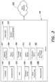
- FIG. 3shows one embodiment of a sensor device according to various embodiments of the present invention.
- sensor 300may include one or more components including a processing component that includes, but is not limited to, a controller 301 that is capable of processing data.
- Controller 301may be, for example, a microprocessor, microcontroller or other processing entity that is capable of receiving event data, performing analyses of the data, and communicating information over one or more communication interfaces.
- Componentsmay be coupled to the controller internal to the sensor using one or more connections, circuits, busses or other connection elements.
- Device 300may also include one or more sensing elements, such as accelerometers (e.g., accelerometer 302 ), gyros (e.g. Gyro 303 ), pressure sensors (e.g., pressure sensor 304 ), magnetometers (e.g., magnetometer 306 ), or any other detector type (e.g., other detectors 311 (e.g., temperature)).
- device 300may be RFID capable, and to this end, device 300 may include an RFID transponder (e.g. transponder 305 ). When scanned, the RFID transponder may provide an identifier of the particular sensor device (e.g., device 300 ).
- the RFID transponder or tagmay be an active tag, a passive tag, battery-assisted passive tag, or other implementation.
- the RFID functioncan be implemented in conjunction with or separate from other sensor functions.
- RFID capabilitymay be built in to one or more of the mesh network nodes, and a control on the node may be provided that permits a sensor to be admitted to the network without a separate computer system (e.g., at a check-in location). In such a case, the network node, after scanning the RFID of the sensor, sends a message over an administration channel to admit the sensor to the network.
- Device 300may also include one or more network interfaces (e.g., network interface 307 ) through which the sensor device communicates information to other systems.
- sensor device 300may also include one or more antennas 310 that permit the sensor to communicate wirelessly to one or more mesh nodes within the mesh network (e.g., mesh network 312 ).
- System 300may also include a power source 308 , such as a battery. In one model implementation, the system is architected to minimize the amount of power drawn on the battery such that the sensors need not be recharged at the worksite.
- sensor 300includes a proximity sensor 309 that is used to determine whether or not the sensor is being worn by an actual human subject. For instance, in a situation involving fraud, a sensor may be purposefully dropped, thrown, or tied to some other object that experiences certain environmental conditions. To avoid false alarms, workplace fraud, and other indications not involving the assigned monitored subject, system 300 may have a proximity sensor that is capable of nullifying an alert, or otherwise qualifying information that may be provided by the sensor. Such a proximity sensor may include, for example, one or more detection elements such as an IR or capacitive proximity sensing element as known in the art. In certain cases, it may be beneficial to place the sensor device in a low power mode until the sensor is actually attached to a user in the prescribed manner and to eliminate false indications and reporting.
- a proximity sensor 309that is used to determine whether or not the sensor is being worn by an actual human subject. For instance, in a situation involving fraud, a sensor may be purposefully dropped, thrown, or tied to some other object that experiences certain environmental conditions. To
- sensor 300may include a switch integrated into the sensor that detects when the sensor is attached to the user.
- the switchis incorporated within a clip of the sensor (e.g., switch sensor 313 ) that attaches the sensor to the user.
- the switchis configured to provide an indication when the clip is attached to something.
- Such a switchcan be used for power saving, as the sensor may be transformed to a low-power mode when the clip is not attached. Further the use of the switch may be recorded, and can be used for fraud prevention, such as the case when a fall is detected. For instance, if the device is unclipped immediately before an event, it raises questions about the authenticity of that event.
- the senoris capable of detecting and recording detachments of 100 milliseconds or more, so that when the device is moved from one person (e.g., to another person or object), the removal is detected and recorded. For instance, even if the sensor is quickly removed for one person to another, or from a person to an object, the device may store an event in the sensor and/or communicate that event to the system (e.g., a supervisor, management system, etc.) via a message sent on the mesh network.
- the systeme.g., a supervisor, management system, etc.
- the senormay include a switch (e.g., pushbutton switch 314 ) that permit the user/wearer to perform a manual alert.
- the usermay push a button on the sensor to alert others of a safety issue.
- a button on the sensormay alert others of a safety issue.
- an activation of the buttoncould indicate a witnessed safety violation, an emergency condition, or other workplace situation.
- certain button selection patternsmay be used by the user to create different types of manual alerts. For instance, a single press may be a safety alert, a triple press may be an emergency situation, among others.
- the senormay include a speaker, sound module, transducer, or other type of sound generating component to generate audio alerts.
- the sound-generating componentmay be configured to generate sounds upon certain conditions (e.g., pressing of a pushbutton, making a chirp sound, etc.).
- Other capabilitiesmay be provided by similar sound-generating component, such as providing a centralized evacuation alert, where an action taken by a supervisor or computer system can cause all sensors on a site or sublocation to start alarming.
- the systemmay be configured to allow for a supervisor's sensor to make an audible alert when any worker experiences an event.
- the supervisormay check their sensor or other computer system (e.g., a mobile device) for details regarding the event.
- a visual (e.g., LED) and/or audio alertthe wearer may use a feedback component such as a push button to acknowledge an event and communicate information to the system.
- the sensormay include an LED indicator when a push button is pressed.
- the LEDmay be configured to indicate a different color/pattern when the alert has been acknowledged.
- a messagemay be sent to the sensor if acknowledged, indicating to the wearer that help is on the way.
- the sensormay be configured to provide an alert acknowledgement that is audible as well. It should be appreciated that one or more statuses of an alert may correspond to one or more indicators, or indicator combinations.
- the sensormay include a pressure sensor (e.g., pressure sensor 304 ) used to assist in determining the altitude of the sensor.
- a pressure sensore.g., pressure sensor 304
- the wearer's altitudemay be determined by comparing the barometric pressure as measured by the wearer's sensor with pressure measured by one or more nearby mesh network nodes.
- the altitude of particular network nodesis a known entity (e.g., they can be determined a priori and may be stored in memory of the node devices). Such information may be determined a priori during installation, or may be determined using a pressure detection element located within a network node (e.g., within a router).
- These known heightsmay be used to determine what floor of a structure the user is located using a table (or other date structure) including heights for each floor, the data being stored in a database accessible through a communication network.
- An absolute altitudemay be determined by comparing the sensor's pressure measurement to the values stored in the database. Once an altitude is determined, a floor of a particular structure may be determined based on a comparison with the pressure values of the known node devices. Once a floor is determined, possible regions/zones may be determined on that floor using relative signal strengths to mesh nodes. By using both altitude and relative signal strengths, a more accurate location within the worksite may be determined.
- the senormay include a low-power microcontroller.
- a microcontrollermay include one or more radios (e.g., a radio operating in the 900 MHz band).
- the sensormay include a 6-axis MEMS accelerometer and gyroscope to perform detection of events.
- the sensormay include other components, such as, for example, rechargeable batteries, barometric sensor, a capacitive proximity sensor, RFID transponder, among others.
- FIG. 4shows example event management functions that the system according to various embodiments of the present invention may perform.
- the sensormay determine whether an event occurred, along with parameters associated with that event. For instance, the sensor may indicate the location of the event. This may be determined, for example, by determination that a particular sensor is within range of a particular router node. Location may also be interpolated based on relative signal strength received from one or more router nodes. Location may also be determined through triangulation or some other method. It may be useful to have real-time alerts for certain accident types that includes location information, as emergency personnel may be dispatched to the identified location in less time. To this end, the system may also be configured to communicate with emergency systems (e.g., a 911 system) for the purpose of receiving emergency service in a more expedited manner.
- emergency systemse.g., a 911 system
- the sensormay also be capable of determining how high and how hard a particular fall was associated with an event.
- the sensormay be capable of determining the type of fall (e.g., forward, backward, number of rotations or altitude during the fall, etc.) based on parameters detected by the accelerometers and/or gyroscopic devices within the sensor.
- the sensormay also be capable of determining whether the sensor is being worn properly or at all at the time an event occurred. Such an indication may be used to eliminate false signals and/or alerting, or may be used to qualify (or disqualify) a particular reading or event.
- the sensormay include a memory element that stores event data, along with a time at which the event occurred.
- Time informationmay be generated, for example, by a controller, and the controller may receive time indications from a centralized system (such that all sensors have the same or similar absolute time setting). Time settings may periodically be sent by system elements to synchronize time settings among the components and sensors. Sensors may also receive a centralized time setting upon admission to the network.
- each sensoris associated with a particular monitored subject, and this association may be used to identify the subject that experiences the workplace condition and/or generally monitor the subject.
- a secondary function of the systemmay include performing compliance and identification functions. For instance, it may be helpful to have a system that can verify whether the subject being monitored is actually at the jobsite, during the time that the subject is expected there. The system may also be helpful in performing a geofence function with certain areas of the jobsite. For example, there may be locations that have a certain level of security, have a dangerous condition, need a certain level of training, etc. and having a system that can track the location of users and alert on entry of the monitored subject to such locations would be advantageous.
- the systemmay include a management interface through which one or more geofence areas may be defined and/or monitored. Further, there may be a need to simply monitor locations of subjects at the workplace, and the system may be capable of providing this function. Further, because the system is capable of determining what workers are (or are not) on a particular jobsite, the system may also be used in the case of a sitewide emergency response where workers need to be accounted for, along with their locations.
- Yet another set of functions the system could performrelates to resource management and tracking. For instance, it would be beneficial to be able to track and identify certain resources (e.g., roles such as a plumber) at particular job locations and to automatically record their presence there.
- the systemcould send updated reports and/or alerts when particular parameters are triggered (e.g., exceeding the amount of allocated hours for plumbers for a particular job and/or job location in a defined period).
- Such informationmay be communicated to other systems, such as resource management systems, that provide tracking and budgeting functions for a particular job. For instance, a resource management system can measure the number of hours plumbers are located on a particular job, and can compare this measurement to a budgeted amount for a particular task.
- the resource management systemmay be configured to provide alerts and/or reports based on such information.
- FIG. 5shows an example process 500 for managing sensor devices and workplace events according to one embodiment of the present invention.
- process 500begins.
- the sensoris scanned at a check-in station as discussed above.
- a computer system assigned to a check-in station having a reader devicecan be used to identify a particular sensor (e.g., using an RFID reader).
- the systemassigns the sensor to a monitored subject.
- the workermay have some identification information (e.g., an ID badge) that can be scanned at the check-in site, and that can be associated with an assigned sensor.
- the senormay be connected to the mesh network or otherwise admitted to the communication network.
- a communication protocolmay be used to assign the sensor to the network.
- the networkassigns the sensor to a particular timeslot for transmission of event data.
- the sensormay need other communication information, such as site identification information, radio channels being used at the site, network topology information, among other site communication information. Such information may be provided to the sensor by one or more nodes of the network, the site information being formatted within an administrative message communicated to the sensor over an administration channel.
- the systemmonitors the sensor for events at block 505 .
- the sensortransmits events generated within a predefined period during its assigned timeslot.
- the sensortransmits events to the management system.
- the systemmay alert the user (e.g., at block 507 ) of particular events received from a particular sensor.
- the monitoring processis continually performed, with sensors being admitted and removed from the network in real-time.
- FIG. 6shows another example process 600 for operating sensors in a mesh network according various aspects of the present invention.
- process 600begins.
- systemscans a monitored subject identification at a check-in location. For instance, a computer system at the check-in site be used to scan and ID badge or other identification from the monitored subject.
- Block 603the system scans the sensor at the check-in site, by reading, for example an RFID tag associated with the sensor.
- the system assigned to sensor to the monitored subject within the databaseis assigned to sensor to the monitored subject within the database.
- the monitored subjectenters the worksite.
- the systemadmits the sensor to the mesh network and monitors the sensor for the occurrence of events.
- a management systempassively receives event and other status information from one or more sensor devices.
- the monitored subjectmay deposit the sensor in a receptacle at the worksite, and the sensor may then be disassociated with the monitored subject. Thereafter, the sensor may be reassigned to another monitored subject. Alternatively, the monitored subject may leave the worksite and retain the sensor. The sensor, after leaving the worksite and being out of range of the network may enter a power down mode (e.g., after a predetermined amount of time) at block 609 . If temporarily out of range of the network, the sensor may still record event data for a predetermined amount of time, and may transmit the information when the sensor is readmitted to the network. At block 610 , the monitored subject may return to the worksite and may come into range of the mesh network. The sensor may then enter a power-up mode and may be admitted to the network. At block 611 , process 600 ends.
- a power down modee.g., after a predetermined amount of time
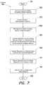
- FIG. 7shows an example process 700 for admitting a sensor to a mesh network according to various aspects of the present invention.
- one aspect of the present inventionrelates to a process for admitting sensors to the mesh network.
- process 700begins.
- the senoris positioned within proximity of the mesh network.
- the systemuses a special administrative channel to perform administrative functions with sensors, and uses the administrative channel to facilitate sensors joining the network.
- a sensor that has not yet joined the networkmonitors and administrative channel.
- the management systemassigns the sensor to the mesh network. This may be performed, for example, responsive to a computer system at a check-in point making an association between the sensor and a particular monitored subject (e.g., as an association between an ID badge and a sensor ID).
- an access point notesends a pairing request packet on the administrative channel indicating the sensor to be admitted to the mesh network (e.g., block 705 ).
- the administrative channelis operated at a low power setting in relation to general data transmission channels so that signals will not interfere between other nodes in the network.
- the signalis operated at a level that nearby sensors are able to receive the signal and be admitted to the network.
- operating the administrative channel frequency at a relatively low powerpermits multiple check-in sites to be operated relatively close to one another.
- the pairing request packetmay include information identifying the sensor such as a serial number, network identifier, or other indicator.
- the pairing requestmay also include information that identifies a communication slot assigned to the sensor that uniquely identifies the slot in which a particular sensor sends status messages. For instance, the pairing request may include an indication of a time offset from the start of a communication cycle.
- the pairing requestmay send other information such as timestamp information (e.g., to provide a system time setting for synchronization purposes), a common channel for communicating in the particular mesh network.
- the sensorresponds on the administrative channel with an acknowledgement message indicating that the particular sensor has received its configuration.
- the sensorsynchronizes with the network communication cycle, and begins communicating with the mesh network at block 708 , periodically sending status messages within its assigned timeslot.
- process 700ends.
- a protocolmay be provided for communicating between nodes and sensors for monitored subjects and pieces of equipment.
- an RF wireless communication protocolis provided that includes a hybrid time-division/cellular approach to facilitating communication between a large number of sensors in a sensor network and a cloud-based server.
- the term cellularrefers to the fact that the network is organized into cells, not a cellular telephone network such has 3G or LTE, although it should be appreciated that any type of network may be used.
- the network protocolmay be implemented as a specialized protocol operating over multiple channels in the 900 MHz ISM band.
- the protocolutilizes a Time Division Multiple Access (TDMA) scheme wherein each transmitter has specific time slots in which it is allowed to transmit. This arrangement allows large numbers of transmitters to share a single channel without interfering with each other.
- TDMATime Division Multiple Access
- the network protocolalso may be based around a periodic cycle.
- This cyclecan be nominally 10 seconds in one implementation, but could be longer or shorter depending on the requirements for number of transmitters and maximum latency.
- the cyclemay be further broken up into blocks, each of which provides a specific function to the system. Because, according to one embodiment, the sensors have information in advance when they need to receive beacons, they can keep their radios turned off much of the time, resulting in very low power consumption.
- Nodes in the networkcan be three primary types:
- Coordinator/GatewayCoordinates communication activity within a cell and routes data from nodes in that cell to the cloud server (e.g., via the Internet). These nodes are powered externally and have some form of network connectivity (e.g., Internet).
- One coordinator in the networkis designated the master and drives the timing for the entire network.
- Routercan be used as most of the fixed-position nodes in the sensor network.
- router nodesare responsible for providing the mobile nodes with location data and relaying data to the Gateway nodes. Routers are placed within communication range of a Coordinator/Gateway. In one implementation, router nodes are capable of being battery-powered, allowing for easy deployment.
- router nodesinclude the sensors. According to various embodiments, these sensors are worn by personnel, and attached to pieces of equipment, moving around the job site. They report status, location, and events to the nearest router or gateway node.
- the nearest router or gateway nodemay be determined, for example, by comparing values of Received Signal Strength Indication (RSSI) as measured from the perspective of each sensor.
- RSSIReceived Signal Strength Indication
- the nearest router or gateway nodemay be selected as the entity with the highest value of RSSI.
- systemmay implement the following specifications:
- the protocolis based on a time-division scheme using a 10-second cycle.
- This cycleis broken up into blocks, each of which has a specific purpose and is further broken into timeslots.
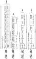
- FIG. 8Ashows blocks within the 10-second cycle, and as shown, the cycle is broken into alternating Normal Blocks and Admin Blocks.
- Normal blocksare used for most of the functions of the system, and are transmitted on the operating channel selected for the site.
- Normal Blocks 800are 950 ms long.
- Admin Blocksare used for pairing of SIMs, always transmitted on channel 0, and are 50 ms long.
- blockreserves a 10 ms window at the end for changing channels.
- the networkuses multiple channels to allow adjacent cells to operate independently while allowing mobile nodes to move between cells seamlessly.
- the following channelsare assigned:
- Admin Channelthis is hardcoded (e.g., to a designated channel such as channel 0), and is used only for pairing SIMs with the network.
- the admin channelmay be used at reduced signal strength to prevent interference with other nearby deployments.
- Common ChannelThis is the channel used by all nodes in the network during the Beacon, Router and SIM blocks. This channel may be assigned to the network during deployment, and passed to the SIMs during pairing.
- Cell ChannelEach cell is assigned a channel such that no two adjacent cells have the same channel. Some cells may use the Common Channel as their Cell channel. For example, according to one implementation, a network with square cells would need four (4) cell channels to operate, and a network with hexagonal cells would require three (3) cell channel. Packet Header
- each packet sent in a timeslotcontains a standard header comprising the following fields:
- destination ID informationis not part of the header, as many of the packets in the system are considered to be broadcast. Certain packet types may add a destination ID, however.
- each packetcontains a 2-byte CRC.
- a sensore.g., a SIM
- the SIMstarts listening continuously on channel 0.
- the normal processincludes scanning the SIM at the Gate Station, and which causes the AP to send a pairing request packet in the next admin block.
- the pairing requestcontains the following:
- the SIMresponds with an acknowledgment, and then synchronizes to the communication cycle (using the time offset in the pairing request) and begins transmitting during its SIM timeslot.
- An example implementation of an admin block 810is shown in FIG. 8B .
- the admin blockcontains timeslots for two pairs of pairing requests/responses. Both the request and response have room for up to 45 bytes.
- the admin channel 0 communicationis performed at a reduced power level, and that no two gates are within range of each other to cause interference.
- the Beacon Blocksupports the following functions:
- the beaconutilizes very short packets to minimize the amount of time the SIM needs to have its receiver active.
- Each packetcomprises the following information:
- the SIMslisten to the beacon block to determine the closest router. Once the closest router is located, the SIM needs only to listen for beacons from that router and its neighbors. The list of neighbors and other information about the router is determined by listening to the router block.
- the Router Blockallows SIMs to gather information about network topology which is required for efficient use of the network.
- FIG. 8Dshows one example implementation of the Router Block 830 .
- the blockis divided into timeslots for up to 180 Router or Gateway Nodes.
- each routertransmits information regarding the topology of the network:
- the timeslotsallow for 1 millisecond of “dead air” between timeslots of different transmitting devices to allow for jitter. This feature may be consistently implemented throughout the protocol.
- a master routere.g. Router 1
- Routersshould use the timing information from the router with the lowest master distance they receive from to allow propagation through the network.
- FIG. 8Eshows the timeslot division of the SIM Block 840 .
- the SIM packetsare short (up to 20 bytes). The following information is contained in each:
- a Status Relay Blockallows each of the router nodes in a cell to relay SIM status and routing information to the cell's Coordinator node.
- the Coordinatorfirst sends a packet containing any commands for the routers.
- the commandmay include commands that control the routers to change network organization (e.g. join a different cell) or power down for a period of time, or perform other functions.
- each Router in the celltransmits a packet in its designated timeslot containing its own status and the SIM statuses it has received in the current cycle:
- the coordinatorhas (e.g., stored in memory) the current status and event count for all SIMs within the cell, which it can then use to allocate timeslots and routing for the Event Block.
- the communication cyclecontains 4 event blocks, each of which can hold 6 events.
- eventsgenerally require two hops to make it to the Gateway, so this arrangement provides for a sustained rate of 1.2 events per second within each cell.
- FIG. 8Gshows an example breakdown of an Event Block 860 according to one implementation.
- the first portion of the Event Blockis dedicated to routing, where the event timeslots are allocated to SIMs and Routers in such a way to allow event packets to be relayed to the Gateway.
- First the Coordinatorsends a routing packet, which is then repeated by each of the routers so that all nodes get the information.
- the routing packetcomprises a Message ID, Source ID, and Destination ID for each of the six (6) event timeslots. This information indicates to the nodes in the system when they should be receiving and transmitting to relay event packets from SIM to Gateway.
- the next portion of the Event Blockis the event timeslots.
- each event timeslothas room for a 680 byte payload. This is sufficient, for example, to handle 100 samples on each of the accelerometer and gyro axes, forty (40) samples from the altimeter, plus additional timestamp, initial conditions, location, and status information.
- the final portion of the Event Blockis the ACK timeslots, in one implementation.
- each ACK timeslotcontains flags for the acknowledgment of events that were transmitted.
- the coordinatorsends its ACKs, and then each of the routers relay these ACKs to all SIMs in the cell.
- This blockprovides significant room for expansion as the block allows routing of arbitrary packets between nodes within a cell. For instance, this may be used for initial autoprovisioning of the network, reconfiguration of the nodes, and/or support of new sensor types.
- FIGS. 9 and 10show example implementations of possible matrixes of router nodes and coordinator/gateway devices in one or more mesh networks (e.g., mesh networks 900 and 1000 ).
- FIG. 9shows a network organization of a mesh network 900 using four cells in a square-grid layout. This layout could cover, for example, over 2 million square feet using four (4) Gateways and thirty-two (32) Routers.
- FIG. 10shows a hexagonal arrangement of cells in a mesh network 1000 . This arrangement covers area more efficiently than a square grid and requires one fewer channels to operate, however, this arrangement may be more difficult to deploy and provision.
- the SIMmay be required to have the receiver active during the Beacon Block, and to transmit during its designated timeslot in the SIM block.
- the SIMcan typically monitor at most nine (9) of the timeslots, corresponding to the closest node from the previous cycle and up to eight (8) of its neighbors. This represents 18 milliseconds out of a 10 second cycle, or a 0.18% duty cycle. Transmission in the SIM block is a short 4 ms packet once per 10 s cycle, or a 0.04% duty cycle.
- the SIMcan perform the following with the radio:
- each eventadds 53 ms of RX time and 136 ms or TX time. If 100 events are expected over an 8-hour shift (most of these false events filtered by cloud), this results in an additional 0.02% RX duty cycle and 0.05% TX duty cycle.
- the SIMmoves within range of a router for the first time, the SIM listens to the corresponding packet in the router block, which is a rare occurrence in most example deployments.
- an eventis analyzed to determine whether the event represents a real fall or other type of event.
- a basic version of this analysisis performed within the sensor, in order to reduce network bandwidth utilized sending false events.
- the analysis of an eventmay include one or more of the following components:
- Freefall durationIn a simple freefall, the duration in freefall can be used to compute the height of the fall using:
- h1 2 ⁇ at 2 where h is the fall height in meters, t is the duration of freefall in seconds, and a is the acceleration of gravity (9.8 m/s ⁇ circumflex over ( ) ⁇ 2)
- Jump Detectionit is appreciated that the above equation used to determine freefall duration may not provide accurate results in the case of a jump, where the user accelerated upwards at the start of the freefall duration. To account for this, the pre-trigger accelerometer data is examined for a jump. This can be represented as an upward acceleration immediately prior to the freefall. Through discrete integration the upward velocity can be approximated, and used in the modified equation:
- his the fall height in meters
- v0is the initial upwards velocity
- tis the duration of freefall in seconds
- ais the acceleration of gravity (9.8 m/s ⁇ circumflex over ( ) ⁇ 2)
- the altimeter datacan be correlated with the fall height computed above to provide a more accurate estimate of fall height and higher confidence in the legitimacy of the event.
- the acceleration at the end of freefallcan be examined to determine whether the subject experienced a hard or soft landing. This can be used to help determine whether the fall was intentional (such as hopping down from the bed of a truck) or unintentional.
- the severity of the landingcan be recorded with the event in the cloud database, and events with severity below some threshold will be hidden from reports by default (e.g., to lessen the number of false reports).
- the systemmay be capable of detecting and reporting false events.
- Probable Sensor ThrowThese events occur when a user throws a sensor up in the air, either catching it or letting it fall. In one embodiment, these events are characterized by a high acceleration immediately prior to the period of freefall. This acceleration is greater than if the user jumps or falls during a genuine event, and can be used to discriminate this event type from other event types. The system compares the average magnitude of the acceleration vector during a period (for instance, 0.4 seconds) immediately before freefall, and if this acceleration exceeds a pre-set threshold (2.4 g) the event is marked as a probable sensor throw.
- a pre-set threshold2.4 g
- Probable Sensor DropThese events occur, for example, when the user drops their sensor, or the sensor is knocked off their belt and falls to the ground. These events are characterized by a high rate of rotation upon impact, followed by a period of no rotation as the unit sits at rest on the ground.
- the algorithmis only applied to falls that have a measured height of less than a predetermined height (e.g., 2 meters).
- the systemmay be configured to identify the peak angular velocity during the period starting when the device is in freefall through a predetermined time (e.g., 1 second) after the end of freefall.
- the systemchecks for inactivity by calculating the RMS angular velocity during a period after impact. If the RMS angular velocity is below a set threshold (e.g., 5 degrees per second) then the device is assumed to be at rest, and the event is marked as a probable sensor drop. Input from the proximity or clip sensor may be used to increase the confidence of this filter function.
- a set thresholde.g. 800 degrees per second
- the systemis able to determine the approximate location of each sensor by comparing the signal strength between the sensor and each node in the mesh network (e.g., via measurement of RSSI), and interpolating the position between the nodes.
- the sensorrecords the received signal strength of each Beacon packet and returns this information in its status packet.
- the Gateway and Relay nodesalso record the received signal strength from each sensor, and send this information along to a management system (e.g., an application program executing on one or more server systems in a cloud-based environment (referred to herein as the “Cloud server”).
- the Cloud servercan combine the signal strengths for a more accurate estimate of the distance between the sensor and each node.
- buildingscan be complex environments for tracking location in this way, as structures can both block and reflect radio waves.
- Several strategiescan be used to improve location accuracy:
- the pedometer function of the accelerometercan be utilized to estimate the distance a user has walked in a given period of time, further improving the filtering that can be performed.
- Calibration mapFor fixed installations, part of the deployment can be mapping signal strengths across the job site, which can then be used to provide much more accurate location measurements. For instance, in one application, a signal from the altimeter is used as an input to determine which floor a user or piece of equipment is on, and then responsive to the floor determination, a calibration map may be selected that is linked to the particular floor. Calibration maps may be determined when the system is first installed, and may associate actual logical locations (e.g., via a map or other locational construct) with a pattern of RSSI values from multiple mesh nodes.
- a usermay try to simulate a slip or fall in order to fake an injury. In most cases, this will require taking the sensor off the body.
- the proximity sensor or clip-based switch in the devicewill detect that the sensor is not being worn, and any events that occur while not worn is disregarded.
- the proximity sensorhas the ability to discriminate between an animate object (such as a human body) and most inanimate materials, such as wood and stone. In this way, for example if a user takes off his sensor and attaches it to a sack of concrete and then pushes it off the back of the truck, the system will know that this was not a real fall. Further, the system will contain a record of the attempted fraud, so that appropriate action may be taken.
- a usermay want to bypass the location tracking of the sensor by taking it off. If the user takes off the sensor and leaves it somewhere, according to one embodiment, the system detect it is not being worn (via, for example, the proximity sensor and/or clip switch) and that it is not moving (via the accelerometer) and the sensor may alert the supervisor or other system. If a user tries to bypass the system by having another user wear his sensor (in addition to that user's own sensor), this situation may be more difficult to detect.
- the systemmay be adapted to run correlations on the position and motion of the sensors to detect if a single individual is wearing more than one sensor. In this case, an alert can be generated and sent to the supervisor.
- gateway nodescan be outfitted with an RFID scanner capable of scanning both the sensors as well as standard RFID access cards or tokens.
- an RFID scannercapable of scanning both the sensors as well as standard RFID access cards or tokens.
- the userwill first scan his badge, then take a sensor and scan the sensor as well. This capability allows the system to associate that sensor with a particular user or piece of equipment.
- the userWhen leaving the site, the user just scans his badge, and deposits the sensor in a receptacle. The system may then automatically disassociate the user from the sensor.
- access cardsmay be replaced with keychain fobs or stickers placed on hardhats or other gear, with the rest of the operation staying the same.
- the systemmay be adapted to automatically register the user when a user has come within range of the mesh network and mark them as having arrived on site. When the sensor leaves range of the mesh network for a specified duration, the user is marked as having left the site.
- the above situationmay work optimally when the site is fully covered by the mesh network.
- the sitehas “blind spots” not covered by the network, it may be necessary for users to badge in and out. In this case, the users can scan their badges, and not their sensors.
- the senorTo function within the mesh network at a specific site, the sensor requires configuration information regarding the site, such as site identification, radio channels being utilized, network topology, etc. This information is collectively called the “site configuration.”
- the systemcontains a mechanism for automatically associating sensors with the network such that a new sensor from the factory can be utilized at any job site with no manual configuration.
- gateway nodesperiodically transmit on a fixed frequency, known as the “admin channel”. These transmissions are performed at a reduced signal strength, so that only nearby sensors can receive it and so that the signals do not interfere with other gateway nodes in the network.
- These admin transmissionscontain the site configuration required for a sensor to find the mesh network. Further, packets targeting a specific sensor may be sent on the admin channel, containing sensor-specific configuration such as protocol timeslot assignments. This may be done following a scan of the sensor's RFID tag or automatically upon detection of a new sensor.
- the sensor device that worn the beltline by a particular subjectmay have one or more attachments that are used to affix sensor to the monitored subject.
- FIGS. 11A and 11Bshow varies embodiments of a sensor 1100 that may be used to monitor a particular subject.
- Sensor 1100include, for example, a clip 1101 that attaches sensor 1100 to the user.
- Clip 1101may include an internal mechanism that, when clipped to the user, a switch is activated. The switch may be used alone or in conjunction with other sensors (e.g., a proximity sensor) to determine whether the sensor is coupled to the user.
- the sensor 1100may also include a button 1102 that is used by the user to initiate manual alerts. The sensor may be responsive to one or more different patterns of button presses to indicate different types of alerts.
- FIGS. 12A-12Cshow different perspective views of an example sensor 1100 that may be used by the system in accordance with various embodiments.
- a gateway nodemay be configured to send all events, statuses and scan operations to the Cloud server by utilizing web services.
- the Cloud servermay include logic that decodes the events, status and scan operations and store the appropriate decoded information, along with the source into its database for further processing and for display to the user via one or more user interfaces (e.g., a Cloud Dashboard).
- the Cloud server systemmay be accessible by one or more user types through one or more networks.
- the Cloud servermay also include one or more management interfaces (e.g., as shown by way of example in FIGS. 13-24 discussed below) through which the system may be configured, alerted and monitored.
- the Cloud server and its associated management interfacesmay allow for various users to set resource budgeting information, such as how many hours on site a particular role (e.g. framer, plumber) will be on site and on what days.
- This informationcan also be loaded via an API for integration with existing resource management software. Either via scan operations or a sensor device coming into and out of the mesh network the cloud will know the time a worker is on site. It can present this information on its own for planning purposes (via direct detailed records, or via charts), or it can compare this to the resource budgeting to identify whether the appropriate amount of hours are being used against budget.
- the Cloud servercan indicate the location of workers and equipment on the job site, by overlaying pins or dots over a graphic representation of the site such as a blueprint. Dot locations may be determined by interpolation of RSSI values, altitude, pressure, and/or other measurement data.
- the pinscan be animated, though with refreshes of statuses, the pin associated with a particular user or piece of equipment may not necessarily move with every step, but a management user (e.g., a supervisor) can be shown the current position of all workers and equipment.
- the sensormay have a more real-time view of the person's location for the purpose of event reporting. In the case of an emergency or event condition, the user's location may be reported and/or determined at a higher resolution.
- the Cloud servermay be adapted to show (e.g., within a management interface) a running list of recent events, as well as allow a user to drill into workers or sites and see events that have occurred. Real-time notifications can be presented when an event occurs. This can be shown on the dashboard, but can also be sent via email or SMS to users such as foremen or site managers.
- the Cloud servermay be configured to send emails containing consolidating information for a job on a scheduled basis (e.g., every morning, every Monday, etc.). These emails can include events that have occurred since the previous email, numbers and hours of workers, etc.
- the content of status digest emailscan be formatted by a user.
- a Cloud servermay be capable of performing one or more management functions with the sensor-based system.
- management functionsmay include monitoring sensor devices and locations, viewing events, performing analysis of events, allocating sensors to individuals and pieces of equipment, monitoring employee performance, and monitoring equipment usage, among other functions.
- the Cloud servermay include one or more management interfaces to facilitate these functions.
- FIG. 13shows a map layout of a particular workplace within a management interface presented to the user (e.g., an administrator).
- the interfacemay have the capability of mapping the live position of the worker or piece of equipment within certain designated areas of the workplace.
- An administratormay be capable of configuring zones and monitoring workers within those zones.
- FIG. 14shows an example interface that permits an administrator to define zones on a map showing the architectural view of a particular floor within the workplace.
- the systemmay include a control that allows the administrator to define the zones through a drag and drop interface.
- the useris permitted to resize the zone associated with the architectural view.
- FIG. 15shows an example interface that permits an administrator to view a 3D viewpoint of a particular workplace (e.g., via an isometric view interface).
- the systemmay show the workers' and equipment's live positions within the workplace. This determination may be assisted by an altitude calculation as discussed above with respect to mesh network devices. Thus, there may be a capability of detecting certain workers and pieces of equipment on particular floors in real-time.
- FIG. 16shows an example interface that permits an administrator to manage notifications handled by the system.
- the systemmay permit an administrator to configure alerts, determine the frequency and/or times alerts are generated, to whom they are sent, etc.
- the systemmay be capable of defining rules that can have one or more parameters specified by a user, and these rules can be applied to one or more job sites, worker types, groups of workers, or individual workers.
- FIG. 17shows an example interface that permits an administrator to view the onsite history of a particular worker.
- the interfacemay show specific performance information associated with the worker, such as hours worked over particular periods, events logged, types of events, among other performance information.
- FIG. 18shows an example interface that permits an administrator to view a list of workers (e.g., in a tabular form). From this list, individual workers may be selected, and the administrator may selectively view information relating to individual workers.
- the usermay view a list of workers, along with their role (e.g., a trade, level, etc.), the floor where they are presently located, a zone (e.g., a logical association of an area which can be mapped to one or more physical locations), when the worker was last badged, and hours logged information (e.g., daily, monthly, or some other period).
- FIG. 19shows an example interface that permits an administrator to view detailed event information associated with particular workers. For instance, from a worker view, the administrator may select a particular event, which causes a window to provide more detailed information, such as when the event occurred, the type of event (e.g., as determined by the sensor and/or system analysis), and any zone or other event information.
- the systemmay also track how supervisors address and deal with identified events.
- FIG. 20shows an example interface that permits an administrator to view a history of particular workers during their times on the identified worksite.
- an administratormay be provided a listing of the worker's location, in-time, out-time, in-gates, out-gates, or other relevant information while onsite.
- FIG. 21shows an example interface that permits an administrator to view the actual location of the worker on a map.
- the interfacemay permit the administrator to view the actual location of a piece of equipment on the map.
- the workers or equipmentmay be identified as pins superimposed on a logical and/or image map, allowing the administrator to quickly discern the worker's or piece of equipment's location.
- FIG. 22shows an example interface that permits an administrator to view performance information relating to the presence (or absence) of particular workers or groups of workers on a particular jobsite. This information may aid in planning and/or monitoring workers either individually or as a group (e.g., particular subcontractors). Such capabilities may also be integrated with one or more other systems, such as project planning, accounting, cost recovery and/or other tools.
- FIG. 23shows an example interface that permits an administrator to view performance information relating to particular types of workers at a jobsite. Such a view may show quickly to an administrator and/or manager whether there are issues relating to insufficient oversight, inadequate coverage or integration between trades, budget issues, or other issues relating to particular allocations of jobs and roles.
- FIG. 24shows an example interface that permits an administrator to view, in a calendar view, what particular types of workers were present at a particular job site, job zone, or other identified work location. This capability may allow the administrator to identify resource allocation issues, and to more efficiently allocate resources.
- systemmay include other management features, and the invention is not limited to these features. Also, it should be appreciated that any of these features may be used alone or in conjunction with any other features described herein.
- the equipment sensormay have one or more attachments that are used to affix the equipment sensor to an item of equipment.
- the equipment sensormay have one or more attachments that are used to affix the equipment sensor to a forklift, a skidsteer, a scissor lift, or another item of equipment either larger or smaller.
- FIGS. 25-26show various embodiments of an equipment sensor that may be used to monitor a particular piece of equipment.
- the equipment sensormay include, for example, a clip that attaches the equipment sensor to the piece of equipment.
- the clipmay include an internal mechanism that, when clipped to the piece of equipment, a switch is activated.
- the switchmay be used alone or in conjunction with other sensors (e.g., a proximity sensor) to determine whether the equipment sensor is coupled to the piece of equipment.
- FIG. 25shows an embodiment of an equipment sensor according to various embodiments of the present invention.
- an equipment sensor 2500may include one or more mechanical interfaces 2510 , one or more proximity sensors 2520 , one or more altimeters 2530 , one or more accelerometers 2540 , and one or more wireless network interfaces 2550 .
- the one or more mechanical interface 2510may be configured to attach the equipment sensor 2500 to a piece of equipment.
- the mechanical interface 2510may comprise at least one screw, at least one zip-tie, or double sided-tape, or any other suitable mechanical interface to attach the equipment sensor 2500 to the piece of equipment.
- the piece of equipmentmay have Velcro permanently affixed to the piece of equipment, and the mechanical interface 2510 may be designed to attach to the Velcro.
- the equipment sensor 2500may include a physical holder or case, and the mechanical interface 2510 may be included in the physical holder or case.
- the proximity sensor 2520may be configured to detect a presence of an operator of the piece of equipment. In some embodiments, the proximity sensor 2520 may be configured to detect the presence of the operator when the operator is operating the piece of equipment. In some embodiments, the proximity sensor 2520 may be an infrared sensor or a capacitive proximity sensor, or any other suitable proximity sensor to detect the presence of the operator of the piece of equipment. When the proximity sensor 2520 detects the presence of an operator, the equipment sensor 2520 may determine if the operator is authorized to operate the piece of equipment. This may be useful as a supervisor may be alerted when an unauthorized operator, for example an operator with insufficient training to operate the piece of equipment, attempts to operate the piece of equipment. The equipment sensor 2500 may be capable of providing an alert when such an event occurs.
- the equipment sensor 2500may include a speaker, sound module, transducer, or other type of sound generating component to generate audio alerts.
- the sound generating componentmay be configured to generate sounds upon certain conditions (e.g. detection of an unauthorized operator).
- the equipment sensor 2500may also include a mechanism for visually displaying an alert.
- the equipment sensor 2500may include an LED indicator to indicate that the operator is unauthorized to operate the piece of equipment.
- the altimeter 2530may be configured to detect an altitude of the piece of equipment.
- the altimeter 2530may be a barometric pressure sensor, or any other suitable pressure sensor to detect the altitude of the piece of equipment.
- the altimeter 2530may determine the altitude of the piece of equipment by comparing the barometric pressure as measured by the equipment sensor 2500 with pressure measured by one or more nearby nodes of the external system.
- the altitude of particular nodes in the external systemis a known entity (e.g. they can be determined a priori during installation, or may be determined using a pressure detection element located within a node of the external system.
- These known heightsmay be used to determine what floor of a structure the piece of equipment is located using a table (or other data structure) including heights for each floor, the data being stored in a database accessible through a communication network.
- An absolute altitudemay be determined by comparing the altimeter's pressure measurement to the values stored in the database. Once an altitude is determined, a floor of a particular structure may be determined based on a comparison with the pressure values of the known nodes of the external system. Once a floor is determined, possible regions/zones may be determined on that floor using relative signal strengths to nodes of the external system. By using both altitude an relative signal strengths, a more accurate location within the worksite of the piece of equipment may be determined.
- the accelerometer 2540may be configured to detect motion of the piece of equipment.
- the accelerometer 2540may be a 3-axis accelerometer, or any other suitable sensor to detect the motion of the piece of equipment.
- the detected motion of the piece of equipmentmay indicate whether the piece of equipment is in use. This may be useful in monitoring how long a specific piece of equipment is use, and thus determine its fuel consumption or determine when the specific piece of equipment is in need of routine maintenance.
- the wireless network interface 2550may be configured to communicate data to an external system, the data comprising at least one of a group of information including: the altitude of the piece of equipment, the presence of the operator of the piece of equipment, and the motion of the piece of equipment.
- the equipment sensor 2500may include one or more antennas that permit the equipment sensor 2500 to communicate wirelessly to one or more nodes within the external system.
- the equipment sensor 2500may also include a power source (e.g. a battery).
- the equipment sensor 2500may be designed in order to minimize the amount of power drawn on the battery such that the equipment sensor 2500 need not be recharged as often.
- the equipment sensor 2500may be RFID capable and, to this end, may include an RFID transponder. When scanned, the RFID transponder may provide an identifier of the particular equipment sensor (e.g. equipment sensor 2500 ).
- the RFID transponder or tagmay be an active tag, a passive tag, battery-assisted passive tag, or other implementation.
- the RFID functionmay be implemented in conjunction with or separate from other functions of the equipment sensor 2500 .
- RFID capabilitymay be built in to one or more of the nodes of the external system, and a control on the node may be provided that permits the equipment sensor 2500 to be admitted to the network without a separate computer system. In such a case, the network node, after scanning the RFID of the equipment sensor, may send a message over an administration channel to admit the equipment sensor to the network.
- FIG. 26shows an example system in which the equipment sensor may be used.
- a system 2600may include a piece of equipment 2610 , an equipment sensor 2620 attached to the piece of equipment 2610 , an external system 2630 , an operator 2640 , and a wearable sensor 2650 .
- the external system 2630may be a mesh network as described herein
- the wearable sensor 2650may be a sensor device worn by the operator 2640 as described herein.
- the equipment sensor 2620may communicate with the wearable sensor 2650 of the operator 2640 .
- the equipment sensormay include a proximity sensor configured to detect a presence of the operator. If the equipment sensor 2620 detects the presence of the operator 2640 , the equipment sensor 2620 may attempt to communicate with the wearable sensor 2650 in order to detect and identify the wearable sensor 2650 and thus the operator 2640 . In order to detect and identify the wearable sensor 2650 , in some embodiments the equipment sensor 2620 may transmit a signal at a regular interval, but at a significantly reduced power level. This may cause nearby wearable devices to detect and report the equipment sensor 2620 if they receive its signal.
- the equipment sensor 2620may receive a signal from the wearable sensor 2650 . In each embodiment, the equipment sensor 2620 may then determine which wearable sensor 2650 , and thus which operator 2640 , is at the controls of the piece of equipment 2610 . This may be done by determining if a signal strength exceeds a threshold. This threshold may be set differently based on the type of equipment and the location of the equipment sensor on the piece of equipment relative to the operator position.
- the equipment sensor 2620may determine if the operator 2640 is authorized to operate the piece of equipment 2610 . For each piece of equipment 2610 or for each class of equipment, there may be specific operators who are authorized to operate the piece of equipment. Authorization may be determined by whether the individual has completed certain training/certifications, work experience, trade/job description, subcontractor, team, or other criteria set by site management. In some embodiments, the equipment sensor 2620 may determine whether the operator 2640 is authorized to operate the piece of equipment 2610 at least by determining if the operator is wearing a wearable device, identifying the wearable device, and determining if the operator is authorized to operate the piece of equipment based at least on a signal received from the wearable device.
- the equipment sensor 2620may determine whether the operator 2640 is authorized to operate the piece of equipment 2610 at least by determining if the operator is wearing a wearable device, transmitting a first signal to the wearable device, and receiving a second signal indicating whether the operator 2640 is authorized to operate the piece of equipment 2610 .
- the equipment sensor 2620may also include an access control list of operators that are authorized to operate the piece of equipment 2610 .
- the equipment sensor 2620may perform various actions.
- the equipment sensor 2620may send a notification to a supervisor.
- the notificationmay be an SMS message, an email, or a push notification, and may be sent to the supervisor's computer and/or mobile device(s).
- the equipment sensor 2620may also play an audible alert or display a visual alert on the wearable device 2650 or the equipment sensor 2620 .
- the equipment sensor 2620may also be integrated with telematics and control systems of the piece of equipment 2610 and be configured to disable the piece of equipment 2610 .
- the determination if the operator 2640 is authorized to operate the piece of equipment 2610may be performed by the external system 2630 .
- the equipment sensor 2620may determine the identity of the operator 2640 , and send a signal to the external system 2630 indicating the identity of the operator 2640 .
- the external system 2630may then determine if the operator 2640 is authorized to operate the piece of equipment 2610 . In such an embodiment, if it is determined that the operator 2640 is not authorized to operate the piece of equipment 2610 , the external system 2630 may alert a supervisor of the worksite.
- the equipment sensor 2620may communicate with the external system 2630 in order to determine a location of the piece of equipment 2610 .
- the equipment sensor 2620may determine the location of the piece of equipment 2610 at least by determining strengths of signals received from nodes of the external system 2630 .
- the location of the equipment sensor 2620may be determined wherein the equipment sensor 2620 transmits a signal that may be received by at least one wearable device 2650 .
- the equipment sensor 2650may communicate with the external system 2630 to indicate the presence of the equipment sensor 2620 , and thus the piece of equipment 2610 .
- the relative location of the equipment sensor 2620may be determined by the strength of the signal received by the wearable device 2650 . Such an arrangement may improve battery performance for both the wearable device 2650 and the equipment sensor 2620 .
- the equipment sensor 2620may determine an activity level of the piece of equipment 2610 .
- the equipment sensor 2620may determine the activity level of the piece of equipment 2610 at least through motion measured by an accelerometer.
- Various levels of activitymay be set by using filters and thresholds to measure specific types of activity. For example, a low-amplitude periodic acceleration within a particular frequency band may indicate idling of an engine of the piece of equipment 2610 , while larger non-periodic acceleration may indicate driving or digging.
- the equipment sensor 2620may also determine whether the piece of equipment 2610 is being operated by the operator 2640 .
- the filter parameters and thresholdsmay be programmable, and may allow for activity detection to be optimized for a specific piece of equipment.
- the equipment sensor 2620may monitor the overall utilization of the piece of equipment 2610 . This may be advantageous as it may allow for improved productivity and efficiency, for example by moving idle equipment to different sites and/or adjusting construction schedules in order to equalize the utilization of various pieces of equipment. This may be especially important to rental companies, who may reduce internal costs and pass savings to customers through even relatively small improvements in utilization.
- the equipment sensor 2620may also regulate scheduled maintenance. Maintenance of a piece of equipment 2610 may be correlated with the number of hours the piece of equipment 2610 is in use. Larger equipment typically have telematics devices that support this, but such devices are often expensive in both initial and ongoing costs. The equipment sensor 2620 may be less expensive, and may be smaller and thus better suited than typical telematics devices to be incorporated into smaller equipment.
- the equipment sensor 2620may also be able to monitor the fuel consumption and/or the carbon footprint of a piece of equipment 2610 . Since the equipment sensor 2620 may be able to differ between different types of activity, such as an engine idling or active use, data from the equipment sensor 2620 may be able to accurately measure fuel usage as well as identify unnecessary time spent idling.
- the equipment sensor 2620may gather statistics and generate reports in order to provide the above information.
- the reportsmay be sent to a supervisor of the work site, and may be communicated through the external system 2630 .
- Reportsmay be generated covering various time frames (e.g. daily, weekly, monthly, quarterly, etc.), and may be aggregated to various levels within an organization (by subcontractor/team, job site, geographic region, business unit, etc.). Statistics in the report may also be aggregated in various ways, such as by equipment type and whether the piece of equipment is owned or rented.
- the reportmay include at least a percent of utilization of the piece of equipment, a number of unauthorized usage events, a number of hours of unauthorized use, a number of hours of use in one or more geographical areas, a time spent in one or more operating modes, a number of hours of operation since a maintenance service, and an estimated fuel consumption and/or carbon output.
- the equipment sensor 2620may also have the capability to be recharged without having to uninstall the equipment sensor 2620 from the piece of equipment 2610 . While the equipment sensor 2620 may achieve many months of battery life, it may be advantageous to recharge the equipment sensor 2620 in-place, especially in cases when the equipment sensor 2620 is permanently mounted to the piece of equipment 2610 .
- the rechargingmay be accomplished with a standard connector (e.g., micro-USB) or with a proprietary clip-on adapter.
- the clip-on adaptermay include spring-loaded contacts or a standard wireless charging technology (e.g., Qi).
- the rechargingmay be performed from a USB battery pack, of the kind that may be used to recharge a phone or a tablet.
- the equipment sensor 2620may be recharged without being uninstalled from the piece of equipment 2610 .
- the equipment sensor 2620has been described as comprising various sensors (e.g., an altimeter and an accelerometer) and as capable of performing various functions.
- various functions of the equipment sensor 2620may be performed by the external system 2630 (for example, determining if an operator 2640 is authorized to operate a piece of equipment 2610 , determining a location of the piece of equipment 2610 , determining if the piece of equipment 2610 is in use, monitoring fuel consumption of the piece of equipment 2610 , and gathering statistics and generating reports relating to the piece of equipment 2610 ).
- the equipment sensor 2620may transmit at least one signal to the external system 2630 indicating measurements from the various sensors.
- the external system 2630may perform the various functions of the equipment sensor 2640 using the measurements from the various sensors of the equipment sensor 2640 as inputs.
- Another aspect of the present inventionrelates to configuration and programming of sensor devices and more generally, electronic devices that include the ability to detect movement and/or orientation.
- wearable sensorswhich are sealed at the factory, which may be updated with new firmware/software either at a distribution facility or in the field.
- a systemmay be provided that uses the device's accelerometer to unlock and enable programming mode, so that the device can receive a firmware or other type of programming update via radio communication via a communication network.
- a device which has not had application firmware installedwill remain in a low-power sleep state, periodically waking up to measure the acceleration measured by the accelerometer sensor. When at rest, this acceleration measures 1.0 g from gravity, in a direction dependent on the orientation of the device.
- the sensormay use this information to identify if the sensor is placed in a particular orientation, and if that orientation is detected, the sensor starts searching for a signal from the programming device.
- the orientationmay be detected, for example, responsive to a wake-up event, such as movement, an outside signal, or other activity. When such a signal is detected, the programming process is started from the programming device.
- this processdoes not require any direct interaction with the device other than placing the sensor in a known orientation, this capability makes it ideal for programming a large number of devices that are packaged together, or programming a device while it remains within its packaging without having to take the device out of the packaging.
- an administratorcan take a box of devices off the warehouse shelf, put the box in a fixture to hold it in the activation orientation, and program all the devices in the box without unsealing the packaging.
- orientationsmay also require specific timing, which lessens the possibility that the devices can be accidentally placed in the programming mode (e.g., during shipping) and providing for additional security.
- various aspectsmay use the single-orientation system in combination with other orientations and/or programming modes.
Landscapes
- Business, Economics & Management (AREA)
- Human Resources & Organizations (AREA)
- Engineering & Computer Science (AREA)
- Strategic Management (AREA)
- Economics (AREA)
- Entrepreneurship & Innovation (AREA)
- General Physics & Mathematics (AREA)
- Physics & Mathematics (AREA)
- General Business, Economics & Management (AREA)
- Health & Medical Sciences (AREA)
- Operations Research (AREA)
- Quality & Reliability (AREA)
- Tourism & Hospitality (AREA)
- Game Theory and Decision Science (AREA)
- Educational Administration (AREA)
- Development Economics (AREA)
- Theoretical Computer Science (AREA)
- Marketing (AREA)
- Psychiatry (AREA)
- Psychology (AREA)
- Social Psychology (AREA)
- General Health & Medical Sciences (AREA)
- Gerontology & Geriatric Medicine (AREA)
- Emergency Management (AREA)
- Computer Networks & Wireless Communication (AREA)
- Signal Processing (AREA)
- Alarm Systems (AREA)
- Telephonic Communication Services (AREA)
Abstract
Description
- Support for 500 SIMs
- Support for 180 fixed nodes (covering over 18 million square feet)
- Update SIM location and status every 10 seconds
- Retrieve event details within 20 seconds
- Support a sustained event rate of 1.5 events per second per cell
- Low SIM radio duty cycle (<0.5% while in active use)
- Link up to 2 SIMs per second at gate stations.
- In one implementation, the system continues to operate during a
- network outage (with local storage of events in Gateway nodes)
- RF data rate of 5 kB/s (50 kBaud base rate minus overhead)
- AP range of 100 yards
Protocol Design
Common Channel—This is the channel used by all nodes in the network during the Beacon, Router and SIM blocks. This channel may be assigned to the network during deployment, and passed to the SIMs during pairing.
Cell Channel—Each cell is assigned a channel such that no two adjacent cells have the same channel. Some cells may use the Common Channel as their Cell channel.
For example, according to one implementation, a network with square cells would need four (4) cell channels to operate, and a network with hexagonal cells would require three (3) cell channel.
Packet Header
- Project ID (1 byte)
- Packet Length (2 bytes)
- Packet Type (1 byte)
- Source ID/status flags (2 bytes)
- Identifier of activated SIM
- Time offset from start of cycle
- System Timestamp
- Common channel
- Site number of APs
- SIM timeslot assignment
- Synchronization of communication cycle
- Allow SIMs to determine a closest Router node
- Project ID (1 byte)
- Router ID (1 byte)
- Status flags (1 byte)
- Checksum (1 byte)
- Header/CRC (8 bytes)
- Cell ID/timeslot (1 byte)
- Cell Channel (1 byte)
- Distance from Master (hops, 1 byte)
- Neighbor router IDs (8 bytes)
- Header/CRC (8 bytes)
- Event count (1 byte)
- Battery level/status (1 byte)
- Nearest routers/RSSI values (4 routers, 8 bytes)
Status Relay Block
- Header/CRC (8 bytes)
- Status/Battery (4 bytes)
- SIM Status (up to 40 SIMs):
- SIM ID (2 bytes)
- Nearest Routers/RSSI Values (4 routers, 8 bytes)
- Battery level/status (1 byte)
- Event count (1 byte)
- Listen for a routing message from the nearest router (8 ms)
- Transmit the event (136 ms)
- Listen for an ACKs (45 ms)
where h is the fall height in meters, t is the duration of freefall in seconds, and a is the acceleration of gravity (9.8 m/s{circumflex over ( )}2)
- Rotation Analysis: The gyro data may be examined for angular velocity during freefall. This is used to discriminate the type of fall. For example, a forward rotation indicates the user probably tripped over an obstacle, while a backwards rotation may indicate the user slipped and lost their footing.
- Post-fall Analysis: The accelerometer and gyro data may be examined in the period immediately post-landing to determine whether the subject continued walking normally or stayed on the ground for some time, and if the subject stayed on the ground, a determination may be made whether the subject rolled around or lay still. These conditions is indicated on the event report.
- Proximity Sensor Analysis: The data from the proximity sensor may be examined to determine whether the sensor was being worn before, during, and after the fall.
Claims (28)
Priority Applications (3)
| Application Number | Priority Date | Filing Date | Title |
|---|---|---|---|
| US15/803,719US10769562B2 (en) | 2016-03-16 | 2017-11-03 | Sensor based system and method for authorizing operation of worksite equipment using a locally stored access control list |
| US15/826,611US11170616B2 (en) | 2016-03-16 | 2017-11-29 | System and interfaces for managing workplace events |
| CA3023269ACA3023269A1 (en) | 2017-11-03 | 2018-11-05 | System and interfaces for managing workplace events |
Applications Claiming Priority (3)
| Application Number | Priority Date | Filing Date | Title |
|---|---|---|---|
| US201662309206P | 2016-03-16 | 2016-03-16 | |
| US15/419,735US10878352B2 (en) | 2016-03-16 | 2017-01-30 | Mesh based system and method for tracking worksite events experienced by workers via a wearable sensor |
| US15/803,719US10769562B2 (en) | 2016-03-16 | 2017-11-03 | Sensor based system and method for authorizing operation of worksite equipment using a locally stored access control list |
Related Parent Applications (2)
| Application Number | Title | Priority Date | Filing Date |
|---|---|---|---|
| US15/419,735Continuation-In-PartUS10878352B2 (en) | 2016-03-16 | 2017-01-30 | Mesh based system and method for tracking worksite events experienced by workers via a wearable sensor |
| US15/826,611Continuation-In-PartUS11170616B2 (en) | 2016-03-16 | 2017-11-29 | System and interfaces for managing workplace events |
Related Child Applications (1)
| Application Number | Title | Priority Date | Filing Date |
|---|---|---|---|
| US15/826,611Continuation-In-PartUS11170616B2 (en) | 2016-03-16 | 2017-11-29 | System and interfaces for managing workplace events |
Publications (2)
| Publication Number | Publication Date |
|---|---|
| US20180121861A1 US20180121861A1 (en) | 2018-05-03 |
| US10769562B2true US10769562B2 (en) | 2020-09-08 |
Family
ID=62022405
Family Applications (1)
| Application Number | Title | Priority Date | Filing Date |
|---|---|---|---|
| US15/803,719ActiveUS10769562B2 (en) | 2016-03-16 | 2017-11-03 | Sensor based system and method for authorizing operation of worksite equipment using a locally stored access control list |
Country Status (1)
| Country | Link |
|---|---|
| US (1) | US10769562B2 (en) |
Cited By (7)
| Publication number | Priority date | Publication date | Assignee | Title |
|---|---|---|---|---|
| US11170616B2 (en) | 2016-03-16 | 2021-11-09 | Triax Technologies, Inc. | System and interfaces for managing workplace events |
| US20220390927A1 (en)* | 2020-01-17 | 2022-12-08 | Panasonic Intellectual Property Management Co., Ltd. | Equipment control system, control method, and program |
| US20230141919A1 (en)* | 2020-04-22 | 2023-05-11 | Samsung Electronics Co., Ltd. | Electronic device for performing ranging through uwb, and operation method of electronic device |
| US20230316254A1 (en)* | 2022-03-29 | 2023-10-05 | Shopify Inc. | Method and system for customer responsive point of sale device |
| US11810032B2 (en) | 2016-03-16 | 2023-11-07 | Triax Technologies, Inc. | Systems and methods for low-energy wireless applications using networked wearable sensors |
| US11960269B2 (en) | 2021-05-19 | 2024-04-16 | International Business Machines Corporation | Validating operator safety requirements |
| US20240355187A1 (en)* | 2021-09-03 | 2024-10-24 | Eaton Intelligent Power Limited | Equipment usage monitoring system |
Families Citing this family (10)
| Publication number | Priority date | Publication date | Assignee | Title |
|---|---|---|---|---|
| US10692024B2 (en) | 2016-03-16 | 2020-06-23 | Triax Technologies, Inc. | Wireless mesh network system for monitoring worksite events including detecting false events |
| US12400535B2 (en) | 2016-06-06 | 2025-08-26 | Makusafe Corp. | Device, system, and method for assessing worker risk |
| US20180268346A1 (en)* | 2017-03-20 | 2018-09-20 | Panasonic Intellectual Property Management Co., Ltd. | Method and system for tracking and managing locations of workers in a park |
| EP3588458A1 (en)* | 2018-06-29 | 2020-01-01 | Koninklijke Philips N.V. | A fall detection apparatus, a method of detecting a fall by a subject and a computer program product for implementing the method |
| US11875659B2 (en)* | 2019-12-12 | 2024-01-16 | Google Llc | Privacy-preserving radar-based fall monitoring |
| US12433498B2 (en) | 2019-12-13 | 2025-10-07 | Google Llc | Heart beat measurements using a mobile device |
| US11507902B2 (en)* | 2020-02-10 | 2022-11-22 | Caterpillar Paving Products Inc. | System and method for vehicle project tracking |
| US11265722B2 (en)* | 2020-03-19 | 2022-03-01 | Jinan University | Peripheral-free secure pairing protocol by randomly switching power |
| SE546662C2 (en)* | 2020-07-09 | 2025-01-14 | Pink Nectarine Health Ab | Method and system for monitoring a plurality of wearable devices in a self-organizing network |
| US12070324B2 (en) | 2020-08-11 | 2024-08-27 | Google Llc | Contactless sleep detection and disturbance attribution for multiple users |
Citations (246)
| Publication number | Priority date | Publication date | Assignee | Title |
|---|---|---|---|---|
| US4912457A (en)* | 1988-12-21 | 1990-03-27 | Ladd Electronics | Detector and message annunciator device |
| US5045839A (en) | 1990-03-08 | 1991-09-03 | Rand G. Ellis | Personnel monitoring man-down alarm and location system |
| US5212621A (en)* | 1990-04-26 | 1993-05-18 | Cnc Retrofits, Inc. | Proximity switched machine control method and apparatus |
| US5335186A (en) | 1990-03-30 | 1994-08-02 | Texas Instruments Incorporated | Intelligent programmable sensing |
| US5745037A (en) | 1996-06-13 | 1998-04-28 | Northrop Grumman Corporation | Personnel monitoring tag |
| US5812064A (en) | 1994-08-18 | 1998-09-22 | Newbold Corporation | Medicine container with voice sound conveyor |
| US5969627A (en) | 1995-09-07 | 1999-10-19 | Wheelock, Inc. | Audible and audible-visible alarms with interchangeable cover |
| US6075755A (en) | 1997-05-12 | 2000-06-13 | Recall Services, Inc. | Medical reminder system and messaging watch |
| US6201476B1 (en) | 1998-05-06 | 2001-03-13 | Csem-Centre Suisse D'electronique Et De Microtechnique S.A. | Device for monitoring the activity of a person and/or detecting a fall, in particular with a view to providing help in the event of an incident hazardous to life or limb |
| US6208247B1 (en) | 1998-08-18 | 2001-03-27 | Rockwell Science Center, Llc | Wireless integrated sensor network using multiple relayed communications |
| US20010022558A1 (en) | 1996-09-09 | 2001-09-20 | Tracbeam Llc | Wireless location using signal fingerprinting |
| US6323773B1 (en)* | 2000-06-16 | 2001-11-27 | Battelle Memorial Institute | Alerting device and method for reminding a person of a risk |
| US20020022979A1 (en)* | 2000-06-23 | 2002-02-21 | Whipp Richard E. | System and method for the automated release of a vehicle to one of a plurality of different users |
| US20020049054A1 (en) | 1999-05-12 | 2002-04-25 | O'connor Michael | Communication system |
| US6418004B1 (en)* | 1998-12-02 | 2002-07-09 | Corey Alexander Mather | Safety system utilizing a passive sensor to detect the presence of a hand of a worker and provide a signal to interrupt the operation of a machine |
| US6433690B2 (en) | 1998-10-27 | 2002-08-13 | Sarcos, L.C. | Elderly fall monitoring method and device |
| US20030095039A1 (en)* | 2001-11-19 | 2003-05-22 | Toshio Shimomura | Vehicle anti-theft device and anti-theft information center |
| US6611783B2 (en) | 2000-01-07 | 2003-08-26 | Nocwatch, Inc. | Attitude indicator and activity monitoring device |
| US20030191955A1 (en) | 2001-05-10 | 2003-10-09 | Ranco Incorporated Of Delaware | System and method for securely upgrading firmware |
| US20040073440A1 (en)* | 2002-04-26 | 2004-04-15 | Jeffrey Garbers | System for vehicle assignment and pickup |
| US6735630B1 (en) | 1999-10-06 | 2004-05-11 | Sensoria Corporation | Method for collecting data using compact internetworked wireless integrated network sensors (WINS) |
| US20040100375A1 (en) | 2002-11-15 | 2004-05-27 | Tanguay William P. | Temporary alarm locate with intermittent warning |
| US6747675B1 (en) | 1998-12-18 | 2004-06-08 | Tangis Corporation | Mediating conflicts in computer user's context data |
| US6807165B2 (en) | 2000-11-08 | 2004-10-19 | Meshnetworks, Inc. | Time division protocol for an ad-hoc, peer-to-peer radio network having coordinating channel access to shared parallel data channels with separate reservation channel |
| US20040214594A1 (en) | 2003-04-28 | 2004-10-28 | Motorola, Inc. | Device having smart user alert |
| US20040217864A1 (en)* | 2003-02-21 | 2004-11-04 | Nowak Brent M. | Tagging and tracking system for assets and personnel of a commercial enterprise |
| US20040248556A1 (en) | 2003-06-04 | 2004-12-09 | Leopold Kostal Gmbh & Co. Kg | Method for pairing the components of an authentication device, and an authentication device |
| US6850502B1 (en) | 2000-10-30 | 2005-02-01 | Radiant Networks, Plc | Join process method for admitting a node to a wireless mesh network |
| US6859831B1 (en) | 1999-10-06 | 2005-02-22 | Sensoria Corporation | Method and apparatus for internetworked wireless integrated network sensor (WINS) nodes |
| US20050068712A1 (en)* | 2003-08-08 | 2005-03-31 | I F M Electronic Gmbh | Capacitive proximity switch |
| US20050075116A1 (en) | 2003-10-01 | 2005-04-07 | Laird Mark D. | Wireless virtual campus escort system |
| US20050073415A1 (en)* | 2003-09-22 | 2005-04-07 | Michael Shafir | Encoding and decoding method and system |
| US20050110636A1 (en) | 2001-10-12 | 2005-05-26 | Touraj Ghaffari | Real time total asset visibility system |
| US20050146418A1 (en) | 2001-07-27 | 2005-07-07 | Magnadyne Corporation | Dealer remote transmitter with time limited operability |
| US20050179448A1 (en)* | 2004-02-17 | 2005-08-18 | Markus Kirchner | Operator sensing circuit for disabling motor of power equipment |
| US20060049922A1 (en)* | 2004-09-07 | 2006-03-09 | Kolpasky Kevin G | Multi-functional fob |
| US20060128349A1 (en) | 2004-12-09 | 2006-06-15 | Yoon Chang-June C | Energy-efficient medium access control protocol and system for sensor networks |
| US20060131412A1 (en)* | 2004-12-22 | 2006-06-22 | Bce Inc. | User authentication for contact-less sytems |
| US20060145842A1 (en) | 2003-02-03 | 2006-07-06 | Stilp Louis A | Multi-level meshed security network |
| US20060220837A1 (en)* | 2005-03-18 | 2006-10-05 | Douglas Kozlay | Identification badge with wireless audio alert capabilities |
| US20070027732A1 (en) | 2005-07-28 | 2007-02-01 | Accu-Spatial, Llc | Context-sensitive, location-dependent information delivery at a construction site |
| US20070026869A1 (en) | 2005-07-29 | 2007-02-01 | Sony Ericsson Mobile Communications Ab | Methods, devices and computer program products for operating mobile devices responsive to user input through movement thereof |
| US7185047B1 (en)* | 1999-02-18 | 2007-02-27 | Novell, Inc. | Caching and accessing rights in a distributed computing system |
| US20070121937A1 (en) | 2003-06-26 | 2007-05-31 | Kochevar Peter D | Site-specific access management |
| US7248172B2 (en) | 2005-03-22 | 2007-07-24 | Freescale Semiconductor, Inc. | System and method for human body fall detection |
| US20070188323A1 (en) | 2006-01-26 | 2007-08-16 | Microsoft Corporation | Motion Detection Notification |
| US7263379B1 (en) | 2002-12-23 | 2007-08-28 | Sti Licensing Corp. | Communications network for emergency services personnel |
| US20070213045A1 (en) | 2006-03-10 | 2007-09-13 | Jonas Gunnar Hermansson | Electronic equipment with data transfer function using motion and method |
| US20070258508A1 (en) | 2003-07-17 | 2007-11-08 | Werb Jay P | Method and apparatus for wireless communication in a mesh network |
| US7298258B1 (en) | 2006-12-12 | 2007-11-20 | Accu-Spatial Llc | Construction hard hat having electronic circuitry |
| US20070272023A1 (en) | 2006-05-23 | 2007-11-29 | Honeywell International Inc. | Electronic vibration sensor |
| US20080001755A1 (en)* | 2003-11-24 | 2008-01-03 | Daniel Puzio | Wireless asset monitoring and security system |
| US20080049700A1 (en) | 2006-08-25 | 2008-02-28 | Shah Rahul C | Reduced power network association in a wireless sensor network |
| US20080077326A1 (en)* | 2006-05-31 | 2008-03-27 | Funk Benjamin E | Method and System for Locating and Monitoring First Responders |
| US20080117067A1 (en) | 2005-05-25 | 2008-05-22 | Abel Joseph H | Medical gas alarm system |
| US20080154107A1 (en) | 2006-12-20 | 2008-06-26 | Jina Arvind N | Device, systems, methods and tools for continuous glucose monitoring |
| US7398153B2 (en)* | 2005-03-31 | 2008-07-08 | Trimble Navigation Limited | Portable motion-activated position reporting device |
| US20080189142A1 (en)* | 2007-02-02 | 2008-08-07 | Hartford Fire Insurance Company | Safety evaluation and feedback system and method |
| US7423537B2 (en) | 2005-06-07 | 2008-09-09 | Commissariat A L'energie Atomique | Procedure and system for detecting a person's fall |
| US20090040878A1 (en) | 2007-08-10 | 2009-02-12 | Joseph Domes | Invitation card with built-in countdown feature |
| US20090069642A1 (en) | 2007-09-11 | 2009-03-12 | Aid Networks, Llc | Wearable Wireless Electronic Patient Data Communications and Physiological Monitoring Device |
| US20090135009A1 (en) | 2007-02-02 | 2009-05-28 | Little Thomas Dc | Lift monitoring system and method |
| US20090154437A1 (en) | 2007-12-13 | 2009-06-18 | Eui Jik Kim | Wireless sensor network and method for performing communication therein |
| US20090161637A1 (en) | 2007-12-17 | 2009-06-25 | Electronics And Telecommunications Research Institute | Communication apparatus and method in wireless sensor network |
| US7558622B2 (en) | 2006-05-24 | 2009-07-07 | Bao Tran | Mesh network stroke monitoring appliance |
| US7589637B2 (en) | 2005-12-30 | 2009-09-15 | Healthsense, Inc. | Monitoring activity of an individual |
| US7605696B2 (en)* | 2005-12-21 | 2009-10-20 | Cary Quatro | System and method for real time location tracking and communications |
| US20100007502A1 (en) | 2006-09-29 | 2010-01-14 | Norbert Noury | Processes and system for detection of abnormal situations of a person in a living space |
| GB2462590A (en)* | 2008-08-05 | 2010-02-17 | Elliot Harrison-Croft | Proximity safety system for vehicle and personnel using ID tags, with vehicle immobilization and event logging. |
| US20100054307A1 (en) | 2008-08-27 | 2010-03-04 | Murphy Industries, Inc. | Wireless sensor network |
| US20100069115A1 (en) | 2008-09-16 | 2010-03-18 | Palm, Inc. | Orientation based control of mobile device |
| US20100081377A1 (en) | 2008-09-26 | 2010-04-01 | Manjirnath Chatterjee | Magnetic latching mechanism for use in mating a mobile computing device to an accessory device |
| US20100083012A1 (en) | 2008-09-26 | 2010-04-01 | Mark Corbridge | Inductive Signal Transfer System for Computing Devices |
| US20100081473A1 (en) | 2008-09-26 | 2010-04-01 | Manjirnath Chatterjee | Orientation and presence detection for use in configuring operations of computing devices in docked environments |
| US7690051B2 (en) | 2005-03-11 | 2010-04-06 | Prop Co., Ltd. | Harness type safety belt |
| US20100121603A1 (en) | 2007-01-22 | 2010-05-13 | National University Of Singapore | Method and system for fall-onset detection |
| US7733224B2 (en) | 2006-06-30 | 2010-06-08 | Bao Tran | Mesh network personal emergency response appliance |
| US20100146308A1 (en) | 2008-09-26 | 2010-06-10 | Richard Gioscia | Portable power supply device for mobile computing devices |
| US20100142510A1 (en) | 2008-12-04 | 2010-06-10 | Electronics And Telecommunications Research Institute | Communication apparatus and method for enhancing reliability in low power time division access method of sensor network |
| US7741952B2 (en) | 1994-11-15 | 2010-06-22 | Micro Enhanced Technology, Inc. | Electronic access control device |
| US20100167646A1 (en) | 2008-12-30 | 2010-07-01 | Motorola, Inc. | Method and apparatus for device pairing |
| US7797367B1 (en) | 1999-10-06 | 2010-09-14 | Gelvin David C | Apparatus for compact internetworked wireless integrated network sensors (WINS) |
| US20100241465A1 (en) | 2007-02-02 | 2010-09-23 | Hartford Fire Insurance Company | Systems and methods for sensor-enhanced health evaluation |
| US20100241464A1 (en)* | 2007-02-02 | 2010-09-23 | Hartford Fire Insurance Company | Systems and methods for sensor-enhanced recovery evaluation |
| US7812712B2 (en)* | 2006-02-13 | 2010-10-12 | All Protect, Llc | Method and system for controlling a vehicle given to a third party |
| US20110022350A1 (en) | 2009-07-21 | 2011-01-27 | Manjirnath Chatterjee | System for Detecting Orientation of Magnetically Coupled Devices |
| US7880620B2 (en)* | 2006-12-20 | 2011-02-01 | Hitachi Plant Technologies, Ltd. | RFID tag and construction site management system and management method using the same |
| US7898403B2 (en)* | 2006-10-05 | 2011-03-01 | Trimble Navigation Limited | Detecting construction equipment process failure |
| US7911379B2 (en)* | 2008-08-18 | 2011-03-22 | Trimble Navigation Limited | Construction equipment component location tracking |
| US20110069611A1 (en) | 2008-05-20 | 2011-03-24 | Gangneung-Wonju National University Industry Academy Cooperation Group | Wireless sensor network |
| US20110093913A1 (en) | 2009-10-15 | 2011-04-21 | At&T Intellectual Property I, L.P. | Management of access to service in an access point |
| US20110095873A1 (en) | 2009-10-26 | 2011-04-28 | At&T Intellectual Property I, L.P. | Gesture-initiated remote control programming |
| US7936878B2 (en) | 2006-04-10 | 2011-05-03 | Honeywell International Inc. | Secure wireless instrumentation network system |
| US20110111728A1 (en) | 2009-11-11 | 2011-05-12 | Daniel Lee Ferguson | Wireless device emergency services connection and panic button, with crime and safety information system |
| US20110116414A1 (en) | 2007-12-17 | 2011-05-19 | Eun-Ju Lee | Apparatus and method for communication in wireless sensor network |
| US20110128118A1 (en)* | 2009-09-24 | 2011-06-02 | Gilleland David S | Authorization system |
| US7961109B2 (en) | 2006-12-04 | 2011-06-14 | Electronics And Telecommunications Research Institute | Fall detecting apparatus and method, and emergency aid system and method using the same |
| US20110140913A1 (en) | 2008-09-29 | 2011-06-16 | John Matthew Montenero | Multifunctional telemetry alert safety system (MTASS) |
| US8009013B1 (en)* | 2007-09-21 | 2011-08-30 | Precision Control Systems of Chicago, Inc. | Access control system and method using user location information for controlling access to a restricted area |
| US20120012415A1 (en)* | 2010-07-13 | 2012-01-19 | Joseph Vogele Ag | Building machine comprising a presence detection system |
| US20120062366A1 (en)* | 2010-09-10 | 2012-03-15 | Trimble Navigation Limited | Radio-frequency identification tiles |
| US20120075072A1 (en) | 2010-09-29 | 2012-03-29 | Ravikanth Pappu | Co-located radio-frequency identification fields |
| US20120078388A1 (en) | 2010-09-28 | 2012-03-29 | Motorola, Inc. | Method and apparatus for workforce management |
| US20120081289A1 (en) | 2010-10-01 | 2012-04-05 | Imerj LLC | Keyboard filling one screen or spanning multiple screens of a multiple screen device |
| US20120098654A1 (en)* | 2010-10-23 | 2012-04-26 | William Ebert | Heavy equipment proximity sensor |
| US20120106397A1 (en) | 2009-03-04 | 2012-05-03 | Saied Abedi | Improvements to body area networks |
| US20120130751A1 (en) | 2010-11-18 | 2012-05-24 | The Travelers Companies, Inc. | Systems and methods for facilitating the reporting of an injury claim to an insurance company |
| US20120155039A1 (en) | 2007-12-07 | 2012-06-21 | Allen-Vanguard Corporation | Apparatus and Method for Measuring and Recording Data from Violent Events |
| US8217795B2 (en) | 2006-12-05 | 2012-07-10 | John Carlton-Foss | Method and system for fall detection |
| US8217756B2 (en)* | 2004-09-01 | 2012-07-10 | Microsoft Corporation | Rule-based filtering and alerting |
| US20120200393A1 (en) | 2008-04-30 | 2012-08-09 | Hme Wireless, Inc. | Systems and methods for automatically programming pagers |
| US8255358B2 (en)* | 2006-10-05 | 2012-08-28 | Trimble Navigation Limited | System and method for providing asset management information to a customer |
| US20120218080A1 (en) | 2011-02-28 | 2012-08-30 | Honeywell International Inc. | System for representing locations of persons in a structure |
| US20120314901A1 (en) | 2011-04-04 | 2012-12-13 | Alarm.Com | Fall Detection and Reporting Technology |
| US20130012786A1 (en) | 2011-07-05 | 2013-01-10 | Saudi Arabian Oil Company | Chair Pad System and Associated, Computer Medium and Computer-Implemented Methods for Monitoring and Improving Health and Productivity of Employees |
| US8355031B2 (en) | 2009-03-17 | 2013-01-15 | Harris Corporation | Portable electronic devices with adjustable display orientation |
| US20130039230A1 (en) | 2011-08-09 | 2013-02-14 | Jaesik Lee | Method and Device for Wireless Broadcast Power-up Sequence in Wireless Sensor Network |
| US8381603B2 (en) | 2008-09-12 | 2013-02-26 | Koninklijke Philips Electronics N.V. | Fall detection system |
| US20130053652A1 (en)* | 2010-08-31 | 2013-02-28 | Jason Ryan Cooner | System, business and technical methods, and article of manufacture for design, implementation, and usage of biometric, proximity, and other sensors to detect, record, and treat persons that may be or have been involved in certain physical injuries or disabilities |
| US20130067544A1 (en)* | 2010-05-25 | 2013-03-14 | Dong-A University Research Foundation for Industry-Acacemy Cooperation | System for authentication management of a sensor node having a subscription processing function, and a method for operating the system |
| US20130072223A1 (en) | 2011-09-15 | 2013-03-21 | Cubic Corporation | Location-based decision making for asset tracking devices |
| US20130076515A1 (en) | 2009-03-10 | 2013-03-28 | JCJ Inc. | Personal fall protection system monitoring |
| US8408041B2 (en) | 2007-04-19 | 2013-04-02 | Koninklijke Philips Electronics N.V. | Fall detection system |
| US20130094430A1 (en)* | 2011-10-14 | 2013-04-18 | Bluetick, Inc. | System And Method To Monitor And Control Remote Sensors And Equipment |
| US20130110415A1 (en) | 2011-10-27 | 2013-05-02 | Paul M. Davis | Body Mounted Monitoring System And Method |
| US20130120147A1 (en) | 2011-11-14 | 2013-05-16 | Vital Connect, Inc. | Fall detection using sensor fusion |
| US20130122849A1 (en) | 2010-07-29 | 2013-05-16 | J&M I.P. Holding Company, Llc | Fall-Responsive Emergency Device, System, and Method |
| US20130138606A1 (en)* | 2011-11-29 | 2013-05-30 | Trimble Navigation Limited | Managing information at a construction site |
| US20130137468A1 (en)* | 2011-11-29 | 2013-05-30 | Trimble Navigation Limited | Integrating position information into a handheld tool |
| US20130137079A1 (en)* | 2011-11-29 | 2013-05-30 | Trimble Navigation Limited | Reference based positioning of handheld tools |
| US20130138465A1 (en)* | 2011-11-29 | 2013-05-30 | Trimble Navigation Limited | Application information for power tools |
| US20130138466A1 (en)* | 2011-11-29 | 2013-05-30 | Trimble Navigation Limited | Automated handtool task verification |
| US20130138464A1 (en)* | 2011-11-29 | 2013-05-30 | Trimble Navigation Limited | Integration of as built data of a project |
| US8456180B2 (en)* | 2010-08-10 | 2013-06-04 | Toyota Motor Engineering & Manufacturing North America, Inc. | Capacitive switch reference method |
| US20130176107A1 (en)* | 2011-03-17 | 2013-07-11 | Unikey Technologies, Inc | Wireless access control system and related methods |
| US20130217352A1 (en) | 2012-02-16 | 2013-08-22 | The Government Of The United States Of America As Represented By The Secretary Of The Department Of | System and method to predict and avoid musculoskeletal injuries |
| US8549318B2 (en)* | 2006-02-13 | 2013-10-01 | Affirmed Technologies, Llc | Method and system for preventing unauthorized use of a vehicle by an operator of the vehicle |
| US20130271274A1 (en)* | 2010-10-23 | 2013-10-17 | William Ebert | Enhanced heavy equipment proximity sensor |
| US20130285813A1 (en) | 2012-04-27 | 2013-10-31 | Fujitsu Limited | Portable electronic apparatus, and falling prediction method |
| US20130293349A1 (en)* | 2011-01-18 | 2013-11-07 | Alcatel Lucent | User/vehicle-id for associating access rights and privileges |
| US20140004910A1 (en) | 2010-08-23 | 2014-01-02 | Tomasz Jerzy Goldman | Mass Deployment of Communication Headset Systems |
| US8639543B2 (en)* | 2005-11-01 | 2014-01-28 | International Business Machines Corporation | Methods, systems, and media to improve employee productivity using radio frequency identification |
| US20140035726A1 (en)* | 2012-05-22 | 2014-02-06 | Trimble Navigation Limited | Entity tracking |
| US8669845B1 (en) | 2007-03-30 | 2014-03-11 | Vail Resorts, Inc. | RFID skier monitoring systems and methods |
| US20140091934A1 (en) | 2012-10-01 | 2014-04-03 | Tunstall Group Limited | Social Alarm System and Method of Monitoring a Fall Detector Unit in a Social Alarm System |
| US20140111339A1 (en) | 2011-06-01 | 2014-04-24 | Fall-Safe Assist Ltd | Fall detection and hip impact protector |
| US20140118498A1 (en) | 2012-10-25 | 2014-05-01 | Hon Hai Precision Industry Co., Ltd. | Wearable device, danger warning system and method |
| US20140132183A1 (en) | 2011-07-01 | 2014-05-15 | Koninklijke Philips N.V. | Method for guiding a human to a reference location, and lighting system comprising a plurality of light sources for use in such method |
| US8749391B2 (en) | 2008-10-16 | 2014-06-10 | Koninklijke Philips N.V. | Fall detection system |
| US20140159866A1 (en)* | 2012-12-07 | 2014-06-12 | Hyundai Motor Company | User customized remote keyless entry system and method |
| US8756032B2 (en) | 2008-11-28 | 2014-06-17 | Koninklijke Philips N.V. | Method and apparatus for fall detection |
| US8773269B2 (en) | 2008-06-27 | 2014-07-08 | Neal T. RICHARDSON | Autonomous fall monitor |
| US20140208829A1 (en) | 2013-01-31 | 2014-07-31 | Sensirion Ag | Portable electronic device with integrated chemical sensor and method of operating thereof |
| US20140218169A1 (en)* | 2013-02-07 | 2014-08-07 | Claridy Solutions, Inc. | Security device for equipment information and the operation method thereof |
| US8824445B1 (en) | 2013-04-19 | 2014-09-02 | Cubic Corporation | Null interface feature in wireless mesh networking device |
| US20140247151A1 (en)* | 2013-03-04 | 2014-09-04 | Hello Inc. | System or device with wearable devices having one or more sensors with assignment of a wearable device user identifier to a wearable device user |
| US8841987B1 (en)* | 2013-11-22 | 2014-09-23 | Local Motion, Inc. | Upgrade kit for an ignition key and methods |
| US8860570B2 (en) | 2011-02-03 | 2014-10-14 | SenseTech, LLC | Portable wireless personal head impact reporting system |
| US8868036B1 (en)* | 2007-06-27 | 2014-10-21 | ENORCOM Corporation | Security for mobile system |
| US20140317631A1 (en) | 2013-04-19 | 2014-10-23 | Cubic Corporation | Reservation scheduler for real-time operating systems in wireless sensor networks |
| US20140313032A1 (en) | 2013-04-23 | 2014-10-23 | Canary Connect, Inc. | System and methods for notifying a community of security events |
| US8880240B2 (en)* | 2012-11-19 | 2014-11-04 | GM Global Technology Operations LLC | Methods of controlling vehicle interfaces using device motion and near field communications |
| US8885548B2 (en) | 2007-12-28 | 2014-11-11 | Synapsense Corporation | Apparatus and method for admitting new devices in a self-healing, self-organizing mesh network |
| US20140336850A1 (en) | 2013-05-09 | 2014-11-13 | Electronics And Telecommunications Research Institute | Dedicated channel establishment method for high speed data transmission in railway wireless sensor network |
| US8909497B1 (en) | 2010-04-06 | 2014-12-09 | Keynetik, Inc. | System and method for fall detection |
| US20150015401A1 (en) | 2013-07-15 | 2015-01-15 | Oneevent Technologies, Inc. | Owner controlled evacuation system |
| US8965841B2 (en)* | 2006-10-05 | 2015-02-24 | Trimble Navigation Limited | Method for automatic asset classification |
| US20150059204A1 (en) | 2013-09-04 | 2015-03-05 | Solepower Llc | Segmented Insole for Support of Embedded Systems |
| US8977423B2 (en)* | 2012-05-23 | 2015-03-10 | Snap-On Incorporated | Methods and systems for providing vehicle repair information |
| US20150074797A1 (en) | 2013-09-09 | 2015-03-12 | Samsung Electronics Co., Ltd. | Wearable device performing user authentication using bio-signals and authentication method of the same |
| US20150073741A1 (en) | 2013-09-10 | 2015-03-12 | Sensirion Ag | Portable Electronic Device with Environmental Sensor |
| US20150123787A1 (en) | 2013-11-01 | 2015-05-07 | Saskatchewan Telecommunications | Centrally managed lone worker monitoring system and method |
| US20150161834A1 (en)* | 2013-12-10 | 2015-06-11 | Ford Global Technologies, Llc | User proximity detection for activating vehicle convenience functions |
| US20150161553A1 (en)* | 2013-12-05 | 2015-06-11 | Punchtime Inc. | Methods and systems relating to time location based employee management systems |
| US20150173021A1 (en) | 2013-12-17 | 2015-06-18 | Electronics And Telecommunications Research Institute | Apparatus and method for controlling transmission of sensor data on media access control (mac) layer of wireless sensor network |
| US9060683B2 (en) | 2006-05-12 | 2015-06-23 | Bao Tran | Mobile wireless appliance |
| US20150187194A1 (en) | 2013-12-29 | 2015-07-02 | Keanu Hypolite | Device, system, and method of smoke and hazard detection |
| US20150200738A1 (en) | 2014-01-15 | 2015-07-16 | Cisco Technology, Inc. | Intelligent wiring in a low power and lossy network |
| US9138174B2 (en) | 2008-05-12 | 2015-09-22 | Koninklijke Philips N.V. | Displacement measurement in a fall detection system |
| US20150276521A1 (en) | 2014-03-28 | 2015-10-01 | International Business Machines Corporation | Safety harness monitoring and alerting system |
| US9159213B1 (en) | 2014-07-17 | 2015-10-13 | National Chung Shan Institute Of Science And Technology | Motion detection method and device |
| US20150302719A1 (en) | 2014-04-17 | 2015-10-22 | Honeywell International Inc. | Man Down Detector |
| US20150310565A1 (en) | 2014-04-23 | 2015-10-29 | Vivint, Inc. | Time clock for tracking employees |
| US9176932B2 (en) | 2009-11-25 | 2015-11-03 | Koninklijke Philips N.V. | Method for detecting falls and a fall detector |
| US20150326053A1 (en) | 2014-05-09 | 2015-11-12 | Lenovo (Singapore) Pte. Ltd. | Foldable wireless charging system |
| US20150338852A1 (en)* | 2015-08-12 | 2015-11-26 | Madhusoodhan Ramanujam | Sharing Autonomous Vehicles |
| US20150351084A1 (en) | 2012-12-26 | 2015-12-03 | Ict Research Llc | Mobility extensions to industrial-strength wireless sensor networks |
| US20150366518A1 (en) | 2014-06-23 | 2015-12-24 | Robert Sampson | Apparatuses, Methods, Processes, and Systems Related to Significant Detrimental Changes in Health Parameters and Activating Lifesaving Measures |
| US20160004314A1 (en) | 2014-07-02 | 2016-01-07 | Nagravision S.A. | Application swap based on smart device position |
| US9253635B2 (en) | 2011-02-09 | 2016-02-02 | Cubic Corporation | Low power wireless network for transportation and logistics |
| US20160128619A1 (en)* | 2014-11-06 | 2016-05-12 | Maven Machines, Inc. | Wearable device and system for monitoring physical behavior of a vehicle operator |
| US20160171633A1 (en)* | 2014-12-16 | 2016-06-16 | Rhumbix, Inc. | Systems and methods for optimizing project efficiency |
| US20160191511A1 (en) | 2014-12-24 | 2016-06-30 | Paypal Inc. | Wearable device authentication |
| US9400902B2 (en)* | 2012-05-22 | 2016-07-26 | Trimble Navigation Limited | Multi-modal entity tracking and display |
| US9402568B2 (en) | 2011-08-29 | 2016-08-02 | Verizon Telematics Inc. | Method and system for detecting a fall based on comparing data to criteria derived from multiple fall data sets |
| US20160232774A1 (en) | 2013-02-26 | 2016-08-11 | OnAlert Technologies, LLC | System and method of automated gunshot emergency response system |
| US20160246935A1 (en) | 2015-02-13 | 2016-08-25 | Medtronic, Inc. | Graphical controls for programming medical device operation |
| US9427177B2 (en) | 2011-04-11 | 2016-08-30 | Fidelity Investment Corporation | Fall detection methods and devices |
| US9442888B2 (en)* | 2012-03-07 | 2016-09-13 | Zipcar, Inc. | Apparatus and methods for renting and controlling occupancy of a vehicle |
| US9462839B2 (en)* | 2013-08-20 | 2016-10-11 | Triax Technologies, Inc. | Sensor module for sensing forces to the head of an individual and wirelessly transmitting signals corresponding thereto for analysis, tracking and/or reporting the sensed forces |
| US9499128B2 (en)* | 2013-03-14 | 2016-11-22 | The Crawford Group, Inc. | Mobile device-enhanced user selection of specific rental vehicles for a rental vehicle reservation |
| US20160345317A1 (en) | 2015-05-22 | 2016-11-24 | Linear Technology Corporation | Low power sensor node operation for wireless network |
| US9519876B2 (en)* | 2006-10-05 | 2016-12-13 | Trimble Navigation Limited | Method for providing maintenance to an asset |
| US20170017815A1 (en)* | 2015-06-29 | 2017-01-19 | Mesh Candy, Inc. | Security and identification system and method using data collection and messaging over a dynamic mesh network |
| US9554274B1 (en)* | 2015-09-30 | 2017-01-24 | Bank Of America Corporation | System for authentication levels associated with a wearable device |
| US20170032302A1 (en)* | 2015-07-27 | 2017-02-02 | Lennar Pacific Properties Management, Inc. | Smart construction or operations site method and apparatus |
| US20170048707A1 (en)* | 2015-08-12 | 2017-02-16 | Luis M. Ortiz | Systems, methods and apparatuses for enabling wearable device user access to secured electronic systems |
| US20170055104A1 (en) | 2015-08-19 | 2017-02-23 | Gojo Industries, Inc. | Wireless sensor network |
| US9588135B1 (en) | 2011-11-14 | 2017-03-07 | Vital Connect, Inc. | Method and system for fall detection of a user |
| US20170068925A1 (en) | 2015-09-04 | 2017-03-09 | Kabushiki Kaisha Toshiba | Electronic apparatus and method |
| US20170078899A1 (en)* | 2014-05-23 | 2017-03-16 | Huawei Technologies Co., Ltd. | Height Information Obtaining Method, User Equipment, Access Node, and Network Side Device |
| US20170107090A1 (en)* | 2015-10-14 | 2017-04-20 | Recon Dynamics, Llc | Comprehensive worksite and transportation safety system |
| US20170142501A1 (en) | 2015-11-16 | 2017-05-18 | Qualcomm Incorporated | Internet of shoes |
| US20170140617A1 (en)* | 2015-11-16 | 2017-05-18 | W. W. Grainger, Inc. | Methods and apparatus for securing a tracking beacon to personal protection equipment |
| US20170163785A1 (en)* | 2015-12-02 | 2017-06-08 | Easygeo Co., Ltd. | Terminal apparatus for monitoring outdoor exercise equipment and management system using smartphone |
| US20170162020A1 (en) | 2015-12-02 | 2017-06-08 | Honeywell International Inc. | Monitoring of fall protection harness using a body area network |
| US20170169533A1 (en) | 2015-12-15 | 2017-06-15 | Corvex Connected Safety Inc. | Worn personal protective equipment compliance system |
| US20170205784A1 (en) | 2016-01-18 | 2017-07-20 | Honeywell International Inc. | Fall protection harness with location and inventor indicator |
| US20170206534A1 (en) | 2015-12-15 | 2017-07-20 | Corvex Connected Safety Inc. | Worn personal protective equipment compliance system |
| US20170222676A1 (en) | 2016-01-31 | 2017-08-03 | Robert Louis Piccioni | Public Safety Smart Belt |
| US9741225B1 (en) | 2016-04-28 | 2017-08-22 | Abu Dhabi University | Safety detection system and method |
| US20170263113A1 (en) | 2014-09-29 | 2017-09-14 | Philips Lighting Holding B.V. | Interaction detection wearable control device |
| US20170263105A1 (en) | 2016-03-08 | 2017-09-14 | Arian Shoari | Apparatus and Methods to Promote Sustainable Behavior Among Smartphone Users |
| US20170270481A1 (en) | 2016-03-16 | 2017-09-21 | Triax Technologies, Inc. | System and interfaces for managing workplace events |
| US20170281056A1 (en) | 2014-09-16 | 2017-10-05 | Hip Hope Technologies Ltd. | Fall detection device and method |
| US20170303187A1 (en) | 2016-04-19 | 2017-10-19 | Industrial Scientific Corporation | Worker safety system |
| US20170296092A1 (en) | 2014-09-25 | 2017-10-19 | Mitchell Lawrence Jones | Electromechanical pill device with localization capabilities |
| US9811949B2 (en)* | 2006-10-05 | 2017-11-07 | Trimble Inc. | Method for providing status information pertaining to an asset |
| US20170353829A1 (en)* | 2016-06-01 | 2017-12-07 | Tile, Inc. | Vehicle geofence in a tracking device environment |
| US20170372188A1 (en)* | 2016-06-24 | 2017-12-28 | Crown Equipment Corporation | Electronic badge to authenticate and track industrial vehicle operator |
| US20170372184A1 (en)* | 2016-06-24 | 2017-12-28 | Crown Equipment Corporation | Indirect electronic badge tracking |
| US9858794B2 (en) | 2015-03-30 | 2018-01-02 | International Business Machines Corporation | Detecting and notifying of various potential hazards |
| US9898923B1 (en) | 2016-08-31 | 2018-02-20 | Ecolink Intelligent Technology, Inc. | In-field sensor programming |
| US20180113006A1 (en) | 2016-10-25 | 2018-04-26 | Harry W. Tyrer | Detecting Personnel, Their Activity, Falls, Location, And Walking Characteristics |
| US9959733B2 (en) | 2015-09-01 | 2018-05-01 | Cassia Network Inc. | Devices, systems, and methods for detecting falls |
| US20180132285A1 (en)* | 2016-11-07 | 2018-05-10 | Whelen Engineering Company, Inc. | Network and Connected Devices for Emergency Response and Roadside Operations |
| US9980092B1 (en) | 2017-01-31 | 2018-05-22 | Here Global B.V. | Supporting a surveillance of positions of devices |
| US20180151037A1 (en) | 2016-03-16 | 2018-05-31 | Justin J. Morgenthau | System and interfaces for managing workplace events |
| US9988055B1 (en)* | 2015-09-02 | 2018-06-05 | State Farm Mutual Automobile Insurance Company | Vehicle occupant monitoring using infrared imaging |
| US10026292B2 (en) | 2016-07-13 | 2018-07-17 | Palarum Llc | Patient monitoring system |
| US10108783B2 (en) | 2011-07-05 | 2018-10-23 | Saudi Arabian Oil Company | Systems, computer medium and computer-implemented methods for monitoring health of employees using mobile devices |
| US10205631B1 (en)* | 2015-10-30 | 2019-02-12 | Intuit Inc. | Distributing an access control service to local nodes |
| US10210741B2 (en) | 2014-10-15 | 2019-02-19 | Huawei Technologies Co., Ltd. | Fall-off detection method for wearable device and wearable device |
| US10366552B2 (en)* | 2012-12-21 | 2019-07-30 | Nida Tech Sweden Ab | Method for locking, unlocking and positioning of a tool |
| US10384646B2 (en)* | 2017-05-02 | 2019-08-20 | Lg Electronics Inc. | Smart key for vehicle and system |
| US10515489B2 (en)* | 2012-05-23 | 2019-12-24 | Enterprise Holdings, Inc. | Rental/car-share vehicle access and management system and method |
- 2017
- 2017-11-03USUS15/803,719patent/US10769562B2/enactiveActive
Patent Citations (259)
| Publication number | Priority date | Publication date | Assignee | Title |
|---|---|---|---|---|
| US4912457A (en)* | 1988-12-21 | 1990-03-27 | Ladd Electronics | Detector and message annunciator device |
| US5045839A (en) | 1990-03-08 | 1991-09-03 | Rand G. Ellis | Personnel monitoring man-down alarm and location system |
| US5335186A (en) | 1990-03-30 | 1994-08-02 | Texas Instruments Incorporated | Intelligent programmable sensing |
| US5212621A (en)* | 1990-04-26 | 1993-05-18 | Cnc Retrofits, Inc. | Proximity switched machine control method and apparatus |
| US5812064A (en) | 1994-08-18 | 1998-09-22 | Newbold Corporation | Medicine container with voice sound conveyor |
| US7741952B2 (en) | 1994-11-15 | 2010-06-22 | Micro Enhanced Technology, Inc. | Electronic access control device |
| US5969627A (en) | 1995-09-07 | 1999-10-19 | Wheelock, Inc. | Audible and audible-visible alarms with interchangeable cover |
| US5745037A (en) | 1996-06-13 | 1998-04-28 | Northrop Grumman Corporation | Personnel monitoring tag |
| US20010022558A1 (en) | 1996-09-09 | 2001-09-20 | Tracbeam Llc | Wireless location using signal fingerprinting |
| US6075755A (en) | 1997-05-12 | 2000-06-13 | Recall Services, Inc. | Medical reminder system and messaging watch |
| US6201476B1 (en) | 1998-05-06 | 2001-03-13 | Csem-Centre Suisse D'electronique Et De Microtechnique S.A. | Device for monitoring the activity of a person and/or detecting a fall, in particular with a view to providing help in the event of an incident hazardous to life or limb |
| US6208247B1 (en) | 1998-08-18 | 2001-03-27 | Rockwell Science Center, Llc | Wireless integrated sensor network using multiple relayed communications |
| US6433690B2 (en) | 1998-10-27 | 2002-08-13 | Sarcos, L.C. | Elderly fall monitoring method and device |
| US6418004B1 (en)* | 1998-12-02 | 2002-07-09 | Corey Alexander Mather | Safety system utilizing a passive sensor to detect the presence of a hand of a worker and provide a signal to interrupt the operation of a machine |
| US6747675B1 (en) | 1998-12-18 | 2004-06-08 | Tangis Corporation | Mediating conflicts in computer user's context data |
| US7185047B1 (en)* | 1999-02-18 | 2007-02-27 | Novell, Inc. | Caching and accessing rights in a distributed computing system |
| US20020049054A1 (en) | 1999-05-12 | 2002-04-25 | O'connor Michael | Communication system |
| US6735630B1 (en) | 1999-10-06 | 2004-05-11 | Sensoria Corporation | Method for collecting data using compact internetworked wireless integrated network sensors (WINS) |
| US7797367B1 (en) | 1999-10-06 | 2010-09-14 | Gelvin David C | Apparatus for compact internetworked wireless integrated network sensors (WINS) |
| US6859831B1 (en) | 1999-10-06 | 2005-02-22 | Sensoria Corporation | Method and apparatus for internetworked wireless integrated network sensor (WINS) nodes |
| US6611783B2 (en) | 2000-01-07 | 2003-08-26 | Nocwatch, Inc. | Attitude indicator and activity monitoring device |
| US6323773B1 (en)* | 2000-06-16 | 2001-11-27 | Battelle Memorial Institute | Alerting device and method for reminding a person of a risk |
| US20020022979A1 (en)* | 2000-06-23 | 2002-02-21 | Whipp Richard E. | System and method for the automated release of a vehicle to one of a plurality of different users |
| US6850502B1 (en) | 2000-10-30 | 2005-02-01 | Radiant Networks, Plc | Join process method for admitting a node to a wireless mesh network |
| US6807165B2 (en) | 2000-11-08 | 2004-10-19 | Meshnetworks, Inc. | Time division protocol for an ad-hoc, peer-to-peer radio network having coordinating channel access to shared parallel data channels with separate reservation channel |
| US20030191955A1 (en) | 2001-05-10 | 2003-10-09 | Ranco Incorporated Of Delaware | System and method for securely upgrading firmware |
| US20050146418A1 (en) | 2001-07-27 | 2005-07-07 | Magnadyne Corporation | Dealer remote transmitter with time limited operability |
| US20050110636A1 (en) | 2001-10-12 | 2005-05-26 | Touraj Ghaffari | Real time total asset visibility system |
| US20030095039A1 (en)* | 2001-11-19 | 2003-05-22 | Toshio Shimomura | Vehicle anti-theft device and anti-theft information center |
| US20040073440A1 (en)* | 2002-04-26 | 2004-04-15 | Jeffrey Garbers | System for vehicle assignment and pickup |
| US20040100375A1 (en) | 2002-11-15 | 2004-05-27 | Tanguay William P. | Temporary alarm locate with intermittent warning |
| US7263379B1 (en) | 2002-12-23 | 2007-08-28 | Sti Licensing Corp. | Communications network for emergency services personnel |
| US20060145842A1 (en) | 2003-02-03 | 2006-07-06 | Stilp Louis A | Multi-level meshed security network |
| US20040217864A1 (en)* | 2003-02-21 | 2004-11-04 | Nowak Brent M. | Tagging and tracking system for assets and personnel of a commercial enterprise |
| US20040214594A1 (en) | 2003-04-28 | 2004-10-28 | Motorola, Inc. | Device having smart user alert |
| US20040248556A1 (en) | 2003-06-04 | 2004-12-09 | Leopold Kostal Gmbh & Co. Kg | Method for pairing the components of an authentication device, and an authentication device |
| US20070121937A1 (en) | 2003-06-26 | 2007-05-31 | Kochevar Peter D | Site-specific access management |
| US20070258508A1 (en) | 2003-07-17 | 2007-11-08 | Werb Jay P | Method and apparatus for wireless communication in a mesh network |
| US20050068712A1 (en)* | 2003-08-08 | 2005-03-31 | I F M Electronic Gmbh | Capacitive proximity switch |
| US20050073415A1 (en)* | 2003-09-22 | 2005-04-07 | Michael Shafir | Encoding and decoding method and system |
| US20050075116A1 (en) | 2003-10-01 | 2005-04-07 | Laird Mark D. | Wireless virtual campus escort system |
| US20080001755A1 (en)* | 2003-11-24 | 2008-01-03 | Daniel Puzio | Wireless asset monitoring and security system |
| US20050179448A1 (en)* | 2004-02-17 | 2005-08-18 | Markus Kirchner | Operator sensing circuit for disabling motor of power equipment |
| US8217756B2 (en)* | 2004-09-01 | 2012-07-10 | Microsoft Corporation | Rule-based filtering and alerting |
| US20060049922A1 (en)* | 2004-09-07 | 2006-03-09 | Kolpasky Kevin G | Multi-functional fob |
| US20060128349A1 (en) | 2004-12-09 | 2006-06-15 | Yoon Chang-June C | Energy-efficient medium access control protocol and system for sensor networks |
| US20060131412A1 (en)* | 2004-12-22 | 2006-06-22 | Bce Inc. | User authentication for contact-less sytems |
| US7690051B2 (en) | 2005-03-11 | 2010-04-06 | Prop Co., Ltd. | Harness type safety belt |
| US20060220837A1 (en)* | 2005-03-18 | 2006-10-05 | Douglas Kozlay | Identification badge with wireless audio alert capabilities |
| US7248172B2 (en) | 2005-03-22 | 2007-07-24 | Freescale Semiconductor, Inc. | System and method for human body fall detection |
| US7398153B2 (en)* | 2005-03-31 | 2008-07-08 | Trimble Navigation Limited | Portable motion-activated position reporting device |
| US20080117067A1 (en) | 2005-05-25 | 2008-05-22 | Abel Joseph H | Medical gas alarm system |
| US7423537B2 (en) | 2005-06-07 | 2008-09-09 | Commissariat A L'energie Atomique | Procedure and system for detecting a person's fall |
| US20070027732A1 (en) | 2005-07-28 | 2007-02-01 | Accu-Spatial, Llc | Context-sensitive, location-dependent information delivery at a construction site |
| US20070026869A1 (en) | 2005-07-29 | 2007-02-01 | Sony Ericsson Mobile Communications Ab | Methods, devices and computer program products for operating mobile devices responsive to user input through movement thereof |
| US8639543B2 (en)* | 2005-11-01 | 2014-01-28 | International Business Machines Corporation | Methods, systems, and media to improve employee productivity using radio frequency identification |
| US7605696B2 (en)* | 2005-12-21 | 2009-10-20 | Cary Quatro | System and method for real time location tracking and communications |
| US7589637B2 (en) | 2005-12-30 | 2009-09-15 | Healthsense, Inc. | Monitoring activity of an individual |
| US20070188323A1 (en) | 2006-01-26 | 2007-08-16 | Microsoft Corporation | Motion Detection Notification |
| US7812712B2 (en)* | 2006-02-13 | 2010-10-12 | All Protect, Llc | Method and system for controlling a vehicle given to a third party |
| US8549318B2 (en)* | 2006-02-13 | 2013-10-01 | Affirmed Technologies, Llc | Method and system for preventing unauthorized use of a vehicle by an operator of the vehicle |
| US20070213045A1 (en) | 2006-03-10 | 2007-09-13 | Jonas Gunnar Hermansson | Electronic equipment with data transfer function using motion and method |
| US7936878B2 (en) | 2006-04-10 | 2011-05-03 | Honeywell International Inc. | Secure wireless instrumentation network system |
| US9060683B2 (en) | 2006-05-12 | 2015-06-23 | Bao Tran | Mobile wireless appliance |
| US20070272023A1 (en) | 2006-05-23 | 2007-11-29 | Honeywell International Inc. | Electronic vibration sensor |
| US8108036B2 (en) | 2006-05-24 | 2012-01-31 | Bao Tran | Mesh network stroke monitoring appliance |
| US7558622B2 (en) | 2006-05-24 | 2009-07-07 | Bao Tran | Mesh network stroke monitoring appliance |
| US20080077326A1 (en)* | 2006-05-31 | 2008-03-27 | Funk Benjamin E | Method and System for Locating and Monitoring First Responders |
| US7733224B2 (en) | 2006-06-30 | 2010-06-08 | Bao Tran | Mesh network personal emergency response appliance |
| US8525673B2 (en) | 2006-06-30 | 2013-09-03 | Bao Tran | Personal emergency response appliance |
| US20080049700A1 (en) | 2006-08-25 | 2008-02-28 | Shah Rahul C | Reduced power network association in a wireless sensor network |
| US20100007502A1 (en) | 2006-09-29 | 2010-01-14 | Norbert Noury | Processes and system for detection of abnormal situations of a person in a living space |
| US9811949B2 (en)* | 2006-10-05 | 2017-11-07 | Trimble Inc. | Method for providing status information pertaining to an asset |
| US8255358B2 (en)* | 2006-10-05 | 2012-08-28 | Trimble Navigation Limited | System and method for providing asset management information to a customer |
| US8965841B2 (en)* | 2006-10-05 | 2015-02-24 | Trimble Navigation Limited | Method for automatic asset classification |
| US9519876B2 (en)* | 2006-10-05 | 2016-12-13 | Trimble Navigation Limited | Method for providing maintenance to an asset |
| US7898403B2 (en)* | 2006-10-05 | 2011-03-01 | Trimble Navigation Limited | Detecting construction equipment process failure |
| US7961109B2 (en) | 2006-12-04 | 2011-06-14 | Electronics And Telecommunications Research Institute | Fall detecting apparatus and method, and emergency aid system and method using the same |
| US8217795B2 (en) | 2006-12-05 | 2012-07-10 | John Carlton-Foss | Method and system for fall detection |
| US7298258B1 (en) | 2006-12-12 | 2007-11-20 | Accu-Spatial Llc | Construction hard hat having electronic circuitry |
| US20080154107A1 (en) | 2006-12-20 | 2008-06-26 | Jina Arvind N | Device, systems, methods and tools for continuous glucose monitoring |
| US7880620B2 (en)* | 2006-12-20 | 2011-02-01 | Hitachi Plant Technologies, Ltd. | RFID tag and construction site management system and management method using the same |
| US20100121603A1 (en) | 2007-01-22 | 2010-05-13 | National University Of Singapore | Method and system for fall-onset detection |
| US8260570B2 (en) | 2007-01-22 | 2012-09-04 | National University Of Singapore | Method and system for fall-onset detection |
| US20170109829A1 (en) | 2007-02-02 | 2017-04-20 | Hartford Fire Insurance Company | Workplace activity evaluator |
| US9563919B2 (en) | 2007-02-02 | 2017-02-07 | Hartford Fire Insurance Company | Safety evaluation and feedback system and method |
| US20100241464A1 (en)* | 2007-02-02 | 2010-09-23 | Hartford Fire Insurance Company | Systems and methods for sensor-enhanced recovery evaluation |
| US20100241465A1 (en) | 2007-02-02 | 2010-09-23 | Hartford Fire Insurance Company | Systems and methods for sensor-enhanced health evaluation |
| US20080189142A1 (en)* | 2007-02-02 | 2008-08-07 | Hartford Fire Insurance Company | Safety evaluation and feedback system and method |
| US8638228B2 (en) | 2007-02-02 | 2014-01-28 | Hartford Fire Insurance Company | Systems and methods for sensor-enhanced recovery evaluation |
| US20090135009A1 (en) | 2007-02-02 | 2009-05-28 | Little Thomas Dc | Lift monitoring system and method |
| US8669845B1 (en) | 2007-03-30 | 2014-03-11 | Vail Resorts, Inc. | RFID skier monitoring systems and methods |
| US8933808B2 (en) | 2007-03-30 | 2015-01-13 | Vail Resorts, Inc. | RFID skier monitoring systems and methods |
| US8408041B2 (en) | 2007-04-19 | 2013-04-02 | Koninklijke Philips Electronics N.V. | Fall detection system |
| US8868036B1 (en)* | 2007-06-27 | 2014-10-21 | ENORCOM Corporation | Security for mobile system |
| US20090040878A1 (en) | 2007-08-10 | 2009-02-12 | Joseph Domes | Invitation card with built-in countdown feature |
| US20090069642A1 (en) | 2007-09-11 | 2009-03-12 | Aid Networks, Llc | Wearable Wireless Electronic Patient Data Communications and Physiological Monitoring Device |
| US8009013B1 (en)* | 2007-09-21 | 2011-08-30 | Precision Control Systems of Chicago, Inc. | Access control system and method using user location information for controlling access to a restricted area |
| US20120155039A1 (en) | 2007-12-07 | 2012-06-21 | Allen-Vanguard Corporation | Apparatus and Method for Measuring and Recording Data from Violent Events |
| US20090154437A1 (en) | 2007-12-13 | 2009-06-18 | Eui Jik Kim | Wireless sensor network and method for performing communication therein |
| US20110116414A1 (en) | 2007-12-17 | 2011-05-19 | Eun-Ju Lee | Apparatus and method for communication in wireless sensor network |
| US20090161637A1 (en) | 2007-12-17 | 2009-06-25 | Electronics And Telecommunications Research Institute | Communication apparatus and method in wireless sensor network |
| US8885548B2 (en) | 2007-12-28 | 2014-11-11 | Synapsense Corporation | Apparatus and method for admitting new devices in a self-healing, self-organizing mesh network |
| US20120200393A1 (en) | 2008-04-30 | 2012-08-09 | Hme Wireless, Inc. | Systems and methods for automatically programming pagers |
| US9138174B2 (en) | 2008-05-12 | 2015-09-22 | Koninklijke Philips N.V. | Displacement measurement in a fall detection system |
| US20110069611A1 (en) | 2008-05-20 | 2011-03-24 | Gangneung-Wonju National University Industry Academy Cooperation Group | Wireless sensor network |
| US8773269B2 (en) | 2008-06-27 | 2014-07-08 | Neal T. RICHARDSON | Autonomous fall monitor |
| GB2462590A (en)* | 2008-08-05 | 2010-02-17 | Elliot Harrison-Croft | Proximity safety system for vehicle and personnel using ID tags, with vehicle immobilization and event logging. |
| US7911379B2 (en)* | 2008-08-18 | 2011-03-22 | Trimble Navigation Limited | Construction equipment component location tracking |
| US20100054307A1 (en) | 2008-08-27 | 2010-03-04 | Murphy Industries, Inc. | Wireless sensor network |
| US8381603B2 (en) | 2008-09-12 | 2013-02-26 | Koninklijke Philips Electronics N.V. | Fall detection system |
| US20100069115A1 (en) | 2008-09-16 | 2010-03-18 | Palm, Inc. | Orientation based control of mobile device |
| US20100081473A1 (en) | 2008-09-26 | 2010-04-01 | Manjirnath Chatterjee | Orientation and presence detection for use in configuring operations of computing devices in docked environments |
| US20100083012A1 (en) | 2008-09-26 | 2010-04-01 | Mark Corbridge | Inductive Signal Transfer System for Computing Devices |
| US20100081377A1 (en) | 2008-09-26 | 2010-04-01 | Manjirnath Chatterjee | Magnetic latching mechanism for use in mating a mobile computing device to an accessory device |
| US20100146308A1 (en) | 2008-09-26 | 2010-06-10 | Richard Gioscia | Portable power supply device for mobile computing devices |
| US20110140913A1 (en) | 2008-09-29 | 2011-06-16 | John Matthew Montenero | Multifunctional telemetry alert safety system (MTASS) |
| US8749391B2 (en) | 2008-10-16 | 2014-06-10 | Koninklijke Philips N.V. | Fall detection system |
| US8756032B2 (en) | 2008-11-28 | 2014-06-17 | Koninklijke Philips N.V. | Method and apparatus for fall detection |
| US20100142510A1 (en) | 2008-12-04 | 2010-06-10 | Electronics And Telecommunications Research Institute | Communication apparatus and method for enhancing reliability in low power time division access method of sensor network |
| US20100167646A1 (en) | 2008-12-30 | 2010-07-01 | Motorola, Inc. | Method and apparatus for device pairing |
| US20120106397A1 (en) | 2009-03-04 | 2012-05-03 | Saied Abedi | Improvements to body area networks |
| US20130076515A1 (en) | 2009-03-10 | 2013-03-28 | JCJ Inc. | Personal fall protection system monitoring |
| US8355031B2 (en) | 2009-03-17 | 2013-01-15 | Harris Corporation | Portable electronic devices with adjustable display orientation |
| US20110022350A1 (en) | 2009-07-21 | 2011-01-27 | Manjirnath Chatterjee | System for Detecting Orientation of Magnetically Coupled Devices |
| US20110128118A1 (en)* | 2009-09-24 | 2011-06-02 | Gilleland David S | Authorization system |
| US20110093913A1 (en) | 2009-10-15 | 2011-04-21 | At&T Intellectual Property I, L.P. | Management of access to service in an access point |
| US20110095873A1 (en) | 2009-10-26 | 2011-04-28 | At&T Intellectual Property I, L.P. | Gesture-initiated remote control programming |
| US20110111728A1 (en) | 2009-11-11 | 2011-05-12 | Daniel Lee Ferguson | Wireless device emergency services connection and panic button, with crime and safety information system |
| US9176932B2 (en) | 2009-11-25 | 2015-11-03 | Koninklijke Philips N.V. | Method for detecting falls and a fall detector |
| US8909497B1 (en) | 2010-04-06 | 2014-12-09 | Keynetik, Inc. | System and method for fall detection |
| US20130067544A1 (en)* | 2010-05-25 | 2013-03-14 | Dong-A University Research Foundation for Industry-Acacemy Cooperation | System for authentication management of a sensor node having a subscription processing function, and a method for operating the system |
| US20120012415A1 (en)* | 2010-07-13 | 2012-01-19 | Joseph Vogele Ag | Building machine comprising a presence detection system |
| US20130122849A1 (en) | 2010-07-29 | 2013-05-16 | J&M I.P. Holding Company, Llc | Fall-Responsive Emergency Device, System, and Method |
| US8456180B2 (en)* | 2010-08-10 | 2013-06-04 | Toyota Motor Engineering & Manufacturing North America, Inc. | Capacitive switch reference method |
| US20140004910A1 (en) | 2010-08-23 | 2014-01-02 | Tomasz Jerzy Goldman | Mass Deployment of Communication Headset Systems |
| US20130053652A1 (en)* | 2010-08-31 | 2013-02-28 | Jason Ryan Cooner | System, business and technical methods, and article of manufacture for design, implementation, and usage of biometric, proximity, and other sensors to detect, record, and treat persons that may be or have been involved in certain physical injuries or disabilities |
| US20120062366A1 (en)* | 2010-09-10 | 2012-03-15 | Trimble Navigation Limited | Radio-frequency identification tiles |
| US20120078388A1 (en) | 2010-09-28 | 2012-03-29 | Motorola, Inc. | Method and apparatus for workforce management |
| US20120075072A1 (en) | 2010-09-29 | 2012-03-29 | Ravikanth Pappu | Co-located radio-frequency identification fields |
| US20120081289A1 (en) | 2010-10-01 | 2012-04-05 | Imerj LLC | Keyboard filling one screen or spanning multiple screens of a multiple screen device |
| US20130271274A1 (en)* | 2010-10-23 | 2013-10-17 | William Ebert | Enhanced heavy equipment proximity sensor |
| US20120098654A1 (en)* | 2010-10-23 | 2012-04-26 | William Ebert | Heavy equipment proximity sensor |
| US20120130751A1 (en) | 2010-11-18 | 2012-05-24 | The Travelers Companies, Inc. | Systems and methods for facilitating the reporting of an injury claim to an insurance company |
| US20130293349A1 (en)* | 2011-01-18 | 2013-11-07 | Alcatel Lucent | User/vehicle-id for associating access rights and privileges |
| US8860570B2 (en) | 2011-02-03 | 2014-10-14 | SenseTech, LLC | Portable wireless personal head impact reporting system |
| US9253635B2 (en) | 2011-02-09 | 2016-02-02 | Cubic Corporation | Low power wireless network for transportation and logistics |
| US20120218080A1 (en) | 2011-02-28 | 2012-08-30 | Honeywell International Inc. | System for representing locations of persons in a structure |
| US20130176107A1 (en)* | 2011-03-17 | 2013-07-11 | Unikey Technologies, Inc | Wireless access control system and related methods |
| US20120314901A1 (en) | 2011-04-04 | 2012-12-13 | Alarm.Com | Fall Detection and Reporting Technology |
| US9427177B2 (en) | 2011-04-11 | 2016-08-30 | Fidelity Investment Corporation | Fall detection methods and devices |
| US20140111339A1 (en) | 2011-06-01 | 2014-04-24 | Fall-Safe Assist Ltd | Fall detection and hip impact protector |
| US20140132183A1 (en) | 2011-07-01 | 2014-05-15 | Koninklijke Philips N.V. | Method for guiding a human to a reference location, and lighting system comprising a plurality of light sources for use in such method |
| US20130012786A1 (en) | 2011-07-05 | 2013-01-10 | Saudi Arabian Oil Company | Chair Pad System and Associated, Computer Medium and Computer-Implemented Methods for Monitoring and Improving Health and Productivity of Employees |
| US10108783B2 (en) | 2011-07-05 | 2018-10-23 | Saudi Arabian Oil Company | Systems, computer medium and computer-implemented methods for monitoring health of employees using mobile devices |
| US20130039230A1 (en) | 2011-08-09 | 2013-02-14 | Jaesik Lee | Method and Device for Wireless Broadcast Power-up Sequence in Wireless Sensor Network |
| US9402568B2 (en) | 2011-08-29 | 2016-08-02 | Verizon Telematics Inc. | Method and system for detecting a fall based on comparing data to criteria derived from multiple fall data sets |
| US20130072223A1 (en) | 2011-09-15 | 2013-03-21 | Cubic Corporation | Location-based decision making for asset tracking devices |
| US20130094430A1 (en)* | 2011-10-14 | 2013-04-18 | Bluetick, Inc. | System And Method To Monitor And Control Remote Sensors And Equipment |
| US20130110415A1 (en) | 2011-10-27 | 2013-05-02 | Paul M. Davis | Body Mounted Monitoring System And Method |
| US20130120147A1 (en) | 2011-11-14 | 2013-05-16 | Vital Connect, Inc. | Fall detection using sensor fusion |
| US9588135B1 (en) | 2011-11-14 | 2017-03-07 | Vital Connect, Inc. | Method and system for fall detection of a user |
| US20130138466A1 (en)* | 2011-11-29 | 2013-05-30 | Trimble Navigation Limited | Automated handtool task verification |
| US20130137079A1 (en)* | 2011-11-29 | 2013-05-30 | Trimble Navigation Limited | Reference based positioning of handheld tools |
| US20130137468A1 (en)* | 2011-11-29 | 2013-05-30 | Trimble Navigation Limited | Integrating position information into a handheld tool |
| US20130138606A1 (en)* | 2011-11-29 | 2013-05-30 | Trimble Navigation Limited | Managing information at a construction site |
| US20130138464A1 (en)* | 2011-11-29 | 2013-05-30 | Trimble Navigation Limited | Integration of as built data of a project |
| US20130138465A1 (en)* | 2011-11-29 | 2013-05-30 | Trimble Navigation Limited | Application information for power tools |
| US20130217352A1 (en) | 2012-02-16 | 2013-08-22 | The Government Of The United States Of America As Represented By The Secretary Of The Department Of | System and method to predict and avoid musculoskeletal injuries |
| US9442888B2 (en)* | 2012-03-07 | 2016-09-13 | Zipcar, Inc. | Apparatus and methods for renting and controlling occupancy of a vehicle |
| US20130285813A1 (en) | 2012-04-27 | 2013-10-31 | Fujitsu Limited | Portable electronic apparatus, and falling prediction method |
| US9400902B2 (en)* | 2012-05-22 | 2016-07-26 | Trimble Navigation Limited | Multi-modal entity tracking and display |
| US20140035726A1 (en)* | 2012-05-22 | 2014-02-06 | Trimble Navigation Limited | Entity tracking |
| US8977423B2 (en)* | 2012-05-23 | 2015-03-10 | Snap-On Incorporated | Methods and systems for providing vehicle repair information |
| US10515489B2 (en)* | 2012-05-23 | 2019-12-24 | Enterprise Holdings, Inc. | Rental/car-share vehicle access and management system and method |
| US20140091934A1 (en) | 2012-10-01 | 2014-04-03 | Tunstall Group Limited | Social Alarm System and Method of Monitoring a Fall Detector Unit in a Social Alarm System |
| US20140118498A1 (en) | 2012-10-25 | 2014-05-01 | Hon Hai Precision Industry Co., Ltd. | Wearable device, danger warning system and method |
| US8880240B2 (en)* | 2012-11-19 | 2014-11-04 | GM Global Technology Operations LLC | Methods of controlling vehicle interfaces using device motion and near field communications |
| US20140159866A1 (en)* | 2012-12-07 | 2014-06-12 | Hyundai Motor Company | User customized remote keyless entry system and method |
| US10366552B2 (en)* | 2012-12-21 | 2019-07-30 | Nida Tech Sweden Ab | Method for locking, unlocking and positioning of a tool |
| US20150351084A1 (en) | 2012-12-26 | 2015-12-03 | Ict Research Llc | Mobility extensions to industrial-strength wireless sensor networks |
| US20140208829A1 (en) | 2013-01-31 | 2014-07-31 | Sensirion Ag | Portable electronic device with integrated chemical sensor and method of operating thereof |
| US20140218169A1 (en)* | 2013-02-07 | 2014-08-07 | Claridy Solutions, Inc. | Security device for equipment information and the operation method thereof |
| US20160232774A1 (en) | 2013-02-26 | 2016-08-11 | OnAlert Technologies, LLC | System and method of automated gunshot emergency response system |
| US20140247151A1 (en)* | 2013-03-04 | 2014-09-04 | Hello Inc. | System or device with wearable devices having one or more sensors with assignment of a wearable device user identifier to a wearable device user |
| US9499128B2 (en)* | 2013-03-14 | 2016-11-22 | The Crawford Group, Inc. | Mobile device-enhanced user selection of specific rental vehicles for a rental vehicle reservation |
| US20140317631A1 (en) | 2013-04-19 | 2014-10-23 | Cubic Corporation | Reservation scheduler for real-time operating systems in wireless sensor networks |
| US8824445B1 (en) | 2013-04-19 | 2014-09-02 | Cubic Corporation | Null interface feature in wireless mesh networking device |
| US20140313032A1 (en) | 2013-04-23 | 2014-10-23 | Canary Connect, Inc. | System and methods for notifying a community of security events |
| US20140336850A1 (en) | 2013-05-09 | 2014-11-13 | Electronics And Telecommunications Research Institute | Dedicated channel establishment method for high speed data transmission in railway wireless sensor network |
| US20150015401A1 (en) | 2013-07-15 | 2015-01-15 | Oneevent Technologies, Inc. | Owner controlled evacuation system |
| US9462839B2 (en)* | 2013-08-20 | 2016-10-11 | Triax Technologies, Inc. | Sensor module for sensing forces to the head of an individual and wirelessly transmitting signals corresponding thereto for analysis, tracking and/or reporting the sensed forces |
| US20150059204A1 (en) | 2013-09-04 | 2015-03-05 | Solepower Llc | Segmented Insole for Support of Embedded Systems |
| US20150074797A1 (en) | 2013-09-09 | 2015-03-12 | Samsung Electronics Co., Ltd. | Wearable device performing user authentication using bio-signals and authentication method of the same |
| US20150073741A1 (en) | 2013-09-10 | 2015-03-12 | Sensirion Ag | Portable Electronic Device with Environmental Sensor |
| US20150123787A1 (en) | 2013-11-01 | 2015-05-07 | Saskatchewan Telecommunications | Centrally managed lone worker monitoring system and method |
| US8841987B1 (en)* | 2013-11-22 | 2014-09-23 | Local Motion, Inc. | Upgrade kit for an ignition key and methods |
| US20150161553A1 (en)* | 2013-12-05 | 2015-06-11 | Punchtime Inc. | Methods and systems relating to time location based employee management systems |
| US20150161834A1 (en)* | 2013-12-10 | 2015-06-11 | Ford Global Technologies, Llc | User proximity detection for activating vehicle convenience functions |
| US20150173021A1 (en) | 2013-12-17 | 2015-06-18 | Electronics And Telecommunications Research Institute | Apparatus and method for controlling transmission of sensor data on media access control (mac) layer of wireless sensor network |
| US20150187194A1 (en) | 2013-12-29 | 2015-07-02 | Keanu Hypolite | Device, system, and method of smoke and hazard detection |
| US20150200738A1 (en) | 2014-01-15 | 2015-07-16 | Cisco Technology, Inc. | Intelligent wiring in a low power and lossy network |
| US20150276521A1 (en) | 2014-03-28 | 2015-10-01 | International Business Machines Corporation | Safety harness monitoring and alerting system |
| US20150302719A1 (en) | 2014-04-17 | 2015-10-22 | Honeywell International Inc. | Man Down Detector |
| US20150310565A1 (en) | 2014-04-23 | 2015-10-29 | Vivint, Inc. | Time clock for tracking employees |
| US20150326053A1 (en) | 2014-05-09 | 2015-11-12 | Lenovo (Singapore) Pte. Ltd. | Foldable wireless charging system |
| US20170078899A1 (en)* | 2014-05-23 | 2017-03-16 | Huawei Technologies Co., Ltd. | Height Information Obtaining Method, User Equipment, Access Node, and Network Side Device |
| US20150366518A1 (en) | 2014-06-23 | 2015-12-24 | Robert Sampson | Apparatuses, Methods, Processes, and Systems Related to Significant Detrimental Changes in Health Parameters and Activating Lifesaving Measures |
| US20160004314A1 (en) | 2014-07-02 | 2016-01-07 | Nagravision S.A. | Application swap based on smart device position |
| US9159213B1 (en) | 2014-07-17 | 2015-10-13 | National Chung Shan Institute Of Science And Technology | Motion detection method and device |
| US20170281056A1 (en) | 2014-09-16 | 2017-10-05 | Hip Hope Technologies Ltd. | Fall detection device and method |
| US20170296092A1 (en) | 2014-09-25 | 2017-10-19 | Mitchell Lawrence Jones | Electromechanical pill device with localization capabilities |
| US20170263113A1 (en) | 2014-09-29 | 2017-09-14 | Philips Lighting Holding B.V. | Interaction detection wearable control device |
| US10210741B2 (en) | 2014-10-15 | 2019-02-19 | Huawei Technologies Co., Ltd. | Fall-off detection method for wearable device and wearable device |
| US20160128619A1 (en)* | 2014-11-06 | 2016-05-12 | Maven Machines, Inc. | Wearable device and system for monitoring physical behavior of a vehicle operator |
| US20160171633A1 (en)* | 2014-12-16 | 2016-06-16 | Rhumbix, Inc. | Systems and methods for optimizing project efficiency |
| US20160191511A1 (en) | 2014-12-24 | 2016-06-30 | Paypal Inc. | Wearable device authentication |
| US20160246935A1 (en) | 2015-02-13 | 2016-08-25 | Medtronic, Inc. | Graphical controls for programming medical device operation |
| US9858794B2 (en) | 2015-03-30 | 2018-01-02 | International Business Machines Corporation | Detecting and notifying of various potential hazards |
| US20160345317A1 (en) | 2015-05-22 | 2016-11-24 | Linear Technology Corporation | Low power sensor node operation for wireless network |
| US20170017815A1 (en)* | 2015-06-29 | 2017-01-19 | Mesh Candy, Inc. | Security and identification system and method using data collection and messaging over a dynamic mesh network |
| US20170032302A1 (en)* | 2015-07-27 | 2017-02-02 | Lennar Pacific Properties Management, Inc. | Smart construction or operations site method and apparatus |
| US20170048707A1 (en)* | 2015-08-12 | 2017-02-16 | Luis M. Ortiz | Systems, methods and apparatuses for enabling wearable device user access to secured electronic systems |
| US20150338852A1 (en)* | 2015-08-12 | 2015-11-26 | Madhusoodhan Ramanujam | Sharing Autonomous Vehicles |
| US20170055104A1 (en) | 2015-08-19 | 2017-02-23 | Gojo Industries, Inc. | Wireless sensor network |
| US9959733B2 (en) | 2015-09-01 | 2018-05-01 | Cassia Network Inc. | Devices, systems, and methods for detecting falls |
| US9988055B1 (en)* | 2015-09-02 | 2018-06-05 | State Farm Mutual Automobile Insurance Company | Vehicle occupant monitoring using infrared imaging |
| US20170068925A1 (en) | 2015-09-04 | 2017-03-09 | Kabushiki Kaisha Toshiba | Electronic apparatus and method |
| US9554274B1 (en)* | 2015-09-30 | 2017-01-24 | Bank Of America Corporation | System for authentication levels associated with a wearable device |
| US20170107090A1 (en)* | 2015-10-14 | 2017-04-20 | Recon Dynamics, Llc | Comprehensive worksite and transportation safety system |
| US10205631B1 (en)* | 2015-10-30 | 2019-02-12 | Intuit Inc. | Distributing an access control service to local nodes |
| US20170140617A1 (en)* | 2015-11-16 | 2017-05-18 | W. W. Grainger, Inc. | Methods and apparatus for securing a tracking beacon to personal protection equipment |
| US20170142501A1 (en) | 2015-11-16 | 2017-05-18 | Qualcomm Incorporated | Internet of shoes |
| US20170163785A1 (en)* | 2015-12-02 | 2017-06-08 | Easygeo Co., Ltd. | Terminal apparatus for monitoring outdoor exercise equipment and management system using smartphone |
| US20170162020A1 (en) | 2015-12-02 | 2017-06-08 | Honeywell International Inc. | Monitoring of fall protection harness using a body area network |
| US20170206534A1 (en) | 2015-12-15 | 2017-07-20 | Corvex Connected Safety Inc. | Worn personal protective equipment compliance system |
| US20170169533A1 (en) | 2015-12-15 | 2017-06-15 | Corvex Connected Safety Inc. | Worn personal protective equipment compliance system |
| US20170205784A1 (en) | 2016-01-18 | 2017-07-20 | Honeywell International Inc. | Fall protection harness with location and inventor indicator |
| US20170222676A1 (en) | 2016-01-31 | 2017-08-03 | Robert Louis Piccioni | Public Safety Smart Belt |
| US20170263105A1 (en) | 2016-03-08 | 2017-09-14 | Arian Shoari | Apparatus and Methods to Promote Sustainable Behavior Among Smartphone Users |
| US20170270464A1 (en) | 2016-03-16 | 2017-09-21 | Triax Technologies, Inc. | System and interfaces for managing workplace events |
| US20180151037A1 (en) | 2016-03-16 | 2018-05-31 | Justin J. Morgenthau | System and interfaces for managing workplace events |
| US10528902B2 (en) | 2016-03-16 | 2020-01-07 | Triax Technologies, Inc. | System and interfaces for managing workplace events |
| US20170270481A1 (en) | 2016-03-16 | 2017-09-21 | Triax Technologies, Inc. | System and interfaces for managing workplace events |
| US10325229B2 (en) | 2016-03-16 | 2019-06-18 | Triax Technologies, Inc. | Wearable sensor for tracking worksite events including sensor removal |
| US20170270462A1 (en) | 2016-03-16 | 2017-09-21 | Triax Technologies, Inc. | System and interfaces for managing workplace events |
| US20170270461A1 (en) | 2016-03-16 | 2017-09-21 | Triax Technologies, Inc. | System and interfaces for managing workplace events |
| US20170270463A1 (en) | 2016-03-16 | 2017-09-21 | Triax Technologies, Inc. | System and interfaces for managing workplace events |
| US20170303187A1 (en) | 2016-04-19 | 2017-10-19 | Industrial Scientific Corporation | Worker safety system |
| US9741225B1 (en) | 2016-04-28 | 2017-08-22 | Abu Dhabi University | Safety detection system and method |
| US20170353829A1 (en)* | 2016-06-01 | 2017-12-07 | Tile, Inc. | Vehicle geofence in a tracking device environment |
| US20170372184A1 (en)* | 2016-06-24 | 2017-12-28 | Crown Equipment Corporation | Indirect electronic badge tracking |
| US20170372188A1 (en)* | 2016-06-24 | 2017-12-28 | Crown Equipment Corporation | Electronic badge to authenticate and track industrial vehicle operator |
| US10026292B2 (en) | 2016-07-13 | 2018-07-17 | Palarum Llc | Patient monitoring system |
| US9898923B1 (en) | 2016-08-31 | 2018-02-20 | Ecolink Intelligent Technology, Inc. | In-field sensor programming |
| US20180113006A1 (en) | 2016-10-25 | 2018-04-26 | Harry W. Tyrer | Detecting Personnel, Their Activity, Falls, Location, And Walking Characteristics |
| US20180132285A1 (en)* | 2016-11-07 | 2018-05-10 | Whelen Engineering Company, Inc. | Network and Connected Devices for Emergency Response and Roadside Operations |
| US9980092B1 (en) | 2017-01-31 | 2018-05-22 | Here Global B.V. | Supporting a surveillance of positions of devices |
| US10384646B2 (en)* | 2017-05-02 | 2019-08-20 | Lg Electronics Inc. | Smart key for vehicle and system |
Non-Patent Citations (67)
| Title |
|---|
| Ahamed, Review and Implications of Time Division Multiple Access Techniques for Wireless Environment Services and Applications. Journal of Theoretical and Applied Information Technology. 2008; 807-812. |
| Akyildiz et al., Wireless mesh networks: a survey. Computer Networks. 2005; 1-43. |
| Application of Tracking Technology to Access-control System Hitachi, 2004 (Year: 2004).* |
| Azhari et al., On the Performance of Off-Body Links for a Wireless Body Area Network in an Underground Mining Environment, International Journal of Computer Science and Innovation, vol. 2015, No. 2, pp. 53-67, 2015 (Year: 2015). |
| Bagala et al., Evaluation of Accelerometer Based Fall Detection Algorithms on Real-World Falls. PLoS One. May 2012; 7(5):e37062. 9 pages. |
| Bandyopadhyay, S. et al., Wireless Tracking and Sensing Systems for Mine Safety, Security and Productivity Management, Management Information Systems Group of Indian Institute of Management, Calcutta, 2014, pp. 1-10. (Year: 2014).* |
| BORCOCi, Wireless Mesh Networks Technologies: Architectures, Protocols, Resource Management and Applications. University Politechnia Bucharest, Infoware Conference Aug. 2009; 212 pages. |
| Bourke et al., A threshold based fall detection algorithm using a bi-axial gyroscope sensor. Medical Engineering & Physics. 2008; 30:84-90. |
| Bourke et al., Evaluation of a threshold based tri-axial accelerometer fall detection algorithm. Gait & Posture. 2007; 26:194-199. |
| Bourke et al., Evaluation of waist mounted tri-axial accelerometer based fall detection algorithms during scripted and continuous unscripted activities. Journal of Biomechanics. 2010; 43:3051-7. |
| Burri et al., Dozer: Ultra-Low Power Data Gathering in Sensor Networks. ACM, IPSN'07, Apr. 2007; 10 pages. |
| Chen et al., Wearable Sensors for Reliable Fall Detection. Proceedings of the 2005 IEEE Engineering in Medicine and Biology 27th Annual Conference. Sep. 1-4, 2005; 4 pages. |
| Ciabattoni et al., An Open and Modular Hardware Node for Wireless Sensor and Body Area Networks, Journal of Sensors, vol. 2016, 2016 (Year: 2016). |
| Costin et al., RFID and BIM-Enabled Worker Location Tracking to Support Real-Time Building Protocol Control and Data Visualization, Journal of Information Technology in Construction, Dec. 2015 (Year: 2015). |
| Dai et al., Mobile phone based pervasive fall detection. Personal and ubiquitous computing. Oct. 1, 2010;14(7):633-43. |
| DAS, Wireless Mesh Networking.Stony Brook University. Dec. 2012; 53 pages. |
| Delahoz et al., Survey of Fall Detection and Fall Prevention Using Wearable External Sensors, Sensors, vol. 14, 2014 (Year: 2014). |
| Djukic, Scheduling Algorithms for TDMA Wireless Multihop Networks. University of Toronto, 2008; 219 pages. |
| El-Hoiydi et al., WiseMAC: An Ultra Low Power MAC Protocol for Multi-hop Wireless Sensor Networks. ALGOSENSORS 2004, LNCS. 2004; 3121:18-32. |
| Ernst, Scheduling Techniques in Wireless Mesh Networks. Thesis, The University of Guelph. Apr. 2009; 85 pages. |
| Facts About Smart Access System Toyota, 2016 (Year: 2016).* |
| Fang et al., A smartphone-based detection of fall portents for construction workers, Procedia Engineering, vol. 85, pp. 147-156, 2014 (Year: 2014). |
| Ge et al., Detecting Falls Using Accelerometers by Adaptive Thresholds in Mobile Devices. Journal of Computeres. Jul. 2014; 9(7):1553-9. |
| Giang, Companies Are Putting Sensors on Employees to Track Their Every Move, Business Insider, Mar. 14, 2013 (Year: 2013). |
| Giretti et al., Design and First Development of an Automated Real-time Safety Management System for Construction Sites, Journal of Civil Engineering and Management, vol. 15, No. 4, 2009 (Year: 2009). |
| Gonga, Mobility and Multi-channel Communications in Low-power Wireless Networks. KTH Royal Institute of Technology. Doctoral Thesis, Nov. 2015; 161 pages. |
| He et al., Fall detection by built-in tri-accelerometer of smartphone. Proceedings of 2012 IEEE-EMBS International Conference on Biomedical and Health Informatics Jan. 5, 2012:184-7. |
| Hegde et al., Technical Advances in Fall Detection System-A Review International Journal of Computer Science and Mobile Computing. Jul. 2013; 2(7):152-60. |
| Hegde et al., Technical Advances in Fall Detection System—A Review International Journal of Computer Science and Mobile Computing. Jul. 2013; 2(7):152-60. |
| Huynh et al., Optimization of an Accelerometer and Gyroscope Based Fall Detection Algorithm. Journal of Sensors. 2015; 2015: 8 pages. |
| International Preliminary Report on Patentability dated Sep. 27, 2018 in connection with International Application No. PCT/US2017/022270. |
| International Search Report and Written Opinion dated Jul. 12, 2017 in connection with International Application No. PCT/US2017/022270. |
| Invitation to Pay Additional Fees dated Apr. 27, 2017 in connection with International Application No. PCT/US2017/02270. |
| Kanzaki et al., Dynamic TDMA Slot Assignment in Ad Hoc Networks. IEEE Computer Society, Proceedings of the 17th International Conference on Advanced Information Network and Applications. 2003; 6 pages. |
| Ko et al., Distributed Channel Assignment in Multi-Radio 802.11 Mesh Networks. 2007 Wireless Communications and Networking. IEEE Conference. 2007; 6 pages. |
| Kulkarni et al., TDMA Service for Sensor Networks. International Workshop on Assurance in Distribute Systems and Networks. 2004; 6 pages. |
| Larranaga et al., An Environment Adaptive ZigBee-based Indoor Positioning Algorithm. 2010 International Conference on Indoor Positioning and Indoor Navigation. Sep. 2010; 8 pages. |
| Li et al., Accurate, Fast Fall Detection Using Gyroscopes and Accelerometer Derived Posture Information. 2009 Sixth International Workshop on Wearable and lmplantable Body Sensor Networks. 2009; 6 pages. |
| Lin et al., An Open-Source Wireless Mesh Networking Module for Environmental Monitoring. IEEE. 2015. 6 pages. |
| Luque et al., Comparison and Characterization of Android Based Fall Detection Systems. Sensors. 2014; 14:18543-74. |
| Mardeni et al., Efficient Mobile Asset Tracking and Localization in ZigBee Wireless Network. Journal of Advances in Computer Networks. Mar. 2015; 3(1):1-6. |
| Mathie et al., A System for Monitoring Posture and Physical Activity Using Accelerometers. 2001 Proceedings of the 23rd Annual EMBS International Conference. Oct. 25-28, 2001:3654-7. |
| Mayton, Brian et al., TRUSS: Tracking Risk with Ubiquitous Smart Sensing. 2012 IEEE Sensors (Year: 2012).* |
| Mubashir et al., A survey on fall detection: Principles and approaches. Neurocomputing. 2013; 100:144-152. |
| Musaloiu-Elefteri, Practical Wireless Mesh Networks and Their Applications. John Hopkins University. Jan. 2010; 123 pages. |
| Nan-Hai, Lo et al., Enhancing Worker Onsite Safety Management Using RFID Technology in Construction the Thirteenth East Asia Pacific Conference on Structural Engineering and Construction, Sep. 11-13, 2013 (Year: 2013).* |
| Park, JeeWong et al., Framework of Automated Construction Safety Monitoring Using Cloud Enabled BIM and BLE Mobile Tracking Sensors, Journal of Construction Engineering, vol. 143, No. 2, 2017 (Year: 2017).* |
| Rezaei et al., Energy Saving in Wireless Sensor Networks. International Journal of Computer Science & Engineering Survey (IJCSES). Feb. 2012; 3(1): 23-37. |
| Saxena et al., Efficient Power Utilization Techniques for Wireless Sensor Networks-A Survey. International Journal on Computer Science and Engineering. (IJCSE). Feb. 2011; 3(2):905-925. |
| Saxena et al., Efficient Power Utilization Techniques for Wireless Sensor Networks—A Survey. International Journal on Computer Science and Engineering. (IJCSE). Feb. 2011; 3(2):905-925. |
| Senyurek et al., Monitoring Workers Through Wearable Transeivers for Improving Safetry, IEEE, 2011 (Year: 2011). |
| Shanesy, New Smart Wearable Protects Workers on the Job. Builder. May 25, 2017. retrieved from Internet [https://www.builderonline.com/building/safety-healthfulness/new-smart-wearable-protects-workers-on-the-job]. Last accessed Feb. 14, 2019. |
| Solepower.com Web pages-Smartboots, Apr. 21, 2017, Retrieved from Archive.org Oct. 3, 2018 (Year: 2018). |
| Solepower.com Web pages—Smartboots, Apr. 21, 2017, Retrieved from Archive.org Oct. 3, 2018 (Year: 2018). |
| Spot-R by Triax, Purdue Emerging Construction Technologies, Purdue University, Jan. 30, 2018 (Year: 2018).* |
| Suman et al., A Dynamic TDMA Slot Scheduling (DTSS) Scheme for Efficient Channel Application in Tactical Ad Hoc Networks. International Conference on Computing, Communication and Automation. 2015; 502-507. |
| Thomas et al., SmartHat: A Battery-free Worker Safety Device Employing Passive UHF RFID Technology, 2011 IEEE International Conference on RFID, 2011 (Year: 2011). |
| Thompson, Jason, How to prevent unauthorized use of a forklift: access control Raymond Handling Concept Corporation, Apr. 11, 2015 (Year: 2015).* |
| Tolkiehn et al., Direction Sensitive Fall Detection Using Triaxial Acceleromoter and a Barametric Pressure Sensor. IEEE International Conference of Engineering in Medicine and Biology Society. Aug. 30, 2011:369-72. |
| Triax Technologies Web pages-Spot-r, www.triaxtec.com, Oct. 11, 2016, Retrieved from Archive.org Oct. 3, 2018 (Year: 2016). |
| Triax Technologies Web pages—Spot-r, www.triaxtec.com, Oct. 11, 2016, Retrieved from Archive.org Oct. 3, 2018 (Year: 2016). |
| U.S. Appl. No. 16/696,823, filed Nov. 29, 2019, Morgenthau et al. |
| Wu et al., Adaptive TDMA slot Assignment in Mesh Wireless Networks. Proceedings of the 2009 IEEE International Conference on Networking, Sensing and Control. Mar. 2009; 5 pages. |
| Wu et al., Development of a Wearable Sensor Based Fall Detection System, International Journal of Telemedicine and Applications, vol. 2015 (Year: 2015). |
| Yang et al., Automated Detection of Near-miss Fall incidents in Iron Workers Using Inertial Measurement Units, Construction Research Congress, ASCE, 2014 (Year: 2014). |
| Zhu et al., Bridging e-Health and the Internet of Things: The SPHERE Project, IEEE Computer Society, Jul./Aug. 2015 (Year: 2015). |
| Zou, Patrick X.W. et al., A Real-Time Monitoring System for Improving Construction Workers Health and Safety Proceedings of CIB W099, Sep. 10-11, 2015 (Year: 2015).* |
Cited By (8)
| Publication number | Priority date | Publication date | Assignee | Title |
|---|---|---|---|---|
| US11170616B2 (en) | 2016-03-16 | 2021-11-09 | Triax Technologies, Inc. | System and interfaces for managing workplace events |
| US11810032B2 (en) | 2016-03-16 | 2023-11-07 | Triax Technologies, Inc. | Systems and methods for low-energy wireless applications using networked wearable sensors |
| US20220390927A1 (en)* | 2020-01-17 | 2022-12-08 | Panasonic Intellectual Property Management Co., Ltd. | Equipment control system, control method, and program |
| US20230141919A1 (en)* | 2020-04-22 | 2023-05-11 | Samsung Electronics Co., Ltd. | Electronic device for performing ranging through uwb, and operation method of electronic device |
| US11960269B2 (en) | 2021-05-19 | 2024-04-16 | International Business Machines Corporation | Validating operator safety requirements |
| US20240355187A1 (en)* | 2021-09-03 | 2024-10-24 | Eaton Intelligent Power Limited | Equipment usage monitoring system |
| US20230316254A1 (en)* | 2022-03-29 | 2023-10-05 | Shopify Inc. | Method and system for customer responsive point of sale device |
| US11983689B2 (en)* | 2022-03-29 | 2024-05-14 | Shopify Inc. | Method and system for customer responsive point of sale device |
Also Published As
| Publication number | Publication date |
|---|---|
| US20180121861A1 (en) | 2018-05-03 |
Similar Documents
| Publication | Publication Date | Title |
|---|---|---|
| US10891567B2 (en) | System and interfaces for managing workplace events | |
| US11170616B2 (en) | System and interfaces for managing workplace events | |
| US10769562B2 (en) | Sensor based system and method for authorizing operation of worksite equipment using a locally stored access control list | |
| US11810032B2 (en) | Systems and methods for low-energy wireless applications using networked wearable sensors | |
| US12389309B2 (en) | System and method of a mobile gateway device | |
| CA3025915A1 (en) | System and interfaces for managing workplace events | |
| WO2017160812A1 (en) | System and interfaces for managing workplace events | |
| CN116097679A (en) | determine proximity | |
| CA3023269A1 (en) | System and interfaces for managing workplace events | |
| CA3114143A1 (en) | Systems and methods for low-energy wireless applications using networked wearable sensors |
Legal Events
| Date | Code | Title | Description |
|---|---|---|---|
| FEPP | Fee payment procedure | Free format text:ENTITY STATUS SET TO UNDISCOUNTED (ORIGINAL EVENT CODE: BIG.); ENTITY STATUS OF PATENT OWNER: SMALL ENTITY | |
| FEPP | Fee payment procedure | Free format text:ENTITY STATUS SET TO SMALL (ORIGINAL EVENT CODE: SMAL); ENTITY STATUS OF PATENT OWNER: SMALL ENTITY | |
| AS | Assignment | Owner name:TRIAX TECHNOLOGIES, INC., CONNECTICUT Free format text:ASSIGNMENT OF ASSIGNORS INTEREST;ASSIGNORS:MORGENTHAU, JUSTIN J.;SWEET, BENJAMIN TYSON;PROBERT, GREGORY MATHIAS;REEL/FRAME:045408/0240 Effective date:20180226 | |
| STPP | Information on status: patent application and granting procedure in general | Free format text:NON FINAL ACTION MAILED | |
| STPP | Information on status: patent application and granting procedure in general | Free format text:FINAL REJECTION MAILED | |
| STCV | Information on status: appeal procedure | Free format text:NOTICE OF APPEAL FILED | |
| STPP | Information on status: patent application and granting procedure in general | Free format text:DOCKETED NEW CASE - READY FOR EXAMINATION | |
| STPP | Information on status: patent application and granting procedure in general | Free format text:NON FINAL ACTION MAILED | |
| STPP | Information on status: patent application and granting procedure in general | Free format text:RESPONSE TO NON-FINAL OFFICE ACTION ENTERED AND FORWARDED TO EXAMINER | |
| STCF | Information on status: patent grant | Free format text:PATENTED CASE | |
| MAFP | Maintenance fee payment | Free format text:PAYMENT OF MAINTENANCE FEE, 4TH YR, SMALL ENTITY (ORIGINAL EVENT CODE: M2551); ENTITY STATUS OF PATENT OWNER: SMALL ENTITY Year of fee payment:4 | |
| AS | Assignment | Owner name:INVIXIUM GROUP INC., CANADA Free format text:ASSIGNMENT OF ASSIGNORS INTEREST;ASSIGNOR:TRIAX TECHNOLOGIES, LNC.;REEL/FRAME:068040/0031 Effective date:20240705 | |
| AS | Assignment | Owner name:CANADIAN IMPERIAL BANK OF COMMERCE, CANADA Free format text:SECURITY INTEREST;ASSIGNOR:INVIXIUM GROUP INC.;REEL/FRAME:070183/0421 Effective date:20250206 |