US10765928B2 - Protective pad for protection from impact and a protective garment using the same - Google Patents
Protective pad for protection from impact and a protective garment using the sameDownload PDFInfo
- Publication number
- US10765928B2 US10765928B2US15/840,605US201715840605AUS10765928B2US 10765928 B2US10765928 B2US 10765928B2US 201715840605 AUS201715840605 AUS 201715840605AUS 10765928 B2US10765928 B2US 10765928B2
- Authority
- US
- United States
- Prior art keywords
- pad
- foam part
- plate
- cutout portions
- pad plate
- Prior art date
- Legal status (The legal status is an assumption and is not a legal conclusion. Google has not performed a legal analysis and makes no representation as to the accuracy of the status listed.)
- Active - Reinstated, expires
Links
Images


Classifications
- A—HUMAN NECESSITIES
- A63—SPORTS; GAMES; AMUSEMENTS
- A63B—APPARATUS FOR PHYSICAL TRAINING, GYMNASTICS, SWIMMING, CLIMBING, OR FENCING; BALL GAMES; TRAINING EQUIPMENT
- A63B71/00—Games or sports accessories not covered in groups A63B1/00 - A63B69/00
- A63B71/08—Body-protectors for players or sportsmen, i.e. body-protecting accessories affording protection of body parts against blows or collisions
- A63B71/12—Body-protectors for players or sportsmen, i.e. body-protecting accessories affording protection of body parts against blows or collisions for the body or the legs, e.g. for the shoulders
- A63B71/1225—Body-protectors for players or sportsmen, i.e. body-protecting accessories affording protection of body parts against blows or collisions for the body or the legs, e.g. for the shoulders for the legs, e.g. thighs, knees, ankles, feet
- A—HUMAN NECESSITIES
- A41—WEARING APPAREL
- A41D—OUTERWEAR; PROTECTIVE GARMENTS; ACCESSORIES
- A41D1/00—Garments
- A41D1/06—Trousers
- A41D1/08—Trousers specially adapted for sporting purposes
- A41D1/089—Shorts
- A—HUMAN NECESSITIES
- A41—WEARING APPAREL
- A41D—OUTERWEAR; PROTECTIVE GARMENTS; ACCESSORIES
- A41D13/00—Professional, industrial or sporting protective garments, e.g. surgeons' gowns or garments protecting against blows or punches
- A41D13/05—Professional, industrial or sporting protective garments, e.g. surgeons' gowns or garments protecting against blows or punches protecting only a particular body part
- A41D13/0506—Hip
- A—HUMAN NECESSITIES
- A41—WEARING APPAREL
- A41D—OUTERWEAR; PROTECTIVE GARMENTS; ACCESSORIES
- A41D13/00—Professional, industrial or sporting protective garments, e.g. surgeons' gowns or garments protecting against blows or punches
- A41D13/05—Professional, industrial or sporting protective garments, e.g. surgeons' gowns or garments protecting against blows or punches protecting only a particular body part
- A41D13/0531—Spine
- A—HUMAN NECESSITIES
- A41—WEARING APPAREL
- A41D—OUTERWEAR; PROTECTIVE GARMENTS; ACCESSORIES
- A41D13/00—Professional, industrial or sporting protective garments, e.g. surgeons' gowns or garments protecting against blows or punches
- A41D13/05—Professional, industrial or sporting protective garments, e.g. surgeons' gowns or garments protecting against blows or punches protecting only a particular body part
- A41D13/0537—Buttocks
- A—HUMAN NECESSITIES
- A41—WEARING APPAREL
- A41D—OUTERWEAR; PROTECTIVE GARMENTS; ACCESSORIES
- A41D13/00—Professional, industrial or sporting protective garments, e.g. surgeons' gowns or garments protecting against blows or punches
- A41D13/05—Professional, industrial or sporting protective garments, e.g. surgeons' gowns or garments protecting against blows or punches protecting only a particular body part
- A41D13/0543—Legs
- A—HUMAN NECESSITIES
- A41—WEARING APPAREL
- A41D—OUTERWEAR; PROTECTIVE GARMENTS; ACCESSORIES
- A41D13/00—Professional, industrial or sporting protective garments, e.g. surgeons' gowns or garments protecting against blows or punches
- A41D13/05—Professional, industrial or sporting protective garments, e.g. surgeons' gowns or garments protecting against blows or punches protecting only a particular body part
- A41D13/055—Protector fastening, e.g. on the human body
- A41D13/0581—Protector fastening, e.g. on the human body with permanent fastening means
- A—HUMAN NECESSITIES
- A41—WEARING APPAREL
- A41D—OUTERWEAR; PROTECTIVE GARMENTS; ACCESSORIES
- A41D2300/00—Details of garments
- A41D2300/20—Inserts
- A—HUMAN NECESSITIES
- A63—SPORTS; GAMES; AMUSEMENTS
- A63B—APPARATUS FOR PHYSICAL TRAINING, GYMNASTICS, SWIMMING, CLIMBING, OR FENCING; BALL GAMES; TRAINING EQUIPMENT
- A63B71/00—Games or sports accessories not covered in groups A63B1/00 - A63B69/00
- A63B71/08—Body-protectors for players or sportsmen, i.e. body-protecting accessories affording protection of body parts against blows or collisions
- A63B71/12—Body-protectors for players or sportsmen, i.e. body-protecting accessories affording protection of body parts against blows or collisions for the body or the legs, e.g. for the shoulders
- A63B71/1225—Body-protectors for players or sportsmen, i.e. body-protecting accessories affording protection of body parts against blows or collisions for the body or the legs, e.g. for the shoulders for the legs, e.g. thighs, knees, ankles, feet
- A63B2071/1233—Body-protectors for players or sportsmen, i.e. body-protecting accessories affording protection of body parts against blows or collisions for the body or the legs, e.g. for the shoulders for the legs, e.g. thighs, knees, ankles, feet for the hip
- A—HUMAN NECESSITIES
- A63—SPORTS; GAMES; AMUSEMENTS
- A63B—APPARATUS FOR PHYSICAL TRAINING, GYMNASTICS, SWIMMING, CLIMBING, OR FENCING; BALL GAMES; TRAINING EQUIPMENT
- A63B71/00—Games or sports accessories not covered in groups A63B1/00 - A63B69/00
- A63B71/08—Body-protectors for players or sportsmen, i.e. body-protecting accessories affording protection of body parts against blows or collisions
- A63B71/12—Body-protectors for players or sportsmen, i.e. body-protecting accessories affording protection of body parts against blows or collisions for the body or the legs, e.g. for the shoulders
- A63B71/1225—Body-protectors for players or sportsmen, i.e. body-protecting accessories affording protection of body parts against blows or collisions for the body or the legs, e.g. for the shoulders for the legs, e.g. thighs, knees, ankles, feet
- A63B2071/1241—Body-protectors for players or sportsmen, i.e. body-protecting accessories affording protection of body parts against blows or collisions for the body or the legs, e.g. for the shoulders for the legs, e.g. thighs, knees, ankles, feet for the thigh
Definitions
- This inventionrelates to a protective garment (girdle) designed to protect an athlete's legs, hip, and tailbone from impact forces incurred during sports activities, such as football, rugby, skiing, ice hockey, and other extreme sports.
- Football girdlesare long shorts worn under pants that fit snugly (compress) against the body and have a plurality of slots designed to receive pads (either removable or permanent pads) in order to protect the athlete in the event of an impact force acting thereon. These pads are typically located at the hips, tailbone, and thighs. Examples of protective sport garments are disclosed in the following U.S. Patents: U.S. Pat. No. 759,833 (padded garment comprising a trouser having a plurality of pads permanently secured to the trouser with stitching to the outer surface of its body and legs); U.S. Pat. No.
- the inventionprovides a protective pad for protection from impact and also allows a user's body heat to efficiently and effectively exit the user's body surface even in locations of the user's body that are covered, padded and protected.
- the pad designallows for moisture management properties and tactical impact energy dispersion and also reduces the weight of the pads and covering without compromising the protection of the user.
- the inventionalso includes a protective garment, e.g., a girdle or shorts for wearing under pants.
- the protective garmentincludes pads for protecting various parts of the body such as thighs, hips and tailbone.
- a first aspect of the inventionis a protective pad for protection from impact comprising: a foam part, and a plate part, wherein the foam part includes a plurality of channels, a plurality of cutout portions, and a plate accommodating section for receiving the plate part, the plurality of channels are formed in a first surface of the foam part and the plate accommodating section is formed in a second surface opposite to the first surface, the plate accommodating section being a recess in the second surface of the foam part, and the plurality of cutout portions of the foam part are through-holes formed in the foam part from the first surface to the second surface, wherein the plate part is arranged on the plate accommodating section of the foam part, and the plate part includes a plurality of cutout portions that are substantially aligned with the cutout portions of the foam part, the plurality of cutout portions of the plate part are through-holes formed in the plate part from a first surface adjacent to the foam part to a second surface opposite to the first surface, and the plurality of cutout portions of the plate part are tapered inward from
- an opening percentage defined by the total area of all of the openings of the cutout portions of the plate part at the first surface of the plate part relative to an area of the first surface of the plate part defined by the outer perimeter of all of the plurality cutout portions of the plate part combinedis 10 to 50%.
- the opening percentageis 20 to 30%.
- the plate partincludes a stitching tab portion arranged near an outer edge around the plate part, and the plate part is stitched to the foam part at the stitching tab portion of the plate part and at the plate accommodating section of the foam part.
- the thickness of the foam part at a portion of the foam part not within the plate accommodating section and not within a channelis 6 to 20 mm.
- the plurality of cutout portions of the foam part and the plurality of cutout portions of the plate partare arranged in rows, the shape of the plurality of cutout portions of the foam part and the plurality of cutout portions of the plate part is substantially triangular, and adjacent rows of the cutout portions of the foam part and the plate part are formed as mirror-images from each other.
- a seventh aspect of the inventionis a protective garment for protection from impact forces comprising: a garment for wearing under pants having a body portion and a pair of left and right leg portions, a thigh pad on each of the left and right leg portions, the thigh pad comprising a protective pad as in the first aspect of the invention, a hip pad on each of a left and right side of the body portion, and a tailbone pad located at a back side of the body portion.
- the hip pads and the tailbone padcomprise a foam part including a plurality of channels and a plurality of cutout portions, the plurality of channels are formed in a first surface of the foam part, and the plurality of cutout portions are through-holes formed in the foam part from the first surface to a second surface that is opposite to the first surface.
- the plate part of the thigh padincludes a stitching tab portion arranged near an outer edge around the plate part, and the plate part is stitched to the foam part at the stitching tab portion of the plate part and at the plate accommodating section of the foam part, wherein the foam part of the thigh pad includes a stitching tab portion arranged near an outer edge around the foam part, and the foam part of the thigh pad is stitched to the shorts.
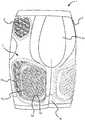
- FIG. 1is a perspective view of a protective garment having pads in accordance with one embodiment of the invention
- FIG. 2is a front view of the protective garment having pads shown in FIG. 1 in accordance with one embodiment of the invention
- FIG. 3is a back view of the protective garment having pads shown in FIG. 1 in accordance with one embodiment of the invention
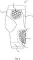
- FIG. 4is a left side view the protective garment having pads shown in FIG. 1 in accordance with one embodiment of the invention
- FIG. 5is a right side view of the protective garment having pads shown in FIG. 1 in accordance with one embodiment of the invention
- FIG. 6is a perspective view of a thigh pad in accordance with one embodiment of the invention.
- FIG. 7is a front view of the thigh pad shown in FIG. 6 in accordance with one embodiment of the invention.
- FIG. 8is a back view of the thigh pad shown in FIG. 6 in accordance with one embodiment of the invention.
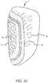
- FIG. 9is a left side view of the thigh pad shown in FIG. 6 in accordance with one embodiment of the invention.
- FIG. 10is a right side view of the thigh pad shown in FIG. 6 in accordance with one embodiment of the invention.
- FIG. 11is a top view of the thigh pad shown in FIG. 6 in accordance with one embodiment of the invention.
- FIG. 12is a bottom view of the thigh pad shown in FIG. 6 in accordance with one embodiment of the invention.
- FIG. 13illustrates pattern for protective garment in accordance with one embodiment of the invention
- FIG. 14is a thigh pad foam, including sectional views A-A′ and B-B′ in accordance with one embodiment of the invention.
- FIG. 15is a thigh pad foam, before and after die cut in accordance with one embodiment of the invention.
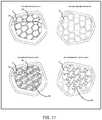
- FIG. 16is a hip pad, including sectional views A-A′ and B-B′ in accordance with one embodiment of the invention.
- FIG. 17is a hip pad, before and after die cut in accordance with one embodiment of the invention.
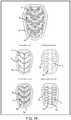
- FIG. 18is a tailbone pad, before and after die cut in accordance with one embodiment of the invention.
- FIG. 19is a thigh pad plate, including sectional view in accordance with one embodiment of the invention.
- FIG. 20is an assembly drawing of thigh pad to protective garment in accordance with one embodiment of the invention.
- one embodiment of this inventionincludes a protective garment (e.g., girdle) 1 having a body portion 1 a and a pair of left and right leg portions 1 b .
- the body portion 1 aincludes a flexible waist band adapted to surround a person's (athlete) abdomen.
- the leg portions 1 bextend above the person's knees and surround the person's thighs. However, the leg portions may also be designed to extend past the knees.
- the garment 1is made from elastic, washable and durable fabric. An example of such fabric is Lyrcra®, Spandex, and/or mesh.
- a plurality of padsare provided at locations of the garment 1 to absorb impact forces, such as from direct or indirect contact with opposing player(s), object(s), or ground surface. The locations of the pads are selected to protect the person's thighs, hips, and tailbone.
- the body portion 1 aincludes left and right hip pads 3 and a tailbone pad 5 .
- the leg portions 1 bincludes left and right thigh pads 7 .
- the thigh pad 7comprises a foam part 7 a and a thigh pad plate 7 b .
- the thigh pad foam part 7 a , hip pads 3 , and tailbone pad 5may be formed from a known foam type, including EVA, LDPE, HDPE, PU, VN, or visco-elastic foam. These components may be formed by heat compressed foam, molded, or injection foam.
- the foam thicknessmay be 5-20 mm, preferably 8-12 mm, most preferably 10 mm.
- the thigh pad plate 7 bmay be formed from a known hard plastic material, such as ABS, PP, HDPE, PC, or a composite (glass or carbon based), or any of blend of these resins, or any of these resins mixed with 0-15% glass or carbon reinforcement.
- One objective of the novel design for the various pad features included in the protective garment described hereinis to allow a user's body heat to efficiently and effectively exit the user's body surface even in locations of the user's body that are covered, padded, and protected.
- the pad designallows for moisture management properties and tactical impact energy dispersion.
- FIG. 13illustrates an embodiment of a pattern used to form the protective garment 1 .
- the patternincludes a plurality of cut lines and fold lines designed to form the overall shape of the protective garment and to accommodate the pads attached (stitched) to an outside surface of the protective garment 1 .
- the protective garment 1includes several panel portions separated by cut lines. The panel portions may be formed of mesh or lycra material, depending on the desired function of the panel portion.
- FIG. 14illustrates a foam part 7 a of left thigh pad 7 , without the pad plate 7 b .
- the foam part 7 ais formed with a plurality of channels 7 c , pad plate accommodating portion 7 b ′, and a first plurality of cutout portions 7 d .
- the thickness of foam part 7 amay be 5-20 mm, preferably 8-12 mm, most preferably 10 mm.
- the foam plate accommodating portion 7 b ′is a recessed portion having a depth of 3 mm and thickness of 7 mm; however, it is known to use a dimension suitable to accommodate a desired pad plate 7 b thereon.
- Each of the channels 7 cis preferably 5 mm deep and formed such that at least 2 mm of material remains at an upper surface thereof.
- the channelis formed 5 mm deep and there is 5 mm of material remaining at an upper surface thereof.
- the plurality of cutout portions 7 dare formed as vertical through-holes extending from the upper surface through a lower surface of the foam part 7 a .
- the plurality of cutout portions 7 dare formed on the entire foam part 7 a , including the pad plate accommodating portion 7 b ′.
- Each of the plurality of cutout portions 7 dmay be configured of the same shape or different shapes (e.g., aesthetics).
- the cutout portionsare formed in rows of mostly triangular shaped cutouts having rounded edges wherein the shapes of the cutout portions in adjacent rows are formed generally as mirror-images from one another.
- cutoutsit is important to arrange the cutouts in a manner that protects the user (e.g., tactical impact energy dispersion), allows the user's skin to effectively and efficiently breathe and release heat, and reduces the weight of the pads and covering. This can be accomplished by designing a pad with the most amount of cutouts in the padding and covering without compromising the protection to the player (e.g., structural integrity of the pad).
- FIG. 15illustrates a top and bottom view of the left thigh pad foam part 7 a , before and after a die cut process used to form the plurality of cutout portions 7 d .
- the pad plate accommodating portion 7 b ′ in this embodimentis a 3 mm recess designed to fit the pad plate 7 b .
- the thigh pad 7includes a stitching tab portion 7 e formed along the contour of the thigh pad 7 .
- the stitching tab portion 7 eis preferably formed free of cutout portions 7 d in order to allow for continuous stitching of the thigh pad 7 to the protective garment 1 along the entire contour of the thigh pad 7 .
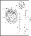
- FIG. 19illustrates a thigh pad plate 7 b .
- the thigh pad plate 7 bis arranged (e.g., stitched) on a top of pad plate accommodating portion 7 b ′.
- the thigh pad plate 7 bmay be made with a flexible plastic material that has a certain amount of flexibility and that is stitchable for stitching the thigh pad plate 7 b to the foam part 7 a .
- the thigh pad plate 7 bmay alternatively include holes formed on a contour thereof to allow for stitching the pad plate 7 b to the foam part 7 a .
- other known attaching meanscan be used to attach the pad plate 7 b to the foam part 7 a .
- the pad plate 7 bmay be inserted into pockets on the foam part 7 a or protective garment 1 .
- the thigh pad plate 7 bmay be formed from a known hard plastic material, such as ABS, PP, HDPE, PC, or a composite (glass or carbon based), any of blend of these resins, or any of these resins mixed with 0-15% glass or carbon reinforcement.
- a second plurality of spaced-apart cutout portions 7 d ′is formed in a central section 7 f of the thigh pad plate 7 b , which may be surrounded by an outer edge 7 g of the thigh pad plate. As shown in FIG. 19 , the outer edge 7 g does not include the spaced-apart cutout portions 7 d ′.
- the pad plate 7 bis located on a surface of the thigh pad 7 so that each of the cutout portions 7 d ′ are arranged generally in line with the corresponding underlying cutout portions 7 d of the foam part 7 a , as shown in FIGS. 1, 2, and 6-10 .
- the cutout portions 7 d ′ of the thigh pad plate and the cutout portions of the foam part 7 amay be formed in a grid pattern.
- an exemplary cutout portion 7 d′amay be spaced apart from the outer edge 7 g of the thigh pad plate 7 b , such that the cutout portion 7 d′a is situated entirely within the central section 7 f of the thigh pad plate.
- each of the cutout portion 7 d ′is formed to taper inward.
- Each cutout portion 7 d ′is spaced apart approximately 6 mm from each adjacent cutout portion 7 d ′ and is approximately 6 mm in depth.
- a dimension suitable to mate with the corresponding foam part 7 a and to provide adequate structural integrity for the desired impact absorption propertiescan be used.
- the cutout portions 7 d ′ of pad plate 7 bprovide a large amount of ventilation while still providing strength for impact protection. As shown in FIG. 7 , the cutout portions 7 d ′ of the pad plate 7 b provide a certain opening percentage relative to the total surface in a zone defined by the outer perimeter of the pad plate 7 b cutout portions 7 d ′.
- FIG. 8shows the inner surface of the foam part. In FIG. 8 , the inner openings of the cutout portions of the pad plate 7 b correspond with the cutout portions of the foam part 7 a excluding the cutout portions grouped together along the right edge of the foam part.
- the opening percentage calculated based on the inner openings of cutout portions 7 d ′ relative to the total surface in the zone defined by the outer perimeter of the cutout portions 7 d ′ of pad plate 7 b on the inner surface (leg side)is preferably 10% or more preferably 15% or more, more preferably 20% or more.
- the opening percentage of the inner opening of cutout portions 7 d ′is preferably 50% or less, more preferably 40% or less, more preferably 30% or less, more preferably 25% or less.
- FIG. 7shows an opening percentage of 22% for the inner openings of cutout portions 7 d ′ relative to the total surface in the zone defined by the outer perimeter of the cutout portions 7 d ′ of pad plate 7 b.
- the channels in the thigh pad plate 7 bprovide ventilation and also disperse impact energy to the foam part 7 a more efficiently than a solid hard plate.
- Moisture-wicking technology in the fabric of the protective garment 1is designed to remove sweat and to accelerate evaporation and cooling.
- Mesh panels, e.g., poly spandex,enhance ventilation to keep the user's core body temperature generally consistent and cool.
- Compression fabric portions of the protective garmentare provided to contour to the user's body for optimal fit and improved range of motion.
- Flat seam design of the protective garment 1is designed to diminish irritation during movement.
- the protective garment 1 and padsmay include anti-microbial treatment to reduce odor causing bacteria.
- FIG. 16illustrates a left side hip pad 3 .
- the hip pad 3is formed with a plurality of channels 3 c , a plurality of cutout portions 3 d , and a contour stitching tab 3 e .
- the hip pad 3may include a horizontal channel 3 b , preferably 5 mm thick extending horizontally from one end portion of the hip pad 3 to the opposite end portion of the hip pad 3 .
- the thickness of hip pad 3may be 6-20 mm, preferably 8-12 mm, most preferably 10 mm.
- Each of the channels 3 cis preferably 5 mm deep and formed such that at least 2 mm of material remains at an upper surface thereof for structural integrity.
- the vertical portion above the channelis 5 mm thick.
- the plurality of cutout portions 3 dare formed as vertical through-holes extending from the upper surface through a lower surface of the hip pad 3 .
- the contour stitching tab portion 3 eis formed along the contour of the hip pad 3 .
- the stitching tab portion 3 eis preferably formed free of cutout portions 3 d in order to allow for continuous stitching of the hip pad 3 to the protective garment 1 along the entire contour of the thigh pad 3 .
- Each of the plurality of cutout portions 3 dmay be configured of the same shape or different shapes.
- the cutout portionsare formed in rows of mostly triangular shaped cutouts having rounded edges wherein the shapes of the cutout portions in adjacent rows are formed generally as mirror-images from one another.
- FIG. 17illustrates a top and bottom view of the left hip pad 3 , before and after a die cut process used to form the plurality of cutout portions 3 d.
- FIG. 18illustrates a tailbone pad 5 .
- the tailbone pad 5is formed with a plurality of channels 5 c , a plurality of cutout portions 5 d , and a contour stitching tab 5 e .
- the thickness of tailbone pad 5may be 6-20 mm, preferably 8-12 mm, most preferably 10 mm.
- Each of the channels 5 cis preferably 5 mm deep and formed such that at least 2 mm of material remains at an upper surface thereof for structural integrity. For example, in a 10 mm portion tailbone pad 5 including a channel formed 5 mm deep, the vertical portion above the channel is 5 mm thick.
- the plurality of cutout portions 5 dare formed as vertical through-holes extending from the upper surface through a lower surface of the tailbone pad 5 .
- the contour stitching tab portion 5 eis formed along the contour of the tailbone pad 5 .
- the stitching tab portion 5 eis preferably formed free of cutout portions 5 d in order to allow for continuous stitching of the tailbone pad 5 to the protective garment 1 along the entire contour of the tailbone pad 5 .
- Each of the plurality of cutout portions 5 dmay be configured of the same shape or different shapes. In this embodiment, for example, the cutout portions are formed in rows of mostly triangular shaped cutouts having rounded edges wherein the shapes of the cutout portions in adjacent rows are formed generally as mirror-images from one another.
- FIG. 20is a drawing illustrating an assembly of the thigh pad plate 7 b to the thigh pad foam 7 a , and the thigh pad 7 to the protective garment 1 .
- the thigh pad plate 7 bis attached to the pad plate accommodating portion 7 b ′ of the foam part 7 a so that each of the cutout portions 7 d ′ are arranged generally in line with the corresponding underlying cutout portions 7 d of the foam part 7 a , as shown in FIGS. 1, 2, and 6-10 .
- FIG. 1is a drawing illustrating an assembly of the thigh pad plate 7 b to the thigh pad foam 7 a , and the thigh pad 7 to the protective garment 1 .
- the thigh pad plate 7 bis attached to the pad plate accommodating portion 7 b ′ of the foam part 7 a so that each of the cutout portions 7 d ′ are arranged generally in line with the corresponding underlying cutout portions 7 d of the foam part 7 a , as shown in
- the pad plate 7 bmay be attached to the foam part 7 a by stitching the outer edge 7 q of the pad plate 7 b to pad plate accommodating portion 7 b ′ of the foam part 7 a via the holes formed in the stitching tab portion 7 e .
- the thigh pad plate 7 bmay be concave such that a portion of the central section 7 f of the thigh pad plate (e.g., plate portion 7 h in FIGS. 19 and 20 ) is spaced apart from the pad plate accommodating portion 7 b ′.
- the plate portion 7 hmay include the cutout portion 7 d ′a.
- the thigh pad 7integrally comprising the foam part 7 a and plate portion 7 b , is then attached to the protective garment.
- the thigh pad 7may be attached to the protective garment 1 by placing the thigh pad 7 on an inner side of a desired location on the protective garment 1 , preferably floating mesh layer, and performing a flatlock (flatseam) contour seam.
- a flatlockflatseam
- other known methods, such as cover stitching and overlockingmay be performed.
- the hip pad 3 and tailbone pad 5may also be attached to the protective garment 1 by placing the respective pad on an inner side of a desired location on the protective garment 1 , preferably floating mesh layer, and performing a flatlock (flatseam) contour seam.
Landscapes
- Health & Medical Sciences (AREA)
- Engineering & Computer Science (AREA)
- Textile Engineering (AREA)
- General Health & Medical Sciences (AREA)
- Physical Education & Sports Medicine (AREA)
- Orthopedic Medicine & Surgery (AREA)
- Professional, Industrial, Or Sporting Protective Garments (AREA)
- Corsets Or Brassieres (AREA)
- Details Of Garments (AREA)
Abstract
Description
Claims (20)
Priority Applications (2)
| Application Number | Priority Date | Filing Date | Title |
|---|---|---|---|
| US15/840,605US10765928B2 (en) | 2016-12-16 | 2017-12-13 | Protective pad for protection from impact and a protective garment using the same |
| US17/014,046US12311249B2 (en) | 2016-12-16 | 2020-09-08 | Protective pad for protection from impact and a protective garment using the same |
Applications Claiming Priority (2)
| Application Number | Priority Date | Filing Date | Title |
|---|---|---|---|
| US201662498133P | 2016-12-16 | 2016-12-16 | |
| US15/840,605US10765928B2 (en) | 2016-12-16 | 2017-12-13 | Protective pad for protection from impact and a protective garment using the same |
Related Child Applications (1)
| Application Number | Title | Priority Date | Filing Date |
|---|---|---|---|
| US17/014,046ContinuationUS12311249B2 (en) | 2016-12-16 | 2020-09-08 | Protective pad for protection from impact and a protective garment using the same |
Publications (2)
| Publication Number | Publication Date |
|---|---|
| US20180169505A1 US20180169505A1 (en) | 2018-06-21 |
| US10765928B2true US10765928B2 (en) | 2020-09-08 |
Family
ID=62556542
Family Applications (2)
| Application Number | Title | Priority Date | Filing Date |
|---|---|---|---|
| US15/840,605Active - Reinstated2038-02-14US10765928B2 (en) | 2016-12-16 | 2017-12-13 | Protective pad for protection from impact and a protective garment using the same |
| US17/014,046Active2038-07-22US12311249B2 (en) | 2016-12-16 | 2020-09-08 | Protective pad for protection from impact and a protective garment using the same |
Family Applications After (1)
| Application Number | Title | Priority Date | Filing Date |
|---|---|---|---|
| US17/014,046Active2038-07-22US12311249B2 (en) | 2016-12-16 | 2020-09-08 | Protective pad for protection from impact and a protective garment using the same |
Country Status (1)
| Country | Link |
|---|---|
| US (2) | US10765928B2 (en) |
Cited By (1)
| Publication number | Priority date | Publication date | Assignee | Title |
|---|---|---|---|---|
| USD1020108S1 (en)* | 2021-04-14 | 2024-03-26 | 100% Speedlab, Llc | Protective pad |
Families Citing this family (9)
| Publication number | Priority date | Publication date | Assignee | Title |
|---|---|---|---|---|
| US20180192718A1 (en)* | 2017-01-06 | 2018-07-12 | Sweet And Vicious, Llc | Buttock enhancing pad |
| WO2020157372A1 (en)* | 2019-02-01 | 2020-08-06 | Tackla Licensing Corporation Oy | A protective structure for protective garments and equipment |
| USD1072423S1 (en)* | 2023-04-21 | 2025-04-29 | Nike, Inc. | Shorts |
| USD1073260S1 (en) | 2023-04-21 | 2025-05-06 | Nike, Inc. | Shirt |
| USD1077421S1 (en) | 2023-04-21 | 2025-06-03 | Nike, Inc. | Shirt |
| USD1069326S1 (en) | 2023-04-21 | 2025-04-08 | Nike, Inc. | Shirt |
| USD1080143S1 (en)* | 2023-07-05 | 2025-06-24 | Xiaoqin Lin | Sports suit |
| KR102809781B1 (en)* | 2024-08-20 | 2025-05-21 | 주식회사 제이스버디 | Leggings including functional impact absorbing pad |
| KR102809782B1 (en)* | 2024-08-20 | 2025-05-21 | 주식회사 제이스버디 | Leggings including function for sweat suit |
Citations (33)
| Publication number | Priority date | Publication date | Assignee | Title |
|---|---|---|---|---|
| US759833A (en) | 1904-03-10 | 1904-05-10 | Stall & Dean Mfg Co | Foot-ball trousers. |
| US2266886A (en) | 1940-08-05 | 1941-12-23 | Goodrich Co B F | Protective body pad |
| US4035844A (en) | 1971-04-27 | 1977-07-19 | Atack James W | Novel trouser-like article of clothing |
| US4486901A (en) | 1982-03-12 | 1984-12-11 | Houston Protective Equipment, Inc. | Multi-layered, open-celled foam shock absorbing structure for athletic equipment |
| US4513449A (en) | 1983-03-25 | 1985-04-30 | Donzis Byron A | Shock absorbing athletic equipment |
| US5168576A (en)* | 1990-10-03 | 1992-12-08 | Krent Edward D | Body protective device |
| US5322730A (en)* | 1993-01-15 | 1994-06-21 | Ou Jer Wen | Elastic permeable material and method of making same |
| US5557804A (en)* | 1993-11-16 | 1996-09-24 | Ovortrup Aps | Protective appliance |
| US5680657A (en)* | 1993-10-19 | 1997-10-28 | L-Fashion Group Oy | Protective pad |
| US5701611A (en) | 1995-12-05 | 1997-12-30 | Ed Tobergte Associates, Inc. | Protective pad construction |
| US5781935A (en) | 1996-10-09 | 1998-07-21 | Bassett; Aldean B. | Padded body protection pads |
| US5920915A (en) | 1998-09-22 | 1999-07-13 | Brock Usa, Llc | Protective padding for sports gear |
| US6032300A (en) | 1998-09-22 | 2000-03-07 | Brock Usa, Llc | Protective padding for sports gear |
| US6079056A (en)* | 1999-02-09 | 2000-06-27 | Fogelberg; Val O. | Air cushioning device for sports use |
| US6093468A (en)* | 1997-03-14 | 2000-07-25 | The Procter & Gamble Company | Flexible lightweight protective pad with energy absorbing inserts |
| US6279160B1 (en)* | 1999-03-15 | 2001-08-28 | Asics Corp | Knee and elbow protector |
| US6336220B1 (en) | 1997-05-29 | 2002-01-08 | Trauma-Lite Limited | Protective element |
| US6845522B2 (en) | 2000-12-12 | 2005-01-25 | Bauer Nike Hockey Inc. | Shoulder pads with integral arm protectors |
| US6880269B2 (en) | 2001-10-16 | 2005-04-19 | Sting Free Company | Athletic clothing with sting reduction padding |
| US7168104B2 (en) | 2003-10-23 | 2007-01-30 | Ed Tobergte Associates Company | Football shoulder pads |
| US7389547B1 (en) | 2004-09-28 | 2008-06-24 | Wiens Joel J | Athletic garment with adjustable leg shields |
| USD582608S1 (en)* | 2006-08-21 | 2008-12-09 | Design Blue Limited | Protective pad for sportswear |
| US20090276933A1 (en)* | 2005-02-15 | 2009-11-12 | Dodd Mark D | Protective articles having a plurality of core members |
| US20100319097A1 (en)* | 2009-06-23 | 2010-12-23 | Nike, Inc. | Apparel Incorporating A Protective Element |
| USD633688S1 (en) | 2009-12-18 | 2011-03-08 | Nike, Inc. | Compression shorts |
| US8220072B2 (en)* | 2005-02-15 | 2012-07-17 | The Dodd Group, LLC | Protective shin guard |
| US20130025037A1 (en)* | 2011-07-25 | 2013-01-31 | Nike, Inc. | Articles Of Apparel Incorporating Cushioning Elements |
| US20130234376A1 (en)* | 2012-03-08 | 2013-09-12 | Nike, Inc. | Protective Pad Using A Damping Component |
| US9149084B2 (en)* | 2009-06-23 | 2015-10-06 | Nike, Inc. | Apparel incorporating a protective element and method for making |
| US9352531B2 (en)* | 2010-01-22 | 2016-05-31 | Under Armour, Inc. | Padding arrangement and method of making the same |
| US9615611B2 (en)* | 2011-08-11 | 2017-04-11 | G-Form, LLC | Breathable impact absorbing cushioning and constructions |
| US9962902B2 (en)* | 2013-04-08 | 2018-05-08 | Technogel Italia S.R.L. | Padding element for seats and method of manufacturing the same |
| US10021922B2 (en)* | 2013-07-01 | 2018-07-17 | Nike, Inc. | Modular impact protection system for athletic wear |
Family Cites Families (2)
| Publication number | Priority date | Publication date | Assignee | Title |
|---|---|---|---|---|
| US8272073B2 (en)* | 2005-02-17 | 2012-09-25 | Stromgren Athletics, Inc. | Athletic protective padding |
| US9908027B2 (en)* | 2014-04-22 | 2018-03-06 | Nike, Inc. | Article of apparel with dynamic padding system |
- 2017
- 2017-12-13USUS15/840,605patent/US10765928B2/enactiveActive - Reinstated
- 2020
- 2020-09-08USUS17/014,046patent/US12311249B2/enactiveActive
Patent Citations (33)
| Publication number | Priority date | Publication date | Assignee | Title |
|---|---|---|---|---|
| US759833A (en) | 1904-03-10 | 1904-05-10 | Stall & Dean Mfg Co | Foot-ball trousers. |
| US2266886A (en) | 1940-08-05 | 1941-12-23 | Goodrich Co B F | Protective body pad |
| US4035844A (en) | 1971-04-27 | 1977-07-19 | Atack James W | Novel trouser-like article of clothing |
| US4486901A (en) | 1982-03-12 | 1984-12-11 | Houston Protective Equipment, Inc. | Multi-layered, open-celled foam shock absorbing structure for athletic equipment |
| US4513449A (en) | 1983-03-25 | 1985-04-30 | Donzis Byron A | Shock absorbing athletic equipment |
| US5168576A (en)* | 1990-10-03 | 1992-12-08 | Krent Edward D | Body protective device |
| US5322730A (en)* | 1993-01-15 | 1994-06-21 | Ou Jer Wen | Elastic permeable material and method of making same |
| US5680657A (en)* | 1993-10-19 | 1997-10-28 | L-Fashion Group Oy | Protective pad |
| US5557804A (en)* | 1993-11-16 | 1996-09-24 | Ovortrup Aps | Protective appliance |
| US5701611A (en) | 1995-12-05 | 1997-12-30 | Ed Tobergte Associates, Inc. | Protective pad construction |
| US5781935A (en) | 1996-10-09 | 1998-07-21 | Bassett; Aldean B. | Padded body protection pads |
| US6093468A (en)* | 1997-03-14 | 2000-07-25 | The Procter & Gamble Company | Flexible lightweight protective pad with energy absorbing inserts |
| US6336220B1 (en) | 1997-05-29 | 2002-01-08 | Trauma-Lite Limited | Protective element |
| US6032300A (en) | 1998-09-22 | 2000-03-07 | Brock Usa, Llc | Protective padding for sports gear |
| US5920915A (en) | 1998-09-22 | 1999-07-13 | Brock Usa, Llc | Protective padding for sports gear |
| US6079056A (en)* | 1999-02-09 | 2000-06-27 | Fogelberg; Val O. | Air cushioning device for sports use |
| US6279160B1 (en)* | 1999-03-15 | 2001-08-28 | Asics Corp | Knee and elbow protector |
| US6845522B2 (en) | 2000-12-12 | 2005-01-25 | Bauer Nike Hockey Inc. | Shoulder pads with integral arm protectors |
| US6880269B2 (en) | 2001-10-16 | 2005-04-19 | Sting Free Company | Athletic clothing with sting reduction padding |
| US7168104B2 (en) | 2003-10-23 | 2007-01-30 | Ed Tobergte Associates Company | Football shoulder pads |
| US7389547B1 (en) | 2004-09-28 | 2008-06-24 | Wiens Joel J | Athletic garment with adjustable leg shields |
| US8220072B2 (en)* | 2005-02-15 | 2012-07-17 | The Dodd Group, LLC | Protective shin guard |
| US20090276933A1 (en)* | 2005-02-15 | 2009-11-12 | Dodd Mark D | Protective articles having a plurality of core members |
| USD582608S1 (en)* | 2006-08-21 | 2008-12-09 | Design Blue Limited | Protective pad for sportswear |
| US20100319097A1 (en)* | 2009-06-23 | 2010-12-23 | Nike, Inc. | Apparel Incorporating A Protective Element |
| US9149084B2 (en)* | 2009-06-23 | 2015-10-06 | Nike, Inc. | Apparel incorporating a protective element and method for making |
| USD633688S1 (en) | 2009-12-18 | 2011-03-08 | Nike, Inc. | Compression shorts |
| US9352531B2 (en)* | 2010-01-22 | 2016-05-31 | Under Armour, Inc. | Padding arrangement and method of making the same |
| US20130025037A1 (en)* | 2011-07-25 | 2013-01-31 | Nike, Inc. | Articles Of Apparel Incorporating Cushioning Elements |
| US9615611B2 (en)* | 2011-08-11 | 2017-04-11 | G-Form, LLC | Breathable impact absorbing cushioning and constructions |
| US20130234376A1 (en)* | 2012-03-08 | 2013-09-12 | Nike, Inc. | Protective Pad Using A Damping Component |
| US9962902B2 (en)* | 2013-04-08 | 2018-05-08 | Technogel Italia S.R.L. | Padding element for seats and method of manufacturing the same |
| US10021922B2 (en)* | 2013-07-01 | 2018-07-17 | Nike, Inc. | Modular impact protection system for athletic wear |
Non-Patent Citations (3)
| Title |
|---|
| Acerbis Product, Nov. 2017. |
| Bike Athletic Company, Catalog, Oct. 2002, pp. 2-8. |
| LEATT Product, Nov. 2017. |
Cited By (1)
| Publication number | Priority date | Publication date | Assignee | Title |
|---|---|---|---|---|
| USD1020108S1 (en)* | 2021-04-14 | 2024-03-26 | 100% Speedlab, Llc | Protective pad |
Also Published As
| Publication number | Publication date |
|---|---|
| US20200398143A1 (en) | 2020-12-24 |
| US12311249B2 (en) | 2025-05-27 |
| US20180169505A1 (en) | 2018-06-21 |
Similar Documents
| Publication | Publication Date | Title |
|---|---|---|
| US12311249B2 (en) | Protective pad for protection from impact and a protective garment using the same | |
| US8272073B2 (en) | Athletic protective padding | |
| US7389547B1 (en) | Athletic garment with adjustable leg shields | |
| US8438669B2 (en) | Apparel incorporating a protective element | |
| US7731564B2 (en) | Undergarment with memory foam insert | |
| US10194707B2 (en) | Apparel incorporating a protective element | |
| US8302212B1 (en) | Athletic garment | |
| US20060179545A1 (en) | Athletic protective padding | |
| US8095996B2 (en) | Apparel incorporating a protective element | |
| US4325148A (en) | Uniforms for ice hockey players | |
| US6446273B1 (en) | Protective body vest | |
| US20110010829A1 (en) | Combined neck and upper body protective garment | |
| US20140259260A1 (en) | Protective Ankle And Calf Sleeve | |
| US20150101110A1 (en) | Protective padding assembly for a sports apparel article | |
| US20050075046A1 (en) | Protective undergarment for a football player | |
| US10736363B2 (en) | High-performance sports bra | |
| US20150113717A1 (en) | Protective Athletic Garment | |
| US7082621B1 (en) | Thigh pad protectors | |
| US12075862B2 (en) | Fitness clothing with protective padding | |
| US20200170317A1 (en) | Protective garment for female adult and youth sports participants | |
| US12303767B2 (en) | Hockey pants with floating abdominal protection | |
| CA2670914A1 (en) | Combined neck and upper body protective garment | |
| WO2017118837A1 (en) | Lower leg garment |
Legal Events
| Date | Code | Title | Description |
|---|---|---|---|
| AS | Assignment | Owner name:BSN SPORTS, LLC, TEXAS Free format text:ASSIGNMENT OF ASSIGNORS INTEREST;ASSIGNORS:PIOMBINO, DON;JOURDE, BASTIEN;SIGNING DATES FROM 20171211 TO 20171212;REEL/FRAME:044862/0193 | |
| FEPP | Fee payment procedure | Free format text:ENTITY STATUS SET TO UNDISCOUNTED (ORIGINAL EVENT CODE: BIG.); ENTITY STATUS OF PATENT OWNER: LARGE ENTITY | |
| STPP | Information on status: patent application and granting procedure in general | Free format text:DOCKETED NEW CASE - READY FOR EXAMINATION | |
| STPP | Information on status: patent application and granting procedure in general | Free format text:NON FINAL ACTION MAILED | |
| STPP | Information on status: patent application and granting procedure in general | Free format text:RESPONSE TO NON-FINAL OFFICE ACTION ENTERED AND FORWARDED TO EXAMINER | |
| STPP | Information on status: patent application and granting procedure in general | Free format text:FINAL REJECTION MAILED | |
| STPP | Information on status: patent application and granting procedure in general | Free format text:DOCKETED NEW CASE - READY FOR EXAMINATION | |
| ZAAA | Notice of allowance and fees due | Free format text:ORIGINAL CODE: NOA | |
| ZAAB | Notice of allowance mailed | Free format text:ORIGINAL CODE: MN/=. | |
| AS | Assignment | Owner name:ANKURA TRUST COMPANY, LLC, CONNECTICUT Free format text:SECURITY INTEREST;ASSIGNORS:BSN SPORTS, LLC;VARSITY SPIRIT, LLC;HERFF JONES, LLC;REEL/FRAME:053253/0288 Effective date:20200622 | |
| STCF | Information on status: patent grant | Free format text:PATENTED CASE | |
| AS | Assignment | Owner name:HERFF JONES, LLC, TENNESSEE Free format text:RELEASE OF PATENT INTEREST (REEL 053253 / FRAME 0288);ASSIGNOR:ANKURA TRUST COMPANY, LLC;REEL/FRAME:065448/0977 Effective date:20231102 Owner name:VARSITY SPIRIT LLC, TENNESSEE Free format text:RELEASE OF PATENT INTEREST (REEL 053253 / FRAME 0288);ASSIGNOR:ANKURA TRUST COMPANY, LLC;REEL/FRAME:065448/0977 Effective date:20231102 Owner name:BSN SPORTS, LLC, TENNESSEE Free format text:RELEASE OF PATENT INTEREST (REEL 053253 / FRAME 0288);ASSIGNOR:ANKURA TRUST COMPANY, LLC;REEL/FRAME:065448/0977 Effective date:20231102 Owner name:ANKURA TRUST COMPANY, LLC, AS COLLATERAL AGENT, CONNECTICUT Free format text:SECURITY AGREEMENT;ASSIGNOR:BSN SPORTS, LLC;REEL/FRAME:065449/0004 Effective date:20231102 | |
| FEPP | Fee payment procedure | Free format text:MAINTENANCE FEE REMINDER MAILED (ORIGINAL EVENT CODE: REM.); ENTITY STATUS OF PATENT OWNER: LARGE ENTITY | |
| AS | Assignment | Owner name:BSN SPORTS, LLC, TEXAS Free format text:RELEASE OF SECURITY INTEREST IN PATENTS;ASSIGNOR:ANKURA TRUST COMPANY, LLC;REEL/FRAME:069127/0471 Effective date:20240826 | |
| LAPS | Lapse for failure to pay maintenance fees | Free format text:PATENT EXPIRED FOR FAILURE TO PAY MAINTENANCE FEES (ORIGINAL EVENT CODE: EXP.); ENTITY STATUS OF PATENT OWNER: LARGE ENTITY | |
| STCH | Information on status: patent discontinuation | Free format text:PATENT EXPIRED DUE TO NONPAYMENT OF MAINTENANCE FEES UNDER 37 CFR 1.362 | |
| FP | Lapsed due to failure to pay maintenance fee | Effective date:20240908 | |
| AS | Assignment | Owner name:BANK OF AMERICA, N.A., NORTH CAROLINA Free format text:SECURITY INTEREST;ASSIGNORS:VARSITY BRANDS, INC.;HERCULES VB HOLDINGS, LLC;HERCULES ACHIEVEMENT HOLDINGS, LLC;AND OTHERS;REEL/FRAME:069332/0876 Effective date:20240826 Owner name:BANK OF AMERICA, N.A., NORTH CAROLINA Free format text:SECURITY INTEREST;ASSIGNORS:VARSITY BRANDS, INC.;HERCULES VB HOLDINGS, LLC;HERCULES ACHIEVEMENT HOLDINGS, LLC;AND OTHERS;REEL/FRAME:069327/0804 Effective date:20240826 | |
| PRDP | Patent reinstated due to the acceptance of a late maintenance fee | Effective date:20250521 | |
| FEPP | Fee payment procedure | Free format text:PETITION RELATED TO MAINTENANCE FEES FILED (ORIGINAL EVENT CODE: PMFP); ENTITY STATUS OF PATENT OWNER: LARGE ENTITY Free format text:PETITION RELATED TO MAINTENANCE FEES GRANTED (ORIGINAL EVENT CODE: PMFG); ENTITY STATUS OF PATENT OWNER: LARGE ENTITY Free format text:SURCHARGE, PETITION TO ACCEPT PYMT AFTER EXP, UNINTENTIONAL (ORIGINAL EVENT CODE: M1558); ENTITY STATUS OF PATENT OWNER: LARGE ENTITY | |
| MAFP | Maintenance fee payment | Free format text:PAYMENT OF MAINTENANCE FEE, 4TH YEAR, LARGE ENTITY (ORIGINAL EVENT CODE: M1551); ENTITY STATUS OF PATENT OWNER: LARGE ENTITY Year of fee payment:4 | |
| STCF | Information on status: patent grant | Free format text:PATENTED CASE |