US10765516B2 - Device and method for improving the function of a heart valve - Google Patents
Device and method for improving the function of a heart valveDownload PDFInfo
- Publication number
- US10765516B2 US10765516B2US16/246,374US201916246374AUS10765516B2US 10765516 B2US10765516 B2US 10765516B2US 201916246374 AUS201916246374 AUS 201916246374AUS 10765516 B2US10765516 B2US 10765516B2
- Authority
- US
- United States
- Prior art keywords
- shape
- valve
- contact
- heart
- commissures
- Prior art date
- Legal status (The legal status is an assumption and is not a legal conclusion. Google has not performed a legal analysis and makes no representation as to the accuracy of the status listed.)
- Expired - Fee Related
Links
- 210000003709heart valveAnatomy0.000titleclaimsabstractdescription75
- 238000000034methodMethods0.000titledescription14
- 230000008859changeEffects0.000claimsabstractdescription17
- 230000009471actionEffects0.000claimsabstractdescription14
- 238000003780insertionMethods0.000claimsabstractdescription7
- 230000037431insertionEffects0.000claimsabstractdescription7
- 210000004115mitral valveAnatomy0.000claimsdescription49
- 230000006870functionEffects0.000claimsdescription14
- 238000012546transferMethods0.000claimsdescription13
- 230000000452restraining effectEffects0.000claimsdescription5
- 230000007704transitionEffects0.000claimsdescription4
- 239000012781shape memory materialSubstances0.000claimsdescription3
- 230000002861ventricularEffects0.000claimsdescription3
- 229910001000nickel titaniumInorganic materials0.000claimsdescription2
- HLXZNVUGXRDIFK-UHFFFAOYSA-Nnickel titaniumChemical compound[Ti].[Ti].[Ti].[Ti].[Ti].[Ti].[Ti].[Ti].[Ti].[Ti].[Ti].[Ni].[Ni].[Ni].[Ni].[Ni].[Ni].[Ni].[Ni].[Ni].[Ni].[Ni].[Ni].[Ni].[Ni]HLXZNVUGXRDIFK-UHFFFAOYSA-N0.000claimsdescription2
- 229910001285shape-memory alloyInorganic materials0.000claimsdescription2
- 229920000431shape-memory polymerPolymers0.000claimsdescription2
- 230000000149penetrating effectEffects0.000claims2
- 210000001519tissueAnatomy0.000description58
- 210000005240left ventricleAnatomy0.000description9
- 230000017531blood circulationEffects0.000description7
- 239000008280bloodSubstances0.000description4
- 210000004369bloodAnatomy0.000description4
- 210000005246left atriumAnatomy0.000description4
- 239000000463materialSubstances0.000description4
- 230000008439repair processEffects0.000description4
- 238000007634remodelingMethods0.000description3
- MWCLLHOVUTZFKS-UHFFFAOYSA-NMethyl cyanoacrylateChemical compoundCOC(=O)C(=C)C#NMWCLLHOVUTZFKS-UHFFFAOYSA-N0.000description2
- 208000007536ThrombosisDiseases0.000description2
- 238000004873anchoringMethods0.000description2
- 210000001765aortic valveAnatomy0.000description2
- 238000010438heat treatmentMethods0.000description2
- 229910000734martensiteInorganic materials0.000description2
- 238000001356surgical procedureMethods0.000description2
- 210000000591tricuspid valveAnatomy0.000description2
- 230000003213activating effectEffects0.000description1
- 230000002785anti-thrombosisEffects0.000description1
- 210000000709aortaAnatomy0.000description1
- 238000013459approachMethods0.000description1
- 210000001367arteryAnatomy0.000description1
- 230000001746atrial effectEffects0.000description1
- 230000008901benefitEffects0.000description1
- 230000023555blood coagulationEffects0.000description1
- 210000005242cardiac chamberAnatomy0.000description1
- 230000008602contractionEffects0.000description1
- 230000001419dependent effectEffects0.000description1
- 230000004064dysfunctionEffects0.000description1
- 210000001105femoral arteryAnatomy0.000description1
- 210000004013groinAnatomy0.000description1
- 230000004217heart functionEffects0.000description1
- 238000011065in-situ storageMethods0.000description1
- 210000004971interatrial septumAnatomy0.000description1
- 230000036244malformationEffects0.000description1
- 239000002184metalSubstances0.000description1
- 229910052751metalInorganic materials0.000description1
- 150000002739metalsChemical class0.000description1
- 210000003540papillary muscleAnatomy0.000description1
- 239000004033plasticSubstances0.000description1
- 229920003023plasticPolymers0.000description1
- 238000009877renderingMethods0.000description1
- 210000005245right atriumAnatomy0.000description1
- 238000009958sewingMethods0.000description1
- 230000002966stenotic effectEffects0.000description1
- 210000003270subclavian arteryAnatomy0.000description1
- 230000001131transforming effectEffects0.000description1
Images


Classifications
- A—HUMAN NECESSITIES
- A61—MEDICAL OR VETERINARY SCIENCE; HYGIENE
- A61F—FILTERS IMPLANTABLE INTO BLOOD VESSELS; PROSTHESES; DEVICES PROVIDING PATENCY TO, OR PREVENTING COLLAPSING OF, TUBULAR STRUCTURES OF THE BODY, e.g. STENTS; ORTHOPAEDIC, NURSING OR CONTRACEPTIVE DEVICES; FOMENTATION; TREATMENT OR PROTECTION OF EYES OR EARS; BANDAGES, DRESSINGS OR ABSORBENT PADS; FIRST-AID KITS
- A61F2/00—Filters implantable into blood vessels; Prostheses, i.e. artificial substitutes or replacements for parts of the body; Appliances for connecting them with the body; Devices providing patency to, or preventing collapsing of, tubular structures of the body, e.g. stents
- A61F2/02—Prostheses implantable into the body
- A61F2/24—Heart valves ; Vascular valves, e.g. venous valves; Heart implants, e.g. passive devices for improving the function of the native valve or the heart muscle; Transmyocardial revascularisation [TMR] devices; Valves implantable in the body
- A61F2/2442—Annuloplasty rings or inserts for correcting the valve shape; Implants for improving the function of a native heart valve
- A61F2/2445—Annuloplasty rings in direct contact with the valve annulus
- A—HUMAN NECESSITIES
- A61—MEDICAL OR VETERINARY SCIENCE; HYGIENE
- A61F—FILTERS IMPLANTABLE INTO BLOOD VESSELS; PROSTHESES; DEVICES PROVIDING PATENCY TO, OR PREVENTING COLLAPSING OF, TUBULAR STRUCTURES OF THE BODY, e.g. STENTS; ORTHOPAEDIC, NURSING OR CONTRACEPTIVE DEVICES; FOMENTATION; TREATMENT OR PROTECTION OF EYES OR EARS; BANDAGES, DRESSINGS OR ABSORBENT PADS; FIRST-AID KITS
- A61F2220/00—Fixations or connections for prostheses classified in groups A61F2/00 - A61F2/26 or A61F2/82 or A61F9/00 or A61F11/00 or subgroups thereof
- A61F2220/0008—Fixation appliances for connecting prostheses to the body
- A—HUMAN NECESSITIES
- A61—MEDICAL OR VETERINARY SCIENCE; HYGIENE
- A61F—FILTERS IMPLANTABLE INTO BLOOD VESSELS; PROSTHESES; DEVICES PROVIDING PATENCY TO, OR PREVENTING COLLAPSING OF, TUBULAR STRUCTURES OF THE BODY, e.g. STENTS; ORTHOPAEDIC, NURSING OR CONTRACEPTIVE DEVICES; FOMENTATION; TREATMENT OR PROTECTION OF EYES OR EARS; BANDAGES, DRESSINGS OR ABSORBENT PADS; FIRST-AID KITS
- A61F2250/00—Special features of prostheses classified in groups A61F2/00 - A61F2/26 or A61F2/82 or A61F9/00 or A61F11/00 or subgroups thereof
- A61F2250/0004—Special features of prostheses classified in groups A61F2/00 - A61F2/26 or A61F2/82 or A61F9/00 or A61F11/00 or subgroups thereof adjustable
- A61F2250/0007—Special features of prostheses classified in groups A61F2/00 - A61F2/26 or A61F2/82 or A61F9/00 or A61F11/00 or subgroups thereof adjustable for adjusting length
Definitions
- the present inventiongenerally relates to improving the function of a heart valve. More specifically, the invention relates to a device and a method for treating heart valves having various malformations and dysfunctions.
- mitral and tricuspid valvesfrequently need replacement or repair.
- the mitral and tricuspid valve leaflets or supporting chordaemay degenerate and weaken or the annulus may dilate leading to valve leak (insufficiency).
- the leaflets and chordsmay become calcified and thickened rendering them stenotic (obstructing forward flow).
- the valverelies on insertion of the chordae inside the ventricle. If the ventricle changes in shape, the valve support may become non-functional and the valve may leak.
- the leafletsare attached to each other at free edges of the leaflets by means of sewing or a clip. This implies that two orifices are created, one on each side of the attachment of the leaflets. These double orifices may then close properly.
- One devicecomprises a splint for improving the function of a valve of a heart.
- the splintincludes an elongate member configured to be positioned transverse a heart chamber so that each end of the elongate member extends through a wall of the heart, and first and second anchoring members configured to be positioned external the chamber and attached to the ends of the elongate member to fix the elongate member in a position across the chamber.
- the first anchoring memberincludes a first portion configured to contact a first region of the heart proximate the valve annulus to change a shape of the valve annulus by compressing the heart.
- the change of shape of the valve annulushelps restoring the heart function.
- the elongate memberwill be placed in the blood flow and therefore the patient will need lifelong anti-thrombosis treatment in order to prevent blood clots forming within the blood flow.
- a device for improving the function of a heart valvecomprised of valve tissue including an annulus, leaflets and at least a first and a second commissure between adjacent leaflets.
- the devicehas a first shape and a second shape and comprises a first contact point and a second contact point, wherein the device in the first shape exhibits a distance between the first contact point and the second contact point essentially corresponding to a distance between said first and second commissure of the heart valve and the device in the second shape exhibits an increased distance between the first and the second contact points.
- the deviceis arranged for insertion to the heart valve to establish a contact between the first contact point and valve tissue at the first commissure and to establish a contact between the second contact point and valve tissue at the second commissure.
- the deviceis transferable from said first shape to said second shape when inserted to the heart valve, and, in the second shape, the device is arranged for extending along substantially its entire length between the first contact point and the second contact point in abutment with valve tissue throughout a cycle of heart action.
- the deviceprovides a first shape which is designed to fit the heart valve such that contact may be established between the device and two commissures of the heart valve. Therefore, the device presents a distance between two contact points that essentially correspond to a distance between the two commissures of the heart valve.
- the deviceneed not be placed in contact exactly in the commissure, but may make contact with valve tissue in the proximity of the commissure. Therefore, the distance between the contact points of the device in the first shape of the device need not exactly correspond to the distance between the commissures.
- the devicemay be compressed or restrained to temporarily assume or present its first shape, whereby the device assumes its second shape when the restrain on the device is released. Alternatively, the device may be transferred between two predetermined shapes.
- the device provided for accomplishing the geometrical shape changemay be applied to the heart valve so as not to interfere with the blood flow through the heart valve.
- the devicemay be placed in abutment with heart valve tissue along substantially the entire length of the device. This implies that the device may over time grow into the valve tissue, whereby the device does not present any surface of foreign material that may cause blood clot forming.
- the devicemay not need to initially abut valve tissue over its entire length.
- major parts of the devicewould need to abut valve tissue and parts which do not abut the valve tissue should be placed in close proximity to valve tissue such as to eventually grow into the valve tissue.
- the deviceis arranged to abut valve tissue throughout a cycle of heart action. This implies that the device, if grown into valve tissue, would not impair the movement of the leaflets during heart action.
- the term “commissure”implies a site of junction between leaflets of a heart valve.
- the devicemay be arranged for establishing contact with the heart valve such that a transfer from the first shape to the second shape accomplishes a change of shape of the heart valve.
- the deviceis therefore arranged for the heart valve to be attached or secured to the device so that the device, when transferring from the first shape to the second shape, will bring the heart valve with it to change the shape of the heart valve.
- the devicemay further comprise fixating means for attaching the device to valve tissue.
- the fixating meansmay be arranged for attaching the device to valve tissue before the transfer of shapes of the device occurs. This fixes the valve tissue to the device, whereby the valve tissue will follow the shape change of the device.
- the fixating meansmay be e.g. barbs or hooks arranged extending from the device so as to engage with valve tissue.
- the fixating meansmay be arranged at the contact points of the device. This implies that the device may be attached to the commissures of the heart valve and that the Change of distance between the contact points will change the distance between the commissures.
- the devicemay comprise a portion arranged for receiving a fixating means for attaching the device to valve tissue.
- the devicemay be attached to valve tissue by means of e.g. clips or sutures.
- the devicemay have an elongate part between the first and second contact points.
- the form of an elongate partmay easily be adapted to the form of the heart valve such that the elongate part may be arranged in abutment with valve tissue in the second shape of the device.
- the elongate partmay, in the second shape of the device, have a form that corresponds to at least a part of the annulus.
- the devicemay be arranged in the heart valve such that the elongate part abuts against a part of the annulus, which is stationary during a cycle of heart action.
- the devicemay be angled at the contact point for enabling abutment with the valve tissue throughout a cycle of heart action.
- the contact pointis to be placed in contact with a commissure of the heart valve, that is in the opening of the heart valve. Therefore, the device may need to be angled at the contact point for being placed in abutment with valve tissue between the contact points.
- the devicemay exhibit an inherent force for transferring the device from said first shape to said second shape. This implies that the device itself may provide the transfer of shapes when inserted to the heart valve.
- the devicemay be made of a shape memory material for providing the inherent force.
- the shape memorymay be activated when the device has been inserted to the heart valve, e.g. by heating the device to a predetermined temperature.
- the inventionalso provides a method for improving the function of a heart valve comprised of valve tissue including an annulus, leaflets and at least a first and a second commissure between adjacent leaflets.
- the methodcomprises inserting a device in a first shape into the heart valve establishing contact between a first contact point of the device and valve tissue at said first commissure and a second contact point of the device and valve tissue at said second commissure, causing a transfer of shape of the first device from said first shape to a second shape such that a distance between the first and second contact point of the device is increased and, consequently, a distance between the first and second commissures of the heart valve is increased, and arranging the device in its second shape in the heart valve such that it along substantially its entire length abuts the valve tissue throughout a cycle of heart action.
- the causing of the transfer of shape of the devicemay comprise releasing a restrain on the device.
- the devicemay exhibit an inherent force, which will cause the transfer of shape when a restrain is released.
- the causing of the transfer of shape of the devicemay comprise activating a shape memory of the device.
- a shape memoryWhen a shape memory is activated, the device will strive towards assuming its second shape.
- the shape memorymay be activated by e.g. heating the device to a transition temperature.
- FIGS. 2A-2Bare schematical views of a mitral valve of the heart shown in an open and closed state, respectively.
- FIG. 3is a schematical view of a diseased mitral valve.
- FIGS. 4A-4Bare schematical views of the mitral valve indicating the shape of the mitral valve before and after being treated.
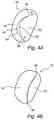
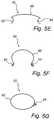
- FIGS. 5A-5Gare schematical views of different embodiments of a device according to the invention.
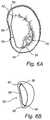
- FIGS. 6C-6Dare schematical views of a second embodiment of the device being applied to the mitral valve in a first and second shape of the device, respectively.
- FIGS. 7, 8A-8B and 9A-9Bare schematical views of a heart illustrating a method for applying a device according to the invention to the mitral valve.
- the leaflets 22 , 24are drawn apart extending into the left ventricle 14 for opening the mitral valve 18 and allowing passage of blood into the left ventricle 14 .
- the leaflets 22 , 24make contact to seal the mitral valve 18 in order to prevent blood transport from the left ventricle 14 back into the left atrium.
- the mitral valvehas an anterior leaflet 22 and a posterior leaflet 24 .
- the leaflets 22 , 24are joined at commissures 36 , 38 and the mitral valve 18 has an opening 40 between the commissures 36 , 38 .
- the anterior leaflet 22is larger than the posterior leaflet 24 , whereby the opening 40 of the mitral valve 18 has an arcuate shape.
- the opening 40is opened and closed by movement of the leaflets 22 , 24 . The movement is mainly performed by free edges 42 , 44 of the leaflets 22 , 24 between the commissures 36 , 38 .
- FIG. 3a diseased mitral valve 18 is shown.
- the leaflets 22 , 24are not able to coapt properly, whereby the opening 40 in the valve 18 is not completely closed. Blood will now leak through the opening 40 backwards from the left ventricle 14 into the left atrium. This implies that the function of the heart 12 is reduced, since blood flows backwards through the system instead of being pumped out to the aorta. Therefore, there will be a need for ensuring that the leaflets 22 , 24 are able to close the valve 18 properly.
- FIG. 4Ashows a mitral valve 18 with an opening 40 which has not been completely closed due to inability of the leaflets 22 , 24 to coapt properly.
- Arrows Aindicate a force to be applied to the valve 18 in order to remodel the valve 18 such that the leaflets 22 , 24 are to be able to close properly.
- the valveis remodeled by drawing the commissures 36 , 38 , i.e. the sites of junction between the leaflets 22 , 24 , apart. This implies that the mitral valve opening 40 is stretched and that the free edges 42 , 44 of the leaflets 22 , 24 are brought closer together.
- the leaflets 22 , 24are able to close the valve 18 preventing leakage.
- FIGS. 5A-5Gembodiments of a device 50 according to the invention for treating a diseased mitral valve 18 will be described.
- the deviceis to be inserted in the mitral valve 18 to make contact with the commissures 36 , 38 .
- the device 50will undergo a transfer of shape in order to bring the valve tissue with it and perform remodeling of the valve 18 as described above with reference to FIGS. 4A-4B .
- the device 50comprises a first contact point 52 and a second contact point 54 , which are to make contact with valve tissue at the commissures 36 , 38 , respectively.
- the device 50may be hook-shaped at the contact points 52 , 54 , whereby the device 50 may establish contact on both sides of the leaflets 22 , 24 at the commissures 36 , 38 .
- the device 50may at the contact points 52 , 54 further comprise barbs or spikes or any pointed protrusion (not shown), which may penetrate into valve tissue for fixating the device 50 to the valve tissue.
- the device 50may be arranged for being fixed by sutures or clips to the valve tissue.
- the entire device 50When implanted, the entire device 50 should make contact with the valve tissue in order to enable the device 50 growing into the valve tissue. This implies that the device 50 will not exhibit a surface of foreign material to the blood flow and thereby blood clotting is prevented.
- the device 50may have an elongate part 56 , as shown in FIGS. 5A-5F , between the contact points 52 , 54 .
- the elongate part 56may be arranged extending along valve tissue over its entire length, whereby the device 50 eventually may be fully grown into valve tissue.
- the device 50should make contact with valve tissue throughout a cycle of heart action.
- the elongate part 56is preferably placed in contact with the annulus 20 or with leaflet tissue close to the annulus 20 .
- the device 50is bent at the contact points 52 , 54 such that the elongate part may extend in a plane substantially perpendicular to a plane in which the hook-shape extend. This implies that the elongate part 56 of the device 50 may extend along valve tissue in a plane of the annulus 20 of the mitral valve 18 while the contact points 52 , 54 are arranged in contact with the commissures 36 , 38 of the mitral valve 18 .
- the elongate part 56may be fixed to contact portions of the device 50 such that the elongate part 56 may extend in the plane of the annulus 20 .
- the devicemay alternatively be ring-formed to extend mainly along the annulus 20 of the mitral valve 18 .
- the ring-formdeviates from the shape of the annulus 20 at the commissures 36 , 38 for allowing contact between the device 50 and the commissures 36 , 38 .
- the device 50is inserted to the mitral valve 18 in a first shape.
- the device 50is arranged in the first shape to establish the contact between the device 50 and the commissures 36 , 38 .
- the device 50may then transfer to a second shape for remodeling the mitral valve 18 , as shown in FIGS. 6B and 6D .
- the elongate part 56changes form between the first and second shapes of the device 50 .
- the elongate part 56becomes less arcuate or curved in order to push the contact points 52 , 54 further apart and thereby stretch the opening 40 of the mitral valve 18 such that the free edges 42 , 44 of the leaflets 22 , 24 are brought closer together.
- the device 50may be slightly flexible in its second shape to allow small movements of the annulus 20 and commissures 36 , 38 during heart action while still keeping the commissures 36 , 38 stretched apart in the remodeled shape.
- the devicemay be made of any suitable medical grade material(s), such as medical grade metals or plastics.
- the device 50may be made of a shape memory material.
- the device 50may then be inserted into the mitral valve 18 in a martensitic state, wherein the device is relatively soft and may be easily deformed.
- the device 50may in the martensitic state easily be inserted into contact with the commissures 36 , 38 of the mitral valve 18 .
- the device 50transforms into an austenitic state and assumes a programmed shape.
- the device 50has an inherent strive towards assuming the second shape and maintains its desired shape.
- the devicemay be made of a shape memory alloy, such as Nitinol, or a shape memory polymer.
- the distance between the contact points of the device in its first shapeis 18-20 mm, which corresponds to a normal distance between the commissures of the mitral valve.
- the transfer of shape of the devicemay typically create a 40% increase in the distance between the contact points for remodelling the mitral valve.
- the device 50When the device 50 has been placed in contact with the commissures 36 , 38 , the device 50 is fixed to the valve tissue. This may be accomplished by attaching portions of the device 50 to the valve tissue by means of e.g. suturing or applying one or more clips to the device and valve tissue. Alternatively, fixating means are arranged on the device 50 and penetrate into valve tissue for fixing the device 50 to the valve tissue.
- the device 50is inserted by means of a catheter 60 into the heart 12 .
- the catheter 60is entered into the body through the femoral artery 62 in the groin or the subclavian artery 64 in the arm of the patient and is guided into the heart 12 retrograde through the artery and through the aortic valve 34 into the left ventricle 14 , as shown in FIG. 8A .
- the catheter 60may be guided through vena cava into the right atrium 66 and may penetrate the interatrial septum 68 to reach the left atrium 70 , as shown in FIG. 8B .
- the device 50may be arranged in the catheter 60 on a distal end of a carrier 72 and be covered by a restraining sheath 74 , as shown in FIG. 9A .
- the carrier 72When the catheter 60 has been inserted to the mitral valve 18 , the carrier 72 may be pushed partially out of the restraining sheath 74 , as shown in FIG. 9B .
- the contact points 52 , 54 of the device 50may establish contact with the commissures 36 , 38 .
- the carrier 72may be completely pushed out of the restraining sheath 74 for allowing the device 50 to assume its second shape and remodel the mitral valve 18 .
- the device 50may be released from the carrier 72 and the catheter 60 may be withdrawn from the body leaving the device 50 in place in the mitral valve 18 .
Landscapes
- Health & Medical Sciences (AREA)
- Cardiology (AREA)
- Oral & Maxillofacial Surgery (AREA)
- Transplantation (AREA)
- Engineering & Computer Science (AREA)
- Biomedical Technology (AREA)
- Heart & Thoracic Surgery (AREA)
- Vascular Medicine (AREA)
- Life Sciences & Earth Sciences (AREA)
- Animal Behavior & Ethology (AREA)
- General Health & Medical Sciences (AREA)
- Public Health (AREA)
- Veterinary Medicine (AREA)
- Prostheses (AREA)
Abstract
Description
Claims (20)
Priority Applications (2)
| Application Number | Priority Date | Filing Date | Title |
|---|---|---|---|
| US16/246,374US10765516B2 (en) | 2004-12-15 | 2019-01-11 | Device and method for improving the function of a heart valve |
| US17/013,613US20200397580A1 (en) | 2004-12-15 | 2020-09-06 | Device and Method for Improving the Function of a Heart Valve |
Applications Claiming Priority (7)
| Application Number | Priority Date | Filing Date | Title |
|---|---|---|---|
| SE0403046ASE0403046D0 (en) | 2004-12-15 | 2004-12-15 | A device and method for improving the function of a heart valve |
| SE0403046 | 2004-12-15 | ||
| SE0403046-6 | 2004-12-15 | ||
| US63609604P | 2004-12-16 | 2004-12-16 | |
| PCT/SE2005/001914WO2006065212A1 (en) | 2004-12-15 | 2005-12-14 | A device and method for improving the function of a heart valve |
| US79302807A | 2007-06-14 | 2007-06-14 | |
| US16/246,374US10765516B2 (en) | 2004-12-15 | 2019-01-11 | Device and method for improving the function of a heart valve |
Related Parent Applications (2)
| Application Number | Title | Priority Date | Filing Date |
|---|---|---|---|
| PCT/SE2005/001914ContinuationWO2006065212A1 (en) | 2004-12-15 | 2005-12-14 | A device and method for improving the function of a heart valve |
| US11/793,028ContinuationUS10201424B2 (en) | 2004-12-15 | 2005-12-14 | Device and method for improving the function of a heart valve |
Related Child Applications (1)
| Application Number | Title | Priority Date | Filing Date |
|---|---|---|---|
| US17/013,613ContinuationUS20200397580A1 (en) | 2004-12-15 | 2020-09-06 | Device and Method for Improving the Function of a Heart Valve |
Publications (2)
| Publication Number | Publication Date |
|---|---|
| US20190183646A1 US20190183646A1 (en) | 2019-06-20 |
| US10765516B2true US10765516B2 (en) | 2020-09-08 |
Family
ID=33563209
Family Applications (3)
| Application Number | Title | Priority Date | Filing Date |
|---|---|---|---|
| US11/793,028Expired - Fee RelatedUS10201424B2 (en) | 2004-12-15 | 2005-12-14 | Device and method for improving the function of a heart valve |
| US16/246,374Expired - Fee RelatedUS10765516B2 (en) | 2004-12-15 | 2019-01-11 | Device and method for improving the function of a heart valve |
| US17/013,613AbandonedUS20200397580A1 (en) | 2004-12-15 | 2020-09-06 | Device and Method for Improving the Function of a Heart Valve |
Family Applications Before (1)
| Application Number | Title | Priority Date | Filing Date |
|---|---|---|---|
| US11/793,028Expired - Fee RelatedUS10201424B2 (en) | 2004-12-15 | 2005-12-14 | Device and method for improving the function of a heart valve |
Family Applications After (1)
| Application Number | Title | Priority Date | Filing Date |
|---|---|---|---|
| US17/013,613AbandonedUS20200397580A1 (en) | 2004-12-15 | 2020-09-06 | Device and Method for Improving the Function of a Heart Valve |
Country Status (7)
| Country | Link |
|---|---|
| US (3) | US10201424B2 (en) |
| EP (1) | EP1827315A4 (en) |
| JP (1) | JP4980239B2 (en) |
| CN (2) | CN101978933A (en) |
| CA (1) | CA2590199C (en) |
| SE (1) | SE0403046D0 (en) |
| WO (1) | WO2006065212A1 (en) |
Families Citing this family (60)
| Publication number | Priority date | Publication date | Assignee | Title |
|---|---|---|---|---|
| US6440164B1 (en) | 1999-10-21 | 2002-08-27 | Scimed Life Systems, Inc. | Implantable prosthetic valve |
| AU2003285943B2 (en) | 2002-10-24 | 2008-08-21 | Boston Scientific Limited | Venous valve apparatus and method |
| US6945957B2 (en) | 2002-12-30 | 2005-09-20 | Scimed Life Systems, Inc. | Valve treatment catheter and methods |
| US7854761B2 (en) | 2003-12-19 | 2010-12-21 | Boston Scientific Scimed, Inc. | Methods for venous valve replacement with a catheter |
| US8128681B2 (en) | 2003-12-19 | 2012-03-06 | Boston Scientific Scimed, Inc. | Venous valve apparatus, system, and method |
| US7566343B2 (en) | 2004-09-02 | 2009-07-28 | Boston Scientific Scimed, Inc. | Cardiac valve, system, and method |
| US20060173490A1 (en) | 2005-02-01 | 2006-08-03 | Boston Scientific Scimed, Inc. | Filter system and method |
| US7867274B2 (en) | 2005-02-23 | 2011-01-11 | Boston Scientific Scimed, Inc. | Valve apparatus, system and method |
| US8608797B2 (en)* | 2005-03-17 | 2013-12-17 | Valtech Cardio Ltd. | Mitral valve treatment techniques |
| US7722666B2 (en) | 2005-04-15 | 2010-05-25 | Boston Scientific Scimed, Inc. | Valve apparatus, system and method |
| US8012198B2 (en) | 2005-06-10 | 2011-09-06 | Boston Scientific Scimed, Inc. | Venous valve, system, and method |
| US8128691B2 (en) | 2005-09-07 | 2012-03-06 | Medtentia International Ltd. Oy | Device and method for improving the function of a heart valve |
| US7569071B2 (en) | 2005-09-21 | 2009-08-04 | Boston Scientific Scimed, Inc. | Venous valve, system, and method with sinus pocket |
| WO2008091493A1 (en) | 2007-01-08 | 2008-07-31 | California Institute Of Technology | In-situ formation of a valve |
| US7967853B2 (en) | 2007-02-05 | 2011-06-28 | Boston Scientific Scimed, Inc. | Percutaneous valve, system and method |
| US7892276B2 (en) | 2007-12-21 | 2011-02-22 | Boston Scientific Scimed, Inc. | Valve with delayed leaflet deployment |
| US20100121437A1 (en) | 2008-04-16 | 2010-05-13 | Cardiovascular Technologies, Llc | Transvalvular intraannular band and chordae cutting for ischemic and dilated cardiomyopathy |
| US11083579B2 (en) | 2008-04-16 | 2021-08-10 | Heart Repair Technologies, Inc. | Transvalvular intraanular band and chordae cutting for ischemic and dilated cardiomyopathy |
| US8262725B2 (en)* | 2008-04-16 | 2012-09-11 | Cardiovascular Technologies, Llc | Transvalvular intraannular band for valve repair |
| US10456259B2 (en) | 2008-04-16 | 2019-10-29 | Heart Repair Technologies, Inc. | Transvalvular intraannular band for mitral valve repair |
| US20100121435A1 (en) | 2008-04-16 | 2010-05-13 | Cardiovascular Technologies, Llc | Percutaneous transvalvular intrannular band for mitral valve repair |
| US20100131057A1 (en) | 2008-04-16 | 2010-05-27 | Cardiovascular Technologies, Llc | Transvalvular intraannular band for aortic valve repair |
| US11013599B2 (en) | 2008-04-16 | 2021-05-25 | Heart Repair Technologies, Inc. | Percutaneous transvalvular intraannular band for mitral valve repair |
| US20120179184A1 (en)* | 2009-09-15 | 2012-07-12 | Boris Orlov | Heart valve remodeling |
| WO2011047168A1 (en)* | 2009-10-14 | 2011-04-21 | Cardiovascular Technologies, Llc | Percutaneous transvalvular intraannular band for mitral valve repair |
| US8870950B2 (en) | 2009-12-08 | 2014-10-28 | Mitral Tech Ltd. | Rotation-based anchoring of an implant |
| US8657872B2 (en) | 2010-07-19 | 2014-02-25 | Jacques Seguin | Cardiac valve repair system and methods of use |
| US11653910B2 (en) | 2010-07-21 | 2023-05-23 | Cardiovalve Ltd. | Helical anchor implantation |
| DK4233795T3 (en)* | 2010-10-05 | 2024-08-26 | Edwards Lifesciences Corp | Prosthetic heart valve |
| US8845717B2 (en) | 2011-01-28 | 2014-09-30 | Middle Park Medical, Inc. | Coaptation enhancement implant, system, and method |
| US8888843B2 (en) | 2011-01-28 | 2014-11-18 | Middle Peak Medical, Inc. | Device, system, and method for transcatheter treatment of valve regurgitation |
| US9668859B2 (en) | 2011-08-05 | 2017-06-06 | California Institute Of Technology | Percutaneous heart valve delivery systems |
| US20150351906A1 (en) | 2013-01-24 | 2015-12-10 | Mitraltech Ltd. | Ventricularly-anchored prosthetic valves |
| CA2898984C (en)* | 2013-01-25 | 2021-03-16 | Medtentia International Ltd Oy | A medical device and method for facilitating selection of an annuloplasty implant |
| EP2948100B1 (en)* | 2013-01-25 | 2021-05-05 | Medtentia International Ltd Oy | A system for cardiac valve repair |
| WO2014144247A1 (en) | 2013-03-15 | 2014-09-18 | Arash Kheradvar | Handle mechanism and functionality for repositioning and retrieval of transcatheter heart valves |
| US10166098B2 (en) | 2013-10-25 | 2019-01-01 | Middle Peak Medical, Inc. | Systems and methods for transcatheter treatment of valve regurgitation |
| EP3157469B2 (en) | 2014-06-18 | 2024-10-02 | Polares Medical Inc. | Mitral valve implants for the treatment of valvular regurgitation |
| CA2958065C (en) | 2014-06-24 | 2023-10-31 | Middle Peak Medical, Inc. | Systems and methods for anchoring an implant |
| EP3174502B1 (en) | 2014-07-30 | 2022-04-06 | Cardiovalve Ltd | Apparatus for implantation of an articulatable prosthetic valve |
| CN110141399B (en) | 2015-02-05 | 2021-07-27 | 卡迪尔维尔福股份有限公司 | Prosthetic valve with axial sliding frame |
| CN108348334A (en)* | 2015-10-27 | 2018-07-31 | 谢尔蒂斯有限公司 | Medical devices using bioabsorbable materials |
| US9592121B1 (en) | 2015-11-06 | 2017-03-14 | Middle Peak Medical, Inc. | Device, system, and method for transcatheter treatment of valvular regurgitation |
| US10531866B2 (en) | 2016-02-16 | 2020-01-14 | Cardiovalve Ltd. | Techniques for providing a replacement valve and transseptal communication |
| US20190231525A1 (en) | 2016-08-01 | 2019-08-01 | Mitraltech Ltd. | Minimally-invasive delivery systems |
| CA3031187A1 (en) | 2016-08-10 | 2018-02-15 | Cardiovalve Ltd. | Prosthetic valve with concentric frames |
| AU2017382273A1 (en) | 2016-12-22 | 2019-08-08 | Heart Repair Technologies, Inc. | Percutaneous delivery systems for anchoring an implant in a cardiac valve annulus |
| US10653524B2 (en) | 2017-03-13 | 2020-05-19 | Polares Medical Inc. | Device, system, and method for transcatheter treatment of valvular regurgitation |
| US10478303B2 (en) | 2017-03-13 | 2019-11-19 | Polares Medical Inc. | Device, system, and method for transcatheter treatment of valvular regurgitation |
| JP7159230B2 (en) | 2017-03-13 | 2022-10-24 | ポラレス・メディカル・インコーポレイテッド | Devices, systems and methods for transcatheter treatment of valvular regurgitation |
| US12064347B2 (en) | 2017-08-03 | 2024-08-20 | Cardiovalve Ltd. | Prosthetic heart valve |
| US11793633B2 (en) | 2017-08-03 | 2023-10-24 | Cardiovalve Ltd. | Prosthetic heart valve |
| WO2019097510A1 (en)* | 2017-11-15 | 2019-05-23 | Tel Hashomer Medical Research, Infrastructure And Services Ltd. | Mitral brace |
| WO2019226803A1 (en) | 2018-05-22 | 2019-11-28 | Boston Scientific Scimed, Inc. | Percutaneous papillary muscle relocation |
| WO2020167672A1 (en) | 2019-02-11 | 2020-08-20 | Subramanian Valavanur A | Percutaneous delivery systems for anchoring an implant in a cardiac valve annulus |
| EP3962417A4 (en) | 2019-05-02 | 2023-01-18 | University of Maryland, Baltimore | VALVE TRANSLOCATION DEVICE AND METHODS FOR TREATMENT OF FUNCTIONAL VALVE REGURGITATION |
| WO2021005246A1 (en)* | 2019-07-11 | 2021-01-14 | Medtentia International Ltd Oy | Annuloplasty device |
| US12357459B2 (en) | 2020-12-03 | 2025-07-15 | Cardiovalve Ltd. | Transluminal delivery system |
| US11464634B2 (en) | 2020-12-16 | 2022-10-11 | Polares Medical Inc. | Device, system, and method for transcatheter treatment of valvular regurgitation with secondary anchors |
| US11759321B2 (en) | 2021-06-25 | 2023-09-19 | Polares Medical Inc. | Device, system, and method for transcatheter treatment of valvular regurgitation |
Citations (9)
| Publication number | Priority date | Publication date | Assignee | Title |
|---|---|---|---|---|
| WO1999004730A1 (en) | 1997-07-22 | 1999-02-04 | Baxter International Inc. | Expandable annuloplasty ring |
| US6217610B1 (en) | 1994-07-29 | 2001-04-17 | Edwards Lifesciences Corporation | Expandable annuloplasty ring |
| US6602289B1 (en) | 1999-06-08 | 2003-08-05 | S&A Rings, Llc | Annuloplasty rings of particular use in surgery for the mitral valve |
| US6723038B1 (en) | 2000-10-06 | 2004-04-20 | Myocor, Inc. | Methods and devices for improving mitral valve function |
| US20040127982A1 (en) | 2002-10-01 | 2004-07-01 | Ample Medical, Inc. | Devices, systems, and methods for reshaping a heart valve annulus |
| US20040127981A1 (en) | 2000-09-20 | 2004-07-01 | Ample Medical, Inc. | Devices, systems, and methods for retaining a native heart valve leaflet |
| US20040220593A1 (en) | 2003-05-01 | 2004-11-04 | Secant Medical, Llc | Restraining clip for mitral valve repair |
| US20040236419A1 (en) | 2001-12-21 | 2004-11-25 | Simcha Milo | Implantation system for annuloplasty rings |
| US20040260393A1 (en) | 2000-09-20 | 2004-12-23 | Ample Medical, Inc. | Devices, systems, and methods for reshaping a heart valve annulus |
Family Cites Families (7)
| Publication number | Priority date | Publication date | Assignee | Title |
|---|---|---|---|---|
| JPH05184611A (en)* | 1991-03-19 | 1993-07-27 | Kenji Kusuhara | Valvular annulation retaining member and its attaching method |
| US6250308B1 (en)* | 1998-06-16 | 2001-06-26 | Cardiac Concepts, Inc. | Mitral valve annuloplasty ring and method of implanting |
| SE514718C2 (en)* | 1999-06-29 | 2001-04-09 | Jan Otto Solem | Apparatus for treating defective closure of the mitral valve apparatus |
| MXPA02011590A (en)* | 2000-05-25 | 2004-07-30 | Bioring S A | Device for shrinking or reinforcing the heart valvular orifices. |
| US6419696B1 (en)* | 2000-07-06 | 2002-07-16 | Paul A. Spence | Annuloplasty devices and related heart valve repair methods |
| AU2002362442B2 (en)* | 2001-10-01 | 2008-08-07 | Ample Medical, Inc. | Methods and devices for heart valve treatments |
| US6797001B2 (en)* | 2002-03-11 | 2004-09-28 | Cardiac Dimensions, Inc. | Device, assembly and method for mitral valve repair |
- 2004
- 2004-12-15SESE0403046Apatent/SE0403046D0/enunknown
- 2005
- 2005-12-14CACA2590199Apatent/CA2590199C/ennot_activeExpired - Fee Related
- 2005-12-14EPEP05819067.9Apatent/EP1827315A4/ennot_activeCeased
- 2005-12-14WOPCT/SE2005/001914patent/WO2006065212A1/enactiveApplication Filing
- 2005-12-14JPJP2007546607Apatent/JP4980239B2/ennot_activeExpired - Fee Related
- 2005-12-14USUS11/793,028patent/US10201424B2/ennot_activeExpired - Fee Related
- 2005-12-14CNCN201010138346XApatent/CN101978933A/enactivePending
- 2005-12-14CNCN2005800429675Apatent/CN101087571B/ennot_activeExpired - Fee Related
- 2019
- 2019-01-11USUS16/246,374patent/US10765516B2/ennot_activeExpired - Fee Related
- 2020
- 2020-09-06USUS17/013,613patent/US20200397580A1/ennot_activeAbandoned
Patent Citations (10)
| Publication number | Priority date | Publication date | Assignee | Title |
|---|---|---|---|---|
| US6217610B1 (en) | 1994-07-29 | 2001-04-17 | Edwards Lifesciences Corporation | Expandable annuloplasty ring |
| US20010021874A1 (en) | 1994-07-29 | 2001-09-13 | Alexandre Carpentier | Expandable annuloplasty ring |
| WO1999004730A1 (en) | 1997-07-22 | 1999-02-04 | Baxter International Inc. | Expandable annuloplasty ring |
| US6602289B1 (en) | 1999-06-08 | 2003-08-05 | S&A Rings, Llc | Annuloplasty rings of particular use in surgery for the mitral valve |
| US20040127981A1 (en) | 2000-09-20 | 2004-07-01 | Ample Medical, Inc. | Devices, systems, and methods for retaining a native heart valve leaflet |
| US20040260393A1 (en) | 2000-09-20 | 2004-12-23 | Ample Medical, Inc. | Devices, systems, and methods for reshaping a heart valve annulus |
| US6723038B1 (en) | 2000-10-06 | 2004-04-20 | Myocor, Inc. | Methods and devices for improving mitral valve function |
| US20040236419A1 (en) | 2001-12-21 | 2004-11-25 | Simcha Milo | Implantation system for annuloplasty rings |
| US20040127982A1 (en) | 2002-10-01 | 2004-07-01 | Ample Medical, Inc. | Devices, systems, and methods for reshaping a heart valve annulus |
| US20040220593A1 (en) | 2003-05-01 | 2004-11-04 | Secant Medical, Llc | Restraining clip for mitral valve repair |
Non-Patent Citations (1)
| Title |
|---|
| WIPO, Swedish International Preliminary Examining Authority, International Preliminary Report on Patentability dated Jun. 19, 2007 in International Patent Application No. PCT/SE2005/001914, 7 pages. |
Also Published As
| Publication number | Publication date |
|---|---|
| CN101087571B (en) | 2010-05-12 |
| EP1827315A4 (en) | 2017-05-31 |
| CA2590199A1 (en) | 2006-06-22 |
| JP4980239B2 (en) | 2012-07-18 |
| US20080109075A1 (en) | 2008-05-08 |
| US20200397580A1 (en) | 2020-12-24 |
| EP1827315A1 (en) | 2007-09-05 |
| SE0403046D0 (en) | 2004-12-15 |
| JP2008523886A (en) | 2008-07-10 |
| US20190183646A1 (en) | 2019-06-20 |
| CN101978933A (en) | 2011-02-23 |
| CN101087571A (en) | 2007-12-12 |
| CA2590199C (en) | 2014-01-21 |
| WO2006065212A1 (en) | 2006-06-22 |
| US10201424B2 (en) | 2019-02-12 |
Similar Documents
| Publication | Publication Date | Title |
|---|---|---|
| US10765516B2 (en) | Device and method for improving the function of a heart valve | |
| US20220117733A1 (en) | Device And Method For Improving The Function Of A Heart Valve | |
| US9526614B2 (en) | System for improving the function of a heart valve | |
| EP2293739B1 (en) | Heart valve repair device | |
| US6869444B2 (en) | Low invasive implantable cardiac prosthesis and method for helping improve operation of a heart valve | |
| EP1418865B1 (en) | Self-moulding annuloplasty ring | |
| CN102014796A (en) | A stent that positions and anchors a valve prosthesis at its implantation site in the patient's heart |
Legal Events
| Date | Code | Title | Description |
|---|---|---|---|
| FEPP | Fee payment procedure | Free format text:ENTITY STATUS SET TO UNDISCOUNTED (ORIGINAL EVENT CODE: BIG.); ENTITY STATUS OF PATENT OWNER: SMALL ENTITY | |
| FEPP | Fee payment procedure | Free format text:ENTITY STATUS SET TO SMALL (ORIGINAL EVENT CODE: SMAL); ENTITY STATUS OF PATENT OWNER: SMALL ENTITY | |
| STPP | Information on status: patent application and granting procedure in general | Free format text:DOCKETED NEW CASE - READY FOR EXAMINATION | |
| STPP | Information on status: patent application and granting procedure in general | Free format text:NON FINAL ACTION MAILED | |
| STPP | Information on status: patent application and granting procedure in general | Free format text:RESPONSE TO NON-FINAL OFFICE ACTION ENTERED AND FORWARDED TO EXAMINER | |
| ZAAA | Notice of allowance and fees due | Free format text:ORIGINAL CODE: NOA | |
| ZAAB | Notice of allowance mailed | Free format text:ORIGINAL CODE: MN/=. | |
| STPP | Information on status: patent application and granting procedure in general | Free format text:NOTICE OF ALLOWANCE MAILED -- APPLICATION RECEIVED IN OFFICE OF PUBLICATIONS | |
| ZAAA | Notice of allowance and fees due | Free format text:ORIGINAL CODE: NOA | |
| STCF | Information on status: patent grant | Free format text:PATENTED CASE | |
| AS | Assignment | Owner name:MEDTENTIA INTERNATIONAL LTD OY, SWEDEN Free format text:ASSIGNMENT OF ASSIGNORS INTEREST;ASSIGNOR:KERAENEN, OLLI;REEL/FRAME:062954/0359 Effective date:20101026 | |
| FEPP | Fee payment procedure | Free format text:MAINTENANCE FEE REMINDER MAILED (ORIGINAL EVENT CODE: REM.); ENTITY STATUS OF PATENT OWNER: SMALL ENTITY | |
| LAPS | Lapse for failure to pay maintenance fees | Free format text:PATENT EXPIRED FOR FAILURE TO PAY MAINTENANCE FEES (ORIGINAL EVENT CODE: EXP.); ENTITY STATUS OF PATENT OWNER: SMALL ENTITY | |
| STCH | Information on status: patent discontinuation | Free format text:PATENT EXPIRED DUE TO NONPAYMENT OF MAINTENANCE FEES UNDER 37 CFR 1.362 | |
| FP | Lapsed due to failure to pay maintenance fee | Effective date:20240908 |